Panasonic of North America TUWHT1U 2.4 GHz and 60 GHz Wireless HD Unit User Manual tc p54z1 eng 2488 indb
Panasonic Corporation of North America 2.4 GHz and 60 GHz Wireless HD Unit tc p54z1 eng 2488 indb
User Manual
HD3D Sound
ViV
A
TM
Quick Start Guide
(See page 8-24)
Operating Instructions
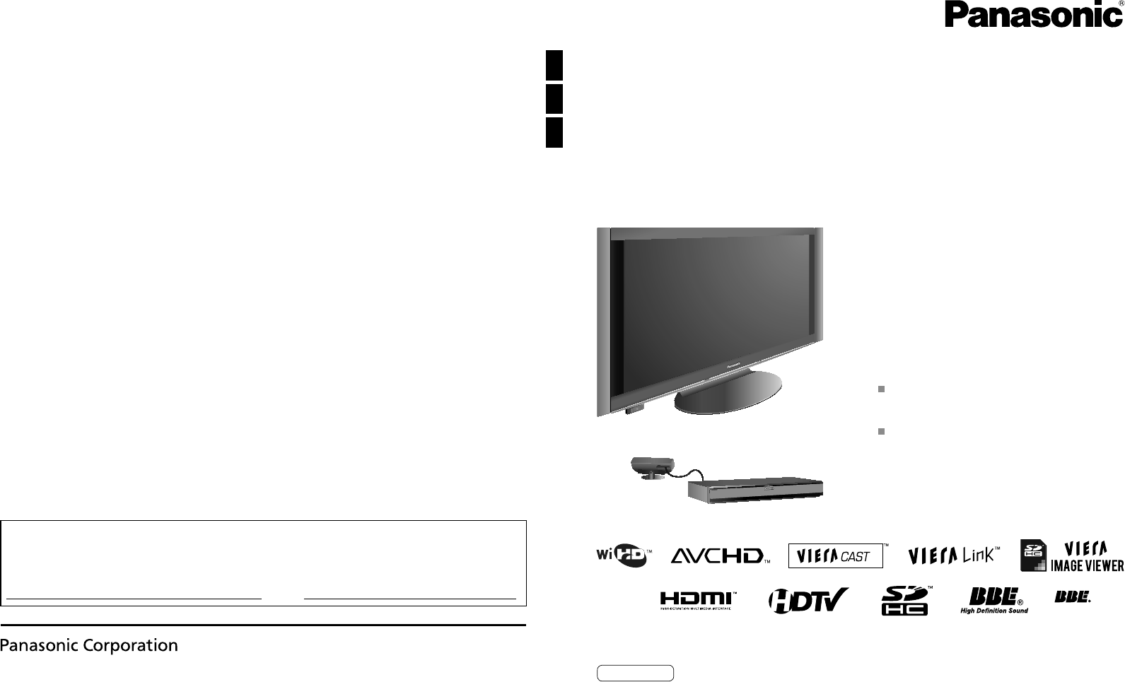
54” Class 1080p Plasma HDTV
(54.1 inches measured diagonally)
Model No. TC-P54Z1
Customer’s Record
The model number and serial number of this product can be found on its back cover. You should note this serial number in
the space provided below and retain this book, plus your purchase receipt, as a permanent record of your purchase to aid
in identification in the event of theft or loss, and for Warranty Service purposes.
Model Number Serial Number
Web Site: http://panasonic.net/
Panasonic Corporation 2009 Printed in Japan
PBS0109F0
For assistance (U.S.A./Puerto Rico), please call:
1-877-95-VIERA (958-4372)
or visit us at www.panasonic.com/contactinfo
For assistance (Canada), please call:
1-866-330-0014
or visit us at www.vieraconcierge.ca
TQBC2488
English
Please read these instructions before operating your set and retain them for future reference.
The images shown in this manual are for illustrative purposes only.
2 3
Viewing Advanced FAQs, etc.
Quick Start
Guide
VIERA Link™ is a trademark of Panasonic
Corporation. VIERA CAST™ is a trademark of
Panasonic Corporation. SDHC Logo is a trademark.
H
D3D Sou
nd
ViV
A
Manufactured under
license from BBE Sound,
Inc.
Licensed by BBE Sound, Inc. under
one or more of the following US
patents: 5510752, 5736897.
BBE and BBE symbol are registered
trademarks of BBE Sound, Inc.
HDMI, the HDMI logo and High-Definition
Multimedia Interface are trademarks or
registered trademarks of HDMI Licensing
LLC.
Manufactured under license from
Dolby Laboratories.
Dolby and the double-D symbol are
trademarks of Dolby Laboratories.
HDAVI Control™ is a trademark of Panasonic Corporation.
The WiHD™ logo is licensed for use by WirelessHD, LLC.
Watching TV ···············································25
Using VIERA TOOLS ·································27
Viewing from an SD Card ··························28
Watching Videos and DVDs ·······················32
VIERA CASTTM ···········································34
Network Camera ········································36
Displaying PC Screen on TV ·····················38
How to Use Menu Functions
(picture, sound quality, etc.) ·······················40
VIERA LinkTM “HDAVI ControlTM” ················44
Network setting ··········································50
VIERA CAST setting ··································52
Lock ···························································54
Editing and Setting Channels·····················56
Closed Caption ··········································58
Input Labels ···············································59
Using Timer ················································60
Remote pairing ···········································61
Recommended AV Connections ················62
Ratings List for Lock ··································63
Technical Information ·································64
Care and Cleaning ·····································68
Specifications ·············································69
FAQ ····························································70
Limited Warranty
(for U.S.A. and Puerto Rico only)···············72
Customer Services Directory
(for U.S.A. and Puerto Rico) ······················73
Limited Warranty (for Canada) ···················74
Enjoy your TV!
Basic Features
Advanced Features
FAQs, etc.
Safety Precautions ·······································4
Notes ····························································7
Please read before using the unit
Turn your own living room into a movie theater!
Experience an amazing level of multimedia excitement
Accessories/Optional Accessory ····· 8
Basic Connection ··························· 15
Identifying Controls ························ 19
First Time Setup····························· 21
Quick Start Guide
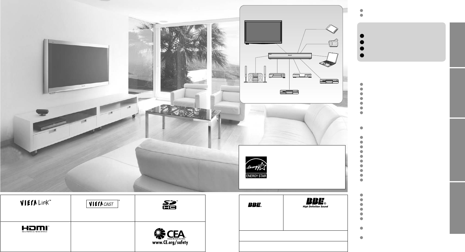
Enjoy rich multimedia
SD memory card
Camcorder
Amplifier
Home theater
system
VCR
DVD recorder/
Blu-ray Disc recorder
Set Top Box
DVD player/
Blu-ray Disc player
Contents
Personal
computer
This product qualifies for ENERGY
STAR in the “Home” setting and this is
the setting in which energy savings will
be achieved. Any modifications to the
“Home” setting or other factory default
settings could result in greater energy
consumption beyond levels that meet
ENERGY STAR qualifications.
4 5
Safety Precautions
WARNING: To reduce the risk of fire or electric shock, do not expose this apparatus to rain or moisture.
Do not place liquid containers (flower vase, cups, cosmetics, etc.) above the set
(including on shelves above, etc.).
Important Safety Instructions
1) Read these instructions.
2) Keep these instructions.
3) Heed all warnings.
4) Follow all instructions.
5) Do not use this apparatus near water.
6) Clean only with dry cloth.
7) Do not block any ventilation openings. Install in
accordance with the manufacturer’s instructions.
8) Do not install near any heat sources such as radiators,
heat registers, stoves, or other apparatus (including
amplifiers) that produce heat.
9) Do not defeat the safety purpose of the polarized or
grounding-type plug. A polarized plug has two blades with
one wider than the other. A grounding type plug has two
blades and a third grounding prong. The wide blade or the
third prong are provided for your safety. If the provided
plug does not fit into your outlet, consult an electrician for
replacement of the obsolete outlet.
10) Protect the power cord from being walked on or pinched
particularly at plugs, convenience receptacles, and the
point where they exit from the apparatus.
11) Only use attachments / accessories specified by the
manufacturer.
12) Use only with the cart, stand, tripod,
bracket, or table specified by the
manufacturer, or sold with the
apparatus. When a cart is used,
use caution when moving the cart /
apparatus combination to avoid injury
from tip-over.
13) Unplug this apparatus during lightning storms or when
unused for long periods of time.
14) Refer all servicing to qualified service personnel. Servicing
is required when the apparatus has been damaged in any
way, such as power-supply cord or plug is damaged, liquid
has been spilled or objects have fallen into the apparatus,
the apparatus has been exposed to rain or moisture, does
not operate normally, or has been dropped.
15) To prevent electric shock, ensure the grounding pin on the
AC cord power plug is securely connected.
CAUTION
RISK OF ELECTRIC SHOCK
DO NOT OPEN
WARNING: To reduce the risk of electric shock, do not remove cover or back.
No user-serviceable parts inside. Refer servicing to qualified service personnel.
The lightning flash with
arrowhead within a triangle is
intended to tell the user that
parts inside the product are a
risk of electric shock to persons.
The exclamation point within
a triangle is intended to
tell the user that important
operating and servicing
instructions are in the papers
with the appliance.
WARNING/CAUTION
WARNING
Small parts can present choking hazard if accidentally
swallowed.
Keep small parts away from young children.
Discard unneeded small parts and other objects, including
packaging materials and plastic bags/sheets to prevent
them from being played with by young children, creating
the potential risk of suffocation.
Set up
This Plasma TV may fall and can cause personal injury or
even death if not installed correctly. To prevent personal injury
or death, follow these warnings:
Install the Plasma TV in accordance with the
manufacturer’s recommended pedestal or stand,
corresponding hardware and installation instructions.
This Plasma TV is for use only with the following optional
accessories. Use with any other type of optional accessories
may cause instability. The following accessories are
manufactured by Panasonic Corporation.
• Wall-hanging bracket (Vertical) TY-WK5P1SW
Be sure to ask a qualified technician to carry out the
installation and set-up.
Two or more people are required to install or remove the
television.
Some wall mounts (wall-hanging brackets) are not
designed to be mounted to walls with steel studs or old
cinder block constructions.
Ask your dealer or licensed contractor to properly secure the
wall-hanging bracket.
Do not place the Plasma TV or its stand on a sloped or
unstable surface.
The Plasma TV may fall or tip over.
Do not support the Plasma TV on a non-specified
pedestal.
Do not place the Plasma TV on furniture that can easily
be used as steps, such as a chest of drawers.
Do not climb or allow children to climb on the Plasma TV
Place or install the Plasma TV where it cannot be pushed,
pulled over or knocked down.
Route all cords and cables such that they cannot be
tripped over or pulled by curious children.
Do not place any objects on top of the Plasma TV.
If water spills onto the Plasma TV or foreign objects get
inside it, a short-circuit may occur which could result in fire
or electric shock. If any foreign objects get inside the Plasma
TV, please consult an Authorized Service Center.
AC Power Supply Cord
To prevent fire or electric shock:
The Plasma TV is designed to operate on a 120 V AC,
60 Hz service. Insert the power cord plug as far as it will
go into the wall socket.
If the plug is not fully inserted, heat may generate, which
could cause a fire.
Do not handle the power cord plug with wet hands.
Do not do anything that might damage the power supply
cord.
When disconnecting the power supply cord, hold the
plug, not the cord.
Handling the power supply cord
Insert the power plug fully into the socket outlet. (If the
power plug is loose, it could generate heat and cause fire.)
Ensure that the power plug is easily accessible.
Ensure the earth pin on the power plug is securely
connected to prevent electrical shock.
•
An apparatus with CLASS I construction shall be connected to
a power socket outlet with a protective earthing connection.
Do not touch the power plug with a wet hand. (This may
cause electrical shock.)
Do not use any power cord other than that provided with
this TV. (This may cause fire or electrical shock.)
Do not damage the power cord. (A damaged cord may
cause fire or electrical shock.)
•
Do not move the TV with the cord plugged in the socket outlet.
• Do not place a heavy object on the cord or place the cord
near a high-temperature object.
• Do not twist the cord, bend it excessively, or stretch it.
• Do not pull on the cord. Hold onto the power plug body
when disconnecting cord.
• Do not use a damaged power plug or socket outlet.
Radio waves
Do not place this TV in any medical institutions or
locations with medical devices.
Radio waves from this TV may interfere with the medical
devices and cause accidents due to the malfunction.
Do not use this TV near any automatic control devices
such as automatic doors or fire alarms.
Radio waves from this TV may interfere with the automatic
control devices and cause accidents due to the malfunction.
Keep the RF remote control, Tuner Box and Wireless Unit
away at least 8.7 inches (22 cm) from the location where
a cardiac pacemaker is implanted.
Radio waves from this TV may interfere with the operation of
the pacemaker.
Do not disassemble the RF remote control, Tuner Box or
Wireless Unit.
It may cause troubles such as difficulties in communication.
If Problems Occur During Use
If a problem occurs (such as no picture or no sound),
or if smoke or an abnormal odor is detected from the
Plasma TV, unplug the power supply cord immediately.
Continued use of the TV under these conditions might cause
a fire or permanent damage to the TV. Have the TV evaluated
by an Authorized Service Center. Servicing of the TV by
unauthorized personnel is strongly discouraged due to its
high voltage.
If water or an object gets inside the Plasma TV, if the
Plasma TV is dropped, or if the enclosure becomes
damaged, unplug the power supply cord immediately.
A short-circuit may occur, which could cause a fire. Contact
an Authorized Service Center for an evaluation.
CAUTION
Do not cover the ventilation holes.
Doing so may cause the Plasma TV to overheat, which can
cause a fire or damage to the Plasma TV.
Leave a space of 3 15/16” (10 cm) or more at the top, left
and right, and 2 3/4” (7 cm) or more at the rear.
When using the pedestal, keep the space between the
bottom of the TV and the pedestal or stand surface clear
from objects that may obstruct ventilation.
When Moving the Plasma TV
Be sure to disconnect all cables before moving the
Plasma TV.
Moving the TV with its cables attached might damage the
cables which, in turn, can cause fire or electric shock
To prevent an electric shock, disconnect the power
plug from the wall outlet as a safety precaution before
carrying out any cleaning.
Transport only in upright position
Transporting the unit with its display panel facing upright or
downward may cause damage to the internal circuitry.
Using a dry cloth, clean any dust from the power supply
cord and plug regularly.
Build-up of dust on the power cord plug can increase
humidity, which might damage the insulation and cause a fire.
This Plasma TV radiates infrared rays;
therefore, it may affect other infrared communication
equipment. Install your infrared sensor in a place away from
direct or reflected light from your Plasma TV.
The TV will still consume some power as long as the power
supply cord is connected to the wall outlet.
Display panel is made of glass. Do not apply strong force
or impact to the display panel.
This may cause damage resulting in injury.
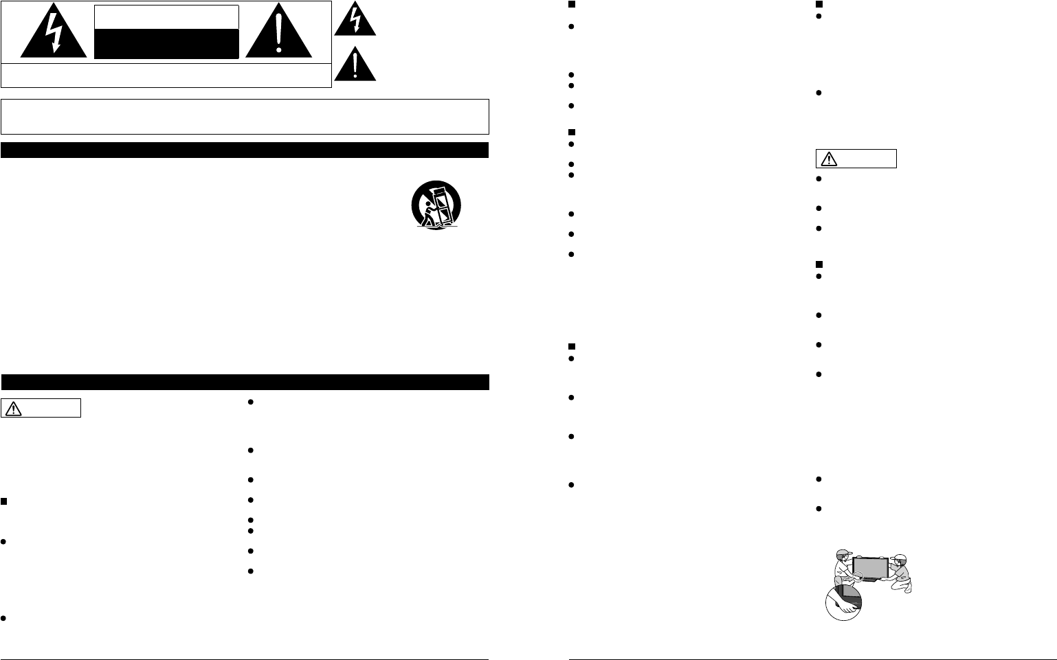
The TV is heavy. TV should be handled by 2 or more
people. Support as shown to avoid injury by the TV
tipping or falling.
When the Wireless Unit (Receiver) is attached, do not hold it.
6 7
CEA CHILD SAFETY NOTICES: Flat panel displays are not always supported on the proper stands or
installed according to the manufacturer’s recommendations. Flat panel displays that are inappropriately
situated on dressers, bookcases, shelves, desks, speakers, chests or carts may fall over and may cause
personal injury or even death.
The consumer electronics industry (of which Panasonic is a member) is committed to making home
entertainment enjoyable and safe. To prevent personal injury or death, be sure to follow the following safety
guidelines:
TUNE INTO SAFETY:
•One size does NOT fit all. Follow the manufacturer’s recommendations for the safe installation and use
of your flat panel display.
•Carefully read and understand all enclosed instructions for proper use of this product.
•Don’t allow children to climb on or play with furniture and television sets.
•Don’t place flat panel displays on furniture that can easily be used as steps, such as a chest of drawers.
•Remember that children can become excited while watching a program, especially on “larger than life”
flat panel displays. Care should be taken to install the display where it cannot be pushed, pulled over,
or knocked down.
•Care should be taken to route all cords and cables connected to the flat panel display so that they
cannot be pulled or grabbed by curious children.
WALL MOUNTING: IF YOU DECIDE TO WALL MOUNT YOUR FLAT PANEL DISPLAY, ALWAYS:
•Use a mount that has been recommended by the display manufacturer and/or listed by an independent
laboratory (such as UL, CSA, ETL).
•Follow all instructions supplied by the display and wall mount manufacturers.
•If you have any doubts about your ability to safely install your flat panel display, contact your retailer
about professional installation.
•Make sure the wall where you are mounting the display is appropriate. Some wall mounts are not
designed to be mounted to walls with steel studs or old cinder block construction. If you are unsure,
contact a professional installer.
•A minimum of two people are required for installation. Flat panel displays can be heavy.
Panasonic recommends that a qualified installer perform the wall-mount
installation. See page 4.
Safety Precautions (Continued)
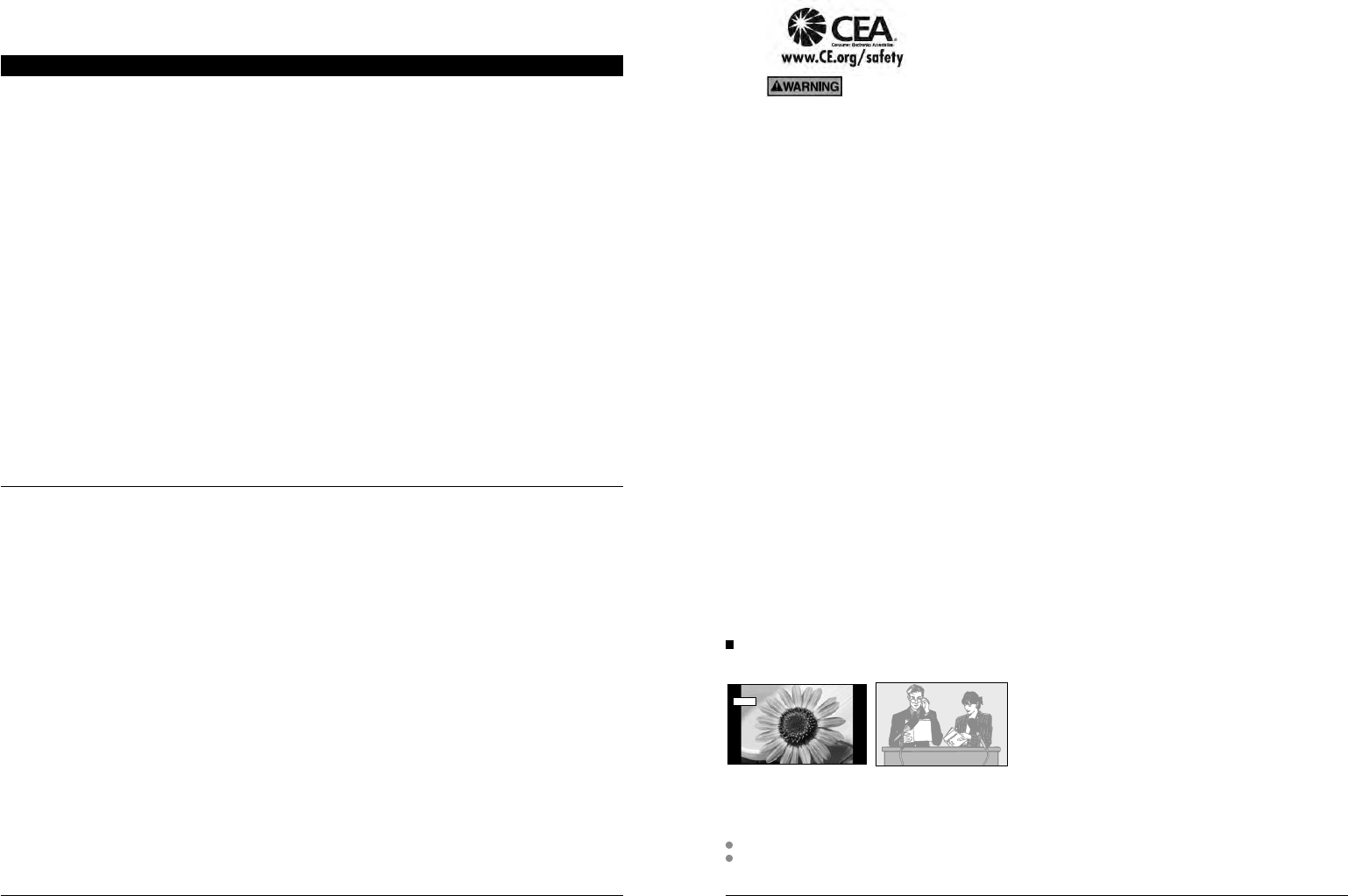
Do not display a still picture for a long time
This causes the image to remain on the plasma screen
(“Image retention”). This is not considered a malfunction and is not covered by the warranty.
4 : 3
12 To prevent “Image retention”, the screen saver is
automatically activated after a few minutes if no signals are
sent or no operations are performed. (p. 71)
Typical still images
• Channel number and other logos
• Image displayed in 4:3 mode
• SD Card photo • Video game • Computer image
Set up
Do not place the unit where it’s exposed to sunlight or other bright light (including reflections).
Use of some types of fluorescent lighting may reduce the remote control’s transmission range.
Notes
FCC STATEMENT
FCC RF Exposure Warning:
• This product contains wireless transmitter that complies with FCC radiation exposure limits set forth for an uncontrolled
environment.
• This product’s internal mounted wireless transmitter must not be installed or operated within 20 cm (8 inches) spacing between
all person’s body (excluding extremities of hands, wrist and feet for RF remote control) and other outside wireless transmitters.
• This product’s wireless transmitter must not be co-located or operated with any other antenna or transmitter.
This equipment has been tested and found to comply with the limits for a Class B digital device, pursuant to Part 15 of the FCC
Rules. These limits are designed to provide reasonable protection against harmful interference in a residential installation.
This equipment generates, uses and can radiate radio frequency energy and, if not installed and used in accordance with the
instructions, may cause harmful interference to radio communications. However, there is no guarantee that interference will not occur in
a particular installation. If this equipment does cause harmful interference to radio or television reception, which can be determined by
turning the equipment off and on, the user is encouraged to try to correct the interference by one or more of the following measures:
• Reorient or relocate the receiving antenna.
• Increase the separation between the equipment and receiver.
• Connect the equipment into an outlet on a circuit different from that to which the receiver is connected.
• Consult the dealer or an experienced radio/TV technician for help.
This device complies with Part 15 of the FCC Rules and RSS-210 of Industry Canada. Operation is subject to the following two conditions:
(1) This device may not cause harmful interference, and (2) this device must accept any interference received, including interference that
may cause undesired operation.
FCC Caution:
To assure continued compliance, follow the attached installation instructions and use only shielded interface cables
when connecting to computer or peripheral devices. Any changes or modifications not expressly approved by Panasonic
Corp. of North America could void the user’s authority to operate this device.
FCC Declaration of Conformity
Model No. TC-P54Z1
Responsible Party: Panasonic Corporation of North America
One Panasonic Way, Secaucus, NJ 07094
Contact Source: Panasonic Consumer Electronics Company
1-877-95-VIERA (958-4372)
email: consumerproducts@panasonic.com
CANADIAN NOTICE:
For Model TC-P54Z1
This Class B digital apparatus complies with Canadian ICES-003.
8 9
Quick Start
Guide Accessories/Optional Accessory
Accessories
Assembly screws
A
M8 × 30 (Silver) (2)
B
M4 × 10 (Black) (4)
C
M5 × 25 (Black) (4)
Base (1)
Frame (1)
Holder cover (1)
V
I
E
R
A
C
A
S
T
V
I
E
R
A
T
O
O
L
S
V
I
E
R
A
L
i
n
k
Accessories/Optional Accessory
Accessories
Check you have all the items shown.
Remote Control
Transmitter
N2QAYB000005
Batteries for the Remote
Control Transmitter (2)
AA Battery
Pedestal
TBLX0107
Product Registration Card
(U.S.A.)
Customer Care Plan Card
(U.S.A.)
Operating Instructions
Quick Setup Guide
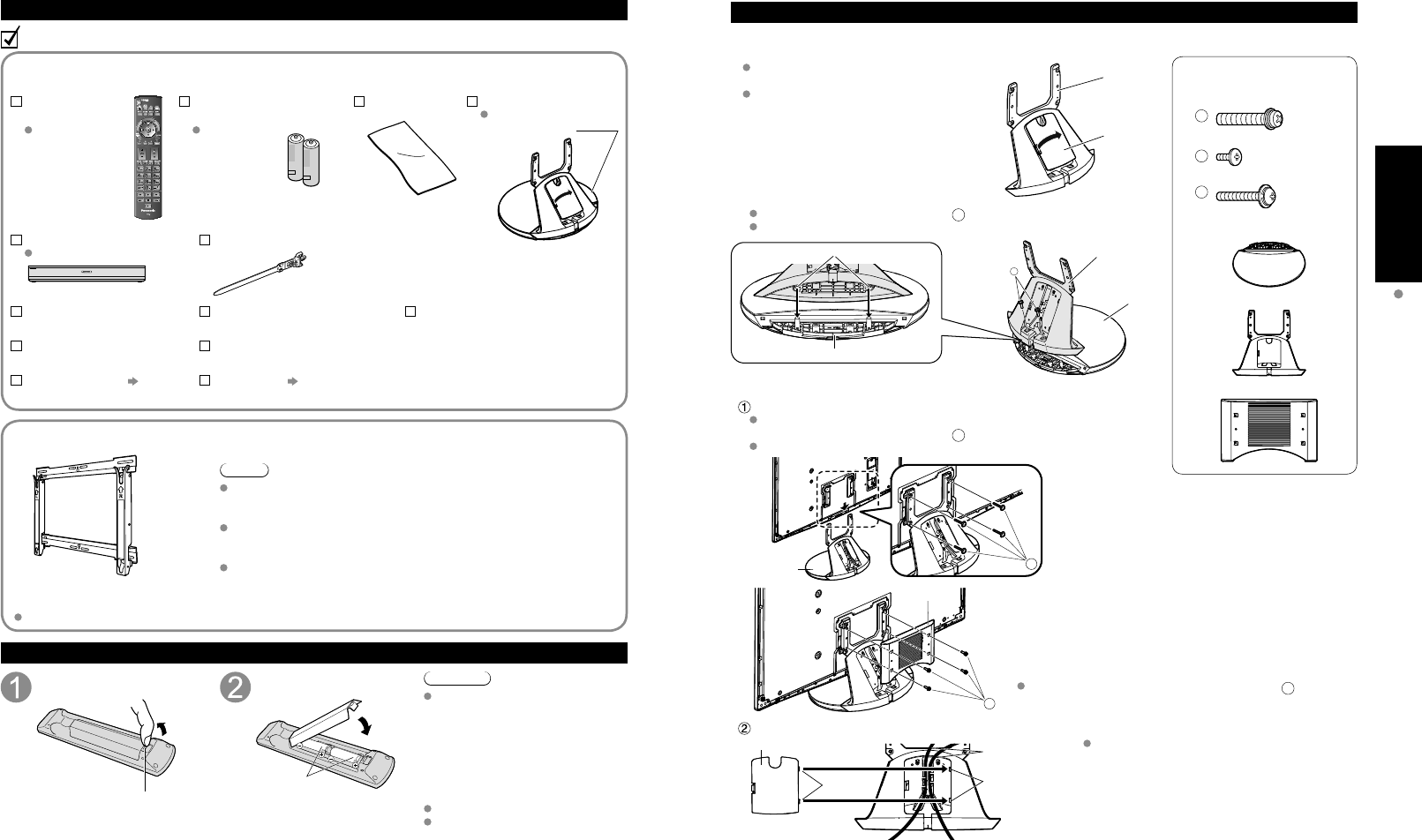
Installing the remote’s batteries
Pull open
Hook Note the correct
polarity (+ or -).
Close
Caution
Incorrect installation may cause battery
leakage and corrosion, resulting in
damage to the remote control.
•
Do not mix old and new batteries.
•
Do not mix different battery types
(such as alkaline and manganese
batteries).
•
Do not use rechargeable (Ni-Cd)
batteries.
Do not burn or break batteries.
Do not disassemble or modify the
remote control.
Optional Accessory
Note
In order to maintain the TV’s performance and safety, be absolutely sure
to ask your dealer or a licensed contractor to secure the wall-hanging
brackets.
Carefully read the instructions accompanying the plasma TV stand or
pedestal, and be absolutely sure to take steps to prevent the TV from
tipping over.
Handle the TV carefully during installation since subjecting it to impact
or other forces may cause its panel to crack.
Wall-hanging bracket
(vertical)
TY-WK5P1SW
Attaching the pedestal to TV
Assembling the pedestal
Be careful not to scratch the surface (part with
gloss finish) of the base during assembly
Remove the cable cover attached to the
frame. (It will be used again after the pedestal
is attached to the display Unit.)
Frame
Cable cover
Fix securely with assembly screws
A
. (Total 2 screws)
Tighten screws firmly (tightening torque: 18 - 20 N• m)
A
Hole for the base installation
Base
Frame
Base
Set-up
Attach the pedestal to TV
Slide the pedestal frame posts into the brackets on the back of the TV.
Fix securely with assembly screws
C
. (Total 4 screws)
Tighten screws firmly (tightening torque: 15 - 18 N• m)
C
Pedestal
B
Holder cover
Attach the Holder cover with assembly screws
B
.
(Total 4 screws)
Attach the cable cover
Cable cover Cable
Hole
Tabs
Insert the tabs of the
cable cover into the hole at
the back of the pedestal.
Place each cable in the groove at the back of the
pedestal and snap the cable cover in.
* The lower part of the groove is separated in right
and left. Use the one suitable for you.
Accessories
How to assemble
(p. 9)
Cleaning cloth
RS232C terminal
Specifications
Wireless Unit set p. 11
(Receiver and Transmitter)
Tuner Box
TU-Z100U Cable clamper (2)
Speaker set p. 10
10 11
Quick Start
Guide Accessories/Optional Accessory
Accessories
Speaker (2)
SP-54Z1U
Mounting bracket
[Top] (2)
TXFKR04DLUJ
[Bottom] (2)
TXFKR02DLUJ
Front
Back
Assembly screws (16)
THEC134Z
Speaker cable
TXJ/SPDKUJ
Accessories
Assembly screws (3)
TXFXY01JSUJA
A
B
M4 × 10 (2) M5 × 10 (1)
HDMI cable
K1HY19YY0006
9.8 ft (3.0 m)
Exclusive cable for Wireless Unit
TXFMM01JSUJ
Exclusive cable for Wireless
Receiver
1.6 ft (0.5 m)
Exclusive cable for Wireless
Transmitter
3.3 ft (1.0 m)
Cable clamper (2)
TMME364
Wireless Unit (Receiver)
TU-WHR1U
Wireless Unit (Transmitter)
TU-WHT1U
Accessories/Optional Accessory
(Continued)
Attaching the pedestal to TV (continued)
Attaching the pedestal to TV
Warning
Do not disassemble or modify the pedestal.
Otherwise the TV may fall over and become damaged, and personal injury may result.
Caution
Do not use any other TV and displays.
Otherwise the TV may fall over and become damaged, and personal injury may result.
Do not use the pedestal if it becomes warped or physically damaged.
If you use the pedestal when it is physically damaged, personal injury may result. Contact your nearest Panasonic
Dealer immediately.
During set-up, make sure that all screws are securely tightened.
If sufficient care is not taken to ensure screws are properly tightened during assembly, the pedestal will not be
strong enough to support the TV, and it might fall over and become damaged, and personal injury may result.
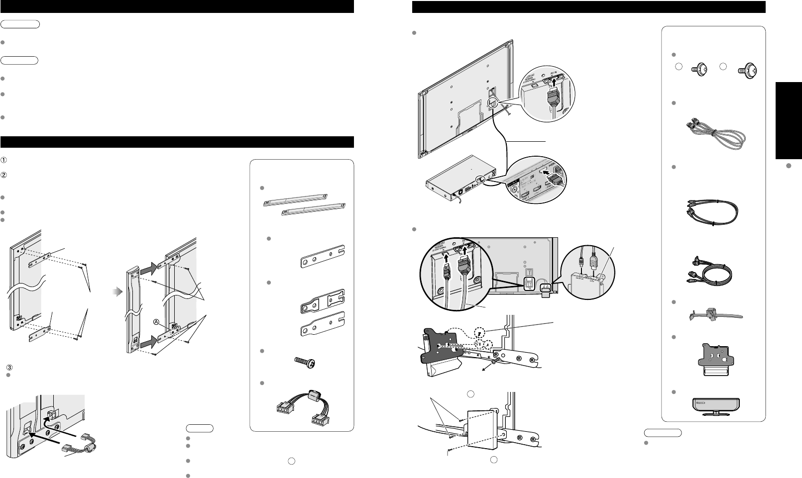
Attaching the Speaker to TV
Fix the Mounting bracket securely to the back of the Display unit with
Assembly screws (total 16 screws).
Insert the speaker mounting screws temporarily in the screw outermost holes
of the speaker and fix the speaker mounting screws to the speaker mounting
bracket.
Orient the front side of the Mounting bracket toward the rear side of the
speaker and display Unit side.
Fix it same as the speaker at the other side.
There will be a gap between the Display Unit and the speaker.
Mounting
bracket
[Bottom]
Assembly
screws
Back of
Display Unit
Mounting bracket
[Top]
Assembly
screws
Back of
Display Unit
Speaker
Place the temporarily
inserted screws into the
counter sunk holes
on the bracket
Connect Display Unit and speaker with speaker cable.
Fix it in the same way as the speaker on the other side.
Lower right
(Back of Display Unit)
Speaker cable
Speaker
Note
Tighten the screws firmly.
Insert to the end of the speaker cable terminal
firmly.
Loosen the screw shown in fig.
A
above to adjust
the gap between the speaker and the display Unit.
Do not hold the speaker to transport the unit.
Connecting Display Unit, Tuner Box and Wireless Unit
Wired connection
Connect Display Unit to Tuner Box
HDMI AV OUT
HDMI AV OUT
Display Unit
Tuner
Box
HDMI Cable
Wireless connection
Connect Wireless Unit (Receiver) to Display Unit
Exclusive cable for Wireless Receiver
Hole for Cable
clamper
Remove this screw when
attaching the speaker.
Insert the metal tab on the
top of the Wireless Unit
(Receiver) into the groove of
the display Unit.
Insert the tabs on the front of
the Wireless Unit (Receiver)
into the holes at the back of
the Display Unit.
Assembly screws
B
Assembly screws
A
Fix securely with assembly
screws (Total 3 screws). Caution
Do not disassemble or modify the
Wireless Unit.
12 13
Quick Start
Guide Accessories/Optional Accessory
Accessories/Optional Accessory
(Continued)
Installing the Display Unit and Tuner Box
Note
Do not connect any other device than Wireless Unit to the HDMI terminal of the Display Unit/Tuner Box.
If the connection is not correct, the following icons will be displayed when the Display unit and the Tuner box are
turned on.
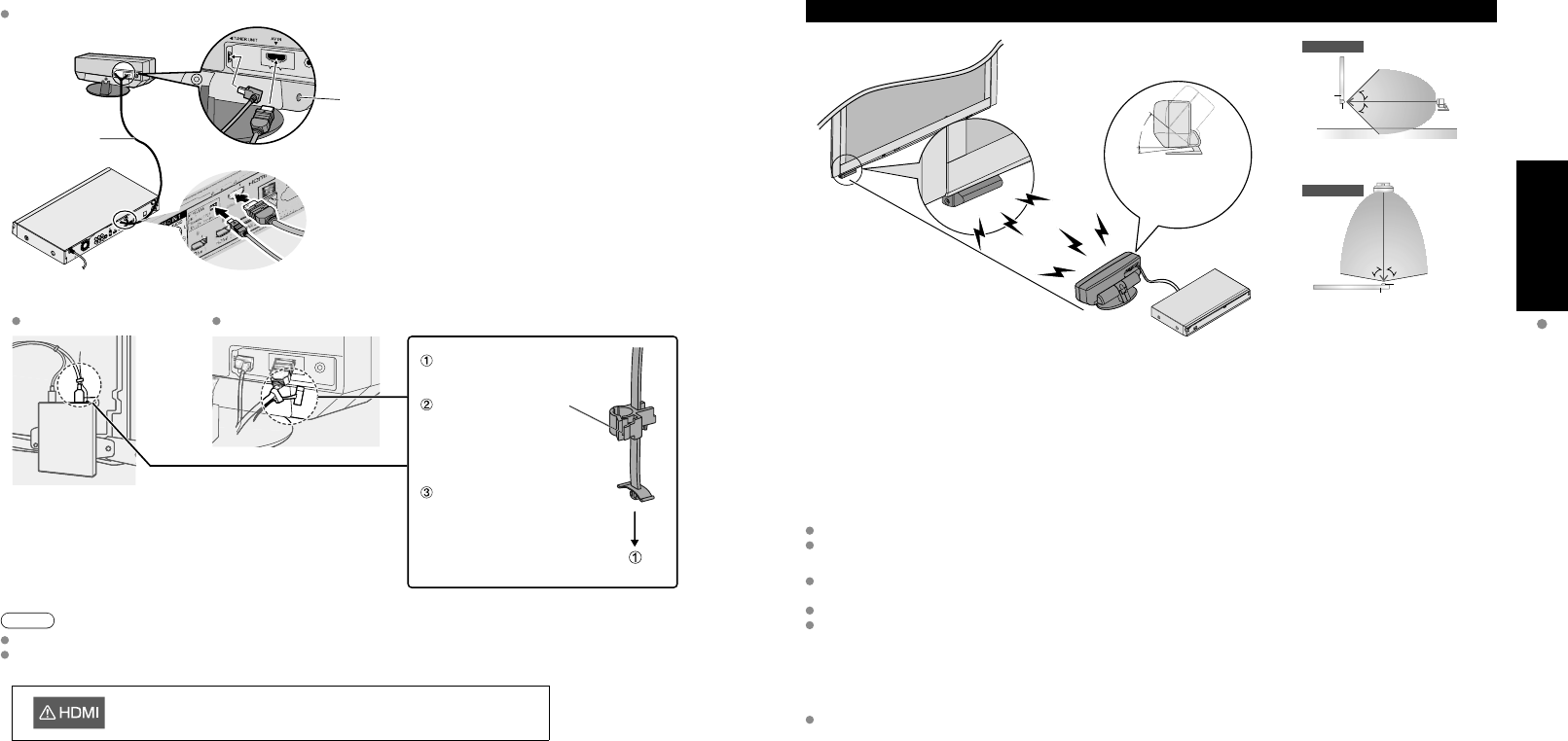
Precautions for Wireless Unit
Transmission Range
Use the Wireless Unit (Transmitter) within a straight line distance of 10 m (approx.) from the Wireless Unit (Receiver).
The range may be shortened if there are any obstacles or the surrounding environment or building structure affects
the transmission.
Installation Environment
Do not install this apparatus in the following locations to avoid distortion of image or audio or unit failure due to the
radio performance degradation.
Location subject to be high temperature (near the heater etc.)
Location with poor air circulation (at the end of a closed rack etc.)
In the following cases, the image or audio may be distorted or intermittent, or the apparatus may not operate properly
:
There is a strong obstacle for the radio waves between the Wireless Unit (Transmitter) and Wireless Unit (Receiver).
(furniture, AV devices, rack, rack door etc.)
Wireless Unit (Transmitter) is not facing the Wireless Unit (Receiver).
Wireless Unit (Transmitter) is placed significantly far from the front of Wireless Unit (Receiver) direction.
(Especially in a high position near the TV display, behind the TV, behind the right side of the pedestal)
Interference from Other Devices
If the Wireless Unit (Transmitter)/Wireless Unit (Receiver) is too close to other devices, failures such as malfunction
or slow remote control response may occur due to the radio wave interference.
Keep the transmitter away from the following devices as much as possible:
Wireless LAN, Microwaves, Telephones, Other electric devices
Connect Wireless Unit (Transmitter) to Tuner Box
Exclusive cable
for Wireless
Transmitter
Hole for Cable
clamper
Cable Binding for Wireless Unit
Wireless Unit (Receiver) Wireless Unit (Transmitter)
Attach to hole for Cable
clamper
Unlock it and connect
the AV cable out of
the Exclusive cable
for Wireless Receiver/
Transmitter.
Fix the cable so that it will
not become unplugged.
40°
5°
approx. 10 m
The angle of the
transmitter can be adjusted
to 40º upward and 5º
downward.
Top View
[Horizontal Direction]
Side View
80°80°
10m
5m
5m Receiver
Display
Transmitter
[Vertical Direction]
Floor
5m
5m
Display 45°
45°
Transmitter
Receiver
This Display Unit is connected to a device other than Tuner Box.
14 15
Quick Start
Guide Basic Connection (Antenna + TV)
Accessories/Optional Accessory
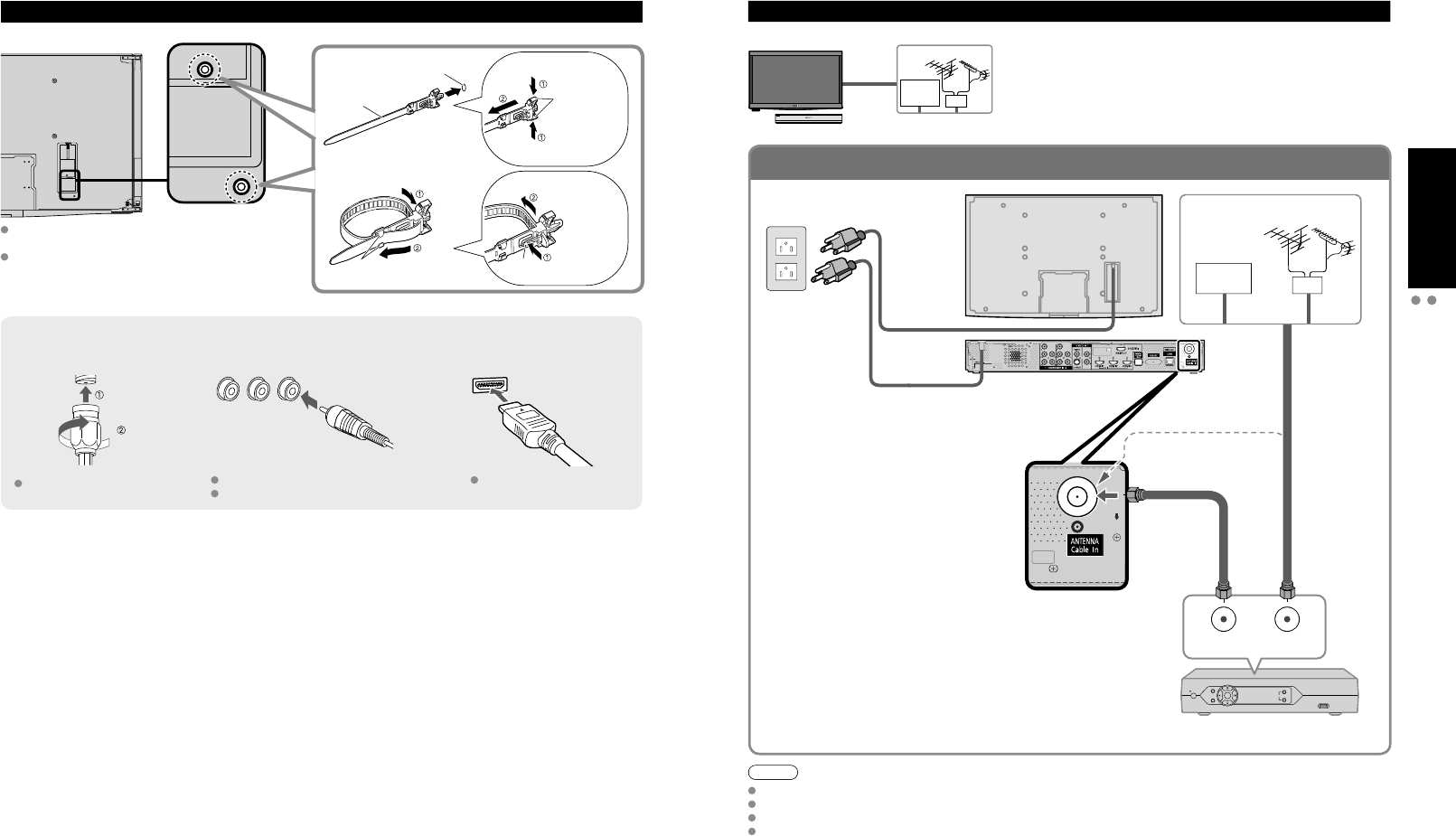
To connect the antenna terminal and Cable Box
ANT OUT ANT IN
Basic Connection
Note
Not all cables and external equipment shown in this book are supplied with the TV.
For more details on the external equipment’s connections, please refer to the operating manuals for the equipment.
When disconnecting the power cord, be absolutely sure to disconnect the power cord plug from the wall outlet first.
For additional assistance, visit us at: www.panasonic.com
www.panasonic.ca
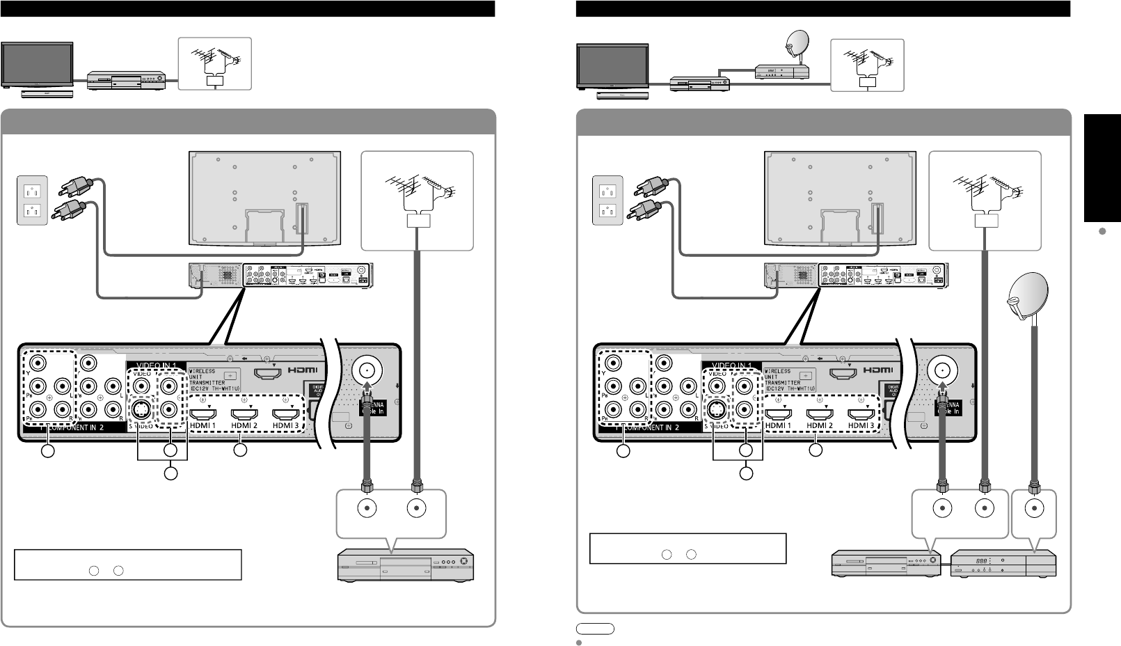
Example 1 Connecting Antenna (To watch TV)
Cable TV
VHF/UHF Antenna
TV VHF/UHF Antenna
•NTSC (National Television System Committee):
Conventional broadcasting
•ATSC (Advanced Television Systems Committee):
Digital TV Standards include digital high-definition television
(HDTV), standard-definition television (SDTV), data broadcasting,
multi-channel surround-sound audio and interactive television.
(If no Cable Box)
AC Cord
(Connect after
all the other
connections have
been made.)
Cable TV
AC 120 V
60 Hz VHF/UHF Antenna
Cable Box
or
or
Accessories/Optional Accessory
(Continued)
Cable Binding Instructions
Antenna terminal Pin terminals HDMI terminal
greenbluered
green
Firmly tighten by hand. Match colors of plugs and terminals.
Insert firmly. Insert firmly.
Reference of connection
Cable Box/Cable
•You need to subscribe to a cable TV service to enjoy viewing their
programming.
•If using a Cable Box set the TV channel to CH3 or CH4 for regular cable.
•You can enjoy high-definition programming by subscribing to a high-
definition cable Service.
The connection for high-definition can be done with the use of HDMI or
Component Video cable. (p. 18)
•To view high-definition programming select the correct video input. (p. 32)
To attach hole
Insert
To bundle
To remove
To loosen
Keep pushing
both sides until
they snap
Snaps
Set
hooks knob Keep pushing
the knob
Cable clamper
Fasten the cables with the Cable clamper as
necessary.
When using the options, follow the option’s
assembly manual to fix cables.
16 17
Quick Start
Guide Basic Connection (TV + DVD Recorder or VCR + Satellite Receiver)
(TV + DVD Recorder or VCR)
To connect the antenna terminal and DVD recorder or VCR
To connect the antenna terminal and Satellite Receiver and DVD recorder or VCR
ANT OUT ANT IN
HDMI AV OUT
BDA
C
HDMI AV OUT
ANT IN
ANT OUT ANT IN
BDA
C
Basic Connection (Continued)
Example 2 Connecting DVD recorder (VCR) (To record/playback)
DVD Recorder
If the source has a higher resolution signal (480p/720p/
1080i/1080p), connection can be made with the use of
a Component Video or HDMI cable. (p. 18)
VCR
Connection can be made with the use of an RF cable
and Composite Video/S Video cable. (p. 18)
VHF/UHF Antenna
TV AV Equipment
(e.g. DVD Recorder
or VCR)
AC Cord
AC 120 V
60 Hz VHF/UHF Antenna
AV Equipment
(e.g. DVD Recorder or VCR)
(with TV tuner)
Connecting TV and AV equipment
Please refer to
A
-
D
on p. 18
Example 3 Connecting DVD recorder (VCR) and satellite receiver
DVD Recorder
or
VCR
Satellite
Receiver
TV
VHF/UHF Antenna
You can enjoy high-definition
programming by subscribing to
high-definition satellite service.
Connection can be done with the
use of HDMI or Component Video
cable. (p. 18)
Note
For details of external equipment connections, please refer to the operating manuals for the equipment.
Satellite ReceiverDVD Recorder or VCR
(with TV tuner)
VHF/UHF Antenna
Connecting TV and AV equipment
Please refer to
A
-
D
on p. 18.
AC Cord
AC 120 V
60 Hz
18 19
Quick Start
Guide Identifying Controls
Basic Connection (AV cable connections)
High-Definition
Standard-Definition
Note
Some programs contain a copyright protection signal to prevent recording.
When the copyright protection program is displayed, do not connect the other TV monitor through a VCR. Video signals fed
through VCRs may be affected by copyright protection systems and the picture will be distorted on the other TV monitor.
For more details on the external equipment’s connections, please refer to the operating manuals for the equipment.
CH
S VIDEO
VIDEO
VIDEO IN 2
L-AUDIO-R
VOL
INPUT/OK
MENU
POWER
HDMI AV OUT
HDMI AV OUT
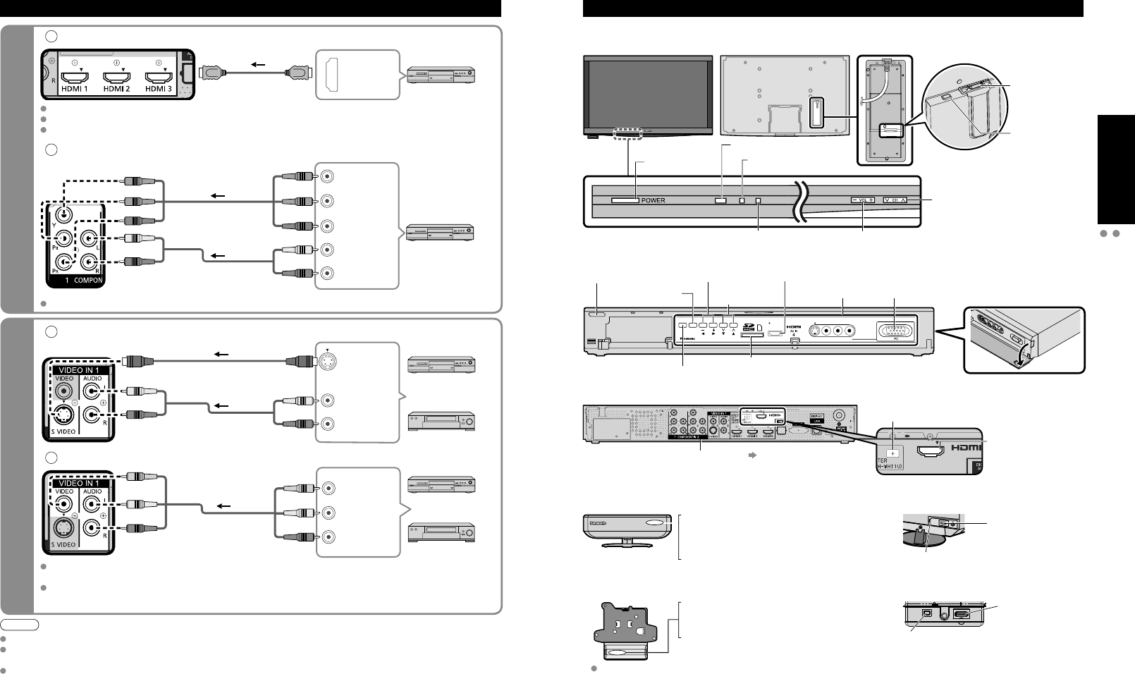
Basic Connection (Continued) Identifying Controls
Power button
HDMI terminal
(For Tuner Box
or Wireless Unit
connection)
Front of Display Unit
A
To use HDMI terminals
HDMI AV OUT
HDMI
AV OUT
e.g. Blu-ray Disc player
AV Equipment
Connecting to HDMI terminals will enable you to enjoy high-definition digital images and high-quality sound.
The HDMI connection is required for a 1080p signal.
For “VIERA LinkTM connections”, please refer to p. 45.
B
To use COMPONENT terminals
L
R
Y
P
B
P
R
COMPONENT
VIDEO OUT
AUDIO
OUT
white
red
green
blue
red
white
red
green
blue
red
white
red
green
blue
red e.g. Blu-ray Disc
player
AV Equipment
Recorders may also be connected to COMPOSITE or S VIDEO terminals. (see below)
C
To use S VIDEO terminals
L
R
white
red
white
red AUDIO
OUT
S VIDEO
OUT
white
red
or
e.g. DVD Recorder
AV Equipment
e.g. VCR
D
To use COMPOSITE terminals
L
R
COMPOSITE
OUT
yellow
white
red
yellow
white
red
yellow
white
red
or
e.g. DVD Recorder
AV Equipment
e.g. VCR
The S Video input will override the composite video signal when S Video cable is connected. Connect
either S Video or Video cable.
Connecting to S VIDEO terminals will enable you to enjoy greater picture quality than using Composite
terminals.
AV cable connections TV controls/indicators
Display Unit Back of Display Unit
DC terminal
(For Wireless
Unit connection)
Front of Tuner Box
Tuner Box
Back of Tuner Box
HDMI 4 terminal VIDEO IN 2
terminals PC terminal
SD card slot
Other terminals p. 62
DC terminal
(For Wireless Unit connection)
HDMI AV OUT terminal
(For Display Unit
or Wireless Unit
connection)
Front of Wireless Unit (Transmitter)
Wireless Unit
Front of Wireless Unit (Receiver)
Back of Wireless Unit (Transmitter)
Back of Wireless Unit (Receiver)
AV terminal
(For Tuner Box
connection)
AV terminal
(For Display Unit
connection)
DC terminal
(For Tuner Box connection)
DC terminal
(For Display Unit connection)
Off: Power off
Red: Power on and no communication
Green: Power on and communication state good
Orange: Power on and communication state not good
Red (blinking): Indicates malfunction
Off: Power off
Red: Power on and no communication
Green: Power on and communication state good
Red (blinking): Indicates malfunction
Changes the input mode
Chooses menu and submenu entries.
Displays the Main
menu.
Volume up/down
Selects channels
in sequence
Power button
Remote control sensor
C.A.T.S. sensor. (Contrast
Automatic Tracking System).
Power indicator
(on: red, off: no light)
When the red LED is blinking, unplug the Exclusive cable for Wireless
Receiver /Transmitter and consult your local Panasonic dealer.
Volume up/down
Selects channels in
sequence
20 21
Quick Start
Guide First Time Setup
Identifying Controls
V
I
E
R
A
C
A
S
T
V
I
E
R
A
T
O
O
L
S
V
I
E
R
A
L
i
n
k
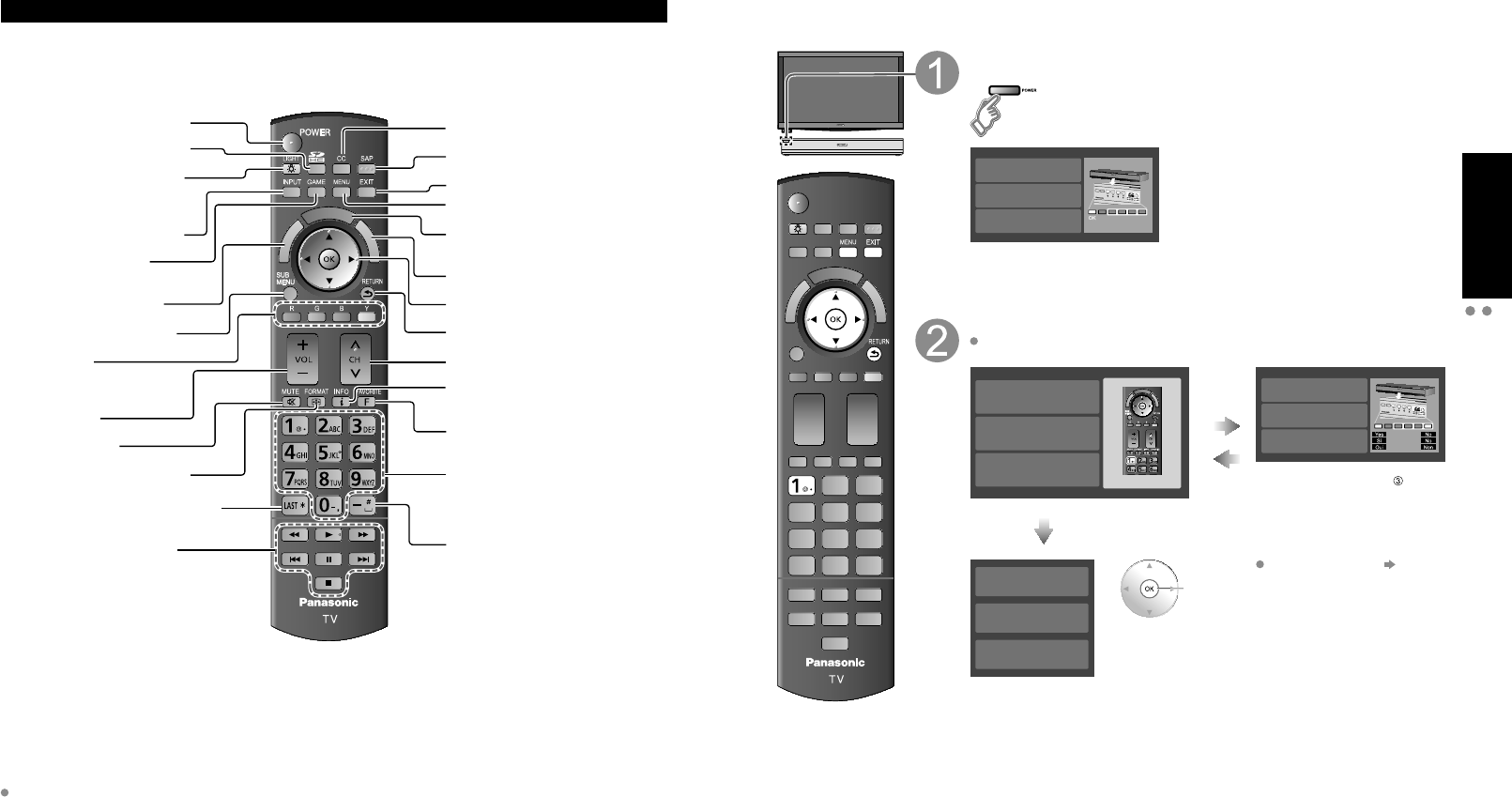
Remote control
Switches TV On or Off (Standby)
Viewing from SD Card (p. 28-31)
Lights the CH and VOL buttons
for 5 seconds. Press again to turn
off the CH and VOL button lights.
Changes the input mode (p. 32)
Switches to input terminal
that has “GAME” label. (p. 32)
VIERA Link menu (p. 48-49)
Displays Sub Menu (p. 25, 42)
Colored buttons
(used for various functions)
(for example, p. 24, 28, 48)
Volume up/down
Sound mute On/Off
Changes aspect ratio (p. 26, 64)
Switches to previously viewed channel
or input modes.
External equipment operations
(p. 49)
Closed caption On/Off (p. 25)
Selects Audio Mode for TV viewing (p. 25)
Exits from menu screen
Displays Main Menu (p. 40)
Displays VIERA CAST screen (Home
screen) (p. 34)
Displays VIERA TOOLS (p. 27)
Selects/OK/Change
Returns to previous menu
Channel up/down
Displays or removes the channel
banner (p. 26)
Operates the Favorite channel list
function. (p. 26)
Numeric keypad to select any channel
(p. 25) or press to enter alphanumeric
input in menus. (p. 24, 32, 36, 38, 48,
50, 52, 54, 56, 59, 60)
Use for digital channels. (p. 25)
First Time Setup (Remote registration)
Make sure to register your remote control with the following procedure when the TV is turned on for the
first time.
Turn the TV On with the POWER button (Tuner Box)
(The display Unit power will be also turned on).
(Tuner Box)
Registration failed.
Try registration again
Enregistrement chou .
Enregistrer de nouveau
Registration failed.
Try registration again
CH
VOL
INPUT/OK
MENU
Confirmation screen will be displayed.
Press the ‘OK’ button and the ‘1’ button
If there is no registered remote control, the “Remote registration” screen is
displayed every time the TV is turned on.
V
I
E
R
A
C
A
S
T
V
I
E
R
A
T
O
O
L
S
V
I
E
R
A
L
i
n
k
Remote registration
Press the ‘OK’ button and the ‘1’ button
simultaneously for at least 3 seconds.
Remote registration
Press the ‘OK’ button and the ‘1’ button
simultaneously for at least 3 seconds.
Enregistrement de la t l commande
Appuyez simultan ment sur les
touches ‘OK’ et ‘1’ pendant au moins
3 secondes.
Error or
Time out
(30 sec)
Registration failed.
Try registration again
Enregistrement chou .
Enregistrer de nouveau
Registration failed.
Try registration again
CH
VOL
INPUT/OK
MENU
Select
“Yes” You can also go to step
selecting “No”.
(Use control panel of Tuner Box,
when Remote control is not
available)
Succeed
Remote registration
completed successfully.
Press OK.
Remote registration
completed successfully.
Press OK.
Enregistrement de la t l commande
r ussi.
Appuyez sur OK.
ok
Remote registration (p. 61)
Identifying Controls (Continued)
This TV uses a RF remote control.
The remote control is operable when it is not facing the Display Unit or Tuner Box.
As the radio waves reflect on walls or other obstacles, the remote control is operable even there are obstacles
between the remote control and the Tuner Box.
Transmission Range
Use the RF remote control within the range of 7 m from the TV tuner.
The range may be shortened if there are any obstacles or the surrounding environment or building structure affects
the transmission.
Interference from Other Devices
If the TV tuner is too close to another device, failures such as malfunction or slow remote control response may occur
due to the radio wave interference.
Keep the transmitter away from the following devices as much as possible:
Wireless LAN, Microwaves, Telephones, Other electric devices
68 69
FAQs, etc.
Specifications
Technical Information Care and Cleaning
TC-P54Z1
Power Source AC 120 V, 60 Hz
Power
Consumption
Maximum Display Unit: *** W / Tuner Box: *** W
(Wireless Unit (Receiver) 12 W / Wireless Unit (Transmitter) 10 W)
Standby condition Display Unit: *.* W / Tuner Box: *.* W
Plasma
Display panel
Drive method AC type
Aspect Ratio 16:9
Visible screen size
(W × H × Diagonal)
(No. of pixels)
54 ” class (54.1 inches measured diagonally)
47.1 ” × 26.5 ” × 54.1 ” (1,198 mm × 673 mm × 1,473 mm)
2,073,600 (1,920 (W) × 1,080 (H)) [5,760 × 1,080 dots]
Sound
Audio Output 20 W [(3 W + 7 W) × 2] (10 % THD)
PC signals VGA, SVGA, XGA, WXGA, SXGA
Horizontal scanning frequency 31 - 69 kHz
Vertical scanning frequency 59 - 86 Hz
Channel Capability
(Digital/Analog) VHF/UHF: 2 - 69, CATV: 1 - 135
Operating Conditions Temperature: 32 °F – 104 °F (0 °C – 40 °C)
Humidity: 20 % – 80 % RH (non-condensing)
Connection Terminals
VIDEO IN 1 VIDEO: RCA PIN Type × 1 1.0 V [p-p] (75 )
S-VIDEO: Mini DIN 4-pin Y: 1.0 V [p-p] (75 ) C: 0.286 V [p-p] (75 )
AUDIO L-R: RCA PIN Type × 2 0.5 V [rms]
VIDEO IN 2 VIDEO: RCA PIN Type × 1 1.0 V [p-p] (75 )
AUDIO L-R: RCA PIN Type × 2 0.5 V [rms]
COMPONENT IN 1-2 Y: 1.0 V [p-p] (including synchronization)
PB, PR: ±0.35 V [p-p]
AUDIO L-R: RCA PIN Type × 2 0.5 V [rms]
HDMI 1-4 TYPE A Connector × 4
• This TV supports “HDAVI Control 4” function.
PC D-SUB 15PIN: R,G,B / 0.7 V [p-p] (75 )
HD, VD / 1.0 - 5.0 V [p-p] (high impedance)
RS232C (Serial) D-sub 9pin for external control
LAN (for VIERA CAST IPTV)
RJ45 (10BASE-T/100BASE-TX)
Card slot SD CARD slot × 1
AUDIO OUT AUDIO L-R: RCA PIN Type × 2 0.5 V [rms]
DIGITAL AUDIO OUT PCM / Dolby Digital, Fiber Optic
FEATURES 3D Y/C FILTER CLOSED CAPTION
V-Chip IPTV (VIERA CAST)
Photo viewer Movie player HDAVI Control 4
Dimensions
( W × H × D )
Display
Unit
Including pedestal 56.3” × 35.2” × 15.0” (1,428 mm × 893 mm × 379 mm)
Display Unit only 56.3” × 32.3” × 1.0” (1,428 mm × 820 mm × 25 mm)
Tuner Box 17.0” × 2.4” × 9.8” (430 mm × 59 mm × 240 mm)
Wireless Unit (Transmitter)
Wireless Unit (Receiver)
7.5” × 2.8” × 2.8” (190 mm × 69 mm × 70 mm)
5.8” × 5.3” × 1.9” (146 mm × 133 mm × 46 mm)
Mass
Display
Unit
Including pedestal 83.8 lb (38.0 )
Display Unit only 70.6 lb (32.0 )
Tuner Box 6.7 lb (3.0 )
Wireless Unit (Transmitter)
Wireless Unit (Receiver)
0.7 lb (280 )
0.9 lb (400 )
1
678
3945
101514131211
2
Technical Information (Continued)
Care and Cleaning
First, unplug the Power cord plug from the wall outlet.
Display panel
The front of the display panel has been specially treated. Wipe the panel surface gently using only a cleaning cloth or a soft, lint-
free cloth.
If the surface is particularly dirty, soak a soft, lint-free cloth in diluted mild liquid dish soap (1 part mild liquid dish soap diluted
by 100 times the amount of water) and then wring the cloth to remove excess liquid. Use this cloth to wipe the surface of the
display panel, then wipe it evenly with a dry cloth of the same type until the surface is dry.
Do not scratch or hit the surface of the panel with fingernails or other hard objects. Furthermore, avoid contact with volatile
substances such as insect sprays, solvents, and thinner; otherwise, the quality of the surface may be adversely affected.
Cabinet
If the cabinet becomes dirty, wipe it with a soft, dry cloth.
If the cabinet is particularly dirty, soak the cloth in a weak mild liquid dish soap and then wring the cloth dry.
Use this cloth to wipe the cabinet and then wipe it dry with a dry cloth.
Do not allow any mild liquid dish soap to come into direct contact with the surface of the Plasma TV.
If water droplets get inside the unit, operating problems may result.
Avoid contact with volatile substances such as insect sprays, solvents, and thinner; otherwise, the quality of the cabinet surface
may be adversely affected or the coating may peel off. Furthermore, do not leave it for long periods in contact with articles made
from rubber or PVC.
Pedestal
Cleaning
Wipe the surfaces with a soft, dry cloth. If the unit is particularly dirty, clean it using a cloth soaked with water to
which a small amount of mild liquid dish soap has been added and then wipe with a dry cloth.
Do not use products such as solvents, thinner, or household wax for cleaning, as they can damage the surface
coating. (If using a chemically-treated cloth, follow the instructions supplied with the cloth.)
Do not attach sticky tape or labels, as they can make the surface of the pedestal dirty. Do not allow long-term
contact with rubber, vinyl products, or the like. (Doing so will cause deterioration.)
Wireless Unit
Wipe the glossy surface of Transmitter and Receiver gently with the Cleaning cloth (included).
PC Input Terminals Connection
Computer signals which can be input are those with a horizontal scanning frequency of 15 to 110 kHz and vertical scanning frequency
of 48 to 120 Hz. (However, the image will not be displayed properly if the signals exceed 1,200 lines.)
Some PC models cannot be connected to the set.
There is no need to use an adapter for computers with IBM PC/AT compatible D-sub 15P terminal.
The maximum resolution: 1,280 × 1,024
If the display resolution exceeds these maximums, it may not be possible to show fine detail with sufficient clarity.
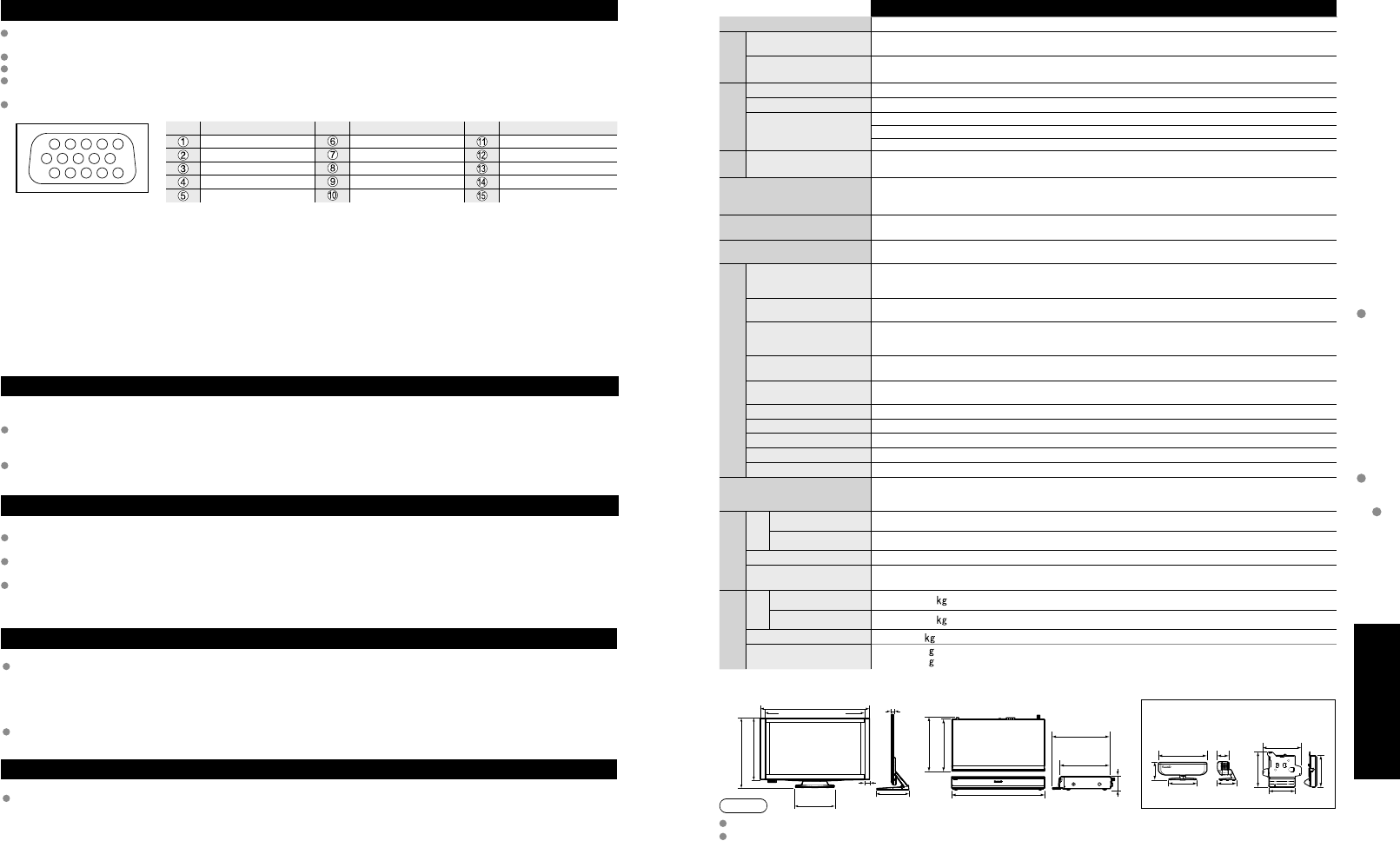
Signal Names for D-sub 15P Connector
Pin No.
Signal Name
Pin No.
Signal Name
Pin No.
Signal Name
R GND (Ground) NC (not connected)
G GND (Ground) NC
B GND (Ground) HD/SYNC
NC (not connected) NC (not connected) VD
GND (Ground) GND (Ground) NC
Pin Layout for PC Input Terminal
Specifications
Note
Design and Specifications are subject to change without notice. Mass and Dimensions shown are approximate.
Dimensions and Mass are the values for a speaker installation.
15.0 ” (379 mm) 17.0 ” (430 mm) 4.4 ” (110 mm) 2.8 ”
(70 mm) 1.9 ” (46 mm)
1.0 ” (25 mm)
2.5 ”
(60 mm)
2.4 ”
(59 mm)
56.3 ” (1,428 mm)
9.5 ”
(240 mm)
10.6 ”
(248 mm) 7.5 ”
(190 mm)
5.8 ”
(146 mm)
1.7 ”
(43 mm)
32.3 ” (820 mm)
35.2 ” (893 mm)
19.7 ”
(500 mm)
9.5 ” (240 mm)
9.8 ” (249 mm)
5.3 ” (133 mm)
2.8 ” (69 mm)
4.8 ” (120 mm)
51.3” (1,302 mm)
[TC-P54Z1]
Display Unit Tuner Box Wireless Unit
(Transmitter) (Receiver)