Panasonic AJ HD1700 User Manual To The Ceb0c33f 1fab 4811 96e6 3330017ab52c
User Manual: Panasonic AJ-HD1700 to the manual
Open the PDF directly: View PDF ![]() .
.
Page Count: 134 [warning: Documents this large are best viewed by clicking the View PDF Link!]
Thank you for purchasing this product.
Before operating this product, please read the instructions carefully and save this manual for future use.
Model AJ-
Operating Instructions
Digital HD
Video Cassette Recorder
VQT0E88
P
E
WARNING:
•
TO REDUCE THE RISK OF FIRE OR
SHOCK HAZARD, DO NOT EXPOSE THIS
EQUIPMENT TO RAIN OR MOISTURE.
• TO REDUCE THE RISK OF FIRE OR SHOCK
HAZARD, KEEP THIS EQUIPMENT AWAY
FROM ALL LIQUIDS—USE AND STORE
ONLY IN LOCATIONS WHICH ARE NOT
EXPOSED TO THE RISK OF DRIPPING OR
SPLASHING LIQUIDS, AND DO NOT PLACE
ANY LIQUID CONTAINERS ON TOP OF THE
EQUIPMENT.
2
For your safety (General)
indicates safety information.
CAUTION:
TO REDUCE THE RISK OF FIRE OR SHOCK
HAZARD AND ANNOYING INTERFERENCE,
USE THE RECOMMENDED ACCESSORIES
ONLY.
CAUTION:
TO REDUCE THE RISK OF FIRE OR SHOCK
HAZARD, REFER MOUNTING OF THE
OPTIONAL BOARD AND CHANGE OF
SWITCH SETTINGS INSIDE THE UNIT TO
QUALIFIED SERVICE PERSONNEL.
CAUTION:
Do not install or place this unit in a bookcase,
built-in cabinet or any other confined space in
order to maintain adequate ventilation. Ensure
that curtains and any other materials do not
obstruct the ventilation to prevent risk of
electric shock or fire hazard due to
overheating.
CAUTION:
EVEN WHEN THE POWER SWITCH IS IN
THE OFF POSITION, A SMALL CURRENT
FLOWS THE FILTER CIRCUIT.
CAUTION:
THE AC OUTLET (MAINS SOCKET) SHALL
BE INSTALLED NEAR THE EQUIPMENT AND
SHALL BE EASILY ACCESSIBLE.
THIS APPARATUS MUST BE GROUNDED
To ensure safe operation the three-pin plug must be
inserted only into a standard three-pin power outlet
(socket) which is effectively grounded through the
normal household wiring.
Extension cords used with the equipment must be
three-core and be correctly wired to provide
connection to the ground. Incorrectly wired extension
cords can be extremely hazardous.
The fact that the equipment operates satisfactorily
does not imply that it is grounded, and the installation
is not necessarily safe. For your safety, if in any
doubt about the effective grounding of the equipment
or power outlet (socket), please consult a qualified
electrician.
Operating precaution
Operation near any appliance which generates
strong magnetic fields may give rise to noise in
the video and audio signals. If this should be the
case, deal with the situation by, for instance,
moving the source of the magnetic fields away
from the unit before operation.
CAUTION:
This apparatus can be operated at a voltage in the
range of 100 – 240 V AC.
Voltage other than 120 V is not intended for U.S.A.
and Canada.
CAUTION:
Operation at a voltage other than 120 V AC may
require the use of a different AC plug. Please contact
either a local or foreign Panasonic authorized service
center for assistance in selecting an alternate AC
plug.
3
For your safety
CAUTION
RISK OF ELECTRIC SHOCK
DO NOT OPEN
CAUTION: TO REDUCE THE RISK OF ELECTRIC SHOCK,
DO NOT REMOVE COVER (OR BACK).
NO USER SERVICEABLE PARTS INSIDE.
REFER TO SERVICING TO QUALIFIED SERVICE PERSONNEL.
The lightning flash with arrowhead symbol,
within an equilateral triangle, is intended to
alert the user to the presence of uninsulated
“dangerous voltage” within the product’s
enclosure that may be of sufficient
magnitude to constitute a risk of electric
shock to persons.
The exclamation point within an equilateral
triangle is intended to alert the user to the
presence of important operating and
maintenance (service) instructions in the
literature accompanying the appliance.
For U.S.A. and Canada
FCC Note:
This device complies with Part 15 of the FCC Rules.
To assure continued compliance follow the attached
installation instructions and do not make any
unauthorized modifications.
This equipment has been tested and found to comply
with the limits for a class A digital device, pursuant to
Part 15 of the FCC Rules. These limits are designed
to provide reasonable protection against harmful
interference when the equipment is operated in a
commercial environment. This equipment generates,
uses, and can radiate radio frequency energy and, if
not installed and used in accordance with the
instruction manual, may cause harmful interference
to radio communications. Operation of this equipment
in a residential area is likely to cause harmful
interference in which case the user will be required to
correct the interference at his own expense.
For Europe
CAUTION:
DO NOT REMOVE PANEL COVER BY UN-
SCREWING
To reduce the risk of electric shock, do not remove
cover. No user serviceable parts inside.
indicates safety information.
Notice (U.S.A. only):
This product has a fluorescent lamp that contains
a small amount of mercury. It also contains lead
in some components. Disposal of these materials
may be regulated in your community due to
environmental considerations. For disposal or
recycling information please contact your local
authorities, or the Electronics Industries Alliance:
<http://www.eiae.org.>
4
FOR U.K. ONLY
This appliance is supplied with a moulded three pin
mains plug for your safety and convenience.
A 13 amp fuse is fitted in this plug.
Should the fuse need to be replaced please ensure that
the replacement fuse has a rating of 13 amps and that it
is approved by ASTA or BSI to BS1362.
Check for the ASTA mark Ïor the BSI mark Ìon the
body of the fuse.
If the plug contains a removable fuse cover you must
ensure that it is refitted when the fuse is replaced.
If you lose the fuse cover the plug must not be used
until a replacement cover is obtained.
A replacement fuse cover can be purchased from your
local Panasonic Dealer.
IF THE FITTED MOULDED PLUG IS UNSUITABLE
FOR THE SOCKET OUTLET IN YOUR HOME THEN
THE FUSE SHOULD BE REMOVED AND THE PLUG
CUT OFF AND DISPOSED OF SAFELY. THERE IS A
DANGER OF SEVERE ELECTRICAL SHOCK IF THE
CUT OFF PLUG IS INSERTED INTO ANY 13 AMP
SOCKET.
If a new plug is to be fitted please observe the wiring
code as shown below.
If in any doubt please consult a qualified electrician.
WARNING: THIS APPLIANCE MUST BE EARTHED.
IMPORTANT: The wires in this mains lead are coloured
in accordance with the following code:
Green-and-Yellow: Earth
Blue: Neutral
Brown: Live
Caution for AC Mains Lead
As the colours of the wires in the mains lead of this
appliance may not correspond with the coloured
markings identifying the terminals in your plug, proceed
as follows:
• The wire which is coloured GREEN-AND-YELLOW
must be connected to the terminal in the plug which
is marked with the letter E or by the Earth symbol Ó
or coloured GREEN or GREEN-AND-YELLOW.
• The wire which is coloured BLUE must be connected
to the terminal in the plug which is marked with the
letter N or coloured BLACK.
• The wire which is coloured BROWN must be
connected to the terminal in the plug which is marked
with the letter L or coloured RED.
FOR YOUR SAFETY PLEASE READ THE FOLLOWING TEXT CAREFULLY.
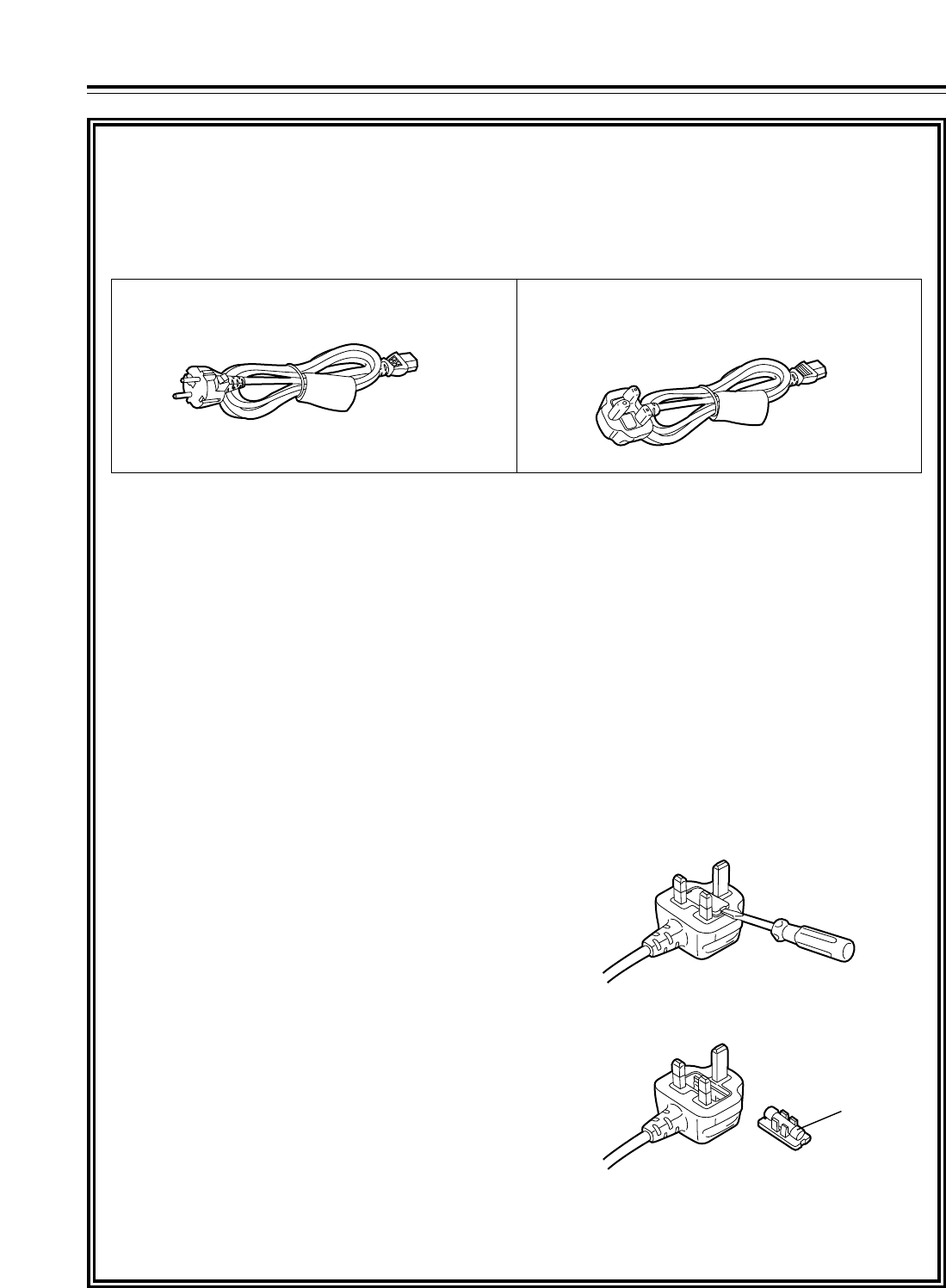
This product is equipped with 2 types of AC mains cable. One is for continental Europe, etc. and the other one is only
for U.K.
Appropriate mains cable must be used in each local area, since the other type of mains cable is not suitable.
FOR CONTINENTAL EUROPE, ETC.
Not to be used in the U.K. FOR U.K. ONLY
If the plug supplied is not suitable for your socket
outlet, it should be cut off and appropriate one fitted.
How to replace the fuse
1. Open the fuse compartment with a screwdriver.
2. Replace the fuse.
Fuse
For your safety

5
Contents
For your safety . . . . . . . . . . . . . . . . . . . . . . . . . . . . .2
General outline . . . . . . . . . . . . . . . . . . . . . . . . . . . .6
Standard accessories . . . . . . . . . . . . . . . . . . . . . . .6
Features . . . . . . . . . . . . . . . . . . . . . . . . . . . . . . . . . .7
Parts and Their Functions . . . . . . . . . . . . . . . . . . .8
OFront panel . . . . . . . . . . . . . . . . . . . . . . . . . . . .8
OTime code display . . . . . . . . . . . . . . . . . . . . . .16
ORear panel . . . . . . . . . . . . . . . . . . . . . . . . . . . .18
Connections . . . . . . . . . . . . . . . . . . . . . . . . . . . . . .20
OExample of connections performed for
one VTR . . . . . . . . . . . . . . . . . . . . . . . . . . . . .20
OExample of connections performed for
two VTRs (deck-to-deck) . . . . . . . . . . . . . . . . .20
OExample of system connections in
23/24 Hz or 25 Hz (HD) mode . . . . . . . . . . . . .21
OExample of system connections in
25 Hz (SD) mode . . . . . . . . . . . . . . . . . . . . . . .21
OExample of connections with an
editing controller . . . . . . . . . . . . . . . . . . . . . . .22
Concerning tapes . . . . . . . . . . . . . . . . . . . . . . . . .23
Turning on the power and inserting
the cassette . . . . . . . . . . . . . . . . . . . . . . . . . . . . . .24
STOP and STANDBY modes . . . . . . . . . . . . . . . . .24
Recording . . . . . . . . . . . . . . . . . . . . . . . . . . . . . . . .25
Playback . . . . . . . . . . . . . . . . . . . . . . . . . . . . . . . . .26
Jog/shuttle . . . . . . . . . . . . . . . . . . . . . . . . . . . . . . .27
Manual editing . . . . . . . . . . . . . . . . . . . . . . . . . . . .28
Preroll . . . . . . . . . . . . . . . . . . . . . . . . . . . . . . . . . . .28
Automatic editing (deck-to-deck) . . . . . . . . . . . . .29
OSwitch settings and adjustments . . . . . . . . . . .29
OSelecting the editing mode . . . . . . . . . . . . . . .30
ORegistering the edit points . . . . . . . . . . . . . . . .30
OChecking the edit points . . . . . . . . . . . . . . . . .31
OModifying edit points . . . . . . . . . . . . . . . . . . . .31
OPreviewing . . . . . . . . . . . . . . . . . . . . . . . . . . . .32
OAutomatic editing . . . . . . . . . . . . . . . . . . . . . . .32
OReviewing . . . . . . . . . . . . . . . . . . . . . . . . . . . .33
Audio split editing . . . . . . . . . . . . . . . . . . . . . . . . .34
Variable memory function . . . . . . . . . . . . . . . . . . .36
Function menus . . . . . . . . . . . . . . . . . . . . . . . . . . .38
OGeneral description . . . . . . . . . . . . . . . . . . . . .38
OAllocating the function keys . . . . . . . . . . . . . . .39
OHow to switch the settings . . . . . . . . . . . . . . . .40
OHOME . . . . . . . . . . . . . . . . . . . . . . . . . . . . . . .41
OVIDEO . . . . . . . . . . . . . . . . . . . . . . . . . . . . . . .47
OAUDIO . . . . . . . . . . . . . . . . . . . . . . . . . . . . . . .49
OTC . . . . . . . . . . . . . . . . . . . . . . . . . . . . . . . . . .51
OCUE . . . . . . . . . . . . . . . . . . . . . . . . . . . . . . . . .52
ODIAG . . . . . . . . . . . . . . . . . . . . . . . . . . . . . . . .55
OMENU . . . . . . . . . . . . . . . . . . . . . . . . . . . . . . .57
OASSEMBLE . . . . . . . . . . . . . . . . . . . . . . . . . . .58
OINSERT . . . . . . . . . . . . . . . . . . . . . . . . . . . . . .59
OSETUP MENU/SYSTEM MENU . . . . . . . . . . .60
OFILE . . . . . . . . . . . . . . . . . . . . . . . . . . . . . . . . .62
OPF1/PF2 . . . . . . . . . . . . . . . . . . . . . . . . . . . . .64
OCARD . . . . . . . . . . . . . . . . . . . . . . . . . . . . . . .69
O50P IN/OUT ASSIGN . . . . . . . . . . . . . . . . . . .72
System menus . . . . . . . . . . . . . . . . . . . . . . . . . . . .78
Setup menus . . . . . . . . . . . . . . . . . . . . . . . . . . . . .81
OBASIC . . . . . . . . . . . . . . . . . . . . . . . . . . . . . . .81
OOPERATION . . . . . . . . . . . . . . . . . . . . . . . . . .84
OINTERFACE . . . . . . . . . . . . . . . . . . . . . . . . . .87
OEDIT . . . . . . . . . . . . . . . . . . . . . . . . . . . . . . . .88
OTAPE PROTECT . . . . . . . . . . . . . . . . . . . . . . .90
OTIME CODE . . . . . . . . . . . . . . . . . . . . . . . . . . .91
OVIDEO . . . . . . . . . . . . . . . . . . . . . . . . . . . . . . .93
OAUDIO . . . . . . . . . . . . . . . . . . . . . . . . . . . . . . .98
OMENU . . . . . . . . . . . . . . . . . . . . . . . . . . . . . .104
OConnections with Dolby-E components . . . . .104
OHow to switch the system frequency . . . . . . .105
OSelecting the recording/playback format
and sync signals which support the
operation mode . . . . . . . . . . . . . . . . . . . . . . .105
OMenu management accompanying
switching the system frequency . . . . . . . . . . .106
Time code and user’s bit . . . . . . . . . . . . . . . . . . .111
OTime code . . . . . . . . . . . . . . . . . . . . . . . . . . .111
OUser’s bit . . . . . . . . . . . . . . . . . . . . . . . . . . . .111
OSetting the internal time code . . . . . . . . . . . .111
OSetting the external time code . . . . . . . . . . . .112
OCue time registration, preroll and cue-up
(These functions work only on the HOME,
PF1 and PF2 screens.) . . . . . . . . . . . . . . . . .112
OTime code and user’s bit playback . . . . . . . .112
Superimpose screen . . . . . . . . . . . . . . . . . . . . . .113
Selecting the audio recording channels and
monitor output . . . . . . . . . . . . . . . . . . . . . . . . . . .114
Display saving function . . . . . . . . . . . . . . . . . . .115
Rack mounting . . . . . . . . . . . . . . . . . . . . . . . . . . .116
Video head cleaning . . . . . . . . . . . . . . . . . . . . . .117
Condensation . . . . . . . . . . . . . . . . . . . . . . . . . . . .117
Maintenance . . . . . . . . . . . . . . . . . . . . . . . . . . . . .117
Error messages . . . . . . . . . . . . . . . . . . . . . . . . . .118
ODIAG menu . . . . . . . . . . . . . . . . . . . . . . . . . .118
OWarning messages . . . . . . . . . . . . . . . . . . . .120
OError messages . . . . . . . . . . . . . . . . . . . . . . .120
RS-232C interface . . . . . . . . . . . . . . . . . . . . . . . .122
Connector signals . . . . . . . . . . . . . . . . . . . . . . . .128
Printed circuit boards . . . . . . . . . . . . . . . . . . . . .129
Specifications . . . . . . . . . . . . . . . . . . . . . . . . . . .130

6
General outline
The model AJ-HD1700 is a DVCPRO HD-LP format
HD digital video cassette recorder which uses 1/4˝
wide compact cassette tapes.
It can record, play back and edit 1080/59.94i (60i),
720/59.94p (60p) and 1080/50i HD signals and also
play back existing DVCPRO (25 Mbps or 50 Mbps)
tapes.
It is also capable of converting from sources with a
720/24p over 60p (720/25p over 60p) format recorded
using a variable frame rate camera into a 1080/24psf
(1080/25psf) format and outputting the resulting
signals, thus fulfilling the needs of applications in the
cinema film production field.
Further, the HD-SD conversion facility of its format
converter, which is provided as a standard accessory,
extends the uses of this VTR to encompass
interfacing with existing SD systems and into
configuring of HD systems.
By mobilizing highly efficient digital compression
technology to assure a high picture quality, this VTR
significantly minimizes deterioration in the picture
quality and sound quality during the dubbing process.
It features a compact size of 4U and a lightweight
design that enables it to be carried around with ease,
and to be readily installed in a 19-inch rack.
The equipment is set up using an interactive system
whereby the operator manipulates the function
buttons on the front panel and observes the menu
screens on the front panel’s LED monitor.
In terms of the editing features, this VTR is capable of
both assemble editing and insert editing.
Standard accessories
Power cord (AJ-HD1700P) . . . . . . . . . . . . . . . . . . .1
Power cord (AJ-HD1700E) . . . . . . . . . . . . . . . . . . .2

7
Features
Time codes
This VTR comes with a built-in time code generator
(TCG)/time code reader (TCR).
In addition to the internal time code, an external time code
can also be input and recorded as the LTC on the VTR.
Multi-functional interfaces
• Serial digital input/output connector
The VTR comes with an HD component serial interface
input/output connector. This one BNC connector enables
HD component video signals and 8-channels digital audio
signals to be interfaced. (SMPTE 292M, 299M, BTA S-
004)
It is also equipped with an HD/SD format converter as a
standard accessory so that SD component serial signals
can also be output. (SMPTE 259M-C, 272M-A, 294M)
• Analog video output connector
Composite signals are output during DVCPRO50- or
DVCPRO-compatible playback, DV playback, DVCAM
playback and down-conversion.
• AES/EBU audio input/output connectors
Digital audio input/output connectors for 8 channels are
featured as a standard accessory.
• SDTI input/output connector
Use of the SDTI board (optional accessory) enables
interfacing with the compressed component signals still in
their original form. (SMPTE 305M, 321M)
• SD signal up-conversion and recording
Using the input up-converter board (optional accessory),
SD component serial signals (SMPTE 259M-C) can be
up-converted and recorded as HD signals.
• 9-pin RS-422A and RS-232C remote control
connectors
In addition to the standard 9-pin serial remote (RS-422A)
control connector, the VTR is provided with RS-232C and
50-pin parallel remote control connectors.
The RS-422A facility enables parallel operation if a loop
connection has been established between the VTR and
another VTR.
8-channel high-sound-quality digital audio
The 8-channel PCM audio feature allows for not only
independent editing but mixing as well on all 8 channels.
One channel is provided for the analog cue track.
Menu-driven setup
The setup settings, which are conducted prior to operating
the VTR, are performed while the operator views the setup
menus either on the VTR’s LCD monitor or on a TV monitor.
Multi-functional front panel with LCD monitor
The front panel’s multiple functions, including the LCD
monitor for monitoring images, the function buttons and
large-size display panel, are contained within the 4U
dimensions and designed to improve operating ease.
Compact size and light weight
This is a 4U digital VTR. Using the rack-mounting adapters
(AJ-MA75P: optional accessory), it can also be easily
housed in a 19-inch rack.
Up to 126 minutes of recording
Using the DVCPRO HD-LP recording system, up to 126
minutes of material can be recorded on the newly developed
1/4˝ XL-size cassette tape.
High picture quality
The VTR’s high picture quality is achieved by 4:2:2 HD
component signal recording using a recording rate (100
Mbps) which is 4 times higher than that of the existing
DVCPRO format.
1080i/720p (*1), 59.94 Hz/60 Hz/50 Hz signal
switching
By making menu selections, the signals of the respective
formats can be recorded and played back.
*1: When the system frequency of 50 Hz has been selected,
recording and playback using the 720p format are not possible.
Frame rate conversion function
By making menu selections, the VTR can output signals
after converting them to the 1080/24psf (25psf) format when
it plays back a tape recorded by a variable frame rate
camera at a frame rate of 24fps (25fps).
SDI interface
The VTR comes with an HD serial digital interface as a
standard accessory.
Playback compatibility with DVCPRO systems
Besides DVCPRO HD-LP recording and playback, the VTR
can also play back tapes which have been recorded using
the existing DVCPRO HD, DVCPRO50 and DVCPRO
systems.
Consumer-use DV tapes (SP) and DVCAM tapes can also
be played back on this VTR.
Digital slow motion/dial jog
Panasonic’s unique digital slow motion technology enables
clear playback (of tapes recorded using the DVCPRO HD-
LP system) at speeds ranging from j1kto i2k.
<Note>
Some noise may occur during slow playback (using an
external controller) at speeds of almost exactly j1k or
i2k.
Search speed
Search speed enables tapes (recorded using the HD-LP
system) to be played back with color images at speeds of up
to 100 times in the forward or reverse direction.
8
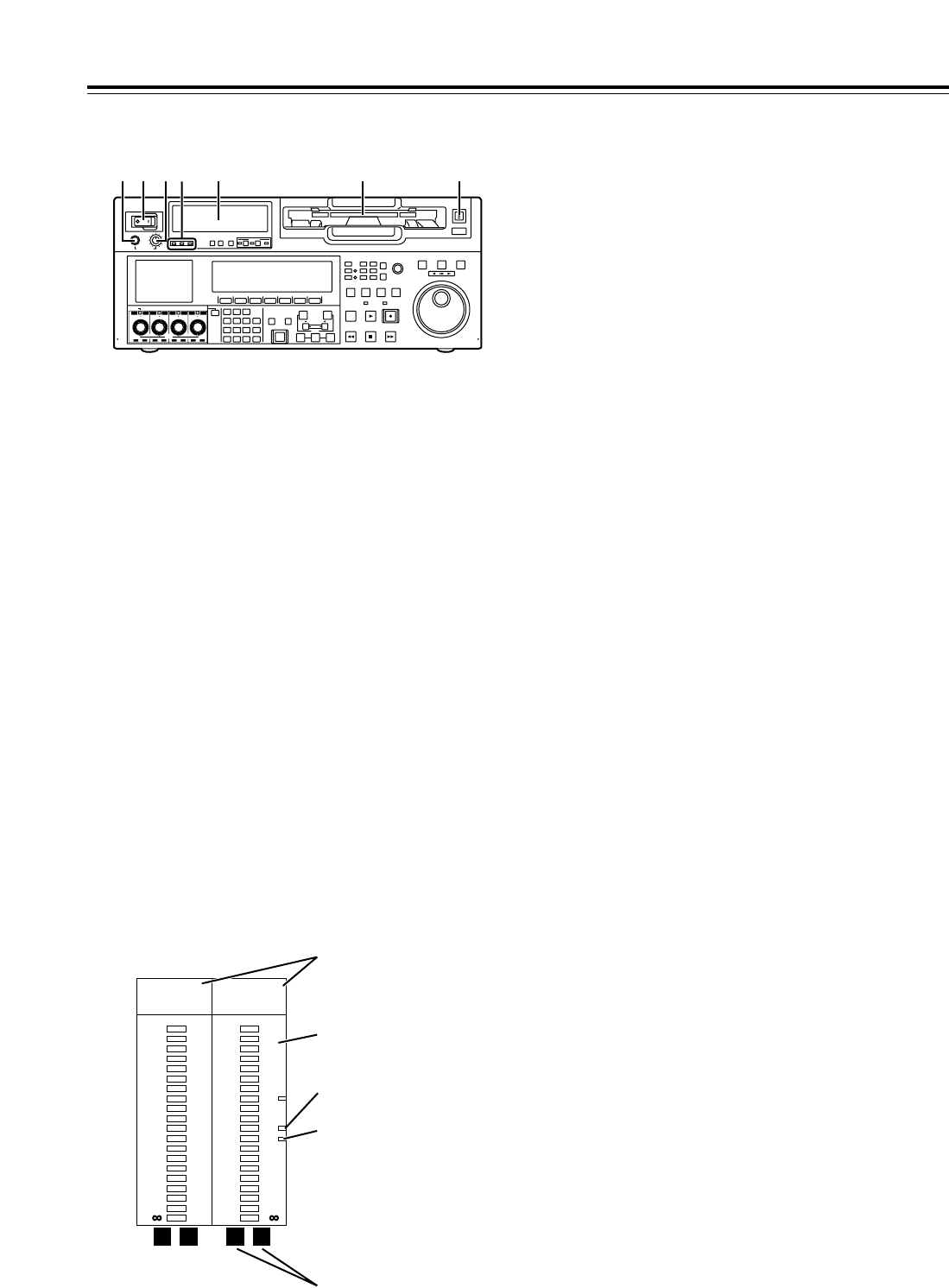
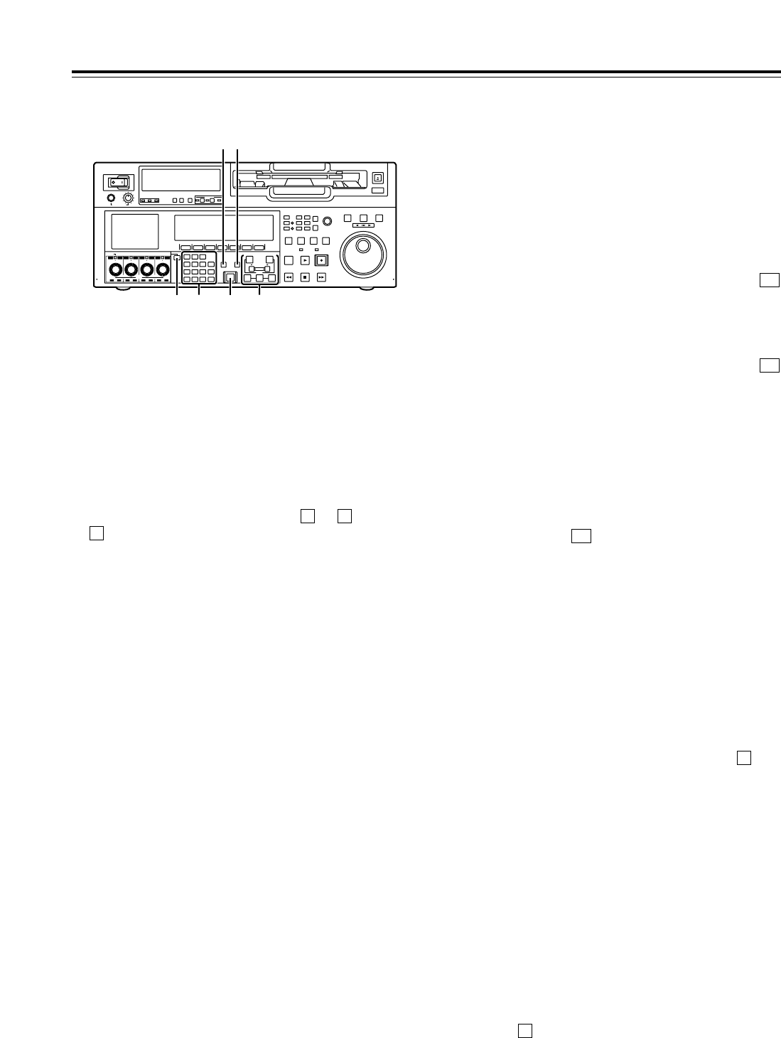
Front panel
1POWER switch
2Audio level meter
The audio information is displayed here.
• The levels of the CH1, CH2, CH3, CH4, CH5,
CH6, CH7 and CH8 PCM audio signals and level
of the CUE track signal are displayed here.
• The levels of the input signals are displayed
during recording and when E-E is selected.
During playback, the levels of the playback
signals are displayed. In the INPUT CHECK
status, the levels of the input signals are
displayed for CH1 to CH8.
• Input signal display for each of the channels
The indicators for the selected input signals light.
(SDI lights when the SD SDI input signal is
selected.)
If an input signal has been selected but it has not
actually been input,the AES, HDSDI, SDI or
SDTI indicator will blink if a signal corresponding
to one of these indicators was selected whereas
the ANA indicator will remain lighted if it was an
ANA signal that was selected.
When the internal signal (INT SG) has been
selected, all the AES, ANA, HDSDI, SDI and
SDTI indicators light.
All the indicator are off in the 23/24 Hz mode or
25 Hz (HD or SD) mode.
3Cassette insertion slot
If the slot’s orange plate is visible, it means that a
cassette tape is already inserted.
4EJECT button
When this button is pressed, the cassette is
unloaded, and a few seconds later it is ejected
automatically.
When CTL appears on the counter display, the
display is reset.
5Headphones jack
The sound heard during recording, playback or
editing can be monitored through headphones
when stereo headphones are connected to this
jack.
6Volume control dial
This control dial is used to adjust the volume level
of the headphones and monitor output.
Whether the volume level of the monitor output is to
be coupled together with that of the headphones to
this dial or separated can be selected using the
setup menu item No.712 (MONI OUT). (Note that
the volume level of the headphones is coupled at all
times.) When the volume levels have been
separated, the UNITY value (prescribed value)
applies to the monitor output.
7Channel condition lamps
These lamps light to indicate the error rate
status.
(Green “amber “red)
Green: This lights when the error rates for the
video and audio playback signals are both at
acceptable levels.
Amber: This lights when the error rate for either the
video or audio playback signals has deteriorated.
The playback picture and sound remain
unaffected even while this lamp is lighted.
Red: This lights when correction or interpolation
has been engaged for either the video or audio
playback signals.
Parts and Their Functions
POWER
OFF
ON
HEADPHONES
PUSH
LOCK
FULL
CH CONDITION
MONITOR
FULL/FINE
REMOTE
LR
9P 50P
RS-232C
CH12 3 4 5 6 7 8
CUE
XL/L/M
-
cassette
Do not insert S-cassette
without adapter
EJECT
AUDIO CH SELECT
SHIFT
ABC DEF GHI
JKL MNO PQRS
PREVIEW/
REVIEW
PRE-
ROLL
A IN A OUT
HOME RF1 ASSEM
ADJUST
SHTL
REV FWD
VARJOG
STAND BY
RECORDER INPUT CHECK
PLAYER
SERVO
EDIT PLAY REC
REW STOP FF
REC INHIBIT
PUSH-INTER
INSERT
RF2
VIDEO UNITY TC CUE
AUDIO UNITY DIAG MENU
TRIM
SET
IN
OUT
AUTO
EDIT
789
456BS
TUV WXYZ
123
ENT
0CTF
F1 F2 F3 F4 F5 F6
CH
1
CH
5
CH
2
CH
6
CH
3
CH
7
CH
4
CH
8
FULL
REC P8 REC P8 REC P8 REC P8
1 65 2 3 47
0
-
4
-
8
-
12
-
16
-
20
-
25
-
30
-
40
- -
•4
dB
AES ANA
HD SDI SDTI
•3
•2
•1
0
-
1
-
2
-
3
-
4
L R
-
16
-
17
-
18
-
19
-
20
-
21
-
22
-
23
-
24
•16
dB
AES ANA
HD SDI SDTI
•12
•8
•4
0
-
5
-
10
-
20
L R
Reference level (j20 dB)
(AJ-HD1700P)
Left (L) and right (R)
monitor channel displays
Input signal display
Level meter
Reference level (j18 dB)
(AJ-HD1700E)
9
POWER
OFF
ON
HEADPHONES
PUSH
LOCK
FULL
CH CONDITION
MONITOR
FULL/FINE
REMOTE
LR
9P 50P
RS-232C
CH12 3 4 5 6 7 8
CUE
XL/L/M
-
cassette
Do not insert S-cassette
without adapter
EJECT
AUDIO CH SELECT
SHIFT
ABC DEF GHI
JKL MNO PQRS
PREVIEW/
REVIEW
PRE-
ROLL
A IN A OUT
HOME RF1 ASSEM
ADJUST
SHTL
REV FWD
VARJOG
STAND BY
RECORDER INPUT CHECK
PLAYER
SERVO
EDIT PLAY REC
REW STOP FF
REC INHIBIT
PUSH-INTER
INSERT
RF2
VIDEO UNITY TC CUE
AUDIO UNITY DIAG MENU
TRIM
SET
IN
OUT
AUTO
EDIT
789
456BS
TUV WXYZ
123
ENT
0CTF
F1 F2 F3 F4 F5 F6
CH
1
CH
5
CH
2
CH
6
CH
3
CH
7
CH
4
CH
8
FULL
REC P8 REC P8 REC P8 REC P8
< 9 ;8 : =
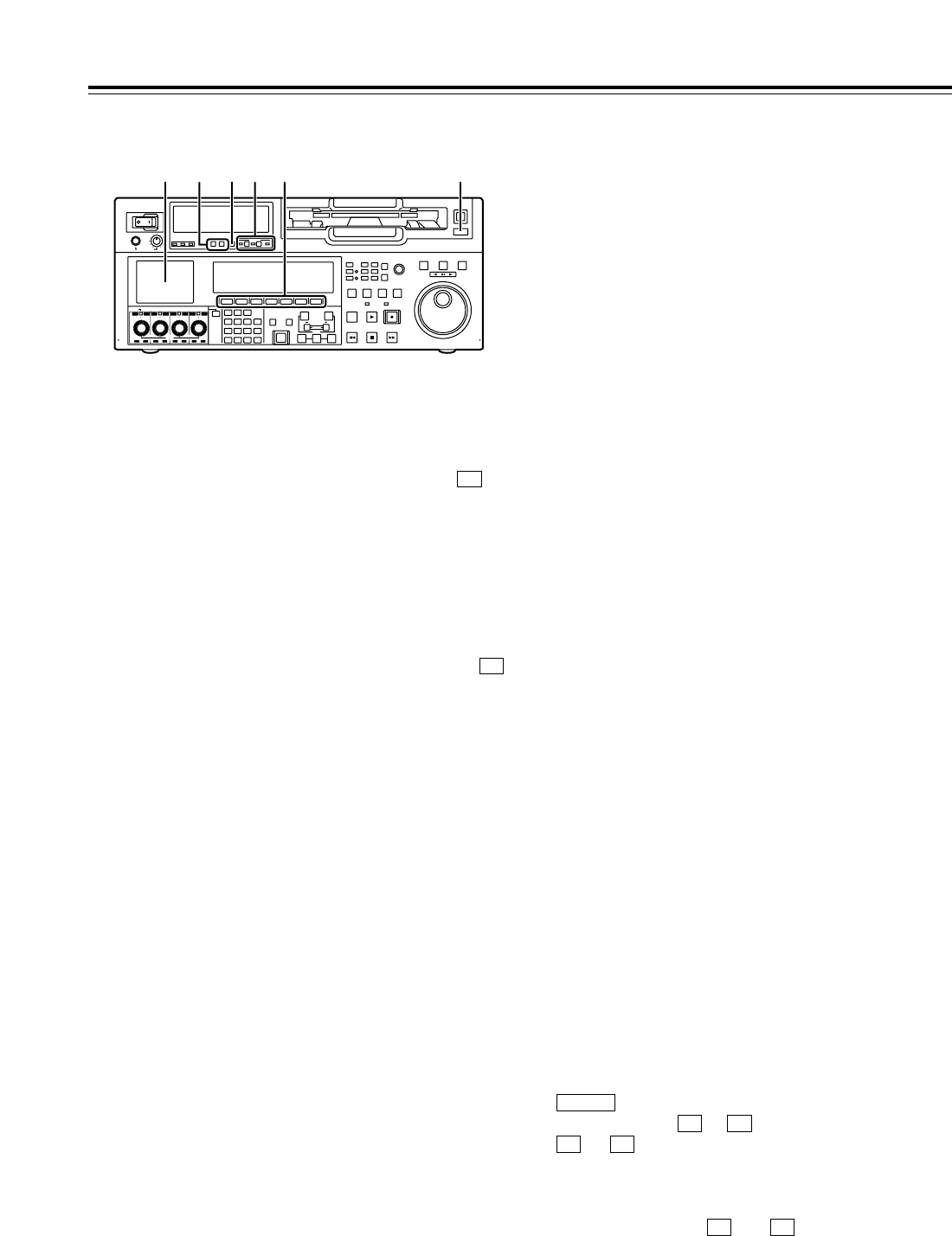
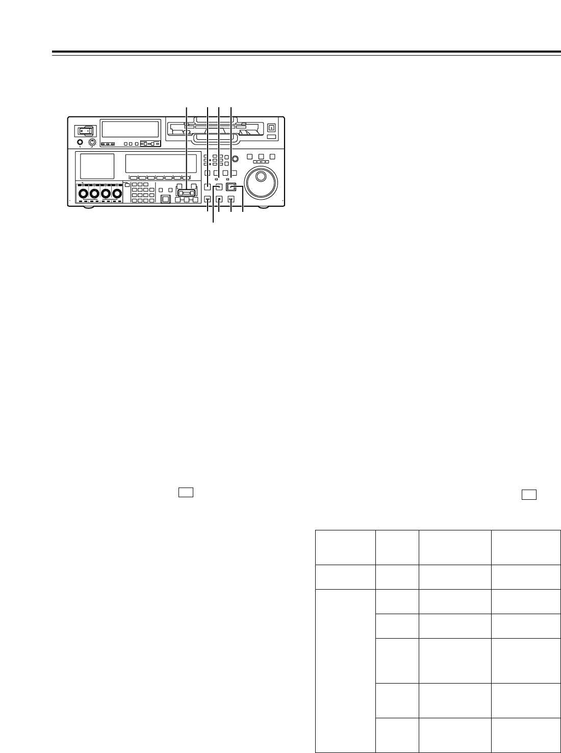
Front panel
8MONITOR SELECT buttons
These buttons are used to select the audio signals
which are to be output to the monitor L and R
connectors and headphones jack.
•When OFF has been selected as the M
MIX setting on the <AUDIO SHIFT2> menu
(factory setting):
Each time the L (or R) button is pressed, the
signal to be output to the monitor L (or R)
connector is changed in the following sequence
and displayed on the audio level meter: CH1 >
CH2 >CH3>CH4 >CH5 >CH6 >CH7 >
CH8 >CUE >CH1, etc.
•
When L, R or L/R has been selected as the
M MIX setting on the <AUDIO SHIFT2> menu:
At this setting, the signals of a multiple number of
channels can be mixed and output.
When the number key corresponding to the
channel whose signals are to be monitored is
pressed while the L (or R) button is held down,
that channel is selected and its signals are
displayed on the audio level meter. (By
performing the same operation, the selected
channel can be de-selected.)
However, a maximum of only two channels from
CH1 to CH4 and a maximum of only two
channels from CH5 to CH8 can be selected.
Example of channels which can be selected:
CH1 iCH3 iCH5 iCH8 “OK
CH1 + CH2 + CH4 “NG
9METER (FULL/FINE) selector button
This button is used to select the scale display for the
audio level meter.
FULL mode: Depending on the setting selected for the
setup menu item No.763 (METER SCALE)*, either the
j¶ to 0 dB (reference level: j20 dB/j18 dB**) or j
to i20 dB (reference level: 0 dB) range is displayed.
FINE mode: Depending on the setting selected for the
setup menu item No.763 (METER SCALE)*, either the
j24 to j15 dB (reference level: j20 dB/j18 dB**) or
j4 to i5 dB (reference level: 0 dB) range is displayed
on a scale with 0.5 dB increments.
* This menu is not displayed for AJ-HD1700E.
** j20 dB is applied for AJ-HD1700P and j18 dB is for AJ-HD1700E.
F6
F6
Parts and Their Functions
:REMOTE buttons and RS-232C display
These buttons are used when this VTR is to be
controlled from an external component using the
REMOTE, RS-232C or parallel connector.
9P: When this button is pressed for 2 or more
seconds, its LED lights, and the 9-pin REMOTE
connector is selected.
50P: When this button is pressed for 2 or more
seconds, its LED lights, and it is possible to control
the VTR from a unit which has been connected using
the 50-pin parallel mode connector.
RS-232C display: This LED lights when communi-
cation has been enabled between the VTR and the
unit which has been connected to the RS-232C
connector.
;AUTO OFF lamp
This lamp lights when a problem has occurred with
the VTR’s operation, and details of the problem
appear on the time code display.
<LCD monitor
This monitor is used to check the tape’s playback
pictures and EE pictures.
When an HD tape is played back, the signals are down-
converted and displayed in the letter-box screen format.
When an SD tape is played back, the signals are
displayed using a 4:3 aspect ratio.
On-screen menus can also be displayed on the monitor.
If the VTR is left in a state where no controls on the front
panel are operated or where the tape is not running, the
monitor display is automatically turned off in order to
protect the monitor. When the next VTR operation is
started, the monitor display comes back on.
<Note>
Although the LCD monitor has been manufactured
using technology with extremely high levels of
precision, some pixels may be missing from parts of
the screen or some pixels may remain lighted.
These missing or lighted pixels will not be recorded.
It should also be borne in mind that this is not
indicative of a malfunction.
=Function buttons
These buttons are used to perform the operations of
the function menus (see page 38 for details) and
setup menus.
: This is used to switch the pages of the current
function menu ( to ).
to : These are used to change the settings of
the setting items enclosed in the frame at the bottom of
the time code display.
To change a setting, keep pressing the corresponding
function button ( to ) until the desired
numerical value appears; alternatively, press the
corresponding function button to highlight the setting of
the setting item, and then turn the ADJUST dial until
the desired numerical value is obtained.
F6F1
F6F1
F6F1
SHIFT
10
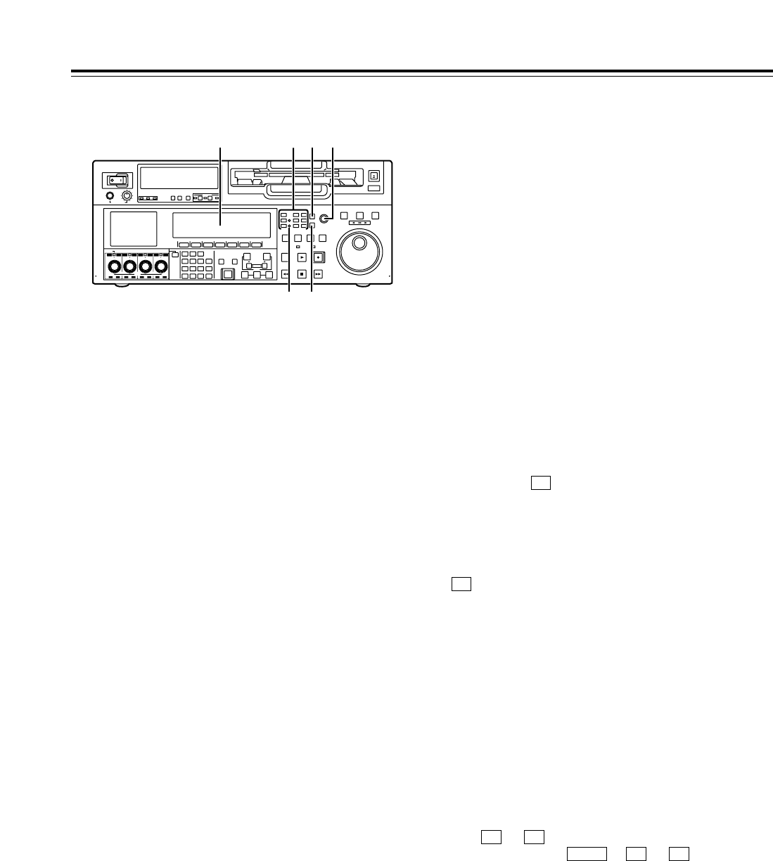
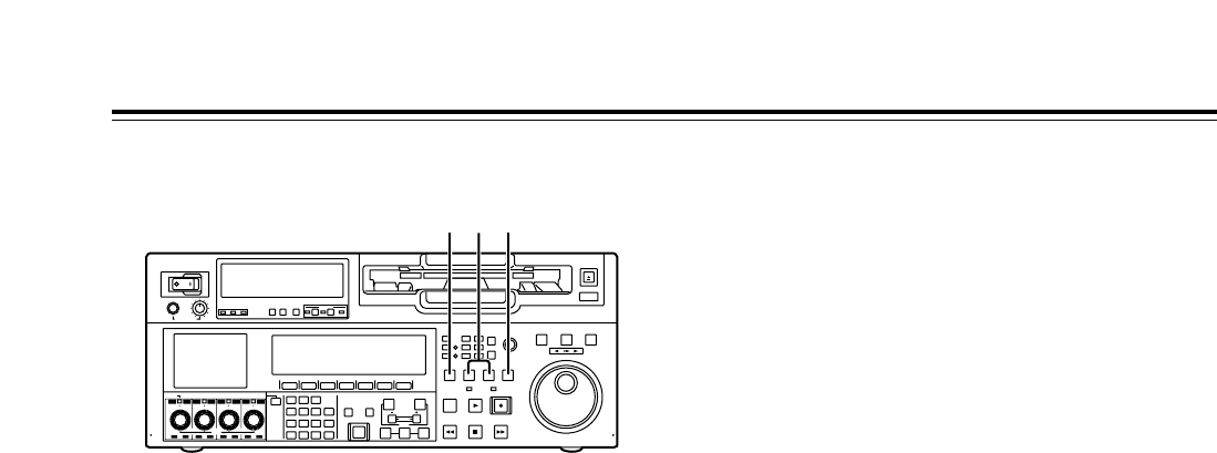
Front panel
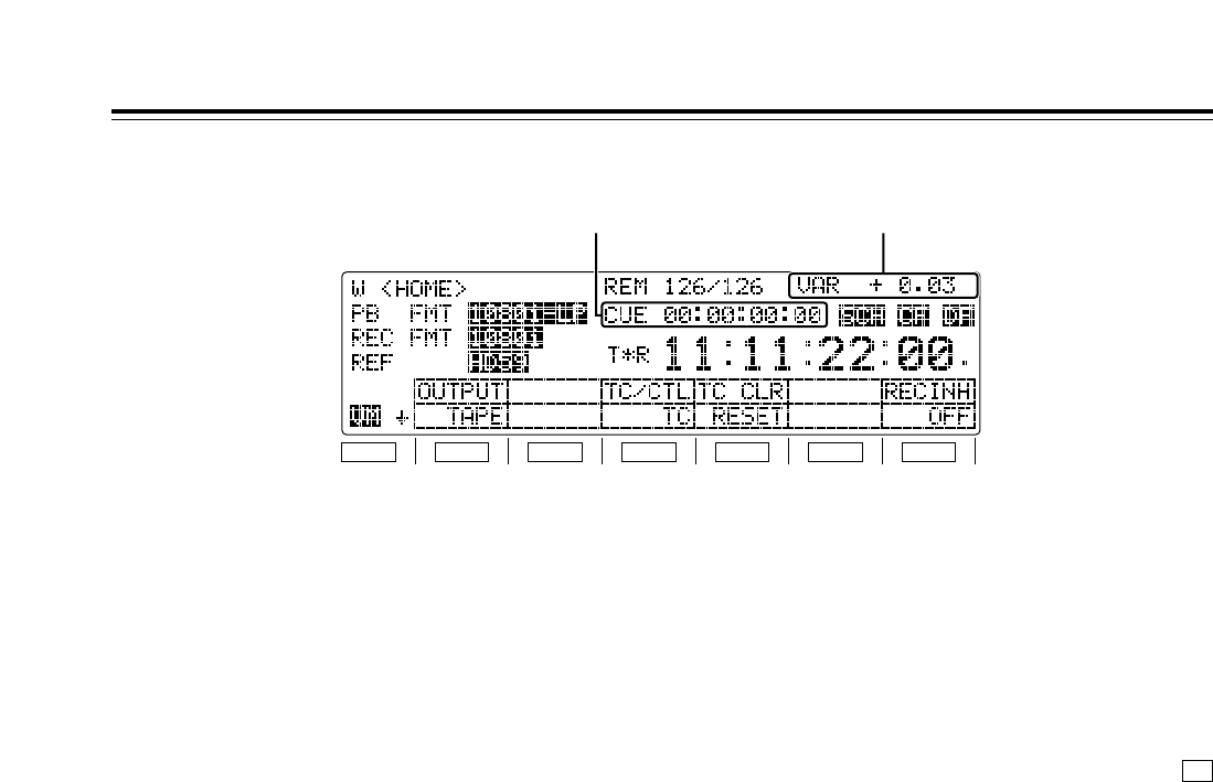
>Time code display
The data, VTR status information, tape format
information or warning information which
corresponds to the direct menu buttons @appear
on this display. (See page 16 for details of the
displays.)
?UNITY lamps
VIDEO UNITY lamp
This lights if the UNITY level applies for all the HD
or SD output levels.
AUDIO UNITY lamp
This lights if the UNITY level applies for the PCM
or CUE AUDIO input or output level. (The lighting
of the lamp complies with the setting selected for
setup menu item No.142 (AUDIO UNITY).)
@Direct menu buttons
These buttons are used to switch directly to the
function menus on the time code display.
HOME: The most basic settings of recording,
playback and time code operations are selected
on this menu.
VIDEO: The basic input and output settings for the
video signals are selected on this menu. The
level of the HD output signals can also be
adjusted on this screen.
AUDIO: The basic input and output settings for the
audio signals are selected on this menu.
PF1: This enables user-defined menu items to be
registered in the function keys.
PF2: This enables user-defined menu items to be
registered in the function keys.
TC: The settings related to the time code are
selected on this menu. Superimposing the time
code on the display can also be set on this
screen.
Parts and Their Functions
POWER
OFF
ON
HEADPHONES
PUSH
LOCK
FULL
CH CONDITION
MONITOR
FULL/FINE
REMOTE
LR
9P 50P
RS-232C
CH12 3 4 5 6 7 8
CUE
XL/L/M
-
cassette
Do not insert S-cassette
without adapter
EJECT
AUDIO CH SELECT
SHIFT
ABC DEF GHI
JKL MNO PQRS
PREVIEW/
REVIEW
PRE-
ROLL
A IN A OUT
HOME RF1 ASSEM
ADJUST
SHTL
REV FWD
VARJOG
STAND BY
RECORDER INPUT CHECK
PLAYER
SERVO
EDIT PLAY REC
REW STOP FF
REC INHIBIT
PUSH-INTER
INSERT
RF2
VIDEO UNITY TC CUE
AUDIO UNITY DIAG MENU
TRIM
SET
IN
OUT
AUTO
EDIT
789
456BS
TUV WXYZ
123
ENT
0CTF
F1 F2 F3 F4 F5 F6
CH
1
CH
5
CH
2
CH
6
CH
3
CH
7
CH
4
CH
8
FULL
REC P8 REC P8 REC P8 REC P8
> A C
? B
@
CUE: This enables up to 60 cue points to be set. In
the PAGE mode, 10 pages with 6 cue points on
each page are provided so that the cue points can
be managed on a page-by-page basis.
DIAG: This enables the warnings and hour meter
displays to be checked. On the SHIFT screen, the
error log files can be checked and deleted.
MENU: On this menu, it is possible to transfer
operation to the screen on which operations
(adjustments and saving data in or loading it from
the internal memory and IC card) relating to the
SYSTEM and SETUP menus are to be performed.
See page 38 and following for further details on
each of the function menus.
AASSEM button
This button is used to perform assemble editing.
When it is pressed, the <ASSEMBLE> menu
appears on the time code display. Setting ASSEM
to ON using enables assemble editing, and the
lamp of the ASSEM button lights.
Even after operation is transferred by another direct
menu, the assemble mode will remain established
while the ASSEM button lamp is lighted.
To release the assemble mode, select OFF as the
ASSEM setting on the <ASSEMBLE> menu.
The ASSEM button lamp now goes off and the
assemble mode is released.
BINSERT button
This button is used to perform insert editing.
When it is pressed, the <INSERT> menu appears
on the time code display, and the function menu for
selecting the signals to be edited is displayed.
To select the signals to be edited, press the
function key, and highlight the display. The
highlighted display indicates that those signals are
selected.
To release the selection, press the same function
key again.
Use to to select the V, A1, A2, A3, A4 and
CUE signals; use + to to select the
A5, A6, A7, A8 and TC signals.
CADJUST dial
This is used for the menu and other operations.
F6F2SHIFT
F6F1
F1
F1
11
Front panel
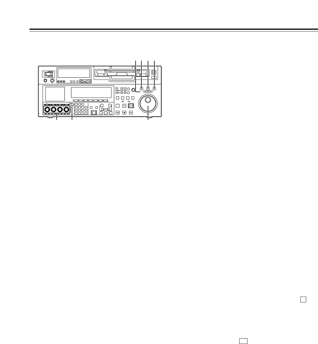
DSHTL button
For shuttle playback, press this button and proceed
with the operation using the search dial G.
When the dial is turned to the desired position, the
tape is played at the speed corresponding to the
angle to which the dial has been turned. A still
picture appears when the dial is set to the center
position.
EJOG button
For jog playback, press this button and proceed
with the operation using the search dial G.
The tape is played at a speed within the speed
range set using setup menu items No.310 (JOG
FWD MAX) and No.311 (JOG REV MAX) in
accordance with the speed at which the dial is
turned.
FVAR button
For VAR playback, press this button and proceed
with the operation using the search dial G.
When the dial is turned all the way in the
counterclockwise direction, the tape speed is set to
j4.9k, when it is set to the center position, it is set
to still picture, and when it is turned all the way in
the clockwise direction, it is set to i4.9k.
The SLOW speed can be selected using setup
menu items No.308 (VAR FWD MAX) and No.309
(VAR REV MAX).
GSearch dial
This dial is used to locate the edit points.
Whether the dial is to be enabled by pressing the
SHTL, JOG or VAR button or whether searches are
to be enabled simply by turning the dial can be
selected using setup menu item No.100 (SEARCH
ENA).
Parts and Their Functions
HREV, STILL and FWD lamps
These lamps light to reflect the way in which the
search dial is operated.
REV: This lights when the dial is turned
counterclockwise, and the tape runs in the REV
direction while the SHTL, JOG or VAR button
lamp is lighted.
STILL: While the JOG button lamp is lighted, this
lights when the dial rotation is stopped, and the
tape also stops running.
In the SHTL or VAR mode, it lights when the dial
is at the still-picture position.
FWD: This lights when the dial is turned clockwise,
and the tape runs in the FWD direction while the
SHTL, JOG or VAR button lamp is lighted.
IAudio input and output level control dials
These are used to adjust the recording or playback
levels of the CH1, CH2, CH3, CH4, CH5, CH6, CH7
and CH8 PCM audio signals.
• Switching between the LOCK or UNLOCK
status for the volume level operations
When a dial is pressed, the LED above the dial
either lights (LOCK) or goes off (UNLOCK).
In the LOCK (lighted) status, only the display
segments corresponding to the current audio
level light, and the audio level remains
unchanged even when the dial is turned.
In the UNLOCK (off) status, the display
segments corresponding to the current audio
level and all the display segments below light,
and the audio level can be changed.
• Switching between UNITY or VAR
UNITY or VAR can be selected when the dial
knob is pressed while holding down the key
among the number keys in the UNLOCK status.
The position of the segment lighted at the center
indicates the UNITY level.
• Switching between REC or PB
The AUTO, REC or PB volume level function can
be selected using of “AUDIO SHIFT2” on the
AUDIO function menu.
With AUTO, the recording controls are
automatically selected during recording or in the
EE or INPUT CHECK status, and the playback
controls are automatically selected during
playback.
• Switching between CH1jCH4 and CH5jCH8
The AUDIO CH SELECT Jis used to switch
between these two sets of channels.
F1
F
POWER
OFF
ON
HEADPHONES
PUSH
LOCK
FULL
CH CONDITION
MONITOR
FULL/FINE
REMOTE
LR
9P 50P
RS-232C
CH12 3 4 5 6 7 8
CUE
XL/L/M
-
cassette
Do not insert S-cassette
without adapter
EJECT
AUDIO CH SELECT
SHIFT
ABC DEF GHI
JKL MNO PQRS
PREVIEW/
REVIEW
PRE-
ROLL
A IN A OUT
HOME RF1 ASSEM
ADJUST
SHTL
REV FWD
VARJOG
STAND BY
RECORDER INPUT CHECK
PLAYER
SERVO
EDIT PLAY REC
REW STOP FF
REC INHIBIT
PUSH-INTER
INSERT
RF2
VIDEO UNITY TC CUE
AUDIO UNITY DIAG MENU
TRIM
SET
IN
OUT
AUTO
EDIT
789
456BS
TUV WXYZ
123
ENT
0CTF
F1 F2 F3 F4 F5 F6
CH
1
CH
5
CH
2
CH
6
CH
3
CH
7
CH
4
CH
8
FULL
REC P8 REC P8 REC P8 REC P8
H D E F
GI J
12
NPREROLL button
This button is used to locate where a transmission
or manual editing starts on the tape.
When it is pressed, the tape travels to the preroll
point and it stops there.
When the cue time has been registered on the
HOME, PF1 or PF2 screen:
The tape is prerolled from the registered cue time
using the preroll time which was set using .
(PREROL) on the <HOME SHIFT> menu.
When the search mode is established on the
CUE screen:
The tape is prerolled from the selected cue point
using the preroll time which was set using
(CU-ROL) on the <CUE SHIFT> menu.
The preroll operation is not performed when the
selected cue point has not been registered or
when the cue point registration mode is
established.
In all other situations:
The tape is prerolled from the registered IN point
(or the current tape position when the IN point has
not been registered) using the preroll time which
was set using [(PREROL) on the <HOME
SHIFT> menu.
If the PREROLL button is pressed when the IN
point has not been registered, the current tape
position is automatically registered as the IN point
(but only when ENA has been selected as the
setup menu item No.305 (AUTO ENTRY) setting).
When the PREROLL button is pressed together
with the IN (A IN) or OUT (A OUT) button, the tape
can be cued up to the registered point concerned.
To cue up the tape for the cue time registered on
the HOME, PF1 or PF2 screen, press the
PREROLL button while holding down the key
among the number keys.
OIN (A IN), SET and OUT (A OUT) buttons
When the IN (A IN) or OUT (A OUT) button is pressed
together with the SET button, the IN (A IN) or OUT (A
OUT) point is registered.The A IN and A OUT buttons
are used to register audio IN and OUT points that
differ from the corresponding video points during
audio split editing.
When an IN (A IN) or OUT (A OUT) point has been
registered, the lamp of the IN (A IN) or OUT (A OUT)
button which has registered that point lights. When
these buttons are pressed after points have been
registered, the IN (A IN) or OUT (A OUT) point value
appears on the counter display.
When the button is pressed while holding down the
IN (A IN) or OUT (A OUT) button, the registration of
the IN (A IN) or OUT (A OUT) point is cleared.
C
F
F1
F5
F1
Front panel
JAudio channel selector button
Use this button to select whether the audio controls
for channels CH1 to CH4 or for channels CH5 to
CH8 are to be controlled.
Each time it is pressed, the channel display LED
above the audio control is selected.
KNumber keys
Use these keys to input the numerical values of the
CUE points, edit points, etc.
By pressing a number keys from to while the
key is held down, alphabet letters from A to F
which are used for the user’s bit or letters from A to
Z which are used to compose filenames can be
input.
Since a multiple number of letters are allocated to
each number key, keep tapping the number key
until the desired letter is selected. To change the
input position, use the ADJUST dial, and then
proceed with the input.
LPREVIEW/REVIEW button
PREVIEW: When the button is pressed after an edit
point has been registered, the tape travels and the
editing can be previewed without actually
performing the editing.
If the button is pressed when the IN point has not
been registered, the point where it was pressed is
registered as the IN point, and preview is
executed using this IN point.
REVIEW: When the button is pressed after a
section has been edited, the just edited section is
played back, and it can be reviewed on the
recorder’s monitor.
MAUTO EDIT button
When this button is pressed after the edit points
have been registered, automatic editing is initiated.
If the button is pressed when the IN point has not
been registered, automatic editing is initiated with
the point where the button was pressed serving as
the IN point.
F
91
Parts and Their Functions
POWER
OFF
ON
HEADPHONES
PUSH
LOCK
FULL
CH CONDITION
MONITOR
FULL/FINE
REMOTE
LR
9P 50P
RS-232C
CH12 3 4 5 6 7 8
CUE
XL/L/M
-
cassette
Do not insert S-cassette
without adapter
EJECT
AUDIO CH SELECT
SHIFT
ABC DEF GHI
JKL MNO PQRS
PREVIEW/
REVIEW
PRE-
ROLL
A IN A OUT
HOME RF1 ASSEM
ADJUST
SHTL
REV FWD
VARJOG
STAND BY
RECORDER INPUT CHECK
PLAYER
SERVO
EDIT PLAY REC
REW STOP FF
REC INHIBIT
PUSH-INTER
INSERT
RF2
VIDEO UNITY TC CUE
AUDIO UNITY DIAG MENU
TRIM
SET
IN
OUT
AUTO
EDIT
789
456BS
TUV WXYZ
123
ENT
0CTF
F1 F2 F3 F4 F5 F6
CH
1
CH
5
CH
2
CH
6
CH
3
CH
7
CH
4
CH
8
FULL
REC P8 REC P8 REC P8 REC P8
NL
J MK O
13
Front panel
PTRIM buttons
These buttons are used to make fine adjustments to the
IN or OUT point.
By pressing the ior jbutton while the IN button or OUT
button is held down, the registered edit point can be
adjusted in 1-frame increments. When the ibutton is
pressed, the point is moved ahead by one frame;
conversely, when the jbutton is pressed, it is moved
back by one frame.
The playback phase can be adjusted by pressing the i
or jbutton while holding down the PLAY button.
QREW button
When this button is pressed, the tape is rewound.
The rewinding speed can be selected using setup menu
item No.102 (FF.REW MAX).
RSTOP button
When this button is pressed, the tape stops traveling, and
if TAPE is selected as the OUTPUT setting on the
<HOME> menu, still pictures can be monitored.
Even in the stop mode, the drum continues to rotate, and
the tape remains tightly wound around the drum.
Therefore, when the VTR is left in the stop mode beyond
a specific period of time, it is automatically set to the
standby OFF mode in order to protect the tape. The VTR
is set to the stop mode immediately after the cassette has
been installed.
SFF button
When this button is pressed, the tape is fast forwarded.
The fast forwarding speed can be selected using setup
menu item No.102 (FF.REW MAX).
TEDIT button
This button is pressed together with the PLAY button
during playback to initiate manual editing.
When the button is pressed in the stop mode, the input
signals in the mode selected by the <ASSEMBLE> menu
or <INSERT> menu can be monitored in the E-E mode.
F1
Parts and Their Functions
When the STOP button is pressed, the original picture
and sound are restored.
During playback, search, fast forwarding or rewinding, the
input signals in the mode selected by the <ASSEMBLE>
menu or <INSERT> menu can be monitored in the E-E
mode while the button is held down.
<Note>
No guarantees are made for the sound played back in the
search mode.
U
PLAY button
Press this button to start playback.
When this button is pressed together with the REC
button, recording starts; when this button is pressed
together with the EDIT button during playback, manual
editing starts.
However, manual editing will not be initiated if the servo
is not locked. When only the PLAY button is pressed
during manual editing, editing is exited, and the playback
mode is established.
V
REC button
When this button is pressed together with the PLAY
button, recording starts.
W
SERVO lamp
This lamp lights when the drum servo or capstan servo
locks.
X
REC INHIBIT lamp
This lights or goes off in accordance with the status of the
accidental erasure prevention tab on the cassette tape
and the setting which has been selected for REC
INH on the <HOME> menu. Recording onto the tape is
inhibited while the lamp is lighted.
F6
POWER
OFF
ON
HEADPHONES
PUSH
LOCK
FULL
CH CONDITION
MONITOR
FULL/FINE
REMOTE
LR
9P 50P
RS-232C
CH12 3 4 5 6 7 8
CUE
XL/L/M
-
cassette
Do not insert S-cassette
without adapter
EJECT
AUDIO CH SELECT
SHIFT
ABC DEF GHI
JKL MNO PQRS
PREVIEW/
REVIEW
PRE-
ROLL
A IN A OUT
HOME RF1 ASSEM
ADJUST
SHTL
REV FWD
VARJOG
STAND BY
RECORDER INPUT CHECK
PLAYER
SERVO
EDIT PLAY REC
REW STOP FF
REC INHIBIT
PUSH-INTER
INSERT
RF2
VIDEO UNITY TC CUE
AUDIO UNITY DIAG MENU
TRIM
SET
IN
OUT
AUTO
EDIT
789
456BS
TUV WXYZ
123
ENT
0CTF
F1 F2 F3 F4 F5 F6
CH
1
CH
5
CH
2
CH
6
CH
3
CH
7
CH
4
CH
8
FULL
REC P8 REC P8 REC P8 REC P8
T XW
U
R S V
Q
P
Cassette tape’s
accidental erasure
prevention tab status
REC INH
menu setting
REC INHIBIT
lamp status Description of
operation
Recording
disabled __ Lighted*
(or blinks slowly).
All recording operations
are inhibited.
Recording
enabled
OFF Off
All recording operations
are permitted.
ALL Lighted
All recording operations
are inhibited.
PRE Blinks rapidly
Recording operations
involving the overwriting
of existing material are
inhibited.
NORM Blinks rapidly
Normal recording
operations are inhibited.
Editing is possible.
V/CTL Blinks rapidly
Recording of video
signals and CTL signals
are inhibited.
* Whether the REC INHIBIT lamp is to light or blink is selected by
the No.114 REC INH LAMP setup menu item setting.
14
Front panel
YSTANDBY button
The same tape tension is applied as in the regular
stop mode. While the head drum is rotating, the
button’s lamp lights to indicate that the standby ON
mode is now established.
If the button is pressed in the stop mode, the
standby OFF mode is established followed by the
half loading mode. At this time, its lamp goes off.
When the VTR is left in the stop mode beyond a
specific period of time, it is automatically set to the
standby OFF mode in order to protect the tape.
In the standby OFF mode, if this button or the
STOP button is pressed, the VTR is set to the
standby ON mode. If a button other than the
STOP button is pressed, the VTR is set to the
mode that corresponds to the button pressed.
The time taken by the VTR to transfer to the
standby OFF mode can be selected using a setup
menu item.
Parts and Their Functions
ZPLAYER and RECORDER buttons
These buttons are operated if the VTR is to be used
as a recorder to conduct editing operations with a
VTR equipped with an RS-422A serial interface
remote control connector (9 pins). Neither button
works when the VTR is used on its own.
PLAYER: When this button is pressed, its lamp
lights to indicate that the player connected to the
VTR can be operated by remote control. The
VTR’s editing and tape transport system buttons
can now be used to control the player.
RECORDER: When this button is pressed, its lamp
lights to indicate that the editing and tape
transport system buttons can now be used to
operate the recorder (this VTR).
• When the PLAYER button or RECORDER button
is pressed while ENA has been selected as the
setup menu item No.200 (PARA RUN) setting,
the lamps of both buttons light to indicate that the
VTR now serves as the master unit for parallel
run operations. However, when this setting is
used, it is no longer possible to perform external
control from the REMOTE connector (9 pins).
[INPUT CHECK button
Only while this button is held down are the input
signals from the monitor output connector output to
enable the input video and audio signals to be
monitored.
The time code generator can be checked on the
time code display.
Select LATCH as the setup menu item No.517
(TCG OUT) setting in order to continue displaying
the time code generator value even after the INPUT
CHECK button has been released.
<Note>
The INPUT CHECK function does not work for the
CUE signal and SDTI signals. Input signals can be
monitored in the E-E mode.
POWER
OFF
ON
HEADPHONES
PUSH
LOCK
FULL
CH CONDITION
MONITOR
FULL/FINE
REMOTE
LR
9P 50P
RS-232C
CH12 3 4 5 6 7 8
CUE
XL/L/M
-
cassette
Do not insert S-cassette
without adapter
EJECT
AUDIO CH SELECT
SHIFT
ABC DEF GHI
JKL MNO PQRS
PREVIEW/
REVIEW
PRE-
ROLL
A IN A OUT
HOME RF1 ASSEM
ADJUST
SHTL
REV FWD
VARJOG
STAND BY
RECORDER INPUT CHECK
PLAYER
SERVO
EDIT PLAY REC
REW STOP FF
REC INHIBIT
PUSH-INTER
INSERT
RF2
VIDEO UNITY TC CUE
AUDIO UNITY DIAG MENU
TRIM
SET
IN
OUT
AUTO
EDIT
789
456BS
TUV WXYZ
123
ENT
0CTF
F1 F2 F3 F4 F5 F6
CH
1
CH
5
CH
2
CH
6
CH
3
CH
7
CH
4
CH
8
FULL
REC P8 REC P8 REC P8 REC P8
Y [Z
15
Front panel
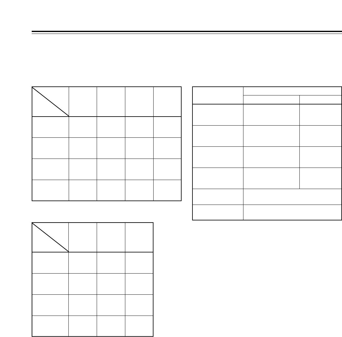
INPUT CHECK output specifications
VIDEO (59/60 Hz mode)
Parts and Their Functions
AUDIO
Output system
MONITOR L
HD SDI (MONITOR)
(embedded audio)
SD SDI (MONITOR)
(embedded audio)
MONITOR (L, R) selection
CH1 to CH8
Audio input which has been
set by the channels selected
as L channels*2
Same as main
system*1
Same as main
system*1
Same as main system*1*3
Same as main system*1*3
CUE
MONITOR R
HEAD PHONE L
Audio input which has been
set by the channels selected
as R channels*2
Audio input which has been
set by the channels selected
as L channels*2
Same as main
system*1
Same as main
system*1
HEAD PHONE R Audio input which has been
set by the channels selected
as R channels*2
<Notes>
• The AJ-UC1700G (optional accessory) is required to
select the SD SDI input signals.
• The AJ-YAC150P (optional accessory) is required to
select the SDTI input signals.
• When the INT SG input signal is selected, the signals are
selected by menu item No.601.
• When the 23/24 Hz mode or 25 Hz (HD or SD) mode is
selected, the INPUT CHECK operation is not performed.
* When the SDTI input is selected, the INPUT CHECK operation is
not performed.
*1: The INPUT CHECK operation is not performed. The signals
corresponding to the VTR operation mode are output.
*2: This is set using setup menu items No.713 to 724. However,
the INPUT CHECK operation is not performed when video
input SDTI is selected.
*3: Noise may occur if the video input and OUTREF signals are
not synchronized.
Output system
HD SDI
(MONITOR)
(59.94Hz/60Hz)
Input selection
(MENU 600)
INT SG
(59.94Hz/
60Hz)
INT SG
(selected
signal)
HD SDI
(input signal)
MUTE
(BLACK)
Same as
main system*
HD SDI
(59.94Hz/
60Hz)
SD SDI
(59.94Hz) SDTI
(59.94 Hz)
SD SDI
(MONITOR)
(59.94Hz)
MUTE
(BLACK)
MUTE
(BLACK)
SD SDI
(input signal)
Same as
main system*
LCD
(MONITOR)
(59.94Hz/60Hz)
INT SG
(selected
signal)
HD SDI
(input signal)
SD SDI
(input signal)
Same as
main system*
VIDEO OUT3
(59.94Hz)
Same as
main system*
Same as
main system*
Same as
main system*
Same as
main system*
VIDEO (50 Hz mode)
Output system
HD SDI
(MONITOR)
(50Hz)
Input selection
(MENU 600)
INT SG
(50Hz)
INT SG
(selected
signal)
HD SDI
(input signal)
MUTE
(BLACK)
HD SDI
(50Hz) SD SDI
(50Hz)
SD SDI
(MONITOR)
(50Hz)
MUTE
(BLACK)
MUTE
(BLACK)
SD SDI
(input signal)
LCD
(MONITOR)
(50Hz)
INT SG
(selected
signal)
HD SDI
(input signal)
SD SDI
(input signal)
VIDEO OUT3
(50Hz)
Same as
main system*
Same as
main system*
Same as
main system*
16
1Cue time display
The currently registered cue time appears here.
(For details of the cue time operations, refer to “Cue
time registration, preroll and cue-up” on page 112.)
Cue time operations can be performed on the
HOME, PF1 and PF2 screens only.
2Operation mode (speed) display
The current operation mode (including the speed
display) appears here.
EJECT:
Eject mode
STANDBY OFF:
Standby OFF mode
T.RELEASE:
Tension release mode
STOP:
Stop mode
PREROLL:
Preroll mode
PLAY:
Playback mode
PLAYi:
Special playback (playback phase adjustment)
mode (in FWD direction)
PLAYj:
Special playback (playback phase adjustment)
mode (in REV direction)
REC:
Recording mode
JOG (REV/STILL/FWD):
Jog mode
VAR (speeds from j4.9kto i4.9k):
Variable mode
SHTL (speeds from j32.kto i32.0k):
Shuttle mode
FF:
Fast forwarding mode
REW:
Rewinding mode
EDIT:
Editing mode
AUTO EDIT:
Automatic editing mode
PREVIEW:
Preview mode
REVIEW:
Review mode
• When “ON” has been selected as the [F]
(VARMEM) setting on the <HOME SHIFT>
menu:
DSPD (speeds from j1.0 to i2.0)
With the initial speed setting of the variable
memory
DSMP (speeds from j1.0 to i2.0)
In the playback speed memory mode of the
variable memory
DPLY (speeds from j1.0 to i2.0)
In the variable memory playback mode
DPRV (speeds from j1.0 to i2.0)
In the variable memory editing preview mode
DEDT (speeds from j1.0 to i2.0)
In the variable memory editing execution mode
Parts and Their Functions
Time code display
F1
SHIFT
F2 F3 F4 F5 F6
21
F6
17
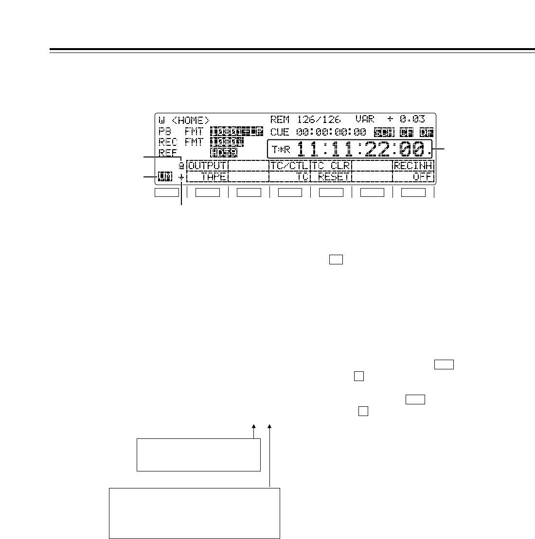
3Time counter display
CTL: CTL counter data
TCG: Time code data of time code generator
UBG: User’s bit data of time code generator
tcg: When the time code data of the time
code generator is preset
ubg: When the user’s bit data of the time
code generator is preset
TCR/T¢R: Time code data of the time code reader
UBR/U¢R: User’s bit data of the time code reader
If the time code data or user’s bit data could not be
read properly, “T¢R” or “U¢R” appears on the
display and, if the CTL signal is present, the time
code data is supplemented by this signal.
4Variable memory mode indicator
This is displayed when “ON” has been selected as
the (VARMEM) setting on the <HOME SHIFT>
menu.
While VM is lighted, variable memory operations
can be performed at any time. (For details, refer to
the “Variable memory function” on page 36.)
5Back page menu indicator
6Function button operation inhibited indicator
This is displayed when the button is pressed
while the button is held down. When it appears,
the operation of the function buttons can be
inhibited. When the button is pressed again
while the button is held down, the display is
cleared, and it becomes possible to operate the
function buttons.
F
BS
F
BS
F6
Parts and Their Functions
Time code display
F1
SHIFT
F2 F3 F4 F5 F6
6
4
5
3
TCR 00 : 00 : 00 : 00.
Field marks
“ ”: 1st field
“ . ”: 2nd field
(These marks are not displayed at any
speed above w0.3k.)
Drop frame marks:
“ : ”: Non-drop frame
“ . ”: Drop frame
(59/60 Hz mode only)
18
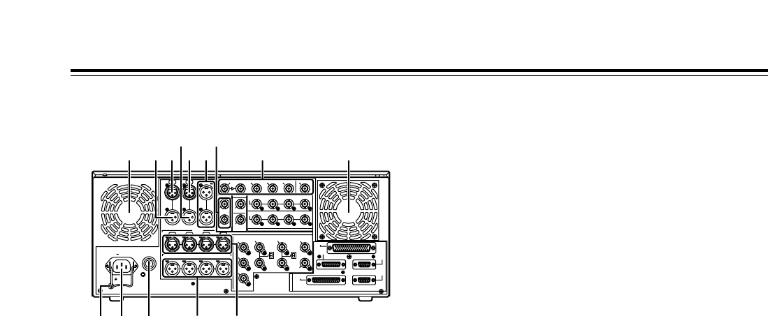
Rear panel
1AC IN socket
Using the power cord supplied, connect one end to
this socket and the other end to the power outlet.
2SIGNAL GND terminal
This is connected to the signal ground terminal on
the component connected to this VTR in order to
minimize noise. It is not a safety ground.
3Fuse holder
A fuse is inserted here.
4Fan
The fan is used to cool down the VTR.
If the fan has been stopped due to some kind of
problem, “W” appears on the time code display and
a beeping sound is heard.
If the VTR is made to continue operating in the
warning status, the temperature inside the deck
rises, and when it exceeds the safety temperature,
all the VTR’s operations will be shut down.
5TIME CODE IN connector
This connector is used to record an external time
code onto the tape.
6TIME CODE OUT connector
During playback, the playback time code is output
through this connector. During recording, the time
code generated by the internal time code generator
is output.
7CUE IN connector
The analog signals to be recorded on the CUE
tracks are input through this connector.
Audio signals from a microphone can also be
recorded by selecting the j60 dB input mode for
setup menu item No.704 (CUE IN LV).
Parts and Their Functions
8CUE OUT connector
The analog signals recorded on the CUE tracks are
output through this connector.
9MONITOR OUT connectors
The CH1, CH2, CH3, CH4, CH5, CH6, CH7 and
CH8 PCM audio signals or CUE signals are output
through these connectors.
:ANALOG AUDIO IN connectors
These are the analog audio input connectors (for
CH1, CH2, CH3 and CH4).
;ANALOG AUDIO OUT connectors
The analog audio signals (CH1, CH2, CH3 and
CH4) are output through these connectors.
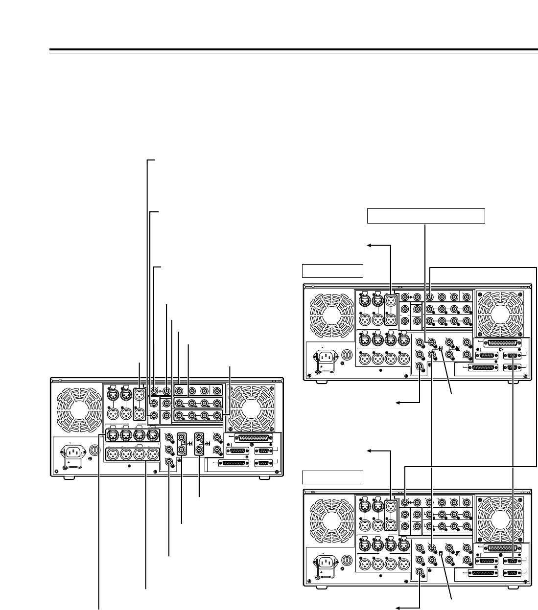
<
HD SERIAL DIGITAL COMPONENT AUDIO/VIDEO
IN/OUT connector/ACTIVE THRU
The HD digital component audio and video signals
complying with the SMPTE 292M and 299M
standards are input and output through this
connector.
Signals with the time code, menu or other
superimposed information are output from the HD
SDI MONITOR.
For INPUT CHECK, refer to the INPUT CHECK
output table on page 15.
=SDTI IN and OUT connectors (SDTI, optional
accessory)*1, SD SDI IN/ACTIVE THRU (SD up-
converter, optional accessory)*2
*1: These connectors handle compressed data
input and output signals complying with the
SMPTE 305M and 321M standards.
*2: These input connectors enable SD SDI signals
complying with the SMPTE 259M-C standard to
be up-converted to HD signals and recorded.
<Notes>
• The optional AJ-UC1700G SD serial digital input
board and optional AJ-YAC150P SDTI input
board cannot be installed at the same time.
Install one or the other.
• SDTI does not function when the 25 Hz (HD or
SD) or 50 Hz mode has been selected as the
system menu item No.25 (SYSTEM FREQ)
setting.
PUSHPUSH
PUSH PUSH PUSH PUSH
SIGN
AC IN
TC
IN IN L
OUT
CH 1
AUDIO IN
CH 2 CH 3 CH 4
VIDEO OUT
(WFM)
ON
OFF
75≠
ON
OFF
75≠
(SUPER)
1
2
3
SD REF IN
CH1·2
AUDIO
OUT
CH3·4 CH5·6 CH7·8
HD REF IN HD REF OUT
SD
REF OUT
RS-232C
ENCODER
REMOTE
REMOTE
IN/OUT
REMOTE
OUT
PARALLEL
CH 1 CH 2 CH 3 CH 4
OUT R
CUE MON
PUSH PUSH PUSH
L
GD
CH1·2
AUDIO
IN
CH3·4 CH5·6 CH7·8
ACTIVE
THROUGH
(SUPER)
ANALOG
DIGITAL AUDIO
SD SDI
(OPTION)
HD SDI
SDTI
R
E
M
O
T
E
IN
OUT
OUT 1IN OUT 2 OUT 3
MONITOR (SUPER)
MONITOR
AUDIO OUT
4 45
8
76
12 3
9 <
:;
=
19
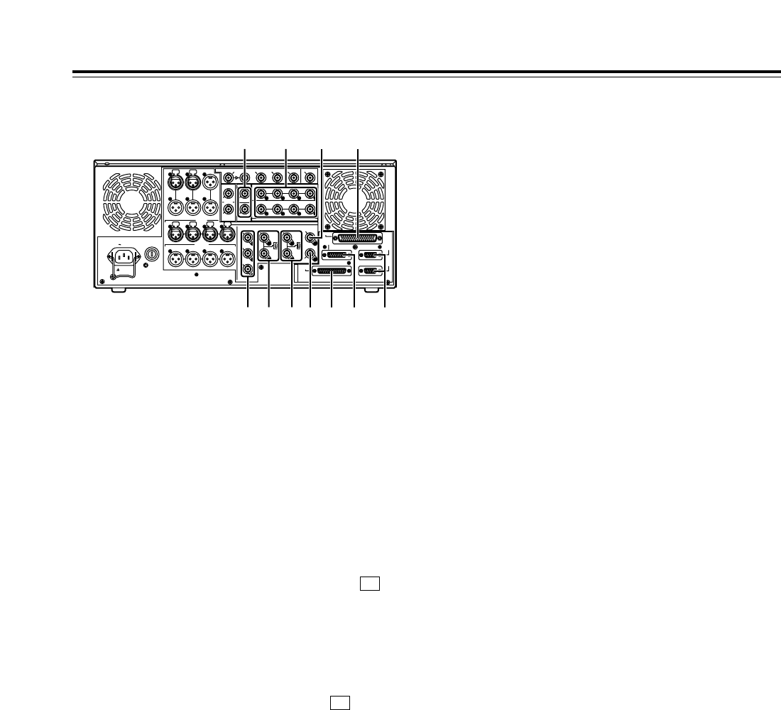
Rear panel
>SD SERIAL DIGITAL COMPONENT AUDIO and
VIDEO OUT connectors
The digital component audio and video signals
complying with the SMPTE 259M-C, 272M-A or
294M standard are output from these connectors.
They are output during DVCPRO25M, 50M, DV or
DVCAM interchangeable playback or when signals
are down-converted and output. Signals containing
TC, menu or other superimposed information can
be output from the SD SDI MONITOR.
Using setup menu item No.606 (SD MONI O SEL),
it is also possible to make the SD SDI MONITOR
output the same output as SD SDI OUT1 (no
information superimposed).
When “SD SDI” has been selected as the (VID
IN) setting on the <VIDEO> menu and “THRU” has
been selected as the No.107 (EE MODE SEL)
setting, no information is superimposed onto the SD
SDI MONITOR output signals in the EE mode, and
the same output as SD SDI OUT1 is delivered.
• The AJ-UC1700G optional board is required in
order to select “SD SDI” as the (VID IN)
setting on the <VIDEO> menu.
• For INPUT CHECK, refer to the INPUT CHECK
output table on page 15. Note that the signals
are muted during line conversion.
<Note>
In the 23/24 Hz mode, the system phase of the SD
SDI output and analog composite video output is
subject to change when the tape has been set to
travel at the normal speed (1k) so that the HD SDI
output and phase will be aligned.
?ANALOG COMPOSITE VIDEO OUT connectors
The analog composite video signals are output through
these connectors. They are output during DVCPRO25M,
50M, DV or DVCAM interchangeable playback or when
signals are down-converted and output.
Video signals containing superimposed information can
be output through the VIDEO OUT 3 connector. Whether
the superimposing is to be set ON or OFF is selected
using the setup menu item No.005 (SUPER).
The waveform monitor (WFM) signal can be output from
the VIDEO OUT 2 connector.
F1
F1
Parts and Their Functions
The signals which can be switched using the menu items
are the TC, CTL, video, RF L/R and ENV L/R signals.
There is no INPUT CHECK function. The signals are
muted during line conversion.
@SD REF IN connectors and 75-ohm termination
switches
These are the SD reference video signal input
connectors. Input composite signal with color burst.
For termination, set the termination switch to ON.
AHD REF IN connectors and 75-ohm termination
switches
These are the HD reference video signal input
connectors. Input tri-level sync signals with both positive
and negative polarities.
For termination, set the termination switch to ON.
BHD REF OUT connector
This is the HD reference video signal output connector for
external synchronization. Tri-level sync signals with both
positive and negative polarities are output.
The output based on SYS FORMAT of menu item No.020
is delivered from the connector.
CSD REF OUT connector
The composite signal used for external synchronization
(black burst signal) is output from this connector.
DDIGITAL AUDIO IN and OUT connectors
These are the input and output connectors of the digital
audio signals that comply with the AES/EBU standards.
E
Remote control connectors
These connectors make it possible to use two of these
VTRs or to connect this VTR to an external controller so
that this VTR can be operated from an external
component.
Two remote control connectors are provided: one for
IN/OUT uses and the other for OUT uses only.
IN/OUT:For connection with an external controller
For connection during deck-to-deck operations
OUT: For connection during parallel run operations
For loop-through uses
F
ENCODER REMOTE connector
An external encoder remote controller is connected to
this connector when the video output signal settings are
to be adjusted from an external component.
G
RS-232C connector
H
PARALLEL REMOTE connector
This is used when the VTR is to be operated from an
external component.
SIGN
AC IN
TC
IN IN L
OUT
CH 1
AUDIO IN
CH 2 CH 3 CH 4
VIDEO OUT
(WFM)
ON
OFF
75≠
ON
OFF
75≠
(SUPER)
1
2
3
SD REF IN
CH1·2
AUDIO
OUT
CH3·4 CH5·6 CH7·8
HD REF IN HD REF OUT
SD
REF OUT
RS-232C
ENCODER
REMOTE
REMOTE
IN/OUT
REMOTE
OUT
PARALLEL
CH 1 CH 2 CH 3 CH 4
OUT R
CUE MON
L
GD
CH1·2
AUDIO
IN
CH3·4 CH5·6 CH7·8
ACTIVE
THROUGH
(SUPER)
ANALOG
DIGITAL AUDIO
SD SDI
(OPTION)
HD SDI
SDTI
R
E
M
O
T
E
IN
OUT
OUT 1IN OUT 2 OUT 3
MONITOR (SUPER)
MONITOR
AUDIO OUT
B> D H
EF? @ A C G
PUSH PUSH
PUSH PUSH PUSH PUSH
20
PUSH PUSH PUSH PUSH
SIGN
AC IN
TC
IN IN L
OUT
CH 1
AUDIO IN
CH 2 CH 3 CH 4
VIDEO OUT
(WFM)
ON
OFF
75≠
ON
OFF
75≠
(SUPER)
1
2
3
SD REF IN
CH1·2
AUDIO
OUT
CH3·4 CH5·6 CH7·8
HD REF IN HD REF OUT
SD
REF OUT
RS-232C
ENCODER
REMOTE
REMOTE
IN/OUT
REMOTE
OUT
PARALLEL
CH 1 CH 2 CH 3 CH 4
OUT R
CUE MON
PUSH
L
GD
CH1·2
AUDIO
IN
CH3·4 CH5·6 CH7·8
ACTIVE
THROUGH
(SUPER)
ANALOG
DIGITAL AUDIO
SD SDI
(OPTION)
HD SDI
SDTI
R
E
M
O
T
E
IN
OUT
OUT 1IN OUT 2 OUT 3
MONITOR (SUPER)
MONITOR
AUDIO OUT
PUSH PUSH
HD SDI input (audio, video)
SDTI input (when SDTI, an optional
accessory, has been installed)
SD SDI input (when SD up-converter,
an optional accessory, has been
installed)
SDTI output (when SDTI, an optional
accessory, has been installed)
SD SDI input ACTIVE THRU (when SD
up-converter, an optional accessory, has
been installed)
Audio monitor outputs
Analog audio inputs
Analog audio outputs
HD SDI output
(ACTIVE THRU)
SD SDI outputs
Digital audio inputs
Digital audio outputs
HD reference inputs
(loop-through output)
SD reference inputs
(loop-through output)
Video monitor output
(3 composite output lines)
Example of connections performed
for one VTR
Player side:
Set the REMOTE LED :on the front panel to the off
status (LOCAL mode).
Connections
HD SDI outputs
Example of connections performed
for two VTRs (deck-to-deck)
Source side:
Press the “9P” REMOTE button on the front panel
for 2 or more seconds to set the VTR to the
REMOTE status. (The 9P LED lights.)
Recorder side:
Set the REMOTE LED :on the front panel to the
off status (LOCAL mode).
SIGN
AC IN
TC
IN L
OUT
CH 1
AUDIO IN
CH 2 CH 3 CH 4
VIDEO OUT
(WFM)
ON
OFF
75≠
ON
OFF
75≠
(SUPER)
1
2
3
SD REF IN
CH1·2
AUDIO
OUT
CH3·4 CH5·6 CH7·8
HD REF IN HD REF OUT
SD
REF OUT
RS-232C
ENCODER
REMOTE
REMOTE
IN/OUT
REMOTE
OUT
PARALLEL
CH 1 CH 2 CH 3 CH 4
R
MON
L
GD
CH1·2
AUDIO
IN
CH3·4 CH5·6 CH7·8
ACTIVE
THROUGH
(SUPER)
ANALOG
DIGITAL AUDIO
SD SDI
(OPTION)
HD SDI
SDTI
R
E
M
O
T
E
IN
OUT
OUT 1IN OUT 2 OUT 3
MONITOR (SUPER)
MONITOR
AUDIO OUT
PUSH PUSH PUSH PUSH
SIGN
AC IN
TC
IN IN L
OUT
CH 1
AUDIO IN
CH 2 CH 3 CH 4
VIDEO OUT
(WFM)
ON
OFF
75≠
ON
OFF
75≠
(SUPER)
1
2
3
SD REF IN
CH1·2
AUDIO
OUT
CH3·4 CH5·6 CH7·8
HD REF IN HD REF OUT
SD
REF OUT
RS-232C
ENCODER
REMOTE
REMOTE
IN/OUT
REMOTE
OUT
PARALLEL
CH 1 CH 2 CH 3 CH 4
OUT R
CUE MON
L
GD
CH1·2
AUDIO
IN
CH3·4 CH5·6 CH7·8
ACTIVE
THROUGH
(SUPER)
ANALOG
DIGITAL AUDIO
SD SDI
(OPTION)
HD SDI
SDTI
R
E
M
O
T
E
IN
OUT
OUT 1IN OUT 2 OUT 3
MONITOR (SUPER)
MONITOR
AUDIO OUT
PUSH PUSH
PUSH PUSH PUSH PUSH
PUSH PUSH
SD reference signal generator
Source side
Recorder side
To audio monitor
cmponent
To video monitor
component
To audio monitor
component
To video monitor
component
HD SDI signal
Remote
signal (9P)
OFF
ON
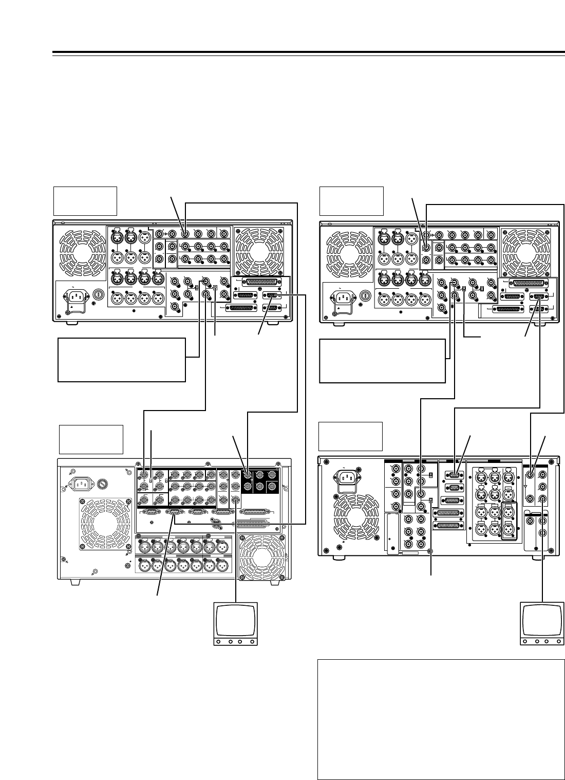
21
Note concerning tapes played back by this VTR
• Use tapes which have been shot by a variable frame rate
camera.
• Do not use tapes which are copies of shot tapes or edited tapes.
Doing so will cause the tape management information to be lost,
and normal conversion and playback may not be possible as a
result.
• To convert a tape, which was recorded at a frame rate other than
24fps (25fps), to 1080/24psf (1080/25psf), use a frame rate
converter (AJ-FRC27) which is available as an optional
accessory.
Connections
When this VTR plays back a tape which was recorded at a frame rate of 24
fps (25 fps) using a variable frame rate camera, the signals on the tape can
be output after converting them to 1080/24psf (1080/25psf) to enable direct
editing together with the AJ-HD3700 series.
Shown in the figure below is an example of the deck-to-deck connections.
Input the 48 Hz (or 50 Hz) reference signal to the HD REF input connector
as the REF input.
When this VTR plays back a tape which was recorded at a frame rate of 25
fps using a variable frame rate camera, the signals on the tape can be
output after converting them to 576/50i to enable direct editing together
with the SD VTRs.
Shown in the figure below is an example of the deck-to-deck connections.
Input the 50 Hz reference signal to the SD REF input connector as the REF
input.
Example of system connections in
23/24 Hz or 25 Hz (HD) mode Example of system connections in
25 Hz (SD) mode
<Notes>
•
When the tape begins to travel at 1kspeed, the video may be
disturbed and the audio muted for several frames in order to
synchronize the REF input with the tape.
•
VITC signals are not output to the SD SDI and VIDEO OUT
connectors in the 23/24 Hz mode.
•
In the 25 (HD) Hz mode, the output video signals of the SD SDI
and VIDEO OUT connectors are delayed by approximately 1 field
in relation to the HD SDI output.
•
HD SDI output is muted in the 25 (SD) Hz mode.
CH 1 CH 2 CH 3 CH 4
CH 1 CH 2 CH 3 CH 4 CH 5
CUE L R
OUT
~
AC IN
SIGNAL
GND
IN
PUSH PUSH PUSH PUSH PUSH PUSH
OUTPUT
CH CH CH CH
INPUT
CH CH CH CH
HD
HD
REMOTE
IN
75™
ON
OFF
123
(SUPER)
(SUPER)
IN
IN
OUT
HD SDISD SDIWFMVIDEO OUTREF IN
REF OUT DIGITAL AUDIO
1
OUT1
OUT2 OUT
2
OUT
3
MONITOR
MONITOR
(SUPER)
SPARE
ACTIVE
THROUGH
REMOTE
OUT REMOTE
IN/OUT
CONTROL
PANEL
V/A
CONTROL
RS-232C
PA
RALLEL
IN/OUT
(50P)
SD
SD
SD
75™
ON
OFF
AUDIO OUT
AUDIO IN
MONITOR
TIME CODE
ACTIVE
THROUGH
1•2 3•4
1•2 3•4
5•6
3•4 5•6
7•8
1•2 7•8
SIGN
AC IN
TC
IN IN L
OUT
CH 1
AUDIO IN
CH 2 CH 3 CH 4
VIDEO OUT
(WFM)
ON
OFF
75≠
ON
OFF
75≠
(SUPER)
1
2
3
SD REF IN
CH1·2
AUDIO
OUT
CH3·4 CH5·6 CH7·8
HD REF IN HD REF OUT
SD
REF OUT
RS-232C
ENCODER
REMOTE
REMOTE
IN/OUT
REMOTE
OUT
PARALLEL
CH 1 CH 2 CH 3 CH 4
OUT R
CUE MON
L
GD
CH1·2
AUDIO
IN
CH3·4 CH5·6 CH7·8
ACTIVE
THROUGH
(SUPER)
ANALOG
DIGITAL AUDIO
SD SDI
(OPTION)
HD SDI
SDTI
R
E
M
O
T
E
IN
OUT
OUT 1IN OUT 2 OUT 3
MONITOR (SUPER)
MONITOR
AUDIO OUT
PUSH PUSH PUSH PUSH
PUSH PUSH
AJ-HD1700
(Source side)
HD SDI signal
Remote
signal (9P)
AJ-HD3700
(Recorder side)
Video monitor
75™
termination
OFF
75™termination ON
Reference signal
For 24 Hz mode:HD REF 48 Hz (interlace)
For 25 Hz (HD) mode:HD REF 50Hz (interlace)
HD SDI OUT
HD SDI
IN
REMOTE
IN/OUT
REMOTE
OUT
PUSH PUSH
PUSH PUSH
PUSH
AC IN
SIGNAL
GND
AES/EBU
SDI
SDTI
ANALOG
CH1/2
IN
Y
VIDEO
VIDEO
OUT
SERVICE ONLY
REMOTE IN/OUT
CH1 CH2AUDIO
IN
ENCODER REMOTE
RS-232C
PARALLEL
REMOTE OUT
IN
REF VIDEO
IN
ON
OFF
PB
PR
Y1
2
(WFM)
3
(SUPER)
PB
PR
OPTION
CH3/4
IN
CH1/2
OUT
CH3/4
OUT
REMOTE
75
ON
OFF
75
ANALOG
TC
IN
IN
ACTIVE
THROUGH
OUT
1
TC
OUT
MON
L
MON
R
CH4
CH3
CH1 CH2AUDIO
OUT
CH4
CH3
2
OPTION
IN OUT
1
2
3
(SUPER)
SIGN
AC IN
TC
IN IN L
OUT
CH 1
AUDIO IN
CH 2 CH 3 CH 4
VIDEO OUT
(WFM)
ON
OFF
75≠
ON
OFF
75≠
(SUPER)
1
2
3
SD REF IN
CH1·2
AUDIO
OUT
CH3·4 CH5·6 CH7·8
HD REF IN HD REF OUT
SD
REF OUT
RS-232C
ENCODER
REMOTE
REMOTE
IN/OUT
REMOTE
OUT
PARALLEL
CH 1 CH 2 CH 3 CH 4
OUT R
CUE MON
L
GD
CH1·2
AUDIO
IN
CH3·4 CH5·6 CH7·8
ACTIVE
THROUGH
(SUPER)
ANALOG
DIGITAL AUDIO
SD SDI
(OPTION)
HD SDI
SDTI
R
E
M
O
T
E
IN
OUT
OUT 1IN OUT 2 OUT 3
MONITOR (SUPER)
MONITOR
AUDIO OUT
PUSH PUSH PUSH PUSH
PUSH PUSH
Reference signal
SD REF 50 Hz (interlace)
75™
termina-
tion OFF
75™termination ON
REMOTE
IN/OUT
SD SDI
signal
SD SDI
IN
Remote
signal (9P)
Video monitor
REMOTE
IN/OUT
SD SDI OUT
AJ-HD1700
(Source side) SD SDI signal
AJ-SD955A
(Recorder side)
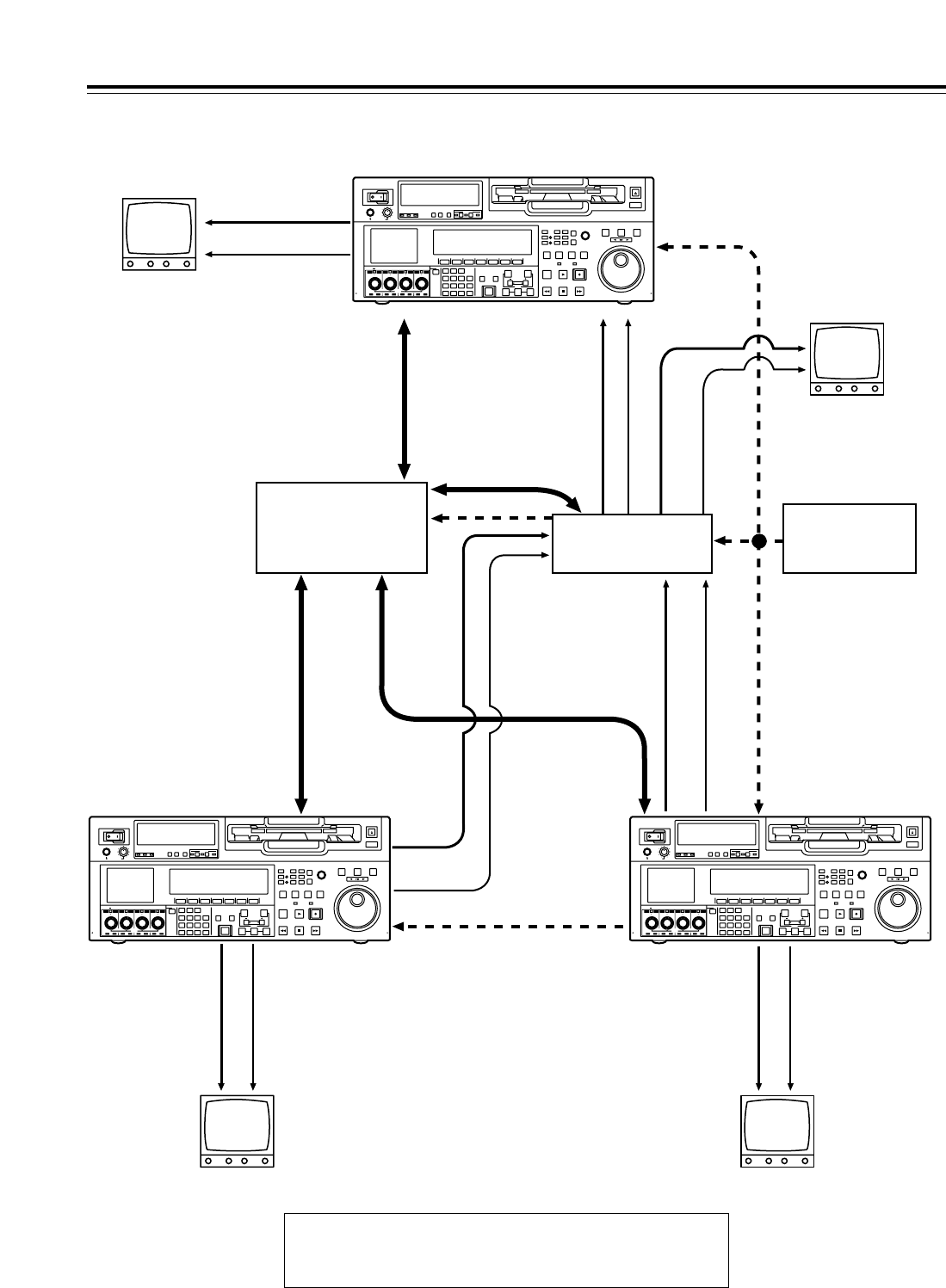
22
Example of connections with an editing controller
Connections
POWER
OFF
ON
HEADPHONES
PUSH
LOCK
FULL
CH CONDITION
MONITOR
FULL/FINE
REMOTE
LR
9P 50P
RS-232C
CH
12 3 4 5 6 7 8
CUE
XL/L/M
-
cassette
Do not insert S-cassette
without adapter
EJECT
AUDIO CH SELECT
SHIFT
ABC DEF GHI
JKL MNO PQRS
PREVIEW/
REVIEW
PRE-
ROLL
A IN A OUT
HOME RF1 ASSEM
ADJUST
SHTL
REV FWD
VARJOG
STAND BY
RECORDER INPUT CHECK
PLAYER
SERVO
EDIT PLAY REC
REW STOP FF
REC INHIBIT
PUSH-INTER
INSERT
RF2
VIDEO UNITY TC CUE
AUDIO UNITY DIAG MENU
TRIM
SET
IN
OUT
AUTO
EDIT
789
456BS
TUV WXYZ
123
ENT
0CTF
F1 F2 F3 F4 F5 F6
CH
1
CH
5
CH
2
CH
6
CH
3
CH
7
CH
4
CH
8
FULL
REC P8 REC P8 REC P8 REC P8
POWER
OFF
ON
HEADPHONES
PUSH
LOCK
FULL
CH CONDITION
MONITOR
FULL/FINE
REMOTE
LR
9P 50P
RS-232C
CH
12345678
CUE
XL/L/M
-
cassette
Do not insert S-cassette
without adapter
EJECT
AUDIO CH SELECT
SHIFT
ABC DEF GHI
JKL MNO PQRS
PREVIEW/
REVIEW
PRE-
ROLL
A IN A OUT
HOME RF1 ASSEM
ADJUST
SHTL
REV FWD
VARJOG
STAND BY
RECORDER INPUT CHECK
PLAYER
SERVO
EDIT PLAY REC
REW STOP FF
REC INHIBIT
PUSH-INTER
INSERT
RF2
VIDEO UNITY TC CUE
AUDIO UNITY DIAG MENU
TRIM
SET
IN
OUT
AUTO
EDIT
789
456BS
TUV WXYZ
123
ENT
0CTF
F1 F2 F3 F4 F5 F6
CH
1
CH
5
CH
2
CH
6
CH
3
CH
7
CH
4
CH
8
FULL
REC P8 REC P8 REC P8 REC P8
POWER
OFF
ON
HEADPHONES
PUSH
LOCK
FULL
CH CONDITION
MONITOR
FULL/FINE
REMOTE
LR
9P 50P
RS-232C
CH
12 3 4 5 6 7 8
CUE
XL/L/M
-
cassette
Do not insert S-cassette
without adapter
EJECT
AUDIO CH SELECT
SHIFT
ABC DEF GHI
JKL MNO PQRS
PREVIEW/
REVIEW
PRE-
ROLL
A IN A OUT
HOME RF1 ASSEM
ADJUST
SHTL
REV FWD
VARJOG
STAND BY
RECORDER INPUT CHECK
PLAYER
SERVO
EDIT PLAY REC
REW STOP FF
REC INHIBIT
PUSH-INTER
INSERT
RF2
VIDEO UNITY TC CUE
AUDIO UNITY DIAG MENU
TRIM
SET
IN
OUT
AUTO
EDIT
789
456BS
TUV WXYZ
123
ENT
0CTF
F1 F2 F3 F4 F5 F6
CH
1
CH
5
CH
2
CH
6
CH
3
CH
7
CH
4
CH
8
FULL
REC P8 REC P8 REC P8 REC P8
AV monitor
Av monitor
Av monitor
Source unit Source unit
Av monitor
Recorder
Video monitor signals
Video monitor signals
Audio monitor
signals
Audio monitor
signals
Audio monitor
signals
Video monitor
signals
Audio monitor
signals
Video monitor
signals
Remote signals
Remote signals
Remote signals
Video input signals
Video output signals
Video output signals
Audio input signals
Audio output signals
Audio output signals
Reference signal
Reference signal
Editing controller AV switcher
Reference signal
generator
To REMOTE IN/OUT
connector
To REMOTE IN/OUT
connector
To
REMOTE
IN/OUT
<Note>
When disconnecting the remote signals (9P) from one component
and re-connecting them to another component, check the settings,
etc. of the editing controller.
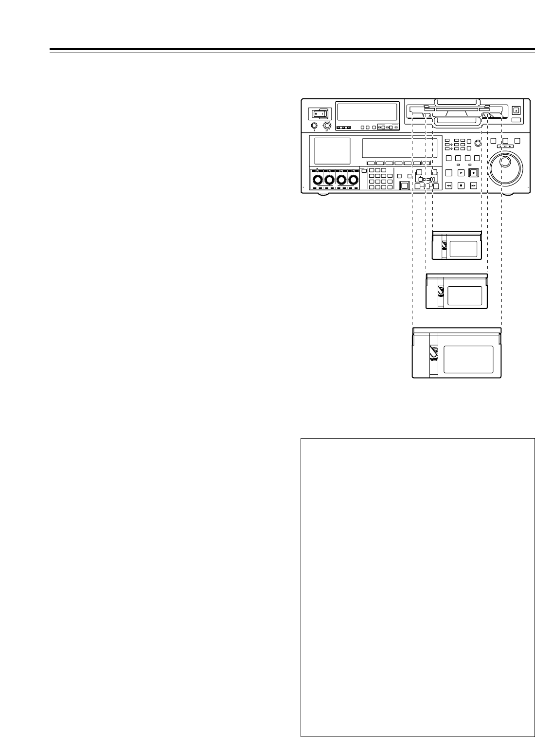
23
POWER
OFF
ON
HEADPHONES
PUSH
LOCK
FULL
CH CONDITION
MONITOR
FULL/FINE
REMOTE
LR
9P 50P
RS-232C
CH
12 3 4 5 6 7 8
CUE
XL/L/M
-
cassette
Do not insert S-cassette
without adapter
EJECT
AUDIO CH SELECT
SHIFT
ABC DEF GHI
JKL MNO PQRS
PREVIEW/
REVIEW
PRE-
ROLL
A IN A OUT
HOME RF1 ASSEM
ADJUST
SHTL
REV FWD
VARJOG
STAND BY
RECORDER INPUT CHECK
PLAYER
SERVO
EDIT PLAY REC
REW STOP FF
REC INHIBIT
PUSH-INTER
INSERT
RF2
VIDEO UNITY TC CUE
AUDIO UNITY DIAG MENU
TRIM
SET
IN
OUT
AUTO
EDIT
789
456BS
TUV WXYZ
123
ENT
0CT F
F1 F2 F3 F4 F5 F6
CH 1CH 5CH 2CH 6CH 3CH 7CH 4CH 8
FULL
REC P8 REC P8 REC P8 REC P8
L cassette size
XL cassette size
Consumer-use DV and DVCAM
cassettes
S cassettes
These tapes are exclusively designed for
consumer-use DV and DVCAM camera recorders.
They can be played using a cassette adapter
(optional accessory).
However, bear in mind that long-duration
cassette tapes (80 minutes in the standard
mode and 120 minutes in the LP mode) cannot
be used.
It is recommended that tapes bearing the
Panasonic brand be used as the consumer-use DV
tapes.
• Bear in mind that inserting a cassette tape
without the use of a cassette adapter will cause
malfunctioning.
M cassettes
DVCPRO HD LP:
Tapes capable of up to 32 minutes of recording and
playback
DVCPRO 25/50/50P/HD playback tapes
L cassettes
DVCPRO HD LP:
Tapes capable of up to 92 minutes of recording and
playback
DVCPRO 25/50/50P/HD playback tapes
For consumer-use DV or DVCAM applications:
These are playback tapes in the standard
consumer-use DV or DVCAM cassettes.
It is recommended that tapes bearing the
Panasonic brand be used as the consumer-use DV
tapes.
XL cassettes
DVCPRO HD LP:
Tapes capable of up to 126 minutes of recording
and playback
M cassette size
Concerning tapes
Align the cassette with the center of the insertion slot,
and push it in gently.
The cassette tape will be loaded automatically.
<Precautions when playing back consumer-use
DV and DVCAM tapes>
• It is not possible to play back consumer-use tapes
which have been recorded in the LP mode.
• The maximum transport speed of a consumer-use
DV or DVCAM cassette tape is 32k.
• The maximum still time for a consumer-use DV or
DVCAM cassette tape is 10 seconds.
• From the perspective of protecting consumer-use
DV and DVCAM cassette tapes, minimize the
number of times the tapes are cued up at the
same place as far as possible.
• When consumer-use DV and DVCAM cassette
tapes are used, the maximum time for STILL
TIMER is set to 10 seconds and the total time
elapsing when the VTR is left standing in the
STILL mode is set to 1 minute.
• When editing material which has been recorded
onto a consumer-use DV or DVCAM cassette
tape, first record the material onto a DVCPRO HD
tape or another VTR used for broadcasting
applications.
• Noise may occur when performing slow playback
using consumer-use DV or DVCAM cassette
tapes.
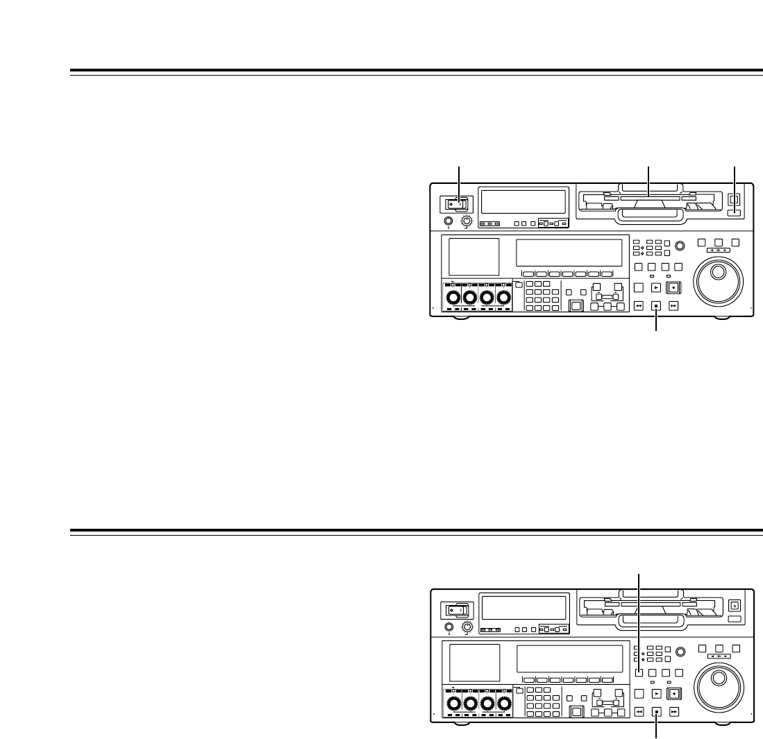
24
Before starting to operate the VTR, check whether the
equipment has been connected properly.
Turning on the power and inserting the cassette
1Turn on the VTR’s power.
3Insert the cassette tape.
Without forcing it, insert the cassette tape at the
prescribed position.
4Check that the STOP lamp is lighted.
When the tape is inserted, the cylinder starts
rotating automatically, the tape is loaded, and the
VTR is set to the STOP mode. The EJECT lamp
goes off.
2Check that the AUTO OFF lamp is off.
If condensation or some other problem has
occurred, the AUTO OFF lamp lights, and no
further operations can be performed.
POWER
OFF
ON
HEADPHONES
PUSH
LOCK
FULL
CH CONDITION
MONITOR
FULL/FINE
REMOTE
LR
9P 50P
RS-232C
CH
12 3 4 5 6 7 8
CUE
XL/L/M
-
cassette
Do not insert S-cassette
without adapter
EJECT
AUDIO CH SELECT
SHIFT
ABC DEF GHI
JKL MNO PQRS
PREVIEW/
REVIEW
PRE-
ROLL
A IN A OUT
HOME RF1 ASSEM
ADJUST
SHTL
REV FWD
VARJOG
STAND BY
RECORDER INPUT CHECK
PLAYER
SERVO
EDIT PLAY REC
REW STOP FF
REC INHIBIT
PUSH-INTER
INSERT
RF2
VIDEO UNITY TC CUE
AUDIO UNITY DIAG MENU
TRIM
SET
IN
OUT
AUTO
EDIT
789
456BS
TUV WXYZ
123
ENT
0CT F
F1 F2 F3 F4 F5 F6
CH
1
CH
5
CH
2
CH
6
CH
3
CH
7
CH
4
CH
8
FULL
REC P8 REC P8 REC P8 REC P8
1 23
4
STOP and STANDBY modes
1The VTR is set to the STOP mode when its STOP
button is pressed. The STOP lamp lights, and the
tape stops running.
•
In order to protect the tape, the VTR is set to
standby OFF after the time set by setup menu
item No.400 (STILL TIMER) has elapsed. If the
STOP, REW, FF or PLAY button is now
pressed, the VTR will be set to the
corresponding mode.
2The VTR is set to the STANDBY ON/OFF mode
when its STANDBY button is pressed. The
standby ON mode is established while the button’s
lamp is lighted. When the button is pressed in the
standby OFF mode, the VTR is set to the standby
ON mode.
When the button is pressed while the VTR is in the
STOP mode, it is set to the standby OFF mode
and the half-loading status, and the button’s lamp
goes off.
<Precautions for STILL TIMER setting>
The cumulative total standby time at the same place
increases when programs are transmitted or the same
material is used repeatedly. In order to protect the
tape, keep the standby time at the same place on the
tape as short as possible by, for instance, selecting a
maximum of 30 seconds or so as the setup menu item
No.400 (STILL TIMER) setting.
POWER
OFF
ON
HEADPHONES
PUSH
LOCK
FULL
CH CONDITION
MONITOR
FULL/FINE
REMOTE
LR
9P 50P
RS-232C
CH
12345678
CUE
XL/L/M
-
cassette
Do not insert S-cassette
without adapter
EJECT
AUDIO CH SELECT
SHIFT
ABC DEF GHI
JKL MNO PQRS
PREVIEW/
REVIEW
PRE-
ROLL
A IN A OUT
HOME RF1 ASSEM
ADJUST
SHTL
REV FWD
VARJOG
STAND BY
RECORDER INPUT CHECK
PLAYER
SERVO
EDIT PLAY REC
REW STOP FF
REC INHIBIT
PUSH-INTER
INSERT
RF2
VIDEO UNITY TC CUE
AUDIO UNITY DIAG MENU
TRIM
SET
IN
OUT
AUTO
EDIT
789
456BS
TUV WXYZ
123
ENT
0CT F
F1 F2 F3 F4 F5 F6
CH
1
CH
5
CH
2
CH
6
CH
3
CH
7
CH
4
CH
8
FULL
REC P8 REC P8 REC P8 REC P8
2
1

25
Recording
1Set the accidental erasure prevention tab on the
cassette tape to the “recording” position, and insert
the tape.
3Select “EE” as the OUTPUT setting using on
the <HOME> menu. E-E pictures now appear on
the TV monitor.
F1
4Check that the REC INHIBIT lamp is off.
If the lamp is lighted, select “OFF” as the R INH
setting using on the <HOME> menu.
If the inserted cassette has already been recorded
on using a format other than DVCPRO HD-LP, the
recording inhibited status (factory setting) will be
set by setup menu item No.118.
F6
6Press the PLAY button while holding down the
REC button.
The REC and PLAY lamps light, and recording
starts.
7When the STOP button is pressed, the recording
ends, and the VTR is set to the stop mode.
<Notes>
•
During recording, check that the SERVO lamp is
lighted. The playback pictures will be disturbed if it
is blinking or off.
•
If analog signals (ANA1 to ANA4) have been
selected as the CH5 to CH8 input signals on the
AUDIO menu, their recording levels are tied in with
the recording levels which have been set for the
CH1 to CH4 signals.
•
When SDTI has been selected as the video signals
to be recorded, the audio signals which will be
recorded are also automatically set to SDTI.
5Select the video and audio input signals, and
adjust the audio levels.
Selecting the video and audio input signals
1Connect the signals to be recorded.
2Select the input signals using on the
<VIDEO> menu and to on the
<AUDIO> menu or <AUDIO SHIFT1> menu.
Adjust the audio levels
1Adjust the audio input levels of the CH1, CH2,
CH3, CH4, CH5, CH6, CH7, CH8 audio signals
and analog cue signal selected on the AUDIO
menu.
When the audio UNITY lamp on the front panel
is lighted, the audio signals will be recorded at
the appropriate levels.
2Before adjusting the recording level, check that
the REC LED is lighted and that the audio
adjustment dial is in the unlocked status (LOCK
LED off).
If the dial is in the LOCK status (LOCK LED
lighted), press it. The LOCK LED goes off, and
the lock is released.
In addition, the analog cue audio recording level
is adjusted using setup menu item No.790 (CUE
REC VOL) so that it will not exceed j20 dB.
F6F1
F1
2Press the STOP button to set the VTR to the stop
mode.

26
Playback
1Insert the cassette tape, and set the VTR to the
STOP mode.
3Adjust the audio playback levels.
Before adjusting the playback levels, check that
the PB LED is lighted and that the audio
adjustment dial is in the unlocked status. If the dial
is locked (indicated by the lighted LOCK LED),
press it. The LOCK LED goes off, and the lock is
released. The analog cue audio level is adjusted
using setup menu item No.791 (CUE PB VOL).
Normally, the VTR is kept in the UNITY status (the
segment display of the control lights at the center).
4To end the playback, press the STOP button. The
VTR is now set to the STOP mode.
<Note>
During playback, check that the SERVO lamp is
lighted. The playback pictures will be disturbed if the
lamp is off or blinking.
2Press the PLAY button.
Normal playback commences.
Playback phase adjustment function
If two VTRs are to be used to play the same program,
the playback phase between the VTRs can be
adjusted by changing the playback speed of one of
the VTRs.
1Press the TRIM button (“i” or “j” button) while
holding down the PLAY button. Each time it is
pressed, the playback speed is accelerated or
decelerated in increments of the number of
playback framing fields selected by the setup menu
item No.109 (CAP.LOCK) setting.
The SERVO lamp remains off while the tape is
being played at the accelerated or decelerated
speed.
2Upon completion of the playback phase
adjustment, release the PLAY button.
The VTRs now return to the standard playback
speed, and the SERVO lamp lights.

27
Jog mode
Jog/Shuttle
1Press the JOG button.
Shuttle mode
1Press the SHTL button.
3To transfer the VTR from the jog mode to another
mode, press the button that corresponds to the
mode concerned.
2Turn the search dial.
The dial’s click-stops are released, and the tape is
played back at the speed corresponding to the
speed at which the dial is turned.
The maximum jog speed can be changed by
selecting the setup menu item No.310 (JOG FWD
MAX) and No.311 (JOG REV MAX) settings.
When the dial is no longer turned, a still picture will
appear.
2Turn the search dial.
The playback picture speed changes from 0 up to
w32kdepending on the dial position.
This speed can be switched to w9.8k, w16kor
w32kusing setup menu item No.101 (SHTL
MAX).
The dial has a click-stop at the center position
where a still picture will appear.
3To transfer the VTR from the shuttle mode to
another mode, press the STOP button or the
button of the mode concerned.
Variable mode
1Press the VAR button.
3To transfer the VTR from the variable mode to
another mode, press the STOP button or the
button of the mode concerned.
2Turn the search dial.
The playback picture speed changes from j4.9k
to i4.9kdepending on the dial position.
The maximum shuttle speed can be changed by
selecting the setup menu item No.308 (VAR FWD
MAX) and No.309 (VAR REV MAX) settings.
Noise will be generated at all speeds other than
j1kto i2k. (For all tapes other than DVCPRO
HD-LP recorded ones, the noise-free speed range
is j1.0kto i1.1k.)
<Note>
At the factory setting, the VTR is set to be transferred
to the shuttle mode, jog mode or variable mode when
the search dial is turned.
In cases where it is not convenient for the VTR to be
transferred directly to the variable speed mode, it can
be transferred via the search button. Select “KEY” as
the setup menu item No.100 (SEARCH ENA) setting.

28
Manual Editing
1Select the editing mode.
ASSEM button:
Assemble (frame-to-frame continuity) editing is
performed using this button.
INSERT button:
Insert editing is performed using this button.
2On the time code display, select the channels to be
edited.
ASSEM:
Set ASSEM to ON using the button.
INSERT:
To select V, A1, A2, A3, A4 and CUE channels,
press the to buttons; to select A5, A6, A7,
A8 and TC channels, press the + to
+ buttons. The highlighted channels
will now be edited.
F6SHIFT
F2SHIFT
F6F1
F1
3Press the PLAY button.
4While monitoring the TV monitor, search the
position where the editing is to be started (IN
point), and press the PLAY and EDIT buttons
together at this position.
5Similarly, while monitoring the TV monitor, search
the position where the editing is to be terminated
(OUT point), and press the PLAY or STOP button
at this position. The VTR is set to the PLAY or
STOP mode, and the editing is terminated.
Preroll
1Press the PREROLL button.
The VTR now performs the preroll operation.
When the cue time has been registered on the
HOME, PF1 or PF2 screen:
The tape is prerolled from the registered cue time
using the preroll time which was set using
(PREROL) on the <HOME SHIFT> menu.
When the search mode is established on the
CUE screen:
The tape is prerolled from the selected cue point
using the preroll time which was set using
(CU-ROL) on the <CUE SHIFT> menu.
The preroll operation is not performed when the
selected cue point has not been registered or when
the cue point registration mode is established.
In all other situations:
The tape is prerolled from the registered IN point
(or the current tape position when the IN point has
not been registered) using the preroll time which
was set using (PREROL) on the <HOME
SHIFT> menu.
If the PREROLL button is pressed when the IN
point has not been registered, the current tape
position is automatically registered as the IN point
(but only when ENA has been selected as the
setup menu item No.305 (AUTO ENTRY) setting).
F1
F5
F1
<Note>
The time code or CTL signal must be continuously
recorded between the edit IN point and preroll point.
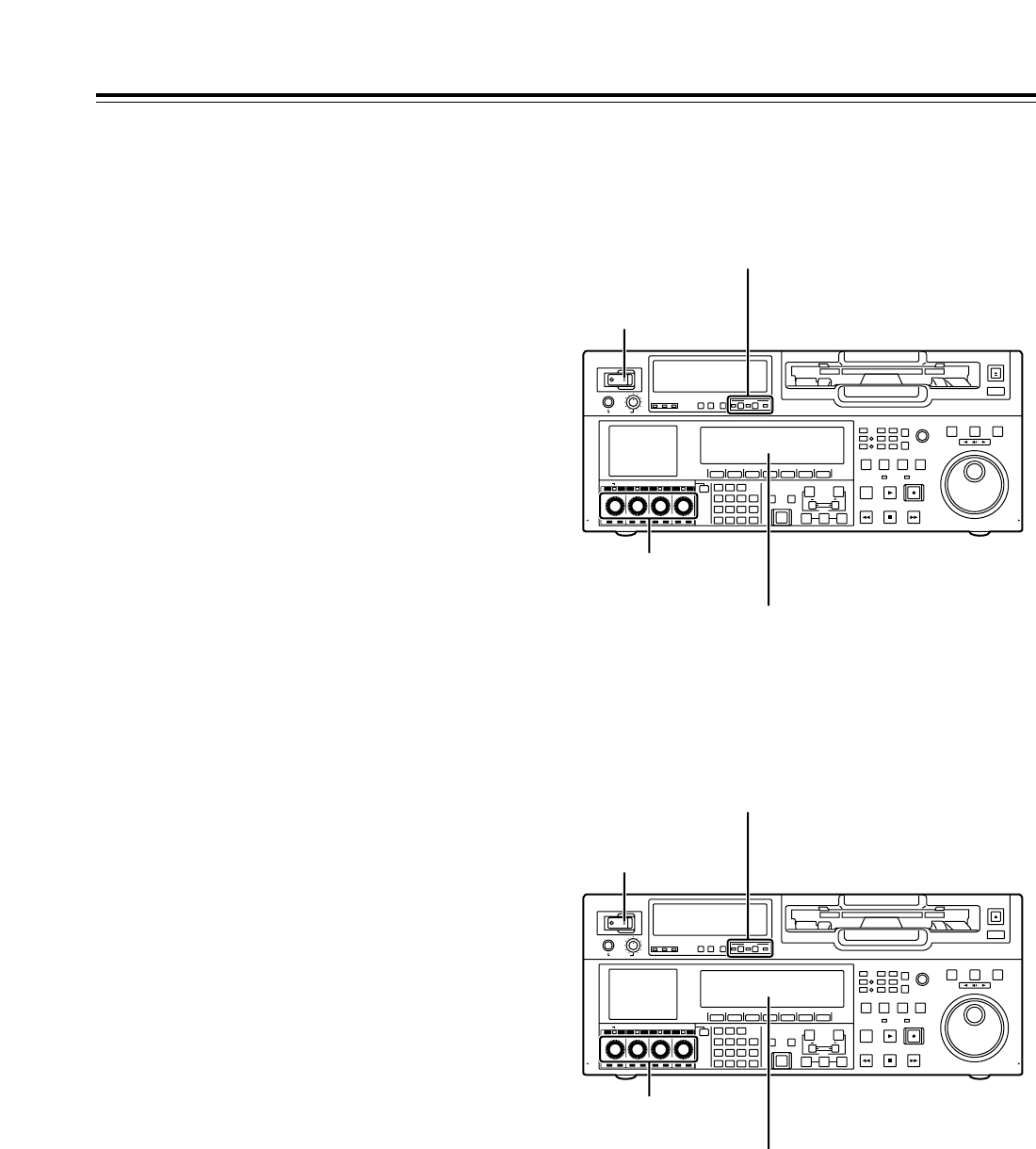
29
POWER
OFF
ON
HEADPHONES
PUSH
LOCK
FULL
CH CONDITION
MONITOR
FULL/FINE
REMOTE
LR
9P 50P
RS-232C
CH
12 3 4 5 6 7 8
CUE
XL/L/M
-
cassette
Do not insert S-cassette
without adapter
EJECT
AUDIO CH SELECT
SHIFT
ABC DEF GHI
JKL MNO PQRS
PREVIEW/
REVIEW
PRE-
ROLL
A IN A OUT
HOME RF1 ASSEM
ADJUST
SHTL
REV FWD
VARJOG
STAND BY
RECORDER INPUT CHECK
PLAYER
SERVO
EDIT PLAY REC
REW STOP FF
REC INHIBIT
PUSH-INTER
INSERT
RF2
VIDEO UNITY TC CUE
AUDIO UNITY DIAG MENU
TRIM
SET
IN
OUT
AUTO
EDIT
789
456BS
TUV WXYZ
123
ENT
0CT F
F1 F2 F3 F4 F5 F6
CH
1
CH
5
CH
2
CH
6
CH
3
CH
7
CH
4
CH
8
FULL
REC P8 REC P8 REC P8 REC P8
Switch settings and adjustments
When using this VTR as the recorder
Automatic Editing (deck-to-deck)
1Using the REMOTE button, set the player to
REMOTE and the recorder to LOCAL (ensure that
the REMOTE LED is not lighted).
2Select the editing mode (ASSEM or INSERT).
3
Register the edit points of the recorder and player.
4Check and modify, if necessary, the edit points.
5Preview the material before editing it.
6Proceed with the editing.
7Review the edited results.
“Editing” refers to the work involved in using pre-
recorded tapes to bring different contents together or
delete unnecessary parts and bring together only the
necessary parts.
The basic editing steps are as follows.
Set the POWER
switch to ON.
Adjust the recording
levels.
Switch the time counter display to TC
or CTL.
Set the VTR to the LOCAL status (which is
indicated when the REMOTE LED is OFF).
POWER
OFF
ON
HEADPHONES
PUSH
LOCK
FULL
CH CONDITION
MONITOR
FULL/FINE
REMOTE
LR
9P 50P
RS-232C
CH
12 3 4 5 6 7 8
CUE
XL/L/M
-
cassette
Do not insert S-cassette
without adapter
EJECT
AUDIO CH SELECT
SHIFT
ABC DEF GHI
JKL MNO PQRS
PREVIEW/
REVIEW
PRE-
ROLL
A IN A OUT
HOME RF1 ASSEM
ADJUST
SHTL
REV FWD
VARJOG
STAND BY
RECORDER INPUT CHECK
PLAYER
SERVO
EDIT PLAY REC
REW STOP FF
REC INHIBIT
PUSH-INTER
INSERT
RF2
VIDEO UNITY TC CUE
AUDIO UNITY DIAG MENU
TRIM
SET
IN
OUT
AUTO
EDIT
789
456BS
TUV WXYZ
123
ENT
0CT F
F1 F2 F3 F4 F5 F6
CH
1
CH
5
CH
2
CH
6
CH
3
CH
7
CH
4
CH
8
FULL
REC P8 REC P8 REC P8 REC P8
When using this VTR as the player
Set the POWER
switch to ON.
Adjust the playback
levels.
Switch the time counter display to TC
or CTL.
Press the 9P button for 2 or more seconds
to set the VTR to the REMOTE status which
is indicated when the REMOTE LED is ON).
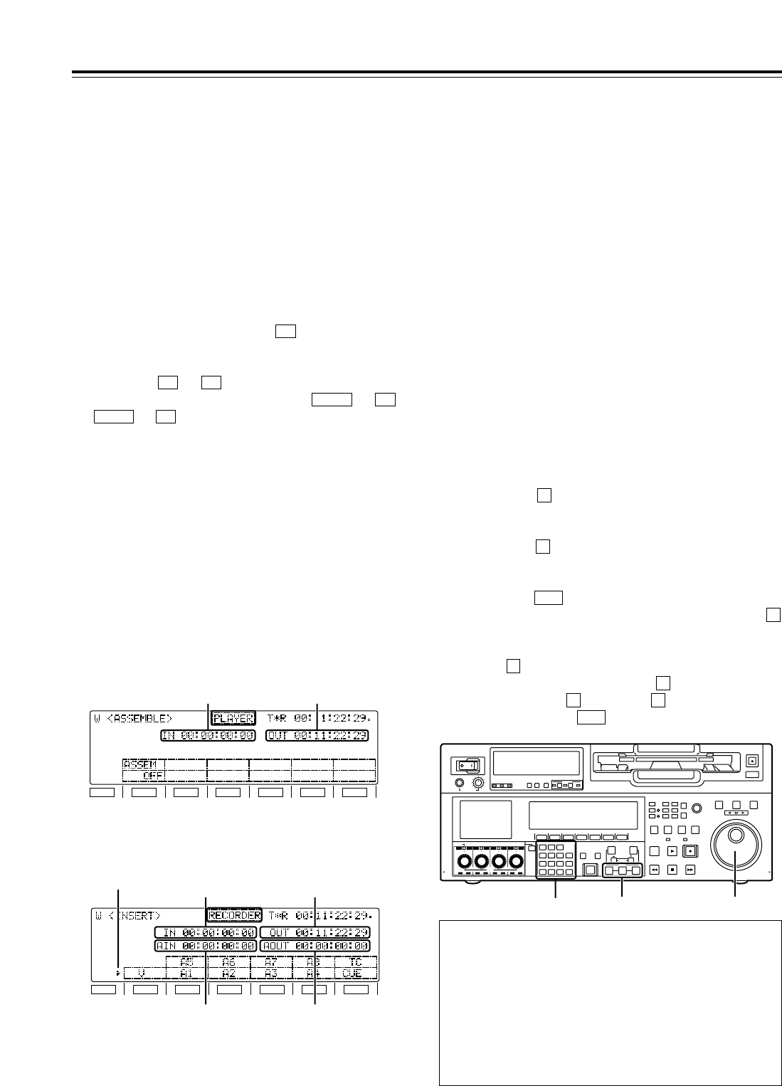
30
Automatic Editing (deck-to-deck)
1Select the editing mode.
ASSEM button:
Assemble (frame-to-frame continuity) editing is
performed in this mode.
INSERT button:
Insert editing is performed in this mode.
2On the time code display, select the channels to be
edited.
ASSEM:
Set ASSEM to ON using the button.
INSERT:
To select V, A1, A2, A3, A4 and CUE channels,
press the to buttons; to select A5, A6, A7,
A8 and TC channels, press the + to
+ buttons. The highlighted channels
will now be edited.
F6SHIFT
F2SHIFT
F6F1
F1
3Press the PLAYER or RECORDER button to select
the VTR which is to be operated.
[Setting for editing using two VTRs]
PLAYER:
Press this button if the player VTR is to be
operated to register the edit points.
RECORDER:
Press this button if the recorder VTR (this VTR) is
to be operated to register the edit points.
F1
SHIFT
F2 F3 F4 F5 F6
[ASSEM screen]
IN point OUT point
F1
SHIFT
F2 F3 F4 F5 F6
[INSERT screen]
IN point OUT point
AUDIO IN point
Marker
AUDIO OUT point
1Locate the edit IN point by performing the jog or
shuttle operation. Set the tape to the still picture
status at the desired position.
For a detailed description of the jog and shuttle
operations, refer to page 27.
2Press the IN button and SET button together.
The edit IN point is now registered.
The edit IN point value appears on the display.
4Press the OUT button and SET button together.
The edit OUT point is now registered.
The edit OUT point value appears on the display.
5
3Locate the edit OUT point by performing the jog or
shuttle operation. Set the tape to the still picture
status at the desired position.
Registering the edit pointsSelecting the editing mode
Match frame processing function
When two VTRs are used to perform the editing
operations, there will be a total of 4 edit points: the IN
and OUT points for the player and the IN and OUT points
for the recorder. However, the last point is automatically
calculated so only three of the edit points need to be
registered.
Negative duration function
Use setup menu items No.300 (IN/OUT DEL) and
No.301 (NEGA FLASH) in combination.
POWER
OFF
ON
HEADPHONES
PUSH
LOCK
FULL
CH CONDITION
MONITOR
FULL/FINE
REMOTE
LR
9P 50P
RS-232C
CH
12345678
CUE
XL/L/M
-
cassette
Do not insert S-cassette
without adapter
EJECT
AUDIO CH SELECT
SHIFT
ABC DEF GHI
JKL MNO PQRS
PREVIEW/
REVIEW
PRE-
ROLL
A IN A OUT
HOME RF1 ASSEM
ADJUST
SHTL
REV FWD
VARJOG
STAND BY
RECORDER INPUT CHECK
PLAYER
SERVO
EDIT PLAY REC
REW STOP FF
REC INHIBIT
PUSH-INTER
INSERT
RF2
VIDEO UNITY TC CUE
AUDIO UNITY DIAG MENU
TRIM
SET
IN
OUT
AUTO
EDIT
789
456BS
TUV WXYZ
123
ENT
0CT F
F1 F2 F3 F4 F5 F6
CH
1
CH
5
CH
2
CH
6
CH
3
CH
7
CH
4
CH
8
FULL
REC P8 REC P8 REC P8 REC P8
1, 32, 4
5
The edit points can be registered directly using the
number keys.
1. Select the <ASSEMBLE> or <INSERT> menu.
2. Press the button to highlight the edit point. Turn
the ADJUST dial to move the highlighting to the IN
point or OUT point.
3. Press the button again, and input the desired edit
point directly using the number keys. Turn the
ADJUST dial to move from one digit to the next.
4. Press the button to register the point.
To abort the registration at any time, press the
button.
To reset a particular edit point (to 00:00:00:00), press
the button, align the highlighting with the edit
point concerned, and press the button again.
Next, press the button and button together.
Finally, press the button to register the point.
ENT
0F
T
T
C
ENT
T
T
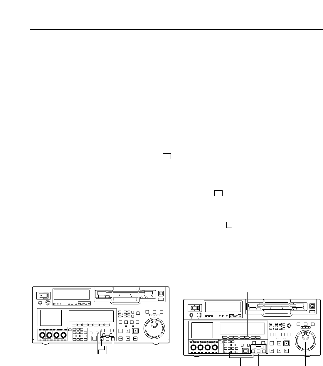
31
1Re-registering an edit point
Locate the new edit point by performing the jog or
shuttle operation, and press the IN (or OUT) button
and SET button at the same time to re-register the
edit point.
2Modifying an edit point in 1-frame increments
(trimming function)
Press the TRIM button while holding down the IN
(or OUT) button.
Each time the ibutton is pressed, the point is
moved ahead by one frame.
Conversely, each time the jbutton is pressed, the
point is moved back by one frame.
3Resetting edit points
1Resetting both an edit IN point and OUT
point
Press (TC CLR = RESET) on the <HOME>
menu.
(This takes effect only in the CTL mode.)
2Resetting either an edit IN point or OUT point
Press the button among the number keys
while holding down the IN (or OUT) button.
<Notes>
• An edit OUT point can be reset even while
editing is in progress.
• In the eject mode, the IN and OUT points are
automatically reset.
C
F4
Modifying edit points
Automatic Editing (deck-to-deck)
1Press the IN (or OUT) button to check the edit
point.
The value of the registered edit point appears on
the display.
2While holding down the IN (or OUT) button, press
the PREROLL button to check the picture at the
edit point.
The tape is cued up to the edit IN (or OUT) point,
and a still picture of the point appears.
•If “STOP” has been selected as the setup menu
item No.307 (AFTER CUE-UP) setting, the VTR
is set to the E-E mode provided that EE has
been selected as the <HOME> menu
(OUTPUT) setting.
F1
3By holding down the IN and OUT buttons at the
same time, check the editing duration. The
duration appears on the display.
How the duration is calculated
• When two edit points have been set
The duration between the two points is
calculated.
• When only one edit point has been set
The duration between the data which has been
set and the current address is calculated.
• When no edit points have been set
The duration of the previously edited section is
calculated.
Checking the edit points
POWER
OFF
ON
HEADPHONES
PUSH
LOCK
FULL
CH CONDITION
MONITOR
FULL/FINE
REMOTE
LR
9P 50P
RS-232C
CH
12345678
CUE
XL/L/M
-
cassette
Do not insert S-cassette
without adapter
EJECT
AUDIO CH SELECT
SHIFT
ABC DEF GHI
JKL MNO PQRS
PREVIEW/
REVIEW
PRE-
ROLL
A IN A OUT
HOME RF1 ASSEM
ADJUST
SHTL
REV FWD
VARJOG
STAND BY
RECORDER INPUT CHECK
PLAYER
SERVO
EDIT PLAY REC
REW STOP FF
REC INHIBIT
PUSH-INTER
INSERT
RF2
VIDEO UNITY TC CUE
AUDIO UNITY DIAG MENU
TRIM
SET
IN
OUT
AUTO
EDIT
789
456BS
TUV WXYZ
123
ENT
0CT F
F1 F2 F3 F4 F5 F6
CH
1
CH
5
CH
2
CH
6
CH
3
CH
7
CH
4
CH
8
FULL
REC P8 REC P8 REC P8 REC P8
2 1, 3
POWER
OFF
ON
HEADPHONES
PUSH
LOCK
FULL
CH CONDITION
MONITOR
FULL/FINE
REMOTE
LR
9P 50P
RS-232C
CH
12 3 4 5 6 7 8
CUE
XL/L/M
-
cassette
Do not insert S-cassette
without adapter
EJECT
AUDIO CH SELECT
SHIFT
ABC DEF GHI
JKL MNO PQRS
PREVIEW/
REVIEW
PRE-
ROLL
A IN A OUT
HOME RF1 ASSEM
ADJUST
SHTL
REV FWD
VARJOG
STAND BY
RECORDER INPUT CHECK
PLAYER
SERVO
EDIT PLAY REC
REW STOP FF
REC INHIBIT
PUSH-INTER
INSERT
RF2
VIDEO UNITY TC CUE
AUDIO UNITY DIAG MENU
TRIM
SET
IN
OUT
AUTO
EDIT
789
456BS
TUV WXYZ
123
ENT
0CT F
F1 F2 F3 F4 F5 F6
CH
1
CH
5
CH
2
CH
6
CH
3
CH
7
CH
4
CH
8
FULL
REC P8 REC P8 REC P8 REC P8
1
31
2
32
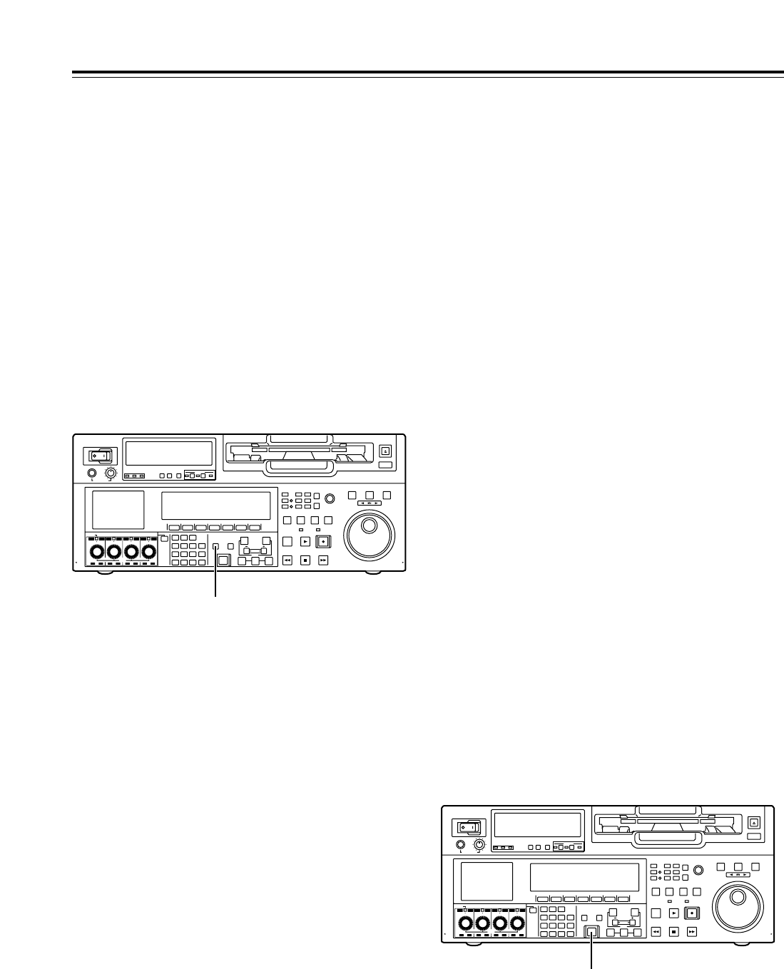
32
Automatic Editing (deck-to-deck)
Previewing
1After the edit points have been registered, press
the PREVIEW button.
Regular preview is now conducted.
<Notes>
• If the edit IN point has not been registered, the
position where the PREVIEW button was
pressed is registered as the edit IN point.
• To stop the preview at any time, press the
STOP button.
• When the PREVIEW button is pressed again
after the IN point during the course of a preview,
the preview will start again from the beginning.
• When the edit OUT point is reached, the tape is
postrolled, after which it stops automatically.
POWER
OFF
ON
HEADPHONES
PUSH
LOCK
FULL
CH CONDITION
MONITOR
FULL/FINE
REMOTE
LR
9P 50P
RS-232C
CH
12345678
CUE
XL/L/M
-
cassette
Do not insert S-cassette
without adapter
EJECT
AUDIO CH SELECT
SHIFT
ABC DEF GHI
JKL MNO PQRS
PREVIEW/
REVIEW
PRE-
ROLL
A IN A OUT
HOME RF1 ASSEM
ADJUST
SHTL
REV FWD
VARJOG
STAND BY
RECORDER INPUT CHECK
PLAYER
SERVO
EDIT PLAY REC
REW STOP FF
REC INHIBIT
PUSH-INTER
INSERT
RF2
VIDEO UNITY TC CUE
AUDIO UNITY DIAG MENU
TRIM
SET
IN
OUT
AUTO
EDIT
789
456BS
TUV WXYZ
123
ENT
0CT F
F1 F2 F3 F4 F5 F6
CH
1
CH
5
CH
2
CH
6
CH
3
CH
7
CH
4
CH
8
FULL
REC P8 REC P8 REC P8 REC P8
1
1Press the AUTO EDIT button.
Automatic editing is now executed.
• To suspend editing at any time, press the STOP
button.
• When the edit OUT point is reached, the tape is
postrolled, after which it stops.
Postrolling
In the case of assemble editing, editing continues
for about 2 seconds after the edit OUT point is
passed, and the tape is then returned to the OUT
point, after which it stops.
In the case of insert editing, the PLAY mode is
established after the edit OUT point has been
passed, and the tape is then returned to the OUT
point, after which it stops.
Retry function
Even when the STOP button has been pressed to
suspend editing, editing can be repeated from the
beginning simply by pressing the AUTO EDIT
button again.
Auto tag function
If, upon completion of editing, when the AUTO
EDIT button is pressed although the next edit point
has not yet been registered, the previous edit OUT
point is registered as the IN point, and editing is
executed.
To release the auto tag mode, press one of the
transport system buttons (such as the PLAY
button).
<Note>
The registered points are automatically cleared
after editing has been executed. However, the
previous edit points can be recalled by pressing
the TRIMi(or TRIMj) button and SET button at
the same time.
Automatic editing
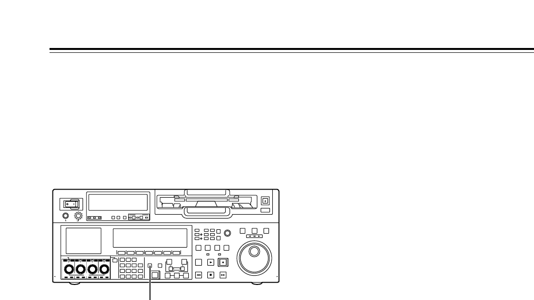
33
1Upon completion of the editing, press the REVIEW
button.
Review is now started by the recorder.
• To stop the review at any time, press the STOP
button.
• When the edit OUT point is reached, the tape is
postrolled, after which it stops.
Reviewing
Automatic Editing (deck-to-deck)
POWER
OFF
ON
HEADPHONES
PUSH
LOCK
FULL
CH CONDITION
MONITOR
FULL/FINE
REMOTE
LR
9P 50P
RS-232C
CH
12345678
CUE
XL/L/M
-
cassette
Do not insert S-cassette
without adapter
EJECT
AUDIO CH SELECT
SHIFT
ABC DEF GHI
JKL MNO PQRS
PREVIEW/
REVIEW
PRE-
ROLL
A IN A OUT
HOME RF1 ASSEM
ADJUST
SHTL
REV FWD
VARJOG
STAND BY
RECORDER INPUT CHECK
PLAYER
SERVO
EDIT PLAY REC
REW STOP FF
REC INHIBIT
PUSH-INTER
INSERT
RF2
VIDEO UNITY TC CUE
AUDIO UNITY DIAG MENU
TRIM
SET
IN
OUT
AUTO
EDIT
789
456BS
TUV WXYZ
123
ENT
0CT F
F1 F2 F3 F4 F5 F6
CH
1
CH
5
CH
2
CH
6
CH
3
CH
7
CH
4
CH
8
FULL
REC P8 REC P8 REC P8 REC P8
1
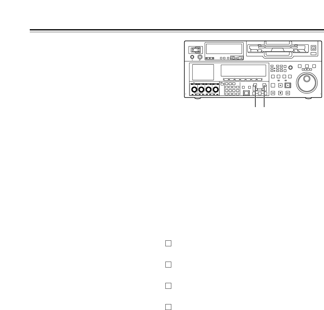
34
∫Modifying the edit points
Video IN point:
While holding down the IN button, press the TRIMi
button or TRIMjbutton.
Video OUT point:
While holding down the OUT button, press the
TRIMibutton or TRIMjbutton.
Audio IN point:
While holding down the A-IN button, press the
TRIMibutton or TRIMjbutton.
Audio OUT point:
While holding down the A-OUT button, press the
TRIMibutton or TRIMjbutton.
∫Cueing the tape up to the edit points
Cue-up to video IN point:
While holding down the IN button, press the
PREROLL button.
Cue-up to video OUT point:
While holding down the OUT button, press the
PREROLL button.
Cue-up to audio IN point:
While holding down the A-IN button, press the
PREROLL button.
Cue-up to audio OUT point:
While holding down the A-OUT button, press the
PREROLL button.
The video edit points and audio edit points can be
registered independently, and editing can be executed
with the video points offset from the audio points.
Audio edit points cannot be registered when the
assemble editing mode has been selected.
After registering the edit points, proceed with the
same operations as for insert editing.
∫Registering the edit points
Video IN point:
While holding down the IN button, press the SET
button.
Video OUT point:
While holding down the OUT button, press the SET
button.
Audio IN point:
While holding down the A-IN button, press the SET
button.
Audio OUT point:
While holding down the A-OUT button, press the
SET button.
<Note>
If the editing mode is changed to assemble editing
after the audio edit points have been registered, the
audio edit points will be cleared.
∫Clearing the edit points
Video IN point:
While holding down the IN button, press the
button among the number keys.
Video OUT point:
While holding down the OUT button, press the
button among the number keys.
Audio IN point:
While holding down the A-IN button, press the
button among the number keys.
Audio OUT point:
While holding down the A-OUT button, press the
button among the number keys.
C
C
C
C
Audio Split Editing
A-IN button A-OUT button
POWER
OFF
ON
HEADPHONES
PUSH
LOCK
FULL
CH CONDITION
MONITOR
FULL/FINE
REMOTE
LR
9P 50P
RS-232C
CH
12345678
CUE
XL/L/M
-
cassette
Do not insert S-cassette
without adapter
EJECT
AUDIO CH SELECT
SHIFT
ABC DEF GHI
JKL MNO PQRS
PREVIEW/
REVIEW
PRE-
ROLL
A IN A OUT
HOME RF1 ASSEM
ADJUST
SHTL
REV FWD
VARJOG
STAND BY
RECORDER INPUT CHECK
PLAYER
SERVO
EDIT PLAY REC
REW STOP FF
REC INHIBIT
PUSH-INTER
INSERT
RF2
VIDEO UNITY TC CUE
AUDIO UNITY DIAG MENU
TRIM
SET
IN
OUT
AUTO
EDIT
789
456BS
TUV WXYZ
123
ENT
0CT F
F1 F2 F3 F4 F5 F6
CH
1
CH
5
CH
2
CH
6
CH
3
CH
7
CH
4
CH
8
FULL
REC P8 REC P8 REC P8 REC P8

35
Audio Split Editing
∫Duration display
The duration can be indicated on the display.
Between the video IN and OUT points:
Press the IN button and OUT button at the same
time.
Between the audio IN and OUT points:
Press the A-IN button and A-OUT button at the
same time.
Match frame processing function
When two VTRs are used to perform the audio split
editing operations, there will be a total of 8 edit
points: the video IN and OUT points for the player,
the video IN and OUT points for the recorder, the
audio IN and OUT points for the player, and the
audio IN and OUT points for the recorder.
When five of the eight edit points are registered, the
remaining three points are automatically calculated
so only five of the edit points can be registered.
∫When a VTR not equipped with the split
editing function is used as the player
When a VTR for which the video and audio edit
points cannot be set independently is used as the
player, split editing is still possible by setting the
audio IN point and OUT point in the recorder and
setting the data of three points as the video edit
points.
<Note>
If, during audio split editing, the video OUT point (or
audio OUT point) only is registered without the
audio OUT (or video OUT point) having been
registered and automatic editing is then executed,
editing will continue until either the audio OUT point
(or video OUT point) is registered or the STOP
button is pressed to suspend the editing operation.
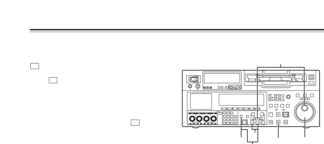
36
Variable memory function
1Register the IN point using the SET button and IN
button. There is no need to set the OUT point for
variable memory playback.
Variable memory playback operation procedure
The variable memory mode can be selected by setting
(VARMEM) on the <HOME SHIFT> menu to
“ON.”
When (VARMEM) is set to “OFF,” the variable
memory mode is canceled, and the regular mode is
established.
<Note>
Bear in mind that when the 23/24 Hz or 25 Hz (HD or
SD) mode has been selected as the system menu
item No.25 (SYSTEM FREQ) setting, (VARMEM)
will no longer appear on the display and the variable
memory mode cannot be selected.
F6
F6
F6
2Set the initial speed (j1.0kto i2.0k) using the
search dial while holding down the SET button.
3When the SET button and PREVIEW/REVIEW
button are pressed at the same time, the tape is
automatically prerolled and played back at the
initial speed setting up to the IN point.
4After the tape has passed the IN point, turn the
search dial to store the playback speed in the
memory.
5Press the STOP button to stop the tape.
6When the PREVIEW/REVIEW button is pressed,
variable memory playback is performed at the
memorized speed.
Variable memory function selection
This VTR is provided with two variable memory
functions, as follows. These functions can be used in
the variable memory mode.
Variable memory playback:
Any section of the tape can be played back at variable
speeds in the VAR mode, the changes in the speed
can be stored in the memory, and the tape can be
played back at the memorized speed.
Variable memory editing:
Using the VTR as a controller (recorder in the deck-to-
deck mode) to control the playback speed of the
player, editing can be performed in the variable speed
mode.
Outline To perform variable memory playback operations, set
the VTR to the variable memory mode, and take the
steps below.
<Notes>
• After passing the IN point, the tape is played back
in accordance with the settings in the memory, and
it continues to run at the last speed stored in the
memory until the STOP button is pressed.
• Whatever is stored in the memory will be cleared
when the VTR exits the variable memory mode. It
is also cleared when the POWER switch is set to
“OFF.”
POWER
OFF
ON
HEADPHONES
PUSH
LOCK
FULL
CH CONDITION
MONITOR
FULL/FINE
REMOTE
LR
9P 50P
RS-232C
CH
12345678
CUE
XL/L/M
-
cassette
Do not insert S-cassette
without adapter
EJECT
AUDIO CH SELECT
SHIFT
ABC DEF GHI
JKL MNO PQRS
PREVIEW/
REVIEW
PRE-
ROLL
A IN A OUT
HOME RF1 ASSEM
ADJUST
SHTL
REV FWD
VARJOG
STAND BY
RECORDER INPUT CHECK
PLAYER
SERVO
EDIT PLAY REC
REW STOP FF
REC INHIBIT
PUSH-INTER
INSERT
RF2
VIDEO UNITY TC CUE
AUDIO UNITY DIAG MENU
TRIM
SET
IN
OUT
AUTO
EDIT
789
456BS
TUV WXYZ
123
ENT
0CT F
F1 F2 F3 F4 F5 F6
CH
1
CH
5
CH
2
CH
6
CH
3
CH
7
CH
4
CH
8
FULL
REC P8 REC P8 REC P8 REC P8
156 4
2
3
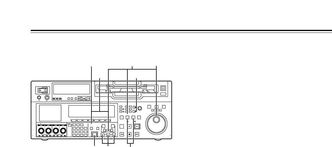
37
1Select the editing mode on the <ASSEMBLE> or
<INSERT> menu.
2Select the VTR to be operated by pressing the
RECORDER or PLAYER button.
3Register the IN and OUT points using the SET
button and IN and OUT buttons. The player’s OUT
point cannot be registered.
4Press the PLAYER button to select the player
VTR, and then set the initial speed using the
search dial while holding down the SET button.
5When the SET button and PREVIEW/REVIEW
button are pressed at the same time, the tapes in
both the player and recorder are automatically
prerolled, and the player VTR plays back the tape
at the initial speed setting up to the IN point.
6After the tape has passed the IN point, turn the
search dial to store the playback speed of the
player VTR in the memory.
7When the tape passes the OUT point that was set
by the recorder, the storing of the playback speed
in the memory ends.
8When the AUTO EDIT button is pressed, variable
memory editing is executed. Once editing has
been executed, the memorized speeds will be
cleared except for the initial speed which is not
cleared.
9By pressing the PREVIEW/REVIEW button, the
edited results can be checked.
Variable memory editing operation procedure
To perform variable memory editing operations, set
this VTR, which is connected as the recorder to the
variable memory mode, and take the steps below.
Variable memory function
<Notes>
• Whatever is stored in the memory will be cleared
when the VTR exits the variable memory mode. It
is also cleared when the POWER switch is set to
“OFF.”
• Phase synchronization is not performed during
playback up to the IN point of the variable memory
editing. Therefore, depending on the VTR used as
the player and its speed setting, no guarantees are
made for the accuracy of the IN point.
• When conducting variable memory editing in the
speed range of j1.0kto i2.0k, use VTRs with
which these speeds are guaranteed for both the
recorder and player.
POWER
OFF
ON
HEADPHONES
PUSH
LOCK
FULL
CH CONDITION
MONITOR
FULL/FINE
REMOTE
LR
9P 50P
RS-232C
CH
12345678
CUE
XL/L/M
-
cassette
Do not insert S-cassette
without adapter
EJECT
AUDIO CH SELECT
SHIFT
ABC DEF GHI
JKL MNO PQRS
PREVIEW/
REVIEW
PRE-
ROLL
A IN A OUT
HOME RF1 ASSEM
ADJUST
SHTL
REV FWD
VARJOG
STAND BY
RECORDER INPUT CHECK
PLAYER
SERVO
EDIT PLAY REC
REW STOP FF
REC INHIBIT
PUSH-INTER
INSERT
RF2
VIDEO UNITY TC CUE
AUDIO UNITY DIAG MENU
TRIM
SET
IN
OUT
AUTO
EDIT
789
456BS
TUV WXYZ
123
ENT
0CT F
F1 F2 F3 F4 F5 F6
CH
1
CH
5
CH
2
CH
6
CH
3
CH
7
CH
4
CH
8
FULL
REC P8 REC P8 REC P8 REC P8
51
8
946
2
3

38
Function menus
The function menus are used to set the functions which are frequently used.
The function menus are selected directly using the direct menu buttons on the front panel.
General description
General menus
<HOME>, <HOME SHIFT>
The most basic settings for recording, playback and
TC operations are set on these menu screens.
<VIDEO>, <VIDEO SHIFT>
The basic input/output settings for the video signals
are performed and, moreover, the level of the HD
output signals can also be adjusted on these menu
screens.
<AUDIO>, <AUDIO SHIFT1>, <AUDIO SHIFT2>
The basic input/output settings for the audio signals
are performed on these menu screens.
<TC>, <TC SHIFT>
The TC-related settings are performed on these menu
screens.
The settings for superimposing time codes on the
display can also be performed on these menu
screens.
<PF1 FT>, <PF1 BK>, <PF2 FT>, <PF2 BK>
Up to 24 frequently used menu items which have
been registered can be used on these menu screens.
<CUE>, <CUE SHIFT>
A maximum of 60 cue points can be set on these
menu screens. In the PAGE mode, 10 pages with 6
cue points on each page are provided so that the cue
points can be managed on a page-by-page basis.
<DIAG>, <DIAG SHIFT>
The warnings and hour-meter can be checked on
these menu screens. On the SHIFT menu screen,
error log files can be checked, deleted or saved onto
or loaded from IC cards.
<MENU>, <MENU SHIFT>
These enable movement to the screens for operations
(adjustments, saving data onto or loading it from the
internal memory or IC cards) relating to the SYSTEM
and SETUP menus.
<ASSEMBLE>
The ASSEMBLE editing mode is selected on this
menu screen.
<INSERT>
The INSERT editing mode and editing channels are
selected on this menu screen.
Special menus
<<SYSTEM MENU>>
The SYSTEM menu is displayed on-screen, enabling
various adjustments to be made.
<<SETUP MENU>>
The SETUP menu is displayed on-screen, enabling
various adjustments to be made.
<<FILE>>
The current setting information, including the SETUP
menu contents, can be provided with titles and either
saved in or loaded from the backup memory in one of
4 variations.
<<PF1 FT ASSIGN>>, <<PF1 BK ASSIGN>>
<<PF2 FT ASSIGN>>, <<PF2 BK ASSIGN>>
The SETUP menu items which can be registered are
displayed on-screen, and they can be registered into
or deleted from the function buttons.
<<IC CARD MENU>>
The current setting information, including the SETUP
menu contents, can be provided with titles and saved
onto or loaded from the IC card memory in one of 8
variations.
<<IC CARD/ERR LOG>>
The contents of the error logs can be provided with
titles and saved onto or loaded from the IC card
memory in one of 8 variations.
<<IC CARD/MULTI CUE>>
The MULTI CUE menu items can be provided with
titles and saved onto or loaded from the IC card
memory in one of 8 variations.
<<50P IN ASSIGN>>, <<50P OUT ASSIGN>>
Using the front panel controls and on-screen menus,
the functions are registered into the input pins of the
parallel remote (50PIN) connector and the statuses
are registered into its output pins.
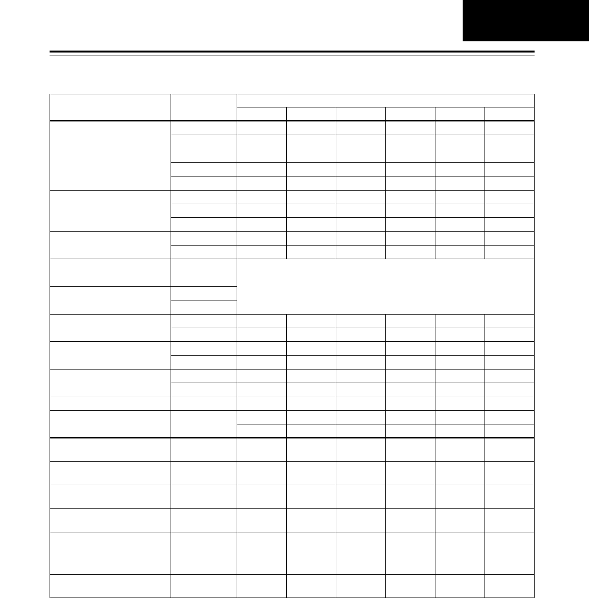
39
Function menus
Allocating the function keys
F1 F2 F3 F4 F5 F6
Menu (6 types) Menu hierarchy Items allocated to function keys
HOME 1st OUTPUT TC/CTL TC CLR R INH
2nd (SHIFT) PREROL OUTREF CAPSTN VARMEM
VIDEO 1st VID IN INT SG WFM UP CON DW CON
2nd (SHIFT)
3rd (F+SHIFT)
V LV C LV HUE SUP LV
BR CT R-BR B-BR R-CT B-CT
AUDIO
1st A1 IN A2 IN DIN 12 A3 IN A4 IN DIN 34
2nd (SHIFT) A5 IN A6 IN DIN 56 A7 IN A8 IN DIN 78
3rd (SHIFT) VOLUME RECCUE M MIX
TC 1st TC SRC TCG MD TCG RG RUN MD DF MOD
2nd (SHIFT) SUPER C HPOS C VPOS DISPLY C TYPE TIMER
PF1 1st F1 F1 F1 F1 F1 F1
2nd (SHIFT) F1 F1 F1 F1 F1 F1
PF2 1st F1 F1 F1 F1 F1 F1
2nd (SHIFT) F1 F1 F1 F1 F1 F1
CUE
MULTICUE function
1st PREV NEXT MODE CLR AL CLR
2nd (SHIFT) CARD PAGE ROTATE CU-ROL
DIAG
ERROR LOG function
1st WARN HOURS
2nd (SHIFT) STEP CARD AL CLR
MENU 1st FILE CARD SYSTEM SETUP
2nd (SHIFT) PF1 FT PF1 BK PF2 FT PF2 BK 50P IN 50P OT
ASSEM ASSEM
SYSTEM
SYSTEM MENU (ON SCREEN)
CANCEL RESET SET EXIT
SETUP
SETUP MENU (ON SCREEN)
: PREV ;NEXT CANCEL RESET SET EXIT
FILE
USER FILE BACKUP function
P.LOAD LOAD <SAVE >LOCK EXIT
PF1, PF2
MENU ASSIGN function : PREV ; NEXT CANCEL RESET SET EXIT
CARD
IC CARD function (MENU)
IC CARD function (ERRLOG)
IC CARD function (MULTI CUE)
FORMAT SAVE <LOAD >DELETE LOCK EXIT
50PIN
50-pin ASSIGN function :PREV ;NEXT CANCEL RESET SET EXIT
INSERT A5 A6 A7 A8 TC
V A1A2A3A4CUE
No factory settings (any items can be allocated to any keys).
Warning mark
When a warning occurs in this VTR, the warning mark (W) blinks. If the DIAG button is then pressed, the corresponding warning message is
displayed on the screen. ( See DIAG screen.)
GENERAL
DESCRIPTION

40
Function menus
Toggle:
Each time a function button is pressed, the setting is
changed or entered.
F itoggle*:
When a function button is pressed while the F button
is held down, the setting can be changed or entered
each time.
Toggle iADJ:
When a function button is pressed, the setting is
highlighted, and the status in which the setting can be
changed is established.
The ADJUST dial is used to change the setting.
When the same function button is pressed again and
the highlighting is released, the setting is entered.
Press:
When a function button is pressed, the setting can be
changed while the button is held down or at the
instant when it is pressed. When the function button
is released, the original setting is restored.
F ipress*:
When a function button is pressed while the F button
is held down, the setting can be changed while the
button is held down or at the instant when it is
pressed. When the function button is released, the
original setting is restored.
* When only the function button is pressed, message
display “Press i” etc. blinks.
F5F
How to switch the settings
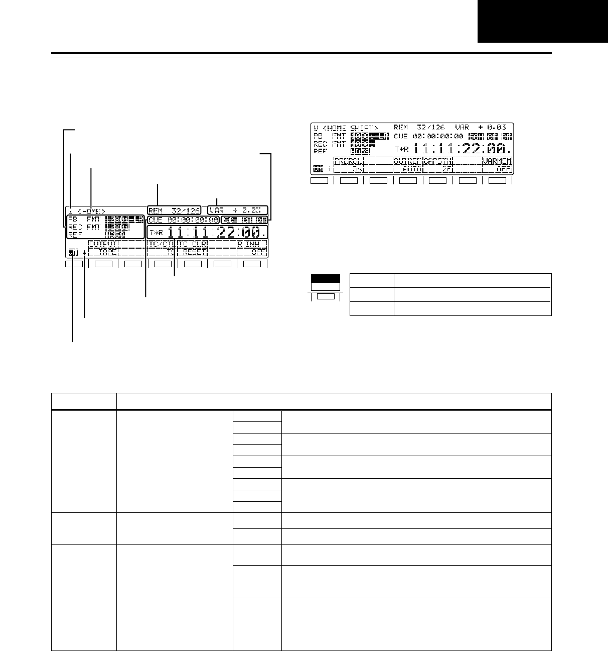
41
Function menus
<HOME>
F1
SHIFT
F2 F3 F4 F5 F6
Status display 1
Status display 2
Warning mark
Name of menu displayed
Remaining tape/total tape
Time counter
Cue time
Back menu indicator
Variable memory mode indicator
Operation mode/speed
F1
SHIFT
F2 F3 F4 F5 F6
The most basic settings for recording, playback and
TC operations are set on this menu screen.
VTR
PB FMT Playback format
This displays the format used
for playback.
1080i LP
720p LP
1080i SP
720p SP
422
420p
411
DV
DVCAM
Description of settings
These settings indicate the DVCPRO HD-LP recording and playback
mode.
REC FMT*1Recording format
This displays the format used
for recording.
1080i
720p
The tape is recorded using the 1080i format.
The tape is recorded using the 720p format.
TM INFO*2Tape management
information
This displays the frame rate
(shooting speed) information
which is recorded on a tape
shot by a variable frame rate
camera. INVALID The tape management information is invalid.
<Note>
In some cases, the tape management information may be erroneously
overwritten by insert editing or tape dubbing, and it may not be possible to
perform editing properly.
- - - A cassette tape has not been inserted.
24P
24PA
25P
These settings indicate the recorded frame rate.
These settings indicate the DVCPRO HD-SP playback mode.
These settings indicate the DVCPRO (50 Mbps format) playback mode.
These settings indicate the DVCPRO (25 Mbps format), DV and DVCAM
playback modes.
Status display 1
*1: This status is not displayed when the 23/24 Hz or 25 Hz (HD or SD) mode has been selected as the system menu item
No.25 (SYSTEM FREQ) setting.
*2: This status is not displayed when the 59/60 Hz or 50 Hz mode has been selected as the system menu item No.25
(SYSTEM FREQ) setting.
HOW TO SWITCH
THE SETTINGS
SYSTEM
23/24
F1
25 (SD)
23/24 The 23/24 Hz mode is selected.
25 (HD) The 25 (HD) Hz mode is selected.
The 25 (SD) Hz mode is selected.
System frequency display during 24 Hz, 25 Hz (HD and SD)
modes
When 24 Hz mode or 25 Hz (HD or SD) mode has been selected
for the system menu item No. 25 (SYSTEM FREQ), the selected
system frequency contents are displayed for the F1 function button,
making it possible to check the currently selected system frequency
mode.
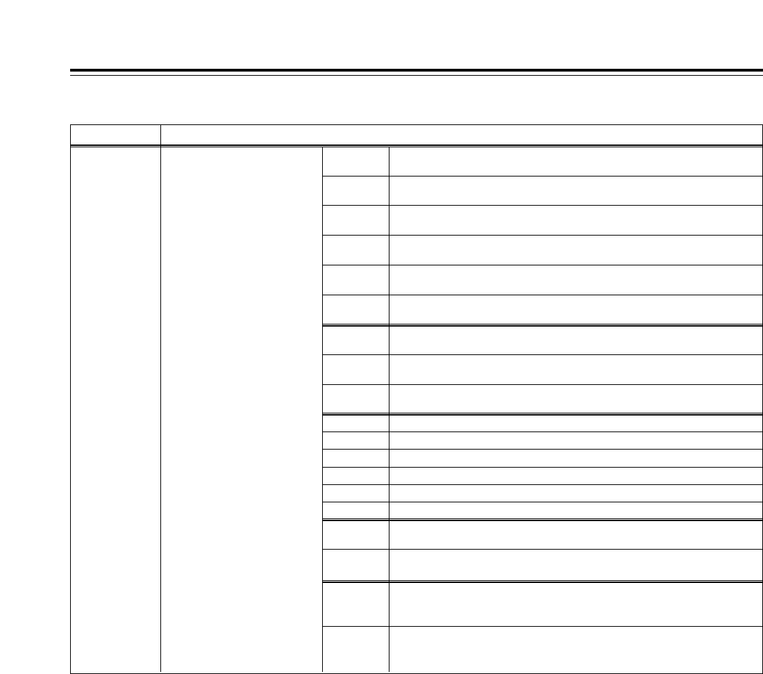
42
VTR Description of settings
Status display 1 (continued)
REF Output reference
This displays the output
reference status.
HD25
HD50
The HD REF input signal has been selected as the reference. The frame
frequency is 25 Hz.
HD23 The HD REF input signal has been selected as the reference. The frame
frequency is 23.98 Hz.
The HD REF input signal has been selected as the reference. The field
frequency is 50 Hz.
HD59 The HD REF input signal has been selected as the reference. The field
frequency is 59.94 Hz.
HD60 The HD REF input signal has been selected as the reference. The field
frequency is 60 Hz.
IN50 The HD serial input signal has been selected as the reference. The field
frequency is 50 Hz.
HD24 The HD REF input signal has been selected as the reference. The frame
frequency is 24 Hz.
IN59 The HD serial input signal has been selected as the reference. The field
frequency is 59.94 Hz.
IN60 The HD serial input signal has been selected as the reference. The field
frequency is 60 Hz.
INT23
The signal (23.98 Hz) from the internal generator has been selected as the reference.
INT25
The signal (25 Hz) from the internal generator has been selected as the reference.
INT50
The signal (50 Hz) from the internal generator has been selected as the reference.
INT59
The signal (59.94 Hz) from the internal generator has been selected as the reference.
INT60
The signal (60 Hz) from the internal generator has been selected as the reference.
NTSC59 The SD REF input signal has been selected as the reference. The field
frequency is 59.94 Hz.
PAL50 The SD REF input signal has been selected as the reference. The field
frequency is 50 Hz.
INT59N The SD REF signal has been selected by the OUT REF setting. Since the
SD REF signal is not input, the signal (59.94 Hz) from the internal
generator is selected as the reference.
INT50P The SD REF input signal has been selected by the OUT REF setting.
Since the SD REF signal is not input, the signal (50 Hz) from the internal
generator is selected as the reference.
INT24
The signal (24 Hz) from the internal generator has been selected as the reference.
Function menus
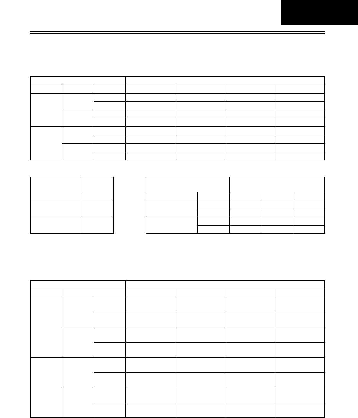
43
Function menus
<HOME>
Playback reference signal (OutRef) specifications for tape playback
Input signal provided (“Yes”)/not provided (“No”)
HD_REF_IN
Yes
No
SD_REF_IN
Yes
No
Yes
No
INPUT
Yes
No
Yes
No
Yes
No
Yes
No
AUTO EXT_HD_REF EXT_SD_REF INPUT
HD_REF_IN HD_REF_IN SD_REF_IN INPUT
HD_REF_IN HD_REF_IN SD_REF_IN Internal HD
HD_REF_IN HD_REF_IN Internal SD INPUT
HD_REF_IN HD_REF_IN Internal SD Internal HD
SD_REF_IN Internal HD SD_REF_IN INPUT
SD_REF_IN Internal HD SD_REF_IN Internal HD
INPUT Internal HD Internal SD INPUT
Internal HD Internal HD Internal SD Internal HD
OUTREF setting (menu 031)
Internal HD: HD playback reference, 74MHzCLK operates at FreeRun setting.
Internal SD: SD playback reference, 4fscCLK operates at FreeRun setting.
HOME
59.94 Hz/60 Hz operation specifications for tape playback
Input signal provided (“Yes”)/not provided (“No”)
HD_REF_IN
Yes
No
SD_REF_IN
Yes
No
Yes
No
INPUT
Yes
No
Yes
No
Yes
No
Yes
No
AUTO EXT_HD_REF EXT_SD_REF INPUT
Complies with HD
REF IN frequency.
Complies with HD
REF IN frequency. 59.94Hz Complies with INPUT
frequency.
Complies with HD
REF IN frequency.
Complies with HD
REF IN frequency.
Complies with HD
REF IN frequency.
59.94Hz
59.94Hz
Complies with INPUT
frequency.
Complies with Menu
030 setting.
Complies with HD
REF IN frequency.
Complies with HD
REF IN frequency.
Complies with HD
REF IN frequency.
Complies with Menu
030 setting.
Complies with Menu
030 setting.
Complies with Menu
030 setting.
Complies with Menu
030 setting.
59.94Hz
59.94Hz
59.94Hz
59.94Hz
59.94Hz
59.94Hz
59.94Hz
Complies with Menu
030 setting.
Complies with INPUT
frequency.
Complies with Menu
030 setting.
Complies with INPUT
frequency.
Complies with Menu
030 setting.
Complies with INPUT
frequency.
Complies with Menu
030 setting.
OUTREF setting (menu 031)
Menu 030: HD FREQUENCY 59.94/60 selection
<Note>
Operation cannot be performed in the 60 Hz mode during SD tape playback.
Input signal provided
(“Yes”)/not provided (“No”)
HD_REF_IN
Yes
No
HD_REF_IN
Internal HD
23.98/24Hz, 25 Hz (HD) mode
Input signal provided (“Yes”)/
not provided (“No”) OUT REF setting (Menu 031)
HD_REF_IN
Yes
No
SD_REF_IN
Yes
No
Yes
No
AUTO
HD_REF_IN
HD_REF_IN
SD_REF_IN
Internal HD
HD_REF
HD_REF_IN
HD_REF_IN
Internal HD
Internal HD
SD_REF
SD_REF_IN
Internal SD
SD_REF_IN
Internal SD
25 Hz (SD) mode
59.94 Hz/60 Hz, 50 Hz mode
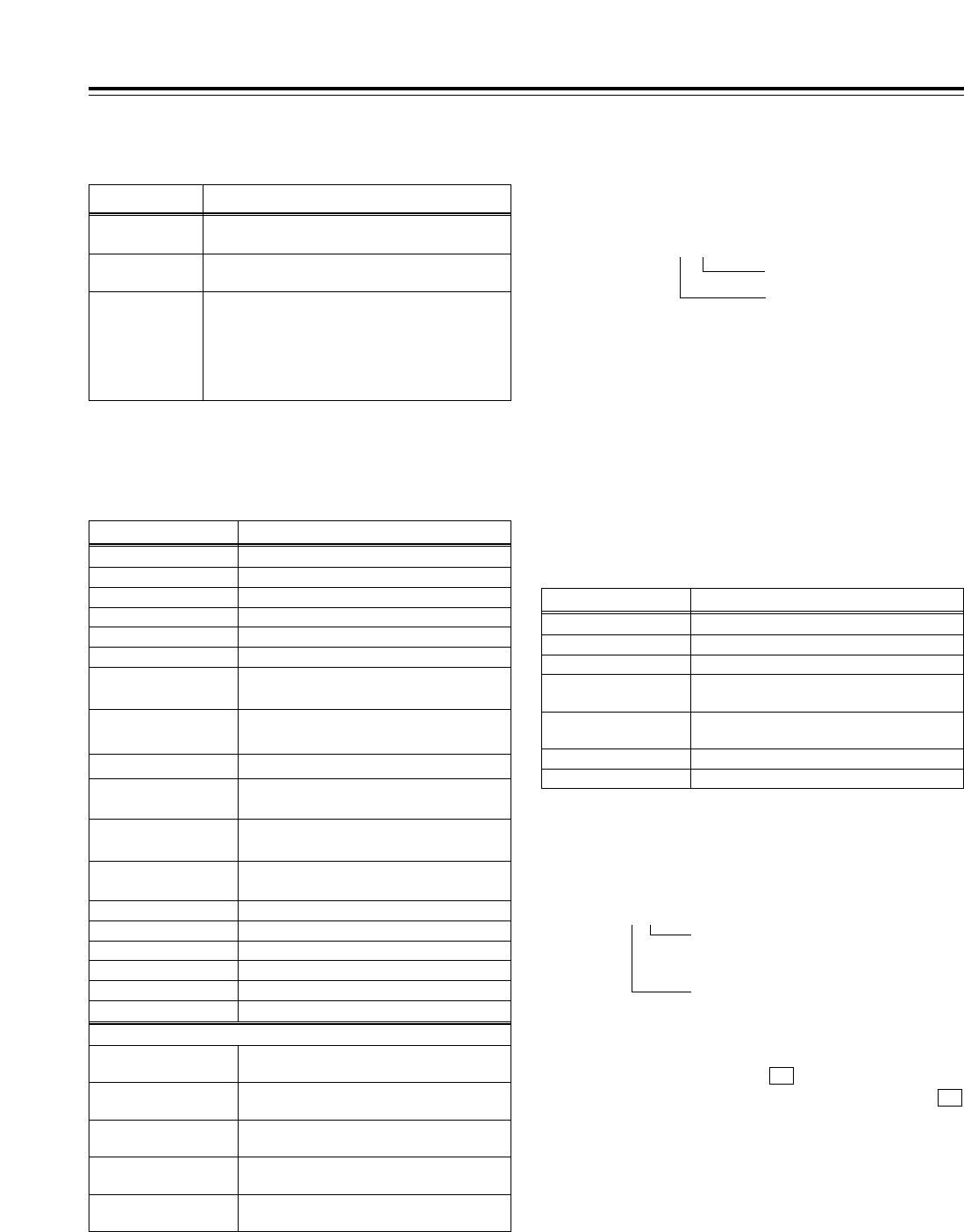
44
Function menus
<HOME>
Operation mode (speed) display
This indicates the current operation mode (including
the speed display).
Display
EJECT
Operation mode
Eject mode
STANDBY OFF Standby OFF mode
T.RELEASE Tension release mode
STOP Stop mode
PREROLL Preroll mode
PLAY Playback mode
PLAY iSpecial playback (playback phase
adjustment) mode (FWD direction)
PLAY jSpecial playback (playback phase
adjustment) mode (REV direction)
REC Recording mode
JOG
REV/STILL/FWD Jog mode
VAR (speed)
[j4.9 to i4.9] Variable mode
SHTL (speed)
[j32.0 to i32.0]Shuttle mode
FF Fast forwarding mode
REW Rewinding mode
EDIT Editing mode
AUTO EDIT Automatic editing mode
PREVIEW Preview mode
When function F6 (VARMEM) on <HOME SHIFT> is “ON”
DSPD (speed)
[j1.0 to i2.0]Initial speed setting of variable memory
DSMP (speed)
[j1.0 to i2.0]Playback speed memory mode of variable
memory
DPLY (speed)
[j1.0 to i2.0]Playback mode of variable memory
DPRV (speed)
[j1.0 to i2.0]Preview mode of variable memory editing
DEDT (speed)
[j1.0 to i2.0]
Execution mode of variable memory editing
REVIEW Review mode
Indicator
SCH This lights when the SCH phase of the SDREF
signal is within the prescribed range.
Description of setting
CF This lights when color framing is locked.
DF This lights during recording or playback in the
drop frame mode.
<Note>
If the time code data could not be read properly
(“T¢R” is displayed), the display of the previous
status is held.
Remaining tape/total tape display
The lengths of the remaining tape and total tape of the
inserted cassette are displayed in increments of minutes.
REM 10/ 92
Cue time display
This displays the currently registered cue time. (For
details on the cue time operation, refer to “Cue point
registration, preroll and cue-up.”)
Cue time operations can be performed on the HOME
screen only.
Status display 2
<Note>
Slight errors may occur. The remaining tape value
blinks when less than 3 minutes of the tape remain.
(10 minutes remaining on a 92-minute tape)
Example:
Total tape
Remaining tape
Time counter displays
Display
CTL
Description
CTL counter data
TCG Time code data of time code generator
UBG User’s bit data of time code generator
tcg When the time code data of time code
generator is preset
ubg When the user’s bit data of time code
generator is preset
TCR/T¢RTime code data of time code reader
UBR/U¢RUser’s bit data of time code reader
If the time code data or user’s bit data could not be
read out properly, “T¢R” or “U¢R” is displayed. If the
CTL signal is present, the time code data is
supplemented by CTL.
Field mark
[1st field: “ ”/2nd field: “.”]
(This does not appear when the i0.3kor
j0.3kspeed is exceeded.)
Drop frame mark (59/60 Hz mode only)
[Non-drop frame mode: “:”/drop frame
mode: “.”]
Variable memory mode indicator
This is displayed when the (VARMEM) function
button on <HOME SHIFT> is set to “ON.” While
is lighted, variable memory operations can be
performed at any time.
(For details, refer to “Variable memory function.”)
VM
F6
TCR 00:00:00:00.

45
<HOME>
Registering TCG values
1.
2.
3.
Selecting the values
Press the TC/CTL button to select TC.
Press the button. The selected item (cue time
or TC) is now highlighted.
Turn the ADJUST dial to select TC.
Again press the button. A single digit is
highlighted, and the mode for inputting numerical
values is established.
<Notes>
• The UBG value and cue time can be registered
in the same way. The CTL value cannot be
registered.
• TC or UB can be registered only when the
internal time code generator has been selected.
T
T
Inputting numbers and letters
Press the to number keys to input
numerical values.
Use the + buttons to input A, B and C, and
the + buttons to input D, E and F.
To move the input digit, turn the ADJUST dial.
To input a minus sign, press the and ]
buttons when the left-most digit is highlighted.
To input a plus sign, press the and ]
buttons when the left-most digit is highlighted or
press the button.
(The display goes blank.)
To clear all the digits to zero, press the and
buttons.
<Notes>
• When the button is tapped while the
button is held down, the display changes in the
following sequence: A >B >C >A >B and
so on. The same applies when D, E and F are
input using and .
• If, when “REV” has been selected as the setup
menu item No.144 (TC INPUT) setting, the
button is released while a letter is being input,
the displayed character will be entered.
• Letters can be input only while a UBG value is
being registered.
• The input of a minus number is possible only
while the cue time is being registered after
“d12h” is selected as the setup menu No.002
(TAPE TIMER) setting and CTL is selected by
the TC/CTL button.
• If “REV” has been selected as the setup menu
item No.144 (TC INPUT) setting, the input
starts from the highest order digit (the display
appears from the far right). However, turning
the ADJUST dial once will restore the NORMAL
input mode.
F3
F
8F
F7
0F
0
TRIMi
F
TRIMj
F
8F
7F
90
Entering the input values
Press the button. The value input is
registered, and the normal display is restored.
<Notes>
• To cancel the registration, press the button.
• If the input value is outside the registration
enable range, the alarm blinks, and
the value cannot be registered until it has been
corrected.
INVALID
C
ENT
Function menus HOME
F3

46
Function menus
<HOME>
Function
button/item Switching
method Corresponding setup
menu item
F1
OUTPUT Toggle No. 140
OUTPUT
Description of setting
For selecting the output signals.
<In the STOP mode>
TAPE: In the STOP mode, the signals played back from the
tape are output.
During recording or editing (*), simultaneous playback
signals are output.
*: Setup menu item No.302 (CONFI EDIT) must be set.
EE:The input signals selected by the setup menu items
No.600 (VIDEO IN SEL) and No.713 (CH1 IN SEL) to
No.724 (D IN SEL 78) settings are output.
Setting
TAPE
EE
F3
TC/CTL*2
Toggle ___ For selecting the time counter display.
TC:The time code value is displayed.
UB: The user’s bit value is displayed.
CTL: The control signal (time data) is displayed.
TC
UB
CTL
F6
R INH F itoggle No. 113
REC INH
Refer to the setup menu.
<Note>
The setting can be changed from OFF to ALL simply by
operating the function button without pressing the F button.
OFF
ALL
PRE
NORM
V/CTL
F4 (SHIFT)
CAPSTN F itoggle No. 109
CAP. LOCK
Refer to the setup menu.2F
4F
8F
F3 (SHIFT)
OUTREF F itoggle No. 031
OUT REF
Refer to the setup menu.AUTO
INPUT
HD_REF
SD_REF
F1 (SHIFT)
PREROL Toggle i
ADJ
No. 000
P-ROLL TIME
Refer to the setup menu.0s --- 5s ---
30s
F6 (SHIFT)
VARMEM*1
Toggle ___ For selecting the variable memory mode.
OFF:The variable memory mode is not used.
ON: The status is established in which variable memory
playback or variable memory editing is enabled.
OFF
ON
F4
TC CLR*1
Press ___ For resetting the time counter display.
If the F4 button is pressed while the control signal (time
data) is displayed on the time counter, it is reset to zero.
RESET
F2
___ ___ ___ ______
F5
___ ___ ___ ______
F2 (SHIFT)
___ ___ ___ ______
F5 (SHIFT)
___ ___ ___ ______
*The underlining (__) denotes the factory setting mode.
*1: This item is not displayed when the 23/24 Hz or 25 Hz (HD or SD) mode has been selected as the system menu item No.25 (SYSTEM
FREQ) setting.
*2: CTL cannot be selected when the 23/24 Hz or 25 Hz (HD or SD) mode has been selected as the system menu item No.25 (SYSTEM
FREQ) setting. TC is selected when the power is turned on.
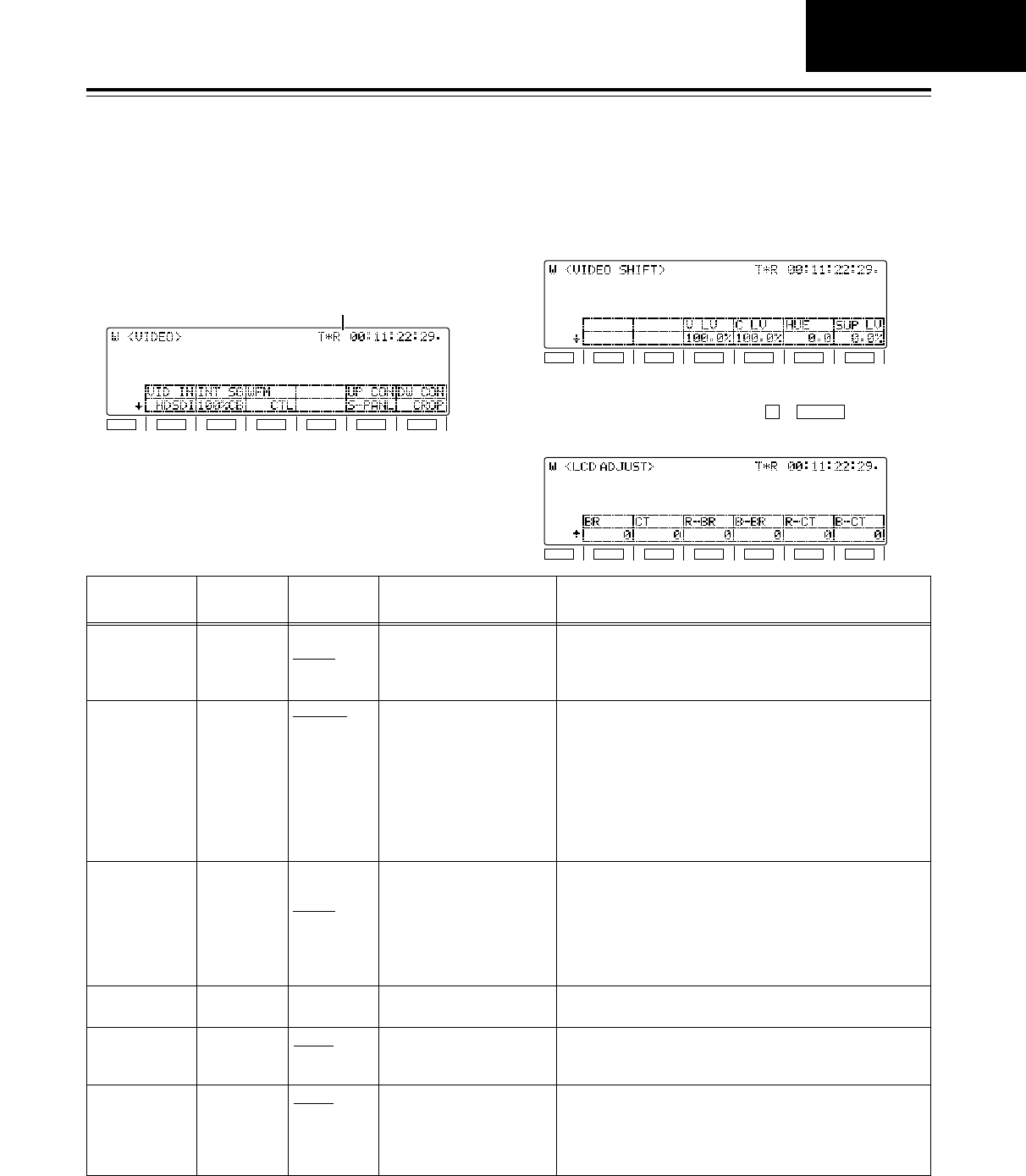
47
Function menus
<VIDEO>
1. Video signal input switching, internal signal
source type changing, and up-converter aspect
ratio conversion
Function
button/item Switching
method Corresponding setup
menu item
F1
VID IN Toggle No. 600
VIDEO IN SEL
Description of setting
Refer to the setup menu.
The SD SDI and SDTI settings will not appear if the optional
boards have not been installed.
Setting
INT SG
HDSDI
SDTI
SDSDI
F5
UP CON Toggle No. 621
UPCONV MODE
Refer to the setup menu.FIT_V
FIT_H
FIT_HV
F2
INT SG Toggle No. 601
VIDEO INT SG
Refer to the setup menu.100%CB
75%CB
SMPTE
ARIB
MB
RAMP
BLACK
PLL
EQ
F6
DW CON Toggle No. 620
DOWNCON MODE
Refer to the setup menu.FIT_V
FIT_H
FIT_HV
14:9
13:9
F3
WFM Toggle No. 00
WFM SEL
Refer to the setup menu.CTL
TC
VIDEO
RF L
RF R
ENV L
ENV R
F4
___ ___ ___ ______
*The underlining (__) denotes the factory setting mode.
F1
SHIFT
F2 F3 F4 F5 F6
Time counter
The basic input/output settings for the video signals
are set, and the level of the HD output signals can
also be adjusted on these menu screens.
VIDEO
2. Video signal output level adjustments
3.
LCD monitor brightness and color adjustments
This display appears when the + buttons are
pressed. Refer to setup menu items No.670 to 675.
SHIFTF
F1
SHIFT
F2 F3 F4 F5 F6
F1
SHIFT
F2 F3 F4 F5 F6

48
Function menus
<VIDEO>
*The underlining (__) denotes the factory setting mode.
Function
button/item Switching
method Corresponding setup
menu item Description of settingSetting
F3 (SHIFT)
Y HD Toggle i
ADJ
No. 653
Y LVL(HD)
Refer to the setup menu.
To return to the UNITY (100.0%) level, use F iPress.
0.0% ---
100.0% ---
141.3%
F4 (SHIFT)
Pb HD Toggle i
ADJ
No. 654
Pb LVL(HD)
Refer to the setup menu.
To return to the UNITY (100.0%) level, use F iPress.
0.0% ---
100.0% ---
141.3%
F5 (SHIFT)
Pr HD Toggle i
ADJ
No. 655
Pr LVL(HD)
Refer to the setup menu.
To return to the UNITY (100.0%) level, use F iPress.
0.0% ---
100.0% ---
141.3%
F6 (SHIFT)
BK HD Toggle i
ADJ
No. 656
BK LVL(HD)
Refer to the setup menu.
To return to the UNITY (0.0%) level, use F iPress.
j10.0% ---
0.0% ---
i10.0%
When “CMPNT” is selected as the setup menu item No.650 (STYLE) setting
When “CMPST” is selected as the setup menu item No.650 (STYLE) setting
F1 (SHIFT)
___ ___ ___ ______
F2 (SHIFT)
___ ___ ___ ______
F1 (SHIFT)
___ ___ ___ ______
F2 (SHIFT)
___ ___ ___ ______
F3 (SHIFT)
V LV Toggle i
ADJ
No. 662
V LEVEL
Refer to the setup menu.
To return to the UNITY (100.0%) level, use F iPress.
0.0% ---
100.0% ---
200.0%
F4 (SHIFT)
C LV Toggle i
ADJ
No. 663
C LEVEL
Refer to the setup menu.
To return to the UNITY (100.0%) level, use F iPress.
0.0% ---
100.0% ---
141.3%
F5 (SHIFT)
HUE Toggle i
ADJ
No. 664
HUE
Refer to the setup menu.
To return to the UNITY (0.0) level, use F iPress.
j31.0 ---
0.0 ---
i31.0
F6 (SHIFT)
SUP LV Toggle i
ADJ
No. 665
SETUP LVL
Refer to the setup menu.
To return to the UNITY (0.0%) level, use F iPress.
j10.0% ---
0.0% ---
i10.0%
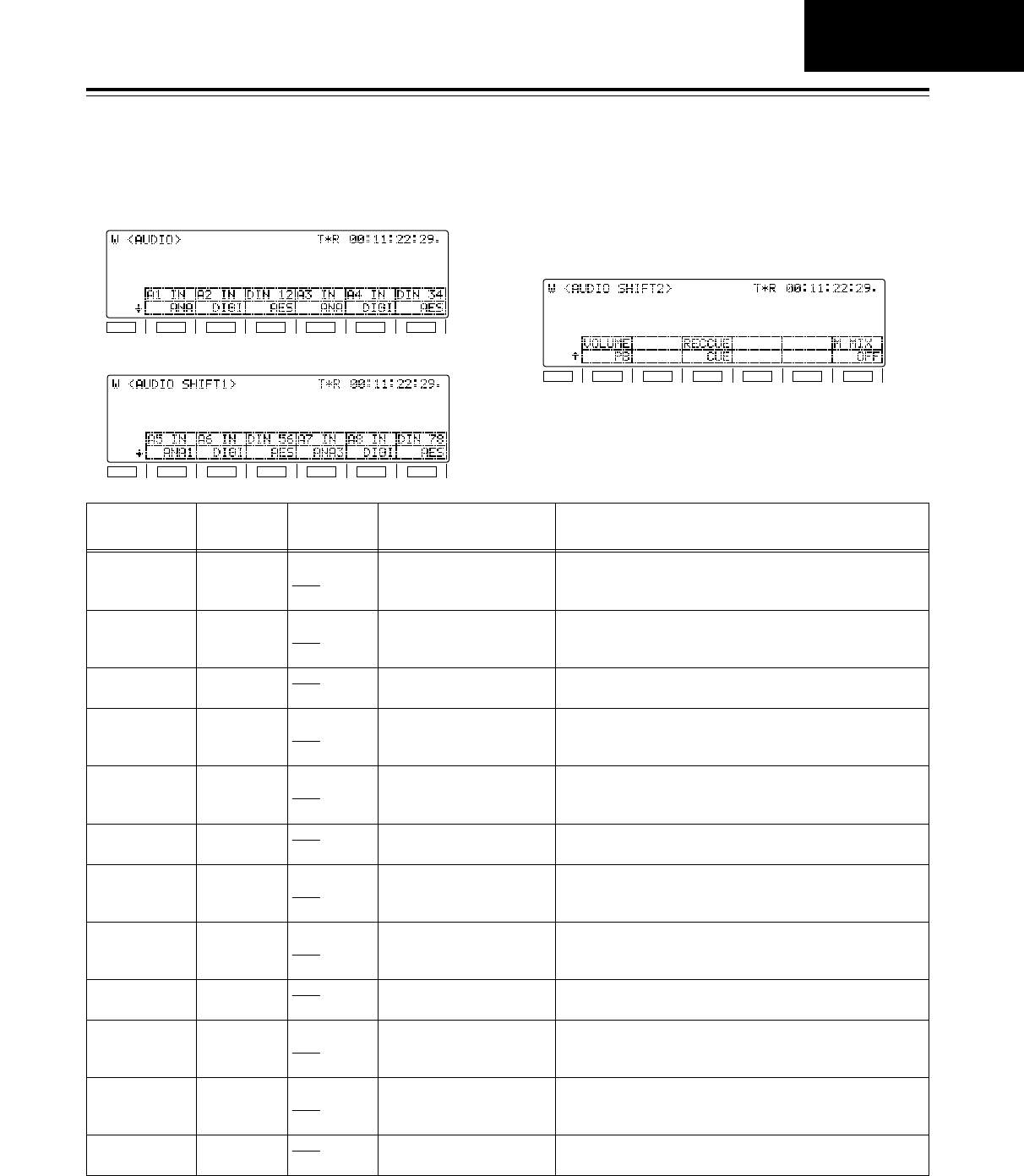
49
Function menus
<AUDIO>
*The underlining (__) denotes the factory setting mode.
F1
SHIFT
F2 F3 F4 F5 F6
F1
SHIFT
F2 F3 F4 F5 F6
F1
SHIFT
F2 F3 F4 F5 F6
The basic input/output settings for the audio signals
are set on these menu screens.
1. Audio signal input selection (CH1jCH4)
2. Audio signal input selection (CH5-CH8)
3. Audio volume control switching, CUE audio
recording signal selection, and audio monitor
mix switching
Function
button/item Setting Corresponding setup
menu item
F1
A1 IN Toggle No. 713
CH1 IN SEL
Description of setting
Refer to the setup menu.
Setting
INT SG
DIGI
ANA
F2
A2 IN Toggle No. 714
CH2 IN SEL
Refer to the setup menu.INT SG
DIGI
ANA
F4
A3 IN Toggle No. 715
CH3 IN SEL
Refer to the setup menu.INT SG
DIGI
ANA
F5
A4 IN Toggle No. 716
CH4 IN SEL
Refer to the setup menu.INT SG
DIGI
ANA
F3
DIN 12 Toggle No. 721
D IN SEL 12
Refer to the setup menu.AES
SDI
F6
DIN 34 Toggle No. 722
D IN SEL 34
Refer to the setup menu.AES
SDI
F1 (SHIFT1)
A5 IN Toggle No. 717
CH5 IN SEL
Refer to the setup menu.INT SG
DIGI
ANA1
F2 (SHIFT1)
A6 IN Toggle No. 718
CH6 IN SEL
Refer to the setup menu.INT SG
DIGI
ANA2
F3 (SHIFT1)
DIN 56 Toggle No. 723
D IN SEL 56
Refer to the setup menu.AES
SDI
F4 (SHIFT1)
A7 IN Toggle No. 719
CH7 IN SEL
Refer to the setup menu.INT SG
DIGI
ANA3
F5 (SHIFT1)
A8 IN Toggle No. 720
CH8 IN SEL
Refer to the setup menu.INT SG
DIGI
ANA4
F6 (SHIFT1)
DIN 78 Toggle No. 724
D IN SEL 78
Refer to the setup menu.AES
SDI
AUDIO
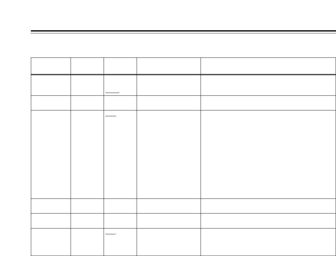
50
Function menus
<AUDIO>
Function
button/item Switching
method Corresponding setup
menu item Description of settingSetting
F3 (SHIFT2)
RECCUE Toggle No. 733
REC CUE
Refer to the setup menu.CUE
CH1
CH2
CH3
CH4
CH5
CH6
CH7
CH8
CH1i2
CH3i4
CH5i6
CH7i8
CH1j8
F1 (SHIFT2)
VOLUME Toggle No. 141
VOLUME
Refer to the setup menu.
For switching what is to be controlled by the audio volume
controls. (The levels of all the CH1jCH8 channels are controlled.)
REC
PB
AUTO
F5 (SHIFT2)
___ ___ ___ ______
F4 (SHIFT2)
___ ___ ___ ______
F2 (SHIFT2)
___ ___ ___ ______
F6 (SHIFT2)
M MIX Toggle No. 737
MONI MIX
Refer to the setup menu.OFF
L
R
L/R
*The underlining (__) denotes the factory setting mode.
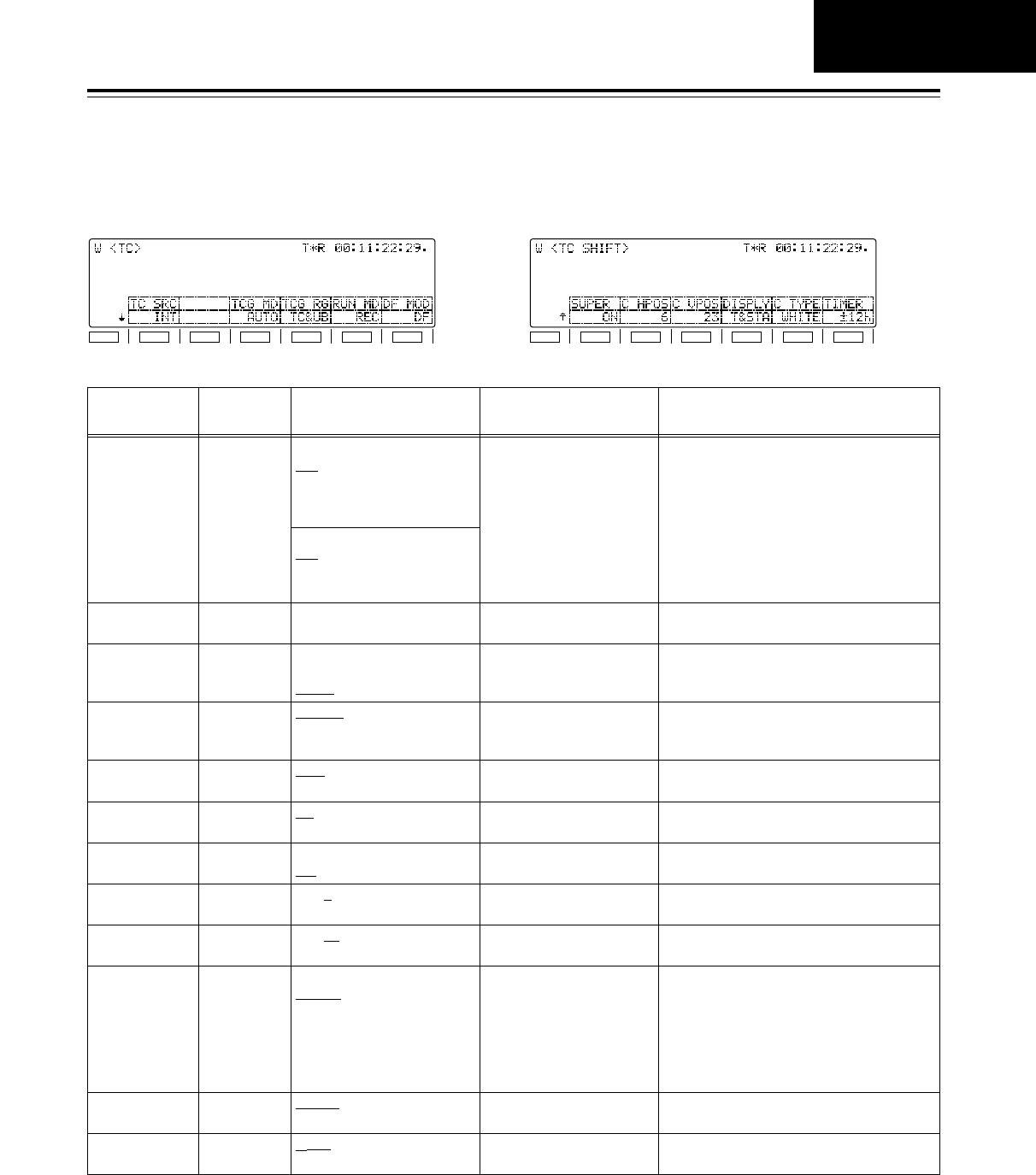
d12h
24h
51
Function menus
<TC>
The TC-related settings are performed on these menu
screens.Whether the TC is to be superimposed onto
the display can also be set on this screen.
Function
button/item Switching
method Corresponding setup
menu item
F1
TC SRC Toggle No. 507
TC SOURCE
Description of setting
Refer to the setup menu.
Setting
When HD SDI, INT SG or SDTI is selected:
INT
EXT_L
SLTC
SVITC
When SD SDI is selected:
INT
EXT_L
VITC
F5
RUN MD Toggle No. 504
RUN MODE
Refer to the setup menu.REC
FREE
F6
DF MOD F itoggle No. 511
DF MODE
Refer to the setup menu.DF
NDF
F1 (SHIFT)
SUPER Toggle No. 005
SUPER
Refer to the setup menu.OFF
ON
F2 (SHIFT)
C HPOS Toggle i
ADJ
No. 007
CHARA H-POS
Refer to the setup menu.0 --- 6 --- 37
F3 (SHIFT)
C VPOS Toggle i
ADJ
No. 008
CHARA V-POS
Refer to the setup menu.0 --- 23 --- 32
F5 (SHIFT)
C TYPE Toggle No. 009
CHARA TYPE
Refer to the setup menu.WHITE
W/OUT
F6 (SHIFT)
TIMER Toggle No. 002
TAPE TIMER
Refer to the setup menu.
F3
TCG MD Toggle No. 503
TCG MODE
Refer to the setup menu.REGEN
PRE
AUTO
F4
TCG RG Toggle No. 505
TCG REGEN
Refer to the setup menu.TC&UB
TC
UB
F4 (SHIFT)
DISPLY Toggle No. 006
DISPLAY SEL
Refer to the setup menu.TIME
T&STA
T&S&M
T&RT
T&YMD
T&MDY
T&DMY
F2
___ ___ ___ ______
*The underlining (__) denotes the factory setting mode.
F1
SHIFT
F2 F3 F4 F5 F6
F1
SHIFT
F2 F3 F4 F5 F6
TC
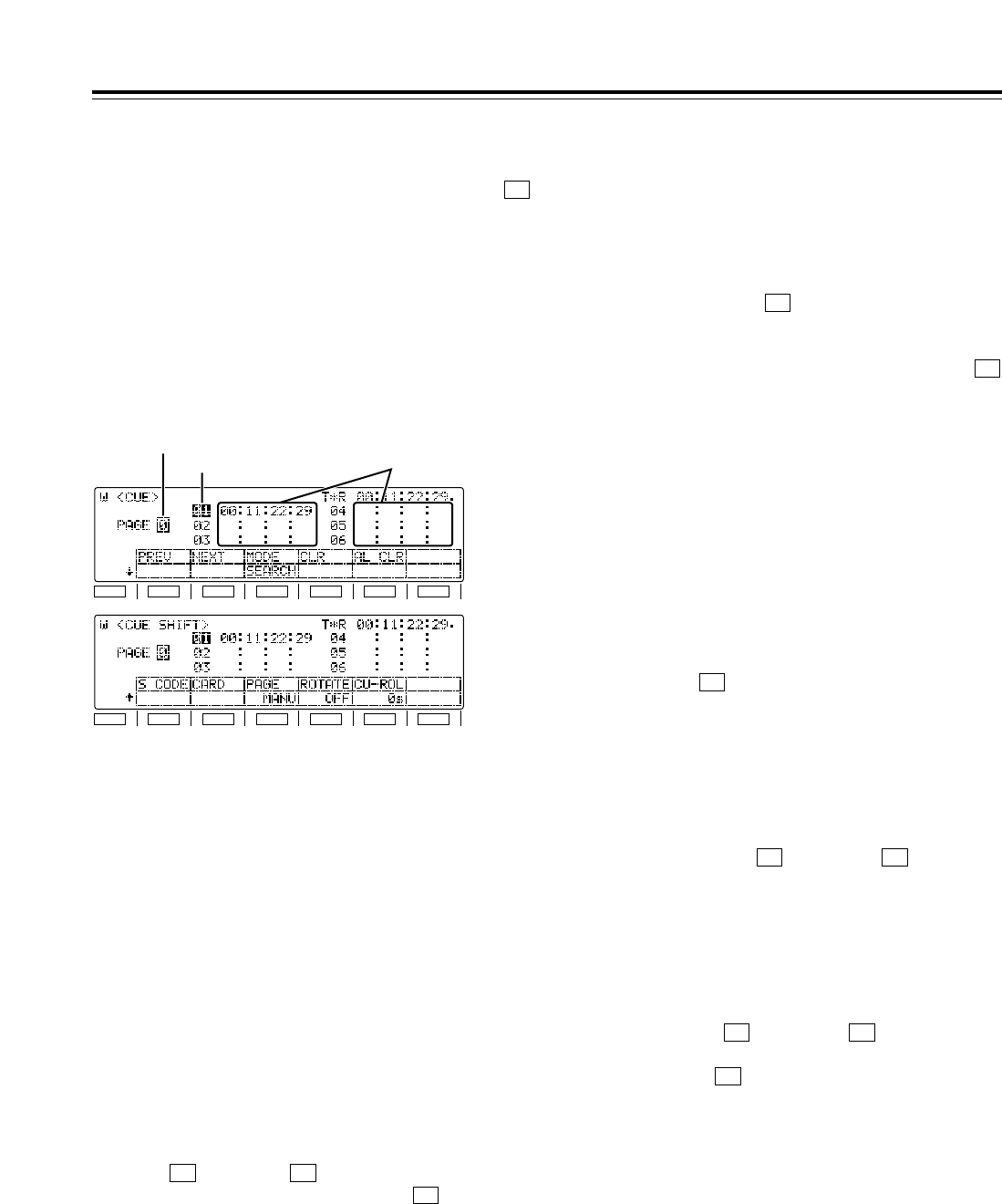
52
Function menus
<CUE>
Moving to registered points
The highlighting on the registered point display area is
moved by turning the ADJUST dial. It is moved in the
ascending order of points when the dial is turned
clockwise and in the descending order of points when
it is turned counterclockwise. When “AUTO” has
been selected as the (PAGE) setting on the
<CUE SHIFT> menu, the highlighting can be moved
also to the previous or next page.
• Depending on the setting selected for
(ROTATE) on the <CUE SHIFT> menu, the
following applies to moving the highlighting in the
ascending order of points.
When “OFF” is set:
The highlighting cannot be moved from page 9 to
page 0.
When “ON” is set:
The highlighting can be moved from page 9 to page 0.
•
In moving in the descending order of points, the
highlighting cannot be moved from page 0 to page 9.
Search point and registered point
operations
Each time the (MODE) button of the <CUE>
menu is pressed, the search mode and cue point
registration mode are switched alternately. Perform
the search point or registered point operations in the
respective mode.
• When the power is turned on, the search point or
registered point, whichever was established when
the power was last turned off, is established.
• When the setting for (PAGE) or (ROTATE)
on the <CUE SHIFT> menu has been changed,
“01” (page 0/point no.1) is set for both the search
and registered points.
Cue point registration mode
It is possible to register points to which the tape is to
be prerolled. When the display page has been
changed using the (PREV) or (NEXT) button
on the <CUE> menu, the following applies depending
on the setting for (PAGE) on the <CUE SHIFT>
menu.
When “MANU” is set:
Both the search and registered points move to the top
of the changed page.
When “AUTO” is set:
Only the registered point moves to the top of the
changed page; the search point does not move.
F3
F2F1
F4F3
F3
F4
F3
A maximum of 60 cue points can be set on these menu
screens. When “AUTO” has been selected as the
(PAGE) setting on the AUTO PAGE mode <CUE SHIFT>
menu, up to 10 pages of cue points with 6 cue points on
each page can be managed on a page-by-page basis.
The 60 cue points are indicated using the page number
display and registered point display areas.
<Note>
Cue points cannot be registered, prerolled, etc. if a
setting other than “ENA” has been selected as the setup
menu item No.001 (LOCAL ENA) setting in the REMOTE
mode.
F3
F1
SHIFT
F2 F3 F4 F5 F6
Page number display area
Registered point display area
Cue point data display areas
Page number display area
The page number from 0 to 9 is indicated here.
Registered point display area
On each page, six cue point data managed by
registered point numbers are displayed. A point
whose registered point number is highlighted is
targeted for registration and search.
Shown below is the correlation between the page
numbers and registered point numbers.
Page no. Registered points Page no. Registered points
0 01–06 5 51–56
1 11–16 6 61–66
2 21–26 7 71–76
3 31–36 8 81–86
4 41–46 9 91–96
Page operations
Pages can be scrolled in the forward or reverse direction
using the [F1] (PREV) or [F2] (NEXT) function buttons.
•
Depending on the setting selected for [F4] (ROTATE)
on the <CUE SHIFT> menu, the following applies to
scrolling pages in the forward direction.
When “OFF” is set:
Page 0 cannot be scrolled forward from page 9.
When “ON” is set:
Page 0 can be scrolled forward from page 9.
•
In scrolling pages in the reverse direction, page 9
cannot be scrolled in reverse from page 0.
F1
SHIFT
F2 F3 F4 F5 F6
F4
F1 F2

53
Search mode
The desired search point can be selected, and the
tape can be prerolled to that point.
When the display page has been changed using the
[(PREV) or (NEXT) button on the <CUE>
menu, the following applies depending on the setting
for (PAGE) on the <CUE SHIFT> menu.
When “MANU” is set:
Both the search and registered points move to the top
of the changed page.
When “AUTO” is set:
Only the search point moves to the top of the changed
page; the registered point does not move.
Cue point registration
Turn the ADJUST dial to highlight the point which is to
be registered. When the button is pressed, the
current tape position is registered as the cue point.
The following applies depending on the setting for
(PAGE) on the <CUE SHIFT> menu.
When “MANU” is set:
Operations are performed on the selected page.
Press the button to register the points in
succession (CUE¢1 >CUE¢2 >... >CUE¢6) on
the selected page. (Any points already registered will
be overwritten.)
The registration is automatically terminated when
CUE¢6 is registered on the page. (*1)
A change must be made to the points to be registered
if more cue points are to be registered. Check that
the cue point registration mode is established, change
the page, and change the points to be registered. In
this case, the search point will also move
automatically to the top (CUE¢1) of the changed
page.
(*1)If “ON” is selected as the ](ROTATE) setting
on the <CUE SHIFT> menu, the registration of the
cue points will rotate on the same page in the
following order: CUE¢1 >CUE¢2 >... >
CUE¢6 >CUE¢1 >CUE¢2 >...
F4
SET
F3
SET
F3
F2F1
When “AUTO” is set:
When a page become full during the cue point
registration process, operation automatically moves to
the next page, and registration continues. When
CUE96 on the last page is reached, registration is
automatically terminated. (*2)
A change must be made to the points to be registered
if more cue points are to be registered. Check that
the cue point registration mode is established, change
the page, and change the points to be registered. In
this case, the search point will not be changed.
(*2)If “ON” is selected as the (ROTATE) setting
on the <CUE SHIFT> menu, the registration of the
cue points will rotate from page 9 (CUE96) to
page 0 (CUE01).
When registering cue points by number
1. Turn the ADJUST dial to highlight the desired
registered point display area.
2. Press the button twice. Only the “10’s” hour
digit of the selected cue point is now highlighted,
and the change enable status is established.
<Note>
When “REV” has been selected as the setup menu
item No.144 (TC INPUT) setting, the input of the
number will start from the higher-order digit (it will
be displayed starting from the far right).
3. Input the number using the number keys.
Movement from one digit to the next is done
automatically after one number has been input.
The desired digit can also be selected by turning
the ADJUST dial.
4. To enter the number, press the button.
When the display screen is switched or when the
button is pressed during the input process, the
change enable status is released, and the setting is
canceled.
C
ENT
T
F4
Function menus
<CUE>
CUE
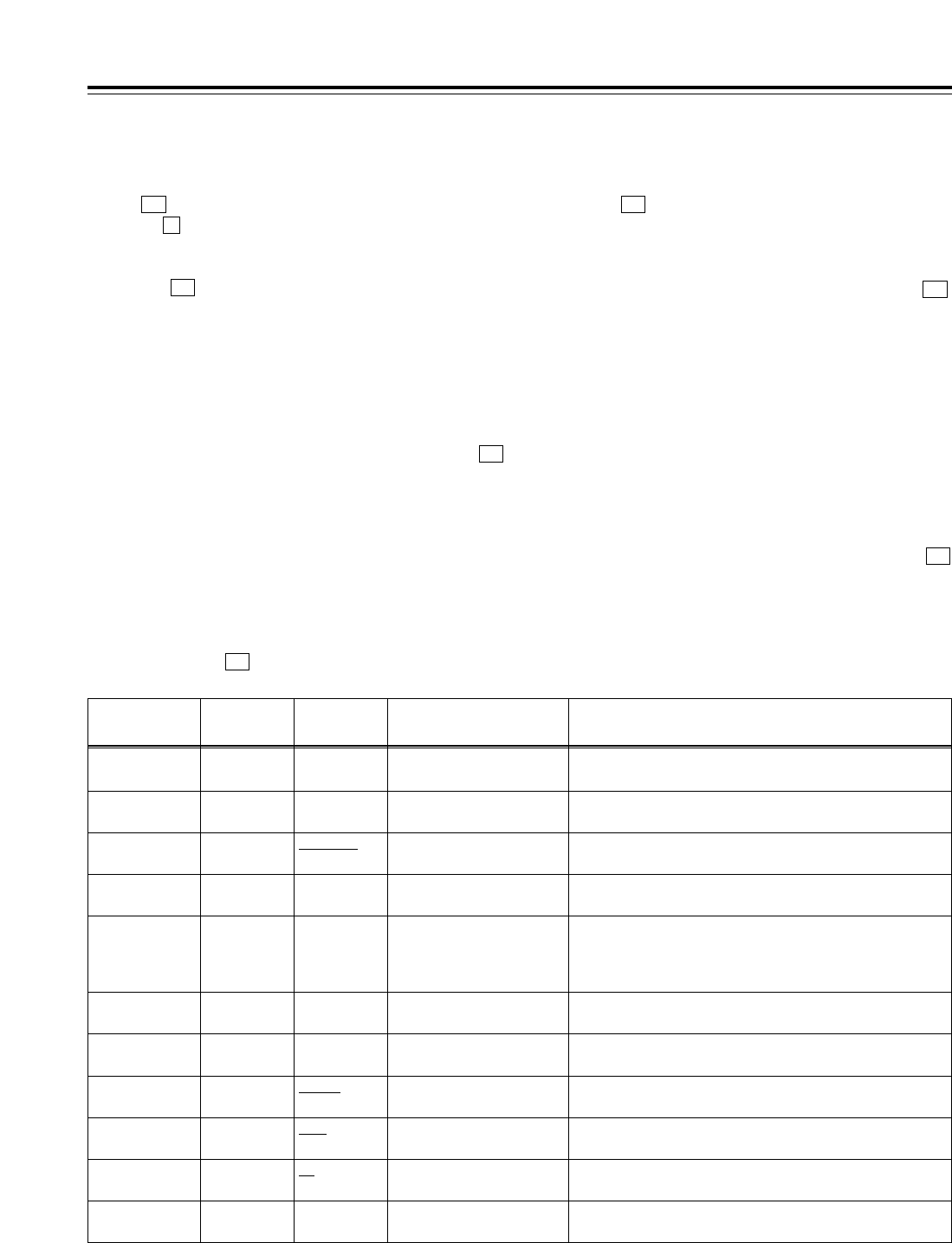
54
Function menus
<CUE>
*The underlining (__) denotes the factory setting mode.
Function
button/item Switching
method Corresponding setup
menu item
F1
PREV Press ___
Description of setting
For multi-cue page forward scrolling.
Setting
___
F2
NEXT Press ___ For multi-cue page reverse scrolling.
___
F4
CLR Press ___ For clearing the currently selected cue data.
ENTRY must be selected as the F3 (MODE) setting.
___
F5
AL CLR FiPress ___ When MANU is selected by SHIFT + F3 (PAGE): All the cue
data on the currently displayed page is cleared.
When AUTO is selected by SHIFT + F3 (PAGE): All the cue
data on all the pages is cleared.
___
F3
MODE Toggle ___ For selecting the search or cue point registration mode.SEARCH
ENTRY
F2 (SHIFT)
CARD FiPress ___ For calling the MULTI CUE file operation menu.
___
F3 (SHIFT)
PAGE Toggle No. 131
PAGE MODE
Refer to the setup menu.MANU
AUTO
F4 (SHIFT)
ROTATE Toggle No. 132
ROTA MODE
Refer to the setup menu.OFF
ON
F5 (SHIFT)
CU-ROL Toggle i
ADJ
No. 011
CU-ROLL TIME
Refer to the setup menu.0s --- 5s ---
15s
F6
___ ___ ___ ______
F6 (SHIFT)
___ ___ ___ ______
$Clearing individual registered points
When the (CLR) button on the <CUE> menu is
pressed, the currently selected cue point data is
cleared.
* The point is cleared only when “ENTRY” (cue point
registration mode) is selected as the setting for ]
(MODE) on the <CUE> menu.
Search operations
Turn the ADJUST dial to highlight the desired
registered point.
When the PREROLL button is pressed, the preroll
operation is initiated. The tape will not be prerolled if
no cue points have been registered.
Since the tape is not prerolled even if the PREROLL
button is pressed when the cue point registration
mode is established, be absolutely sure to check that
the search mode is established.
(The time selected by the <CUE SHIFT> menu [
(CU-ROL) setting, which is different from the normal
preroll time, takes effect as the preroll time in this
mode.)
F5
F3
F4
Clearing registered points
$Clearing all the registered points together
When (AL CLR) on the <CUE> menu is pressed
while the button is held down, all the cue point data
currently selected is cleared. The range of the points
which are cleared is as follows depending on the
setting for (PAGE) on the <CUE SHIFT> menu.
When “MANU” is set:
All the points on the currently selected page are
cleared.
When “AUTO” is set:
All the points on all the pages are cleared.
After clearing, the search and registered points
appear as follows depending on the setting for
(PAGE) on the <CUE SHIFT> menu.
When “MANU” is set:
A return is made to the top (CUE¢1) of the page
concerned.
When “AUTO” is set:
A return is made automatically to the top (CUE01) of
the first page.
* Points are cleared whether “ENTRY” (cue point
registration mode) or “SEARCH” (search mode) is selected
as the setting for [](MODE) on the <CUE> menu.
F3
F3
F3
F
F5
* This item is not displayed when the 23/24 Hz or 25 Hz (HD or
SD) mode has been selected as the system menu item No.25
(SYSTEM FREQ) setting.
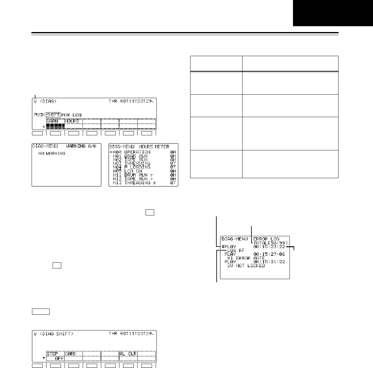
55
Function menus
<DIAG>
Warning display
When a warning occurs in this VTR, the warning mark
(W) blinks at the top left of the screen. If (WARN)
is now pressed, the details of the warning can be
checked out on the LCD monitor.
When more than one warning has occurred, turn the
ADJ dial to scroll through the messages.
Hour-meter display
When (HOURS) is pressed, the hour-meter
information can be checked out on the LCD monitor.
F2
F1
Error log function
The error log mode can be selected by pressing the
button and switching the screen to <DIAG
SHIFT>.
SHIFT
General description
When the following warnings have occurred while the
tape is running, the warning messages, time codes
and operating modes are saved, and a list of this
information can be read out on the LCD monitor. Up
to 99 warnings which have occurred can be saved. If
the storage capacity of 99 warnings is exceeded, the
processing that is conducted as a result is based on
the setup menu item No.015 (AUTO STEP) setting.
F1
SHIFT
F2 F3 F4 F5 F6
F1
SHIFT
F2 F3 F4 F5 F6
Warning mark
The warnings and hour-meter can be checked on
these menu screens. On the SHIFT menu screen,
error log files can be checked, deleted or saved onto
or loaded from IC cards.
Warning messages
which are saved
NO RF
Description
(Refer to page 118 and following.)
A blank section on the tape lasting more
than 1 second has been detected.
(During normal playback)
SV NOT LOCKED The servo has been disengaged for more
than 3 seconds. (During recording,
normal playback or editing)
LOW RF An envelope level which is about 1/3 of
normal or a CTL level which is about 1/6
of normal has been detected for more
than 1 second. (During recording, normal
playback or editing)
HIGH ERROR RATE The error rate has deteriorated, and
correction or compensation has been
applied to the video or audio playback
signals. (During normal playback)
LCD monitor displays
Operation mode display
This indicates the operation mode at the point when
the warning was saved.
Warning display
This indicates the warning message which is saved.
Saved warning status display
This indicates the number of the currently displayed
warning which has been saved and the total number
of warnings which have been saved.
Time code display
This indicates the time code at the point when the
warning was saved.
Cueing up the tape to the warning point
The warning list displayed on the LCD monitor can be
scrolled by turning the ADJ dial. When the warning
occurrence point to be checked is selected and the
PREROLL button is pressed, the tape is cued up to
the position of the time code which has been saved.
Operation mode display
Warning display
Saved warning status display
Time code display
DIAG
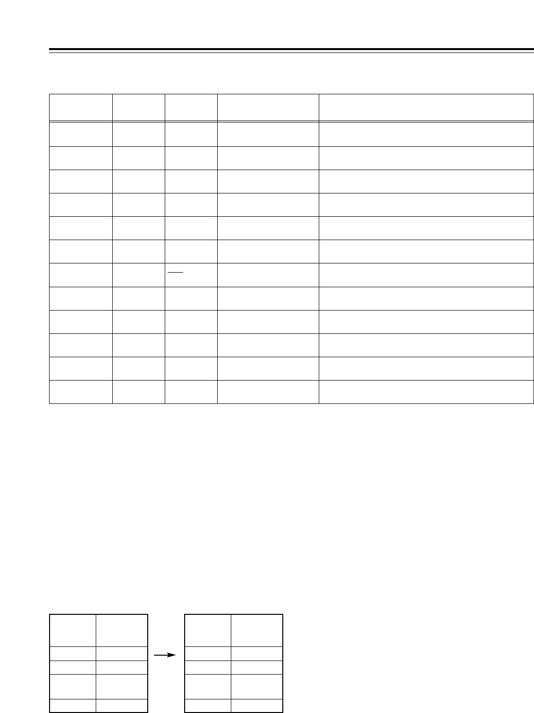
56
Function menus
Function
button/item Switching
method Corresponding setup
menu item
F1
WARN ___ ___
Description of setting
For displaying the warning messages on the LCD monitor.
Setting
___
F2
HOURS ___ ___ For displaying the hour-meter on the LCD monitor.
___
F1 (SHIFT)
STEP Toggle No. 015
AUTO STEP
Refer to the setup menu.OFF
ON
F2 (SHIFT)
CARD FiPress ___ For calling the error log file operation menu.
___
F4 (SHIFT)
___ ___ ___ ______
F5 (SHIFT)
AL CLR FiPress ___ For clearing error log files.
___
F3
___ ___ ___ ______
F4
___ ___ ___ ______
F5
___ ___ ___ ______
F6
___ ___ ___ ______
F3 (SHIFT)
___ ___ ___ ______
F6 (SHIFT)
___ ___ ___ ______
Concerning the setup menu item No.015 (AUTO
STEP) setting (default: OFF)
Up to 99 warning messages can be saved by the error
log function, and this setup menu item determines
what kind of save processing is to be conducted when
this storage capacity is exceeded.
OFF: 99 messages are set as the upper limit, and no
further messages of warnings that occur will be
saved.
ON: 99 messages are saved, and any further
message of a warnings that occurs is saved in
No.99. The warning messages already saved
are each shifted down by one number in
succession.
<DIAG>
No. in which
message is
saved
1/99
2/99
:
:
Saved warning
Warning 1
Warning 2
:
:
99/99 Warning 99
No. in which
message is
saved
1/99
Saved warning
Warning 2
2/99
:
:
Warning 3
:
:
99/99 Warning 100
When up to 99 messages have been saved
and the 100th warning has occurred
Messages saved when ON is selected as the setting
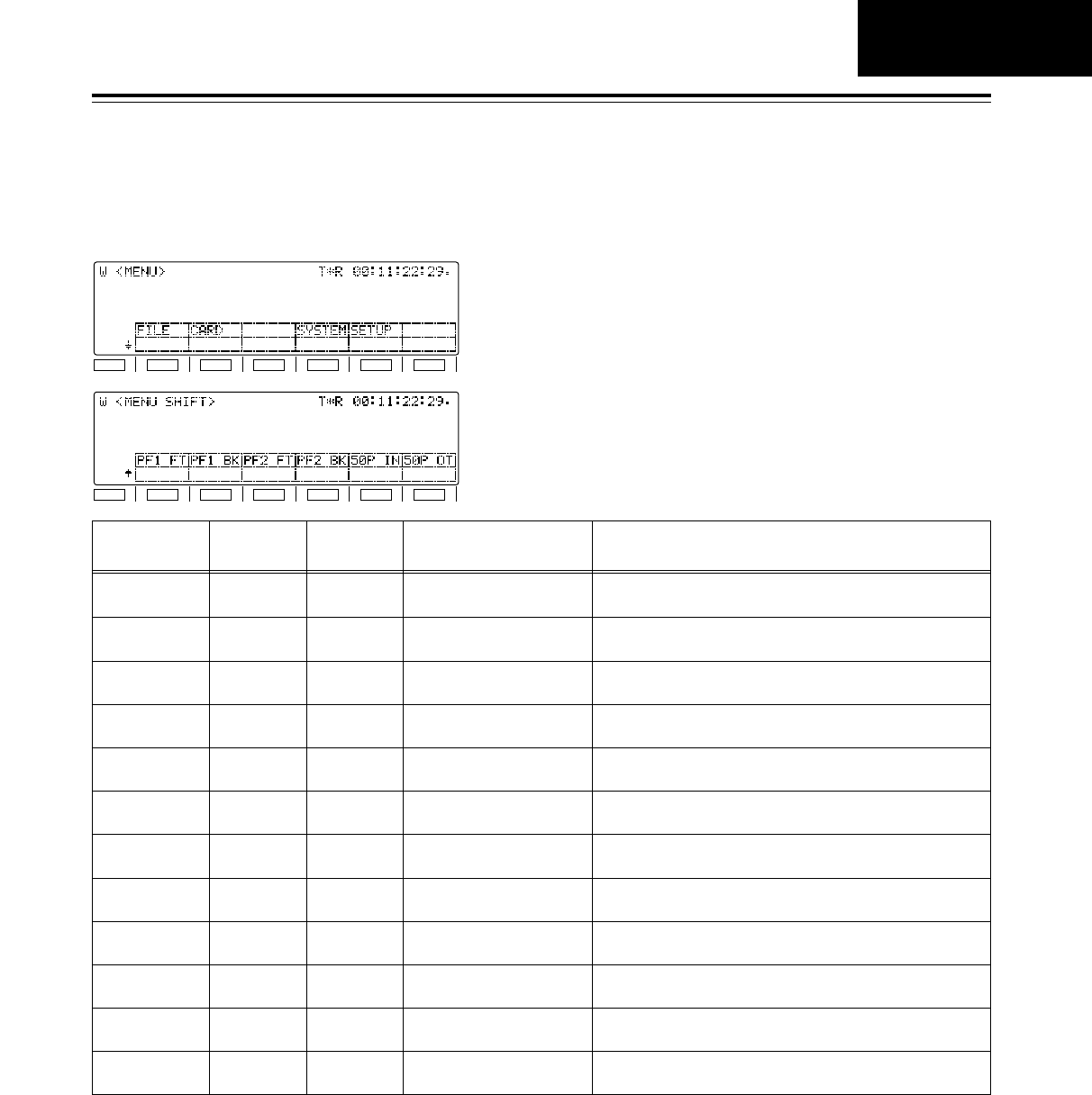
57
Function menus
<MENU>
*The underlining (__) denotes the factory setting mode.
These enable movement to the menu screens for
operations (adjustments, saving data onto or loading it
from the internal memory or IC cards) relating to the
SYSTEM and SETUP menus.
Function
button/item Switching
method Corresponding setup
menu item
F1
FILE FiPress ___
Description of setting
For calling the operation menu for saving the SYSTEM and
SETUP adjustment values (in the internal memory).
Setting
___
F2
CARD FiPress ___ For calling the operation menu for saving the SYSTEM and
SETUP adjustment values (onto the IC card).
___
F4
SYSTEM FiPress ___ For calling the SYSTEM adjustment operation menu.
___
F5
SETUP FiPress ___ For calling the SETUP adjustment operation menu.
___
F1 (SHIFT)
PF1 FT FiPress ___ For calling the PF1/function button assignment operation
menu.
___
F2 (SHIFT)
PF1 BK FiPress ___ For calling the PF1/function button assignment operation
menu.
___
F3 (SHIFT)
PF2 FT FiPress ___ For calling the PF2/function button assignment operation
menu.
___
F4 (SHIFT)
PF2 BK FiPress ___ For calling the PF2/function button assignment operation
menu.
___
F5 (SHIFT)
50P IN FiPress ___ For calling the 50-pin (input pin) assignment operation
menu.
___
F6
___ ___ ___ ______
F3
___ ___ ___ ______
F6 (SHIFT)
50P OT FiPress ___ For calling the 50-pin (output pin) assignment operation
menu.
___
F1
SHIFT
F2 F3 F4 F5 F6
F1
SHIFT
F2 F3 F4 F5 F6
MENU
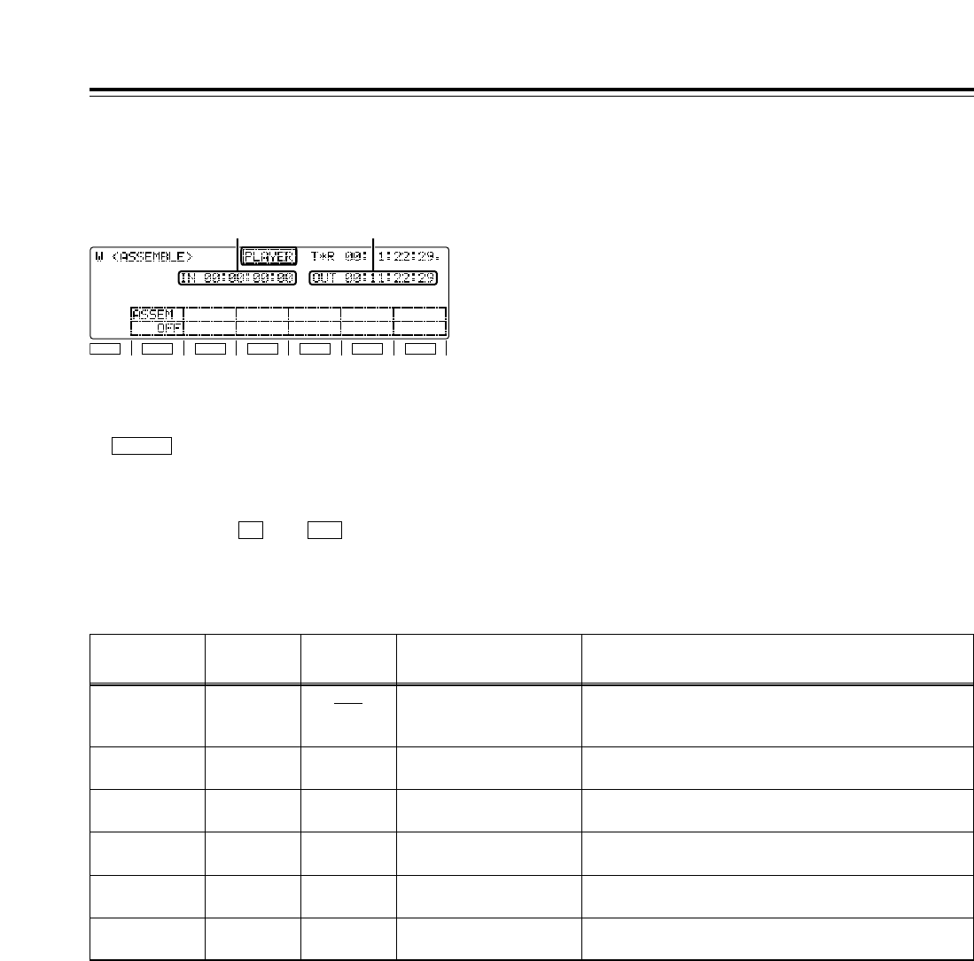
58
Function menus
<ASSEMBLE>
Function
button/item Switching
method Corresponding setup
menu item
F1
ASSEM Toggle ___
Description of setting
For setting the editing mode to ON or OFF.
When the display is highlighted, the ASSEMBLE editing
mode is set to ON, and the ASSEM button lights.
Setting
OFF
ON
F2
___ ___ ___ ______
F3
___ ___ ___ ______
F4
___ ___ ___ ______
F5
___ ___ ___ ______
F6
___ ___ ___ ______
*The underlining (__) denotes the factory setting mode.
The ASSEMBLE editing mode is selected on this
menu screen.
Automatic editing and manual editing
• When the editing mode has been selected (the
button is lighted), automatic editing or
manual editing can be performed even after the
ASSEMBLE screen has been exited.
• After the edit IN and OUT points have been
registered (the and buttons are lighted),
the tape can be prerolled to an IN point or cued up
to an IN or OUT point even after the ASSEMBLE
screen has been exited.
OUTIN
ASSEM
F1
SHIFT
F2 F3 F4 F5 F6
IN point OUT point
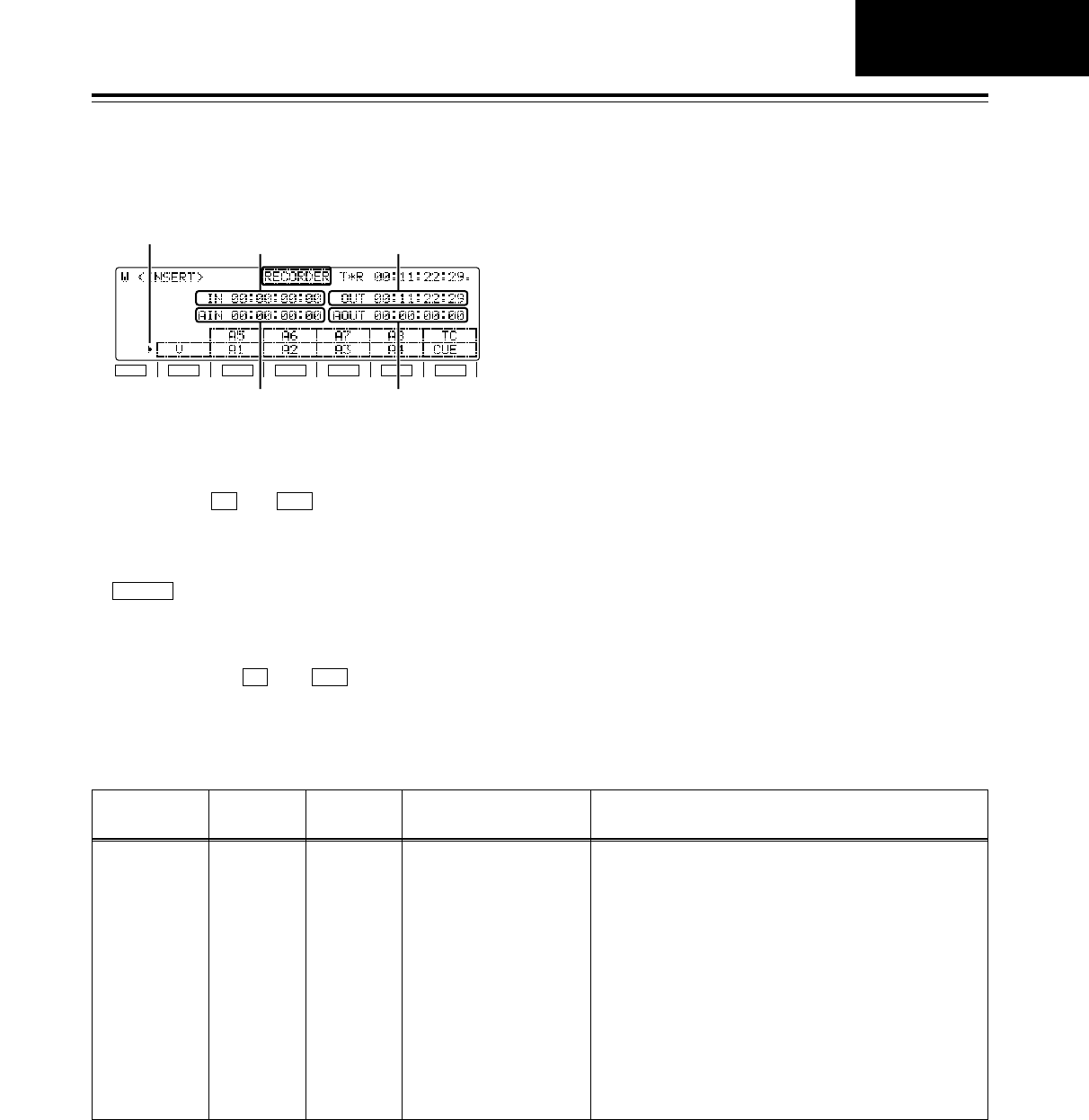
59
Function menus
<INSERT>
Registering the edit points
After the edit IN and OUT points have been
registered, the and buttons light.
Automatic editing and manual editing
• When the editing mode has been selected (the
button is lighted), automatic editing or
manual editing can be performed even after the
INSERT screen has been exited.
• After the edit IN and OUT points have been
registered (the and buttons are lighted),
the tape can be prerolled to an IN point or cued up
to an IN or OUT point even after the INSERT
screen has been exited.
OUTIN
INSERT
OUTIN
Function
button/item Switching
method Corresponding setup
menu item
F1
V
F2
A5, A1
F3
A6, A2
F4
A7, A3
F5
A8, A4
F6
T, CUE
Toggle ___
Description of setting
For setting the editing mode to ON or OFF and selecting
the editing channels.
With the exception of the function button (F1), two channels
are allocated.
Use the SHIFT button to move the marker up or down, and
while specifying the channels, press the function buttons to
select them. Pressing the SHIFT button on other screens
serves a different purpose (screen switching) from its use
here.
For setting the editing mode to ON or OFF.
When one of the channel displays is highlighted, the
INSERT editing mode is set to ON, and the INSERT button
lights.
Setting
___
F1
SHIFT
F2 F3 F4 F5 F6
IN point OUT point
AUDIO IN point
Marker
AUDIO OUT point
The INSERT editing mode and editing channels are
selected on this menu screen.
INSERT
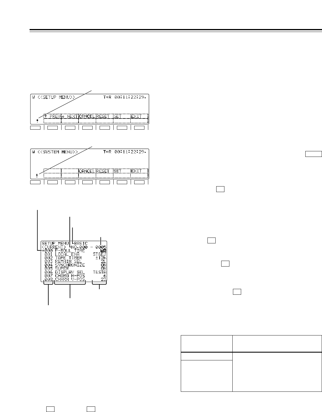
60
Function menus
<SETUP MENU/SYSTEM MENU>
Selecting the menu items
Select the menu item by turning the ADJ dial.
(The cursor is moved down when the dial is turned
clockwise and up when it is turned counter-
clockwise.)
• Forward or reverse page scrolling (SETUP
menu only)
The menu list is organized by category, and the
pages can be scrolled in the forward or reverse
direction on a category by category basis.
(:PREV), (;NEXT)
<Note>
The screen may continue to scroll for a few
moments after the ADJ dial has been turned.
F2F1
Changing the settings
1. In the menu item selection status, press the
ADJ dial.
At this time, the setting of the menu item
indicated by the menu item selection cursor
blinks on the monitor.
2. Turn the ADJ dial to select the setting. (Turn it
clockwise to move up through the settings and
counterclockwise to move down through the
settings.)
When the ADJ dial is pressed again, the menu
item selection status is restored.
<Notes>
• Setting items which have submenus
A submenu is opened by pressing the
button. The same operations as the ones
described above are then used to change the
settings.
• Canceling individual items
When (CANCEL) is pressed, the setting
operation is canceled, and the item selection
status is restored.
F3
SHIFT
F1
SHIFT
F2 F3 F4 F5 F6
F1
SHIFT
F2 F3 F4 F5 F6
Item selection cursor
Monitor display menu
SETUP menu Change mark
Change mark
SYSTEM menu
Item number
Item number
Category
Setting
Setting number
Item name
When the SETUP MENU or SYSTEM MENU opera-
tion menu is selected, a menu list appears on the
monitor, and the respective items can be set.
1.
Settings
2.
Confirmation item Description of setting
EXIT confirmation
When an attempt has been
made to exit the menu
operation after a setting has
been changed without that
setting having been entered
EXIT?
F3: CANCEL
F5: SET(and EXIT)
F6: EXIT(without SET)
Entering settings
(After a setting has been entered, the menu
operation is forcibly exited.)
Press (SET) to enter a setting.
F5
3.
4. Exiting the menu operation
When the (EXIT) button is pressed in the
menu item selection status, the menu operation is
exited, and the original operation screen is
restored.
However, if the (EXIT) button is pressed after
a setting has been changed without that setting
having been entered, a confirmation message will
be displayed.
F6
F6
Confirmation message
<Note>
The “!” mark appears at the bottom left of the screen
when a setting has been changed.

61
Function menus
<SETUP MENU/SYSTEM MENU>
Flow of setting changes
Select the menu
item
Open the
screen.
Close the
screen.
F6 (EXIT)
Submenu
Press the ADJ dial.
Press the ADJ dial.
Turn the ADJ dial.
F iF4 (item reset)
Turn the ADJ dial.
F iF4 (item reset),
FiF5 (SET)
Turn the ADJ dial.
F iF4 (item reset)
Press SHIFT.
Change the setting
Change the setting
SYSTEM MENU function buttons
Function
button/item Switching
method Corresponding setup
menu item
F1
F2
___
F3
CANCEL
___
Press
___
___
Description of setting
___
___
Setting
___
___
F4
RESET Press ___ For resetting an item (while a setting is being changed).
___
F5
SET Press ___ For entering what has been set.
___
F1 (SHIFT)
F2 (SHIFT)
F3 (SHIFT)
F4 (SHIFT)
F5 (SHIFT)
F6 (SHIFT)
___
___ ___ ______
F6
EXIT Press ___ For exiting the special menu (and transferring to the original
menu). (Confirmation message provided)
___
SETUP MENU function buttons
Function
button/item Switching
method Corresponding setup
menu item
F1
:PREV Press ___
Description of setting
For scrolling the on-screen menu pages in the forward
direction.
Setting
___
F2
;NEXT Press ___ For scrolling the on-screen menu pages in the reverse
direction.
___
F4
RESET Press ___ For resetting an item (while a setting is being changed).
___
F5
SET Press ___ For entering what has been set.
___
F6
EXIT Press ___ For exiting the special menu (and transferring to the original
menu). (Confirmation message provided)
___
F3
CANCEL Press ___ ______
F1 (SHIFT)
F2 (SHIFT)
F3 (SHIFT)
F4 (SHIFT)
F5 (SHIFT)
F6 (SHIFT)
___
___ ___ ______
SETUP MENU/
SYSTEM MENU
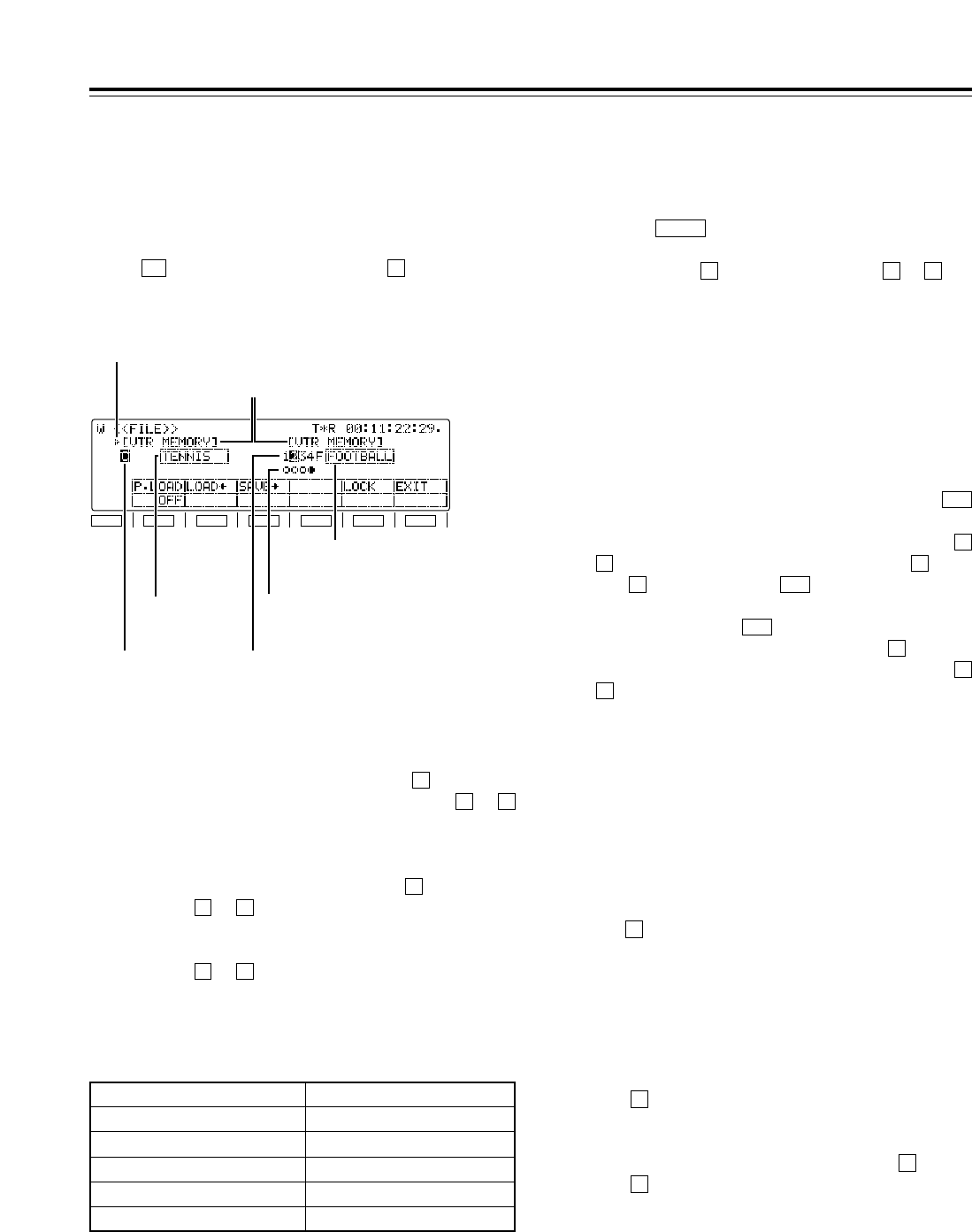
62
Function menus
<FILE>
F1
SHIFT
F2 F3 F4 F5 F6
Memory name
Memory selection cursor
File title
(VTR)
Warning
message
File title
(VTR)
File number
(VTR) File number
(VTR)
File status
(VTR)
• This VTR comes with VTR MEMORY for storing
the current settings (*) and VTR MEMORY to
for storing these settings as a backup.
• Each VTR MEMORY can be provided with a title.
• Data can be saved and loaded and titles can be
copied between VTR MEMORY and VTR
MEMORY to .
• The file locking facility for preventing data from
being overwritten can be engaged for VTR
MEMORY to .
41
41
C
41
C
The current setting information, including the SETUP
menu contents, can be provided with titles and either
saved in or loaded from the backup memory in one of
4 variations.
When (FILE) is pressed while the button is held
down on the <MENU> screen, the following function
menu is displayed.
FF1
Transferring files between memories
After selecting the operation file, press
(LOAD).
The contents of files selected in VTR MEMORY
to can be transferred to VTR MEMORY .
When is selected and (LOAD) is pressed,
the factory setting mode is established.
Alternatively, when (SAVE) is pressed, the
contents of a file in VTR MEMORY can be
transferred to a file selected in VTR MEMORY
to . (The titles are also transferred at the same
time.)
4
1
C
F3
F2F
C4
1
F2
Name of memory area
Initial title (up to 8 characters)
VTR MEMORY C CURRENT
VTR MEMORY 1 USER1
VTR MEMORY 2 USER2
VTR MEMORY 3 USER3
VTR MEMORY 4 USER4
Settings
Selecting the operation file in the selected
memory
The number of the currently selected file is
highlighted on the display. When the ADJ dial is
turned, the highlighting moves to the left or right,
enabling operation files to be selected.
Selecting the memory target
Press the button.
The operation target switches alternately between
VTR MEMORY and VTR MEMORY to .
41C
SHIFT
1.
2.
3.
Editing the title of the selected file
Press the ADJ dial after selecting the operation
file.
The first digit of the title display area is highlighted,
and the file title can be edited.
• To input a number, press the number keys.
• To input letters, tap the numbers keys until the
letter to be input appears while holding down
the button.
More than one letter is allocated to each
number key.
• Turn the ADJ dial to move from one digit to the
next in the title display area.
• To enter the title, press the ADJ dial again.
<Notes>
• When the display screen has been switched or
the button has been pressed during title
editing, the editing enable status is canceled,
and the setting becomes invalid.
• A space can be input by pressing the button
and button.
3
F
C
F
4.
* The term “settings” used here refers to all the settings on
the setup menus excluding the SYSTEM menu, what has
been registered in the PF1 and PF2 menu items, and the
contents of some of the function buttons.
63
Function menus
<FILE>
File overwrite inhibit facility
It is possible to lock the overwrite inhibit facility for
individual files in VTR MEMORY to . Select
the file to be locked, and press (LOCK) to lock
it.
If (LOCK) is pressed again, the facility is
unlocked.
The locked or unlocked mode is displayed in the
file status.
[≤: Unlocked status, µ: locked status]
F5
F5
41
5.
Function
button/item
F1
P. LOAD
F2
LOAD(
F3
SAVE )
Switching
method
Press
Press
Press
Corresponding setup
menu item
A02
P.ON LOAD
Description of setting
Refer to the setup menu.
For downloading data to the current file.
For downloading data to the backup file.
Setting
OFF
USER1
USER2
USER3
USER4
___
___
F4
___ ___ ___
___
___
___
___
F5
LOCK Press ___ For locking the backup file.
___
F1 (SHIFT)
F2 (SHIFT)
F3 (SHIFT)
F4 (SHIFT)
F5 (SHIFT)
F6 (SHIFT)
___
___ ___ ______
F6
EXIT ___ ___ ______
Settings
FILE
*The underlining (__) denotes the factory setting mode.
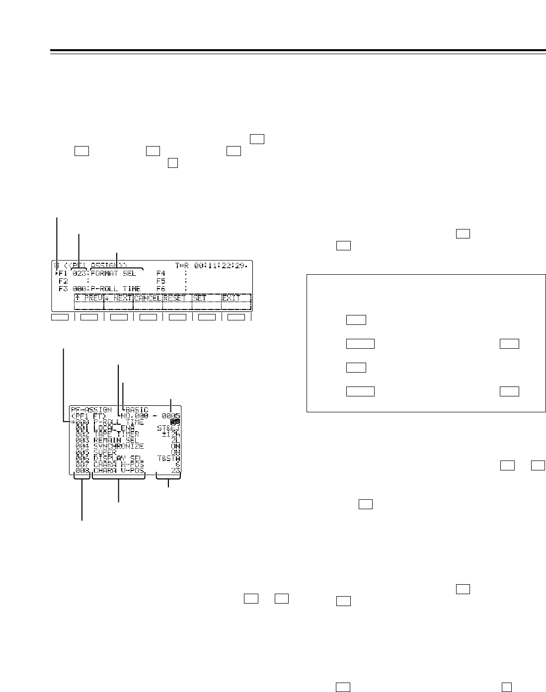
64
Function menus
<PF1/PF2>
F1
SHIFT
F2 F3 F4 F5 F6
Menu name
Selection marker
Registered menu number
Item selection cursor
Item number
Item number
Category
Setting number
Item name
Press (RESET) while holding down the button.
All the registered menu number and name displays
will now go blank.
All the contents of the PF registration file are cleared.
(They cannot be restored.)
FF4
Registration
Clearing the menu items
Clearing all the function button settings
1. Selecting the function buttons
Turn the ADJ dial to move the selection marker,
and select one of the function buttons to
into which the menu items are to be registered. F6F1
2. Entering the function button
Press the ADJ dial.
The display of the function button entered is
highlighted.
1. Turn the ADJ dial to move the selection marker,
and select one of the function buttons to
whose menu items are to be cleared. F6F1
2. Press (RESET). The registered menu
number and name displays will now go blank.
F4
3. To clear the menu items from other function
buttons, repeat steps 1 and 2 above.
4. To save what has been set in the function buttons
in a PF registration file, press (SET).
If (EXIT) is pressed without the settings
having been saved, the above settings will be
canceled.
F6
F5
3. Selecting menu items
Turn the ADJ dial, and select the menu item for
the function button which was selected in step 1
above.
4. Entering the menu items.
Press the ADJ dial.
The target of the ADJ dial operation returns to the
front panel. Whatever was selected in step 3
above is displayed for the registered menu
number and name.
5. To select a menu item for another function button,
repeat steps 1, 2, 3 and 4 above.
6. Saving the settings in a PF registration file
To save what has been set in the function buttons
in a PF registration file, press (SET).
If (EXIT) is pressed without the settings
having been saved, the settings will be canceled.
F6
F5
Up to 24 frequently used setup menu items can be
registered. The items are registered on the function
menus shown below. (No settings have been
registered before the VTR leaves the factory.)
To display one of the function menus, press (PF1
FT), (PF1 BK), (PF2 FT) or (PF2 BK)
while holding down the button on the <MENU
SHIFT> screen.
F
F4F3F2
F1
When menu items are registered, they can be
called simply by pressing the PF1 or PF2 direct
menu button.
When is pressed :
<PF1 FT>
When is pressed after pressing :
<PF1 BK>
When is pressed :
<PF2 FT>
When is pressed after pressing :
<PF2 BK> PF2SHIFT
PF2
PF1SHIFT
PF1
Setting
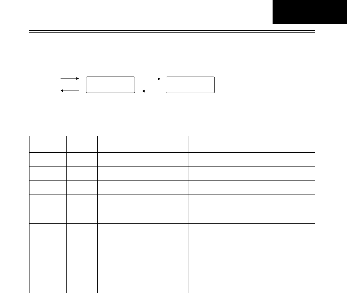
65
Function menus
PF1/PF2 function buttons
Function
button/item Switching
method Corresponding setup
menu item
F1
:PREV Press ___
Description of setting
For scrolling the on-screen menu pages in the forward
direction.
Setting
___
F2
;NEXT Press ___ For scrolling the on-screen menu pages in the reverse
direction.
___
F4
RESET Press
FiPress ___
For clearing one button: what has been selected for the pin
by the individual reset selection marker is cleared.
For clearing all the buttons: what has been registered in all
the pins is deleted from the PF registration files.
___
F5
SET Press ___ For entering the settings. (No confirmation message
provided)
___
F6
EXIT Press ___ For exiting the special menu (and transferring to the original
menu). (Confirmation message provided)
___
F3
CANCEL Press ___ For releasing the menu item selection status.
___
F1 (SHIFT)
F2 (SHIFT)
F3 (SHIFT)
F4 (SHIFT)
F5 (SHIFT)
F6 (SHIFT)
___
___ ___ ______
Flow of function button registration
Select the function
button to be registered.
Select the menu
items.
Open the
screen.
Close the
screen.
F6 (EXIT)
Press the
ADJ dial.
Press the
ADJ dial.
F3 (cancel)
Turn the ADJ dial.
F1 (forward page scroll)
F2 (reverse page scroll)
Turn the ADJ dial.
F4 (one button reset)
F iF4 (all buttons reset)
F5 (settings entered)
<PF1/PF2>
PF1/PF2
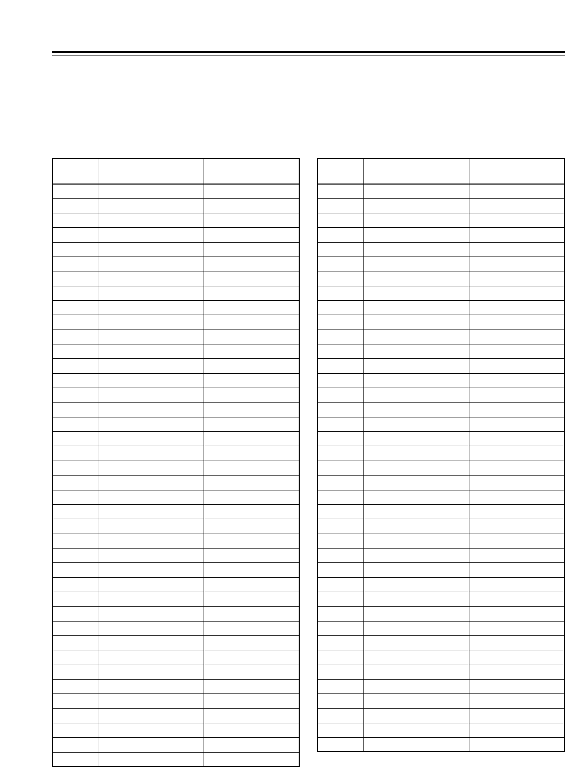
66
Function menus
PF1/PF2 function button names
When SETUP menu items have been registered in the function buttons, the names of these function buttons are
displayed as set forth in the table below.
Setup menu
item No.
Name of setup menu
item Function button name
000 P-ROLL TIME PREROL
001 LOCAL ENA L ENA
002 TAPE TIMER TIMER
003 REMAIN SEL REMAIN
004 SYNCHRONIZE SYNCR
005 SUPER SUPER
006 DISPLAY SEL DISPLY
007 CHARA H-POS C HPOS
008 CHARA V-POS C VPOS
009 CHARA TYPE C TYPE
010 MONI CONTROL MONI C
011 CU-ROLL TIME CU-ROL
012 REC ADJUST REC AJ
013 DET STOP DET ST
014 DET ADJUST DET AJ
015 AUTO STOP STEP
020 SYS FORMAT SYS FT
022 PB FORMAT PB FT
023 FORMAT SEL FMT SL
030 HD FREQUENCY HD FRQ
031 OUT REF OUTREF
100 SEARCH ENA SEARCH
101 SHTL MAX STL MX
102 FF.REW MAX F/R MX
104 REF ALARM REF AL
105 AUTO EE SEL AT EE
106 EJECT EE SEL EJ EE
107 EE MODE SEL EE MD
108 PLAY DELAY PL DLY
109 CAP.LOCK CAPSTN
110 AUTO REW AT REW
111 MEMORY STOP MEM ST
112 FRZ MODE SEL FRZ MD
113 REC INH R INH
114 REC INH LAMP INH LP
115 EJECT SW INH EJ SW
116 EJECT LAMP INH LP
118 SP MODE INH SP MD
131 PAGE MODE PAGE
Setup menu
item No.
Name of setup menu
item Function button name
134 ALARM BEEP AL BP
135 DET BEEP DET BP
140 OUTPUT OUTPUT
141 VOLUME VOLUME
142 AUDIO UNITY A UNI
143 CASSTT LIGHT CAS LT
144 TC INPUT TC IN
145 FRONT LCD F LCD
200 PARA RUN PR RUN
202 ID SEL ID SEL
204 RS232C SEL RS232C
205 BAUD RATE BAND R
206 DATA LENGTH DATA L
207 STOP BIT ST BIT
208 PARITY PARITY
209 RETURN ACK RET AK
212 MASTER PORT MSTR P
300 IN/OUT DEL HD FRQ
301 NEGA FLASH OUTREF
302 CONFI EDIT CONFI
303 AUD EDIT IN AUD I
304 AUD EDIT OUT AUD O
305 AUTO ENTRY AT ENT
306 CF ADJ SEL CF ADJ
307 AFTER CUE-UP AF CUP
308 VAR FWD MAX V F MX
309 VAR REV MAX V R MX
310 JOG FWD MAX J F MX
311 JOG REV MAX J R MX
312 POSTROLL TM POSROL
320 EDIT RPLCE1 RPLCE1
321 EDIT RPLCE2 RPLCE2
322 EDIT RPLCE3 RPLCE3
323 EDIT RPLCE4 RPLCE4
324 EDIT RPLCEC RPLCEC
<PF1/PF2>
132 ROTA MODE ROTATE
133 KEY BEEP KEY BP
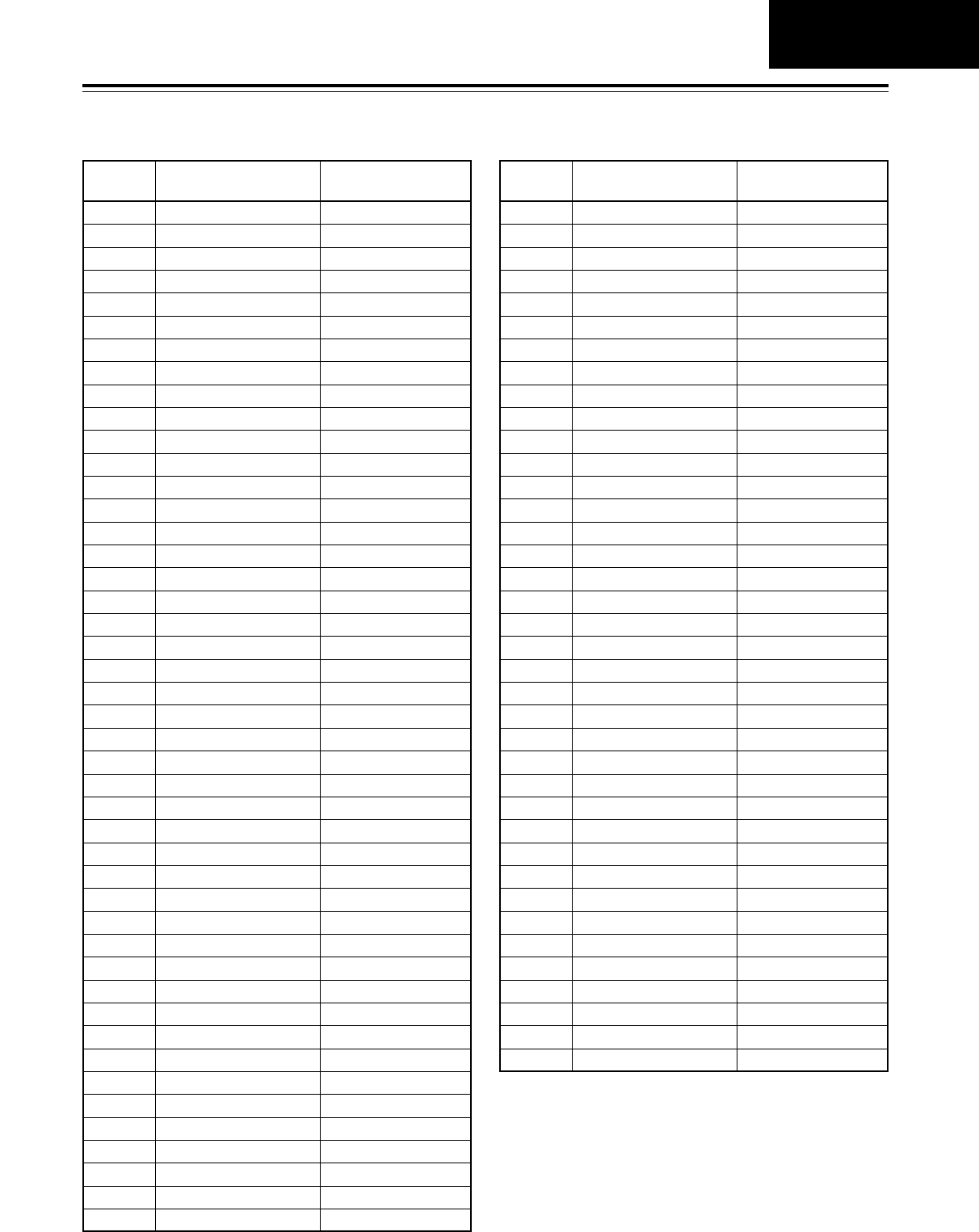
67
Function menus
Setup menu
item No.
Name of setup menu
item Function button name
500 VITC BLANK VI BLK
501 VITC POS-1 VI PS1
502 VITC POS-2 VI PS2
503 TCG MODE TCG MD
504 RUN MODE RUN MD
505 TCG REGEN TCG RG
506 REGEN MODE REG MD
507 TC SOURCE TC SRC
508 BINARY GP BINARY
509 PHASE CORR P CORR
510 TCG CF FLAG TG CFF
511 DF MODE DF MOD
512 TC OUT REF TC REF
513 VITC OUT VITC O
514 HD EMBD VITC ENBD V
515 HD EMBD LTC ENBD L
516 TC OUT ADV TC ADV
517 TCG OUT TCG O
600 VIDEO IN SEL VID IN
601 VIDEO INT SG INT SG
602 SDI IN MODE SDI IN
603 V-MUTE SEL V-MUTE
604 FREEZE SEL FRZ SL
605 INTERPOLATE INTPLT
606 SD MON O SEL SD MOS
620 DOWNCON MODE DW CON
621 UPCONV MODE UP CON
622 D/C RESP H D/C RH
623 D/C RESP V D/C RV
624 U/C RESP H U/C RH
625 U/C RESP V U/C RV
626 D/C ENH H D/C EH
627 D/C ENH V D/C EV
628 U/C ENH H U/C EH
629 U/C ENH V U/C EV
630 1080i#HD_OUT 1080HO
631 1080i#SD_OUT 1080SO
632 720p#HD_OUT 720pHO
633 720p#SD_OUT 720pSO
Setup menu
item No.
Name of setup menu
item Function button name
642 I U/C ENH V IUC EV
650 STYLE STYLE
651 HUE STYLE (SD) HUE S
653 Y LVL (HD) Y HD
654 Pb LVL (HD) Pb HD
655 Pr LVL (HD) Pr HD
656 BK LVL (HD) BK HD
658 Y LVL (SD) Y SD
659 Pb LVL (SD) Pb SD
660 Pr LVL (SD) Pr SD
661 BK LVL (SD) BK SD
662 V LEVEL V LV
663 C LEVEL C LV
664 HUE (C PHASE) HUE
665 SETUP (BK) LVL SUP LV
670 BRIGHT BR
671 R-BRIGHT R-BR
672 B-BRIGHT B-BR
673 CONTRAST CT
674 R-CONTRAST R-CT
675 B-CONTRAST B-CT
676 BLK CLIP B LIP
680 CC (F1) BLANK CC1 BK
681 CC (F2) BLANK CC2 BK
684 EDH (SD) EDH SD
685 ESR MODE (SD) ESR SD
686 CCR MODE (SD) CCR SD
687 SDI INDEX O SDI IX
688 CC REC CC REC
695 BLANK LINE BK L
<PF1/PF2>
634 480p#HD_OUT 480pHO
635 480p#SD_OUT 480pSO
636 480i#HD_OUT 480iHD
637 480i#SD_OUT 480iSD
638 IN U/C MODE IUC MD
639 I U/C RESP H IUC RH
640 I U/C RESP V IUC RV
641 I U/C ENH H IUC EH
400 STILL TIMER STILL
401 SRC PROTECT SRC PT
402 DRUM STDBY DRUM
403 STOP PROTECT STP PT
PF1/PF2
68
Function menus
Setup menu
item No.
Name of setup menu
item Function button name
713 CH1 IN SEL A1 IN
714 CH2 IN SEL A2 IN
715 CH3 IN SEL A3 IN
716 CH4 IN SEL A4 IN
717 CH5 IN SEL A5 IN
718 CH6 IN SEL A6 IN
719 CH7 IN SEL A7 IN
720 CH8 IN SEL A8 IN
721 D IN SEL12 DIN 12
722 D IN SEL34 DIN 34
723 D IN SEL56 DIN 56
724 D IN SEL78 DIN 78
725 REC CH1 REC A1
726 REC CH2 REC A2
727 REC CH3 REC A3
728 REC CH4 REC A4
729 REC CH5 REC A5
730 REC CH6 REC A6
731 REC CH7 REC A7
732 REC CH8 REC A8
733 REC CUE RECCUE
734 PB FADE PB FD
735 HD EMBD AUD HDEM A
736 SD EMBD AUD SDEM A
737 MONI MIX M MIX
738 CH1 CUE SEL A1 CSL
739 CH2 CUE SEL A2 CSL
740 CH3 CUE SEL A3 CSL
741 CH4 CUE SEL A4 CSL
Setup menu
item No.
Name of setup menu
item Function button name
<PF1/PF2>
700 CH1 IN LV A1 ILV
701 CH2 IN LV A2 ILV
702 CH3 IN LV A3 ILV
703 CH4 IN LV A4 ILV
704 CUE IN LV AC ILV
705 CH1 OUT LV A1 OLV
706 CH2 OUT LV A2 OLV
707 CH3 OUT LV A3 OLV
708 CH4 OUT LV A4 OLV
709 CUE OUT LV AC OLV
710 MONIL OUT LV ML OLV
711 MONIR OUT LV MR OLV
712 MONI OUT MONI O
746 MONI CH SEL MON CH
747 MON AUTO SEL MON AT
748 MONI SEL INH MS INH
749 AUDIO PB VR APB VR
750 ANA CH1 SEL AA1 SL
751 ANA CH2 SEL AA2 SL
752 ANA CH3 SEL AA3 SL
753 ANA CH4 SEL AA4 SL
754 SD SDI CH1 SL SSA1SL
755 SD SDI CH2 SL SSA2SL
756 SD SDI CH3 SL SSA3SL
757 SD SDI CH4 SL SSA4SL
758 JOG PROC JOG P
742 CH5 CUE SEL A5 CSL
743 CH6 CUE SEL A6 CSL
744 CH7 CUE SEL A7 CSL
745 CH8 CUE SEL A8 CSL
759 DV PB ATT DV ATT
760 REC PT MUTE R PTMT
761 AUDIO INT SG A INSG
762 AUD RATE CON A RC
763 METER SCALE M SCL
790 CUE REC VOL CR VOL
791 CUE PB VOL CP VOL
A02 P.ON LOAD P.LOAD
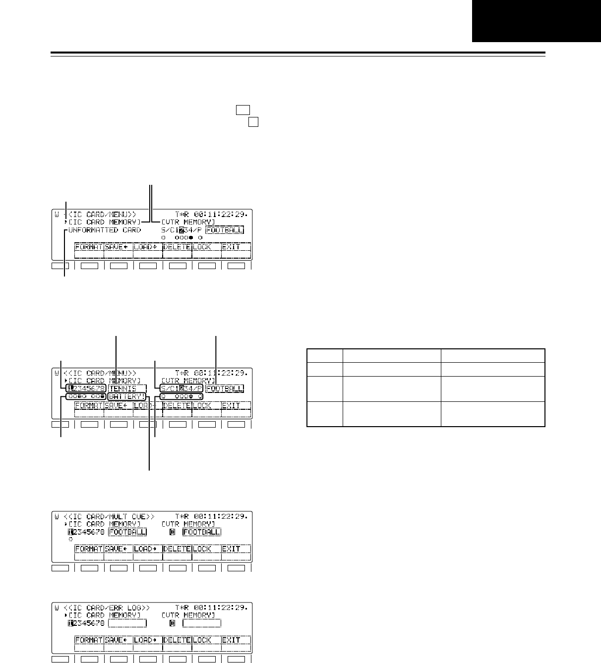
69
<CARD>
F1
SHIFT
F2 F3 F4 F5 F6
Memory name
Memory selection
cursor
Warning message 1
F1
SHIFT
F2 F3 F4 F5 F6
Warning message 2
File status (VTR)
File number
(VTR) File number
(CARD)
File title (CARD) File title (VTR)
File status (CARD)
F1
SHIFT
F2 F3 F4 F5 F6
F1
SHIFT
F2 F3 F4 F5 F6
SYSTEM MENU/SETUP MENU/50PIN ASSIGN
File status
[MENU/ERROR LOG/MULTI CUE]
The settings and information can be saved onto or
loaded from the IC card memory. When (CARD)
is pressed on the <MENU> screen while the button
is held down, the function menu shown below is
displayed.
F
F2
MULTI CUE
ERROR LOG
Warning message 1
Warnings concerning the IC card are displayed here.
NO CARD
The IC card has not been inserted.
UNFORMATTED CARD
The IC card is not formatted.
HD150 FORMAT!
This card was formatted by the AJ-HD150.
HD1500 FORMAT!
This card was formatted by the AJ-HD1500.
Warning message 2
BATTERY!
This appears when the battery inside the IC card has
no charge left. It signifies that it is time to replace the
battery.
PROTECT!
The IC card protection is set to ON.
File status (CARD) File status (VTR)
No storage files are present.
- - - - -Blank
Storage files are present.
(Unlocked status)
The target file is in the
unlocked status.
≤
Storage files are present.
(Locked status)
The target file is in the
locked status.
µ
Function menus
<Notes>
• IC cards are not compatible with other VTR models.
• The IC cards which can be used are the 68-pin two-
piece type of SRAM cards (64KB or more) with
replaceable battery. Model number BN-064HSR is
recommended.
CARD
70
IC card data layout VTR memory data layout
Current
MULTI CUE MULTI CUE
Lock
≤<>
Lock
k
1
2
3
4
5
6
7
Current
ERROR LOG ERROR LOG
≤<>
k
1
2
3
4
5
6
7
8
8
• The SETUP MENU (current, USER1 to USER4)
and SYSTEM MENU settings, 50PIN ASSIGN
registration data, MULTI CUE registered points and
ERROR LOG data in the VTR MEMORY in this
VTR can be saved in and loaded from the IC cards.
• Titles can be provided for all the data files, and
when the files are saved or loaded, the titles are
also copied at the same time.
• For those data files which have been saved in the
IC card, a file lock facility can be engaged to
prevent the data in those files from being
overwritten.
Function menus
<CARD>
[MENU/ERROR LOG/MULTI CUE]
Transferring files between memories
• VTR MEMORY >IC CARD MEMORY
First select the operation file, and then press
(SAVE).
• IC CARD MEMORY >VTR MEMORY
First select the operation file, and then press
(LOAD).
<Note>
The title is also transferred at the same time.
F3
F2
Settings
Selecting the operation files inside the
selected memory
The number of the currently selected file is
highlighted.
Turn the ADJ dial to select the file to be operated.
• For SYSTEM MENU, SETUP MENU and 50PIN
ASSIGN
The details of the registration status display for
the IC CARD MEMORY are automatically
switched depending on whether S (SYSTEM
MENU), C1234 (SETUP MENU) or P (50PIN
ASSIGN) is selected at the VTR MEMORY
side.
Selecting the targeted memory
Press the button.
The operation target is switched alternately
between the IC CARD MEMORY and VTR
MEMORY.
SHIFT
1.
2.
3.
IC card data layout VTR memory data layout
Current
USER1
USER2
USER3
USER4
SETUP MENU
SETUP MENU
(what has been
registered for
the PF1, PF2
menu items,
contents of
some function
buttons)
Lock
≤<>
Lock
k
≤
≤
≤
≤
1
2
3
4
5
6
7
Current
50 PIN ASSIGN 50 PIN ASSIGN
≤<>
≤
1
2
3
4
5
6
7
Current
SYSTEM MENU SYSTEM MENU
≤<>
≤
1
2
3
4
5
6
7
8
8
8
71
Function menus
Function
button/item Switching
method Corresponding setup
menu item
F1
FORMAT FiPress ___
Description of setting
For formatting the IC card.
Setting
___
F2
SAVE<
Press ___ For transferring data to the IC card files.
___
F4
DELETE FiPress ___ For deleting IC card files.
___
F5
LOCK Press ___ For locking IC card files or VTR MEMORY files.a
___
F6
EXIT ___ ___ ______
F3
LOAD>
Press ___ For transferring data from the IC card files.
___
F1 (SHIFT)
F2 (SHIFT)
F3 (SHIFT)
F4 (SHIFT)
F5 (SHIFT)
F6 (SHIFT)
___
___ ___ ______
<CARD>
Editing the title of a selected file
First select the operation file, and then press the
ADJ dial.
The first digit of the title display area is highlighted,
indicating that the file title can now be edited.
• To input a number, press the number keys.
• To input letters, tap the numbers keys until the
letter to be input appears while holding down
the button.
More than one letter is allocated to each
number key.
• Press the ADJ dial to move from one digit to the
next on the title display area.
• To enter the title, press the ADJ dial again.
<Notes>
• When the display screen has been switched or
the button has been pressed during title
editing, the editing enable status is canceled,
and the setting becomes invalid.
• A space can be input by pressing the button
and button.
3
F
C
F
4. File overwrite inhibit facility
It is possible to lock the overwrite inhibit facility for
individual files in the IC CARD MEMORY.
• Locking a file
Select the file to be locked, and press
(LOCK).
• Unlocking a file
Press (LOCK) again.
<Note>
The locked or unlocked status is displayed in the
file status.
[≤: Unlocked status, µ: locked status]
F5
F5
5.
CARD
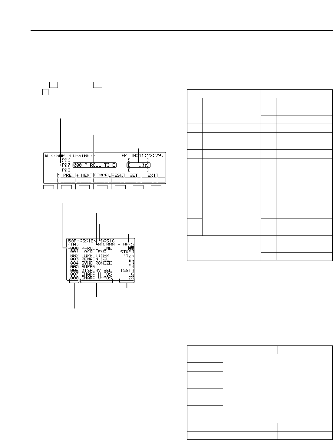
72
Function menus
F1
SHIFT
F2 F3 F4 F5 F6
Registered item name
Registered value
Selection marker
<50P IN/OUT ASSIGN>
Pins in which functions can be registered
IN pins: Pins 6 to 20, 22, 23, 25
OUT pins: Pin 21, 24, pins 32 to 46, 48
All other pins are reserved and cannot be changed.
Using the front panel controls and on-screen menus,
functions are registered into the input pins of the
parallel remote (50PIN) connector and the statuses
are registered into its output pins.
When (50P IN) or (50P OT) is pressed while
the button is held down on the <MENU SHIFT>
menu, the function menu shown below appears, and
functions can be registered or deleted.
F
F6F5
Items which can be registered in the input and
output pins
Items identical to the setup menu items can be
registered in both the input and output pins. In
addition, there are a set of special items can be also
registered in the input pins and another set for the
output pins.
<Note>
System menu and submenu items cannot be
registered.
IN pins OUT pins
1 REC
21
Range of pins to which any
items can be assigned
24
26 <Power>
27 REC
28 PLAY
29 FF
30 REW
31 STOP
32
Range of pins to which
any items can be
assigned
:
l
;
46
48
47 <GND>
49 <GND>
50 <GND>
2 PLAY
3FF
4 REW
5 STOP
6
Range of pins to which
any items can be
assigned
:
l
;
20
22
23
25
Registration in input pins
Setup menu list
Special IN menu list
<No display>
<No display>
Special OUT menu list
Registration in output pins
100
000
Item no.
200
300
400
500
600
700
B00
C00
Registered item names
Setup menu items and 50PIN special menu items can
be registered in the parallel remote connector pins,
and the names of these menu items are displayed.
Registered values
One setting for the registered menu item is displayed
in each of the pins.
When active signals are input to the IN pins in which
the setup menu items mentioned above have been
registered, the settings for the registered menu items
take effect inside the VTR.
When the settings for the registered menu items tally
with the registered values, active signals are output
from the registered OUT pins.
Item selection cursor
Item number
Item number
Category
Setting
Setting number
Item name
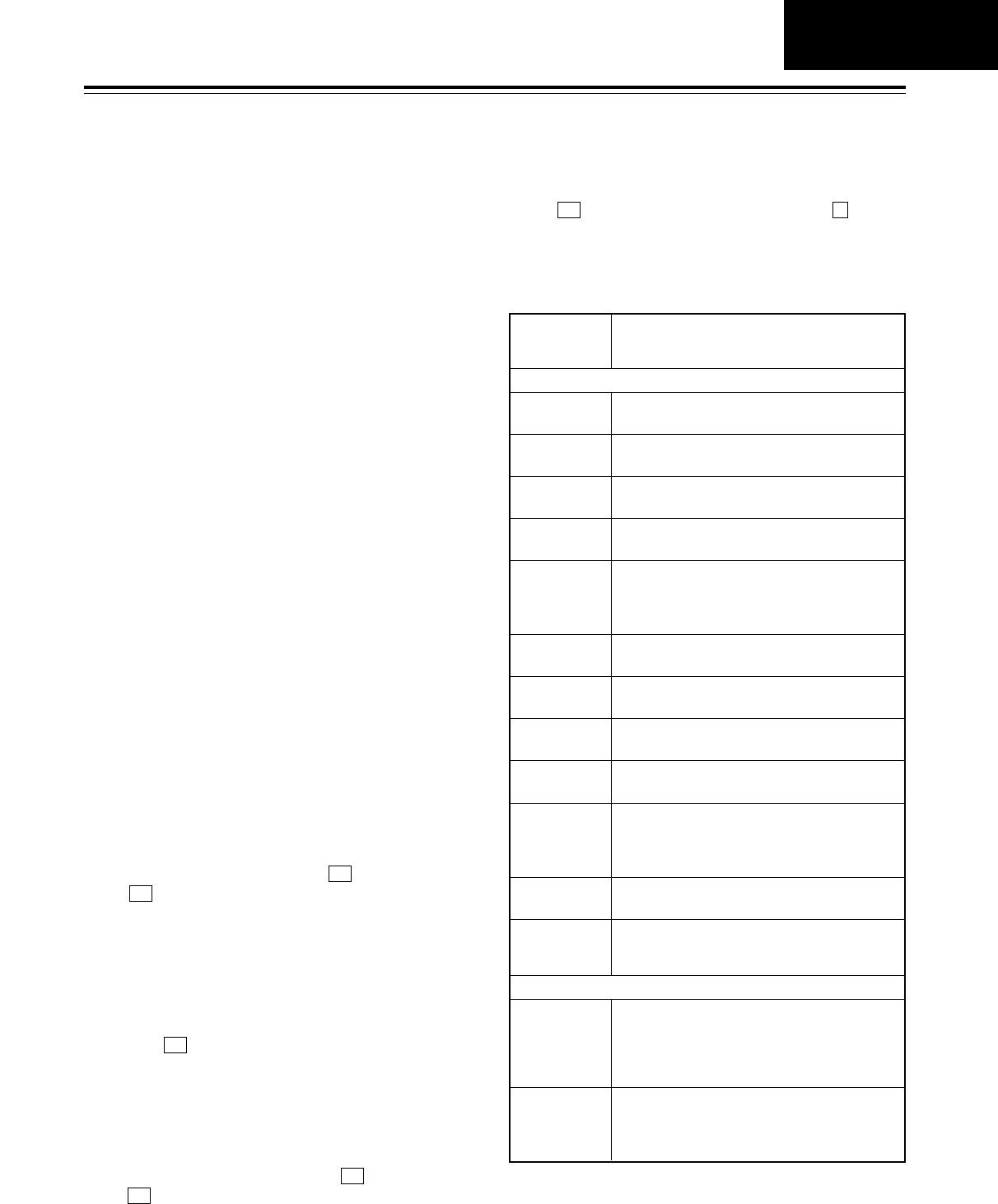
73
Function menus
<50P IN/OUT ASSIGN>
Press (RESET) while holding down the button.
All the registered item names and registered values
are now set to the factory settings. (These settings
cannot be restored.)
FF4
Registering functions in the input pins/Active inputs
Registering functions in the output pins/Active outputs
Clearing
Resetting all the items and values
1.
Selecting the 50-pin connector pins
Turn the ADJ dial to move the selection marker and
select the pin of the 50-pin connector into which the
menu item is to be registered.
2.
Entering the 50-pin connector pins
Press the ADJ dial.
The entered 50-pin connector pin display is highlighted.
4. Entering the menu item
Press the ADJ dial.
The on-screen setting display now blinks.
1.
Turn the ADJ dial to move the selection marker and select the
pin of the 50-pin connector whose menu item is to be cleared.
2. Press (RESET). The registered item name
and registered value displays now go blank.
F4
3. To clear the menu items in other 50-pin connector
pins, repeat steps 1 and 2.
3.
Selecting the menu item
Turn the ADJ dial and select the menu item for the pin
of the 50-pin connector which was selected in step 1
above.
5. Selecting the setting
Turn the ADJ dial and select the setting for the
menu item which was selected in step 3 above.
6.
Entering the setting
Press the ADJ dial
.
What is to be operated by the ADJ dial returns to the
front panel. Whatever was selected in step 3 is
displayed as the registered item name and whatever was
selected in step 5 is displayed as the registered value.
7. To select menu items and settings for other 50-pin
connector pins, repeat steps 1 to 6.
8. Saving the data in the 50-pin registration file
To save what has been set in the 50-pin connector in
the 50-pin registration file, press (SET).
If (EXIT) is pressed without the above settings
have been saved, those settings will be canceled.
F6
F5
Special IN menu list
No.
SUPER
DISPLAY Description of setting
B00
STBY ON For transferring to the STANDBY ON mode.
B01
STBY OFF For transferring to the STANDBY OFF mode.
B02
STBY ONOFF For alternately transferring to the STANDBY ON
and OFF mode.
B03
EJECT For transferring to the EJECT mode.
B04
CUE For prerolling the tape to the IN point when the
IN point has been registered; for prerolling the
tape to the current point when the IN point has
not been registered.
B05
IN SET For registering the edit IN point.
B06
STILL For transferring to the still picture (STILL) mode.
B07
422 REM ON The 9-pin connector functions.
B08
422 REM OFF The 9-pin connector does not function.
B09
TC EXT For returning TC SOURCE to the previous EXT
mode.
(No switching occurs if the EXT mode is
currently established
.)
B10
TC INT AUTO For switching TC SOURCE to INT and TCG
MODE to AUTO.
B20
PROTECT
HALF
For switching the tape protection mode operation to
half-loading in the event that the VTR has been left
standing in the STOP mode or the STILL mode while
any of the search modes (JOG, VAR or SHTL) was
established.
B21
PROTECT
T-REL
For switching the tape protection mode operation to
tension release when the VTR has been left standing
in the STOP mode or the STILL mode while any of the
search modes (JOG, VAR or SHTL) was established.
Functions not featured on the setup menua
SRC PROTECT and STOP PROTECT settings switched simultaneously
4.
To save what has been set in the 50-pin connector in
the 50-pin registration file, press (SET).
If (EXIT) is pressed without the above settings
have been saved, those settings will be canceled.
F6
F5
50P IN/OUT
ASSIGN
B11
TC EXT_L
REG
For switching TC SOURCE to EXT_L and TCG
MODE to REGEN.
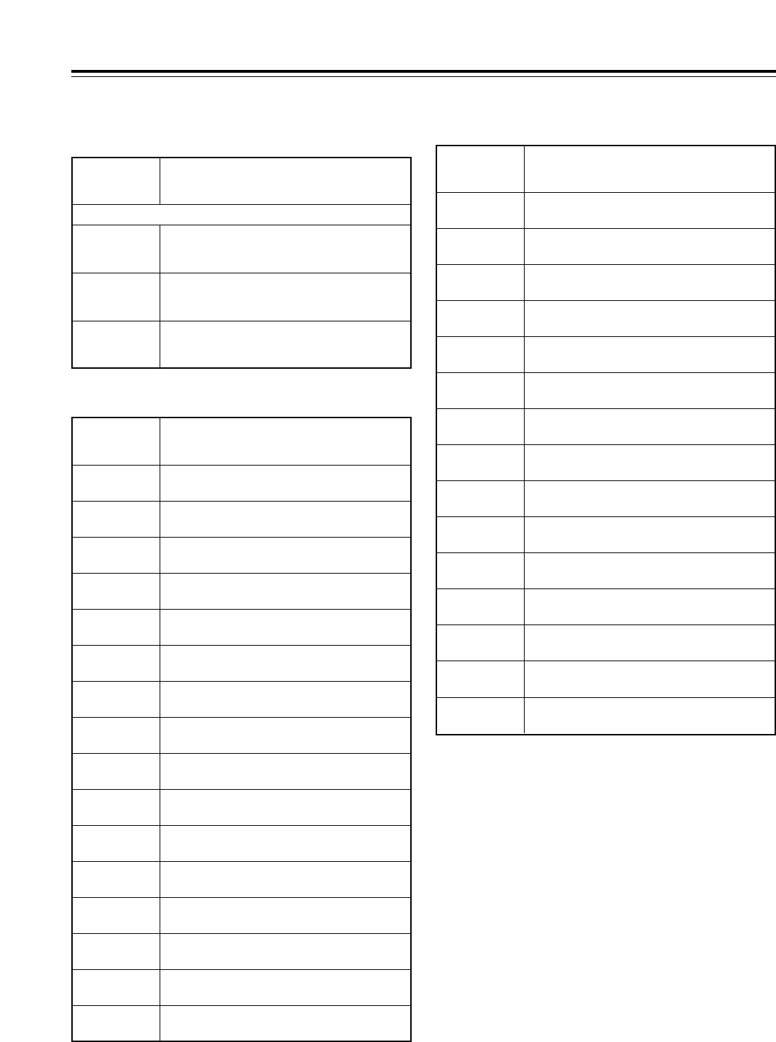
74
Function menus
Special IN menu list (continued)
Special OUT menu list
No.
SUPER
DISPLAY Description of setting
B22
UD FIT_V
For switching the picture angle during down-conversion to
letter box and the picture angle during up-conversion to the
top/bottom cut status in the vertical direction.
B23
UD FIT_H
For switching the picture angle during down-
conversion to the side cut mode and the picture angle
during up-conversion to the side panel mode.
B24
UD FIT_HV
For switching the picture angle during down-
conversion to the squeeze mode and the picture
angle during up-conversion to the stretch mode.
UPCON MODE and DOWNCON MODE settings switched simultaneously
No.
SUPER
DISPLAY Description of setting
C00
EJECT EJECT status
C01
STBY ON STANDBY ON status
C02
CUE CUE-UP completed status
C03
STILL STILL status
C04
PANEL STOP Status in which the front panel STOP button is
pressed down
C05
PRE CTL Status of whether to inhibit overwrite during
normal recording
C06
422 REM ON 9-pin connector function status
C07
REMOTE 50-pin connector function status
C08
REC INH1 Recording inhibit status 1
C09
REC INH2 Recording inhibit status 2
C10
CAS INH1 Tape recording inhibit status 1
C11
CAS INH2 Tape recording inhibit status 2
C12
TC SRC1 TC input status 1
No.
SUPER
DISPLAY Description of setting
C16
DC3 Down-conversion status 3
C17
UC1 Up-conversion status 1
C18
UC2 Up-conversion status 2
C19
UD1 Up-conversion/down-conversion status 1
C20
UD2 Up-conversion/down-conversion status 2
C21
UD3 Up-conversion/down-conversion status 3
C22
ERR0 Error status 0
C23
ERR1 Error status 1
C24
ERR2 Error status 2
C26
CH GREEN Channel condition green LED
C27
CH AMBER Channel condition amber LED
C28
CH RED Channel condition red LED
C29
SERVO LOCK
Servo lock LED
C30
V UNITY Video UNITY LED
C31
A UNITY Audio UNITY LED
<50P IN/OUT ASSIGN>
C13
TC SRC2 TC input status 2
C14
DC1 Down-conversion status 1
C15
DC2 Down-conversion status 2

75
C22
ERR0 C23
ERR1 C24
ERR2 Error status
000
SERVO NOT LOCKED (priority level 1)
001
SERVO LOCKED (priority level 4)
010
HIGH ERROR (amber) (priority level 3)
011
HIGH ERROR (red) (priority level 2)
Error statuses
C12
TC SRC1 C13
TC SRC2 TC input status
00
External SLTC
01
External LTC
10
External SVITC (or external VITC with SD input)
11
INT
TC input statuses
C10
CAS INH1
C11
CAS INH2
Tape recording inhibit status
00
Cassette recording enabled
01
Cassette accidental erasure prevented
Tape recording inhibit statuses
Recording inhibit statuses
Function menus
<50P IN/OUT ASSIGN>
C08
REC INH1 C09
REC INH2 Recording inhibit statuses
00
Overwriting prohibited during normal recording
01
All recording onto cassette prohibited
10
Recording inhibit mode other than the 2 above modes
11
Recording onto cassette enabled
Down-conversion statuses
C14
DC1 C15
DC2 C16
DC3 Down-conversion status
000
Squeeze mode
010
Side cut modea
100
Letter box mode
110
14:9
111
13:9
Up-conversion statuses
C17
UC1 C18
UC2 Up-conversion status
00
Stretch mode
01
Side panel mode
10
Top and bottom cut in vertical direction
Up-conversion down-conversion statuses
C19
UD1 C20
UD2 C21
UD3 Down-conversion
status Up-conversion
status
000
Squeeze mode
010
Side cut mode
100Letter box mode
Stretch mode
Side panel mode
Top and bottom cut
in vertical direction
111 Any other combination
The statuses established by a multiple number of pins
in the special OUT menu list are displayed. Pin status
“1” signifies “active low” and “0” signifies “open.”
50P IN/OUT
ASSIGN
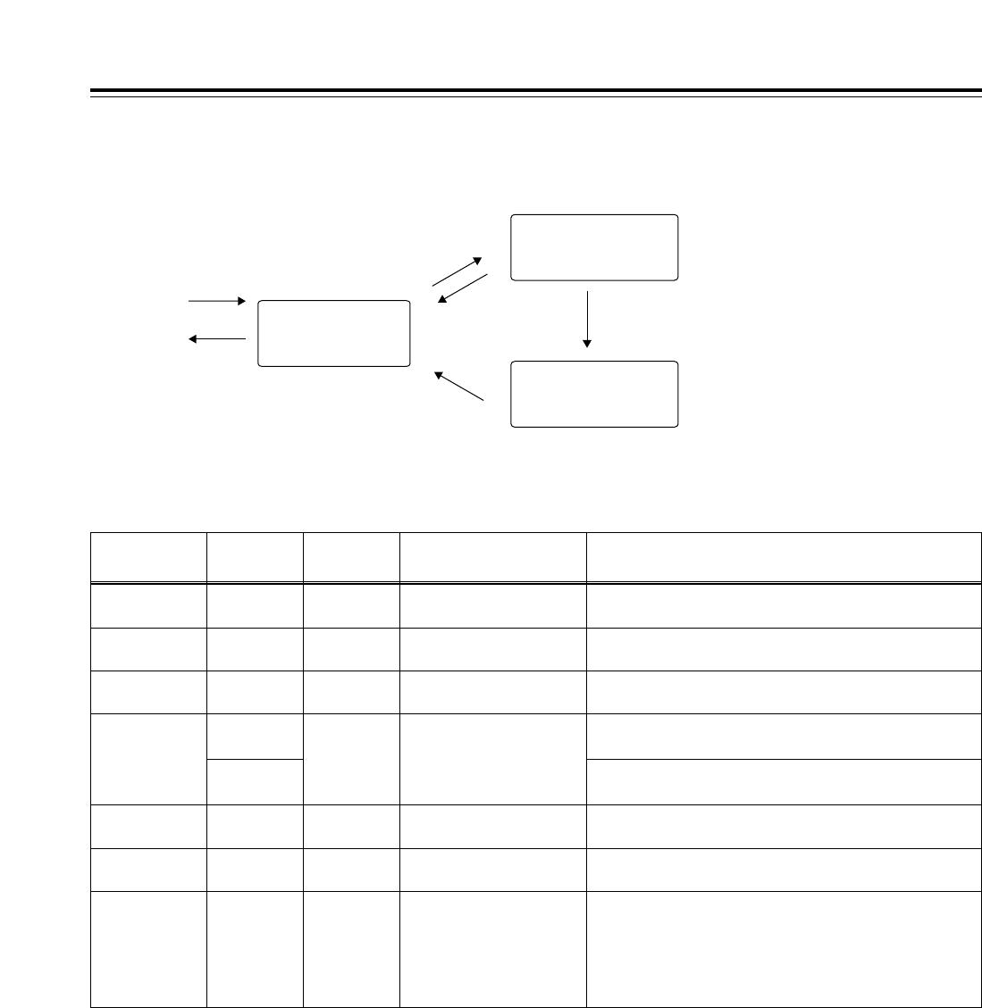
76
Function menus
<50P IN/OUT ASSIGN>
50P IN/OUT ASSIGN function buttons
Function
button/item Switching
method Corresponding setup
menu item
F1
:PREV Press ___
Description of setting
For scrolling the on-screen menu pages in the forward
direction.
Setting
___
F2
;NEXT Press ___ For scrolling the on-screen menu pages in the reverse
direction.
___
F4
RESET Press
FiPress
___
For resetting one pin: what has been selected for the pin
selected by the individual reset selection marker is cleared.
For resetting all the pins: what has been registered in all the pins is
set to the factory settings and set in the 50-pin registration file.
___
F5
SET Press ___ For registering the file; all the function button settings are
saved in the 50-pin registration file.
___
F6
EXIT Press ___ For exiting the special menu (and transferring to the original
menu).
___
F3
CANCEL Press ___ For releasing the menu item selection status.
___
F1 (SHIFT)
F2 (SHIFT)
F3 (SHIFT)
F4 (SHIFT)
F5 (SHIFT)
F6 (SHIFT)
___ ___ ______
Flow of registration
Status in which regis-
tered 50-pin connector
pin selection is enabled
Status in which selected 50-
pin connector pin menu item
selection is enabled
Status in which selected
menu item setting
selection is enabled
Open the
screen.
Close the
screen.
F6 (EXIT)
Press the ADJ dial.
F3 (cancel)
Press the ADJ dial.
F3 (cancel) Press the ADJ dial.
Turn the ADJ dial.
F4 (one pin reset)
F iF4 (all pins reset)
F5 (settings entered)
Turn the ADJ dial.
F1 (forward page scroll)
F2 (reverse page scroll)
Turn the ADJ dial.
77
Function menus
<50P IN/OUT ASSIGN>
50-pin assignment factory settings
Pin
no. I/O Setting item
1I
REC
2I
PLAY
3I
FF
4I
REW
5I
STOP
6I
___
7I
___
8I
422 REMOTE ON
9I
422 REMOTE OFF
10 I LOCAL ENABLE
11 I EJECT
12 I IN SET
13 I REC INH ALL
14 I REC INH PRE
15 I LOCAL DISABLE
16 I TC EXT
17 I TC INT&TCG MODE AUTO
18 I ___
19 I ___
20 I STNDBY ON/OFF
21 O ERR0 STATUS
22 I DET STOP ON
23 I CUE
24 O ERR1 STATUS
25 I DET STOP OFF
26 Power
27 O REC STATUS
28 O PLAY STATUS
29 O FF STATUS
30 O REW STATUS
31 O STOP STATUS
32 O 422 REMOTE STATUS
33 O EJECT STATUS
34 O ERR2 STATUS
35 O TC SRC1 STATUS
36 O TC SRC2 STATUS
37 O ___
38 O ___
39 O REC INH1 STATUS
40 O REC INH2 STATUS
Pin
no. I/O Setting item
41 O CUE STATUS
42 O REMOTE STATUS
43 O DET STOP STATUS
44 O PRE CTL DETECTED STATUS
45 O LOCAL ENABLE STATUS
46 O STANDBY ON STATUS
47 GND
48 O ___
49 GND
50 GND
“__” denotes that nothing is subject to control or to a status.
50P IN/OUT
ASSIGN
<Notes>
• For a command, input TTL level signals; for an
active low edge, input an electrical signal of 100 ms
or more.
• For a status, a maximum open collector and sink
current of 6 mA is output.
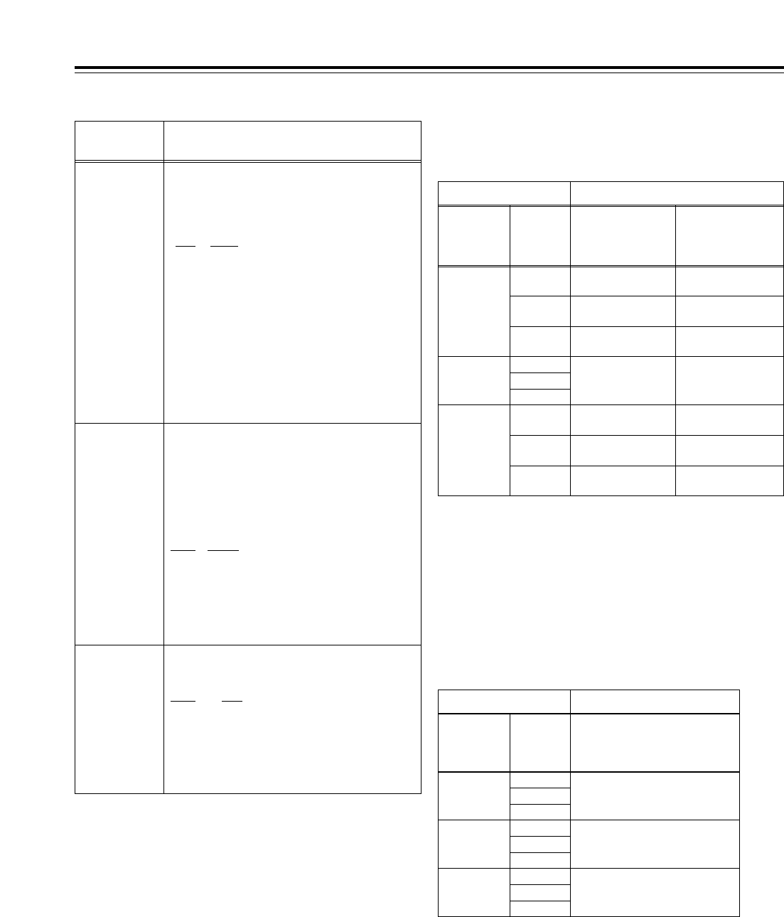
LOCAL HD
HD
AJ-HD1700
External encoder remote
controller
SD
BOTH
SD
BOTH
BOTH HD External encoder remote
controller/AJ-HD1700
SD
BOTH
Setting Adjustment item
05:
ENCODER
SEL
06:
V LEVEL
CTRL
662: V LEVEL
663: C LEVEL
664: HUE ( or C PHASE)
665: SETUP LVL (or BK LVL)
REMOTE
78
System menus
No./Item Description of setting
The underlining (__) denotes the factory setting mode.
00
WFM SEL
This enables one of a number of different signals
to be output from the VIDEO OUT 2 output
connector.
0000 CTL
:The CTL signal is output.
0001 TC
:The time code signal is output.
0002 VIDEO
:
The video output signal is output.
0003 RF_L
:The PB L RF signal is output.
0004 RF_R
:The PB R RF signal is output.
0005 ENV_L
:The PB L ENV signal is output.
0006 ENV_R
:The PB L ENV signal is output.
<Notes>
• The setting can be changed at any time without
being affected by the system menu item No.30
(MENU LOCK) setting.
• The output signals during normal playback
virtually maintain the levels given below.
CTL: 0.1 to.3Vp-p TC: 0.6Vp-p
VIDEO: 1.0Vp-p
05
ENCODER
SEL
For setting whether to perform the various
adjustments for the video output signals using this
VTR or using an external encoder remote
controller.
0000
REMOTE:
The various adjustments for the video output
signals are performed by an external encoder
remote controller.
0001
LOCAL:
The various adjustments for the video output
signals are performed using this VTR.
0002 BOTH:
The various adjustments for the video output
signals are performed using both this VTR and
an external encoder remote controller.
06
V LEVEL
CTRL
For selecting what is to be controlled when
the video output level is to be adjusted by an
external encoder remote controller.
0000 HD:
The HD video output level can be adjusted.
0001 SD:
The SD video output level can be adjusted.
0002 BOTH:
Both the HD and SD video output levels can be
adjusted.
Video output signal adjustments
The control matrix for the adjustments is shown in the table below.
LOCAL HD
HD
AJ-HD1700
External encoder
remote controller
AJ-HD1700
No adjustments
possible
External encoder
remote controller
No adjustments
possible
External encoder
remote controller
External encoder
remote controller
SD
BOTH
SD
BOTH
BOTH HD
External encoder remote
controller/AJ-HD1700
AJ-HD1700
External encoder remote
controller/AJ-HD1700
AJ-HD1700
External encoder remote
controller/AJ-HD1700
External encoder remote
controller/AJ-HD1700
SD
BOTH
Setting Adjustment item
05:
ENCODER
SEL
06:
V LEVEL
CTRL
653: Y LVL (HD)
654: Pb LVL (HD)
655: Pr LVL (HD)
656: BK LVL (HD)
658: Y LVL (SD)
659: Pb LVL (SD)
660: Pr LVL (SD)
661: BK LVL (SD)
REMOTE
External encoder remote controller: Only adjustments of the
external encoder remote controller are performed.
AJ-HD1700: Only adjustments of the setup menu items are
performed.
External encoder remote controller/AJ-HD1700: Adjustments can
be performed from both the external encoder remote controller and
setup menus.
<Note>
Use the AJ-ER50, an optional accessory, as the external encoder
remote controller. However, its VIDEO PHASE and SYNC PHASE
controls will not work.
When “CMPNT” has been selected as the setup menu item
No.650 (STYLE) setting
When “CMPST” has been selected as the setup menu item
No.650 (STYLE) setting
External encoder remote controller: Only adjustments of the external
encoder remote controller are performed.
AJ-HD1700: Only adjustments of the setup menu items are performed.
External encoder remote controller/AJ-HD1700: Adjustments can be
performed from both the external encoder remote controller and setup
menus.
<Note>
Use the MT-200 (manufactured by Musashi and recommended by
Panasonic) as the external encoder remote controller. However, its
VIDEO PHASE, SYNC PHASE and SC PHASE controls will not work.
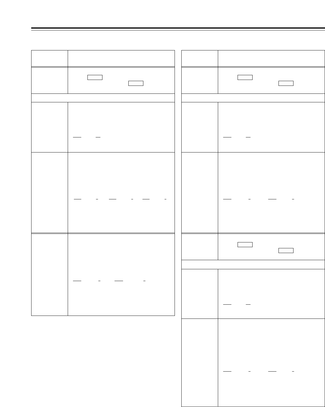
00
COARSE
For adjusting the VIDEO OUT system phase in 1H
steps.
j: To advance the phase. i: To delay the phase.
0000 j5H
::
0005 0H
::
0010 5H
<Note>
This setting remains unchanged
even when the factory setting
operation is performed.
No./Item Description of setting
12
SYS H
(HD)*UP
For adjusting the system phase of the HD SDI output.
When the button is pressed, the display transfers to
the submenu screen; press the button again to
return the display from the submenu screen.
SHIFT
SHIFT
00
COARSE
For adjusting the system phase of the HD SDI
output in 1H steps.
j: To advance the phase. i: To delay the phase.
0000 j5H
::
0005 0H
::
0010 5H
<Note>
This setting remains unchanged
even when the factory setting
operation is performed.
01
FINE
For adjusting the HD SDI output system
phase in 13.5ns steps.
j: To advance the phase. i: To delay the phase.
<59/60Hz> <23/24Hz> <50Hz, 25Hz (HD,SD)>
0000 j1100 0000 j1375 0000 j1320
:: ::::
1100 01375 01320 0
:: ::::
2200 1100 2700 1375 2640 1320
<Note>
This setting remains unchanged even when the
factory setting operation is performed.
Submenu screen
79
01
FINE
For adjusting the SD SDI system phase in 37ns
steps for 480i outputs and in 54ns steps for 480p
outputs.
j: To advance the phase. i: To delay the phase.
<59/60Hz, 23/24Hz> <50Hz, 25Hz (HD, SD)>
0000 j858 0000 j864
:: ::
0858 00864 0
:: ::
1716 858 1728 864
System menus
No./Item Description of setting
15
VO SYS
H (SD)*DW
For adjusting the system phase of the VIDEO OUT.
When the button is pressed, the display transfers to
the submenu screen; press the button again to
return the display from the submenu screen.
SHIFT
SHIFT
01
FINE
For adjusting the VIDEO OUT system phase in
37ns steps.
j: To advance the phase. i: To delay the phase.
<59/60Hz, 23/24Hz> <50Hz, 25Hz (HD, SD)>
0000 j858 0000 j864
:: ::
0858 00864 0
:: ::
1716 858 1728 864
16
SD SYS
H (SD)*DW
For adjusting the system phase of the SD SDI.
When the button is pressed, the display transfers to
the submenu screen; press the button again to
return the display from the submenu screen.
SHIFT
SHIFT
Submenu screen
The underlining (__) denotes the factory setting mode.
*UP: This is for HD outputs (during HD tape playback or up-
conversion outputs).
*DW:This is for SD outputs (during SD tape playback or down-
conversion outputs).
00
COARSE
For adjusting the SD SDI system phase in 1H
steps.
j: To advance the phase. i: To delay the phase.
0000 j5H
::
0005 0H
::
0010 5H
Submenu screen
<Note>
This setting remains unchanged
even when the factory setting
operation is performed.
14
SYS SC
(SD)*DW
For adjusting the system phase over a total
variable range of more than d180o.
j: To advance the phase. i: To delay the phase.
<59/60Hz, 23/24Hz> <50Hz, 25Hz (HD, SD)
0000 j108 0000 j115
:: ::
0108 00115 0
:: ::
0216 108 0230 115
<Note>
This setting remains unchanged even when the
factory setting operation is performed.
<Note>
This setting remains unchanged even when the
factory setting operation is performed.
<Note>
This setting remains unchanged even when the
factory setting operation is performed.
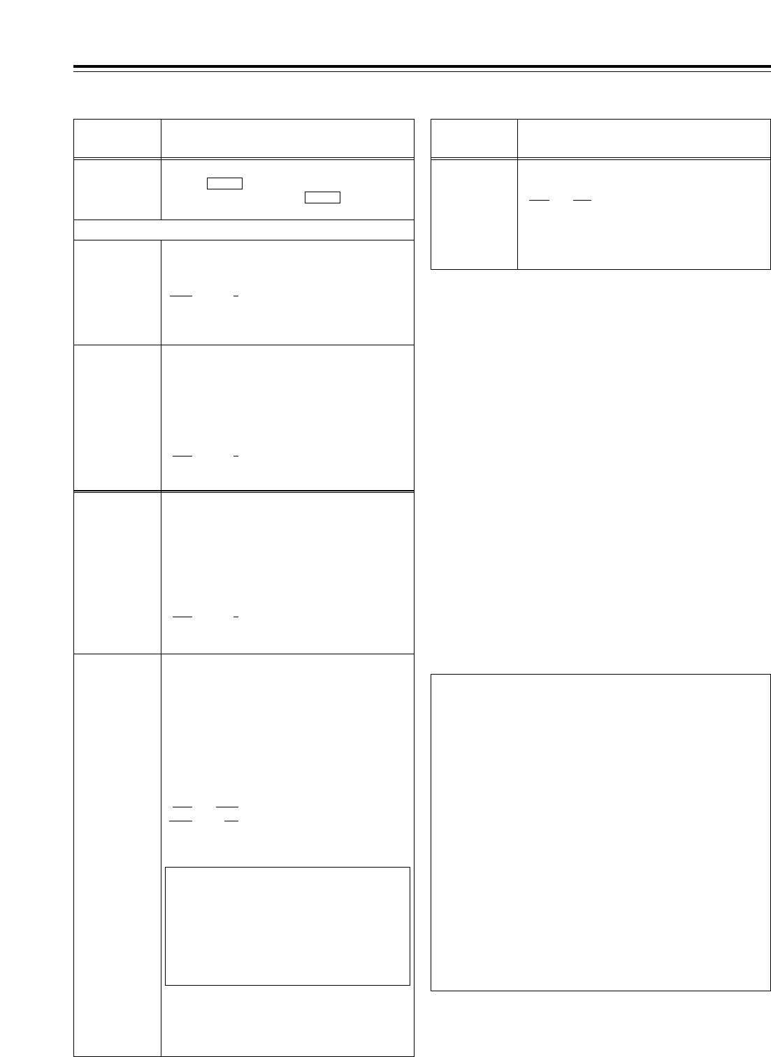
59/60 Hz mode: Status in which “0” (59/60) has been
selected
50 Hz mode: Status in which “1” (50) has been
selected
23/24 Hz mode: Status in which “2” (23/24) has been
selected
25 Hz (HD) mode: Status in which “3” (25 (HD)) has been
selected
25 Hz (SD) mode: Status in which “4” (25(SD)) has been
selected
80
System menus
*System switching
• Some of the system menu and setup menu items each have
different settings for different operation modes (59/60 Hz, 50
Hz, 23/24 Hz and 25 Hz (HD or SD)). These settings are
saved separately.
(This concerns those items whose settings were described
for each operation mode on the system menu and setup
menu tables.)
• For further details, refer to “How to switch the system
frequency” on page 105.
• Since this VTR becomes a playback-only unit when the
23/24 Hz or 25 Hz (HD or SD) mode has been selected,
the functions relating to EE, recording and editing are all
set to the inhibited status. Neither is it possible to select
CTL in such a case.
(The related menus and function buttons are not
displayed, and operation is prohibited.)
For the instant when the tape begins to run at the 1k
speed such as when it starts playing from the STOP
status, the image is disrupted and the sound is muted for
several frames because the tape is being synchronized
with the REF input.
The underlining (__) denotes the factory setting mode.
*DW:This is for SD outputs (during SD tape playback or down-
conversion outputs).
No./Item Description of setting
18
SCH (SD)*DW
For adjusting the SCH phase.
When the button is pressed, the display transfers to
the submenu screen; press the button again to
return the display from the submenu screen.
SHIFT
SHIFT
00
COARSE
For adjusting the SCH phase in 90
o
steps
(The SC phase changes, and the H phase remains
unchanged.)
0000: 0
0001: 90
0002: 180
0003: 270
Submenu screen
No./Item Description of setting
30
MENU LOCK
For selecting whether to set or release the
system file lock mode.
0000 OFF
:
Lock released (changes enabled)
0001 ON
:
Lock set (changes prohibited)
<Note>
Even when “ON” is selected, the data will be overwritten
when the system file has been set to LOAD from the IC
card.
<Notes>
• This setting remains unchanged even when the
factory setting operation is performed.
• For the steps to take to switch the system
frequency, refer to page 105.
25
SYSTEM
FREQ*
01
FINE
For adjusting the SCH phase over a total variable
range of more than d45
o
.
j: To advance the phase. i: To delay the phase.
(The SC phase changes, and the H phase remains
unchanged.)
0000 j32
::
0032 0
::
0064 32
20
AV PHASE
For adjusting the audio output phase in relation to
the video output phase in 20.8¨s steps.
j
:
The audio output phase is advanced in relation to
the video output phase.
i
:
The audio output phase is delayed in relation to
the video output phase.
0000 j100
::
0100 0
::
0200 100
For selecting the system frequency.
0: The 59.94 Hz or 60 Hz system frequency is selected.
1: The 50 Hz system frequency is selected.
2: The 23.98 Hz or 24 Hz system frequency is selected.
3: The 25 Hz system frequency is selected.
However, with SD SDI and video output signals, there
is a delay of approximately one field compared with
the HD SDI output.
4: The 25 Hz system frequency is selected.
However, HD SDI output is muted.
0003 59/60
0001* 50*
0002 23/24
0003 25 (HD)
0004 25 (SD)
* The asterisk denotes the
factory setting for AJ-
HD1700E
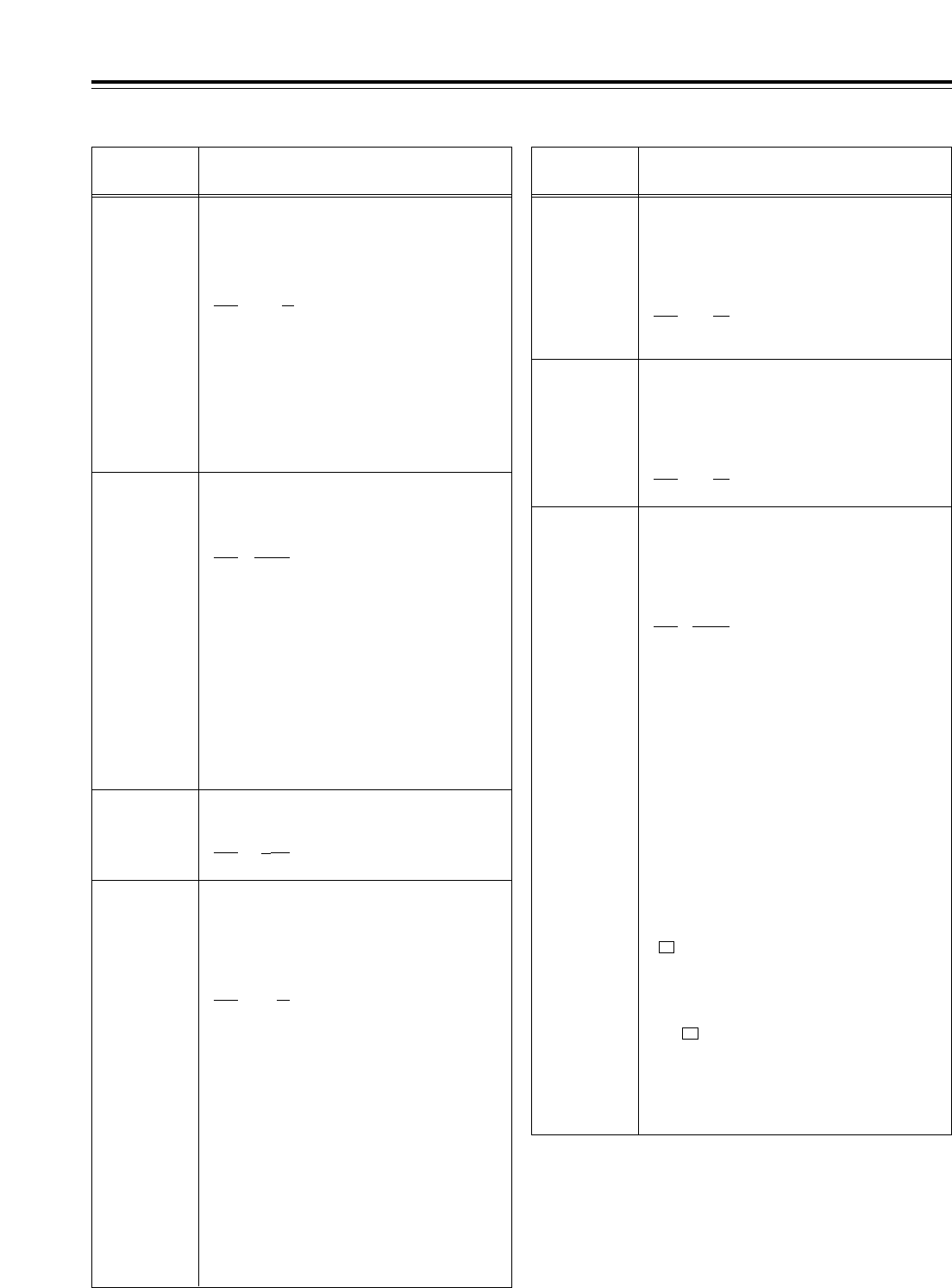
81
Setup menus
The underlining (__) denotes the factory setting mode.
<BASIC>
No./Item Description of setting
000
P-ROLL TIME
For setting the preroll time.
Any time from 0 to 30 seconds can be set in 1-
second increments.
0000 0s
::
0005 5s
::
0030 30s
<Notes>
•During automatic editing (PREVIEW or AUTO EDIT),
no operations are performed if the preroll time is set
to 0 seconds.
•If the phases are to be synchronized between two
decks for editing as per the setup menu item No.004
(SYNCHRONIZE) setting, set the preroll time to at
least 2 seconds.
001
LOCAL ENA
For selecting the transport system buttons
which can be operated on the front panel in
the REMOTE mode.
0000 DIS
:No buttons can be operated.
0001 ST&EJ
:
Only the STOP and EJECT buttons can be
operated.
0002 ENA
:
All the buttons except for the RECORDER and
PLAYER buttons can be operated.
<Note>
The following buttons and dials function at all times
regardless of this setting:
Audio input/output level control dials, audio channel
selector buttons, number keys, function buttons, direct
menu button, ASSEM button, INSERT button, ADJ dial,
headphone volume control dial, MONITOR SELECT
button, METER (FULL/FINE) selector switch, REMOTE
button.
002*1
TAPE TIMER
For selecting the 12- or 24-hour system for
the CTL counter display.
0000 d12h
:12-hour system display
0001 24h
:24-hour system display
005
SUPER
For selecting whether or not to superimpose
the display of the time code or other data
onto the HD SDI MONITOR, SD SDI MONITOR
and VIDEO OUT3 connectors.
0000 OFF
:
The time code or other data is not displayed.
0001 ON
:
The time code or other data is displayed.
003
REMAIN SEL
For selecting whether or not to display REMAIN
(remaining tape time) on the superimposed
display of the HD SDI MONITOR, SD SDI
MONITOR and VIDEO OUT3 connectors.
0000 OFF
:
The remaining tape time is not displayed.
0001 2L
:
The remaining tape time is displayed on the
second line.
0002 1L
:
The remaining tape time is displayed on the
first line.
0003 R/TTL
:
The remaining tape time is displayed on the
first line, and the total tape time is displayed on
the second line.
<Notes>
•When setting 1 (2L) has been selected, the remaining
tape time is not displayed if 0 (TIME) is selected as
the setup menu item No.006 (DISPLAY SEL) setting.
•When setting 3 (R/TTL) has been selected, the
remaining tape time is not displayed if 0 (TIME) is
selected as the setup menu item No.006 (DISPLAY
SEL) setting.
006
DISPLAY SEL
For selecting the time code and other
displays to be superimposed onto the HD SDI
MONITOR, SD SDI MONITOR and VIDEO
OUT3 connectors.
0000 TIME
:
Only the time is displayed.
0001 T&STA
:
The time and operation mode are displayed.
0002 T&S&M
:
The time, operation mode and mode are
displayed.
0003 T&RT
:
The time and REC TIME are displayed.
0004 T&YMD
:
The time and REC DATE (year/month/day) are
displayed.
0005 T&MDY
:
The time and REC DATE (month/day/year) are
displayed.
0006 T&DMY
:
The time and REC DATE (day/month/year) are
displayed.
0007 T&UB
:
Data and user’s bit are displayed.
However, when UB has been selected with the
(TC/CTL) on the HOME menu, the time
code is displayed after the user
’
s bit.
0008 T&CTL
:
Data and CTL data are displayed.
However, when CTL has been selected with
the (TC/CTL) on the HOME menu, the time
code is displayed after the CTL data.
0009 T&T
:
Data and time code are displayed.
(See Notes on next page.)
F3
F3
No./Item Description of setting
004*1
SYNCHRONIZE
For setting whether or not to synchronize the
phases between two decks.
0000 OFF
:
The phases are not synchronized. The edit
points will be off by several frames but editing
will be commenced more promptly.
0001 ON
:
The phases are synchronized. Error-free
editing can be performed.
*1: This item is not displayed when the 23/24 Hz or 25 Hz (HD or
SD) mode has been selected as the system menu item.

82
Setup menus
The underlining (__) denotes the factory setting mode.
<BASIC> (continued)
No./Item Description of setting No./Item Description of setting
008
CHARA
V-POS
For setting the vertical positions of the
characters for the time code and other
superimposed displays of the HD SDI
MONITOR, SD SDI MONITOR and VIDEO
OUT3 connectors.
0000 0
::
0023 23
::
0032 32
<Note>
When this menu item has been set, the displays are
output to the VIDEO OUT3 connector in the DISPLAY
SEL status even when the SUPER OFF setting is
established. However, if the menu has been exited, the
SUPER OFF or ON setting is followed.
Furthermore, CHARA TYPE is output to the VIDEO
OUT3 connector as per the menu setting.
007
CHARA
H-POS
For setting the horizontal positions of the
characters for the time code and other
superimposed displays of the HD SDI
MONITOR, SD SDI MONITOR and VIDEO
OUT3 connectors.
0000 0
::
0006 6
::
0037 37
<Note>
When this menu item has been set, the displays are
output to the VIDEO OUT3 connector in the DISPLAY
SEL status even when the SUPER OFF setting is
established. However, if the menu has been exited, the
SUPER OFF or ON setting is followed.
Furthermore, CHARA TYPE is output to the VIDEO
OUT3 connector as per the menu setting.
*1: This item is not displayed when the 23/24 Hz or 25 Hz (HD or
SD) mode has been selected as the system menu item No.25
(SYSTEM FREQ) setting.
*2: This item is not displayed when the 23/24 Hz, 25 Hz (HD or SD)
or 50 Hz mode has been selected as the system menu item
No.25 (SYSTEM FREQ) setting.
020*2
SYS
FORMAT
For selecting the VTR’s recording format.
0000 1080i
:
The 1080i format is selected.
0001 720p
:
The 720p format is selected.
015
AUTO
STEP
For selecting the save processing to be
conducted when the memory capacity, which
enables up to 99 warning messages to be
saved, has been exceeded while the error log
function is operating.
0000
OFF
:
99 messages are set as the upper limit, and any
more warning messages which subsequently
occur are not saved in the memory.
0001 ON
:
99 messages are saved, and the next warning
message that has subsequently occurred is
saved as No.99. The warning messages already
saved are each shifted down by one number in
succession.
011
CU-ROLL
TIME
For setting the preroll time in the MULTI CUE
mode.
Any time from 0 to 15 seconds can be set in 1-
second increments.
0000 0s
:
::
0005 5s
:
::
0015 15s
:
010*1
MONI
CONTROL
For setting whether to forcibly set the recorder to
the EE mode and output the player’s playback
signals to the monitor if the PLAYER button on the
recorder is pressed when the monitor is connected
only to the recorder during deck-to-deck editing.
0000 MANU
:
The recorder is not forcibly set to the EE mode.
0001 AUTO
:
The recorder is forcibly set to the EE mode,
and the player’s playback signals are output
.
006
DISPLAY SEL
<Notes>
•The following mode displays appear depending on
the format used.
<Format> <Display>
DVCPRO HD-LP >DVCPRO_HD-LP
DVCPRO HD >DVCPRO_HD
DVCPRO50 >DVCPRO_50
DVCPRO >DVCPRO
DV >DV
DVCAM >DVCAM
•When setting 2 (T&S&M) is selected, an error
message appears if a warning or error has occurred.
•REC TIME and REC DATE are displayed only during
DV or DVCAM format playback. The operation mode
is displayed when the DVCPRO HD-LP, DVCPRO
HD, DVCPRO50 or DVCPRO format is used.
009
CHARA TYPE
For setting the display type for the
superimposed displays and for the HD SDI
MONITOR, SD SDI MONITOR and VIDEO
OUT3 connectors as well as for the SETUP
MENU, etc.
0000 WHITE
:White characters on a black
background.
0001 W/OUT
:White characters with black
borders.
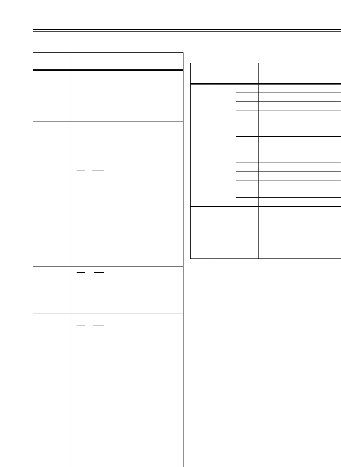
83
The underlining (__) denotes the factory setting mode.
Setup menus
<BASIC> (continued)
Formats in which the tape is played back
No./Item Description of setting
031*4
OUT REF
Video output reference
0000 AUTO
:
When the HD REF input signal is
supplied, it is used as the reference. If
it is not supplied but the SD REF input
signal is supplied, the SD REF signal
serves as the reference instead.
If neither the HD REF nor SD REF input
signal is supplied, the HD serial signal
serves as the reference.
If none of the HD REF, SD REF and
HD serial signals are supplied, the
internal sync signal serves as the
reference.
0001 INPUT
:
When the serial input signal is supplied,
it is used as the reference
.
0002 HD_REF
:
The signal which is input to the HD REF
IN connector is used as the reference.
0003 SD_REF
:
The signal which is input to the SD REF
IN connector is used as the reference.
<Note>
If the 1 (INPUT) setting is selected when the 25 Hz (HD)
mode has been selected as the system menu item
No.25 (SYSTEM FREQ) setting, the system will
construe this to mean that the 0 (AUTO) setting has
been selected.
AUTO
-------- --------
022:
PB
FORMAT
020:
SYS
FORMAT
023:
FORMAT
SEL
Playback format
MANUAL
1080i
720p
HD_LP
HD_SP
422
411
420p
DV
DVCAM
HD_LP
HD_SP
422
411
420p
DV
DVCAM
DVCPRO HD-LP(1080i)
DVCPRO HD(1080i)
DVCPRO50(422)
DVCPRO(411)
DVCPROP(420p)
DV
DVCAM
DVCPRO HD-LP(720p)
DVCPRO HD(720p)
DVCPRO50(422)
DVCPRO(411)
DVCPROP(420p)
DV
DVCAM
DVCPRO HD-LP(1080i)/
DVCPRO HD(1080i)/
DVCPRO HD-LP(720p)/
DVCPRO HD(720p)/
DVCPRO50(422)/
DVCPRO(411)/
DVCPROP(420p)/DV/
DVCAM, automatic detection
<Notes>
•In the EJECT mode, the format selected by the setup menu
item No.020 (SYS FORMAT) setting applies.
•If “AUTO” has been selected as the setup menu item No.022
(PB FORMAT) setting, the setup menu item No.023 (FORMAT
SEL) setting is used as the format when the format is not
detected (when the tape has just been inserted).
However, when “DV” or “DVCAM” has been selected, the VTR
operation will be as if “HD-LP” has been selected.
022
PB FORMAT
For selecting the format in which the tape is
to be played back.
0000 MANU
:
The format is determined by the setting selected for
setup menu item No.023 (FORMAT SEL).
0001 AUTO
:
The tape is played back in the format in which it was
recorded.
030*3
HD
FREQUENCY
0000 59/23
:
The 59.94/23.98 Hz frequency is set.
0001 60/24
:
The 60/24 Hz frequency is set.
However, the field frequency set here is used
only when there is no input signal which
corresponds to the OUT REF setting. If there is a
corresponding input signal, the field frequency is
matched with that of the input signal.
023
FORMAT
SEL
For selecting the format when “MANUAL” has
been selected as the setup menu item No.022
(PB FORMAT) setting.
If “AUTO” is selected as the setting, the format when
playback starts is selected, and when the tape is
played back, the format is automatically detected and
matched with the format of the playback tape.
0000 HD-LP
:The DVCPRO HD-LP format is
selected, and the setup menu
item No.020 (SYS FORMAT)
setting is followed.
0001 HD-SP
:The DVCPRO HD format is
selected, and the setup menu
item No.020 (SYS FORMAT)
setting is followed.
0002 422
:The DVCPRO50 (422) format is
selected.
0003 411
:The DVCPRO (411) format is
selected.
0004 420p
:The DVCPROP (420p) format
is selected.
0005 DV
:The DV format is selected.
0006 DVCAM
:The DVCAM format is selected.
*3: This item is not displayed when the 50 Hz or 25 Hz (HD or SD)
mode has been selected as the system menu item No.25
(SYSTEM FREQ) setting.
*4: This item is not displayed when the 23/24 Hz or 25 Hz (HD or
SD) mode has been selected as the system menu item No.25
(SYSTEM FREQ) setting.
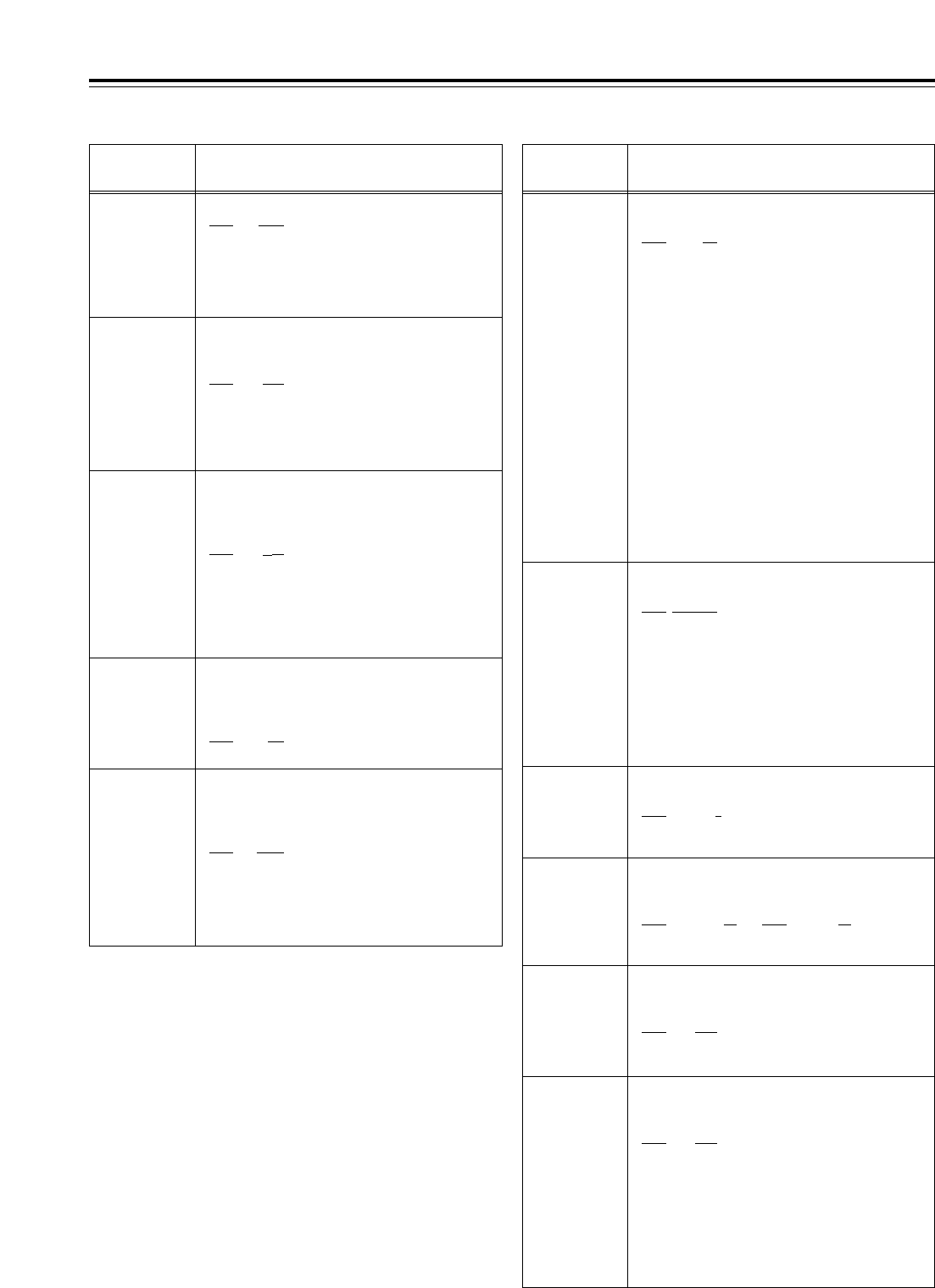
84
Setup menus
The underlining (__) denotes the factory setting mode.
<OPERATION>
No./Item Description of setting
100
SEARCH ENA
For selecting the direct search dial operation.
0000 DIAL
:
Direct search dial operations are performed.
0001 KEY
:
Operation does not transfer to the search
mode unless the SHTL, JOG or VAR button is
pressed.
101
SHTL MAX
For selecting the maximum speed of shuttle
operations.
0000 k9.8
:
k
9.8 times normal speed
0001 k16
:
k
16 times normal speed
0002 k32
:
k
32 times normal speed
<Note>
Depending on the tape format, the actual tape running
speed differs slightly from what is indicated by the
superimposed display.
102
FF. REW MAX
For setting the maximum speed of fast
forward and rewind operations.
0000 k16
:
k
16 times normal speed
0001 k32
:
k
32 times normal speed
0002 k50
:
k
50 times normal speed
0003 k60
:
k
60 times normal speed
0004 k100
:
k
100 times normal speed
<Note>
The maximum speed is automatically limited to 50x for
the DVCPRO HD and DVCPRO50 format and to 32x for
the DV and DVCAM formats.
104
REF ALARM
For selecting whether a warning is to be
displayed when the REF VIDEO signal has not
been connected.
0000 OFF
:A warning is not displayed.
0001 ON
:A warning is displayed by the
blinking STOP lamp.
105*1
AUTO EE SEL
For selecting the VTR mode which is to be set
to the EE mode when “0 (EE)” is selected as
the setup menu item No.140 (OUTPUT)
setting.
0000 S/F/R
:
The EE mode is established when the VTR is
in the STOP, FF or REW mode.
0001 STOP
:
The EE mode is established when the VTR is
in the STOP mode only.
106
EJECT EE SEL
For selecting the video and audio output
statuses in the EJECT mode.
0000
EE
:
The EE mode is always established regardless of
the setup menu item No.140 (OUTPUT) setting.
0001 BLACK
:
When setup menu item No.140 (OUTPUT) is set to:
“EE”
:
The EE mode is established.
“
TAPE”
:
The BLACK mode is established for
the video signals, and the audio
signals are muted.
0002 GRAY
:
When setup menu item No.140 (OUTPUT) is set to:
“EE”
:
The EE mode is established.
“
TAPE”
:
The GRAY mode is established for the
video signals, and the audio signals
are muted.
<Note>
If 0 (EE) is selected while the 23/24 Hz or 25 Hz (HD or
SD) mode has been selected as the system menu item
No.25 (SYSTEM FREQ) setting, the VTR construes that
1 (BLACK) has been selected.
107*1
EE MODE SEL
For selecting what signals are to be output
when the EE mode is established.
0000
NORMAL
:
Signals delayed by an amount equivalent to the time taken
for the signals to be processed internally are output.
0001 THRU
:
The signals are not processed internally but output in their
original form with no delay.
<Note>
The internal operation forcibly sets “NORMAL” when an
editing mode is selected or when SDTI is selected
during video input signal selection.
111*1
MEMORY
STOP
For selecting whether to automatically stop the
VTR when the counter value is at the “0” position
during CTL mode FF and REW operations.
0000 OFF
:
The VTR does not stop.
0001 ON
:
The VTR is automatically stopped.
<Notes>
•Either the stop or still picture (SHTL STILL or VAR
STILL) mode, whichever has been set using setup
menu item No.307 (AFTER CUE-UP), is
established when the VTR is stopped.
•If both the AUTO REW function and MEMORY
function have been selected at the same time, the
AUTO REW operation takes priority.
110
AUTO REW
For selecting whether the tape is to be
automatically wound back to its beginning
when the tape-end has been detected.
0000 OFF
:
The tape stops when it reaches the
tape-end.
0001 ON
:
The tape is rewound to its beginning.
109*1
CAP. LOCK
For selecting whether to engage playback framing
lock in 4-field increments or in 2-field increments.
<59/60Hz> <50Hz>
0000 2F 0000 2F
0001 4F 0001 4F
0002 8F
108
PLAY DELAY
For setting the play startup time in 1-frame
increments.
0000 0
::
0015 15
No./Item Description of setting
*1: This item is not displayed when the 23/24 Hz or 25 Hz (HD or
SD) mode has been selected as the system menu item No.25
(SYSTEM FREQ) setting.
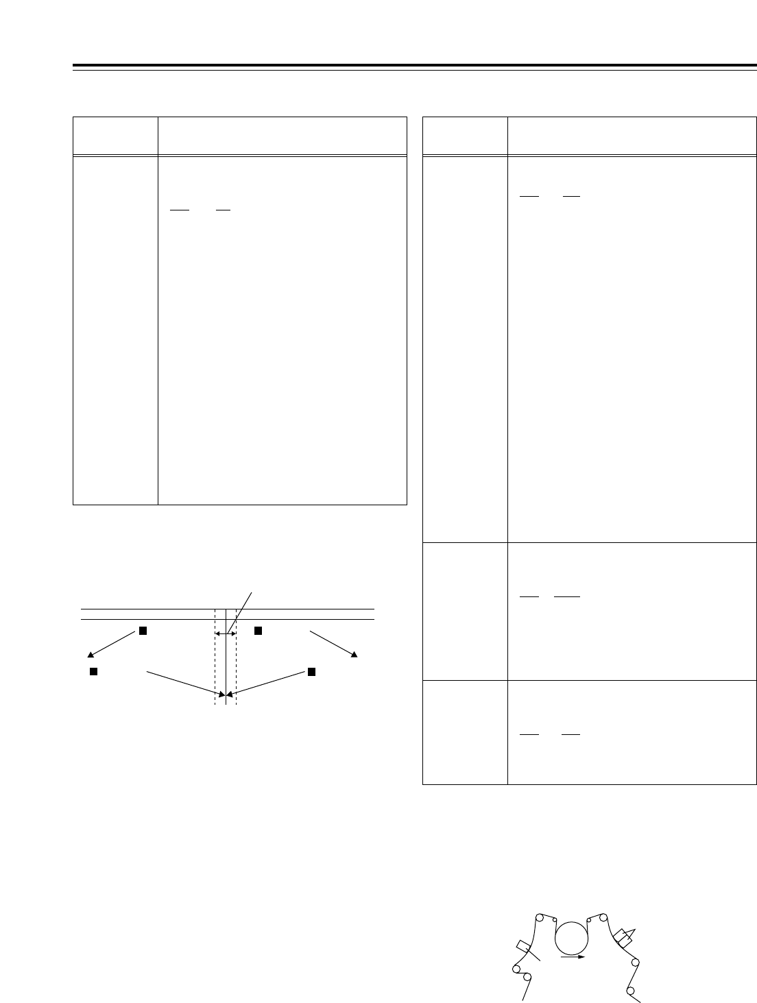
85
Setup menus
The underlining (__) denotes the factory setting mode.
<OPERATION> (continued)
113*1
REC INH
For selecting whether to allow or inhibit recording
on the cassette tape.
0000 OFF
:
Recording on the cassette tape is enabled when the
cassette’s accidental erasure prevention mechanism
has been set to the recording enable position.
0001 ALL
:
All recording on the cassette tape is inhibited.
0002 PRE
:
Overwriting is inhibited during normal recording.
This is the setting to activate the accidental erasure
prevention function. While CTL is detected, the
recording is inhibited, and when CTL cannot be
detected, it is executed.
0003 NORM
:
Normal recording is inhibited.
Use this setting when it is preferable to avoid
using normal recording in all applications
except for editing.
0004 V/CTL
:
The recording of the video and CTL signals is
inhibited.
Use this setting when it is preferable to avoid editing
in all applications except for audio editing
.
<Note>
When the PRE, NORM or V/CTL setting has been
selected, the REC INHIBIT lamp blinks (on for approx.
0.5 sec. and then off for approx. 0.5 sec.).
No./Item Description of setting
1
2
3
4
Description of MEMORY STOP function
The MEMORY STOP function does
not work if this margin is less than
d2 frames.
FF
button
0 point
FF
button
REW
button
REW
button
!If the FF button is pressed, the normal FF operation is performed
since there is no 0 point in the direction of this operation.
@If the REW button is pressed, the PREROLL lamp lights (as does
the SHTL lamp), the VTR prerolls the tape, and it automatically
stops when the counter value is at the 0 position.
#If the REW button is pressed, the normal REW operation is
performed since there is no 0 point in the direction of this
operation.
$If the FF button is pressed, the PREROLL lamp lights (as does
the SHTL lamp), the VTR prerolls the tape, and it automatically
stops when the counter value is at the 0 position.
114
REC INH
LAMP
For selecting whether the REC INHIBIT lamp is to
blink or light when the cassette tape has been set
to the accidental erasure protection mode.
0000 LIGHT
:The lamp lights.
0001 FLASH
:The lamp blinks.
<Note>
If 1 (ALL) has been selected as the setup menu item
No.113 (REC INH) setting, the REC INHIBIT lamp will
be lighted at all times regardless of the REC INH LAMP
setting.
115*1
EJECT SW
INH
For selecting whether to enable or disable the
operation of the EJECT button on the VTR’s
front panel.
0000 REC
:Operation is disabled while the
VTR is in the recording mode.
0001 OFF
:Operation is enabled in all
modes.
Accidental erasure protection function
This function is used to prevent parts already recorded on a tape from being
recorded over. Accidental erasure of pre-recorded tapes is prevented by
positioning the CTL signal rec/play heads as shown in the figure below so that
whether a recording has been made can be determined by the presence or
absence of the CTL signal. When the REC/PLAY button is pressed with a pre-
recorded tape, the tape runs but the REC button lamp blinks, the beeping
alarm is sounded, and no signals are recorded.
Rough sketch showing CTL head positions
PRE CTL
head
A/C heads
(rec/play heads)
*1: This item is not displayed when the 23/24 Hz or 25 Hz (HD or
SD) mode has been selected as the system menu item No.25
(SYSTEM FREQ) setting.
No./Item Description of setting
112
FRZ MODE
SEL
For selecting what playback images are to be
output in the STANDBY OFF mode and EJECT
mode.
0000 DIS
:
The video output is muted.
0001 STB OFF
:
Only when the STANDBY OFF mode is
established is the image which was being
played back at that moment frozen and output.
0002 SOF&EJ
:
When either the STANDBY OFF mode or the
EJECT mode is established, the image which
was being played back at that moment is
frozen and output.
<Notes>
•The status when the picture is frozen is determined
by the setup menu item No.604 (FREEZE SEL)
setting.
•In the EJECT mode, the frozen picture is output only
when 1 (BLACK) or 2 (GRAY) has been selected as
the setup menu item No.106 (EJECT EE SEL)
setting.
•The picture freeze is forcibly released if a change has
occurred in the output format of the HD serial output
signals when operation has transferred to the EJECT
mode.

86
Setup menus
The underlining (__) denotes the factory setting mode.
<OPERATION> (continued)
No./Item Description of setting
118*1
SP MODE
INH
For selecting whether to allow or inhibit
recording on a tape which has been written
by a format other than DVCPRO HD-LP.
0000 OFF
:
Recording on the cassette tape is allowed.
0001 ON
:
Recording on the cassette tape is inhibited.
<Notes>
•When 0 (OFF) has been selected, whether recording
on the cassette tape is allowed or inhibited is
determined by the setup menu item No.113 (REC
INH) setting.
•The recording format is determined by the setup
menu item No.020 (SYS FORMAT) setting.
131
PAGE MODE
For selecting what cue point operation is to
be performed when the multi cue function has
been set to ON.
0000 MANU
:
Operation is confined within the selected page,
and 6 cue points can be registered.
0001 AUTO
:
When the page whose cue points are being
registered becomes full, operation is
automatically transferred to the next page, and
registration is continued. A total of 60 cue
points on up to 10 pages can be registered.
132
ROTA MODE
For selecting whether to perform the
registration operation if all the cue points
have already been registered when the multi
cue function has been set to ON
.
0000 OFF
:
No further cue points are registered.
0001 ON
:
The registration operation is continued. If “MANU”
has been selected as the setup menu item No.131
(PAGE MODE) setting, the next cue point is
registered at CUE¢1 on the page concerned; if
“AUTO” has been selected, it is registered at CUE01.
No./Item Description of setting
140*1
OUTPUT
For selecting the output signals.
0000 EE
:
<In the STOP mode>:
The input signals selected by setup menu items
No.600 (VIDEO IN SEL) and No.713 (CH1 IN SEL)
to No.724 (D IN SEL 78) are output.
<During recording or editing>:
The input signals selected by setup menu items
No.600 (VIDEO IN SEL) and No.713 (CH1 IN SEL)
to No.724 (D IN SEL 78) are output:
0001 TAPE
:
<In the STOP mode>
The signals played back from the tape are output.
<During recording or editing>:
The simultaneous playback signals are output.
<Note>
In order to select the output signals during recording or
editing, set setup menu item No.302 (CONFI EDIT).
141*1
VOLUME
For setting what is to be controlled by the
audio volume controls on the front panel.
0000 REC
:
The controls function as REC volume controls.
0001 PB
:
The controls function as PB volume controls.
0002 AUTO
:
Normally, the controls function as PB volume
controls. However, during recording or in the
EE/INPUT CHECK status, they automatically
function as REC volume controls.
142*1
AUDIO UNITY
For selecting the conditions under which the
AUDIO UNITY lamp on the front panel is to light.
0000 IN
:
The lamp lights when all the audio input levels
are set to the UNITY level.
0001 OUT
:
The lamp lights when all the audio output
levels are set to the UNITY level.
0002 IN/OUT
:
The lamp lights when all the audio input and
output levels are set to the UNITY level.
143
CASSTT
LIGHT
For setting whether the lighting of the tape
mechanism is to be set to ON or remain OFF.
0000 OFF
:
The mechanism does not light even when a
cassette is inserted.
0001 ON
:
The mechanism lights when a cassette is inserted.
144
TC INPUT
For switching the preset registration method
for the time code.
0000 NORMAL:
The time code is input starting with the left-
most digit.
0001 REV
:
The time code is input from the high-order digit
but is displayed from the right-most digit.
145
FRONT LCD
For selecting whether the LCD monitor display on
the front panel is to be turned on or off.
0000 OFF
:
The display is turned off.
0001 ON
:
The display is turned on or off in synchronization
with the screen saver operation for the time code
display area.
133
KEY BEEP
For setting the volume of the sound heard
when the keys are touched.
0000 OFF
0001 LOW
0002 HIGH
134
ALARM BEEP
For setting the volume of the alarm tone.
0000 OFF
0001 LOW
0002 HIGH
<Note>
If the fan motor has shut down, the alarm tone is sounded
at the HIGH volume level regardless of this setting.
*1: This item is not displayed when the 23/24 Hz or 25 Hz (HD or
SD) mode has been selected as the system menu item No.25
(SYSTEM FREQ) setting.
116
EJECT LAMP
For selecting whether the EJECT lamp is to remain
lighted or go off after the cassette tape has been
ejected.
0000 MODE1
:
The EJECT lamp remains lighted.
0001 MODE2
:
The EJECT lamp goes off.
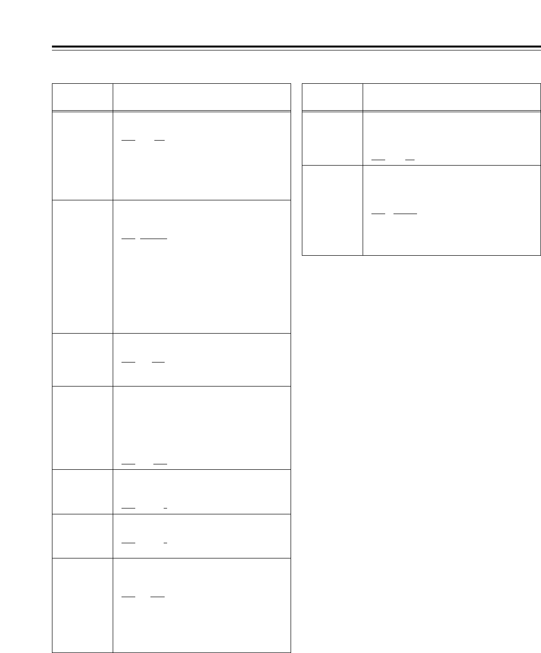
204
RS232C SEL
For selecting whether the RS-232C connector
is to function.
0000 OFF
:The RS-232C connector does
not function.
0001 ON
:
The RS-232C connector functions.
87
Setup menus
The underlining (__) denotes the factory setting mode.
<INTERFACE>
No./Item Description of setting
200
PARA RUN
For selecting whether to operate two or more
VTRs in synchronization.
0000 DIS
:The VTRs are not operated in
synchronization.
0001 ENA
:The VTRs are operated in
synchronization.
<Note>
To operate the VTRs in synchronization, set all the
VTRs to 1 (ENA). (Refer to pages 14 and 19.)
202
ID SEL
For setting what ID information is to be
returned to the controller.
0000 OTHER
0001 DVCPRO
0002 ORIG
<Notes>
• For 0 (OTHER), the ID information of VTRs other than
DVCPRO models is set.
• Select 2 (ORIG) only when the VTR is connected to a
Panasonic controller (such as the AJ-A900, an
optional accessory).
• Select 1 (DVCPRO) or 2 (ORIG) if the 23/24 Hz mode
has been selected by system menu item No.25
(SYSTEM FREQ).
205
BAUD RATE
For setting the RS-232C data transfer speed
(baud rate).
0000 300
0001 600
0002 1200
0003 2400
0004 4800
0005 9600
207
STOP BIT
For setting the number of RS-232C stop bits.
(Unit: bits)
0000 1
0001 2
206
DATA
LENGTH
For setting the RS-232C data length.
(Unit: bits)
0000 7
0001 8
208
PARITY
For setting whether the RS-232C parity bit is
to be used and, if it is used, whether even or
odd parity is to apply.
0000 NON
:
The parity bit is not used.
0001 ODD
:
The parity bit is used with an odd parity.
0002 EVEN
:
The parity bit is used with an even parity.
No./Item Description of setting
209
RETURN ACK
For setting whether or not to return the ACK
code when a command is received from RS-
232C.
0000 OFF
:The ACK code is not returned.
0001 ON
:The ACK code is returned.
212
MASTER
PORT
For selecting the remote control connector
for controlling the slave machine when this
VTR is to be used as the master machine for
deck-to-deck operations.
0001 IN/OUT
:The IN/OUT connector is used.
0001 OUT
:The OUT connector is used.
<Note>
This setting takes effect only when the 9P button has
been set to LOCAL (LED off).
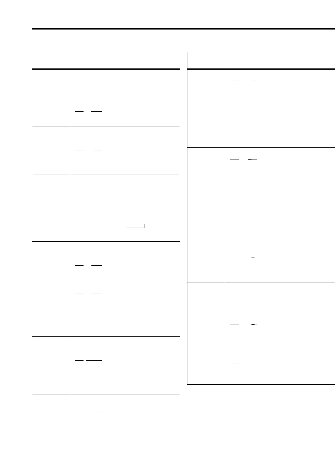
88
Setup menus
The underlining (__) denotes the factory setting mode.
<EDIT>
No./Item Description of setting
300
IN/OUT DEL
For selecting the operation to be performed when
an edit point has been set incorrectly (when the
OUT point comes before the IN point).
0000 MANU
:
Editing is not performed unless the illegal edit
point is cleared or set properly.
0001 AUTO
:
The edit point which had already been input is
cleared automatically.
301
NEGA FLASH
For selecting whether to show a negative display
(time code display area) when the IN point is
greater than the OUT point.
0000 OFF
:
A negative display is not shown.
0001 ON
:
A negative display is shown.
No./Item Description of setting
302
CONFI EDIT
For selecting whether to perform simultaneous
playback during editing.
0000 OFF
:Simultaneous playback is not
performed.
0001 ON
:Simultaneous playback is
performed.
<Note>
Simultaneous playback takes effect when TAPE is
selected as the F1 key setting on the
<HOME> menu. Refer to setup menu item No.140 as
well.
OUTPUT
303*1
AUD EDIT
IN
For selecting how to connect the digital audio
edit IN points.
0000 CUT
:Cut processing
0001 FADE
:V-fade processing
304*1
AUD EDIT
OUT
For selecting how to connect the digital audio
edit OUT points.
0000 CUT
:Cut processing
0001 FADE
:V-fade processing
305
AUTO ENTRY
For selecting whether to register the IN points
using the PREROLL button in cases where
the IN points have not been registered.
0000 DIS
:The IN points are not
registered.
0001 ENA
:The IN points are registered.
306*1
CF ADJ SEL
For selecting the deck whose the color
framing is to be adjusted during deck-to-deck
editing.
0000 PLAYER
:
The player’s IN and OUT points are adjusted
(using the recorder as the reference).
0001 RECORD
:
The recorder’s IN and OUT points are adjusted
(using the player as the reference).
307
AFTER
CUE-UP
For selecting the VTR’s mode upon
completion of the cue-up operation.
0000 STOP
:
The VTR is set to the STOP mode.
0001 STILL
:
The VTR is set to the still picture (SHTL STILL)
mode.
0002 STILL2
:
The VTR is set to the still picture (VAR STILL)
mode.
308
VAR FWD
MAX
For setting the maximum speed of VAR FWD.
0000
i
4.9
:i4.9 times normal tape speed
0001 i2
:i2 times normal tape speed
(i1.85 times normal tape
speed for formats other than
DVCPRO HD-LP)
0002 i1
:i1 times normal tape speed
<Notes>
•At any setting other than 0 (i4.9), phase adjustments
cannot be conducted from the editing controller.
•Depending on the format used, the actual tape
running speed differs slightly from what is indicated
by the superimposed display.
310
JOG FWD
MAX
For setting the maximum speed of JOG FWD.
0000 i4.9
:i4.9 times normal tape speed
0001 i2
:i2 times normal tape speed
(i1.85 times normal tape
speed for formats other than
DVCPRO HD-LP)
0002 i1
:i1 times normal tape speed
<Notes>
At any setting other than 0 (i4.9), phase adjustments
cannot be conducted from the editing controller which
performs these adjustments by the JOG command.
311
JOG REV MAX
For setting the maximum speed of JOG REV.
0000 j4.9
:j4.9 times normal tape speed
0001 j2
:j2 times normal tape speed
(j1.85 times normal tape
speed for formats other than
DVCPRO HD-LP)
0002 j1
:j1 times normal tape speed
312
POSTROLL
TM
For setting the postroll time.
Any time from 0 to 5 seconds can be set in 1-
second increments.
0000 0s
0001 1s
0002 2s
0003 3s
0004 4s
0005 5s
309
VAR REV MAX
For setting the maximum speed of VAR REV.
0000 j4.9
:j4.9 times normal tape speed
0001 j2
:j2 times normal tape speed
(j1.85 times normal tape
speed for formats other than
DVCPRO HD-LP)
0002 j1
:j1 times normal tape speed
<Note>
Depending on the format used, the actual tape running
speed differs slightly from what is indicated by the
superimposed display
.
*1: This item is not displayed when the 23/24 Hz or 25 Hz (HD or
SD) mode has been selected as the system menu item No.25
(SYSTEM FREQ) setting.

89
Setup menus
The underlining (__) denotes the factory setting mode.
<EDIT> (continued)
No./Item Description of setting No./Item Description of setting
324*1
EDIT RPLCEC
As with setup menu item No.320, the VTR’s
CUE edit presets are set to ON or OFF
following the analog audio signals specified
by the editor or controller.
0000 N-DEF
:
Not set.
0001 CH1
:
The analog CH1 edit presets are followed.
0002 CH2
:
The analog CH2 edit presets are followed.
0003 CH1+2
:
The analog CH1 or CH2 edit presets are
followed.
320*1
EDIT RPLCE1
For setting the allocation of the channels for
the analog audio presets of a controller when
a controller without a function to control the
edit presets of the digital audio signals is
used to edit the digital audio signals of the
VTR.
The VTR’s CH1 edit presets are set to ON or
OFF following the analog audio signals specified
by the controller.
0000 N-DEF
:
Not set.
0001 CH1
:
The analog CH1 edit presets are followed.
0002 CH2
:
The analog CH2 edit presets are followed.
0003 CH1+2
:
The analog CH1 or CH2 edit presets are
followed.
321*1
EDIT RPLCE2
As with setup menu item No.320, the VTR’s
CH2 edit presets are set to ON or OFF
following the analog audio signals specified
by the controller.
0000 N-DEF
:
Not set.
0001 CH1
:
The analog CH1 edit presets are followed.
0002 CH2
:
The analog CH2 edit presets are followed
0003 CH1+2
:
The analog CH1 or CH2 edit presets are
followed.
322*1
EDIT RPLCE3
As with setup menu item No.320, the VTR’s
CH3 edit presets are set to ON or OFF
following the analog audio signals specified
by the controller.
0000 N-DEF
:
Not set.
0001 CH1
:
The analog CH1 edit presets are followed.
0002 CH2
:
The analog CH2 edit presets are followed
0003 CH1+2
:
The analog CH1 or CH2 edit presets are
followed.
323*1
EDIT RPLCE4
As with setup menu item No.320, the VTR’s
CH4 edit presets are set to ON or OFF
following the analog audio signals specified
by the controller.
0000 N-DEF
:
Not set.
0001 CH1
:
The analog CH1 edit presets are followed.
0002 CH2
:
The analog CH2 edit presets are followed.
0003 CH1+2
:
The analog CH1 or CH2 edit presets are
followed.
*1: This item is not displayed when the 23/24 Hz or 25 Hz (HD or
SD) mode has been selected as the system menu item No.25
(SYSTEM FREQ) setting.
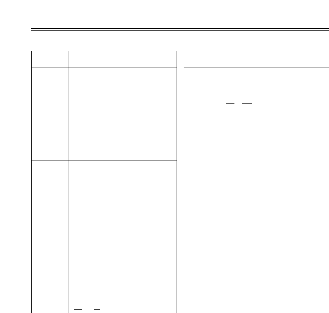
90
Setup menus
The underlining (__) denotes the factory setting mode.
<Precaution for STILL TIMER item setting>
The cumulative total standby time passed in the same location
increases at such times when the same material is repeatedly used
as is the case when programs are transmitted, for example.
<TAPE PROTECT>
No./Item Description of setting No./Item Description of setting
401
SRC
PROTECT
For selecting the operation to be performed
when the tape protection mode is established
after the VTR has been left standing in the
STILL status in a search mode (JOG, VAR or
SHTL).
0000 STEP
:STEP FWD
0001 HALF
:Half-loading
0002 T-REL
:Tension release
<Notes>
•When STEP FWD is selected, the VTR is
automatically transferred to the standby OFF (half-
loading) mode after it has been left standing in the
STILL status for a total of 30 minutes (or 1 minute in
the case of a DV or DVCAM tape).
•When, after tension release has been selected and
the VTR has been transferred to the tension release
mode, the VTR has been left standing in this mode
for a total of 2 hours, it is automatically transferred to
the standby OFF (half-loading) mode. However, in
the case of a DV or DVCAM tape, the transfer to the
tension release mode is inhibited, and the VTR
operates as if STEP FWD has been selected.
402
DRUM STDBY
For selecting whether the drum is to operate
in the standby OFF (half-loading) mode.
0000 OFF
:The drum stops rotating.
0001 ON
:The drum continues to rotate.
403
STOP
PROTECT
For selecting the operation to be performed
when the tape protection mode is established
after the VTR has been left standing in the
STOP mode.
0000 STEP
:STEP FWD
0001 HALF
:Half-loading
0002 T-REL
:Tension release
<Notes>
•When STEP FWD is selected, the VTR is
automatically transferred to the standby OFF (half-
loading) mode after it has been left standing in the
STOP mode for a total of 30 minutes (or 1 minute in
the case of a DV or DVCAM tape).
•When, after tension release has been selected and
the VTR has been transferred to the tension release
mode, the VTR has been left standing in this mode
for a total of 2 hours, it is automatically transferred to
the standby OFF (half-loading) mode. However, in
the case of a DV or DVCAM tape, the transfer to the
tension release mode is inhibited, and the VTR
operates as if STEP FWD has been selected.
400
STILL TIMER
For selecting the duration of the time taken
after the VTR is left standing in the STOP or
search STILL mode (JOG, VAR or SHTL)
before the tape protection mode is
established.
(Units: s = seconds, min = minutes)
0000 0.5s
0001 5s
0002 10s
0003 20s
0004 30s
0005 40s
0006 50s
0007 1min
0008 2min
<Note>
When a DV or DVCAM tape is
used, the time is set to 10
seconds even when a setting of
2 (10s) or longer is selected.
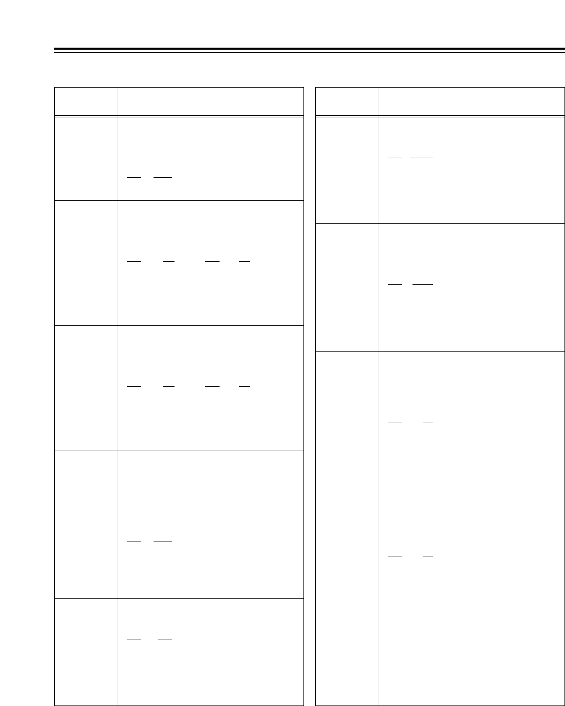
91
Setup menus
The underlining (__) denotes the factory setting mode.
<TIME CODE>
No./Item Description of setting
500*4
VITC BLANK
For selecting whether or not to output the
VITC signal at the positions selected by setup
menu items No.501 (VITC POS-1) and No.502
(VITC POS-2).
0000 BLANK
:The VITC signal is not output.
0001 THRU
:The VITC signal is output.
<Note>
Only the SD output takes effect at this setting.
501*4
VITC POS-1
For setting the position where the VITC signal
is to be inserted.
<59/60Hz> <50Hz, 25Hz (SD)>
0000 10L 0000 7L
:: ::
0006 16L 0004 11L
:: ::
0010 20L 0015 22L
<Notes>
• The same line as the one selected by the setup menu
item No.502 (VITC POS-2) cannot be selected.
• Only the SD output takes effect at this setting.
505*1
TCG REGEN
For selecting the regeneration signal when
REGEN has been selected as the TCG (time
code generator) mode.
0000 TC&UB
:
Regeneration applies to both the time code
and user’s bit.
0001 TC
:
Regeneration applies only to the time code only.
0002 UB
:
Regeneration applies only to the user’s bit only.
506*1
REGEN MODE
For selecting the editing mode range when
the VTR is operating in the REGEN mode
while performing editing operations with
“AUTO” selected as the setup menu item
No.503 (TCG MODE) setting.
0000 AS&IN
:
Regeneration applies during assemble or
insert editing.
0001 ASSEM
:
Regeneration applies during assemble editing.
0002 INSRT
:
Regeneration applies during insert editing.
507*1
TC SOURCE
For selecting the time code to be used when
HD SDI or SD SDI has been selected as the
setup menu item No.600 (VIDEO IN SEL)
setting when an external time code is to be
used.
[When HD SDI has been selected]
0000 INT
:
The time code of the internal time code
generator is used.
0001 EXT_L
:
LTC of the TIME CODE IN connector is used.
0002 SLTC
:
The LTC information added to the serial
signals which are input to HD SDI IN is used.
0003 SVITC
:
The VITC information added to the serial
signals which are input to HD SDI IN is used.
[When SD SDI has been selected]
0000 INT
:
The time code of the internal time code
generator is used.
0001 EXT_L
:
LTC of the TIME CODE IN connector is used.
0002 VITC
:
The VITC information added to the serial
signals which are input to SD SDI IN is used.
<Note>
If the VIDEO IN SEL input selection is changed, the time
code is converted as shown below.
[HD_SDI] [SD_SDI]
INT ↔INT
EXT_L ↔EXT_L
SLTC ↔EXT_L
SVITC ↔VITC
502*4
VITC POS-2
For setting the position where the VITC signal
is to be inserted.
<59/60Hz> <50Hz, 25Hz (SD)>
0000 10L 0000 7L
:: ::
0008 18L 0006 13L
:: ::
0010 20L 0015 22L
<Notes>
• The same line as the one selected by the setup menu
item No.501 (VITC POS-1) cannot be selected.
• Only the SD output takes effect at this setting.
503*1
TCG MODE
For setting the synchronization of the internal
time code generator.
0000 REGEN
:
The time code reader is synchronized with the
time code which is read from the tape.
0001 PRE
:
Presetting is enabled at the operation panel or
by the remote controller.
0002 AUTO
:
The REGEN and PRE settings are
automatically switched in accordance with the
operation mode.
In the editing mode: REGEN is selected.
In all other modes: PRE is selected.
504*1
RUN MODE
For setting when the internal time code
generator is to advance depending on the
operation mode.
0000 REC
:
The time code generator is advanced during
recording.
0001 FREE
:
The time code generator is advanced while the
power is on regardless of which operation
mode is established.
No./Item Description of setting
*1: This item is not displayed when the 23/24 Hz or 25 Hz (HD or SD) mode
has been selected as the system menu item No.25 (SYSTEM FREQ)
setting.
*2: This item is not displayed when the 23/24 Hz or 25 Hz (HD) mode has
been selected as the system menu item No.25 (SYSTEM FREQ) setting.

92
513
VITC OUT
For selecting how to output the VITC which is
superimposed on the output video signal.
0000 SBC
:
In the playback mode, the time code recorded
in the SBC area is output.
0001 VAUX
:
In the playback mode, the time code recorded
in the VAUX area is output.
<Note>
The VITC information detected by the HD serial input is
automatically recorded in the VAUX area when the video
signals are recorded
.
Setup menus
The underlining (__) denotes the factory setting mode.
<TIME CODE> (continued)
No./Item Description of setting
514
HD EMBD
VITC
For selecting whether to superimpose the
VITC information on the HD serial output.
0000 OFF
:
The VITC information is not superimposed.
0001 ON
:
The VITC information is superimposed.
515
HD EMBD LTC
For selecting whether to superimpose the
LTC information on the HD serial output.
0000 OFF
:
The LTC information is not superimposed.
0001 ON
:
The LTC information ist superimposed.
516*1
TC OUT ADV
For selecting the processing to align the
phase of the time code which is output from
the TIME CODE OUT connector.
Normally, the time code which is output from the
TIME CODE OUT connector is aligned with the
output video and audio. If so required by the
connection with an external component or for
some other reason, this item makes it possible to
set the mode for aligning the phase with the
input.
0000 OFF
:
The phase alignment processing is not
conducted. The time code which is output
from the TIME CODE OUT connector is
aligned with the output video and audio.
0001 EDIT
:
During playback when an editing mode has
been selected and during editing, the time
code which is output from the TIME CODE
OUT connector is aligned with the input video
and audio. In all other modes, it is aligned with
the output video and audio
.
517*1
TCG OUT
For selecting whether to latch the TCG
display and LTC output during INPUT CHECK.
0000 MOMENT
:
The INPUT CHECK mode is established only
while the INPUT CHECK key is held down.
0001 LATCH
:
When the INPUT CHECK key is pressed, the
INPUT CHECK mode is established; even
when it is released, the mode remains
unchanged. The selection is released when
the video output is set to a mode other than the
EE mode.
SBC (sub code data) area:
This is an area on the helical track, and it is separate from the video
and audio data area. The time codes, recording dates and times
and other tape control information complying with SMPTE/EBU
standards are stored here. As with the conventional LTC (linear time
code), the time code can be read even during rewinding or fast
forwarding. It can also be read out when the tape has stopped.
VAUX (video auxiliary data) area:
This area is to be found in the video data area on the helical track.
The additional information relating to the video data is stored here.
508*1
BINARY GP
For setting how the user’s bit of the time code
generated by the TCG is to be used.
0000 000
:
NOT SPECIFIED (no character set specified)
0001 001
:
ISO CHARACTER (8-bit character set
complying with ISO646, ISO2022 standards)
0002 010
:UNASSIGNED 1 (undefined)
0003 011
:UNASSIGNED 2 (undefined)
0004 100
:UNASSIGNED 3 (undefined)
0005 101
:PAGE/LINE
0006 110
:UNASSIGNED 4 (undefined)
0007 111
:UNASSIGNED 5 (undefined)
509
PHASE CORR
For selecting whether to exercise phase
correction control over the LTC which is
generated by the TCG.
0000 OFF
:
Phase correction control is not exercised.
0001 ON
:
Phase correction control is exercised.
510*1
TCG CF FLAG
For selecting whether to set the CF flag of the
TCG to ON or OFF.
0000 OFF
:The CF flag is set to OFF.
0001 ON
:The CF flag is set to ON.
511*2
DF MODE
For selecting the drop frame or non-drop
frame mode for CTL and TCG.
0000 DF
:The drop frame mode is
selected.
0001 NDF
:The non-drop frame mode is
selected.
<Note>
This DF mode setting takes effect only when LOCAL is
selected or when “ENA” has been selected as the setup
menu item No.001 (LOCAL ENA) setting.
512*1
TC OUT REF
For switching the phase of the time code,
which is output from the TIME CODE OUT
connector, in response to the external LTC
input when a setting other than “INT” has
been selected for setup menu item No.507 (TC
SOURCE). (In EE mode only)
0000 VOUT
:The phase is aligned with the
output image.
0001 TC IN
:The phase is aligned with the
external time code input
.
No./Item Description of setting
*1: This item is not displayed when the 23/24 Hz or 25 Hz (HD or SD) mode
has been selected as the system menu item No.25 (SYSTEM FREQ)
setting.
*2: This item is not displayed when the 23/24 Hz, 25 Hz (HD or SD) or 50 Hz
mode has been selected as the system menu item No.25 (SYSTEM
FREQ) setting.
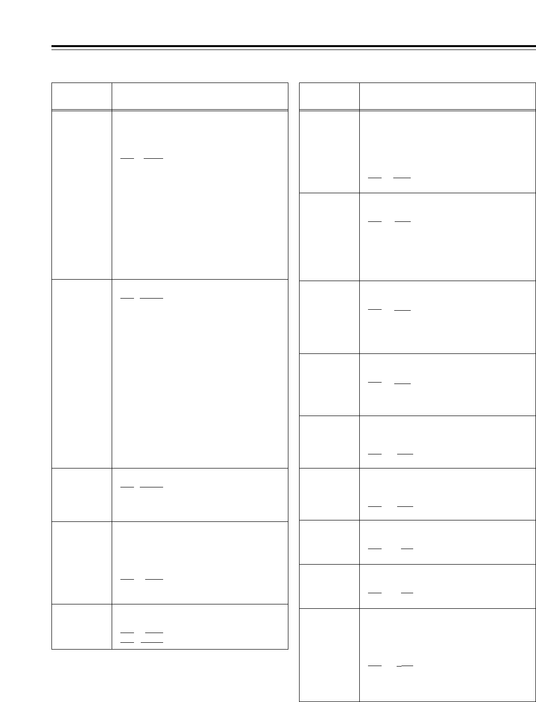
For accentuating the horizontal contours
during down-conversion and line conversion
(1080i <> 720p).
0000 0dB
0001 i0.7dB
0002 i1dB
0003 i1. 2dB
0004 i1.5dB
0005 i2dB
93
Setup menus
The underlining (__) denotes the factory setting mode.
<VIDEO>
No./Item Description of setting No./Item Description of setting
601*1
VIDEO INT SG
For selecting the type of internal signal.
0000
100%CB
:
A 100% color bar signal is selected.
0001 75
%
CB
:
A 75% color bar signal is selected.
0002 SMPTE
:
An SMPTE color bar signal is selected.
0003 ARIB
:
An ARIB color bar signal is selected.
0004 MB
:
A multiburst signal is selected.
0005 RAMP
:
A ramp signal is selected.
0006 BLACK
:
A black signal is selected.
0007 PLL
:
A PLL signal is selected.
0008 EQ
:
An EQ signal is selected.
600*1
VIDEO IN SEL
For selecting the video signal which is to be input.
0000 INT SG
:
The internal signal selected by the VIDEO INT
SG item is generated.
0001 HDSDI
:
The serial video signal which has been input to the
HD SDI IN connector is selected.
0002 SDTI
:(In 59/60 Hz mode)
The compressed IF signal which has been input to
the SDTI IN connector is selected. (This setting
does not appear when the AJ-YAC15P optional
board has not been installed.)
0002 SD SDI
:
The serial video signal which has been input to the
SD SDI IN connector is selected. (This setting does
not appear when the AJ-UC1700G optional board
has not been installed.)
602*1
SDI IN MODE
For selecting how to process the serial input.
0000 DR OFF
:
The 8 higher bits after rounding up
the 2 lowest bits are recorded.
0001 DR ON
:
The signal with 8 higher bits, obtained
by dynamic rounding, is recorded.
603
V-MUTE SEL
For selecting whether to mute the video output
signals if LOW RF has been detected during
playback.
0000 N MUTE
:The signals are not muted.
(They are frozen.)
0001 GRAY
:
The signals are muted with gray.
0002 BLACK
:
The signals are muted with black.
0003 NOISE
:
The signals are muted with noise.
606
SD MONI O
SEL
For selecting the SD SDI or MONITOR output
signal.
0000 MONI
:: The MONITOR signal is output.
0001 SDI
:The same video signal as the
one output from the SD SDI
OUT1 connector is output
<Note>
When 1 (SDI) is selected, the time code and other
information are not superimposed on the display.
604*1
FREEZE SEL
For selecting the freeze mode of the still
pictures and slow playback mode.
0000 FIELD
:Field freeze, field slow
0000 FRAME
:Frame freeze, frame slow
605*1
INTERPOLATE
During field slow playback, vertical interpolation is
conducted automatically to minimize the up/down
movement of the playback pictures. However, this
setting enables the interpolation operation to be
forcibly set to OFF.
0000 OFF
:
The interpolation is forcibly set to OFF.
0001 AUTO
:
During slow playback, the interpolation
is automatically set to ON.
620*4
DOWNCON
MODE
For selecting the picture frame during down-
conversion.
0000 FIT_V
:Side cut mode
0001 FIT_H
:Letter box mode
0002 FIT_HV
:Squeeze mode
0003 14:9
:Semi letter box 14:9
0004 13:9
:Semi letter box 13:9
621*5
UPCON MODE
For selecting the picture frame during up-
conversion.
0000 FIT_V
:Side panel mode
0001 FIT_H
:Top and bottom cut in vertical
direction
0002 FIT_HV
:Stretch mode
622
D/C RESP
H
For selecting the horizontal frequency band
during down-conversion and line conversion
(1080i <> 720p).
0000 WIDE
0001 STD
623
D/C RESP
V
For selecting the vertical frequency band
during down-conversion and line conversion
(1080i <> 720p).
0000 WIDE
0001 STD
624*5
U/C RESP
H
For selecting the horizontal frequency band
during up-conversion and line conversion.
0000 STD
0001
NARROW
625*5
U/C RESP
V
For selecting the vertical frequency band
during up-conversion and line conversion.
0000 STD
0001
NARROW
626
D/C ENH
H
<Note>
The numbers on the superimposed
display are approximations only.
*1: This item is not displayed when the 23/24 Hz or 25 Hz (HD or SD) mode
has been selected as the system menu item.
*4: This item is not displayed when the 23/24 Hz or 25 Hz (HD) mode has
been selected as the system menu item No.25 (SYSTEM FREQ) setting.
*5: This item is not displayed when the 25 Hz (HD or SD) mode has been
selected as the system menu item No.25 (SYSTEM FREQ) setting.
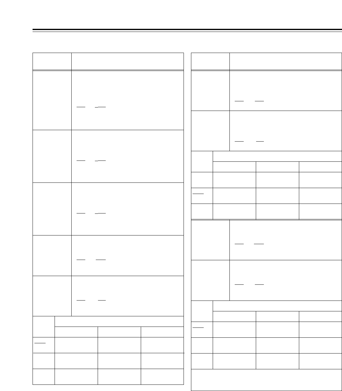
94
Setup menus
The underlining (__) denotes the factory setting mode.
<VIDEO> (continued)
No./Item Description of setting No./Item Description of setting
627
D/C ENH V
For accentuating the vertical contours during
down-conversion and line conversion
(1080i <> 720p).
0000 0dB
0001 i0.7dB
0002 i1dB
0003 i1.2dB
0004 i1.5dB
0005 i2dB
628*5
U/C ENH H
For accentuating the horizontal contours
during up-conversion.
0000 0dB
0001 i0.7dB
0002 i1dB
0003 i1.2dB
0004 i1.5dB
0005 i2dB
629*5
U/C ENH V
For accentuating the vertical contours during
up-conversion.
0000 0dB
0001 i0.7dB
0002 i1dB
0003 i1.2dB
0004 i1.5dB
0005 i2dB
630*2
1080i>HD_
OUT
For selecting the HD output signal format
during 1080i tape playback or in the 1080i EE
mode. (See table below.)
0000 1080i
0001 720p
0002 1080i
631*2
1080i>SD_
OUT
For selecting the SD output signal format
during 1080i tape playback or in the 1080i EE
mode. (See table below.)
0000 480i
0001 --------
0002 480p
0000 1080i
(no conversion)
480i (down-
converted output)
480i (down-
converted output)
720p (line-
converted output)
480i (down-
converted output)
480i (down-
converted output)
1080i
(no conversion)
480p* (down-
converted output)
480i (down-
converted output)
0001
0002
HD SDI OUT SD SDI OUT
Output connectors
VIDEO OUT
632*2
720p>HD_
OUT
For selecting the HD output signal format
during 720p tape playback or in the 720p EE
mode. (See table below.)
0000 1080i
0001 720p
0002 720p
634*2
480p>HD_
OUT
For selecting the HD output signal format
during 480p tape (DVCPRO50P) playback.
(See table below.)
0000 1080i
0001 720p
0002 ---------
635*2
480p>SD_
OUT
For selecting the SD output signal format
during 480p tape (DVCPRO50P) playback.
(See table below.)
0000 480p
0001 480p
0002 480i
633*2
720p>SD_
OUT
For selecting the SD output signal format
during 720p tape playback or in the 720p EE
mode. (See table below.)
0000 --------
0001 480i
0002 480p
0000 1080i (line-
converted output)
480i (down-
converted output)
480i (down-
converted output)
720p
(no conversion)
480i (down-
converted output)
480i (down-
converted output)
720p
(no conversion)
480p* (down-
converted output)
480i (down-
converted output)
0001
0002
HD SDI OUT SD SDI OUT
Output connectors
VIDEO OUT
0000 1080i (up-
converted output)
480p*
(no conversion)
480i (down-
converted output)
720p (up-
converted output)
480p*
(no conversion)
480i (down-
converted output)
Muted 480i (down-
converted output)
480i (down-
converted output)
0001
0002
<Note>
During SD tape playback, the VTR cannot be operated in the 60
Hz mode.
HD SDI OUT SD SDI OUT
Output connectors
VIDEO OUT
<Note>
The numbers on the superimposed
display are approximations only.
<Note>
The numbers on the superimposed
display are approximations only.
<Note>
There is no output in the 60 Hz
mode.
<Note>
The numbers on the superimposed
display are approximations only.
*1: This item is not displayed when the 23/24 Hz, 25 Hz (HD or SD)
or 50 Hz mode has been selected as the system menu item
No.25 (SYSTEM FREQ) setting.
*2:This item is not displayed when the 25 Hz (HD or SD) mode has
been selected as the system menu item No.25 (SYSTEM FREQ)
setting.
* Setup menu item No.107 and INPUT CHECK do not function,
and the same signal as this signal line is output.
<Note>
There is no output in the 60 Hz
mode.
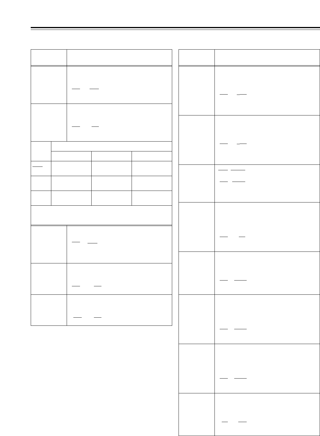
95
Setup menus
<Note>
Setup menu items No.638, 639, 640, 641 and 642 do not function
when the AJ-UC1700G optional board has not been installed.
The underlining (__) denotes the factory setting mode.
*UP: With HD output (HD tape playback or up-converted output)
*DW: With SD output (SD tape playback or down-converted output)
<VIDEO> (continued)
No./Item Description of setting No./Item Description of setting
637*2
480i>SD_
OUT
For selecting the SD output signal format
during 480i tape (DVCPRO50, DVCPRO, DV or
DVCAM) playback. (See table below.)
0000 480i
0001 480i
0002 480p
636*2
480i>HD_
OUT
For selecting the HD output signal format
during 480i tape (DVCPRO50, DVCPRO, DV or
DVCAM) playback. (See table below.)
0000 1080i
0001 720p
0002 ---------
0000 1080i (up-
converted output)
480i
(no conversion)
480i
(no conversion)
720p (up-
converted output)
480i
(no conversion)
480i
(no conversion)
Muted 480p* (up-
converted output)
480i
(no conversion)
0001
0002
HD SDI OUT SD SDI OUT
Output connectors
VIDEO OUT
638*1
IN U/C
MODE
For selecting the up-conversion picture frame
when SD SDI input signals are supplied.
0000 FIT_V
:Side panel mode
0001 FIT_H:
Top and bottom cut in vertical
direction
0002 FIT_HV
:
Stretch mode
639*1
I U/C RESP H
For selecting the horizontal frequency band
during the up-conversion of SD SDI input
signals.
0000 STD
0001 NARROW
640*1
I U/C RESP V
For selecting the vertical frequency band
during the up-conversion of SD SDI input
signals.
0000 STD
0001 NARROW
642*2
I U/C ENH
V
For accentuating the vertical contours during
up-conversion of SD SDI input signals.
0000 0dB
0001 i0.7dB
0002 i1dB
0003 i1.2dB
0004 i1.5dB
0005 i2dB
650
STYLE
0000* CMPNT*
:Level adjustment mode for the
component style
0001 CMPST
:Level adjustment mode for the
composite style
*The asterisk denotes the factory setting for
AJ-HD1700E.
For adjusting the black level of the HD SDI
output.
50 j10.0%
::
150 0.0%
::
250 i10.0%
<Note>
This setting takes effect when
“CMPNT” has been selected as the
setup menu item No.650 setting.
656
BK LVL
(HD)*UP
655
Pr LVL (HD)*UP
For adjusting the PB level of the HD SDI
output.
(j¶ to 0 dB to i3 dB)
0000 0.0%
::
1000 100.0%
::
1413 141.3%
651*3
HUE STYLE
(SD)*DW
For selecting the rotational axis of the chroma
phase adjustment.
0000 Pb-Pr
:The axis rotates in a perfect
circle on the SDI (component
style) vectorscope.
0001 U-V
:The axis rotates in a perfect
circle on the analog (composite
style) vectorscope.
653
Y LVL (HD)*UP
For adjusting the Y level of the HD SDI output.
(j¶ to 0 dB to i3 dB)
0000 0.0%
::
1000 100.0%
::
1413 141.3%
654
Pb LVL
(HD)*UP
For adjusting the PB level of the HD SDI
output.
(j¶ to 0 dB to i3 dB)
0000 0.0%
::
1000 100.0%
::
1413 141.3%
<Note>
This setting takes effect when
“CMPNT” has been selected as the
setup menu item No.650 setting.
<Note>
This setting takes effect when
“CMPNT” has been selected as the
setup menu item No.650 setting.
<Note>
This setting takes effect when
“CMPNT” has been selected as the
setup menu item No.650 setting.
<Note>
The numbers on the superimposed
display are approximations only.
<Note>
During SD tape playback, the VTR cannot be operated in the 60
Hz mode.
*1: This item is not displayed when the 23/24 Hz or 25 Hz (HD or
SD) mode has been selected as the system menu item No.25
(SYSTEM FREQ) setting.
*2: This item is not displayed when the 23/24 Hz, 25 Hz (HD or SD)
or 50 Hz mode has been selected as the system menu item
No.25 (SYSTEM FREQ) setting.
*3: This item is not displayed when the 50 Hz or 25 Hz (HD or SD)
mode has been selected as the system menu item No.25
(SYSTEM FREQ) setting.
* Setup menu item No.107 and INPUT CHECK do not function,
and the same signal as this signal line is output.
641*2
I U/C ENH
H
For accentuating the horizontal contours
during up-conversion of SD SDI input signals.
0000 0dB
0001 i0.7dB
0002 i1dB
0003 i1.2dB
0004 i1.5dB
0005 i2dB
<Note>
The numbers on the superimposed
display are approximations only.
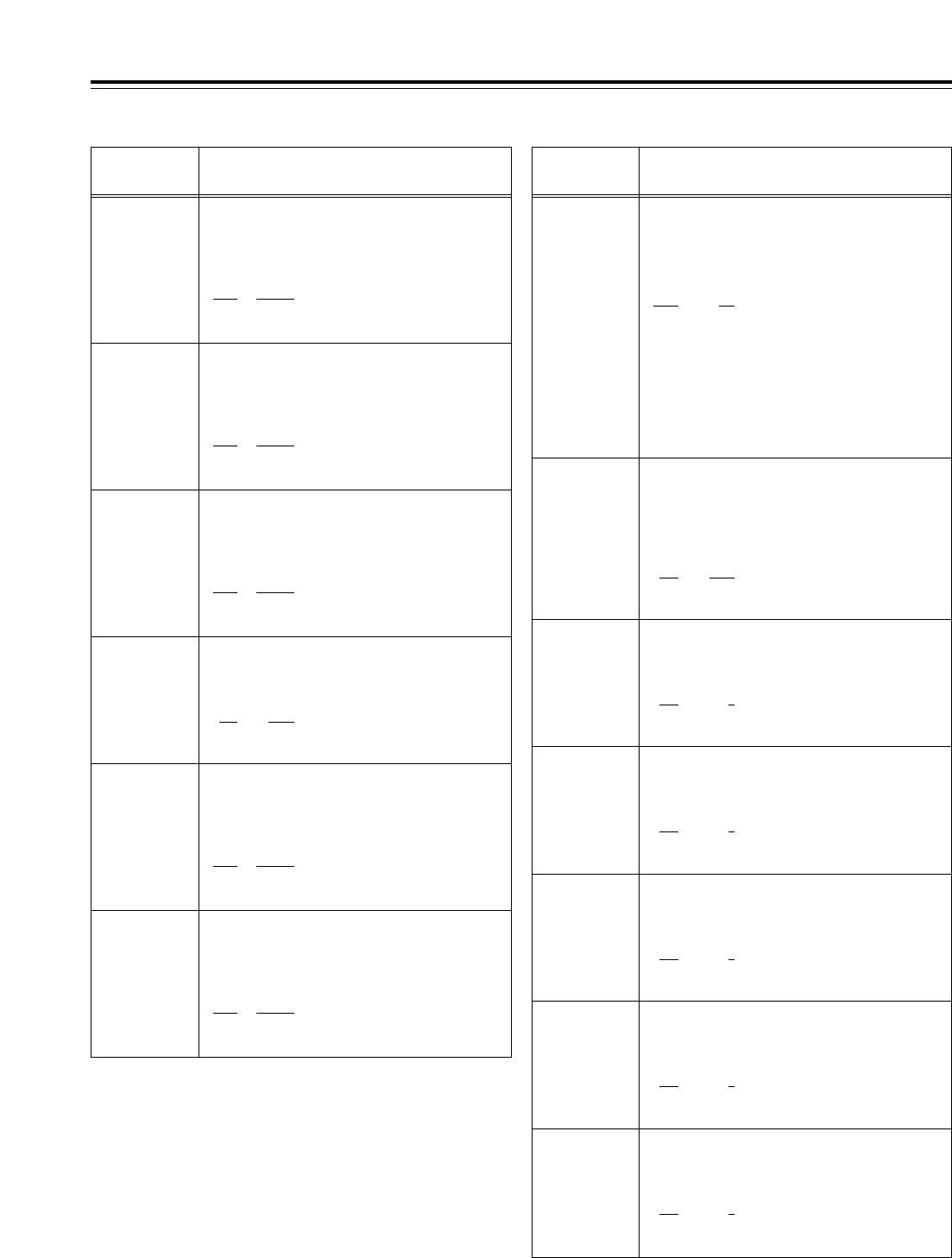
96
Setup menus
The underlining (__) denotes the factory setting mode.
*DW: With SD output (SD tape playback or down-converted
output)
<VIDEO> (continued)
No./Item Description of setting No./Item Description of setting
663
C LEVEL
For adjusting the chroma level of the HD SDI
output, SD SDI output and VIDEO output.
(j¶ to 0 dB to i3 dB)
0000 0.0%
::
1000 100.0%
::
1413 141.3%
660
Pr LVL
(SD)*DW
For adjusting the PR level of the SD SDI
output and VIDEO output.
(j¶ to 0 dB to i3 dB)
0000 0.0%
::
1000 100.0%
::
1413 141.3%
661
BK LVL
(SD)*DW
For adjusting the black level of the SD SDI
output and VIDEO output.
50 j10.0%
::
150 0.0%
::
250
i
10.0%
<Note>
This setting takes effect when
“CMPST” has been selected as the
setup menu item No.650 setting.
<Note>
This setting takes effect when
“CMPNT” has been selected as the
setup menu item No.650 setting.
<Note>
This setting takes effect when
“CMPNT” has been selected as the
setup menu item No.650 setting.
662
V LEVEL
For adjusting the video level of the HD SDI
output, SD SDI output and VIDEO output.
(j¶ to 0 dB to i6 dB)
0000 0.0%
::
1000 100.0%
::
2000 200.0%
<Note>
This setting takes effect when
“CMPST” has been selected as the
setup menu item No.650 setting.
659
Pb LVL
(SD)*DW
For adjusting the PB level of the SD SDI
output and VIDEO output.
(j¶ to 0 dB to i3 dB)
0000 0.0%
::
1000 100.0%
::
1413 141.3%
<Note>
This setting takes effect when
“CMPNT” has been selected as the
setup menu item No.650 setting.
670
BRIGHT
For adjusting the brightness of the LCD
monitor on the front panel.
0j127
::
127 0
::
254 127
671
R-BRIGHT
For adjusting the brightness (red) of the LCD
monitor on the front panel.
0j127
::
127 0
::
254 127
672
B-BRIGHT
For adjusting the brightness (blue) of the LCD
monitor on the front panel.
0j127
::
127 0
::
254 127
673
CONTRAST
For adjusting the contrast of the LCD monitor
on the front panel.
0j127
::
127 0
::
254 127
674
R-CONTRAST
For adjusting the contrast (red) of the LCD
monitor on the front panel.
0j127
::
127 0
::
254 127
665
SETUP LVL
(BK LVL*)
For adjusting the setup (black*) level of the
HD SDI output, SD SDI output and VIDEO
output.
(j10% to i10%)
50
j
10.0%
::
150 0.0%
::
250
i
10.0%
<Note>
This setting takes effect when
“CMPST” has been selected as the
setup menu item No.650 setting.
658
Y LVL (SD)*DW
For adjusting the Y level of the SD SDI output
and VIDEO output.
(j¶ to 0 dB to i3 dB)
0000 0.0%
::
1000 100.0%
::
1413 141.3%
<Note>
This setting takes effect when
“CMPNT” has been selected as the
setup menu item No.650 setting.
664
HUE
(C PHASE*)
For adjusting the chroma phase of the HD SDI
output, SD SDI output and VIDEO output.
(Approx. j30xto i30x)
0000
j
31.0
::
0062 0.0
::
0124 31.0
<Note>
If 0 (50) or 3 [25 (HD)] or 4 [25 (SD)] has been selected
as the system menu item No.25 (SYSTEM FREQ)
setting:
• The HD SDI output cannot be adjusted.
• The SD SDI output and video output can be adjusted
only when an SD format tape is being created.
<Note>
This setting takes effect when
“CMPST” has been selected as the
setup menu item No.650 setting.
* This is the name of the menu item for AJ-HD1700E.
97
The underlining (__) denotes the factory setting mode.
*UP: With HD output (HD tape playback or up-converted output)
*DW: With SD output (SD tape playback or down-converted output)
No./Item Description of setting
Setup menus
<VIDEO> (continued)
No./Item Description of setting
680*2
CC (F1)
BLANK*DW
For selecting ON or OFF for the closed
caption signals in the first field.
0000 BLANK
:
The signals are forcibly blanked.
0001 THRU
:The signals are not blanked.
681*2
CC (F2)
BLANK*DW
For selecting ON or OFF for the closed
caption signals in the second field.
0000 BLANK
:
The signals are forcibly blanked.
0001 THRU
:The signals are not blanked.
682
VO SETUP
(HD)*UP
(This menu is
not displayed for
AJ-HD1700E.)
This selects the composite output signal in HD mode.
0000 THRU:
The signal is output with no
setup added.
0001 ADD22L
:The signal is output from line
22 with a 7.5% setup added.
0002 ADD21L
:The signal is output from line 21
with a 7.5% setup added.
0002 ADD20L
:The signal is output from line 20
with a 7.5% setup added.
683
VO SETUP
(SD)*DW
(This menu is
not displayed for
AJ-HD1700E.)
This selects the composite output signal in SD mode.
0000 THRU
:The signal is output with no
setup added.
0001 ADD22L
:The signal is output from line
22 with a 7.5% setup added.
0002 ADD21L
:The signal is output from line
21 with a 7.5% setup added.
0002 ADD20L
:The signal is output from line
20 with a 7.5% setup added.
676*3
BLK CLIP
This function clips the signals below the
pedestal level for SD SDI OUT and composite
OUT Y (luminance) signals.
0000 OFF
:The signals are not clipped.
0001 ON
:The signals are clipped.
675
B-CONTRAST
For adjusting the contrast (blue) of the LCD
monitor on the front panel.
0j127
::
127 0
::
254 127
*1: This item is not displayed when the 23/24 Hz or 25 Hz (HD or
SD) mode has been selected as the system menu item No.25
(SYSTEM FREQ) setting.
*2: This item is not displayed when the 23/24 Hz, 25 Hz (HD or SD)
or 50 Hz mode has been selected as the system menu item
No.25 (SYSTEM FREQ) setting.
*3: This item is not displayed when the 50 Hz or 25 Hz (HD or SD)
mode has been selected as the system menu item No.25
(SYSTEM FREQ) setting.
*4: This item is not displayed when the 23/24 Hz or 25 Hz (HD)
mode has been selected as the system menu item No.25
(SYSTEM FREQ) setting
.
688*2
CC REC
For selecting whether to record the closed
caption signals which are superimposed on
the SD input signal.
0000 OFF
:The closed caption signals are
not recorded on the tape.
0001 ON
:
The closed caption signals are recorded on the
tape if they are superimposed on the SD input
signal. In this case, they are blanked, up-
converted and then recorded.
<Notes>
• When SDTI has been selected as the input signal, the
closed caption data superimposed on the
compressed input signals is recorded on the tape in
its original form regardless of this menu item’s setting.
• Setup menu item No.688 does not function when the
AJ-UC1700G optional board has not been installed.
695*1
BLANK LINE
For selecting ON or OFF for blanking for the
vertical blanking period of the video signals
during SD tape playback.
0000 BLANK
:
All the lines are forcibly blanked.
0001 THRU
:
None of the lines are blanked.
0002 MANU
:
Blanking ON or OFF is selected on a line-by-
line basis.
<Note>
When 2 (MANU) is set and the button is
pressed, the display transfers to the submenu screen
where the ON or OFF can be set for each line. Press
the button again to return the display from the
submenu screen.
SHIFT
SHIFT
Submenu screen <50Hz>
Submenu screen <59/60 Hz>
01
LINE 11&274
::
::
12
LINE 22&285
0000 BLANK
:The lines are forcibly blanked.
0001 THRU
:The lines are not blanked.
00
LINE 7&320
::
::
15
LINE 22&335
0000 BLANK
:The lines are forcibly blanked.
0001 THRU
:The lines are not blanked
686*2
CCR MODE
(SD)*DW
For selecting the cross color processing
during playback.
0000 OFF
:The cross color is output as is.
0001 ON
:
The cross color can be reduced.
684
EDH (SD)*DW
For selecting whether to superimpose EDH on
the serial output signals.
0000 OFF
:EDH is not superimposed.
0001 ON
:EDH is superimposed.
685*2
ESR MODE
(SD)*DW
For selecting the operation mode for edge
subcarrier reduction (ESR) in the playback circuit.
0000 OFF
:ESR is forcibly set to OFF.
0001 AUTO
:ESR is automatically set to ON
or OFF in accordance with the
VTR operation.
687*4
SDI INDEX 0
*DW
For selecting whether to superimpose the VIDEO
INDEX signal on the SD SDI output signal.
0000 OFF
:The VIDEO INDEX signal is not
superimposed on the SD SDI
output signal.
0001 ON
:
The VIDEO INDEX signal is
superimposed on the SD SDI
output signal.
98
Setup menus
The underlining (__) denotes the factory setting mode.
<AUDIO>
No./Item Description of setting No./Item Description of setting
700*1
CH1 IN LV
For selecting the audio input (CH1) reference
level.
0000 4dB
0001 0dB
0002 j20dB
701*1
CH2 IN LV
For selecting the audio input (CH2) reference
level.
0000 4dB
0001 0dB
0002 j20dB
702*1
CH3 IN LV
For selecting the audio input (CH3) reference
level.
0000 4dB
0001 0dB
0002 j20dB
703*1
CH4 IN LV
For selecting the audio input (CH4) reference
level.
0000 4dB
0001 0dB
0002 j20dB
704*1
CUE IN LV
For selecting the CUE input reference level.
0000 4dB
0001 0dB
0002 j20dB
0003 j60dB
705
CH1 OUT LV
For selecting the audio output (CH1)
reference level.
0000 4dB
0001 0dB
0002 j20dB
706
CH2 OUT LV
For selecting the audio output (CH2)
reference level.
0000 4dB
0001 0dB
0002 j20dB
707
CH3 OUT LV
For selecting the audio output (CH3)
reference level.
0000 4dB
0001 0dB
0002 j20dB
708
CH4 OUT LV
For selecting the audio output (CH4)
reference level.
0000 4dB
0001 0dB
0002 j20dB
711
MONIR OUT
LV
For selecting the audio monitor output (Rch)
reference level.
0000 4dB
0001 0dB
0002 j20dB
712
MONI OUT
For selecting the audio monitor output UNITY
or VARIABLE level.
0000 UNITY
:The signals are output at a
fixed level.
0001 VAR
:The signal output is coupled
with the headphones volume
control.
713*1
CH1 IN SEL
For selecting the CH1 input signal.
0000 INT SG
:The internal signal is selected.
0001 DIGI
:Digital input signals are
selected.
0002 ANA
:Analog input signals are
selected.
<Note>
When DIGI has been selected, whether serial or AES is
selected for the input is determined by the setting
selected for setup menu item No.721 (D IN SEL 12).
714*1
CH2 IN SEL
For selecting the CH2 input signal.
0000 INT SG
:The internal signal is selected.
0001 DIGI
:Digital input signals are
selected.
0002 ANA
:Analog input signals are
selected.
<Note>
When DIGI has been selected, whether serial or AES is
selected for the input is determined by the setting
selected for setup menu item No.721 (D IN SEL 12).
715*1
CH3 IN SEL
For selecting the CH3 input signal.
0000 INT SG
:The internal signal is selected.
0001 DIGI
:Digital input signals are
selected.
0002 ANA
:Analog input signals are
selected.
<Note>
When DIGI has been selected, whether serial or AES is
selected for the input is determined by the setting
selected for setup menu item No.722 (D IN SEL 34).
716*1
CH4 IN SEL
For selecting the CH4 input signal.
0000 INT SG
:The internal signal is selected.
0001 DIGI
:Digital input signals are
selected.
0002 ANA
:Analog input signals are
selected.
<Note>
When DIGI has been selected, whether serial or AES is
selected for the input is determined by the setting
selected for setup menu item No.722 (D IN SEL 34).
*1: This item is not displayed when the 23/24 Hz or 25 Hz (HD or
SD) mode has been selected as the system menu item No.25
(SYSTEM FREQ) setting.
709
CUE OUT LV
For selecting the CUE output reference level.
0000 4dB
0001 0dB
0002 j20dB
710
MONIL OUT
LV
For selecting the audio monitor output (Lch)
reference level.
0000 4dB
0001 0dB
0002 j20dB
99
717*1
CH5 IN SEL
For selecting the CH5 input signal.
0000 INT SG
:The internal signal is selected.
0001 DIGI
:Digital input signals are
selected.
0002 ANA
:Analog input signals are
selected.
(CH1 input)
<Note>
When DIGI has been selected, whether serial or AES is
selected for the input is determined by the setting
selected for setup menu item No.723 (D IN SEL 56).
718*1
CH6 IN SEL
For selecting the CH6 input signal.
0000 INT SG
:The internal signal is selected.
0001 DIGI
:Digital input signals are
selected.
0002 ANA
:Analog input signals are
selected.
(CH2 input)
<Note>
When DIGI has been selected, whether serial or AES is
selected for the input is determined by the setting
selected for setup menu item No.723 (D IN SEL 56).
719*1
CH7 IN SEL
For selecting the CH7 input signal.
0000 INT SG
:The internal signal is selected.
0001 DIGI
:Digital input signals are
selected.
0002 ANA
:Analog input signals are
selected.
(CH3 input)
<Note>
When DIGI has been selected, whether serial or AES is
selected for the input is determined by the setting
selected for setup menu item No.724 (D IN SEL 78).
720*1
CH8 IN SEL
For selecting the CH8 input signal.
0000 INT SG
:The internal signal is selected.
0001 DIGI
:Digital input signals are
selected.
0002 ANA
:Analog input signals are
selected.
(CH4 input)
<Note>
When DIGI has been selected, whether serial or AES is
selected for the input is determined by the setting
selected for setup menu item No.724 (D IN SEL 78).
Setup menus
The underlining (__) denotes the factory setting mode.
<AUDIO> (continued)
No./Item Description of setting No./Item Description of setting
721*1
D IN SEL12
For selecting the CH1 and CH2 digital input
signals.
0000 AES
:AES/EBU
0001 SDI
:Serial
722*1
D IN SEL34
For selecting the CH3 and CH4 digital input
signals.
0000 AES
:AES/EBU
0001 SDI
:Serial
723*1
D IN SEL56
For selecting the CH5 and CH6 digital input
signals.
0000 AES
:AES/EBU
0001 SDI
:Serial
724*1
D IN SEL78
For selecting the CH7 and CH8 digital input
signals.
0000 AES
:AES/EBU
0001 SDI
:Serial
725*1
REC CH1
For selecting the input signals to be recorded
on the audio CH1 track.
0000 CH1
:Audio input CH1 signals
0001 CH2
:Audio input CH2 signals
0002 CH3
:Audio input CH3 signals
0003 CH4
:Audio input CH4 signals
0004 CH1+2
:Audio input CH1 and CH2
mixed signals
0005 CH3+4
:Audio input CH3 and CH4
mixed signals
726*1
REC CH2
For selecting the input signals to be recorded
on the audio CH2 track.
0000 CH1
:Audio input CH1 signals
0001 CH2
:Audio input CH2 signals
0002 CH3
:Audio input CH3 signals
0003 CH4
:Audio input CH4 signals
0004 CH1+2
:Audio input CH1 and CH2
mixed signals
0005 CH3+4
:Audio input CH3 and CH4
mixed signals
727*1
REC CH3
For selecting the input signals to be recorded
on the audio CH3 track.
0000 CH1
:Audio input CH1 signals
0001 CH2
:Audio input CH2 signals
0002 CH3
:Audio input CH3 signals
0003 CH4
:Audio input CH4 signals
0004 CH1+2
:Audio input CH1 and CH2
mixed signals
0005 CH3+4
:Audio input CH3 and CH4
mixed signals
728*1
REC CH4
For selecting the input signals to be recorded
on the audio CH4 track.
0000 CH1
:Audio input CH1 signals
0001 CH2
:Audio input CH2 signals
0002 CH3
:Audio input CH3 signals
0003 CH4
:Audio input CH4 signals
0004 CH1+2
:Audio input CH1 and CH2
mixed signals
0005 CH3+4
:Audio input CH3 and CH4
mixed signals
729*1
REC CH5
For selecting the input signals to be recorded
on the audio CH5 track.
0000 CH5
:Audio input CH5 signals
0001 CH6
:Audio input CH6 signals
0002 CH7
:Audio input CH7 signals
0003 CH8
:Audio input CH8 signals
0004 CH5+6
:Audio input CH5 and CH6
mixed signals
0005 CH7+8
:Audio input CH7 and CH8
mixed signals
*1: This item is not displayed when the 23/24 Hz or 25 Hz (HD or
SD) mode has been selected as the system menu item No.25
(SYSTEM FREQ) setting.
100
733*1
REC CUE
For selecting the input signals to be recorded
on the CUE track.
0000 CUE
:CUE IN
0001 CH1
:Audio input CH1 signals
0002 CH2
:Audio input CH2 signals
0003 CH3
:Audio input CH3 signals
0004 CH4
:Audio input CH4 signals
0005 CH5
:Audio input CH5 signals
0006 CH6
:Audio input CH6 signals
0007 CH7
:Audio input CH7 signals
0008 CH8
:Audio input CH8 signals
0009 CH1+2
:
Audio input CH1 and CH2 mixed signals
0010 CH3+4
:
Audio input CH3 and CH4 mixed signals
0011 CH5+6
:
Audio input CH5 and CH6 mixed signals
0012 CH7+8
:
Audio input CH7 and CH8 mixed signals
0013 CH1j8
:
Audio input CH1 to CH8 mixed signals
734*1
PB FADE
For selecting how to process the audio edit
points (IN points and OUT points) during
playback.
0000 AUTO
:The status established during
recording is followed.
0001 CUT
:Forcibly cut
0002 FADE
:Forcibly faded
735
HD EMBD
AUD
For selecting whether to superimpose the
audio data on the HD serial output.
0000 OFF
:
The audio data is not
superimposed.
0001 ON
:
The audio data is superimposed.
736
SD EMBD AUD
For selecting whether to superimpose the
audio data on the SD serial output.
0000 OFF
:
The audio data is not
superimposed.
0001 ON
:
The audio data is superimposed.
737
MONI MIX
For selecting the mixed signals for the
headphone monitor (Lch and/or Rch).
0000 OFF
:Neither the Lch nor Rch signals
are mixed.
0001 L
:Only the Lch signals are mixed.
0002 R
:Only the Rch signals are mixed.
0003 L/R
:Both the Lch and Rch signals
are mixed.
<Notes>
• At the OFF setting, the signals to be output to monitor
L (or monitor R) are switched to CH1, CH2, CH3 and
so on each time the “L” or “R” button is pressed. The
selected signals are displayed below the audio level
meter.
• At the L, R or L/R setting, the signals of a multiple
number of channels can be mixed and output. When
the number key corresponding to the channel whose
signals are to be monitored is pressed while the “L”
(or “R”) button is held down, that channel is selected.
The selected channel is displayed below the audio
level meter. (Alternatively, the same steps can be
taken to de-select a channel which has already been
selected.) However, only up to 2 channels among the
CH1-CH4 channels and up to 2 channels among the
CH5 to CH8 channels can be selected.
Setup menus
The underlining (__) denotes the factory setting mode.
<AUDIO> (continued)
No./Item Description of setting No./Item Description of setting
730*1
REC CH6
For selecting the input signals to be recorded
on the audio CH6 track.
0000 CH5
:Audio input CH5 signals
0001 CH6
:Audio input CH6 signals
0002 CH7
:Audio input CH7 signals
0003 CH8
:Audio input CH8 signals
0004 CH5+6
:Audio input CH5 and CH6
mixed signals
0005 CH7+8
:Audio input CH7 and CH8
mixed signals
731*1
REC CH7
For selecting the input signals to be recorded
on the audio CH7 track.
0000 CH5
:Audio input CH5 signals
0001 CH6
:Audio input CH6 signals
0002 CH7
:Audio input CH7 signals
0003 CH8
:Audio input CH8 signals
0004 CH5+6
:Audio input CH5 and CH6
mixed signals
0005 CH7+8
:Audio input CH7 and CH8
mixed signals
732*1
REC CH8
For selecting the input signals to be recorded
on the audio CH8 track.
0000 CH5
:Audio input CH5 signals
0001 CH6
:Audio input CH6 signals
0002 CH7
:Audio input CH7 signals
0003 CH8
:Audio input CH8 signals
0004 CH5+6
:Audio input CH5 and CH6
mixed signals
0005 CH7+8
:Audio input CH7 and CH8
mixed signals
738
CH1 CUE SEL
For selecting the CH1 output status of the
main signal line in the search mode.
0000 OFF
:
The CUE signal is not output.
0001 ON
:
The CUE signal is output.
<Note>
For details on the audio output statuses, refer to “Audio
outputs in the search mode” on page 103.
*1: This item is not displayed when the 23/24 Hz or 25 Hz (HD or
SD) mode has been selected as the system menu item No.25
(SYSTEM FREQ) setting.
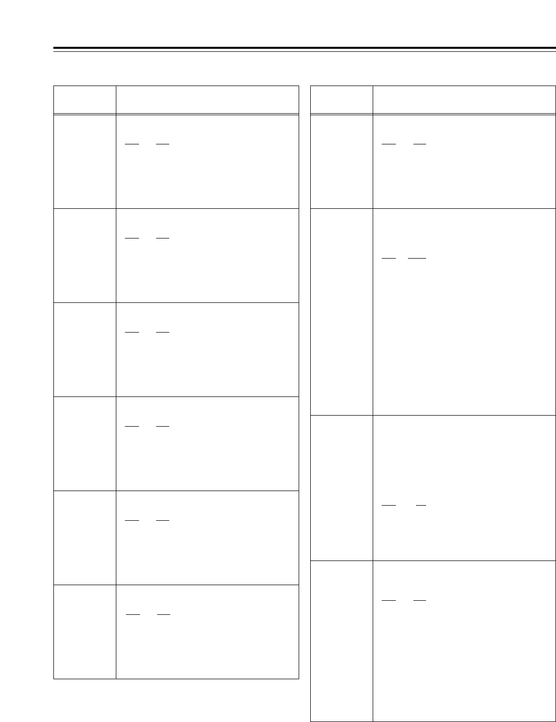
101
Setup menus
The underlining (__) denotes the factory setting mode.
<AUDIO> (continued)
No./Item Description of setting No./Item Description of setting
739
CH2 CUE SEL
For selecting the CH2 output status of the
main signal line in the search mode.
0000 OFF
:
The CUE signal is not output.
0001 ON
:
The CUE signal is output.
<Note>
For details on the audio output statuses, refer to “Audio
outputs in the search mode” on page 103.
740
CH3 CUE SEL
For selecting the CH3 output status of the
main signal line in the search mode.
0000 OFF
:
The CUE signal is not output.
0001 ON
:
The CUE signal is output.
<Note>
For details on the audio output statuses, refer to “Audio
outputs in the search mode” on page 103.
745
CH8 CUE SEL
For selecting the CH8 output status of the
main signal line in the search mode.
0000 OFF
:
The CUE signal is not output.
0001 ON
:
The CUE signal is output.
<Note>
For details on the audio output statuses, refer to “Audio
outputs in the search mode” on page 103.
741
CH4 CUE SEL
For selecting the CH4 output status of the
main signal line in the search mode.
0000 OFF
:
The CUE signal is not output.
0001 ON
:
The CUE signal is output.
<Note>
For details on the audio output statuses, refer to “Audio
outputs in the search mode” on page 103.
742
CH5 CUE SEL
For selecting the CH5 output status of the
main signal line in the search mode.
0000 OFF
:
The CUE signal is not output.
0001 ON
:
The CUE signal is output.
<Note>
For details on the audio output statuses, refer to “Audio
outputs in the search mode” on page 103.
743
CH6 CUE SEL
For selecting the CH6 output status of the
main signal line in the search mode.
0000 OFF
:
The CUE signal is not output.
0001 ON
:
The CUE signal is output.
<Note>
For details on the audio output statuses, refer to “Audio
outputs in the search mode” on page 103.
746
MONI CH SEL
For selecting the monitor output.
0000 MANU
:
The signal selected by the MONITOR SELECT
button is output.
0001 AUTO
:
The PCM audio signal is output in the j1.0k
to i2.0kspeed range; the CUE signal is
automatically output at all other speeds.
0002 PCM
:
The PCM audio signal is output in the j32kto
i32kspeed range.
<Notes>
• When “AUTO” is selected and a tape in any format
except DVCPRO HD-LP is played back, the PCM
audio signals are output in the -1.0kto +1.1kspeed
range.
• This setting takes effect when the L and R MONITOR
SELECT switches on the VTR’s front panel have
selected a channel from CH1 to CH8.
(If they have selected CUE, the CUE signal is output
at all speeds regardless of this menu item’s setting.)
747
MON AUTO
SEL
For selecting the channel for the monitor
output to be switched to CUE.
When a setting other than “MANU” has been
selected for setup menu item No.746 (MONI CH
SEL), the CUE signal is automatically output to
the monitor output in accordance with the
operation mode, and the monitor channel to be
switched to CUE is selected automatically.
0000 L/R
:The CUE signal is output both
to the Lch and Rch.
0001 L
:The CUE signal is output to the
Lch only.
0002 R
:The CUE signal is output to the
Rch only.
744
CH7 CUE SEL
For selecting the CH7 output status of the
main signal line in the search mode.
0000 OFF
:
The CUE signal is not output.
0001 ON
:
The CUE signal is output.
<Note>
For details on the audio output statuses, refer to “Audio
outputs in the search mode” on page 103.
748
MONI SEL INH
For selecting whether to enable or inhibit the
operation of the MONITOR SELECT button on
the front panel.
0000 OFF
:The button’s operation is
enabled.
0001 ON
:The button’s operation is
inhibited.
0002 ON1
:In the FULL display mode,
operation is prohibited; in the
FINE display mode only,
operation is enabled.
<Note>
Whether to enable or inhibit the button’s operation can
be selected for channels whose signals have not been
mixed by the setup menu item No.737 (MONI MIX)
setting.
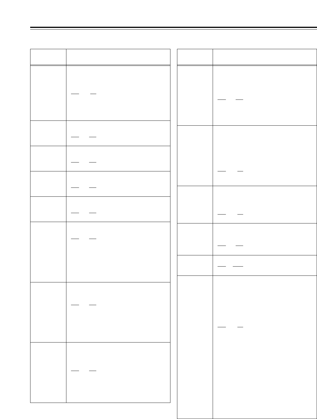
102
749*1
AUDIO PB VR
For selecting whether the playback level
adjustment controls are to function in the EE
mode when INT SG has been selected on the
<AUDIO> function menu.
0000 DIS
:The INT SG output level is fixed
at the UNITY level.
0001 ENA
:The INT SG output level can be
varied using the playback level
adjustment controls.
Setup menus
The underlining (__) denotes the factory setting mode.
<AUDIO> (continued)
No./Item Description of setting No./Item Description of setting
750
ANA CH1 SEL
For selecting the signal to be output to analog
output CH1.
0000 CH1
:The CH1 signal is output.
0001 CH5
:The CH5 signal is output
751
ANA CH2 SEL
For selecting the signal to be output to analog
output CH2.
0000 CH2
:The CH2 signal is output.
0001 CH6
:The CH6 signal is output.
752
ANA CH3 SEL
For selecting the signal to be output to analog
output CH3.
0000 CH3
:The CH3 signal is output.
0001 CH7
:The CH7 signal is output.
753
ANA CH4 SEL
For selecting the signal to be output to analog
output CH4.
0000 CH4
:The CH4 signal is output.
0001 CH8
:The CH8 signal is output.
754
SD SDI CH1
SL
For selecting the audio CH1 signal to be
superimposed onto the SD SDI output.
0000 CH1
:The CH1 signal is output.
0001 CH2
:The CH2 signal is output.
0002 CH3
:The CH3 signal is output.
0003 CH4
:The CH4 signal is output.
0004 CH5
:The CH5 signal is output.
0005 CH6
:The CH6 signal is output.
0006 CH7
:The CH7 signal is output.
0007 CH8
:The CH8 signal is output.
757
SD SDI CH4
SL
For selecting the audio CH4 signal to be
superimposed onto the SD SDI output
0000 CH1
:The CH1 signal is output.
0001 CH2
:The CH2 signal is output.
0002 CH3
:The CH3 signal is output.
0003 CH4
:The CH4 signal is output.
0004 CH5
:The CH5 signal is output.
0005 CH6
:The CH6 signal is output.
0006 CH7
:The CH7 signal is output.
0007 CH8
:The CH8 signal is output.
758
JOG PROC
For selecting how to process the digital audio
output slow signals in the JOG, VAR or SHTL
mode.
0000 OFF
:
The sound without having the digital audio
output slow signals processed is output even
when the STILL mode is established.
0001 ON
:
The sound after having the digital audio output
slow signals processed is output.
759
DV PB ATT
For selecting the audio output level during DV
format playback.
0000 OFF
:
The audio output level is not attenuated.
0001 ON
:
The audio output level is attenuated.
760*1
REC PT MUTE
For selecting whether to mute the sound at
the joins between recordings during DV or
DVCAM format playback.
0000 OFF
:The sound is not muted.
0001 ON
:The sound is muted.
761*1
AUDIO INT SG
For selecting the type of internal signal.
0000 TONE
:A sine wave signal is selected.
0001 SILNCE
:A silent signal is selected.
755
SD SDI CH2
SL
For selecting the audio CH2 signal to be
superimposed onto the SD SDI output
0000 CH1
:The CH1 signal is output.
0001 CH2
:The CH2 signal is output.
0002 CH3
:The CH3 signal is output.
0003 CH4
:The CH4 signal is output.
0004 CH5
:The CH5 signal is output.
0005 CH6
:The CH6 signal is output.
0006 CH7
:The CH7 signal is output.
0007 CH8
:The CH8 signal is output.
*1: This item is not displayed when the 23/24 Hz or 25 Hz (HD or
SD) mode has been selected as the system menu item No.25
(SYSTEM FREQ) setting.
756
SD SDI CH3
SL
For selecting the audio CH3 signal to be
superimposed onto the SD SDI output
0000 CH1
:The CH1 signal is output.
0001 CH2
:The CH2 signal is output.
0002 CH3
:The CH3 signal is output.
0003 CH4
:The CH4 signal is output.
0004 CH5
:The CH5 signal is output.
0005 CH6
:The CH6 signal is output.
0006 CH7
:The CH7 signal is output.
0007 CH8
:The CH8 signal is output.
762
AUD RATE
CON
This item enables signals to be recorded and
played back without passing them through
the rate converter in the audio input/output
section (without engaging the digital filter).
0000 OFF
:
The signals are recorded and played back
without passing them through the rate
converter.
0001 ON
:
The signals are recorded and played back after
passing them through the rate converter.
<Notes>
•ON/OFF control is exercised at the same time for
both recording and playback. It cannot be set
differently for recording or playback.
•ON/OFF control is exercised at the same time for
CH1 to CH8. ON or OFF cannot be set
independently for each channel.
•When the rate converter is set to OFF, the video input
signals and AES (EBU) input signals must be
synchronized. Moreover, the video input signals and
reference signal selected by OUT REF must also be
synchronized. (Noise may occur if these signals are
not synchronized.)
•In the 60 Hz mode, noise may occur if OFF is set for
the rate converter.
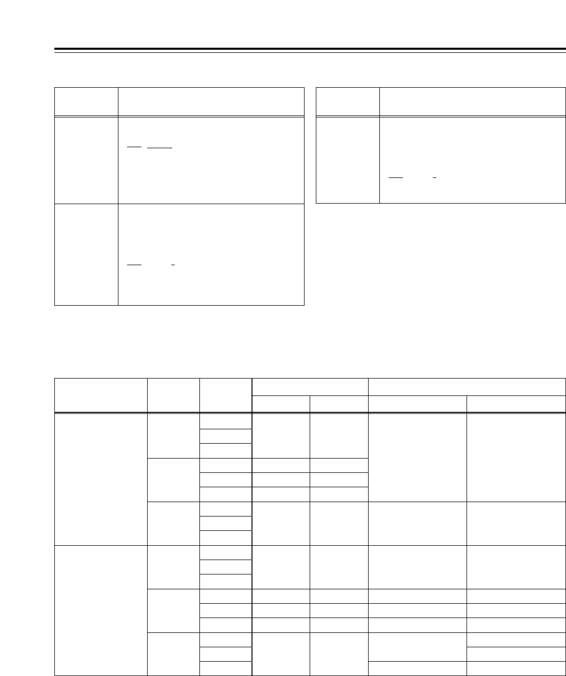
103
Setup menus
<AUDIO> (continued)
No./Item Description of setting No./Item Description of setting
763
METER
SCALE
(This menu is
not displayed for
AJ-HD1700E.)
For selecting the scale display of the audio
level meter.
0000 PEAK_0
:
[The audio level is displayed with 0 dB as the
maximum level.
0001 REF_0
:
The audio level is displayed with 0 dB as the
reference level.
Audio outputs in the search mode
The table below lists the signals which are output to the monitor and main signal line and which are determined by how the settings of menu
items No.738 to No.745, and No.746 and No.747 are combined.
791
CUE PB VOL
For adjusting the playback level of the CUE
audio signal.
(j¶ to 0 dB to i12 dB)
0032 16
::
0016 0
::
0000
j
16
*3: During fast forwarding or rewinding, the CUE signal is output
automatically.
*4: During fast forwarding or rewinding, this signal is muted.
*5: This item is not displayed when the 23/24 Hz mode or 25 Hz (HD
or SD) mode has been selected as the system menu item No.25
(SYSTEM FREQ) setting.
L/R
L
R
CUE*2
CUE*2
PCM*1
CUE*2
PCM*1
CUE*2
CUE*2CUE*2
CUE*2PCM*1
PCM*1
PCM*4
CUE*2
PCM*3
PCM*4
PCM*3
AUTO
738 CH1 CUE SEL:
:
745 CH8 CUE SEL
OFF
MANU
AUTO
PCM
MANU
L/R
L
R
L/R
L
R
L/R
L
R
L/R
L
R
L/R
L
R
PC*1PCM*1
CUE*2
CUE*2
PCM*1
PCM*3PCM*3
PCM*3PCM*3
PCM*1
CUE*2
PCM*1
CUE*2
PCM*1
PCM*1PCM*1
PCM*4PCM*4
PCM*1PCM*1
PCM*3
PCM
ON
746
MONI CH
SEL
747
MON AUTO
SEL
Monitor output Main signal line output
CH1/CH3/CH5/CH7Lch Rch CH2/CH4/CH6/CH8
<Notes>
*1: The PCM audio output is muted if the tape is played back at a
speed in the j1.0kto i2.0krange (or at a speed in the j1.0k
to i1.1krange for a format other than DVCPRO HD-LP).
*2: In the case of the CUE audio output, the PCM signals are output
if the tape is played back at a speed in thejj1.0kto i2.0k
range (or at a speed in the -1.0kto +1.1krange for a format
other than DVCPRO HD-LP).
The underlining (__) denotes the factory setting mode.
790*5
CUE REC VOL
For adjusting the recording level of the CUE
audio signal.
(j¶ to 0 dB to i12 dB)
0032 16
::
0016 0
::
0000
j
16
<Note>
This item is not displayed
when the 23/24 Hz mode has
been selected as the system
menu item No.25 (SYSTEM
FREQ) setting.
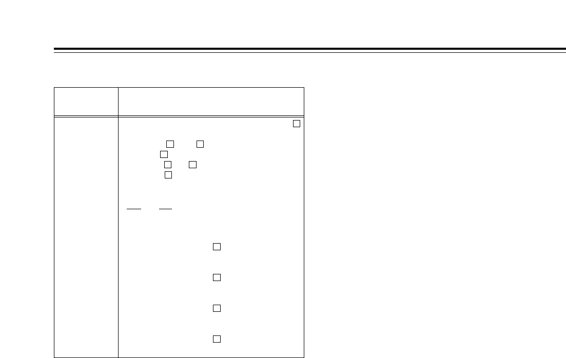
104
Setup menus
The underlining (__) denotes the factory setting mode.
<MENU>
No./Item Description of setting
A02
P. ON LOAD
This VTR is equipped with VTR MEMORY
for storing the current settings (*1) and VTR
MEMORY to for backing up VTR
MEMORY . The data of a selected VTR
MEMORY to can be loaded into VTR
MEMORY and operation started on the
basis of this data when the power is turned
on.
0000 OFF
:
Operation is started using the previous
settings.
0001 USER1
:
The VTR MEMORY data is loaded and
operation started on the basis of this data.
0002 USER2
:
The VTR MEMORY data is loaded and
operation started on the basis of this data.
0003 USER3
:
The VTR MEMORY data is loaded and
operation started on the basis of this data.
0004 USER4
:
The VTR MEMORY data is loaded and
operation started on the basis of this data.
4
3
2
1
C
41
C
41
C
*1: The term “settings” here denotes all the settings of the setup
menus, what is registered in the PF1/PF2 menus, and the
contents of some of the function buttons.
<Connections with Dolby-E* components>
When the VTR is to be connected to a Dolby-E encoder/decoder for recording or playing back Dolby-E data, set
the audio input and output levels to UNITY, and select the following setup menu item settings.
<Notes>
• Dolby-E data cannot be recorded or played back in
the 60 Hz mode.
• Adjust the timing with the video signals to cover the
time taken by the Dolby-E component for
encoding/decoding outside the VTR.
• Set the bit depth of the Dolby-E encoder/decoder to
16 bits.
• Noise will be output from the ANALOG AUDIO OUT
connectors of the channels through which the
Dolby-E data is passing.
• The audio level meter will deflect beyond the range
of its markings for those channels through which
the Dolby-E data is passing.
• Noise will be output when a tape on which Dolby-E
data has been recorded is played back in the JOG
or VAR mode.
* Dolby and the Double D symbol Îare trademarks of
Dolby Laboratories Licensing Corporation.
No.303 AUD EDIT IN = CUT
No.304 AUD EDIT OUT = CUT
No.725 REC CH1 = CH1
No.726 REC CH2 = CH2
No.727 REC CH3 = CH3
No.728 REC CH4 = CH4
No.729 REC CH5 = CH5
No.730 REC CH6 = CH6
No.731 REC CH7 = CH7
No.732 REC CH8 = CH8
No.734 PB FADE = CUT
No.758 JOG PROC = OFF
No.762 AUD RATE CON = OFF
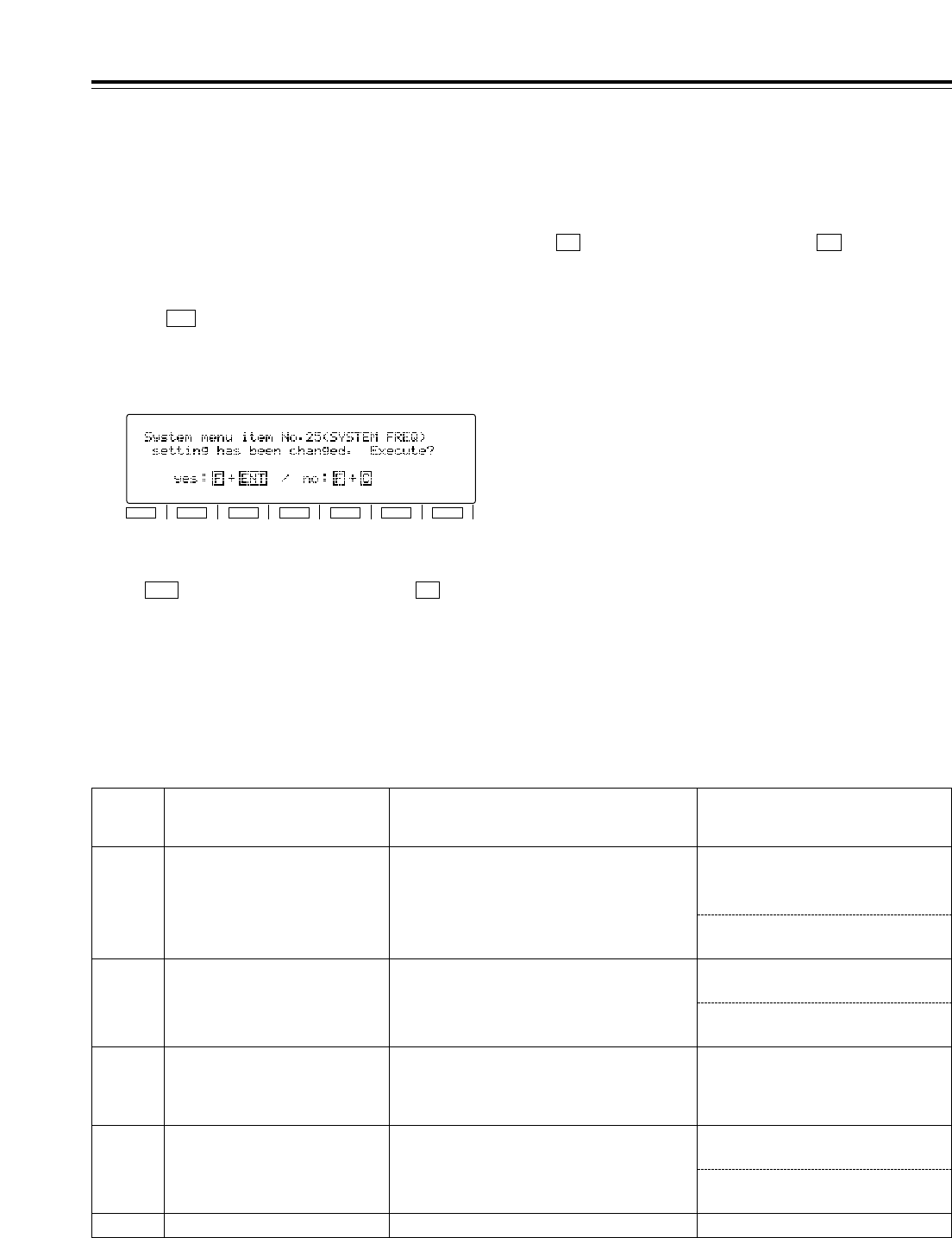
105
Setup menus
Follow the steps below to switch the system frequency (59/60 Hz, 50 Hz, 23/24 Hz, 25 Hz (HD) or 25 Hz(SD)).
<How to switch the system frequency>
1Following the procedure for the <SETUP
MENU/SYSTEM MENU> (page 60) to change the
system menu item No.25 (SYSTEM FREQ) setting.
2Press (SET) to enter the setting, and after the
function menu shown on the time code display area
>
has been cleared, the following message
appears.
F5
3To make the setting entered in step 2 valid, press
the button while holding down the button.
The system is restarted, and the VTR starts
operating in the selected mode.
FENT
4To cancel the setting entered in step 2, press the
button while holding down the button.
The above message is cleared, and after the
changed setting has been restored to the original
system menu No.25 (SYSTEM FREQ) setting,
operation returns to the SYSTEM menu operation
screen.
FC
<Note>
If the system menu No.25 (SYSTEM FREQ) setting
has been changed while a cassette is inserted in the
VTR, the cassette is automatically ejected.
The same procedure as above is also followed when
the system menu No.25 (SYSTEM FREQ) setting has
been changed by loading the data from an IC card in
accordance with the <CARD> procedure (page 69).
Note that even if the change being made to the system
menu item No. 25 setting is cancelled, other system
menu items affected by the change will be updated, as
will the associated file names.
F1
SHIFT
F2 F3 F4 F5 F6
No.25
SYSTEM
FREQ Format enabling recording Format enabling playback Sync signals
50/60
1080/59.94i (HD_LP)
1080/60.00i (HD_LP)
720/59.94p (HD_LP)
720/60.00p (HD_LP)
1080/59.94i (HD_LP, HD_SP)
1080/60i (HD_LP, HD_SP)
720/59.94p (HD_LP, HD_SP)
720/60.00p (HD_LP, HD_SP)
480/59.94p (480p)
480/59.94i (422, 411, DV, DVCAM)
The setting selected for setup menu
item No.031 (OUT REF) applies.
HD_REF (59.94Hz, 60Hz)
SD_REF (59.94Hz)
50 1080/50i (HD_LP)
1080/50i (HD_LP, HD_SP)
576/50i (422, 411, DV, DVCAM)
576/25p over 50i (422, 411, DV)
HD_REF (50Hz)
SD_REF (50Hz)
23/24 None
720/23.98p over 59.94p (HD_SP/HD_SP)
720/24p over 60.00p (HD_SP/HD_SP)
480/23.98p over 59.94i [2:3 mode]
480/23.98p over 59.94i [2:3:3:2 advance mode]
HD_REF (47.96Hz, 48Hz)
The setting selected for setup menu
item No.031 (OUT REF) applies.
25 (HD) None 720/25p over 60p
HD_REF (50Hz)
SD_REF (50Hz)
25 (SD) None 720/25p over 60p SD_REF (50Hz)
The setting selected for setup menu
item No.031 (OUT REF) applies.
<Selecting the recording/playback format and sync signals which support the
operation mode>
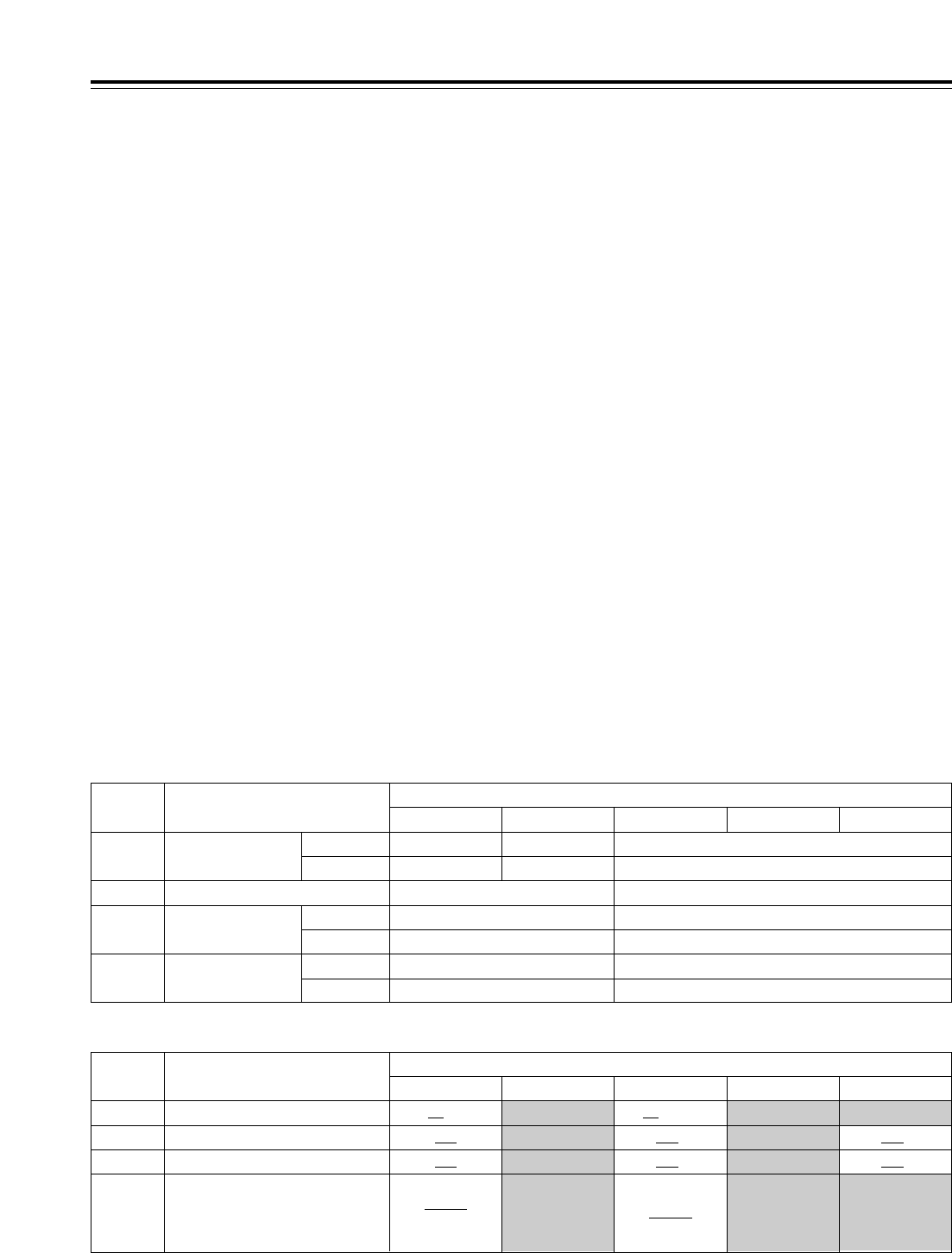
2F
106
2F 2F
Setup menus
<Menu management accompanying switching the system frequency>
The system menu and setup menu have some items whose settings differ and other items with which no
selection options are displayed and whose settings are fixed (indicated by the shading in the table below),
depending on the switching of the operation mode in response to the setting selected for system menu item
No.25 (SYSTEM FREQ). (Refer to the table below.)
<50P IN/OUT> 50-pin connector registration
• When the items whose settings differ have been
registered in the <50P IN/OUT> 50-pin connector
pins, the settings corresponding to the operation
modes are allocated to the IN and OUT pins on the
basis of the setting numbers. However, when the
upper limit value is exceeded, the value will be
limited to this upper limit.
What has been registered is saved, but bear in mind
that when the data is registered again, it is saved by
overwriting the existing data so that the previously
registered data will be lost.
• If items, whose selection options are not displayed
due to the operation mode, have been registered in
the <50P IN/OUT> 50-pin connector, when an
operation mode in which these options are not
displayed is selected, what has been registered is
saved but no operation is possible. Bear in mind,
however, that when the data is registered again, it is
saved by overwriting the existing data so that the
previously registered data will be lost.
System menu and setup menu settings
• Each of the items whose settings differ is saved in
the VTR MEMORY (current file and one of the
backup files 1 to 4). The settings that correspond to
each operation mode will be displayed so that the
settings can be performed for each operation mode.
Registration of the <PF1> and <PF2> function
buttons
• When the items whose settings differ have been
registered in the <PF1> and <PF2> function buttons,
the settings that correspond to each operation mode
will be displayed so that the settings can be performed
for each operation mode.
• If items, whose selection options are not displayed due
to the operation mode, have been registered in the
<PF1> or <PF2> function button, when an operation
mode in which these options are not displayed is
selected, what has been registered is saved but the
function button itself will become blank and cannot be
operated. Bear in mind, however, that when the data is
registered again, it is saved by overwriting the existing
data so that the previously registered data will be lost
.
No. Menu item System menu No.25 (SYSTEM FREQ)
59/60 23/24 50 25 (HD)
14
12 SYS H (HD) COARSE
j5H to 0H to 5H
j5H to 0H to 5H
FINE
j1100 to 0 to 1100
j5H to 0H to 5H
j1375 to 0 to 1375
j1320 to 0 to 1320
15 VO SYS H (SD) COARSE j5H to 0H to 5H j5H to 0H to 5H
FINE j858 to 0 to 858 j864 to 0 to 864
16 SD SYS D (SD) COARSE j5H to 0H to 5H j5H to 0H to 5H
FINE j858 to 0 to 858 j864 to 0 to 864
SYS SC (SD) j108 to 0 to 108 j115 to 0 to 115
System menu
No. Menu item System menu No.25 (SYSTEM FREQ)
59/60 23/24 50 25 (HD)
502
2F/4F 2F/4F/8F109 CAP.LOCK
501 VITC POS-1
VITC POS-2
600 VIDEO IN SEL
10L to 16L to 20L
INTSG
HDSDI
SDTI
SDSDI
7L to 11L to 22L
INTSG
HDSDI
SDSDI
25 (SD)
7L to 11L to 22L
10L to 18L to 20L
7L to 13L to 22L 7L to 13L to 22L
Setup menus
(Continued on next page)
25 (SD)
The underlining (__) denotes the factory setting mode.
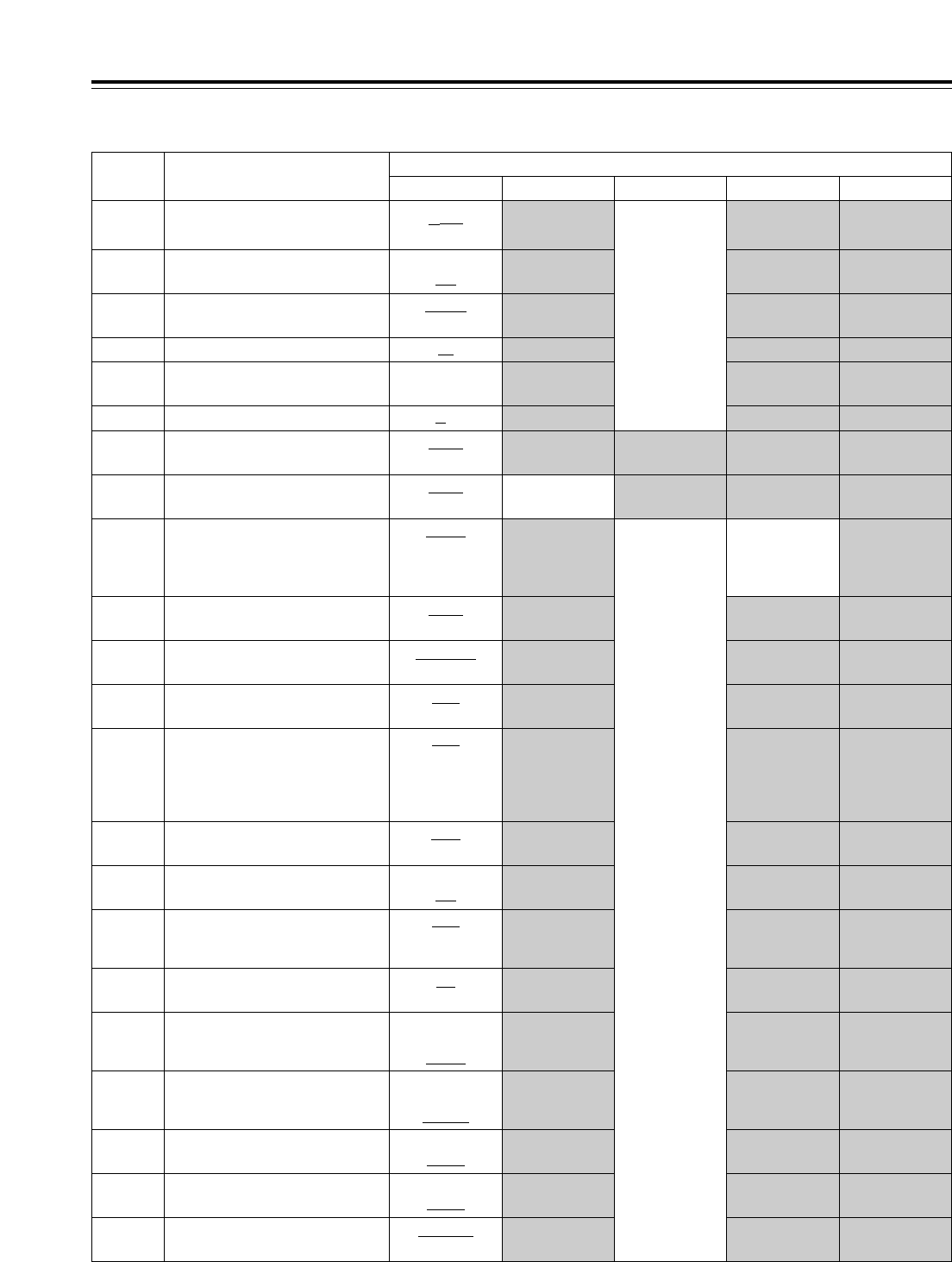
60/24
107
Setup menus
No. Menu item System menu No.25 (SYSTEM FREQ)
59/60 23/24 50 25 (HD)
d12h
24h
Same as for
59/60
002 TAPE TIMER
OFF
ON
004 SYNCHRONIZE
MANU
AUTO
010 MONI CONTROL
0s to 3s to 5s012 REC ADJUST
OFF
ON
013 DET STOP
AUTO
INPUT
HD_REF
SD_REF
HD_REF
Same as for
59/60
Same as for
59/60
031 OUT REF
S/F/R
STOP
105 AUTO EE SEL
NORMAL
THRU
107 EE MODE SEL
OFF
ON
111 MEMORY STOP
OFF
ALL
PRE
NORMAL
V/CTL
ALL ALL113 REC INH
REC
OFF
115 EJECT SW INH
OFF
ON
118 SP MODE INH
OFF
LOW
HIGH
135 DET BEEP
EE
TAPE TAPE TAPE140 OUTPUT
REC
PB
AUTO
141 VOLUME
IN
OUT
IN/OUT
142 AUDIO UNITY
PB PB
OUT OUT
CUT
FADE
303 AUD EDIT IN
CUT
FADE
304 AUD EDIT OUT
PLAYER
RECORDER
306 CF ADJ SEL
ALL
TAPE
PB
OUT
j8f to 0f to 3s10f
014 DET ADJUST
Setup menus
59/23
60/24 Same as for
59/60 60/24030 HD FREQUENCY
1080i
720p 720p 1080i 720p
25 (SD)
SD_REF
720p020 SYS FORMAT
The underlining (__) denotes the factory setting mode.
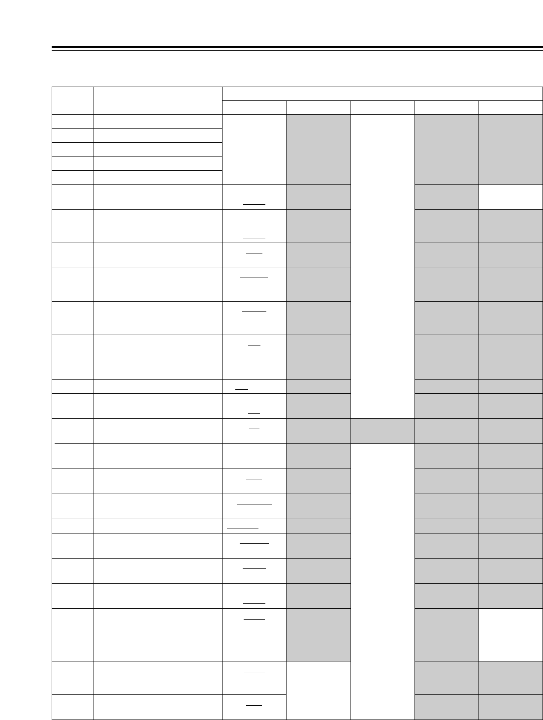
OFFOFF
Same as for
59/60
PRE PRE
50
Same as for
59/60
108
BLANK
THRU BLANK BLANK500 VITC BLANK
Setup menus
Setup menus
No. Menu item System menu No.25 (SYSTEM FREQ)
59/60 23/24 25 (HD) 25 (SD)
N-DEF
CH1
CH2
CH1+3
320 EDIT RPLCE1
321 EDIT RPLCE2
322 EDIT RPLCE3
323 EDIT RPLCE4
Same as for
59/60
324 EDIT RPLCEC
REGEN
PRE
AUTO PRE503 TCG MODE
TC&UB
TC
UB
505 TCG REGEN
AS&IN
ASSEM
INSRT
506 REGEN MODE
INT
EXT_L
SLTC
SVITC
507 TC SOURCE
REC
FREE
504 RUN MODE
NDF
V OUT
TC IN
512 TC OUT REF
DF
NDF NDF NDF511 DF MODE
000 to 111508 BINARY GP
OFF
ON
510 TCG CF FLAG
OFF
EDIT
516 TC OUT ADV
MOMENT
LATCH
517 TCG OUT
100%CB to EQ601 VIDEO INT SG
DR OFF
DR ON
602 SDI IN MODE
FIELD
FRAME
604 FREEZE SEL
OFF
AUTO
605 INTERPOLATE OFF
FIT_V
FIT_H
FIT_HV
14:9
13:9
620 DOWNCON MODE Same as for
59/60
FIT_V
FIT_H
FIT_HV
621 UPCON MODE
STD
NARROW
624 U/C RESP H
Same as for
59/60
The underlining (__) denotes the factory setting mode.
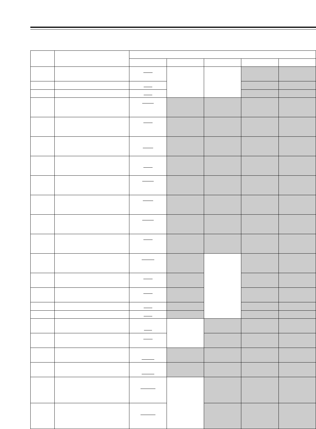
109
Setup menus
Setup menus
No. Menu item System menu No.25 (SYSTEM FREQ)
59/60 23/24 50 25 (HD) 25 (SD)
The underlining (__) denotes the factory setting mode.
BLANK
1080i
720p
- - -
634 480p #HD OUT
480p
480p
480i
635 480p #SD OUT
1080i
720p
- - -
636 480i #HD OUT
480i
480i
480p
637 480i #SD OUT
FIT_V
FIT_H
FIT_HV
Same as for
59/60
638 IN U/C MODE
STD
NARROW
639 I U/C RESP H
STD
NARROW
640 I U/C RESP V
Pb-Pr
U-V Same as for
59/60
651 HUE STYLE
OFF
ON
676 BLK CLIP
BLANK
THRU BLANK BLANK680 CC (F1) BLANK
BLANK
THRU BLANK681 CC (F2) BLANK
THRU
ADD22
ADD21
ADD20 Same as for
59/60
682
(525 system
only)
VO SETUP (HD)
THRU
ADD22
ADD21
ADD20
683
(525 system
only)
VO SETUP (SD)
0 dB to +1 dB to 2 dB
641 I U/C ENH H
0 dB to +1 dB to 2 dB
BLANK
BLANK
642 I U/C ENH V
1080i
720p
1080i
630 1080i #HD OUT
480i
- - -
480p
631 1080i #SD OUT
1080i
720p
720p
632 720p #HD OUT
- - -
480i
480p
633 720p #SD OUT
STD
NARROW Same as for
59/60 Same as for
59/60
625 U/C RESP V
0 dB to +1 dB to 2 dB
628 U/C ENH H
0 dB to +1 dB to 2 dB
629 U/C ENH V
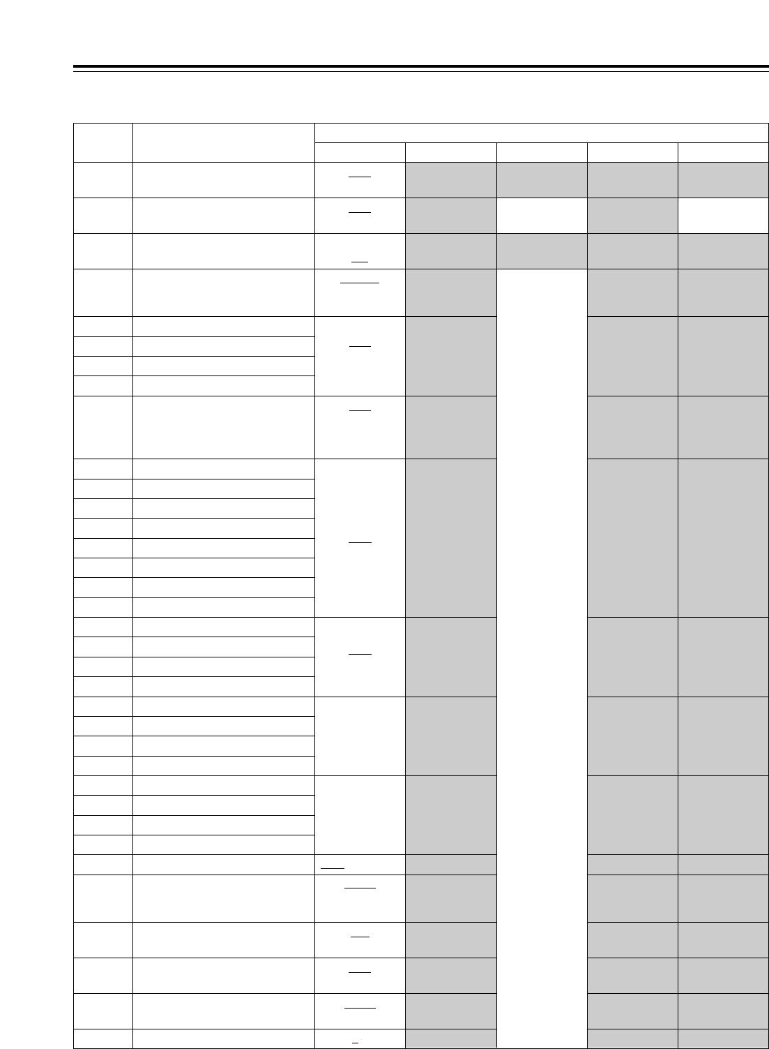
Same as for
59/60
25 (SD)
110
Setup menus
No. Menu item System menu No.25 (SYSTEM FREQ)
59/60 23/24 50 25 (HD)
Setup menus
The underlining (__) denotes the factory setting mode.
719 CH7 IN SEL
720 CH8 IN SEL
AES
SDI
721 D IN SEL 12
722 D IN SEL 34
723 D IN SEL 56
724 D IN SEL 78
CH1 to CH3i4
725 REC CH1
726 REC CH2
727 REC CH3
728 REC CH4
CH5 to CH7i8
729 REC CH5
730 REC CH6
731 REC CH7
732 REC CH8
CUE to CH1j8733 REC CUE
AUTO
CUT
FADE CUT CUT734 PB FADE
DIS
ENA
749 AUDIO PB VR
OFF
ON
760 REC PT MUTE
TONE
SILNCE SILNCE SILNCE761 AUDIO INT SG
16 to 0 to j16790 CUE REC VOL
INT SG
DIGI
ANA
713 CH1 IN SEL
714 CH2 IN SEL
715 CH3 IN SEL
716 CH4 IN SEL
717 CH5 IN SEL
718 CH6 IN SEL
OFF
ON
688 CC REC
Same as for
59/60
BLANK
THRU
MANU
695 BLANK LINE
4dB
0dB
j20dB
700 CH1 IN LV
701 CH2 IN LV
702 CH3 IN LV
703 CH4 IN LV
4dB
0dB
j20dB
j60dB
704 CUE IN LV
Same as for
59/60
OFF
ON
686 CCR MODE
OFF
ON
687 SDI INDEX O

111
Time code and user’s bit
Time code
The time code is used when the time code signal
generated by the time code generator (time code
signal generator) is to be recorded on the tape, its
values are to be read by the time code reader (time
code signal reader), and the absolute position of the
tape is to be displayed in increments of hours,
minutes, seconds and frames.
The time code is written in the sub-code area (data
area) of the helical track. This enables insert editing
to be conducted independently using the time code
alone. In addition, the VTR’s playback speed can be
read from the stop mode to the slow motion playback
up to high-speed playback (approx. 50knormal
speed or approx. 100knormal speed when using a
DVCPRO tape).
The time code values are indicated on the display and
superimposed display.
TCR 00 : 07 : 04 : 23
tttt
Hours Minutes Seconds Frames
User’s bit
The “user’s bit” refers to the 32-bit (8-digit) data frame
among the time code signals which has been released
to users. It enables operator numbers and other
values to be recorded.
The alphanumerics which can be used for the user’s
bit are number 0 to 9 and letters A to F.
Setting the internal time code
1Set the VTR to the stop mode.
4Setting RUN MD on the <TC> menu
REC:
The time code advances simultaneously with the
recording.
FREE:
The time code advances, like time, irrespective of
the VTR operation.
F5
5Setting TCG MD on the <TC> menu
REGEN:
The continuity of the underlying time code in place
prior to editing is maintained.
PRE:
The time code can be preset using the operation
panel controls or remote controller.
AUTO:
The time code is automatically switched to REGEN
or PRE depending on the VTR
’
s operation mode:
during editing, REGEN is selected; at all other
times, PRE is selected.
F3
6Registering the TC preset values
Display the <HOME> menu.
<TC/UB>
•Preset (in the preset enable status)
1When among the number keys is pressed,
the TC display switches to TCG (UBG), and
the TCG value characters (all digits) are
highlighted.
2When is pressed again, one digit is
highlighted, and the change enable status is
established.
3Input the desired value using the number
keys. The entire input value can be cleared
by pressing while holding down .
4To input the letters used with the user
’
s bit,
press the same number key (toggle by
tapping or ) while holding down . To
move from one digit to another, turn the ADJ
dial.
5To enter the value, press the key.
6When the display screen has been changed
during the input process or if the button
has been pressed, the change enable status
is released, and the setting is canceled.
<CTL>
•Reset
Press (TC CLR).
F4
C
ENT
F87
F0
T
T
2Set TC/CTL on the <HOME> menu to TC.
F3
3Set SOURCE on the <TC> menu to INT (for
selecting the internal time code).
F1
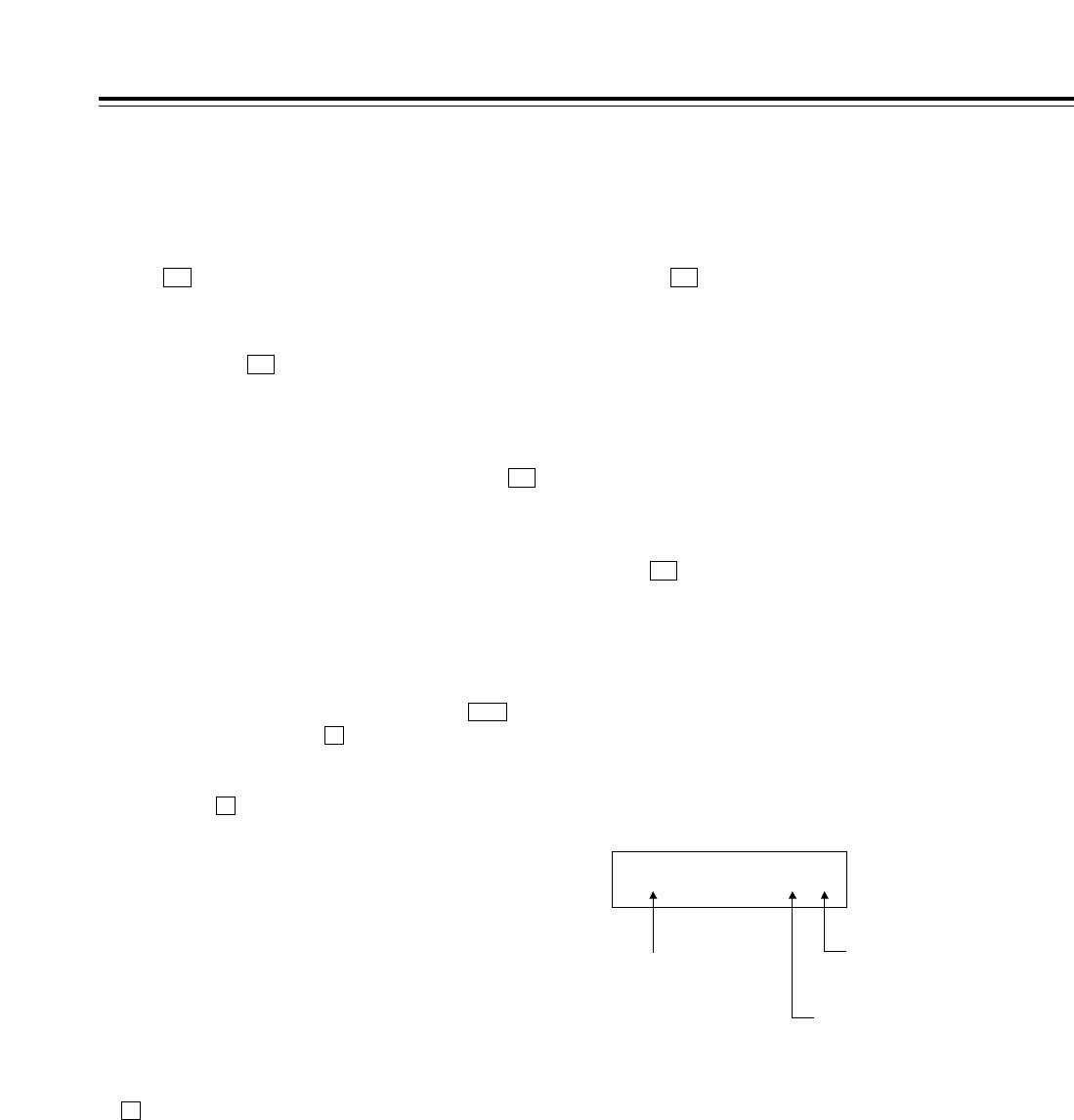
112
Concerning the time code and user’s bit
Setting the external time code
1Set the VTR to the stop mode.
3If the video input has been set to HD SDI input or
INT SG, set TC SRC on the <TC> menu to
EXT-L, SLTC or SVITC.
F1
4If the video input has been set to SD SDI (when
the optional board has been installed), set TC
SRC on the <TC> menu to EXT-L or VITC.
F1
2Set TC/CTL on the <HOME> menu to TC.
F3
Cue time registration, preroll and
cue-up
(These functions work only on the HOME, PF1 and
PF2 screens.)
• Registration
Register the cue time by pressing the button
while holding down the button.
• Presetting
When the button is pressed, the characters of
the cue time or TC/UB display are highlighted.
Turn the ADJ dial to highlight the characters of the
cue time.
The subsequent steps in the registration procedure
are the same as for TCG.
• Prerolling
Press the PREROLL button to preroll the tape to
the currently registered CUE point.
• Cue-up
Press the PREROLL button while holding down the
button to cue the tape up to the currently
registered CUE point.
F
T
F
SET
Time code and user’s bit playback
1Set the VTR to the stop mode.
3Press the PLAY button. Playback starts, and the
time code appears on the display.
If (SUPER) on the <TC SHIFT> menu is set to
ON, the time code value is superimposed onto the
video signals from the VIDEO OUT3 connector.
F1
<Notes>
• While a drop frame time code is being read, the
colon between the seconds and frames is replaced
with a period.
• If the time code signal is missing, it is interpolated
automatically using the CTL signal.
The following appears on the display.
2Set TC/CTL on the <HOME> menu to TC or
UB.
TC:
The time code is displayed.
UB:
The user’s bit is displayed.
• In the event that it has become impossible to
read the time code, it is interpolated using the
CTL signal.
F3
T ¢ R 00:01:04:07¢
An asterisk (¢)
appears here if the
time code signal is
missing.
“ ”: 1st, 3rd field
“¢”: 2nd, 4th fields
In the drop frame mode, the colon
between the seconds and frames
is replaced with a period. (In the
59/60 Hz mode only)

113
Display position
The position of the characters superimposed on the
display can be changed using (C HPOS) and
(C VPOS) on the <TC SHIFT> menu and the ADJ
dial.
F3F2
Superimpose screen
The control signals, time code, etc. are displayed on
this screen using abbreviations.
TCR 22 : 22 : 22 : 22
TV monitor
TCR 22 : 22 : 22 : 22
TV monitor
TCR 22 : 22 : 22 : 22
TV monitor
Abbreviations
CTL: Control signal count value
TCR: Time code data recorded in the SBC area
TCR.: Time code data recorded in the VAUX area
UBR: User’s bit data recorded in the SBC area
UBR.: User’s bit data recorded in the VAUX area
TCG: Time code data of the time code generator
UBG: User’s bit data of the time code generator
Operation mode
The VTR’s operation mode can also be displayed
using (DISPLY) on the <TC SHIFT> menu.
F4
TCR 22 : 22 : 22 : 22
STOP
TV monitor
VTR operation mode
Characters displayed
The background of the characters superimposed on
the display screen can be changed using (C
TYPE) on the <TC SHIFT> menu.
F5
TCR 22 : 22 : 22 : 22
TV monitor
TCR 22 : 22 : 22 : 22
TV monitor
<Note>
When the 23/24 Hz mode has been selected as the
system menu item No.25 (SYSTEM FREQ) setting,
the time code and other information superimposed on
the MONITOR and VIDEO OUT3 connectors are not
displayed.
<Note>
[T2R], [T2R.], [U2R] or [U2R.] is displayed when the
data has not been read correctly from the tape.
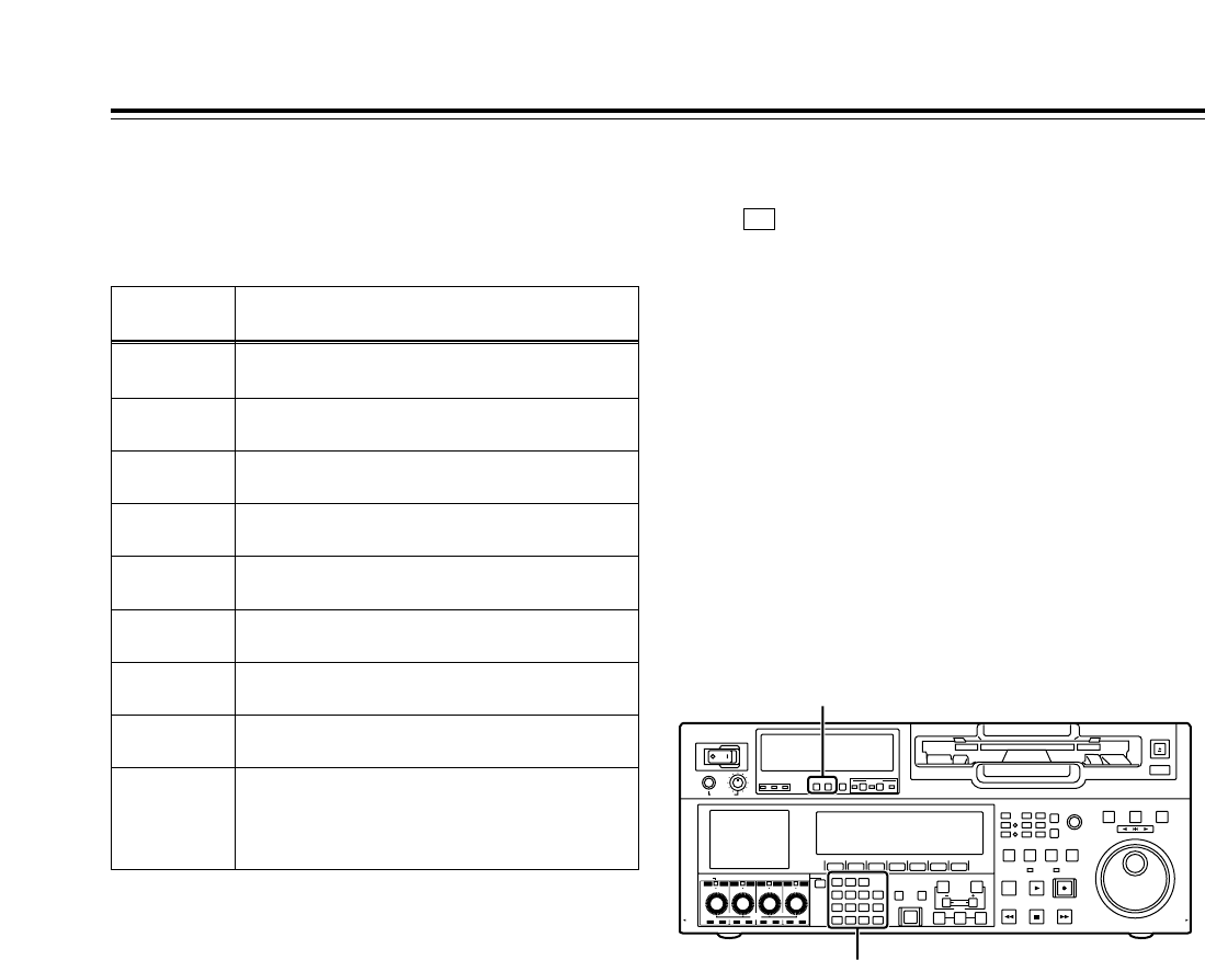
114
POWER
OFF
ON
HEADPHONES
PUSH
LOCK
FULL
CH CONDITION
MONITOR
FULL/FINE
REMOTE
LR
9P 50P
RS-232C
CH
12345678
CUE
XL/L/M
-
cassette
Do not insert S-cassette
without adapter
EJECT
AUDIO CH SELECT
SHIFT
ABC DEF GHI
JKL MNO PQRS
PREVIEW/
REVIEW
PRE-
ROLL
A IN A OUT
HOME RF1 ASSEM
ADJUST
SHTL
REV FWD
VARJOG
STAND BY
RECORDER INPUT CHECK
PLAYER
SERVO
EDIT PLAY REC
REW STOP FF
REC INHIBIT
PUSH-INTER
INSERT
RF2
VIDEO UNITY TC CUE
AUDIO UNITY DIAG MENU
TRIM
SET
IN
OUT
AUTO
EDIT
789
456BS
TUV WXYZ
123
ENT
0CT F
F1 F2 F3 F4 F5 F6
CH
1
CH
5
CH
2
CH
6
CH
3
CH
7
CH
4
CH
8
FULL
REC P8 REC P8 REC P8 REC P8
Selecting the audio recording channels and monitor output
Audio recording channels
The audio channels can be selected as shown below
using the AUDIO setup menu items.
Recording
track
CH1
Signals recorded
CH1 input, CH2 input, CH3 input, CH4 input,
CH1+CH2 input, CH3+CH4 input
CH2 CH1 input, CH2 input, CH3 input, CH4 input,
CH1+CH2 input, CH3+CH4 input
CH3 CH1 input, CH2 input, CH3 input, CH4 input,
CH1+CH2 input, CH3+CH4 input
CH4 CH1 input, CH2 input, CH3 input, CH4 input,
CH1+CH2 input, CH3+CH4 input
CH5 CH5 input, CH6 input, CH7 input, CH8 input,
CH5+CH6 input, CH7+CH8 input
CH6 CH5 input, CH6 input, CH7 input, CH8 input,
CH5+CH6 input, CH7+CH8 input
CH7 CH5 input, CH6 input, CH7 input, CH8 input,
CH5+CH6 input, CH7+CH8 input
CH8 CH5 input, CH6 input, CH7 input, CH8 input,
CH5+CH6 input, CH7+CH8 input
CUE
CUE input, CH1 input, CH2 input, CH3 input, CH4
input, CH5 input, CH6 input, CH7 input, CH8
input, CH1+CH2 input, CH3+CH4 input,
CH5+CH6 input, CH7+CH8 input, CH1–CH8 input
Monitor output channels
When (M MIX) on the <AUDIO SHIFT2> menu is
set to L, R or L/R, the signals of a multiple number of
channels can be mixed and output.
When the number key corresponding to the channel
whose signals are to be monitored is pressed while
the “L” (or “R”) button is held down, that channel is
selected, and its signals are displayed on the audio
level meter. (The same steps can also be taken to
de-select a channel which has already been selected.)
However, only up to 2 channels among the CH1-CH4
channels and only up to 2 channels among the CH5-
CH8 channels are selected.
(Examples: CH1 + CH3 + CH5 + CH8 can be selected
but CH1 + CH2 + CH4 cannot be selected.)
F6
Number keys
MONITOR SELECT switches

115
Display saving function
This function is provided to extend the service life of the
LCD monitor. It starts up if none of the front panel
controls have been operated or the cassette tape has not
been run at all for about 5 minutes.
While the saving function is working, the LCD monitor
display goes blank, and the “EX” symbol appears on the
time code display area.
To release the saving function, operate a button or dial
on the front panel or issue a tape transport command
from the controller. The operation performed to release
the function will be executed after the function is
released.
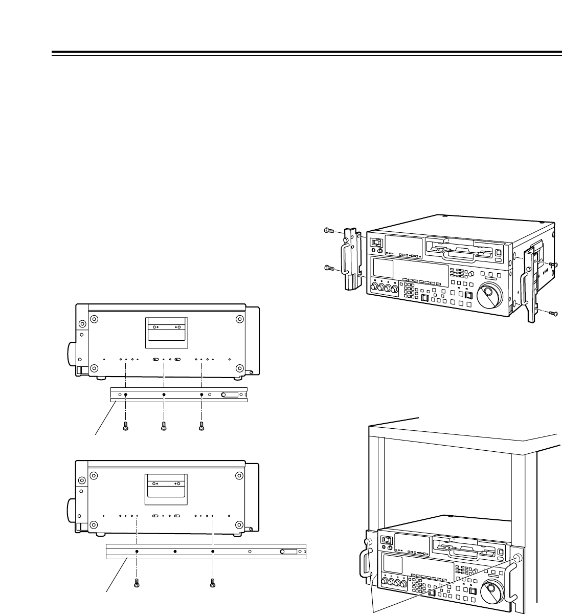
116
ABCDEF GH
2Attach the outer member brackets to the rack.
Check that the height is the same for the left and
right brackets.
3Remove the four screws at the front used to attach
the left and right side panels.
4Attach the AJ-MA75P rack-mounting adapters
using the same four screws.
1Attach the inner members of the slide rails. Refer
to the figure below for the positions where they are
screwed into place.
The unit can be mounted into a 19-inch standard rack
if the optional rack-mounting adapters (AJ-MA75P)
are used. For the installation rails, it is recommended
that the rail and bracket for 18-inch length (part
number CC3061-99-0400) of Chassis Trak be used. If
an even greater clearance is to be left between the
VTR and rack when the VTR is pulled out, however, it
is recommended that the 22-inch long Chassis Trak
(part number CC-3001-99-0191) be used.
(The complete slide rail and bracket unit is not
available from Panasonic.)
For further details, consult your dealer.
Rack mounting
<Notes>
• The length of the screws used is subject to a
restriction.
• Use screws which are less than 2/5q(10 mm)
long.
•
Attach the inner member at the same symmetrical
positions on the left (L) side as well. Fix the
members in place using 3 screws on each side
(total: 6 screws). When using the 22-inch long slide
rails, secure the screws at 4 locations.
• The letters shown in the figure are not actually
marked on the side panels.
Inner member (18-inch rail)
ABCDEF GH
Inner member (22-inch rail)
Positions where the right (R) inner
member is screwed into place
Rack-mounting adapters
5Remove the four rubber feet on the bottom panel
of the VTR, and install the VTR in the rack.
After the VTR has been installed, check that it
moves smoothly along the rails.
EIA standard rack
Fasten to rack with the
fixing screws.
<CAUTIONS>
• Keep the temperature inside the rack to between
41xF and 104xF(5
xC and 40xC).
• Bolt the rack securely to the floor so that it will not
topple over when the VTR is pulled out.

117
This VTR is equipped with an auto head cleaning
function which automatically reduces the amount of
dirt on the video heads. In order to maximize the
VTR’s reliability, however, it is recommended that the
video heads be cleaned as and when appropriate.
For further details on how to actually clean the heads,
consult with one of Panasonic’s service companies or
with your dealer.
Video head cleaning
Condensation occurs due to the same principle which
is involved when droplets of water form on a window
pane of a heated room. It occurs when the VTR or
tape is moved between places where the temperature
or humidity varies greatly or when, for instance:
• It is moved to a very humid place full of steam or a
room immediately after it has been heated up.
• It is suddenly moved from a cold location to a hot or
humid location.
After moving the VTR to such a location, leave it
standing for about 10 minutes rather than switching on
its power immediately.
If condensation has formed on or in the VTR, the
AUTO OFF lamp lights, and the cassette tape is
automatically ejected. Keep the power supplied and
simply wait until the AUTO OFF lamp goes off.
It is recommended that the video heads be cleaned
after the AUTO OFF lamp has gone off.
Condensation
Before proceeding with maintenance, be absolutely
sure to set the power switch to OFF and take hold of
the power plug and unplug it from the power outlet.
Use a soft cloth to clean the cabinet. To remove
stubborn dirt, dilute some kitchen detergent, dip a
cloth into the solution, wring it out well, and wipe.
After having removed the dirt, take up any remaining
moisture using a dry cloth.
<Note>
Do not use alcohol, benzene, paint thinners or other
solvents. They can discolor the external parts
surfaces and remove the finish.
Maintenance
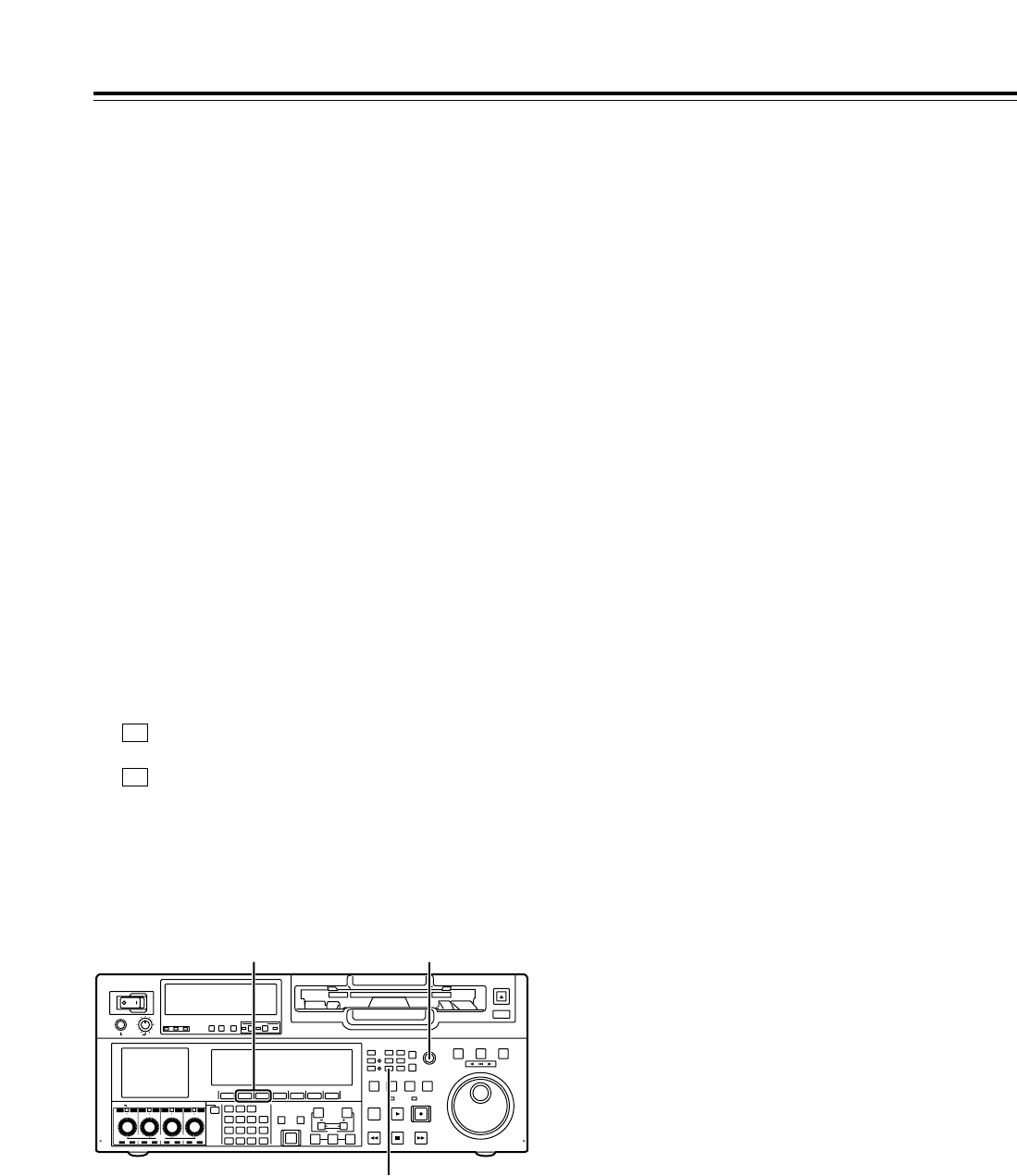
118
When a warning occurs in this VTR, the warning lamp
lights up.
When the DIAG menu is opened, a description of the
warning will appear on the front panel LCD area and
TV monitor. Also, when an abnormal operation is
detected in this VTR, the AUTO OFF lamp lights up,
and a message appears on the time code display
area.
DIAG menu
This displays the VTR information.
The VTR information includes the warning information
and hour-meter (usage time) information. The DIAG
menu appears on the front panel LCD display or on a
TV monitor when the TV monitor is connected to the
VIDEO OUT3 connector in the VTR’s connector area.
∫Displaying the DIAG menu
Error messages
1Press the DIAG button.
The DIAG menu screen is now displayed on the
TV monitor.
2The warning information is displayed by pressing
(WARN) on the time code display area, and
the hour-meter information is displayed by pressing
(HOURS) on this area.
The display of the hour-meter information is
scrolled using the ADJ dial.
F2
F1
3To exit the DIAG menu, press any other direct
menu button.
∫Displaying the warning information
• A warning message is displayed whenever a
warning occurs (the warning lamp lights up). When
no warnings have been detected, “NO WARNING”
is displayed.
• When a multiple number of warnings occur, the
descriptions of each warning can be checked by
turning the ADJ dial.
POWER
OFF
ON
HEADPHONES
PUSH
LOCK
FULL
CH CONDITION
MONITOR
FULL/FINE
REMOTE
LR
9P 50P
RS-232C
CH
12345678
CUE
XL/L/M
-
cassette
Do not insert S-cassette
without adapter
EJECT
AUDIO CH SELECT
SHIFT
ABC DEF GHI
JKL MNO PQRS
PREVIEW/
REVIEW
PRE-
ROLL
A IN A OUT
HOME RF1 ASSEM
ADJUST
SHTL
REV FWD
VARJOG
STAND BY
RECORDER INPUT CHECK
PLAYER
SERVO
EDIT PLAY REC
REW STOP FF
REC INHIBIT
PUSH-INTER
INSERT
RF2
VIDEO UNITY TC CUE
AUDIO UNITY DIAG MENU
TRIM
SET
IN
OUT
AUTO
EDIT
789
456BS
TUV WXYZ
123
ENT
0CT F
F1 F2 F3 F4 F5 F6
CH
1
CH
5
CH
2
CH
6
CH
3
CH
7
CH
4
CH
8
FULL
REC P8 REC P8 REC P8 REC P8
1
2
ADJ dial
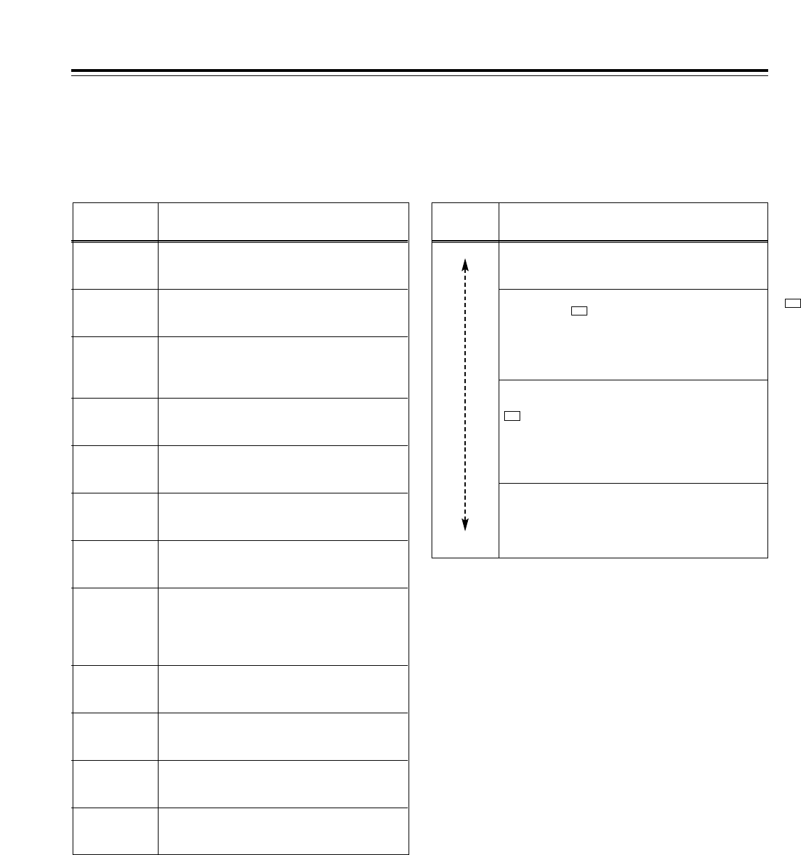
119
If “T&S&M” has been selected as the setup menu item
No.006 (DISPLAY SEL) setting, a message appears
in the mode display area whenever a warning or error
has occurred. When a multiple number of errors have
occurred, the one with the highest priority is displayed.
Error messages
Priority Display and description
Higher
Lower
Error messages (see error message table): When any
problem arises with the VTR’s operation, the AUTO OFF
lamp lights, and an error message is displayed.
INT SG: If, when “INT SG” has been selected as the audio
input setting by (VID IN) on the <VIDEO> menu or by the
<AUDIO> or <AUDIO SHIFT1> menu, and the EDIT button is
pressed, this message is displayed for the first two seconds
when editing is started. In the same way, it is displayed for the
first two seconds when recording is started.
F1
NO INPUT: If, when input signals (but not analog audio
signals) are not supplied to the input connector selected by
(VID IN) on the <VIDEO> menu or by the <AUDIO> or
<AUDIO SHIFT1> menu, the EDIT button is pressed, this
message is displayed for the first two seconds when editing
is started. In the same way, it is displayed for the first two
seconds when recording is started.
F1
Warning messages (see warning message table): When
a warning occurs in this VTR, the warning lamp lights, and a
warning message is displayed. When a multiple number of
warnings have occurred, the one with the highest priority is
displayed.
∫Displaying the hour-meter information
Turn the ADJ dial to move the cursor (¢), and the
description for the item where the cursor is located is
shown as a superimposed display.
<Note>
The resettable table hour-meter information items will
be reset by your dealer when maintenance or other
work is performed.
No./Item Description
H00
OPERATION
Displays in 1-hour increments the time during
which power has been supplied.
H01
DRUM RUN
Displays in 1-hour increments the amount of
time during which the drum has rotated.
H02
TAPE RUN
Displays in 1-hour increments the amount of time during
which the tape has been running in the FF, REW, PLAY,
SEARCH (JOG, VAR and SHTL), REC and EDIT modes (but
not in the JOG, VAR, SHTL or STILL mode).
H03
THREADING
Displays in 1-time increments the number of
times the tape has been threaded (loaded) and
unthreaded (unloaded).
H04
F LOADING
Displays in 1-time increments the number of
front loading operations.
H05
LCD ON
Displays in 1-hour increments the amount of
time during which the LCD monitor has lighted.
H15
LCD ON r
Displays in 1-hour increments the amount of
time during which the LCD monitor has lighted.
(Can be reset.)
H11
DRUM RUNr
Displays in 1-hour increments the amount of
time during which the drum has rotated.
(Can be reset.)
H13
THREADINGr
Displays in 1-time increments the number of
times the tape has been threaded (loaded) and
unthreaded (unloaded). (Can be reset.)
H30
POWER ON
Displays the number of times the power has
been turned on.
H12
TAPE RUNr
Displays in 1-hour increments the amount of time
during which the tape has been running in the FF,
REW, PLAY, SEARCH (JOG, VAR and SHTL),
REC and EDIT modes (but not in the JOG, VAR,
SHTL or STILL mode). (Can be reset.)
H14
F LOADINGr
Displays in 1-time increments the number of
front loading operations.
(Can be reset.)
F1

120
Higher
Lower
Error messages
Display •Description
•VTR operation and remedial action
Warning messages
Error messages
Priority •Display
•Description
•VTR operation and remedial action
SERVO NOT LOCKED
This is displayed when the servo is not locked for 3 or more
seconds during playback, recording or editing.
VTR: Operation continues.
• Check the tape. A tape recorded using a system which
does not allow playback may have been inserted
.
HIGH ERROR RATE
This is displayed when the error rate increases and
correction or interpolation is performed for either the video
or audio signals.
VTR: Operation continues.
• Clean the video heads.
LOW RF
This is displayed when a state in which the envelope level
has dropped to less than one-third of its normal level has
been detected for 1 or more seconds or when a state in
which the CTL signal level has dropped to less than one-
sixth of its normal level has been detected for 1 or more
seconds during playback, recording or editing.
• The CTL signal level is not detected during DV or
DVCAM playback.
• During recording or editing, the envelope level of only the
video simultaneous play heads is detected.
VTR: Operation continues.
• Clean the video heads and A/C head.
INVALID TC MODE (in 23/24 Hz or 25 Hz (HD or SD)
mode)
This is displayed during playback if the time code has been
recorded in the drop frame mode. The video output is
disturbed and the audio output is muted at the time code
drop point.
VTR: Operation continues.
• Check the tape. If a tape recorded using a variable frame
rate camera is to be played back in this VTR, the time
code must be recorded in the non-drop frame mode.
TC SEQUENCE UNMATCH (in 23/24 Hz or 25 Hz (HD or
SD) mode)
This is displayed during playback if the correlation between
the active frame information and time code is irregular. The
video output may not be uniform (the movements may not
be smooth).
VTR: Operation continues.
• Check the tape. The active frame (first frame where the
frame video is switched) information is recorded on a
tape recorded using a variable frame rate camera. When
such a tape is played back on this VTR, the 0 frame of
the time code must be detected at the active frame
position.
FAN STOP
This is displayed when the fan motor has stopped.
VTR: Operation continues (and a warning beep is sounded
regardless of the menu setting.)
• Check that no foreign matter has accumulated on the fan.
NO RF
This is displayed when a blank part of the tape lasting for 1
or more seconds has been detected during playback.
When all of the following conditions have been met, it will be
recognized as a blank part.
• When no signals are output from any of the heads
• When the playback data cannot be read
• When the CTL signal is not present
VTR: Operation continues.
• Check the tape. An unrecorded tape may have been
inserted.
CAP ROTA
TOO SLOW
If the rotational speed of the capstan motor is
abnormally slow, the AUTO OFF lamp lights, and the
message display blinks.
VTR: Stops.
• Set the POWER switch to OFF and then back to ON
again.
CAP TENSION
ERROR
If an abnormal tension is detected at the supply side in
the capstan mode, the AUTO OFF lamp lights, and the
message display blinks.
VTR: Stops.
• Set the POWER switch to OFF and then back to ON
again.
DEW
When condensation has been detected, the AUTO OFF
lamp lights, the message display blinks, and the VTR
transfers to the EJECT mode. After the tape has been
ejected, the drum continues to rotate in order to dry out
the condensation.
When the condensation has cleared, the AUTO OFF
lamp goes off, the message display is cleared, and the
VTR is ready for operation again.
• When condensation is detected in the EJECT mode,
the drum starts rotating as soon as it is detected.
• When condensation is detected while a cassette is
inserted, the drum stops rotating and starts rotating
again after the tape has been ejected.
VTR: EJECT
• Wait with the power on.
DRUM ROTA
TOO FAST
If the rotational speed of the cylinder motor is
abnormally high, the AUTO OFF lamp lights, and the
message display blinks.
VTR: Stops.
• Set the POWER switch to OFF and then back to ON
again.
DRUM ROTA
TOO SLOW
If the rotational speed of the cylinder motor is
abnormally slow, the AUTO OFF lamp lights, and the
message display blinks.
VTR: Stops.
• Set the POWER switch to OFF and then back to ON
again.
E-FF
If the tape start and tape end are detected at the same
time either during or after loading, the AUTO OFF lamp
lights, and the message display blinks.
VTR: Stops.
• Set the POWER switch to OFF and then back to ON
again.
FRONT LOAD
ERROR
If the take-up reel has turned without engaging the tape
for a specific period of time during the tape start or end
processing operation while loading is being performed
(at the half position), the AUTO OFF lamp lights, and
the message display blinks.
VTR: Stops.
• Set the POWER switch to OFF and then back to ON
again.

121
Error messages
Display •Description
•VTR operation and remedial action
T REEL
TORQUE ERR
If an abnormal torque applied to the take-up reel motor
is detected, the AUTO OFF lamp lights, and the
message display blinks.
VTR: Stops.
• Set the POWER switch to OFF and then back to ON
again.
S REEL
TORQUE ERR
If an abnormal torque applied to the supply reel motor
is detected or if an abnormal current flowing to the
current-sensing resistor is detected, the AUTO OFF
lamp lights, and the message display blinks.
VTR: Stops.
• Set the POWER switch to OFF and then back to ON
again.
If the error message display persists even after the
VTR has been shut down and started up again,
consult your dealer.
UNLOAD
ERROR
If the tape has not been wound up during unloading,
the AUTO OFF lamp lights, and the message display
blinks.
VTR: Stops.
• Set the POWER switch to OFF and then back to ON
again.
WINDUP
ERROR
If, after the total tape amount has been detected, the
amount of tape wound up onto the take-up reel and the
amount of tape supplied by the supply reel differ to an
abnormal extent while the tape is traveling, the AUTO
OFF lamp lights, and the message display blinks.
VTR: Stops.
• Set the POWER switch to OFF and then back to ON
again.
W-UP REEL
NOT ROTA
If, after the cassette has been inserted, the tape take-
up reel has not wound up the tape while the total tape
amount is not detected and while the tape is traveling,
the AUTO OFF lamp lights, and the message display
blinks.
VTR: Stops.
• Set the POWER switch to OFF and then back to ON
again.
Error messages
S-FF/REW
TIMEOVER
When the tape start or end processing operation is not
completed, the AUTO OFF lamp lights, and the
message display blinks.
VTR: Stops.
• Set the POWER switch to OFF and then back to ON
again.
T REEL ROTA
TOO FAST
If the take-up reel motor rotates at an abnormally fast
rate, the AUTO OFF lamp lights, and the message
display blinks.
VTR: Stops.
• Set the POWER switch to OFF and then back to ON
again.
S REEL ROTA
TOO FAST
If the supply reel motor rotates at an abnormally fast
rate, the AUTO OFF lamp lights, and the message
display blinks.
VTR: Stops.
• Set the POWER switch to OFF and then back to ON
again.
Display •Description
•VTR operation and remedial action
FRONT LOAD
MOTOR
If the cassette fails to move up even after 6 seconds
have elapsed since the VTR transferred to the EJECT
mode, the AUTO OFF lamp lights, and the message
display blinks.
<Note>
If the cassette fails to move down even after 6 seconds
have elapsed since the cassette was inserted, the VTR
transfers to the EJECT mode.
VTR: Stops.
• Set the POWER switch to OFF and then back to ON
again.
LOADING
MOTOR
If the unloading operation fails to be completed within 6
seconds, the AUTO OFF lamp lights, and the message
display blinks.
<Note>
If the loading operation fails to be completed within 6
seconds, the VTR transfers to the EJECT mode
(unloading mode).
VTR: Stops.
• Set the POWER switch to OFF and then back to ON
again.
REEL DIR
UNMATCH
If the take-up reel motor is running in the reverse
direction, the AUTO OFF lamp lights, and the message
display blinks.
VTR: Stops.
• Set the POWER switch to OFF and then back to ON
again.
REEL
TENSION
ERROR
If an abnormal tension at the supply side is detected in
the reel mode, the AUTO OFF lamp lights, and the
message display blinks.
VTR: Stops.
• Set the POWER switch to OFF and then back to ON
again.
SERVO COMM
ERROR
When the servo microcomputer does not follow the
instructions of the system control microcomputer even
after 10 seconds have elapsed, the AUTO OFF lamp
lights, and the message display blinks.
VTR: Stops.
• Set the POWER switch to OFF and then back to ON
again.
SERVO
CONTROL
ERROR
When there is no response from the servo
microcomputer for 1 or more seconds, the AUTO OFF
lamp lights, and the message display blinks.
VTR: Stops.
• Set the POWER switch to OFF and then back to ON
again.
SERVO
ERROR
When only the servo microcomputer was reset in an
instantaneous power failure, etc., the AUTO OFF lamp
lights, and the message display blinks.
VTR: Stops.
• Set the POWER switch to OFF and then back to ON
again.
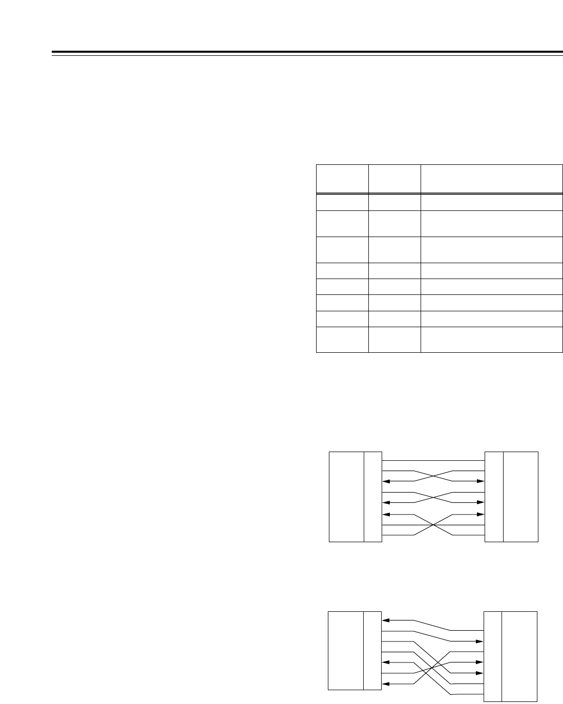
122
The VTR can be operated by commands when the
RS-232C interface is used. (Refer to the command
tables on page 125 and 126.)
∫Condition for acknowledging
commands from RS-232C interface
Setup menu item No.204 (RS232C SEL): ON
If the above condition is not met,
[ACK]+[STX]ER001[EXT] is returned to the external
component. Whether [ACK] is returned depends on
the setting which has been selected for setup menu
item No.209 (RETURN ACK).
Hardware specifications
External interface specifications
RS-232C interface
•Connector pin specifications
Connector: D-SUB 25-pin
(crossover cable supported)
Pin No. Signal Description
1FG Protective ground (frame ground)
2RXD Received data (data is sent to PC)
3TXD Transmitted data (data is received
from PC)
4CTS Clear to send (shorted with pin 5)
5RTS Request to send (shorted with pin 4)
6DTR Data terminal ready (no processing)
7SG Signal ground
20 DSR Data set ready (+ voltage output after
communication enable status)
•Example of connection with controller (PC)
(Using crossover cable with D-SUB 25-pin
connectors)
PC side
(D-SUB 25-pin connector)
VTR side
FG
TXD
RXD
RTS
CTS
DSR
SG
DTR
1
2
3
4
5
6
7
20
FG
RXD
TXD
CTS
RTS
DTR
SG
DSR
1
2
3
4
5
6
7
20
(Using crossover cable with D-SUB 9-pin and D-
SUB 25-pin connectors)
PC side
(D-SUB 9-pin connector)
VTR side
RXD
TXD
DTR
SG
DSR
RTS
CTS
2
3
4
5
6
7
8
FG
RXD
TXD
CTS
RTS
DTR
SG
DSR
1
2
3
4
5
6
7
20
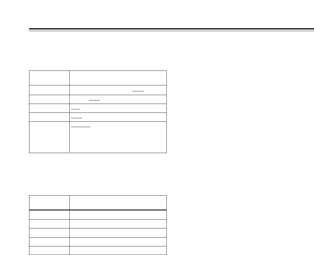
123
Software specifications (protocol)
1. Communication parameters
RS-232C interface
Communication
system Asynchronous, full duplex
Transfer rate 300, 600, 1200, 2400, 4800 or 9600 bps
Bit length 7 bits or 8 bits
Stop bit 1 bit or 2 bits
Parity bit None, odd or even
ACK code Returned or not returned
<Note>
ACK is the code which is returned from the
VTR to the controller when data has been
successfully sent from the controller.
The underlining (__) denotes the factory setting mode.
Communication
parameter Setup menu item
Transfer rate No.205 BAUD RATE
Bit length No.206 DATA LENGTH
Stop bit No.207 STOP BIT
Parity bit No.208 PARITY
ACK code No.209 RETURN ACK
Any changes to the settings can be made using the
setup menu items listed below.
2. Send format
[controller (PC) >VTR]
∫Data format
[STX] [command] [:] [data] [ETX]
02h XX XX XX 3Ah XX.....XX 03h
20H<XX<7FH
(XX=ASCII code: symbols, numbers, upper-
case letters)
[command]:
This is the command identifier (3 bytes).
A 3-byte identifier (ASCII code: symbols,
numbers, upper-case letters) is sent as the
command.
[:]
The colon is the code serving as a delimiter
between the command and data.
[data]:
Data (ASCII code: symbols, numbers, upper-
case letters) can be added in the number of
bytes required.
∫Outline of procedure for sending data from
controller
1The send command starts with STX (start of
text = 02h). The command is then identified
by COMMAND which follows, and the data is
added as required.
The command ends with ETX (end of text =
03h).
2When a different command is to be sent, a
response is awaited from the VTR, and then
the command is sent. (See page 124.)
3If STX is sent again before ETX is sent, the
receive data buffer inside the VTR is cleared.
A command error is returned to the
controller, and the data is newly processed
with STX which was received again at the
head.

124
RS-232C interface
3. Return format
[VTR >controller (PC)]
The following responses are made to the
commands. If necessary, more than one
response is made.
∫When the communication has ended
successfully
1. The receive completion message is returned.
[ACK]
06h
2. The execution completion message is
returned.
[STX] [command] [data] [ETX]
02h XX XX XX XX.....XX 03h
[command]:
This is the message (data) which is returned
or the execution completion message
identifier.
[data]:
This is the data to be returned. It can be
omitted.
Example:
Send command . . . . . . . . . . . . . . . . . . . . . . . . . . . . . . . . .
Return message (data)
[
STX] OPL [ETX] . . . . . . . . . . . . . . . . . . . . . . . . . . . . . .
5
[ACK] [STX] OPL [ETX]
∫When the communication has ended
unsuccessfully
[NACK]
15h
∫When processing is not possible due to
incorrect data or problem with the VTR
1. The receive completion message is returned.
[ACK]
06h
2. An error code is returned.
[STX] [E R N1N2N3][ETX]
02h
Error code
03h
4. Error code table
ER001: Invalid command
• Unsupported command received
• Command execution error
ER002: Parameter error
ER102: VTR mode error
(front loading motor)
ER103: VTR mode error (loading motor)
ER104: VTR mode error (drum, capstan system)
ER105: VTR mode error (reel system)
ER106: VTR mode error (tension system)
ER108: VTR condensation error
ER1FF: VTR system error
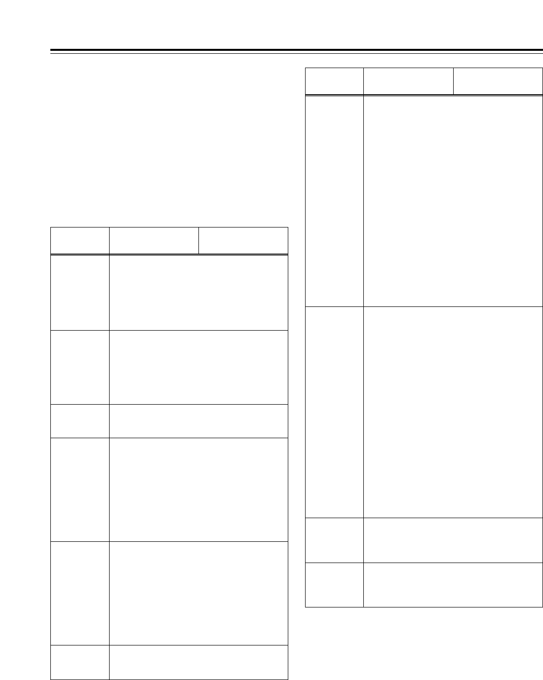
125
RS-232C interface
5. Command table
∫Commands relating to operation control
<Notes>
• As the return (completion) message, [ACK] is
returned when data is received, and only the
execution message which is subsequently
returned is listed in the table.
• If a command not listed in the table is received,
ER001 (invalid command) is returned after
[ACK].
VTR
operation Send command
STOP
[STX] OSP [ETX] 45 [STX] OSP [ETX]
This command is for stopping the tape transport.
The resulting output picture and sound statuses
differ according to the setting selected for the
setup menu item No.105 (AUTO EE SEL).
For details, refer to the setup menus.
Return (completion)
message
STANDBY
OFF
[STX] OBF [ETX] 45 [STX] OBF [ETX]
This command is for setting the VTR to standby
OFF.
STANDBY ON
[STX] OBN [ETX] 45 [STX] OBN [ETX]
This command is for setting the VTR to standby
ON.
VTR
operation Send command
SHTL
FORWARD
[STX] OSF:data [ETX]
45 [STX] OSF [ETX]
This is the forward direction shuttle command.
data = n: speed data
0: STILL
1: k0.03
2: k0.1
3: k0.2
4: k0.5
5: k1
6: k2.0
(1.85kfor formats other than
DVCPROHD-LP)
7: k4.9
8: k9.8
9: k16
A: k32
<Note>
The 16kand 32kspeeds differ according to the
setting selected for setup menu item No.101
(SHTL MAX).
Return (completion)
message
SHTL
REVERSE
[STX] OSR:data [ETX]
45 [STX] OSR [ETX]
This is the reverse direction shuttle command.
data = n: speed data
0: STILL
1: k0.03
2: k0.1
3: k0.2
4: k0.5
5: k1
6: k2.0
(1.85kfor formats other than
DVCPROHD-LP)
7: k4.9
8: k9.8
9: k16
A: k32
<Note>
The 16kand 32kspeeds differ according to the
setting selected for setup menu item No.101
(SHTL MAX).
EJECT
[STX] OEJ [ETX] 45 [STX] OEJ [ETX]
This command is for ejecting the cassette tape.
The resulting output picture and sound statuses
differ according to the setting selected for the
setup menu item No.105 (AUTO EE SEL).
For details, refer to the setup menus.
PLAY
[STX] OPL [ETX] 45 [STX] OPL [ETX]
This command is for starting playback.
REWIND
[STX] ORW [ETX] 45 [STX] ORW [ETX]
This command is for rewinding the tape. The
resulting output picture and sound statuses differ
according to the setting selected for the setup
menu item No.105 (AUTO EE SEL).
The maximum speed differs according to the
setting selected for the setup menu item No.102
(FF. REW MAX).
For details, refer to the setup menus.
FAST
FORWARD
[STX] OFF [ETX] 45 [STX] OFF [ETX]
This command is for fast forwarding the tape.
The resulting output picture and sound statuses
differ according to the setting selected for the
setup menu item No.105 (AUTO EE SEL).
The maximum speed differs according to the
setting selected for the setup menu item No.102
(FF. REW MAX).
For details, refer to the setup menus.
REC
[STX] ORC [ETX] 45 [STX] ORC [ETX]
This command is for starting recording.

126
RS-232C interface
∫Commands relating to inquiries
<Notes>
• In terms of the return (completion) message,
[ACK] is returned when data is received, and
only the execution message which is
subsequently returned is listed in the table.
• In the case of commands not listed in the table
below, ER001 (invalid command) is returned
after [ACK].
VTR
operation Send command
CTL/TC DATA
REQUEST
[STX] QCD [ETX] 45 [STX] CD data [ETX]
This command is for inquiring about the counter
value.
data = f w gh mm ss ff
f=F
w=S
gh =
With CTL:
g = SP(20h): for a plus display
j(2Dh): for a minus display
h = 0 to 9: hours
With TC:
gh = 00 to 23: hours
mm = 00 to 59: minutes
ss = 00 to 59: seconds
(525i system)
ff = 00 to 29: frames
<Note>
CTL or TC is returned, whichever corresponds to
the front display mode.
Return (completion)
message
STATUS
REQUEST
[STX] QOP [ETX] 45 [STX] 222 [ETX]
This command is for inquiring about the VTR’s
operation mode.
222 = OEJ: EJECT
OFF: FAST FORWARD
OPL: PLAY
ORC: REC
ORW: REWIND
OSP: STOP (including STANDBY ON)
SRS: (IN/OUT) PREROLL
OBF: STAND BY OFF
OSF: SHTL FORWARD
OSR: SHTL REVERSE
OJG: JOG FORWARD/REVERSE
OSW: VAR FORWARD/REVERSE
EAE: AUTO EDIT
EON: EDIT ON (MANUAL EDIT)
EPV: PREVIEW
ERV: REVIEW
ID (VTR No.)
REQUEST
[STX] QID [ETX] 45 [STX] data [ETX]
This command is for inquiring about the VTR
used.
data = AJ-HD1700

127
RS-232C interface
∫Microsoft QuickBASIC sample program
CLS
STX$ = CHR$(&H2): ETX$ = CHR$ (&H3): NAK$ = CHR$(15): ACK$ = CHR$(&H6)
PRINT "*** RS-232C COMMUNICATION SAMPLE PROGRAM ***"
PRINT "Type Command 'QUIT' to quit."
PRINT
REM *** Communication Port Initial & Open ***
REM Port 1,9600Bps,No parity,8 bit data,1 stop bit
OPEN "COM1:9600,N,8,1" FOR RANDOM AS #1 LEN = 256
REM *** Input Command & Send Command ***
SendCmd:
INPUT "Input Command ="; SEND$
IF SEND$ = "QUIT" THEN GOTO ProgEnd
PRINT #1, STX$ + SEND$ + ETX$
REM *** Wait for Receive Command ***
WHILE LOC(1) = 0
WAITKEY$ = INKEY$
IF WAITKEY$ = "Q" THEN PRINT "*** Quit ***": GOTO ProgEnd
WEND
REM *** Receive Command ***
RecvCmd:
RECV$ = INPUT$(1, #1)
IF RECV$ = STX$ THEN RECV$ = "[Stx]"
IF RECV$ = ACK$ THEN RECV$ = "[Ack]"
IF RECV$ = NAK$ THEN RECV$ = "[Nak]"
IF RECV$ = ETX$ THEN BUFFER$ = BUFFER$ + "[Etx]": GOTO DispOut
BUFFER$ = BUFFER$ + RECV$
GOTO RecvCmd
REM *** Output Receive Command ***
DispOut:
PRINT "Receive Command ="; BUFFER$
PRINT
BUFFER$ = ""
GOTO SendCmd
REM *** End Program ***
ProgEnd:
CLOSE
END
Microsoft QuickBASIC is a trademark of Microsoft Corporation.
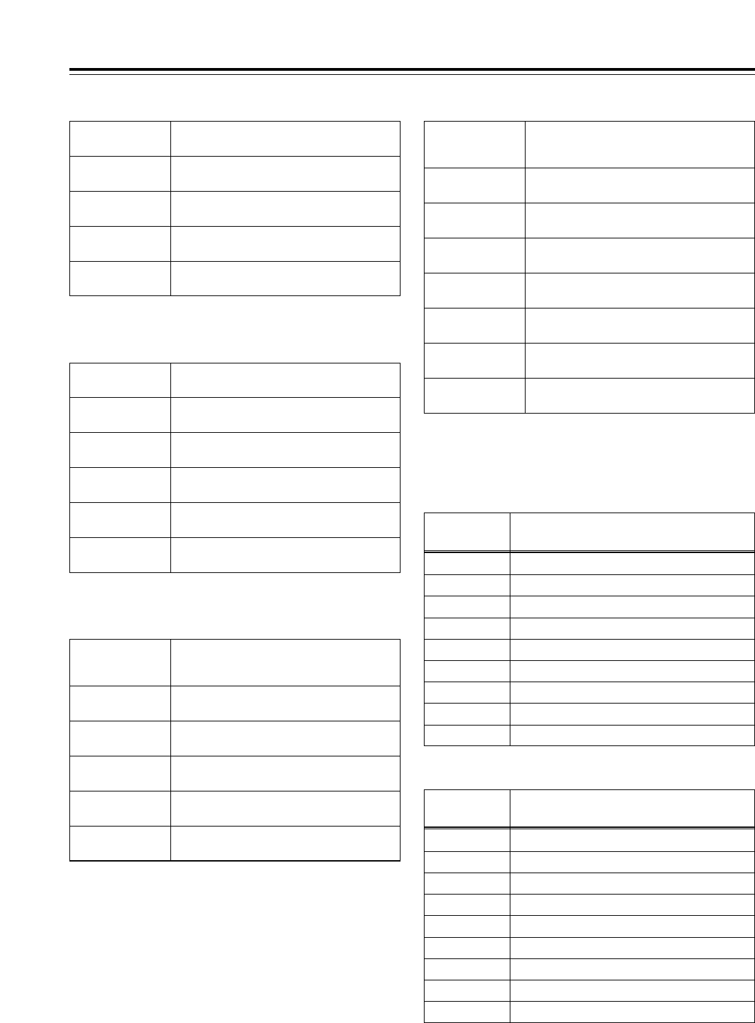
128
Connector signals
VIDEO IN
HD SERIAL IN
(DIGITAL) BNC k1, active-through (BNC k1)
HD REF IN BNC k2, loop-through, 75™termination
switch provided
SD REF IN BNC k2, loop-through, 75™termination
switch provided
SD SERIAL IN
(DIGITAL) BNC k1, active-through (BNC k1) (board,
option)
SDTI IN BNC k1 (board, option)
VIDEO OUT
HD SERIAL OUT
(DIGITAL)
BNC k 4
SD SERIAL OUT
(DIGITAL)
BNC k 2
VIDEO OUT BNC k 3
HD REF OUT BNC k 1
SD REF OUT BNC k 1
SDTI OUT BNC k1 (board, option)
AUDIO IN
HD SERIAL IN
(DIGITAL) BNC k1, active-through (BNC k1)
AUDIO IN
(DIGITAL) BNC k 4 (CH1/CH2, CH3/CH4, CH5/CH6,
CH7/CH8), AES/EBU format
AUDIO IN
(ANALOG) XLR k 4 (CH1, CH2, CH3, CH4)
CUE IN XLR k 1
TIME CODE IN XLR k 1
SD SERIAL IN
(DIGITAL) BNC k1, active-through (BNC k1) (board,
option)
AUDIO OUT
HD SERIAL OUT
(DIGITAL)
BNC k 4
AUDIO OUT
(DIGITAL)
BNC k 4 (CH1/CH2, CH3/CH4, CH5/CH6,
CH7/CH8), AES/EBU format
AUDIO OUT
(ANALOG) XLR k 4 (CH1, CH2, CH3, CH4)
CUE OUT XLR k 1
TIME CODE OUT XLR k 1
MONITOR OUT XLR k 2 (L, R)
HEADPHONES
(front) 1/4-inch (6.5 mm)
SD SERIAL OUT
(DIGITAL)
BNC k 2
RS-422A REMOTE (9P)
OREMOTE IN/OUT
Pin No. Signal
1FRAME GROUND
2TRANSMIT A
3RECEIVE B
4RECEIVE COMMON
5====
6TRANSMIT COMMON
7TRANSMIT B
8RECEIVE A
9FRAME GROUND
OREMOTE OUT
Pin No. Signal
1FRAME GROUND
2RECEIVE A
3TRANSMIT B
4TRANSMIT COMMON
5====
6RECEIVE COMMON
7RECEIVE B
8TRANSMIT A
9FRAME GROUND
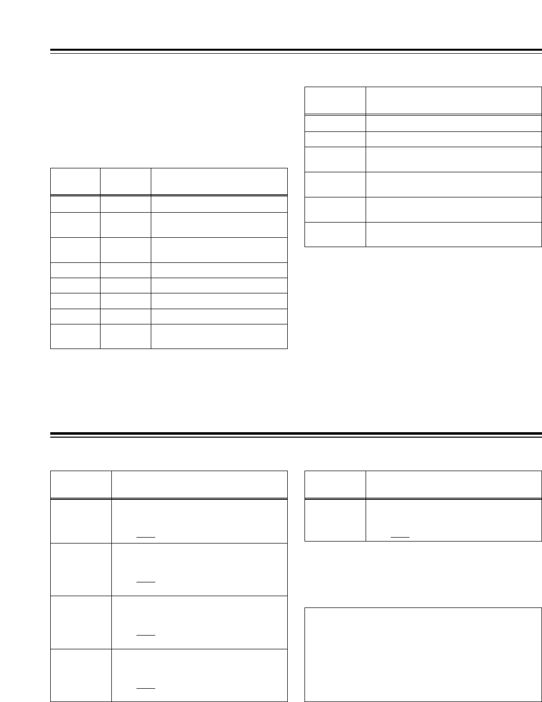
CUE INPUT IMPEDANCE SW
This sets the CUE input impedance.
HIGH/600™
129
Connector signals
PARALLEL REMOTE (50P)
Refer to 50P IN/OUT ASSIGN on the function menu
(page 75) for the connection pin signals.
ENCODER REMOTE(15P)
Pin No. Signal
1FRAME GROUND
4REM (G)
7REM RX (X)
REMOTE CONTROL PROTOCOL RECEIVE
8REM TX (X)
REMOTE CONTROL PROTOCOL TRANSMIT
14 REM RX (Y)
REMOTE CONTROL PROTOCOL RECEIVE
15 REM TX (Y)
REMOTE CONTROL PROTOCOL TRANSMIT
RS-232C
(D-SUB 25-pin, crossover cable supported)
Pin No. Signal Description
1FG Protective ground (frame ground)
2RXD Received data (data is sent to PC)
3TXD Transmitted data (data is received
from PC)
4CTS Clear to send (shorted with pin 5)
5RTS Request to send (shorted with pin 4)
6DTR Data terminal ready (no processing)
7SG Signal ground
20 DSR Data set ready (+ voltage output after
communication enable status)
Printed circuit boards
F1 board (ADDA)
Switch No. What is set
SW1
SW101 AUDIO INPUT IMPEDANCE SW
This sets the CH2 audio input impedance.
HIGH/600™
SW201 AUDIO INPUT IMPEDANCE SW
This sets the CH3 audio input impedance.
HIGH/600™
SW301 AUDIO INPUT IMPEDANCE SW
This sets the CH4 audio input impedance.
HIGH/600™
The underlining (__) denotes the factory setting mode.
AUDIO INPUT IMPEDANCE SW
This sets the CH1 audio input impedance.
HIGH/600™
H3 board (CUE)
Switch No. What is set
SW101
CAUTION:
These servicing instructions are for use by
qualified service personnel only. To reduce the
risk of fire or electric shock do not perform any
servicing other than that contained in the
operating instructions unless you are qualified
to do so.

130
[GENERAL]
indicates the safety information.
Power supply: AC 100–240V, 50–60 Hz (AJ-HD1700P)
AC 100–240V, 50–60 Hz (AJ-HD1700E)
Power consumption: 240W
Operating ambient temperature:
41xF to 104xF (5xC to 40xC)
Operating ambient humidity:
10% to 80% (no condensation)
Weight:
Approx. 48.4 lbs (22 kg)
Dimensions (W kH kD):
16-3/4 (max. 17-3/16 ) k6-15/16 k17-11/16 inches
(not including supporting feet, jacks and connectors, JOG
dial and fan)
424 (max. 435.4) k175.2 k448.9 mm
Recording format:
DVCPRO HD-LP
Video signals recorded:
1080i (50/59.94/60 Hz switchable)
720p (59.94/60 Hz switchable)
480i/59.94 Hz
576i/50 Hz (when optional board AJ-UC1700G is installed)
Audio signals recorded:
48 kHz, 16 bits, 8 channels
Recording tracks:
Digital video/audio:
helical tracks
(Time code is recorded in sub-code area.)
Cue track:
1 track
Control track:
1 track
Tape speed:
67.64 mm/sec. (in 59.94 Hz mode)
67.70 mm/sec. (in 60 or 50 Hz mode)
Tape used:
Metal tape
Recording time:
126 minutes (using XL cassette)
92 minutes (using L cassette)
32 minutes (using M cassette)
FF/REW time:
Approx. 1 min. 30 sec. (when XL cassette is used and
i100kor j100kspeed is selected)
Search speed:
d100k
Digital slow:
j1kto i2k(when playing back tapes recorded using the
DVCPRO HD-LP format)
j1kto i1.1k(when playing back tapes recorded using
any other format)
Editing accuracy:
d0 frames (when time code is used, in 50 Hz, 59.94 Hz or
60 Hz mode)
Tape timer accuracy:
d1 frame (when continuous CTL signal is used)
Servo lock time:
Less than 0.3 sec. (from standby ON)
Specifications
[VIDEO]
Sampling frequencies:
Y: 74.25 MHz, Pb/Pr: 37.125 MHz
Quantizing:
8 bits
Video compression method:
DCT ivariable length code
Video compression rate:
1/6.7
Error correction:
Reed-Solomon product code
Video recording bit rate:
100 Mbps
Video Input Connectors
HD serial digital input:
BNC k1 (complies with SMPTE 292M standard),
BNC k1 (active-through)
SD serial digital input (option):
BNC k1 (complies with SMPTE 259M-C standard),
BNC k1 (active-through)
SDTI input (option):
BNC k1 (complies with SMPTE 305M/SMPTE 321M
standards)*
HD reference input:
BNC k2 (loop-through), 75™ON/OFF selectable
SD reference input:
BNC k2 (loop-through), 75™ON/OFF selectable
Video Output Connectors
HD serial digital output:
BNC k3 (complies with SMPTE 292M standard),
BNC k1 (monitor output with superimposed display)
SD serial digital output:
BNC k1 (complies with SMPTE 259M-C/SMPTE 294M
standards),
BNC k1 (monitor output with superimposed display)
SDTI output (option):
BNC k1 (complies with SMPTE 305M/SMPTE 321M
standards)
HD reference output:
BNC k1
SD reference output:
BNC k1
Analog composite output:
BNC k3, VIDEO 1, VIDEO 2 (WFM OUT), VIDEO 3
(superimposed ON/OFF), output during SD playback or
during down-conversion
* The optional AJ-UC1700G SD serial digital input board and
optional AJ-YAC150P SDTI input board cannot be installed at
the same time. Install one or the other.
Loading time:
Approx. 4 sec.
Audio split editing:
Provided

131
Specifications
[VIDEO]
Video signal adjustment ranges
• Component style
HD/SD SDI, composite output Y gain:
j¶ to i3 dB
HD/SD SDI, composite output Pb gain:
j¶ to i3 dB
HD/SD SDI, composite output Pr gain:
j¶ to i3 dB
HD/SD SDI, composite output Y black level:
w10%
• Composite style
HD/SD SDI, composite output video gain:
j¶ to i6 dB
HD/SD SDI, composite output chroma gain:
j¶ to i3 dB
HD/SD SDI, composite output chroma phase (*1):
w30x
HD/SD SDI, composite output Y setup:
w10%
• System phase
HD SDI output system phase
w5.5 H (w12100 sample, 13.5 nS step, 59/60Hz)
(w14520 sample, 50/25Hz)
(w15125 sample, 23/24Hz)
SD SDI output system phase
w5.5 H (w9438 sample, 480i: 37nS step,
480p: 54nS step)
(w9504 sample, 576i)
Composite video output system phase
w5.5 H (w9438 sample, 37nS step, 59Hz)
(w9504 sample, 37nS step, 50Hz)
Composite video output SC phase:
w180xor more
*1: Only the SD SDI composite output of SD tape playback is valid
in the 50 Hz or 25 Hz mode.
[AUDIO]
Cue Track
Frequency response:
300 Hz to 6 kHz w3 dB
Audio Input Connectors
Analog input (CH1 to CH4)
XLR k4, 600™/high impedance (selectable), i4, 0, j20
dBu selectable
Digital input (CH1/CH2, CH3/CH4, CH5/CH6, CH7/CH8)
BNC k4, AES/EBU format
HD serial digital input
BNC k1 (complies with SMPTE 292M/SMPTE 299M
standards)
BNC k1 (active-through)
SD serial digital input (option)
BNC k1 (complies with SMPTE 259M-C/SMPTE 272M-A
standards)
BNC k1 (active-through)
Cue track input
XLR k1, 600™/high impedance (selectable), i4, 0, j20,
j60 dBu selectable
Audio output Connectors
Analog output (CH1 to CH4)
XLR k4, low impedance, i4, 0, j20 dBu selectable
Digital output (CH1/CH2, CH3/CH4, CH5/CH6, CH7/CH8)
BNC k4, AES/EBU format
HD serial digital output
BNC k4 (complies with SMPTE 292M/SMPTE 299M
standards)
SD serial digital output
BNC k2 (complies with SMPTE 259M-C/SMPTE
294M/SMPTE 272M-A standards)
Cue track output
XLR k1, low impedance (selectable), i4, 0, j20 dBu
selectable
Monitor output
XLR k2, low impedance (selectable), i4, 0, j20 dBu
selectable
Headphone output
1/4-inch phone (6.5 mm), 8™, variable level
Audio level adjustment range
j¶ to i12 dB
[AUDIO]
Digital Audio
Sampling frequency:
48 kHz (synchronized with video)
Quantizing:
16 bits
Frequency response:
20 Hz to 20 kHz w10 dB (at reference level)
Dynamic range:
Better than 90 dB (1 kHz, emphasis OFF)
Distortion:
Less than 0.05% (1 kHz, emphasis OFF, reference level)
Crosstalk:
Less than j80 dB (1 kHz, between 2 channels)
Wow & flutter:
Below measurable limit
Headroom:
20 dB (AJ-HD1700P)
18 dB (AJ-HD1700E)

132
Specifications
[OPTIONAL ACCESSORIES]
Rack-mounting adapters:
AJ-MA75P
SD-HD format converter board:
AJ-UC1700G
Encoder/decoder board supporting DVCPRO HD bank
data:
AJ-VNC150P
SDTI interface board:
AJ-YAC150P
Weight and dimensions shown are approximate.
Specifications are subject to change without notice.
[OTHER INPUT/OUTPUT SIGNALS]
Time code input
XLR k1, 0.5 to 8.0 Vp-p, 10 k™
Time code output
XLR k1, low impedance
2.0 w0.5 Vp-p, (with 600™load)
RS-422A input
D-sub 9-pin, RS-422A interface
RS-422A output
D-sub 9-pin, RS-422A interface
RS-232C
D-sub 25-pin, RS-232C interface
Parallel input/output
D-sub 50-pin
Encoder remote
D-sub 15-pin

133

F0703H1@32
PANASONIC BROADCAST & TELEVISION SYSTEMS COMPANY
UNIT COMPANY OF MATSUSHITA ELECTRIC CORPORATION OF AMERICA
Executive Office:
One Panasonic Way 4E-7, Secaucus, NJ 07094 (201) 348-7000
EASTERN ZONE:
One Panasonic Way 4E-7, Secaucus, NJ 07094 (201) 348-7621
Southeast Region:
1225 Northbrook Parkway, Ste 1-160, Suwanee, GA 30024 (770) 338-6835
Central Region:
1707 N Randall Road E1-C-1, Elgin, IL 60123 (847) 468-5200
WESTERN ZONE:
3330 Cahuenga Blvd W., Los Angeles, CA 90068 (323) 436-3500
Government Marketing Department:
52 West Gude Drive, Rockville, MD 20850 (301) 738-3840
Broadcast PARTS INFORMATION & ORDERING:
9:00 a.m. – 5:00 p.m. (EST) (800) 334-4881/24 Hr. Fax (800) 334-4880
Emergency after hour parts orders (800) 334-4881
TECHNICAL SUPPORT:
Emergency 24 Hour Service (800) 222-0741
Panasonic Canada Inc.
5770 Ambler Drive, Mississauga, Ontario L4W 2T3 (905) 624-5010
Panasonic de Mexico S.A. de C.V.
Av angel Urraza Num. 1209 Col. de Valle 03100 Mexico, D.F. (52) 1 951 2127
Panasonic Sales Company
Division of Matsushita Electric of Puerto Rico Inc.
San Gabriel Industrial Park, 65th Infantry Ave., Km. 9.5, Carolina, Puerto Rico 00630 (787) 750-4300
Panasonic Broadcast Europe
Panasonic Broadcast Europe Ltd
West Forest Gate, Wellington Road, Wokingham, Berkshire RG40 2AQ U.K. Tel: 0118 902 9200
Panasonic Broadcast Europe GmbH
Hagenauer Str. 43, 65203 Wiesbaden-Biebrich Deutschland Tel: 49-611-1816-0
Printed in Japan
C 2003 Matsushita Electric Industrial Co., Ltd. All rights reserved.
