Panasonic AW E600 E600P Cover User Manual To The 8d43d7d3 4182 0604 3572 689c39a15b15
User Manual: Panasonic AW-E600 to the manual
Open the PDF directly: View PDF ![]() .
.
Page Count: 55
- AW-E600
- CONTENTS
- PREFACE
- FEATURES
- SPECIAL NOTES ON OPERATION
- PRECAUTIONS
- MAJOR OPERATING CONTROLS AND THEIR FUNCTIONS
- MOUNTING
- FLANGE BACK ADJUSTMENT (FOR ZOOM LENS)
- IRIS GAIN CONTROL IN A LENS
- CONNECTIONS
- ADJUSTMENT
- USE MODE SETTING
- MENU ITEM SETTING
- SETTING TO INITIAL SET
- APPEARANCE
- SPECIFICATIONS
- STANDARD ACCESSORIES
- OPTIONAL ACCESSORIES
Convertible Camera
AW-E600
Before attempting to connect or operate this product,
please read these instructions completely.
This Class A digital apparatus complies with Canadian
ICES-003.
Cet appareil numérique de la classe A est conforme à la
norme NMB-003 du Canada.
WARNING:
TO PREVENT FIRE OR SHOCK HAZARD, DO NOT EXPOSE THIS APPLIANCE TO RAIN OR MOISTURE.
The lightning flash with arrowhead sym-
bol, within an equilateral triangle, is
intended to alert the user to the pres-
ence of uninsulated "dangerous voltage"
within the product's enclosure that may
be of sufficient magnitude to constitute a
risk of electric shock to persons.
The exclamation point within an equilat-
eral triangle is intended to alert the user
to the presence of important operating
and maintenance (servicing) instructions
in the literature accompanying the appli-
ance.
The information marking of this product may be found on the
bottom of the unit.
The serial number of this product may be found on the bot-
tom of the unit.
You should note the serial number of this unit in the space
provided and retain this book as a permanent record of your
purchase to aid identification in the event of theft.
Model No.
Serial No.
CAUTION:
TO REDUCE THE RISK OF ELECTRIC SHOCK, DO
NOT REMOVE COVER (OR BACK). NO USER SER-
VICEABLE PARTS INSIDE.
REFER SERVICING TO QUALIFIED SERVICE PER-
SONNEL.
CAUTION
RISK OF ELECTRIC SHOCK
DO NOT OPEN
SA 1965
SA 1966
For CANADA
NOTE: This equipment has been tested and found to com-
ply with the limits for a Class A digital device, pursuant to
part 15 of the FCC Rules. These limits are designed to pro-
vide reasonable protection against harmful interference
when the equipment is operated in a commercial environ-
ment. This equipment generates, uses, and can radiate
radio frequency energy and, if not installed and used in
accordance with the instruction manual, may cause harmful
interference to radio communications. Operation of this
equipment in a residential area is likely to cause harmful
interference in which case the user will be required to cor-
rect the interference at his own expense.
For U.S.A

-1-
CONTENTS
PREFACE ................................................................................................................................................................................ 2
FEATURES .............................................................................................................................................................................. 2
SPECIAL NOTES ON OPERATION ......................................................................................................................................... 3
PRECAUTIONS ....................................................................................................................................................................... 4
MAJOR OPERATING CONTROLS AND THEIR FUNCTIONS ................................................................................................. 6
MOUNTING ............................................................................................................................................................................ 10
FLANGE BACK ADJUSTMENT ............................................................................................................................................... 12
IRIS GAIN CONTROL IN A LENS ........................................................................................................................................... 13
CONNECTIONS ...................................................................................................................................................................... 14
ADJUSTMENT ........................................................................................................................................................................ 20
USE MODE SETTING ............................................................................................................................................................. 27
MENU ITEM SETTING ............................................................................................................................................................ 29
SETTING TO INITIAL SET ....................................................................................................................................................... 46
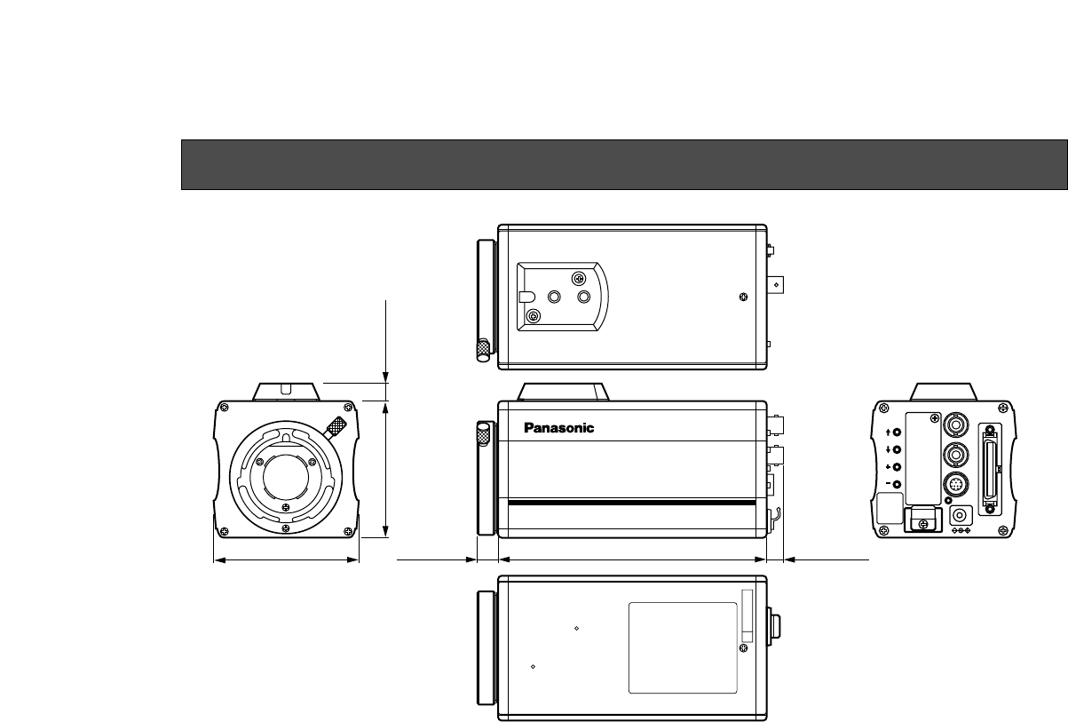
APPEARANCE ........................................................................................................................................................................ 49
SPECIFICATIONS ................................................................................................................................................................... 50
STANDARD ACCESSORIES ................................................................................................................................................... 52
OPTIONAL ACCESSORIES .................................................................................................................................................... 52

-2-
The Panasonic AW-E600 is a digital signal processing
color video camera that incorporates three 1/2” CCDs.
A digital video signal processing system is packed in a
compact, lightweight body while assuring high picture
quality, high reliability and high performance.
System setup and adjustments can be easily performed
1. Digital video signal processing for high quality, high
reliability, high performance, lightweight and com-
pact size.
2. Resolution: 850 lines (HIGH BAND DTL: ON), S/N
ratio: 65 dB (DNR ON)
3. Minimum illumination: 0.25 lux (F1.4, Night eye
HIGH mode)
4. SET UP menu for system check and readjustments.
5. Built-in automatic controls, including ATW, ELC,
and AGC
6. CCD readout is switchable between field and frame
modes. Vertical resolution can be stepped up in
frame mode and it is effective for shooting still
objects.
PREFACE
FEATURES
by following the setup menu.
Connection to peripheral devices, such as a RCU, a
RCB and a lens and the camera pan/tilt unit enables a
wide variation of system configurations.
Option cards may also be installed.
7. The built-in synchronized scanning system reduces
noise in computer graphics.
8. Various correction circuits permit video reproduc-
tion with high fidelity.
9. Chroma detail correction enables clear shots of
dark color objects.
10. A dark detail circuit provides natural edge correc-
tion to any object in a dark scene.

-3-
11. A digital highlight chroma circuit reproduces natural
dynamic ranges.
12. A digital color matrix enables high fidelity color
images.
13. Four use modes for each of your specific applica-
tions can be selected.
14. SMPTE color bar is indicated on the monitor screen.
15. Remote control with a RCU, RCB or a Hybrid con-
trol panel.
• Turn power off before connecting or disconnecting
cables.
• Connection or disconnection of any studio cable,
RCB cable or other cable to any unit of equipment
must be performed while power is off.
• While the camera is in automatic mode;
Shooting of bright objects in ELC operation mode
may result in a smeared picture unique to the CCD.
The ATW function under fluorescent illumination can
adversely change the white balance.
SPECIAL NOTES ON OPERATION

-4-
DONT'S
• Do not attempt to disassemble the camera, Remote
Control Unit (RCU) or other units. In order to pre-
vent electric shock, do not remove screws or cov-
ers. There are no user-serviceable parts inside.
• Do not abuse the camera. Avoid striking, shaking,
etc. The camera contains sensitive components
which could be damaged by improper handling or
storage.
• Do not let the lens remain uncapped when the cam-
era is not in use. If the lens is not installed, do not
leave the lens mount hole uncovered.
• Do not touch the surface of the lens or prism.
• Do not use strong of abrasive detergents when
cleaning the camera body.
• Do not aim the camera toward the sun, no matter
whether it is turned on or not.
• Do not expose the camera or Remote Control Unit
(RCU) to rain or moisture, and do not try to operate
the equipment in wet conditions. Do not operate the
camera or RCU if it becomes wet.
• Do not operate the camera or Remote Control Unit
(RCU) outdoors during a lightning storm.
• Do not use the camera in an extreme environment
where high temperatures or high humidity exist.
• Do not leave the camera and Remote Control Unit
(RCU) turned on when not in use. Do not unneces-
sarily turn the camera power on and off repeatedly.
Do not block the ventilation slots.
PRECAUTIONS

-5-
• Take immediate action if ever the camera or RCU
should become wet. Turn the power off and have
the unit checked by an authorized service facility.
• Follow normal safety precautions to avoid personal
injury.
• Use the camera in an environment where the tem-
perature is within −10°C - +45°C (14°F - 113°F),
and the relative humidity is within 30 % - 90 %.
• Always turn the power off when the camera is not
going to be used. Operate the camera and RCU
only when there is adequate ventilation.
DO'S
• Refer any servicing to qualified service personnel.
• Handle the camera with care.
• Protect the precision made lens by placing the lens
cap over when the camera is not in use. If the lens
is not installed, protect the surface of the prism by
placing the body cap into the lens mount hole.
• Use a mild blower or lens cleaning tissue designed
for coated lenses, to clean the surface of the lens or
prism in the event that it should become dirty.
• Use a dry cloth to clean the camera if it is dirty. In
case the dirt is hard to remove, use mild detergent
and wipe gently.
• Use caution when operating the camera in the
vicinity of spot lights or bright lights, as well as light
reflecting objects and surfaces.
Convertible Camera AW-
E600E600
-6-
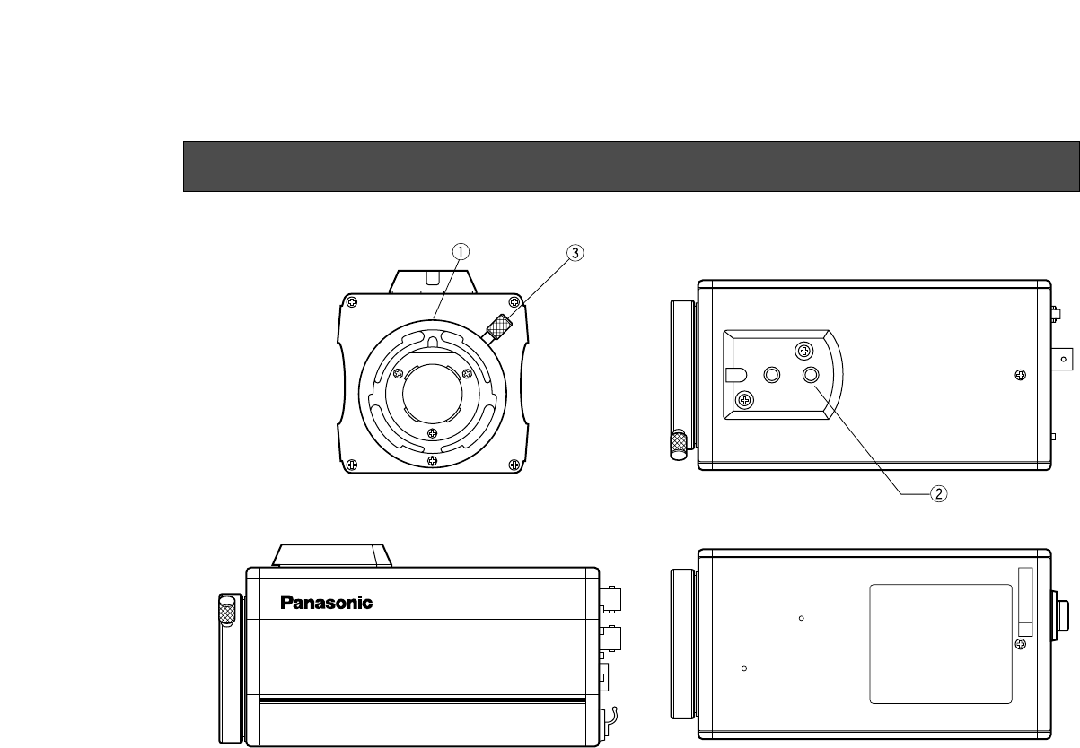
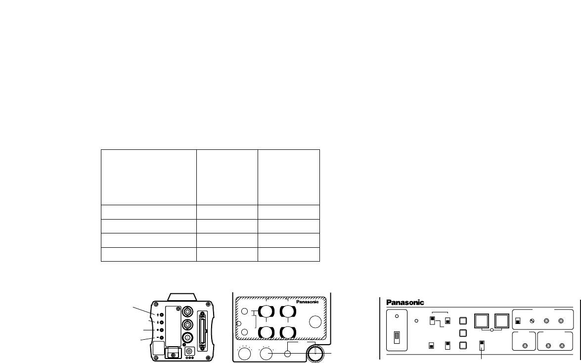
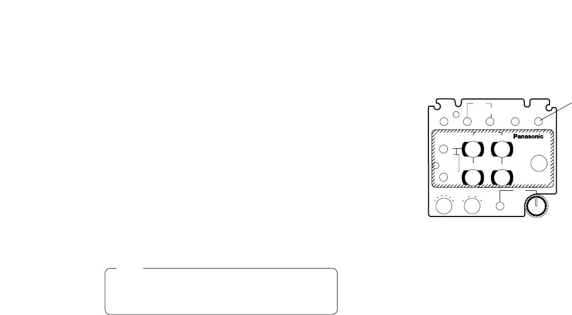
<Front View> <Top View>
<Bottom View><Side View>
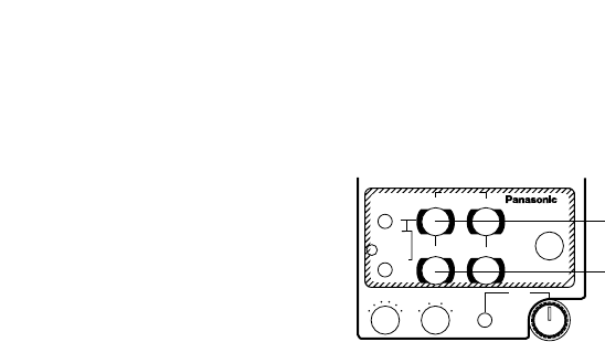
MAJOR OPERATING CONTROLS AND THEIR FUNCTIONS
-7-
3. Lens fixing ring knob
Rotate the lens fixing ring knob counterclockwise
and remove the lens mount cap. Mount the lens on
the camera and rotate the lens fixing ring knob
clockwise in order to fix the lens securely.
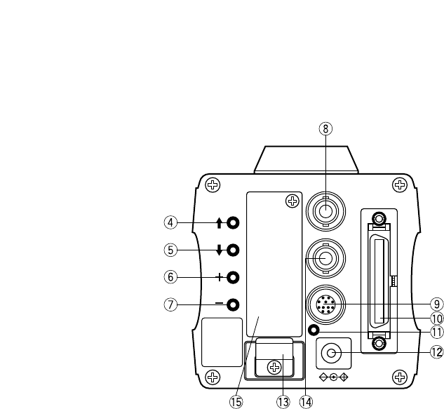
4. MENU Switch (MENU/M)
A menu will appear on the monitor screen when this
switch is pressed for about 5 seconds. This item
can be selected by pressing the switch while the
menu is on the screen.
5. ITEM/AWC Switch (ITEM/AWC/<)
The item just below can be selected by pressing
this switch while the menu is on the screen. When
the menu is not displayed or the camera is in shoot-
ing mode, the automatic white balance control can
be set with this switch.
6. YES/ABC Switch (YES/ABC/+)
The Sub Menu for each item of the Main Menu is
displayed when this switch is pressed while the
Main Menu is on the screen.
While the Sub Menu is displayed, any setting can
be brought up to a higher value with this switch.
When the menu is not displayed or the camera is in
shooting mode, the automatic black balance control
can be set with this switch.
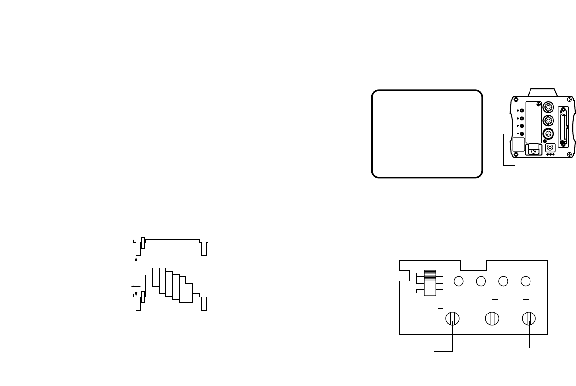
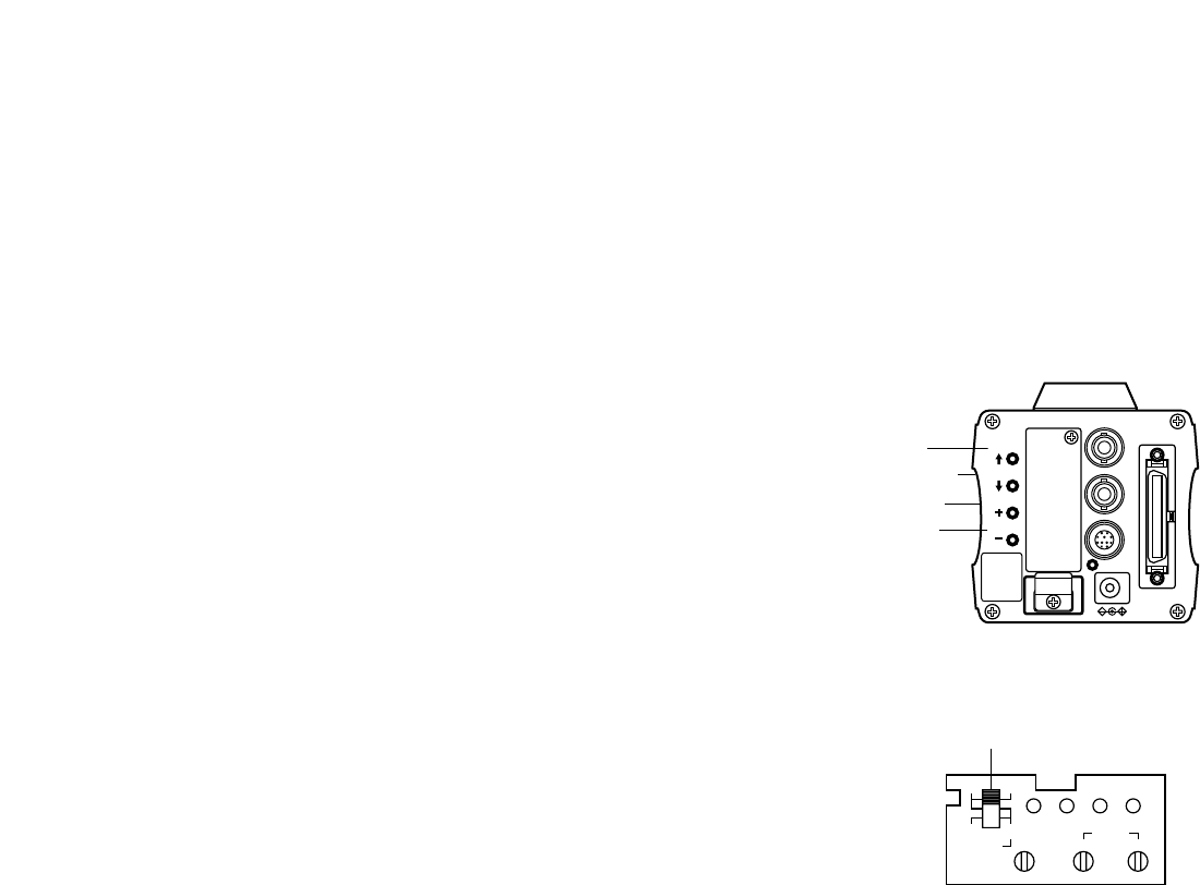
VIDEO OUT
G/L IN
I/F REMOTE
OPTION CARD
IRIS
DC12V IN
MENU
ITEM/AWC
YES/ABC
NO/BAR
CAUTION
CONNECT TO
SPECIFIED
CLASS 2 POWER
SUPPLY ONLY.
SEE MANUAL.
1. Lens Mount
1/2" Standard bayonet type lens or a microscope
adaptor can be mounted.
2. Mounting Adaptor
A screw hole (1/4” - 20 UNC) adaptor for mounting
the camera on a wall, ceiling with a mounting
bracket or tripod.
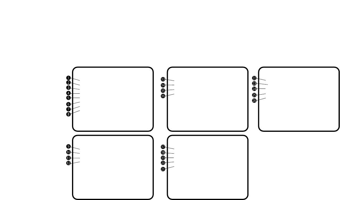
-8-
Pin No. Signal Pin No. Signal
1 Return Control 7 Iris Follow
2 Not Used 8 Auto/Remote Control
3 GND 9 Not Used
4 Auto/Manual Control 10 Not Used
5 Iris Control 11 Not Used
6 Lens Power 12 Not Used
<Front View>
Iris Connector (IRIS)
oq
iw
ue
ytr
!2
!0
!1
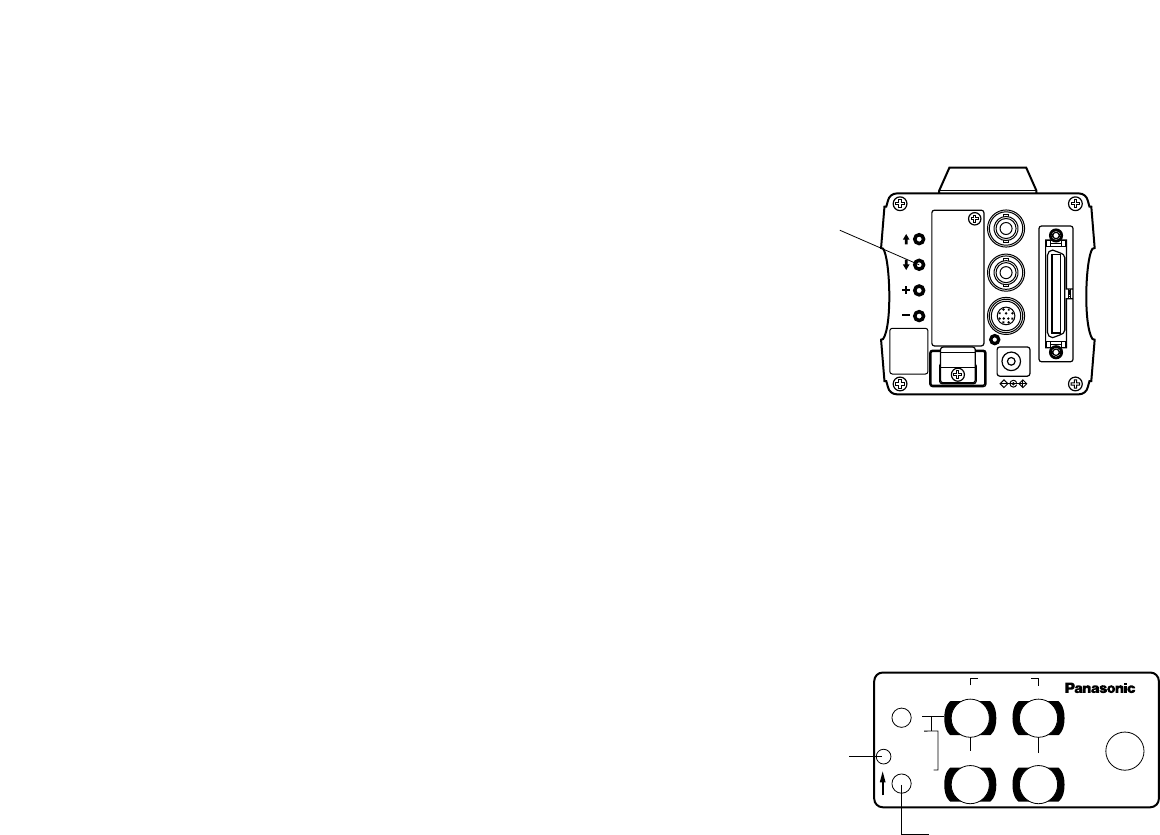
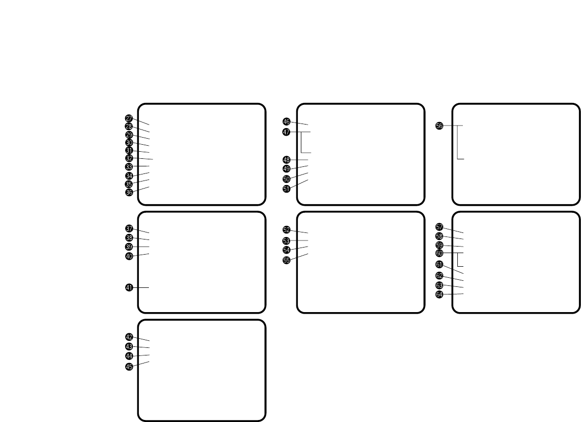
10. I/F Remote Connector (I/F REMOTE)
Input terminal dedicated to control signals from the
optional Remote Control Box (RCB) (WV-CB700A)
and the RCU (WV-RC700A, WV-RC550) and the
camera pan/tilt unit (AW-PH300).
* WV-CB700A is connected through the optional RCB
cable (AW-CA50T10).
* WV-RC700A/WV-RC550 is connected through the
optional RCU cable (AW-CA50A26).
* AW-PH300 is connected through the optional pan/
tilt unit cable (AW-CA50T15).
11. Power Indicator
Red LED lamp lights to indicate that the specified
DC power is supplied to the camera.
7. NO/BAR Switch (NO/BAR/−)
The item just below can be selected by pressing
this switch while the Sub Menu is on the screen.
While the Sub Menu is displayed any setting can be
brought down to a lower value with this switch.
When the menu is not displayed or the camera is in
shooting mode, the color bar and the shooting con-
ditions are alternately indicated by pressing the
switch.
8. Video Output Connector (VIDEO OUT)
A composite video signal is provided at this con-
nector.
9. Iris Connector (IRIS)
Input terminal for lens with an iris control function.

-9-
13. Cable Clamp
Clamp the DC Power Supply Cable (AW-CA4T1)
connected to the DC 12 V Input Connector to pre-
vent it from slipping out.
14. G/L Input Connector (G/L IN)
Signals synchronized with the reference signal are
to be supplied to this connector when the camera is
to be synchronized with the reference signal BB.
15. Optional Card Slot
Slot for inserting an optional card. For details, refer
to the manual for optional cards.
12. DC 12 V Input Connector (DC 12V IN)
12 V DC is supplied through the optional DC power
supply cable (AW-CA4T1).
-10-
• Lenses of any make can be mounted on the cam-
era as long as they are equipped with a 1/2” stan-
dard bayonet.
• Use the lens extension cable WV-CA12T12 (6”/
15 cm) if your lens cable is too short.
VIDEO OUT
G/L IN
I/F REMOTE
OPTION CARD
IRIS
DC12V IN
MENU
ITEM/AWC
YES/ABC
NO/BAR
Control Cable To Lens I/F Connector of
Camera Pan/tilt Unit
Camera Cable
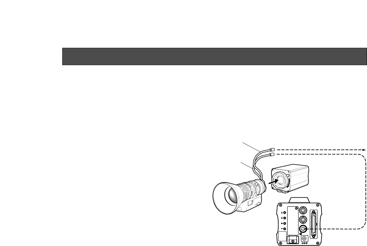
1. Lens Mounting
Rotate the lens fixing ring knob counterclockwise
and remove the lens mount cap. Mount the lens on
the camera and rotate the lens fixing ring knob
clockwise in order to fix the lens securely. Connect
the camera cable to the IRIS connector on the back
panel of the camera.
MOUNTING
-11-
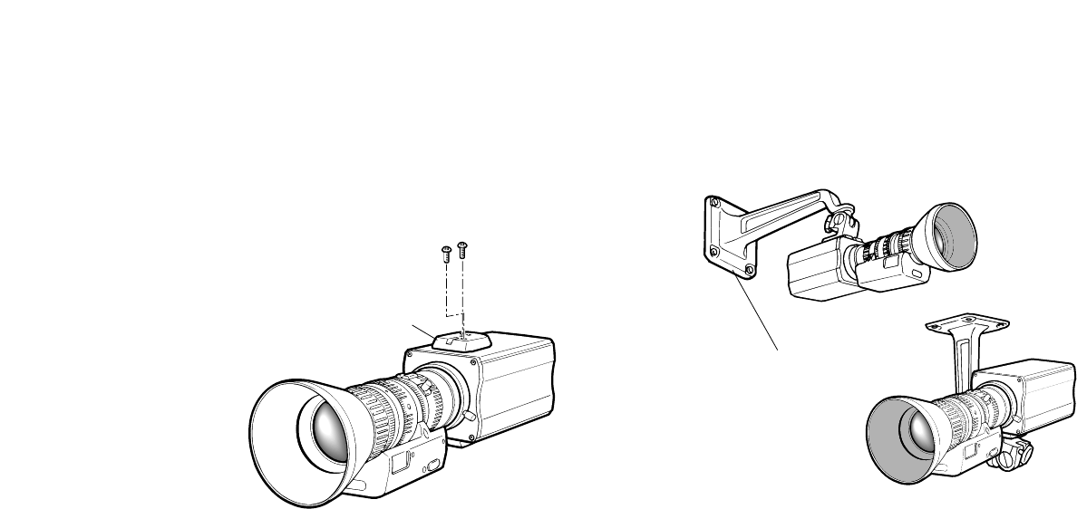
2. Fix the camera mounting base, pan/tilt unit, and tri-
pod securely in the screw hole (1/4-20UNC) of the
camera mounting adaptor.
3. If the camera cannot be securely fixed, stick the
supplied rubber sheet to the mounting adaptor,
then mount the camera.
Mounting adaptor
2. Camera Mounting
1. Fix the mounting adaptor to the top or bottom of the
camera.
Camera Mounting Bracket (WV-831)
-12-
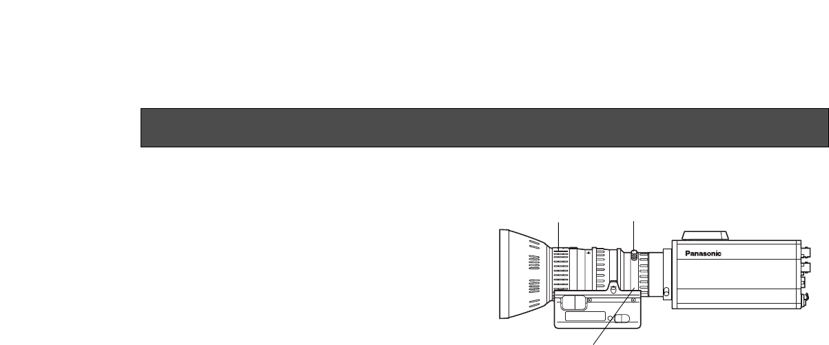
1. Fully open the iris by shooting a dark object. (Iris
selection switch should be set to M.)
2. Loosen the flange back lock knob.
3. Aim the camera at any object over 2 meters away
from the camera.
4. Set the lens to its TELE end first and adjust its focus
with the focus ring.
5. Set the lens to its widest angle next and adjust its
focus with the flange back adjust ring.
6. Adjust the focus ring and the flange back adjust
ring alternately for the best focus within the zoom-
ing range.
Tighten the flange back lock knob upon completion
of focusing.
7. Turn the iris selection switch to Position A.
Convertible Camera AW –
E600E600
Flange back lock knob
FOCUS Ring
Flange back adjust ring
FLANGE BACK ADJUSTMENT (FOR ZOOM LENS)
-13-
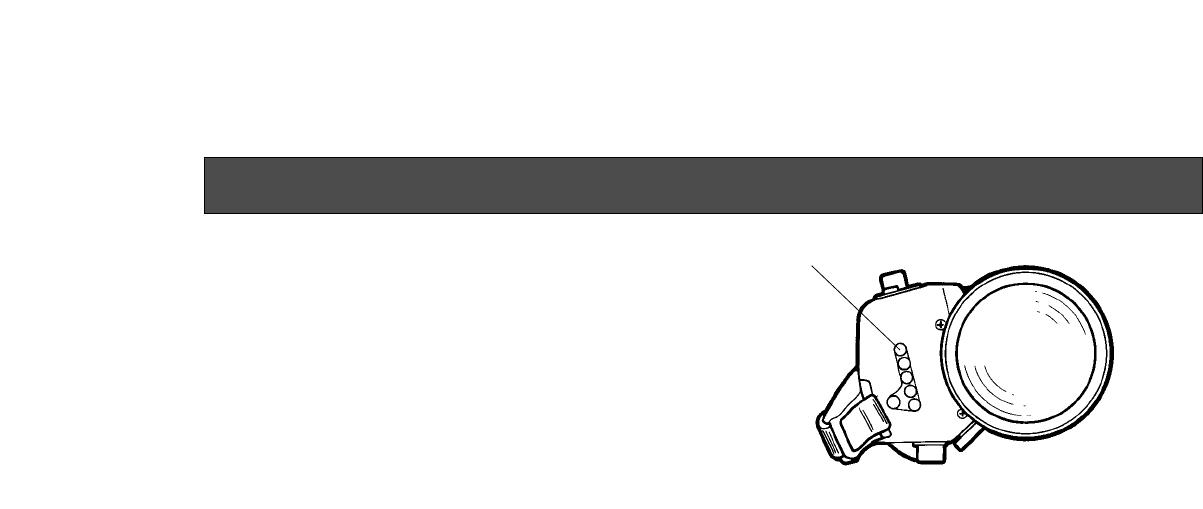
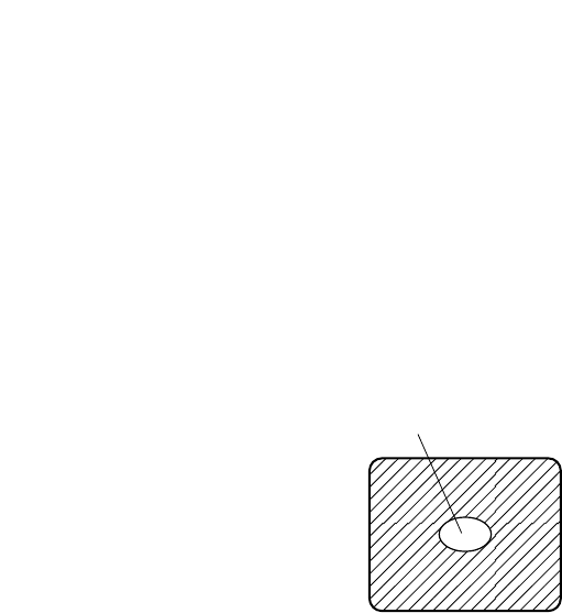
IRIS GAIN CONTROL IN A LENS
An iris gain control hole is usually provided in the front
of the lens. Adjustment of the iris gain, with a screwdriv-
er through the hole may be done as follows. (Shape
and location of the hole may vary depending on the
type of lens.)
1. Turn the iris selection switch to Position A (AUTO).
2. Rotate the iris gain control to the maximum gain,
but in a range where no hunting or oscillating of the
iris ring develops.
Iris gain control (G, S)
Automatic iris power zoom lens
-14-
Caution:
The connection and installation should be done by qualified service personnel or system installers.
Refer any servicing to qualified service personnel.
CONNECTIONS
VIDEO OUT
G/L IN
I/F REMOTE
OPTION CARD
IRIS
DC12V IN
MENU
ITEM/AWC
YES/ABC
NO/BAR
ON
POWER
OFF
POWER
O I
FUSE(POWER)
125V 3.15A
FUSE
FUSE
AC Adaptor
AW-
PS505
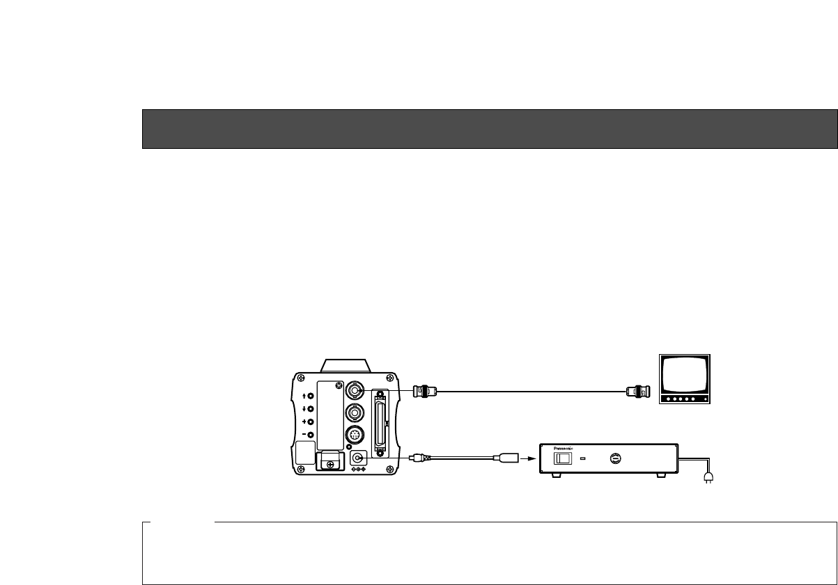
■CONNECTION OF DEVICE WITH A COMPOSITE INPUT CONNECTOR
1. Connect this to a DC 12 V class 2 power supply only.
2. To prevent fire or shock, the UL listed wire VW-1, style 1007 should be used as for the cable for DC 12 V Input
Connector.
Cautions
• Connection to any device which has a composite input connector, such as a video monitor or a VCR, must be made
through the VIDEO OUT Connector.
• Power supply to the camera must be through the optional DC power supply Cable AW-CA4T1.
• For DC power supply, use the optional AC adaptor AW-PS505.
VIDEO OUT
Connector Video monitor
AC Adaptor AW-PS505
VIDEO IN
75 Ωcoaxial cable
DC Power supply
Cable AW-CA4T1
-15-
GEN-LOCKGEN-LOCK
IN AUXAUX
IN
AUTOAUTO
75
/Hi-Z/Hi-Z AUTOAUTO
75
/Hi-Z/Hi-Z
R/PR /CR/PR /C
OUTOUT OUTOUT
AUDIOAUDIO
SEE MANUALSEE MANUAL
VIDEO 1VIDEO 1
G/Y/YG/Y/Y VIDEO 2VIDEO 2
B/PB /BB/PB /B SYNCSYNC
S-VIDEOS-VIDEO
1 4
2 3
TALLYTALLY
CAMERA (MULTI)CAMERA (MULTI)
CABLE SELECTCABLE SELECT FUSEFUSE
250V 1.25A250V 1.25A
TALKTALK
INCOMINCOM
RECEIVERECEIVE
CONTROLCONTROL
TALLY & INCOMTALLY & INCOM
MULTI OVPOVP
MPXMPX
MPXMPX
OUTPUTOUTPUT
VIDEO OUT
G/L IN
I/F REMOTE
OPTION CARD
IRIS
DC12V IN
MENU
ITEM/AWC
YES/ABC
NO/BAR
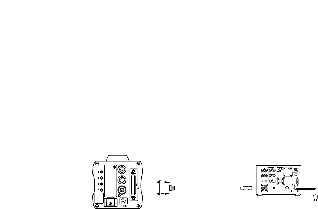
Connection to the RCU (WV-RC700A,WV-RC550) is
made through the optional RCU cable AW-CA50A26.
1. Turn RCU power off before connecting cables.
2. Set the cable selection switch of the RCU to MULTI
(in case of using the WV-RC700A)
3. Connect the 50-pin connector of the RCU cable to
the I/F REMOTE Connector of the camera.
4. Turn RCU power on and the power indicator lamp
will light. The camera can now be remote con-
trolled by the RCU.
Notes:
• The maximum extension distance between the
camera and WV-RC700A is 300 m. The maximum
extension distance between the camera and WV-
RC500 is 100 m.
• Use the following options for cable extension.
Studio Cable WV-CA26U15 (15 m/50 ft)
WV-CA26U30 (30 m/100 ft)
WV-CA26U100 (100 m/330 ft)
Cable Joint Adaptor
WV-CA26T26
■CONNECTION OF A REMOTE CONTROL UNIT (RCU)
Set to MULTI
WV-RC700A
RCU Cable
AW-CA50A26 (15 m)
-16-
VIDEO OUT
G/L IN
I/F REMOTE
OPTION CARD
IRIS
DC12V IN
MENU
ITEM/AWC
YES/ABC
NO/BAR
ALL 1
2
USER SET
ON
POWER
OFF
POWER
O I
FUSE(POWER)
FUSE
FUSE
AC Adaptor
AW-
PS505
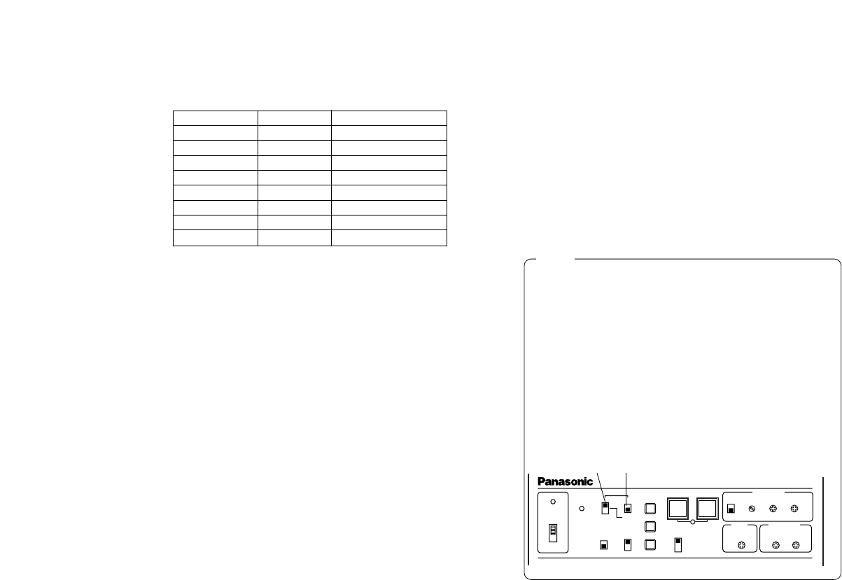
■CONNECTION OF A REMOTE CONTROL BOX (RCB)
The RCB (WV-CB700A) and the camera must be con-
nected with the optional RCB cable AW-CA50T10.
1. Turn RCB power off before connecting cables.
2. Connect the 50-pin connector of the RCB cable to
I/F REMOTE connector of the camera. The 10-pin
connector must be connected to the RCB.
3. Turn RCB power on and the camera can be con-
trolled remotely by the RCB.
Notes:
• The monitor output signals of the RCB attenuate
and deteriorate with cable length. It is recommend-
ed that the signals from the monitor output be used
for monitoring purposes only.
• No gen-lock signal is available from the RCB.
AC Adaptor
AW-PS505
Video signal IN
RCB WV-CB700A
1. Connect this to a DC 12 V class 2 power supply
only.
2. To prevent fire or shock, the UL listed wire VW-1,
style 1007 should be used as for the cable for DC
12 V Input Connector.
Cautions
RCB Cable AW-CA50T10 (3 m)
MONITOR OUT
DC Power Cable
AW-CA4T1
RCB
-17-
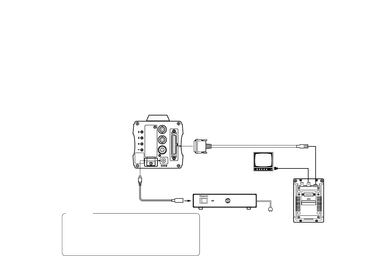
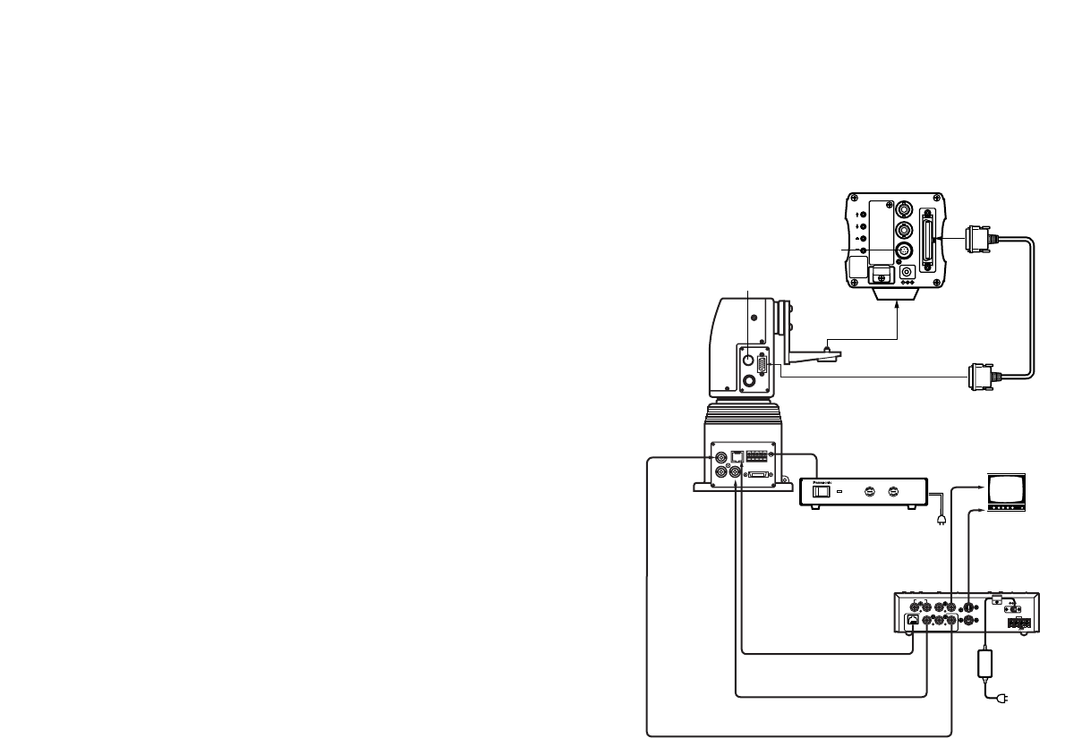
• To connect the pan/tilt unit to the camera, use the
pan/tilt unit cable AW-CA50T15.
• Power is supplied from the pan/tilt unit.
1. Before connecting them, press the power
switch on the pan/tilt unit AC adaptor and the
ON/OFF switch on the hybrid control panel in
the OFF position, respectively.
2. Fix the camera securely to the pan/tilt unit using
the mounting adaptor.
3. Connect the 50-pin end of the pan/tilt unit cable
to the I/F Remote connector on the camera.
Connect the 15-pin end of the cable to the
pan/tilt unit.
4. Connect the pan/tilt unit to the hybrid control
panel with the 10BASE-T cable and coaxial
cable. For details, refer to the manual for the
hybrid control panel.
5. First switch on the pan/tilt unit AC adaptor, then
press the ON/OFF switch on the hybrid control
panel in the ON position. The camera and pan/
tilt unit can now be controlled from the hybrid
control panel.
■CONNECTION OF DEVICES WITH CAMERA PAN/TILT CONTROL SYSTEM
TALLY
DC12V IN
AUX CONTROL
PREVIEW INOUT 6/1 OUT
BREVIEW MONITOR OUT
CONTROL CONTROL OUT
PAN/TILT CAMERA
TD MULTI PORT HUB
G / L IN
S-VIDEO OUT
ON
POWER
OFF
POWER
O I
FUSE(POWER)
FUSE
FUSE
FUSE(LAMP)
FUSE
FUSE
AC Adaptor
AW-PS300
VIDEO OUT
G/L IN
I/F REMOTE
OPTION CARD
IRIS
DC12V IN
MENU
ITEM/AWC
YES/ABC
NO/BAR
PAN/TILT CONTROL
CAMERA CONTROL
10BASE-T
Cable
Coaxial
Cable
Coaxial
Cable VIDEO
Control Panel
AC Adaptor
AW-PS301
Pan/tilt unit AC
Adaptor AW-PS300
Hybrid control
panel
AW-RP501
Camera Mounting
Hole Adaptor
(Supplied)
Pan/tilt unit Cable
AW-CA50T15
Composite Video S VIDEO
Video
Monitor
LENS
ZOOM/FOCUS Cable
LENS
IRIS Cable
Pan/tilt unit
AW-PH300
-18-
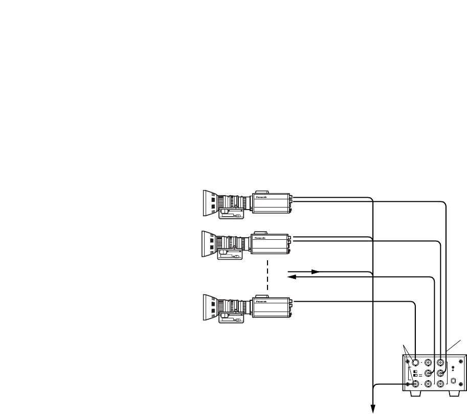
■CONNECTION WITH MULTIPLE CAMERAS (COLOR LOCK MODE)
●An example of connection for VBS/BB input (Color lock
mode).
• One of the multiple cameras is used as the source of ref-
erence signals.
• Supply a synchronizing signal (BB) to the G/L Input
Connectors of each cameras.
• Do not switch off the camera used for supplying the
reference signals.
• Adjust the SC-phase and H-phase at the Video
Output Connector.
1
2
3
1
2
3
OUTPUT BOUTPUT A
INPUT
THR SEP
75ΩHI-Z
B
A
Convertible Camera AW –
E600
Convertible Camera AW –
E600
Convertible Camera AW –
E600
VIDEO OUT
CAMERA
Camera for External Sync
(or Special Effect Generator)
G/L IN
VIDEO OUT
OUTPUT
INPUT
Video Output
To Special Effect Generator or Monitoring System
Video
Distributor
WJ-300C
External Sync
Signal (BB)
-19-
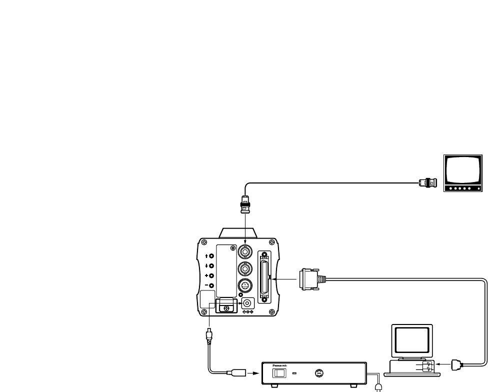
■CONNECTION OF COMPUTER
The system shown here can remotely control this camera by using a computer.
The software and the cable for RS-232C required for this operation should be obtained locally.
Please contact qualified service personnel for this software.
VIDEO OUT
G/L IN
I/F REMOTE
OPTION CARD
IRIS
DC12V IN
MENU
ITEM/AWC
YES/ABC
NO/BAR
ON
POWER
OFF
POWER
O I
FUSE(POWER)
FUSE
FUSE
AC Adaptor
AW-
PS505
DC Power Cable
AW-CA4T1
Computer
VIDEO OUT Connector
AC ADAPTOR AW-PS505
75 ΩCoaxial Cable
Composite Video
Input Connector
(VIDEO IN)
Video Monitor
RS-232C
PC Control Cable AW-CA50T9 (10m)
-20-
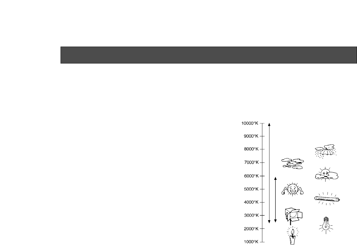
Color temperature and adjustment of white balance
When carbon is burnt, it develops various colors of light
depending on the temperature. Natural light can be
specified by color temperature referring to the color
developed when carbon is burnt.
The light of 3 200K (K=Kelvin, −273C equals to abso-
lute zero temperature 0K) represents the same value
(color) as what develops when carbon is burnt at
3 200K (2 927C). The relationship between the color
temperature of the light source and weather condition is
indicated in the right figure. Let’s study the difference
of shooting an indoor object from shooting one out-
doors. Studios are usually lighted with incandescent
lamps and the color temperature of a white object in a
studio is around 3 000K. The color temperature of a
white object outdoors is around 6 500 K. The former
may look a little yellowish while the latter appears
somewhat bluish when they are shot by a camera.
However, the human eye does not recognize color dif-
ferences among these objects even under different
ambient lighting conditions, because of their adaptabili-
ty to light. The video camera reproduces color differ-
ences with high fidelity and the color of an object some-
what different from what appears to the human eye.
Blue sky
Cloudy
AWC
Rainy
Partly cloudy
Fluorescent lamp
Fine
Halogen lamp
Tungsten lamp
Candle
ATW
Therefore, there is a need to adjust the white balance in
order to correct differences between color tempera-
tures.
NOTE: Color temperature outdoors may vary depend-
ing on weather conditions.
ADJUSTMENT
-21-
■AUTOMATIC WHITE BALANCE
CONTROL (AWC)
There are two white balance memories, “AWC A” or
“AWC B” for two different light sources color tempera-
tures, with the automatic white balance setting. Then,
when the two different light sources are encountered,
you may operate the camera properly by simply
change the white balance mode to either AWC A or
AWC B. There is no need to readjust the camera to the
ambient conditions.
* The preset conditions will be renewed whenever
you input new conditions.
1. Turn the white balance selection switch to either
“AWC A” or “AWC B” of RCU or select the white
balance mode either AWC A or AWC B by menu.
2. Aim the camera at a white object (a white wall or a
white handkerchief) and zoom in to enlarge the
image as much as possible.
[ADJUSTMENT by CAMERA]
3. In normal shooting mode:
Press the Item/AWC switch for over 2 second.
[ADJUSTMENT with the RCU (RCB, Hybrid control
panel)]
4. When the AUTO set switch is turned to AWC, the
white balance will be automatically set. While the
system is being set, auto warning indicator (LED)
blinks and it goes out when the white balance set-
ting is completed. If the lamp remains lit, the set-
ting must be tried again.
AUTO LED
R B
R B
PED
TOTAL
PED
A
B
ATW
AWC
AUTO
HOLD
ABC
AUTO/ATW PAINTING
GAIN
AUTO set switch
VIDEO OUT
G/L IN
I/F REMOTE
OPTION CARD
IRIS
DC12V IN
MENU
ITEM/AWC
YES/ABC
NO/BAR
ITEM/AWC
Switch
RCU (RCB)
CAMERA
-22-
Notes:
• For white balance setting aim the camera at a
white object and try to position it in the center of
the monitor screen. The object must appear in
over 10 % of the total monitor screen area. Try
to avoid overly bright objects in the scene.
• White balance may not be correctly set if the
lighting of the object is too weak.
• Since the camera has a built-in memory, the set
white balance will remain in the memory even if
power is turned off. Therefore, it is not neces-
sary to reset the white balance if the color tem-
perature of those objects remains unchanged.
However, it must be reset if the color tempera-
ture changes, such as when you move from
indoors to outside, or vice versa.
• When the camera is used without a RCU or
RCB red/blue gain adjustment of painting set-
ting will be automatically reset to ±0 after set-
ting the white balance. (painting setting in only
USER MODE.)
■AUTOMATIC TRACKING WHITE
BALANCE SETTING (ATW)
White balance will be automatically set to continuously
match changes of light source and color temperature
while the white balance setting is set to ATW.
Note: White balance may not be accurately set if there
is no white object in the scene being shot.
■MANUAL WHITE BALANCE SETTING
[ADJUSTMENT by CAMERA]
Manual setting is possible in USER MODE only.
1. Select the white balance mode either AWC A or
AWC B by menu.
2. Aim the camera at a large white object. Press the
Item/AWC switch for over 2 second.
3. Adjust the red gain/blue gain control in the PAINT-
ING item of Color Set sub menu of USER MODE
until the carrier wave of the white portion of the
video signal is at the minimum width or the white
object in the monitor screen appears pure white.
(Use an oscilloscope or a waveform monitor for pre-
cise adjustment.)
[ADJUSTMENT with the RCU (RCB)]
After AWC setting, adjust the R/B GAIN controller in the
same way as described in Step 3 above.
The white object must occupy over
10 % of the monitor screen area.
-23-
■RESET TO 3 200K OR 5 600K WHITE
BALANCE
When the white balance setting is set to either “P SET
3 200K” or “P SET 5 600K” the white balance will be
automatically set to the color temperature 3 200K or
5 600K, respectively.
■BLACK BALANCE ADJUSTMENT
• Close the lens.
If the motor drive lens is controlled from the cam-
era, the lens is automatically closed when the black
balance is adjusted.
• When the camera is used without a RCU or RCB,
R/B pedestal adjustment of painting setting will be
automatically reset to ±0 after setting the black bal-
ance. (painting setting in only USER MODE.)
[ADJUSTMENT by CAMERA]
Press the YES/ABC Switch for over 2 seconds and the
black balance will be set automatically in 10 seconds.
Minimize the carrier wave using
the red & blue gain controls
Waveform for white
balance set chart
R B
R B
PED
TOTAL
PED
A
B
ATW
AWC
AUTO
HOLD
ABC
AUTO/ATW PAINTING
GAIN
AUTO LED
ABC
YES/ABC Switch
AUTO
set switch
VIDEO OUT
G/L IN
I/F REMOTE
OPTION CARD
IRIS
DC12V IN
MENU
ITEM/AWC
YES/ABC
NO/BAR
In user mode, black balance fine adjustment can be
performed with the red pedestal/blue pedestal setting
after setting the black balance.
[ADJUSTMENT with the RCU (RCB, Hybrid control
panel)]
Set the AUTO set switch to ABC and the black balance
will be automatically set. While the system is being set,
the auto warning indicator (LED) blinks and it goes out
when the black balance setting is completed. If the
lamp remains lit, ABC should be tried again.
-24-
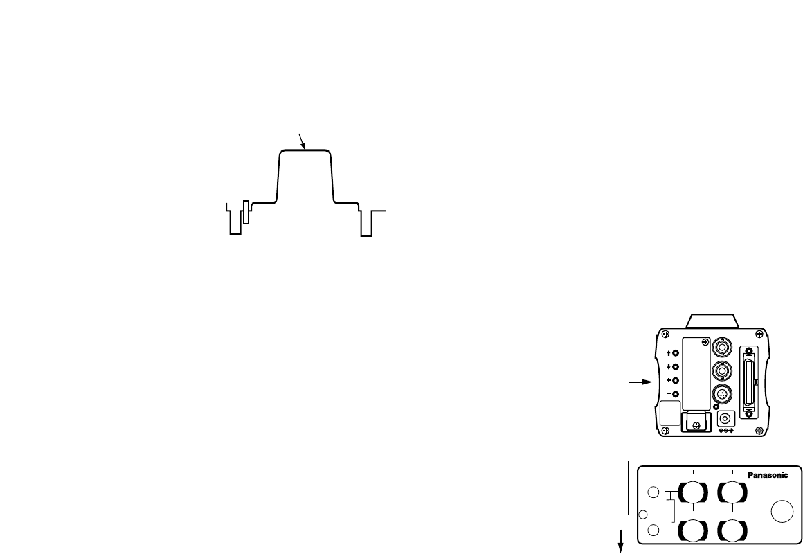
■TOTAL PEDESTAL LEVEL ADJUST-
MENT
(Use an oscilloscope or a waveform monitor for this
adjustment.)
This step is to adjust the black levels (pedestal levels)
of two or more cameras to be the same.
[ADJUSTMENT by CAMERA]
1. Close the lens.
2. Select Pedestal item in the brightness setting Sub
Menu (Select [Pedestal] in the [Iris, Shutter, Gain
Set] sub menu in USER MODE.)
3. Set the pedestal level to 5 IRE (0.035 V) with the
YES/ABC switch or the NO/BAR switch.
[ADJUSTMENT with RCU (RCB, Hybrid control panel)]
Adjust the pedestal level to 5 IRE with the total pedestal
adjustment.
**Brightness Set**
Picture Level ±0
Light PEAK/AVG 0
Light Area Top cut
Auto ND
(
ELC) OFF
Auto Gain Up OFF
Manu Gain Up 0dB
Pedestal ±0
Contrast(Gamma) MID
Return
VIDEO OUT
G/L IN
I/F REMOTE
OPTION CARD
IRIS
DC12V IN
MENU
ITEM/AWC
YES/ABC
NO/BAR
NO/BAR switch
YES/ABC switch
5 IRE
(0.035 V)
R B
R B
PED
TOTAL
PED
A
B
ATW
AWC
AUTO
HOLD
ABC
AUTO/ATW PAINTING
GAIN
TOTAL PEDESTAL
-25-
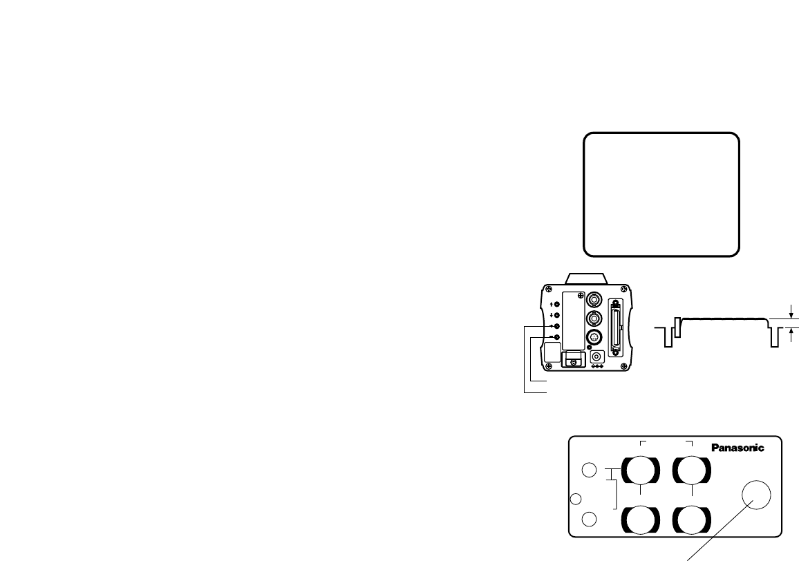
[ADJUSTMENT by CAMERA]
1. Press the NO/BAR switch for over 5 seconds to dis-
play the color bar.
2. Select [G/L. Color Bar Set] on the main menu, then
select [H PHASE] on the submenu.
3. Adjust the horizontal phase with the YES/ABC and
NO/BAR switch.
External gen-lock input signal
(black burst output of special
effect generator)
Video signal
[ADJUSTMENT with RCU (RCB, Hybrid control panel )]
Use the horizontal phase control.
**G/L.
@
Color Bar Set**
H Phase ±0
SC Coarse 1
SC Fine ±0
Color Bar Set 7.5IRE
Return
■GEN-LOCK ADJUSTMENT
Phase adjustments must be performed with the camera
or the RCU (RCB) when external synchronizing signals
are supplied to the system in cases where multiple
cameras are used or peripheral devices are connected.
●HORIZONTAL PHASE CONTROL
Observe the waveform of the external synchronizing
input signal (black burst signal) and video output signal
on a two-channel oscilloscope. Then match the hori-
zontal phase of both signals by adjusting them with the
cameras or RCU's horizontal phase control.
PAGE ITEM UP DOWN
COARSE FINE
SC PHASE
270°
180°90°
0°
H.PHASE
USER SET
OFFENC
VF ON
Horizontal phase
control
Subcarrier phase
coarse control
Subcarrier phase
fine control
Adjust the horizontal phase
VIDEO OUT
G/L IN
I/F REMOTE
OPTION CARD
IRIS
DC12V IN
MENU
ITEM/AWC
YES/ABC
NO/BAR
NO/BAR switch
YES/ABC switch
-26-
●COLOR PHASE ADJUSTMENT
Supply the output signal (split color bar) from the color
special effect generator to a color monitor or vec-
torscope. Adjust the color phase of the camera.
[ADJUSTMENT with RCU (RCB, Hybrid control panel)]
Use the subcarrier phase coarse adjustment control
and subcarrier phase fine control.
* It is recommended that a vectorscope be used for
maximum accuracy in color phase adjustment.
[ADJUSTMENT by CAMERA]
1. Press the NO/BAR switch for over 5 seconds for the
color bar mode.
2. Select [G/L. Color Bar Set] on the main menu, then
select [SC Coarse] on the sub menu.
3. Make coarse adjustment with the YES/ABC switch
and the NO/BAR switch.
4. Select [SC Fine] on the sub menu. Perform fine
adjustment with the YES/ABC switch and the
NO/BAR switch.
Magenta
Green
Cyan
Yellow
White
Red
Blue
Black
Magenta
Green
Cyan
Yellow
White
Red
Blue
Color bar of
camera
Color bar of special
effects generator
**G/L.
@
Color Bar Set**
H Phase ±0
SC Coarse 1
SC Fine ±0
Color Bar Set 7.5IRE
Return
Sprit line

-27-
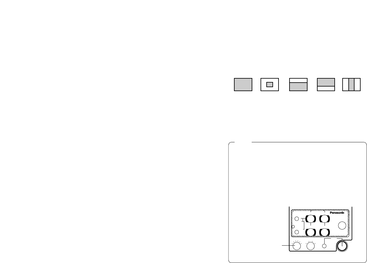
■Use Mode Setting
The camera has four use modes, and various functions
for four use modes have been preset.
Functions can be set as best suited to each use mode.
• Halogen mode
Suited to indoor shooting, such as at weddings,
parties, lecture meetings, events, etc.
Settings can be changed using a simple menu.
• Fluorescent mode
Suited to indoor shooting under fluorescent lighting.
Settings can be changed using a simple menu.
• Outdoor mode
Suited to outdoor shooting.
Settings can be changed using a simple menu.
• User mode
Settings can be changed using a detail menu.
■SETTING BY CAMERA
1. Turn the camera on while keeping the MENU switch
depressed.
The use mode setting menu shown at right appears
on the monitor screen and one of the use mode
blinks.
2. Press the MENU switch, ITEM/AWC switch, or
NO/BAR switch to let the desired use mode blink.
MENU switch (M): The blinking item moves up by
one.
ITEM/AWC switch (<), NO/BAR switch (–): The
blinking item moves down by one.
3. Press the YES/ABC switch.
The blinking use mode comes into effect. After the
use mode setting menu is shown for about 5 sec-
onds, the camera returns to be ready for operation.
Then, the camera operates in the selected use
mode.
USE MODE SETTING
**Use Mode Set**
Halogen
Fluorescent
Outdoor
User
POWER
OPERATE
BAR
CAM
MODE
GAIN AWC
SCENE
FILE
ABC
ATW
A
B
AUTO/AIW
ELC
LOW
MID
MANU
ON SC H
OFF
HIGH AGC
OFF
1 / 100
SHUTTER
ON
OFF
1 .
2 .
3 .
4 .
G/L PHASE
T.PED CABLE COMP
90° 180°
0° 270°
YC
SCENE FILE Switch
Operation mode
-28-
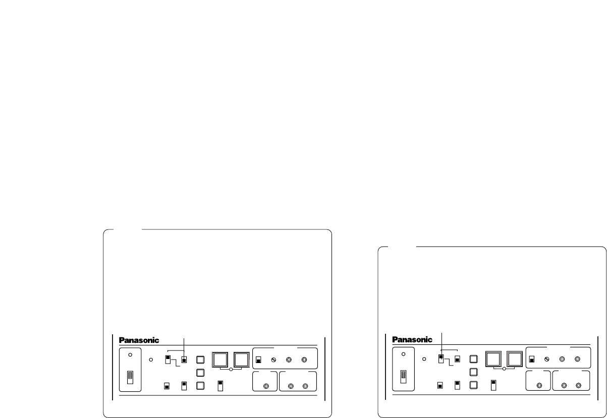
■SETTING BY RCU (RCB) OR HYBRID
CONTROL PANEL
An operation mode is selected depending on the posi-
tion of the scene file switch.
Halogen Mode
Fluorescent Mode
Outdoor Mode
User's Mode
Scene File
Switch
Position of
RCU (RCB)
1
2
3
USER SET
Scene File
Switch
Position of
Hybrid control
panel
1
2
3
4
VIDEO OUT
G/L IN
I/F REMOTE
OPTION CARD
IRIS
DC12V IN
MENU
ITEM/AWC
YES/ABC
NO/BAR
MENU
R B
R B
PED
TOTAL
PED
A
B
ATW
AWC
AUTO
HOLD
ABC
IRIS
MAN
AUTO
1000S/S
ELC
500
100
OFF
SHUTTER SCENE
21 3
USER
SET
AUTO/ATW PAINTING
GAIN
ITEM/AWC
YES/ABC
NO/BAR SCENE
FILE
Switch
CAMERA RCU (RCB) Hybrid Control Panel
-29-
■MENU ITEM SETTING
• Each of the four use modes of the camera has a
main menu. (Shown at right)
• Each item of the main menu has a submenu, which
consists of several settings.
• These settings have been preset to the optimum
values to suit each use mode, and can be changed
to suit actual shooting conditions.
• They can be set from the camera and RCU (RCB).
They can also be set from the hybrid control panel
using the switches, but the setting items are limited
because the menu is not shown.
Notes:
• Composite signals are output from the video
output regardless of the position ENC/VF of the
RCU (RCB) user set switch.
• [End] is displayed only in setting from the cam-
era alone.
●MAIN MENU SCREEN
MENU ITEM SETTING
**Halogen Mode Set**
Brightness Set
Color Set
G/L. Color Bar Set
Sharpness Set
Other Set
Initialize Data
End
Use Mode
Blinking
**User Mode Set**
Iris, Shutter, Gain Set
Color Set
G/L. Color Bar Set
Detail Set1 Detail Set2
Color Matrix Set
Other Set
Initialize Data
End
Main Menu of Halogen,
Fluorescent, Outdoor Mode
Main Menu of User Mode
-30-
■SETTING
1. From the camera alone:
Keep the MENU switch depressed for 5 sec-
onds or more.
From RCU (RCB):
Set the user set switch in the pocket to the ON
position.
The main menu appears on the monitor screen.
2. Each time the MENU switch (M), ITEM/AWC switch
(<), or NO/BAR switch (−) is pressed, the blinking
item moves up or down.
3. When the YES/ABC switch is pressed after select-
ing the desired item to blink, the submenu for the
selected item appears on the screen.
4. Select the desired item to be changed in its settings
using the the MENU switch (M) and ITEM/AWC
switch (<).
5. Press the YES/ABC switch (+) or NO/BAR switch (–)
to change the settings.
6. Select [Return] using the MENU switch and ITEM/
AWC switch, then press the YES/ABC switch to
return to the main menu.
7. After changing the settings, take the following
steps.
Camera alone: Select [End] using the MENU
switch and ITEM/AWC switch and press the
YES/ABC switch.
VIDEO OUT
G/L IN
I/F REMOTE
OPTION CARD
IRIS
DC12V IN
MENU
ITEM/AWC
YES/ABC
NO/BAR
MENU
ITEM/AWC
YES/ABC
NO/BAR
PAGE ITEM UP DOWN
COARSE FINE
SC PHASE
270°
180°90°
0°
H.PHASE
USER SET
OFFENC
VF ON
USER SET SWITCH
RCU (RCB): Set the user set switch in the pocket to
the OFF position.
The camera will now operate according to the new
settings.
CAMERA
RCU (RCB)
-31-
• Settings enclosed in parentheses can be set with the RCU (RCB) switch or VR in RCU (RCB) mode.
• To return to the initial settings, refer to page 46.
■SUB MENU (Halogen Mode, Fluorescent Mode, Outdoor Mode)
**Brightness Set**
Picture Level ±0
Light PEAK/AVG 0
Light Area Top cut
Auto ND (ELC) (OFF)
Auto Gain Up (OFF)
Manu Gain Up (0dB)
Pedestal (±0)
Contrast(Gamma) MID
Return
**G/L. Color Bar Set**
H Phase ±0
SC Coarse (1)
SC Fine (±0)
Color Bar Set (7.5IRE)
Return
**Other Set**
Shutter Speed (OFF)
Syncro Scan ---
V Resolution Normal
Baud Rate 9600bps
Nega/Posi Posi
Return
**Color Set**
Chroma Level ±0
Flesh Tone ±0
White Bal (AWC A)
Highlight Chroma OFF
Return
**Sharpness (DTL) Set**
DTL Select Sharpness
Level (HIGH)
Noise Suppress OFF
Clean DNR OFF
DTL Flesh Tone MID
Return
• ON is automatically selected when the electronic
shutter @2 on the submenu [Other Set] is set to
[Auto ND]. OFF is selected when other than [Auto
ND] is selected.
• ON is selected when the SHUTTER switch is set
to [ELC] in RCU (RCB) mode, and OFF is select-
ed when it is set to other than [ELC].
-32-
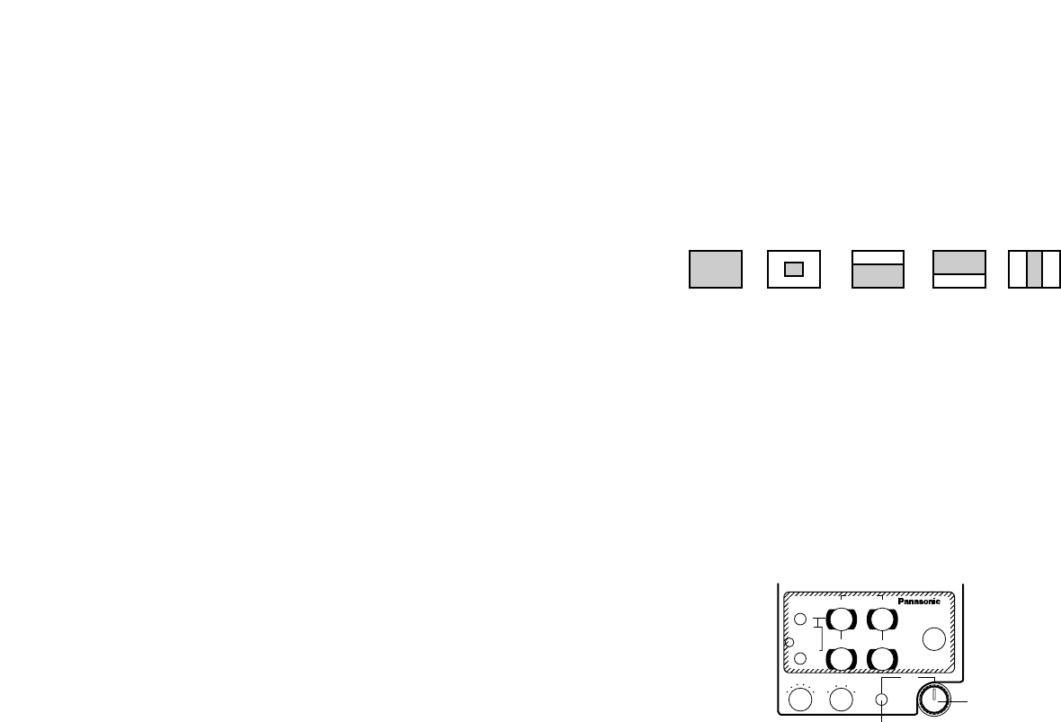
■Setting and Changing of the
Setting (Halogen Mode, Fluores-
cent Mode, Outdoor Mode)
qVideo Level Adjustment
[Picture Level: –50 - +50]
Convergence level of AUTO IRIS/AUTO GAIN UP/
AUTO ND (ELC) can be adjusted.
wDetecting Ratio Adjustment [Light PEAK/AVG:
P50 - A50]
The ratio of AUTO IRIS/AUTO GAIN UP/AUTO ND
(ELC) detected peak to average can be adjusted
within a predetermined range.
ePhotometric Measurement Method Setting [Light
Area: All, Center, Top cut, BTM cut, R/L cut
A photometric measurement method can be select-
ed for AUTO IRIS/AUTO GAIN UP/AUTO ND (ELC).
All: All the screen area is measured.
Center: The screen is measured mainly in the cen-
ter area, about one-third of both the top and bot-
tom and one-third of both the right and left por-
tions of the screen are excluded from measure-
ment.
Top cut: About one-third of the top part of the
screen is excluded from measurement.
BTM cut: About one-third of the bottom portion of
the screen is excluded from measurement.
rAuto ND (ELC) Setting [Auto ND (ELC): ON/OFF]
ON: The electronic shutter is controlled to automati-
cally adjust the luminance.
OFF: Luminance is not automatically adjusted by
the electronic shutter.
All Center Top cut BTM cut R/L cut
SHUTTER
RCU (RCB)
R/L cut: About one-third of both the right and left
portions of the screen are excluded from mea-
surement.
Notes
R B
R B
PED
TOTAL
PED
A
B
ATW
AWC
AUTO
HOLD
ABC
IRIS
MAN
AUTO
1000S/S
ELC
500
100
OFF
SHUTTER SCENE
21 3
USER
SET
AUTO/ATW PAINTING
GAIN
• In case of settings on the camera alone or when
the iris switch on the RCU (RCB) is at [AUTO], the
Auto Gain Up control may not operate if the lens
iris switch is in the manual position.
• When the AGC switch on the hybrid control panel
is set to AGC, the Auto Gain Up control operates
in the HIGH position.
POWER
OPERATE
BAR
CAM
MODE
GAIN AWC
SCENE
FILE
ABC
ATW
A
B
AUTO/AIW
ELC
LOW
MID
MANU
ON SC H
OFF
HIGH AGC
OFF
1 / 100
SHUTTER
ON
OFF
1 .
2 .
3 .
4 .
G/L PHASE
T.PED CABLE COMP
90° 180°
0° 270°
YC
-33-
tAuto Gain Up Control Setting [Auto Gain Up:
OFF/ LOW/HIGH]
LOW: The Auto Gain Up control with a maximum
gain increase of about 18 dB adjust the lumi-
nance automatically.
HIGH: The Auto Gain Up control with a maximum
gain increase of about 30 dB operates. If the
luminance is still insufficient, the Night Eye also
operates to adjust the luminance automatically.
OFF: No auto gain up takes place. (Gain can be
increased manually.)
Hybrid Control Panel
AGC
yManual Gain Up Control Setting [Manu Gain Up:
0 dB - 30 dB / N/Eye L / N/Eye H]
Manual setting is possible only when the Auto Gain
Up control is in the OFF position.
0 dB: 0 dB should be selected in normal cases.
1 dB - 30 dB: Use this range if sufficient video out-
put cannot be obtained even when the lens iris
is opened in shooting dark scenes.
N/Eye L / N/Eye H (Night Eye L/H): Use this mode
if sufficient video output cannot be obtained
even if 30 dB gain up should be selected.
Night Eye can be selected to any of two (L or H)
levels.
Hybrid Control Panel
Manual GAIN
Notes
• Only 0 dB, 9 dB, or 18 dB can be selected in
case of using the RCU (RCB).
• 0 dB when the manual GAIN switch on the hybrid
control panel is at LOW, 9 dB when it is at MID, or
18 dB when it is at HIGH.
POWER
OPERATE
BAR
CAM
MODE
GAIN AWC
SCENE
FILE
ABC
ATW
A
B
AUTO/AIW
ELC
LOW
MID
MANU
ON SC H
OFF
HIGH AGC
OFF
1 / 100
SHUTTER
ON
OFF
1 .
2 .
3 .
4 .
G/L PHASE
T.PED CABLE COMP
90° 180°
0° 270°
YC
Notes

-34-
uBlack Level Setting [Pedestal: –30 - +30]
The black level (pedestal) of the luminance (Y) sig-
nal can be set. Used in adjusting the black levels
of two or more cameras.
iContrast Adjustment [Contrast (Gamma):
LOW/MID/HIGH]
Contrast can be adjusted to any of three levels.
oChroma Level Adjustment
[Chroma Level: –3 - +3]
Chroma Level can be decreased or increased to
any of three levels each.
!0 Skin Color Adjustment [Flesh Tone: –3 - +3]
Skin color can be decreased or increased to any of
three levels each.
!1 White Balance Setting [White Bal: ATW/AWC A/
AWC B/P SET 3 200K/P SET 5 600K]
ATW: The white balance is automatically adjusted
to be always right.
AWC A, AWC B: Once the white balance is adjust-
ed with the ITEM/AWC switch on the back of the
camera, it is no longer necessary to set the
white balance again if you simply select AWC A
or AWC B, provided that the camera is used
under the same conditions.
Fine color adjustment can be made after setting
AWC by red/blue gain adjustment in user mode
or from the RCU (RCB).
P SET 3 200K: The white balance is adjusted to
3 200K illumination.
P SET 5 600K: The white balance is adjusted to
5 600K illumination.
!2 Highlight Chroma Setting [Highlight Chroma:
OFF/LOW/HIGH]
At LOW or HIGH, the color dynamic range widens
to prevent highlighted white portions from suppres-
sion.
!3 Horizontal Phase Adjustment
[H Phase: –206 - +49]
Horizontal phase can be adjusted when a genlock
signal is supplied.
!4 Sub Carrier Phase Coarse Adjustment
[SC Coarse: 1/2/3/4]
Coarse adjustment of subcarrier phase can be
made when a genlock signal is supplied.
Neither P SET 3 200K nor P SET 5 600K can be set
from the RCU (RCB) or the hybrid control panel.
Note
-35-
Neither Sharpness nor Super DTL is valid for con-
tour correction if Detail Level setting !8 is in the
OFF position.
!8 Detail Level Setting [Level: OFF/LOW/HIGH]
Detail level can be adjusted when Detail Select set-
ting !7 is at Sharpness. Super DTL level can be
adjusted when it is at Super DTL.
In case of using the RCU (RCB), the above can be
adjusted with the contour correction switch (DTL).
IRIS
MAN
AUTO
1000S/S
ELC
500
120
OFF
SHUTTER SCENE
21 3
USER
SET
OFF
ON +18
+9
0(dB)
+6
OFF
−6(dB)
GAIN
BAR
CAM
HIGH
LOW
OFF
RCB DTL
AGC
R B
R B
PED
TOTAL
PED
A
B
ATW
AWC
AUTO
HOLD
ABC
AUTO/ATW PAINTING
GAIN
RCU (RCB)
DTL
!5 Subcarrier Phase Fine Adjustment [SC Fine:
–511 - +511]
Fine adjustment of subcarrier phase can be made
when a genlock signal is supplied.
!6 Color Bar Setup Setting [Color Bar Set:
0.0IRE/7.5IRE]
The setup level of color bar can be adjusted.
!7 Detail Select Setting [DTL Select: Sharpness/
Super DTL]
If contour correction is not sufficient at the
Sharpness position when Detail Level setting !8 is
set to LOW or HIGH, select the Super DTL position. !9 Noise Suppress Level Setting [Noise Suppress:
OFF/LOW/HIGH]
Screen noise can be reduced when Detail Level
setting !8 is at HIGH or LOW.
@0 Clean DNR Setting [Clean DNR: OFF/LOW/HIGH]
Clean DNR effect can be selected.
@1 Detail Flesh Tone Level Setting [DTL Flesh Tone:
LOW/MID/HIGH]
LOW: Skin color coarseness is suppressed.
MID: Standard
HIGH: Skin color is emphasized.
Note

Shutter Speed
OFF
1/100
1/250
1/500
1/1 000
1/2 000
1/4 000
1/10 000
-36-
@2 Electronic Shutter Setting [Shutter Speed: OFF/
1/100 to 1/10 000 / S/Scan / Auto ND]
OFF: Electronic shutter is turned off.
1/100, 1/250, 1/500, 1/1 000, 1/2 000, 1/4 000, 1/10 000:
Electronic shutter operates at one of these
speeds as selected.
S/Scan (Synchro Scan): Electronic shutter oper-
ates at the speed set with the electronic shutter
synchro-scan setting @3.
Auto ND: Electronic shutter is controlled to auto-
matically adjust the luminance. (ELC)
@3 Electronic Shutter Synchro-Scan Setting
[Synchro Scan: 60.34 Hz - 15.75 kHz]
This setting is possible only when Electronic Shutter
setting @2 is at S/Scan.
Horizontal bar noise can be reduced by synchro-
scan adjustment in shooting workstation scenes, for
example.
*For luminance settings at each shutter speed and
synchro-scan shutter speed, refer to the table
below.
Required luminance ratio
1
2
4
8
16
32
64
160
Synchro-scan
-
99.68 Hz
250.0 Hz
492.2 Hz
984.4 Hz
1.969 kHz
3.938 kHz
7.875 kHz
@4 CCD Read Out Mode Setting [V Resolution:
Normal/Fine]
Normal: Normal image. (CCD storage will be by
field storage.)
Fine: Vertical resolution increases. (Vertical resolu-
tion is raised without increasing residual images
by frame storage and electronic shutter.
Normal is recommended for general use be-
cause sensitivity will decrease at the Fine set-
ting.
• In case of using the RCU (RCB), none of the shut-
ter speeds-1/250, 1/2 000, 1/4 000, and 1/10 000
can be selected.
• In case of using the hybrid control panel, only
OFF, 1/100, or Auto ND (ELC) can be selected.
• If the lens iris switch is at M (Manual) when oper-
ating the camera alone or when the iris switch on
the RCU (RCB) is at AUTO, Auto ND may not
function. Set the lens iris switch to A (Auto).
• Flickering may increase at Auto ND under fluores-
cent lights.
• Auto ND is automatically selected if Auto ND
(ELC) setting ris set to ON.
Notes

-37-
@5 PC Control Access Speed Setting [Baud Rate:
1 200 bps/2 400 bps/4 800 bps/9 600 bps]
Select a communication speed in controlling the
camera from the computer.
@65Negative/Positive Selection
[Nega/Posi: Posi/Nega]
Posi: Normal image
Nega: Image is shown reversed in darkness and
color.
When an option card is added, only the composite
output and Y/C output will be reproduced in nega-
tive image.
Note
-38-
■Sub Menu (User Mode)
**Iris, Shutter, Gain Set**
Picture Level ±0
Light PEAK/AVG 0
Light Area Top cut
Auto Iris Adjust OFF
Shutter Mode (Step)
Step (OFF)
Syncro Scan ---
Field/Frame Field
Gain (0dB)
Pedestal (±0)
Return
**Detail Set1**
Detail (HIGH)
H Detail Level H +11
V Detail Level H +12
H Detail Level L +7
V Detail Level L +6
Detail Band 2
Noise Suppress 3
Level Dependent 0%
Dark Detail 0
Return
**Color Matrix Set**
Matrix(R-G) ±0
Matrix(R-B) ±0
Matrix(G-R) ±0
Matrix(G-B) ±0
Matrix(B-R) ±0
Matrix(B-G) ±0
Return
**Color Set**
Chroma Level ±0
White Bal (AWC A)
Highlight Chroma OFF
Painting
R Gain (±0)
B Gain (±0)
R Pedestal (±0)
B Pedestal (±0)
2D LPF OFF
Return
**Detail Set2**
Chroma Detail 0
DTL Flesh Tone MID
Corner Detail OFF
Precision Detail OFF
Return
**Other Set**
Gamma 0.45
Knee Point 88%
White Clip 110%
Flare R 0
Flare G 0
Flare B 0
Black Stretch OFF
Clean DNR OFF
Baud Rate 9600bps
Nega/Posi Posi
Return
**G/L. Color Bar Set**
H Phase (±0)
SC Coarse (1)
SC Fine (±0)
Color Bar Set 7.5IRE
Return
• Settings enclosed in parentheses can be set with the RCU (RCB)
switch or VR in RCU (RCB) mode.
• To return to the initial settings, refer to page 46.
-39-
#0 Auto Iris Level Fine Adjustment [Auto Iris
Adjust: ON/OFF]
ON: Fine adjustment of auto iris convergence
level can be made with the iris control when
the iris switch on the RCU (RCB) or on the
hybrid control panel is in the AUTO posi-
tion.
OFF: The iris control is invalid when the iris
switch on the RCU (RCB) or on the hybrid
control panel is in the AUTO position.
All Center Top cut BTM cut R/L cut
R B
R B
PED
TOTAL
PED
A
B
ATW
AWC
AUTO
HOLD
ABC
IRIS
MAN
AUTO
1000S/S
ELC
500
100
OFF
SHUTTER SCENE
21 3
USER
SET
AUTO/ATW PAINTING
GAIN
RCU (RCB)
Iris Control
Iris Switch
■Setting and Changing of the
Setting Items (User Mode)
@7 Video Level Adjustment [Picture Level:
–50 - +50]
Convergence level of AUTO IRIS/AGC/ELC can be
adjusted.
@8 Detecting Ratio Adjustment [Light PEAK/AVG:
P50 - A50]
The ratio of AUTO IRIS/AGC/ELC detected peak to
average can be adjusted within a range.
@9 Photometric Measurement Method Setting
[Light Area: All, Center, Top cut, BTM cut, R/L
cut]
A photometric measurement method can be select-
ed for AUTO IRIS/AGC/ELC.
All: All the screen area is measured.
Center: The screen is measured mainly in the cen-
ter area, about one-third of both the top and bot-
tom and one-third of both the right and left por-
tions of the screen are excluded from measure-
ment.
Top cut: About one-third of the top portion of the
screen is excluded from measurement.
BTM cut: About one-third of the bottom portion of
the screen is excluded from measurement.
R/L cut: About one-third of both the right and left
portions of the screen are excluded from mea-
surement.

-40-
#1 Electronic Shutter Mode Setting [Shutter Mode:
Step/ ELC/ S/Scan]
Step: Electronic shutter operates at the speed
selected by the Electronic Shutter Step Setting
#2.
ELC: Electronic shutter is controlled to automatical-
ly adjust the luminance.
S/Scan (Synchro Scan): Electronic shutter oper-
ates at the speed selected in Electronic Shutter
Synchro-Scan Setting #3.
#3 Electronic Shutter Synchro-Scan Setting
[Synchro Scan: 60.34 Hz - 15.75 kHz]
This setting is possible only when Electronic Shutter
Mode Setting #1 is at S/Scan.
Bar noise can be reduced by synchro-scan adjust-
ment in shooting workstation scenes, for example.
*For luminance setting at each shutter speed and
synchro-scan shutter speed, refer to the table on the
next page.
If Frame 1 is selected in CCD Read Out Mode
Setting #4, Electronic Shutter Mode Setting cannot
be added.
Note
#2 Electronic Shutter Step Setting
[Step: OFF/1/100 - 1/10 000]
This setting is possible only when Step is selected
in Electronic Shutter Mode Setting #1.
OFF: Electronic shutter is turned off.
1/100, 1/250, 1/500, 1/1 000, 1/2 000, 1/4 000,
1/10000: Electronic shutter operates at one of these
speeds as selected.
• In case of using the RCU (RCB), none of the shut-
ter speeds–1/250, 1/2 000, 1/4 000, and 1/10 000
can be selected.
• In case of using the hybrid control panel, only
OFF, 1/100, or ELC can be selected.
• If the lens iris switch is at M (Manual) when oper-
ating the camera alone or when the iris switch on
the RCU (RCB) is at AUTO, ELC may not function.
Set the lens iris switch to A (Auto).
• Flickering may increase at ELC under fluorescent
lights.
Notes
Synchro-scan
-
99.68 Hz
250.0 Hz
492.2 Hz
984.4 Hz
1.969 kHz
3.938 kHz
7.875 kHz
Shutter Speed
OFF
1/100
1/250
1/500
1/1 000
1/2 000
1/4 000
1/10 000
Required luminance ratio
1
2
4
8
16
32
64
160
-41-
#4 CCD Read Out Mode Setting [Field/Frame:
Field/Frame 1/Frame 2]
Field: CCD storage will be by field storage.
Frame 1: Vertical resolution increases in frame stor-
age.
Frame 2: Vertical resolution is raised without
increasing residual images by frame storage
and electronic shutter.
#5 Gain Up Setting [Gain: AGC HIGH / AGC LOW /
0 dB - 30 dB / N/Eye L / N/Eye H]
AGC LOW: The Auto Gain Up control with a maxi-
mum gain increase of about 18 dB adjusts the
luminance automatically.
AGC HIGH: The Auto Gain Up control with a maxi-
mum gain increase of about 30 dB operates. If
the luminance is still insufficient, the Night Eye
also adjusts the luminance automatically.
0 dB: 0 dB should be selected in normal cases.
1 dB - 30 dB: Use this range if sufficient video out-
put cannot be obtained even when the lens iris
is opened in shooting dark scenes.
N/Eye L / N/Eye H (Night Eye L/H): Use this mode
if sufficient video output cannot be obtained
even if 30 dB gain up should be selected.
Night Eye can be selected to any of two (L or H)
levels.
• Only 0 dB, 9 dB, or 18 dB, AGC LOW, AGC HIGH
can be selected in case of using the RCU (RCB).
If the lens iris switch is at MANUAL, when operat-
ing the camera alone or when the iris switch on
the RCU (RCB, Hybrid control panel) is at AUTO,
AGC may not function.
• AGC HIGH when the AGC selection switch on the
hybrid control panel is at AGC.
• 0 dB when the manual gain switch on the hybrid
control panel is at LOW, 9 dB when it is at MID, or
18 dB when it is at HIGH.
Notes
POWER
OPERATE
BAR
CAM
MODE
GAIN AWC
SCENE
FILE
ABC
ATW
A
B
AUTO/AIW
ELC
LOW
MID
MANU
ON SC H
OFF
HIGH AGC
OFF
1 / 100
SHUTTER
ON
OFF
1 .
2 .
3 .
4 .
G/L PHASE
T.PED CABLE COMP
90° 180°
0° 270°
YC
Hybrid Control Panel
AGC
Manual GAIN

-42-
#6 Black Level Setting [Pedestal: –30 - +30]
The black level (pedestal) of the luminance (Y) sig-
nal can be set. Used in adjusting the black levels
of two or more cameras.
#7 Chroma Level Adjustment
[Chroma Level: –3 - +3]
Chroma Level can be decreased or increased to
three levels.
#8 White Balance Setting [White Bal: ATW/AWC A/
AWC B/P SET 3 200K/P SET 5 600K]
ATW: The white balance is automatically adjusted
to the optimum position.
AWC A, AWC B: Color temperature conditions at
two points can be stored at AWC A and AWC B.
Once the white balance is adjusted with the
Item/AWC switch on the back of the camera, it
is no longer necessary to set the white balance
again if you simply select AWC A or AWC B,
provided that the camera is used under the
same conditions.
Fine color adjustment can be made after setting
AWC by red/blue gain adjustment in Painting
Setting $0 or from the RCU (RCB).
P SET 3 200K: The white balance is adjusted to
3 200K illumination.
P SET 5 600K: The white balance is adjusted to
5 600K illumination.
#9 Highlight Chroma Setting [Highlight Chroma:
OFF/LOW/HIGH]
At LOW or HIGH, the color dynamic range widens to
prevent highlighted white portions from suppres-
sion.
$0 Painting Setting [Painting: R Gain, B Gain,
R Pedestal, B Pedestal: –30 - +30]
R Gain, B Gain:
Fine adjustment of the white balance can be
made after AWC setting when AWC A or AWC B
is selected in White Balance Setting #8. In case
of using the RCU (RCB), use the R/B gain con-
trols for this purpose. The set value returns to
±0 after AWC setting in using the camera alone.
R Pedestal, B Pedestal:
Fine adjustment of the black balance can be
made after ABC setting.
In case of using the RCU (RCB), use the R/B
pedestal controls for this purpose. The set
value returns to ±0 after ABC setting in using the
camera alone.
Neither P SET 3 200K nor P SET 5 600K can be set
from the RCU (RCB) or the hybrid control panel.
Note
-43-
R B
R B
PED
TOTAL
PED
A
B
ATW
AWC
AUTO
HOLD
ABC
IRIS
MAN
AUTO
1000S/S
ELC
500
100
OFF
SHUTTER SCENE
21 3
USER
SET
AUTO/ATW PAINTING
GAIN
R/B Gain
Control
RCU (RCB)
R/B Pedestal
Control
$1 2-dimensional Lowpass Filter Setting [2D LPF:
OFF/ LOW/ HIGH]
The 2D lowpass filter that reduces moire and cross
color can be set.
$2 Horizontal Phase Adjustment [H Phase:
–206 - +49]
Horizontal phase can be adjusted when a genlock
signal is supplied.
$3 Subcarrier Phase Coarse Adjustment
[SC Coarse: 1/2/3/4]
Coarse adjustment of subcarrier phase can be
made when a genlock signal is supplied.
$4 Subcarrier Phase Fine Adjustment [SC Fine:
–511 - +511]
Fine adjustment of subcarrier phase can be made
when a genlock signal is supplied.
$5 Color Bar Setup Setting [Color Bar Set: 0.0IRE/
7.5IRE]
The setup level of color bar can be adjusted.
$6 Detail Level Setting [Detail: OFF/LOW/HIGH]
Contour correction quantity can be selected.
Detail settings made using the Horizontal/Vertical
Detail Level HIGH/LOW Setting $7.
$7 Horizontal/Vertical Detail Level HIGH/LOW
Setting
[H Detail Level H: +1 - +63]
[V Detail Level H: +1 - +31]
[H Detail Level L: 0 - +62]
[V Detail Level L: 0 - +30]
Detail level can be set in horizontal (H) and vertical
(V) directions with the Detail Level Setting $6 at
HIGH or LOW.
Whichever the direction, H or V, the set level at
HIGH must be at least one position higher than that
at LOW.
$8 Detail Band Setting [Detail Band: 1 - 5]
A contour correction band can be set with the
Detail Level Setting $665 at HIGH or LOW. The higher
setting, the finer will be the detail.

-44-
%3 Skin Color Detail Level Setting [DTL Flesh Tone:
LOW/MID/HIGH]
LOW: Skin color coarseness is suppressed.
MID: Standard
HIGH: Skin color is emphasized.
%4 Corner Detail Setting [Corner Detail: OFF/ON]
Corner detail, which improves the resolution of cor-
ners, can be turned on or off when the Detail Level
Setting $6 is at HIGH or LOW.
%5 Precision Detail Level Setting [Precision Detail:
OFF/LOW/HIGH]
This setting is to narrow detail width and suppress
detail glare.
$9 Noise Suppress Compensation Level Setting
[Noise Suppress: 1 - 10]
Screen noise can be reduced with the Detail Level
Setting $6 at HIGH or LOW. If the noise suppress
compensation level is set too high, a fine object will
be reproduced less sharply.
%0 Level Dependent Compensation Level Setting
[Level Dependent: 0 % - 25 %]
Screen noise due to the detail of dark parts of an
object can be reduced.
If level dependent compensation level is set too
high, however, hair, for example, will be reproduced
less sharply.
%1 Dark Detail Compensation Level Setting [Dark
Detail: 0 - 5]
The contours of the darker portions of an object can
be emphasized.
This setting is possible only when the Level
Dependent Compensation Level Setting %0 is set to
0 %.
%2 Chroma Detail Compensation Level Setting
[Chroma Detail: 0 - 15]
The contours of high-hue portions of an object can
be emphasized.

-45-
%6 Color Matrix Compensation Level Setting
[Matrix (R-G)/(R-B)/(G-R)/(G-B)/(B-R)/(B-G):
–31 - +31]
Color Matrix compensation level can be adjusted.
(R-G): To increase or decrease the intermediate
color between red and magenta
(R-B): To increase or decrease the intermediate
color between red and yellow
(G-R): To increase or decrease the intermediate
color between green and cyan
(G-B): To increase or decrease yellowish green
(B-R): To increase or decrease the intermediate
color between blue and cyan
(B-G): To increase or decrease purple
%7 Gamma Correction Level Setting
[Gamma: 0.35 - 0.55]
Gamma correction level can be set.
%8 Knee Compensation Level Setting [Knee Point:
88 % - 98 % / Dynamic]
88 % - 98 %: The level of video signals subject to
knee compensation (knee point) can be set.
Dynamic: Knee compensation level is automatically
adjusted according to the scene.
%9 White Clip Level Setting [White Clip:
95 % - 110 %]
The peak level of video signals to be white-clipped
can be set.
^0 Flare Correction Level Setting [Flare R/G/B:
0 - 100]
Flare correction level can be adjusted.
* Flare correction level has already been adjusted
prior to shipment from the factory.
^1 Black Stretch Setting [Black Stretch: ON/OFF]
Black stretch to correct the suppression of black
portions at low luminance can be set to ON or OFF.
^2 Clean DNR Setting [Clean DNR: HIGH/LOW/OFF]
Clean DNR effect can be selected.
^3 PC Control Access Speed Setting [Baud Rate:
1 200bps/2 400bps/4 800bps/9 600bps]
This setting is to select a communication speed in
controlling the camera from the computer.
^4 Negative/Positive Selection [Nega/Posi:
Posi/ Nega]
Posi: Normal image
Nega: Image is shown reversed in darkness and
color.
When an option card is added, only the composite
output and Y/C output will be reproduced in nega-
tive image.
Note
-46-
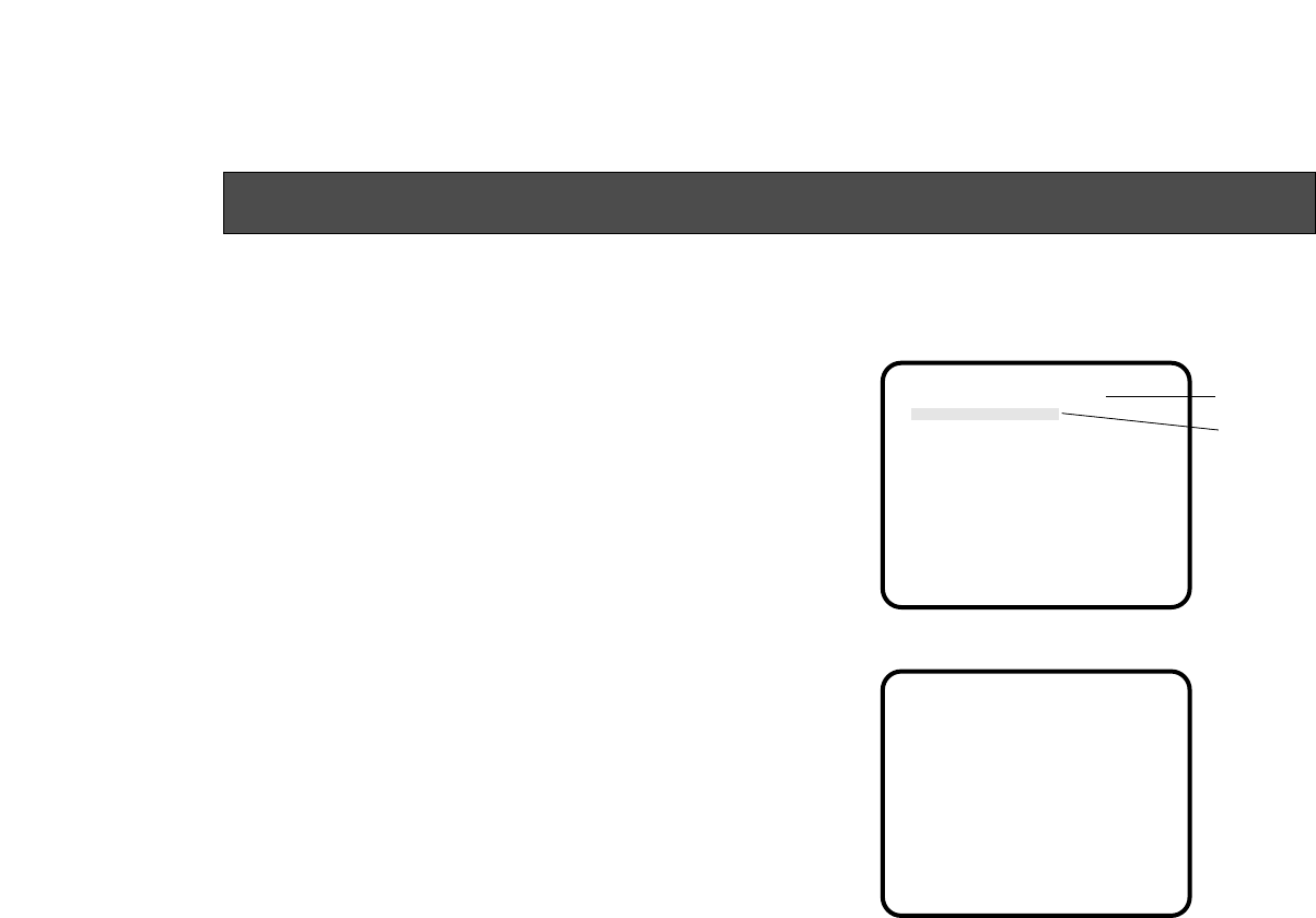
■Setting to initial set
In case of the wrong setting in any use mode, take the
following steps to return to the initial settings.
(1) Select [Initialize Data] on the main menu screen of
each Use Mode. (See page 29.)
Press the YES/ABC switch, then [Initialize Data]
screen shown for about 10 seconds.
(2) Press the YES/ABC switch within about 10 seconds
to return to the initial settings, the existing settings
** Initialize Data **
(Halogen Mode)
Do you want to
initialize Halogen
Mode settings?
O.K. : YES SW
Cancel : NO SW
Halogen Mode
Initialized Halogen Mode
unchanged
qwe
are initialized, the screen shown at w, and the cam-
era returns to main menu.
(3) If the NO/BAR switch is pressed, or if the YES /ABC
switch is not pressed, within about 10 seconds, the
screen shown at e, and the camera returns to main
menu, and the existing settings are not initialized.
SETTING TO INITIAL SET
If you are using an option card, the Option Card
Setting Submenu will not be initialized even if
“Return to Initialize” is performed.
Note

Item
±0
0
Top cut
ON
HIGH
---
–10
MID
G/L. Color
Bar Set
±0
1
±0
7.5 IRE
-47-
■INITIAL SETTINGS OF THE SETTING ITEMS
(Factory preset values)
●Halogen, Fluorescent, Outdoor Mode
Picture Level
Light PEAK/AVG
Light Area
Auto ND (ELC)
Auto Gain Up
Manu Gain Up
Pedestal
Contrast (Gamma)
Brightness
Set
Other Set
Shutter Speed
Synchro Scan
V Resolution
Baud Rate
Nega/Posi
+2
±0
ATW
OFF
Sharpness
HIGH
OFF
OFF
MID
Auto ND
---
Normal
9600bps
Posi
Outdoor mode
+1
±0
AWC A
OFF
±0
1
±0
7.5 IRE
Sharpness
HIGH
OFF
OFF
MID
OFF
---
Normal
9600bps
Posi
±0
0
Top cut
OFF
OFF
0dB
±0
MID
Fluorescent mode
±0
±0
AWC A
OFF
±0
1
±0
7.5 IRE
Sharpness
HIGH
OFF
OFF
MID
OFF
---
Normal
9600bps
Posi
±0
0
Top cut
OFF
OFF
0dB
±0
MID
Halogen mode
Chroma Level
Flesh Tone
White Bal
High-light Chroma
H Phase
SC Coarse
SC Fine
Color Bar Set
DTL Select
Level
Noise Suppress
Clean DNR
DTL Flesh Tone
Color Set
Sharpness
(DTL) Set

-48-
●User Mode
Iris, Shutter,
Gain Set
0.45
88%
110%
0
0
0
OFF
OFF
9600bps
Posi
HIGH
+11
+12
+7
+6
2
3
0%
0
Picture Level
Light PEAK/AVG
Light Area
Auto Iris Adjust
Shutter Mode
Step
Synchro Scan
Field/Frame
Gain
Pedestal
±0
0
Top cut
OFF
Step
OFF
---
Field
0dB
±0
Chroma Level
White Bal
High-light Chroma
Painting R Gain
B Gain
R Pedestal
B Pedestal
2D LPF
Color Set
±0
AWC A
OFF
±0
±0
±0
±0
OFF
H Phase
SC Coarse
SC Fine
Color Bar Set
G/L. Color
Bar Set
±0
1
±0
7.5IRE
Detail
H Detail Level H
V Detail Level H
H Detail Level L
V Detail Level L
Detail Band
Noise Suppress
Level Dependent
Dark Detail
Detail Set 1
Chroma Detail
Flesh DTL Level
Corner Detail
Precision Detail
Detail Set 2
0
MID
OFF
OFF
Matrix(R-G)
Matrix(R-B)
Matrix(G-R)
Matrix(G-B)
Matrix(B-R)
Matrix(B-G)
Color
Matrix Set
±0
±0
±0
±0
±0
±0
Gamma
Knee Point
White Clip
Flare R
Flare G
Flare B
Black Stretch
Clean DNR
Baud Rate
Nega/Posi
Other Set
Item User mode Item User mode
-49-
Convertible Camera AW-
E600E600
84 (3-5/16") 155 (6-3/32")12 (15/32") 10 (25/64")
77 (3-1/32") 10 (25/64")
VIDEO OUT
G/L IN
I/F REMOTE
OPTION CARD
IRIS
DC12V IN
MENU
ITEM/AWC
YES/ABC
NO/BAR
CAUTION
CONNECT TO
SPECIFIED
CLASS 2 POWER
SUPPLY ONLY.
SEE MANUAL.
APPEARANCE
Unit: mm (inch)

-50-
Pickup element: 1/2" interline, supersensitive CCDx3
Pixels: 768 (H) x 494 (V) pixels
Scanning: 2:1 interlace
System: NTSC
Scanning frequency: 15.734 kHz (horizontal), 59.94 Hz (vertical)
Lens mount: 1/2" Standard byonet mount
Synchronizing: Internal or external
External sync input: BB, (BNC,50P D subconnector)
Sensitivity: 2 000 lx, F11, 3 200 K
Minimum illumination: 0.25 lx, F1.4, Night Eye HIGH mode
Signal-to-noise ratio: 65 dB (DNR ON)
Horizontal resolution: 850 TV lines (high band, DTL ON)
Registration: 0.05 %
Contour correction: Horizontal and vertical
White balance: Auto (2 memories), 3 200 K,5 600 K, FINE MANU, ATW
Black balance: AUTO
Color bar: SMPTE color bar (Setup 0/7.5)
Shutter speed: Synchro Scan: 60.34 Hz-15.75 kHz
Step shutter: OFF 1/100, 1/250, 1/500, 1/1 000, 1/2 000, 1/4 000, 1/10 000s
ELC
Gain: AGC LOW/HIGH, 0 - 30 dB, NIGHT EYE LOW/HIGH
Iris: AUTO, MANU
Video output: Composite: 1 V[p-p] (75 Ω) (BNC, 50P D subconnector)
Y: 1 V[p-p] (75 Ω) (50P D subconnector)
C: Same as VBS chroma level (75 Ω) (50P D subconnector)
Use mode: Halogen, Fluorescent, Outdoor, User
SPECIFICATIONS

-51-
Switches: BACK PANEL: MENU, ITEM/AWC, YES/ABC, NO/BAR
MENU ITEM SETTING: Gain, Shutter, White Balance, Detail Level (OFF/LOW/HIGH),
Corner Detail, Precision Detail Level, Black Stretch, High Light Chroma, Skin Color
Detail, Photometric Measurement Method (ALL/CENTER/TOP CUT/BOTTOM CUT/R/L
CUT) CCD Read Out Mode (FIELD/FRAME 1/FRAME 2) Clean DNR, Color Bar Setup,
Use Mode, Nega/Posi, PC Control Access Speed
Adjustment function: MENU ADJUSTMENT: R/B Gain, R/B Pedestal, Black Level, Video Level, Detecting
Ratio, Genlock Horizontal Phase/Color Phase, Gamma Compensation Level, Knee
Compensation Level, White Clip Level, Horizontal Detail Level, Vertical Detail Level,
Detail Band Level, Noise Suppress Compensation Level, Level Dependent
Compensation Level, Chroma Detail Compensation Level, Dark Detail Compensation
Level, Matrix Compensation Level, Flare Correction Level
Source voltage: DC 12 V
Power consumption: 9.6 W
Operating temperature: −10°C to +45°C (14°F to +113°F)
Operating humidity: 30 % to 90 %
Dimensions: 84 (W) x 77 (H) x 155 (D) mm [3-5/16” x 3-1/32” x 6-3/32”]
Weight: 0.86 kg
Finish: AV ivory painting (Munsell 7.9Y 6.8/0.8 or equivalent
Weight and dimensions indicated are approximate.
Specifications are subject to change without notice.

-52-
Pan/Tilt Unit AW-PH300
Pan/Tilt Unit AC Adaptor AW-PS300
Hybrid Control Panel AW-RP501
Multi Hybrid Control Panel AW-RP505
Multi Port Hab AW-HB505
Control Panel AC Adaptor AW-PS301
AC Adaptor AW-PS505
Remote Control Unit WV-RC700A
WV-RC550
Remote Control Box WV-CB700A
Camera Mounting Bracket WV-831
RCU Rack Mount Frame WV-Q70
VF Mounting Bracket AW-Q40
Connection Cable WV-CA9T5
(D sub
9p-BNC,
approx. 5 m)
Studio Cable WV-CA26U15
WV-CA26U30
WV-CA26U100
Cable Joint Adaptor WV-CA26T26
RCB Cable AW-CA50T10
RCU Cable AW-CA50A26
Pan/Tilt Unit Cable AW-CA50T15
PC Control Camera Pan/Tilt Unit Cable AW-CA50A15
PC Control Pan/Tilt Unit Cable AW-CA28T9
PC Control Cable AW-CA50T9
DC Power Cable AW-CA4T1
RGB Cable AW-CA50T6
Studio Card
(RGB, YPr-YPbOutputs) AW-PB301
Studio Card AW-PB305
RGB Card AW-PB302
1/2” Byonet Zoom Lens (14X) AW-LZ14XBMD
Body cap ..................................................................... 1
Rubber Sheet ............................................................... 1
STANDARD ACCESSORIES
OPTIONAL ACCESSORIES

NM1298-0 7J1A256A Printed in Japan
PANASONIC BROADCAST & DIGITAL SYSTEMS COMPANY
DIVISION OF MATSUSHITA ELECTRIC CORPORATION OF AMERICA
Executive Office: 3330 Cahuenga Blvd W., Los Angeles, CA 90068
(323) 436-3500
EASTERN ZONE: One Panasonic Way 4E-7, Secaucus, NJ 07094 (201) 348-7621
Mid-Atlantic: One Panasonic Way 4E-7, Secaucus, NJ 07094 (201) 348-7621
Southeast Region: 1225 Northbrook Parkway, Ste 1-160 Suwanee, GA 30024
(770) 338-6845
Central Region: 1707 N Randall Road E1-C-1, Elgin, IL 60123 (847) 468-5200
WESTERN ZONE: 3330 Cahuenga Blvd W., Los Angeles, CA 90068 (323) 436-3500
Dallas Region: 6226 Abington Way, Houston, TX 77008 (713) 802-2726
Government Marketing Department: 52 West Gude Drive, Rockville, MD 20850 (301) 738-3840
PANASONIC CANADA INC.
5770 Ambler Drive, Mississauga, Ontario, L4W 2T3 (905) 238-2115
PANASONIC SALES COMPANY
DIVISION OF MATSUSHITA ELECTRIC OF PUERTO RICO, INC.
San Gabriel Industrial Park, 65th Infantry Ave., KM9.5 Carolina, Puerto Rico 00630 (809) 750-4300
