Panasonic CW XC123HU User Manual To The 14518db6 842a 4533 897e 711a6c38a471
User Manual: Panasonic CW-XC123HU to the manual
Open the PDF directly: View PDF ![]() .
.
Page Count: 1
- TABLE OF CONTENTS
- SAFETY PRECAUTIONS
- ABOUT THE CONTROLS ON THE AIR CONDITIONER
- CARE AND MAINTENANCE
- FEATURES
- INSTALLATION
- BEFORE YOU CALL FOR SERVICE...
- TABLE OF CONTENTS (SPANISH)
- PRECAUCIONES IMPORTANTES DE SEGURIDAD
- INSTRUCCIONES DE FUNCIONAMIENTO
- CUIDADO Y MANTENIMIENTO
- CARACTERISTICAS
- INSTRUCCIONES DE INSTALACION
- ANTES DE AVISAR AL SERVICIO TECNICO
INSTALLATION AND
OPERATING INSTRUCTIONS
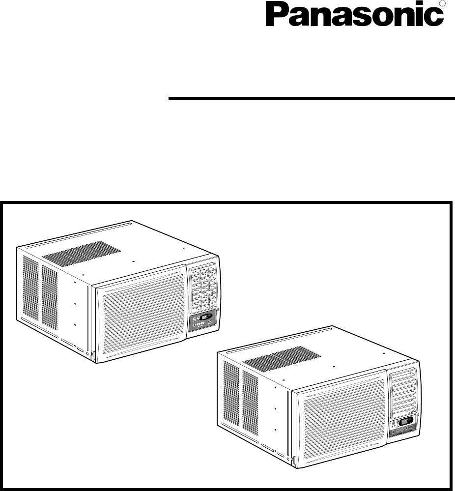
Room Air Conditioner
Models: CW-XC103HU
CW-XC123HU
CW-XC143HU
CW-XC118HU
Please read these operating instructions thoroughly
before using your air conditioner and keep for future
reference.
For assistance, please call: 1-800-211-PANA(7262) or
Register your product at : http://www.panasonic.com/register
R

2
Safety Precautions
About the Controls on the Air Conditioner
Features and Installation
Before you call for service...
3
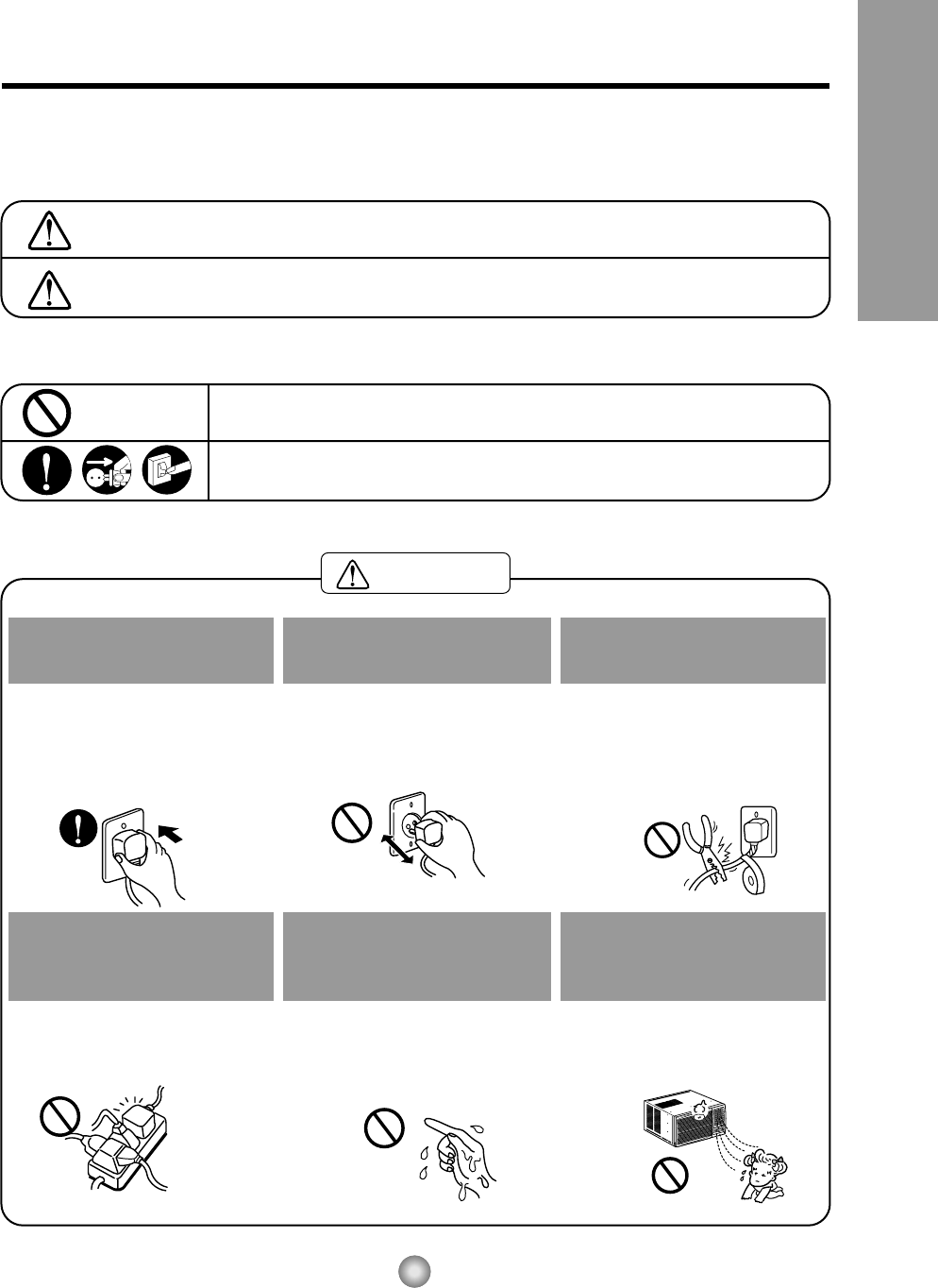
Safety Precautions
WARNING
Safety Precautions
To prevent injury to the user or other people and property damage, the following instructions must be
followed.
■Incorrect operation due to ignoring of instruction will cause harm or damage. The seriousness is classified
by the following indications.
WARNING : This symbol indicates the possibility of death or serious injury.
CAUTION :This symbol indicates the possibility of injury or damage to
property only.
■Meanings of symbols used in this manual are as shown below.
Be sure not to do this.
Be sure to follow the instructions.
Plug in the power plug
properly.
• Otherwise, it will cause electric
shock or fire due to heat
generation.
Do not operate or stop the
unit by inserting or pulling
out the power plug.
• It will cause electric shock or fire
due to heat generation.
Do not damage or use an
unspecified power cord.
• It will cause electric shock or fire.
•
If the power cord is damaged, it must
be replaced by the manufacturer or
an authorized service center or a
similarly qualified person in order to
avoid a hazard.
Do not modify power cord
length or share the outlet
with other appliances.
• It will cause electric shock or fire
due to heat generation.
Do not operate with wet
hands or in a damp
environment.
• It will cause electric shock.
Do not direct airflow at room
occupants.
• This could damage your health.
4
Safety Precautions


9
Features and Installation
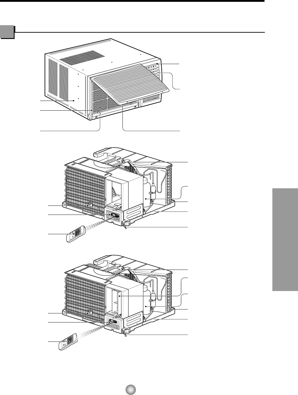
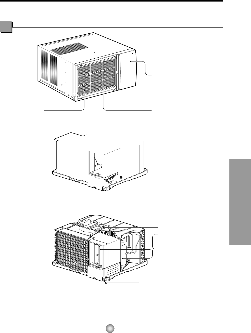
Learning parts name prior to installation will help you understand the installation procedure.
Features
Features
CABINET
FRONT GRILLE
AIR FILTER AIR INTAKE
(INLET GRILLE)
AIR DISCHARGE
VERTICAL AIR DEFLECTOR
(HORIZONTAL LOUVER)
EVAPORATOR
CONTROL BOARD
REMOTE
CONTROLLER
POWER CORD
BASE PAN
CONDENSER
COMPRESSOR
BRACE
HORIZONTAL AIR DEFLECTOR
(VERTICAL LOUVER)
EVAPORATOR
CONTROL BOARD
REMOTE
CONTROLLER
POWER CORD
BASE PAN
CONDENSER
COMPRESSOR
BRACE
Model: CW-XC103HU
CW-XC123HU
CW-XC143HU
Model: CW-XC118HU
10
Features and Installation
27" to 39"
Offset
1/2" to 11/4"
Sill
Exterior
Interior wall
23 5/8" min.
(Without frame curtain)
Stool
16" min
(With frame curtain)
About 1/2"
30"~60"
Awning
Cooled air
Fence
Over 20"
Heat
radiation
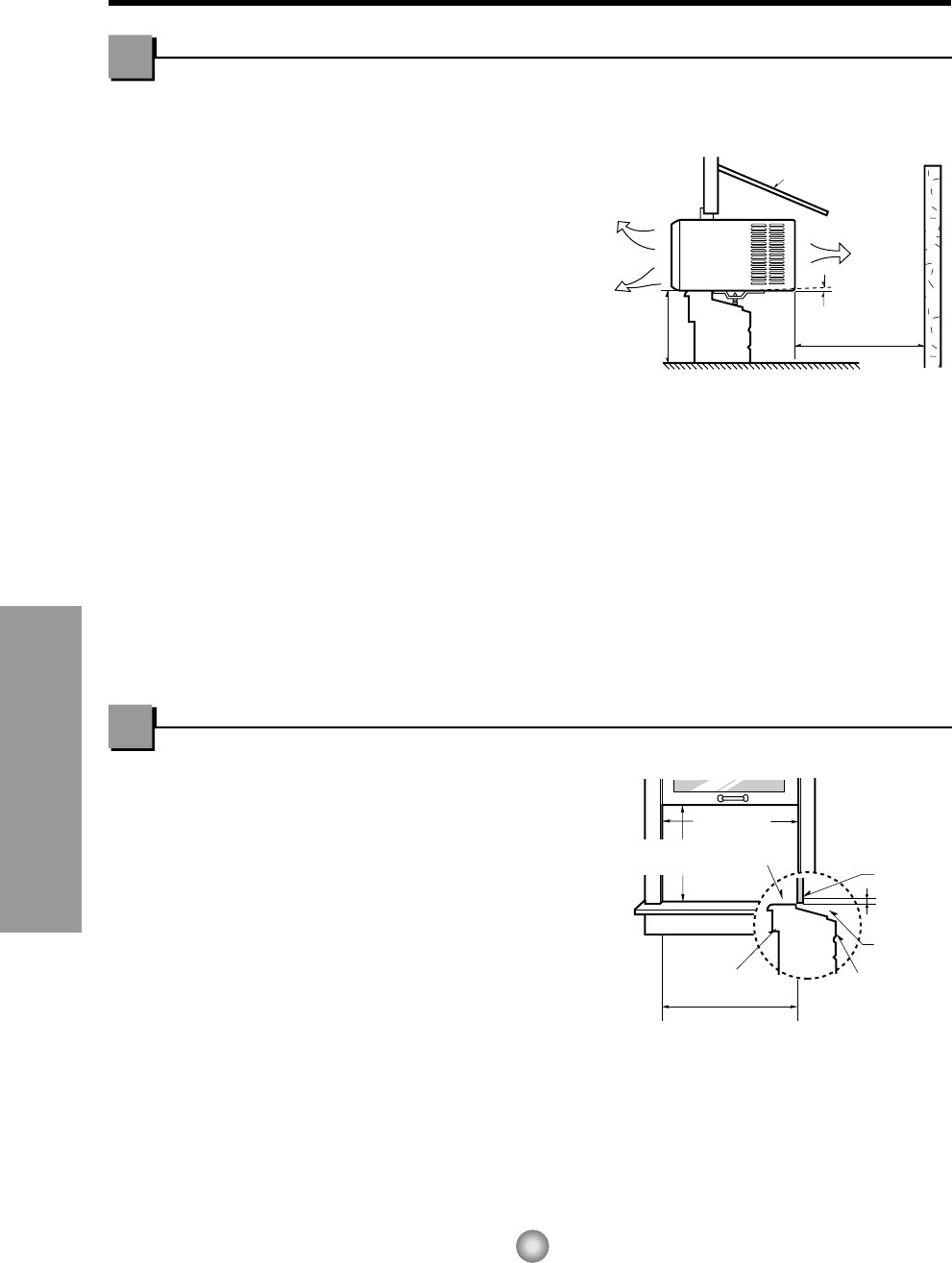
Installation
1. To prevent vibration and noise, make sure
the unit is installed securely and firmly
2. Install the unit where the sunlight does not
shine directly on the unit.
3. The outside of the cabinet must extend
outward for at least 12" and there should
be no obstacles, such as a fence or wall,
within 20" from the back of the cabinet
because it will prevent heat radiation of the
condenser.
Restriction of outside air will greatly reduce
the cooling efficiency of the air conditioner.
CAUTION: All side louvers of the cabinet must remain exposed to the outside of the
structure.
4. Install the unit a little slanted so the back is slightly lower than the front(about 1/2").
This will force condensed water to flow to the outside.
5. Install the unit with the bottom about 30"~60" above the floor level.
Window Requirements
NOTE: All supporting parts should be secured to firm wood, masonry, or metal.
This unit is designed for installation in
standard double hung windows with actual
opening widths from 27" to 39".
The top and bottom window sash must open
sufficiently to allow a clear vertical opening of
16" from the bottom of the upper sash to the
window stool.
How to Install the Unit
11
Features and Installation
9
10
9
5
5
5
11
11
(Type A)
(Type A)
13
Shipping
Screws
12 3 4
8 13
14
10
765
9
12
11
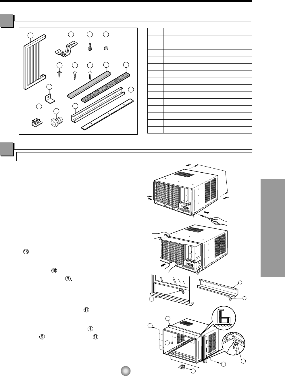
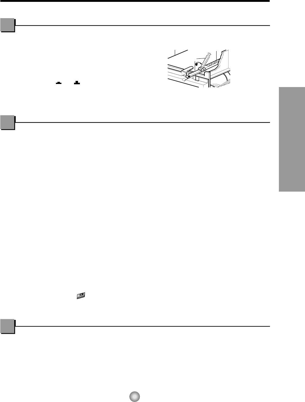
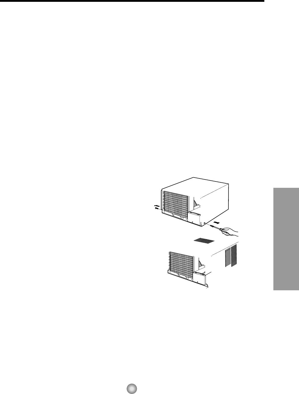
PREPARATION OF CHASSIS
1. Remove the screws which fasten the cabinet
at both sides and at the back.
2. Slide the unit from the cabinet by gripping the
base pan handle and pulling while bracing the
cabinet.
3. Cut the window sash seal to the proper
length.
Peel off the backing and attach the FOAM-PE
to the underside of the window sash.
4. Remove the backing from the top upper guide
FOAM-PE and attach it to the bottom of
the upper guide
5. Attach the upper guide onto the top of the
cabinet with 3 type A screws.
6. Insert the frame guides into the bottom of
the cabinet.
7. Insert the Frame Curtain into the upper
guide and frame guides .
8. Fasten the curtains to the unit with 4 Type
A screws.
Suggested Tool Requirements
Installation Kits Contents
SCREWDRIVER(+, -), RULER, KNIFE, HAMMER, PENCIL, LEVEL
NO. NAME OF PARTS Q'TY
1 FRAME CURTAIN 2
2 SILL SUPPORT 2
3 BOLT 2
4 NUT 2
5
SCREW(TYPE A) (10mm(2/5"))
16
6
SCREW(TYPE B)
3
7
SCREW(TYPE C)
5
8 FOAM-STRIP 1
9 UPPER GUIDE 1
10
FOAM-PE (600mm x 25mm x 2mm)
1
11 FRAME GUIDE 2
12
WINDOW LOCKING BRACKET
1
13
FOAM-PE
(920mm x 30mm x 2mm)
1
14 DRAIN PIPE 1
D5.1mm(0.2")
16mm(0.63")
D4.1mm(0.17")
16mm(0.63")
12
Features and Installation
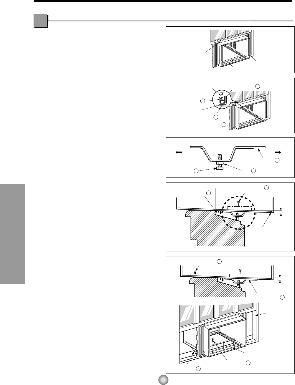
Upper Guide
Window Sash
Window sill
Front Angle
Upper guide
9
Frame Curtain
1
Foam-pe
10
Foam-pe
13
Cabinet
INDOOR OUTDOOR
INDOOR OUTDOOR
Sash track
Front Angle
Cabinet
About 1/2"
About 1/2"
Sill Support
2
Nut
4
Bolt
3
Frame Guide
11
Screw (Type B)
6
Screw (Type B)
6
Sill support
2
Sill support
2
Screw (Type A)
5
13
Features and Installation
Type C
7
Screw (Type A)
Screw (Type A)
Power cord
Foam-Strip
8
Window locking bracket
12
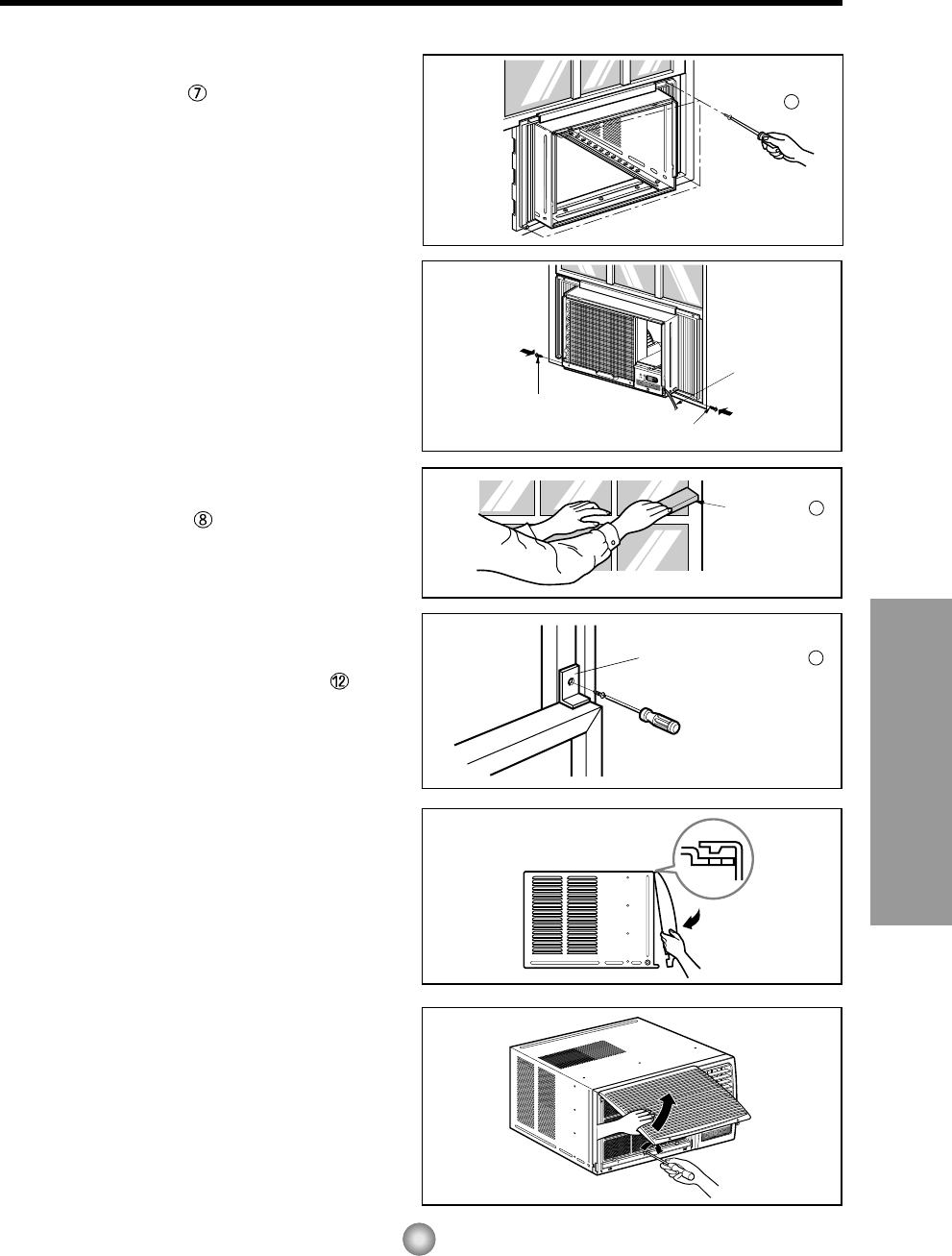
9. Attach each Frame curtain to the window
sash using screws (Type C). (See Fig. 6)
CAUTION: DO NOT DRILL A HOLE IN THE
BOTTOM PAN.
The unit is designed to operate
with approximately 1/2" of water in
bottom pan.
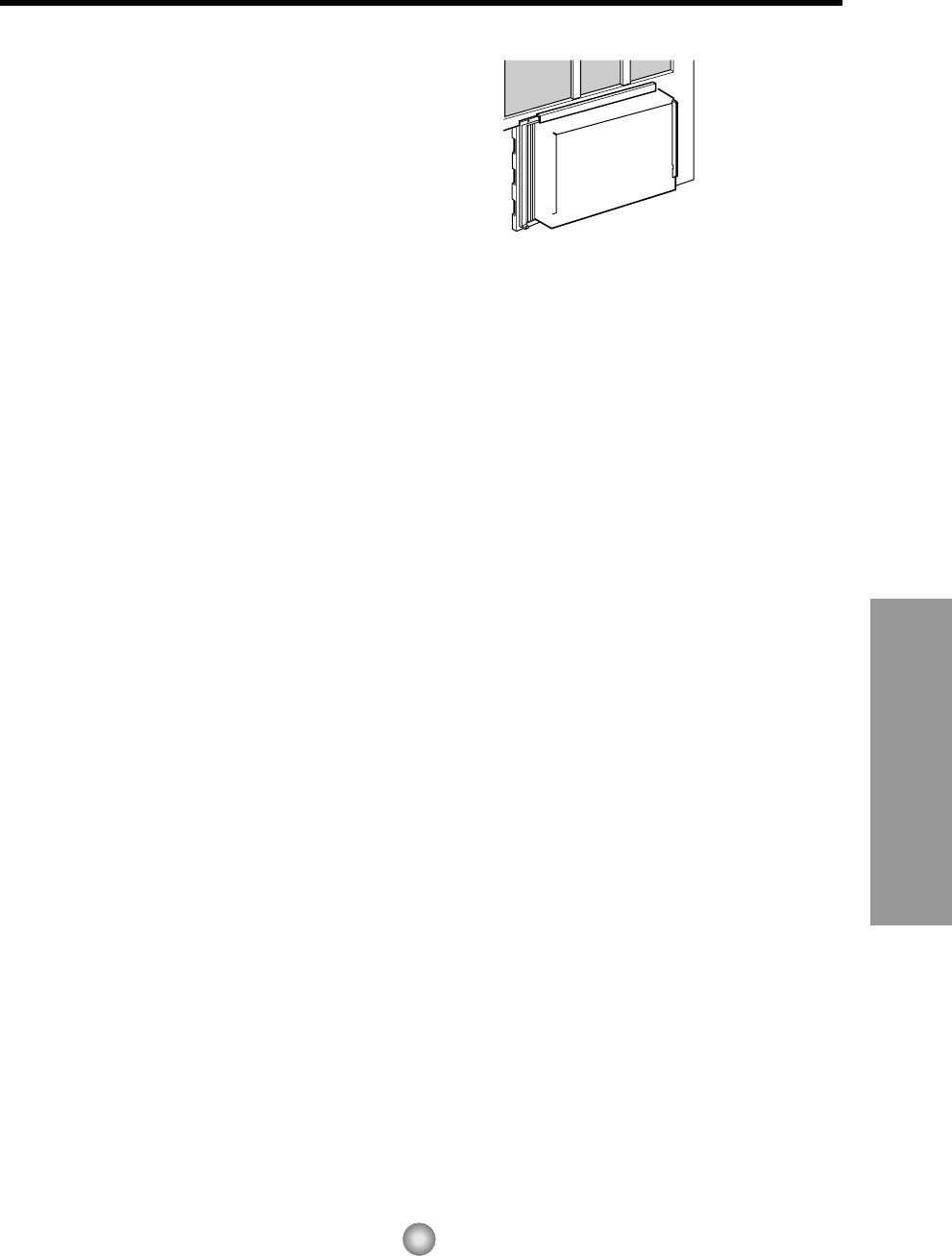
10. Slide the unit into the cabinet. (See Fig. 7)
CAUTION: For security purpose, reinstall
screws (Type A) at cabinet's sides.
11. Cut the foam-strip to the proper length
and insert between the upper window sash
and the lower window sash.
(See Fig. 8)
12. Attach the window locking bracket with
a type C screw. (See Fig. 9)
13. Attach the front grille to the cabinet by
inserting the tabs on the grille into the tabs
on the front of the cabinet. Push the grille
in until it snaps into place. (See Fig.10)
NOTE: Please refer page 7 for setting the
ventilation knob.
14. Lift the inlet grille and secure it with a type
A screw through the front grille.
(See Fig. 11)
15. Window installation of room air conditioner
is now completed. See ELECTRICAL DATA
for attaching power cord to electrical outlet.
Fig. 6
Fig. 7
Fig. 8
Fig. 9
Fig. 10
Fig. 11
14
Features and Installation
Do not under any
circumstances cut
or remove the
grounding prong
from the plug.
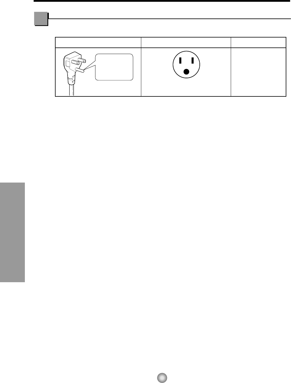
Line Cord Plug Use Wall Receptacle Power Supply
Power supply cord with
3-prong grounding plug Standard 125V, 3-wire grounding
receptacle rated 15A, 125V AC
Use 15 AMP, time
delay fuse or circuit
breaker.
Electrical Data
USE OF EXTENSION CORDS
Because of potential safety hazards, we strongly discourage the use of an extension cord. However, if you
wish to use an extension cord, use a CSA certified/UL-listed 3-wire (grounding) extension cord, rated 15A,
125V.
15
Features and Installation
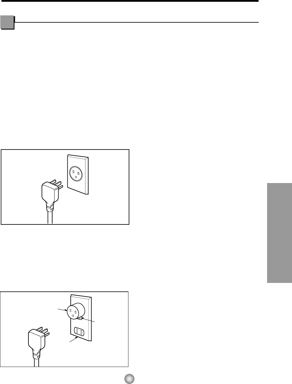
PREFERRED METHOD
Ensure proper ground
exists before use
TEMPORARY METHOD
Adapter plug
Receptacle cover
Metal screw
Electrical Safety
IMPORTANT
(PLEASE READ CAREFULLY)
FOR THE USER'S PERSONAL SAFETY, THIS
APPLIANCE MUST BE PROPERLY GROUNDED
The power cord of this appliance is equipped with a
three-prong (grounding) plug. Use this with a
standard three-slot (grounding) wall power outlet
(Fig. 16) to minimize the hazard of electric shock.
The customer should have the wall receptacle and
circuit checked by a qualified electrician to make
sure the receptacle is properly grounded.
DO NOT CUT OR REMOVE THE THIRD
(GROUND) PRONG FROM THE POWER PLUG.
A. SITUATIONS WHERE THE APPLIANCE
WILL BE DISCONNECTED ONLY
OCCASIONALLY:
Because of potential safety hazards, we strongly
discourage the use of an adapter plug. However, if
you wish to use an adapter, a TEMPORARY
CONNECTION may be made. Use UL-listed
adapter, available from most local hardware stores
(Fig. 17). The large slot in the adapter must be
aligned with the large slot in the receptacle to
assure a proper polarity connection.
CAUTION: Attaching the adapter ground terminal to
the wall receptacle cover screw does not ground the
appliance unless the cover screw is metal, and not
insulated, and the wall receptacle is grounded
through the house wiring.
The customer should have the circuit checked by a
qualified electrician to make sure the
receptacle is properly grounded.
Disconnect the power cord from the adapter, using
one hand on each. Otherwise, the adapter ground
terminal might break. DO NOT USE the appliance
with a broken adapter plug.
B. SITUATIONS WHERE THE APPLIANCE
WILL BE DISCONNECTED OFTEN.
Do not use an adapter plug in these situations.
Unplugging the power cord frequently can lead to
an eventual breakage of the ground terminal. The
wall power outlet should be replaced by a three-slot
(grounding) outlet instead.
USE OF EXTENSION CORDS
Because of potential safety hazards, we strongly
discourage the use of an extension cord. However,
if you wish to use an extension cord, use a CSA
certified/UL-listed 3-wire (grounding) extension
cord, rated 15A, 125V.
Fig. 16
Fig. 17
16
Before you call for service...
Before you call for service...
Before you call for service...
Troubleshooting Tips Save time and money!
Review the chart below first and you may not need to call for service.
Problem Possible Causes What To Do
■ The air conditioner is
unplugged.
■ The fuse is blown/circuit
breaker is tripped.
■ Power failure.
■ Airflow is restricted.
■ TEMP Control set too
higher number.
■ The air filter is dirty.
■ The room may have been
hot.
■ Cold air is escaping.
■ Cooling coils have iced up.
■ Ice blocks the air flow and
stops the air conditioner
from cooling the room.
• Make sure the air conditioner plug is pushed
completely into the outlet.
• Check the house fuse/circuit breaker box and
replace the fuse or reset the breaker.
• When power is restored, wait 3 minutes to restart the
air conditioner to prevent tripping of the compressor
overload.
• Make sure there are no curtains, blinds, or furniture
blocking the front of the air conditioner.
• Set the TEMP Control to a lower number.
• Clean the filter at least every 2 weeks.
See the operating instructions section.
• When the air conditioner is first turned on
you need to allow time for the room to cool down.
• Check for open furnace floor registers
and cold air returns.
• Set the air conditioner's vent to the closed position.
• See Air Conditioner Freezing Up below.
• Set the mode control at High Fan or High Cool with
the high temperature.
Air conditioner
does not start
Air conditioner
does not cool as it
should
Air conditioner
freezing up
Normal Operation
• You may hear a pinging noise caused by water being picked up and thrown against the condenser
on rainy days or when the humidity is high. This design feature helps remove moisture and improve
efficiency.
• You may hear the thermostat click when the compressor cycles on and off.
• Water will collect in the base pan during high humidity or on rainy days. The water may overflow
and drip from the outdoor side of the unit.
• The fan may run even when the compressor does not.
Abnormal Operation

17
Memo
18
Precauciones Importantes de seguridad
Instrucciones de Funcionamiento
Características e Instalacion
Antes de avisar al Servicio Técnico
Precauciones Importantes de seguridad
ADVERTENCIA
19
Precauciones Importantes de Seguridad
Para prevenir tanto lesiones al usuario u otras personas como daños materiales, es preciso seguir estas instrucciones.
■El manejo incorrecto debido a la inobservancia de estas instrucciones puede causar lesiones o daños cuya gravedad
está clasificada en las siguientes indicaciones.
ADVERTENCIA Este símbolo indica la posibilidad de lesiones mortales o graves.
PRECAUCION
Este símbolo indica la posibilidad de lesiones o daños
materiales.
■
El significado de los símbolos utilizados en este manual se indica a continuación.
Asegúrese de no hacerlo.
Asegúrese de seguir las instrucciones.
Conecte correctamente el
enchufle
• De otra forma, ello ocasionaría
una descarga eléctrica o
incendio a causa de la
generación de calor.
No opere o pare la unidad
insertando o tirando del
enchufe
• Ello ocasionaría una descarga
eléctrica o incendio a causa de la
generación de calor.
No dañe o utilize un cable
eléctrico inadecuado
• Ello ocasionaría una descarga
eléctrica o incendio.
No modifique el largo del cable
eléctrico, y tampoco comparta
el tomacorriente con otros
aparatos
• Ello ocasionaría una descarga
eléctrica o incendio a causa de la
generación de calor.
No lo maneje con las manos
humedas
• Puede ocasionar una descarga
eléctrica.
No exponga durante mucho
tiempo la piel al aire frío
procedente directamente del
acondicionador.
• Esto podría dañar su salud.

21
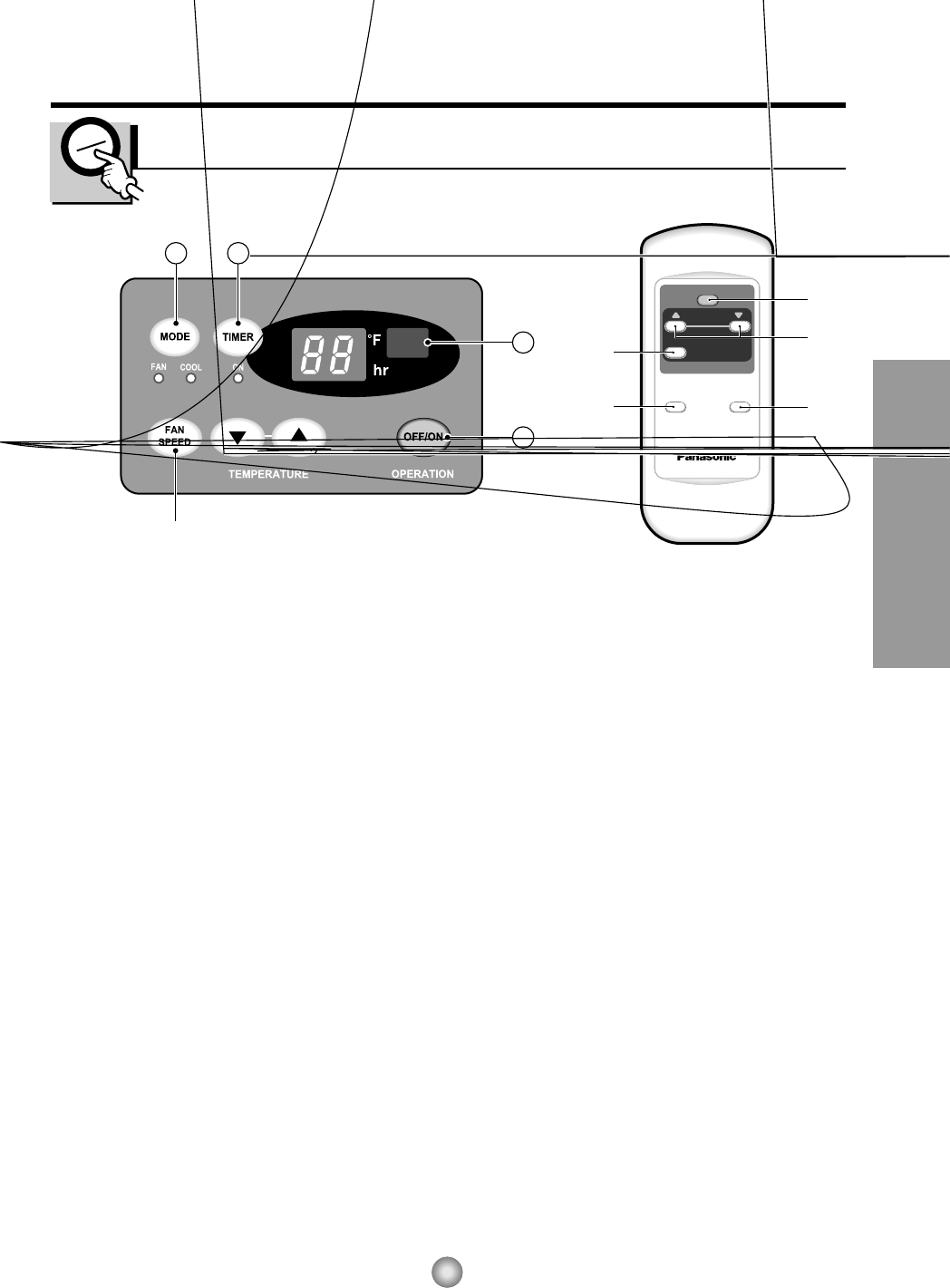
Instrucciones de Funcionamiento
OPERATION
TEMP
TIMER
MODE FAN SPEED
32
1
6

23
Instrucciones de Funcionamiento
VENTCERRADO ABIERTO
Parte
Parte

25
Características e Instalacion
Aprender el nombre de las partes antes de la instalación le ayudará a entender el proceso
de instalación.
Características
Características

27
Características e Instalacion

29
Características e Instalacion


31
Características e Instalacion
MÉTODO PREFERIDO
ASEGÚRESE QUE EXISTE
DEBIDA NEUTRALIZACIÓN ANTES
DE UTILIZAR EL APARATO.
MÉTODO TEMPORAL
Adaptador
Cubierta del interruptor
Tornillo de metal
Informacion Electrica
IMPORTANTE
(FAVORLEA CON ATENCIÓN)
POR LA SEGURIDAD PERSONAL DEL
USUARIO, ESTE APARATO DEBE SER
DEBÍDAMENTE NEUTRALIZADO.
El cordón de energía de éste aparato esta
equipado con tres patas(cable a tierra). Utilice
éste con un enchufe de pared de tres salidas(a
tierra)(Fig. 16) para minimizar el peligro de
choque eléctrico. El cliente debe revisar el
receptor de pared y el circuito por un
electricista calificado para asegurarse que la
recepción esta debidamente neutralizada.
NO CORTE O REMUEVA LA TERCERA
PATA(GROUND) DEL ENCHUFE.
A. SITUACIONES EN LAS CUALES EL
APARATO ES DESCONECTADO
OCASIONALMENTE:
Debido al peligro potencial, nosotros no
recomendamos el uso de adaptadores. Sin
embargo, si usted desea utilizar un adaptador,
una CONEXIÓN TEMPORAL, puede ser
efectuada. Utilice adaptadores UL, disponibles
en la mayoría de los estable cimientos de
herramientas(Fig. 17). La pata mas grande del
adaptador debe ser alineada con la pata mas
grande del interruptor para asegurarse una
polarización adecuada.
CUIDADO: Adaptar la terminal del ground del
adaptador a la cubierta de la pared con un
tornillo no neutraliza el aparato a menos que la
cubierta del tornillo sea de metal, u no sea
insolada, y el receptor de pared este
neutralizado a través del alambrado del la
casa. El cliente debe hacer verificar el circuito
por un electricista calificado para asegurarse
que el receptor esta debidamente neutralizado.
Desconecte el cordón de energía del
adaptador, utilizado una mano en cada uno.
De lo contrario, la terminal del adaptador
puede romperse. NO UTILICE el aparato con
un enchufe roto.
B. SITUACIONES EN LAS CUALES EL
APARATO ES DESCONECTADO CON
FRECUENCIA.
No utilice un adaptador en estas
circunstancias. Desconectar el cordón de
energía con frecuencia lo llevará al eventual
rompimiento de la terminal de neutralización.
La saluda de energía de la pared debe ser
reemplazada por una salida de tres
patas(neutralizada).
USO DE EXTENSIONES
Debido al peligro potencial, no recomendamos
la utilización de extensiones. Sin embargo, si
usted desea utilizar una extensión, utilice una
certificada por CSA/UL de tres alambres,
catalogada 15A, 125V.
Fig. 16
Fig. 17


33
Model
Modèle
Modelo
COOLING CAPACITY Btu/h 9,800 11,800
CAPACITÉ DE REFROIDISSEMENT
CAPACIDAD DE ENFRIAMIENTO
ELECTRICAL RATING Phase Single Single
CARACTÉRISTIQUES ÉLECTRIQUES Phase Simple Simple
CLASIFICION DE LA ELECTRICIDAD Fase Monofasico Monofasico
Frequency (Hz) 60 60
Fréquence
Frecuencia
Voltage (V) 115 115
Tension
Voltaja
Current (Amps) 8.4 10.0
Courant (A)
Corriente (Amps)
Input (W) 910 1,090
Consommation
Potencia
EER
RENDEMENT ÉNERGÉTIQUE 10.8 10.8
EER
MOISTURE REMOVAL (Pints/h)
SUPPRESSION D'HUMIDITÉ(pinte/h) 3.3 3.0
DESHUMIDIFICACION (Tinta/h)
ROOM CIRCULATION (Cf/min)
CIRCULATION D'AIR (pi/min) 265 290
CIRCULACION DE AIRE (pie/min)
DIMENSIONS Height cm(inches)
DIMENSIONS Hauteur cm(pouces) 38.0(14 31/32) 38.0(14 31/32)
DIMENSIONES Alto cm(pulgadas)
Width cm(inches)
Largeur cm(pouces) 60.0(235/8) 60.0(235/8)
Ancho cm(pulgadas)
Depth cm(inches)
Profondeur cm(pouces) 56.7(22 5/16) 56.7(22 5/16)
Profundidad cm(pulgadas)
NET WEIGHT kg(Ib)
POIDS NET kg(livres) 43(95) 45(100)
PESO NETO kb(libras)
GROSS WEIGHT kg(Ib)
POIDS BRUT kg(livres) 45(100) 47(105)
PESO BRUTO kb(libras)
PRODUCT SPECIFICATION
ESPECIFICIONES DEL PRODUCTO
* Specifications are subject to change without notice for improvement.
* Les spécifications ci-dessus peuvent être changées sans préavis.
* Las especificacionas están sujetas a cambios por majoras sin previo aviso.
CW-XC103HU CW-XC118HU


35
Nota

Panasonic Room Air Conditioner
Limited Warranty
Panasonic Consumer Electronics Company or Panasonic Sales Company (collectively referred to as "the Warrantor") will repair
this product with new or refurbished parts in case of defects in material or workmanship, free of charge, in the USA or Puerto
Rico in accordance to the following (All time periods start from the date of the original purchase).
SEALED REFRIGERATING SYSTEM (compressor and interconnecting tube): FIVE (5) YEARS - PARTS AND LABOR
ALL OTHER COMPONENTS: ONE (1) YEAR - PARTS AND LABOR
In-home service in the USA can be obtained during the warranty period by contacting a Panasonic Service Company (PASC)
Factory Servicenter listed in the Servicenter Directory. Or call toll free, 1-800-211-PANA(7262), to locate a PASC authorized
Servicenter. In-home service in Puerto Rico can be obtained during the warranty period by calling the Panasonic Sales Company
telephone number listed in the Servicenter Directory.
Note: If the unit is installed at the other than normal window height and/or has been
custom-installed (e.g., through the wall), the customer is responsible for removing
the unit from its installation prior to the performance of in-home service.
This warranty is extended only to the original purchaser. A purchase receipt or other proof of date of the original purchase is
required for service and parts replacement under this warranty.
This warranty only covers failures due to defects in materials and workmanship and does not cover normal wear or cosmetic
damage. The warranty does not cover damages which occur in shipment, or failures which are caused by products not supplied by
the warrantor, or failures which result from accident, misuse, abuse, neglect, mishandling, misapplication, faulty installation,
maladjustment of customer controls, improper maintenance, alteration, modification, power line surge, lightning damage,
improper voltage supply, commercial use such as hotel, office, restaurant, or other business or rental use of the product, or service
by anyone other than a PASC Factory Servicenter or a PASC authorized Servicenter, or damage that is attributable to acts of God.
LIMITS AND EXCLUSIONS
There are no express warranties except as listed above.
THE WARRANTOR SHALL NOT BE LIABLE FOR INCIDENTAL OR CONSEQUENTIAL DAMAGES RESULTING
FROM THE USE OF THIS PRODUCT, OR ARISING OUT OF ANY BREACH OF THIS WARRANTY ALL EXPRESS AND
IMPLIED WARRANTIES, INCLUDING THE WARRANTIES OF MERCHANTABILITY, ARE LIMITED TO THE
APPLICABLE WARRANTY PERIOD SET FORTH ABOVE.
Some states do not allow the exclusion or limitation of incidental or consequential damages or limitations on how long an
implied warranty lasts, so the above exclusions or limitations may not apply to you.
This warranty gives you specific legal rights and you may also have other rights which vary from state to state If a problem with
this product develops during or after the warranty period, you may contact your dealer or Servicenter If the problem is not
handled to your satisfaction, then write to the Consumer Affairs Department at the company address indicated above
SERVICE CALLS WHICH DO NOT INVOLVE DEFECTIVE MATERIALS OR WORKMANSHIP AS DETERMINED BY
THE WARRANTOR, IN ITS SOLE DISCRETION, ARE NOT COVERED COSTS OF SUCH SERVICE CALLS ARE THE
RESPONSIBILITY OF THE PURCHASER.
[For assistance, please call: 1-800-21 1-PANA (7262) or send e-mail to consumerproducts@panasonic.com]
Printed in Korea
Panasonic Consumer Electronics Company,
Division of Matsushita Electric Corporation
of America
One Panasonic Way
Secaucus, New Jersey 07094
Panasonic Sales Company,
Division of Matsushita Electric of Puerto Rico, Inc.,
Ave. 65 de Infanteria, Km. 9.5
San Gabriel Industrial Park
Carolina, Puerto Rico 00985
P/No.: 3828A20046E
