Panasonic KV S6055W S6050L User Manual To The C2bd800e F20d 40a8 B876 402d92830789
User Manual: Panasonic KV-S6055W to the manual
Open the PDF directly: View PDF ![]() .
.
Page Count: 67
- System requirements
- Notice
- Precautions
- Component Identification
- Display Panel Instructions
- Loading Documents on the ADF
- Loading Documents on the Flatbed
- Feeding a Document Manually
- Others
- Clearing Paper Jams
- Cleaning the Unit
- Replacing Consumable Roller Modules
- Repacking Instructions
- Specifications
- Troubleshooting
- Index
Model No. KV-S6050W / KV-S6055W /
KV-S6050WU / KV-S6055WU
These instructions contain the information on operating the scanner. Before reading these
instructions, please go through the installation manual enclosed with this unit.
Please carefully read these instructions, the enclosed installation manual and maintenance
manual. Keep these documentation in a safe place for future reference.
Keep the CD-ROM in the protective case. Do not expose the CD-ROM to direct sunlight or
extreme heat and do not scratch or smudge the surface of the CD-ROM.
2
Thank you for purchasing a Panasonic “High Speed Scanner”.
•
For the versatile solution for imaging needs, Panasonic developed Panasonic Image Enhancement Technology to
improve the quality of your originals.
•
Red and Green lamp setting right from the display panel to select dropout color quite easily. (Only back scanning
for KV-S6055W)
•
With these easy-to-use functions, reliable paper handling, easy maintenance and more, Panasonic would like to
contribute to your imaging needs.
•
Difference between the KV-S6055W and KV-S6050W is only the contact image sensor for back scanning.
Please refer to page 59 “Specifications” for details.
∫∫
∫∫
System requirements
When using the scanner, the required host computer conditions are as follows.
§
The scanning speed differs depending on the host computer operating environment or application.
As an E
NERGY
S
TAR
® Partner, Panasonic has determined that this product meets the
E
NERGY
S
TAR
® guidelines for energy efficiency.
(E
NERGY
S
TAR
is a U.S. registered mark.)
•
Windows
®
95 is Microsoft
®
Windows
®
95 operating system.
•
Windows
®
98 is Microsoft
®
Windows
®
98 operating system.
•
Windows NT
®
is Microsoft
®
Windows NT
®
operating system.
•
Windows
®
2000 is Microsoft
®
Windows
®
2000 operating system.
•
Microsoft
®
, Windows
®
and Windows NT
®
are either registered trademarks or trademarks of Microsoft Corporation
in the United States and / or other countries.
•
Pentium
®
is a registered trademark of Intel Corporation.
•
Celeron™ is trademark of Intel Corporation.
•
Each company’s name or company product name is each company’s trademark or registered trademark.
The information given in these Operating Instructions is subject to change without notice.
CPU
Pentium
®
166MHz or higher (Pentium
®
III
, Celeron™ processor or higher is recommended.)
Memory
(RAM) 64 MB or higher (128 MB or higher is recommended.)
OS
Windows
®
95 / Windows
®
98 / Windows NT
®
/ Windows
®
2000 / Windows
®
Me
SCSI board
Adaptec SCSI card 2930 / 2940 / 19160 / 29160N Series are recommended.
Important
•
Do not duplicate currency.
•
Do not duplicate copyrighted material or the work of others except for the purpose of private use.
•
Do not duplicate any kind of certificates, licenses, passports, official or private documents, and the like.

3
Page
Notice . . . . . . . . . . . . . . . . . . . . . . . . . . . . . . . . . . . . . . . . . . . . . . . 4
Precautions. . . . . . . . . . . . . . . . . . . . . . . . . . . . . . . . . . . . . . . . . . 10
Component Identification . . . . . . . . . . . . . . . . . . . . . . . . . . . . . . . 13
Display Panel Instructions . . . . . . . . . . . . . . . . . . . . . . . . . . . . . .15
•
Display panel and keys . . . . . . . . . . . . . . . . . . . . . . . . . . . . . . . . . . . . . . . . . 15
•
Setting the language . . . . . . . . . . . . . . . . . . . . . . . . . . . . . . . . . . . . . . . . . . . 16
•
Setting the scanner . . . . . . . . . . . . . . . . . . . . . . . . . . . . . . . . . . . . . . . . . . . . 17
Loading Documents on the ADF . . . . . . . . . . . . . . . . . . . . . . . . .34
Loading Documents on the Flatbed . . . . . . . . . . . . . . . . . . . . . .37
•
When scanning with the flatbed one time . . . . . . . . . . . . . . . . . . . . . . . . . . . 37
•
When scanning with the flatbed repeatedly . . . . . . . . . . . . . . . . . . . . . . . . . . 38
•
Scanning thick documents . . . . . . . . . . . . . . . . . . . . . . . . . . . . . . . . . . . . . . . 39
Feeding a Document Manually . . . . . . . . . . . . . . . . . . . . . . . . . . .40
Others . . . . . . . . . . . . . . . . . . . . . . . . . . . . . . . . . . . . . . . . . . . . . . . 41
•
How to use the control sheet . . . . . . . . . . . . . . . . . . . . . . . . . . . . . . . . . . . . . 41
Clearing Paper Jams . . . . . . . . . . . . . . . . . . . . . . . . . . . . . . . . . . .42
•
Removing paper jams from the feed part . . . . . . . . . . . . . . . . . . . . . . . . . . . 42
•
Removing paper jams from the exit path . . . . . . . . . . . . . . . . . . . . . . . . . . . . 43
Cleaning the Unit . . . . . . . . . . . . . . . . . . . . . . . . . . . . . . . . . . . . . . 44
•
Outside of the scanner . . . . . . . . . . . . . . . . . . . . . . . . . . . . . . . . . . . . . . . . . 44
•
Inside the scanner . . . . . . . . . . . . . . . . . . . . . . . . . . . . . . . . . . . . . . . . . . . . . 44
•
Cleaning the rollers . . . . . . . . . . . . . . . . . . . . . . . . . . . . . . . . . . . . . . . . . . . . 44
•
Cleaning the scanning section glass, CIS glass, sensor plate,
sensor roller, document sensors, double feed detection
sensors and paper detection sensor . . . . . . . . . . . . . . . . . . . . . . . . . . . . . . . 47
•
Document glass and cover sheet . . . . . . . . . . . . . . . . . . . . . . . . . . . . . . . . . 51
•
Roller cleaning paper . . . . . . . . . . . . . . . . . . . . . . . . . . . . . . . . . . . . . . . . . . . 51
Replacing Consumable Roller Modules . . . . . . . . . . . . . . . . . . . 52
Repacking Instructions . . . . . . . . . . . . . . . . . . . . . . . . . . . . . . . . 58
Specifications . . . . . . . . . . . . . . . . . . . . . . . . . . . . . . . . . . . . . . . .59
Troubleshooting . . . . . . . . . . . . . . . . . . . . . . . . . . . . . . . . . . . . . . 61
Index . . . . . . . . . . . . . . . . . . . . . . . . . . . . . . . . . . . . . . . . . . . . . . . .65
§
German display on the display panel is described on page 16.
Operation
Care
Appendix
Before You
Start
Table of Contents
and
Maintenance

4
Notice
Federal Communications Commission Requirements
(For United States only)
Note : This equipment has been tested and found to comply with the limits for a Class A digital device, pursuant to
part 15 of the FCC Rules. These limits are designed to provide reasonable protection against harmful
interference when the equipment is operated in a commercial environment. This equipment generates, uses,
and can radiate radio frequency energy and, if not installed and used in accordance with the instruction
manual, may cause harmful interference to radio communications. Operation of this equipment in a
residential area is likely to cause harmful interference in which case the user will be required to correct the
interference at his own expense.
FCC Warning : To assure continued FCC compliance, the user must use only shielded interface cable and the
provided power supply cord. Also, any unauthorized changes or modifications to this equipment would void the
user’s authority to operate this device.
English
WARNING:
TO PREVENT FIRE OR SHOCK HAZARD, DO NOT EXPOSE THIS PRODUCT TO RAIN OR
ANY TYPE OF MOISTURE.
THE SOCKET-OUTLET MUST BE NEAR THIS EQUIPMENT AND MUST BE EASILY
ACCESSIBLE.
Français
Avertissement:
Pour éviter tout risque d’incendie ou de choc électrique, ne pas soumettre cet appareil à la
pluie ou à l’humidité.
“La prise secteur devra se trouver à proximité de l’appareil et être facilement accessible.”
Deutsch
Warnung:
Zur Verhütung von Feuer dem und elektrischem Schlag dieses Erzeugnis nicht Regen oder
sonstiger Feuchtigkeit aussetzen.
Die Steckdose muß nahe bei diesem Gerät angebracht und leicht zugänglich sein.
Für Benutzer in der BRD
Hinweis:
Der arbeitsplatzbezogene Geräuschemissionswert dieses Gerätes beträgt ≤70 dB(A) nach
DIN 45635 Teil 19.
5
Notice
Español
AVISO:
PARA EVITAR LLAMAS O DESCARGAS ELÉCTRICAS NO EXPONGA ESTE APARATO A
LA LLUVIA NI A LA HUMEDAD.
LA TOMA DE CORRIENTE DEBERÁ ESTAR CERCA DE ESTE EQUIPO Y EN UN LUGAR
DE FÁCIL ACCESO.
Svenska
6
Notice
For your safety please read the following text carefully.
(For United Kingdom only)
This appliance is supplied with a moulded three pin mains plug for your safety and convenience.
A 5 amp. fuse is fitted in this plug. Should the fuse need to be replaced please ensure that the replacement fuse has
a rating of 5 amps. and that it is approved by ASTA or BSI to BS1362. Check for the ASTA mark or the BSI mark
on the body of the fuse. If the plug contains a removable fuse cover you must ensure that it is refitted when the
fuse is replaced. If you lose the fuse cover the plug must not be used until a replacement cover is obtained.
A replacement fuse cover can be purchased from your local Panasonic Dealer.
If the fitted moulded plug is unsuitable for the socket outlet in your home then the fuse should be removed and the
plug cut off and disposed of safely.
There is danger of severe electrical shock if the cut off plug is inserted into any 13 amp. socket.
If a new plug is to be fitted please observe the wiring code as shown below. If in any doubt please consult a qualified
electrician.
WARNING : This appliance must be earthed.
IMPORTANT : The wires in this mains lead are coloured in accordance with the following code.
Green-and-Yellow : Earth
Blue : Neutral
Brown : Live
As the colours of the wire in the mains lead of this appliance may not correspond with the coloured markings
identifying the terminals in your plug, proceed as follows.
The wire which is coloured Green-and-Yellow must be connected to the terminal in the plug which is marked with the
letter E or by the Earth symbol or coloured Green-and-Yellow.
The wire which is coloured Blue must be connected to the terminal in the plug which is marked with the letter N or
coloured Black.
The wire which is coloured Brown must be connected to the terminal in the plug which is marked with the letter L or
coloured Red.
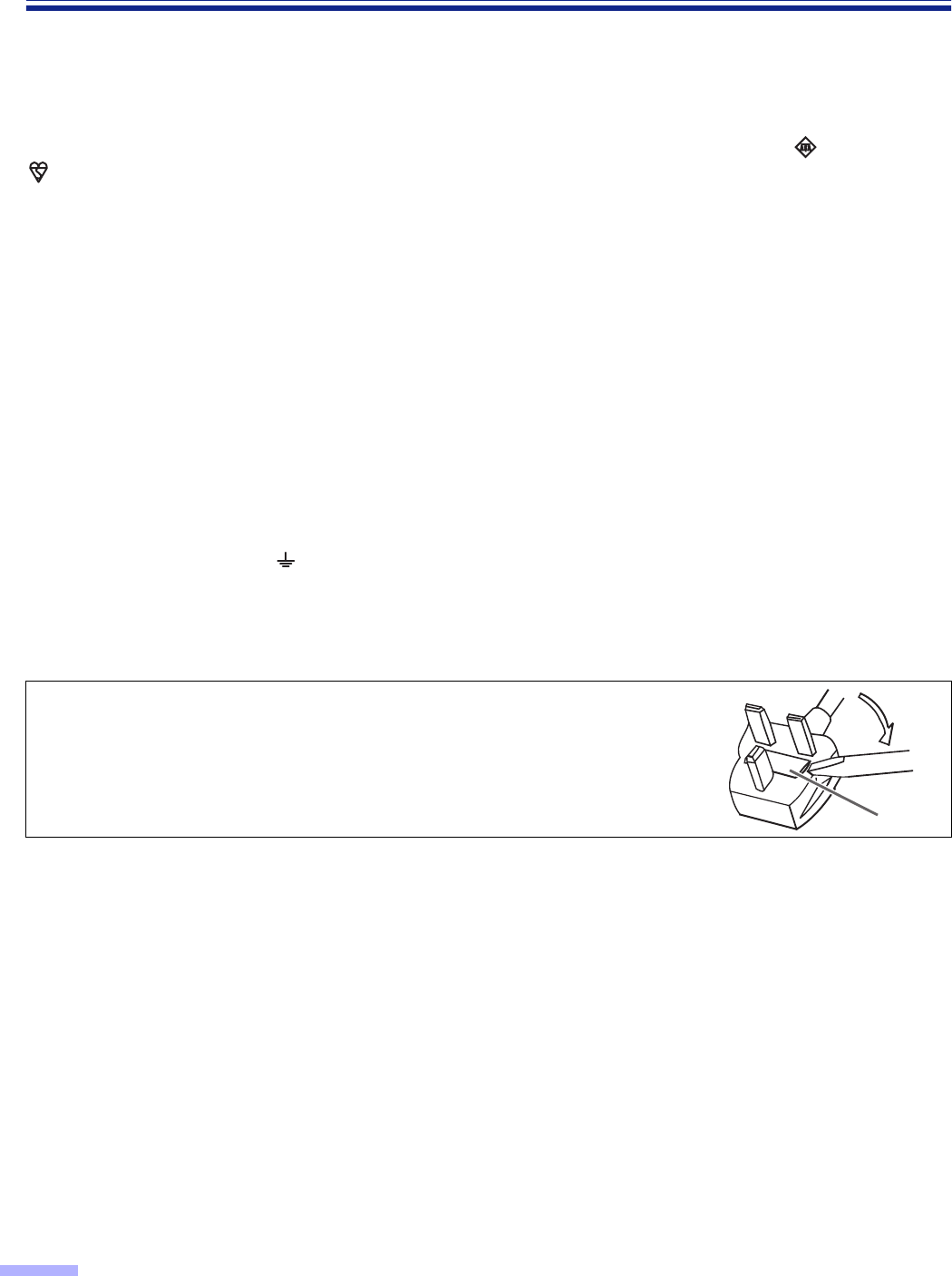
FUSE
How to replace the fuse :
Open the fuse compartment with a screwdriver and replace
the fuse.
7
Notice
English
The product should be used only with a power cord that is supplied by the manufacturer.
Français
Le produit ne devra être utilisé qu’avec le cordon d’alimentation fourni par le fabricant.
Deutsch
Dieses Gerät darf nur mit dem vom Hersteller gelieferten Netzkabel verwendet werden.
Español
Este producto deberá utilizarse solamente con el cable de alimentación suministrado por el
fabricante.
Svenska

8
Notice
For roller cleaning paper
Before using the roller cleaning paper, please read these instructions completely. Keep these instructions for future
reference.
English
WARNING
•Do not drink or inhale the roller cleaning paper fluid including isopropyl alcohol.
•The roller cleaning paper may be harmful to sensitive skin, so please use protective gloves.
•Do not use the roller cleaning paper near a heater or open flame.
•Do not store the roller cleaning paper in direct sunlight or in a place over 40 oC (104 oF).
•Only use the roller cleaning paper to clean the rollers and scanning area.
•If you need more information about the roller cleaning paper, please refer to the Material Safety Data Sheet
(MSDS).
•Please ask your Panasonic sales company about obtaining the Material Safety Data Sheet.
KEEP AWAY FROM FIRE.
Français
Avertissement
•Ne pas absorber le liquide du papier de nettoyage de rouleaux fourni ni en respirer les émanations car il contient
de l’alcool isopropylique.
•Le papier de nettoyage de rouleaux pouvant être néfaste pour les peaux sensibles, utiliser des gants de
protection.
•Ne pas utiliser le papier de nettoyage de rouleaux à proximité d’un feu ou d’une flamme vive.
•
Ne pas ranger le papier de nettoyage de rouleaux en plein soleil ni à une température dépassant 40 oC (104 oF).
•Utiliser le papier de nettoyage de rouleaux exclusivement pour le nettoyage des rouleaux et de la surface de
balayage.
•Pour tout renseignement complémentaire sur le papier de nettoyage de rouleaux, voir la feuille de données sur
la sécurité du matériel.
•Pour la feuille de données sur la sécurité du matériel, s’adresser au revendeur Panasonic.
NE PAS APPROCHER DU FEU.
Deutsch
WARNUNG
•Die Walzenreinigungspapier-Reinigungsflüssigkeit enthält Isopropylalkohol und darf auf keinen Fall getrunken
oder inhaliert werden.
•Bitte Schutzhandschuhe tragen, da das Walzenreinigungspapier bei empfindlicher Haut Reizungen verursachen
kann.
•Das Walzenreinigungspapier nicht in der Nähe von Heizgeräten oder offenen Flammen verwenden.
•Das Walzenreinigungspapier nicht in direkter Sonneneinstrahlung oder an Orten lagern, an denen Temperaturen
von mehr als 40
oC
erreicht werden.
•Zum Reinigen der Walzen und des Scanbereichs ausschließlich das Walzenreinigungspapier verwenden.
•Weitere Informationen zum Walzenreinigungspapier sind dem Materialsicherheits-Datenblatt zu entnehmen.
•Das Materialsicherheits-Datenblatt ist auf Wunsch von Ihrem Panasonic-Fachhändler erhältlich.
VON FEUER FERNHALTEN!
9
Notice
Español
ADVERTENCIA
•No beba el líquido del papel de limpieza de rodillos ni aspire las emanaciones del alcohol isopropílico que
contiene.
•El papel de limpieza de rodillos puede ser perjudicial para las pieles sensibles, así que póngase guantes de
protección.
•No utilice el papel de limpieza de rodillos cerca de una calefacción o una llama.
•No guarde el papel de limpieza de rodillos expuesto a la luz solar directa ni en un lugar donde la temperatura
sea superior a 40 °C.
•Utilice solamente papel de limpieza de rodillos para limpiar los rodillos y el área de escaneado.
•Si necesita más información acerca del papel de limpieza de rodillos, consulte la hoja de datos de seguridad del
material (MSDS).
•Pregunte a la compañía de ventas Panasonic cómo obtener la hoja de datos de seguridad del material.
MANTÉNGALO ALEJADO DEL FUEGO.
10
Precautions
The following precautions are recommended to extend the life of the unit.
≥≥
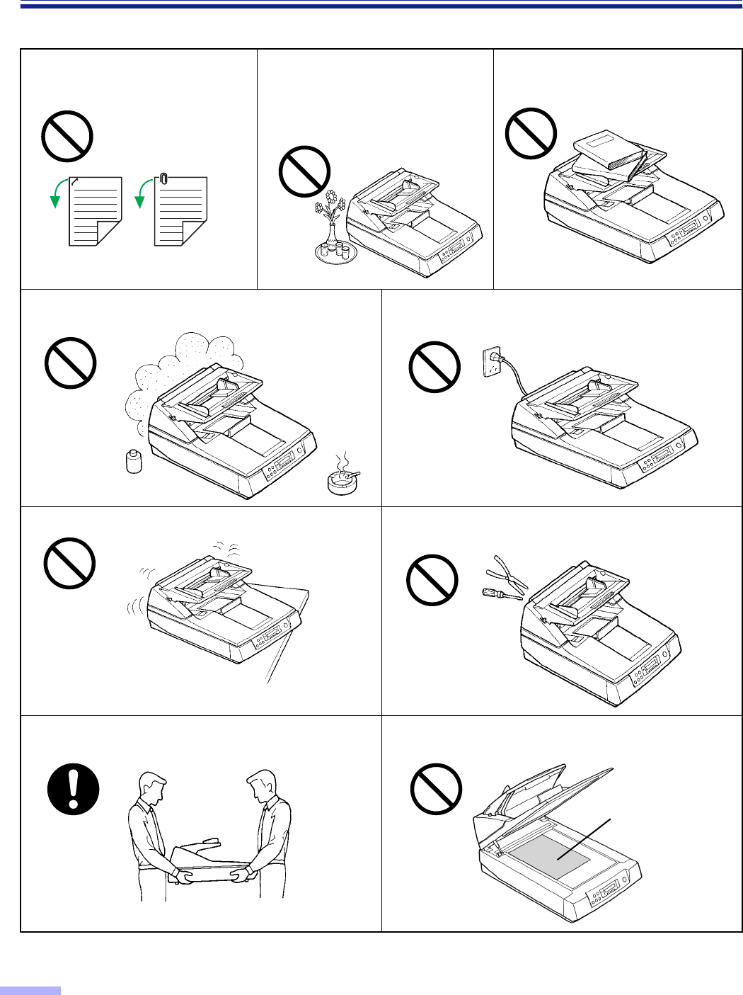
≥≥Special care should be taken to protect the unit if it is used in a less than optimum environment, such as a dusty or
sandy area.
Do not place the unit in an area where there is a lot of
smoke, dust, chemical fumes or vibration. Do not leave the power cord plugged into the AC outlet
if the unit is not used for an extended period.
Do not place the unit on an uneven or unstable surface. Do not disassemble the unit.
This will void your warranty.
It is recommended that if the scanner has to be moved,
at least two people carry it. For safety reason, do not look directly at the light.
(You may damage your eyes.)
EX
Document
Do not place books, paper, or other
items on the unit.
Do not place any liquids near the unit.
— Accidental spillage of liquid into the
unit may cause severe damage. If
this occurs, turn the unit off, unplug
the power cord and call for service.
Prior to scanning, remove, all
staples and paper clips from pages.
11
Precautions
Operating Environment
≥≥
≥≥Power Source
•Use a voltage level that does not vary more than ±10 % from the voltage level marked on the nameplate
(located on the back side of the scanner ).
•Do not use an extension cord.
•This scanner should be connected to a grounded outlet.
•Do not use a line conditioner, transient suppressor or surge protector.
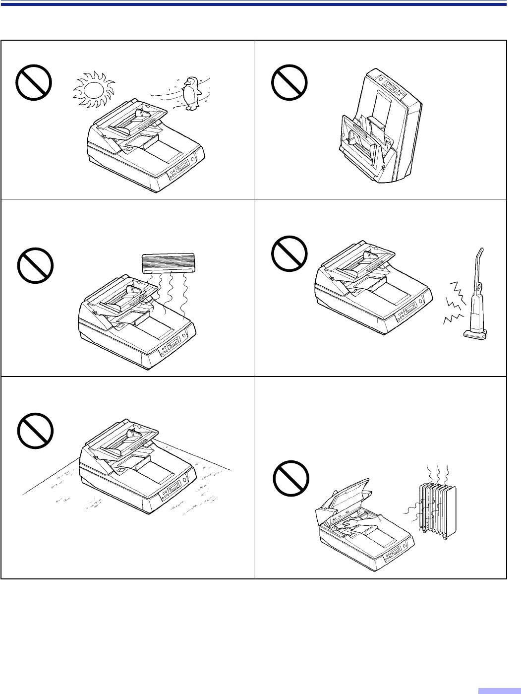
Do not place the unit in direct sunlight or in a cold draft. Do not operate or place the unit in a vertical position.
Do not place the unit near a heating appliance or an air
conditioning vent. Do not place the unit in a room with
extremely high or low humidity.
Do not place the unit near other appliances which
generate large electrical noise.
Do not place the unit on a carpet. (Static electricity can
cause the unit to malfunction.) Do not drink or inhale the included roller cleaning paper
fluid.
The roller cleaning paper may be harmful to sensitive
skin, so please use protective gloves.
Do not use the roller cleaning paper near a heater or
open flame. This may cause a fire.
12
Precautions
∫∫
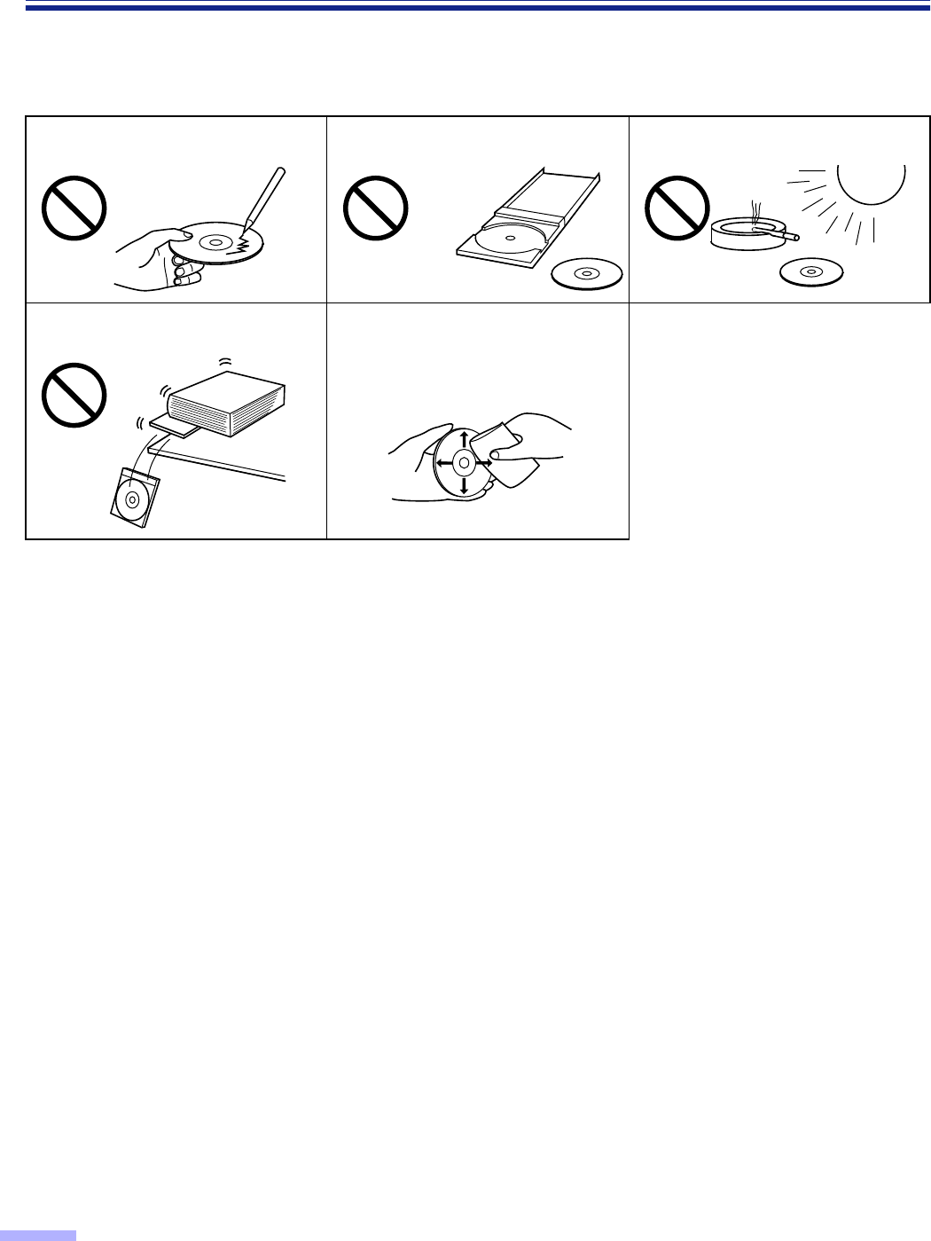
∫∫CD-ROM
To prevent the CD-ROMs from accidental damages:
Do not touch or write on the surface
of the disc. Do not leave the disc out of the
protective case. Do not leave the disc in direct
sunlight or near heat sources.
Do not place heavy objects on the
disc case or drop the case. To clean the disc, hold the disc by
its edges and wipe it from the
center to the edges with a dry, soft
cloth.
13
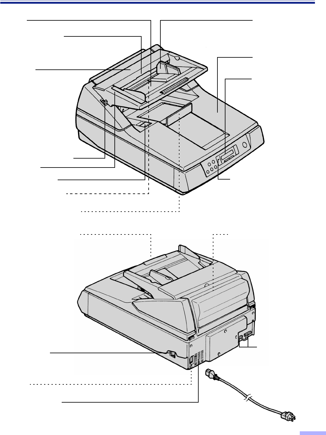
Component Identification
Hopper
ADF door release
Inside the ADF door.
ADF door
Manual feed selector
Front door
Exit substopper
Document guide
Display panel
When performing
each setting, used to
display the scanning
conditions, etc.
Power indicator
When the power is turned on,
the green indicator lights.
When an error occurs, the
indicator will change to red,
and light steadily or flash.
Front door release
Inside the front door.
Exit document stopper
Document cover
AC inlet
Fan exhaust vent
Imprinter door
(Top door)
Used for attaching the
imprinter unit and ink
Power switch
[ : on position
≤: off position
Hopper extension tray
Connectors
Used to connect the
scanner unit to a
host computer.
Power cord
Component Identification
14
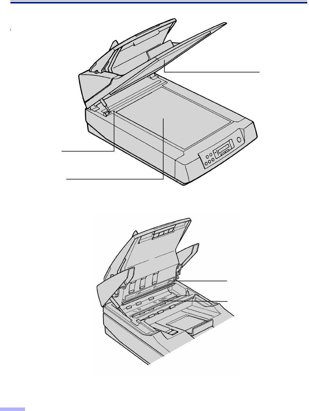
Component Identification
Standard mark
Document glass
Cover sheet
(black sheet)
CIS glass
(For KV-S6055W series only)
Scanning section glass
15
Display Panel Instructions
The required settings must be selected prior to scanning.
Information and conditions are shown on the LCD (Liquid Crystal Display).
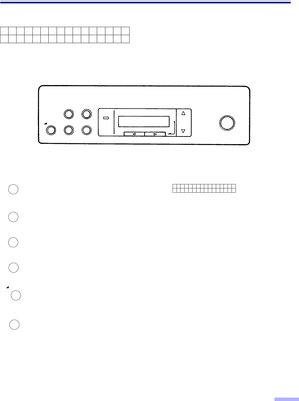
∫∫
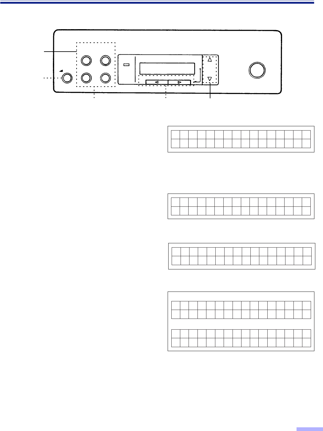
∫∫Display panel and keys
Ready
: Press to enter the scanning setting menu.
Up to 32 characters can be displayed
during scanning or setting.
: Press to enter the counter setting menu.
: Press to enter the imprinter setting menu. 3: Press to advance to the next mode in the
selected menu.
: Press to enter “others” setting menu. 4: Press to return to the previous mode in
the selected menu.
: Press to exit from the setting section and
return to the ready status.
Also, this function can change the display
language.
1: Press to advance to the next value in the
selected mode.
: Press to start or stop scanning a document
or batch of documents. 2: Press to return to the previous value in
the selected mode.
SCAN COUNTER
IMPRINT OTHERS READY/
ERROR
STOP/START
MODE
SELECT
HOME
SCAN
LCD :
COUNTER
IMPRINT
OTHERS
HOME
STOP / START
16
Display Panel Instructions
∫∫
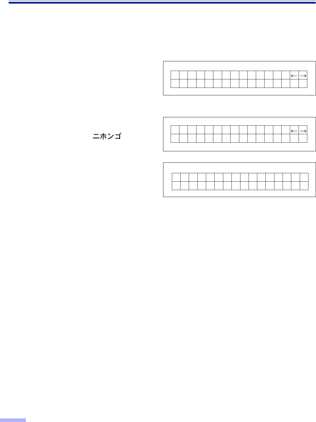
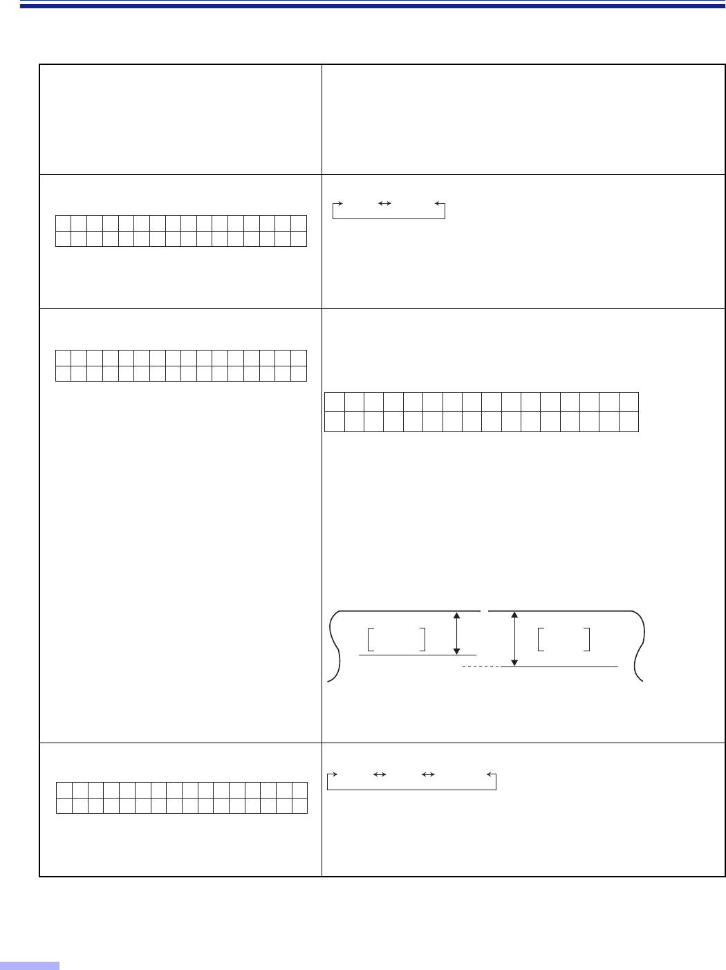
∫∫Setting the language
•Select English, German or Japanese as the language which is to appear on the LCD display.
•The language setting mode is appeared automatically when the unit’s power is turned on for the first time after
the unit was purchased. English is the default language.
1
Turn the power on while pressing
the HOME key.
•When “High Speed Scanner” or other
words appear on the LCD, release the
HOME key.
2
Use the 2 key or the 1 key to select
“English Letter”, “English A4”,
“Deutsch A4” or “ A4”.
3
Press the HOME key.
•The display will change to the selected
language, then the scanner will be ready.
•This setting will remain until it is changed
to another setting.
Se t Lang ua ge
Eng l i sh Let ter
D e u t s c h A 4
Se t Lang ua ge
Berei t

17
Display Panel Instructions
∫∫
∫∫Setting the scanner
The following parameters can be customized using the scanner’s various setting modes. If the application
software provides these features, it will be supported by the scanner.
Scan menu
No. Item LCD Content Page
01 Front side brightness F. Brightness Selection for density when scanning the front
side of a document.
2202
Front side image emphasis
F. Emphasis Selection for emphasis when scanning the
front side of a document.
03 Front side contrast F. Contrast Selection for contrast when scanning the front
side of a document.
04 Front side halftone F. Halftone Selection for gradation when scanning the
front side of a document.
23
05 Back side dropout color
(For KV-S6055W series only) B. Color drop Color selection for dropout when scanning
the back side of a document.
06 Back side brightness
(For KV-S6055W series only) B. Brightness Selection for density when scanning the back
side of a document.
07 Back side image emphasis
(For KV-S6055W series only) B. Emphasis Selection for emphasis when scanning the
back side of a document.
08 Back side contrast
(For KV-S6055W series only) B. Contrast Selection for contrast when scanning the
back side of a document.
09 Back side halftone
(For KV-S6055W series only) B. Halftone Selection for gradation when scanning the
back side of a document.
24
10 Noise reduction Noise Reduct. Selection for noise reduction when scanning
a document.
11 Black line removal BLK Line
Remove
Selection to choose the black lines which
appear at the top, bottom and left/right sides
of the image after scanning the document.
12 Scanning mode Scanning
Mode Selects whether documents are scanned at
actual size or reduced (Fit to page) size.
13 Double feed detection Double Feed
Selection to choose to detect double feeding
function.
When scanning very important documents,
confirm if the number of scanned pages
displayed on the LCD matches the number of
actual pages.
14 Setting the “Double Feed”
detector action Double Feed
Action Selects the action of the Double Feed
Detector when double feed occurs. 25
15 Setting the “Double Feed”
detector sensitivity Double Feed Selects the sensitivity of the Double Feed
Detector.

18
Display Panel Instructions
Scan menu
No. Item LCD Content Page
16 Feed speed Feed Speed Selection for feed speed when a document is
being scanned. 25
17 Setting the “Detect Skew” Detect Skew Selects whether skew is detected or not
detected.
18 Scanning method Scan Method
Selection of documents to be scanned.
This includes documents placed in the ADF
and documents placed on the flatbed glass
(document glass).
2619
Save scanning settings
(Select memory) Save Setting Selects the memory where the conditions are
saved into.
Save scanning settings
(Execution) Save Setting Saves the scanning conditions into the
memory. (2 memory settings)
20 Load scanning setting Load Setting
Loads the memory where the scanning
conditions have already been saved. If
“Default” is selected, all of the scanning
conditions will return to the default values.

19
Display Panel Instructions
Counter menu
Imprinter menu
Depending on the setting on the “Counter setting menu”, the page number of the scanned document will be
printed. The imprint unit (KV-SS010) is required. If a host computer is connected, there may be settings required
on the host computer as well.
No. Item LCD Content Page
01 Select the counter
displayed on the
LCD. Disp. Counter Selection to choose to display the cleared counter
(scan counter) after scanning one time or to display the
user set counter (user counter) on the LCD.
27
02
Setting the User
Counter User Counter Selection for default number before scanning
Setting the user
counter extender User Counter Selection for an increase in the default number
Clear the user
counter. User Counter Clears the counter which was set by the user.
03 System Count System Count. Displays the total amount of scanned documents up to
now.
No. Item LCD Content Page
01 Setting the
imprinter data Pre Imprint
Allows for the selection of the printing content using an
imprinter.
The imprinter will print on the printing (front) side of the
document scanned.
28
02 Setting the
imprinter position Pre Position Allows for the selection of the printing position using an
imprinter.
03 Setting the
imprinter font style Pre Font Alows for the selection of the printing font style using
an imprinter.
04 Setting the
imprinter
orientation Pre Rotate Allows for the selection of the printing orientation using
an imprinter. 29

20
Display Panel Instructions
Others menu
No. Item LCD Content Page
01 Checking the version Version
Displays the firmware version of the mechanical
control, pre-imprinter or post-imprinter.
If an optional imprinter is not installed, the imprinter
version will not be displayed.
30
02 Setting the buzzer Buzzer
Selects whether the buzzer is turned on or off.
If selection is in the “ON” position:
When pressing a key, one short beep will be heard.
When there is an error, 5 short beep will be heard.
When scanning is completed correctly, one long beep
will be heard.
03 Setting the SCSI ID SCSI ID Sets the SCSI ID No.
04 Setting the terminator Terminator Set “Enable” or “Disable”.
“Enable”: If last device on chain
“Disable”: If between devices
05 Setting the transfer
rate Transfer Rate
•Changes the maximum value of the synchronous
transfer rate of the SCSI interface.
•Lower the synchronous transfer rate to 10 Mbytes/
sec. if the computer has failed to recognize the
scanner or the scanner fails to operate properly.
06
Checking the roller
cleaning warning Clean Roller The alarm tells you it is time to check roller.
If it is near 100%, clean the roller. See “Cleaning the
Unit” on page 44.
31
Clearing the roller
cleaning warning Clean Roller Clear the “Clean Roller Warning ≤≤%” display.
07
Checking the roller
modules replacement
warning Replace Roll.
The alarm tells you the roller needs to be changed.
If it is near 100%, replace the paper feed roller module
and retard roller module. See “Replacing Consumable”
on page 52.
Clearing the roller
modules replacement
warning Replace Roll. Clear the “Replace Roll. Warning ≤≤%” display.
08 Setting the product ID Product ID
Selects the product ID. The product ID setting depends
on the host computer scanner application you are
using.
Allows scanner to emulate other Panasonic scanner. 32
09 Setting the sleep
mode Sleep Mode Sets the time until sleep mode turns ON.
21
Display Panel Instructions
¥Operation
1
Press the menu key until the desired
menu is displayed.
•The SCAN, COUNTER, IMPRINT and
OTHERS keys are used as a menu key.
•When pressing the SCAN key, the display
will appear as shown in the diagram on
the right.
2
Use the
3
key or the
4
key to select
the desired item.
•The display at the right is an example of a
setting for the scanning setting mode.
3
Use the
1
key or the
2
key to select
the desired content.
•The display on the right is an example of
a setting for the back side contrast.
4
Press the HOME key to return to the
“Ready” display or another menu key
to go to another menu.
§In steps 2 or 3, you can change to the desired menu by pressing the desired menu key.
§See pages 22 to 33 for details.
§For changing the display language, see page 16.
SCAN COUNTER
IMPRINT OTHERS READY/
ERROR
STOP/START
MODE
SELECT
HOME
1,4
4
32
Menu keys
0 1 . F . B r i g h t n e s s
D––––+––––L Hos t
07.B.Contrast
L––––+––––H Hos t
07.B.Contrast
L––✽–+––––H L2
Ready
01.Di sp.Counter
Scan
When the HOME key is pressed :
When the COUNTER key is pressed for another menu key :
(ex. SCAN)
22
Display Panel Instructions
¥Actual settings
Scan setting menu (by pressing the SCAN key)
•For changing the display language, see page 16.
Number, mode and default display
•Pressing the
3
key will change to the next
mode.
•Pressing the
4
key will change to the
previous mode.
Contents
•Pressing the
1
key or the
2
key will change to another
value.
01 Front side brightness
•When “Host” is displayed, pressing the
1
key or the
2
key
will change the display to “Norm”.
•“D” means dark. “L” means light.
02 Front side image emphasis
•When “Host” is displayed, pressing the
1
key or the
2
key
will change the display to “Medium”.
03 Front side contrast
•When “Host” is displayed, pressing the
1
key or the
2
key
will change the display to “Norm”.
•“H” means high. “L” means low.
01.F.Br ightness
Dssssrssss LHos t
D4 D2D3 D1 Norm
Host
L4L3L2L1
02.F.Emp
sssrs Hos t
hasis NoneSmooth Low Medium
Host
High
03.F.Contrast
LssssrssssHHos t
L4 L2L3 L1 Norm
Host
H4H3H2H1
23
Display Panel Instructions
04 Front side halftone
§1The dynamic threshold is not displayed if the DIMM
expansion memory module has not been installed. If the
dynamic threshold is to be used, install a DIMM memory
module which is available on the market. For details on
how to install it refer to the installation manual.
05 Back side dropout color
•KV-S6055W series only.
Color selection
06 Back side brightness
•KV-S6055W series only. •When “Host” is displayed, pressing the 1 key or the 2 key
will change the display to “Norm”.
•“D” means dark. “L” means light.
07 Back side image emphasis
•KV-S6055W series only. •When “Host” is displayed, pressing the 1 key or the 2 key
will change the display to “Medium”.
08 Back side contrast
•KV-S6055W series only. •When “Host” is displayed, pressing the 1 key or the 2 key
will change the display to “Norm”.
•“H” means high. “L” means low.
04.F.Hal
Hos t
f tone BinaryHost Bayer dither 64 Bayer dither 16
(Dynamic Th.)
Halftone dot 32 Error diffusionHalftone dot 64
§1
05.B.Col
Hos t
or drop
GreenRedHost
06.B.Br ightness
Dssssrssss LHos t
D4 D2D3 D1 Norm
Host
L4L3L2L1
07.B.Emp
sssrs Hos t
hasis NoneSmooth Low Medium
Host
High
08.B.Contrast
LssssrssssHHos t
L4 L2L3 L1 Norm
Host
H4H3H2H1
24
Display Panel Instructions
09 Back side halftone
•KV-S6055W series only.
§1The dynamic threshold is not displayed if the DIMM
expansion memory module has not been installed. If the
dynamic threshold is to be used, install a DIMM memory
module which is available on the market. For details on how
to install it refer to the installation manual.
10 Noise reduction
B1
a
1TB6
a
6 : Scanner reduces a black dot.
W1
a
1TW6
a
6 : Scanner reduces a white dot.
11 Black line removal
•This setting is valid only when the white roller kit is installed.
12 Scanning mode
Fit to Page :
Actual :
Scanner shrinks image to fit scanned page.
Scanner scans at 100% actual page size.
Some of the data on the edges of the page may be
lost.
13 Double feed detection
If set to “Detect”, the scanner will sound a buzzer and the power
indicator will flash red when double feeding is detected. Even if
this buzzer is set to “OFF” in “Setting the buzzer” (see page 30),
it will still ring.
•When scanning very important documents, confirm if the
number of scanned pages displayed on the LCD matches the
number of actual pages.
09.B.Hal
Hos t
f tone BinaryHost Bayer dither 64 Bayer dither 16
(Dynamic Th.)
Halftone dot 32 Error diffusionHalftone dot 64
§1
10.No i se Reduc t .
rssssss Hos t
NoneHost B1✕1 B2✕2B3✕3
B4✕4B5✕5B6✕6W1✕1W2✕2
W3✕3W4✕4W5✕5W6✕6
11 . BLK L
Remove Hos t
ine DisableHost Enable
12.Scan
Hos t
ning
Mode Fit to PageHost Actual
13.Doub l
Hos t
e Feed Not detectHost Detect
25
Display Panel Instructions
•When scanning very important documents, confirm if the number of scanned pages displayed on the LCD
matches the number of actual pages.
•Thick, creased, or edited documents with correction fluid as well as documents with holes near the center may
give you false double feed warning.
•When scanning a document which is shorter than 210 mm/8.3" (A5 size) in length, double feed detection will
not work well.
14 Setting the “Double Feed” detector
action
Host : The scanner will act in response to commands from
the host computer.
Stop : The scanner will display double feed error and stop
when it detects double feeding.
Buzzer : When the scanner detects double feeding, it will
sound a buzzer, the power indicator will light red and
it will continue scanning.
After completing scanning, the scanner will display
double feeding warning.
15 Setting the “Double Feed” detector
sensitivity
Low sensitivity : The double feed detector’s sensitivity will be
low. Set this when there is an error for no
double feeding.
High sensitivity : The double feed detector’s sensitivity will be
high. Set this when there is no error for
double feeding.
16 Feed speed
Fast : The scanner scans approximately 1.3 times faster
than when “Normal” is set, at a resolution ranging
from 200dpi to 400dpi. For example, when the
resolution is 200dpi, the scanner scans at 200dpi
a
150dpi, but outputs the image at 200dpi
a
200dpi.
However, the image quality produced by “Fast” is
inferior to the image quality produced by “Normal”.
Slow : The scanner scans at half of the “Normal” speed.
17 Setting the “Detect Skew”
Detect : If the document is not moving straight, scanning
will stop and “U20 Skew Error” will be displayed.
Not detect : The document will be scanned even if it is not
moving straight.
14.Doub l
Ac t i on Hos t
e Feed
StopHost Buzzer
15.Doub l
H o s t
e Feed
S e n s .
Low sensitivitySens. Host
Normal Sens. High sensitivity
16.Feed
Hos t
Speed SlowHost Normal Fast
17.Detec t
Hos t
Skew Not detectHost Detect
26
Display Panel Instructions
•
Scanning settings 01-18 must be saved using setting “19 Save Scanning Settings (Execution)”.
Even if they are not saved, they will be applied. If the power is turned off, the next time the unit is used they will
not be applied.
18 Scanning method
Host : The documents placed either on the ADF or on the
flatbed are scanned in response to commands from
the host computer.
FB : The documents placed on the flatbed are scanned.
19 Save “Scanning Settings”
(Select memory)
19 Save “Scanning Settings”
(Execution)
When pressing the
1
key and the
2
key simultaneously, the
scanning conditions set in 01 to 18 above will be saved in the
memory selected in the “Save Scanning Settings (Select
memory)”.
“Completed” will be displayed after saving.
20 Load scanning setting
•
If you use the
1
key or the
2
key to select Memory 1 or
Memory 2, the saved scanning items will become valid by
the “Save Scanning Settings (Execution)”.
If other scanning items have been saved in another memory,
during scanning you can change the scanning items easily.
This setting will not be changed even if the power is turned
off and on, and will remain valid.
•
If “Default” is selected, all of the saved scanning settings will
return to the default values. (See “01” to “18” of the left side
display.)
18.Scan
Hos t
Metho d FBHost
19.Save Se t t i ng
Memo r y 1
Memory 1 Memory 2
19.Save
Execl
Se t t i ng
20.Load
Defaul t
Se t t i ng Memory 1 Memory 2
Default
27
Display Panel Instructions
Counter setting menu (by pressing the COUNTER key)
Number, mode and default display
•
Pressing the
3
key will change to the
next mode.
•
Pressing the
4
key will change to the
previous mode.
Contents
•
Pressing the
1
key or the
2
key will change to another value.
01
Select the counter displayed on the
LCD
Scan : After scanning one time, the scanner counter will be
cleared.
User : This counter is set to the default value.
The user counter extender is also set by the user.
They will be cleared when the power is turned OFF.
02 Setting the user counter
Pressing the
1
key once will increase the user counter by one.
Pressing the
2
key once will decrease the user counter by one.
Pressing the
1
key or the
2
key continuously will change the
user counter value by increments of 10.
02 Setting the “User Counter
Extender”
Pressing the
1
key once will increase the user counter extender
by one. Pressing the
2
key once will decrease the user counter
extender by one.
02 Clear the “User Counter”
When pressing the
1
key and the
2
key simultaneously, the
user counter will be cleared.
Then “Completed” will be displayed.
03 Displaying the system counter
(ex.)
Displays the total amount of scanned documents up to now.
01.Di sp.
Scan
Counter
UserScan
02.User
0
Counter
02.User
+1
Counter
r2r1r3...... r8r7r9
02.User
Clearl
Counter
03.Sys t e
1234567
m Coun t .
28
Display Panel Instructions
Imprinter setting menu (by pressing the IMPRINT key)
These setting can be done only when a imprinter unit is installed.
.
Number, item and default display
•
Pressing the
3
key will change to the
next mode.
•
Pressing the
4
key will change to the
previous mode.
Contents
•
Pressing the
1
key or the
2
key will change to another
value.
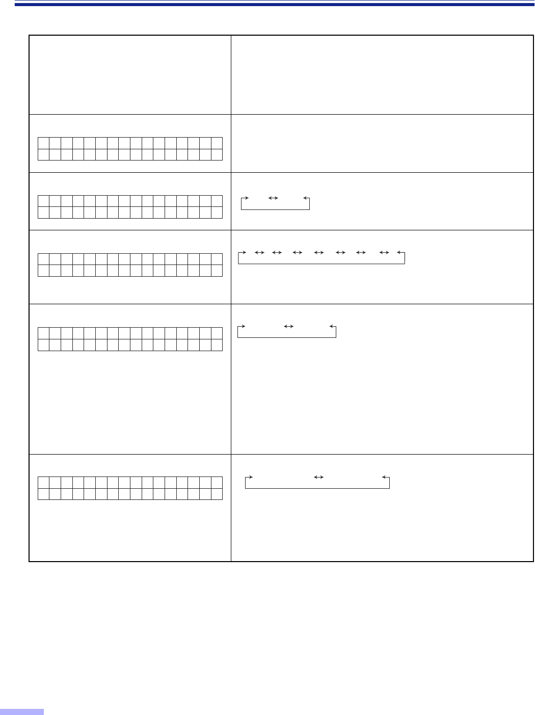
01 Setting the imprinter data
•
This setting can be done only when a
imprinter is installed.
Host : Printing will be done according to the host computer.
Count : Printing will be done according to the counter in the
“Select the counter displayed on the LCD”.
02 Setting the imprinter position
•
This setting can be done only when a
imprinter is installed.
By pressing the
1
key or the
2
key, you can specify the line
where printing starts from the top of the document.
If “0” character is set, printing starts from 10.0 mm.
The millimeter value displayed is an approximation.
The length per character varies, depending on the 04
orientation setting.
90°or 270°: 2.40mm per character
0°or 180°: 3.46mm per character
Character: 0 - 72
•
In this example, printing starts at 12.4 mm (approx, 1/2 in.)
from the top of the paper. The number 12.4 can be changed
from 10.0 to 182.8 by pressing the
1
key or the
2
key.
03 Setting the imprinter font style
•
This setting can be done only when a
imprinter is installed.
Bold :
2-dot font
Normal: 1-dot font that can increase the ink lifetime longer than
Bold fonts
01.Pre I
Hos t
mp r i n t
CountHost
02.Pre P
H
osition
ost
02.Pre Position
< 1Cha r > 12.4mm
Top of the paper Top of the paper
Top of the
printout
ABCD ......
ABCD ......
Top of the
printout
10mm (Default) 12.4mm
Approx.
1/2 in.
Approx.
13/32 in.
03.Pre F
Hos t
ont
NormalBoldHost

29
Display Panel Instructions
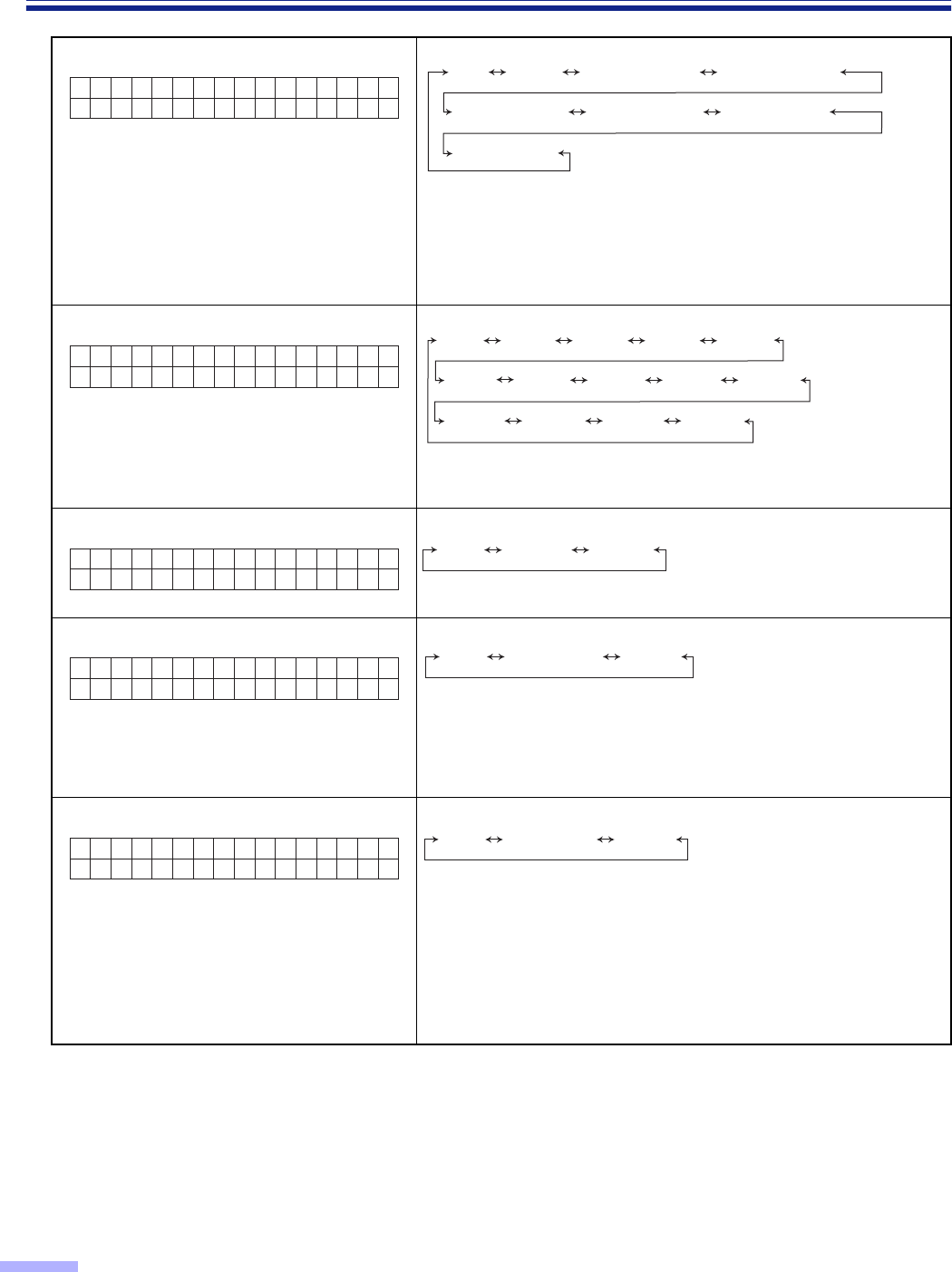
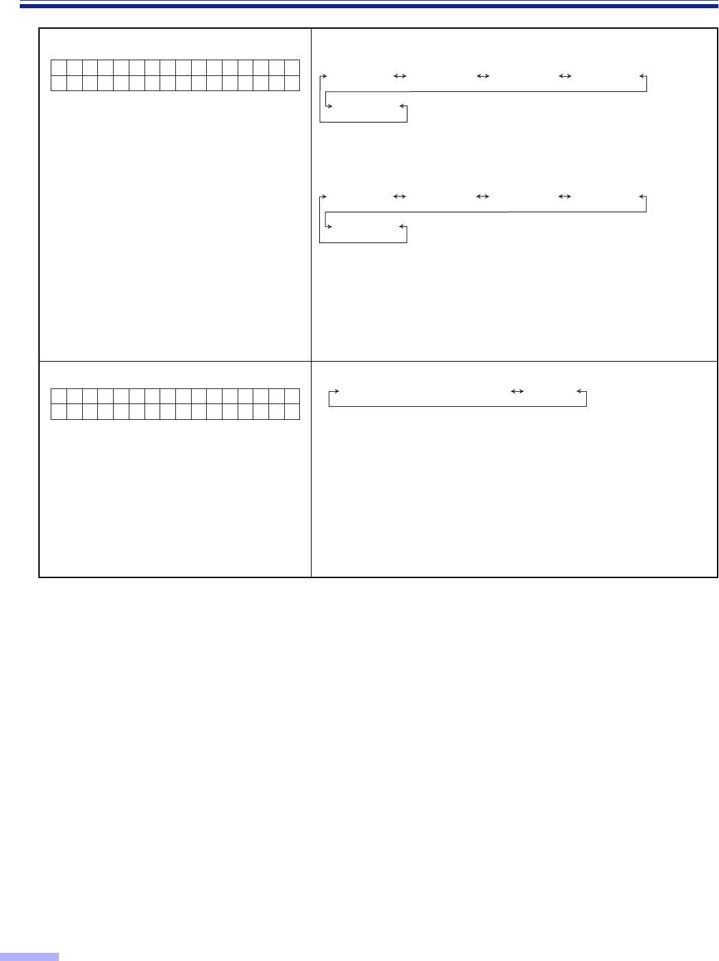
04 Setting the imprinter orientation
•This setting can be done only when an
imprinter is installed.
04.Pre R
Hos t
otate Host 0o90o180o270o
A
B
A
B
AB
AB
:Transfer direction
Prints portrait orientation.
Rotates character string 90 degrees and prints.
Prints portrait orientation from the end of
the character string.
Rotates character string 270 degrees and prints.
0x
90x
180x
270x
30
Display Panel Instructions
“Others”setting menu (by pressing the OTHERS key)
Number, mode and default display
•Pressing the
3
key will change to the
next mode.
•Pressing the
4
key will change to the
previous mode.
Contents
•Pressing the
1
key or the
2
key will change to another value.
01 Checking the Version MX.XX : Displays the mechanical control firmware version.
FX.XX : Displays the imprinter firmware version.
If an imprinter unit is not installed, the firmware version
will not be displayed.
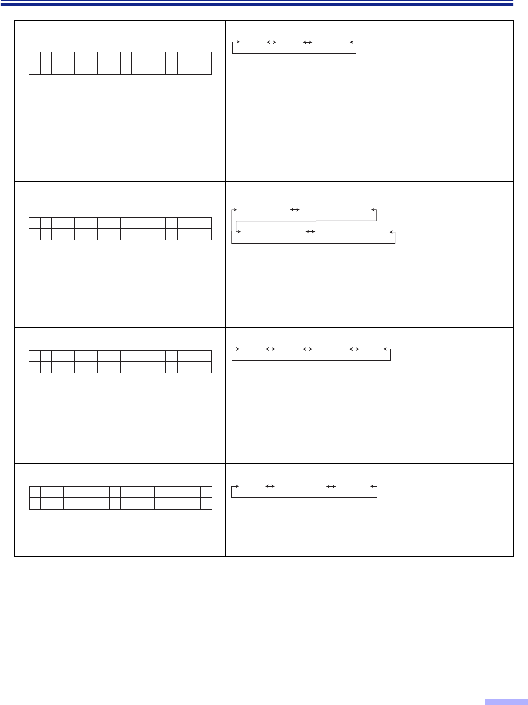
02 Setting the “Buzzer”
03 Setting the SCSI ID
•Setting the SCSI ID will be activated after turning the power off
and turning it on again.
04 Setting the “Terminator”
When the scanner is located to terminal position on SCSI bus,
set to “Enable”.
•Setting the terminator will be activated after turning the power
off and turning it on again.
•The internal terminator works only when the units power has
been turned on. If the PC is to be used while the unit’s power is
off, be absolutely sure to install an external terminator which is
available on the market.
05 Setting the transfer rate
•Changes the maximum value of the synchronous transfer rate
of the SCSI interface.
•Lower the synchronous transfer rate to 10 Mbytes/sec. if the
computer has failed to recognize the scanner or the scanner
fails to operate properly.
01.Ver s i
MX .XXFX.XX
on
02.Buzze
ON
rOFFON
03 . SCS I
No.6
ID 21 3 5467
0
04.Termi
E n a b l e
nator Disable Enable
05.Transfer Rate
20MBy t e/sec
20MByte/sec 10MByte/sec
31
Display Panel Instructions
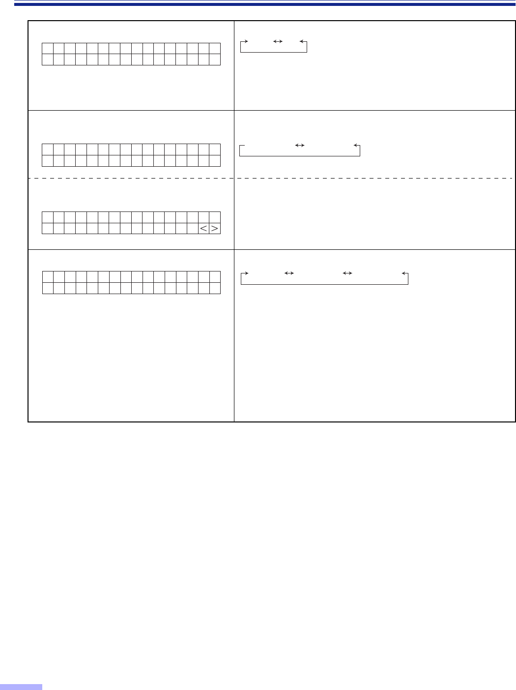
06 Checking the “Roller Cleaning
Warning”
0% : This is displayed when “Clean Roller Warning ≤≤%”
displayed is cleared.
100% : This is displayed when the roller needs to be cleaned.
06 Clearing the “Roller Cleaning
Warning”
When pressing the
1
key and the
2
key simultaneously,
“Clean Roller Warning” will be cleared. Then “Completed” will be
displayed.
07 Checking the roller modules
replacement warning 0% : This is displayed when “Replace Roll. Warning ≤≤%”
displayed is cleared.
100% : This is displayed when the roller modules need to be
replaced.
07 Clearing the roller modules
replacement warning When pressing the
1
key and the
2
key simultaneously,
“Replace Roll. Warning” will be cleared. Then “Completed” will
be displayed.
06.Cl ean
Warning Ro l l e r
0 %
06.Cl ean
Warning Ro l l e r
Cl ear=<>
07.Rep l a
Warning 0%
ce Ro l l .
07.Rep l a
Warning Clear=<>
ce Ro l l .
32
Display Panel Instructions
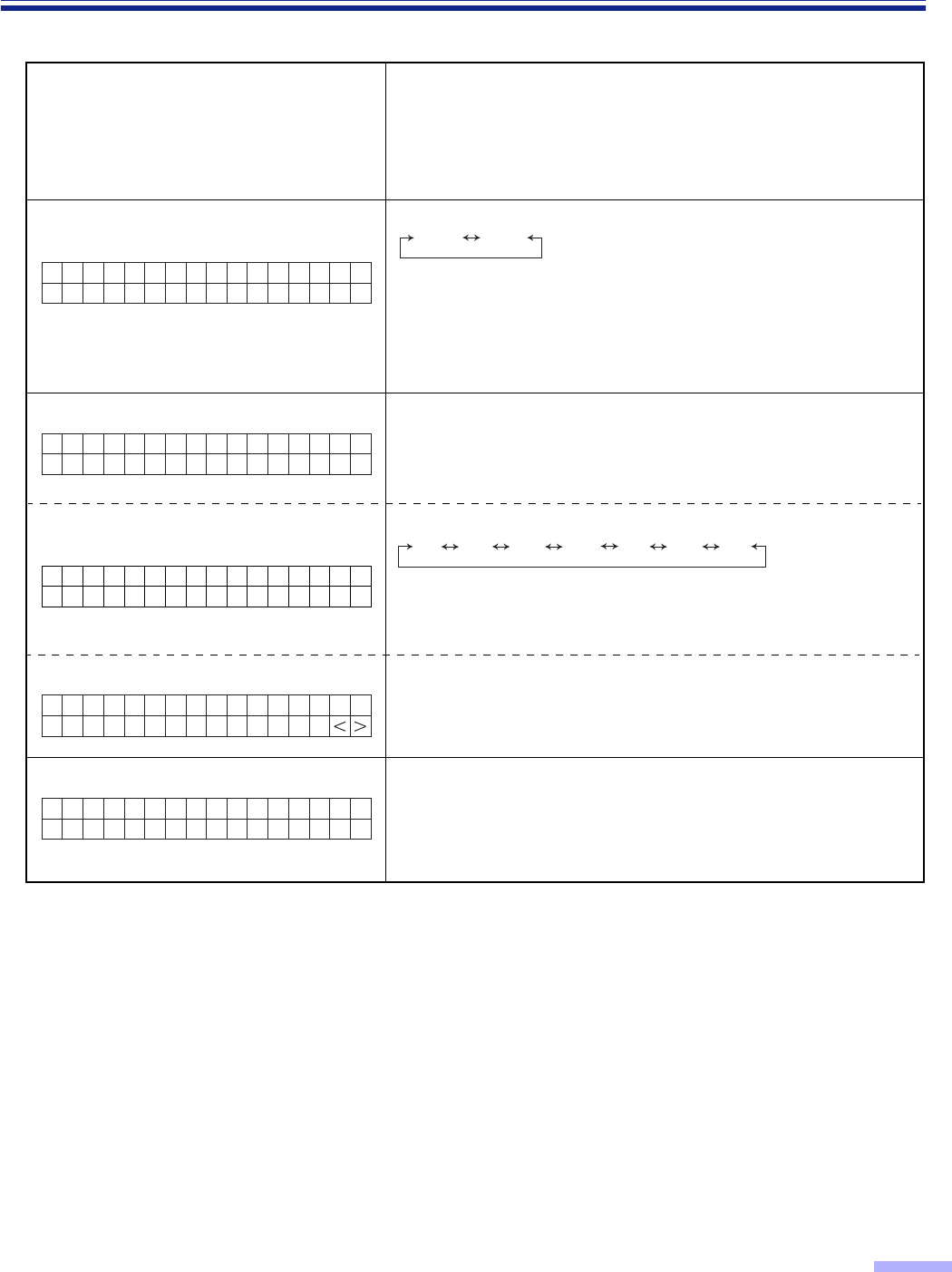
08 Setting the “Product ID” •KV-S6055W series
•KV-S6050W series
The applications for the scanner which have been set can be
used.
•An error results if an attempt is made to use a function which
are not provided with the KV-S6050W or KV-S6055W series of
scanners.
•No guarantees are given for complete compatibility.
09 Setting the sleep mode
To conserve energy and operating cost,
this scanner is provided with a
programmable power save feature. The
scanner is factory set with the power save
feature (sleep mode) turned on to comply
with ENERGY STAR® requirement. If sleep
mode is enabled, the scanner enters the
sleep mode when the scanner is idle for
15 minutes.
•1min. T 60min.
•To return from the sleep mode, press any key on the scanner or
issue the scan instruction from the application.
08.Produ
KV-S6055
ct ID KV-S6055 KV-SS855 KV-S2055 KV-S6045
KV-S2065
KV-S6050 KV-SS855 KV-S2055 KV-S6040
KV-S2065
09.Sl eep
Af ter 15min.
Mode DisableAfter 1 min. T After 60 min.
33
Display Panel Instructions
¥Other display explanations
Display Content
This will be displayed when scanning is started until it is
completed.
After completion, “Ready” will be displayed.
If the STOP key is pressed, scanning will stop. This will be
displayed when the STOP key is pressed during scanning.
Even if the STOP key is pressed in a setting mode, this will be
displayed. Then the scanner will return to setting mode after
stopping scanner operation.
This will be displayed when the STOP key is pressed and the
scanner stops.
Even if the document remains in the scanner, “JAM” will not be
displayed.
If the document remains in the scanner, open the ADF door
and the front door, then remove it.
Then “Ready” will be displayed.
This will be displayed after setting scanning to start with a host
computer.
If the document is set and the START key is pressed, scanning
will start.
This is displayed in the sleep mode.
To return from the sleep mode, press any key on the scanner
or issue the scan instruction from the application.
Scanning...
1
Stopping...Wait!
Scanner St opped
123456
Press START Key
Sl eep
34
Loading Documents on the ADF
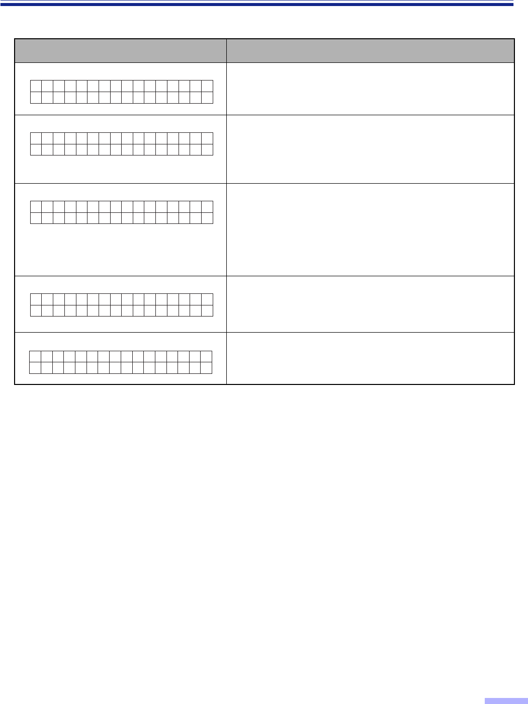
1
To prevent double feeding, separate
any documents which have been
stapled together or stacked, as in a file,
before setting in the scanner.
1Fan the stack of documents to
separate all of the edges.
2Hold both ends of the document and
bend them as shown to the right.
3To separate the document apart,
grasp them firmly and pull them so
that the center part waves as shown
to the right.
Repeat the steps above as necessary.
2
Carefully align the top left ends of the
documents.
3
Adjust the document guide slightly
larger than the actual size of the
document.
Document guide
1
23
Align the top of the documents
Align the left
side of the
documents
Prior to scanning, remove, all staples and paper clips
from pages.
35
Loading Documents on the ADF
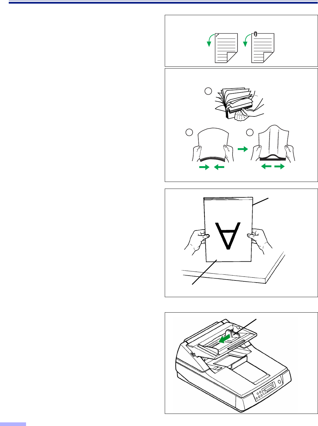
4
Place the documents on the hopper
with the side to be scanned facing up.
Then push them in the direction of the
arrow until they stop.
•Place the documents on the hopper by
matching them with the left side of the
hopper as shown in the diagrams at the
right.
The amount of documents should not
exceed the limit mark on the document
guide. This may cause a paper jam or
skew.
•For different sized documents, place
them with the top left ends facing the left
side of the hopper.
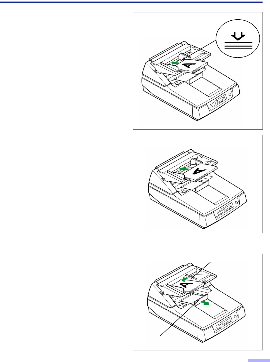
5
Adjust the document guide to the size
of the document to be scanned.
Adjust the exit document stopper to
the size of the document to be output.
Portrait
Fill indicator
(Limit mark)
Document guide
Exit document stopper
Landscape
36
Loading Documents on the ADF
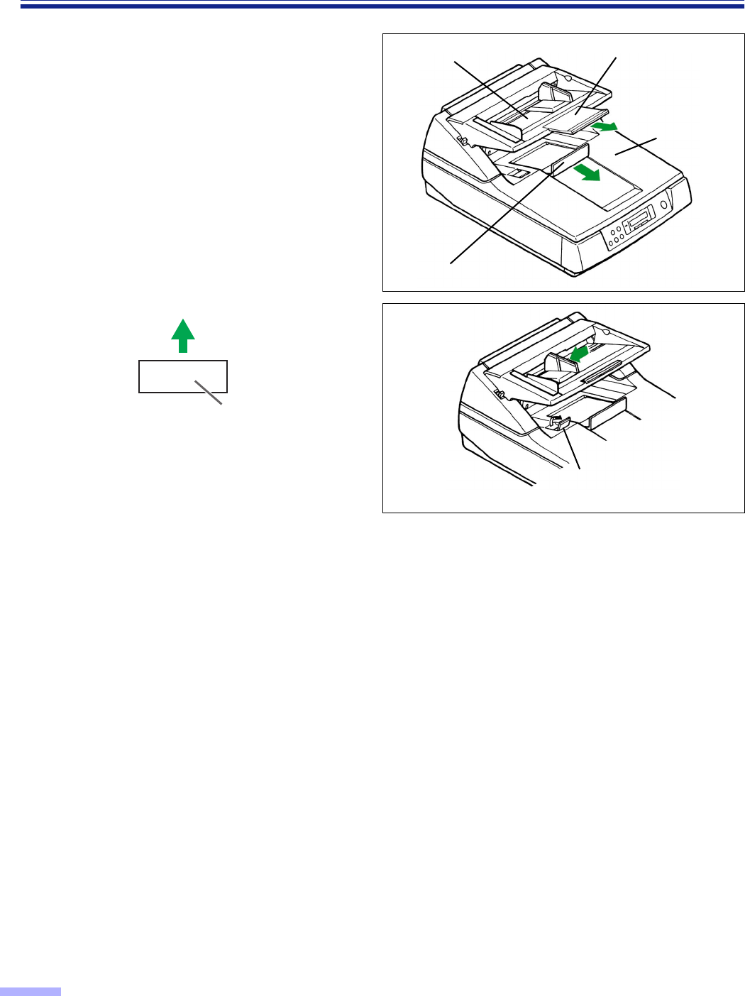
6
When using long paper, pull out the
hopper extension tray from the hopper
and the exit document stopper from
the document cover.
Then adjust the exit document stopper
above the document cover a little
longer than the actual length of the
document by pressing down the exit
document stopper slightly. (See fig. 1.)
•
When scanning narrow documents as
shown below, pull up the exit substopper.
(See fig. 2.)
After using the exit substopper, push
down it.
Cautions:
•
When scanning very fragile documents, scan with the flatbed side. (See page 37.)
•
For thin, thick or important paper, scan the document with the flatbed side or using single sheet (manual feed )
mode (see page 40). Also, remove the document from the document cover after it is scanned by the ADF.
•
The scanner will accept 50 to 127
g
/m
2
(13 to 34 lbs.) paper for continuous scanning and 40 to 127
g
/m
2
(10.6
to 34 lbs.) paper for single scanning.
•
When scanning a thin, folded, creased or curled document by the ADF, after straightening the document, set
the feed speed to “Slow”.
•
When scanning thick documents [64
g
/m
2
(17 lbs.) or more], be sure to use less than 200 sheets.
•
When scanning copying paper such as carbon or carbonless paper, use the flatbed.
•
When setting the document, be sure that it does not exceed the fill indicator (limit mark).
•
Be sure to remove the document from the document cover after it is scanned.
•
When the scanner does not detect a document set in the hopper which has a black or dark area on the
opposite side, add a white sheet of paper under the document.
•
When scanning the different sized documents, exited document may go into the stack of documents on the exit
part and may get out of order.
Types of documents to avoid for the ADF:
•
OHP sheets, other plastic film, cloth, or metallic sheets
•
Paper with irregularities such as tabs, staples, paste, etc.
•
Documents with wet ink
•
Thick or irregular documents such as envelopes, paste, etc.
•
Copying paper such as carbon paper
•
Damaged or wrinkled documents
•
Irregular shaped documents
•
Tracing paper
Scanning direction
Document
Exit document stopper
Document
cover
Hopper extension
tray
Fig. 1
Hopper
Exit substopper
Fig. 2
37
Loading Documents on the Flatbed
One sheet or an entire book document can be scanned on the document glass.
Scanning documents in this way is known as “scanning with the flatbed”.
∫∫
∫∫When scanning with the flatbed one time
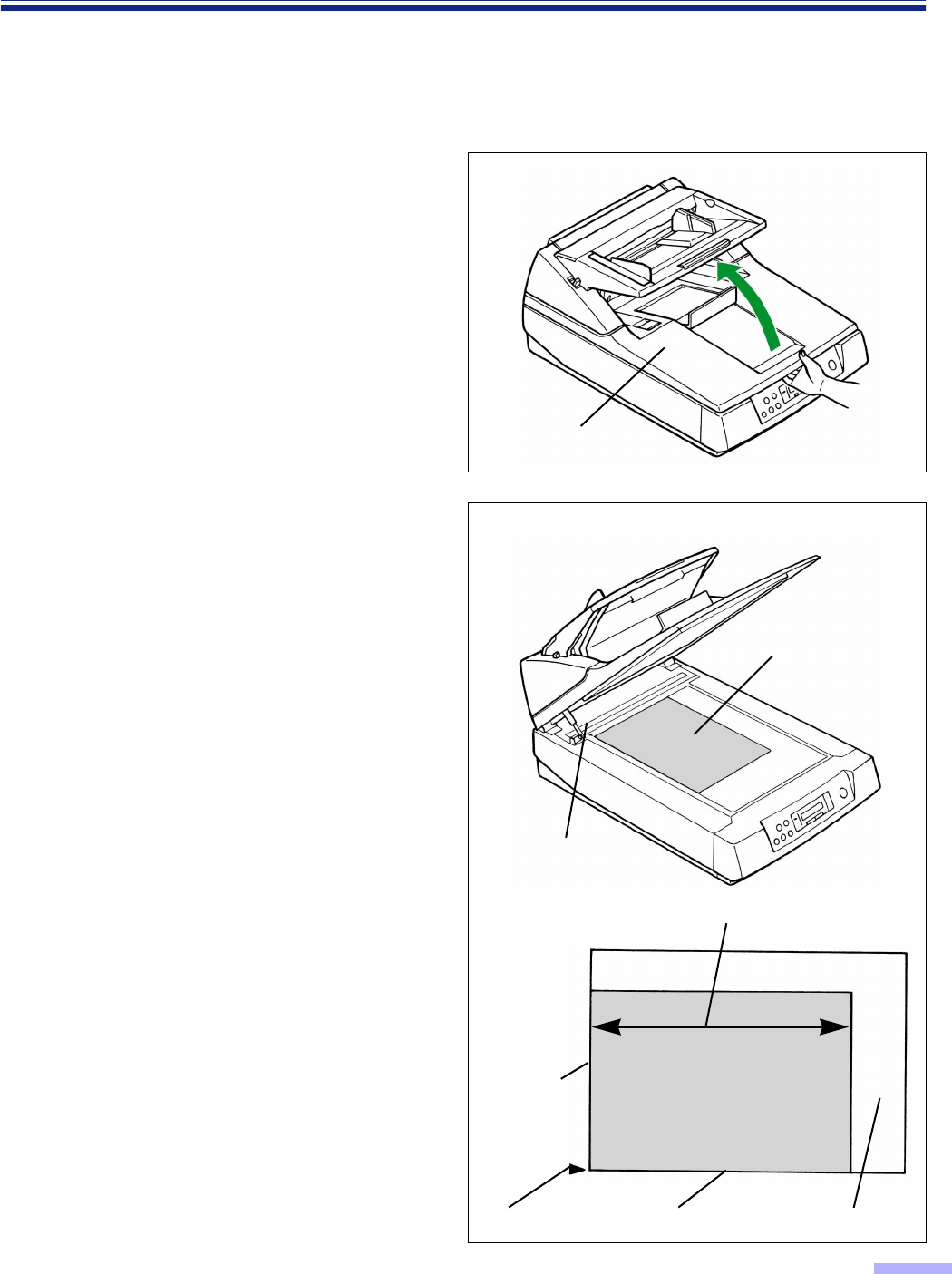
1
Open the document cover.
2
Place the scanning side of the
document face down on top of the
document glass.
•If the document is bent or folded,
straighten it.
3
Match the shorter side of the
document with the left edge of the
document glass.
4
Match the longer side of the document
with the standard mark.
•If the document is slanted, it will not be
scanned properly.
Document cover
Document
Standard mark
Longer side
Shorter side
Standard mark Document Document glass
38
Loading Documents on the Flatbed
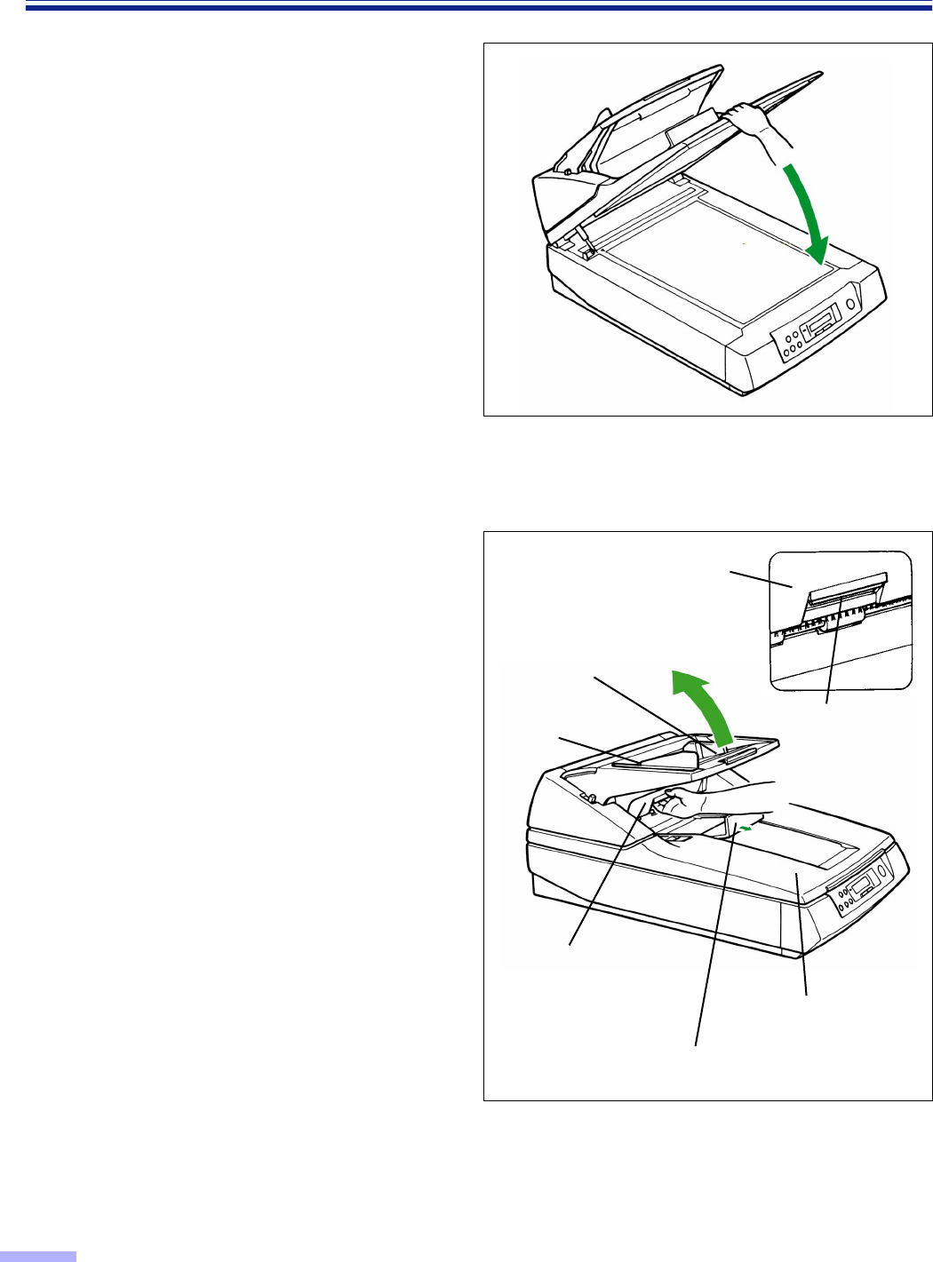
5
Close the document cover gently.
•If the document cover is slammed, the
document will move and may not be
scanned properly.
•Do not open or press down on the
document cover during scanning.
•Do not look directly at the light.
(You may damage your eyes.)
•Be sure to close the document cover
before use.
•After scanning, open the document cover
and remove the document.
∫∫
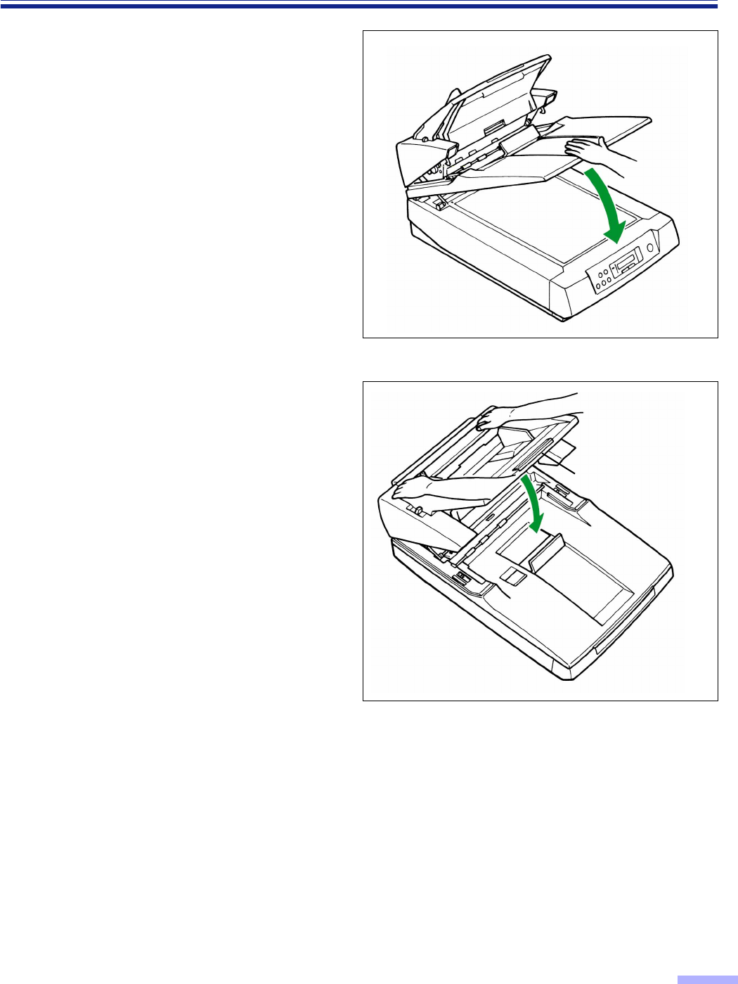
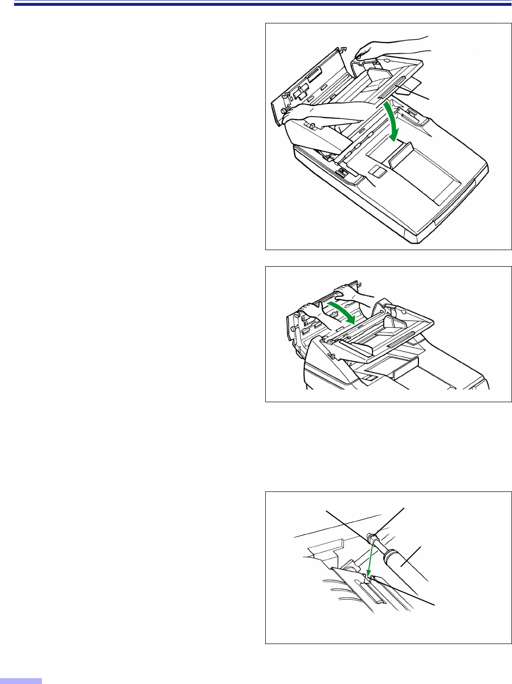
∫∫When scanning with the flatbed repeatedly
The ADF is heavy so when scanning with the flatbed repeatedly, separate the ADF and document cover.
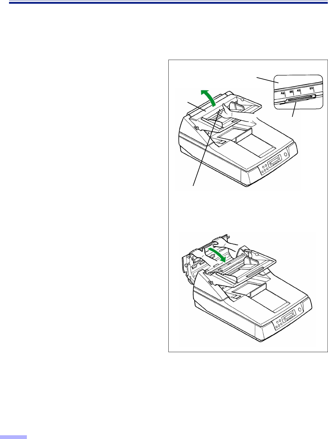
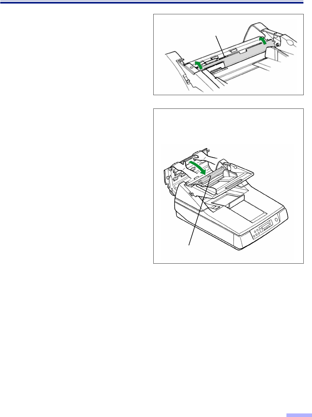
1
Pull the exit document stopper towards
you, pull the front door release under
the hopper, separate the ADF and
document cover, and lift up the ADF to
open.
2
Perform operation steps 1 through 5
for scanning with the flatbed one time.
(See pages 37 and 38.)
ADF
ADF
Exit document stopper
Front door release
(Inside the front door.)
Document cover
Hopper
Front door release
39
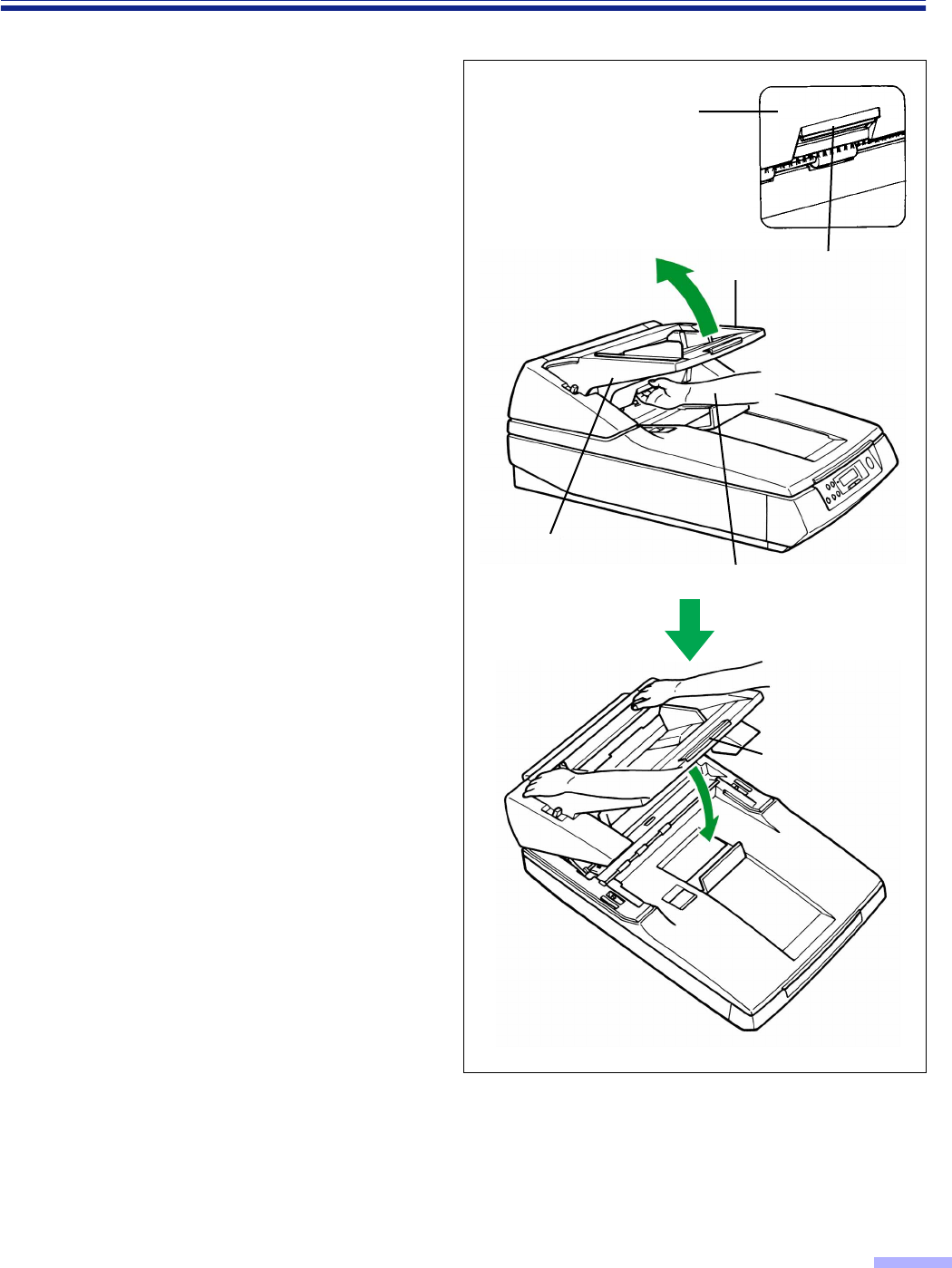
Loading Documents on the Flatbed
3
After scanning, close the document
cover gently.
4
Close the ADF gently.
•Push down on both sides of the ADF
gently until it clicks into place.
•Do not close the ADF holding the hopper
extension tray.
∫∫
∫∫Scanning thick documents
When scanning thick documents such as a book, please note the following items:
• The operation methods when scanning thick document, such as a book, with the flatbed one time and
repeatedly are the same.
• Do not close the document cover forcibly. You may scan with the document cover open.
In this case, do not look directly at the light.
• Please note that areas of the document which are not touching the document glass will not be scanned
properly.
• If the document moves during scanning, please note that it will not be scanned properly.
Hopper extension tray
40
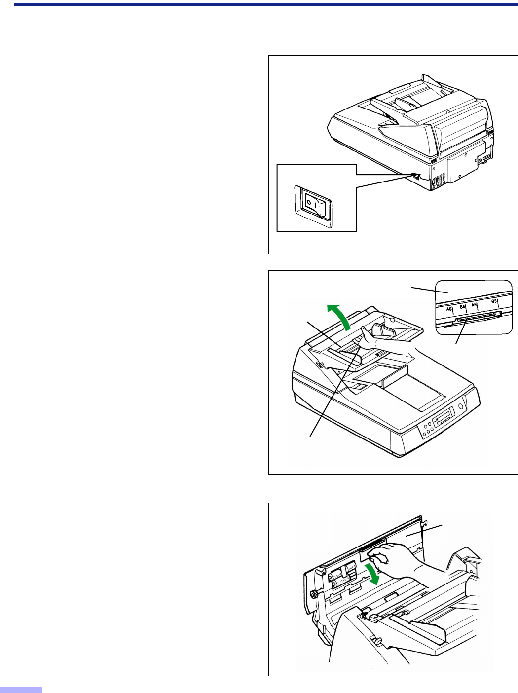
Feeding a Document Manually
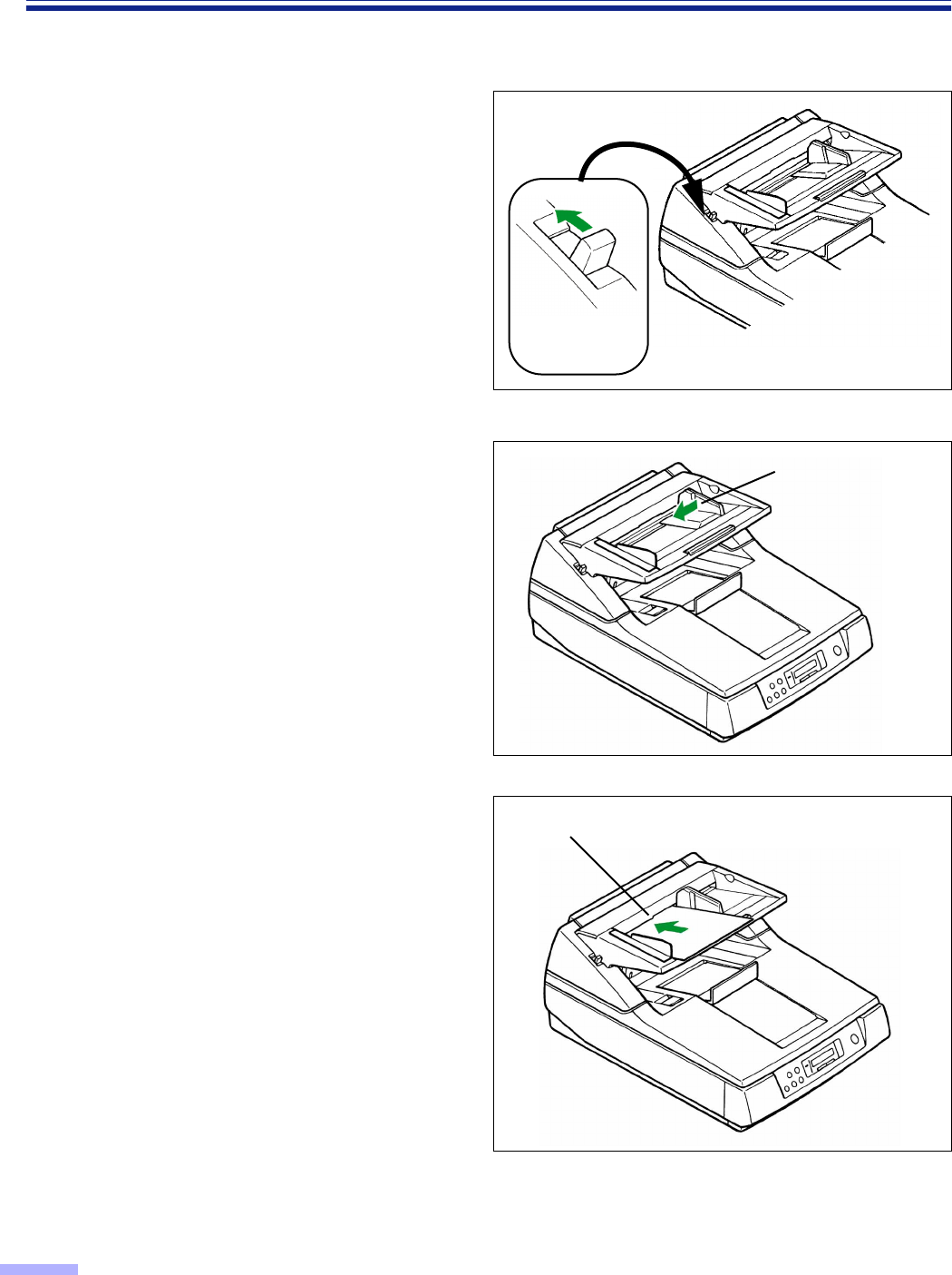
When scanning a document with multiple pages with the ADF, set the manual feed selector to “MANUAL” and the
pages can be scanned one page at a time.
1
Set the manual feed selector to
“MANUAL”.
•The hopper will then be raised to the
proper level for manual feeding.
2
Match the document guide with the
size of the document.
3
Insert the document into the paper slot
one page at a time.
Cautions :
• Please remove any staples from the document before scanning.
• Glued or curled documents may cause a paper jam or damage the unit, so please scan using the flatbed.
Paper slot
Manual feed
selector
Document guide
41
Others
∫∫
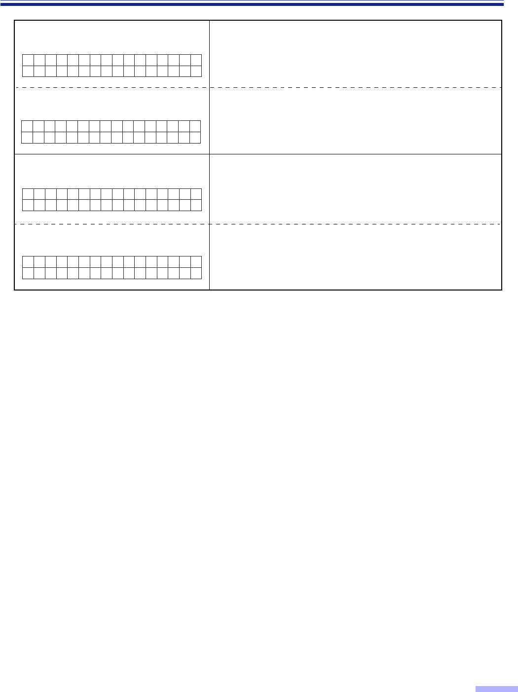
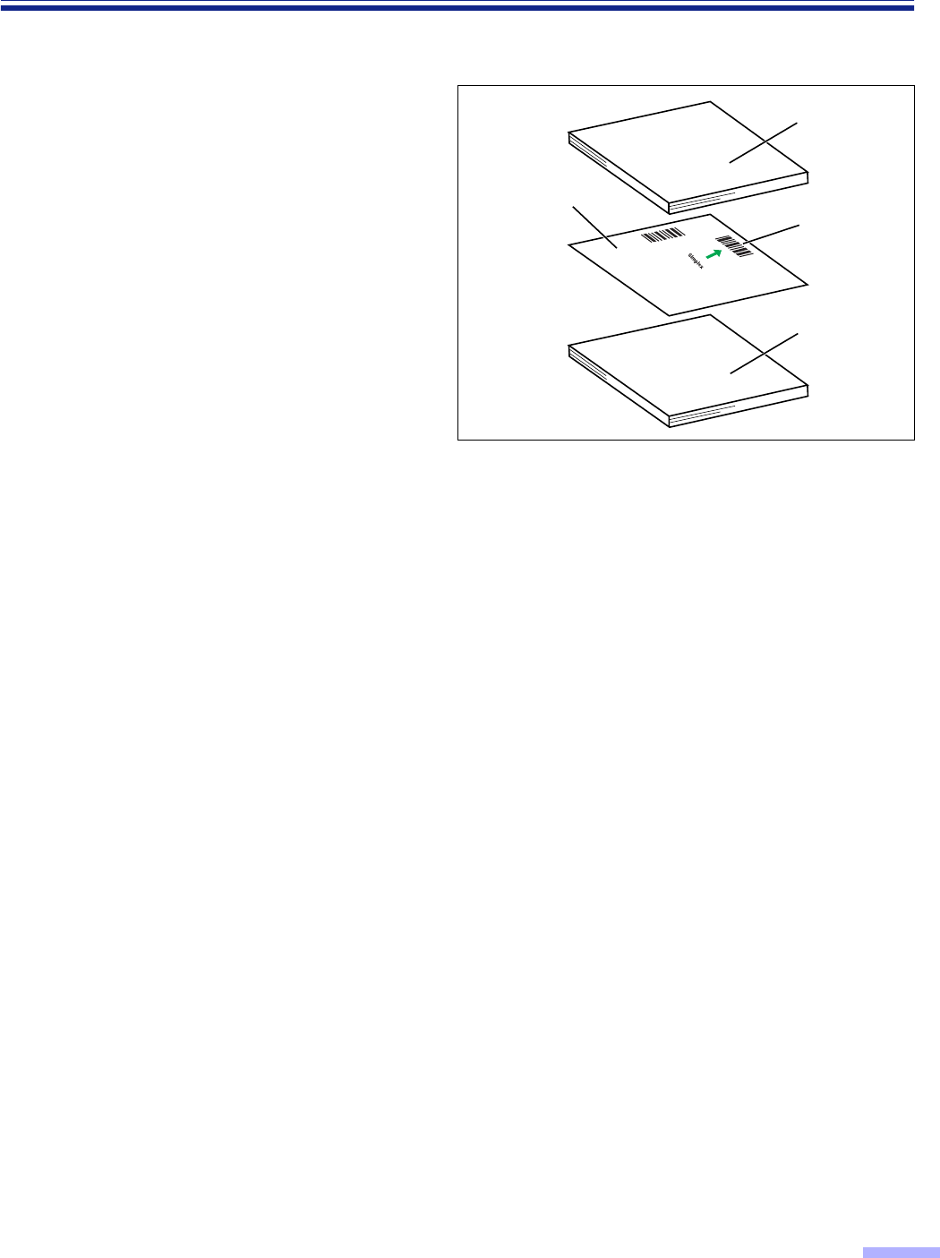
∫∫How to use the control sheet
If the control sheet is used, the documents
under the control sheet are scanned in
accordance with the code on the control
sheet regardless of scanning condition that
is selected previously.
•Multiple control sheets can be used.
•When using a control sheet, the application
software required depends on the control sheet.
•Print out control sheets from the provided CD-
ROM.
Caution
•Use the same size control sheet as the scanning
document.
•When printing the control sheet, if the pattern
falls in the area from the top side of the
document to 25 mm, adjust the printer.
Also, copy the control sheet so that the pattern
lies in the center of the copy.
•Be careful not to get the control sheet dirty.
Do not fold or crease the control sheet.
Scanning will not be performed properly.
Code
Documents
Control sheet
B
A
Documents
42
Clearing Paper Jams
Torn documents, thin documents or documents that are creased on the top edge may cause paper jams. If a paper
jam occurs (“U xx JAM” will be displayed on the LCD), remove the jammed sheet according to the following
procedure.
∫∫
∫∫Removing paper jams from the feed part
Using your hand, hold down the ADF door
release towards you. Open the ADF door
and pull the jammed document towards the
feed part, and then close the ADF door.
•Push both sides of the ADF door down gently
until it clicks into place.
•Since the roller are located on the left side of the
ADF door, there is more weight on the left side.
Therefore, it is important to note that the door
needs to have tension evenly divided to close it
properly.
ADF door
ADF door release
ADF door
ADF door release
(Inside the ADF door.)
43
Clearing Paper Jams
∫∫
∫∫Removing paper jams from the exit path
If a jammed document appears at the exit
part, pull the exit document stopper towards
you, open the front door and pull the
document forward, then close the front door.
•Push both sides of the front door down gently
until it clicks into place.
•Do not close the front door holding the hopper
extension tray.
Front door release
(Inside the front door.) Exit document stopper
Front door
Front door Front door
release
Hopper extension
tray
44
Cleaning the Unit
∫∫
∫∫Outside of the scanner
Clean the unit at least once a month.
1
Turn the power off.
2
Clean the cover with a soft cloth.
•The ADF insertion and exit slots get dirty
easily, therefore, proper cleaning is
required.
3
Remove dirt and dust from the fan
exhaust vent with a brush.
∫∫
∫∫Inside the scanner
Clean the unit described below at least once a week or when 50,000 sheets have been scanned, whichever
comes first.
• Clean the rollers, all document sensors, double feed detection sensors and paper detection sensor if paper
jamming or double feeding occurs frequently.
• Clean the scanning section glass, CIS glass, sensor plate and sensor roller when black or white lines appear on
the scanned images. NOTE : There is no CIS glass and no sensor roller for the KV-S6050W / KV-S6050WU.
• If the documents that will be scanned are dirty, then the scanner parts may become dirty as well.
To maintain proper scanning, clean the scanner parts frequently.
• When scanning with the flatbed and black dots or white patches occur, open the document cover, and clean the
document glass and cover sheet (black sheet) using the accessory roller cleaning paper.
∫∫
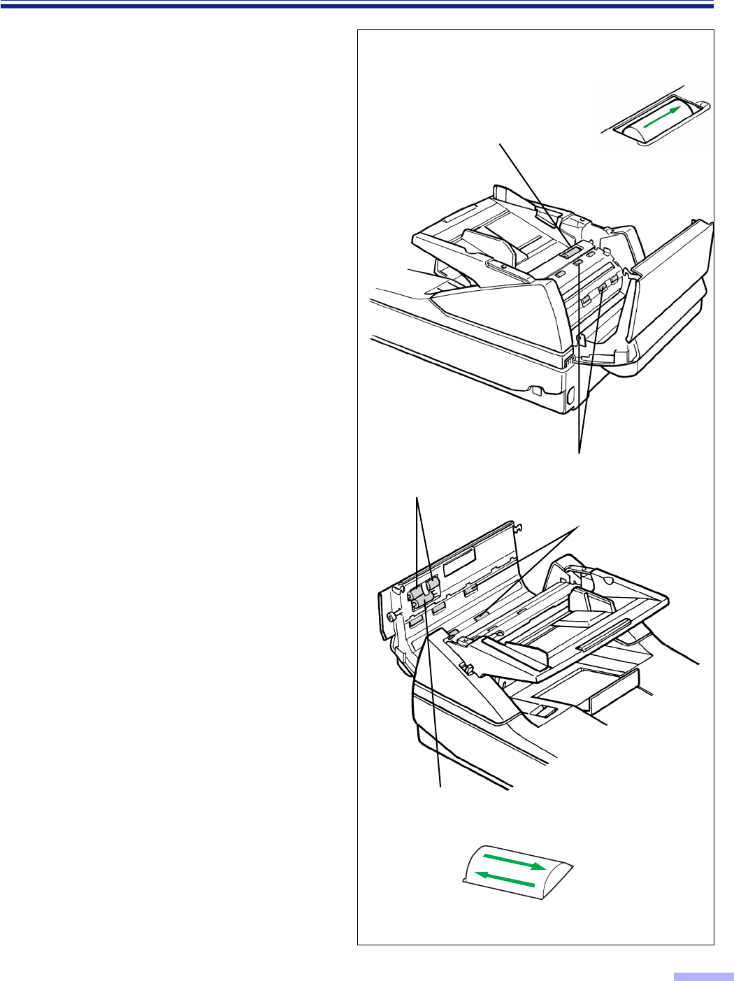
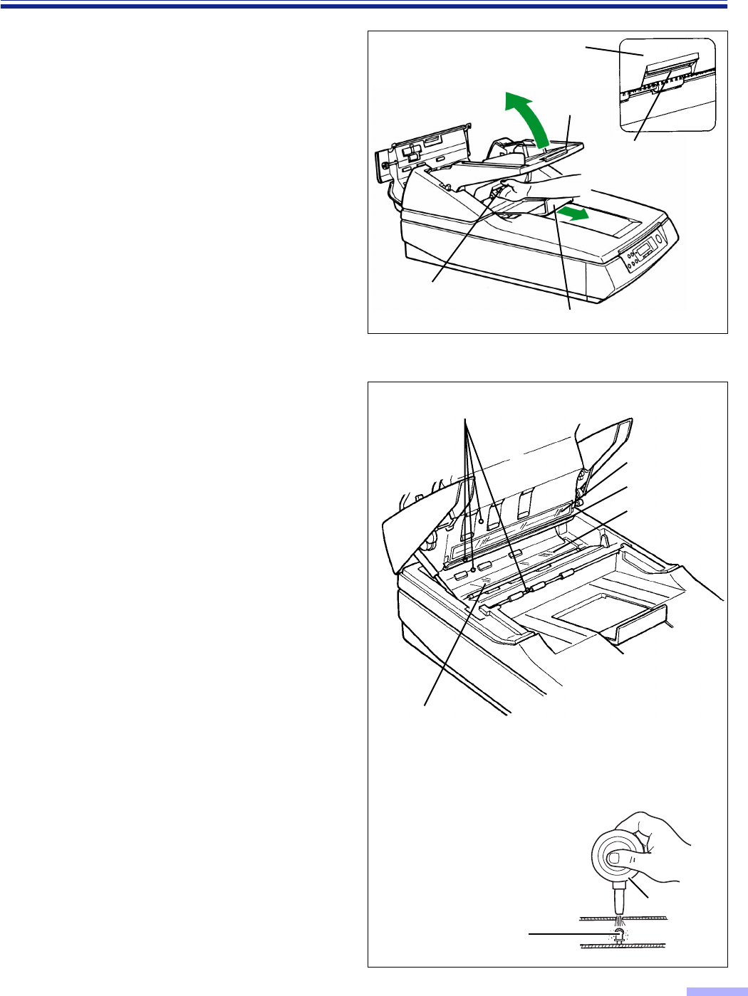
∫∫Cleaning the rollers
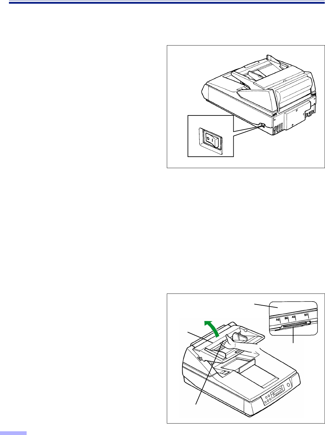
1
Turn the power off.
2
Using your hand, pull the ADF door
release towards you, then open the
ADF door completely.
ADF door
ADF door release
ADF door
ADF door release
(Inside the ADF door.)
≤ : Off position
Power switch
45
Cleaning the Unit
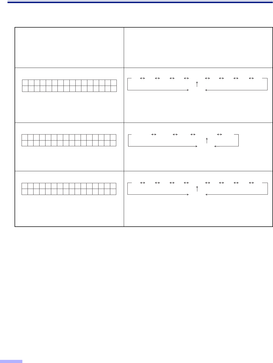
3
Use the accessory roller cleaning
paper (KV-SS03) to remove the dirt
from the surfaces of all rollers.
•When wiping off the dirt, hold the rollers
to prevent them from rotating. Wipe the
rollers completely from one end to the
other. Be sure to wipe in the directions of
the arrows shown on the diagram to the
right.
•Clean the retard roller only in the
directions of the arrow shown on the
diagram to the right. If cleaned in the
wrong direction, the roller may slip out of
the proper position.
Other roller except retard roller
• The rollers to be cleaned are shaded.
• Wipe in the direction of the arrows.
Retard roller
Retard roller
Conveyor rollers
Paper feed rollers
Separation roller
Rollers
46
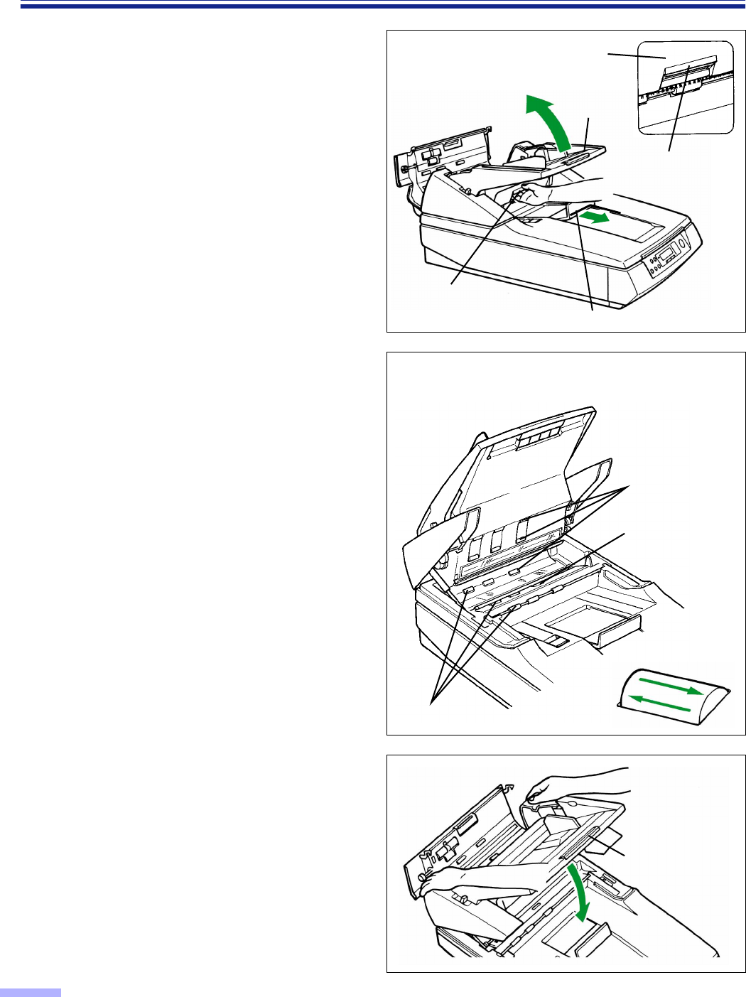
Cleaning the Unit
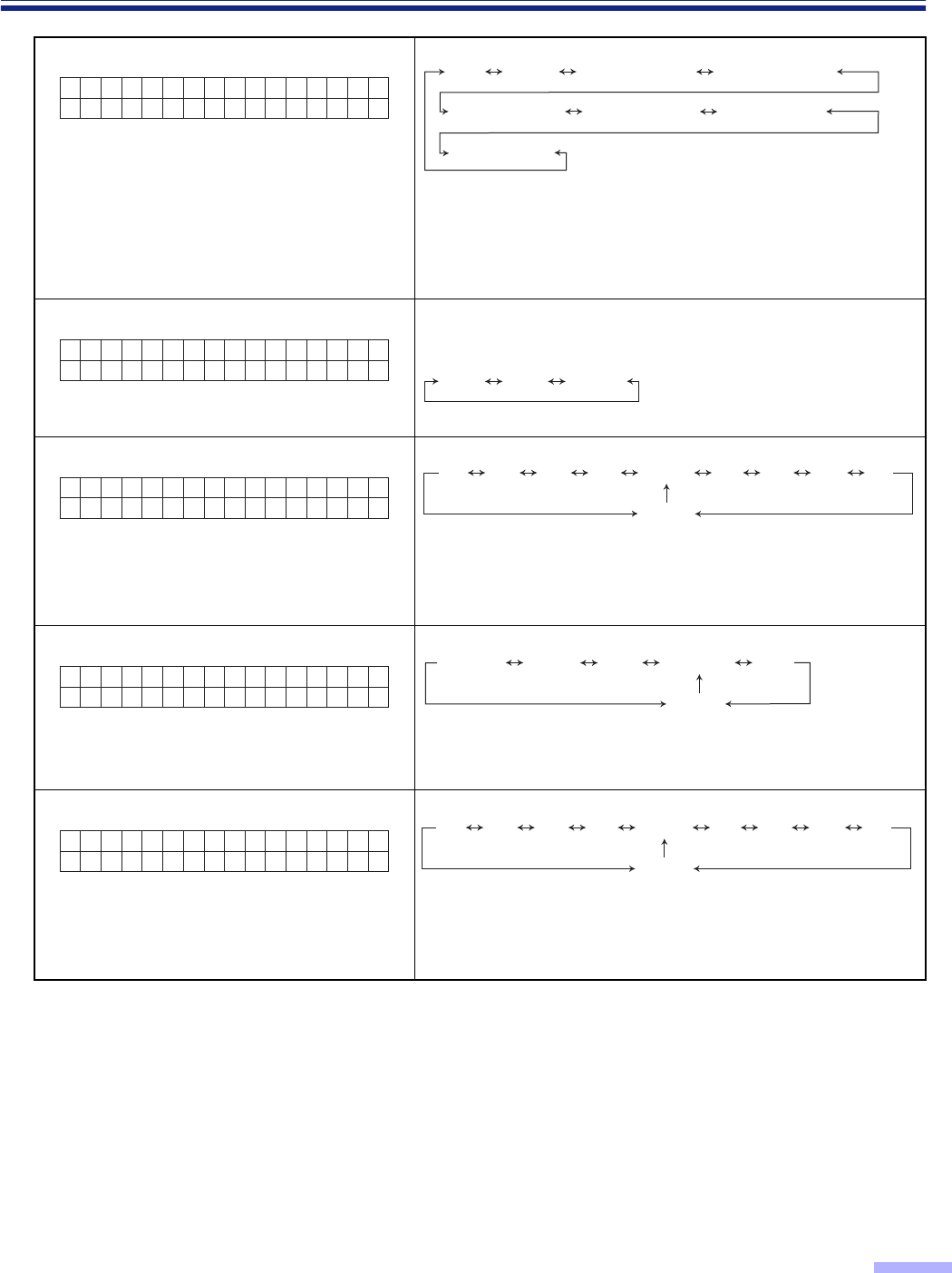
4
Pull the exit document stopper
towards you and use your hand to pull
the front door release towards you.
Then open the front door completely.
5
Use the accessory roller cleaning
paper (KV-SS03) to remove the dirt
from the surfaces of all rollers.
•When wiping off the dirt, hold the rollers
to prevent them from rotating. Wipe the
rollers completely from one end to the
other. Be sure to wipe in the directions of
the arrows shown on the diagram to the
right.
6
Close the front door.
•Push both sides of the front door down
gently until it clicks into place.
•Do not close the front door holding the
hopper extension tray.
Front door release
(Inside the front door )
Front door release
Front door
Front door
Exit document stopper
Hopper extension
tray
•The rollers to be cleaned are shaded.
•Wipe in the direction of the arrows.
Rollers
Sensor roller
Conveyor rollers
47
Cleaning the Unit
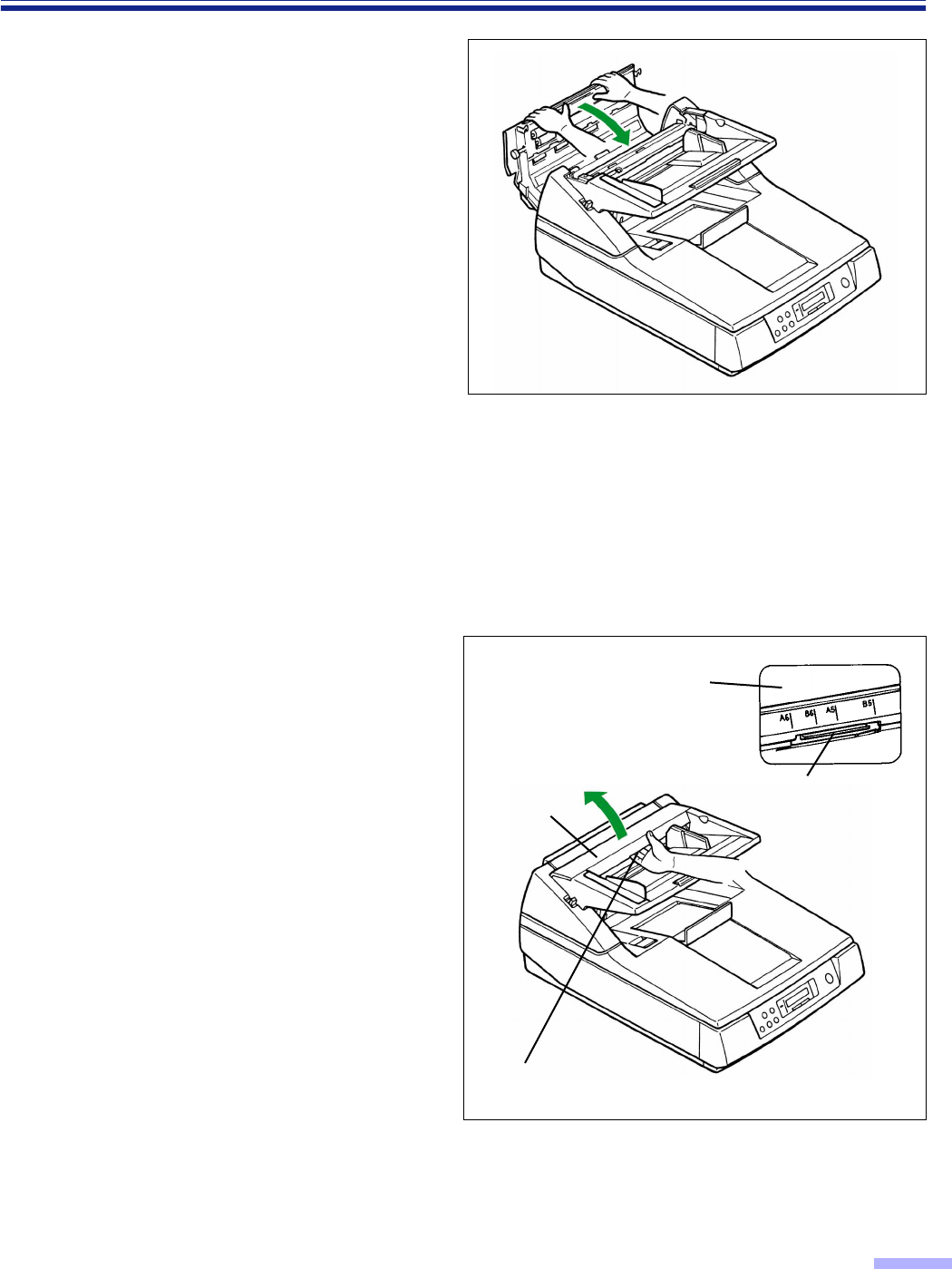
7
Close the ADF door.
•Push both sides of the ADF door down
gently until it clicks into place.
•Since the roller are located on the left
side of the ADF door, there is more
weight on the left side.
Therefore, it is important to note that the
door needs to have tension evenly
divided to close it properly.
∫∫
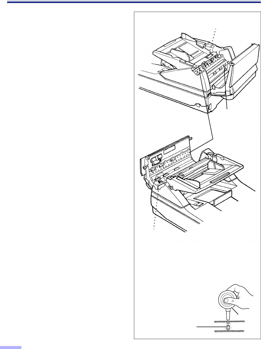
∫∫Cleaning the scanning section glass, CIS glass, sensor plate, sensor roller,
document sensors, double feed detection sensors and paper detection
sensor
1
Turn the power off.
2
Using your hand, pull the ADF door
release towards you, then open the
ADF door completely.
ADF door release
ADF door release
(Inside the ADF door.)
ADF door
ADF door
48
Cleaning the Unit
3
Remove the dirt on the document
sensors, double feed detection sensors
and paper detection sensor using the
included blower.
Blower
Document sensor, double
feed detection sensor or
paper detection sensor
¥¥
¥¥ How to clean the document sensor,
double feed detection sensor or paper
detection sensor
Remove the brush and blow
off the dirt through the document
sensor hole, double feed
detection sensor hole or
paper detection sensor hole.
Double feed
detection sensor
Document sensors
Double feed
detection sensor
Paper detection sensor
49
Cleaning the Unit
4
Pull the exit document stopper
towards you, using your hand, pull the
front door release towards you, then
open the front door completely.
5
Clean the scanning section glass, CIS
glass, sensor plate and sensor roller
using the accessory roller cleaning
paper (KV-SS03).
Also, remove the dirt on the document
sensors using the included blower.
•If the sensor roller is removed while
cleaning, re-attach it after cleaning.
(Refer to page 50 for re-attachmant.)
•There is no CIS glass and no sensor
roller for the KV-S6050W/KV-S6050WU.
Front door release
(Inside the front door )
Front door release
Front door
Front door
Exit document stopper
Blower
Document sensor
Document sensors
CIS glass
Sensor plate
Scanning
section glass
Sensor roller
¥How to clean the document sensor
Remove the brush and blow off
the dirt through the document
sensor hole or directly.
50
Cleaning the Unit
6
Close the front door.
•Push both sides of the front door down
gently until it clicks into place.
•Do not close the front door holding the
hopper extension tray.
7
Close the ADF door.
•Push both sides of the ADF door down
gently until it clicks into place.
•Since the roller are located on the left
side of the ADF door, there is more
weight on the left side.
Therefore, it is important to note that the
door needs to have tension evenly
divided to close it properly.
•After cleaning, clear the “Clean Roller
Warning” display. (See page 31.)
¥Re-attachment of the sensor roller
When the sensor roller is removed while cleaning the inside of the scanner, re-attach it as shown below.
Lower sensor roller:
Attach the roller by placing the no-gear side
to the left side of the scanner and inserting
both side’s bearings into the guide grooves.
•Match the flat side of the bearing with the flat
side of the guide groove.
•After attaching, press down on top of the sensor
roller with your finger to confirm if it moves or
not.
Hopper
extension tray
Sensor roller
Flat side of the bearing
Please attach the right side bearing in the same way.
Bearing
Guide groove
51
Cleaning the Unit
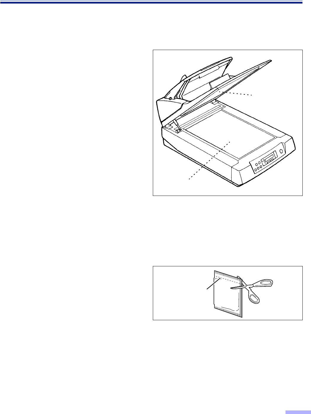
∫∫
∫∫Document glass and cover sheet
1
Open the document cover.
(See step 1 on page 37.)
2
Clean the document glass and cover
sheet (black sheet) using the
accessory roller cleaning paper
(KV-SS03).
3
Close the document cover gently.
(See step 5 on page 38.)
∫∫
∫∫Roller cleaning paper
Open the bag on the dotted line and take out
the roller cleaning paper.
•If the roller cleaning paper bag is left open for a
long period of time before using it, the alcohol
will evaporate. Please use the roller cleaning
paper immediately after opening the bag.
§The roller cleaning paper (Model No. KV-SS03) is available from the dealer where you
purchased your scanner.
For supplies and accessories: Call 1-800-346-4768 (U. S. A. only) or your dealer.
Dotted line
Document glass
Cover sheet
52
Replacing Consumable Roller Modules
If “Warning Replace Roller” message is displayed on the LCD, replace the paper feed roller module, separation
roller module and retard roller module at the same time.
1
Confirm that the manual feed selector
is set to “AUTO”, turn the power off and
unplug the power cord.
•If the power is turned off with the manual
feed selector set to “MANUAL”, the retard
roller module cannot be removed.
2
Using your hand, pull the ADF door
release towards you, then open the
ADF door completely.
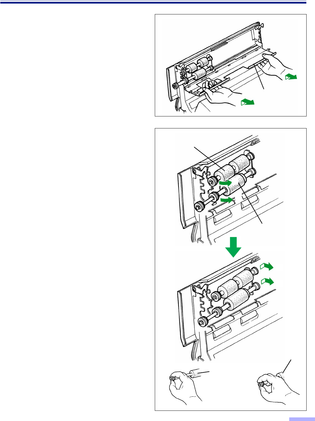
3
Using your fingers, hold the paper feed
conveyor and pull it towards you to
open it.
•When the paper feed conveyor is pulled
towards you, the click-stop mechanism
will be released.
ADF door release
(Inside the ADF door.)
ADF door
ADF door
ADF door release
Paper feed
conveyor
≤ : Off position
Power switch
53
Replacing Consumable Roller Modules
4
Remove the paper feed conveyor by
first lifting it slightly and then pulling it
toward you.
•Do not apply any force or weight to the
paper feed conveyor since doing so may
bend it out of shape.
5
Hold the paper feed roller module gear
and pull the gear side in the direction
of arrow 1. Now slide the gear side in
the direction of arrow 2.
Next, hold the separation roller module
gear and pull the gear side in the
direction of arrow 1, and then slide it
in the direction of arrow 2 to remove
it.
Paper feed roller module
Separation roller
module
Separation
roller module
Paper feed
roller module
1
1
2
2
Paper feed
conveyor
54
Replacing Consumable Roller Modules
6
Open the optional “Roller Exchange
Kit (KV-SS044)”, and take out the
paper feed roller module and
separation roller module.
For supplies and accessories:
Call 1-800-346-4768 (U.S.A. only) or
your dealer.
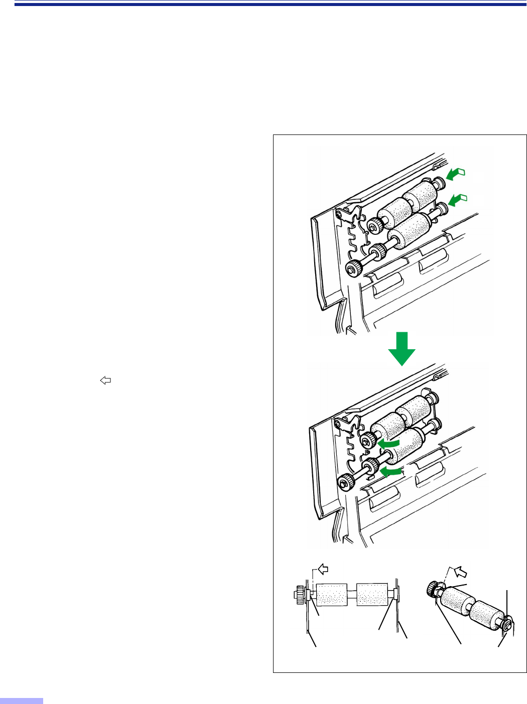
7
Install the new paper feed roller
module and separation roller module
with the gears on the left side and the
post-gear side bearing slide into the
right side guide grooves of the chassis
in the scanner. (1)
Then push up the gear side bearings
and install into the left side guide
grooves of the chassis in the scanner.
When installing the second one, it
clicks into place. (2)
•Match the paper feed roller module and
separation roller module with the
bearings and guide grooves, and then
attach them.
When attaching the paper feed roller
module and separation roller module,
push each bearing in the direction of the
arrow and attach.
•When attaching the paper feed roller
module and separation roller module to
the chassis, do not damage the rollers.
1
1
2
2
Chassis
Bearing BearingChassis Chassises
Bearings
55
Replacing Consumable Roller Modules
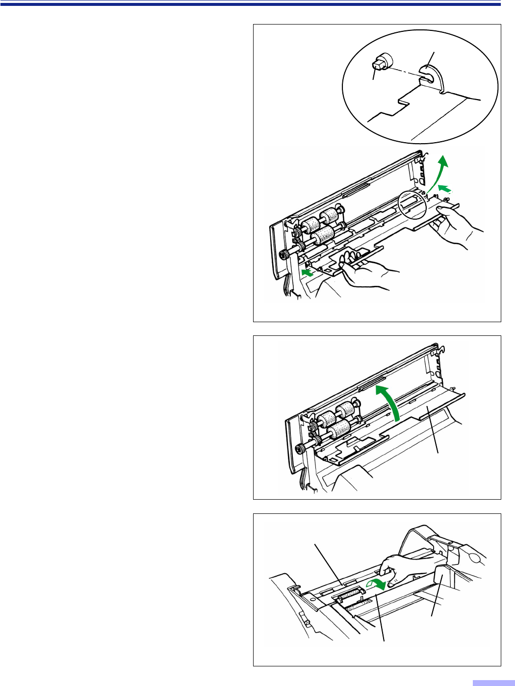
8
Tilt the paper feed conveyor at a slight
angle pointing downward and attach it
as shown in the diagram to the right.
9
Close the paper feed conveyor.
•Push up the paper feed conveyor until it
clicks into place.
•You are now finished attaching the paper
feed roller module and separation roller
module.
To continue, replace the retard roller
module according to the following
procedure. (The retard roller module is
located in the conveyor.)
10
Using your fingers, hold the conveyor
and pull it towards you to open it.
•When the conveyor is pulled towards you,
the click-stop mechanism will be
released.
Hook
Pin
Please attach the left side hook in the same way.
Paper feed
conveyor
Retard roller module
Conveyor
Document guide
56
Replacing Consumable Roller Modules
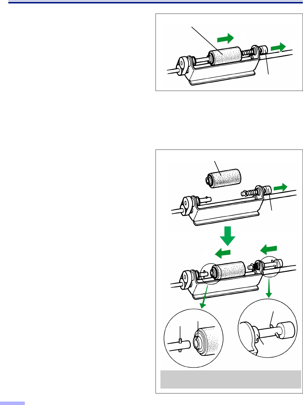
11
Pull the right side of the shaft in the
direction of arrow (1), and hold it
there.
Pull the retard roller module in the
direction of arrow (2), and then
remove it.
12
Take out the retard roller module in the
optional “Roller Exchange Kit
(KV-SS044)”.
For supplies and accessories:
Call 1-800-346-4768 (U.S.A. only) or
your dealer.
13
Pull the right side of the shaft in the
direction of arrow (1) and hold it
there.
Attach the new retard roller module as
shown in the direction of arrow (2).
Return the right side of the shaft as
shown in the direction of arrow (3).
•Confirm if pin A and pin B are inserted in
their notches correctly.
•Attach the retard roller module so that the
notch A is on the left side.
1
2
Retard roller module
Shaft
Retard roller module
When the pin is not inserted in the notch properly,
it may cause double feeding or a paper jam.
Shaft
1
23
Notch A
Pin A
Pin B
Notch B
57
Replacing Consumable Roller Modules
14
Close the conveyor by pushing it into
the unit.
•When the conveyor is closed, the click-
stop mechanism will operate.
•If the conveyor is not closed correctly
and the operation in step 15 is done, the
conveyor may break.
15
Close the ADF door.
•Push both sides of the ADF door down
gently until it clicks into place.
•Since the roller are located on the left
side of the ADF door, there is more
weight on the left side.
Therefore, it is important to note that the
door needs to have tension evenly
divided to close it properly.
•After replacing roller modules, clear the
“Replace Roll. Warning” display.
(Refer to page 31.)
Conveyor
Before closing the ADF door, confirm
that the conveyor is closed correctly.
If it is not, the conveyor may break.
Conveyor
58
Repacking Instructions
It is highly recommended that you keep the original carton and ALL packing materials. lf you need to transport or
ship your scanner, please follow these instructions.
Please Note :
•Please use the original carton and all of the original packing materials. If you do not have the original packing
materials, these are available from your Panasonic dealer. Please refer to your service dealer, or call 1-800-833-
9626 (U.S.A. only) or your dealer.
•Improper repacking of the scanner may result in a service charge to repair the unit.
•The scanner should be handled in the correct (horizontal) position.
Materials Required :
•Original Scanner Carton & Packing Materials
•Shipping Tape and Scissors
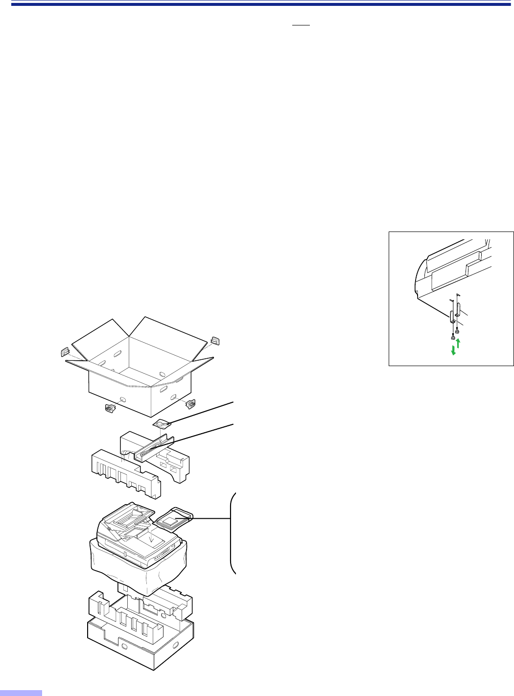
1
Disconnect your scanner from the electrical outlet and the interface cable.
2
Fix the optical unit of the flatbed and attach the protective sheets with tapes.
•Please refer to the installation manual enclosed with the unit.
•Turn the power on and complete initializing (return the optical unit to
the original position), then attach the metal clamp at position A .
3
Pack the scanner. A
B
Blower
Power cord
KV-S6050W/KV-S6055W
(1 piece)
KV-S6050WU/KV-S6055W
U
(2 pieces)
CD-ROM
(Operating instructions)
(Driver software)
Installation manual
Maintenance manual
Roller cleaning paper
(3 pieces)

59
Specifications
•
“Weight in pounds” of paper represents the weight of 500 [ 432
a
559mm (17
a
22 inches)] sheets.
•
The red lamp option (KV-SS045) must be installed by a trained service engineer. Consult your dealer.
•
If the red lamp is installed, any red letters on the back side of the document will automatically not be scanned.
Model No.
Item
KV-S6050W KV-S6055W
Scanner
Scanning face Simplex scanning Duplex scanning
Scanning method CCD image sensor
ADF front side/Flatbed :
CCD image sensor
ADF back side :
CIS (Contact Type Image Sensor)
Readout speed
Flatbed 1.5 sec (1 paper, letter size, 200 dpi)
ADF
Simplex scanning :
Approx. 56 sheets/min. (Letter, fed lengthwise, 200 dpi)
Approx. 53 sheets/min. (A4, fed lengthwise, 200 dpi)
Duplex scanning (KV-S6055W only) :
Approx. 46 sheets/min. (Letter, fed lengthwise, 200 dpi)
Approx. 45 sheets/min. (A4, fed lengthwise, 200 dpi)
Resolution Flatbed/ADF Main scanning direction : 100
T
600dpi (1 dpi step)
Sub-scanning direction : 100
T
600dpi (1 dpi step)
The optical resolution is 400 dpi.
Tonal gradation Binary mode, Grayscale mode (4/8 bit), 64-step gradation
(dither) mode, 64-step gradation (error diffusion) mode
Image control Image emphasis, Dynamic threshold (DIMM required),
Automatic threshold, Automatic separation, Monochrome
reversing, Automatic back control
Paper
Size for Flatbed
T
298
a
432mm (11.7
a
17 in.)
Size for ADF
Scanning size :
70
a
169mm (2.8
a
6.7 in.), and
106
a
148mm (4.2
a
5.8 in.) to 298
a
432mm (11.7
a
17 in.)
Feeding size :
70
a
169mm (2.8
a
6.7 in.), and
106
a
148mm (4.2
a
5.8 in.) to 305
a
432mm (12
a
17 in.)
Thickness for ADF Single paper feeding : 0.05 to 0.15mm (2.0 to 5.9 mils)
Continuous paper feeding : 0.06 to 0.15mm (2.4 to 5.9 mils)
Note : 1 mil=1/1000 in.
Weight for ADF Single paper feeding : 40 to 127
g
/m
2
(10.6 to 34 lbs.)
Continuous paper feeding : 50 to 127
g
/m
2
(13 to 34 lbs.)
Hopper capacity 200 sheets [64
g
/m
2
(17 lbs.), un used paper]
Unit
External dimensions (Width
a
Depth
a
Height) 464
aa
aa
717
aa
aa
296mm (18.3
aa
aa
28.2
aa
aa
11.7 in.)
Mass (Weight) 30k
g
(66 lbs.)
Power requirement AC100 - 120V, 50/60Hz
Power consumption
Maximum (Scanning) 1.8A
Minimum (Standby) 0.5A
Sleep mode 0.13A
Operating
Environment
Operating temperature and humidity 15°C to 30°C (59°F to 86°F), 30% to 80%RH
Storage
Environment
Storage temperature and humidity 0°C to 35°C (32°F to 95°F), 10% to 80%RH
Option
Roller exchange kit (KV-SS044), lmprinter unit (KV-SS010), Red lamp option (KV-SS045),
Roller cleaning paper (KV-SS03), Ink cartridge (KV-SS06), White roller kit (KV-SS049)
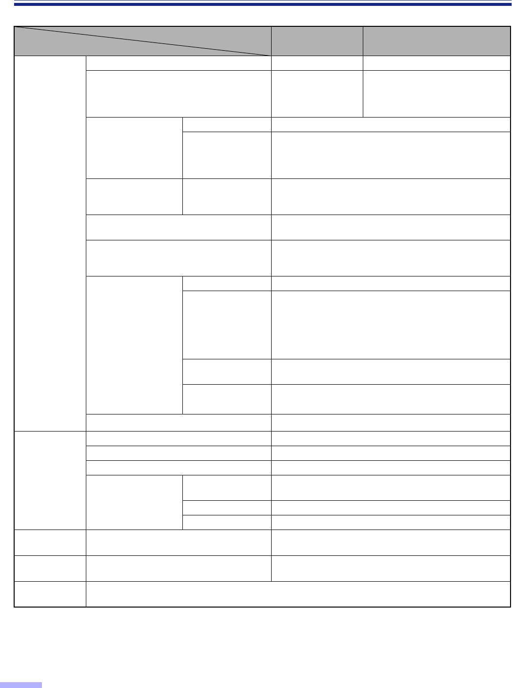
Specifications
60
•
The red lamp option (KV-SS045) must be installed by a trained service engineer. Consult your dealer.
•
If the red lamp is installed, any red letters on the back side of the document will automatically not be scanned.
Model No.
Item
KV-S6050WU KV-S6055WU
Scanner
Scanning face Simplex scanning Duplex scanning
Scanning method CCD image sensor
ADF front side/Flatbed :
CCD image sensor
ADF back side :
CIS (Contact Type Image Sensor)
Readout speed
Flatbed 1.5 sec (1 paper, A4 size, 200 dpi)
ADF
Simplex scanning :
Duplex scanning :
(KV-S6055W only)
Approx. 53 sheets/min.
(A4, fed lengthwise, 200 dpi)
Approx. 45 sheets/min.
(A4, fed lengthwise, 200 dpi)
Resolution Flatbed/ADF Main scanning direction : 100
T
600dpi (1 dpi step)
Sub-scanning direction : 100
T
600dpi (1 dpi step)
The optical resolution is 400 dpi.
Tonal gradation Binary mode, Grayscale mode (4/8 bit), 64-step gradation
(dither) mode, 64-step gradation (error diffusion) mode
Image control Image emphasis, Dynamic threshold (DIMM required),
Automatic threshold, Automatic separation, Monochrome
reversing, Automatic back control
Paper
Size for Flatbed
T
298
a
432mm
Size for ADF
Scanning size :
70
a
169mm, and
106
a
148mm to 298
a
432mm
Feeding size :
70
a
169mm, and
106
a
148mm to 305
a
432mm
Thickness for ADF Single paper feeding : 0.05 to 0.15mm
Continuous paper feeding : 0.06 to 0.15mm
Weight for ADF Single paper feeding : 40 to 127
g
/m
2
Continuous paper feeding : 50 to 127
g
/m
2
Hopper capacity 200 sheets [64
g
/m
2
, un used paper]
Unit
External dimensions (Width
a
Depth
a
Height) 464
aa
aa
717
aa
aa
296mm
Mass (Weight) 30k
g
Power requirement AC220 - 240V, 50/60Hz
Power consumption
Maximum
(Scanning) 1.0A
Minimum (Standby) 0.3A
Sleep mode 0.07A
Operating
Environment
Operating temperature and humidity 15°C to 30°C, 30% to 80%RH
Storage
Environment
Storage temperature and humidity 0°C to 35°C, 10% to 80%RH
Option
Roller exchange kit (KV-SS044), lmprinter unit (KV-SS010), Red lamp option (KV-SS045),
Roller cleaning paper (KV-SS03), Ink cartridge (KV-SS06), White roller kit (KV-SS049)

61
Troubleshooting
If a problem occurs while the unit is being used, first check the following items. If the unit still malfunctions, turn it
OFF, unplug the power cord and call for service.
Symptom Possible Cause Remedy
The LCD does not display
when the power switch is
turned ON.
The power cord is not plugged in. Insert the power plug firmly.
A fuse has blown. Pull out the power plug, then call for
service.
Foreign matter is lodged in the fan,
preventing it from rotating.
The scanner rattels during
initialization after turning
on, and the LCD displays
“F41 Call Service”.
The optical unit of flatbed remains affixed
by the metal clamp.
Remove the metal clamp and re-attach it
at the proper position (position
B
).
(Refer to “Installation” on the Installation
Manual.)
Double feeding problem
occurs.
The rollers are dirty. Clean all of the rollers.
(See pages 44 through 47.)
Retard roller is not installed correctly.
The document stops
during scanning in the
ADF.
The document is creased or torn, or longer
than A3 size or smaller than 106
a
148mm
(4.2
a
5.8 in).
Make a copy of the document on paper
of the specified size [between
106
a
148mm (4.2
a
5.8 in.) and A3 size]
and scan the copy.
The document is jammed. Open the front or ADF door and remove
the jammed paper.
(See pages 63 and 64.)
The document is not fed
smoothly into the ADF
during scanning.
The rollers are dirty. Clean all of the rollers.
(See pages 44 through 47.)
Paper feed rollers, separation roller and
retard roller are the end of their life.
Replace paper feed roller module,
separation roller module and retard roller
module. (See pages 52 through 57.)
The scanned document is
blank.
The document to be scanned was loaded
face down (upside down). Load the document correctly.
The scanning conditions are set on the
computer side but the scanner condition
setting for each item have not become
“Host”.
Return all of the scanning conditions for
each item’s setting to “Host”.
The scanned document is
skewed.
The document guides were not touching
the edges of the document, or the
document was skewed when loaded.
Set the document guides or the
document correctly.
Vertical lines appear on
the scanned document. The sensor roller, scanning section glass
or the rubber rollers are dirty. Wipe the dirty parts with a clean cloth.
(See pages 47 through 50.)
The scanned document is
faint. The sensor roller is dirty. Clean the sensor roller.
(See pages 47 through 50.)
The computer does not
recognize the scanner. The computer cannot recognize the
scanner.
Turn the computer OFF. Turn the scanner
ON, and then turn the computer ON again.
Confirm the SCSI ID, product ID and
terminator, and then set them correctly.
Use a shielded cable which is as short
as possible. Reduce the SCSI transfer
rate, and then proceed.

62
Troubleshooting
Symptom Possible Cause Remedy
The double feed detection
sensor is not operating.
There is dust from the paper on the
double feed detection sensor.
Please clean the double feed detection
sensor with the included blower.
(See page 48.)
The double feed detector sensitivity
setting does not match the scanning
document.
Change the double feed detector
sensitivity setting. (See page 25.)
Black dots or white
patches occur when
scanning with flatbed.
The document glass and cover sheet are
dirty. Clean the document glass and cover
sheet. (See page 51.)
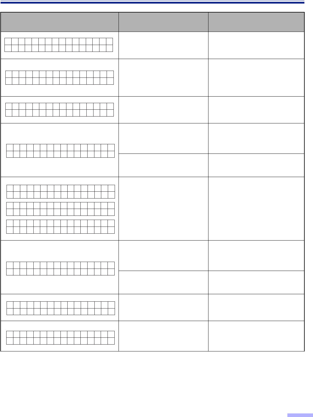
63
Troubleshooting
LCD Possible Cause Remedy
The rollers are dirty. Clean the rollers.
(See pages 44 through 47.)
The rollers need to be
replaced.
Replace the paper feed roller
module, separation roller module
and retard roller module.
(See pages 52 through 57.)
Double feed may have
occurred. Check the scanned data.
The document is jammed. Open the front or ADF door and
remove the jammed paper.
(See pages 42 and 43.)
Dust adheres to the paper
detection sensor. Clean a dust using the included
blower. (See page 48.)
The document is jammed or
the document has been feeded
obliquely.
Open the front or ADF door and
remove the jammed paper.
(See pages 42 and 43.)
A document remains in the
scanner.
Open the front or ADF door and
remove all of the remaining
documents.
Dust adheres to the document
sensors. Clean a dust using the included
blower. (See pages 48 and 49.)
A document has been feeded
obliquely. Open the ADF door and remove
the paper.
Multiple sheets were fed into
the unit.
Open the front or ADF door and
remove the jammed paper.
(See pages 42 and 43.)
✽✽✽Warn
Cl ean Ro l l er
ing✽✽✽
✽✽✽Warn
Rep l ace Ro l l er
ing✽✽✽
✽✽✽Warn
Db l Feed Ocu r r ed
ing✽✽✽
U11 JAM
✕✕✕✕✕✕✕✕
U12 JAM
✕✕✕✕✕✕✕✕
U14 JAM
✕✕✕✕✕✕✕✕
U16 JAM
✕✕✕✕✕✕✕✕
U1 8 Rema
✕✕✕✕✕✕✕✕
ind Doc.
U20 Skew
✕✕✕✕✕✕✕✕
E r r o r
U23 Doub
✕✕✕✕✕✕✕✕
l e Feed
64
Troubleshooting
LCD Possible Cause Remedy
The front door is open. Close the front door .
The ADF door is open. Close the ADF door.
The imprinter (top) door is
open. Close the imprinter door.
The document cover is open. Close the document cover.
A user non-servicable error
has occurred.
Please consult with a service
representative.
Call technical service support.
An interface board has not
been installed. Reinstall scanner’s interface
board.
U30 F r on
✕✕✕✕✕✕✕✕
tDoor
U31 ADF
✕✕✕✕✕✕✕✕
D o o r
U34 Top
✕✕✕✕✕✕✕✕
Doo r
U35 Doc .
✕✕✕✕✕✕✕✕
Cover
H✕✕ Ca l l
✕✕✕✕✕✕✕✕
Service
F✕✕ Ca l l
✕✕✕✕✕✕✕✕
Service
U50 No I
✕✕✕✕✕✕✕✕
/F Board

65
Index
page
A
AC inlet
. . . . . . . . . . . . . . . . . . . . . . . . . . . 13
ADF door
. . . . . . . . . . . . . . . . . . . . . . . 13,
42
ADF door release
. . . . . . . . . . . . . . . . . 13,
42
B
Back side brightness
. . . . . . . . . . . . . . 17,
23
Back side contrast
. . . . . . . . . . . . . . . . 17,
23
Back side halftone
. . . . . . . . . . . . . . . . 17,
24
Back side image emphasis
. . . . . . . . . 17,
23
Bayer dither 16 . . . . . . . . . . . . . . . . . . . 23,
24
Bayer dither 64 . . . . . . . . . . . . . . . . . . . 23,
24
Binary
. . . . . . . . . . . . . . . . . . . . . . . . . . 23,
24
Black line removal
. . . . . . . . . . . . . . . . 17,
24
C
Carbon or carbonless paper
. . . . . . . . . . . 36
Checking the “Roller Cleaning
Warning”. . . . . . . . . . . . . . . . . . . . . . 20,
31
Checking the Firmware Version . . . . . . 20,
30
Checking the roller modules
replacement warning
. . . . . . . . . . . 20,
31
CIS glass
. . . . . . . . . . . . . . . . . . . . . . 14,
47
Clear the “User Counter”
. . . . . . . . . . . . . 19
Clearing the “Roller Cleaning
Warning”
. . . . . . . . . . . . . . . . . . . . 20,
31
Clearing the roller modules replacement
warning
. . . . . . . . . . . . . . . . . . . . . 20,
31
Connector
. . . . . . . . . . . . . . . . . . . . . . . . 13
Control sheet . . . . . . . . . . . . . . . . . . . . . . 41
Conveyor
. . . . . . . . . . . . . . . . . . . . . . . . . 55
COUNTER
. . . . . . . . . . . . . . . . . . . . . 15,
19
Counter
. . . . . . . . . . . . . . . . . . . . . . . . . . 19
Counter setting menu
. . . . . . . . . . . . . . . 19
Cover sheet
. . . . . . . . . . . . . . . . . . . . 14,
51
page
D
Default
. . . . . . . . . . . . . . . . . . . . . . . . . . . 18
Detect
. . . . . . . . . . . . . . . . . . . . . . . . . . . . 18
Display panel
. . . . . . . . . . . . . . . . . . . 13,
15
Document glass
. . . . . . . . . . . . . . . . . 14,
51
Document guide
. . . . . . . . . . . . . . . . . 13,
35
Document sensor
. . . . . . . . . . . . . . . . 44,
47
Double feed detection
. . . . . . . . . . . . 17,
24
E
Error diffusion
. . . . . . . . . . . . . . . . . . . 23,
24
Exit document stopper
. . . . . . . . . . . . 13,
35
F
Fan exhaust vent
. . . . . . . . . . . . . . . . 13,
44
Fill indicator
. . . . . . . . . . . . . . . . . . . . 35,
36
Front door release
. . . . . . . . . . . . . . . 13,
38
Front side brightness
. . . . . . . . . . . . . 17,
22
Front side contrast
. . . . . . . . . . . . . . . 17,
22
Front side halftone
. . . . . . . . . . . . . . . 17,
23
Front side image emphasis
. . . . . . . . 17,
22
H
Halftone dot 32
. . . . . . . . . . . . . . . . . . 23,
24
Halftone dot 64
. . . . . . . . . . . . . . . . . . 23,
24
High
. . . . . . . . . . . . . . . . . . . . . . . . . . . . . 23
HOME
. . . . . . . . . . . . . . . . . . . . . . . . . . . 15
Hopper
. . . . . . . . . . . . . . . . . . . . . . . . 13,
35
Hopper extension tray
. . . . . . . . . . . . 13,
36
Host
. . . . . . . . . . . . . . . . . . . . . . . . . . 28,
29
I
IMPRINT
. . . . . . . . . . . . . . . . . . . . . . 15,
28
Imprinter door
. . . . . . . . . . . . . . . . . . . . . . 13
Imprinter setting menu
. . . . . . . . . . . . . . . 28

66
Index
page
L
Landscape
. . . . . . . . . . . . . . . . . . . . . . . . . 35
LCD (Liquid Crystal Display)
. . . . . . . . . . 15
Load scanning setting
. . . . . . . . . . . . 18,
26
Low
. . . . . . . . . . . . . . . . . . . . . . . . . . . . . 23
M
Manual feed selector
. . . . . . . . . . . . . 13,
40
Medium
. . . . . . . . . . . . . . . . . . . . . . . 22,
23
Menu
. . . . . . . . . . . . . . . . . . . . . . . . . . . . 15
N
Noise reduction
. . . . . . . . . . . . . . . . . 17,
24
None
. . . . . . . . . . . . . . . . . . . . . . . . . 22,
23
Norm
. . . . . . . . . . . . . . . . . . . . . . . . . 22,
23
Normal
. . . . . . . . . . . . . . . . . . . . . . . . . . . 25
Not detect
. . . . . . . . . . . . . . . . . . . . . 24,
25
O
Operating environment
. . . . . . . . . . . 59,
60
Others
. . . . . . . . . . . . . . . . . . . . . . . . . . . 41
P
Paper detection sensor
. . . . . . . . . . . 47,
48
Paper feed conveyor
. . . . . . . . . . . . . . . . 52
Paper feed roller module . . . . . . . . . . . . . 53
Portrait
. . . . . . . . . . . . . . . . . . . . . . . . . . . 35
Power consumption
. . . . . . . . . . . . . . 59,
60
Power cord
. . . . . . . . . . . . . . . . . . . . . . . . 13
Power requirement
. . . . . . . . . . . . . . 59,
60
Power switch
. . . . . . . . . . . . . . . . . . . 13,
44
R
Readout speed
. . . . . . . . . . . . . . . . . 59,
60
Retard roller module
. . . . . . . . . . . . . . . . 56
Roller cleaning paper
. . . . . . . . . . . . . 46,
51
page
S
Save “Scanning Settings”
. . . . . . . . . 18,
26
SCAN
. . . . . . . . . . . . . . . . . . . . . . . . . . . . 15
Scanning face
. . . . . . . . . . . . . . . . . . 59,
60
Scanning method
. . . . . . . . . . . . . . . . 18,
26
Scanning section glass
. . . . . . . . . . . 14,
47
Select the counter displayed on the
LCD
. . . . . . . . . . . . . . . . . . . . . . . . 19,
27
Sensor plate
. . . . . . . . . . . . . . . . . . . . 44,
47
Sensor roller
. . . . . . . . . . . . . . . . . . . . 44,
47
Separation roller module. . . . . . . . . . . . . . 53
Setting the “Buzzer”
. . . . . . . . . . . . . . 20,
30
Setting the “Product ID”
. . . . . . . . . . . 20,
32
Setting the “Terminator”
. . . . . . . . . . . 20,
30
Setting the “User Counter Extender”
. 19,
27
Setting the imprinter data
. . . . . . . . . . 19,
28
Setting the imprinter position
. . . . . . . 19,
28
Setting the language
. . . . . . . . . . . . . . . . 16
Setting the SCSI ID
. . . . . . . . . . . . . . 20,
30
Setting the user counter
. . . . . . . . . . . 19,
27
Smooth
. . . . . . . . . . . . . . . . . . . . . . . . 22,
23
Standard mark
. . . . . . . . . . . . . . . . . . 14,
37
T
Transfer rate
. . . . . . . . . . . . . . . . . . . . . . 30
U
User counter
. . . . . . . . . . . . . . . . . . . 19,
27
Panasonic Digital Imaging Solutions Company
Business Unit of Matsushita Electric Corporation of America
Two Panasonic Way, Secaucus, New Jersey 07094
Panasonic Canada Inc.
5770 Ambler Drive, Mississauga, Ontario, L4W 2T3
Matsushita Electric Industrial Co., Ltd.
Web Site : http://www.panasonic.co.jp/global/
E-0529
