Panasonic KX TDA100 Installation_Manual User Manual To The E8a4aadb 3656 48a3 Ab6c 483f591e4c09
User Manual: Panasonic KX-TDA100 to the manual
Open the PDF directly: View PDF ![]() .
.
Page Count: 248 [warning: Documents this large are best viewed by clicking the View PDF Link!]
- System Components
- Important Safety Instructions
- Precaution
- Introduction
- Precautions for Users in the United Kingdom
- Table of Contents
- System Outline
- Installation
- 2.1 Before Installation
- 2.2 Installation of the Hybrid IP-PBX
- 2.2.1 Unpacking
- 2.2.2 Names and Locations
- 2.2.3 Opening/Closing the Front Cover
- 2.2.4 Installing/Replacing the Power Supply Unit
- 2.2.5 Frame Earth Connection
- 2.2.6 Backup Battery Connection
- 2.2.7 Installing/Removing the Optional Service Cards
- 2.2.8 Types of Connectors
- 2.2.9 Attaching a Ferrite Core
- 2.2.10 Fastening Amphenol Connector
- 2.2.11 Wall Mounting (KX-TDA200)
- 2.2.12 Wall Mounting (KX-TDA100)
- 2.2.13 Floor Standing (KX-TDA200 Only)
- 2.2.14 Surge Protector Installation
- 2.3 Information about the Main Processing Card
- 2.4 Information about the Trunk Cards
- 2.4.1 LCOT4 Card (KX-TDA0183), LCOT8 Card (KX-TDA0180), and LCOT16 Card (KX-TDA0181)
- 2.4.2 DID8 Card (KX-TDA0182)
- 2.4.3 CID/PAY8 Card (KX-TDA0189)
- 2.4.4 CID8 Card (KX-TDA0193)
- 2.4.5 E&M8 Card (KX-TDA0184)
- 2.4.6 T1 Card (KX-TDA0187)
- 2.4.7 E1 Card (KX-TDA0188)
- 2.4.8 BRI4 Card (KX-TDA0284) and BRI8 Card (KX-TDA0288)
- 2.4.9 PRI30 Card (KX-TDA0290CE/CJ)
- 2.4.10 PRI23 Card (KX-TDA0290)
- 2.4.11 IP-GW4 Card (KX-TDA0480)
- 2.4.12 IP-GW4E Card (KX-TDA0484)
- 2.4.13 IP-GW16 Card (KX-TDA0490)
- 2.5 Information about the Extension Cards
- 2.6 Information about the Other Cards
- 2.7 Connection of Extensions
- 2.8 Connection of DECT Portable Stations
- 2.9 Connection of 2.4 GHz Portable Stations
- 2.10 Connection of Doorphones, Door Openers, External Sensors, and External Relays
- 2.11 Connection of Peripherals
- 2.12 Power Failure Connections
- 2.13 Starting the Hybrid IP-PBX
- Guide for the KX-TDA Maintenance Console
- Troubleshooting
- Appendix
- Index

KX-TDA100
Model
KX-TDA200
Hybrid IP-PBX
Installation Manual
SD Logo is
a trademark.
Thank you for purchasing a Panasonic Hybrid IP-PBX.
Please read this manual carefully before using this product and save this manual for future use.
KX-TDA100/KX-TDA200: PMPR Software File Version 3.0000 or later

2 Installation Manual
System Components
System Components Table
Category Model No. Description
Shelves KX-TDA100 Basic Shelf
KX-TDA200 Basic Shelf
Main Processing Card Main Processing Card (MPR)
MPR Option Card KX-TDA0105 Memory Expansion Card (MEC)
KX-TDA0196 Remote Card (RMT)
Trunk Cards KX-TDA0180 8-Port Analogue Trunk Card (LCOT8)
KX-TDA0181 16-Port Analogue Trunk Card (LCOT16)
KX-TDA0182 8-Port DID Card (DID8)
KX-TDA0183 4-Port Analogue Trunk Card (LCOT4)
KX-TDA0184 8-Port E & M Trunk Card (E&M8)
KX-TDA0187 T-1 Trunk Card (T1)
KX-TDA0188 E-1 Trunk Card (E1)
KX-TDA0189 8-Port Caller ID/Pay Tone Card (CID/PAY8)
KX-TDA0193 8-Port Caller ID Card (CID8)
KX-TDA0284 4-Port BRI Card (BRI4)
KX-TDA0288 8-Port BRI Card (BRI8)
KX-TDA0290CE/CJ PRI Card (PRI30)
KX-TDA0290 PRI Card (PRI23)
KX-TDA0480 4-Channel VoIP Gateway Card (IP-GW4)
KX-TDA0484 4-Channel VoIP Gateway Card (IP-GW4E)
KX-TDA0490 16-Channel VoIP Gateway Card (IP-GW16)
Extension Cards KX-TDA0143 4 Cell Station Interface Card (CSIF4)
KX-TDA0144 8 Cell Station Interface Card (CSIF8)
KX-TDA0170 8-Port Digital Hybrid Extension Card (DHLC8)
KX-TDA0171 8-Port Digital Extension Card (DLC8)
KX-TDA0172 16-Port Digital Extension Card (DLC16)
KX-TDA0173 8-Port Single Line Telephone Extension Card (SLC8)
KX-TDA0174 16-Port Single Line Telephone Extension Card (SLC16)
KX-TDA0175 16-Port Single Line Telephone Extension with Message
Lamp Card (MSLC16)
KX-TDA0470 16-Channel VoIP Extension Card (IP-EXT16)

Installation Manual 3
Other Cards KX-TDA0161 4-Port Doorphone Card (DPH4)
KX-TDA0162 2-Port Doorphone Card (German Type) (DPH2)
KX-TDA0164 4-Port External Input/Output Card (EIO4)
KX-TDA0166 16-Channel Echo Canceller Card (ECHO16)
KX-TDA0168 Extension Caller ID Card (EXT-CID)
KX-TDA0190 Optional 3-Slot Base Card (OPB3)
KX-TDA0191 4-Channel Message Card (MSG4)
KX-TDA0410 CTI Link Card (CTI-LINK)
Optional SD Memory
Cards
KX-TDA0820 SD Memory Card for Software Upgrade
KX-TDA0920 SD Memory Card for Software Upgrade to Enhanced
Version
Power Supply Units
(PSUs)
KX-TDA0103 L-Type Power Supply Unit (PSU-L)
KX-TDA0104 M-Type Power Supply Unit (PSU-M)
KX-TDA0108 S-Type Power Supply Unit (PSU-S)
Cell Stations (CSs) KX-TDA0141CE 2-Channel Cell Station Unit Using a DHLC/DLC Card (PT-
interface CS) for DECT Portable Station
KX-TDA0141 2-Channel Cell Station Unit Using a DHLC/DLC Card (PT-
interface CS) for 2.4 GHz Portable Station
KX-TDA0142CE 4-Channel Cell Station Unit Using a CSIF Card for DECT
Portable Station
KX-TDA0142 3-Channel Cell Station Unit Using a CSIF Card for 2.4 GHz
Portable Station
Proprietary Equipment KX-A228 S/M-type Back-up Battery Cable
KX-A229 L-type Back-up Battery Cable
KX-A258 Blank Slot Cover
KX-T30865 Doorphone
System Components Table
Category Model No. Description

4 Installation Manual
Available Proprietary Telephones
The Hybrid IP-PBX supports all of the Panasonic KX-T7000, KX-TD7000, KX-TCA, and KX-NT series:
• Digital/Analogue/IP proprietary telephones (e.g., KX-T7625, KX-T7630, KX-T7633, KX-T7636,
KX-NT136)
• Portable stations (e.g., KX-TCA155, KX-TCA255, KX-TD7690)
• DSS consoles (e.g., KX-T7640)
• Single line telephones (e.g., KX-T7710)
Note
The Hybrid IP-PBX does not support the following telephones:
• KX-T30800 series Proprietary Telephones and DSS consoles
• KX-T61600 series Proprietary Telephones and DSS consoles
• KX-T123200 series Proprietary Telephones and DSS consoles
• KX-TD7500 DECT Portable Station
For the equipment (e.g., Add-on Key Module, USB Module, Headset*1) that can be connected to a particular
telephone, refer to the telephone's manual.
For other equipment that can be connected to the Hybrid IP-PBX, refer to "1.2.2 System Connection
Diagram".
Abbreviations in this manual
Proprietary telephone: PT
Digital proprietary telephone: DPT
Analogue proprietary telephone: APT
IP proprietary telephone: IP-PT
Portable station: PS
Single line telephone: SLT
Notice
• Some optional service cards and features are not available for certain countries/areas. Consult
your certified Panasonic dealer for detailed instructions.
• In this manual, the suffix of each model number (e.g., KX-TDA100NE) is omitted unless necessary.
*1 The KX-T7090 headset can be connected to the KX-T7000, KX-T7200, KX-T7300, KX-T7400, and KX-T7500 (except for KX-T7560/KX-
T7565) series telephones.
Important Notice
Prior to connection of this product, please verify that the intended operating environment is supported.
Satisfactory performance cannot be guaranteed for the following:
– interoperability and compatibility with all devices and systems connected to this product
– proper operation and compatibility with services provided by telecommunications companies over
connected networks

Installation Manual 5
Important Safety Instructions
SAFETY REQUIREMENTS
When using your telephone equipment, basic safety precautions should always be followed to reduce the
risk of fire, electric shock and injury to persons, including the following:
1. Read and understand all instructions.
2. Follow all warnings and instructions marked on the product.
3. Unplug the product from the wall outlet before cleaning. Do not use liquid cleaners or aerosol cleaners.
Clean with a damp cloth.
4. Do not use this product near water, for example, near a bathtub, wash bowl, kitchen sink, or laundry
tub, in a wet basement, or near a swimming pool.
5. Do not place the product on an unstable surface, as a fall may cause serious internal damage.
6. Slots and openings in the front, back and bottom of the cabinet are provided for ventilation; to protect
it from overheating, these openings must not be blocked or covered. The openings should never be
blocked by placing the product on a bed, sofa, rug, or other similar surface while in use. The product
should never be placed near or over a radiator or other heat source. This product should not be placed
in a sealed environment unless proper ventilation is provided.
7. The product should only be connected to the type of electrical power supply specified on the product
label. If you are not sure of the type of power supply to your home, consult your dealer or local power
company.
8. For safety purposes this unit is equipped with an earthed plug. If you do not have an earthed outlet,
please have one installed. Do not bypass this safety feature by tampering with the plug.
9. Do not allow anything to rest on the power cord. Do not locate this product where the power cord may
be stepped on or tripped on.
10. To reduce the risk of fire or electric shock, do not overload wall outlets and extension cords.
11. Do not insert objects of any kind into this product through its slots and openings, as they may touch
dangerous voltage points or short out parts that could result in a risk of fire or electric shock. Never spill
liquid of any kind on or in the product.
12. To reduce the risk of electric shock, do not disassemble this product. Only qualified personnel should
service this product. Opening or removing covers may expose you to dangerous voltages or other risks.
Incorrect reassembly can cause electric shock.
13. Unplug this product from the wall outlet and have it serviced by qualified service personnel in the
following cases:
a) When the power supply cord or plug is damaged or frayed.
b) If liquid has been spilled into the product.
c) If the product has been exposed to rain or water.
d) If the product does not operate according to the operating instructions. Adjust only the controls that
are explained in the operating instructions. Improper adjustment of other controls may result in
damage and may require service by a qualified technician to restore the product to normal
operation.
e) If the product has been dropped or the cabinet has been damaged.
f) If product performance deteriorates.
14. Avoid using wired telephones during an electrical storm. There is a remote risk of electric shock from
lightning.
15. Do not use a telephone in the vicinity of a gas leak to report the leak.

6 Installation Manual
SAVE THESE INSTRUCTIONS

Installation Manual 7
Precaution
• Keep the unit away from heating appliances and devices that generate electrical noise such as
fluorescent lamps, motors and televisions. These noise sources can interfere with the performance of
the Hybrid IP-PBX.
• This unit should be kept free of dust, moisture, high temperature (more than 40 ) and vibration, and
should not be exposed to direct sunlight.
• If you are having problems making calls to outside destinations, follow this procedure to test the trunks:
1. Disconnect the Hybrid IP-PBX from all trunks.
2. Connect known working SLTs to those trunks.
3. Make a call to an external destination using those SLTs.
If a call cannot be carried out correctly, there may be a problem with the trunk that the SLT is connected
to. Contact your telephone company.
If all SLTs operate properly, there may be a problem with your Hybrid IP-PBX. Do not reconnect the
Hybrid IP-PBX to the trunks until it has been serviced by an authorised Panasonic Factory Service
Centre.
• Wipe the unit with a soft cloth. Do not clean with abrasive powders or with chemical agents such as
benzene or thinner.
Information on Disposal for Users of Waste Electrical & Electronic Equipment (private households)
• This symbol on the products and/or accompanying documents means that used electrical and
electronic products should not be mixed with general household waste. For proper treatment, recovery
and recycling, please take these products to designated collection points, where they will be accepted
on a free of charge basis. Alternatively, in some countries you may be able to return your products to
your local retailer upon the purchase of an equivalent new product. Disposing of this product correctly
will help to save valuable resources and prevent any potential negative effects on human health and the
environment which could otherwise arise from inappropriate waste handling. Please contact your local
authority for further details of your nearest designated collection point. Penalties may be applicable for
incorrect disposal of this waste, in accordance with national legislation.
For business users in the European Union
• If you wish to discard electrical and electronic equipment, please contact your dealer or supplier
for further information.
Information on Disposal in other Countries outside the European Union
• This symbol is only valid in the European Union. If you wish to discard this product, please contact
your local authorities or dealer and ask for the correct method of disposal.
For users in Germany only
• Machine Noise Information Ordinance, 3rd GPSGV: The highest sound pressure level is 70 dB (A) or
less according to EN ISO 7779.
˚
C

8 Installation Manual
For users in Finland, Norway and Sweden only
• This unit may only be installed in a room or space with restricted access, and equipotential bonding
must be applied. For information on earthing, refer to "2.2.5 Frame Earth Connection".
For users in New Zealand only
• This equipment shall not be set to make automatic calls to the Telecom '111' Emergency Service.
• The grant of a Telepermit for any item of terminal equipment indicates only that Telecom has accepted
that the item complies with minimum conditions for connection to its network. It indicates no
endorsement of the product by Telecom, nor does it provide any sort of warranty. Above all, it provides
no assurance that any item will work correctly in all respects with another item of Telepermitted
equipment of a different make or model, nor does it imply that any product is compatible with all of
Telecom's network services.
• This equipment is not capable, under all operating conditions, of correct operation at the higher speeds
for which it is designed. Telecom will accept no responsibility should difficulties arise in such
circumstances.
• Some parameters required for compliance with Telecom's Telepermit requirements are dependent on
the equipment (PBX) associated with this modem. In order to operate within the limits for compliance
with Telecom's Specifications, the associated PBX equipment shall be set to ensure that modem calls
are answered between 3 and 30 seconds of receipt of ringing.
• Using the toll services of a company other than Telecom:
If the PBX is set up to use the toll services of a company other than Telecom, the telephone numbers
dialled from the Caller Display listings within the PBX will be directed through the toll services of the
other company because the telephone numbers include the toll access digit and area code digit. A toll
charge may be incurred. Please check with the toll carrier concerned.
• IMPORTANT NOTICE
Under power failure conditions, the connected telephones may not operate. Please ensure that a
separate telephone, not dependent on local power, is available for emergency use.
For users in Australia only
• No External TRC Terminal is provided due to an Internal Link between PE and TRC.
For users in Taiwan only
• Lithium batteries can be found in the circuit boards of the main board and optional cards of the PBX.
Notes
• When disposing of any of the above products, all batteries must be removed. Follow the applicable
laws, regulations, and guidelines in your country/area regarding disposal of batteries.
• When replacing a battery, use only the same battery type, or an equivalent recommended by the
battery manufacturer.
Notice
Regarding removing or replacing a battery in the circuit board, consult your dealer.

Installation Manual 9
WARNING
• THIS UNIT MAY ONLY BE INSTALLED AND SERVICED BY QUALIFIED SERVICE
PERSONNEL.
• IF DAMAGE TO THE UNIT EXPOSES ANY INTERNAL PARTS, DISCONNECT THE
POWER SUPPLY CORD IMMEDIATELY AND RETURN THE UNIT TO YOUR DEALER.
• UNPLUG THIS UNIT FROM THE AC OUTLET IF IT EMITS SMOKE, AN ABNORMAL
SMELL OR MAKES UNUSUAL NOISE. THESE CONDITIONS CAN CAUSE FIRE OR
ELECTRIC SHOCK. CONFIRM THAT SMOKE HAS STOPPED AND CONTACT AN
AUTHORISED PANASONIC FACTORY SERVICE CENTRE.
• WHEN RELOCATING THE EQUIPMENT, FIRST DISCONNECT THE TELECOM
CONNECTION BEFORE DISCONNECTING THE POWER CONNECTION. WHEN THE
UNIT IS INSTALLED IN THE NEW LOCATION, RECONNECT THE POWER FIRST,
AND THEN RECONNECT THE TELECOM CONNECTION.
• TO PREVENT POSSIBLE FIRE OR ELECTRIC SHOCK, DO NOT EXPOSE THIS
PRODUCT TO RAIN OR MOISTURE.
• THE POWER SUPPLY CORD IS USED AS THE MAIN DISCONNECT DEVICE.
ENSURE THAT THE AC OUTLET IS LOCATED NEAR THE EQUIPMENT AND IS
EASILY ACCESSIBLE.
CAUTION
• DANGER OF EXPLOSION EXISTS IF A BATTERY IS INCORRECTLY REPLACED. REPLACE
ONLY WITH THE SAME OR EQUIVALENT TYPE RECOMMENDED BY THE BATTERY
MANUFACTURER. DISPOSE OF USED BATTERIES ACCORDING TO THE
MANUFACTURER'S INSTRUCTIONS.
• THE SD MEMORY CARD POSES A CHOKING HAZARD. KEEP THE SD MEMORY CARD OUT
OF REACH OF CHILDREN.
For Future Reference
Please print, record, and retain the following information for future reference.
Note
The serial number of this product can be found on the label affixed to the unit. You should record the
model number and the serial number of this unit as a permanent record of your purchase to aid in
identification in the event of theft.

10 Installation Manual
MODEL NO.
SERIAL NO.
DATE OF PURCHASE
NAME OF DEALER
DEALER'S ADDRESS
DEALER'S TEL. NO.
The KX-TDA100E/KX-TDA200E, the KX-TDA100NEKX-TDA200NE, the KX-
TDA100GR/KX-TDA200GR, and the KX-TDA100CE/KX-TDA200CE are designed to
interwork with the:
• Analogue Public Switched Telephone Network (PSTN) of European countries
• Pan-European Integrated Services Digital Network (ISDN) using ISDN basic rate access
• Pan-European Integrated Services Digital Network (ISDN) using ISDN primary rate
access
• ONP 2048 kbit/s digital structured leased lines (D2048S)
Panasonic Communications Co., Ltd./Panasonic Communications Company (U.K.) Ltd. declares that
this equipment is in compliance with the essential requirements and other relevant provisions of Radio
& Telecommunications Terminal Equipment (R&TTE) Directive 1999/5/EC.
Declarations of Conformity for the relevant Panasonic products described in this manual are available
for download by visiting:
http://www.doc.panasonic.de
Contact:
Panasonic Services Europe
a Division of Panasonic Marketing Europe GmbH
Panasonic Testing Centre
Winsbergring 15, 22525 Hamburg, Germany

Installation Manual 11
Introduction
This Installation Manual is designed to serve as an overall technical reference for the Panasonic Hybrid IP-
PBX, KX-TDA100/KX-TDA200. It provides instructions for installing the hardware, and programming the
Hybrid IP-PBX using the KX-TDA Maintenance Console.
The Structure of this Manual
This manual contains the following sections:
Section 1 System Outline
Provides general information on the Hybrid IP-PBX, including the system capacity and specifications.
Section 2 Installation
Describes the procedures to install the Hybrid IP-PBX. Detailed instructions for planning the installation
site, installing the shelves and optional service cards, and cabling of peripheral equipment are provided.
Further information on system expansion and peripheral equipment installation is included.
Section 3 Guide for the KX-TDA Maintenance Console
Explains the installation procedure, structure, and basic information of the KX-TDA Maintenance
Console.
Section 4 Troubleshooting
Provides information on the Hybrid IP-PBX and telephone troubleshooting.
About the Other Manuals
Along with this Installation Manual, the following manuals are available:
Feature Guide
Describes all basic, optional and programmable features of the Hybrid IP-PBX.
PT Programming Manual
Provides step-by-step instructions for performing system programming using a PT.
User Manual
Provides operating instructions for end users using a PT, SLT, PS, or DSS Console.
About the software version of your Hybrid IP-PBX
The contents of this manual apply to Hybrid IP-PBXs with a certain software version, as indicated on the
cover of this manual. To confirm the software version of your Hybrid IP-PBX, see the FAQ of the on-line help
of the KX-TDA Maintenance Console, or "[190] Main Processing (MPR) Software Version Reference" in the
PT Programming Manual.
Trademarks
• Microsoft and Windows are either registered trademarks or trademarks of Microsoft Corporation in
the United States and/or other countries.
• Intel and Celeron are trademarks or registered trademarks of Intel Corporation or its subsidiaries
in the United States and other countries.
• All other trademarks identified herein are the property of their respective owners.
• Screen shots reprinted with permission from Microsoft Corporation.

12 Installation Manual
Precautions for Users in the United Kingdom
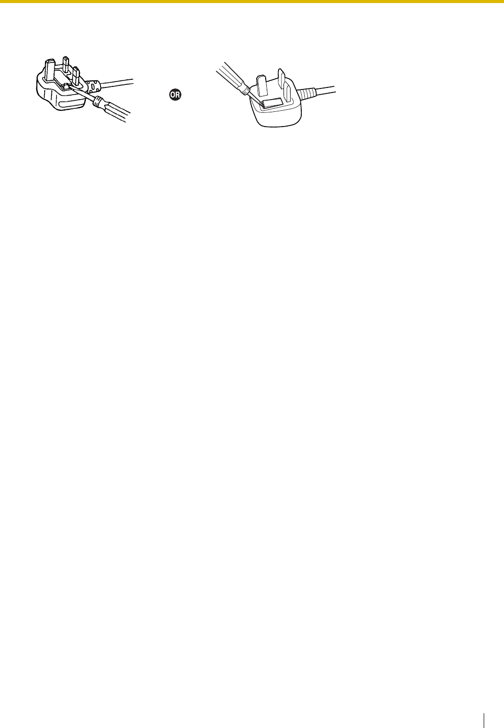
FOR YOUR SAFETY, PLEASE READ THE FOLLOWING TEXT CAREFULLY.
This appliance is supplied with a moulded three-pin mains plug for your safety and convenience. A 5 amp
fuse is fitted in this plug. Should the fuse need to be replaced, please ensure that the replacement fuse has
a rating of 5 amps and that it is approved by ASTA or BSI to BS1362.
Check for the ASTA mark or the BSI mark on the body of the fuse.
If the plug contains a removable fuse cover, you must ensure that it is refitted when the fuse is replaced. If
you lose the fuse cover, the plug must not be used until a replacement cover is obtained. A replacement
fuse cover can be purchased from your local Panasonic dealer.
IF THE FITTED MOULDED PLUG IS UNSUITABLE FOR THE AC OUTLET IN YOUR PREMISES, THEN
THE FUSE SHOULD BE REMOVED AND THE PLUG CUT OFF AND DISPOSED OF SAFELY. THERE IS
A DANGER OF SEVERE ELECTRICAL SHOCK IF THE CUT-OFF PLUG IS INSERTED INTO ANY 13 AMP
SOCKET.
If a new plug is to be fitted, please observe the wiring code as shown below. If in any doubt, please consult
a qualified electrician.
WARNING
THIS APPLIANCE MUST BE EARTHED.
IMPORTANT: The wires in the mains lead are coloured as follows:
Green-and-yellow: Earth
Blue: Neutral
Brown: Live
As the colours of the wires in the mains lead of this apparatus may not correspond with the coloured
markings identifying the terminals in your plug, proceed as follows.
The wire that is coloured GREEN-AND-YELLOW must be connected to the terminal in the plug that is
marked with the letter E or by the safety earth symbol or coloured GREEN or GREEN-AND-YELLOW.
The wire that is coloured BLUE must be connected to the terminal that is marked with the letter N or
coloured BLACK.
The wire that is coloured BROWN must be connected to the terminal that is marked with the letter L or
coloured RED.
Installation Manual 13
How to replace the fuse: Open the fuse compartment with a screwdriver and replace the fuse and fuse
cover.
The equipment must be connected to direct extension lines, and a payphone should not be connected as
an extension.
999 and 112 can be dialled on the apparatus after accessing the Exchange line for the purpose of making
outgoing calls to the BT emergency services.
During dialling, this apparatus may tinkle the bells of other telephones using the same line. This is not a fault
and we advise you not to call the Fault Repair Service.

14 Installation Manual
Table of Contents
1 System Outline ..................................................................................... 17
1.1 System Highlights........................................................................................................... 18
1.1.1 System Highlights .............................................................................................................18
1.2 Basic System Construction ...........................................................................................20
1.2.1 Basic Shelf ........................................................................................................................20
1.2.2 System Connection Diagram ............................................................................................21
1.3 Optional Equipment........................................................................................................23
1.3.1 Optional Equipment ..........................................................................................................23
1.4 Specifications..................................................................................................................26
1.4.1 General Description ..........................................................................................................26
1.4.2 Characteristics ..................................................................................................................28
1.4.3 System Capacity ...............................................................................................................29
2 Installation............................................................................................. 37
2.1 Before Installation...........................................................................................................38
2.1.1 Before Installation .............................................................................................................38
2.2 Installation of the Hybrid IP-PBX ...................................................................................40
2.2.1 Unpacking .........................................................................................................................40
2.2.2 Names and Locations .......................................................................................................41
2.2.3 Opening/Closing the Front Cover......................................................................................42
2.2.4 Installing/Replacing the Power Supply Unit.......................................................................44
2.2.5 Frame Earth Connection...................................................................................................48
2.2.6 Backup Battery Connection...............................................................................................49
2.2.7 Installing/Removing the Optional Service Cards...............................................................51
2.2.8 Types of Connectors .........................................................................................................56
2.2.9 Attaching a Ferrite Core ....................................................................................................58
2.2.10 Fastening Amphenol Connector........................................................................................60
2.2.11 Wall Mounting (KX-TDA200) .............................................................................................62
2.2.12 Wall Mounting (KX-TDA100) .............................................................................................64
2.2.13 Floor Standing (KX-TDA200 Only)....................................................................................66
2.2.14 Surge Protector Installation...............................................................................................68
2.3 Information about the Main Processing Card...............................................................71
2.3.1 MPR Card .........................................................................................................................71
2.3.2 MEC Card (KX-TDA0105).................................................................................................73
2.3.3 RMT Card (KX-TDA0196) .................................................................................................74
2.4 Information about the Trunk Cards ...............................................................................75
2.4.1 LCOT4 Card (KX-TDA0183), LCOT8 Card (KX-TDA0180), and LCOT16 Card (KX-
TDA0181)..........................................................................................................................75
2.4.2 DID8 Card (KX-TDA0182).................................................................................................77
2.4.3 CID/PAY8 Card (KX-TDA0189) .........................................................................................79
2.4.4 CID8 Card (KX-TDA0193).................................................................................................80
2.4.5 E&M8 Card (KX-TDA0184) ...............................................................................................81
2.4.6 T1 Card (KX-TDA0187).....................................................................................................84
2.4.7 E1 Card (KX-TDA0188) ....................................................................................................87
2.4.8 BRI4 Card (KX-TDA0284) and BRI8 Card (KX-TDA0288)................................................90
2.4.9 PRI30 Card (KX-TDA0290CE/CJ) ....................................................................................94
2.4.10 PRI23 Card (KX-TDA0290)...............................................................................................98

Installation Manual 15
2.4.11 IP-GW4 Card (KX-TDA0480) ......................................................................................... 101
2.4.12 IP-GW4E Card (KX-TDA0484) ....................................................................................... 103
2.4.13 IP-GW16 Card (KX-TDA0490) ....................................................................................... 105
2.5 Information about the Extension Cards ..................................................................... 107
2.5.1 CSIF4 Card (KX-TDA0143) and CSIF8 Card (KX-TDA0144)......................................... 107
2.5.2 DHLC8 Card (KX-TDA0170) .......................................................................................... 109
2.5.3 DLC8 Card (KX-TDA0171) ............................................................................................. 112
2.5.4 DLC16 Card (KX-TDA0172) ........................................................................................... 114
2.5.5 SLC8 Card (KX-TDA0173) ............................................................................................. 116
2.5.6 EXT-CID Card (KX-TDA0168) ........................................................................................ 118
2.5.7 SLC16 Card (KX-TDA0174) and MSLC16 Card (KX-TDA0175) .................................... 119
2.5.8 IP-EXT16 Card (KX-TDA0470)....................................................................................... 121
2.6 Information about the Other Cards............................................................................. 123
2.6.1 OPB3 Card (KX-TDA0190)............................................................................................. 123
2.6.2 DPH4 Card (KX-TDA0161)............................................................................................. 124
2.6.3 DPH2 Card (KX-TDA0162)............................................................................................. 126
2.6.4 EIO4 Card (KX-TDA0164).............................................................................................. 129
2.6.5 ECHO16 Card (KX-TDA0166)........................................................................................ 132
2.6.6 MSG4 Card (KX-TDA0191) ............................................................................................ 133
2.6.7 CTI-LINK Card (KX-TDA0410) ....................................................................................... 134
2.7 Connection of Extensions ........................................................................................... 136
2.7.1 Maximum Cabling Distances of the Extension Wiring (Twisted Cable) .......................... 136
2.7.2 Parallel Connection of the Extensions............................................................................ 137
2.7.3 Digital EXtra Device Port (Digital XDP) Connection ....................................................... 139
2.7.4 First Party Call Control CTI Connection ......................................................................... 144
2.8 Connection of DECT Portable Stations ...................................................................... 145
2.8.1 Overview......................................................................................................................... 145
2.8.2 Procedure Overview ....................................................................................................... 147
2.8.3 Site Planning .................................................................................................................. 149
2.8.4 Before Site Survey.......................................................................................................... 153
2.8.5 Site Survey Using the KX-TCA255/KX-TD7590............................................................. 157
2.8.6 After Site Survey............................................................................................................. 161
2.8.7 Connecting a Cell Station to the Hybrid IP-PBX............................................................. 162
2.8.8 Wall Mounting................................................................................................................. 171
2.9 Connection of 2.4 GHz Portable Stations................................................................... 173
2.9.1 Overview......................................................................................................................... 173
2.9.2 Procedure Overview ....................................................................................................... 175
2.9.3 Site Planning .................................................................................................................. 177
2.9.4 Before Site Survey.......................................................................................................... 181
2.9.5 Site Survey ..................................................................................................................... 183
2.9.6 After Site Survey............................................................................................................. 187
2.9.7 Connecting a Cell Station to the Hybrid IP-PBX............................................................. 188
2.9.8 Wall Mounting................................................................................................................. 196
2.10
Connection of Doorphones, Door Openers, External Sensors, and External Relays
.......... 198
2.10.1
Connection of Doorphones, Door Openers, External Sensors, and External Relays
........... 198
2.11 Connection of Peripherals........................................................................................... 201
2.11.1 Connection of Peripherals .............................................................................................. 201
2.12 Power Failure Connections ......................................................................................... 205
2.12.1 Power Failure Connections............................................................................................. 205
2.13 Starting the Hybrid IP-PBX .......................................................................................... 209

16 Installation Manual
2.13.1 Starting the Hybrid IP-PBX ............................................................................................. 209
3 Guide for the KX-TDA Maintenance Console ................................... 211
3.1 Overview ........................................................................................................................212
3.1.1 Overview .........................................................................................................................212
3.2 Connection ....................................................................................................................213
3.2.1 Connection ......................................................................................................................213
3.3 Installation of the KX-TDA Maintenance Console......................................................215
3.3.1 Installing and Starting the KX-TDA Maintenance Console..............................................215
4 Troubleshooting.................................................................................. 219
4.1 Troubleshooting ............................................................................................................220
4.1.1 Installation .......................................................................................................................220
4.1.2 Connection ......................................................................................................................222
4.1.3 Operation ........................................................................................................................224
4.1.4 Using the Reset Button ...................................................................................................226
4.1.5 Troubleshooting by Error Log ..........................................................................................227
5 Appendix ............................................................................................. 239
5.1 Revision History............................................................................................................240
5.1.1 PMPR Software File Version 1.1xxx ...............................................................................240
5.1.2 PMPR Software File Version 2.0xxx ...............................................................................241
5.1.3 PMPR Software File Version 3.0xxx ...............................................................................242
Index .......................................................................................................... 243

Installation Manual 17
Section 1
System Outline
This section provides general information on the Hybrid IP-
PBX, including the system capacity and specifications.

1.1 System Highlights
18 Installation Manual
1.1 System Highlights
1.1.1 System Highlights
Networking Features
This Hybrid IP-PBX supports the following networking features:
TIE Line Service
A TIE line is a privately leased communication line between 2 or more PBXs, which provides cost
effective communications between company members at different locations.
Virtual Private Network (VPN)
VPN is a service provided by the telephone company. It uses an existing line as if it were a private line.
QSIG Network
QSIG is a protocol which is based on ISDN (Q.931) and offers enhanced PBX features in a private
network.
Voice over Internet Protocol (VoIP) Network
The PBX can connect to another PBX via a private IP network. In this case, voice signals are converted
into IP packets and sent through this network.
Built-in Small Call Centre Features
An incoming call distribution group can be used as a small call centre with the following features:
Queuing Feature
When a preprogrammed number of extensions in an incoming call distribution group are busy,
additional incoming calls can wait in a queue. While calls are waiting in the queue, the calls are handled
by the Queuing Time Table, which can be assigned for each time mode (day/lunch/break/night).
Log-in/Log-out
Incoming call distribution group members can join (Log-in) or leave (Log-out) the groups manually.
While logged-in, a member extension can have a preprogrammed time period automatically for refusing
calls after completing the last call (Wrap-up).
VIP Call
It is possible to assign a priority to incoming call distribution groups. If an extension belongs to multiple
groups and the extension becomes idle, queuing calls in the groups will be distributed to the extension
in priority order.
Computer Telephony Integration (CTI) Features
Connecting a PC to a DPT, or connecting a CTI server to this Hybrid IP-PBX allows function of the PC, PBX
and extension to be integrated so that, for example, detailed caller information can be taken from a database
and displayed on the PC as a call arrives, or the PC can dial numbers for the extension automatically.
Voice Mail Features
This Hybrid IP-PBX supports Voice Processing Systems (VPS) with DTMF Integration as well as DPT
(Digital) Integration.
Parallelled Telephone Features
By connecting telephones in parallel, you can increase the number of telephones connected to the PBX
without adding additional extension cards.

1.1 System Highlights
Installation Manual 19
Parallel Mode
An SLT can be connected to an APT or DPT which is connected to a Super Hybrid Port of the PBX. The
SLT shares the same extension number with the APT or DPT.
EXtra Device Port (XDP) Mode
An SLT can be connected to a DPT which is connected to a Super Hybrid Port of the PBX. Unlike
parallel mode, XDP mode allows each telephone to act as an independent extension with its own
extension number.
Digital XDP
A DPT can be connected to another DPT which is connected to a DPT port or a Super Hybrid Port of
the PBX. Similar to XDP mode, each DPT acts as an independent extension with its own extension
number.
Portable Station (PS) Features
PSs can be connected to this Hybrid IP-PBX. It is possible to use the Hybrid IP-PBX features using the PS
like a PT. A PS can also be used in parallel with a wired telephone (Wireless XDP Parallel Mode). In this
case, the wired telephone is the main telephone and the PS is the sub telephone.
PC Phone/PC Console Features
This Hybrid IP-PBX supports PC Phone and PC Console. These Panasonic CTI applications provide
advanced features combining telephone and PC, such as the ability to display detailed caller information,
including a photograph, on the screen of the PC when a call is received, or to dial a telephone number
automatically just by selecting a name.
Hospitality Features
This Hybrid IP-PBX has several features that support its use in a hotel-type environment. Extensions
corresponding to guest rooms can be "checked in" or "checked out" by a designated hotel operator, who can
also check or set wake-up calls, and print out records of guest charges.
1.2 Basic System Construction
20 Installation Manual
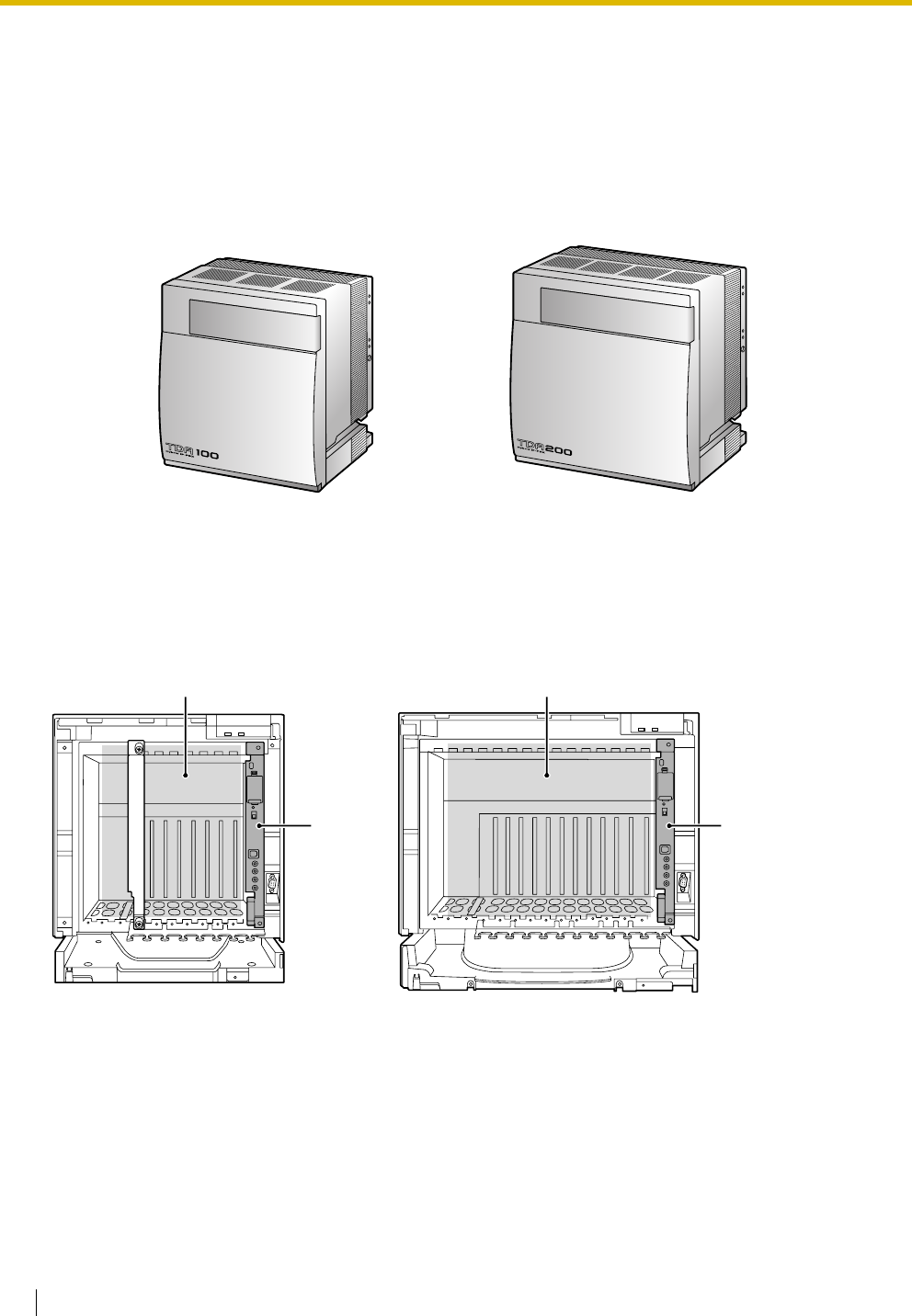
1.2 Basic System Construction
1.2.1 Basic Shelf
The basic shelf contains an MPR card for controlling the Hybrid IP-PBX. To use the system, install a power
supply unit (PSU) in the PSU Slot and optional service cards in the basic shelf.
Construction of the Basic Shelf
KX-TDA100 KX-TDA200
B B
A A
A: Slots for Expansion
B: MPR Card
1.2 Basic System Construction
Installation Manual 21
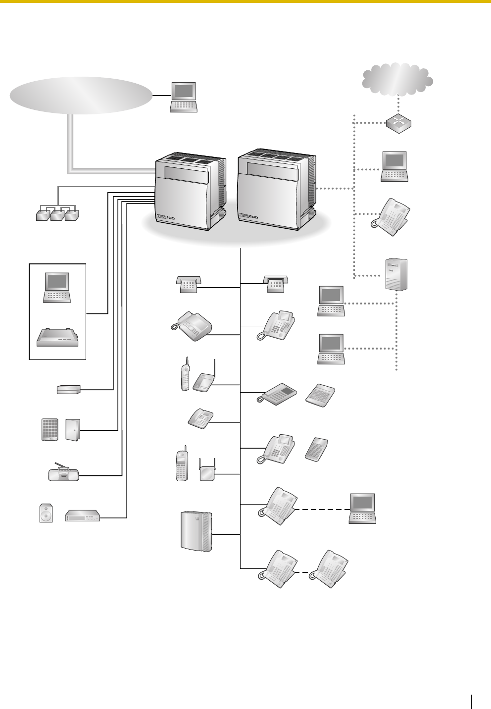
1.2.2 System Connection Diagram
Doorphone & Door Opener
BGM/Music On Hold (MOH)
Pager/
Speaker
Batteries
Voice Processing
System
KX-T7636/
KX-T7633
Remote PC
PC
Printer
Router
Private
IP Network
Trunk (Telephone Company Lines)
Analogue/BRI/PRI/T1/E1
Hybrid IP-PBX
PC
SLT
CSPS
Wireless Phone
Fax Machine
PC
USB
APT
DPT
ISDN Telephone
Amplifier
CTI Server
PC
PC
SLT
DPT
DSS Console
DSS Console
KX-T7600 DPT KX-T7600 DPT
External Sensor/
External Relay Device
IP-PT
1.2 Basic System Construction
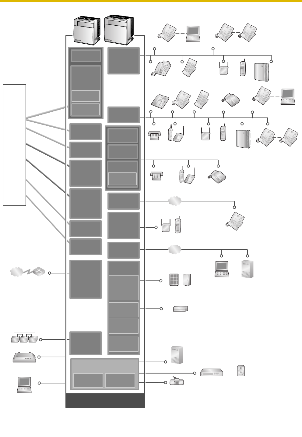
22 Installation Manual
SLT Wireless Phone
Fax Machine
CS PS
PC
KX-T7636/
KX-T7633
DSS Console
Doorphone & Door Opener
PT-interface CS PS
Private
IP Network
Station Message
Detail Recording (SMDR)
PC
Router
ISDN BRI Line
ISDN BRI Line
(Digital Trunk)
(Digital Trunk)
ISDN BRI Line
(Digital Trunk)
ISDN PRI Line
ISDN PRI Line
(Digital Trunk)
(Digital Trunk)
ISDN PRI Line
(Digital Trunk)
T1 Line
T1 Line
(Digital Trunk)
(Digital Trunk)
T1 Line
(Digital Trunk)
Analogue
Analogue
Trunk
Trunk
Analogue
Trunk
E & M Line
E & M Line
E & M Line
E1 Line
E1 Line
(Digital Trunk)
(Digital Trunk)
E1 Line
(Digital Trunk)
Telephone
Company
SLT Wireless Phone Fax Machine
Hybrid IP-PBX
Mountable Equipment
DPT
APT DPT DSS Console
PT-interface CS PS
Voice
Processing
System
Batteries
Radio
Amplifier Pager/Speaker
CTI Server
PC
LAN
CTI Server
LCOT16
(KX-TDA0181)
LCOT8
(KX-TDA0180)
DLC16
(KX-TDA0172)
DLC8
(KX-TDA0171)
DHLC8
(KX-TDA0170)
CSIF4
(KX-TDA0143)
CSIF8
(KX-TDA0144)
CTI-LINK
(KX-TDA0410)
OPB3
(KX-TDA0190)
E1
(KX-TDA0188)
IP-GW4
(KX-TDA0480)
IP-GW4E
(KX-TDA0484)
IP-GW16
(KX-TDA0490)
PRI30
(KX-TDA0290
CE/CJ)
PRI23
(KX-TDA0290)
BRI4
(KX-TDA0284)
BRI8
(KX-TDA0288)
T1
(KX-TDA0187)
E&M8
(KX-TDA0184)
DID8
(KX-TDA0182)
PSU-S/M/L
(KX-TDA0108/
KX-TDA0104/
KX-TDA0103)
DPH4
(KX-TDA0161)
DPH2
(KX-TDA0162)
MPR
(Installed by default)
RMT
(KX-TDA0196)
MEC
(KX-TDA0105)
LCOT4
(KX-TDA0183)
IP-EXT16
(KX-TDA0470)
IP-PT
ECHO16
(KX-TDA0166)
MSG4
(KX-TDA0191)
EIO4
(KX-TDA0164)
External Sensor/External Relay Device
MSLC16
(KX-TDA0175)
SLC8
(KX-TDA0173)
EXT-CID
(KX-TDA0168)
SLC16
(KX-TDA0174)
LAN
Voice
Processing
System
KX-T7600
DPT KX-T7600
DPT
PC
KX-T7636/
KX-T7633
KX-T7600
DPT KX-T7600
DPT
LCOT4
(KX-TDA0183)
LCOT16
(KX-TDA0181)
LCOT8
(KX-TDA0180)
CID/PAY8
(KX-TDA0189)
CID8
(KX-TDA0193)

1.3 Optional Equipment
Installation Manual 23
1.3 Optional Equipment
1.3.1 Optional Equipment
Model No. Model Name Description
KX-TDA0103 L-Type Power Supply Unit (PSU-L) Power Supply Unit for KX-TDA200. Total power
output of 279 W. Safety Class 1 compliant.
KX-TDA0104 M-Type Power Supply Unit (PSU-M) Power Supply Unit for KX-TDA100 and KX-TDA200.
Total power output of 140.4 W. Safety Class 1
compliant.
KX-TDA0105 Memory Expansion Card (MEC) Memory expansion card to increase system data
storage space, enable Broadcasting and Call Billing
for Guest Room features, and double the number of
DPTs, using Digital XDP connection. To be mounted
on the MPR card.
KX-TDA0108 S-Type Power Supply Unit (PSU-S) Power Supply Unit for KX-TDA100. Total power
output of 74 W. Safety Class 1 compliant.
KX-TDA0143 4 Cell Station Interface Card (CSIF4) 4-port CS interface card for 4 CSs.
KX-TDA0144 8 Cell Station Interface Card (CSIF8) 8-port CS interface card for 8 CSs.
KX-TDA0161 4-Port Doorphone Card (DPH4) 4-port doorphone card for 4 doorphones and 4 door
openers. To be mounted on the OPB3 card.
KX-TDA0162 2-Port Doorphone Card (German
Type) (DPH2)
2-port doorphone card for 2 German-type
doorphones and 2 door openers. To be mounted on
the OPB3 card.
KX-TDA0164 4-Port External Input/Output Card
(EIO4)
4-port external input/output card. To be mounted on
the OPB3 card.
KX-TDA0166 16-Channel Echo Canceller Card
(ECHO16)
16-channel card for echo cancellation during
conferences. To be mounted on the OPB3 card.
KX-TDA0168 Extension Caller ID Card (EXT-CID) Sends Caller ID signals to extension ports. To be
mounted on the SLC8 card only.
KX-TDA0170 8-Port Digital Hybrid Extension Card
(DHLC8)
8-port digital hybrid extension card for DPTs, APTs,
SLTs, DSS consoles, and PT-interface CSs, with 2
power failure transfer (PFT) ports.
KX-TDA0171 8-Port Digital Extension Card (DLC8) 8-port digital extension card for DPTs, DSS
consoles, and PT-interface CSs.
KX-TDA0172 16-Port Digital Extension Card
(DLC16)
16-port digital extension card for DPTs, DSS
consoles, and PT-interface CSs.
KX-TDA0173 8-Port Single Line Telephone
Extension Card (SLC8)
8-port extension card for SLTs with 2 power failure
transfer (PFT) ports.
KX-TDA0174 16-Port Single Line Telephone
Extension Card (SLC16)
16-port extension card for SLTs with 4 power failure
transfer (PFT) ports.

1.3 Optional Equipment
24 Installation Manual
KX-TDA0175 16-Port Single Line Telephone
Extension with Message Lamp Card
(MSLC16)
16-port extension card for SLTs with Message
Waiting Lamp control and 4 power failure transfer
(PFT) ports. Maximum power output of 160 V/90 V
for Message Waiting Lamp control.
KX-TDA0180 8-Port Analogue Trunk Card (LCOT8) 8-port analogue trunk card with 2 power failure
transfer (PFT) ports.
KX-TDA0181 16-Port Analogue Trunk Card
(LCOT16)
16-port analogue trunk card with 4 power failure
transfer (PFT) ports.
KX-TDA0182 8-Port DID Card (DID8) 8-port DID trunk card.
KX-TDA0183 4-Port Analogue Trunk Card (LCOT4) 4-port analogue trunk card with 2 power failure
transfer (PFT) ports.
KX-TDA0184 8-Port E & M Trunk Card (E&M8) 8-port E & M (TIE) trunk card. Type 5 support.
KX-TDA0187 T-1 Trunk Card (T1) 1-port T1 trunk card. EIA/TIA standard compliant.
KX-TDA0188 E-1 Trunk Card (E1) 1-port E1 trunk card. ITU-T standard compliant.
KX-TDA0189 8-Port Caller ID/Pay Tone Card (CID/
PAY 8)
8-port Caller ID signal type FSK/FSK (with Call
Waiting Caller ID [Visual Caller ID])/DTMF, and 8-
port Pay Tone Service (12 kHz/16 kHz). To be
mounted on the LCOT8/LCOT16 cards.
KX-TDA0190 Optional 3-Slot Base Card (OPB3) Optional 3-slot base card for mounting a maximum
of 3 option cards from the following: MSG4, DPH4,
DPH2, or ECHO16 card.
KX-TDA0191 4-Channel Message Card (MSG4) 4-channel message card. To be mounted on the
OPB3 card.
KX-TDA0193 8-Port Caller ID Card (CID8) 8-port Caller ID signal type FSK/FSK (with Call
Waiting Caller ID [Visual Caller ID])/DTMF. To be
mounted on the LCOT8/LCOT16 cards.
KX-TDA0196 Remote Card (RMT) Analogue modem card for remote communication
with the Hybrid IP-PBX. ITU-T V.90 support. To be
mounted on the MPR card.
KX-TDA0284 4-Port BRI Card (BRI4) 4-port ISDN Basic Rate Interface card with 1 power
failure transfer port. EURO-ISDN/ETSI compliant.
KX-TDA0288 8-Port BRI Card (BRI8) 8-port ISDN Basic Rate Interface card with 1 power
failure transfer port. EURO-ISDN/ETSI compliant.
KX-TDA0290CE/CJ PRI Card (PRI30) 1-port ISDN Primary Rate Interface card (30B
channels). EURO-ISDN/ETSI compliant.
KX-TDA0290 PRI Card (PRI23) 1-port ISDN Primary Rate Interface card (23B
channels). NI (North American standard ISDN
protocol) compliant.
KX-TDA0410 CTI Link Card (CTI-LINK) Ethernet card for CTI communication via 10BASE-T
port. CSTA Phase 3 protocol compatible.
KX-TDA0470 16-Channel VoIP Extension Card (IP-
EXT16)
16-channel VoIP extension card. Compliant with
Panasonic proprietary protocol, and ITU-T G.729a
and G.711 CODEC methods.
Model No. Model Name Description

1.3 Optional Equipment
Installation Manual 25
Note
For the maximum number of optional service cards that can be installed in the Hybrid IP-PBX, refer to
"1.4.3 System Capacity".
KX-TDA0480 4-Channel VoIP Gateway Card (IP-
GW4)
4-channel VoIP gateway card. Compliant with VoIP
H.323 V.2 protocol, and ITU-T G.729a and G.723.1
CODEC methods. G3 fax support.
KX-TDA0484 4-Channel VoIP Gateway Card (IP-
GW4E)
4-channel VoIP gateway card. Compliant with VoIP
H.323 V.2 protocol, and ITU-T G.729a, G.723.1, and
G.711 CODEC methods.
KX-TDA0490 16-Channel VoIP Gateway Card (IP-
GW16)
16-channel VoIP gateway card. Compliant with VoIP
H.323 V.2 protocol, and ITU-T G.729a, G.723.1, and
G.711 CODEC methods.
KX-TDA0820 SD Memory Card for Software
Upgrade
Optional SD Memory Card to upgrade PMPR file
version 1.xxxx Hybrid IP-PBX. For more details,
refer to the SD Memory Card Installation/Upgrade
Guide.
KX-TDA0920 SD Memory Card for Software
Upgrade to Enhanced Version
Optional SD Memory Card to use enhanced
features. For more details, refer to the SD Memory
Card Installation/Upgrade Guide.
Model No. Model Name Description

1.4 Specifications
26 Installation Manual
1.4 Specifications
1.4.1 General Description
Control Bus Original bus (16-bit, 8 MHz, 10 megabytes per second)
Communication Bus H.100 bus conformity (1024 time slots)
Switching Non-blocking
Power Input PSU-S 100 V AC to 130 V AC, 1.4 A/200 V AC to 240 V AC, 0.8 A,
50 Hz/60 Hz
PSU-M 100 V AC to 130 V AC, 2.5 A/200 V AC to 240 V AC, 1.4 A,
50 Hz/60 Hz
PSU-L 100 V AC to 130 V AC, 5.1 A/200 V AC to 240 V AC, 2.55 A,
50 Hz/60 Hz
External Battery +36 V DC (+12 V DC × 3, recommended maximum capacity
is 28 Ah)
Maximum Power Failure Tolerance 300 ms (without using backup batteries)
Memory Backup Duration 7 years
Dialling Trunk Dial Pulse (DP) 10 pps, 20 pps
Tone (DTMF) Dialling
Extension Dial Pulse (DP) 10 pps, 20 pps
Tone (DTMF) Dialling
Mode Conversion DP-DTMF, DTMF-DP
Ring Frequency 20 Hz/25 Hz (selectable)
Trunk Loop Limit 1600 Ω maximum
Operating
Environment
Temperature 0 to 40
Humidity 10 % to 90 % (non-condensing)
Conference Call Trunk From 10 × 3-party conference call to 4 × 8-party conference
call
Music on Hold (MOH) 2 ports (Level Control: -11 dB to +11 dB in 1 dB steps)
MOH1: External Music Source port
MOH2: Selectable Internal/External Music Source port
Paging Internal Level Control: -15 dB to +6 dB in 3 dB steps
External 2 ports (Volume Control: -15 dB to +15 dB in 1 dB steps)
Serial Interface Port RS-232C 1 (maximum 115.2 kbps)
USB 1
˚
C
˚
C

1.4 Specifications
Installation Manual 27
Extension Connection Cable SLT 1-pair wire (T, R)
DPT 1-pair wire (D1, D2) or
2-pair wire (T, R, D1, D2)
APT 2-pair wire (T, R, D1, D2)
PT-interface CS 1-pair wire (D1, D2)
DSS Console and Add-on
Key Module
1-pair wire (D1, D2)
Dimension KX-TDA100 334 mm (W) × 390 mm (H) × 270 mm (D)
KX-TDA200 430 mm (W) × 415 mm (H) × 270 mm (D)
Weight (when fully
mounted)
KX-TDA100 Under 12 kg
KX-TDA200 Under 16 kg

1.4 Specifications
28 Installation Manual
1.4.2 Characteristics
Terminal Equipment Loop Limit • PT: KX-T7600 series DPT: 90 Ω; all other DPTs/APTs: 40 Ω
• SLT: 600 Ω including set
• Doorphone: 20 Ω
• CS: 130 Ω; PT-interface CS: 65 Ω
Minimum Leakage Resistance 15 000 Ω minimum
Maximum Number of Extension
Instruments per Line
1for PT or SLT
2by Parallel or eXtra Device Port connection of an APT/DPT and an SLT
3by Digital eXtra Device Port connection of 2 DPTs and an SLT
Ring Voltage 75 Vrms at 20 Hz/25 Hz depending on the Ringing Load
Trunk Loop Limit 1600 Ω maximum
Hookswitch Flash/Recall Timing
Range
24 ms to 2032 ms
BRI Cards Internal ISDN Mode Supply Voltage: 40 V
Power Supply (BRI4): 4.5 W per 1 line, 10 W per 4 lines
Power Supply (BRI8): 4.5 W per 1 line, 20 W per 8 lines
Power Supply Method: Phantom Power Supply
Door Opener Current Limit 24 V DC/30 V AC, 1 A maximum
External Relay Current Limit 24 V DC/30 V AC, 1 A maximum
External Sensor Current Limit Power to the external sensor is provided from the EIO4 card and must be
grounded through the EIO4 card. For the connection diagram, refer to
"2.6.4 EIO4 Card (KX-TDA0164)". The Hybrid IP-PBX detects input from
the sensor when the signal is under 100 Ω.
Paging Terminal Impedance 600 Ω
MOH (Music on Hold) Terminal
Impedance
10 000 Ω
1.4 Specifications
Installation Manual 29
1.4.3 System Capacity
Maximum Optional Service Cards
There are 2 types of optional service cards for installation:
• Cards installed in the slots of the Hybrid IP-PBX
• Cards mounted on other optional service cards
Notes
• Any card that exceeds the capacity of the Hybrid IP-PBX will be ignored.
• When the Hybrid IP-PBX starts up with an invalid configuration, some cards will be ignored.
Cards Installed in the Slots of the Hybrid IP-PBX
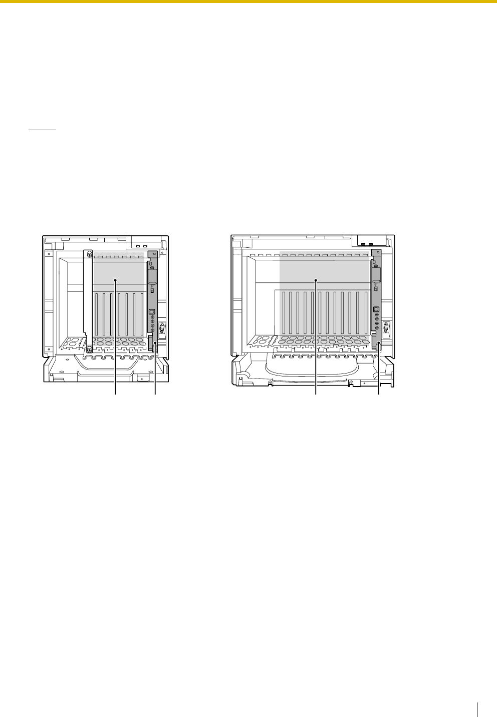
A. Free Slots 1 to 6 (from the left)
B. MPR Card Slot
C. Free Slots 1 to 11 (from the left)
KX-TDA100 KX-TDA200
AB C B

1.4 Specifications
30 Installation Manual
The following number of optional service cards can be installed in the various slots of the Hybrid IP-PBX.
Card Type Maximum Number Installed in
KX-TDA100 KX-TDA200
MPR 1 1 MPR Card Slot
Trunk Card Tot al 6*1 To t al 8 *2
Free Slot
LCOT4
68
LCOT8
LCOT16
DID8
E&M8
BRI4
BRI8
T1
44
E1
PRI23
PRI30
IP-GW4
44
IP-GW4E
IP-GW16
1.4 Specifications
Installation Manual 31
Cards Mounted on Other Optional Service Cards
The following number of optional service cards can be mounted on the specified other optional service
cards.
Extension Card Total 6 Total 8
Free Slot
DHLC8
68
DLC8
DLC16
SLC8
SLC16
MSLC16
IP-EXT16
CSIF4
44
CSIF8
OPB3 4 4
CTI-LINK 1 1
*1 When installing T1, E1, PRI30, PRI23, or IP-GW4 cards, make sure that the number of these cards × 2 + the number of other cards
(including IP-GW4E cards) does not exceed 8.
*2 One T1, E1, PRI30, PRI23, or IP-GW4 card counts as 2 cards. However, one IP-GW4E card counts as 1 card.
Card Type Maximum Number Mounted on
KX-TDA100 KX-TDA200
MEC 1 1 MPR Card
RMT 1 1
CID/PAY8 12 16 LCOT8 Card/LCOT16 Card
CID8
EXT-CID 6 8 SLC8 Card
DPH4 4 4
OPB3 Card
DPH2 8 8
ECHO16 2*1
*1 Only 1 ECHO16 card can be mounted on each OPB3 card.
2*1
MSG4 4 4
EIO4 4 4
Card Type Maximum Number Installed in
KX-TDA100 KX-TDA200

1.4 Specifications
32 Installation Manual
Maximum Terminal Equipment
The following number of items of terminal equipment can be supported by the Hybrid IP-PBX. For how to
count the total number of items of equipment to be connected, refer to "MEC Card Calculation".
Terminal Equipment Type KX-TDA100 KX-TDA200
Without MEC
Card
With MEC
Card
Without MEC
Card
With MEC
Card
Telephone 64 160 128 256
SLT 64 96 128 128
KX-T7600 series DPT 64 128 128 256
KX-T7560/KX-T7565 DPT 64 96 128 128
Other DPT 32 32 128 128
APT 24246464
IP-PT 64 96 128 128
DSS console 8 8
CS 32 32
PS 128 128
Voice Processing System (VPS) 2 2
Doorphone 16 16
Door Opener 16 16
External Sensor 16 16
External Relay 16 16
1.4 Specifications
Installation Manual 33
MEC Card Calculation
Calculate the MEC figure from the type and total number of items of equipment to be connected. If the MEC
figure exceeds 64 (for KX-TDA100) or 128 (for KX-TDA200), you need to install an MEC card.
MEC Card Calculation
Calculation Example (KX-TDA100)
The total MEC figure is 88. As this exceeds 64, you need to install an MEC card for this configuration.
Equipment Type MEC Figure
PT KX-T7600 series DPT/KX-T7600 series DSS
console
1
KX-T7560/KX-T7565 DPT 1
Other DPT/Other DSS console 1
APT 1
IP-PT 1
Extension Card*1
*1 Only the extension cards that can support SLTs count for the MEC figures.
DHLC8 8
SLC8 8
SLC16 16
MSLC16 16
CS (1 unit) 0
PT-interface CS (1 unit) 0
ISDN Extension 0
VPS (1 port) 1
Equipment Type MEC Figure
KX-T7600 series DPT 48 units 48
SLC16 1 card 16
MSLC16 1 card 16
VPS 8 ports 8
To t a l 88
1.4 Specifications
34 Installation Manual
Power Supply Unit Selection
The Hybrid IP-PBX needs a power supply unit (PSU) suitable for its configuration. Calculate the load figure
from the type and number of items of equipment to be connected, and determine the type of PSU that will
be required.
Load Figure Calculation
PSU Capacity
Each PSU supports a different load figure.
Equipment Type Load Figure
PT KX-T7600 series DPT/KX-T7600 series DSS
console
1
KX-T7560/KX-T7565 DPT 1
Other DPT/Other DSS console 4
APT 4
IP-PT 0
Extension Card*1
*1 Only the extension cards that can support SLTs count for the load figures.
DHLC8 8
SLC8 8
SLC16 16
MSLC16 16
CS (1 unit) 4
PT-interface CS (1 unit) 4
ISDN Extension 2
VPS (1 port) 1
PSU Type Maximum Load Figure
PSU-S*1
*1 Available for the KX-TDA100
64
PSU-M*2
*2 Available for the KX-TDA100 and KX-TDA200
128
PSU-L*3
*3 Available for the KX-TDA200
512

1.4 Specifications
Installation Manual 35
Calculation Example (KX-TDA200)
The total load figure is 96. As this is between 64 and 128, you should install the PSU-M. But if you expect
expansion in the future, it may be better to install the PSU-L. There is no harm in installing a PSU that is
larger than is required for the current configuration.
Equipment Type Load Figure
KX-T7600 series DPT 48 units 48
Other DPT 2 units 8
SLC16 1 card 16
MSLC16 1 card 16
VPS 8 ports 8
To t a l 96

1.4 Specifications
36 Installation Manual

Installation Manual 37
Section 2
Installation
This section describes the procedures to install the Hybrid IP-
PBX. Detailed instructions for planning the installation site,
installing the shelves and optional service cards, and cabling
of peripheral equipment are provided. Further information on
system expansion and peripheral equipment installation is
included.

2.1 Before Installation
38 Installation Manual
2.1 Before Installation
2.1.1 Before Installation
Please read the following notes concerning installation and connection before installing the Hybrid IP-PBX
and terminal equipment.
Be sure to comply with all applicable laws, regulations, and guidelines.
Safety Installation Instructions
When installing telephone wiring, basic safety precautions should always be followed to reduce the risk of
fire, electric shock and injury to persons, including the following:
1. Never install telephone wiring during a lightning storm.
2. Never install telephone jacks in wet locations unless the jack is specifically designed for wet locations.
3. Never touch uninsulated telephone wires or terminals unless the telephone line has been disconnected
at the network interface.
4. Use caution when installing or modifying telephone lines.
Installation Precautions
This set is made for wall mounting (KX-TDA100/KX-TDA200) or floor standing (KX-TDA200 only), and
should be installed in a location where it is accessible for inspections and maintenance.
To prevent malfunction, noise, or discolouration, avoid installing the system in the following locations:
1. In direct sunlight and hot, cold, or humid places. (Temperature range: 0 to 40 )
2. Areas where sulfuric gases may be present, such as near thermal springs.
3. Areas where shocks or vibrations are frequent or strong.
4. High-dust areas, or places the system may come into contact with water or oil.
5. Near devices that generate high frequencies, such as sewing machines or electric welders.
6. On or near computers, telexes, or other office equipment, as well as microwave ovens or air
conditioners. (It is preferable not to install the system in the same room as the above equipment.)
7. Within 1.8 m of radios and televisions. (Both the Hybrid IP-PBX and PTs should be at least 1.8 m away
from such devices).
8. Locations where other objects will obstruct the area around the Hybrid IP-PBX. Be especially careful
to leave at least 20 cm of space above and 10 cm to the sides of the Hybrid IP-PBX for ventilation.
9. Do not block the openings of the Hybrid IP-PBX.
10. Do not stack up the optional service cards.
Wiring Precautions
Be sure to follow these instructions when wiring the unit:
1. Do not run unshielded telephone cables near AC power cables, computer cables, AC power sources,
etc. When running cables near other noise-generating devices or cables, use shielded telephone
cables or shield the telephone cables with metal tubing.
2. If cables are run on the floor, use protectors to prevent the cables from being stepped on. Avoid running
cables under carpets.
3. Avoid using the same AC outlet for computers, telexes, and other office equipment, as noise generated
by such equipment may hamper system performance or interrupt the system.
˚
C
˚
C

2.1 Before Installation
Installation Manual 39
4. Use 2-pair telephone cables when connecting PTs.
Use 1-pair telephone cables when connecting SLTs, data terminals, answering machines, computers,
Voice Processing Systems, etc.
5. Unplug the system from its power source when wiring, and plug the system back in only after all wiring
is completed.
6. Mis-wiring may cause the Hybrid IP-PBX to operate improperly. Refer to Section 2 "Installation" when
wiring the system.
7. If an extension does not operate properly, disconnect the telephone from the extension line and connect
it again, or turn off the Hybrid IP-PBX using the power switch, then turn it on again.
8. For safety purposes this unit is equipped with an earthed plug. If you do not have an earthed outlet,
please have one installed. Do not bypass this safety feature by tampering with the plug.
9. Use twisted pair cable for trunk connection.
10. Trunks should be installed with surge protectors. For details, refer to "2.2.14 Surge Protector
Installation".

2.2 Installation of the Hybrid IP-PBX
40 Installation Manual
2.2 Installation of the Hybrid IP-PBX
2.2.1 Unpacking
Unpack the box and check the items below:
KX-TDA100 KX-TDA200
Main Unit 1 1
AC Cord with a Ferrite Core*1
*1 In Canada, there is no ferrite core attached to the AC cord.
1*2
*2 KX-TDA100BX/KX-TDA200BX is supplied with 2 types of AC cord. Please use whichever is appropriate for the country/area.
1*2
Metal Bracket 1 1
Screw A 3 4
Screw B (Black) 2 6
Anchor Plug 3 4
Mini Plug (for pager and music source) 4 4
SD Memory Card 1 1
2.2 Installation of the Hybrid IP-PBX
Installation Manual 41
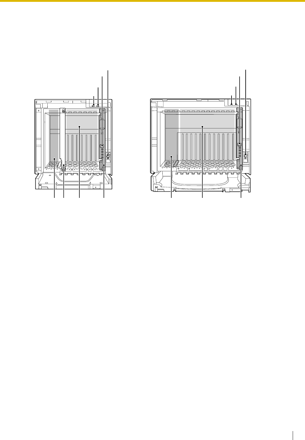
2.2.2 Names and Locations
Inside View
A. RUN Indicator
B. ALARM Indicator
C. USB Port
D. RS-232C Port
E. PSU Slot
F. Null Slot (not available for any optional service card)
G. Free Slots 1 to 6 (from the left)
H. MPR Card Slot
I. Free Slots 1 to 11 (from the left)
KX-TDA100 KX-TDA200
F
D
C
A
B
D
C
A
B
GIEEHH
2.2 Installation of the Hybrid IP-PBX
42 Installation Manual
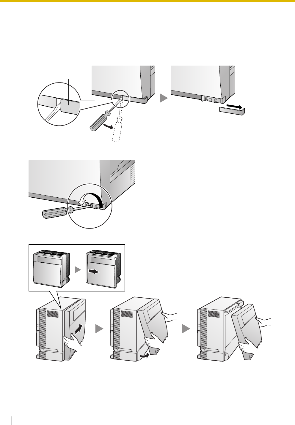
2.2.3 Opening/Closing the Front Cover
Opening the Front Cover
1. Insert a flathead screwdriver into the opening (on the left of the screw cover) and unlatch the screw
cover.
2. Turn the screw anticlockwise to loosen.
3. Slide the front cover to the right until it stops, then lift the front cover.
Screw Cover
2.2 Installation of the Hybrid IP-PBX
Installation Manual 43
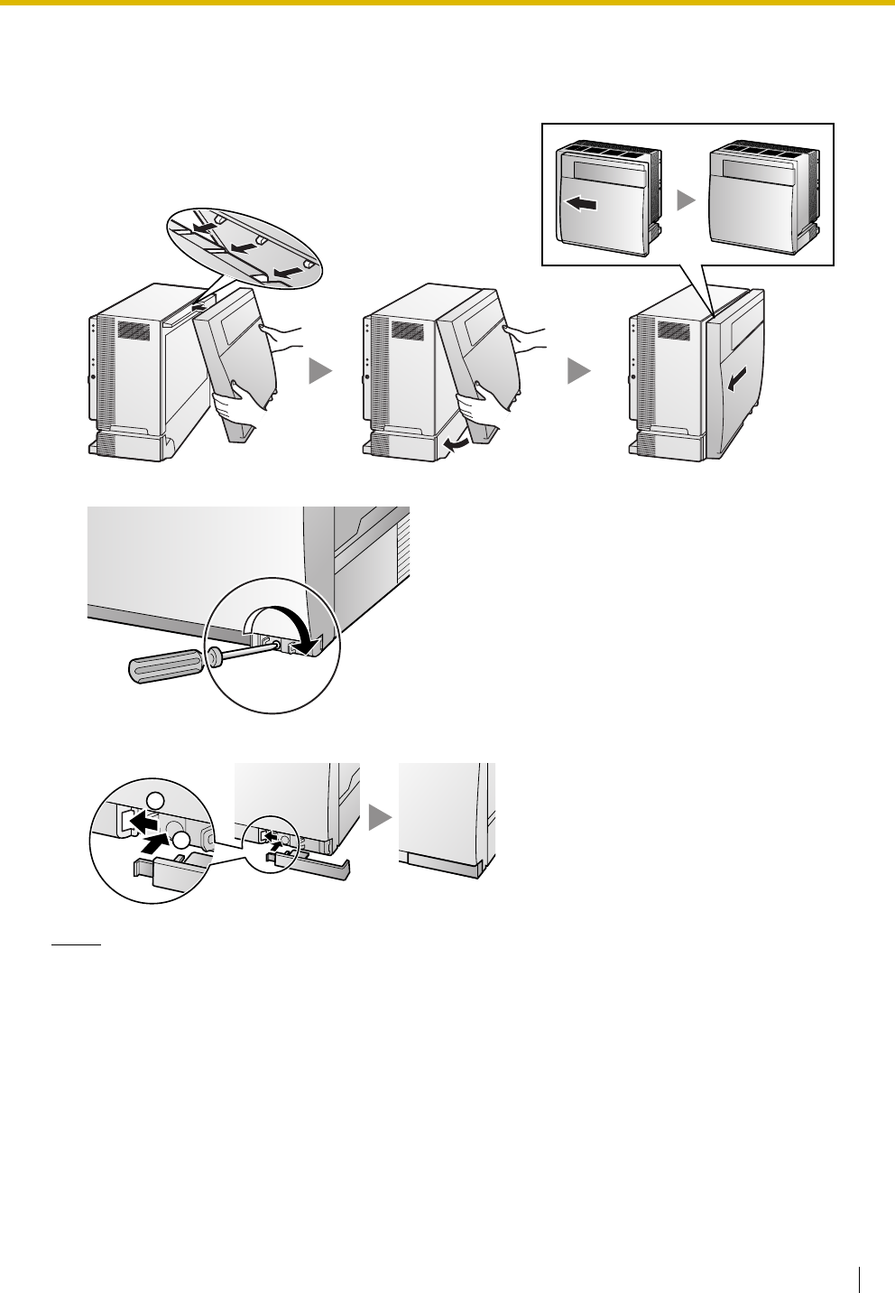
Closing the Front Cover
1. Hook the front cover onto the shelf (line up the protrusions on the cover with the receptacles on the
shelf). Then slide the front cover to the left until it locks.
2. Turn the screw clockwise to tighten.
3. Secure the screw cover.
Notes
• For safety reasons, close the front cover and tighten the screw before operating the Hybrid IP-PBX.
• Do not forget to tighten the screw before securing the screw cover.
1
2
2.2 Installation of the Hybrid IP-PBX
44 Installation Manual
2.2.4 Installing/Replacing the Power Supply Unit
Function
Accessories and User-supplied Items
Accessories (included): Screws × 4
User-supplied (not included): Earthing wire, Back-up Battery Cable (KX-A228 for PSU-S and PSU-M, or
KX-A229 for PSU-L)
Notes
• For details about frame earth connection, refer to "2.2.5 Frame Earth Connection".
• For details about backup batteries connection, refer to "2.2.6 Backup Battery Connection".
Safety Instructions
Each PSU complies with Safety Class 1 of IEC60950, EN60950, UL60950,
CAN/CSA-C22.2 No.60950, and AS/NZS60950; therefore a protective earth connection exists between the
mains outlet ground and the PSU case. To ensure the PBX chassis is safely grounded, it is essential that
the PSU case be securely fastened to the PBX chassis with the 4 screws provided with each PSU.
When installing or replacing a PSU, basic safety precautions should always be followed to reduce the risk
of fire, electric shock and injury to persons, including the following:
1. Never install or replace a PSU during a lightning storm.
2. Never install or replace a PSU in wet locations.
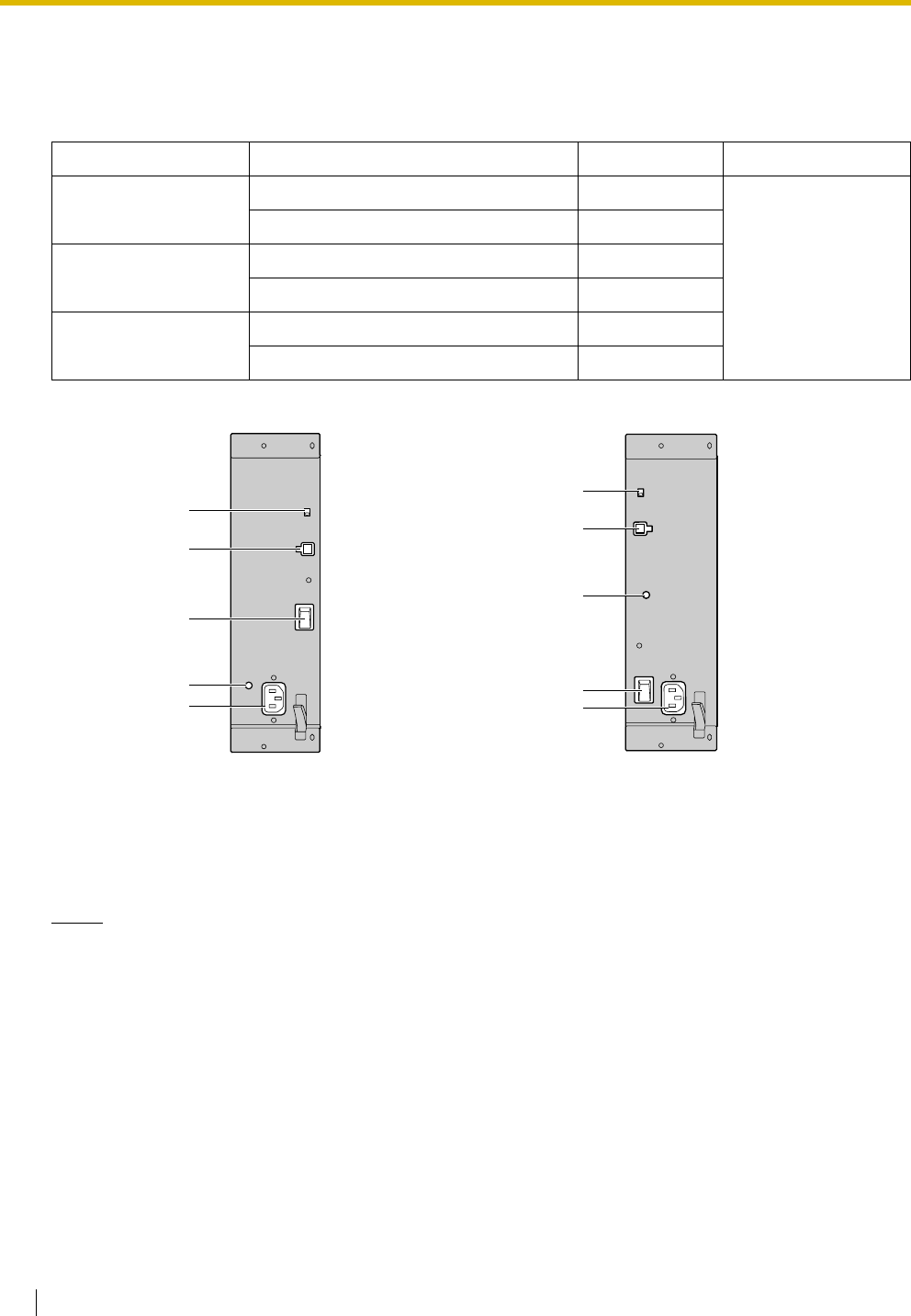
PSU Type Lower/Upper Input Voltage Range Current Input Frequency
PSU-S
(for KX-TDA100)
Lower: 100 V AC to 130 V AC 1.4 A
50 Hz or 60 Hz
Upper: 200 V AC to 240 V AC 0.8 A
PSU-M
(for KX-TDA100/200)
Lower: 100 V AC to 130 V AC 2.5 A
Upper: 200 V AC to 240 V AC 1.4 A
PSU-L
(for KX-TDA200)
Lower: 100 V AC to 130 V AC 5.1 A
Upper: 200 V AC to 240 V AC 2.55 A
AC Inlet
Power Switch
AC Inlet
Power Switch
PSU-S PSU-M/PSU-L
Battery Switch
Earth Terminal
Battery Switch
Earth Terminal
Battery Connector
Battery Connector
2.2 Installation of the Hybrid IP-PBX
Installation Manual 45
3. Never install or replace a PSU unless at least 20 s has elapsed after the AC supply and backup
battery supply are disconnected.
4. To protect the back board from static electricity, do not touch parts on the back board in the main
unit and PSU. To discharge static electricity, touch ground or wear an earthing strap.
The following procedures are for installing or replacing a PSU only. Do not replace or remove the
PSU for any other purpose.
Installing the Power Supply Unit
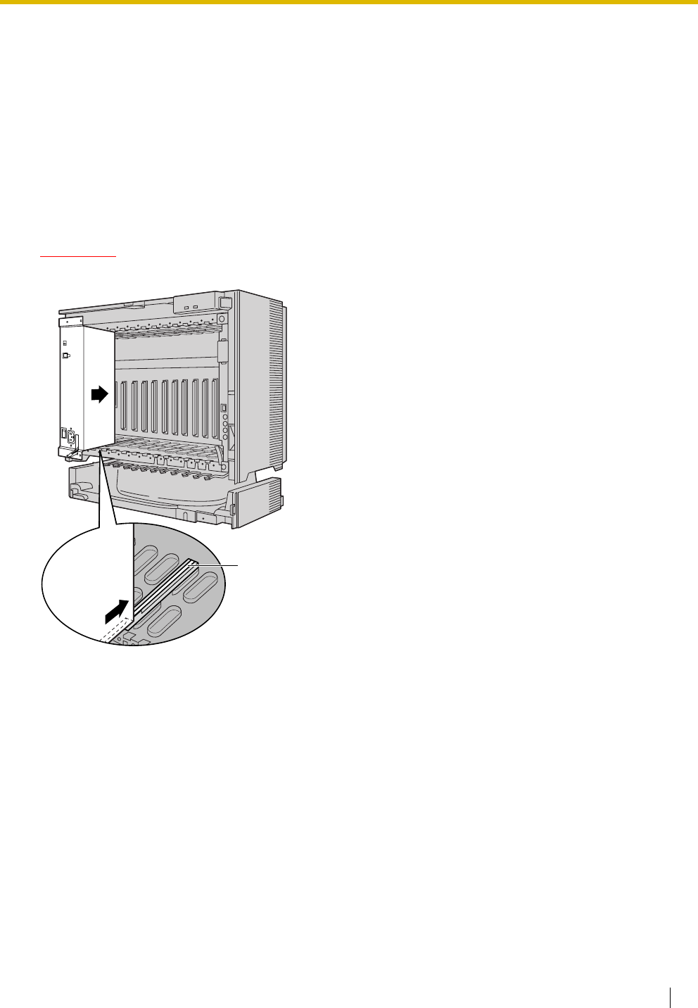
1. Insert the PSU along the guide rails.
CAUTION
For safety reasons, do not touch parts in the PSU.
Guide Rail
2.2 Installation of the Hybrid IP-PBX
46 Installation Manual
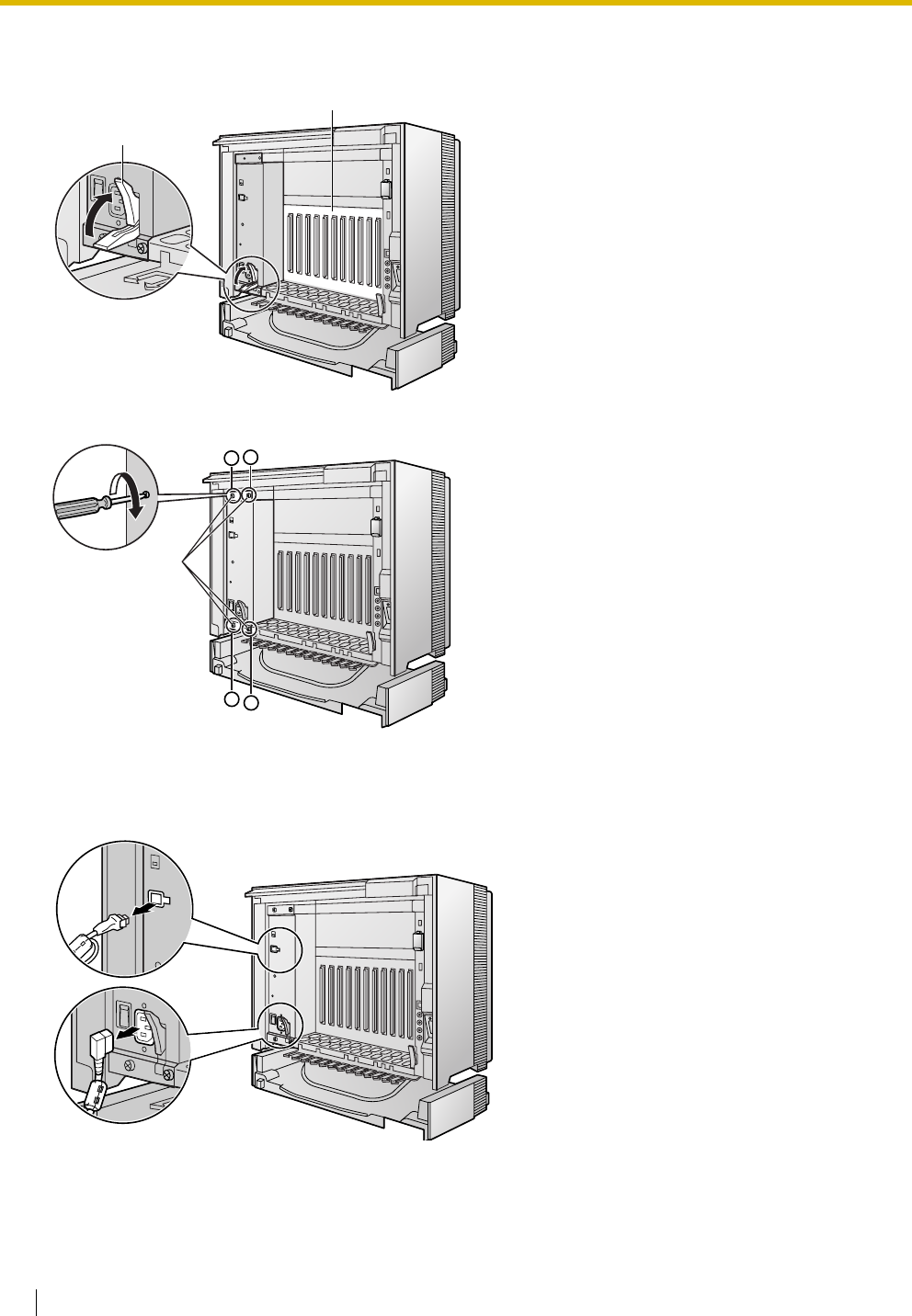
2. Push the release lever in the direction of the arrow, so that the PSU engages securely with the
connector on the back board.
3. Turn the 4 screws clockwise, in the order indicated by the numbers 1 to 4, to fix the PSU.
Replacing the Power Supply Unit
1. Unplug the AC power cord and Back-up Battery Cable.
Release Lever
Back Board
Screws
1
32
4
2.2 Installation of the Hybrid IP-PBX
Installation Manual 47
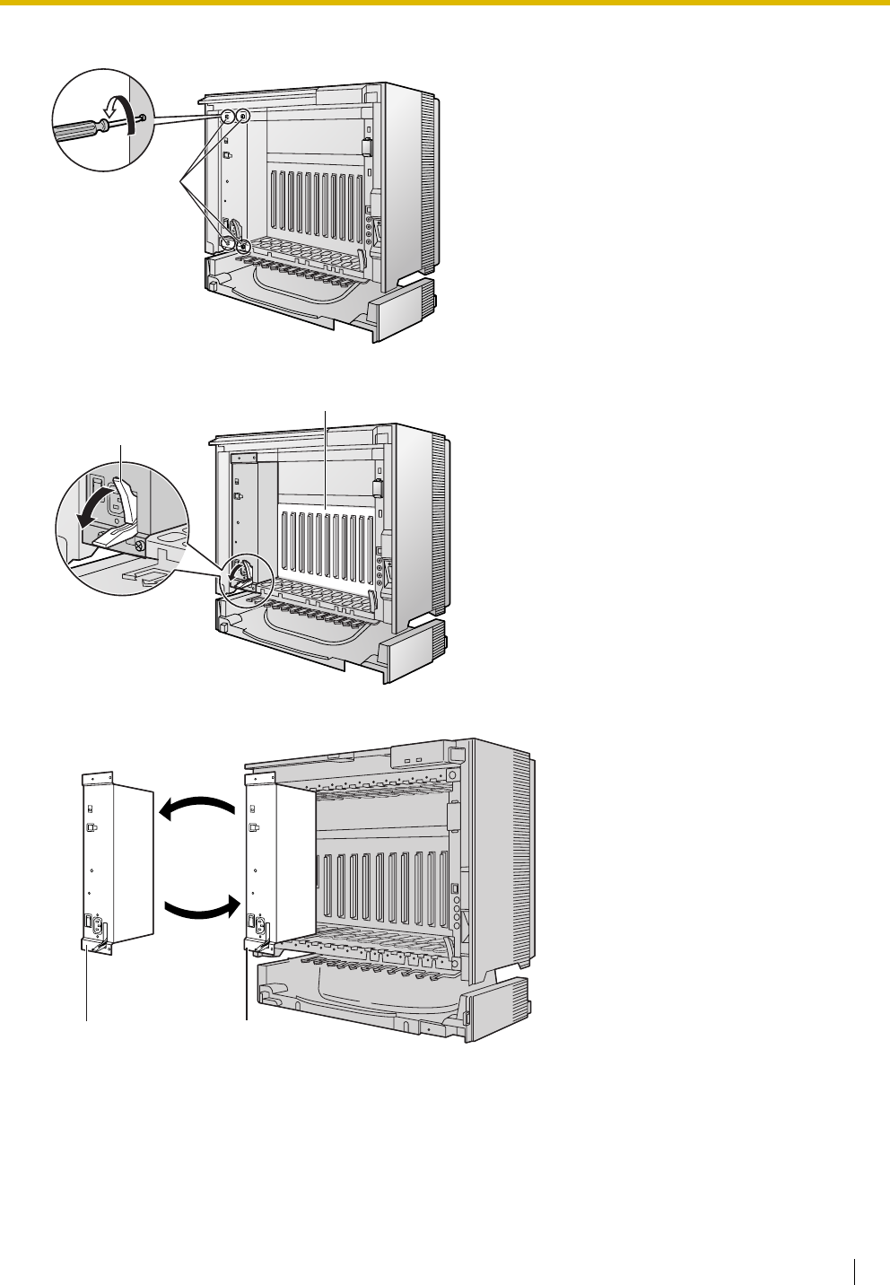
2. Turn the 4 screws anticlockwise to loosen them.
3. Pull the release lever in the direction of the arrow to disconnect the PSU from the back board.
4. Replace the PSU.
5. Follow the steps in "Installing the Power Supply Unit".
Screws
Release Lever
Back Board
Current PSU
New PSU
2.2 Installation of the Hybrid IP-PBX
48 Installation Manual
2.2.5 Frame Earth Connection
IMPORTANT
Connect the frame of the Hybrid IP-PBX to earth.
• Be sure to comply with applicable local regulations (e.g., laws, guidelines).
• Proper earthing (connection to earth) is very important to protect the Hybrid IP-PBX from the bad
effects of external noise or to reduce the risk to the user of electrocution in the case of a lightning strike.
• The earthing wire of the AC cable has an effect against external noise and lightning strikes, but it may
not be enough to protect the Hybrid IP-PBX. A permanent connection between earth and the earth
terminal of the Hybrid IP-PBX must be made.
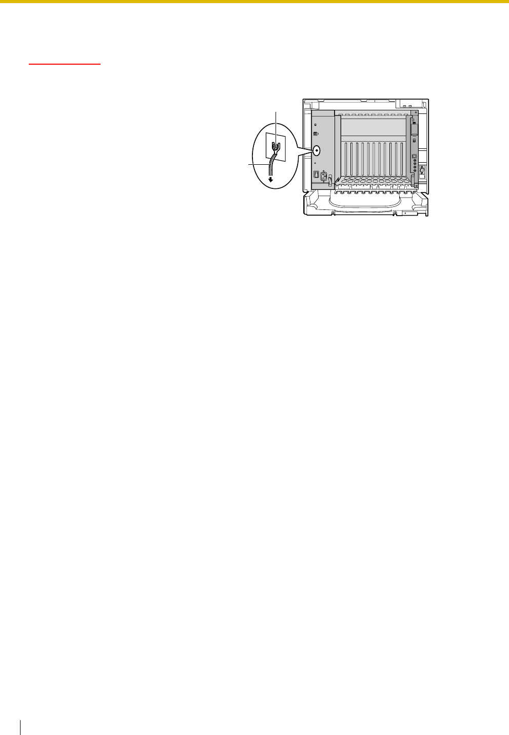
1. Loosen the screw.
2. Insert an earthing wire (user-
supplied)*.
3. Tighten the screw.
4. Connect the earthing wire to
earth.
* For earthing wire, green-and-yellow insulation is required, and the cross-sectional area of the conductor
must be more than 0.75 mm2 or 18 AWG.
Screw
To earth
Earthing
wire

2.2 Installation of the Hybrid IP-PBX
Installation Manual 49
2.2.6 Backup Battery Connection
The backup batteries and Back-up Battery Cable provide a backup power supply to allow full use of the
Hybrid IP-PBX in the event of a power failure. In case of power failure, the backup batteries automatically
maintain the power to the Hybrid IP-PBX without interruption.
User-supplied Items
• Backup Batteries: VRLA (Valve Regulated Lead Acid) 12 V DC × 3
• Back-up Battery Cable: KX-A228 (for PSU-S and PSU-M) or KX-A229 (for PSU-L)
CAUTION
• Make sure that the Back-up Battery Cable is securely fastened to both the backup batteries and
the Hybrid IP-PBX.
• Be sure to comply with applicable local regulations (e.g., laws, guidelines).
• Make sure that the polarities of the backup batteries and wiring are correct.
• Make sure that you do not short the backup batteries or cables.
• There is a danger of explosion if backup batteries are incorrectly replaced. Replace only with the
same or equivalent type recommended by the battery manufacturer. Dispose of used batteries
according to the manufacturer's instructions.
• Use the correct type of Back-up Battery Cable for the PSU.
Notes
• Turn on the battery switch on the PSU only after the installation of the Hybrid IP-PBX is finished
and AC power is available.
• The recommended maximum capacity is 28 Ah, to maintain effective battery charge.
• Make sure that the type and capacity of the 3 backup batteries are identical.
• The Back-up Battery Cable should not be exposed to direct sunlight. Keep the Back-up Battery
Cable and the backup batteries away from heating appliances and fire. Place the backup batteries
in a ventilated place.
• For details about the backup batteries, refer to the manual for the batteries.
Backup Power Supply Duration
The length of time that backup batteries can power the Hybrid IP-PBX varies depending on the total load
figure. For how to calculate the load figure from the connected items, refer to "Load Figure Calculation".
Examples
Battery Capacity Total Load Figure Backup Power Supply Duration*1
*1 The duration may vary depending on the conditions.
28 Ah
64 11 h
128 5.5 h
512 3 h
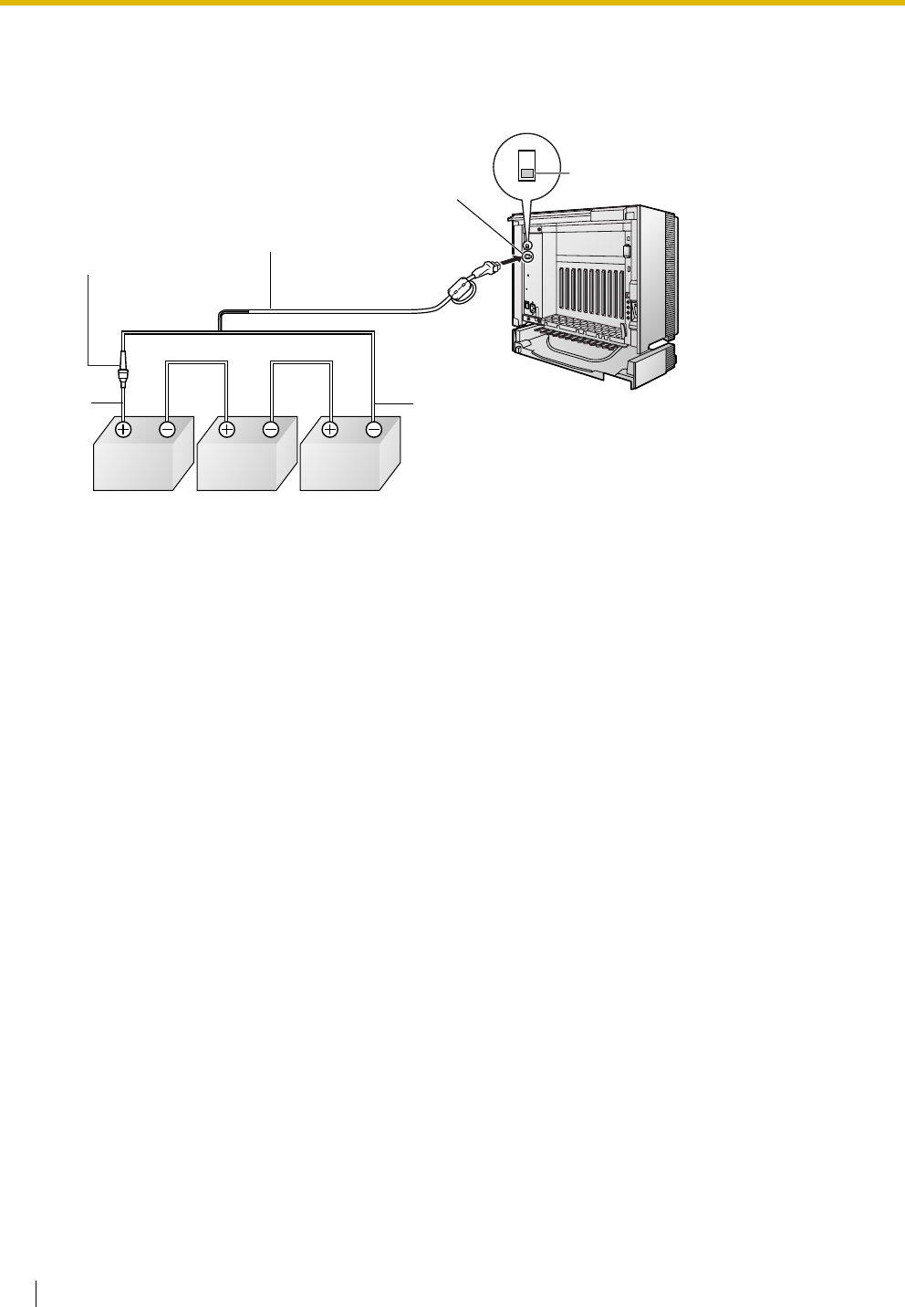
2.2 Installation of the Hybrid IP-PBX
50 Installation Manual
Connecting Backup Batteries
1. Turn off the battery switch on the PSU.
2. Connect the Back-up Battery Cable to a set of 3 identical batteries.
Back-up Battery Cable
Backup Batteries (VRLA 12 V DC x 3)
Red Black
Battery Connector
Battery Switch
ON
OFF
Fuse
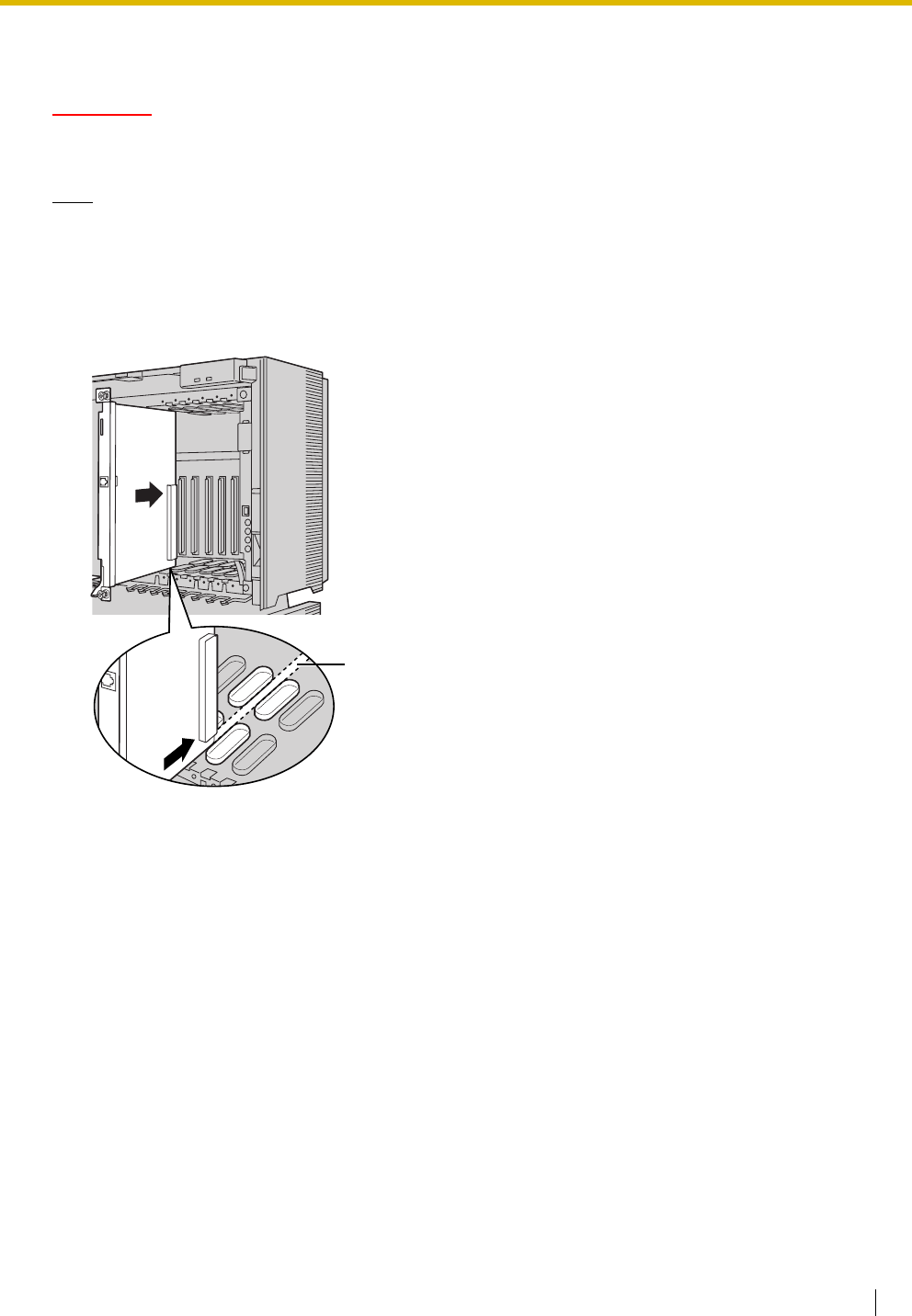
2.2 Installation of the Hybrid IP-PBX
Installation Manual 51
2.2.7 Installing/Removing the Optional Service Cards
CAUTION
To protect the back board from static electricity, do not touch parts on the back board in the main unit
and on the optional service cards. To discharge static electricity, touch ground or wear an earthing strap.
Note
The optional service cards can be installed or removed while the DC power is supplied. However, when
installing or removing the MPR card, the DC power supply must be turned off.
Installing Optional Service Cards
1. Insert the card along the guide rails.
Guide Rail
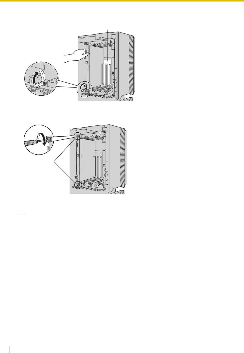
2.2 Installation of the Hybrid IP-PBX
52 Installation Manual
2. Holding the card as shown below, push the release lever in the direction of the arrow so that the card
engages securely with the connector on the back board.
3. Turn the 2 screws clockwise to fix the card in place.
Note
Make sure the screws are tightened to earth the card securely.
Release Lever
Back Board
Screws
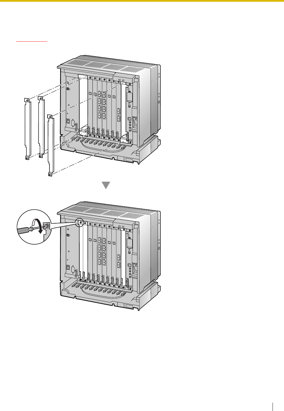
2.2 Installation of the Hybrid IP-PBX
Installation Manual 53
Covering the Blank Slots
Be sure to cover each slot in which no optional service card is installed by using a Blank Slot Cover.
CAUTION
Failure to install the Blank Slot Cover may cause electromagnetic interference.
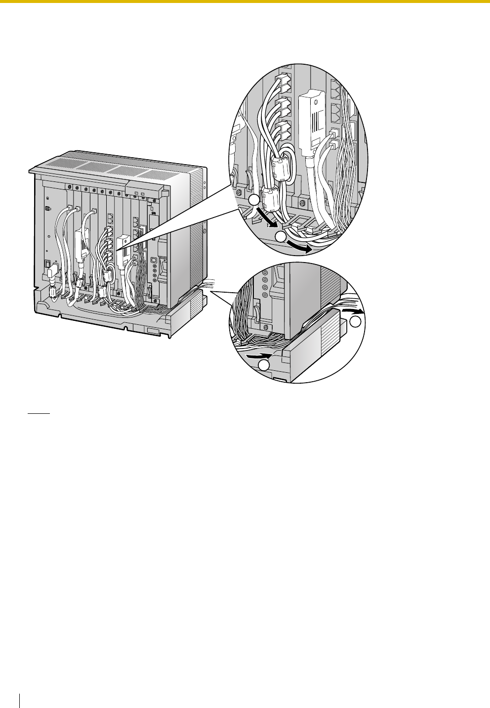
2.2 Installation of the Hybrid IP-PBX
54 Installation Manual
Handling of the Cables
When cables are connected to the Hybrid IP-PBX, run the cables to either the right or the left and then
towards the back of the shelf as shown below.
Note
For safety reasons, do not stretch, bend, or pinch the AC power cord.
3
4
1
2
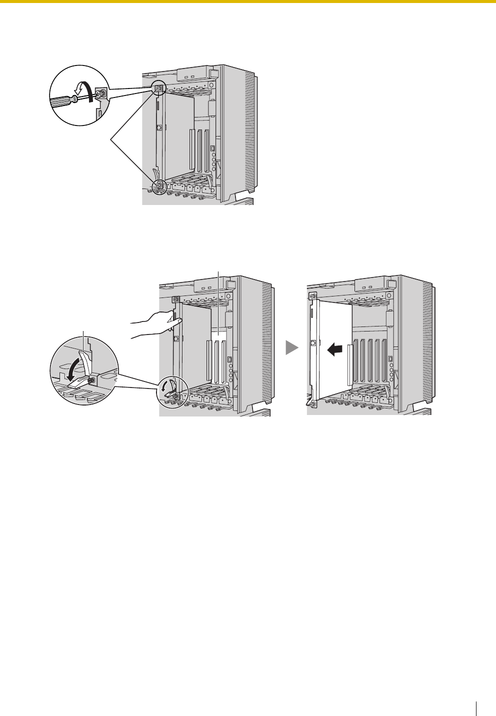
2.2 Installation of the Hybrid IP-PBX
Installation Manual 55
Removing the Optional Service Cards
1. Turn the 2 screws anticlockwise to loosen them.
2. Pull the release lever in the direction of the arrow to disconnect the card from the back board. Pull the
card from the shelf to remove it.
Screws
Release Lever
Back Board
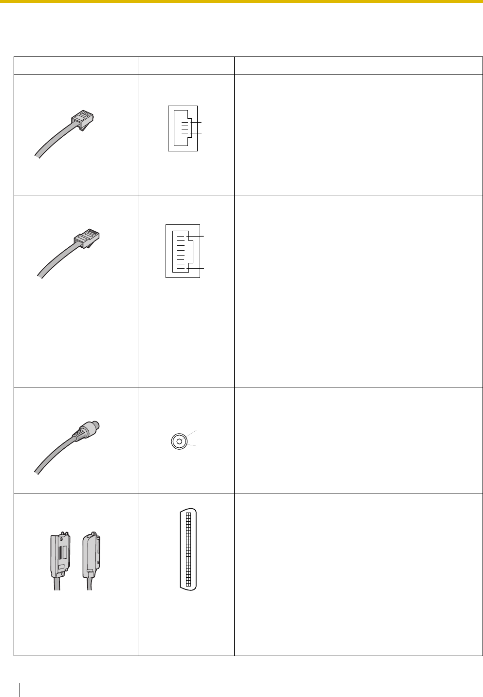
2.2 Installation of the Hybrid IP-PBX
56 Installation Manual
2.2.8 Types of Connectors
Connector Type Pin Number Used for
(Twisted pair cable)
• DHLC8 (KX-TDA0170)
• SLC8 (KX-TDA0173)
• SLC16 (KX-TDA0174)
• MSLC16 (KX-TDA0175)
• LCOT8 (KX-TDA0180)
• LCOT16 (KX-TDA0181)
• LCOT4 (KX-TDA0183)
(Twisted pair cable)
• CSIF4 (KX-TDA0143)
• CSIF8 (KX-TDA0144)
• T1 (KX-TDA0187)
• E1 (KX-TDA0188)
• BRI4 (KX-TDA0284)
• BRI8 (KX-TDA0288)
• PRI30 (KX-TDA0290CE/CJ)
• PRI23 (KX-TDA0290)
• CTI-LINK (KX-TDA0410)
• IP-EXT16 (KX-TDA0470)
• IP-GW4 (KX-TDA0480)
• IP-GW4E (KX-TDA0484)
• IP-GW16 (KX-TDA0490)
• E1 (KX-TDA0188)
• PRI30 (KX-TDA0290CE/CJ)
(Shielded twisted pair
cable)
• DHLC8 (KX-TDA0170)
• DLC8 (KX-TDA0171)
• DLC16 (KX-TDA0172)
• SLC8 (KX-TDA0173)
• SLC16 (KX-TDA0174)
• MSLC16 (KX-TDA0175)
• LCOT8 (KX-TDA0180)
• LCOT16 (KX-TDA0181)
• DID8 (KX-TDA0182)
• LCOT4 (KX-TDA0183)
• E&M8 (KX-TDA0184)
RJ11
1
4
RJ45
8
1
BNC
1
2
Amphenol
Type A Type B
50 25
26 1
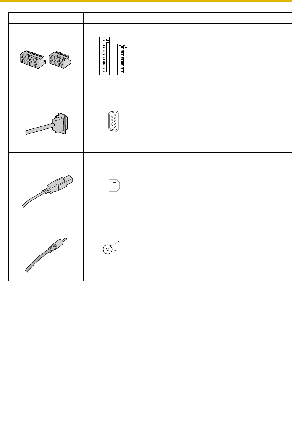
2.2 Installation of the Hybrid IP-PBX
Installation Manual 57
• DPH4 (KX-TDA0161)
• DPH2 (KX-TDA0162)
• EIO4 (KX-TDA0164)
• IP-GW4 (KX-TDA0480)
• Basic Shelf
•MPR
•MPR
Connector Type Pin Number Used for
10-pin
Terminal
Block
8-pin
Terminal
Block
8
1
10
1
RS-232C
9 5
6 1
USB
2
1
3
4
Mini Plug
2
4
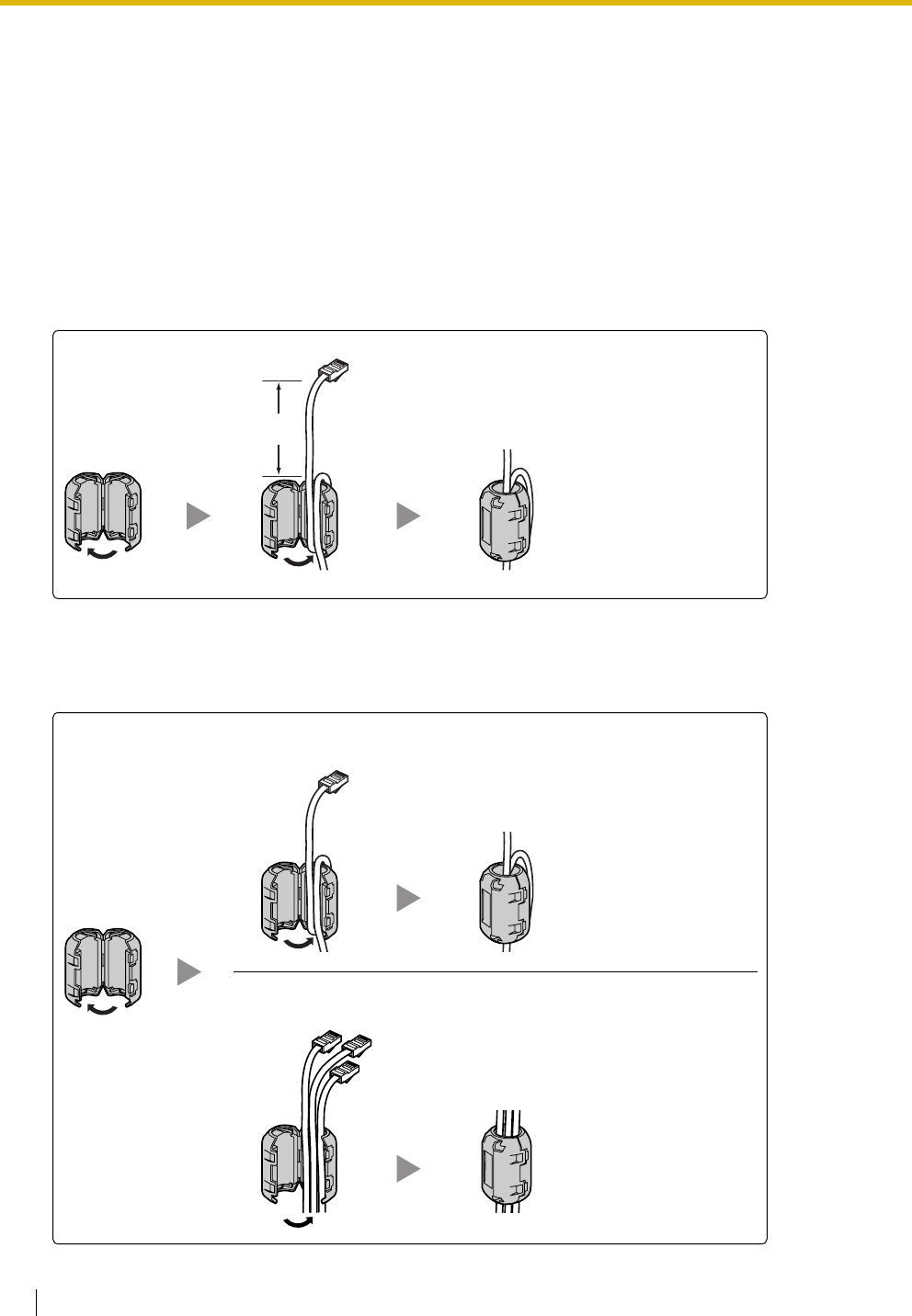
2.2 Installation of the Hybrid IP-PBX
58 Installation Manual
2.2.9 Attaching a Ferrite Core
A ferrite core must be attached when:
• connecting T1, E1, PRI, BRI, IP-GW16, and IP-EXT16 cards using an RJ45 connector (except in
Canada, where the ferrite core is not necessarily required), or
• connecting extension cards using an Amphenol connector.
The ferrite core is included with the card.
When connecting a T1/E1/PRI/IP-GW16/IP-EXT16 card
Wrap the cable once around the ferrite core, then close the case of the ferrite core. Attach the ferrite core 5
cm away from the connector.
When connecting a BRI card
Attach the ferrite core, then close the case of the ferrite core. Attach the ferrite core as close to the card's
connector as possible.
5 cm
When only 1 or 2 cables are used for connection, wrap the
cable(s) once around the ferrite core.
When 3 or 4 cables are used for connection, simply pass the
cables through the ferrite core.
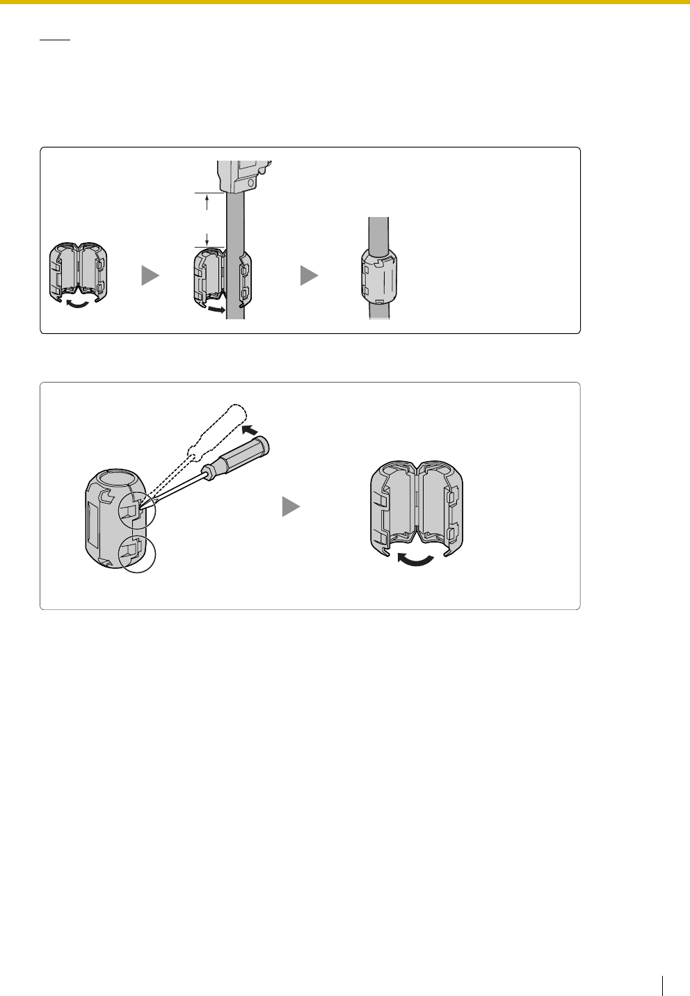
2.2 Installation of the Hybrid IP-PBX
Installation Manual 59
Note
For every 4 cables, use 1 ferrite core; a ferrite core holds a maximum of 4 cables.
When connecting an extension card
Pass the cable through the ferrite core, then close the case of the ferrite core. Attach the ferrite core 3 cm
away from the connector.
If you need to open the ferrite core, use a flathead screwdriver to unlatch the case of the ferrite core.
3 cm
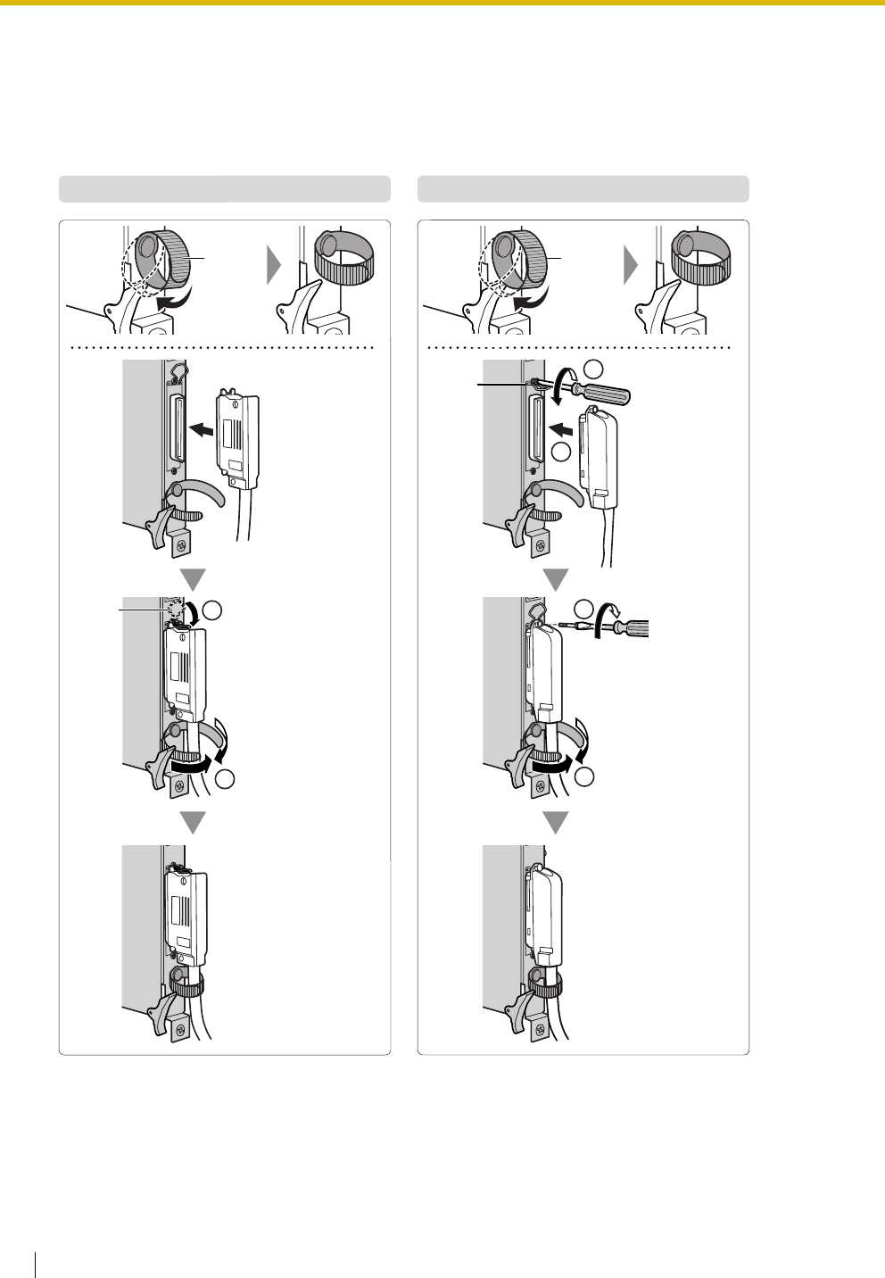
2.2 Installation of the Hybrid IP-PBX
60 Installation Manual
2.2.10 Fastening Amphenol Connector
An Amphenol 57JE-type connector is used on some of the optional service cards.
To connect an Amphenol connector, use the spring latch or screw to fix the upper part and use Velcro tape
to fix the lower part of the connector.
®
Type A (Spring Latch + Velcro Tape) Type B (Screw + Velcro Tape)
Velcro
Tape
Velcro
Tape
2
1
2
2
1
Spring
Latch
1
Spring
Latch
Remove the
screw on the
optional service
card.
Insert the screw (included
with the Amphenol or
optional service card).

2.2 Installation of the Hybrid IP-PBX
Installation Manual 61
Amphenol Connector Pin Assignment Chart
Below is an Amphenol connector pin assignment chart for all optional service cards that use the Amphenol
connector. For more details, refer to the appropriate section in "2.4 Information about the Trunk Cards" and
"2.5 Information about the Extension Cards".
Pin No. LCOT4 LCOT8 LCOT16 DID8 E&M8 DHLC8 DLC8 DLC16 MSLC16 SLC16 SLC8
1 RA RA RA RA TA RA D2A RA RA RA
26 TA TA TA TA RA TA D1A TA TA TA
2 RB RB RB RB T1A D2A D2A D2B RB RB
27 TB TB TB TB R1A D1A D1A D1B TB TB
3RCRCRCRC EA D2C RC RC
28 TC TC TC TC MA D1C TC TC
4 RD RD RD RD SGA RB D2D RD RD RB
29 TD TD TD TD SGB TB D1D TD TD TB
5RE RE RE TB D2B D2B D2E RE RE
30 TE TE TE RB D1B D1B D1E TE TE
6RF RF RF T1B D2F RF RF
31 TF TF TF R1B D1F TF TF
7RG RG RG EB RC D2G RG RG RC
32 TG TG TG MB TC D1G TG TG TC
8RH RH RH TC D2C D2C D2H RH RH
33 TH TH TH RC D1C D1C D1H TH TH
9 RI T1C D2I RI RI
34 TI R1C D1I TI TI
10 RJ EC RD D2J RJ RJ RD
35 TJ MC TD D1J TJ TJ TD
11 RK TD D2D D2D D2K RK RK
36 TK RD D1D D1D D1K TK TK
12 RL T1D D2L RL RL
37 TL R1D D1L TL TL
13 RM ED RE D2M RM RM RE
38 TM MD TE D1M TM TM TE
14 RN TE D2E D2E D2N RN RN
39 TN RE D1E D1E D1N TN TN
15 RO T1E D2O RO RO
40 TO R1E D1O TO TO
16 RP EE RF D2P RP RP RF
41 TP ME TF D1P TP TP TF
17 TF D2F D2F
42 RF D1F D1F
18 T1F
43 R1F
19 EF RG RG
44 MF TG TG
20 TG D2G D2G
45 RG D1G D1G
21 T1G
46 R1G
22 EG RH RH
47 MG TH TH
23 TH D2H D2H
48 RH D1H D1H
24 T1H
49 R1H
25 EH
50 MH
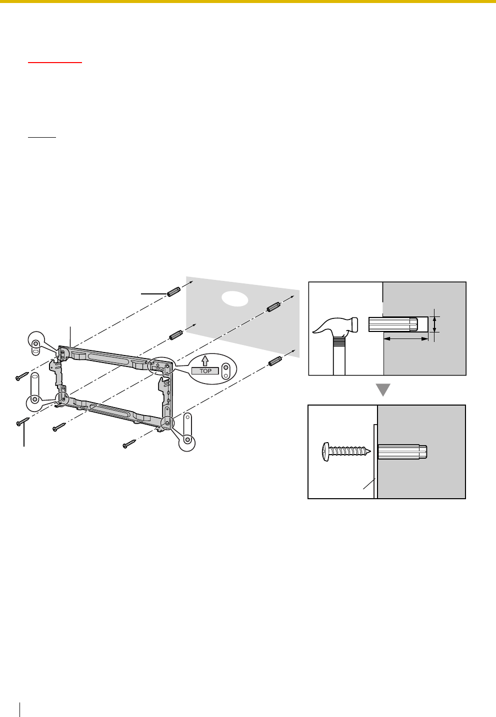
2.2 Installation of the Hybrid IP-PBX
62 Installation Manual
2.2.11 Wall Mounting (KX-TDA200)
CAUTION
• Make sure that the wall the shelf will be attached to is capable of supporting at least 4 times the
weight of the shelf.
• Drive mounting screws into the wall. Be careful to avoid touching any metal laths, wire laths or
metal plates in the wall.
Notes
• Do not block the openings of the shelf. Allow space of at least 20 cm above and 10 cm at the sides
of the shelf.
• Make sure that the surface behind the shelf is flat and free of obstacles, so that the openings on
the back of the shelf will not be blocked.
• Make sure that the surface behind the shelf is not made of wood.
• Be careful not to drop the shelf.
1. Install 4 anchor plugs in the wall, using the metal bracket as a template. Fix the metal bracket with 4
screws (A).
30 mm
8 mm
Anchor Plug
Metal Bracket
Wall
Screw (A)
Screw (A)
Metal Bracket
Hammer Anchor Plug
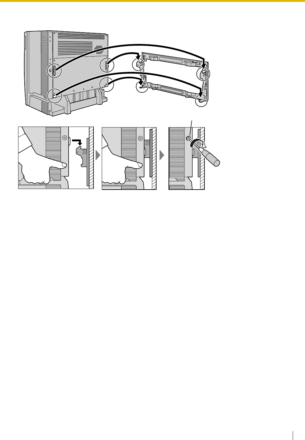
2.2 Installation of the Hybrid IP-PBX
Installation Manual 63
2. Hook the shelf onto the metal bracket, making sure that the shelf slides down and onto the hooked parts
of the metal bracket. Use 2 screws (B) to fix both sides of the shelf.
TOP
Screw (B)
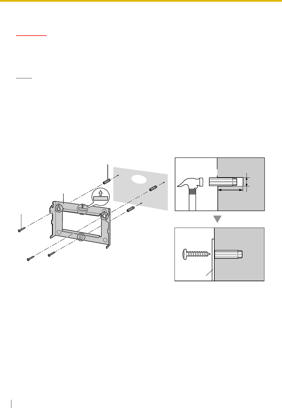
2.2 Installation of the Hybrid IP-PBX
64 Installation Manual
2.2.12 Wall Mounting (KX-TDA100)
CAUTION
• Make sure that the wall the shelf will be attached to is capable of supporting at least 4 times the
weight of the shelf.
• Drive mounting screws into the wall. Be careful to avoid touching any metal laths, wire laths or
metal plates in the wall.
Notes
• Do not block the openings of the shelf. Allow space of at least 20 cm above and 10 cm at the sides
of the shelf.
• Make sure that the surface behind the shelf is flat and free of obstacles, so that the openings on
the back of the shelf will not be blocked.
• Make sure that the surface behind the shelf is not made of wood.
• Be careful not to drop the shelf.
1. Install 3 anchor plugs in the wall, using the metal bracket as a template. Fix the metal bracket with 3
screws (A).
TOP
30 mm
8 mm
TOP
Metal Bracket
Screw (A)
Anchor Plug
Screw (A)
Metal Bracket
Hammer Anchor Plug
Wall
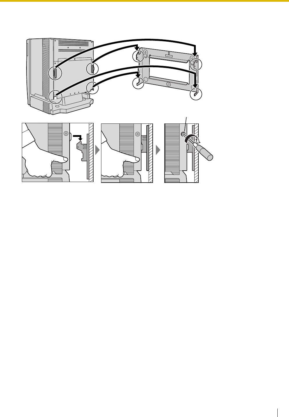
2.2 Installation of the Hybrid IP-PBX
Installation Manual 65
2. Hook the shelf onto the metal bracket, making sure that the shelf slides down and onto the hooked parts
of the metal bracket. Use 2 screws (B) to fix both sides of the shelf.
TOP
Screw (B)
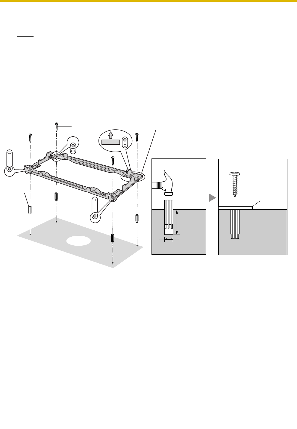
2.2 Installation of the Hybrid IP-PBX
66 Installation Manual
2.2.13 Floor Standing (KX-TDA200 Only)
Notes
• Do not block the openings of the shelf. Allow space of at least 20 cm above and 10 cm at the sides
of the shelf.
• Make sure that the surface behind the shelf is flat and free of obstacles, so that the openings on
the back of the shelf will not be blocked.
• Make sure that the surface behind the shelf is not made of wood.
• Be careful not to drop the shelf.
1. Install 4 anchor plugs in the floor, using the metal bracket as a template. Fix the metal bracket with 4
screws (A).
2. Remove the front cover of the shelf (refer to "2.2.3 Opening/Closing the Front Cover").
TOP
30 mm
8 mm
Floor
Screw (A) Metal Bracket
Anchor
Plug
Anchor
Plug
Hammer
Metal
Bracket
Screw (A)
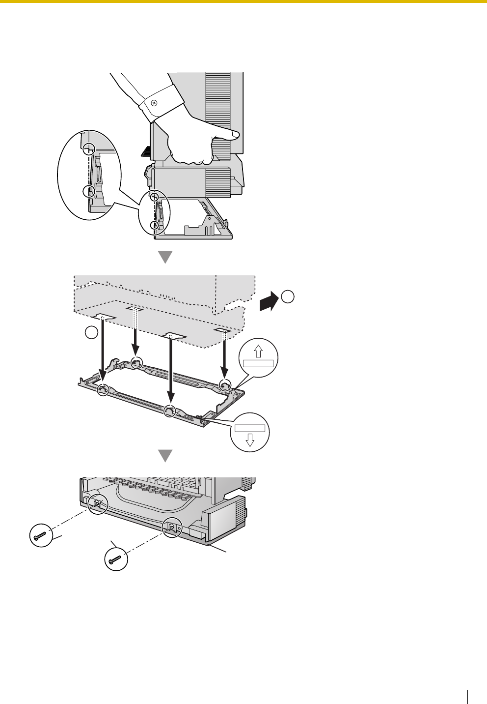
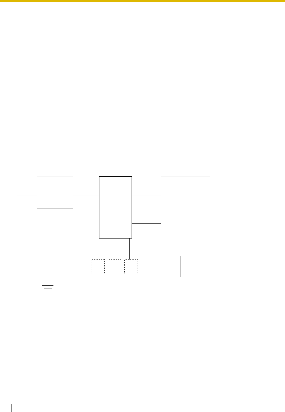
2.2 Installation of the Hybrid IP-PBX
68 Installation Manual
2.2.14 Surge Protector Installation
Overview
A massive electrical surge can be caused if lightning strikes a telephone cable 10 m above ground, or if a
telephone line comes into contact with a power line. A surge protector is a device that is connected to a trunk
to prevent potentially dangerous electrical surges from entering the building via the trunk and damaging the
Hybrid IP-PBX and connected equipment.
To protect the system from electrical surges, we strongly recommend connecting the system to a surge
protector that meets the following specifications:
– Surge arrestor type: 3-electrode arrestor
– DC spark-over voltage: 230 V
– Maximum peak current: at least 10 kA
Additionally, proper earthing is very important for the protection of the system (refer to "2.2.5 Frame Earth
Connection").
Many countries/areas have regulations requiring surge protection. Be sure to comply with all applicable
laws, regulations, and guidelines.
Installation
CS
Trunk Trunk Trunk
Extn.
Extn. Extn.
Extn.: Extension line
Surge
Protector
Terminal
Board Hybrid
IP-PBX
Frame
Earth
SLT
Earth
PT
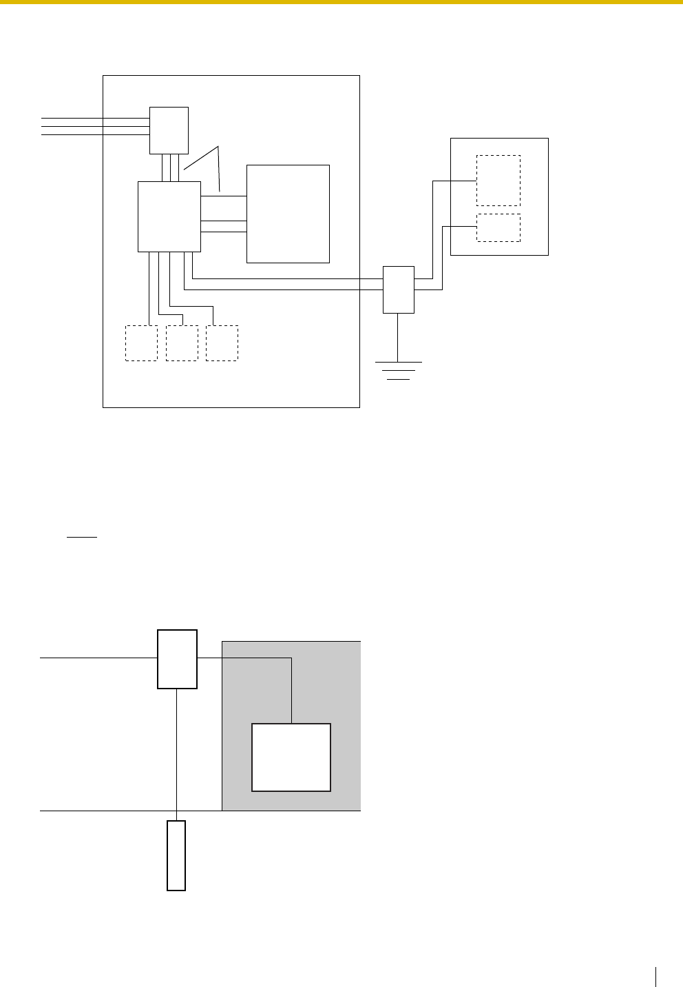
2.2 Installation of the Hybrid IP-PBX
Installation Manual 69
Outside Installation
If you install an extension outside of the building, the following precautions are recommended:
a. Install the extension wire underground.
b. Use a conduit to protect the wire.
Note
The surge protector for an extension and CS is different from that for a trunk.
Installation of an Earth Rod
CSSLT PT
(Main Building)
Trunk
Trunk
Extn.
Extn.
Extn.: Extension Line
Earth
(Another Building)
Extn. Extn.
Surge Protector
Terminal
Board Surge
Protector
SLT
PT
Hybrid
IP-PBX CS
Trunk
Hybrid
IP-PBX
Earthing
Wire
Earth Rod
(Underground)
Surge Protector

2.2 Installation of the Hybrid IP-PBX
70 Installation Manual
1. Connect the earth rod to the surge protector using an earthing wire with a cross-sectional area of at
least 1.3 mm2.
2. Bury the earth rod near the protector. The earthing wire should be as short as possible.
3. The earthing wire should run straight to the earth rod. Do not run the wire around other objects.
4. Bury the earth rod at least 50 cm underground.
Notes
• The above figures are recommendations only.
• The length of earth rod and the required depth depend on the composition of the soil.
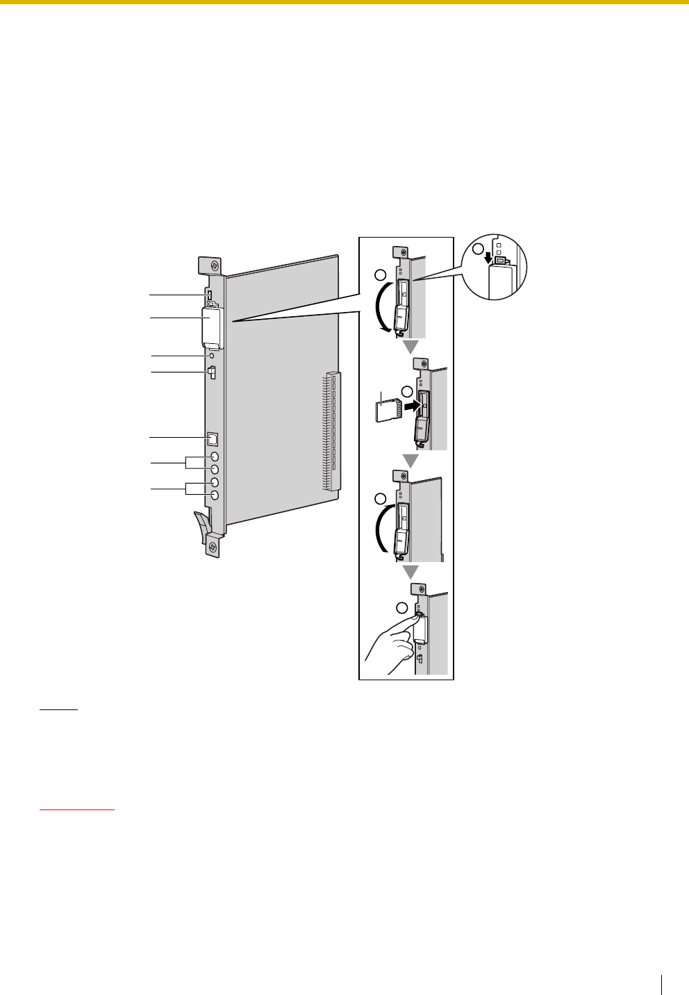
2.3 Information about the Main Processing Card
Installation Manual 71
2.3 Information about the Main Processing Card
2.3.1 MPR Card
Function
Contains the main processor for all processes, basic shelf main protocol, time switch (TSW) control,
detection of system clock alarm, basic shelf power down alarm, and watchdog timer overflow. An MEC card
and an RMT card can be mounted on the MPR card (refer to "2.3.2 MEC Card (KX-TDA0105)" and "2.3.3
RMT Card (KX-TDA0196)").
Notes
• For details about connecting peripherals, refer to "2.11.1 Connection of Peripherals".
• For details about System Initialise Switch, refer to "2.13.1 Starting the Hybrid IP-PBX".
• For details about Reset Button, refer to "4.1.4 Using the Reset Button".
CAUTION
• Use only the SD Memory Card included with the Hybrid IP-PBX, or a Panasonic optional upgrade
SD Memory Card.
• The SD Memory Card contains software for all the processes of the Hybrid IP-PBX and all the
customer data. The SD Memory Card must be inserted before start up.
• Do not remove the SD Memory Card while power is supplied to the Hybrid IP-PBX. Doing so may
cause the Hybrid IP-PBX to fail to start when you try to restart the system.
LEDs
Reset Button
SD Memory Card
Slot Cover
System Initialise
Switch
USB
BGM/MOH
Pager
SD
CARD
2
SD
CARD
4
5
SD
CARD
SD
Memory
Card
3
1

2.3 Information about the Main Processing Card
72 Installation Manual
• A LITHIUM BATTERY IS USED IN THE MPR CARD. THERE IS A RISK OF EXPLOSION IF THE
BATTERY IS REPLACED WITH THE INCORRECT TYPE. DISPOSE OF USED BATTERIES
ACCORDING TO THE MANUFACTURER'S INSTRUCTIONS.
LED Indications
Indication Colour Description
BATT ALARM Red Battery alarm indication
• OFF: Normal
ON: Alarm
SD ACCESS Green SD memory card status
• ON: Accessing
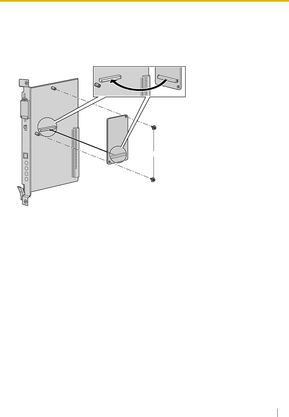
2.3 Information about the Main Processing Card
Installation Manual 73
2.3.2 MEC Card (KX-TDA0105)
Function
Memory expansion card to increase system data storage space, enable Broadcasting and Call Billing for
Guest Room features, and double the number of DPTs, using Digital XDP connection. To be mounted on
the MPR card.
Accessories and User-supplied Items
Accessories (included): Screws × 2
User-supplied (not included): none
MEC Card
Screw
inside
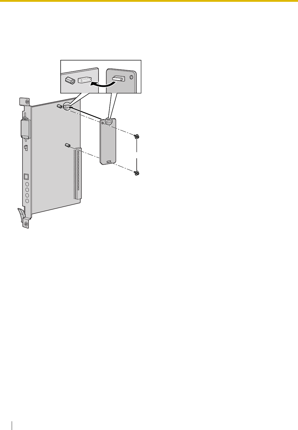
2.3 Information about the Main Processing Card
74 Installation Manual
2.3.3 RMT Card (KX-TDA0196)
Function
Analogue modem card for remote communication with the Hybrid IP-PBX. ITU-T V.90 support. To be
mounted on the MPR card.
Accessories and User-supplied Items
Accessories (included): Screws × 2
User-supplied (not included): none
RMT Card
Screw
inside
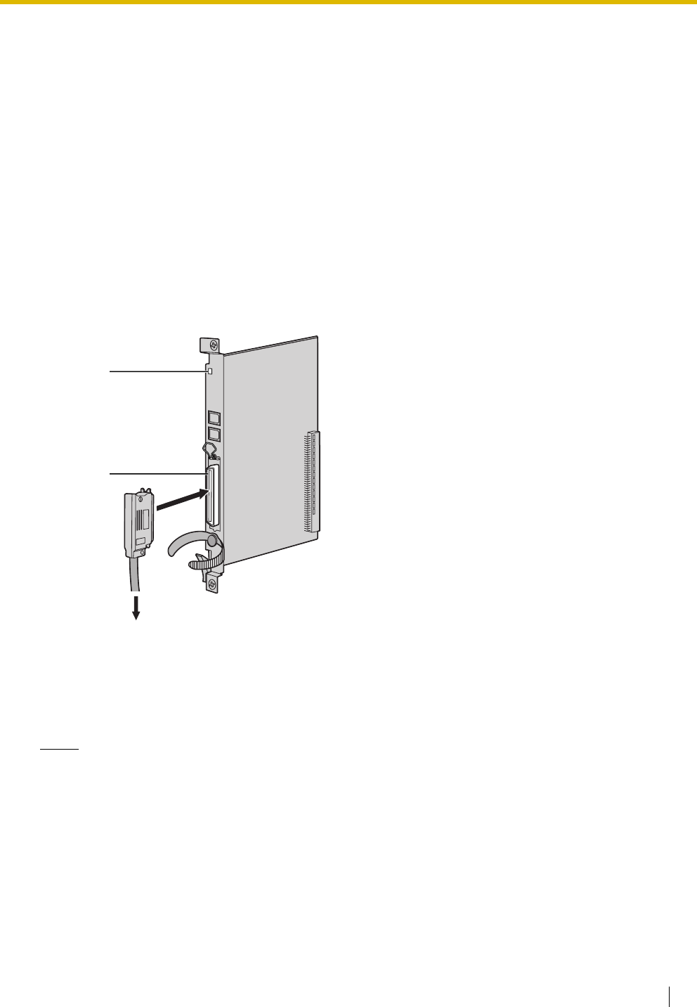
2.4 Information about the Trunk Cards
Installation Manual 75
2.4 Information about the Trunk Cards
2.4.1 LCOT4 Card (KX-TDA0183), LCOT8 Card (KX-TDA0180),
and LCOT16 Card (KX-TDA0181)
Function
Accessories and User-supplied Items
Accessories (included): Screws × 2
User-supplied (not included): Amphenol connector
Notes
• To connect the Amphenol connector, refer to "2.2.10 Fastening Amphenol Connector".
• For details about power failure transfer, refer to "2.12.1 Power Failure Connections".
• To confirm the trunk connection, refer to "Confirming the Trunk Connection" in "2.13.1 Starting the
Hybrid IP-PBX".
LCOT4: 4-port analogue trunk card with 2 power failure transfer (PFT) ports.
LCOT8: 8-port analogue trunk card with 2 power failure transfer (PFT) ports. One CID8 or CID/PAY8
card can be mounted on the LCOT8 card (refer to "2.4.3 CID/PAY8 Card (KX-TDA0189)" and
"2.4.4 CID8 Card (KX-TDA0193)").
LCOT16: 16-port analogue trunk card with 4 power failure transfer (PFT) ports. A maximum of 2 CID8
and CID/PAY8 cards can be mounted on the LCOT16 card (refer to "2.4.3 CID/PAY8 Card
(KX-TDA0189)" and "2.4.4 CID8 Card (KX-TDA0193)").
Amphenol
To trunk
LED
2.4 Information about the Trunk Cards
76 Installation Manual
Pin Assignments
Amphenol Connector
Notes
• Pin assignments for the pins 5 to 8 and 30 to 33 are for the LCOT8 and LCOT16 card only.
• Pin assignments for the pins 9 to 16 and 34 to 41 are for the LCOT16 card only.
LED Indications
No. Signal Name Function No. Signal Name Function
1 RA Ring port 1 26 TA Tip port 1
2 RB Ring port 2 27 TB Tip port 2
3 RC Ring port 3 28 TC Tip port 3
4 RD Ring port 4 29 TD Tip port 4
5 RE Ring port 5 30 TE Tip port 5
6 RF Ring port 6 31 TF Tip port 6
7 RG Ring port 7 32 TG Tip port 7
8 RH Ring port 8 33 TH Tip port 8
9 RI Ring port 9 34 TI Tip port 9
10 RJ Ring port 10 35 TJ Tip port 10
11 RK Ring port 11 36 TK Tip port 11
12 RL Ring port 12 37 TL Tip port 12
13 RM Ring port 13 38 TM Tip port 13
14 RN Ring port 14 39 TN Tip port 14
15 RO Ring port 15 40 TO Tip port 15
16 RP Ring port 16 41 TP Tip port 16
17-25 Reserved – 42-50 Reserved –
Indication Colour Description
CARD STATUS Green/Red Card status indication
• OFF: Power Off
• Green ON: Normal (all ports are idle)
• Green Flashing (60 times per minute): Normal (a port is in use)
• Red ON: Fault (includes reset)
• Red Flashing (60 times per minute): Out of Service
50 25
26 1
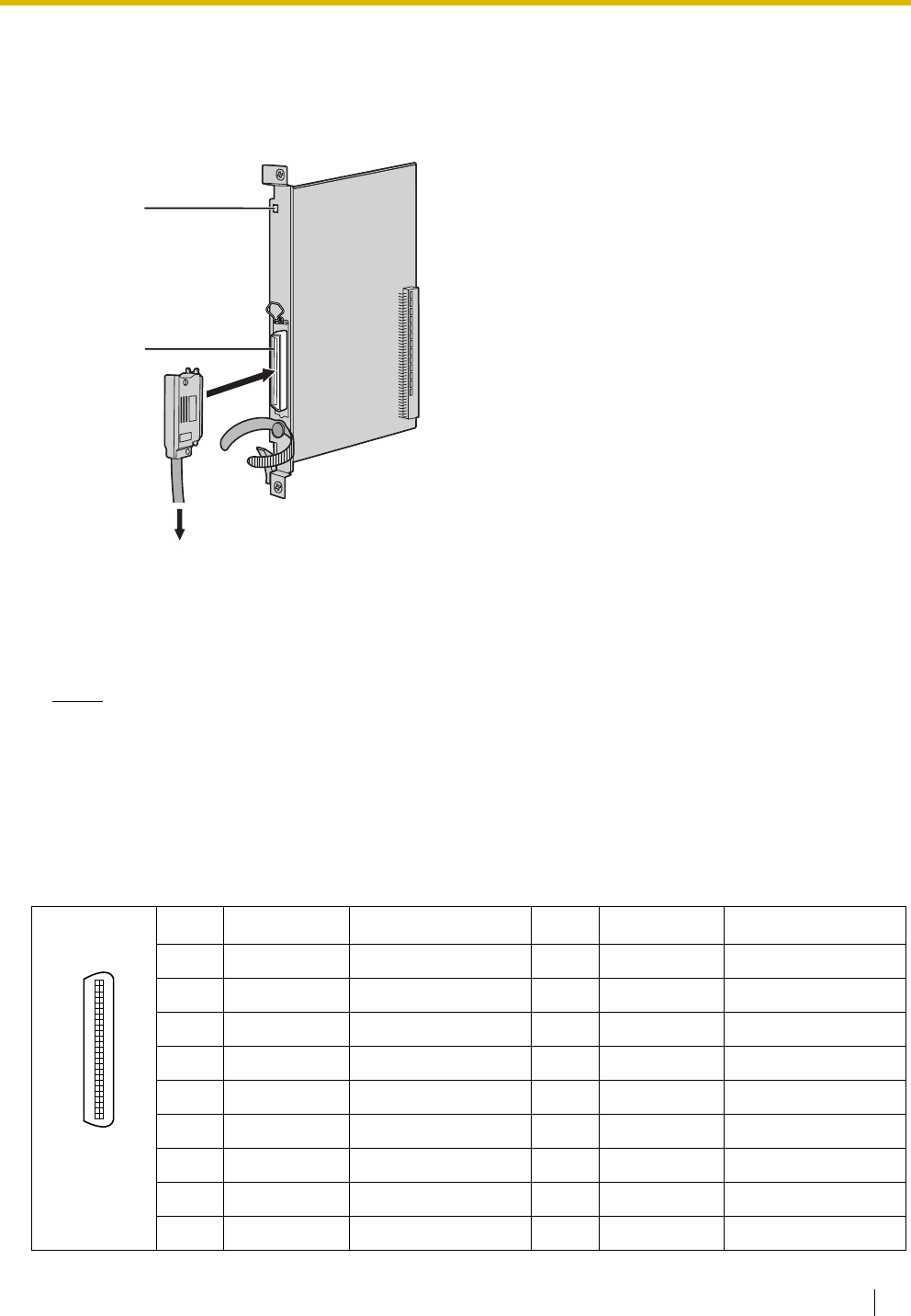
2.4 Information about the Trunk Cards
Installation Manual 77
2.4.2 DID8 Card (KX-TDA0182)
Function
8-port DID trunk card.
Accessories and User-supplied Items
Accessories (included): Screws × 2
User-supplied (not included): Amphenol connector
Notes
• To connect the Amphenol connector, refer to "2.2.10 Fastening Amphenol Connector".
• To confirm the trunk connection, refer to "Confirming the Trunk Connection" in "2.13.1 Starting the
Hybrid IP-PBX".
Pin Assignments
Amphenol Connector
No. Signal Name Function No. Signal Name Function
1 RA Ring port 1 26 TA Tip port 1
2 RB Ring port 2 27 TB Tip port 2
3 RC Ring port 3 28 TC Tip port 3
4 RD Ring port 4 29 TD Tip port 4
5 RE Ring port 5 30 TE Tip port 5
6 RF Ring port 6 31 TF Tip port 6
7 RG Ring port 7 32 TG Tip port 7
8 RH Ring port 8 33 TH Tip port 8
9-25 Reserved – 34-50 Reserved –
To DID line
LED
Amphenol
50 25
26 1

2.4 Information about the Trunk Cards
78 Installation Manual
LED Indications
Indication Colour Description
CARD STATUS Green/Red Card status indication
• OFF: Power Off
• Green ON: Normal (all ports are idle)
• Green Flashing (60 times per minute): Normal (a port is in use)
• Red ON: Fault (includes reset)
• Red Flashing (60 times per minute): Out of Service
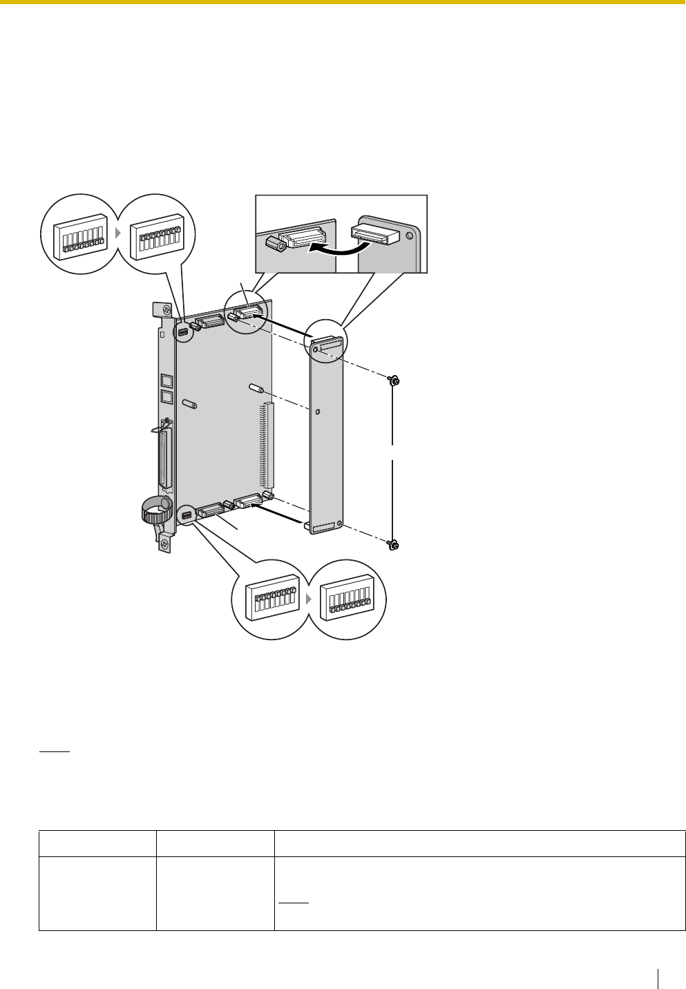
2.4 Information about the Trunk Cards
Installation Manual 79
2.4.3 CID/PAY8 Card (KX-TDA0189)
Function
8-port Caller ID signal type FSK/FSK (with Call Waiting Caller ID [Visual Caller ID])/DTMF, and 8-port Pay
Tone Service (12 kHz/16 kHz). To be mounted on the LCOT8/LCOT16 cards.
Accessories and User-supplied Items
Accessories (included): Screws × 2
User-supplied (not included): none
Note
Only 1 CID/PAY8 card can be mounted on the LCOT8 card.
Switch Settings (on LCOT8/LCOT16 cards)
Switch Type Usage and Status Definition
Port Setting DIP Set all DIP switches at "OFF" positions.
Note
SW2 is for the LCOT16 card only.
CID/PAY8 Card
inside
Screw
Set all DIP switches for
ports 01-08 at "OFF"
positions.
Set all DIP switches for ports
09-16 at "OFF" positions
(LCOT16 card only).
OFF
ON
OFF
ON
ON
OFF
ON
OFF
SW2
SW2
Ports 09-16
Ports 01-08
SW1
SW1
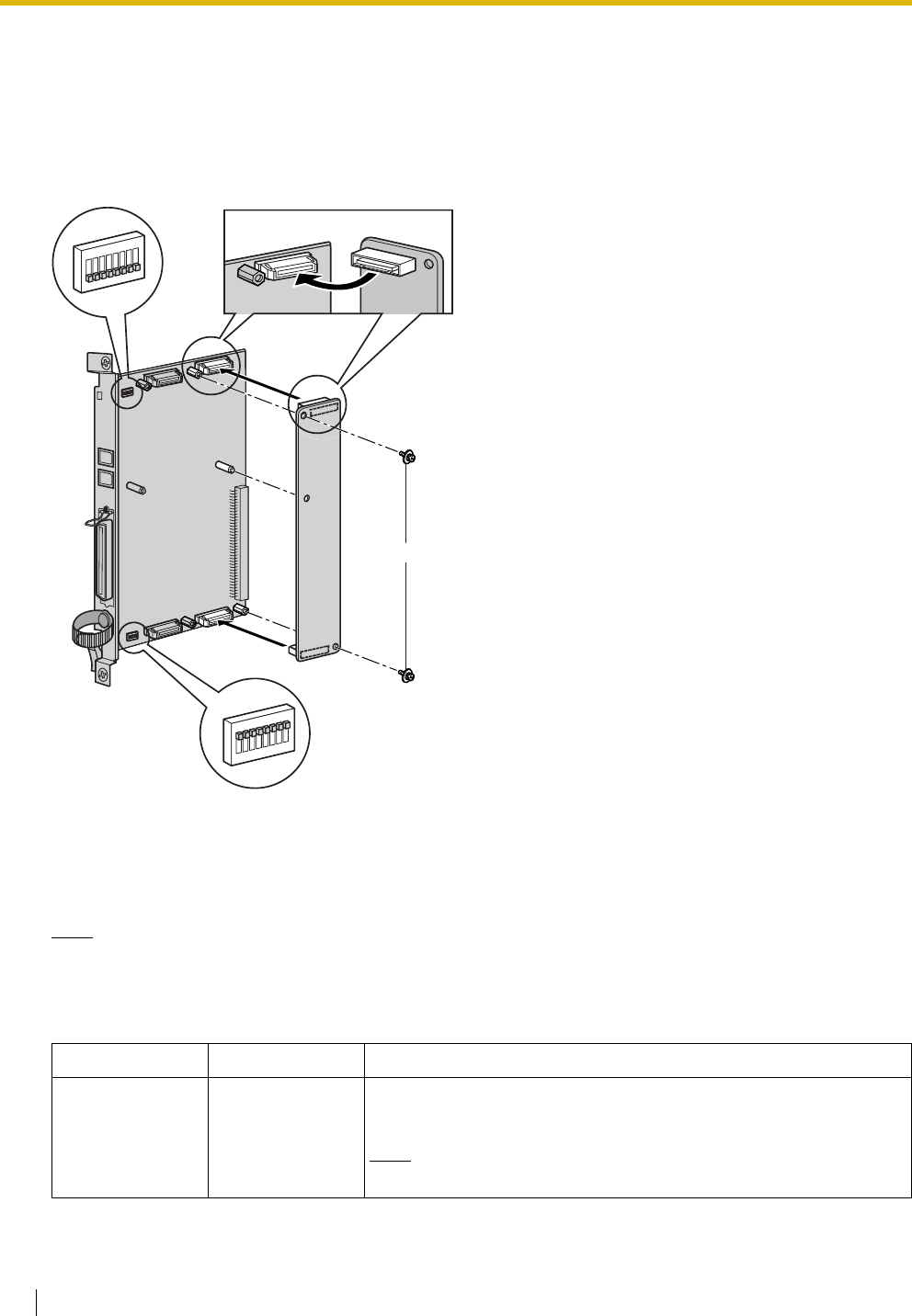
2.4 Information about the Trunk Cards
80 Installation Manual
2.4.4 CID8 Card (KX-TDA0193)
Function
8-port Caller ID signal type FSK/FSK (with Call Waiting Caller ID [Visual Caller ID])/DTMF. To be mounted
on the LCOT8/LCOT16 cards.
Accessories and User-supplied Items
Accessories (included): Screws × 2
User-supplied (not included): none
Note
Only 1 CID8 card can be mounted on the LCOT8 card.
Switch Settings (on LCOT8/LCOT16 cards)
Switch Type Usage and Status Definition
Port Setting DIP Keep all DIP switches at default "ON" positions. Do not change the
positions of these switches.
Note
SW2 is for the LCOT16 card only.
CID8 Card
inside
Screw
OFF
ON
ON
OFF
SW2
LCOT16 card only
SW1

2.4 Information about the Trunk Cards
Installation Manual 81
2.4.5 E&M8 Card (KX-TDA0184)
Function
8-port E & M (TIE) trunk card. Type 5 support.
Accessories and User-supplied Items
Accessories (included): Screws × 2
User-supplied (not included): Amphenol connector
Notes
• Connect this optional service card to the trunk through terminal board from the E & M (TIE) line;
do not connect to the trunk directly.
• To connect the Amphenol connector, refer to "2.2.10 Fastening Amphenol Connector".
• To confirm the trunk connection, refer to "Confirming the Trunk Connection" in "2.13.1 Starting the
Hybrid IP-PBX".
To terminal board from the E & M (TIE) line
LED
Amphenol

2.4 Information about the Trunk Cards
82 Installation Manual
Pin Assignments
Amphenol Connector
No. Signal Name Function No. Signal Name Function
1 TA Tip port 1 26 RA Ring port 1
2 T1A Tip 1 port 1 27 R1A Ring 1 port 1
3 EA E line port 1 28 MA M line port 1
4 SGA SG line port 1 29 SGB SG line port 2
5 TB Tip port 2 30 RB Ring port 2
6 T1B Tip 1 port 2 31 R1B Ring 1 port 2
7 EB E line port 2 32 MB M line port 2
8 TC Tip port 3 33 RC Ring port 3
9 T1C Tip 1 port 3 34 R1C Ring 1 port 3
10 EC E line port 3 35 MC M line port 3
11 TD Tip port 4 36 RD Ring port 4
12 T1D Tip 1 port 4 37 R1D Ring 1 port 4
13 ED E line port 4 38 MD M line port 4
14 TE Tip port 5 39 RE Ring port 5
15 T1E Tip 1 port 5 40 R1E Ring 1 port 5
16 EE E line port 5 41 ME M line port 5
17 TF Tip port 6 42 RF Ring port 6
18 T1F Tip 1 port 6 43 R1F Ring 1 port 6
19 EF E line port 6 44 MF M line port 6
20 TG Tip port 7 45 RG Ring port 7
21 T1G Tip 1 port 7 46 R1G Ring 1 port 7
22 EG E line port 7 47 MG M line port 7
23 TH Tip port 8 48 RH Ring port 8
24 T1H Tip 1 port 8 49 R1H Ring 1 port 8
25 EH E line port 8 50 MH M line port 8
50 25
26 1

2.4 Information about the Trunk Cards
Installation Manual 83
LED Indications
Indication Colour Description
CARD STATUS Green/Red Card status indication
• OFF: Power Off
• Green ON: Normal (all ports are idle)
• Green Flashing (60 times per minute): Normal (a port is in use)
• Red ON: Fault (includes reset)
• Red Flashing (60 times per minute): Out of Service
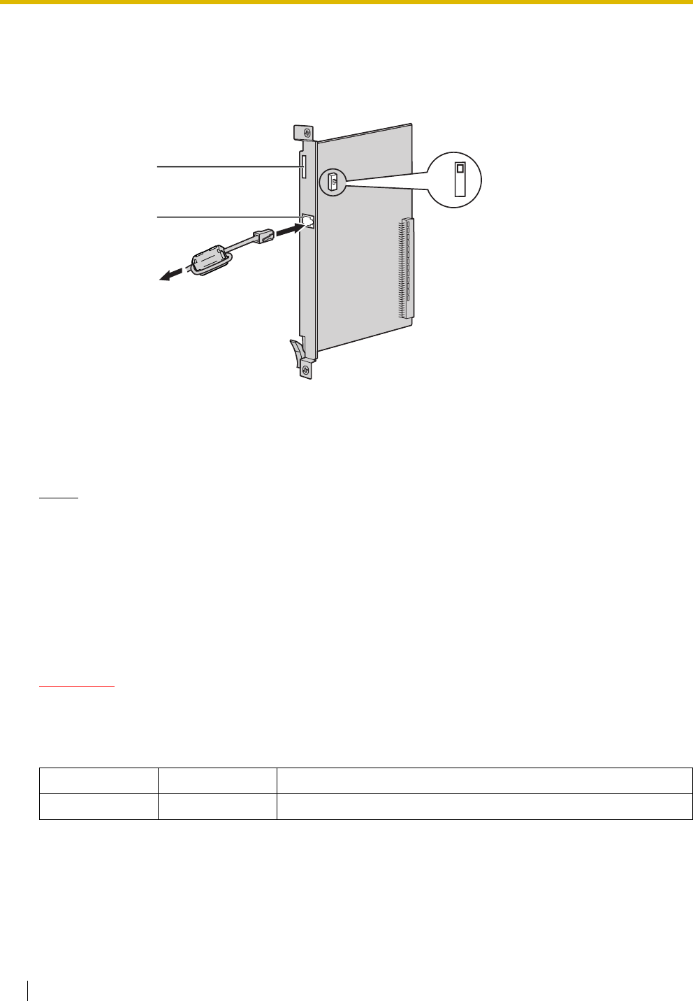
2.4 Information about the Trunk Cards
84 Installation Manual
2.4.6 T1 Card (KX-TDA0187)
Function
1-port T1 trunk card. EIA/TIA standard compliant.
Accessories and User-supplied Items
Accessories (included): Ferrite core × 1
User-supplied (not included): RJ45 connector
Notes
• When connecting this optional service card to the trunk, connect through NT1; do not connect to
the trunk directly.
• When connecting the RJ45 connector, attach the included ferrite core (except in Canada, where
the ferrite core is not necessarily required). Refer to "2.2.9 Attaching a Ferrite Core".
• This optional service card can be used for either trunk or extension connection, by setting the A/B
switch or using the connector with appropriate pin assignments.
• To confirm the trunk connection, refer to "Confirming the Trunk Connection" in "2.13.1 Starting the
Hybrid IP-PBX".
CAUTION
T1 ports are SELV ports and should only be connected to SELV services.
Switch Settings
Switch Type Usage and Status Definition
A/B Slide Select A (default) for trunk or B for extension use.
LEDs
RJ45
To NT1
/
Extension
AB
2.4 Information about the Trunk Cards
Installation Manual 85
Pin Assignments
RJ45 Connector for Trunk Use
RJ45 Connector for Extension Use
LED Indications
No. Signal Name Level [V] Function
1 RX+ (+) Receive data (+)
2 RX- (-) Receive data (-)
3 Reserved – –
4 TX- (-) Transmit data (-)
5 TX+ (+) Transmit data (+)
6-8 Reserved – –
No. Signal Name Level [V] Function
1 TX- (-) Transmit data (-)
2 TX+ (+) Transmit data (+)
3 Reserved – –
4 RX+ (+) Receive data (+)
5 RX- (-) Receive data (-)
6-8 Reserved – –
Indication Colour Description
CARD STATUS Green/Red Card status indication
• OFF: Power Off
• Green ON: Normal (all ports are idle)
• Green Flashing (60 times per minute): Normal (a port is in use)
• Red ON: Fault (includes reset)
• Red Flashing (60 times per minute): Out of Service
SYNC-ERR Red Non-synchronisation status indication
• OFF: Normal
• ON: Out of synchronisation
RAI Red RAI signal status indication
• OFF: Normal
•ON: Alarm (Clock Slave)
• Flashing (60 times per minute): Alarm (Clock Master)
AIS Red AIS status indication
• OFF: Normal
•ON: Alarm
8
1
8
1
2.4 Information about the Trunk Cards
86 Installation Manual
Maximum Cabling Distance of Extension Connection
The maximum length of the extension cable that connects the T1 cards is shown below:
SYNC Green Synchronisation status indication
• OFF: Not synchronised
• ON: Synchronised
• Flashing (60 times per minute): Synchronised (Clock Master)
Indication Colour Description
Diameter Maximum Distance
0.5 mm: 200 m
2.4 Information about the Trunk Cards
Installation Manual 87
2.4.7 E1 Card (KX-TDA0188)
Function
1-port E1 trunk card. ITU-T standard compliant.
Accessories and User-supplied Items
Accessories (included): Ferrite core × 1
User-supplied (not included): RJ45 or BNC connector
Notes
• In some countries/areas, this optional service card must not be connected to the Public Switched
Telephone Network.
• When connecting this optional service card to the trunk, connect through NT1; do not connect to
the trunk directly.
• Use only 1 type of connector (RJ45 or BNC) for connection; RJ45 and BNC cannot be used
simultaneously.
• When connecting the RJ45 connector, attach the included ferrite core. Refer to "2.2.9 Attaching a
Ferrite Core".
• This optional service card can be used for either trunk or extension connection, by setting the A/B
switch or using the connector with appropriate pin assignments.
• To confirm the trunk connection, refer to "Confirming the Trunk Connection" in "2.13.1 Starting the
Hybrid IP-PBX".
CAUTION
E1 ports are SELV ports and should only be connected to SELV services.
LEDs
To NT1/Extension
To NT1/Extension
BNC (TX)
BNC (RX)
BNC (TX) outer conductor
For Frame
Ground Open
For Frame
Ground Short
J308
123123
J308
J309
123
J309
123
BNC (RX) outer conductor
RJ45
OR
OR
AB
For RJ45
For BNC
120Ω
75Ω
120Ω
75Ω
OR
2.4 Information about the Trunk Cards
88 Installation Manual
Switch Settings
Pin Assignments
RJ45 Connector for Trunk Use
RJ45 Connector for Extension use
BNC (coaxial) Connector (TX)
Switch Type Usage and Status Definition
Termination Slide Select 120 Ω (default) or 75 Ω to match the connector type to be
used.
A/B Slide When using an RJ45 connector, select A (default) for trunk or B for
extension use.
When using BNC connectors, make sure that A is selected.
Frame Ground
Short
Short pin J308 is for BNC (TX) outer conductor, and J309 is for BNC (RX)
outer conductor.
Connection of 1 and 2: Open (default)
Connection of 2 and 3: Short
No. Signal Name Level [V] Function
1 RX+ (+) Receive data (+)
2 RX- (-) Receive data (-)
3 Reserved – –
4 TX- (-) Transmit data (-)
5 TX+ (+) Transmit data (+)
6-8 Reserved – –
No. Signal Name Level [V] Function
1 TX- (-) Transmit data (-)
2 TX+ (+) Transmit data (+)
3 Reserved – –
4 RX+ (+) Receive data (+)
5 RX- (-) Receive data (-)
6-8 Reserved – –
No. Signal Name Level [V] Function
1 TX+ (+) Transmit data (+)
2 TX- (-) Transmit data (-)
8
1
8
1
1
2
2.4 Information about the Trunk Cards
Installation Manual 89
BNC (coaxial) Connector (RX)
LED Indications
Maximum Cabling Distance of Extension Connection
The maximum length of the extension cable that connects the E1 cards is shown below:
No. Signal Name Level [V] Function
1 RX- (-) Receive data (-)
2 RX+ (+) Receive data (+)
Indication Colour Description
CARD STATUS Green/Red Card status indication
• OFF: Power Off
• Green ON: Normal (all ports are idle)
• Green Flashing (60 times per minute): Normal (a port is in use)
• Red ON: Fault (includes reset)
• Red Flashing (60 times per minute): Out of Service
SYNC-ERR Red Non-synchronisation status indication
• OFF: Normal
• ON: Out of synchronisation
RAI Red RAI signal status indication
• OFF: Normal
•ON: Alarm (Clock Slave)
• Flashing (60 times per minute): Alarm (Clock Master)
AIS Red AIS status indication
• OFF: Normal
•ON: Alarm
SYNC Green Synchronisation status indication
• OFF: Not synchronised
• ON: Synchronised
• Flashing (60 times per minute): Synchronised (Clock Master)
1
2
Diameter Maximum Distance
0.5 mm: 200 m
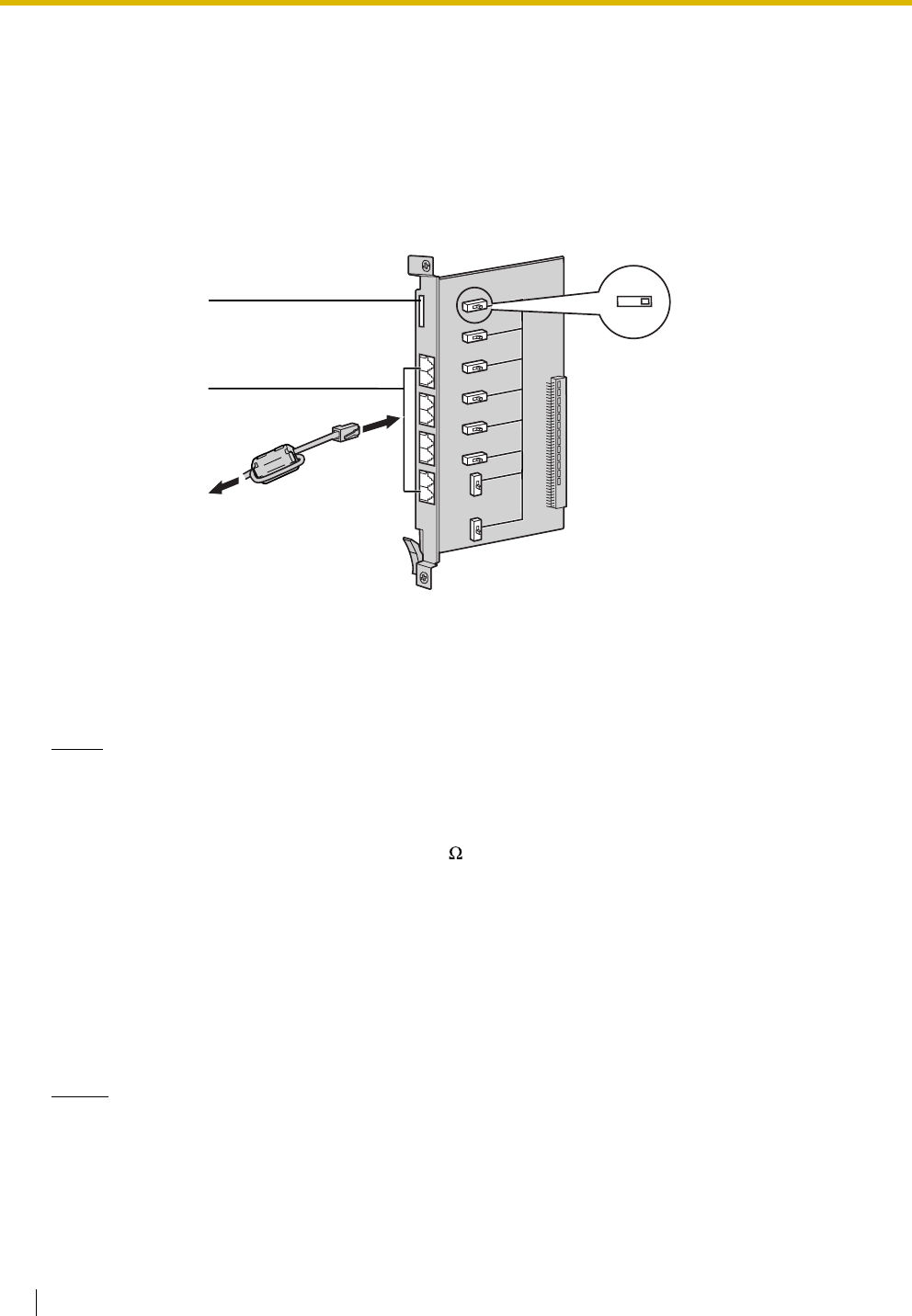
2.4 Information about the Trunk Cards
90 Installation Manual
2.4.8 BRI4 Card (KX-TDA0284) and BRI8 Card (KX-TDA0288)
Function
Accessories and User-supplied Items
Accessories (included): Ferrite core(s) × 1 (BRI4 card) or 2 (BRI8 card)
User-supplied (not included): RJ45 connector
Notes
• LINE 5 to LINE 8 are for BRI8 card only.
• When connecting these optional service cards to the trunk, connect through an NT1; do not
connect to the U interface of the trunk directly.
• These optional service cards have 100 of terminal resistance. For use in point to multi-point
connection, the cards must be placed at the end of the bus.
• When connecting the RJ45 connector, attach the included ferrite core. Refer to "2.2.9 Attaching a
Ferrite Core".
• These optional service cards can be used for either trunk or extension connection, by setting the
A/B switch or using the connector with appropriate pin assignments.
• For details about power failure transfer, refer to "2.12.1 Power Failure Connections".
• To confirm the trunk connection, refer to "Confirming the Trunk Connection" in "2.13.1 Starting the
Hybrid IP-PBX".
Notice
If the connected ISDN terminal has no external power source, make sure that the power is supplied
from the BRI4/BRI8 card by programming the Hybrid IP-PBX accordingly.
However, if there is an external power source to the terminal, make sure that there is no power supplied
to the terminal from the BRI4/BRI8 card. Failure to do so may cause damage to the power supply circuit
of the BRI4/BRI8 card or the terminal.
BRI4: 4-port ISDN Basic Rate Interface card with 1 power failure transfer port. EURO-ISDN/ETSI
compliant.
BRI8: 8-port ISDN Basic Rate Interface card with 1 power failure transfer port. EURO-ISDN/ETSI
compliant.
LEDs
RJ45
(LINE 1 to LINE 8)
AB
To NT1/
Extension
2.4 Information about the Trunk Cards
Installation Manual 91
Switch Settings
Pin Assignments
RJ45 Connector for Trunk Use
RJ45 Connector for Extension Use
LED Indications
Switch Type Usage and Status Definition
A/B Slide Select A (default) for trunk or B for extension use.
No. Signal Name Level [V] Function
1-2 Reserved – –
3 TX1 (+) Transmit data 1
4 RX2 (+) Receive data 2
5 RX1 (-) Receive data 1
6 TX2 (-) Transmit data 2
7-8 Reserved – –
No. Signal Name Level [V] Function
1-2 Reserved – –
3 RX2 (+) Receive data 2
4 TX1 (+) Transmit data 1
5 TX2 (-) Transmit data 2
6 RX1 (-) Receive data 1
7-8 Reserved – –
Indication Colour Description
CARD STATUS Green/Red Card status indication
• OFF: Power Off
• Green ON: Normal (all ports are idle)
• Green Flashing (60 times per minute): Normal (a port is in use)
• Red ON: Fault (includes reset)
• Red Flashing (60 times per minute): Out of Service
8
1
8
1
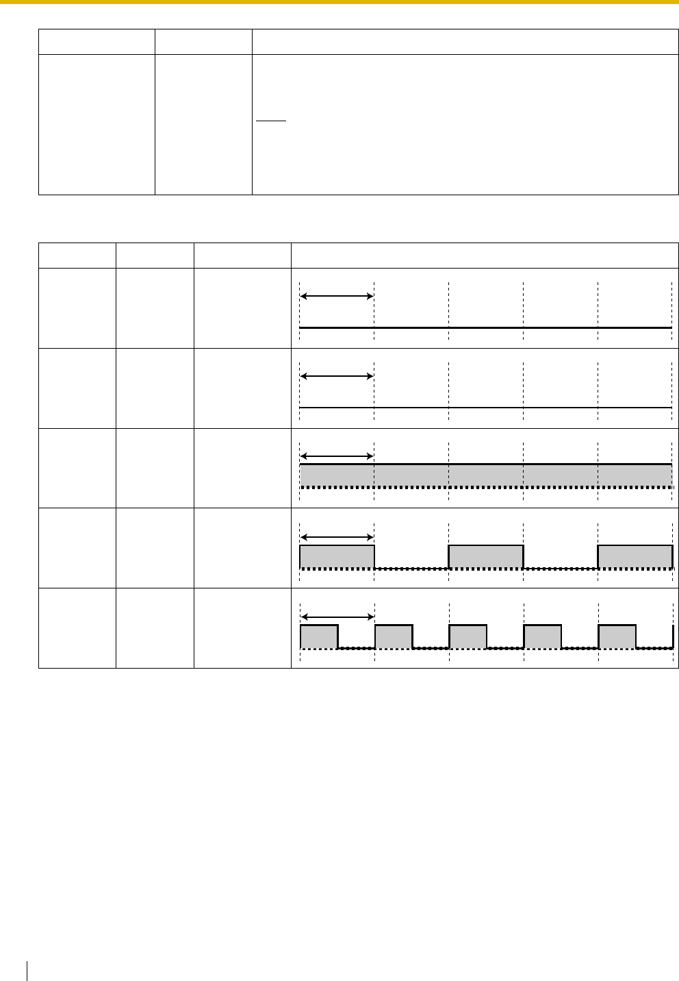
2.4 Information about the Trunk Cards
92 Installation Manual
LINE LED Pattern
Layer 1: ON (Synchronous)
Layer 2: ON (Link established)/OFF (Link not established)
Master Clock: ON (Master)/OFF (Slave)
LINE 8
LINE 7
LINE 6
LINE 5
LINE 4
LINE 3
LINE 2
LINE 1
Green Line status indication (LINE 1 to LINE 8):
Refer to "LINE LED Pattern" below for details.
Note
LINE 5 to LINE 8 are for BRI8 card only.
Layer 1 Layer 2 Master Clock LED Pattern
OFF OFF OFF
ON OFF OFF
ON ON OFF
ON OFF ON
ON ON ON
Indication Colour Description
1 s
1 s
1 s
1 s
1 s
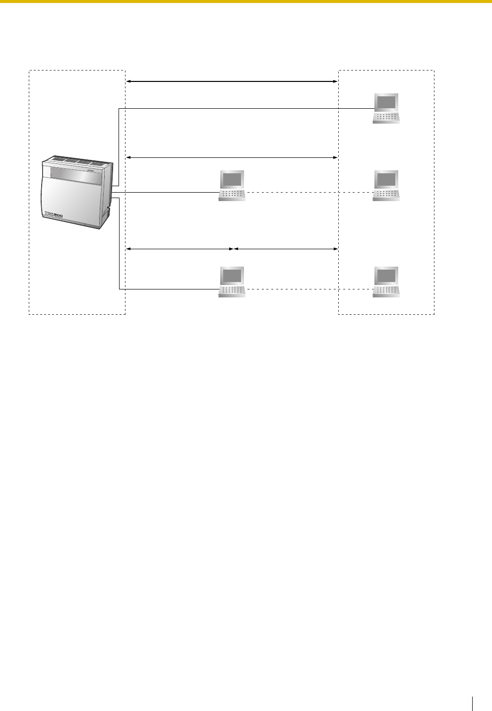
2.4 Information about the Trunk Cards
Installation Manual 93
Maximum Cabling Distance of S0 Bus Connection
The maximum length of the extension cable that connects the Hybrid IP-PBX and the ISDN terminal
equipment (TE) is shown below:
CAT 5: Under 1000 m
TE
Point-to-Point
Expansion
Point-to-Multipoint
Point-to-Multipoint
TE 1 TE 8
TE 8TE 1
CAT 5: Under 150 m
CAT 5: Under 500 m CAT 5: Under 50 m
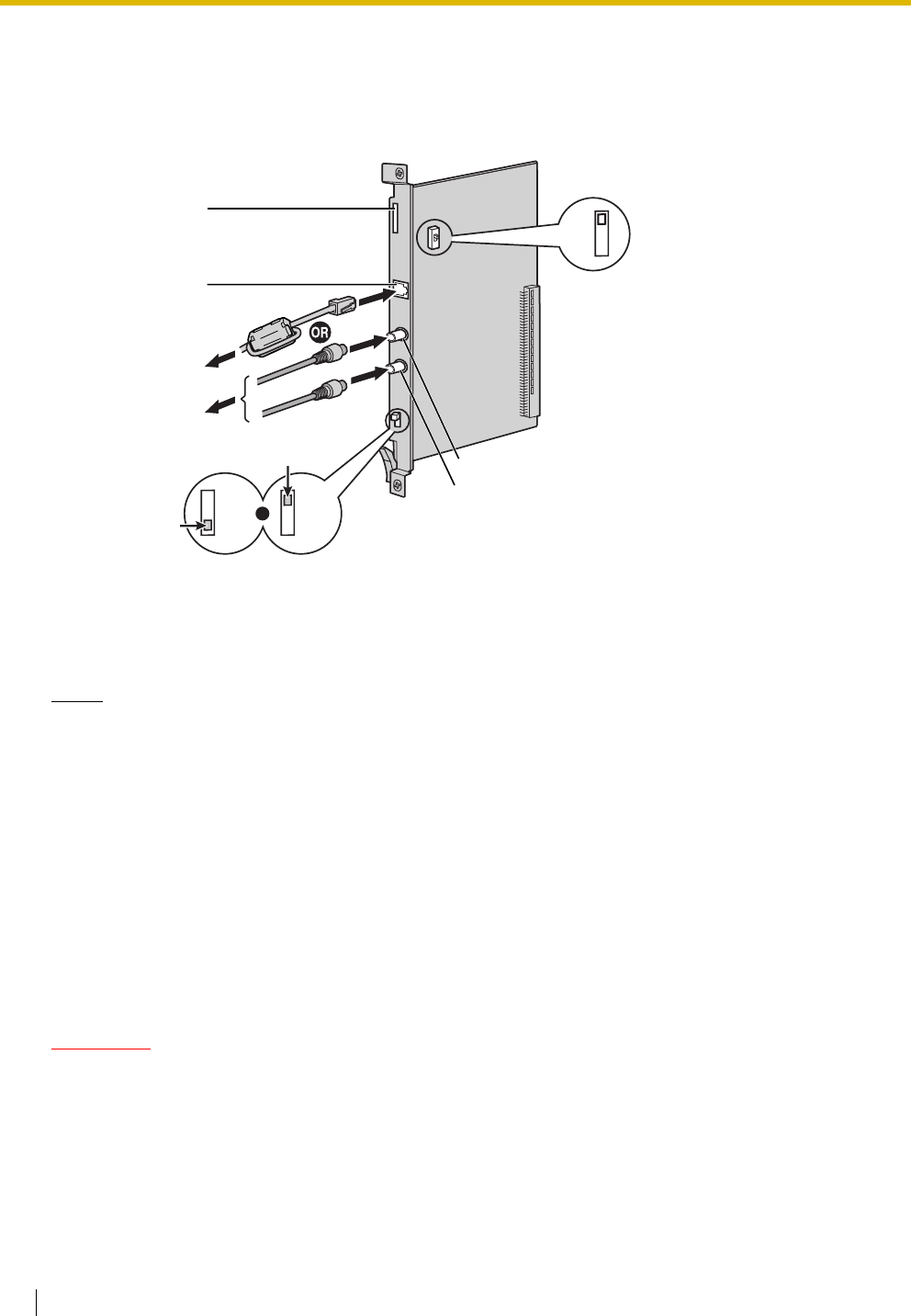
2.4 Information about the Trunk Cards
94 Installation Manual
2.4.9 PRI30 Card (KX-TDA0290CE/CJ)
Function
1-port ISDN Primary Rate Interface card (30B channels). EURO-ISDN/ETSI compliant.
Accessories and User-supplied Items
Accessories (included): Ferrite core × 1
User-supplied (not included): RJ45 or BNC connector
Notes
• In some countries/areas, this optional service card must not be connected to the Public Switched
Telephone Network.
• When connecting this optional service card to the trunk, connect through an NT1; do not connect
to the U interface of the trunk directly.
• Use only 1 type of connector (RJ45 or BNC) for connection; RJ45 and BNC cannot be used
simultaneously.
• When connecting the RJ45 connector, attach the included ferrite core. Refer to "2.2.9 Attaching a
Ferrite Core".
• This optional service card can be used for either trunk or extension connection, by setting the A/B
switch or using the connector with appropriate pin assignments.
• To confirm the trunk connection, refer to "Confirming the Trunk Connection" in "2.13.1 Starting the
Hybrid IP-PBX".
CAUTION
PRI ports are SELV ports and should only be connected to SELV services.
LEDs
RJ45
To NT1/Extension
To N T 1
/
Extension
BNC (TX)
BNC (RX)
AB
For RJ45
For BNC
120Ω
75Ω
120Ω
75Ω
OR
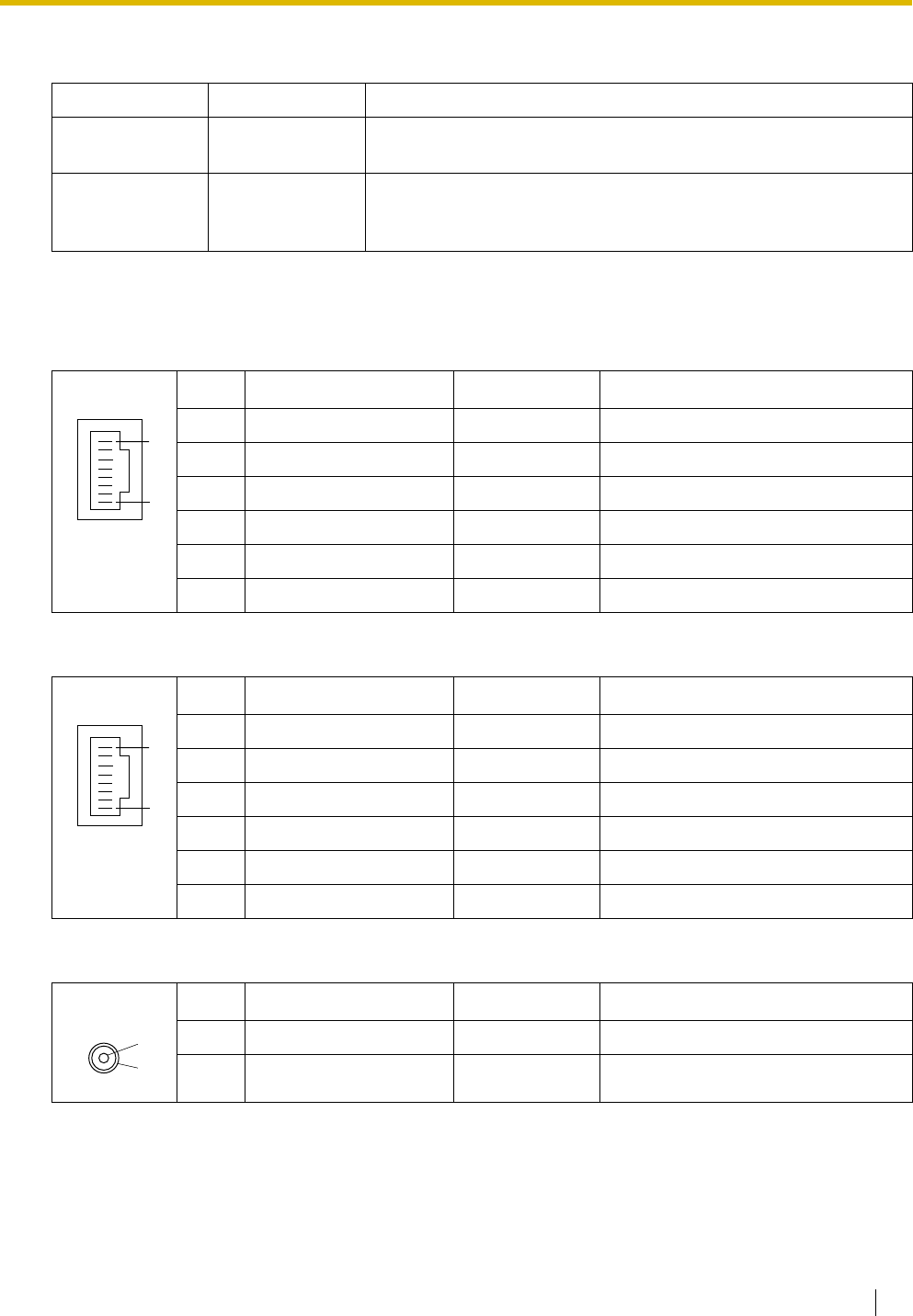
2.4 Information about the Trunk Cards
Installation Manual 95
Switch Settings
Pin Assignments
RJ45 Connector for Trunk Use
RJ45 Connector for Extension Use
BNC (coaxial) Connector (TX)
Switch Type Usage and Status Definition
Termination Slide Select 120 Ω (default) or 75 Ω to match the connector type to be
used.
A/B Slide When using an RJ45 connector, select A (default) for trunk or B for
extension use.
When using BNC connectors, make sure that A is selected.
No. Signal Name Level [V] Function
1 RX+ (+) Receive data (+)
2 RX- (-) Receive data (-)
3 Reserved – –
4 TX- (-) Transmit data (-)
5 TX+ (+) Transmit data (+)
6-8 Reserved – –
No. Signal Name Level [V] Function
1 TX- (-) Transmit data (-)
2 TX+ (+) Transmit data (+)
3 Reserved – –
4 RX+ (+) Receive data (+)
5 RX- (-) Receive data (-)
6-8 Reserved – –
No. Signal Name Level [V] Function
1 TX+ (+) Transmit data (+)
2 TX- (-) Transmit data (-)
8
1
8
1
1
2
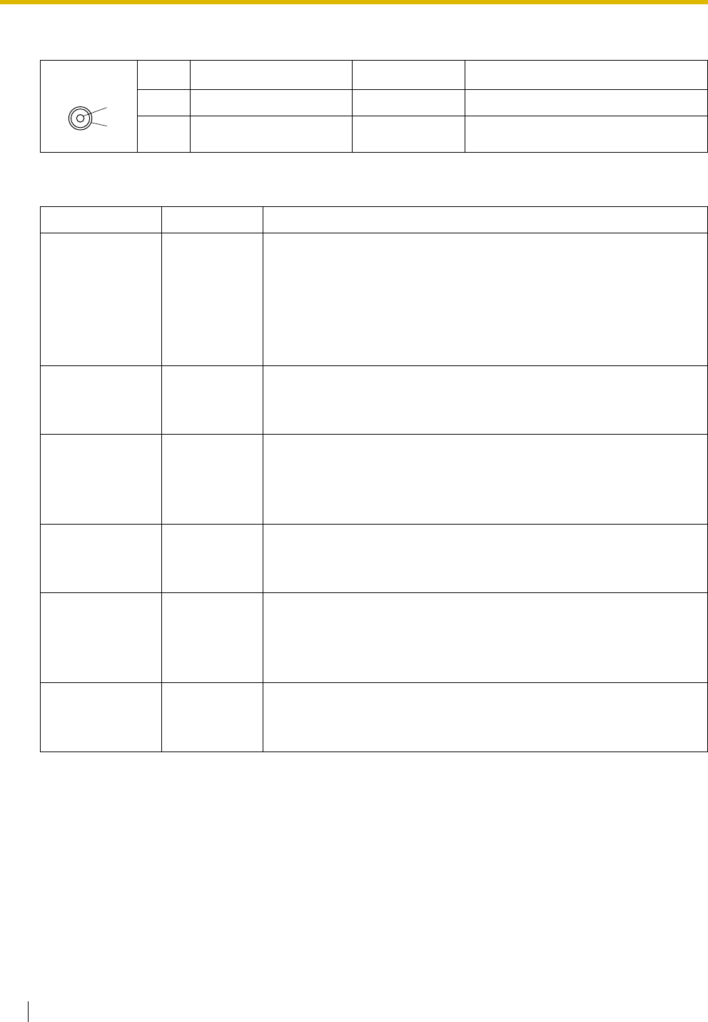
2.4 Information about the Trunk Cards
96 Installation Manual
BNC (coaxial) Connector (RX)
LED Indications
No. Signal Name Level [V] Function
1 RX- (-) Receive data (-)
2 RX+ (+) Receive data (+)
Indication Colour Description
CARD STATUS Green/Red Card status indication
• OFF: Power Off
• Green ON: Normal (all ports are idle)
• Green Flashing (60 times per minute): Normal (a port is in use)
• Red ON: Fault (includes reset)
• Red Flashing (60 times per minute): Out of Service
SYNC-ERR Red Non-synchronisation status indication
• OFF: Normal
• ON: Out of synchronisation
RAI Red RAI signal status indication
• OFF: Normal
•ON: Alarm (Clock Slave)
• Flashing (60 times per minute): Alarm (Clock Master)
AIS Red AIS status indication
• OFF: Normal
•ON: Alarm
SYNC Green Synchronisation status indication
• OFF: Not synchronised
• ON: Synchronised
• Flashing (60 times per minute): Synchronised (Clock Master)
D-LINK Green Data link status indication
• OFF: Not established
• ON: Established
1
2
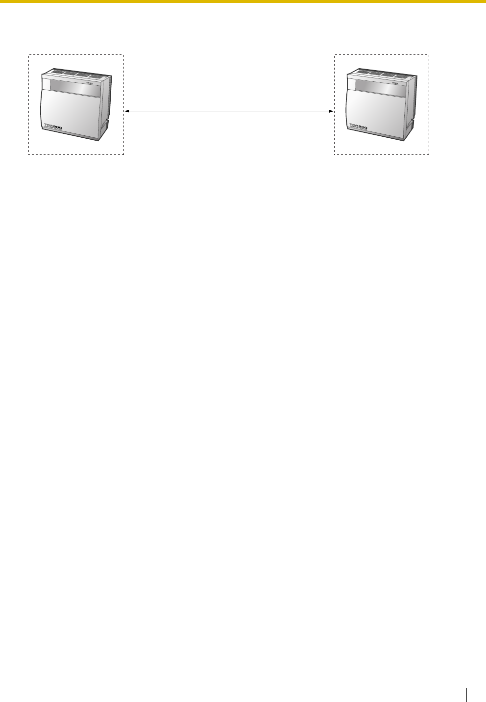
2.4 Information about the Trunk Cards
Installation Manual 97
Maximum Cabling Distance of Extension Connection
The maximum length of the extension cable that connects the PRI30 cards is shown below:
Diameter Maximum Distance
0.5 mm: 200 m
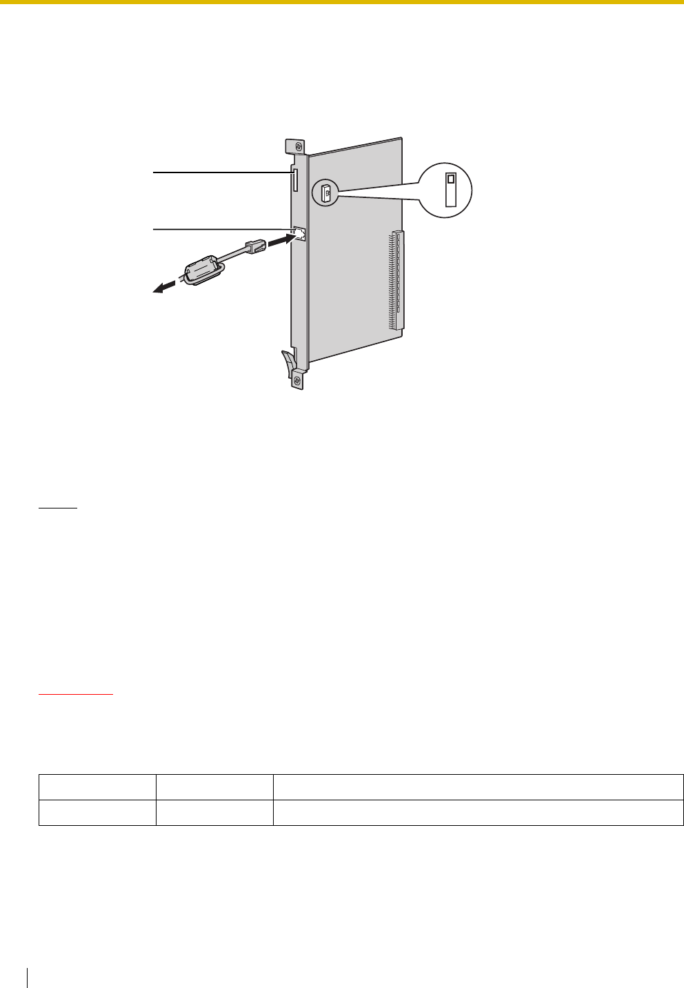
2.4 Information about the Trunk Cards
98 Installation Manual
2.4.10 PRI23 Card (KX-TDA0290)
Function
1-port ISDN Primary Rate Interface card (23B channels). NI (North American standard ISDN protocol)
compliant.
Accessories and User-supplied Items
Accessories (included): Ferrite core × 1
User-supplied (not included): RJ45 connector
Notes
• When connecting this optional service card to the trunk, connect through an NT1; do not connect
to the U interface of the trunk directly.
• When connecting the RJ45 connector, attach the included ferrite core (except in Canada, where
the ferrite core is not necessarily required). Refer to "2.2.9 Attaching a Ferrite Core".
• This optional service card can be used for either trunk or extension connection, by setting the A/B
switch or using the connector with appropriate pin assignments.
• To confirm the trunk connection, refer to "Confirming the Trunk Connection" in "2.13.1 Starting the
Hybrid IP-PBX".
CAUTION
PRI ports are SELV ports and should only be connected to SELV services.
Switch Settings
Switch Type Usage and Status Definition
A/B Slide Select A (default) for trunk or B for extension use.
LEDs
RJ45
To NT1/
Extension
AB

2.4 Information about the Trunk Cards
Installation Manual 99
Pin Assignments
RJ45 Connector for Trunk Use
RJ45 Connector for Extension Use
LED Indications
No. Signal Name Level [V] Function
1 RX+ (+) Receive data (+)
2 RX- (-) Receive data (-)
3 Reserved – –
4 TX- (-) Transmit data (-)
5 TX+ (+) Transmit data (+)
6-8 Reserved – –
No. Signal Name Level [V] Function
1 TX- (-) Transmit data (-)
2 TX+ (+) Transmit data (+)
3 Reserved – –
4 RX+ (+) Receive data (+)
5 RX- (-) Receive data (-)
6-8 Reserved – –
Indication Colour Description
CARD STATUS Green/Red Card status indication
• OFF: Power Off
• Green ON: Normal (all ports are idle)
• Green Flashing (60 times per minute): Normal (a port is in use)
• Red ON: Fault (includes reset)
• Red Flashing (60 times per minute): Out of Service
SYNC-ERR Red Non-synchronisation status indication
• OFF: Normal
• ON: Out of synchronisation
RAI Red RAI signal status indication
• OFF: Normal
•ON: Alarm (Clock Slave)
• Flashing (60 times per minute): Alarm (Clock Master)
AIS Red AIS status indication
• OFF: Normal
•ON: Alarm
8
1
8
1
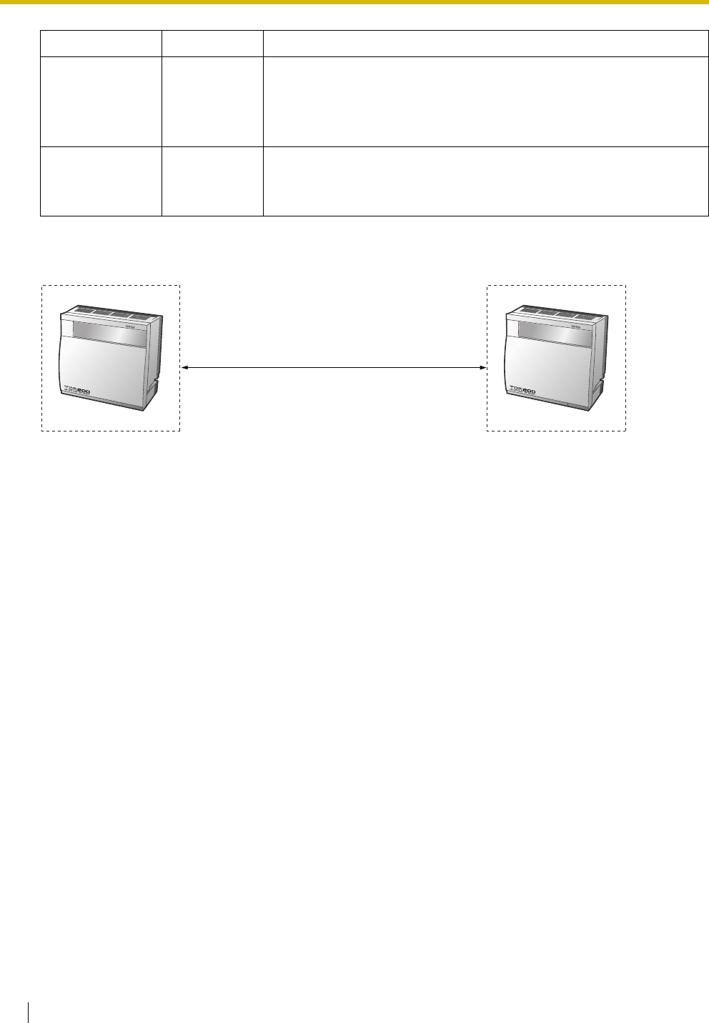
2.4 Information about the Trunk Cards
100 Installation Manual
Maximum Cabling Distance of Extension Connection
The maximum length of the extension cable that connects the PRI23 cards is shown below:
SYNC Green Synchronisation status indication
• OFF: Not synchronised
• ON: Synchronised
• Flashing (60 times per minute): Synchronised (Clock Master)
D-LINK Green Data link status indication
• OFF: Not established
• ON: Established
Indication Colour Description
Diameter Maximum Distance
0.5 mm: 200 m
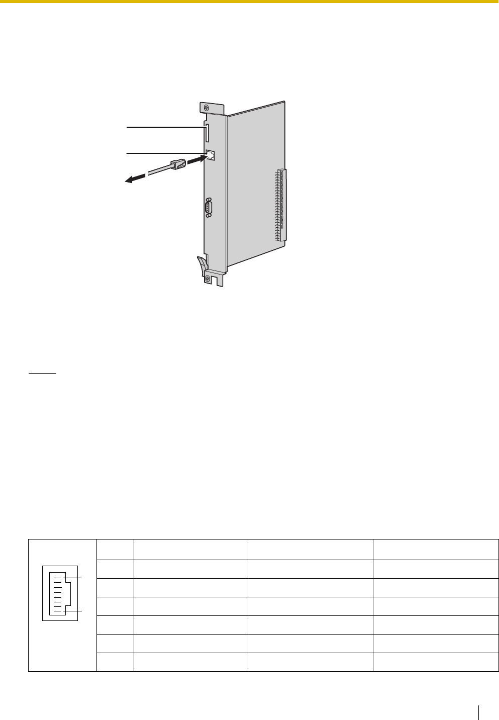
2.4 Information about the Trunk Cards
Installation Manual 101
2.4.11 IP-GW4 Card (KX-TDA0480)
Function
4-channel VoIP gateway card. Compliant with VoIP H.323 V.2 protocol, and ITU-T G.729a and G.723.1
CODEC methods. G3 fax support.
Accessories and User-supplied Items
Accessories (included): CD-ROM (including PC programming software and documentation) × 1
User-supplied (not included): RJ45 connector
Notes
• The maximum length of the cable to be connected to this optional service card is 100 m.
• The IP-GW4 card occupies the space of 2 free slots when it is installed in the Hybrid IP-PBX.
• For programming instructions and other information about the IP-GW4 card, refer to the
documentation for the IP-GW4 card. To programme the IP-GW4 card, use the PC programming
software designed for the IP-GW4 card.
• To confirm the trunk connection, refer to "Confirming the Trunk Connection" in "2.13.1 Starting the
Hybrid IP-PBX".
Pin Assignments
RJ45 Connector (10BASE-T)
No. Signal Name Input (I)/Output (O) Function
1 TPO+ O Transmit data+
2 TPO- O Transmit data-
3TPI+ I Receive data+
4-5 Reserved – –
6TPI- I Receive data-
7-8 Reserved – –
RJ45 (10BASE-T)
LEDs
To private IP network
8
1

2.4 Information about the Trunk Cards
102 Installation Manual
LED Indications
Indication Colour Description
CARD STATUS Green/Red Card status indication
• OFF: Power Off
• Green ON: Normal (all ports are idle)
• Green Flashing (60 times per minute): Normal (a port is in use)
• Red ON: Fault (includes reset)
• Red Flashing (60 times per minute): Out of Service
ONLINE Green On-line status indication
• ON: On-line mode
• Flashing: Emergency maintenance mode
ALARM Red Alarm indication
• OFF: Normal
•ON: Alarm
IAM BUSY Green Busy status indication
• OFF: Not used
• ON: At least one line is used
LINK Green Link status indication
• OFF: Connection error
• ON: Normal connection
DATA Green Data transmission indication
• OFF: No data transmitted
• ON: Data transmitting
COL Green Data collision indication
• OFF: No data collision
• ON: Data collision
SIOSEL Green Serial maintenance port status indication
• OFF: CPU power port used (maintenance port not available)
• ON: Maintenance port available
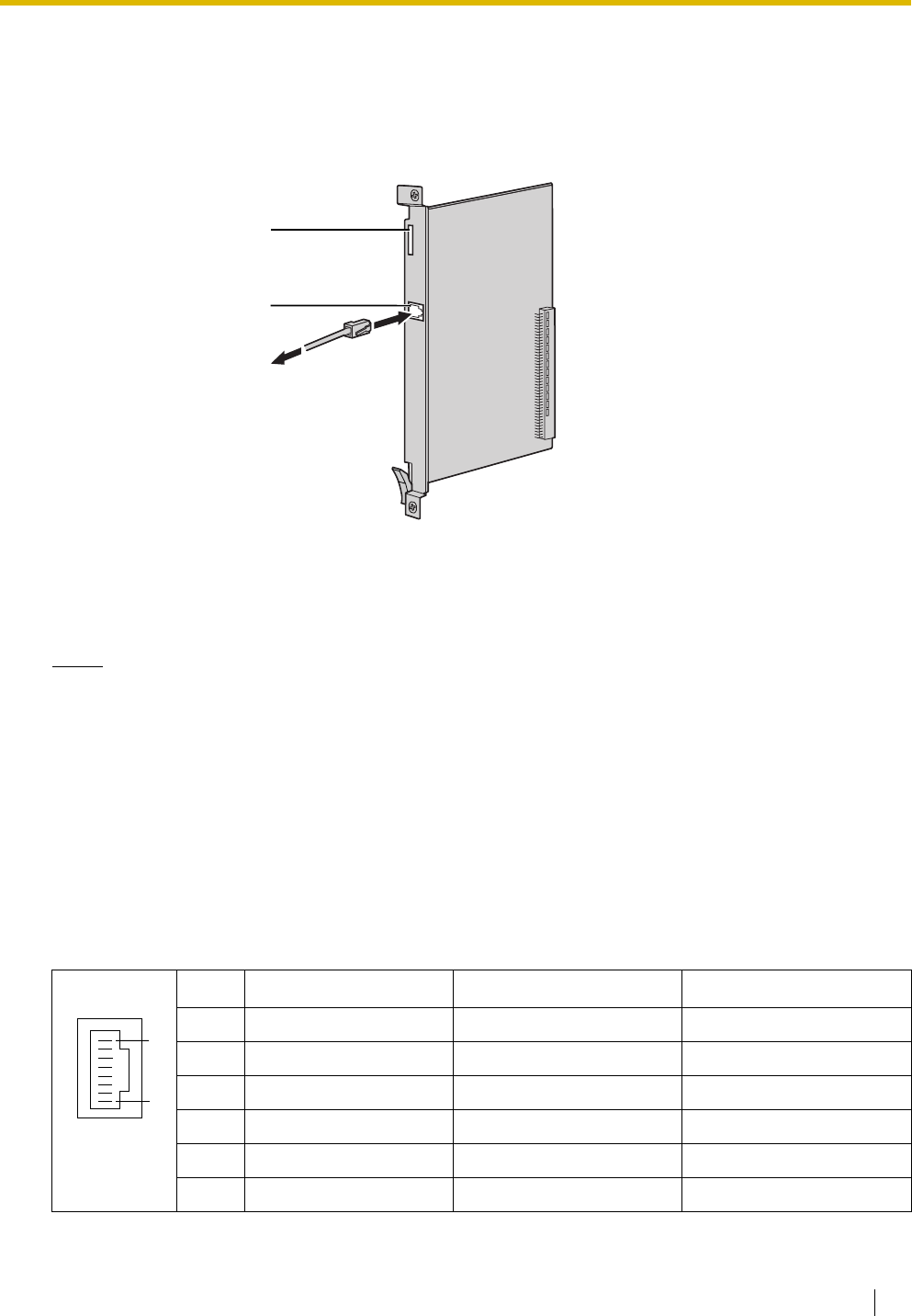
2.4 Information about the Trunk Cards
Installation Manual 103
2.4.12 IP-GW4E Card (KX-TDA0484)
Function
4-channel VoIP gateway card. Compliant with VoIP H.323 V.2 protocol, and ITU-T G.729a, G.723.1, and
G.711 CODEC methods.
Accessories and User-supplied Items
Accessories (included): CD-ROM (including documentation for web programming) × 1
User-supplied (not included): RJ45 connector
Notes
• The maximum length of the cable to be connected to this optional service card is 100 m.
• The IP-GW4E card occupies the space of only 1 free slot when it is installed in the Hybrid IP-PBX.
• For programming instructions and other information about the IP-GW4E card, refer to the
documentation for the IP-GW4E card. To programme the IP-GW4E card, use the web
programming designed for the IP-GW4E card.
• To confirm the trunk connection, refer to "Confirming the Trunk Connection" in "2.13.1 Starting the
Hybrid IP-PBX".
Pin Assignments
RJ45 Connector (10BASE-T/100BASE-TX)
No. Signal Name Input (I)/Output (O) Function
1 TPO+ O Transmit data+
2 TPO- O Transmit data-
3TPI+ I Receive data+
4-5 Reserved – –
6TPI- I Receive data-
7-8 Reserved – –
LEDs
RJ45
(10BASE-T/100BASE-TX)
To private IP network
8
1

2.4 Information about the Trunk Cards
104 Installation Manual
LED Indications
Indication Colour Description
CARD STATUS Green/Red Card status indication
• OFF: Power Off
• Green ON: Normal (all ports are idle)
• Green Flashing (60 times per minute): Normal (a port is in use)
• Red ON: Fault (includes reset)
• Red Flashing (60 times per minute): Out of Service
ONLINE Green On-line status indication
• ON: On-line mode
• OFF: Off-line mode
• Flashing: Maintenance mode
Note
If the LINK indicator is OFF, the ONLINE indicator will also be
OFF.
ALARM Red Alarm indication
• OFF: Normal
•ON: Alarm
VoIP BUSY Green VoIP (H.323) process indication
• OFF: VoIP process inactive
• ON: VoIP process active
LINK Green Link status indication
• OFF: Connection error
• ON: Normal connection
DATA Green Data transmission indication
• OFF: No data transmitted
• ON: Data transmitting
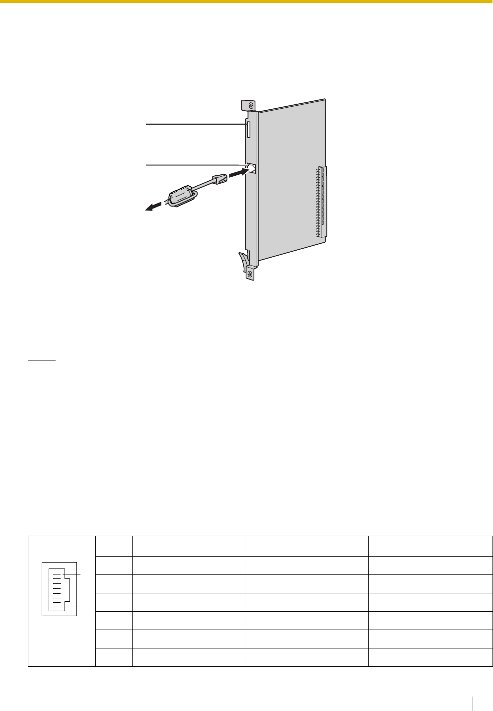
2.4 Information about the Trunk Cards
Installation Manual 105
2.4.13 IP-GW16 Card (KX-TDA0490)
Function
16-channel VoIP gateway card. Compliant with VoIP H.323 V.2 protocol, and ITU-T G.729a, G.723.1, and
G.711 CODEC methods.
Accessories and User-supplied Items
Accessories (included): Ferrite core × 1, CD-ROM (including documentation for web programming) × 1
User-supplied (not included): RJ45 connector
Notes
• The maximum length of the cable to be connected to this optional service card is 100 m.
• When connecting the RJ45 connector, attach the included ferrite core. Refer to "2.2.9 Attaching a
Ferrite Core".
• For programming instructions and other information about the IP-GW16 card, refer to the
documentation for the IP-GW16 card. To programme the IP-GW16 card, use the web programming
designed for the IP-GW16 card.
• To confirm the trunk connection, refer to "Confirming the Trunk Connection" in "2.13.1 Starting the
Hybrid IP-PBX".
Pin Assignments
RJ45 Connector (10BASE-T/100BASE-TX)
No. Signal Name Input (I)/Output (O) Function
1 TPO+ O Transmit data+
2 TPO- O Transmit data-
3TPI+ I Receive data+
4-5 Reserved – –
6TPI- I Receive data-
7-8 Reserved – –
LEDs
RJ45
(10BASE-T/100BASE-TX
Full Duplex)
To private IP network
8
1

2.4 Information about the Trunk Cards
106 Installation Manual
LED Indications
Indication Colour Description
CARD STATUS Green/Red Card status indication
• OFF: Power Off
• Green ON: Normal (all ports are idle)
• Green Flashing (60 times per minute): Normal (a port is in use)
• Red ON: Fault (includes reset)
• Red Flashing (60 times per minute): Out of Service
ONLINE Green On-line status indication
• ON: On-line mode
• OFF: Off-line mode
• Flashing: Maintenance mode
Note
If the LINK indicator is OFF, the ONLINE indicator will also be
OFF.
ALARM Red Alarm indication
• OFF: Normal
•ON: Alarm
VoIP BUSY Green VoIP (H.323) process indication
• OFF: VoIP process inactive
• ON: VoIP process active
LINK Green Link status indication
• OFF: Connection error
• ON: Normal connection
DATA Green Data transmission indication
• OFF: No data transmitted
• ON: Data transmitting
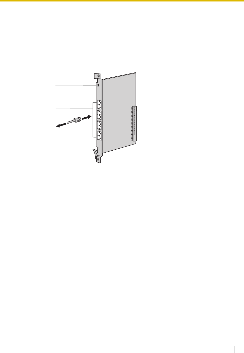
2.5 Information about the Extension Cards
Installation Manual 107
2.5 Information about the Extension Cards
2.5.1 CSIF4 Card (KX-TDA0143) and CSIF8 Card (KX-TDA0144)
Function
CSIF4: 4-port CS interface card for 4 CSs.
CSIF8: 8-port CS interface card for 8 CSs.
Accessories and User-supplied Items
Accessories (included): none
User-supplied (not included): RJ45 connector
Notes
• LINE 5 to LINE 8 are for CSIF8 card only.
• When using the CSIF4 card, please note that the Hybrid IP-PBX software will recognise the CSIF4
card as the CSIF8 card. As a result, 8 cell stations may appear to be available; however, only 4 cell
stations are supported by the CSIF4 card.
• For details about connecting the CS, refer to "2.8.7 Connecting a Cell Station to the Hybrid IP-PBX"
in "2.8 Connection of DECT Portable Stations" or "2.9.7 Connecting a Cell Station to the Hybrid IP-
PBX" in "2.9 Connection of 2.4 GHz Portable Stations".
RJ45
(LINE 1 to LINE 8)
LED
To C S
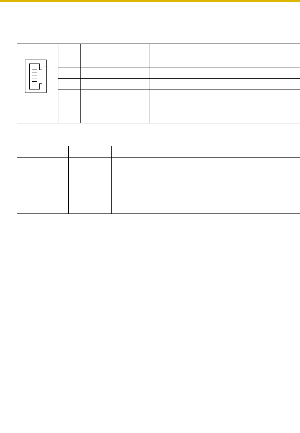
2.5 Information about the Extension Cards
108 Installation Manual
Pin Assignments
RJ45 Connector
LED Indications
No. Signal Name Function
1-2 Reserved –
3 D1 Data port (High)
4 POWH Power (High)
5 POWL Power (Low)
6 D2 Data port (Low)
7-8 Reserved –
Indication Colour Description
CARD STATUS Green/Red Card status indication
• OFF: Power Off
• Green ON: Normal (all ports are idle)
• Green Flashing (60 times per minute): Normal (a port is in use)
• Red ON: Fault (includes reset)
• Red Flashing (60 times per minute): Out of Service
8
1
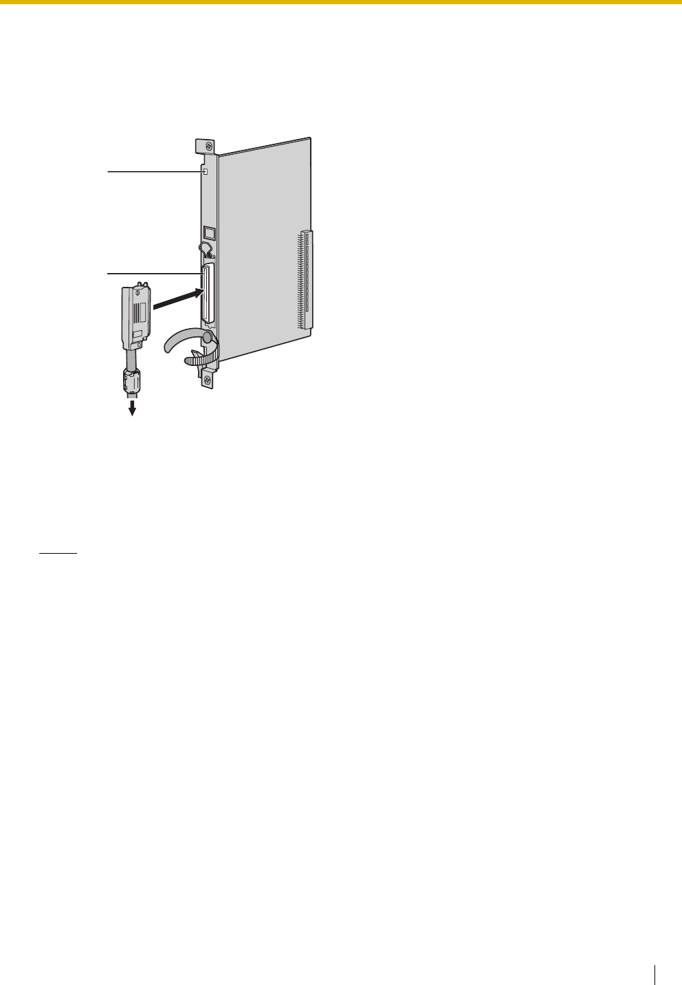
2.5 Information about the Extension Cards
Installation Manual 109
2.5.2 DHLC8 Card (KX-TDA0170)
Function
8-port digital hybrid extension card for DPTs, APTs, SLTs, DSS consoles, and PT-interface CSs, with 2
power failure transfer (PFT) ports.
Accessories and User-supplied Items
Accessories (included): Screws × 2, Ferrite core × 1
User-supplied (not included): Amphenol connector
Notes
• Attach the included ferrite core to the cable. Refer to "2.2.9 Attaching a Ferrite Core".
• To connect the Amphenol connector, refer to "2.2.10 Fastening Amphenol Connector".
• For details about power failure transfer, refer to "2.12.1 Power Failure Connections".
LED
Amphenol
To extensions

2.5 Information about the Extension Cards
110 Installation Manual
Pin Assignments
Amphenol Connector
No. Signal Name Function No. Signal Name Function
1 RA SLT Ring port 1 26 TA SLT Tip port 1
2 D2A PT Data port 1 (Low) 27 D1A PT Data port 1 (High)
3 Reserved – 28 Reserved –
4 RB SLT Ring port 2 29 TB SLT Tip port 2
5 D2B PT Data port 2 (Low) 30 D1B PT Data port 2 (High)
6 Reserved – 31 Reserved –
7 RC SLT Ring port 3 32 TC SLT Tip port 3
8 D2C PT Data port 3 (Low) 33 D1C PT Data port 3 (High)
9 Reserved – 34 Reserved –
10 RD SLT Ring port 4 35 TD SLT Tip port 4
11 D2D PT Data port 4 (Low) 36 D1D PT Data port 4 (High)
12 Reserved – 37 Reserved –
13 RE SLT Ring port 5 38 TE SLT Tip port 5
14 D2E PT Data port 5 (Low) 39 D1E PT Data port 5 (High)
15 Reserved – 40 Reserved –
16 RF SLT Ring port 6 41 TF SLT Tip port 6
17 D2F PT Data port 6 (Low) 42 D1F PT Data port 6 (High)
18 Reserved – 43 Reserved –
19 RG SLT Ring port 7 44 TG SLT Tip port 7
20 D2G PT Data port 7 (Low) 45 D1G PT Data port 7 (High)
21 Reserved – 46 Reserved –
22 RH SLT Ring port 8 47 TH SLT Tip port 8
23 D2H PT Data port 8 (Low) 48 D1H PT Data port 8 (High)
24-
25
Reserved – 49-
50
Reserved –
50 25
26 1

2.5 Information about the Extension Cards
Installation Manual 111
LED Indications
Indication Colour Description
CARD STATUS Green/
Orange/Red
Card status indication
• OFF: Power Off
• Green ON: Normal (all ports are idle)
• Green Flashing (60 times per minute): Normal (a port is in use)
• Orange Flashing: Detection of PT-interface CS connection (when
starting up the PT-interface CS)
• Red ON: Fault (includes reset)
• Red Flashing (60 times per minute): Out of Service

2.5 Information about the Extension Cards
112 Installation Manual
2.5.3 DLC8 Card (KX-TDA0171)
Function
8-port digital extension card for DPTs, DSS consoles, and PT-interface CSs.
Accessories and User-supplied Items
Accessories (included): Screws × 2, Ferrite core × 1
User-supplied (not included): Amphenol connector
Notes
• Attach the included ferrite core to the cable. Refer to "2.2.9 Attaching a Ferrite Core".
• To connect the Amphenol connector, refer to "2.2.10 Fastening Amphenol Connector".
LED
Amphenol
To extensions

2.5 Information about the Extension Cards
Installation Manual 113
Pin Assignments
Amphenol Connector
LED Indications
No. Signal Name Function No. Signal Name Function
1 Reserved – 26 Reserved –
2 D2A Data port 1 (Low) 27 D1A Data port 1 (High)
3-4 Reserved – 28-29 Reserved –
5 D2B Data port 2 (Low) 30 D1B Data port 2 (High)
6-7 Reserved – 31-32 Reserved –
8 D2C Data port 3 (Low) 33 D1C Data port 3 (High)
9-10 Reserved – 34-35 Reserved –
11 D2D Data port 4 (Low) 36 D1D Data port 4 (High)
12-13 Reserved – 37-38 Reserved –
14 D2E Data port 5 (Low) 39 D1E Data port 5 (High)
15-16 Reserved – 40-41 Reserved –
17 D2F Data port 6 (Low) 42 D1F Data port 6 (High)
18-19 Reserved – 43-44 Reserved –
20 D2G Data port 7 (Low) 45 D1G Data port 7 (High)
21-22 Reserved – 46-47 Reserved –
23 D2H Data port 8 (Low) 48 D1H Data port 8 (High)
24-25 Reserved – 49-50 Reserved –
Indication Colour Description
CARD STATUS Green/
Orange/Red
Card status indication
• OFF: Power Off
• Green ON: Normal (all ports are idle)
• Green Flashing (60 times per minute): Normal (a port is in use)
• Orange Flashing: Detection of PT-interface CS connection (when
starting up the PT-interface CS)
• Red ON: Fault (includes reset)
• Red Flashing (60 times per minute): Out of Service
50 25
26 1

2.5 Information about the Extension Cards
114 Installation Manual
2.5.4 DLC16 Card (KX-TDA0172)
Function
16-port digital extension card for DPTs, DSS consoles, and PT-interface CSs.
Accessories and User-supplied Items
Accessories (included): Screws × 2, Ferrite core × 1
User-supplied (not included): Amphenol connector
Notes
• Attach the included ferrite core to the cable. Refer to "2.2.9 Attaching a Ferrite Core".
• To connect the Amphenol connector, refer to "2.2.10 Fastening Amphenol Connector".
LED
Amphenol
To extensions
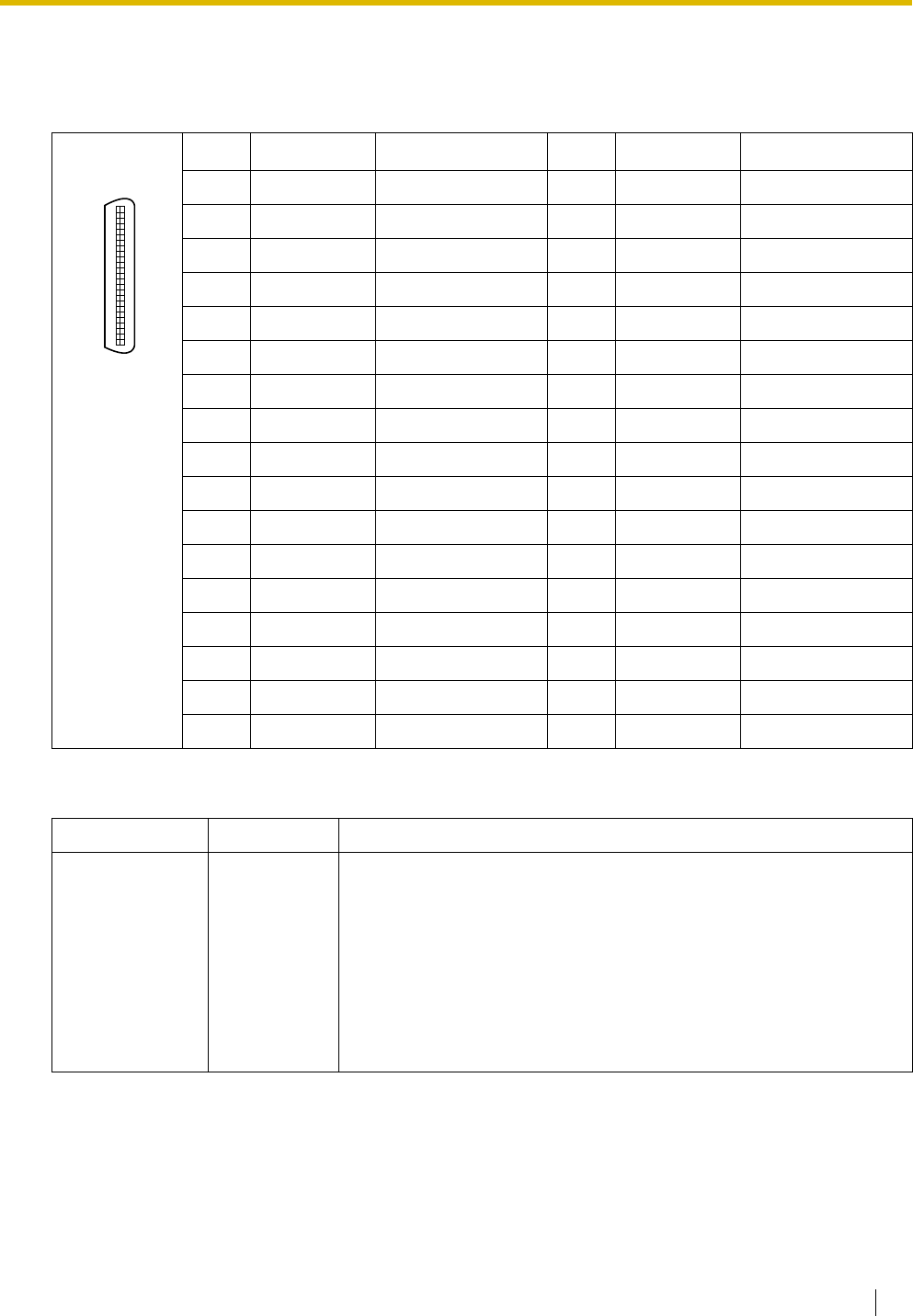
2.5 Information about the Extension Cards
Installation Manual 115
Pin Assignments
Amphenol Connector
LED Indications
No. Signal Name Function No. Signal Name Function
1 D2A Data port 1 (Low) 26 D1A Data port 1 (High)
2 D2B Data port 2 (Low) 27 D1B Data port 2 (High)
3 D2C Data port 3 (Low) 28 D1C Data port 3 (High)
4 D2D Data port 4 (Low) 29 D1D Data port 4 (High)
5 D2E Data port 5 (Low) 30 D1E Data port 5 (High)
6 D2F Data port 6 (Low) 31 D1F Data port 6 (High)
7 D2G Data port 7 (Low) 32 D1G Data port 7 (High)
8 D2H Data port 8 (Low) 33 D1H Data port 8 (High)
9 D2I Data port 9 (Low) 34 D1I Data port 9 (High)
10 D2J Data port 10 (Low) 35 D1J Data port 10 (High)
11 D2K Data port 11 (Low) 36 D1K Data port 11 (High)
12 D2L Data port 12 (Low) 37 D1L Data port 12 (High)
13 D2M Data port 13 (Low) 38 D1M Data port 13 (High)
14 D2N Data port 14 (Low) 39 D1N Data port 14 (High)
15 D2O Data port 15 (Low) 40 D1O Data port 15 (High)
16 D2P Data port 16 (Low) 41 D1P Data port 16 (High)
17-25 Reserved – 42-50 Reserved –
Indication Colour Description
CARD STATUS Green/
Orange/Red
Card status indication
• OFF: Power Off
• Green ON: Normal (all ports are idle)
• Green Flashing (60 times per minute): Normal (a port is in use)
• Orange Flashing: Detection of PT-interface CS connection (when
starting up the PT-interface CS)
• Red ON: Fault (includes reset)
• Red Flashing (60 times per minute): Out of Service
50 25
26 1
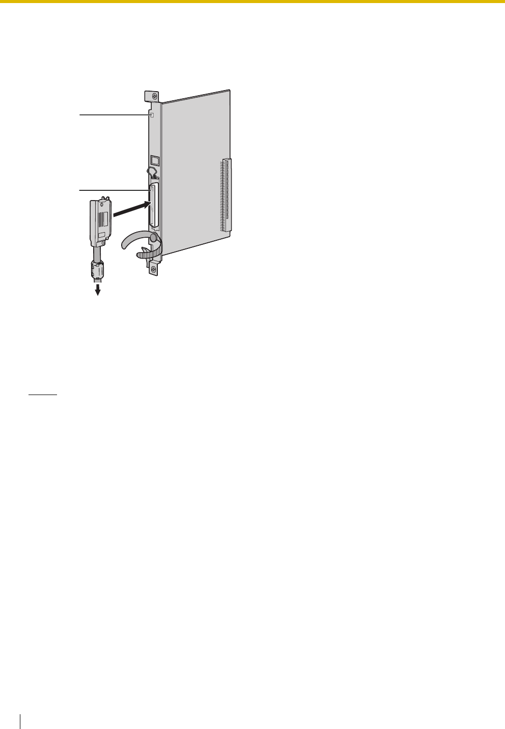
2.5 Information about the Extension Cards
116 Installation Manual
2.5.5 SLC8 Card (KX-TDA0173)
Function
8-port extension card for SLTs with 2 power failure transfer (PFT) ports.
Accessories and User-supplied Items
Accessories (included): Screws × 2, Ferrite core × 1
User-supplied (not included): Amphenol connector
Notes
• Attach the included ferrite core to the cable. Refer to "2.2.9 Attaching a Ferrite Core".
• To connect the Amphenol connector, refer to "2.2.10 Fastening Amphenol Connector".
• For details about power failure transfer, refer to "2.12.1 Power Failure Connections".
LED
Amphenol
To extensions
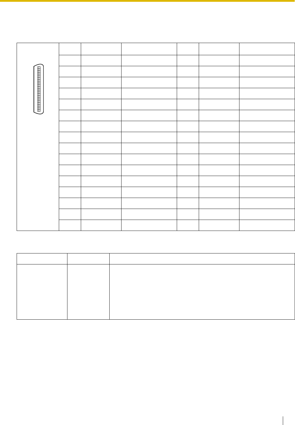
2.5 Information about the Extension Cards
Installation Manual 117
Pin Assignments
Amphenol Connector
LED Indications
No. Signal Name Function No. Signal Name Function
1 RA Ring port 1 26 TA Tip port 1
2-3 Reserved – 27-28 Reserved –
4 RB Ring port 2 29 TB Tip port 2
5-6 Reserved – 30-31 Reserved –
7 RC Ring port 3 32 TC Tip port 3
8-9 Reserved – 33-34 Reserved –
10 RD Ring port 4 35 TD Tip port 4
11-12 Reserved – 36-37 Reserved –
13 RE Ring port 5 38 TE Tip port 5
14-15 Reserved – 39-40 Reserved –
16 RF Ring port 6 41 TF Tip port 6
17-18 Reserved – 43-44 Reserved –
19 RG Ring port 7 44 TG Tip port 7
20-21 Reserved – 45-46 Reserved –
22 RH Ring port 8 47 TH Tip port 8
23-25 Reserved – 48-50 Reserved –
Indication Colour Description
CARD STATUS Green/Red Card status indication
• OFF: Power Off
• Green ON: Normal (all ports are idle)
• Green Flashing (60 times per minute): Normal (a port is in use)
• Red ON: Fault (includes reset)
• Red Flashing (60 times per minute): Out of Service
50 25
26 1
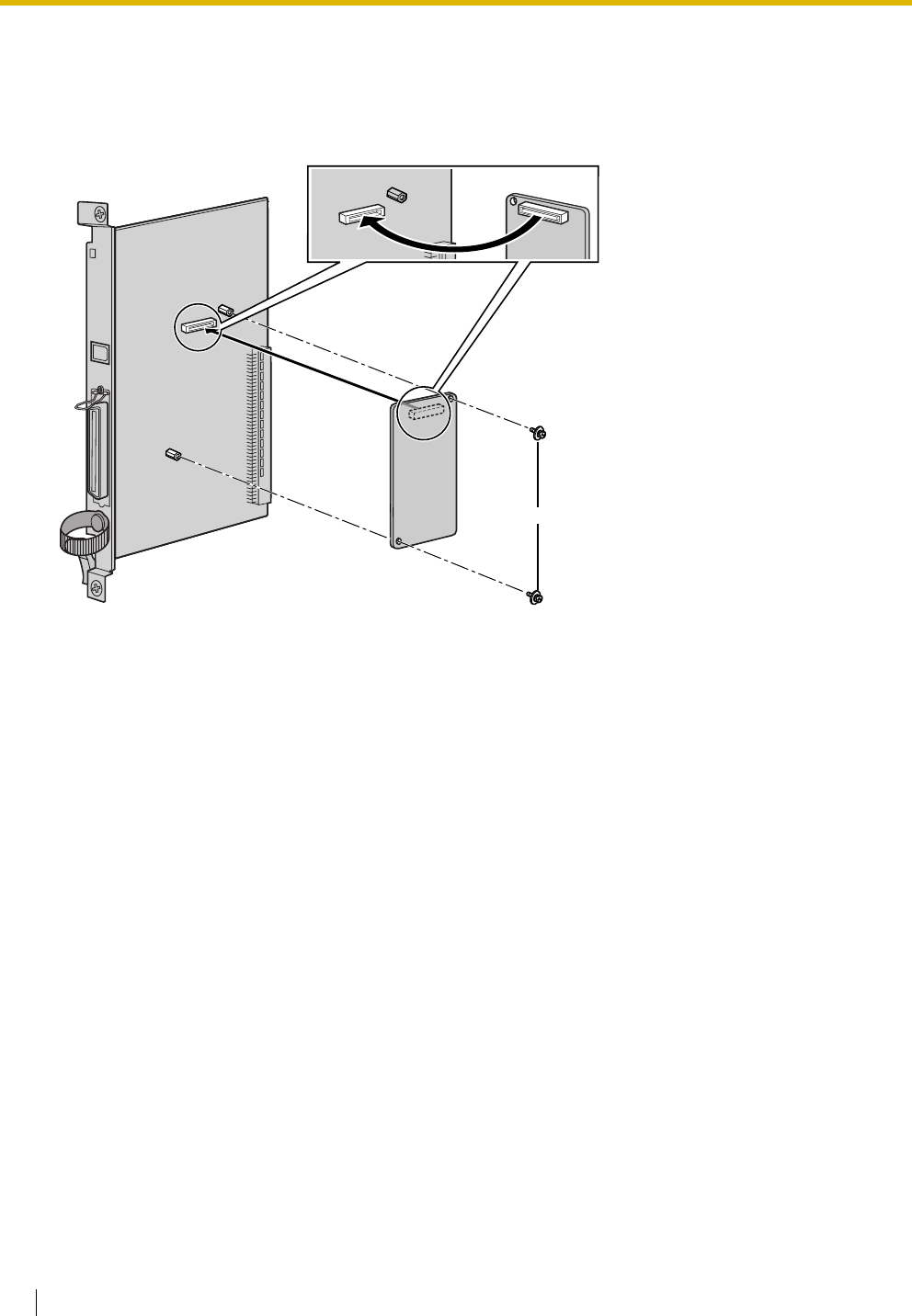
2.5 Information about the Extension Cards
118 Installation Manual
2.5.6 EXT-CID Card (KX-TDA0168)
Function
Sends Caller ID signals to extension ports. To be mounted on the SLC8 card only.
Accessories and User-supplied Items
Accessories (included): Screws × 2
User-supplied (not included): none
EXT-CID Card
Screw
SLC8 Card inside
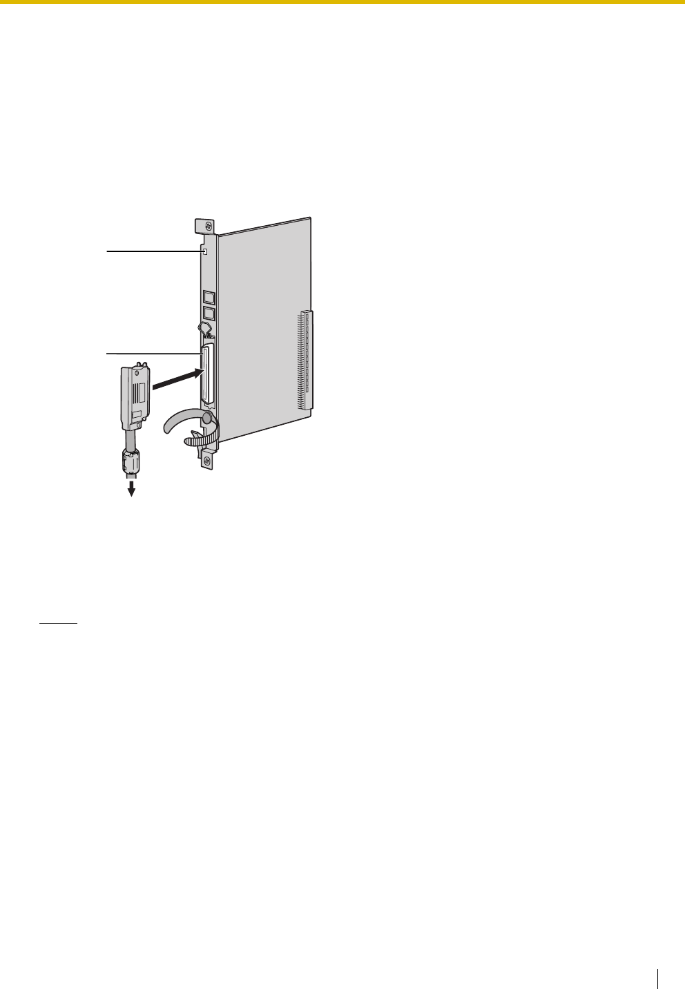
2.5 Information about the Extension Cards
Installation Manual 119
2.5.7 SLC16 Card (KX-TDA0174) and MSLC16 Card (KX-
TDA0175)
Function
Accessories and User-supplied Items
Accessories (included): Screws × 2, Ferrite core × 1
User-supplied (not included): Amphenol connector
Notes
• Panasonic SLT with Message Waiting Lamp (e.g., KX-T7310) is recommended for connection to
the MSLC16 card.
• Attach the included ferrite core to the cable. Refer to "2.2.9 Attaching a Ferrite Core".
• To connect the Amphenol connector, refer to "2.2.10 Fastening Amphenol Connector".
• For details about power failure transfer, refer to "2.12.1 Power Failure Connections".
SLC16: 16-port extension card for SLTs with 4 power failure transfer (PFT) ports.
MSLC16: 16-port extension card for SLTs with Message Waiting Lamp control and 4 power failure
transfer (PFT) ports. Maximum power output of 160 V/90 V for Message Waiting Lamp
control.
LED
Amphenol
To extensions
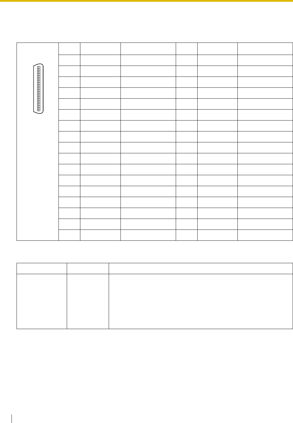
2.5 Information about the Extension Cards
120 Installation Manual
Pin Assignments
Amphenol Connector
LED Indications
No. Signal Name Function No. Signal Name Function
1 RA Ring port 1 26 TA Tip port 1
2 RB Ring port 2 27 TB Tip port 2
3 RC Ring port 3 28 TC Tip port 3
4 RD Ring port 4 29 TD Tip port 4
5 RE Ring port 5 30 TE Tip port 5
6 RF Ring port 6 31 TF Tip port 6
7 RG Ring port 7 32 TG Tip port 7
8 RH Ring port 8 33 TH Tip port 8
9 RI Ring port 9 34 TI Tip port 9
10 RJ Ring port 10 35 TJ Tip port 10
11 RK Ring port 11 36 TK Tip port 11
12 RL Ring port 12 37 TL Tip port 12
13 RM Ring port 13 38 TM Tip port 13
14 RN Ring port 14 39 TN Tip port 14
15 RO Ring port 15 40 TO Tip port 15
16 RP Ring port 16 41 TP Tip port 16
17-25 Reserved – 42-50 Reserved –
Indication Colour Description
CARD STATUS Green/Red Card status indication
• OFF: Power Off
• Green ON: Normal (all ports are idle)
• Green Flashing (60 times per minute): Normal (a port is in use)
• Red ON: Fault (includes reset)
• Red Flashing (60 times per minute): Out of Service
50 25
26 1
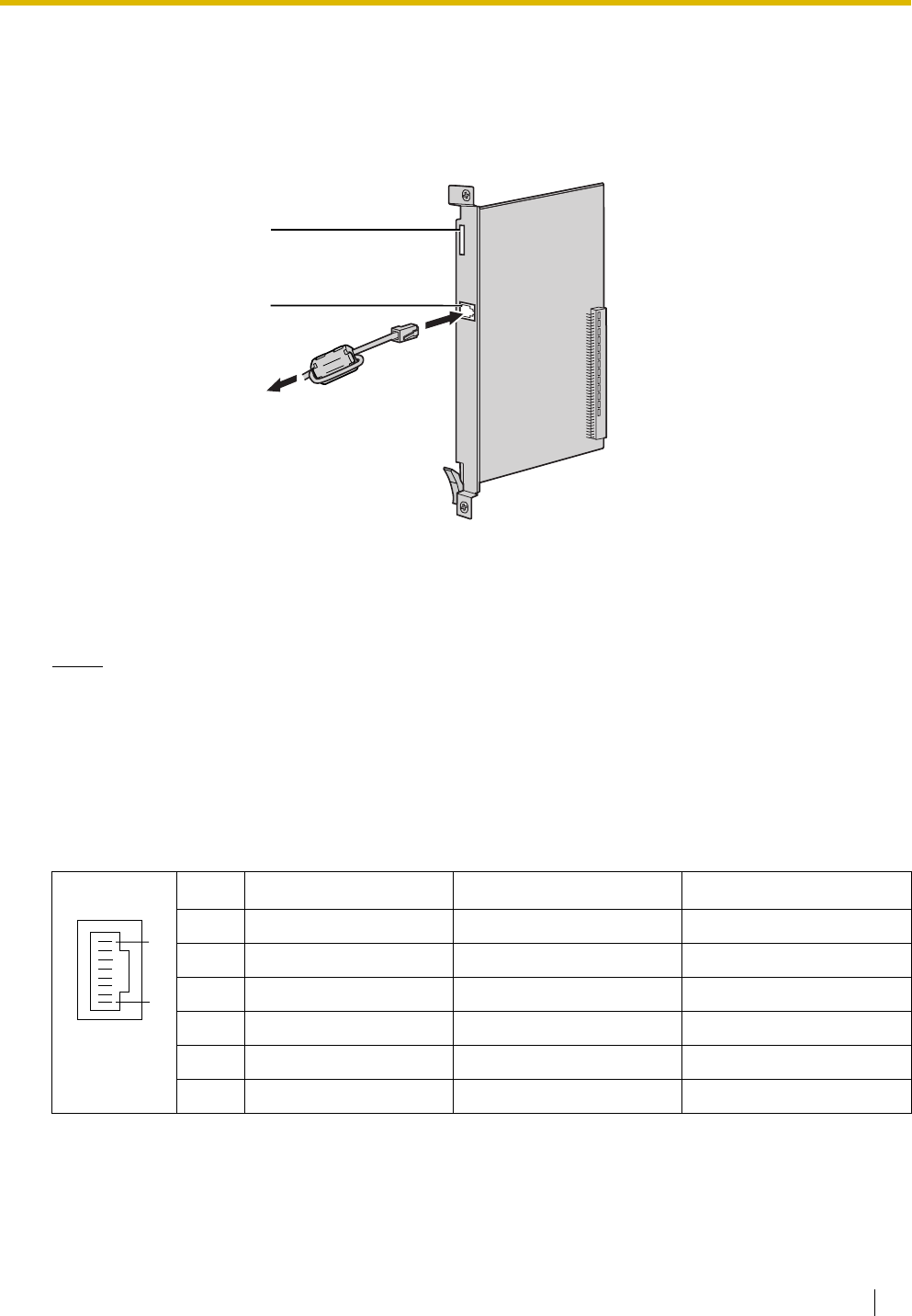
2.5 Information about the Extension Cards
Installation Manual 121
2.5.8 IP-EXT16 Card (KX-TDA0470)
Function
16-channel VoIP extension card. Compliant with Panasonic proprietary protocol, and ITU-T G.729a and
G.711 CODEC methods.
Accessories and User-supplied Items
Accessories (included): Ferrite core × 1
User-supplied (not included): RJ45 connector
Notes
• The maximum length of the cable to be connected to this optional service card is 100 m.
• When connecting the RJ45 connector, attach the included ferrite core. Refer to "2.2.9 Attaching a
Ferrite Core".
Pin Assignments
RJ45 Connector (10BASE-T/100BASE-TX)
No. Signal Name Input (I)/Output (O) Function
1 TPO+ O Transmit data+
2 TPO- O Transmit data-
3TPI+ I Receive data+
4-5 Reserved – –
6TPI- I Receive data-
7-8 Reserved – –
LEDs
RJ45
(10BASE-T/100BASE-TX
Full Duplex)
To private IP network
8
1

2.5 Information about the Extension Cards
122 Installation Manual
LED Indications
Indication Colour Description
CARD STATUS Green/Red Card status indication
• OFF: Power Off
• Green ON: Normal (all ports are idle)
• Green Flashing (60 times per minute): Normal (a port is in use)
• Red ON: Fault (includes reset)
• Red Flashing (60 times per minute): Out of Service
ONLINE Green On-line status indication
• ON: At least one port is in use (an IP-PT is connected)
• OFF: No ports are in use (no IP-PTs are connected)
Note
If the LINK indicator is OFF, the ONLINE indicator will also be
OFF.
ALARM Red Alarm indication
• OFF: Normal
•ON: Alarm
VoIP BUSY Green Panasonic proprietary VoIP protocol process indication
• OFF: VoIP process inactive
• ON: VoIP process active
LINK Green Link status indication
• OFF: Connection error
• ON: Normal connection
DATA Green Data transmission indication
• OFF: No data transmitted
• ON: Data transmitting
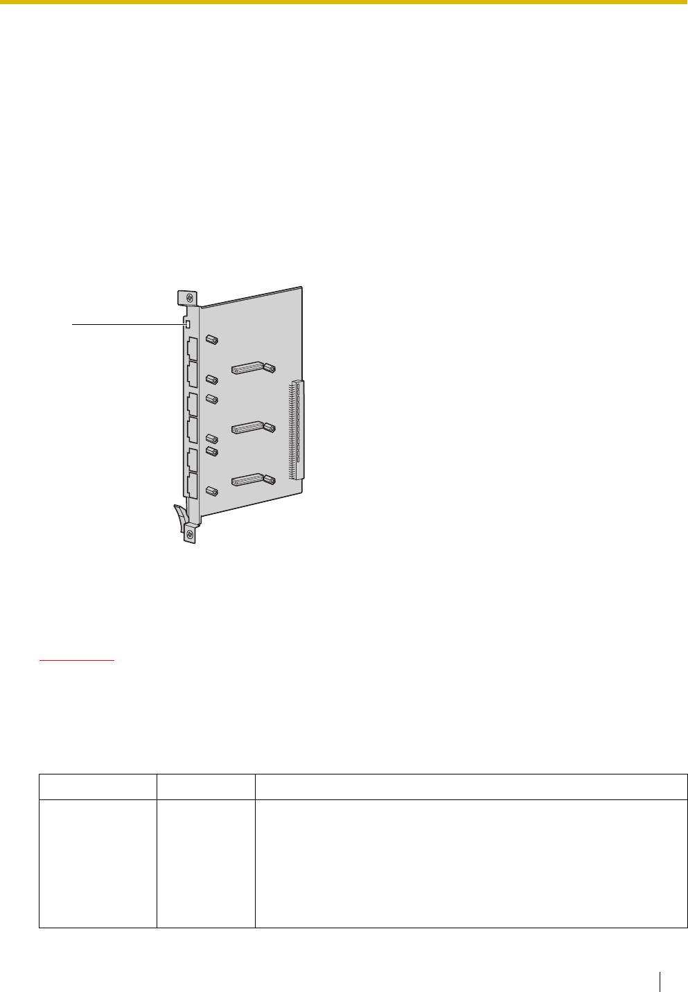
2.6 Information about the Other Cards
Installation Manual 123
2.6 Information about the Other Cards
2.6.1 OPB3 Card (KX-TDA0190)
Function
Optional 3-slot base card for mounting a maximum of 3 option cards from the following:
•DPH4 card
•DPH2 card
•EIO4 card
• ECHO16 card
•MSG4 card
Accessories and User-supplied Items
Accessories (included): none
User-supplied (not included): none
CAUTION
A LITHIUM BATTERY IS USED IN OPB3 CARD. THERE IS A RISK OF EXPLOSION IF THE BATTERY
IS REPLACED WITH THE INCORRECT TYPE. DISPOSE OF USED BATTERIES ACCORDING TO
THE MANUFACTURER'S INSTRUCTIONS.
LED Indications
Indication Colour Description
CARD STATUS Green/Red Card status indication
• OFF: Power Off
• Green ON: Normal (all ports are idle)
• Green Flashing (60 times per minute): Normal (a port is in use)
• Red ON: Fault (includes reset)
• Red Flashing (60 times per minute): Out of Service
LED
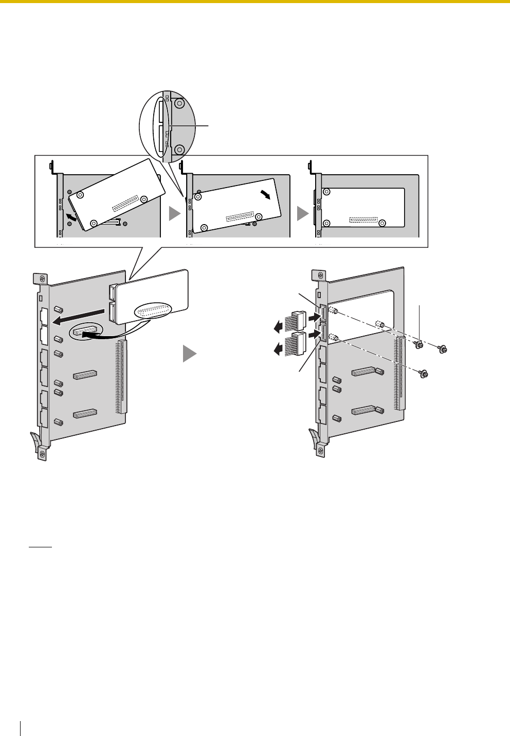
2.6 Information about the Other Cards
124 Installation Manual
2.6.2 DPH4 Card (KX-TDA0161)
Function
4-port doorphone card for 4 doorphones and 4 door openers. To be mounted on the OPB3 card.
Accessories and User-supplied Items
Accessories (included): Screws × 3, 10-pin terminal block × 1, 8-pin terminal block × 1
User-supplied (not included): Copper wire
Note
For details about connection to doorphones and door openers, refer to "2.10.1 Connection of
Doorphones, Door Openers, External Sensors, and External Relays".
Screw
DPH4 Card
OPB3 Card
Fully insert the connectors through
the panel openings.
To door openers
To doorphones
10-pin
8-pin

2.6 Information about the Other Cards
Installation Manual 125
Pin Assignments
8-pin Terminal Block
10-pin Terminal Block
No. Signal Name Function
1 DP4 Doorphone 4 transmit
2 com4 Doorphone 4 receive
3 DP3 Doorphone 3 transmit
4 com3 Doorphone 3 receive
5 DP2 Doorphone 2 transmit
6 com2 Doorphone 2 receive
7 DP1 Doorphone 1 transmit
8 com1 Doorphone 1 receive
No. Signal Name Function
1-2 Reserved –
3 OP4b Door opener 4
4 OP4a Door opener 4 com
5 OP3b Door opener 3
6 OP3a Door opener 3 com
7 OP2b Door opener 2
8 OP2a Door opener 2 com
9 OP1b Door opener 1
10 OP1a Door opener 1 com
8
1
10
1
2.6 Information about the Other Cards
126 Installation Manual
2.6.3 DPH2 Card (KX-TDA0162)
Function
2-port doorphone card for 2 German-type doorphones and 2 door openers. To be mounted on the OPB3
card.
Accessories and User-supplied Items
Accessories (included): Screws × 3, 10-pin terminal block × 1, 8-pin terminal block × 1
User-supplied (not included): Copper wire
Note
For details about connection to doorphones and door openers, refer to "2.10.1 Connection of
Doorphones, Door Openers, External Sensors, and External Relays".
Screw
DPH2 Card
OPB3 Card
Fully insert the connectors through
the panel openings.
To doorphones/
door openers
10-pin
8-pin
2.6 Information about the Other Cards
Installation Manual 127
Pin Assignments
8-pin Terminal Block
10-pin Terminal Block
No. Signal Name Function
1 Path_2b Doorphone 2 transmit
2 Path_2a Doorphone 2 receive
3 Call_2b Doorphone 2 call button
4 Call_2a Doorphone 2 call button com
5 Path_1b Doorphone 1 transmit
6 Path_1a Doorphone 1 receive
7 Call_1b Doorphone 1 call button
8 Call_1a Doorphone 1 call button com
No. Signal Name Function
1-2 Reserved –
3 OP2b Door opener 2
4 OP2a Door opener 2 com
5 OP1b Door opener 1
6 OP1a Door opener 1 com
7 DC2b Doorphone control 2
8 DC2a Doorphone control 2 com
9 DC1b Doorphone control 1
10 DC1a Doorphone control 1 com
8
1
10
1
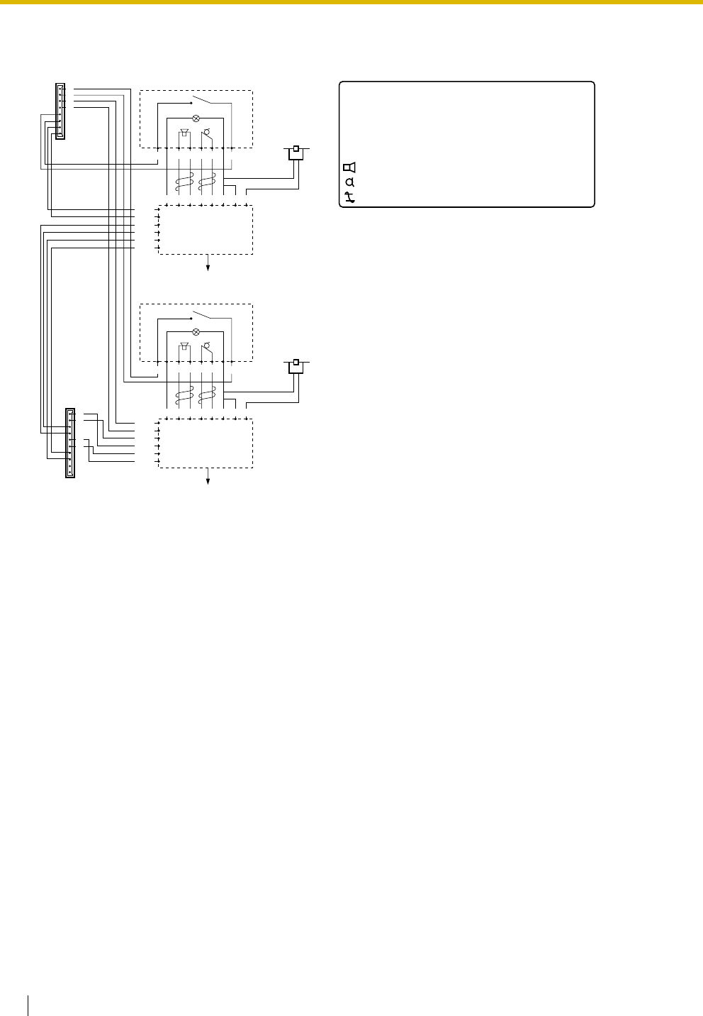
2.6 Information about the Other Cards
128 Installation Manual
Connection Diagram for German-type Doorphones and Door Openers
German-type Doorphone 2
Doorphone 2
Adaptor
220 V~
BL Door
Opener 2
RT
LOUB
Path_2a
Path_2b
DC2b
DC2a
OP2b
OP2a
10
9
8
7
6
5
4
3
2
1
Path_1a
Path_1b
DC1b
DC1a
OP1b
OP1a
8
7
6
5
4
3
2
1
LOUB
~12 V~8 V TO~0 V
BL: Light
RT: Call Button
OP: Door Opener Connection Terminal
DC: Doorphone Current Supply Control Terminal
Path: Doorphone Call Path
: Speaker
: Microphone
: Shield
Call_2b
Call_1a
Call_2a
Call_1b
Doorphone 1
Adaptor
220 V~
BL Door
Opener 1
RT
LOUB
LOUB
~12 V~8 V TO~0 V
German-type Doorphone 1
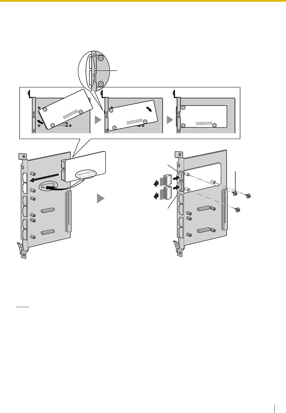
2.6 Information about the Other Cards
Installation Manual 129
2.6.4 EIO4 Card (KX-TDA0164)
Function
4-port external input/output card. To be mounted on the OPB3 card.
Accessories and User-supplied Items
Accessories (included): Screws × 3, 10-pin terminal block × 1, 8-pin terminal block × 1
User-supplied (not included): Copper wire
Note
For details about connection to external sensors and external relays, refer to "2.10.1 Connection of
Doorphones, Door Openers, External Sensors, and External Relays".
Screw
EIO4 Card
OPB3 Card
Fully insert the connectors through
the panel openings.
To external relays
To external sensors
10-pin
8-pin

2.6 Information about the Other Cards
130 Installation Manual
Pin Assignments
8-pin Terminal Block
10-pin Terminal Block
No. Signal Name Function
1C4b Control 4
2 C4a Control 4 com
3C3b Control 3
4 C3a Control 3 com
5C2b Control 2
6 C2a Control 2 com
7C1b Control 1
8 C1a Control 1 com
No. Signal Name Function
1-2 Reserved –
3 OP4b Opener 4
4 OP4a Opener 4 com
5 OP3b Opener 3
6 OP3a Opener 3 com
7 OP2b Opener 2
8 OP2a Opener 2 com
9 OP1b Opener 1
10 OP1a Opener 1 com
8
1
10
1
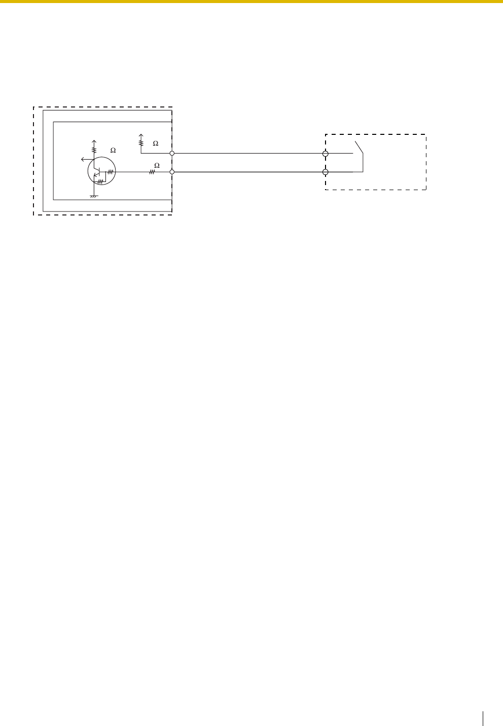
2.6 Information about the Other Cards
Installation Manual 131
External Sensor
Power to the external sensor is provided from the EIO4 card and must be grounded through the EIO4 card
as indicated in the diagram below. A pair of "sensor" and "common" lines are connected to the EIO4 card
for each external sensor. The Hybrid IP-PBX detects input from the sensor when the signal is under 100 Ω.
Connection Diagram
External Relay
Current Limit: 24 V DC/30 V AC, 1 A maximum
External Sensor
sensor
common
I/O
EIO4
OPB3
Hybrid IP-PBX
+5V +5V
10K 33
33
4.7K
4.7K
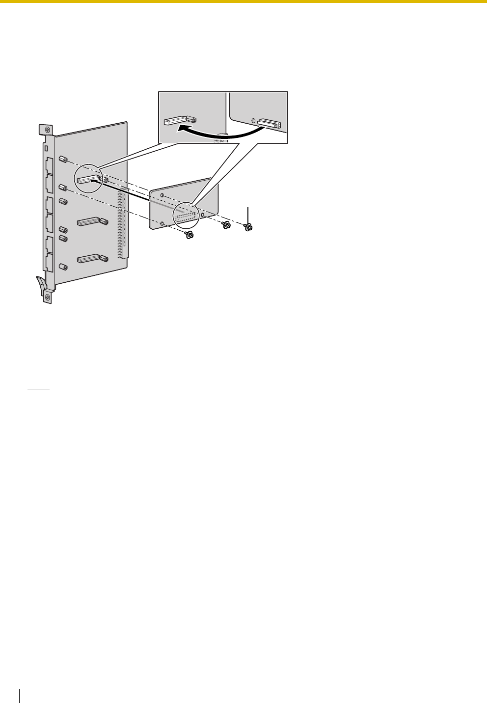
2.6 Information about the Other Cards
132 Installation Manual
2.6.5 ECHO16 Card (KX-TDA0166)
Function
16-channel card for echo cancellation during conferences. To be mounted on the OPB3 card.
Accessories and User-supplied Items
Accessories (included): Screws × 3
User-supplied (not included): none
Note
To establish a conference call involving 6 to 8 parties, install an ECHO16 card and enable echo
cancellation for conferences using the KX-TDA Maintenance Console. For details, refer to the on-line
help of the KX-TDA Maintenance Console.
Screw
inside
ECHO16 Card
OPB3 Card
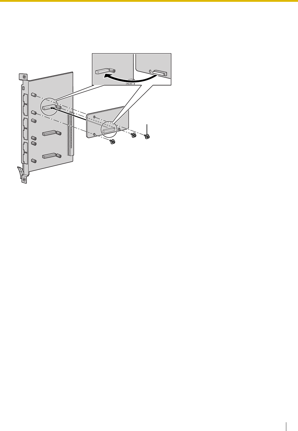
2.6 Information about the Other Cards
Installation Manual 133
2.6.6 MSG4 Card (KX-TDA0191)
Function
4-channel message card. To be mounted on the OPB3 card.
Accessories and User-supplied Items
Accessories (included): Screws × 3
User-supplied (not included): none
Screw
MSG4 Card
OPB3 Card
inside
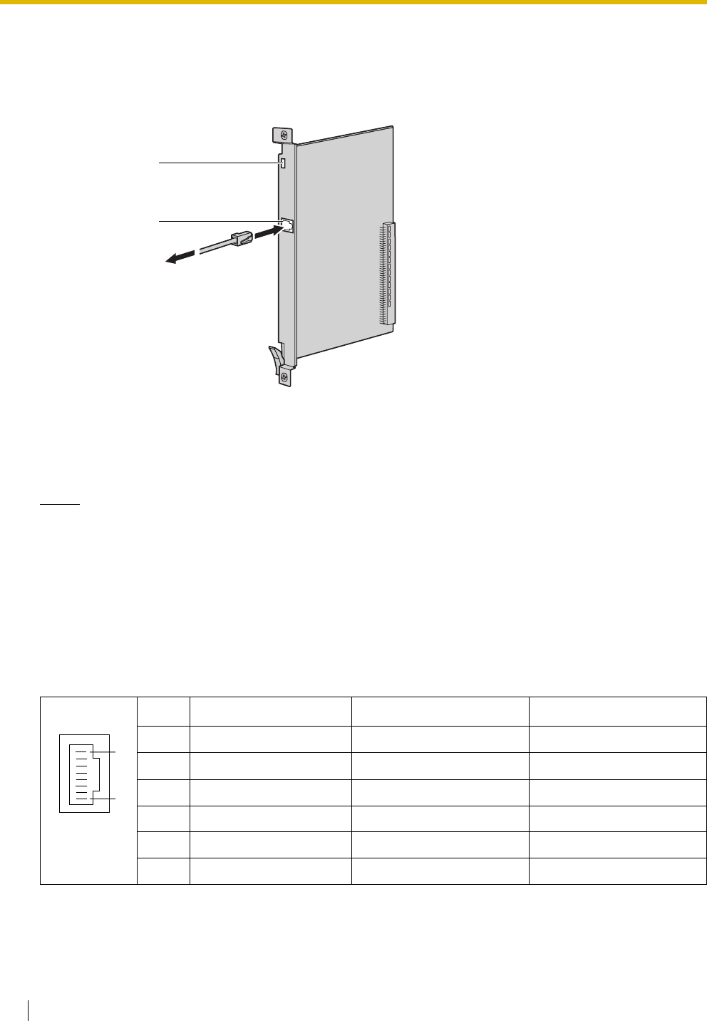
2.6 Information about the Other Cards
134 Installation Manual
2.6.7 CTI-LINK Card (KX-TDA0410)
Function
Ethernet card for CTI communication via 10BASE-T port. CSTA Phase 3 protocol compatible.
Accessories and User-supplied Items
Accessories (included): none
User-supplied (not included): RJ45 connector
Notes
• The maximum length of the cable to be connected to this optional service card is 100 m.
• This optional service card can be connected to PCs on a LAN via a CTI server to provide third party
call control CTI.
The operating system of the PC or CTI server required for third party call control depends on your
CTI application software. For details, refer to the manual for your CTI application software.
Pin Assignments
RJ45 Connector (10BASE-T)
No. Signal Name Input (I)/Output (O) Function
1 TPO+ O Transmit data+
2 TPO- O Transmit data-
3TPI+ I Receive data+
4-5 Reserved – –
6TPI- I Receive data-
7-8 Reserved – –
LEDs
RJ45 (10BASE-T)
To LAN/
CTI Server
8
1

2.6 Information about the Other Cards
Installation Manual 135
LED Indications
Indication Colour Description
CARD STATUS Green/Red Card status indication
• OFF: Power Off
• Green ON: Normal
• Red ON: Fault (includes reset)
• Red Flashing (60 times per minute): Out of Service
LINK STATUS Green Link status indication
• Flashing: In communication
• ON: Linked normally
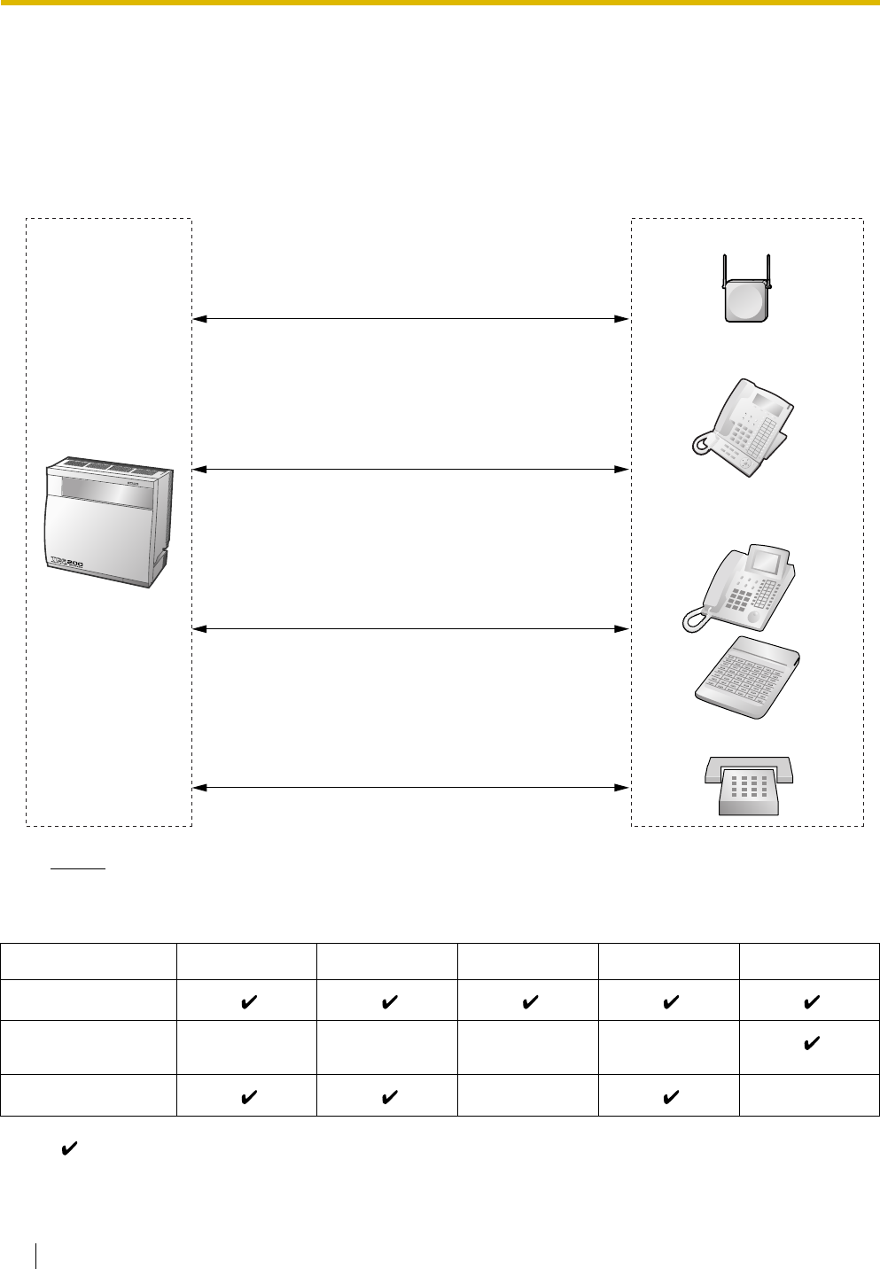
2.7 Connection of Extensions
136 Installation Manual
2.7 Connection of Extensions
2.7.1 Maximum Cabling Distances of the Extension Wiring
(Twisted Cable)
Notice
The maximum cabling distance may vary depending on the conditions.
" " indicates that the extension card supports the terminal.
PT-interface CS DPT APT DSS Console SLT
DHLC8 Card
MSLC16, SLC16,
SLC8 Cards
DLC16, DLC8 Cards
Cable Maximum Distance
ø 0.4 mm: 500 m
ø 0.5 mm: 720 m
ø 0.6 mm: 830 m
CAT 5: 720 m
Cable Maximum Distance
ø 0.4 mm: 140 m
ø 0.5 mm: 229 m
ø 0.6 mm: 360 m
CAT 5: 229 m
Cable Maximum Distance
ø 0.4 mm: 698 m
ø 0.5 mm: 1128 m
ø 0.6 mm: 1798 m
CAT 5: 1128 m
Other PT (DPT/APT)
and DSS Console
SLT
KX-T7600 Series DPT
PT-interface CS
Cable Maximum Distance
ø 0.4 mm: 222 m
ø 0.5 mm: 347 m
ø 0.6 mm: 500 m
CAT 5: 347 m
2.7 Connection of Extensions
Installation Manual 137
2.7.2 Parallel Connection of the Extensions
Any SLT can be connected in parallel with an APT or a DPT as follows.
Note
In addition to an SLT, an answering machine, a fax machine or a modem (PC) can be connected in
parallel with an APT or a DPT.
With APT
For parallel connection, eXtra Device Port (XDP) mode must be disabled for that port through system
programming. Refer to "1.10.9 Parallelled Telephone" and "2.1.1 Extension Port Configuration" in the
Feature Guide for further information.
With DPT
Parallel mode or eXtra Device Port (XDP) mode can be selected through system programming.
If XDP mode is enabled through system programming, parallel connection is not possible. Refer to "1.10.9
Parallelled Telephone" and "2.1.1 Extension Port Configuration" in the Feature Guide for further information.
Using a Modular T-Adaptor
To DHLC8 card
4-conductor wiring cord
Connect pins "T", "R", "D1",
and "D2".
2-conductor wiring cord
Connect pins "T" and "R".
SLTAPT
Modular
T-Adaptor
To DHLC8 card
SLTDPT
Modular
T-Adaptor
4-conductor wiring cord
Connect pins "D1" and
"D2".
2-conductor wiring cord
Connect pins "T" and "R".
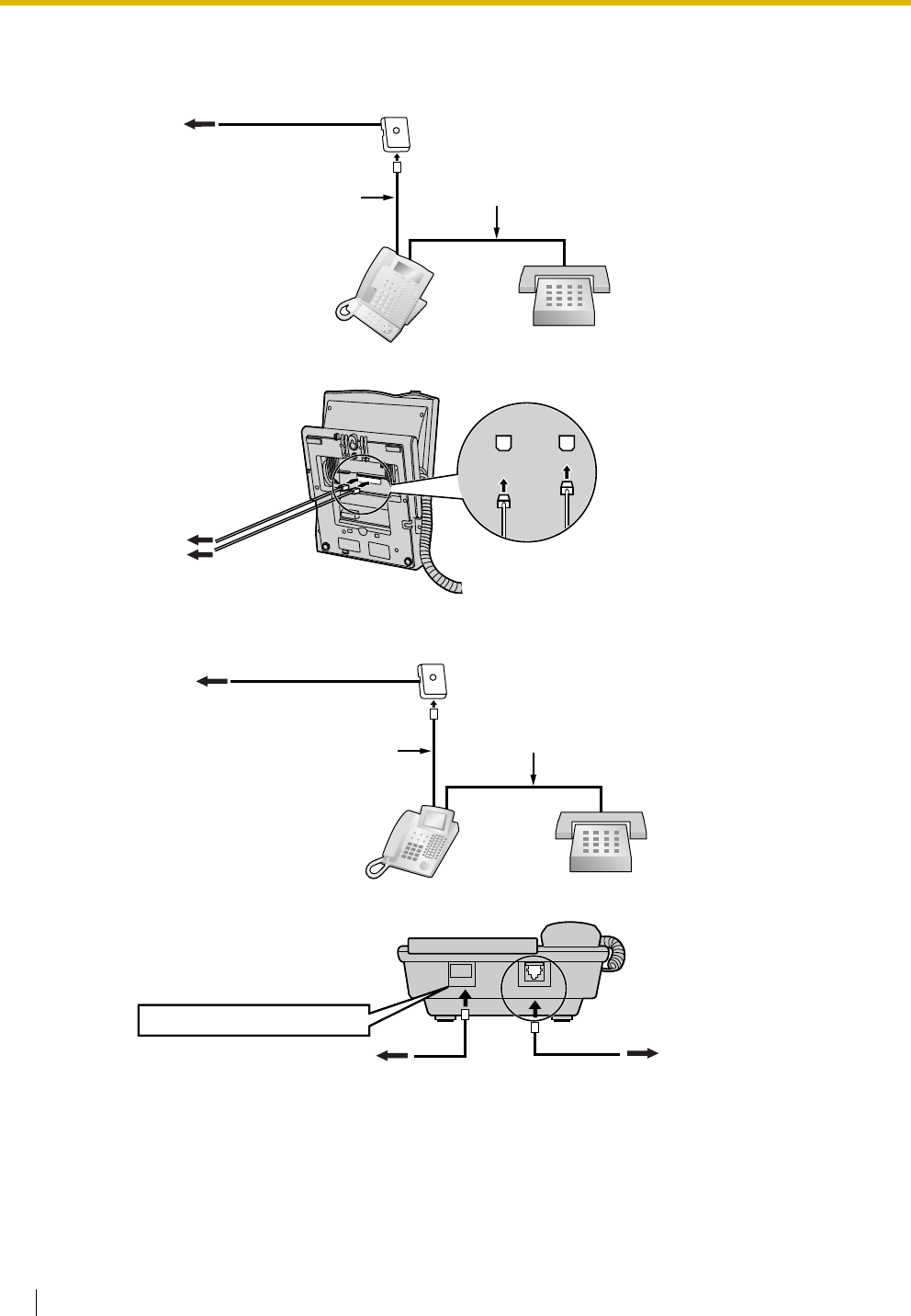
2.7 Connection of Extensions
138 Installation Manual
Using an EXtra Device Port
With KX-T7600 Series DPT (except KX-T7665)
With Other DPT (except KX-T7560 and KX-T7565)
To DHLC8 card
DPT SLT
To DHLC8 card
To S LT
2-conductor wiring cord
Connect pins "T" and "R".
4-conductor wiring cord
Connect pins "T", "R",
"D1" and "D2".
TO MAIN UNIT
/ PABX
TO TEL
To DHLC8 card
DPT SLT
To DHLC8 card To S LT
2-conductor wiring cord
Connect pins "T" and "R".
4-conductor wiring cord
Connect pins "T", "R",
"D1" and "D2".
TO TEL
TO EMSS or TO MAIN UNIT
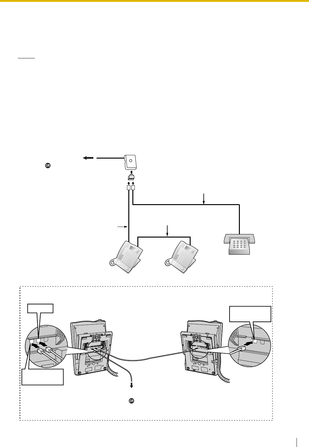
2.7 Connection of Extensions
Installation Manual 139
2.7.3 Digital EXtra Device Port (Digital XDP) Connection
A DPT can be connected to another DPT on the Digital XDP connection. In addition, if the DPT is connected
to a DHLC8 card, it can also have an SLT connected in Parallel mode or XDP mode.
Notes
• Both DPTs must be KX-T7600 series DPTs (except KX-T7640). Note that the KX-T7667 can only
be connected as a slave DPT.
• Parallel mode or XDP mode can be selected through system programming.
• If XDP mode is enabled through system programming, parallel connection is not possible. Refer to
"1.10.9 Parallelled Telephone" and "2.1.1 Extension Port Configuration" in the Feature Guide for
further information.
With KX-T7600 Series DPT (except KX-T7600E Series)
Using a Modular T-Adaptor
To DLC8/DLC16 card
To DHLC8 card
(for connection of SLT)
4-conductor wiring cord
Connect pins "D1" and "D2".
Slave DPT
SLT
Master DPT
Modular
T-Adaptor
4-conductor wiring cord
Connect pins "D1" and
"D2".
2-conductor wiring cord
Connect pins "T" and "R".
Slave DPTMaster DPT
TO MAIN UNIT
/ PABX
TO TEL
TO MAIN UNIT
/ PABX
Cable Maximum Distance
ø 0.4 mm: 30 m
ø 0.5 mm: 50 m
ø 0.6 mm: 60 m
CAT 5: 50 m
Back View of DPTs
To DLC8/DLC16 card
To DHLC8 card
(for connection of SLT)
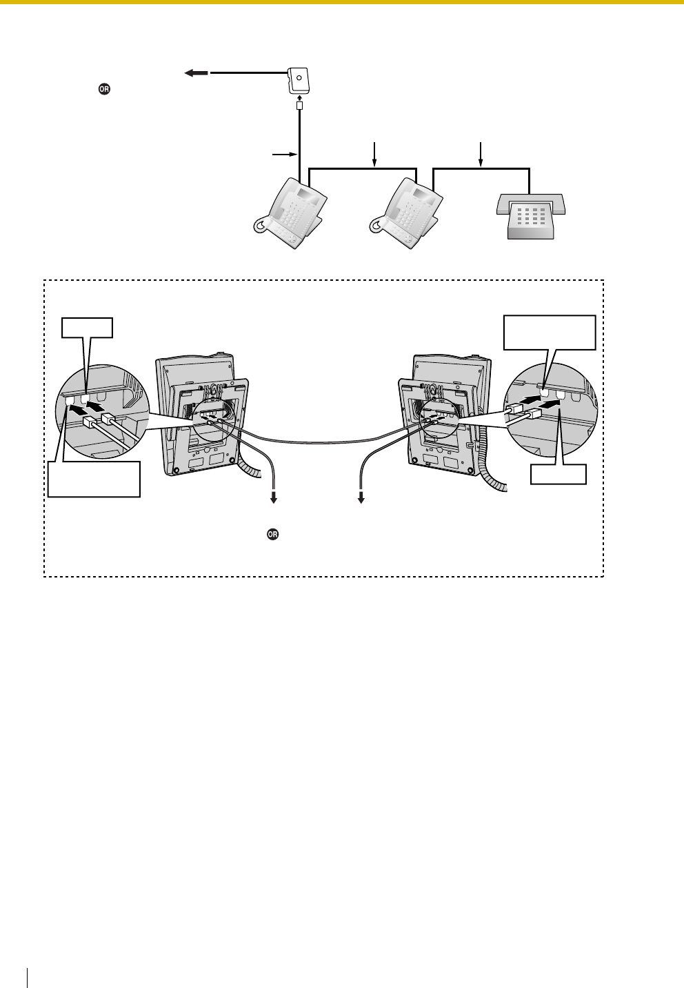
2.7 Connection of Extensions
140 Installation Manual
Using an EXtra Device Port
SLTMaster DPT Slave DPT
4-conductor wiring cord
Connect pins "T", "R",
"D1" and "D2".
2-conductor wiring cord
Connect pins "T" and "R".
4-conductor wiring cord
Connect pins "T", "R",
"D1" and "D2".
Slave DPTMaster DPT
To SLT
TO MAIN UNIT
/ PABX
TO TEL
TO TEL
TO MAIN UNIT
/ PABX
Cable Maximum Distance
ø 0.4 mm: 30 m
ø 0.5 mm: 50 m
ø 0.6 mm: 60 m
CAT 5: 50 m
Back View of DPTs
To DLC8/DLC16 card
To DHLC8 card
(for connection of SLT)
To DLC8/DLC16 card
To DHLC8 card
(for connection of SLT)
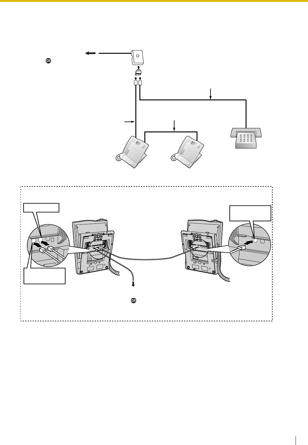
2.7 Connection of Extensions
Installation Manual 141
With KX-T7600E Series DPT
Using a Modular T-Adaptor
4-conductor wiring cord
Connect pins "D1" and "D2".
Slave DPT
SLT
Master DPT
Modular
T-Adaptor
4-conductor wiring cord
Connect pins "D1" and "D2".
2-conductor wiring cord
Connect pins "T" and "R".
Slave DPTMaster DPT
TO MAIN UNIT
/ PABX
TO DIGITAL
TO MAIN UNIT
/ PABX
Cable Maximum Distance
ø 0.4 mm: 30 m
ø 0.5 mm: 50 m
ø 0.6 mm: 60 m
CAT 5: 50 m
Back View of DPTs
To DLC8/DLC16 card
To DHLC8 card
(for connection of SLT)
To DLC8/DLC16 card
To DHLC8 card
(for connection of SLT)
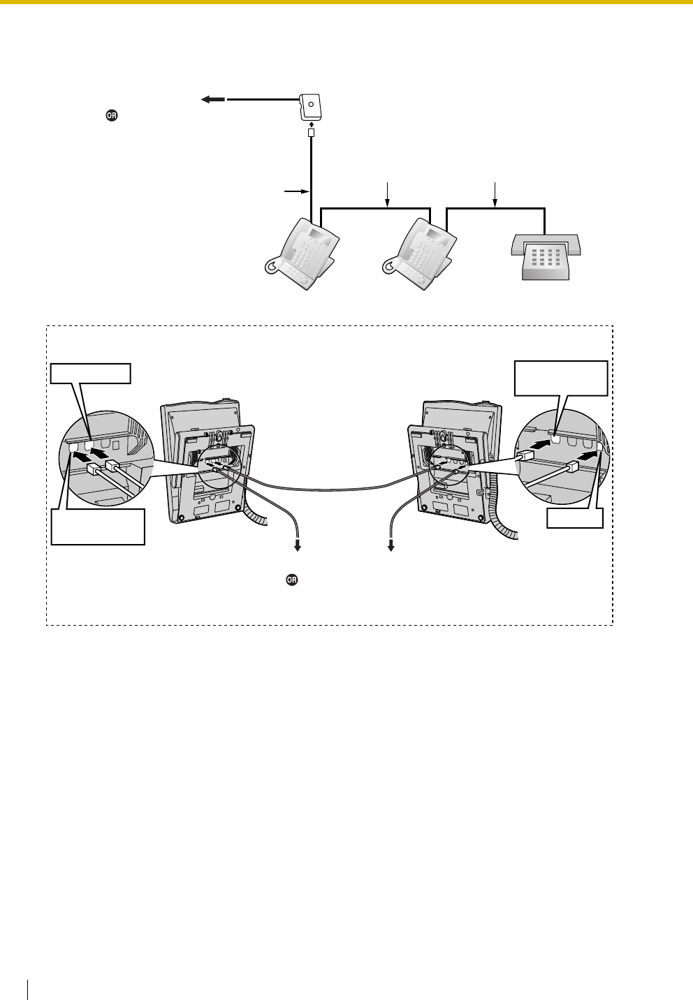
2.7 Connection of Extensions
142 Installation Manual
Using an EXtra Device Port
Connecting to a Slave DPT
SLTMaster DPT Slave DPT
4-conductor wiring cord
Connect pins "T", "R",
"D1" and "D2".
2-conductor wiring cord
Connect pins "T" and "R".
4-conductor wiring cord
Connect pins "T", "R",
"D1" and "D2".
Slave DPTMaster DPT
To SLT
TO MAIN UNIT
/ PABX
TO TEL
TO DIGITAL
TO MAIN UNIT
/ PABX
Cable Maximum Distance
ø 0.4 mm: 30 m
ø 0.5 mm: 50 m
ø 0.6 mm: 60 m
CAT 5: 50 m
Back View of DPTs
To DLC8/DLC16 card
To DHLC8 card
(for connection of SLT)
To DLC8/DLC16 card
To DHLC8 card
(for connection of SLT)
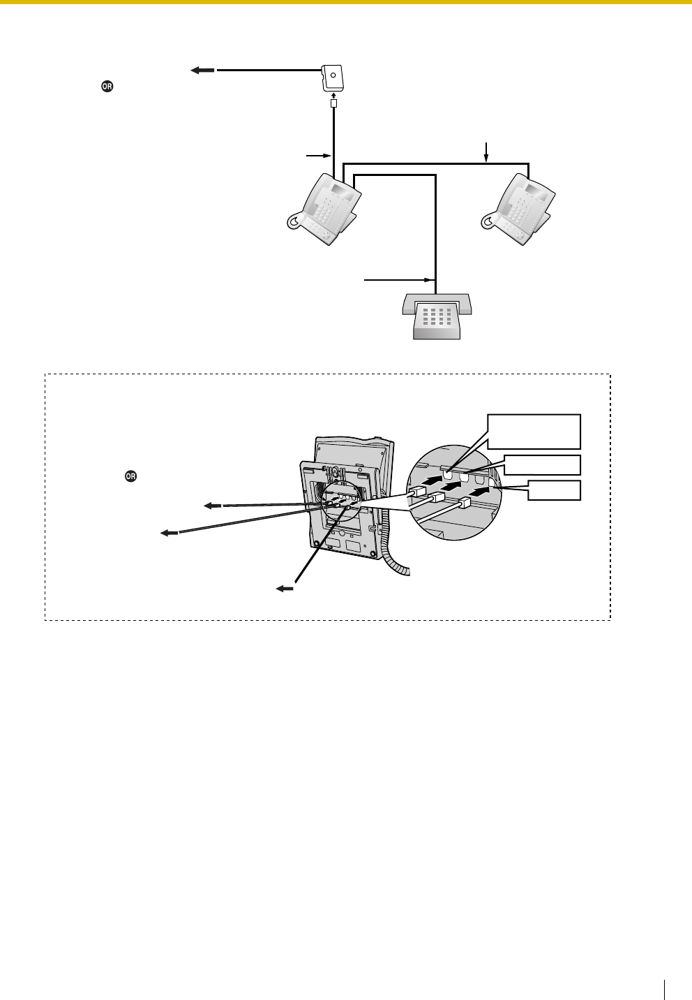
2.7 Connection of Extensions
Installation Manual 143
Connecting to a Master DPT
SLT
To slave DPT
To S LT
Master DPT Slave DPT
4-conductor wiring cord
Connect pins "D1" and "D2".
2-conductor wiring cord
Connect pins "T" and "R".
4-conductor wiring cord
Connect pins "T", "R",
"D1" and "D2".
TO DIGITAL
TO MAIN UNIT
/ PABX
TO TEL
Back View of DPTs
Cable Maximum Distance
ø 0.4 mm: 30 m
ø 0.5 mm: 50 m
ø 0.6 mm: 60 m
CAT 5: 50 m
To DLC8/DLC16 card
To DHLC8 card
(for connection of SLT)
To DLC8/DLC16 card
To DHLC8 card
(for connection of SLT)
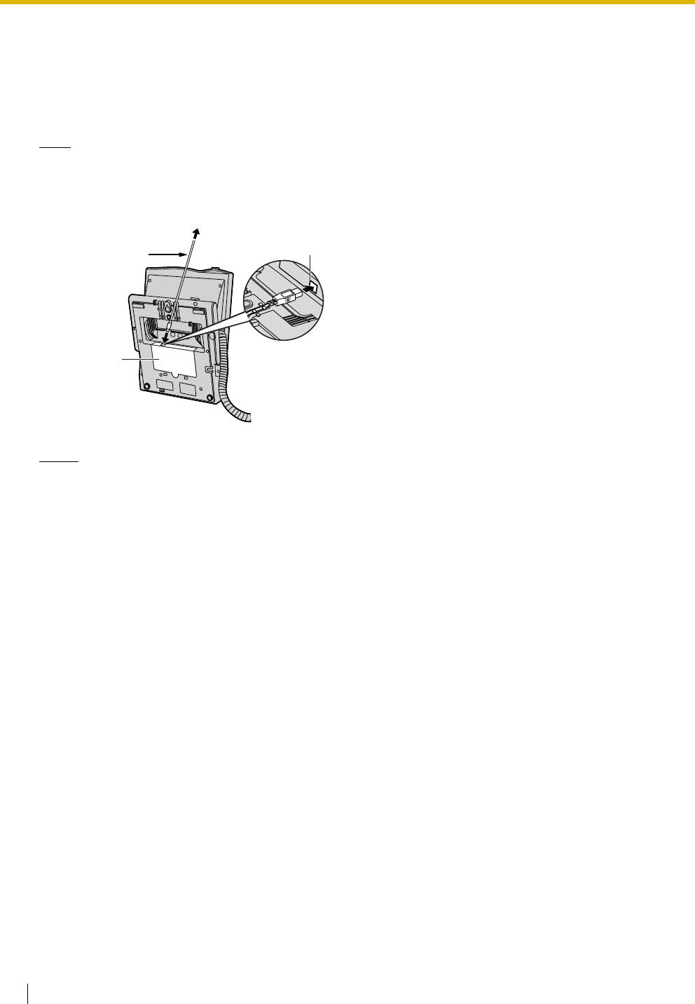
2.7 Connection of Extensions
144 Installation Manual
2.7.4 First Party Call Control CTI Connection
CTI connection between a PC and a KX-T7633/T7636 DPT provides first party call control. The CTI
connection is made via a USB interface (version 2.0), and uses the TAPI 2.1 protocol.
A USB Module (KX-T7601) must be connected to the KX-T7633/T7636 DPT.
Note
The operating system of the PC required for first party call control depends on your CTI application
software. For details, refer to the manual for your CTI application software.
Notes
• The maximum length of the USB cable is 3 m.
• USB Modules must not be connected to DPTs in the Digital XDP connection. In a Digital XDP
connection, the PC cannot be used. If a USB module is connected to a slave DPT, the DPT will not
work properly.
USB Cable
To P C
ULL
USB Port
USB Module

2.8 Connection of DECT Portable Stations
Installation Manual 145
2.8 Connection of DECT Portable Stations
2.8.1 Overview
The following equipment is required to connect the wireless system:
CS: Cell Station (KX-TDA0142CE/KX-TDA0141CE)
KX-TDA0142CE Using a CSIF Card
This unit determines the area covered by the wireless system. Up to 4 calls can be made at the same
time through each CS.
•CSIF4 (KX-TDA0143)
One CSIF4 card supports up to 4 Cell Stations.
•CSIF8 (KX-TDA0144)
One CSIF8 card supports up to 8 Cell Stations.
KX-TDA0141CE Using a DHLC/DLC Card
This unit determines the area covered by the wireless system. Up to 2 calls can be made at the same
time through each CS.
Note for users in Europe
This Cell Station Unit for DECT is for connection to Panasonic PBXs in use in European countries.
PS: DECT Portable Station (KX-TCA155/KX-TCA255/KX-TD7590/KX-TD7580)
The KX-TDA100 and KX-TDA200 can support up to 128 PSs. For more details about the PS, refer to the
PS Operating Instructions.
RF Specification
Item Description
Radio Access Method MultiCarrier TDMA-TDD
Frequency Band 1880 MHz to 1900 MHz*1
*1 KX-TDA100BX/KX-TDA200BX: 1880 MHz to 1895 MHz
Number of Carriers 10*2
Carrier Spacing 1728 kHz
Bit Rate 1152 kbps
Carrier Multiplex TDMA, 24 (Tx12, Rx12) slots per frame
Frame Length 10 ms
Modulation Scheme GFSK
Roll-off factor=0.5 50 % roll-off in the transmitter
Data Coding for Modulator Differential Coding
Voice CODEC 32 kbps ADPCM (CCITT G.721)
Transmission Output Average 10 mW
Peak 250 mW

2.8 Connection of DECT Portable Stations
146 Installation Manual
CAUTION
• The CS should be kept free of dust, moisture, high temperature (more than 40 ), low temperature
(less than 0 ), and vibration, and should not be exposed to direct sunlight.
• The CS should not be placed outdoors (use indoors).
• The CS should not be placed near high-voltage equipment.
• The CS should not be placed on a metal object.
• Do not use this wireless system near another high-power cordless system such as DECT or SS
wireless.
• Maintain the distances listed below between equipment in order to prevent noise, interference or
the disconnection of a conversation. (The distance may vary depending on the environment.)
*2 KX-TDA100BX/KX-TDA200BX: 8
Equipment Distance
CS and office equipment such as a computer, telex, fax
machine, etc., or microwaves
More than 2 m
CS and PS More than 1 m
Each PS More than 0.5 m
Hybrid IP-PBX and CS More than 2 m
Too many CSs in a small area can cause problems due to conflicts over which signal channels
each CS can use. Ideally, CSs should be a minimum of 25 m to 40 m apart.
However, the required distance between CSs may vary depending on the environment of the
installation site and conditions in which the wireless system is used. Conduct the site survey to
determine the appropriate distance.
˚
C
˚C
2.8 Connection of DECT Portable Stations
Installation Manual 147
2.8.2 Procedure Overview
When connecting the wireless system, use extreme care in conducting the site survey. Site surveys can be
conducted using the KX-TCA255 or KX-TD7590 PS. An incorrectly performed site survey can result in poor
service area, frequent noise, and disconnection of calls.
1. Investigate the installation site
Refer to "2.8.3 Site Planning".
a. Obtain a map of the CS installation site.
b. Identify the service area required by the user on the map.
c. Plan the location of each CS, taking account of distance, building materials, etc.
2. Prepare for site survey
Refer to "2.8.4 Before Site Survey".
a. Check and assign the CS ID number to the PS.
b. Assign a channel number to each CS by setting the DIP switches on the back of the CS.
c. Supply electricity to each CS using an AC adaptor or a battery box.
d. Install each CS temporarily as planned.
Notes
• Install at least 2 m above the floor.
• Keep the antennas in the upright position.
3. Conduct the site survey
Refer to "2.8.5 Site Survey Using the KX-TCA255/KX-TD7590".
a. Test the radio signal strength using the PS.
Confirm that the radio signal strength level is "12" near the CS.
Using the KX-TCA255
Using the KX-TD7590
b. By walking away from the CS with the PS, check the radio signal strength. The radio signal strength
weakens as you walk away from the CS.
c. Map the CS coverage area at radio signal strength levels "3" and "8".
d. Make sure that adjacent CS coverage areas overlap where the radio signal strength level is "8" by
at least 5 m.
Display example:
RADIO STRENGTH
<<< MEASURING >>>
RADIO STRENGTH
CH0 SLOT:06 SYNC
L:12 0000/0100
CS-ID:9005301234
Press 1, 9, and POWER
for more than 2 seconds.
19
9
0
0 to 9
Channel No.
To survey
specific channel
Display example:
RADIO STRENGTH
<<< MEASURING >>>
CH0 SLOT:06 SYNC
L:12 0000/0100
CS-ID:9005301234
Press 1, 9, and POWER
for more than 5 seconds.
19
9
0
0 to 9
Channel No.
To survey
specific channel

2.8 Connection of DECT Portable Stations
148 Installation Manual
e. Make sure that the radio signal strength level is greater than "3" at any location within the service
area required by the user.
4. Finish the site survey
Refer to "2.8.6 After Site Survey".
a. Return all DIP switches of each CS to the OFF position, and stop supplying power.
b. Turn off the PS.
5. Connect the CS and PS to the Hybrid IP-PBX and test the operation
Refer to "2.8.7 Connecting a Cell Station to the Hybrid IP-PBX".
a. Connect the CSs to the Hybrid IP-PBX.
b. Register the PSs to the Hybrid IP-PBX.
c. Walk around the service area while having a conversation using a registered PS. If noise is
frequent or conversations disconnect, relocate the CSs or install an additional CS.
6. Mount the CS on the wall
Refer to "2.8.8 Wall Mounting".
a. If there are no problems in testing, mount the CS on the wall.
2.8 Connection of DECT Portable Stations
Installation Manual 149
2.8.3 Site Planning
Choosing the best site for the CS requires careful planning and testing of essential areas. The best location
may not always be convenient for installation. Read the following information before installing the unit.
Understanding Radio Waves
Characteristics of Radio Waves
The transmission of radio waves and the CS coverage area depend on the structure and materials of the
building.
Office equipment, such as computers and fax machines, can interfere with radio waves. Such equipment
may create noise or interfere with the performance of the PS.
The illustration below shows the special transmitting patterns of radio waves.
1. Radio waves are reflected by objects made of materials such as metal.
2. Radio waves are diffracted by objects such as metallic columns.
3. Radio waves penetrate objects made of materials such as glass.
Relationships Between Radio Waves and Building Structure and Materials
• The CS coverage area is affected more by the building materials and their thickness than the number
of obstacles.
• Radio waves tend to be reflected or diffracted by conductive objects and rarely penetrate them.
• Radio waves tend to penetrate insulated objects and are rarely reflected by them.
• Radio waves penetrate thin objects more than thick objects.
• The table below shows the transmission tendency of radio waves when they reach objects made from
various materials.
CS
Column
3. Penetration
2. Diffraction
1. Reflection

2.8 Connection of DECT Portable Stations
150 Installation Manual
Object Material Transmission Tendency
Wall Concrete The thicker they are, the less radio waves
penetrate them.
Ferroconcrete Radio waves can penetrate them, but the more iron
there is, the more radio waves are reflected.
Window Glass Radio waves usually penetrate them.
Glass with wire net Radio waves can penetrate them, but tend to be
reflected.
Glass covered with heat-
resistant film
Radio waves are weakened considerably when
they penetrate windows.
Floor Ferroconcrete Radio waves can penetrate them, but the more iron
there is, the more radio waves are reflected.
Partition Steel Radio waves are reflected and rarely penetrate
them.
Plywood, Glass Radio waves usually penetrate them.
Column Ferroconcrete Radio waves can penetrate them, but the more iron
there is, the more radio waves tend to be reflected
or diffracted.
Metal Radio waves tend to be reflected or diffracted.
Cabinet Steel Radio waves are usually reflected or diffracted,
and rarely penetrate them.
Wood Radio waves can penetrate them, but they are
weakened.
2.8 Connection of DECT Portable Stations
Installation Manual 151
CS Coverage Area
The example below shows the size of the coverage area of 1 CS if it is installed in an area with no obstacles.
Note
Radio signal strength levels are measured during the site survey (refer to "2.8.5 Site Survey Using the
KX-TCA255/KX-TD7590").
Site Survey Preparation
1. Obtain a map and investigate the installation site.
a. Check the obstacles (e.g., shelves, columns, and partitions).
b. Check the materials of the structures (e.g., metal, concrete, and plywood).
c. Check the layout and dimensions of the room, corridor, etc.
d. Write down the above information on the map.
2. Examine the service area required by the user on the map, referring to the following example.
a. Draw the coverage area around a CS. Extend the coverage area 30 m to 60 m in each direction,
depending on the materials of the building structures and obstacles in the installation site. Note
that a CS cannot be installed outside a building.
b. If 1 CS cannot cover the entire service area, install additional CSs as required. Overlap the
coverage areas of adjacent CSs.
Gray Zone:
Conversation will be
intermittent
Coverage Area
Radio signal strength level is
greater than "3".
(About 50 m to 60 m)
Good Coverage Area
Radio signal strength
level is greater than "8".
(About 30 m to 40 m)
Good sound quality
can be maintained.
Out of Service:
Cannot make/receive calls
A
B
A
B
Radio Signal Strength Levels
C
Out of range
Receives noise easily or disconnects
May receive noise
Good
Better
Level: 00
Level: 01 to 02
Level: 03 to 07
Level: 08 to 10
Level: 11 to 12
2.8 Connection of DECT Portable Stations
152 Installation Manual
Where CS coverage areas overlap, the PS will start call handover to the next CS if the signal from
one CS becomes weak. However, if a PS moves away from a CS and there are no CSs available
for handover, the PS may go out of range and the call could be lost.
Example: Installing in a Room Separated by Interior Walls
Things to take note of:
• The room is separated by interior walls.
• The room is surrounded by concrete walls.
CS installation plan:
• The coverage area of each CS will not extend as far as when there are no obstacles, because the
radio signals will be weakened by separating walls. Therefore, you will need 5 CSs to cover the
entire room.
70 m
150 m
CS no. 5
CS no. 1
CS no. 2
CS no. 4
CS no. 3
2.8 Connection of DECT Portable Stations
Installation Manual 153
2.8.4 Before Site Survey
Use the KX-TCA255 or KX-TD7590 PS to conduct the site survey.
Note
Display prompts for the site survey are only available in English.
Checking the CS ID Number
Check the CS ID number label attached to the CS. If the CS ID number label is not attached to the CS, check
the CS ID number using the KX-TDA Maintenance Console. For details, refer to the on-line help of the KX-
TDA Maintenance Console.
Assigning the CS ID Number to the PS
Using the KX-TCA255
Note
To clear the CS ID number assigned to the PS, follow the procedure below:
Press 1, 9, and POWER
for more than 2 seconds. 0 to 7 0 to 9 and A to F
CS No. CS ID No.
19
9
2
ABC
To enter letters
A: + C: + E: +
B: + D: + F: +
To the initial display To the Desired CS No.
3
DEF
4
GHI
0
15
JKL
2
ABC
Press 1, 9, and POWER
for more than 2 seconds.
0 to 7
CS No.
19
9
3
DEF
To the Desired CS No.
OR
#
To clear one by one
To clear all at once
To the initial display
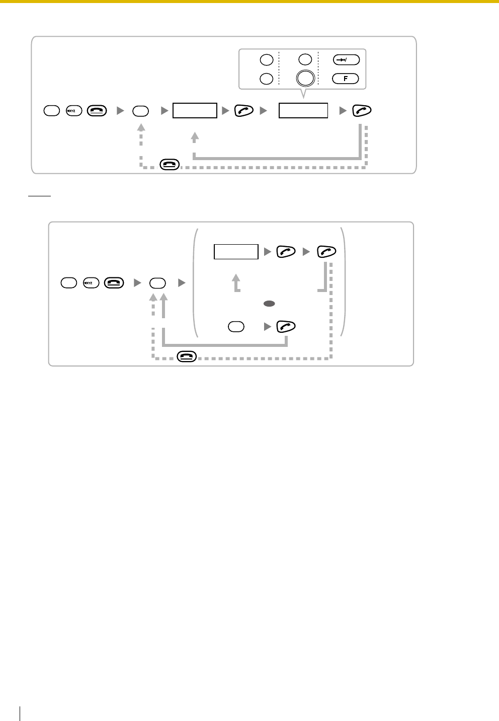
2.8 Connection of DECT Portable Stations
154 Installation Manual
Using the KX-TD7590
Note
To clear the CS ID number assigned to the PS, follow the procedure below:
Press 1, 9, and POWER
for more than 5 seconds. 0 to 7 0 to 9 and A to F
CS No. CS ID No.
19
9
2
ABC
To enter letters
F1
F2
F3
INT'
OK
A: C: E:
B: D: F:
To the initial display To the Desired CS No.
Press 1, 9, and POWER
for more than 5 seconds.
0 to 7
CS No.
19
9
3
DEF
To the Desired CS No.
OR
#
To clear one by one
To clear all at once
To the initial display
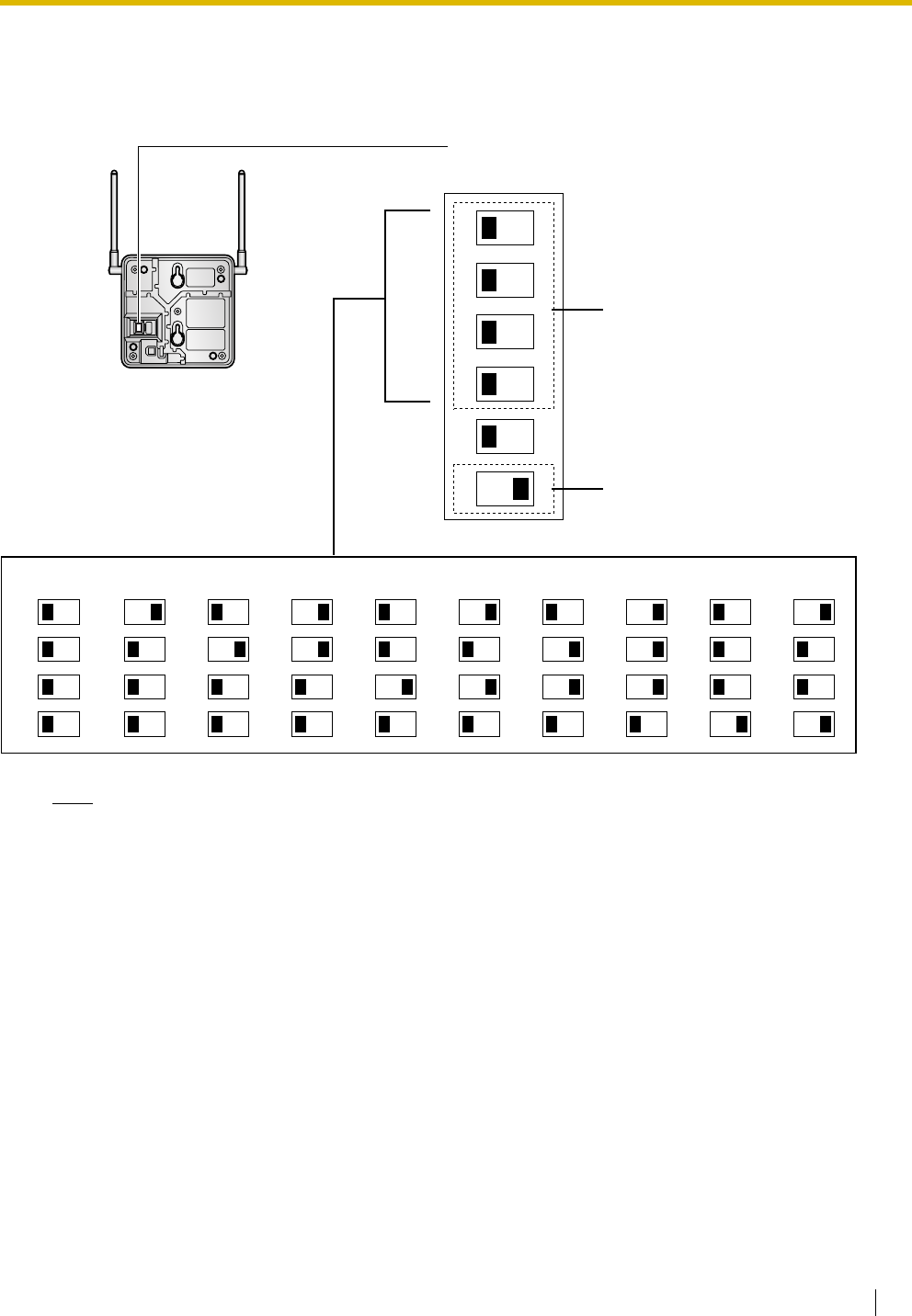
2.8 Connection of DECT Portable Stations
Installation Manual 155
Setting and Installing the CS Temporarily for Site Survey
1. Switch the Radio Signal Test switch from OFF to ON.
2. Set the channel number switches as desired.
Note
If more than 1 CS is in Radio Signal Test mode, each CS must have a unique channel number.
Channel Number Switch
Channel 1 Channel 2 Channel 3 Channel 4 Channel 5 Channel 6 Channel 7 Channel 8 Channel 9
1
2
3
4
1
2
3
4
1
2
3
4
1
2
3
4
1
2
3
4
1
2
3
4
1
2
3
4
1
2
3
4
1
2
3
4
DIP Switch
1
2
3
4
5
6
OFF ON
Radio Signal
Test Switch
Channel 0
1
2
3
4
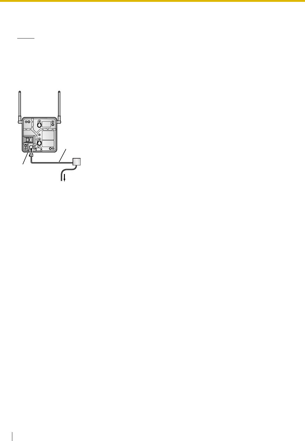
2.8 Connection of DECT Portable Stations
156 Installation Manual
3. After setting the DIP switch, connect an AC adaptor or battery box to the CS using a power supply
adaptor.
Notes
• The AC adaptor should be connected to a vertically oriented or floor-mounted AC outlet. Do not
connect the AC adaptor to a ceiling-mounted AC outlet, as the weight of the adaptor may cause it
to become disconnected.
•For users in the United Kingdom:
240 V AC must not be used on a building site. Instead of an AC adaptor, connect a battery box to
the CS.
4. Install the CS temporarily for the site survey. Install the CS at least 2 m above the floor, keeping the
antennas in the upright position.
To AC Adaptor (KX-A11/KX-TCA1)/
Battery Box (PSZZTD142CE)
Power Supply Adaptor
(PSZZ1TDA0142)
Modular
Telephone Cord
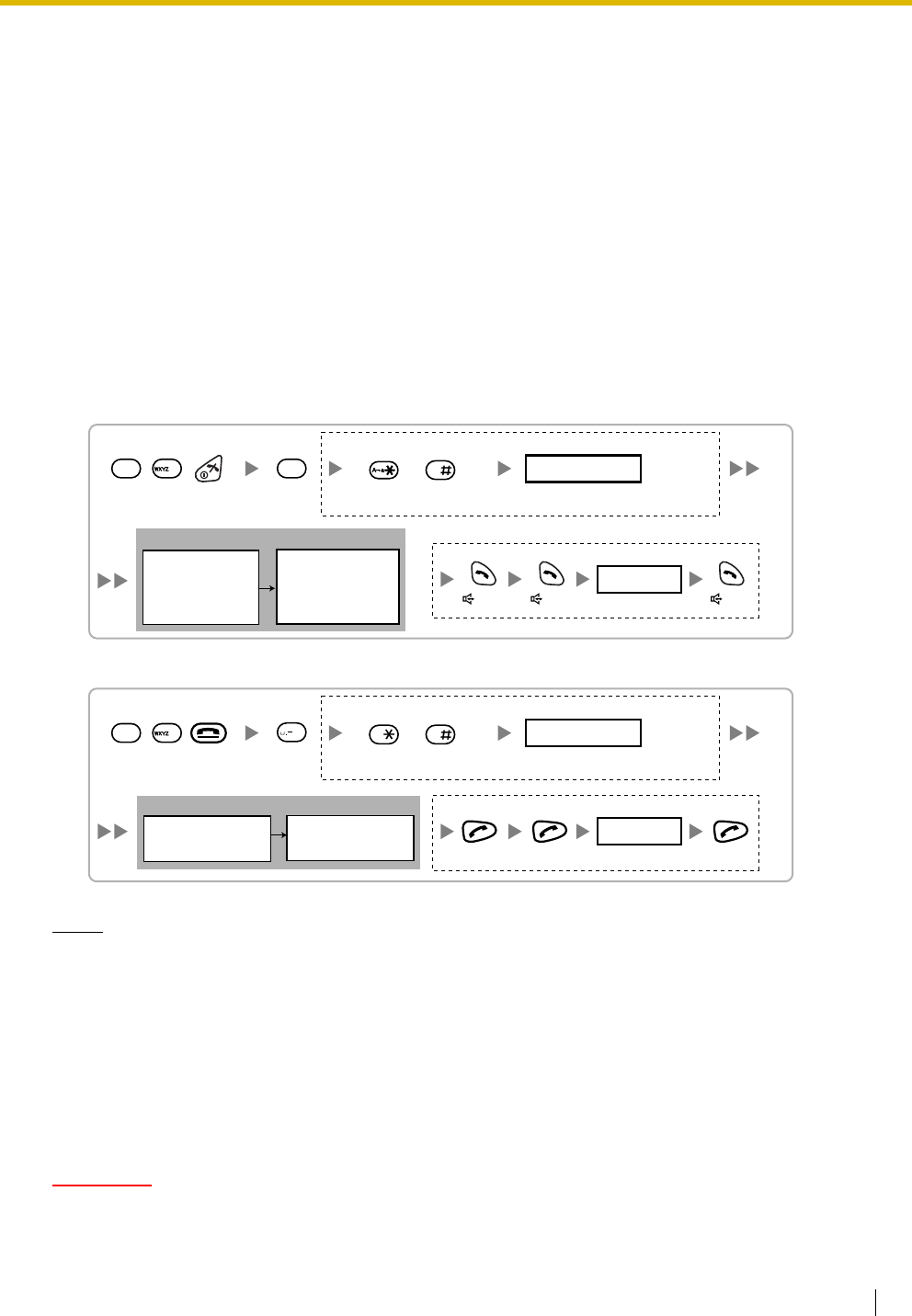
2.8 Connection of DECT Portable Stations
Installation Manual 157
2.8.5 Site Survey Using the KX-TCA255/KX-TD7590
The PS has a Radio Signal Test mode that monitors the state of the radio link to the CS for site survey. In
Radio Signal Test mode, the frame loss and signal strength of a synchronous slot, and the signal strength
of the other slots can be measured when the PS is monitoring the CS. After installing the CSs temporarily
as planned during site planning, set the PS to Radio Signal Test mode and locate each CS to measure its
coverage area. Then, record the results on the map of the installation site.
Testing the Radio Signal Strength
After locating the CS(s) temporarily, execute the Radio Signal Test using the PS. Directly after entering
Radio Signal Test mode, the PS scans channel 0 for a CS that it can connect to. The channel to be scanned
can be changed by pressing the appropriate keys 0 through 9.
1. Enter Radio Signal Test mode.
Using the KX-TCA255
Using the KX-TD7590
Notes
*1: Channel number
*2: Slot number
*3: When a slot is synchronised, "SYNC" is displayed.
*4: Radio signal strength level
*5: Frame error (0000 to 9999)/Frame counter (0000 to 9999). Frame error indicates the number of
errors out of 10 000 radio signal receptions. An increased number of frame errors indicates greater
radio signal interference and more frequent noise during conversation. The ideal number of frame
errors is "0000".
CAUTION
Storing the scan data will clear all directory data.
2. Measure the radio signal strength by moving towards and away from the CS.
0 to 9
Log No.
To store the scan data
Press 1, 9, and POWER
for more than 2 seconds.
19
9
Previous or Next 0 to 9
Channel No.
To survey other slots To survey specific channel
/
RADIO STRENGTH
<<< MEASURING >>>
RADIO STRENGTH
CH0
*1
SLOT:06
*2
SYNC
*3
L:12
*4
0000/0100
*5
CS-ID:9005301234
0
Display example:
Display example:
RADIO STRENGTH
<<< MEASURING >>>
CH0
*1
SLOT:06
*2
SYNC
*3
L:12
*4
0000/0100
*5
CS-ID:9005301234
0 to 9
Log No.
To store the scan data
Press 1, 9, and POWER
for more than 5 seconds.
19
9
0
Previous or Next 0 to 9
Channel No.
To survey other slots To survey specific channel
/
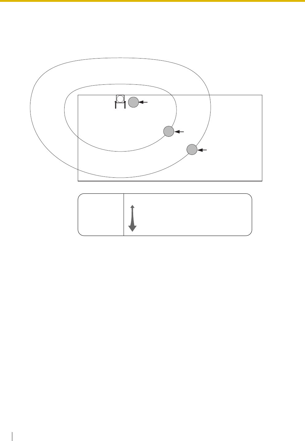
2.8 Connection of DECT Portable Stations
158 Installation Manual
a. Move to the CS until the radio signal strength level becomes "12".
b. Move away from the CS and identify the CS coverage area within which the radio signal strength
level is greater than "8". Draw the area on the map.
c. Move away from the CS and identify the CS coverage area within which the radio signal strength
level is greater than "3". Draw the area on the map.
Channel no. 0
PS
PS
PS CH0
L:03
CH0
L:12
Radio Signal Strength Levels
Out of range
Receives noise easily or disconnects
May receive noise
Good
Better
Level: 00
Level: 01 to 02
Level: 03 to 07
Level: 08 to 10
Level: 11 to 12
CH0
L:08
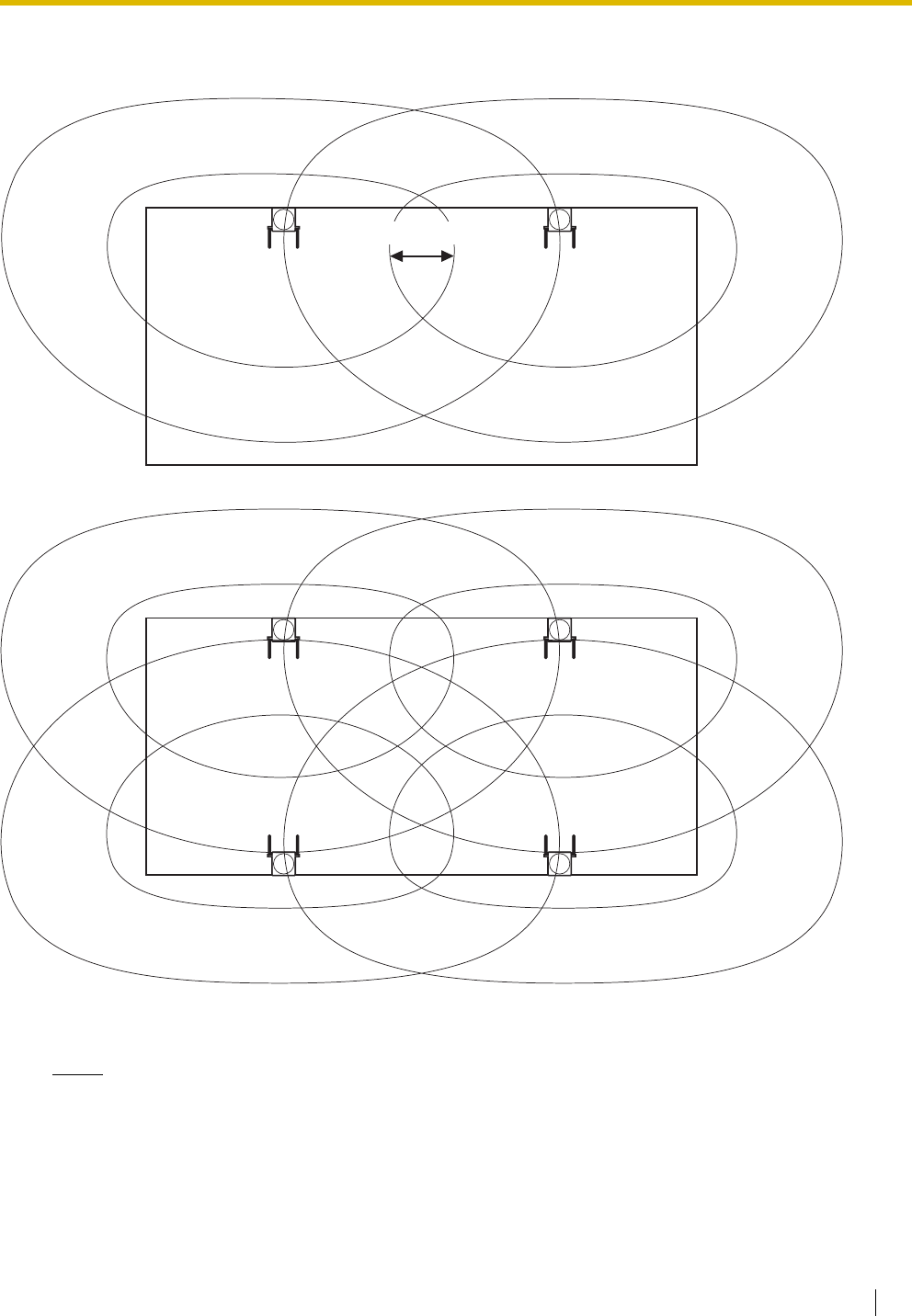
2.8 Connection of DECT Portable Stations
Installation Manual 159
3. Repeat steps 1 and 2 for other CSs, and relocate the CSs when necessary.
a. Overlap adjacent CS coverage areas where the radio signal strength level is "8" by 5 m to 10 m.
b. Overlap the CS coverage areas of at least 2 CSs at any location in the installation site.
c. Make sure that the radio signal strength level is greater than "3" at any location in the service area
required by the user.
Notes
• If a channel is set, the results of measurement for the 24 slots on the channel are saved each time.
If the same channel is set, the new results override the previous ones. Therefore, a measurement
of 10 channels × 24 slots in total can be made.
• If correct results cannot be obtained (e.g., there are many frame errors), change the location of the
CS and repeat the site survey to select the best location.
5 m to 10 m
Channel no. 0 Channel no. 1
Channel no. 0 Channel no. 1
Channel no. 2 Channel no. 3
2.8 Connection of DECT Portable Stations
160 Installation Manual
Referring to the Stored Scan Data
Using the KX-TCA255
Using the KX-TD7590
Clearing the Stored Scan Data
When "CLEAR SCAN DATA" is displayed after turning on the PS, you are required to clear the scan data.
Using the KX-TCA255
Using the KX-TD7590
Press 1, 9, and POWER
for more than 2 seconds. 0 to 9
Log No.
19
1
Previous or Next 0 to 9
Channel No.
To go to other slots To go to specific channel
/
A a
Press 1, 9, and POWER
for more than 5 seconds. 0 to 9
Log No.
19
1
Previous or Next 0 to 9
Channel No.
To go to other slots To go to specific channel
/
Press 1, 9, and POWER
for more than 2 seconds.
19
4
GHI
Press 1, 9, and POWER
for more than 5 seconds.
19
4
GHI

2.8 Connection of DECT Portable Stations
Installation Manual 161
2.8.6 After Site Survey
After obtaining the proper measurement results, exit Radio Signal Test mode before connecting the CS to
the Hybrid IP-PBX.
1. Keep pressing the POWER button on the PS until the PS is turned OFF.
2. Disconnect the AC adaptor or battery box from the CS and stop supplying electricity.
3. Switch all DIP switches on the CS from ON to OFF.
1
2
3
4
5
6
OFF ON

2.8 Connection of DECT Portable Stations
162 Installation Manual
2.8.7 Connecting a Cell Station to the Hybrid IP-PBX
Using a CSIF Card
Refer to the following example to connect a CS to the Hybrid IP-PBX.
Accessories and User-supplied Items for the CS
Accessories (included): Screws × 2, Washers × 2, Ferrite core × 1
User-supplied (not included): RJ11 connector
Note
For details about CSIF card, refer to "2.5.1 CSIF4 Card (KX-TDA0143) and CSIF8 Card (KX-
TDA0144)".
Signal Name
Signal Name Pin No.
1
2
3
4
D1
POWH
POWL
D2
D1
POWH
POWL
D2
Pin No.
1
2
3
4
5
6
7
8
CSIF card (RJ45)
CS (RJ11)
Cable Maximum Distance
ø 0.4 mm: 444 m
ø 0.5 mm: 694 m
ø 0.6 mm: 1000 m
CAT 5: 694 m
Port 1
CSIF8 Card

2.8 Connection of DECT Portable Stations
Installation Manual 163
Using a DHLC/DLC Card
Refer to the following example to connect a CS to the Hybrid IP-PBX.
Accessories and User-supplied Items for the CS
Accessories (included): Screws × 2, Washers × 2
User-supplied (not included): RJ11 connector
Note
For details about DHLC card or DLC card, refer to "2.5.2 DHLC8 Card (KX-TDA0170)", "2.5.3 DLC8
Card (KX-TDA0171)", or "2.5.4 DLC16 Card (KX-TDA0172)" .
Signal Name
D1
D2
DHLC/DLC card
(Amphenol)
Cable Maximum Distance
ø 0.4 mm: 222 m
ø 0.5 mm: 347 m
ø 0.6 mm: 500 m
CAT 5: 347 m
Signal Name Pin No.
1
2
3
4
D1
D2
CS (RJ11)
DHLC8 Card

2.8 Connection of DECT Portable Stations
164 Installation Manual
Connecting the CS
1. Connect the cable from the CSIF/DHLC/DLC card to the CS.
2. Pass the cable through the groove of the CS (in any direction depending on your preference).
Modular
To CSIF/DHLC/DLC card
To CSIF/DHLC/DLC card
TO MAIN UNIT
/ PABX
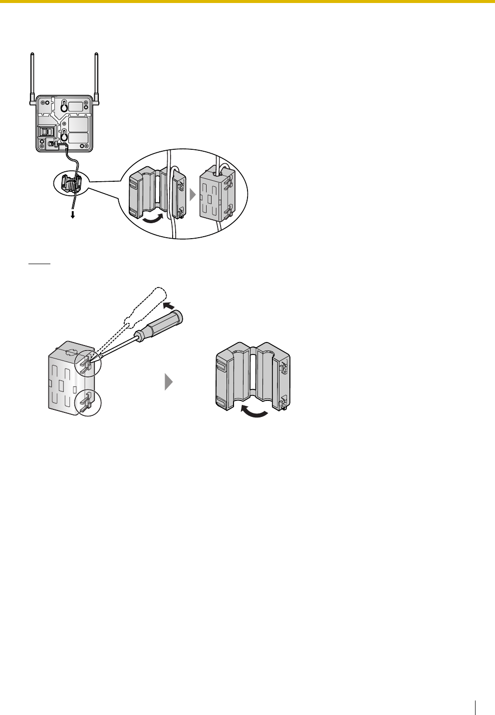
2.8 Connection of DECT Portable Stations
Installation Manual 165
For the KX-TDA0142CE User only:
3. Wrap the cable once around the ferrite core. Then close the case of the ferrite core.
Note
If you need to open the ferrite core, use a flathead screwdriver to unlatch the case of the ferrite core.
To CSIF card
2.8 Connection of DECT Portable Stations
166 Installation Manual
Registering the PS
The PS must be registered to the Hybrid IP-PBX before it can be used. Programming of both the PS and
Hybrid IP-PBX is required. A PT with multiline display (e.g., KX-T7636 6-line display) is required to perform
the Hybrid IP-PBX system programming.
Note
For details about system programming using a PT, refer to "2.3.2 PT Programming" in the Feature
Guide, and "2.1 PT Programming" in the PT Programming Manual.
Entering the Hybrid IP-PBX System Programming Mode Using a PT
Administrator Level
Note
means default value.
PS Registration
One PS can be registered to a maximum of 4 different Hybrid IP-PBXs.
Using the KX-TCA155/KX-TCA255
#
= 1234
System Password for Administrator—
for PT Programming Programming No.
3 digits
PROGRAM/
PAUSE
[690]
001 to 128
PS No.
1 to 4 digits END
ENTER ENTER
To the PS
operation
below
Extn. No.
Select
"Setting Handset".
Select
"Register H/set".
Select
"Registration".
Select
"Base 1–4".
"Please wait".
"Enter Base PIN".
Press POWER
for 2 seconds.
C.Tone
4 digits
PIN for PS Registration
2.8 Connection of DECT Portable Stations
Installation Manual 167
Using the KX-TD7590
System lock can be set after PS registration. When system lock is enabled, the system lock password
will be required for system setting.
Using the KX-TD7580
Select
"DECT-SYS1-4" 4 digits
Choose
"ENABLE/DISABLE".
PIN for
PS Registration
System Lock Password
System Lock Password
Press POWER
for 5 seconds.
4 digits
4 digits
ENABLE
F
/
/
SELECT
SELECT
SELECT
/OK
/OK
/OK
C.Tone
To set system lock
F
DISABLE
OR
To register for the first time
To re-register
/
Select
"INITIAL SETTING".
SELECT
/
Select
"PS-PROGRAM".
SELECT
/
Select "DECT-
SYS SETTING".
SELECT
4 digits
If required
/OK
System Lock Password
Select
"REGISTRATION".
/
/
Select
"Setting Handset".
Select
"Register H/set".
Select
"Registration".
Select
"Base 1–4".
Press POWER
for 2 seconds.
/
/
/
C.Tone
4 digits
PIN for
PS Registration
2.8 Connection of DECT Portable Stations
168 Installation Manual
Setting the Personal Identification Number (PIN) for PS Registration
To prevent registering the PS to a wrong Hybrid IP-PBX, a PIN for PS registration can be set to the Hybrid
IP-PBX. Before registering the PS to the Hybrid IP-PBX, enter the PIN set to the Hybrid IP-PBX into the PS.
By doing so, the PS will only be registered to the Hybrid IP-PBX with the matching PIN.
Notes
• By default, the PIN for PS registration is "1234" for both the Hybrid IP-PBX and PS. Therefore, the
PS can be registered to the Hybrid IP-PBX without setting the PIN.
• The PIN for PS registration will only be used when registering the PS to the Hybrid IP-PBX.
Therefore, during normal operation after registration, even if there is more than 1 Hybrid IP-PBX
with the same PIN near the PS, the PS will not be inadvertently linked to a different Hybrid IP-PBX.
Setting the PIN for Hybrid IP-PBX
Changing the Display Language of the PS
Using the KX-TCA155/KX-TCA255
Using the KX-TD7590
Using the KX-TD7580
[692]
4 digits
PIN for PS Registration
END
ENTER ENTER
1234
Select
"Setting Handset".
Select
"
Select Language
".
Select
"Display Option".
Select the desired
language
.
Press POWER
for 2 seconds.
/
Select
"DISPLAY SETTING".
Select the desired
language.
Select
"LANGUAGE".
Press POWER
for 5 seconds.
F
/
/
SELECT
SELECT
SELECT
0
SELECT
/
Select
"Setting Handset".
Select "Select
Language".
Select
"Display Option".
Select the desired
language.
Press POWER
for 2 seconds.
/
/
/
2.8 Connection of DECT Portable Stations
Installation Manual 169
PS Termination
Confirm the following before cancelling the PS registration:
• The PS is turned on.
• The PS is within range.
If the registration information is still stored in the PS
Using the KX-TCA155/KX-TCA255
Using the KX-TD7590
Using the KX-TD7580
[691]
001 to 128
PS No.
ENTER ENTER
END
To the PS
operation
below
If "Rejected" or "Time out" is displayed
CLEAR YES
Press "YES".Press "CLEAR".
4 digits
Handset PIN
Select
"Setting Handset".
Select
"Registration".
Select
"Base 1–4".
Press POWER
for 2 seconds.
C.Tone
Select
"YES".
Select
"Cancel Base".
Select the
desired item.
F
/
0
/
Select "DECT-
SYS SETTING".
SELECT
4 digits
If required
/OK
System Lock Password
/
Select "CANCEL
DECT-SYS".
SELECT
SELECT
/
Select "YES".
C.Tone
Press POWER
for 5 seconds.
SELECT
/
Select
"Setting Handset".
Select
"Cancel Base".
Select
"Registration".
Press POWER
for 2 seconds.
/
/
C.Tone
4 digits
Handset PIN
Select the
desired item.
/
Select "YES".
/

2.8 Connection of DECT Portable Stations
170 Installation Manual
Testing the Operation
Walk around the service area while having a conversation using a registered PS. If noise is frequent or
conversations disconnect, relocate the CSs or install an additional CS.
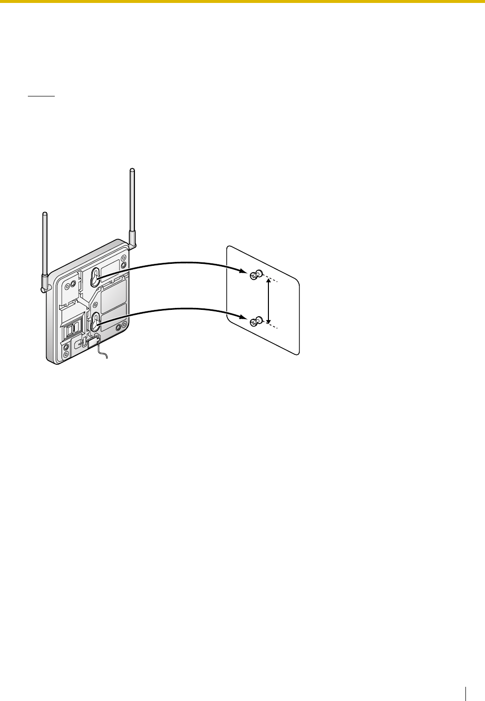
2.8 Connection of DECT Portable Stations
Installation Manual 171
2.8.8 Wall Mounting
1. Place the reference for wall mounting (on the following page) on the wall to mark the 2 screw positions.
2. Install the 2 screws and washers (included) into the wall.
Notes
• Make sure that the screw heads are at the same distance from the wall.
• Install the screws perpendicular to the wall.
3. Hook the CS on the screw heads.
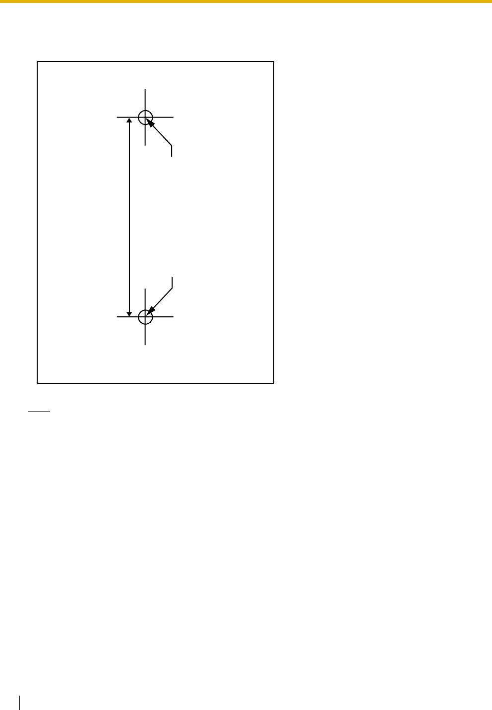
2.8 Connection of DECT Portable Stations
172 Installation Manual
Reference for Wall Mounting
Please copy this page and use as a reference for wall mounting.
Note
Make sure to set the print size to correspond with the size of this page. If the dimension of the paper
output still deviates slightly from the measurement indicated here, use the measurement indicated
here.
Install a screw here.
Install a screw here.
71 mm

2.9 Connection of 2.4 GHz Portable Stations
Installation Manual 173
2.9 Connection of 2.4 GHz Portable Stations
2.9.1 Overview
The following equipment is required to connect the wireless system:
CS: Cell Station (KX-TDA0142/KX-TDA0141)
KX-TDA0142 Using a CSIF Card
This unit determines the area covered by the wireless system. Up to 3 calls can be made at the same
time through each CS.
•CSIF4 (KX-TDA0143)
One CSIF4 card supports up to 4 Cell Stations.
•CSIF8 (KX-TDA0144)
One CSIF8 card supports up to 8 Cell Stations.
KX-TDA0141 Using a DHLC/DLC Card
This unit determines the area covered by the wireless system. Up to 2 calls can be made at the same
time through each CS.
PS: 2.4 GHz Portable Station (KX-TD7680/KX-TD7690)
The KX-TDA100 and KX-TDA200 can support up to 128 PSs. For more details about the PS, refer to the
PS Operating Instructions.
CAUTION
• The CS should be kept free of dust, moisture, high temperature (more than 40 ), low temperature
(less than 0 ), and vibration, and should not be exposed to direct sunlight.
• The CS should not be placed outdoors (use indoors).
• The CS should not be placed near high-voltage equipment.
• The CS should not be placed on a metal object.
• Systems using 2.4 GHz ISM (Industrial, Scientific and Medical) band may interfere with the KX-
TDA wireless system. Examples of such systems are cordless telephones, wireless LAN, Home
RF, microwave ovens and other ISM devices. These systems may cause minor noise.
• Keeping some distance between the equipment listed below may prevent interference. (The
distance may vary depending on the environment.)
Equipment Distance
CS and office equipment such as a computer, telex, fax
machine, etc.
More than 2 m
CS and PS More than 1 m
Each PS More than 0.5 m
Hybrid IP-PBX and CS More than 2 m
CS and CS More than 15 m
˚
C
˚
C

2.9 Connection of 2.4 GHz Portable Stations
174 Installation Manual
Please take into consideration the distance between the CSs when site planning. Please consult
a certified dealer for details.
However, the required distance between CSs may vary depending on the environment of the
installation site and conditions in which the wireless system is used. Conduct the site survey to
determine the appropriate distance.
2.9 Connection of 2.4 GHz Portable Stations
Installation Manual 175
2.9.2 Procedure Overview
When connecting the wireless system, use extreme care in conducting the site survey. An incorrectly
performed site survey can result in poor service area, frequent noise, and disconnection of calls.
1. Investigate the installation site
Refer to "2.9.3 Site Planning".
a. Obtain a map of the CS installation site.
b. Identify the service area required by the user on the map.
c. Plan the location of each CS, taking account of distance, building materials, etc.
2. Prepare the CS for site survey
Refer to "2.9.4 Before Site Survey".
a. Assign a CS number to each CS by setting the DIP switches on the back of the CS.
b. Supply electricity to each CS using an AC adaptor or a battery box.
c. Install each CS temporarily as planned.
Notes
• Install at least 2 m above the floor.
• Keep the antennas in the upright position.
3. Conduct the site survey
Refer to "2.9.5 Site Survey".
a. Test the radio signal strength using the PS.
Confirm that the radio signal strength level is "12" near the CS.
Using the KX-TD7680
Using the KX-TD7690
b. By walking away from the CS with the PS, check the radio signal strength. The radio signal strength
weakens as you walk away from the CS.
c. Map the CS coverage area at radio signal strength levels "3" and "8".
d. Make sure that adjacent CS coverage areas overlap where the radio signal strength level is "8" by
at least 5 m.
e. Make sure that the radio signal strength level is greater than "3" at any location within the service
area required by the user.
Display example:
Press 1, 9, and POWER
for more than 2 seconds.
<< SEARCHING >>
CS NO.1 LEVEL:12
SAVE:0123456789
1 to 9
CS No.
1
9
0
Display example:
Press 1, 9, and POWER
for more than 2 seconds.
<< SEARCHING >>
CS NO.1 LEVEL:12
SAVE:0123456789
1 to 9
CS No.
19
9

2.9 Connection of 2.4 GHz Portable Stations
176 Installation Manual
4. Finish the site survey
Refer to "2.9.6 After Site Survey".
a. Return all DIP switches of each CS to the OFF position, and stop supplying power.
b. Turn off the PS.
5. Connect the CS and PS to the Hybrid IP-PBX and test the operation
Refer to "2.9.7 Connecting a Cell Station to the Hybrid IP-PBX".
a. Connect the CSs to the Hybrid IP-PBX.
b. Register the PSs to the Hybrid IP-PBX.
c. Walk around the service area while having a conversation using a registered PS. If noise is
frequent or conversations disconnect, relocate the CSs or install an additional CS.
6. Mount the CS on the wall
Refer to "2.9.8 Wall Mounting".
a. If there are no problems in testing, mount the CS on the wall.
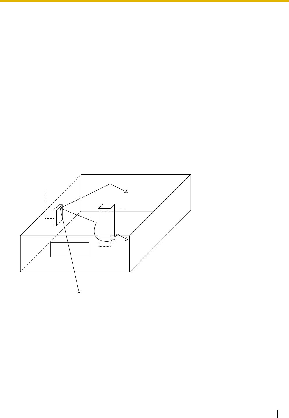
2.9 Connection of 2.4 GHz Portable Stations
Installation Manual 177
2.9.3 Site Planning
Choosing the best site for the CS requires careful planning and testing of essential areas. The best location
may not always be convenient for installation. Read the following information before installing the unit.
Understanding Radio Waves
Characteristics of Radio Waves
The transmission of radio waves and the CS coverage area depend on the structure and materials of the
building.
Office equipment, such as computers and fax machines, can interfere with radio waves. Such equipment
may create noise or interfere with the performance of the PS.
The illustration below shows the special transmitting patterns of radio waves.
1. Radio waves are reflected by objects made of materials such as metal.
2. Radio waves are diffracted by objects such as metallic columns.
3. Radio waves penetrate objects made of materials such as glass.
Relationships Between Radio Waves and Building Structure and Materials
• The CS coverage area is affected more by the building materials and their thickness than the number
of obstacles.
• Radio waves tend to be reflected or diffracted by conductive objects and rarely penetrate them.
• Radio waves tend to penetrate insulated objects and are rarely reflected by them.
• Radio waves penetrate thin objects more than thick objects.
• The table below shows the transmission tendency of radio waves when they reach objects made from
various materials.
CS
Column
3. Penetration
2. Diffraction
1. Reflection

2.9 Connection of 2.4 GHz Portable Stations
178 Installation Manual
Object Material Transmission Tendency
Wall Concrete The thicker they are, the less radio waves
penetrate them.
Ferroconcrete Radio waves can penetrate them, but the more iron
there is, the more radio waves are reflected.
Window Glass Radio waves usually penetrate them.
Glass with wire net Radio waves can penetrate them, but tend to be
reflected.
Glass covered with heat-
resistant film
Radio waves are weakened considerably when
they penetrate windows.
Floor Ferroconcrete Radio waves can penetrate them, but the more iron
there is, the more radio waves are reflected.
Partition Steel Radio waves are reflected and rarely penetrate
them.
Plywood, Glass Radio waves usually penetrate them.
Column Ferroconcrete Radio waves can penetrate them, but the more iron
there is, the more radio waves tend to be reflected
or diffracted.
Metal Radio waves tend to be reflected or diffracted.
Cabinet Steel Radio waves are usually reflected or diffracted,
and rarely penetrate them.
Wood Radio waves can penetrate them, but they are
weakened.
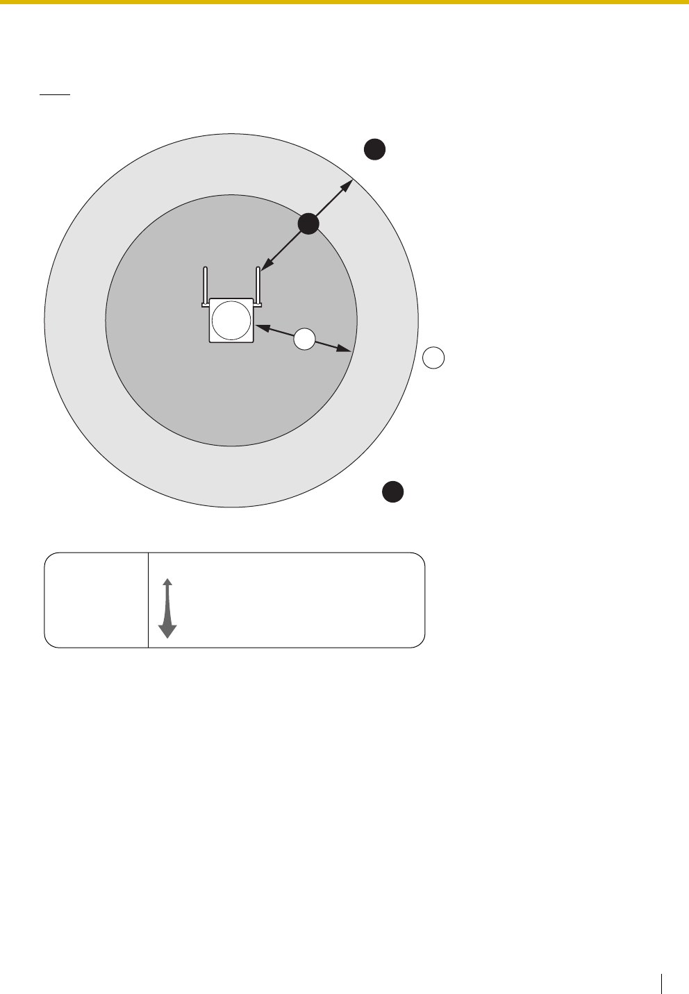
2.9 Connection of 2.4 GHz Portable Stations
Installation Manual 179
CS Coverage Area
The example below shows the size of the coverage area of 1 CS if it is installed in an area with no obstacles.
Note
Radio signal strength levels are measured during the site survey (refer to "2.9.5 Site Survey").
Site Survey Preparation
1. Obtain a map and investigate the installation site.
a. Check the obstacles (e.g., shelves, columns, and partitions).
b. Check the materials of the structures (e.g., metal, concrete, and plywood).
c. Check the layout and dimensions of the room, corridor, etc.
d. Write down the above information on the map.
2. Examine the service area required by the user on the map, referring to the following example.
a. Draw the coverage area around a CS. Extend the coverage area 30 m to 60 m in each direction,
depending on the materials of the building structures and obstacles in the installation site. Note
that a CS cannot be installed outside a building.
b. If one CS cannot cover the entire service area, install additional CSs as required. Overlap the
coverage areas of adjacent CSs.
Where CS coverage areas overlap, the PS will start call handover to the next CS if the signal from
Gray Zone:
Conversation will be
intermittent
Coverage Area
Radio signal strength level is
greater than "3".
(About 50 m to 60 m)
Good Coverage Area
Radio signal strength
level is greater than "8".
(About 30 m to 40 m)
Good sound quality
can be maintained.
Out of Service:
Cannot make/receive calls
A
B
A
B
Radio Signal Strength Levels
C
Out of range
Receives noise easily or disconnects
May receive noise
Good
Better
Level: 00
Level: 01 to 02
Level: 03 to 07
Level: 08 to 10
Level: 11 to 12
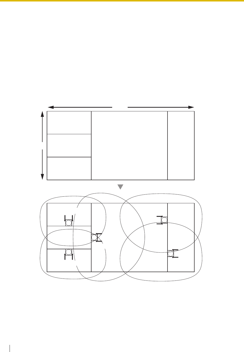
2.9 Connection of 2.4 GHz Portable Stations
180 Installation Manual
one CS becomes weak. However, if a PS moves away from a CS and there are no CSs available
for handover, the PS may go out of range and the call could be lost.
If the signal from the CS fades, due to the structure of the building, there may be some handover
delay. The user will hear a range warning before handover in this case. This also applies in the case
of interference from 2.4 GHz apparatus.
Example: Installing in a Room Separated by Interior Walls
Things to take note of:
• The room is separated by interior walls.
• The room is surrounded by concrete walls.
CS installation plan:
• The coverage area of each CS will not extend as far as when there are no obstacles, because the
radio signals will be weakened by separating walls. Therefore, you will need 5 CSs to cover the
entire room.
70 m
150 m
CS no. 5
CS no. 1
CS no. 2
CS no. 4
CS no. 3
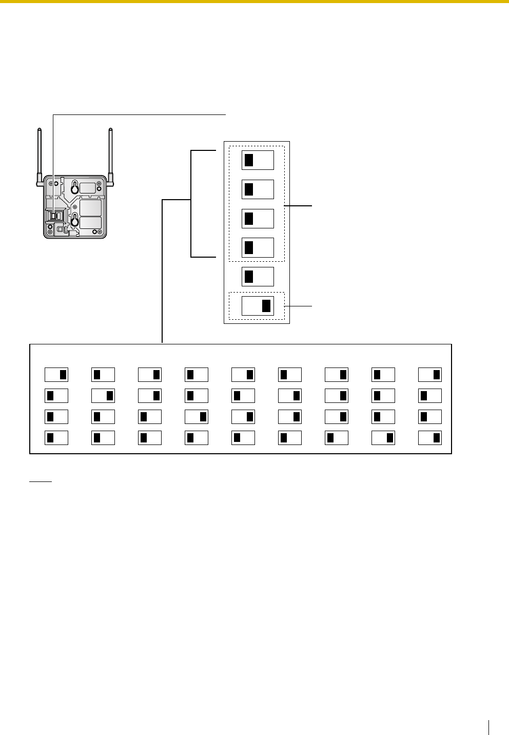
2.9 Connection of 2.4 GHz Portable Stations
Installation Manual 181
2.9.4 Before Site Survey
Setting and Installing the CS Temporarily for Site Survey
1. Switch the Radio Signal Test switch from OFF to ON.
2. Set the CS number switches as desired.
Note
If more than 1 CS is in Radio Signal Test mode, each CS must have a unique CS number.
CS Number Switch
CS no. 1 CS no. 2 CS no. 3 CS no. 4 CS no. 5 CS no. 6 CS no. 7 CS no. 8 CS no. 9
1
2
3
4
1
2
3
4
1
2
3
4
1
2
3
4
1
2
3
4
1
2
3
4
1
2
3
4
1
2
3
4
1
2
3
4
DIP Switch
1
2
3
4
5
6
OFF ON
Radio Signal
Test Switch
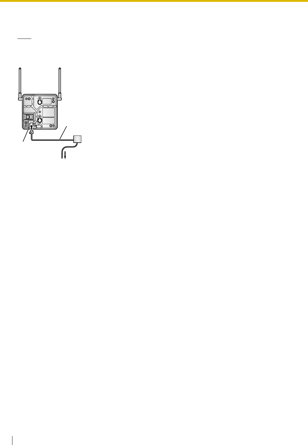
2.9 Connection of 2.4 GHz Portable Stations
182 Installation Manual
3. After setting the DIP switch, connect an AC adaptor or battery box to the CS using a power supply
adaptor.
Note
The AC adaptor should be connected to a vertically oriented or floor-mounted AC outlet. Do not connect
the AC adaptor to a ceiling-mounted AC outlet, as the weight of the adaptor may cause it to become
disconnected.
4. Install the CS temporarily for the site survey. Install the CS at least 2 m above the floor, keeping the
antennas in the upright position.
To AC Adaptor (KX-A11/KX-TCA1)/
Battery Box (PSZZTD142CE)
Power Supply Adaptor
(PSZZ1TDA0142)
Modular
Telephone Cord
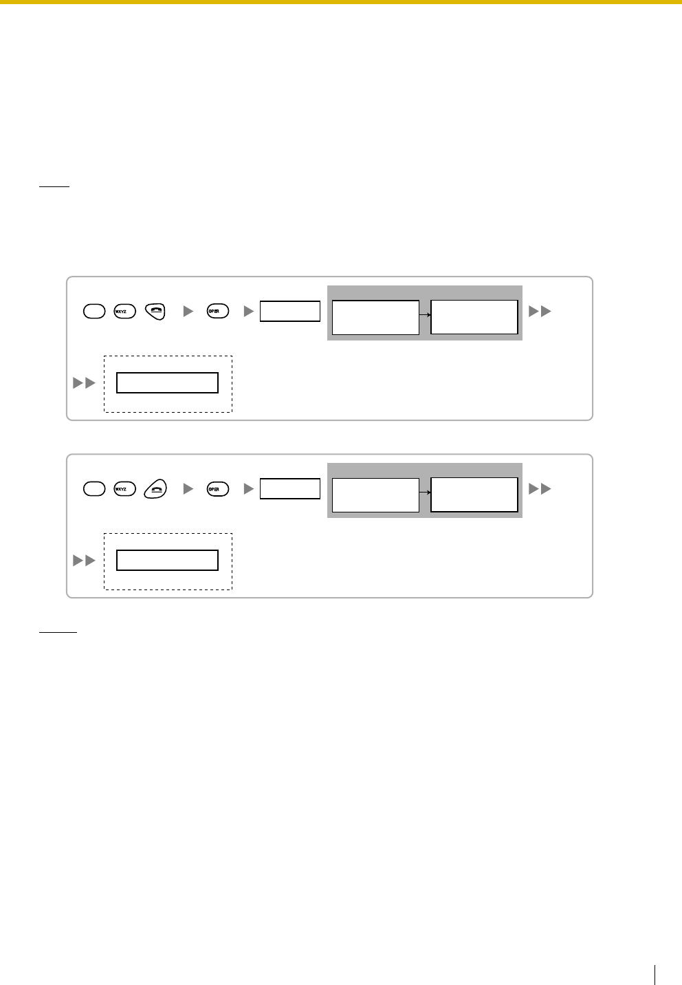
2.9 Connection of 2.4 GHz Portable Stations
Installation Manual 183
2.9.5 Site Survey
The PS has a Radio Signal Test mode that monitors the state of the radio link to the CS. After installing the
CSs temporarily, set the PS to Radio Signal Test mode and measure each CS coverage area. Then, record
the results on the map of the installation site.
Testing the Radio Signal Strength
Note
Display prompts for the site survey are only available in English.
1. Enter Radio Signal Test mode.
Using the KX-TD7680
Using the KX-TD7690
Notes
*1: CS number and radio signal strength level.
*2: Scan data (test result) number. Empty memory space will be indicated by a number; stored memory
space will be indicated by a "-".
Display example:
Press 1, 9, and POWER
for more than 2 seconds.
<< SEARCHING >>
CS NO.1 LEVEL:12
*1
SAVE:0123456789
*2
1 to 9
CS No.
19
9
0 to 9
Scan Data No.
To store the scan data
0
Display example:
Press 1, 9, and POWER
for more than 2 seconds.
<< SEARCHING >>
CS NO.1 LEVEL:12
*1
SAVE:0123456789
*2
1 to 9
CS No.
19
9
0 to 9
Scan Data No.
To store the scan data
0
2.9 Connection of 2.4 GHz Portable Stations
184 Installation Manual
2. Measure the radio signal strength by moving towards and away from the CS.
a. Move to the CS until the radio signal strength level becomes "12".
b. Move away from the CS and identify the CS coverage area within which the radio signal strength
level is greater than "8". Draw the area on the map.
c. Move away from the CS and identify the CS coverage area within which the radio signal strength
level is greater than "3". Draw the area on the map.
3. Repeat steps 1 and 2 for other CSs, and relocate the CSs when necessary.
a. Overlap adjacent CS coverage areas where the radio signal strength level is "8" by 5 m to 10 m.
CS no. 1
PS
PS
PS
CS NO.1 LEVEL: 3
CS NO.1 LEVEL: 12
Radio Signal Strength Levels
CS NO.1 LEVEL: 8
Out of range
Receives noise easily or disconnects
May receive noise
Good
Better
Level: 00
Level: 01 to 02
Level: 03 to 07
Level: 08 to 10
Level: 11 to 12
5 m to 10 m
CS no. 1 CS no. 2
2.9 Connection of 2.4 GHz Portable Stations
Installation Manual 185
b. Overlap the CS coverage areas of at least 2 CSs at any location in the installation site.
c. Make sure that the radio signal strength level is greater than "3" at any location in the service area
required by the user.
Referring to the Stored Scan Data
Using the KX-TD7680
Using the KX-TD7690
CS no. 1 CS no. 2
CS no. 3 CS no. 4
Press 1, 9, and POWER
for more than 2 seconds. 0 to 9
Scan Data No.
19
1
Display example:
When there is scan data
When there is no scan data
NO.1
CS No.2 LEVEL: 9
NO.0
NOT SAVED
To the Desired Scan Data No.
Press 1, 9, and POWER
for more than 2 seconds. 0 to 9
Scan Data No.
19
1
Display example:
When there is scan data
When there is no scan data
NO.1
CS No.2 LEVEL: 9
NO.0
NOT SAVED
To the Desired Scan Data No.
2.9 Connection of 2.4 GHz Portable Stations
186 Installation Manual
Deleting the Stored Scan Data
Using the KX-TD7680
Using the KX-TD7690
Press 1, 9, and POWER
for more than 2 seconds. 0 to 9, or # for all data
Scan Data No.
19
To the Desired Scan Data No.
2
Press 1, 9, and POWER
for more than 2 seconds. 0 to 9, or # for all data
Scan Data No.
19
To the Desired Scan Data No.
2
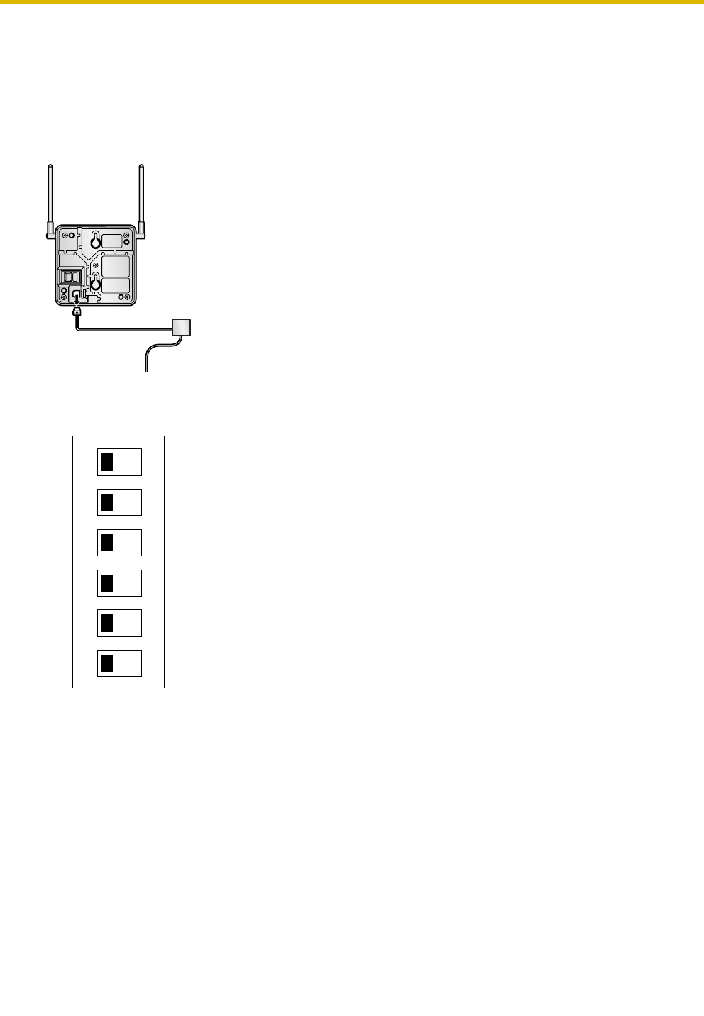
2.9 Connection of 2.4 GHz Portable Stations
Installation Manual 187
2.9.6 After Site Survey
After obtaining the proper measurement results, exit Radio Signal Test mode before connecting the CS to
the Hybrid IP-PBX.
1. Keep pressing the POWER button on the PS until the PS is turned OFF.
2. Disconnect the AC adaptor or battery box from the CS and stop supplying electricity.
3. Switch all DIP switches on the CS from ON to OFF.
1
2
3
4
5
6
OFF ON
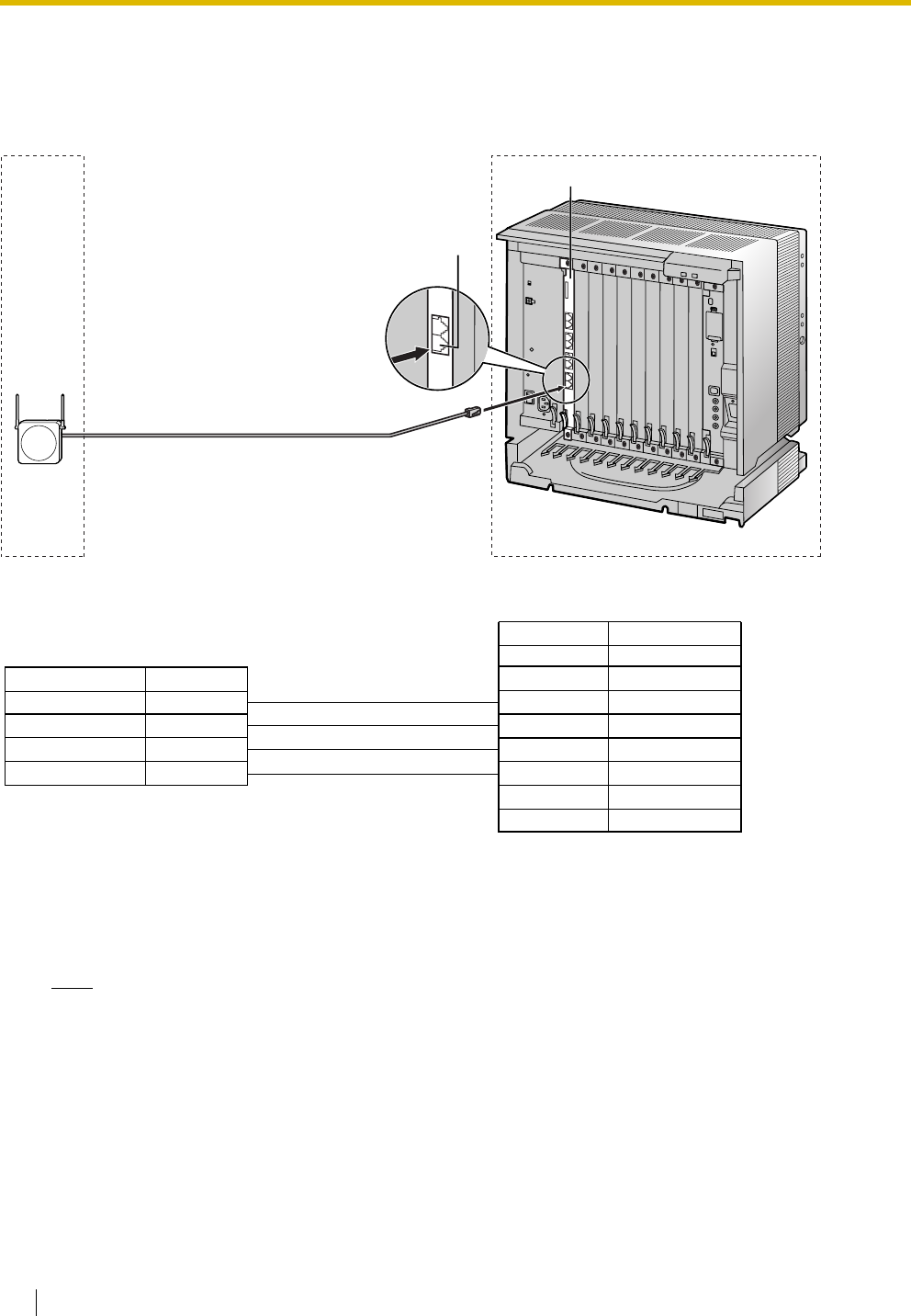
2.9 Connection of 2.4 GHz Portable Stations
188 Installation Manual
2.9.7 Connecting a Cell Station to the Hybrid IP-PBX
Using a CSIF Card
Refer to the following example to connect a CS to the Hybrid IP-PBX.
Accessories and User-supplied Items for the CS
Accessories (included): Screws × 2, Washers × 2
User-supplied (not included): RJ11 connector
Note
For details about CSIF card, refer to "2.5.1 CSIF4 Card (KX-TDA0143) and CSIF8 Card (KX-
TDA0144)".
Signal Name
Signal Name Pin No.
1
2
3
4
D1
POWH
POWL
D2
D1
POWH
POWL
D2
Pin No.
1
2
3
4
5
6
7
8
CSIF card (RJ45)
CS (RJ11)
Cable Maximum Distance
ø 0.4 mm: 444 m
ø 0.5 mm: 694 m
ø 0.6 mm: 1000 m
CAT 5: 694 m
Port 1
CSIF8 Card
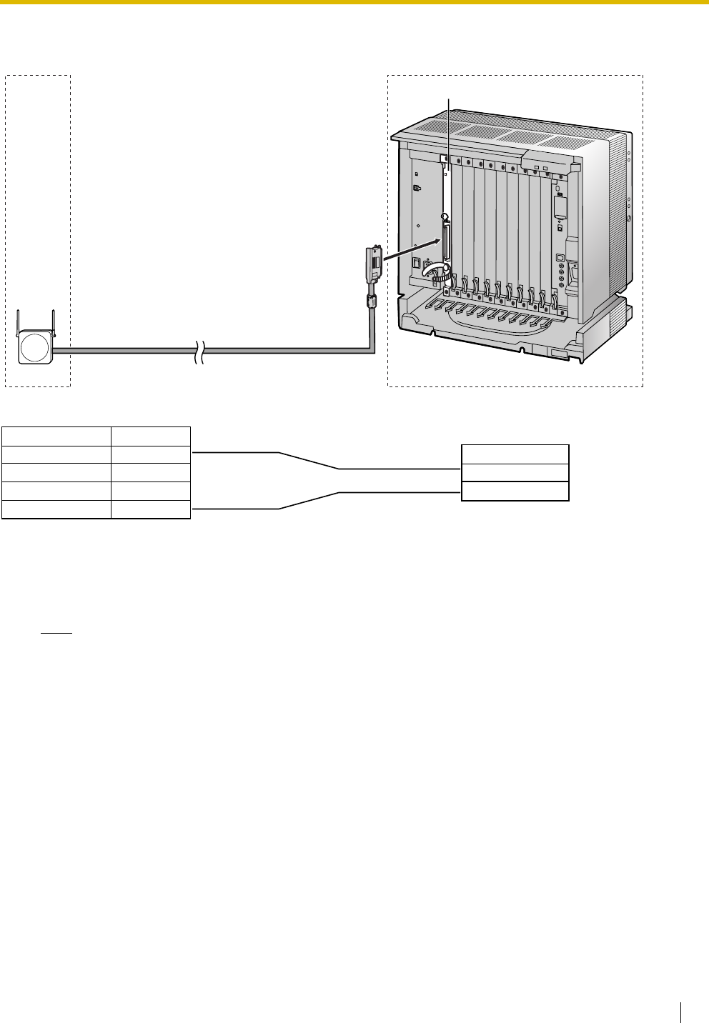
2.9 Connection of 2.4 GHz Portable Stations
Installation Manual 189
Using a DHLC/DLC Card
Refer to the following example to connect a CS to the Hybrid IP-PBX.
Accessories and User-supplied Items for the CS
Accessories (included): Screws × 2, Washers × 2
User-supplied (not included): RJ11 connector
Note
For details about DHLC card or DLC card, refer to "2.5.2 DHLC8 Card (KX-TDA0170)", "2.5.3 DLC8
Card (KX-TDA0171)", or "2.5.4 DLC16 Card (KX-TDA0172)".
Signal Name
D1
D2
DHLC/DLC card
(Amphenol)
Cable Maximum Distance
ø 0.4 mm: 222 m
ø 0.5 mm: 347 m
ø 0.6 mm: 500 m
CAT 5: 347 m
Signal Name Pin No.
1
2
3
4
D1
D2
CS (RJ11)
DHLC8 Card
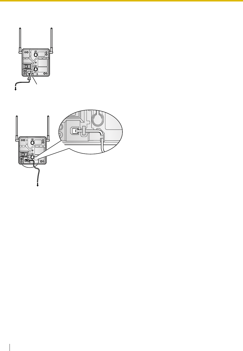
2.9 Connection of 2.4 GHz Portable Stations
190 Installation Manual
Connecting the CS
1. Connect the cable from the CSIF/DHLC/DLC card to the CS.
2. Pass the cable through the groove of the CS (in any direction depending on your preference).
Modular
To CSIF/DHLC/DLC card
To CSIF/DHLC/DLC card
TO MAIN UNIT
/ PABX
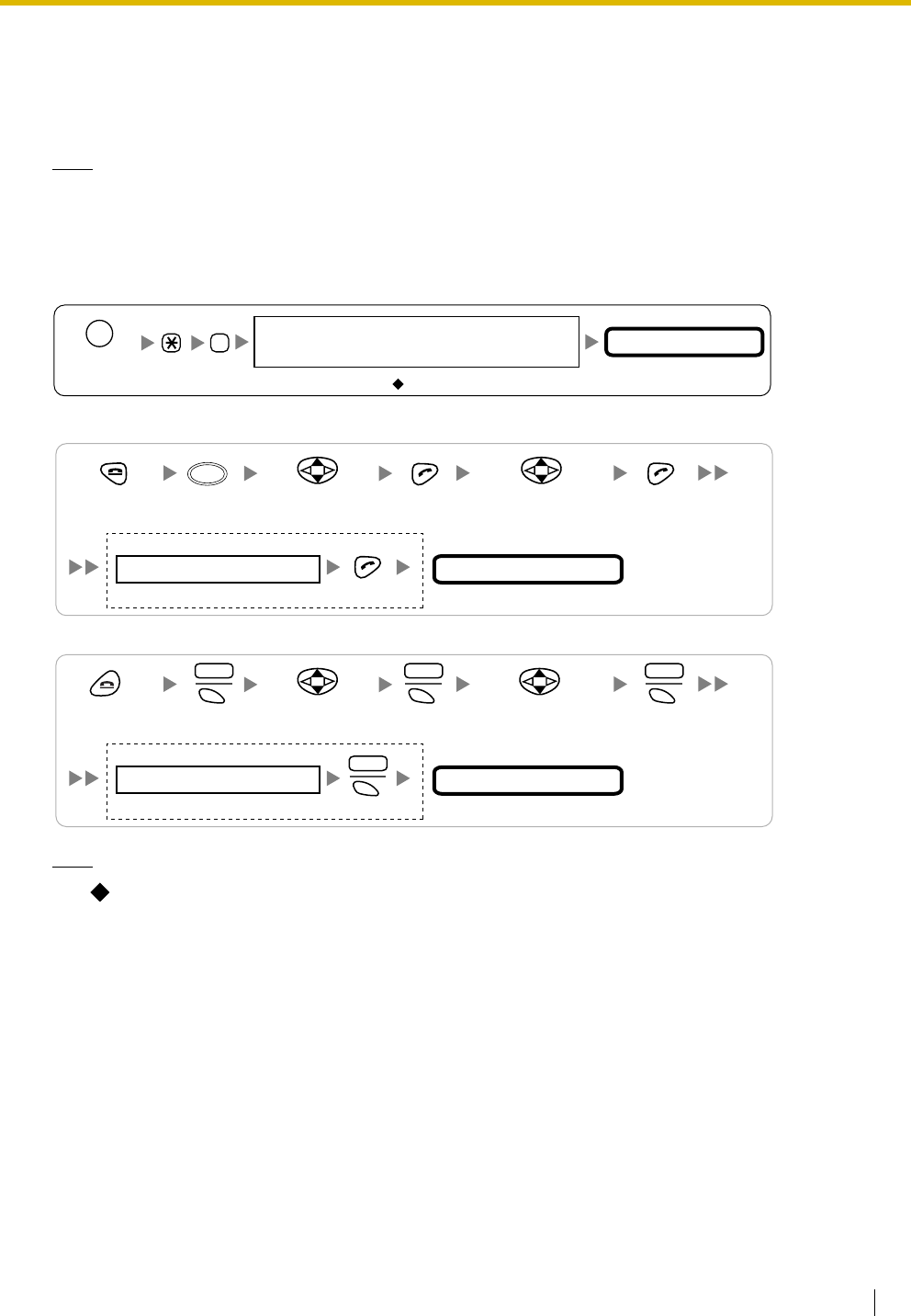
2.9 Connection of 2.4 GHz Portable Stations
Installation Manual 191
Registering the PS
The PS must be registered to the Hybrid IP-PBX before it can be used. Programming of both the PS and
Hybrid IP-PBX is required. A PT with multiline display (e.g., KX-T7636 6-line display) is required to perform
the Hybrid IP-PBX system programming.
Note
For details about system programming using a PT, refer to "2.3.2 PT Programming" in the Feature
Guide, and "2.1 PT Programming" in the PT Programming Manual.
Entering the System Programming Mode
PT (Administrator Level)
PS (Using the KX-TD7680)
PS (Using the KX-TD7690)
Note
means default value throughout this section.
#
= 1234
System Password for Administrator—
for PT Programming Programming No.
3 digits
PROGRAM/
PAUSE
System Setting Menu
Select
"SYSTEM SET".
Press POWER
for 2 seconds.
Select
"PS PROGRAM".
4 digits
System Lock Password
If required
FUNC
System Setting Menu
Select
"SYSTEM SETTING".
Press POWER
for 2 seconds. S1 S1
MENU SEL
S1
SEL
Select
"PS PROGRAM".
4 digits
System Lock Password
If required
ENTR
S1
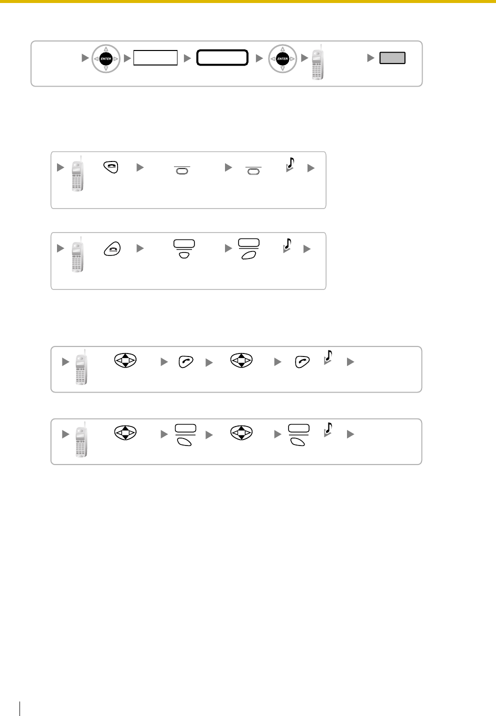
2.9 Connection of 2.4 GHz Portable Stations
192 Installation Manual
PS Registration
When the PS has not been registered yet
When registering the PS for the first time, it is possible to select the desired language for the display.
(You do not need to enter the PS system programming mode when registering for the first time.)
Using the KX-TD7680
Using the KX-TD7690
When the PS has already been registered to another Hybrid IP-PBX
One PS can be registered to a maximum of 4 different Hybrid IP-PBXs.
Using the KX-TD7680
Using the KX-TD7690
[690]
001 to 128
PS No.
1 to 4 digits END
ENTER ENTER
To the PS
operation
below
Extn. No.
Press
POWER for
2 seconds.
Press S3
for 2
seconds.
C.Tone
Press S2 repeatedly
to select the desired
language.
[
F2
][
F3
]
Press
POWER for
2 seconds.
Press S3
for 2
seconds.
C.Tone
Press S2 repeatedly
to select the desired
language.
F2 F3
Choose
"SYSTEM 1–4".
Select
"REGISTRATION".
C.Tone
Choose
"SYSTEM 1–4".
Select
"REGISTRATION".
S1S1
SEL SEL
C.Tone
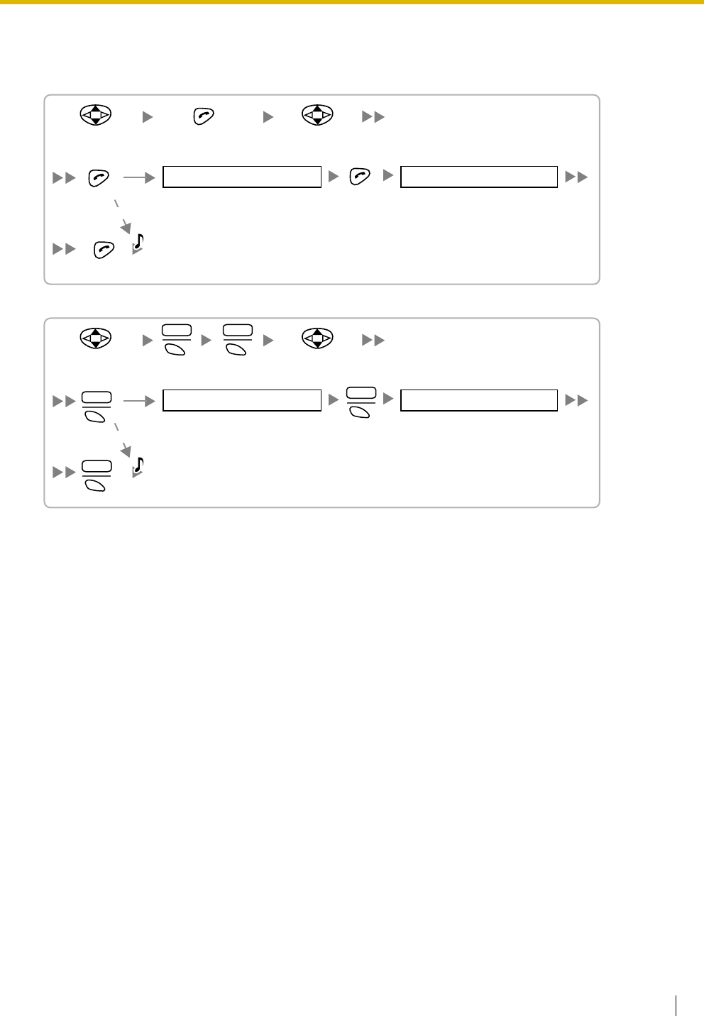
2.9 Connection of 2.4 GHz Portable Stations
Installation Manual 193
Setting the System Lock
When a system lock has been set, the system lock password will be required for PS system setting.
Using the KX-TD7680
Using the KX-TD7690
Choose
"Enable/Disable".
Select
"SYSTEM LOCK".
C.Tone
4 digits 4 digits
ENABLE
DISABLE
System Lock Password System Lock Password
S1 Choose
"Enable/Disable".
SEL
ENTR
S1
S1
S1
S1
CHNG
SEL
ENTR
Select
"SYSTEM LOCK".
C.Tone
System Lock Password System Lock Password
4 digits 4 digits
ENABLE
DISABLE
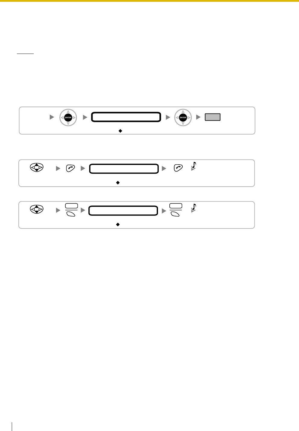
2.9 Connection of 2.4 GHz Portable Stations
194 Installation Manual
Setting the Personal Identification Number (PIN) for PS Registration
To prevent registering the PS to a wrong Hybrid IP-PBX, a PIN for PS registration can be set to the Hybrid
IP-PBX. Before registering the PS to the Hybrid IP-PBX, enter the PIN set to the Hybrid IP-PBX into the PS.
By doing so, the PS will only be registered to the Hybrid IP-PBX with the matching PIN.
Notes
• By default, the PIN for PS registration is "1234" for both the Hybrid IP-PBX and PS. Therefore, the
PS can be registered to the Hybrid IP-PBX without setting the PIN.
• The PIN for PS registration will only be used when registering the PS to the Hybrid IP-PBX.
Therefore, during normal operation after registration, even if there is more than 1 Hybrid IP-PBX
with the same PIN near the PS, the PS will not be inadvertently linked to a different Hybrid IP-PBX.
Setting the PIN for Hybrid IP-PBX
Setting the PIN for PS
Using the KX-TD7680
Using the KX-TD7690
[692]
4 digits
PIN for PS Registration
END
ENTER ENTER
1234
Select
"CHANGE PIN"
C.Tone
1 to 4 digits
1234
PIN for PS Registration
Select
"CHANGE PIN"
S1
ENTR
S1
SEL
C.Tone
1 to 4 digits
1234
PIN for PS Registration
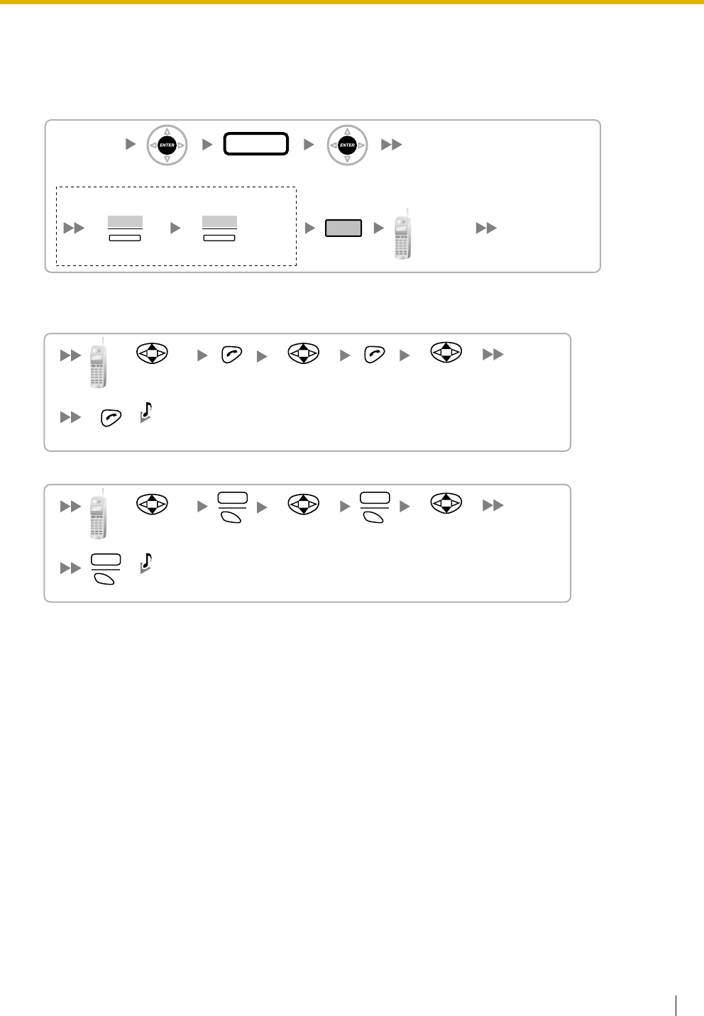
2.9 Connection of 2.4 GHz Portable Stations
Installation Manual 195
PS Termination
Confirm the following before cancelling the PS registration:
• The PS is turned on.
• The PS is within range.
If the registration information is still stored in the PS
Using the KX-TD7680
Using the KX-TD7690
Testing the Operation
Walk around the service area while having a conversation using a registered PS. If noise is frequent or
conversations disconnect, relocate the CSs or install an additional CS.
[691]
001 to 128
PS No.
ENTER ENTER
END
To the PS
operation
below
If "Rejected" or "Time out" is displayed
CLEAR YES
Press "YES".Press "CLEAR".
Select the
desired item.
Select "DELETE
SYSTEM".
Select "YES".
C.Tone
Select the
desired item.
Select "DELETE
SYSTEM".
S1S1
SEL SEL
Select "YES".
C.Tone
S1
SEL
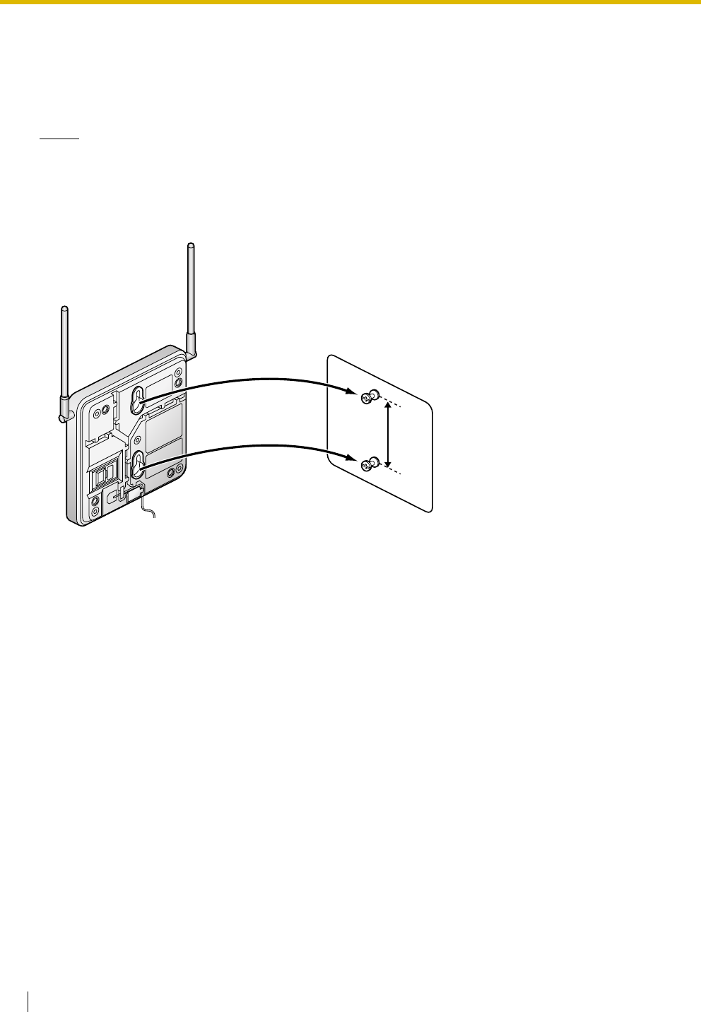
2.9 Connection of 2.4 GHz Portable Stations
196 Installation Manual
2.9.8 Wall Mounting
1. Place the reference for wall mounting (on the following page) on the wall to mark the 2 screw positions.
2. Install the 2 screws and washers (included) into the wall.
Notes
• Make sure that the screw heads are at the same distance from the wall.
• Install the screws perpendicular to the wall.
3. Hook the CS on the screw heads.
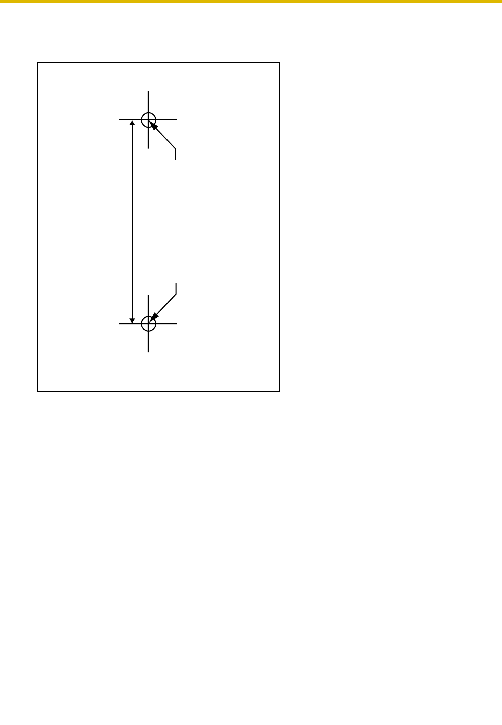
2.9 Connection of 2.4 GHz Portable Stations
Installation Manual 197
Reference for Wall Mounting
Please copy this page and use as a reference for wall mounting.
Note
Make sure to set the print size to correspond with the size of this page. If the dimension of the paper
output still deviates slightly from the measurement indicated here, use the measurement indicated
here.
Install a screw here.
Install a screw here.
71 mm
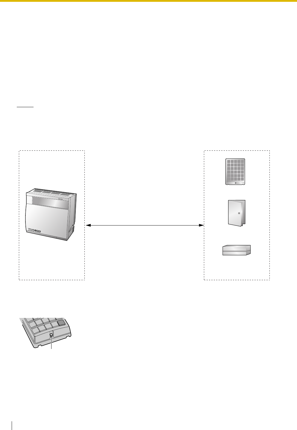
2.10 Connection of Doorphones, Door Openers, External Sensors, and External Relays
198 Installation Manual
2.10 Connection of Doorphones, Door Openers,
External Sensors, and External Relays
2.10.1 Connection of Doorphones, Door Openers, External
Sensors, and External Relays
The Hybrid IP-PBX supports a maximum of 16 doorphones (KX-T30865 with a DPH4 card, or German-type
doorphone with a DPH2 card), 16 door openers, 16 external sensors, and 16 external relays.
Notes
• KX-T30865 is a Panasonic doorphone.
• German-type doorphones, door openers, external sensors, and external relays are user-supplied.
Maximum Cabling Distance
Installing the Doorphone (KX-T30865)
1. Loosen the screw to separate the doorphone into 2 halves.
Cable Maximum Distance
ø 0.4 mm: 70 m
ø 0.5 mm: 113 m
ø 0.6 mm: 180 m
CAT 5: 113 m
Doorphone
Door Opener
External Sensor/
External Relay Device
Panasonic
Screw
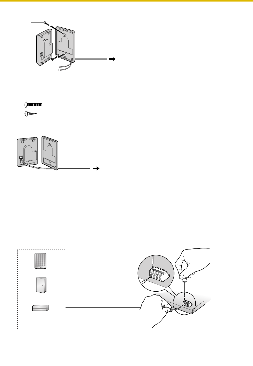
2.10 Connection of Doorphones, Door Openers, External Sensors, and External Relays
Installation Manual 199
2. Pass the wires through the hole in the base cover, and attach the base cover to a wall using 2 screws.
Note
Two kinds of screws are included with a KX-T30865. Please choose the appropriate kind for your wall
type.
3. Connect the wires to the screws located in the front cover.
4. Re-attach the 2 halves and re-insert the screw.
Connection
Use 8-pin and 10-pin terminal blocks (included with the card) for connection.
1. While pressing down on the hole at the top of the terminal block using a screwdriver, insert the wire into
the side hole as shown below. Repeat this procedure for other doorphones, door openers, external
sensors, and external relays.
Refer to "2.6.2 DPH4 Card (KX-TDA0161)", "2.6.3 DPH2 Card (KX-TDA0162)", and "2.6.4 EIO4 Card
(KX-TDA0164)" for pin assignments.
: when a doorphone plate has been fixed to the wall
: when you wish to install the doorphone directly onto the wall
Screw
To 8-pin terminal block
To 8-pin terminal block
Doorphone
Door Opener
External Sensor/
External Relay Device
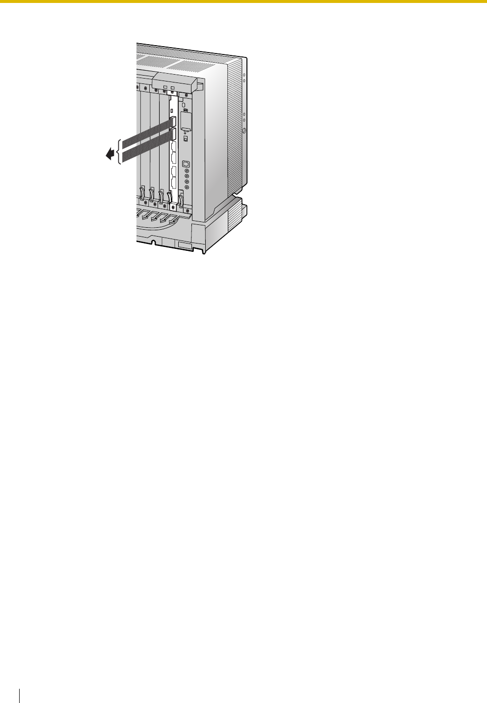
2.10 Connection of Doorphones, Door Openers, External Sensors, and External Relays
200 Installation Manual
2. Attach the terminal blocks to the connectors of the DPH4/DPH2/EIO4 card on the Hybrid IP-PBX.
To doorphones/
door openers/
external sensors/
external relays
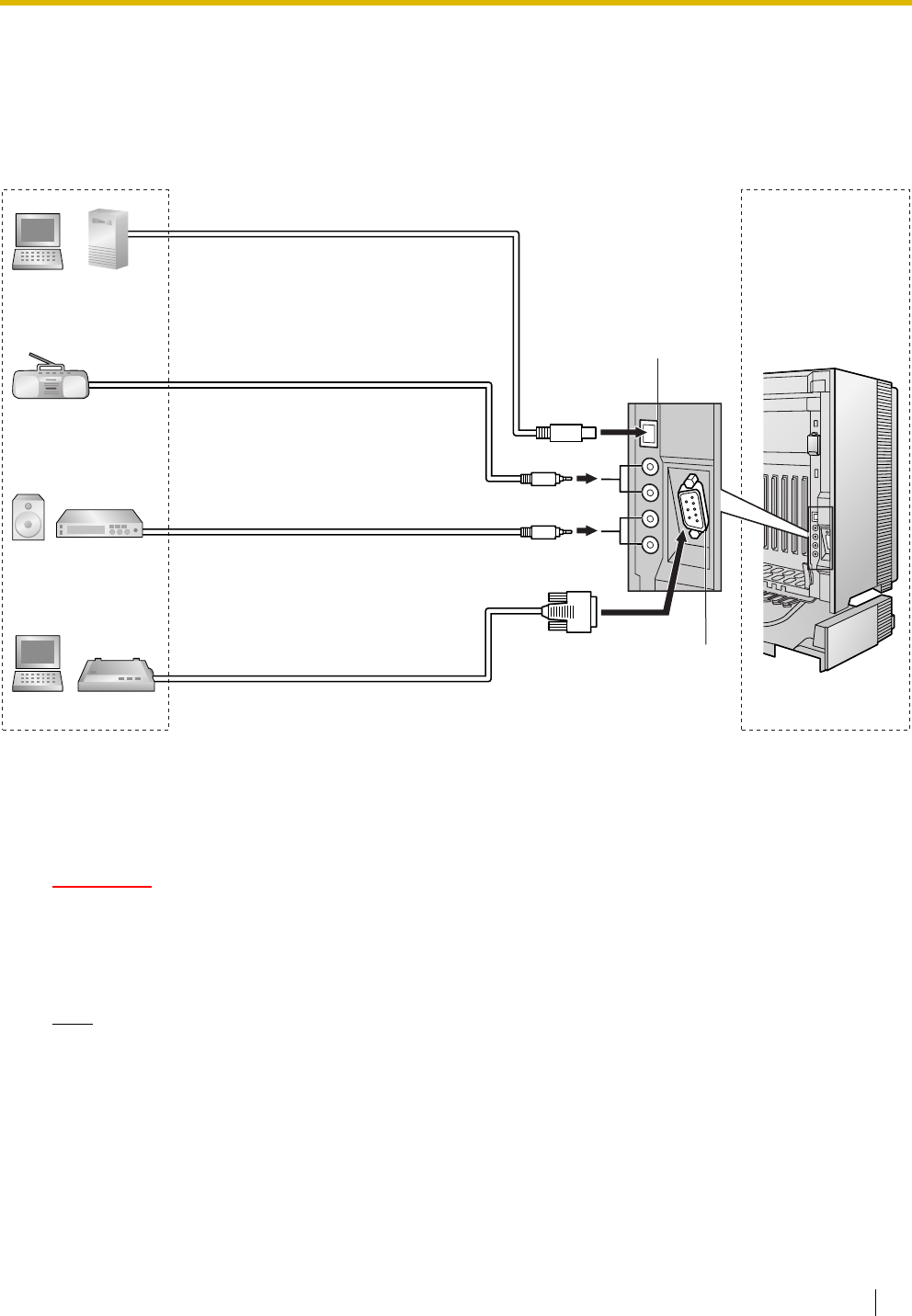
2.11 Connection of Peripherals
Installation Manual 201
2.11 Connection of Peripherals
2.11.1 Connection of Peripherals
BGM/MOH
The Hybrid IP-PBX provides Background Music and Music on Hold. Up to 2 external music sources (e.g.,
user-supplied radios) can be connected to the Hybrid IP-PBX.
CAUTION
• Wiring should be done carefully to prevent undue force being exerted on the plug. Otherwise,
sound may only be heard intermittently.
• External Music Jacks are SELV ports and should only be connected to approved SELV devices, or
in Australia, via the Line Isolation Unit with the Telecommunications Compliance Label.
Note
When the Hybrid IP-PBX and external music sources are not connected to the same earth, hum noise
may be induced into Background Music and Music on Hold.
BGM/
Music on Hold
Pager:
Amplifier/Speaker
PC Printer
PC Cable Maximum Distance
ø 0.4 mm: 10 m
ø 0.5 mm: 10 m
ø 0.6 mm: 10 m
CAT 5: 10 m
Cable Maximum Distance
ø 0.4 mm: 10 m
ø 0.5 mm: 10 m
ø 0.6 mm: 10 m
CAT 5: 10 m
Maximum Distance
5 m
Maximum Distance
2 m
USB
RS-232C
CTI Server
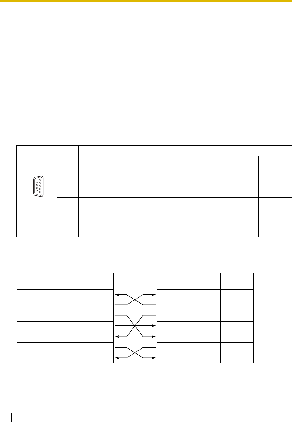
2.11 Connection of Peripherals
202 Installation Manual
Pager
Up to 2 paging devices (user-supplied) can be connected to the Hybrid IP-PBX.
CAUTION
External Paging Jacks are SELV ports and should only be connected to approved SELV devices, or in
Australia, via the Line Isolation Unit with the Telecommunications Compliance Label.
PC/Printer (via RS-232C)
The Hybrid IP-PBX is equipped with an RS-232C interface. This interface provides communication between
the Hybrid IP-PBX and the user-supplied devices such as PC or line printers. The RS-232C port is used for
system programming, SMDR, diagnostics and external system database storage (save/load) functions.
Note
Use an RS-232C cross cable for connection between the Hybrid IP-PBX and PC.
Pin Assignments
Connection Charts
For connecting a printer/PC with a 9-pin RS-232C connector
No. Signal Name Function Circuit Type
EIA CCITT
2 RD (RXD) Receive Data BB 104
3
4
SD (TXD)
ER (DTR)
Transmit Data
Data Terminal Ready
BA
CD
103
108.2
5
6
SG
DR (DSR)
Signal Ground
Data Set Ready
AB
CC
102
107
7
8
RS (RTS)
CS (CTS)
Request To Send
Clear To Send
CA
CB
105
106
9 5
6 1
Hybrid IP-PBX Printer/PC
Circuit Type
(EIA)
Signal
Name Pin No. Pin No. Signal
Name
Circuit Type
(EIA)
BB RD (RXD) 2
BA SD (TXD) 3
CD ER (DTR) 4
AB SG 5
CC DR (DSR) 6
CA RS (RTS) 7
CB CS (CTS) 8
2 RD (RXD) BB
3 SD (TXD) BA
4 ER (DTR) CD
5SG AB
6 DR (DSR) CC
7 RS (RTS) CA
8 CS (CTS) CB
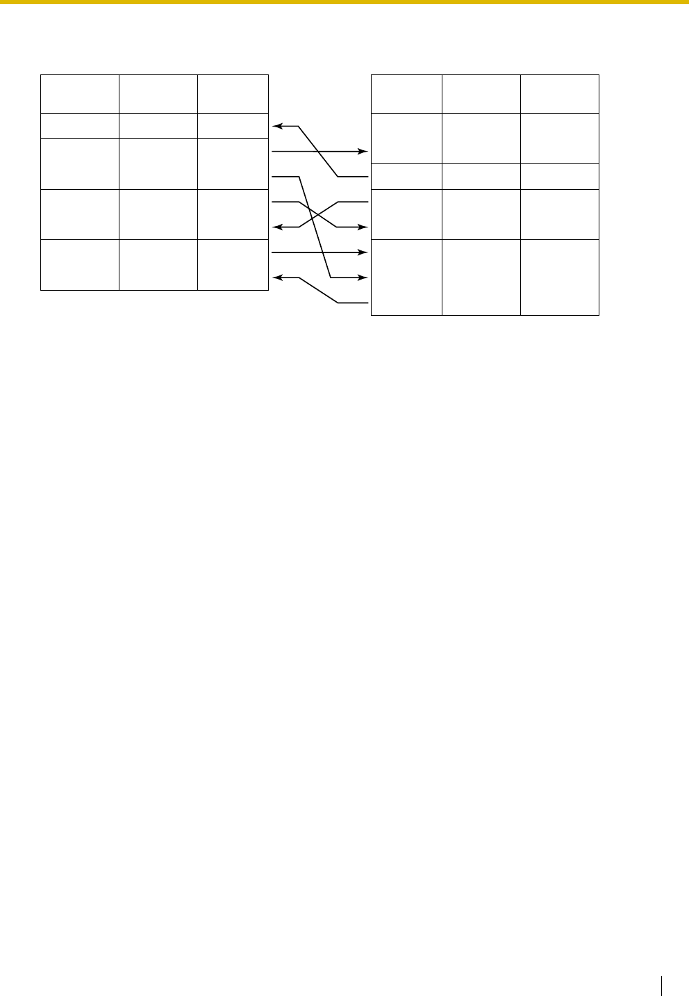
2.11 Connection of Peripherals
Installation Manual 203
For connecting a printer/PC with a 25-pin RS-232C connector
RS-232C Signals
•Receive Data (RXD):…(input)
Conveys signals from the printer or the PC.
•Transmit Data (TXD):…(output)
Conveys signals from the unit to the printer or the PC. A "Mark" condition is held unless data or
BREAK signals are being transmitted.
•Data Terminal Ready (DTR):…(output)
This signal line is turned ON by the unit to indicate that it is ON LINE. Circuit ER (DTR) ON does
not indicate that communication has been established with the printer or the PC. It is switched OFF
when the unit is OFF LINE.
•Signal Ground (SG)
Connects to the DC ground of the unit for all interface signals.
•Data Set Ready (DSR):…(input)
An ON condition of circuit DR (DSR) indicates the printer or the PC is ready. Circuit DR (DSR) ON
does not indicate that communication has been established with the printer or the PC.
•Request To Send (RTS):…(output)
This lead is held ON whenever DR (DSR) is ON.
•Clear To Send (CTS):…(input)
An ON condition of circuit CS (CTS) indicates that the printer or the PC is ready to receive data
from the unit. The unit does not attempt to transfer data or receive data when circuit CS (CTS) is
OFF.
•Frame Ground (FG)
Connects to the unit frame and the earth ground conductor of the AC power cord.
Hybrid IP-PBX Printer/PC
Circuit Type
(EIA)
Signal
Name Pin No. Signal
Name
Circuit Type
(EIA)
BB RD (RXD) 2
BA SD (TXD) 3
CD ER (DTR) 4
AB SG 5
CC DR (DSR) 6
CA RS (RTS) 7
CB CS (CTS) 8
1FG AA
3 RD (RXD) BB
2 SD (TXD) BA
20 ER (DTR) CD
7SG AB
5 CS (CTS) CB
6 DR (DSR) CC
CF
4 RS (RTS)
Pin No.
2.11 Connection of Peripherals
204 Installation Manual
PC/CTI Server (via USB version 2.0)
The Hybrid IP-PBX is equipped with a USB interface. This interface provides communication between the
Hybrid IP-PBX and a PC or a CTI server.
The PC is used for system programming, diagnostics and external system database storage (save/load)
functions.
The CTI server is used for connecting PCs on a LAN to provide third party call control CTI. The CTI
connection uses the CSTA Phase 3 or TAPI 2.1 protocol.
Note
The operating system of the PC or CTI server required for third party call control depends on your CTI
application software. For details, refer to the manual for your CTI application software.
Pin Assignments
No. Signal Name
1VBUS
2USB D-
3USB D+
4GND
2
1
3
4
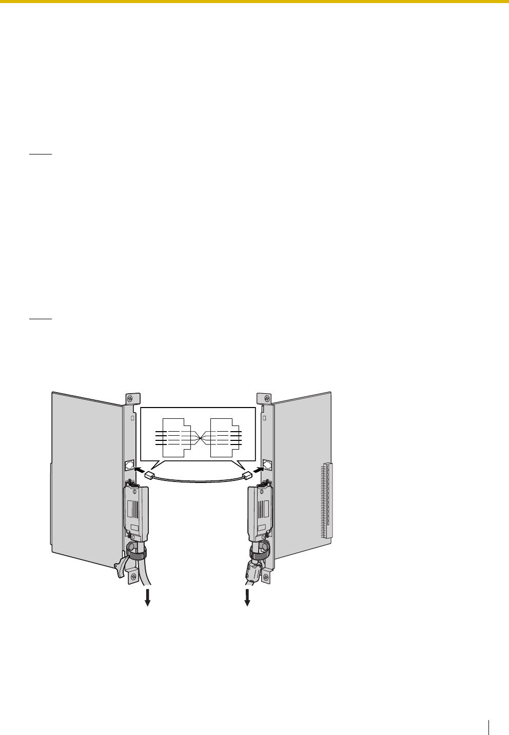
2.12 Power Failure Connections
Installation Manual 205
2.12 Power Failure Connections
2.12.1 Power Failure Connections
When the power supply to the Hybrid IP-PBX fails, power failure transfer (PFT) will switch from the current
connection to the Power Failure Connection. Refer to "2.4.1 Power Failure Transfer" in the Feature Guide
for further information.
Note
While DC power is provided by the backup batteries, the Hybrid IP-PBX will remain fully operational and
the connection will not switch to the Power Failure Connection.
Using Analogue Trunk Card and Extension Card
Power Failure Connection connects a specific SLT and a trunk in the event of power failure. The following
analogue trunk and extension cards can be used for Power Failure Connections:
•Analogue trunk cards: LCOT16 (4 PFT ports), LCOT8 (2 PFT port), and LCOT4 (2 PFT port)
•Extension cards: MSLC16 (4 PFT ports), SLC16 (4 PFT ports), DHLC8 (2 PFT port) and SLC8
(2 PFT port)
To 1 analogue trunk card, connect only 1 extension card.
Note
By programming the Hybrid IP-PBX, a trunk conversation established during power failure can be
maintained even when the power returns and the connection is switched back to the normal
configuration from the Power Failure Connection. However, if no special programming is performed, the
connection will be dropped when power returns.
Accessories and User-supplied Items
Accessories (included): none
User-supplied (not included): RJ11 connectors
Trunk Card
(e.g., LCOT8)
Extension Card
(e.g., SLC8)
R2
R1
T1
T2
T2
T1
R1
R2
RJ11
To trunk To S LT
2.12 Power Failure Connections
206 Installation Manual
RJ11 Connector Pin Assignments for Analogue Trunk Card
PFT Ports 1 and 2
PFT Ports 3 and 4 (for LCOT16 card only)
RJ11 Connector Pin Assignments for Extension Card
PFT Ports 1 and 2
PFT Ports 3 and 4 (for MSLC16/SLC16 card only)
No. Signal Name Function
1 R2 Ring port 2
2 R1 Ring port 1
3 T1 Tip port 1
4 T2 Tip port 2
No. Signal Name Function
1 R4 Ring port 4
2 R3 Ring port 3
3 T3 Tip port 3
4 T4 Tip port 4
No. Signal Name Function
1 T2 Tip port 2
2 T1 Tip port 1
3 R1 Ring port 1
4 R2 Ring port 2
No. Signal Name Function
1 T4 Tip port 4
2 T3 Tip port 3
3 R3 Ring port 3
4 R4 Ring port 4
1
4
1
4
1
4
1
4
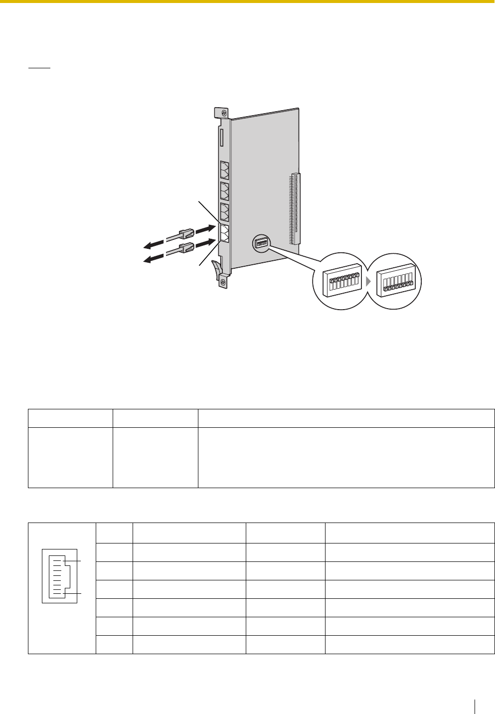
2.12 Power Failure Connections
Installation Manual 207
Using BRI Card
LINE 1 and LINE 2 of the BRI4 and BRI8 cards can be used for Power Failure Connections.
Note
When the power returns, the connection will switch back to normal configuration from the Power Failure
Connection, and a trunk conversation established during power failure will be dropped.
Accessories and User-supplied Items
Accessories (included): none
User-supplied (not included): RJ45 connectors
Switch Settings
RJ45 Connector LINE 1 Pin Assignments
Switch Type Usage and Status Definition
PFT Setting DIP Set all DIP switches to "ON" positions to use LINE 1 and LINE 2 as
a PFT port.
LINE 1: Power Failure LINE (NT1)
LINE 2: Power Failure EXTN (extension)
No. Signal Name Level [V] Function
1-2 Reserved – –
3 TX1 (+) Transmit data 1
4 RX2 (+) Receive data 2
5 RX1 (-) Receive data 1
6 TX2 (-) Transmit data 2
7-8 Reserved – –
RJ45
(LINE 2)
RJ45
(LINE 1)
To N T 1
OFF
ON
OFF
ON
To ISDN extension
Set all DIP switches
at "ON" positions.
8
1

2.12 Power Failure Connections
208 Installation Manual
RJ45 Connector LINE 2 Pin Assignments
No. Signal Name Level [V] Function
1-2 Reserved – –
3 RX2 (+) Receive data 2
4 TX1 (+) Transmit data 1
5 TX2 (-) Transmit data 2
6 RX1 (-) Receive data 1
7-8 Reserved – –
8
1
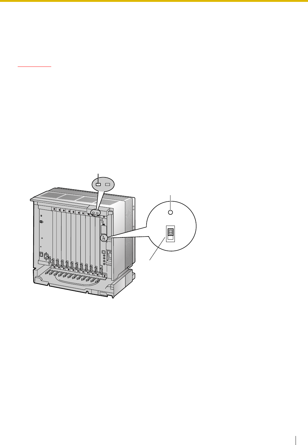
2.13 Starting the Hybrid IP-PBX
Installation Manual 209
2.13 Starting the Hybrid IP-PBX
2.13.1 Starting the Hybrid IP-PBX
CAUTION
• SD Memory Card must be inserted in the SD Memory Card slot of the MPR card before start up.
• Before touching the System Initialise Switch, discharge static electricity by touching ground or
wearing an earthing strap.
• Once you have started the Hybrid IP-PBX and if you unplug the Hybrid IP-PBX, do not perform the
following procedures to start the Hybrid IP-PBX again. Otherwise, your programmed data is
cleared. To restart the Hybrid IP-PBX, refer to "4.1.4 Using the Reset Button".
• The Hybrid IP-PBX will continue to be powered even if the power switch is turned "OFF".
• The power supply cord is used as the main disconnect device. Ensure that the AC outlet is located
near the equipment and is easily accessible.
1. Slide the System Initialise Switch to the "SYSTEM INITIALIZE" position.
System Initialise Switch
Reset Button
SYSTEM
INITIALIZE
RESET
NORMAL
RUN Indicator
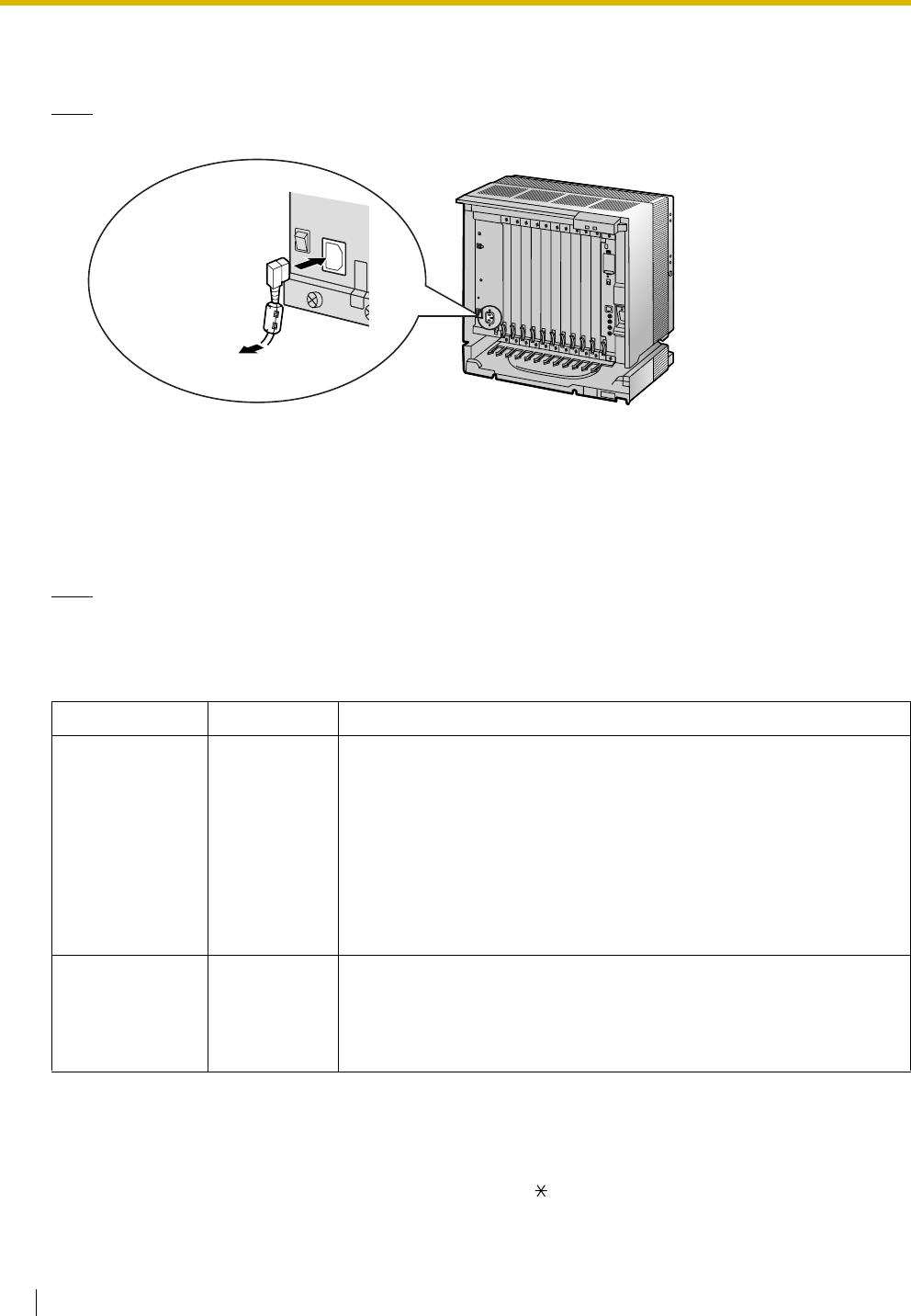
2.13 Starting the Hybrid IP-PBX
210 Installation Manual
2. Plug the AC power cord into the Hybrid IP-PBX and an AC outlet, and turn on the Hybrid IP-PBX. The
RUN indicator will flash.
Note
For safety reasons, do not stretch, bend, or pinch the AC power cord.
3. While the RUN indicator is flashing, slide the System Initialise Switch back to the "NORMAL" position.
Depending on the configuration, initialisation takes about 1 min to 3 min. If successfully executed, the
RUN indicator will stop flashing and stay lit.
All data will be cleared, and the Hybrid IP-PBX as well as all optional service cards (except for the IP-GW
card) will be initialised to the default values. The DPTs should show the time as 01:00.
The data of the IP-GW card will not be initialised.
Note
Use only the AC power cord included with the Hybrid IP-PBX for the PSU.
LED Indications
Confirming the Trunk Connection
After initialisation, programme the Hybrid IP-PBX and connect trunks to the Hybrid IP-PBX.
To confirm that the trunks are successfully connected, dial [ ] [3] [7] + trunk number (3 digits) on a PT, or
press the PT's S-CO button. You will hear a dial tone if the trunk is available and connected.
Indication Colour Description
RUN Green PBX status indication
• OFF: Power Off (includes normal reset)
• ON: Power On and running (on-line)
• Flashing (60 times per minute): Starting up
• Flashing (120 times per minute): Starting up or resetting with:
• the System Initialise Switch in "SYSTEM INITIALIZE"
position
• the SD Memory Card not inserted
ALARM Red Alarm indication
• OFF: Normal
• ON: Alarm (CPU stop, alarm for each optional service card)
• Flashing: Alarm (MPR file error in restarting)
To AC Outlet

Installation Manual 211
Section 3
Guide for the KX-TDA Maintenance Console
Explains the installation procedure, structure, and basic
information of the KX-TDA Maintenance Console.

3.1 Overview
212 Installation Manual
3.1 Overview
3.1.1 Overview
KX-TDA Maintenance Console is designed to serve as an overall system programming reference for the
Hybrid IP-PBX. To programme and administer the Hybrid IP-PBX by PC, you need to install the KX-TDA
Maintenance Console onto the PC.
This section describes overview and installation of the KX-TDA Maintenance Console only.
KX-TDA Maintenance Console*1
*1 The contents and design of the software are subject to change without notice.
Menu Bar
Programme Menu
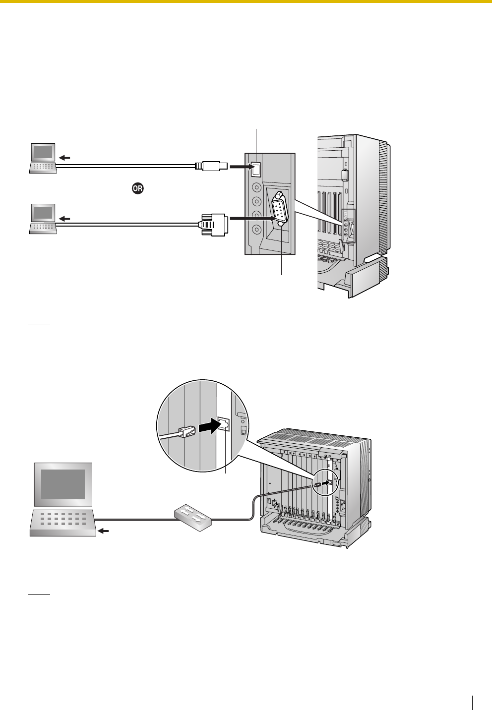
3.2 Connection
Installation Manual 213
3.2 Connection
3.2.1 Connection
Serial Interface Connection
Note
For pin assignments and maximum cabling distance, refer to "2.11.1 Connection of Peripherals".
LAN Connection via CTI-LINK Card
Note
For pin assignments and maximum cabling distance, refer to "2.6.7 CTI-LINK Card (KX-TDA0410)".
PC
USB Port
To USB Port
To COM Port
RS-232C Port
PC
PC
Switching Hub
To network port
RJ45
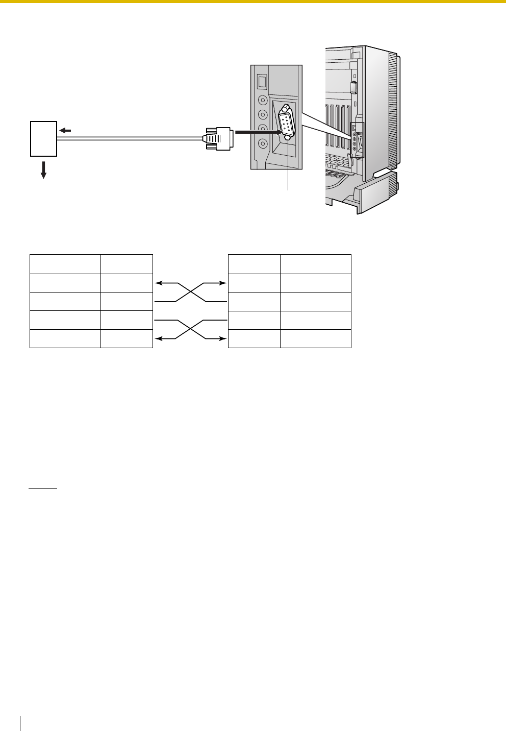
3.2 Connection
214 Installation Manual
External Modem Connection
After connecting the Hybrid IP-PBX and the external modem, set the power switch of the external modem
to "ON", then the external modem will be initialised with the default values.
The following AT command settings may be required for the modem:
• The Data Terminal Ready (DTR) signal should be ignored.
• The Data Terminal Equipment (DTE)/Modem flow control should be turned off.
• Data compression should be disabled.
• Error Correction is not necessary.
Notes
• Use an RS-232C straight cable for connection between the Hybrid IP-PBX and external modem.
• An AT command (for initialisation, enabling automatic answer, etc.) can only be programmed by
KX-TDA Maintenance Console. "AT&F0Q0E0V1S0=1X0&D0" is stored as the default value.
• For more information about the AT command, refer to the external modem's instructions.
To RS-232C port (25-pin)
RS-232C Port
(9-pin)
To trunk/Hybrid IP-PBX extension
port assigned as the trunk destination
Modem
External Modem Hybrid IP-PBX
Signal Name Pin No. Signal Name
SD (TXD) 2
RD (RXD) 3
DR (DSR) 6
ER (DTR) 20
2 RD (RXD)
3 SD (TXD)
4 ER (DTR)
6 DR (DSR)
Pin No.

3.3 Installation of the KX-TDA Maintenance Console
Installation Manual 215
3.3 Installation of the KX-TDA Maintenance
Console
3.3.1 Installing and Starting the KX-TDA Maintenance Console
System Requirements
Required Operating System
• Microsoft Windows 98 SE, Windows Me, Windows 2000, or Windows XP
Minimum Hardware Requirements
• CPU: 300 MHz Intel Celeron microprocessor
• HDD: 100 MB of available hard disk space
• RAM: 128 MB of available RAM
Password Security
Warning to the Administrator or Installer regarding the system password
1. Please provide all system passwords to the customer.
2. To avoid unauthorised access and possible abuse of the Hybrid IP-PBX, keep the passwords
secret, and inform the customer of the importance of the passwords, and the possible dangers if
they become known to others.
3. The Hybrid IP-PBX has default passwords preset. For security, change these passwords the first
time that you programme the Hybrid IP-PBX.
4. Change the passwords periodically.
5. It is strongly recommended that passwords of 10 numbers or characters be used for maximum
protection against unauthorised access. For a list of numbers and characters that can be used in
system passwords, refer to "1.1.3 Entering Characters" in the PT Programming Manual.
6. If a system password is forgotten, it can be found by loading a backup of the system data into a
PC, and checking the password using the KX-TDA Maintenance Console software. If you do not
have a backup of the system data, you must reset the Hybrid IP-PBX to its factory defaults and
reprogramme it. Therefore, we strongly recommend maintaining a backup of the system data. For
more information on how to back up the system data, refer to the on-line help of the Maintenance
Console.
However, as system passwords can be extracted from backup copies of the system data file, do
not allow unauthorised access to these files.
®®
®®

3.3 Installation of the KX-TDA Maintenance Console
216 Installation Manual
Installing the KX-TDA Maintenance Console
Notes
• Make sure to install and use the latest version of the KX-TDA Maintenance Console.
• To install or uninstall the software on a PC running Windows 2000 Professional or Windows XP
Professional, you must be logged in as a user in either the "Administrators" or "Power Users" group.
• To connect the PC to the Hybrid IP-PBX via USB, the KX-TDA USB driver must be installed. Follow
the instructions of the wizard to install the KX-TDA USB driver. When the Hybrid IP-PBX is first
connected to the PC via USB, you may be asked to select the appropriate USB driver. Browse for
and select the KX-TDA USB driver that was installed previously.
Starting the KX-TDA Maintenance Console and Assigning the Basic
Items (Quick Setup)
When you start the KX-TDA Maintenance Console with the Installer Level Programmer Code and connect
to the Hybrid IP-PBX for the first time after initialisation (with the factory default setting), Quick Setup will
launch automatically. During Quick Setup, you will set up the basic items. For details about the basic items,
refer to "2.3.4 Quick Setup" in the Feature Guide.
1. Copy the setup file of the KX-TDA Maintenance Console to
your PC. (Its icon is shown here, on the left.)
2. Double-click the setup file to run the installer.
3. Follow the on-screen instructions provided by the
installation wizard.
1. Connect the PC to the Hybrid IP-PBX with a USB cable.
2. Start the KX-TDA Maintenance Console from the Start
menu.
3. "Information Before Programming" appears.
a. Carefully read this important additional information,
which includes updates to this and other manuals.
b. Click [OK] to close this window.
4. Enter the Installer Level Programmer Code (default:
INSTALLER), then click [OK].
The Programmer Code authorises different programming
levels, and the Quick Setup is only available when you start
the KX-TDA Maintenance Console with the Installer Level
Programmer Code.
Note
There are 2 other Programmer Codes with limited
authorisation: Administrator Level (default: ADMIN),
and User Level (default: USER).
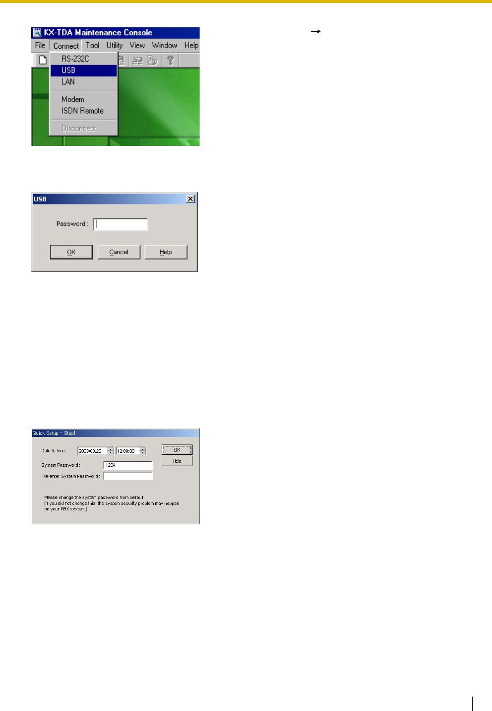
3.3 Installation of the KX-TDA Maintenance Console
Installation Manual 217
5. Click "Connect" "USB" from the menu bar.
6. Enter the system password for installer (default: 1234),
then click [OK] to log-in.
7. When country/area data do not match:
a. Click [OK] to replace the country/area data of the
Hybrid IP-PBX. Replacement may take several
minutes to complete.
b. Follow the procedure described in "2.13.1 Starting the
Hybrid IP-PBX" and restart the Hybrid IP-PBX.
c. Repeat steps 5 to 6 to restart the KX-TDA Maintenace
Console.
8. Follow the instructions of the wizard and assign the basic
items (Quick Setup).
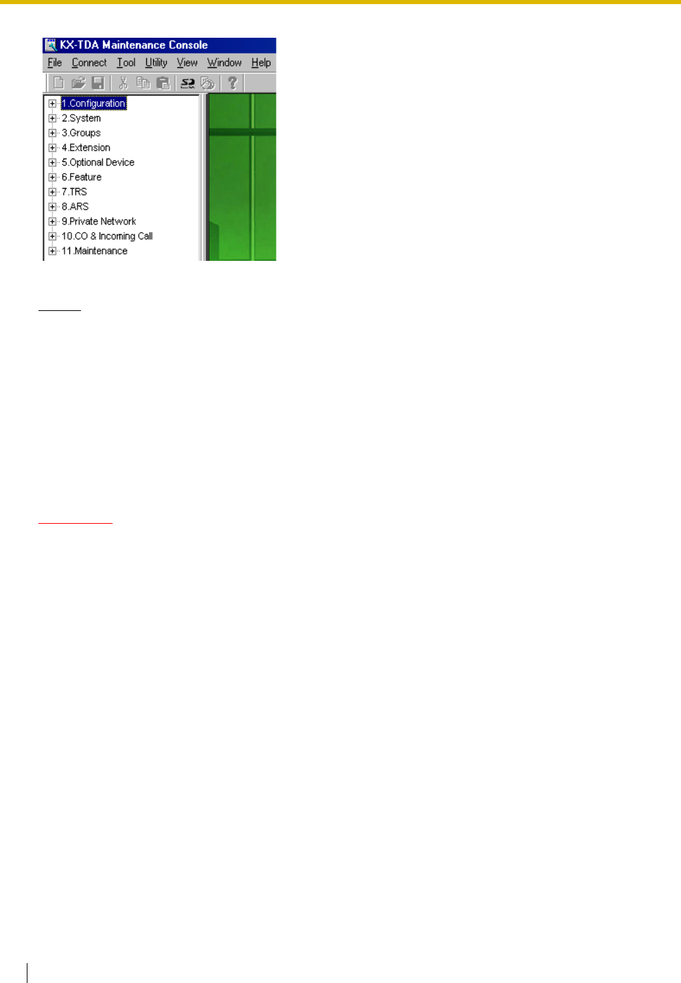
3.3 Installation of the KX-TDA Maintenance Console
218 Installation Manual
Notice
1. During a long programming session, it is highly recommended that you periodically save the
system data to the SD Memory Card. If the Hybrid IP-PBX undergoes a sudden power failure or if
the system is reset for some reason, all the system data in RAM will be lost. However, if system
data has been saved to the SD Memory Card, it can be easily restored.
To save the system data to the SD Memory Card, (1) click the "SD Memory Backup" icon before
resetting the Hybrid IP-PBX or turning off the power, or (2) exit the KX-TDA Maintenance Console
so that the Hybrid IP-PBX automatically saves the system data.
2. The PC will not perform any shutdown operation, or enter the power-saving system standby mode
while the KX-TDA Maintenance Console is connected to the Hybrid IP-PBX. To perform either of
the operations above, first close the connection to the Hybrid IP-PBX.
CAUTION
Do not remove the SD Memory Card while power is supplied to the Hybrid IP-PBX. Doing so may cause
the Hybrid IP-PBX to fail to start when you try to restart the system.
The programme menu appears. You may now begin
programming the Hybrid IP-PBX.

Installation Manual 219
Section 4
Troubleshooting
This section provides information on the Hybrid IP-PBX and
telephone troubleshooting.

4.1 Troubleshooting
220 Installation Manual
4.1 Troubleshooting
4.1.1 Installation
PROBLEM PROBABLE CAUSE SOLUTION
Extension does not operate. Bad extension card. • Exchange the card for a known working
one.
Bad connection between the
Hybrid IP-PBX and telephone.
• Take the telephone and plug it into the
same extension port using a short
telephone cord. If the telephone works,
then the connection between the Hybrid
IP-PBX and the telephone must be
repaired.
A telephone with an A-A1 relay
is connected.
•Use a 2-wire cord.
• Set the A-A1 relay switch of the
telephone to the "OUT" or "OFF"
position.
Bad telephone. • Take the telephone and plug it into
another extension port that is working.
If the telephone does not work, replace
the telephone.
Wrong type of PSU. • Replace the PSU with the appropriate
type.
The Hybrid IP-PBX does not
operate properly.
• Press the Reset Button (refer to "4.1.4
Using the Reset Button").
• Turn off the power switch, and then turn
it back on.
• Turn off the power switch, and then
unplug the Hybrid IP-PBX. After 5
minutes, plug the Hybrid IP-PBX back
in, and turn the power switch back on.
Noise on external paging. Induced noise on the wire
between the Hybrid IP-PBX and
the amplifier.
• Use a shielded cable as the connection
wire between the Hybrid IP-PBX and
amplifier. A short shielded cable is
recommended.
Distorted external music. Excessive input level from
external music source.
• Decrease the output level of the
external music source by using the
volume control on the music source.
Alternate Calling—Ring/Voice
and Live Call Screening (LCS)
do not function as set when using
a Wireless Phone (KX-T7880/
KX-T7885/KX-TD7894/KX-
TD7895).
Voice-calling mode and Hands-
free mode with LCS are not
available with Wireless Phones.
• Switch the calling mode to ring-calling.
• Set the LCS mode to "Private".

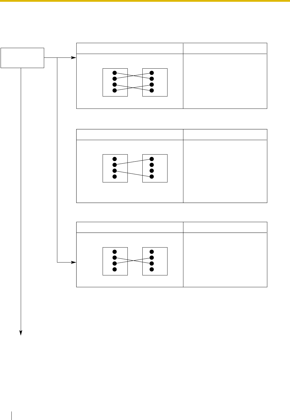
4.1 Troubleshooting
222 Installation Manual
4.1.2 Connection
Connection between the Hybrid IP-PBX and a PT:
Connection between the Hybrid IP-PBX and an SLT:
Connection between the Hybrid IP-PBX and an SLT that is polarity-sensitive:
CAUSE
The T/R is connected to the D1/D2.
SOLUTION
Use the correct cord (the
inner 2 wires are for T/R and
the outer 2 wires are for
D1/D2).
D1
T
R
D2
D1
T
R
D2
Hybrid IP-PBX
Hybrid IP-PBX
Hybrid IP-PBX
Extension
CAUSE
The T/R is connected to the D1/D2.
SOLUTION
Use the correct cord (the
inner 2 wires are for T/R).
•
D1
T
R
D2
T
R
Extension
CAUSE
The "T" is connected to the "R".
SOLUTION
Reverse the connections of
the T/R.
D1
T
R
D2
T
R
Extension
Can you dial
an extension?
(Continued on the next page.)
No
Ye s
If a telephone equipped
with an A-A1 relay is
connected to the Hybrid
IP-PBX, set the A-A1
relay switch of the
telephone to "OFF".
4.1 Troubleshooting
Installation Manual 223
Connection between the trunk and the Hybrid IP-PBX:
CAUSE
Trunk is connected to the T2/T1.
Trunk is connected to the T2/R1.
SOLUTION
Reconnect the trunk to
the T1/R1 or T2/R2 of the
telephone jack using
2-conductor wiring.
T2
R1
T1
R2
Trunk Hybrid IP-PBX
Hybrid IP-PBX
Trunk
T2
R1
T1
R2
(Continued from the
previous page.)
Can you dial
out on a
trunk?
No

4.1 Troubleshooting
224 Installation Manual
4.1.3 Operation
PROBLEM PROBABLE CAUSE SOLUTION
• When using the
speakerphone on an APT,
nothing is audible.
• The HANDSET/HEADSET
selector is set to the
"HEADSET" position.
• When the headset is not used, set the
HANDSET/HEADSET selector to the
"HANDSET" position.
• When using the
speakerphone/monitor
mode with a DPT, nothing is
audible.
• The "HEADSET" mode is
selected by Personal
Programming, "Handset/
Headset Selection".
• When the headset is not used, select
the "HANDSET" mode by Personal
Programming.
• The PT does not ring. • The ringer volume is off. • Turn on the ringer volume.
• During a power failure,
extensions connected to
ports 1 to 4 of MSLC16/
SLC16 and ports 1 to 2 of
DHLC8/SLC8 cards do not
operate.
• A DPT or APT is connected
to the extension port.
• The dialling mode (tone or
pulse) is incorrect.
• Disconnect the DPT or APT and
connect an SLT.
• Set the Tone/Pulse switch to the other
position.
• Originating an outside call,
call transfer, or conference
cannot be performed.
• The corresponding CO
button does not exist on the
PT.
• Programme the CO button. Refer to
"1.19.2 Flexible Buttons" in the Feature
Guide.
• Cannot register the PS. • Wrong Personal
Identification Number (PIN)
is registered to the PS.
• Enter the PIN set to the Hybrid IP-PBX
into the PS.
• CS is not connected
properly.
• Make sure that the cable is connected
properly with correct pin assignments.
Also, make sure that the cable does not
make short circuits.
• Switch all DIP switches off.
• PS becomes out of range. • CSIF card is not working. • Install the CSIF card properly.
• Cannot make calls using the
PS.
• CS is not working. • Make sure that the cable is connected
properly with correct pin assignments.
Also, make sure that the cable does not
make short circuits.
• Switch all DIP switches off.
• Location of CS is not good. • Locate the CS properly (refer to "2.8.5
Site Survey Using the KX-TCA255/KX-
TD7590" or "2.9.5 Site Survey" ).
• Access system of the PS is
not properly set.
• Change the access system setting of
the PS to the appropriate system or
automatic.
• Noise is frequent while using
the PS.
• Conversations disconnect
while using the PS.
• Call handover is not
working.
• PS is out of CS coverage
area.
• Locate the CS properly (refer to "2.8.5
Site Survey Using the KX-TCA255/KX-
TD7590" or "2.9.5 Site Survey" ).

4.1 Troubleshooting
Installation Manual 225
• PS stays out of service
when the CS status is
changed from Out of
Service to In Service.
• It may take about 20 s for
CS to start up after the
status has been changed to
In Service.
• Wait until the CS starts up.
PROBLEM PROBABLE CAUSE SOLUTION
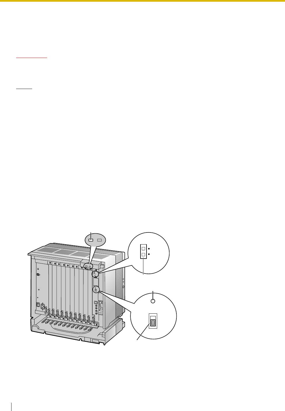
4.1 Troubleshooting
226 Installation Manual
4.1.4 Using the Reset Button
If the Hybrid IP-PBX does not operate properly, use the Reset Button. Before using the Reset Button, try
the system feature again to confirm whether there definitely is a problem or not.
CAUTION
In order to avoid possible corruption of data on the SD Memory Card, please ensure that the "SD
ACCESS" LED is off before pressing the Reset Button.
Notes
• When the System Initialise Switch is set to "NORMAL", pressing the Reset Button causes the
following:
– Camp-on is cleared.
– Calls on hold are terminated.
– Calls on exclusive hold are terminated.
– Calls in progress are terminated.
– Call park is cleared.
Other data stored in memory, except the above, are not cleared.
• Be aware that pressing the Reset Button with the System Initialise Switch in the "SYSTEM
INITIALIZE" position clears all data stored in the Hybrid IP-PBX. Do not perform this operation
unless you intend to delete all data from the Hybrid IP-PBX.
Operation
If the Hybrid IP-PBX does not operate properly:
1. Slide the System Initialise Switch to the "NORMAL" position.
2. Press the Reset Button for about 1 second.
System Initialise Switch
Reset Button
SYSTEM
INITIALIZE
RESET
NORMAL
RUN Indicator
BATT
ALARM
SD
ACCESS
LED
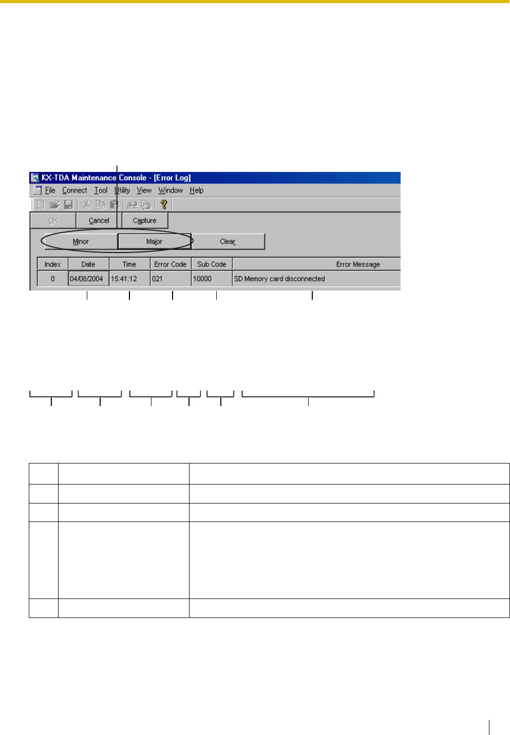
4.1 Troubleshooting
Installation Manual 227
4.1.5 Troubleshooting by Error Log
When a major system error occurs in the Hybrid IP-PBX, the ALARM indicator on the front of the shelf turns
on red, and the system logs the error information.
Error Log Display Format
Below is the display format of the error log. To see the error log using the KX-TDA Maintenance Console,
refer to the on-line help of the KX-TDA Maintenance Console.
Example: KX-TDA Maintenance Console
Example: Station Message Detail Recording (SMDR)
Description
Item Description
1 Date Date of the error detection
2 Time Time of the error detection
3 Level Major Alarm (MJ ALM):
Errors that affect the whole system operation, or result in system
failure
Minor Alarm (MN ALM):
Errors that affect certain part of system operation
4 Error Code Three-digit error code
124 5 6
3
04/01/01 10:37AM MJ ALM #000 10000 MPR WDT overflow
04/01/01 11:07AM MN ALM #010 10000 AC power down
04/01/01 03:55PM MN ALM #301 10501 Digital trunk RAI reception
12 345 6

4.1 Troubleshooting
228 Installation Manual
5 Sub Code Five-digit sub code (1XXYY)
1: Shelf number
XX: Slot number
KX-TDA100: 00 to 06 (00: MPR slot; 01 to 06: Free slot)
KX-TDA200: 00 to 11 (00: MPR slot; 01 to 11: Free slot)
YY: Physical port number (01 to 16)
For OPB3 card, sub slot number + port number will be displayed.
Sub slot 1: 11 to 14
Sub slot 2: 21 to 24
Sub slot 3: 31 to 34
Note
When there is no parameter for slot and physical port number, XX
and YY will be displayed as "00".
Example: Sub code for MPR card = 10000
6 Error Message Error description
Item Description

4.1 Troubleshooting
Installation Manual 229
List of Errors and Solutions
The tables below list the errors and their solutions.
When an error whose error code is indicated with "*" occurs in the Hybrid IP-PBX, the ALARM indicator on
the front of the shelf turns on red, and the system logs the error information.
When the error conditions indicated by the error codes "021", "091", "092", "230", and "510" are recovered,
the ALARM indicator will turn off automatically, indicating successful troubleshooting. When other errors are
logged, the ALARM indicator will turn off only when the log for major or minor errors is cleared from the KX-
TDA Maintenance Console.
In other words, the ALARM indicator will turn off under the following conditions:
•When the errors "021", "091", "092", "230", and "510" are logged: when the error conditions
are recovered
•When other errors are logged: when the log for major or minor errors is cleared from the KX-TDA
Maintenance Console
LPR (Optional Service Card with Local Processor) Initial Self Diagnosis
Error Code Error Message PROBABLE CAUSE SOLUTION
211 Speech path
loop-back check
error
• Optional service card
malfunction: DHLC, DLC,
SLC, CSIF, LCOT, T1, E1,
BRI, PRI, OPB3, E&M, IP-
GW, DID
• See if the corresponding optional
service card is installed properly
• Pull out and re-insert the
corresponding optional service card
• Press the Reset Button
• Replace the corresponding optional
service card
212 Echo canceller
access error
• Optional service card
malfunction: CSIF, ECHO
214 DSP Boot check
error
• Optional service card
malfunction: T1, E1
215 Framer IC access
error
• Optional service card
malfunction: T1, E1, BRI, PRI
216 MSG card DSP
error
• Optional service card
malfunction: MSG, OPB3
217 MSG card data
error
• Optional service card
malfunction: MSG, OPB3
• Erroneous recording of
messages
• See if the corresponding optional
service card is installed properly
• Pull out and re-insert the
corresponding optional service card
• Press the Reset Button
• Re-record the messages
• Replace the corresponding optional
service card
218 LANC register
access error
• Detection of accessing error
to LAN controller of CTI-LINK
card
• See if the corresponding optional
service card is installed properly
• Pull out and re-insert the
corresponding optional service card
• Replace the corresponding optional
service card

4.1 Troubleshooting
230 Installation Manual
System Start-up and On-line Operation
220 Flash ROM
access error
• Detection of accessing error
to Flash ROM of optional
service card
• See if the corresponding optional
service card is installed properly
• Pull out and re-insert the
corresponding optional service card
• Replace the corresponding optional
service card
Error Code Error Message PROBABLE CAUSE SOLUTION
000* MPR WDT overflow • MPR card malfunction
• Optional service card
malfunction: CTI-LINK
• Erroneous processing of
MPR card software
• Software error due to
external factors
• Press the Reset Button
• Reprogramme the Hybrid IP-PBX
• Replace the MPR card (be sure to turn
off the Hybrid IP-PBX when replacing)
001 SDRAM bit error
002 System Restart • Reset Button is pressed
• Power failure
• MPR card malfunction
• Erroneous processing of
MPR card software
• Software error due to
external factors
• Ignore if not frequent
• Press the Reset Button
• Reprogramme the Hybrid IP-PBX
• Replace the MPR card (be sure to turn
off the Hybrid IP-PBX when replacing)
010* AC power down • Power supply system
malfunction (e.g., power
failure, power noise,
trouble with UPS)
• Bad connection or
breaking of AC cord
• Power supply circuit (PSU,
back board) malfunction
• Check the power supply system
• See if the AC cord is connected
properly
• Check the AC cord
• Replace the AC cord (be sure to turn
off the Hybrid IP-PBX when replacing)
• Replace the PSU (be sure to turn off
the Hybrid IP-PBX when replacing)
• Replace the back board (be sure to
turn off the Hybrid IP-PBX when
replacing)
Error Code Error Message PROBABLE CAUSE SOLUTION

4.1 Troubleshooting
Installation Manual 231
011* DC power down • AC power down
• Power supply circuit (PSU,
back board) malfunction
• Detection of over current
(short circuit on optional
service cards)
• Check the power supply system
• See if the AC cord is connected
properly
• Check the AC cord
• Replace the AC cord (be sure to turn
off the Hybrid IP-PBX when replacing)
• Replace the PSU (be sure to turn off
the Hybrid IP-PBX when replacing)
• Replace the back board (be sure to
turn off the Hybrid IP-PBX when
replacing)
• Remove the optional service cards and
restart the Hybrid IP-PBX
012* MPR RAM battery
low
• Battery out
• MPR card malfunction
• Replace the MPR card (be sure to turn
off the Hybrid IP-PBX when replacing)
014* FAN Alarm • PSU-L malfunction • See if anything is jammed in the fan
• Replace the PSU (be sure to turn off
the Hybrid IP-PBX when replacing)
016 CS overload • Defective cable
• CS malfunction
• Optional service card
malfunction: CSIF
• Check the cable diameter and length
• Replace the CS
• Replace the corresponding optional
service card
017 BRI port overload • Defective cable
• Defective ISDN terminal
equipment
• Optional service card
malfunction: BRI
• Check the cable
• Replace the defective terminal
equipment
• Check the number of connected
terminal equipment
• Replace the corresponding optional
service card
020* SD file access error • SD Memory Card
malfunction
• Bad connection of SD
Memory Card
• MPR card malfunction
• Press the Reset Button
• Reprogramme the Hybrid IP-PBX
• Replace the SD Memory Card
• Replace the MPR card (be sure to turn
off the Hybrid IP-PBX when replacing)
021* SD Memory Card
disconnected
• SD Memory Card not
installed
• Bad connection of SD
Memory Card
• SD Memory Card
malfunction
• MPR card malfunction
Error Code Error Message PROBABLE CAUSE SOLUTION

4.1 Troubleshooting
232 Installation Manual
022 Not enough free
space on SD card
• Not enough memory
space available to save
the system data, or to
upload system files from
the KX-TDA Maintenance
Console
• Delete the files whose file names start
with "$" from SD Memory Card
• Delete the "Pxxx" files (old programme
files of optional service cards) from SD
Memory Card. "xxx" indicates the card
type (e.g., "PDHLC" for DHLC card)
Note
Do not delete the "PMPR" file; it is the
programme file of the MPR card.
023 System data file
version error
• Old system files on SD
Memory Card
• Defective system files on
SD Memory Card
• Restore the backup files
• Re-install the software
024 System initialization
file version error
025 Card initialization file
version error
026 LCD file version error
027 System data file
checksum error
028 System initialization
file checksum error
029 Card initialization file
checksum error
030 LCD file checksum
error
031* System data file not
found
• SD Memory Card not
installed
• Bad connection of SD
Memory Card
• SD Memory Card
malfunction
• MPR card malfunction
• Press the Reset Button
• Reprogramme the Hybrid IP-PBX
• Replace the SD Memory Card
• Replace the MPR card (be sure to turn
off the Hybrid IP-PBX when replacing)
032* System initialization
file not found
033* Card initialization file
not found
034* LCD file not found
035 System data file
access error
036* System initialization
file access error
037* Card initialization file
access error
038* LCD file access error
039* SD file access error
Error Code Error Message PROBABLE CAUSE SOLUTION

4.1 Troubleshooting
Installation Manual 233
041* Expansion Memory
Card Failure
• MEC card is not properly
connected
• See if the corresponding optional
service card is installed properly
• Pull out and re-insert the
corresponding optional service card
• Replace the corresponding optional
service card
090 Over Card Limitation • Too many optional service
cards installed
• Reduce the number of optional service
cards
091* PT connection over • Too many PTs connected • Reduce the number of PTs
092* CS connection over • Too many CSs connected • Reduce the number of CSs
200 LPR start up error
(ROM NG)
• Optional service card
malfunction: DHLC, DLC,
CSIF, T1, E1, BRI, PRI,
OPB3, CTI-LINK, E&M,
IP-GW, DID, SLC8, IP-
EXT, LCOT
• Pull out and re-insert the
corresponding optional service card
• Press the Reset Button
• Replace the corresponding optional
service card
201* LPR start up error
(RAM NG)
202* LPR start up error
(No Program)
• Optional service card
malfunction: DHLC, DLC,
CSIF, T1, E1, BRI, PRI,
OPB3, CTI-LINK, E&M,
IP-GW, DID, SLC8, IP-
EXT, LCOT
• Pull out and re-insert the
corresponding optional service card
• Press the Reset Button
• Update the software of the
corresponding optional service card
• Replace the corresponding optional
service card
203* LPR start up error
(Version NG)
204* LPR start up error
(Download NG)
205* LPR start up error
(No response)
206 LPR start up error
(Card type NG)
207 LPR start up error
(Check SUM NG)
230* Card disconnected • Optional service card not
installed properly
• Optional service card
malfunction
• Back board malfunction
• See if the corresponding optional
service card is installed properly
• Pull out and re-insert the
corresponding optional service card
• Press the Reset Button
• Replace the corresponding optional
service card
• Replace the back board (be sure to
turn off the Hybrid IP-PBX when
replacing)
Error Code Error Message PROBABLE CAUSE SOLUTION

4.1 Troubleshooting
234 Installation Manual
231 LPR alive check error • Optional service card
malfunction: DHLC, DLC,
CSIF, T1, E1, BRI, PRI,
OPB3, CTI-LINK, E&M,
IP-GW, DID, SLC8, IP-
EXT, LCOT
• Back board malfunction
• MPR card malfunction
• See if the corresponding optional
service card is installed properly
• Pull out and re-insert the
corresponding optional service card
• Press the Reset Button
• Replace the corresponding optional
service card
• Replace the back board (be sure to
turn off the Hybrid IP-PBX when
replacing)
• Replace the MPR card (be sure to turn
off the Hybrid IP-PBX when replacing)
232 MPR-LPR
communication error
233 LPR data check error
234 DPLL clock failure
235* CS clock failure • Optional service card
malfunction: CSIF
• Replace the corresponding optional
service card
250* T1/E1 DSP failure • Optional service card
malfunction: T1, E1
• See if the corresponding optional
service card is installed properly
• Replace the corresponding optional
service card
251 MSG DSP failure • Optional service card
malfunction: MSG
300* Digital trunk out of
synchronization
• Network (digital trunk)
malfunction
• Optional service card
malfunction: PRI, T1, E1
• Wrong A/B switch setting:
PRI, T1, E1
• Wrong termination switch
setting: PRI30, E1
• Check the signals from the network
• Check the cable
• See if the A/B switch is set to A on the
corresponding optional service card
• See if the termination switch is set
properly on the corresponding optional
service card: 120 Ω when using RJ45
connector; 75 Ω when using BNC
connector
• See if the corresponding optional
service card is installed properly
• Replace the corresponding optional
service card
301* Digital trunk RAI
reception
302* Digital trunk AIS
reception
303* Multiframe out of
synchronization
304* Frame error
305* Data Link failure • Data link between the CS
and CSIF card or DHLC/
DLC card failed
• Data link between the
network and PRI/BRI card
failed
• Data link between the
network and IP-GW card
failed
• Check the connection between the CS
and CSIF card or DHLC/DLC card
• Check the connection between the
network and PRI/BRI card
• Check the connection between the
network and IP-GW card
Error Code Error Message PROBABLE CAUSE SOLUTION

4.1 Troubleshooting
Installation Manual 235
306 E1 Channel Block
failure
• Network (digital trunk)
malfunction
• Optional service card
malfunction: E1
• Wrong A/B switch setting:
E1
• Wrong termination switch
setting: E1
• Check the signals from the network
• Check the cable
• See if the A/B switch is set to A on the
corresponding optional service card
• See if the termination switch is set
properly on the corresponding optional
service card: 120 Ω when using RJ45
connector; 75 Ω when using BNC
connector
• See if the corresponding optional
service card is installed properly
• Replace the corresponding optional
service card
307 LAN No Carrier • IP-GW card not connected
to the LAN
• Check the connection between the
LAN and IP-GW card
308 IP-GW LAN Loop
back Error
• Detection of IP-GW LAN
Loop back Test error
• Replace the corresponding optional
service card
• Collect the log data of IP-GW (refer to
the documentation for the IP-GW card)
309 IP-GW Core Data
Link Error
• Detection of IP-GW Core
data Link error
• Press the Reset Button
• Collect the log data of IP-GW (refer to
the documentation for the IP-GW card)
310* Port Link Failure • Voice Processing System
malfunction
• Ports defective on optional
service card: DHLC, DLC
• Check the Voice Processing System
• See if the corresponding optional
service card is installed properly
• Replace the corresponding optional
service card
320 IP-GW H.323
Dummy Call Test
Error
• Detection of IP-GW H.323
Dummy Call Test error
• Replace the corresponding optional
service card
• Collect the log data of IP-GW (refer to
the documentation for the IP-GW card)
321 IP-GW Gatekeeper
Error
• Detection of Gatekeeper
access error
• Check the IP address setting of the
Gatekeeper
• Check whether the Gatekeeper is
connected to the network and work
properly
• Check the route to the Gatekeeper
322 IP-GW Gatekeeper
Registration Error
• Gatekeeper Registration
is failed
• Check the Gatekeeper setting
323 IP-GW SDRAM
Failure
• Detection of IP-GW
SDRAM error
• Replace the corresponding optional
service card
324 IP-GW DPRAM
Failure
• Detection of IP-GW
DPRAM error
• Replace the corresponding optional
service card
Error Code Error Message PROBABLE CAUSE SOLUTION

4.1 Troubleshooting
236 Installation Manual
325 IP-GW LAN Chip
Failure
• Detection of IP-GW LAN
Chip failure
• Replace the corresponding optional
service card
• Collect the log data of IP-GW (refer to
the documentation for the IP-GW card)
326 IP-GW Stop • IP-GW is stopped from a
remote maintenance PC
• This information is logged when IP-GW
is stopped from a remote maintenance
PC
327 IP-GW DSP failure • Optional service card
malfunction: IP-GW16
• Replace the corresponding optional
service card
330 Loop current
detection error
• Detection of LCOT loop
current error
• Change the corresponding trunk status
back to In Service
• Enter the feature number to clear Busy
Out status
• The trunk status is automatically
changed back to In Service by system
diagnosis performed at a
preprogrammed time every day
350 IP-unit SDRAM bit
error
• Optional service card
malfunction: IP-EXT
• The IP-EXT card will be rebooted
automatically if the error is temporary
• Replace the corresponding IP-EXT
card if the card is not started up
correctly
351 IP-unit download
data check-sum error
352 IP-unit DSP failure • Optional service card
malfunction: IP-EXT
• Replace the corresponding optional
service card
353 IP-PT DSP failure • IP-PT malfunction • The IP-PT will be rebooted
automatically if the error is temporary
• Replace the corresponding IP-PT if the
IP-PT is not started up correctly
355 IP-unit alive check
error
• Optional service card
malfunction: IP-EXT
• The IP-EXT card will be rebooted
automatically if the error is temporary
• Replace the corresponding IP-EXT
card if the card is not started up
correctly
356 IP/TEL-unit
communication error
357 IP-unit FLASH
access error
• Optional service card
malfunction: IP-EXT
• Replace the corresponding optional
service card
358 IP-unit boot error
359 IP-unit DSP failure
(boot diagnosis)
360 IP-PT SUB-CPU
failure
• IP-PT malfunction • The IP-PT will be rebooted
automatically if the error is temporary
• Replace the corresponding IP-PT if the
IP-PT is not started up correctly
361 IP-PT DHCP server
no response
• DHCP server is not active
• Network malfunction
• Consult your network administrator
Error Code Error Message PROBABLE CAUSE SOLUTION

4.1 Troubleshooting
Installation Manual 237
362 IP-PT Rebooted
(cause DHCP
server)
• DHCP server is not active
• Network malfunction
• Network configuration has
been changed
• Consult your network administrator
370 IP-GW Rebooted by
Maintenance
Console
• IP-GW is rebooted from a
remote maintenance PC
• This information is logged when IP-GW
is rebooted from a remote
maintenance PC
371 IP-GW Rebooted • Optional service card
malfunction: IP-GW
• Check whether the software version of
the IP-GW card is correct
• Replace the corresponding optional
service card
372 NDSS message over
IPGW notification -
caused by IPGW Tx
resource limitation
• Optional service card
malfunction: IP-GW
• Ignore if not frequent
• Change the IP-GW card status to Out
of Service, and then back to In Service
373 NDSS message over
IPGW notification -
caused by IPGW Rx
resource limitation
374 NDSS message over
IPGW notification -
caused by shortage
of IPGW resource
375 NDSS message over
IPGW notification -
caused by Network
side
• Network malfunction • Ignore if not frequent
• Consult your network administrator
390 Digital signal
synchronization
established
• Synchronisation of digital
line established or
restored
• This information is logged when
synchronisation of digital line is
established, and does not indicate an
error condition that needs to be solved
391 Data Link
established
• Connection with PC
Phone/PC Console or
Voice Processing System
(DPT Integration)
established or restored
• This information is logged when
connection with PC Phone/PC
Console or Voice Processing System
(DPT Integration) is established, and
does not indicate an error condition
that needs to be solved.
However, if this is logged frequently
(with "305 Data Link failure"), check the
connection as it may not be done
properly.
392 Clock master card
selected
• Clock master card has
been changed to the one
indicated by the sub code
• Check if the proper card is selected as
the new clock master card
393 LAN Carrier detected • IP-GW card connected to
the LAN
• This information is logged when
synchronisation of LAN is established
Error Code Error Message PROBABLE CAUSE SOLUTION

4.1 Troubleshooting
238 Installation Manual
394 IP-GW Core Data
Link established
• IP-GW Core Data Link
established
• This information is logged when IP-GW
Core Data Link is recovered
395 IP-GW Gatekeeper
Error Cleared
• Connection to the
Gatekeeper is recovered
• This information is logged when
connection to the Gatekeeper is
recovered
396 IP-GW Run • IP-GW is started from a
remote maintenance PC
• This information is logged when IP-GW
is started from a remote maintenance
PC
510* SMDR disconnect • RS-232C cable not
connected
• Breaking of RS-232C
cable
• Printer (terminal
equipment) malfunction
• Check the RS-232C cable
• Check the terminal equipment
Error Code Error Message PROBABLE CAUSE SOLUTION

Installation Manual 239
Section 5
Appendix

5.1 Revision History
240 Installation Manual
5.1 Revision History
5.1.1 PMPR Software File Version 1.1xxx
New Options
• System Components Table
New Contents
• 2.7.3 Digital EXtra Device Port (Digital XDP) Connection
Changed Contents
• 1.4.3 System Capacity
• KX-TDA0105 Memory Expansion Card (MEC)
• KX-TDA0182 8-Port DID Card (DID8)
• KX-TDA0183 4-Port Analogue Trunk Card (LCOT4)
• KX-TDA0484 4-Channel VoIP Gateway Card (IP-GW4E)
• KX-TDA0143 4 Cell Station Interface Card (CSIF4)
• KX-TDA0141CE 2-Channel Cell Station Unit Using a DHLC/DLC Card (PT-interface CS) for
DECT Portable Station
• KX-TDA0141 2-Channel Cell Station Unit Using a DHLC/DLC Card (PT-interface CS) for
2.4 GHz Portable Station

5.1 Revision History
Installation Manual 241
5.1.2 PMPR Software File Version 2.0xxx
New Options
• System Components Table
Changed Contents
• 1.4.3 System Capacity
• 2.10.1 Connection of Doorphones, Door Openers, External Sensors, and External Relays
• KX-TDA0490 16-Channel VoIP Gateway Card (IP-GW16)
• KX-TDA0470 16-Channel VoIP Extension Card (IP-EXT16)
• KX-TDA0164 4-Port External Input/Output Card (EIO4)
• KX-TDA0168 Extension Caller ID Card (EXT-CID)
• KX-TDA0820 SD Memory Card for Software Upgrade
• KX-TDA0920 SD Memory Card for Software Upgrade to Enhanced Version


Installation Manual 243
Index

Index
244 Installation Manual
Numerics
16-Channel Echo Canceller Card (KX-TDA0166)
23, 132
16-Channel VoIP Extension Card (KX-TDA0470)
24, 121
16-Channel VoIP Gateway Card (KX-TDA0490)
25, 105
16-Port Analogue Trunk Card (KX-TDA0181)
24, 75
16-Port Digital Extension Card (KX-TDA0172)
23, 114
16-Port Single Line Telephone Extension Card (KX-TDA0174)
23, 119
16-Port Single Line Telephone Extension with Message Lamp Card (KX-
TDA0175)
24, 119
2.4 GHz Portable Station
173
2.4 GHz Portable Station, After Site Survey
187
2.4 GHz Portable Station, Before Site Survey
181
2.4 GHz Portable Station, Connecting a CS
188
2.4 GHz Portable Station, Procedure Overview
175
2.4 GHz Portable Station, Site Planning
177
2.4 GHz Portable Station, Site Survey
183
2-Port Doorphone Card (German Type) (KX-TDA0162)
23, 126
4 Cell Station Interface Card (KX-TDA0143)
23, 107
4-Channel Message Card (KX-TDA0191)
24, 133
4-Channel VoIP Gateway Card (KX-TDA0480)
25, 101
4-Channel VoIP Gateway Card (KX-TDA0484)
25, 103
4-Port Analogue Trunk Card (KX-TDA0183)
24, 75
4-Port BRI Card (KX-TDA0284)
24, 90
4-Port Doorphone Card (KX-TDA0161)
23, 124
4-Port External Input/Output Card (KX-TDA0164)
23, 129
8 Cell Station Interface Card (KX-TDA0144)
23, 107
8-Port Analogue Trunk Card (KX-TDA0180)
24, 75
8-Port BRI Card (KX-TDA0288)
24, 90
8-Port Caller ID Card (KX-TDA0193)
24, 80
8-Port Caller ID/Pay Tone Card (KX-TDA0189)
24, 79
8-Port DID Card (KX-TDA0182)
24, 77
8-Port Digital Extension Card (KX-TDA0171)
23, 112
8-Port Digital Hybrid Extension Card (KX-TDA0170)
23, 109
8-Port E & M Trunk Card (KX-TDA0184)
24, 81
8-Port Single Line Telephone Extension Card (KX-TDA0173)
23, 116
A
About the software version of your Hybrid IP-PBX
11
Amphenol Connector
60, 61
B
Backup Battery Connection
49
Backup Power Supply Duration
49
Basic Shelf
20
Basic Shelf, Construction
20
BGM
201
Blank Slot Cover
53
BRI4 Card (KX-TDA0284)
90
BRI8 Card (KX-TDA0288)
90
C
Cable Distance
136
Cable Handling
54
Changed Contents
240, 241, 242
Characteristics
28
CID/PAY8 Card (KX-TDA0189)
79
CID8 Card (KX-TDA0193)
80
Components, System
2
Connecting Backup Batteries
50
Connection Diagram, System
21
Connector Types
56
Cover for Blank Slot
53
CS (for 2.4 GHz Portable Station)
173, 188
CS (for DECT Portable Station)
145, 162
CSIF4 Card (KX-TDA0143)
107
CSIF8 Card (KX-TDA0144)
107
CTI Link Card (KX-TDA0410)
24, 134
CTI Server Connection (via USB version 2.0)
204
CTI-LINK Card (KX-TDA0410)
134
CTI—First Party Call Control
144
CTI—Third Party Call Control
134, 204
D
DECT Portable Station
145
DECT Portable Station, After Site Survey
161
DECT Portable Station, Before Site Survey
153
DECT Portable Station, Connecting a CS
162
DECT Portable Station, Procedure Overview
147
DECT Portable Station, RF Specification
145
DECT Portable Station, Site Planning
149
DECT Portable Station, Site Survey
157
DHLC8 Card (KX-TDA0170)
109
DID8 Card (KX-TDA0182)
77
Digital EXtra Device Port (Digital XDP) Connection
139
Digital XDP
139
Digital XDP Connection, Using a Modular T-Adaptor
139, 141
Digital XDP Connection, Using an EXtra Device Port
140, 142
DLC16 Card (KX-TDA0172)
114
DLC8 Card (KX-TDA0171)
112
Door Opener
124, 126, 198
Doorphone
124, 126, 198
DPH2 Card (KX-TDA0162)
126
DPH4 Card (KX-TDA0161)
124
E
E&M8 Card (KX-TDA0184)
81
E1 Card (KX-TDA0188)
87
E-1 Trunk Card (KX-TDA0188)
24, 87
ECHO16 Card (KX-TDA0166)
132
EIO4 Card (KX-TDA0164)
129
Error Log
227
EXT-CID Card (KX-TDA0168)
118
Extension Caller ID Card (KX-TDA0168)
23, 118
External Relay
129, 131, 198
External Sensor
129, 131, 198
EXtra Device Port (XDP) Mode
137, 139
F
Ferrite Core
58
First Party Call Control CTI Connection
144
Floor Standing (KX-TDA200 Only)
66
Frame Earth Connection
48
Front Cover, Closing
43
Front Cover, Opening
42

Index
Installation Manual 245
I
Installation Precautions
38
IP-EXT16 Card (KX-TDA0470)
121
IP-GW16 Card (KX-TDA0490)
105
IP-GW4 Card (KX-TDA0480)
101
IP-GW4E Card (KX-TDA0484)
103
K
KX-TDA Maintenance Console, Connection
213
KX-TDA Maintenance Console, Installation
216
KX-TDA Maintenance Console, Overview
212
KX-TDA Maintenance Console, Password Security
215
KX-TDA Maintenance Console, Quick Setup
216
KX-TDA Maintenance Console, System Requirements
215
KX-TDA0103 (L-Type Power Supply Unit)
23, 44
KX-TDA0104 (M-Type Power Supply Unit)
23, 44
KX-TDA0105 (Memory Expansion Card)
23, 73
KX-TDA0108 (S-Type Power Supply Unit)
23, 44
KX-TDA0143 (4 Cell Station Interface Card)
23, 107
KX-TDA0144 (8 Cell Station Interface Card)
23, 107
KX-TDA0161 (4-Port Doorphone Card)
23, 124
KX-TDA0162 (2-Port Doorphone Card (German Type))
23, 126
KX-TDA0164 (4-Port External Input/Output Card)
23, 129
KX-TDA0166 (16-Channel Echo Canceller Card)
23, 132
KX-TDA0168 (Extension Caller ID Card)
23, 118
KX-TDA0170 (8-Port Digital Hybrid Extension Card)
23, 109
KX-TDA0171 (8-Port Digital Extension Card)
23, 112
KX-TDA0172 (16-Port Digital Extension Card)
23, 114
KX-TDA0173 (8-Port Single Line Telephone Extension Card)
23, 116
KX-TDA0174 (16-Port Single Line Telephone Extension Card)
23, 119
KX-TDA0175 (16-Port Single Line Telephone Extension with Message Lamp
Card)
24, 119
KX-TDA0180 (8-Port Analogue Trunk Card)
24, 75
KX-TDA0181 (16-Port Analogue Trunk Card)
24, 75
KX-TDA0182 (8-Port DID Card)
24, 77
KX-TDA0183 (4-Port Analogue Trunk Card)
24, 75
KX-TDA0184 (8-Port E & M Trunk Card)
24, 81
KX-TDA0187 (T-1 Trunk Card)
24, 84
KX-TDA0188 (E-1 Trunk Card)
24, 87
KX-TDA0189 (8-Port Caller ID/Pay Tone Card)
24, 79
KX-TDA0190 (Optional 3-Slot Base Card)
24, 123
KX-TDA0191 (4-Channel Message Card)
24, 133
KX-TDA0193 (8-Port Caller ID Card)
24, 80
KX-TDA0196 (Remote Card)
24, 74
KX-TDA0284 (4-Port BRI Card)
24, 90
KX-TDA0288 (8-Port BRI Card)
24, 90
KX-TDA0290 (PRI Card [PRI23])
24, 98
KX-TDA0290CE/CJ (PRI Card [PRI30])
24, 94
KX-TDA0410 (CTI Link Card)
24, 134
KX-TDA0470 (16-Channel VoIP Extension Card)
24, 121
KX-TDA0480 (4-Channel VoIP Gateway Card)
25, 101
KX-TDA0484 (4-Channel VoIP Gateway Card)
25, 103
KX-TDA0490 (16-Channel VoIP Gateway Card)
25, 105
KX-TDA0820 (SD Memory Card for Software Upgrade)
25, 71
KX-TDA0920 (SD Memory Card for Software Upgrade to Enhanced
Version)
25, 71
L
LCOT16 Card (KX-TDA0181)
75
LCOT4 Card (KX-TDA0183)
75
LCOT8 Card (KX-TDA0180)
75
LED Indications, Hybrid IP-PBX
210
Load Figure Calculation
34
L-Type Power Supply Unit (KX-TDA0103)
23, 44
M
Main Processing Card (MPR Card)
71
Maintenance Console
212
Master DPT, Digital XDP
139
Maximum Optional Service Cards
29
Maximum Terminal Equipment
32
MEC Card (KX-TDA0105)
73
MEC Card Calculation
33
Memory Expansion Card (KX-TDA0105)
23, 73
MOH
201
MPR Card
71
MSG4 Card (KX-TDA0191)
133
MSLC16 Card (KX-TDA0175)
119
M-Type Power Supply Unit (KX-TDA0104)
23, 44
N
Names and Locations
41
New Contents
240
New Options
240, 241
O
OPB3 Card (KX-TDA0190)
123
Optional 3-Slot Base Card (KX-TDA0190)
24, 123
Optional Equipment
23
Optional Service Card, Installation
51
Optional Service Card, Maximum Number
29
Optional Service Card, Removal
55
P
Pager
202
Parallel Connection of the Extensions
137
Parallel Connection, Using a Modular T-Adaptor
137
Parallel Connection, Using an EXtra Device Port
138
Parallel Mode
137, 139
Password Security
215
PC Connection (via RS-232C)
202
PC Connection (via USB version 2.0)
204
PMPR Software File Version 1.1xxx
240
PMPR Software File Version 2.0xxx
241
PMPR Software File Version 3.0xxx
242
Power Failure Connections
205
Power Supply Unit
44
Power Supply Unit Selection
34
Power Supply Unit, Installation
45
Power Supply Unit, Replacement
46
PRI Card (PRI23) (KX-TDA0290)
24, 98
PRI Card (PRI30) (KX-TDA0290CE/CJ)
24, 94
PRI23 Card (KX-TDA0290)
98
PRI30 Card (KX-TDA0290CE/CJ)
94
Printer Connection (via RS-232C)
202
PSU
44
PSU Capacity
34

Index
246 Installation Manual
PSU-L
34, 44
PSU-M
34, 44
PSU-S
34, 44
Q
Quick Setup
216
R
Remote Card (KX-TDA0196)
24, 74
Reset Button
226
Revision History
240
RF Specification, DECT Portable Station
145
RMT Card (KX-TDA0196)
74
RUN Indicator
209
S
Safety Installation Instructions
38
Safety Instructions
44
SD Memory Card
71
SD Memory Card for Software Upgrade (KX-TDA0820)
25, 71
SD Memory Card for Software Upgrade to Enhanced Version (KX-
TDA0920)
25, 71
Site Planning, 2.4 GHz Portable Station
177
Site Planning, DECT Portable Station
149
Site Survey, 2.4 GHz Portable Station
183
Site Survey, DECT Portable Station
157
Slave DPT, Digital XDP
139
SLC16 Card (KX-TDA0174)
119
SLC8 Card (KX-TDA0173)
116
Specifications
26
Specifications, Characteristics
28
Specifications, General Description
26
Specifications, System Capacity
29
Starting the Hybrid IP-PBX
209
S-Type Power Supply Unit (KX-TDA0108)
23, 44
Surge Protector Installation
68
System Capacity
29
System Components Table
2
System Connection Diagram
21
System Highlights
18
System Initialise Switch
209, 226
System Requirements
215
T
T1 Card (KX-TDA0187)
84
T-1 Trunk Card (KX-TDA0187)
24, 84
Terminal Equipment, Maximum Number
32
Troubleshooting, by Error Log
227
Troubleshooting, Connection
222
Troubleshooting, Installation
220
Troubleshooting, Operation
224
Troubleshooting, Using the Reset Button
226
Trunk Connection
210
U
Unpacking
40
W
Wall Mounting (CS)
171, 196
Wall Mounting (KX-TDA100)
64
Wall Mounting (KX-TDA200)
62
Wiring Precautions
38

Index
Installation Manual 247

Panasonic Communications Co., Ltd.
1-62, 4-chome, Minoshima, Hakata-ku, Fukuoka 812-8531, Japan
PSQX2633UA
Copyright:
This material is copyrighted by Panasonic Communications Co., Ltd., and may be reproduced for internal use
only. All other reproduction, in whole or in part, is prohibited without the written consent of Panasonic
Communications Co., Ltd.
2003 Panasonic Communications Co., Ltd. All Rights Reserved.
KK0103AH7105
