Panasonic NN SD452W Tmp.sgm User Manual To The 24f7fb68 763b 405b 85a7 B2c1a25c2fcd
User Manual: Panasonic NN-SD452W to the manual
Open the PDF directly: View PDF ![]() .
.
Page Count: 33
© Panasonic Appliances Microwave Oven
(Shanghai) Co., Ltd. 2012.
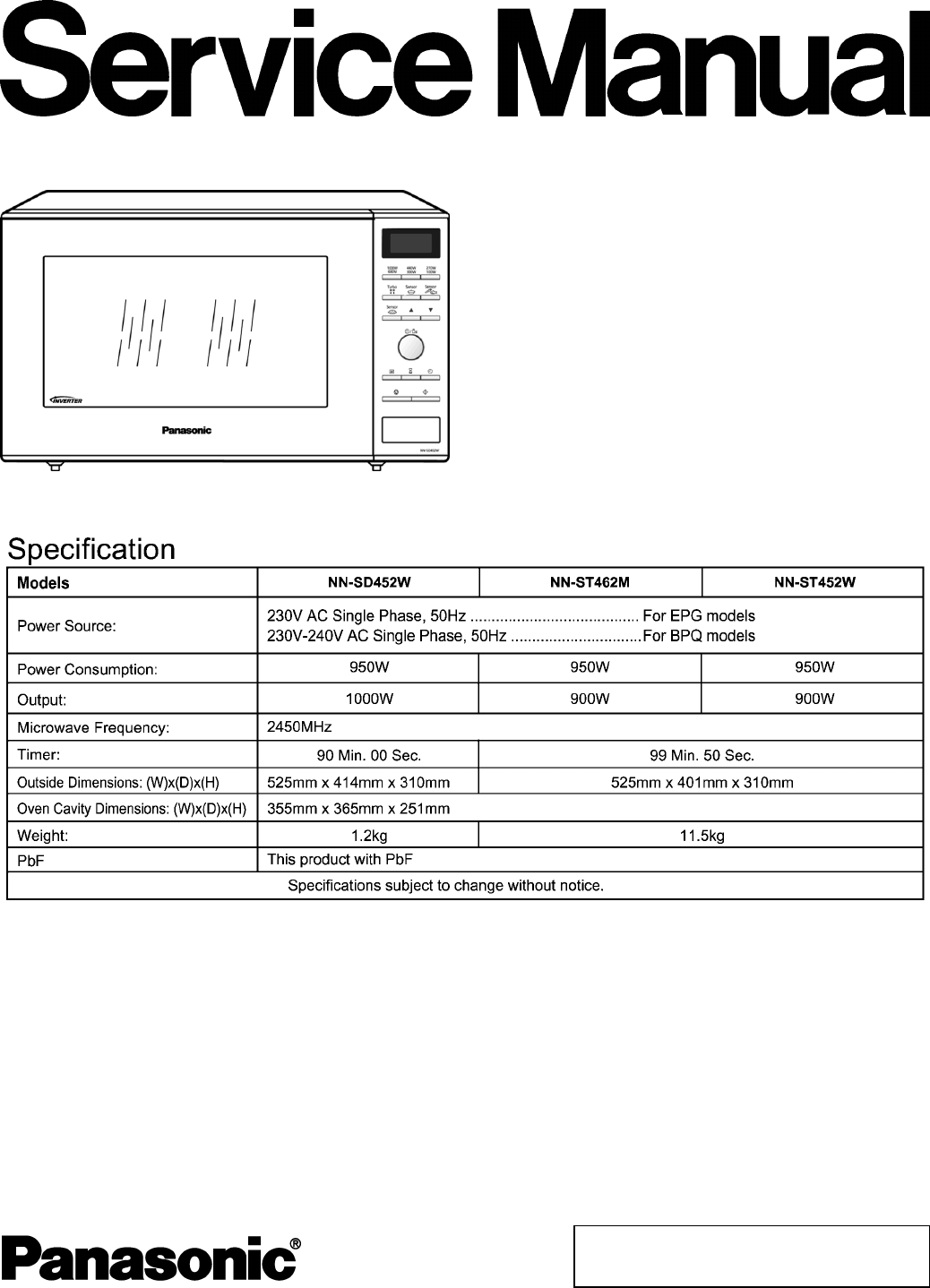
NN-SD452W
NN-ST462M
NN-ST452W
BPQ (U.K.)
EPG (Continental Europe)
Microwave Oven
ORDER NO.PAPMOSH1201015CE
2
NN-SD452W / NN-ST462M / NN-ST452W

3
NN-SD452W / NN-ST462M / NN-ST452W

1 SCHEMATIC DIAGRAM 5
2 DESCRIPTION OF OPERATING SEQUENCE 6
2.1. Variable power cooking control 6
2.2. Inverter power supply circuit 6
2.3. Turbo defrost, Auto cook 6
2.4. Sensor cooking 6
2.5. Steam sensor and digital programmer circuit 7
3 CAUTIONS TO BE OBSERVED WHEN TROUBLESHOOTING
8
3.1. Check the grounding 8
3.2. Inverter warnings 8
3.3. Part replacement. 9
3.4. When the 10A fuse is blown due to the malfunction of the
short switch: 9
3.5. Avoid inserting nails, wire etc. through any holes in the
unit during operation. 9
3.6. Verification after repair 9
3.7. Sharp edges 9
4 DISASSEMBLY AND PARTS REPLACEMENT PROCEDURE
10
4.1. Magnetron 10
4.2. Digital programmer circuit (D.P.C) 10
4.3. Low voltage transformer and/or power relays (RY1, RY2)
11
4.4. Fan motor 11
4.5. Door assembly 11
4.6. Turntable motor 13
4.7. Steam sensor 13
4.8. Inverter power supply 14
5 COMPONENT TEST PROCEDURE 15
5.1. Primary, Secondary Latch Switch interlocks & Power
Relay RY1 15
5.2. Short Switch 15
5.3. Magnetron 15
5.4. key board membrane (Membrane switch assembly) 15
5.5. Inverter power supply (U) 16
5.6. Temperature thermistor 16
6 MEASUREMENTS AND ADJUSTMENTS 17
6.1. Adjustment of primary latch switch, secondary latch switch
and short switch. 17
6.2. Measurement of microwave output 17
7 TROUBLESHOOTING GUIDE 18
7.1. (Troubleshooting) Oven stops operation during cooking
18
7.2. (Troubleshooting) Other problems 19
7.3. Troubleshooting of inverter circuit (U) and magnetron 20
7.4. Simple way of H.V. Inverter/magnetron troubleshooting
21
7.5. How to check the semiconductors using an OHM meter
21
7.6. H.V. INVERTER MAIN PARTS LIST (Z606YBA00QP) 22
8 EXPLODED VIEW AND PARTS LIST 23
8.1. EXPLODED VIEW 23
8.2. PARTS LIST 24
8.3. ESCUTCHEON BASE ASSEMBLY 25
8.4. DOOR ASSEMBLY 27
8.5. WIRING MATERIALS 28
8.6. PACKING AND ACCESSORIES 29
9 DIGITAL PROGRAMMER CIRCUIT 30
9.1. SCHEMATIC DIAGRAM (NN-SD452W) 30
9.2. SCHEMATIC DIAGRAM (NN-ST462M, ST452W) 32
CONTENTS
Page Page
4
NN-SD452W / NN-ST462M / NN-ST452W
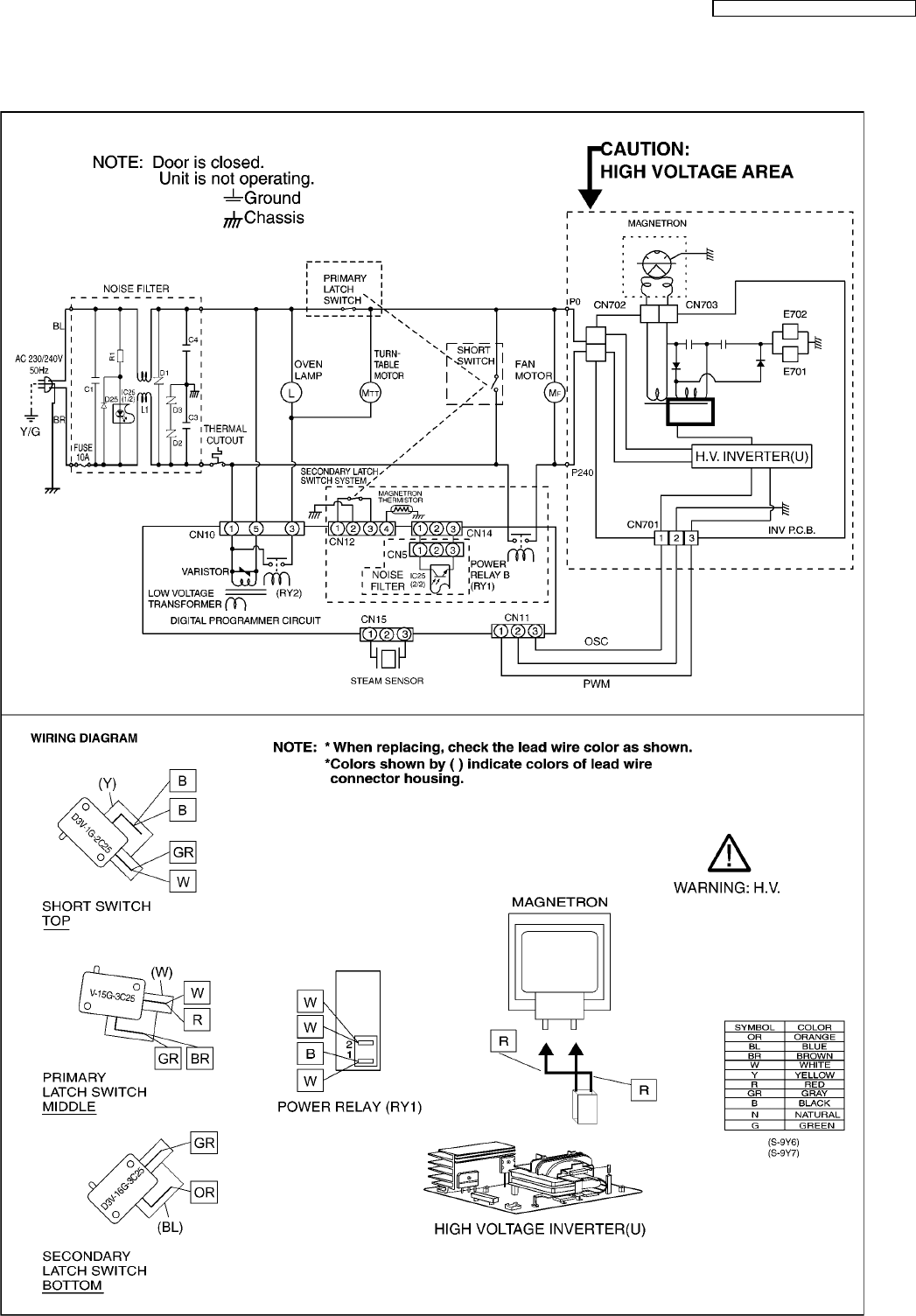
1 SCHEMATIC DIAGRAM
5
NN-SD452W / NN-ST462M / NN-ST452W
2.1. Variable power cooking
control
High Voltage Inverter Power Supply (U) controls output power
by the signal from Digital Programmer Circuit (DPC). Power
relay always stay on, but PWM (Pulse Width Modulation) signal
controls microwave output power.
NOTE:
The ON/OFF time ratio does not correspond with the
percentage of microwave power since approximately 2
seconds are required for heating of magnetron
filament.
Variable Power Cooking
POWER SETTING OUTPUT
POWER(%)
APPROX.
MANUAL MICROWAVE
DUTY
BPQ EPG ON(SEC) OFF(SEC)
TURBO 1000W 100% 22 0
HIGH — 90% 22 0
DEFROST 270W 25% 15 7
MEDIUM 600W 60% 22 0
LOW 440W 45% 22 0
SIMMER 300W 30% 22 0
WARM 100W 10% 8 14
2.2. Inverter power supply circuit
The Inverter Power Supply circuit powered from the line
voltage, 230V 50Hz AC input supplies 4,000V DC to the
magnetron tube, and functions in place of the H.V. transformer,
the H.V. capacitor and H.V. diode.
1. The AC input voltage 230V 50Hz is rectified to DC voltage
immediately.
2. DC voltage will be supplied to the switching devices called
IGBT. These devices are switched ON-OFF by the 20 to 40
kHz PWM (pulse width modulation) signal from the
microcomputer in the DPC.
3. This drives the High voltage transformer to increase voltage
up to 2,000V AC.
4. Then the half-wave doubler voltage rectifier circuit,
consisting of the H.V. diodes and capacitors, generates the
necessary 4,000V DC needed for the magnetron.
5. Output power of the magnetron tube is always monitored by
the signal output from the current transformer built into the
inverter circuit.
6. This signal is fed back to the microcomputer in the DPC to
determine operating conditions and output necessary to
control PWM signal to the Inverter Power Supply for control
of the output power.
2.3. Turbo defrost, Auto cook
When the Auto Control feature is selected and the Start pad is
tapped:
1. The digital programer circuit determines the power level and
cooking time to complete cooking and indicates the
operating state in the display window.
2. When cooking time in the display window has elapsed, the
oven turns off automatically by a control signal from the
digital programmer circuit.
2.4. Sensor cooking
Auto sensor cooking without setting a power level or selecting
a time. All that is necessary is to select an Auto Sensor
Program before starting to cook.
Understanding Auto Sensor Cooking
As the food cooks, a certain amount of steam is produced.
If the food is covered, this steam builds up and eventually
escapes from the container. In Auto Sensor Cooking, a
carefully designed instrument, called the steam sensor
element, senses this escape of steam. Then, based upon
the Auto Sensor Program selected, the unit will
automatically determine the correct power level and the
proper length of time it will take to cook the food.
NOTE:
Auto Sensor Cooking is successful with the foods and
recipes found in the Auto Sensor Cooking Guide.
Because of the vast differences in food composition,
items not mentioned in the Cooking Guide should be
prepared in the microwave oven using power select
and time features. Please consult Variable Power
Microwave Cookbook for procedures.
2 DESCRIPTION OF OPERATING SEQUENCE
6
NN-SD452W / NN-ST462M / NN-ST452W
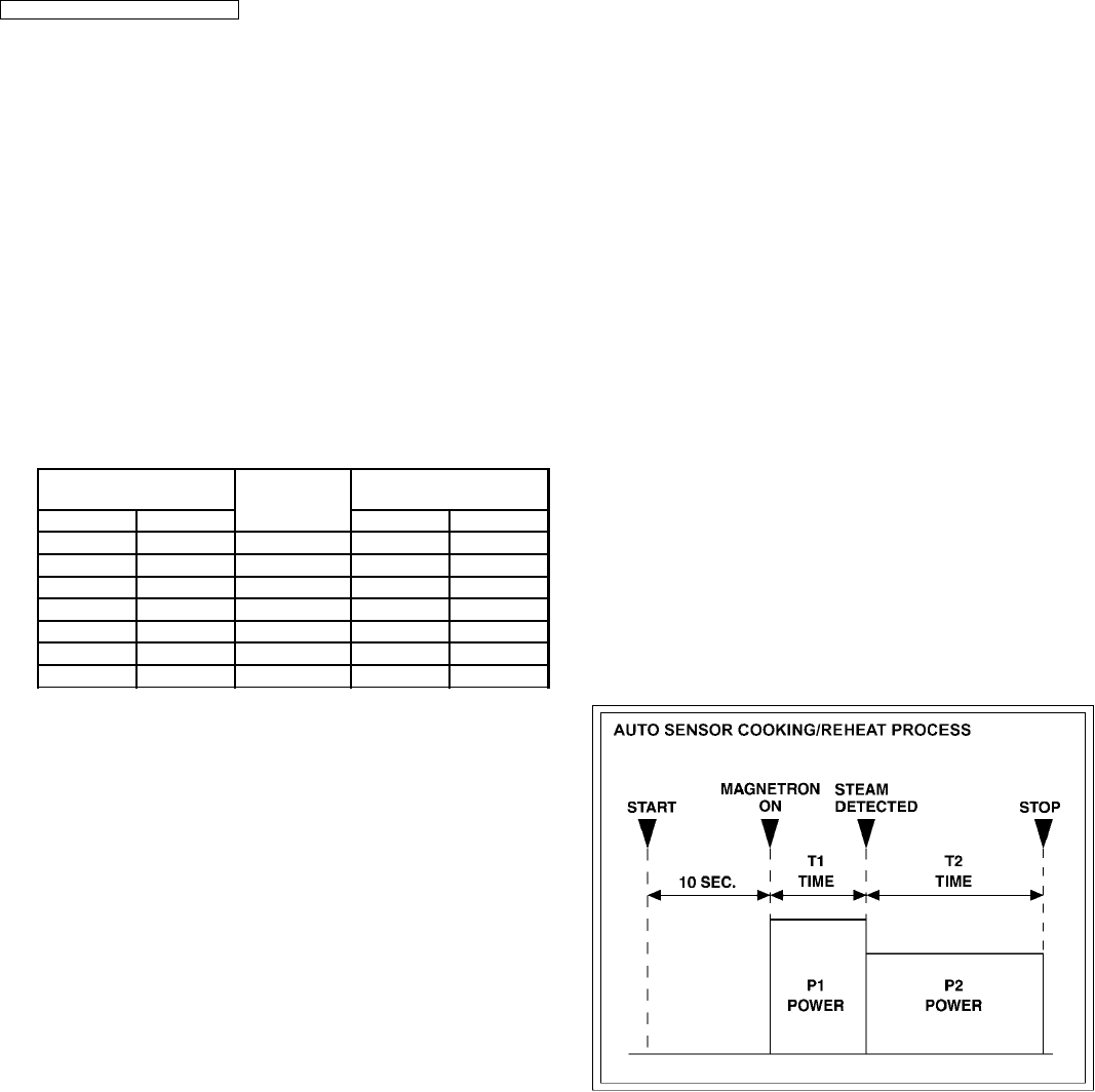
Explanation of the Auto Sensor Cooking process
1. During the first 10 second period there is no microwave
activity. When calculating the T2 time by using the
formula below make sure this 10 seconds is subtracted
from the T1 time. In other words, T1 time starts at the
end of the 10 second period.
2. T1 time The total amount of time it takes the microwave
oven to switch to T2 time after the 10second period.
3. T2 time When the steam escapes from the cooking
container placed in the oven, the steam sensor detects
it and the microprocessor calculates the balance of
cooking time. This T2 time is then shown in the display
and begins counting down.
Balance of cooking time (T2 time)
The balance of cooking time which is called T2 time,
can be calculated by the following formula.
T2 time (in sec.) = T1 time X K factor
NOTE:
Remember, the T1 time starts after the 10 second
period. The coefficient K is programmed into the
microprocessor memory and they are listed in the
following tables along with the P1 and P2 powers.
NOTE:
When "More" or "Less" pad is selected, the K factor
varies resulting in T2 time to be increased or decreased.
Example of calculating the T2 time
Example 1: If the T1 time is measured to be 2 minutes and
40 seconds after the 10 second period.
T2 = T1 × K
= 2 min. and 40 sec. × 0.1
= 160sec. × 0.1
= 16 sec.
Category P1
Power
P2
Power
K Factor
Standard
BPQ Fresh
Vegetable
900W 900W 0.5
EPG 1000W 1000W 0.5
2.5. Steam sensor and digital
programmer circuit
In order to determine if the steam sensor function of the digital
programmer circuit is working, do the following test.
1. Place a water load (150 cc) in the oven.
2. Tap Sensor Reheat pad.
3. Tap Start pad.
4. Steam Sensor detects steam about 1.5 to 4 minutes after
the Start pad is tapped.
5. T1 time cooking automatically switches to remaining time
for cooking (T2).
6. The remaining cooking time (T2) appears in display
window. If the following cooking time appears, Steam
Sensor function is normal.
T1 TIME T2 TIME (Remainingcooking time)
50 Sec. ~ 12 Min. 0 Sec. ~ 10 Min.42 Sec.
7
NN-SD452W / NN-ST462M / NN-ST452W
Unlike many other appliances, the microwave oven is a high
voltage, high current device. It is free from danger in ordinary
use, though extreme care should be taken during repair.
CAUTION
Servicemen should remove their watches & rings whenever
working close to or replacing the magnetron.
3.1. Check the grounding
Do not operate on a two wire extension cord. The microwave
oven is designed to be grounded when used. It is imperative,
therefore, to ensure the appliance is properly grounded before
beginning repair work.
3.2. Inverter warnings
WARNING HIGH VOLTAGE AND HIGHTEMPERATURE
(HOT/LIVE) OF THE INVERTERPOWER SUPPLY (U)
The High Voltage Inverter Power Supply generates very
high voltage and current for the magnetron tube. Though it
is free from danger in ordinary use, extreme care should be
taken during repair.
The aluminum heat sink is also energized with high voltage
(HOT), do not touch when the AC input terminals are
energized. The power device Collector is directly connected
to the aluminum heat sink.
The aluminum heat sink may be HOT due to heat energy,
therefore, extreme care should be taken during servicing.
H.V. Inverter warning
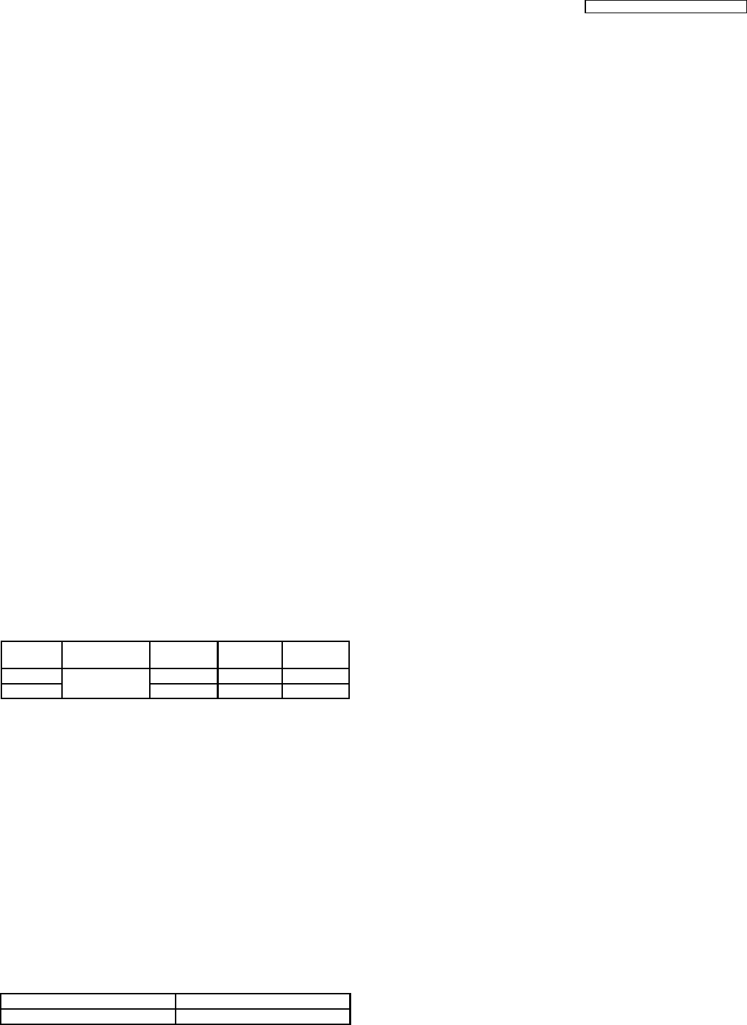
WARNING FOR INVERTER POWER SUPPLY (U)
GROUNDING
Check the High Voltage Inverter Power Supply circuit
grounding. The high voltage inverter power supply circuit
board must have a proper chassis ground. The inverter
grounding plate must be connected to the chassis. If the
inverter board is not grounded it will expose the user to very
high voltages and cause extreme DANGER! Be sure that
the inverter circuit is properly grounded via the inverter
grounding plate.
Grounding of the inverter circuit board
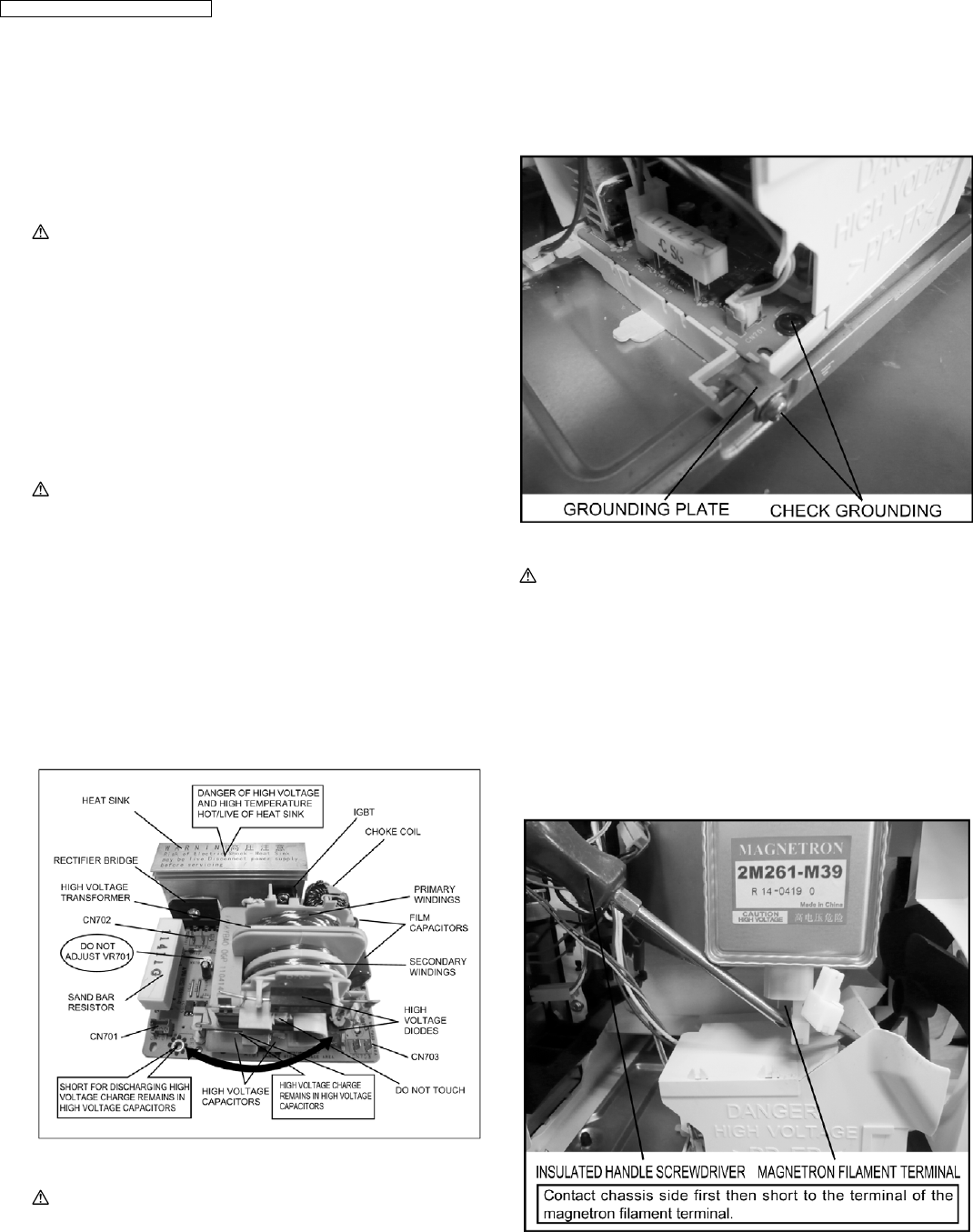
WARNING DISCHARGE THE HIGH VOLATGE
CAPACITORS
For about 30 seconds after the oven is turned off, an
electric charge remains in the high voltage capacitors of the
Inverter Power Supply circuit board.
When replacing or checking parts, remove the power plug
from the outlet and short the inverter output terminal of the
magnetron filament terminals to the chassis ground with an
insulated handle screwdriver to discharge. Please be sure
to contact the chassis ground side first and then short to the
output terminal.
3 CAUTIONS TO BE OBSERVED WHEN
TROUBLESHOOTING
8
NN-SD452W / NN-ST462M / NN-ST452W

Discharging the high voltage capacitors
WARNING
There is high voltage present with high current capabilities
in the circuits of the primary and secondary windings, choke
coil and heat sink of the inverter. It is extremely dangerous
to work on or near these circuits with the oven energized.
DO NOT measure the voltage in the high voltage circuit
including the filament voltage of the magnetron.
WARNING
Never touch any circuit wiring with your hand or with an
insulated tool during operation.
3.3. Part replacement.
When troubleshooting any part or component is to be replaced,
always ensure that the power cord is unplugged from the wall
outlet.
3.4. When the 10A fuse is blown
due to the malfunction of the
short switch:
WARNING
When the 10A 250V fuse is blown due to the malfunction of
the short switch, replace all of the components (primary
latch switch, short switch and power relay RY1).
1. This is mandatory. Refer to “measurements and
adjustments” for the location of these switches.
2. When replacing the fuse, confirm that it has the
appropriate rating for these models.
3. When replacing faulty switches, be sure the mounting
tabs are not bent, broken or deficient in their ability to
hold the switches.
3.5. Avoid inserting nails, wire etc.
through any holes in the unit
during operation.
Never insert a wire, nail or any other metal object through the
lamp holes on the cavity or any holes or gaps, because such
objects may work as an antenna and cause microwave
leakage.
3.6. Verification after repair
1. After repair or replacement of parts, make sure that the
screws of the oven, etc. are neither loosen or missing.
Microwave energy might leak if screws are not properly
tightened.
2. Make sure that all electrical connections are tight before
inserting the plug into the wall outlet.
3. Check for microwave energy leakage.
CAUTION OF MICROWAVE RADIATION LEAKAGE
USE CAUTION NOT TO BECOME EXPOSED TO
RADIATION FROM THE MICROWAVE MAGNETRON OR
OTHER PARTS CONDUCTING MICROWAVE ENERGY.
IMPORTANT NOTICE
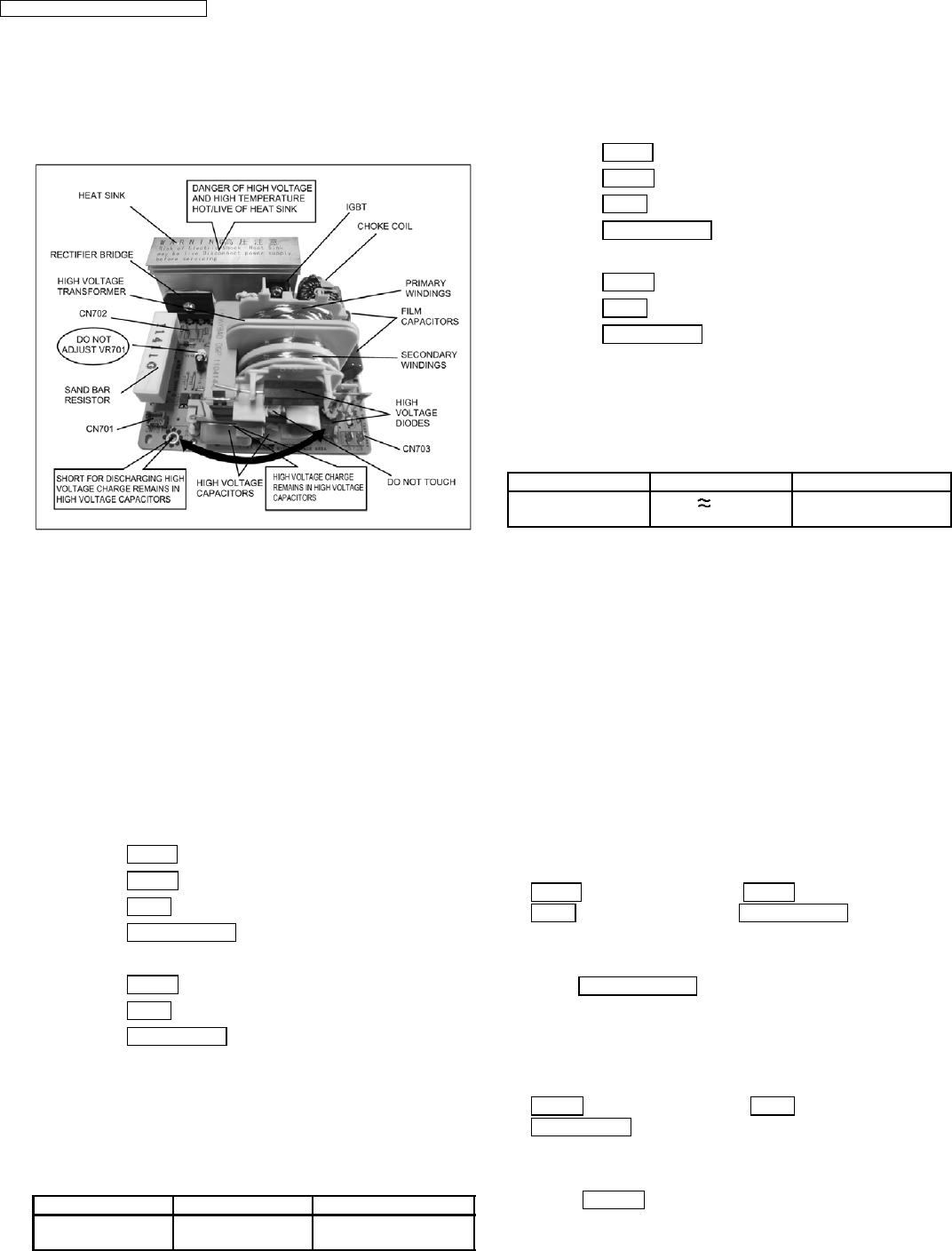
1. The following components have potentials above 2000V
while the appliance is operated.
• Magnetron
• High voltage transformer (Located on inverter (U))
• High voltage diodes (Located on inverter (U))
• High voltage capacitors (Located on inverter (U))
Pay special attention to these areas.
2. When the appliance is operated with the door hinges or
magnetron installed incorrectly, the microwave leakage
can exceed more than 5mW/cm2. After repair or
exchange, it is very important to check if the magnetron
and the door hinges are correctly installed.
3.7. Sharp edges
CAUTION
Please use caution when disassembling or reassembling
internal parts. Some exposed edges may be sharp to the
touch and can cause injury if not handled with care.
9
NN-SD452W / NN-ST462M / NN-ST452W
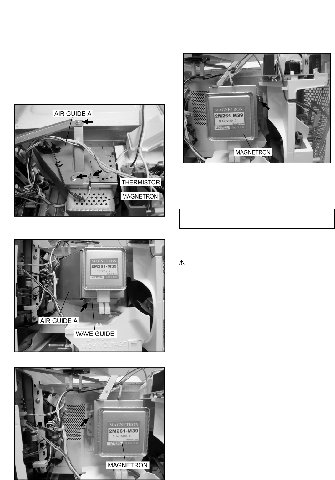
4.1. Magnetron
1. Discharge the high voltage capacitor.
2. Remove 1 screw holding air guide A on the magnetron.
3. Remove 1 screw holding air guide A on cavity top plate.
4. Remove 1 screws holding thermistor on the magnetron.
5. Remove 1 screw holding air guide A on the wave guide,
then remove the air guide A.
6. Remove 4 screws holding the magnetron.
NOTE:
After replacement of the magnetron, tighten mounting
screws properly, making sure there is no gap between
the waveguide and the magnetron to prevent
microwave leakage.
CAUTION
When replacing the magnetron, be sure the antenna gasket is in
place.
4.2. Digital programmer circuit
(D.P.C)
CAUTION:
Be sure to ground any static electric charge built up in
your body before handling the DPC.
1. Disconnect connector CN701 on H.V. Inverter board.
2. Remove 1 screw holding escutcheon base and slide the
escutcheon base upward slightly.
3. Remove all screws holding D.P.C. board on escutcheon
base.
4. Separate D.P.C board from tabs on the escutcheon base
and remove D.P.C board.
To replace membrane key board
5. Use tools such as kinfe etc. to lift the edge of escutcheon
sheet and peel off escutcheon sheet & key board
membrane completely from escutcheon base.
NOTE:
1. The membrane key board is attached to the
escutcheon base with double faced adhesive tape.
Therefore, applying hot air such as using a hair
dryer is recommended for smoother removal.
2. When installing the new key board membrane, make
sure that the surface of escutcheon base is clean to
prevent a malfunction or shorted contacts.
4 DISASSEMBLY AND PARTS REPLACEMENT
PROCEDURE
10
NN-SD452W / NN-ST462M / NN-ST452W
4.3. Low voltage transformer
and/or power relays (RY1,
RY2)
CAUTION:
Be sure to ground any static electric charge built up in
your body before handling the DPC.
1. Replace D.P.C. board.
(A) Using solder wick or a desoldering tool and 30W
soldering iron carefully remove all solder from the terminal
pins of the low voltage transformer and/or power relays.
CAUTION:
Do not use a soldering iron or desoldering tool of
more than 30 watts on D.P.C. contacts.
(B) With all the terminal pins cleaned and separated from
D.P.C. contacts, remove the defective transformer/power
relays, Replace components making sure all terminal pins
are inserted completely resolder all terminal contacts
carefully.
4.4. Fan motor
1. Disconnect 2 lead wires from fan motor terminals.
2. Remove 2 screws at location on oven attaching orifice
assembly.
3. Remove orifice assembly from oven assembly.
4. Remove fan blade from the fan motor shaft by pulling it
straight out.
5. Remove 2 screws holding fan motor to orifice.
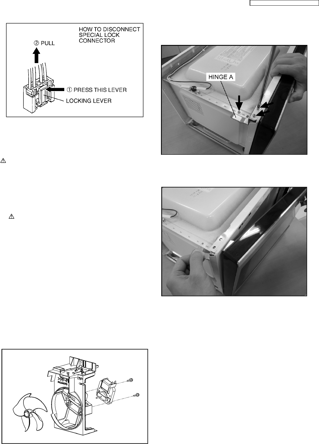
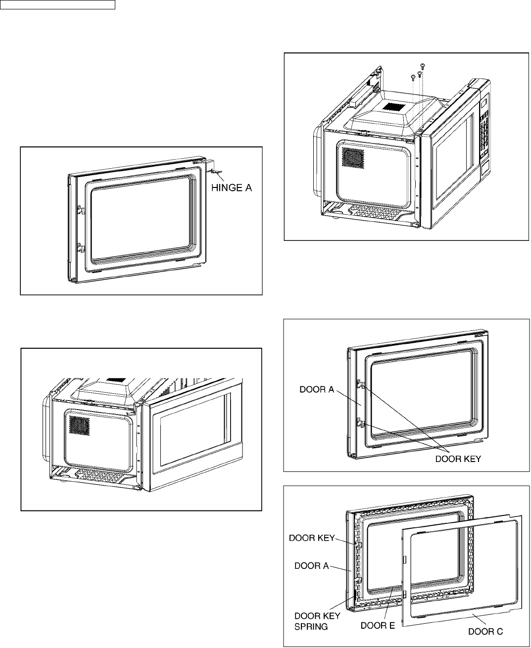
4.5. Door assembly
1. Support the door, remove 3 screws holding hinge A.
2. Open the door, remove door(U) and hinge A from cavity.
NOTE:
Support the door before opening.
3. Remove door C from door A (U) & door E by carefully
pulling outward starting from upper right hand corner using
a flat blade screwdriver.
4. Separate door E from tabs on door A (U) and remove door
A (U).
5. Remove door key and door key spring from door E.
11
NN-SD452W / NN-ST462M / NN-ST452W
6. Replace other components.
To re-install components:
NOTE:
After replacement of the defective component parts
of the door, reassemble it properly and adjustment
so as to prevent an excessive microwave leakage.
Adjustment of the door assembly (Refer page 17).
7. Place the hole of hinge A into the door’s upper hinge pin.
8. Use your left index finger to support the door’s lower hinge
pin while guiding the door’s hinge A into the cavity slot.
Then lower your finger to seat the door onto the hinge.
NOTE:
Door alignment is crucial. If door is misaligned,
apply pressure until alignment is achieved.
NOTE:
Adjust so that the upper portion of the door will
touch firmly to the oven cavity front plate, without
pushing the door. If the door assembly is not
mounted properly, microwave power may leak from
the clearance between the door and oven.
9. Tighten 2 mounting screws.
Be sure the gap between door E and cavity front plate will
be 0.3~0.7mm.
NOTE:
Always perform the microwave leakage measurement
test after installation and adjustment of door assembly.
12
NN-SD452W / NN-ST462M / NN-ST452W
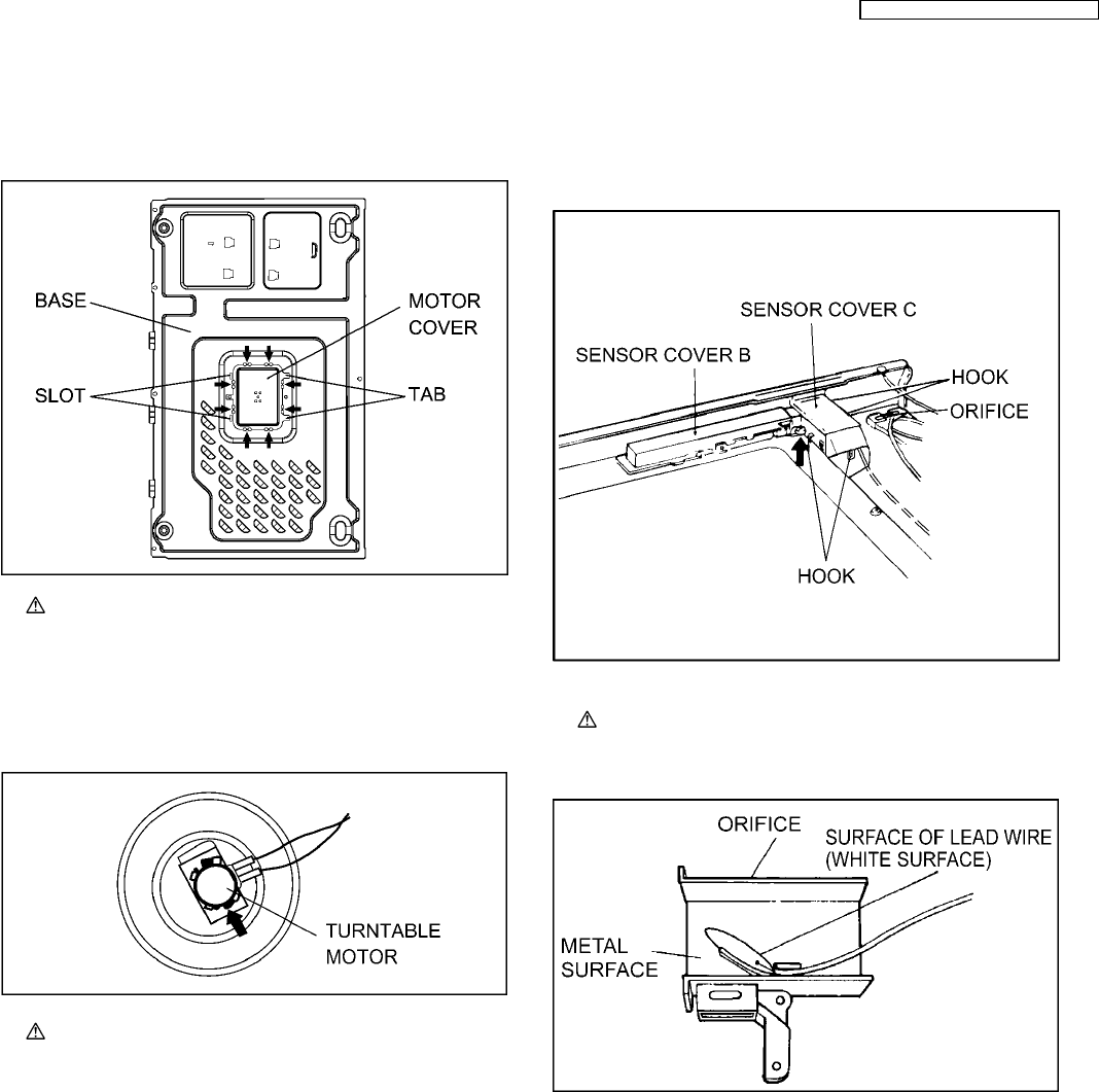
4.6. Turntable motor
1. Remove the motor cover by breaking off at the 8 spots
indicated by arrows with a cutter or the like.
NOTE:
After removing the motor cover, be sure that cut
portions are properly trimmed or bent to the inside
so that no sharp edges will be exposed to outside.
2. Disconnect 2 lead wires connected to the turntable motor.
3. Remove the turntable motor by removing screw.
NOTE:
After reinstalling the new turntable motor and
reconnecting the 2 lead wires, reinstall the motor
cover by rotating it around 180, tucking the 2 tabs
under the base in the 2 provided slots, then screw
the single tab to the base using a 4mm × 6mm
screw.
4.7. Steam sensor
1. Disconnect connector CN2 from digital programmer circuit
board.
2. Disengage catch hooks on sensor cover C from orifice.
3. Remove steam sensor from orifice.
NOTE:
When installing the steam sensor, make sure that
the direction of steam sensor is as shown in figure.
13
NN-SD452W / NN-ST462M / NN-ST452W
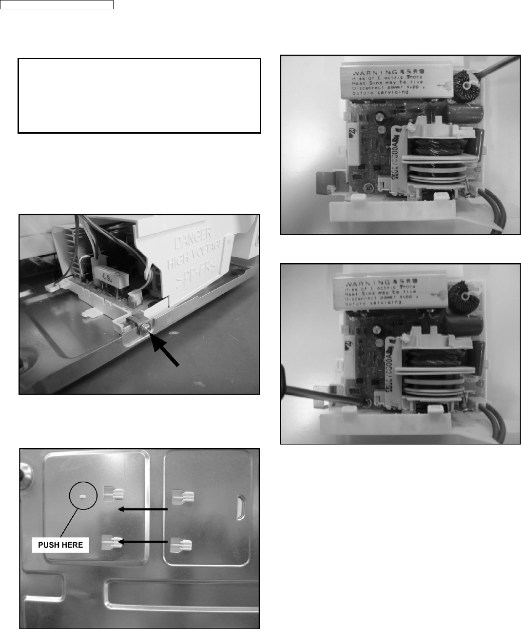
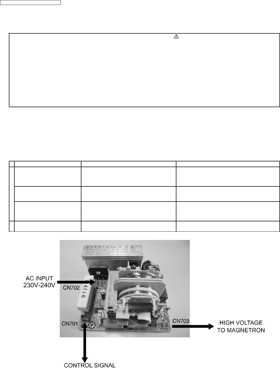
4.8. Inverter power supply
CAUTIONS
1. Always leave the grounding plate in place.
2. Always securely tighten the ground screw through the bottom of the
chassis (base).
3. Securely connect 3 lead wire connectors.
4. Make sure the heat sink has enough space (gap) from the oven.
Take special care not to dress any lead wire over the aluminum heat
sink because it is hot.
1. Discharge high voltage charge.
2. Remove the H.V.lead wire from magnetron terminals.
3. Disconnect 2 connectors from CN701 & CN702 on
H.V.Inverter(U).
4. Remove 1 screw holding grounding plate to the base.
5. Press 1 encircled locking tab and then slide 4 locking tabs
of Inverter bracket at the bottom of the base in direction of
arrows.
6. Remove 1 screw holding H.V.Inverter to Inverter bracket.
7. Remove 1 screw holding grounding plate to H.V. Inverter.
8. Seperate H.V. Inverter from Inverter bracket by freeing 3
catch hooks on the Inverter bracket.
14
NN-SD452W / NN-ST462M / NN-ST452W
WARNING
1. High voltage is present at the output terminals of the High Voltage
Inverter (U) including aluminum heat sink during any cook cycle.
2. It is neither necessary nor advisable to attempt measurement of the
high voltage.
3. Before touching any oven components, or wiring, always unplug
the power cord and discharge the high voltage capacitors (see page
8).
5.1. Primary, Secondary Latch
Switch interlocks & Power
Relay RY1
1. Unplug lead connectors to Power Relay RY1 and verify
open circuit of the Power Relay RY1 1-2 terminals.
2. Unplug lead connectors to Primary Latch Switch and
Secondary Latch Switch.
3. Test the continuity of switches at door opened and closed
positions with ohm meter (low scale).
Normal continuity readings should be as follows.
Door Closed Door Opened
Primary Latch Switch 0
Ω
(Close)
Ω
(Open)
Secondary Latch Switch 0
Ω
(Close)
Ω
(Open)
Power Relay RY1
Ω
(Open)
Ω
(Open)
5.2. Short Switch
1. Unplug lead wires from Inverter Power Supply (U) primary
terminals.
2. Connect test probes of ohm meter to the disconnected
leads that were connected to Inverter Power Supply (U).
3. Test the continuity of short switch with door opened and
closed positions using lowest scale of the ohm meter.
Normal continuity readings should be as follows.
Door Opened Door Closed
0Ω(Close) Ω(Open)
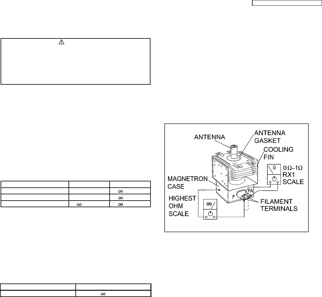
5.3. Magnetron
Continuity checks can only indicate an open filament or a
shorted magnetron. To diagnose for an open filament or
shorted magnetron.
1. Isolate magnetron from the circuit by disconnecting the
leads.
2. A continuity check across magnetron filament terminals
should indicate one ohm or less.
3. A continuity check between each filament terminal and
magnetron case should read open.
5.4. key board membrane
(Membrane switch assembly)
Check continuity between switch terminals, by tapping an
appropriate pad on the key board. The contacts assignment of
the respective pads on the key board is as shown in digital
programmer circuit.
5 COMPONENT TEST PROCEDURE
15
NN-SD452W / NN-ST462M / NN-ST452W
5.5. Inverter power supply (U)
DO NOT try to REPAIR H.V. Inverter power supply
(U).Replace complete H.V. Inverter(U) Unit.
WARNING: HIGH VOLTAGE
Test if failure codes H95, H97 or H98 appear when performing
the following procedure. It is recommended to use an AC line
input current ammeter for testing.
Test 1
1. With the oven unit’s AC power supply cord is unplugged
from the wall outlet, unplug the 2 pin H.V. connector CN703
from the magnetron tube.
2. Place 1 liter of water load into oven cavity.
3. Plug in the oven’s AC power supply cord into outlet.
4. Program DPC.
For SD452W model
a. Press Clock button once.
b. Press Timer button once.
c. Press Start button once.
d. Press 1000W/600W button once.
For ST462M & ST452W models
a. Press Timer pad twice.
b. Press Start pad once.
c. Press Micro Power pad once.
5. Program oven at High power for 1 minute and press [Start]
pad.
a. After approximately 23 seconds, oven stops operating.
b. During oven operation, the input current is
approximately 0.5 to 1A. If both a and b are OK,
proceed to test 2.
INPUT CURRENT FAILURE CODE
Unplug CN703 0.5 to 1A Oven stops in 23
seconds after started.
Test 2
Continued from Test 1
1. Unplug the oven’s AC power supply cord from outlet.
2. Unplug 3 pin connector CN701. CN703 remains unplugged.
3. Plug in the oven’s AC power supply cord into outlet.
4. Program DPC.
For SD452W model
a. Press Clock button once.
b. Press Timer button once.
c. Press Start button once.
d. Press 1000W/600W button once.
For ST462M & ST452W models
a. Press Timer pad twice.
b. Press Start pad once.
c. Press Micro Power pad once.
5. Program oven at High power for 1 minute and press [Start]
pad.
a. After approximately 3 seconds, oven stops operating.
b. During oven operation, the input current is
approximately 0.4A.
INPUT CURRENT FAILURE CODE
Unplug CN701 0.4A Oven stops in 3
seconds after started.
If both a and b check OK, the Inverter Power Supply (U) can be
determined to be OK.
5.6. Temperature thermistor
The thermistor that is attached to the magnetron detects the
temperature of the magnetron and will stop magnetron
operation when overheating is detected. A normal thermistor´s
resistance is 35KΩto 110KΩfor an ambient temperature range
of 10-30 degree C.
If the resistance reading is out of the range stated here, the
thermistor is detective and must be replaced.
It is also possible to display thermistor level by taking the
following steps.
For SD452W model
1. Program the DPC into TEST MODE (Plug-in oven →press
Clock button once →press Timer button once →press
Start button once →press 1000W/600W button once).
2. Program oven at Standing Time for 1 minute and press
[Start] button.
3. Press Sensor Reheat once, the thermistor level reading
will shown on the display.
The normal reading should be in the range of 16-230.
For ST462M & ST452W models
1. Program the DPC into TEST MODE (Plug-in oven →press
Timer pad twice →press Start pad once →press
Micro Power pad once).
2. Program oven at Standing Time for 1 minute and press
[Start] pad.
3. Press Reheat twice, the thermistor level reading will
shown on the display.
The normal reading should be in the range of 16-230.
16
NN-SD452W / NN-ST462M / NN-ST452W
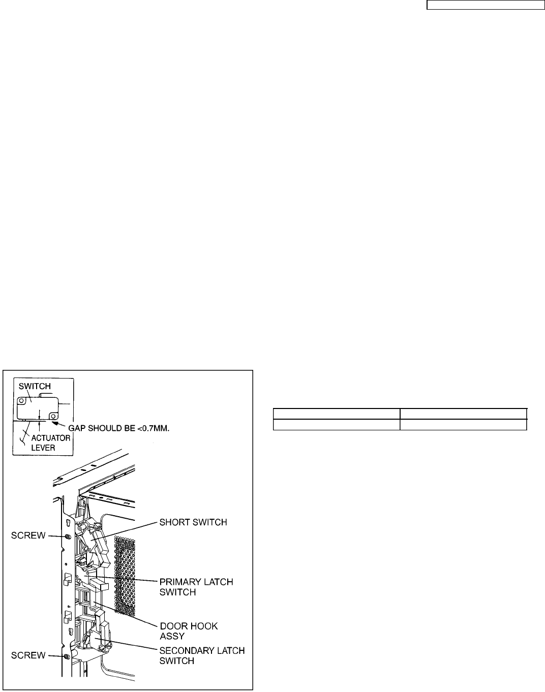
6.1. Adjustment of primary latch
switch, secondary latch switch
and short switch.
1. Mount the Primary latch switch, the Secondary latch switch
and the Short switch to the door hook assembly as shown
in illustration.
NOTE:
No specific individual adjustments during
installation of the Primary latch switch, Secondary
latch switch or Short switch to the door hook are
required.
2. When mounting the door hook assembly to the oven
assembly, adjust the door hook assembly by moving it in
the direction of the arrows in the illustration so that the oven
door will not have any play in it. Check for play in the door
by pulling the door assembly. Make sure that the latch keys
move smoothly after adjustment is completed. Completely
tighten the screws holding the door hook assembly to the
oven assembly.
3. Reconnect the short switch and check the continuity of the
monitor circuit and all latch switches again by following the
component test procedures.
6.2. Measurement of microwave
output
The output power of the magnetron can be determined by
performing IEC standard test procedures. However,due to the
complexity of IEC test procedures, it is recommended to test
the magnetron using the simple method outlined below.
Necessary Equipment:
• 1 liter beaker
• Glass thermometer
• Wrist watch or stopwatch
NOTE:
Check the line voltage under load. Low voltage will
lower the magnetron output. Take the temperature
readings and heating time as accurately as possible.
1. Fill the beaker with exactly one liter of tap water.Stir the
water using the thermometer and record the water’s
temperature. (recorded as T1).
2. Place the beaker on the center of glass tray.
Set the oven for High power and heat it for exactly one
minute.
3. Stir the water again and read the temperature of the water.
(recorded as T2).
4. The normal temperature rise at High power level for each
model is as shown in table.
TABLE (1L-1min. test)
RATED OUTPUT TEMPERATURE RISE
1000W Min. 8.5°C
6 MEASUREMENTS AND ADJUSTMENTS
17
NN-SD452W / NN-ST462M / NN-ST452W
7 TROUBLESHOOTING GUIDE
DANGER: HIGH VOLTAGES
1. DO NOT RE-ADJUST PRESET CONTROL on the H.V.Inverter (U). It is very dangerous to repair or adjust without proper test equipment
because this circuit generates very large current and high voltage. Operating a misaligned inverter circuit is dangerous.
2. Ensure proper grounding before troubleshooting.
3. Be careful of the high voltage circuitry, taking necessary precautions when troubleshooting.
4. Discharge high voltage remaining in the H.V.Inverter (U).
5. When checking the continuity of the switches or the H.V.Inverter, disconnect one lead wire from these parts and then check continuity with the
AC plug removed. Doing otherwise may result in a false reading or damage to your meter. When disconnecting a plastic connector from a
terminal, you must hold the plastic connector instead of the lead wire and then disconnect it, otherwise lead wire may be damaged or the
connector cannot be removed.
6. Do not touch any parts of the circuitry on the digital programmer circuit, since static electric discharge may damage this control panel. Always
touch ground while working on this panel to discharge any static charge in your body.
7. 230-240V AC is present on the digital programmer circuit (Terminals of power relay’s and primary circuit of Digital Programmer Circuit). When
troubleshooting, be cautious of possible electrical shock hazard.
Before troubleshooting, operate the microwave oven following the correct operating procedures in the instruction manual in order
to find the exact cause of any trouble, since operator error may be mistaken for the oven’s malfunction.
7.1. (Troubleshooting) Oven stops operation during cooking
SYMPTOM CAUSE CORRECTIONS
1.
.
Oven stops in 3 seconds after
pressing [Start] button.
No input AC is supplied to H.V.Inverter (U)
CN702 terminals
1. Latch Switch
2. Power relay RY1
3. Loose lead wire connector CN701, CN702
4. H.V. Inverter (U)
Oven stops in 23 seconds after
pressing [Start] button.
H.V.Inverter (U) operates by the control signals
from DPC but magnetron is not oscillating
1. Magnetron
2. Loose lead wire connector CN703
3. H.V. Inverter (U)
Oven stops in 10 seconds after
pressing [Start] button.
(Auto sensor cooking)
Steam sensor circuit is not functioning 1. Steam sensor
2. DPC
3. Open or loose wiring of sensor terminal from
connector CN2 on DPC
2. No display and no operation at all.
Fuse is blown.
Most probably loose connection of connectors, or
door latch mechanism is not adjusted properly
1. Align door, Door Latch Switches
2. Loose wiring connectors
18
NN-SD452W / NN-ST462M / NN-ST452W

7.2. (Troubleshooting) Other problems
SYMPTOM CAUSE CORRECTIONS
1. Oven is dead. 1. Open or loose lead wire harness
Fuse is OK. 2. Open thermal cutout / thermistor Check thermal cutout is defective.
No display and no operation at all. 3. Open low voltage transformer
4. Defective DPC
2. No display and no operation at all.
Fuse is blown.
1. Shorted lead wire harness Check adjustment of primary, secondary latch
switch and short switch including door.
2. Defective primary latch switch (NOTE 1)
3. Defective short switch (NOTE 1)
4. Defective Inverter Power Supply (U)
NOTE 1:
All of these switches must be replaced at the same time.
Check continuity of power relay RY1 contacts (between 1 and 2) and if it has continuity, replace
power relay RY1 also.
3. Oven does not accept key input
(Program)
1. Key input is not in proper sequence Refer to operation procedure.
2. Open or loose connection of membrane key
button to DPC (Flat cable)
3. Shorted or open membrane key board
4. Defective DPC Refer to DPC troubleshooting.
4. Fan motor turns on when oven is
plugged in with door closed.
1. Misadjustment or loose wiring of secondary
latch switch
Adjust door and latch switches.
2. Defective secondary latch switch
3. Door switch CN12
5. Timer starts count down but no
microwave oscillation.
(No heat while oven lamp and fan
motor turn on)
1. Off-alignment of primary latch switch Adjust door and latch switches.
2. Open or loose connection of high voltage
circuit especially magnetron filament circuit
NOTE:
Large contact resistance will cause lower
magnetron filament voltage and cause
magnetron to have lower output and/or be
intermittent.
3. Defective high voltage component
H.V. Inverter Power Supply (U)
Magnetron
Check high voltage component according to
component test procedure and replace if it is
defective.
4. Open or loose wiring of power relay RY1
5. Defective primary latch switch
6. Defective DPC or power relay RY1 Refer to DPC troubleshooting
6. Oven can program but timer does not
start countdown.
1. Open or loose wiring of secondary latch switch
2. Off-alignment of secondary latch switch
3. Defective secondary latch switch
7. Microwave output is low. Oven takes
longer time to cook food.
1. Decrease in power source voltage Consult electrician
2. Open or loose wiring of magnetron filament
circuit.(Intermittent oscillation)
3. Aging change of magnetron
8. Fan motor turns on and turntable
motor rotates when door is opened.
1. Low voltage transformer on DPC.
9. Oven does not operate and return to
plugged in mode as soon as [Start]
button is pressed.
1. Defective DPC Check grounding connector on escutcheon
base.
10. Loud buzzing noise can be heard. 1. Loose fan and fan motor
11. Oven stops operation during cooking. 1. Open or loose wiring of primary and
secondary latch switch
Adjust door and latch switches.
2. Operation of thermal cutout
19
NN-SD452W / NN-ST462M / NN-ST452W
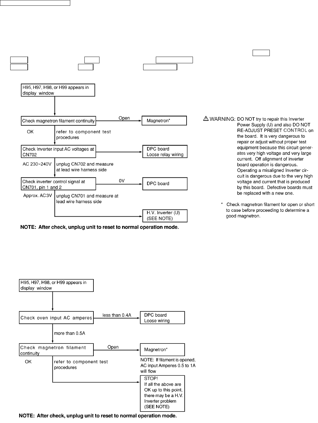
7.3. Troubleshooting of inverter circuit (U) and magnetron
This oven is programmed with a self diagnostics failure code system which will help for troubleshooting. H95, H97, H98 and H99
are the provided failure codes to indicate magnetron and inverter circuit problem areas. This section explains failure codes of H95,
H97, H98 and H99. First, you must program the DPC into TEST MODE, For SD452W model: press Clock button once →press
Timer button once →press Start button once →press 1000W/600W button once, For ST462M & ST452W model: press
Timer pad twice →press Start pad once →press Micro Power pad once. Program unit for operation. H95, H97, H98, H99
appears in display window a short time after [Start] pad is pressed and there is no microwave oscillation.
Alternate way to troubleshoot oven with AC Ampere meter used
H95, H97, H98, H99 appears in display window a short time after [Start] button is pressed and no microwave oscillation with AC
Ampere meter used for troubleshooting.
20
NN-SD452W / NN-ST462M / NN-ST452W
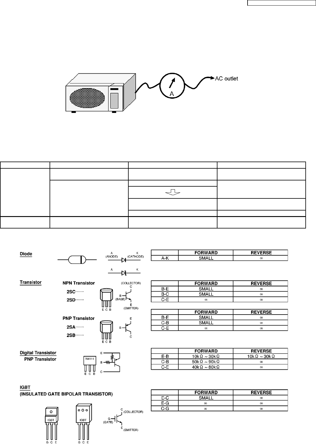
7.4. Simple way of H.V. Inverter/magnetron troubleshooting
Purpose:
Simple way (3/23 seconds rule) of identifying whether it’s Magnetron, Inverter, or others.
Set-up:
The unit under question is connected through the Ammeter as shown below.
Procedure:
Follow the matrix table below to identify the problem source.
Note:
Do not replace both Inverter board and Magnetron simultaneously and automatically without going through this
procedure.
Power will: Ammeter reading is: To do: Remedy:
Shut off in 23 seconds
after “Start”.
1. Between 0.5A and 1.0A. Check and repair open magnetron circuit Open magnetron wiring between Inverter
and magnetron terminal.
2. Between 1.0A and 2.0A. Check continuity of D702 in Inverter PCB.
1. D702 shorted Replace H.V.Inverter
(Z606YBA00QP)
2. D702 is OK Replace magnetron
Shut off in 3 seconds
after “Start”
1. Less than 0.5A Check open circuit: Latch Switch, DPC,
Power Relay and CN701
Replace defective component(s), or
correct switch, cables and connectors.
7.5. How to check the semiconductors using an OHM meter
21
NN-SD452W / NN-ST462M / NN-ST452W

7.6. H.V. INVERTER MAIN PARTS LIST (Z606YBA00QP)
Ref. No. Part No. Part Name & Description Pcs/Set Remarks
Q701 Z1JAEV000003 IGBT 1
C701 ZCWHC3B104JA FILM CAPACITOR 1 0.1µF,1000VDC
C702 ZCWF4305N851 FILM CAPACITOR 1 3µF,250VDC
DB701 Z0FBBQ000006 RECTIFIER BRIDGE 1
L701 Z5020W100AP CHOKE COIL 1
R702 Z0CM562JA002 SAND BAR RESISTOR 1
T701 Z609ABA00GP TRANSFORMER 1 (INCLUDING D701,D702,C706,C707)
D701,D702 Z0FBAZ000003 DIODE 2
C706 Z0C3F562A002 FILM CAPACITOR 1 5600PF/3KV
C707 Z0C3F822A002 FILM CAPACITOR 1 8200PF/3KV
22
NN-SD452W / NN-ST462M / NN-ST452W
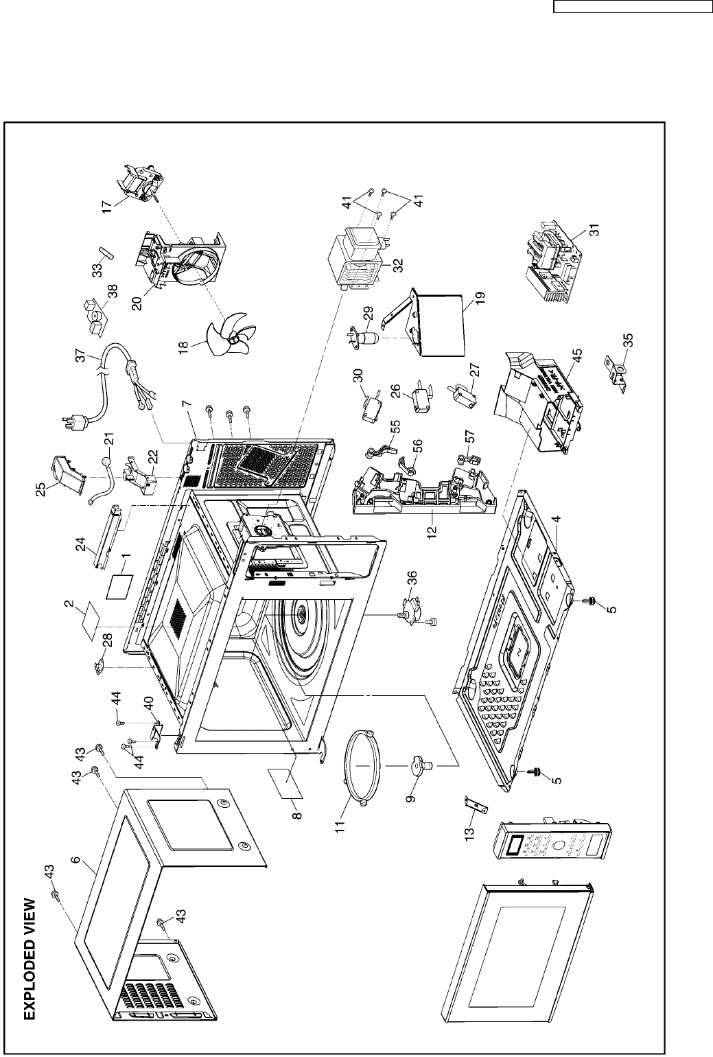
8 EXPLODED VIEW AND PARTS LIST
8.1. EXPLODED VIEW
23
NN-SD452W / NN-ST462M / NN-ST452W
8.2. PARTS LIST
NOTE:
1. When ordering replacement part(s), please use part number(s) shown in this part list.
Do not use description of the part.
2. Important safety notice:
Components identified by mark have special characteristics important for safety.
When replacing any of these components, use only manufacture’s specified parts.
Ref. No. Part No. Part Name & Description Pcs/Set Remarks
1 Z00064080BP CAUTION LABEL 1 BPQ
1 Z00069000EP CAUTION LABEL 1 EPG
2 Z21559Y10QP OVEN STICKY PAPER 1
4 Z10019Y00AP BASE 1
5 Z10089W40HPS RUBBER FOOT 2
6 Z10099Y00SAP CABINET BODY (U) 1 ST462M
6 Z10099Y00HAP CABINET BODY (U) 1 SD452W,ST452W
7 Z200A9Y00SQP OVEN (U) 1
8 Z20559Y00AP COVER 1
9 Z21319Y00AP PULLY SHAFT 1
11 Z290D6W50XP ROLLER RING (U) 1
12 Z30209X70EP DOOR HOOK 1
13 Z11619Y00AP REINFORCEMENT BRACKET 1
17 Z400A9Y00QP FAN MOTOR 1
18 Z40089Y00AP FAN BLADE 1
19 Z40259Y00AP AIR GUIDE A 1
20 Z41449Y10QP ORIFICE 1
21 Z607S4T00AP STEAM SENSOR 1
22 Z64499Y00AP SENSOR COVER A 1
24 Z64508660AP SENSOR COVER B 1
25 Z65439Y00AP SENSOR COVER C 1
26 Z61425U30XN MICRO SWITCH 1 (PRIMARY LATCH SWITCH)
27 Z61415U30XN MICRO SWITCH 1 (SECONDARY LATCH SWITCH)
28 Z61459V00XP THERMAL CUTOUT 1
29 Z612E9C30BP INCANDESCENT LAMP (U) 1
30 Z61785U30XN MICRO SWITCH 1 (SHORT SWITCH)
31 Z606YBA00QP H.V.INVERTER (U) 1
32 Z2M261-M39R MAGNETRON 1
33 Z62309W40HP FUSE 1 (10A)
35 Z66629Y00AP GROUNDING PLATE 1
36 Z63266S30XP TURNTABLE MOTOR 1
37 Z900C9Y10KT AC CORD W/PLUG 1 BPQ
37 Z900C9Y10PT AC CORD W/PLUG 1 EPG
38 Z607X9Y60BP NOISE FILTER 1
40 Z30069Y00AP HINGE A 1
41 ZTWFL4+12T SCREW 4 FOR MAGNETRON
43 ZTWFA4+12D SCREW 4 FOR CABINET BODY
44 ZTWFA4+12LR SCREW 3 FOR HINGE A
45 Z65859Y00AP INVERTER BRACKET 1
55 Z31389X70EP HOOK LEVER C 1
56 Z31369X70EP HOOK LEVER A 1
57 Z31379X70EP HOOK LEVER B 1
24
NN-SD452W / NN-ST462M / NN-ST452W
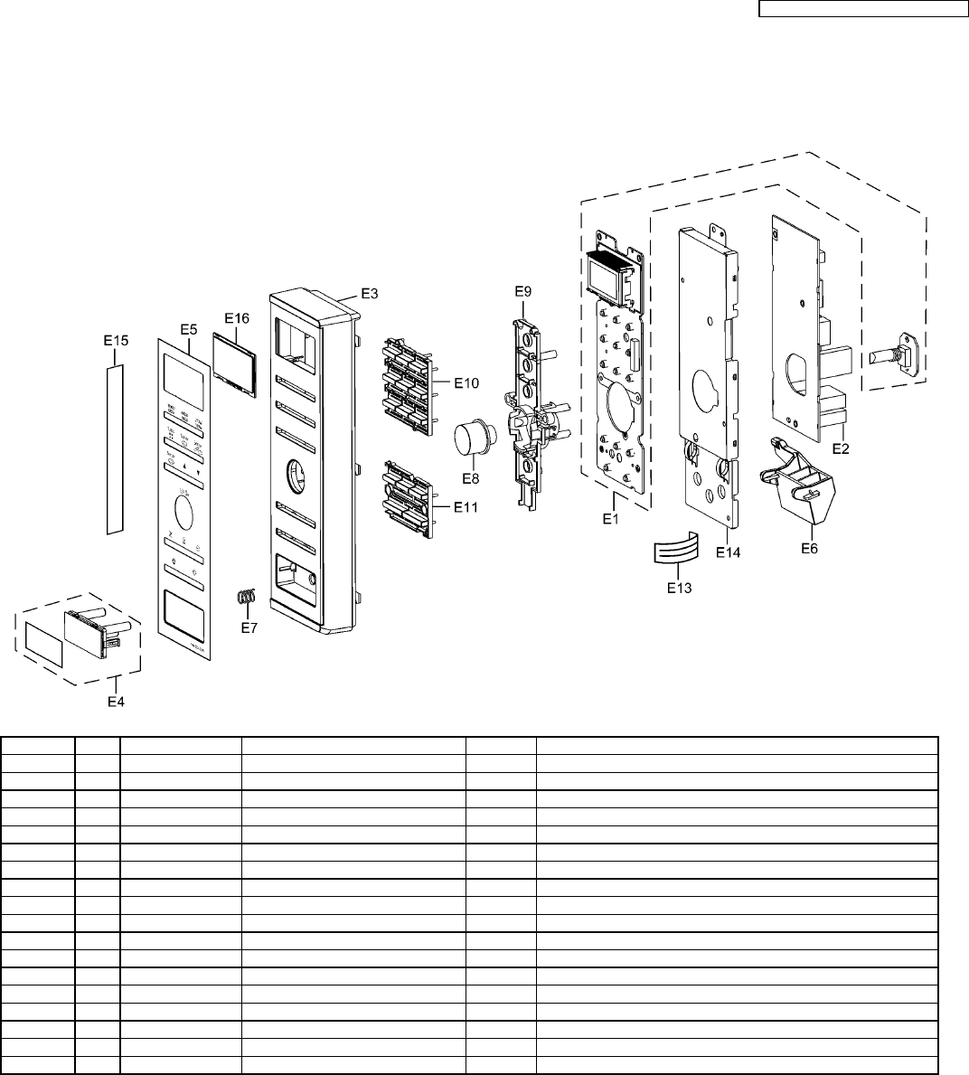
8.3. ESCUTCHEON BASE ASSEMBLY
8.3.1. NN-SD452W
Ref. No. Part No. Part Name & Description Pcs/Set Remarks
E1 Z603L9Y70EP D.P.CIRCUIT (AU) 1 SD452W EPG
E2 Z603Y9Y70EP D.P.CIRCUIT (DU) 1 SD452W EPG
E3 Z80349Y70HEP ESCUTCHEON BASE 1 SD452W EPG
E4 Z891P9Y00HAP DOOR OPENING BUTTON (U) 1 SD452W EPG
E5 Z83379Y70HEP MEMBRANE SHEET 1 SD452W EPG
E6 Z82569Y00AP DOOR OPENING LEVER 1
E7 Z80375K00AP COOK BUTTON SPRING 1
E8 Z803G9M60HBP POP-OUT DIAL (U) 1 SD452W EPG
E9 Z80189Y40AP DIAL SUPPORT 1 SD452W EPG
E10 Z82989Y40HAP BUTTON 1 SD452W EPG
E11 Z82989Y90HAP BUTTON B 1 SD452W EPG
E13 Z66167D00AP FLAT CABLE 1 SD452W EPG
E14 Z81279Y40AP BACK PANEL 1 SD452W EPG
E15 Z00079Y70HEP NAME PLATE 1 SD452W EPG
E16 Z81269Y70BEP DISPLAY WINDOW 1 SD452W EPG
25
NN-SD452W / NN-ST462M / NN-ST452W
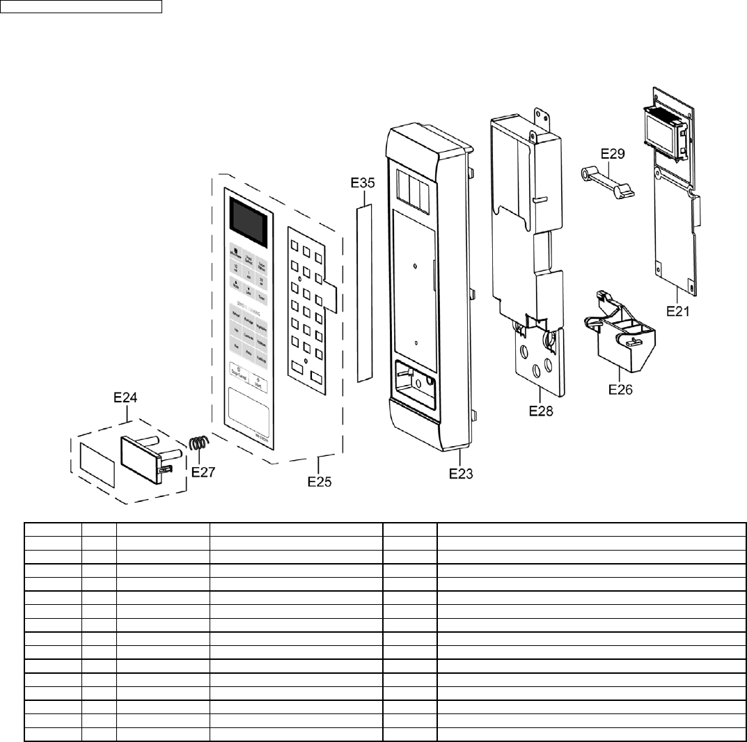
8.3.2. NN-ST462M, ST452W
Ref. No. Part No. Part Name & Description Pcs/Set Remarks
E21 Z603L9Y60BP D.P.CIRCUIT (AU) 1 ST462M BPQ,ST452W BPQ
E23 Z80349Y10SHP ESCUTCHEON BASE 1 ST462M BPQ
E23 Z80349Y10HAP ESCUTCHEON BASE 1 ST452W BPQ
E24 Z891P9Y60SBP DOOR OPENING BUTTON (U) 1 ST462M BPQ
E24 Z891P9Y00HAP DOOR OPENING BUTTON (U) 1 ST452W BPQ
E25 Z630Y9Y60SBP MEMBRANE SWITCH (U) 1 ST462M BPQ
E25 Z630Y9Y60HBP MEMBRANE SWITCH (U) 1 ST452W BPQ
E26 Z82569Y00AP DOOR OPENING LEVER 1
E27 Z80375K00AP COOK BUTTON SPRING 1
E28 Z81279Y00AP BACK PANEL 1 ST462M BPQ,ST452W BPQ
E29 Z66139Y20AP BACKSTOP 1 ST462M BPQ,ST452W BPQ
E35 Z00079Y60SBP NAME PLATE 1 ST462M BPQ
E35 Z00079Y60HBP NAME PLATE 1 ST452W BPQ
26
NN-SD452W / NN-ST462M / NN-ST452W
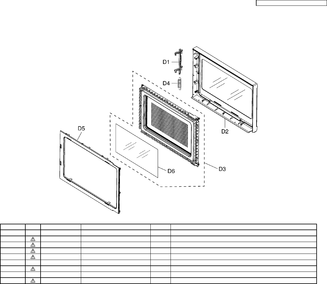
8.4. DOOR ASSEMBLY
Ref. No. Part No. Part Name & Description Pcs/Set Remarks
D1 Z30189Y00AP DOOR KEY A 1
D2 Z302A9Y70HEP DOOR A (U) 1 SD452W EPG
D2 Z302A9Y60SBP DOOR A (U) 1 ST462M BPQ
D2 Z302A9Y60HBP DOOR A (U) 1 ST452W BPQ
D3 Z302K9Y00AP DOOR E (U) 1
D4 Z30215G10XN DOOR KEY SPRING 1
D5 Z30859Y00AP DOOR C 1
D6 Z31459Y00AP DOOR SCREEN A 1
27
NN-SD452W / NN-ST462M / NN-ST452W
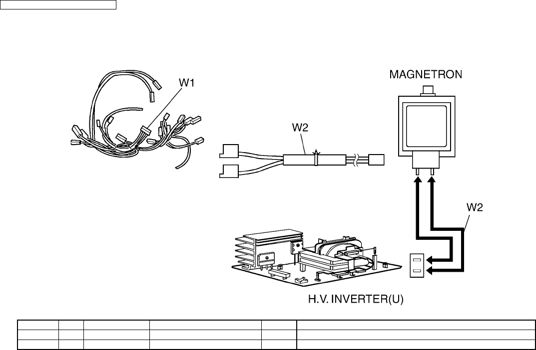
8.5. WIRING MATERIALS
Ref. No. Part No. Part Name & Description Pcs/Set Remarks
W1 Z030A9Y60BP LEAD WIRE HARNESS 1 (INCLUDING MAGNETRON THERMISTOR)
W2 Z030E9Y10QP H.V.LEAD WIRE 1
28
NN-SD452W / NN-ST462M / NN-ST452W
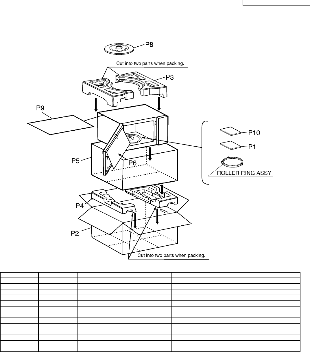
8.6. PACKING AND ACCESSORIES
Ref. No. Part No. Part Name & Description Pcs/Set Remarks
P1 Z00039Y60BP INSTRUCTION MANUAL 1 ST462M BPQ,ST452W BPQ
P1 Z00039Y70EP INSTRUCTION MANUAL 1 SD452W EPG
P2 Z01029Y70HEP PACKING CASE,PAPER 1 SD452W EPG
P2 Z01029Y60SBP PACKING CASE,PAPER 1 ST462M BPQ
P2 Z01029Y60HBP PACKING CASE,PAPER 1 ST452W BPQ
P3 Z01049Y00AP UPPER FILLER 1
P4 Z01059Y00AP LOWER FILLER 1
P5 Z01068100XN P.E.BAG 1
P6 Z01078J00XN DOOR SHEET 1
P8 Z06014N30BP COOKING TRAY 1
P9 Z01099Y00AP SHEET 1 ST462M BPQ
P10 Z000B9Y70EP COOK BOOK 1 EPQ
29
NN-SD452W / NN-ST462M / NN-ST452W
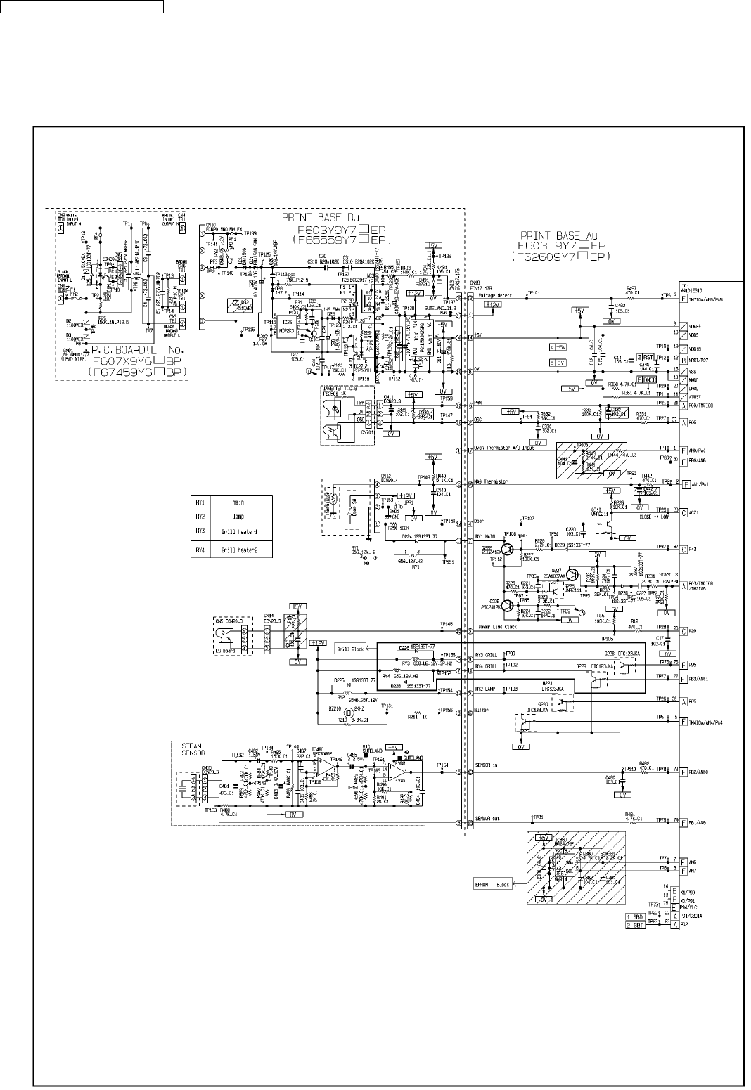
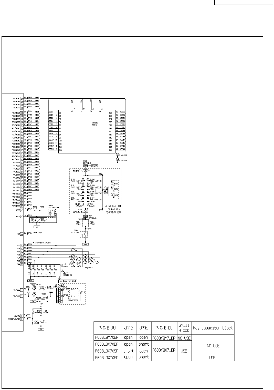
9 DIGITAL PROGRAMMER CIRCUIT
9.1. SCHEMATIC DIAGRAM (NN-SD452W)
30
NN-SD452W / NN-ST462M / NN-ST452W
31
NN-SD452W / NN-ST462M / NN-ST452W
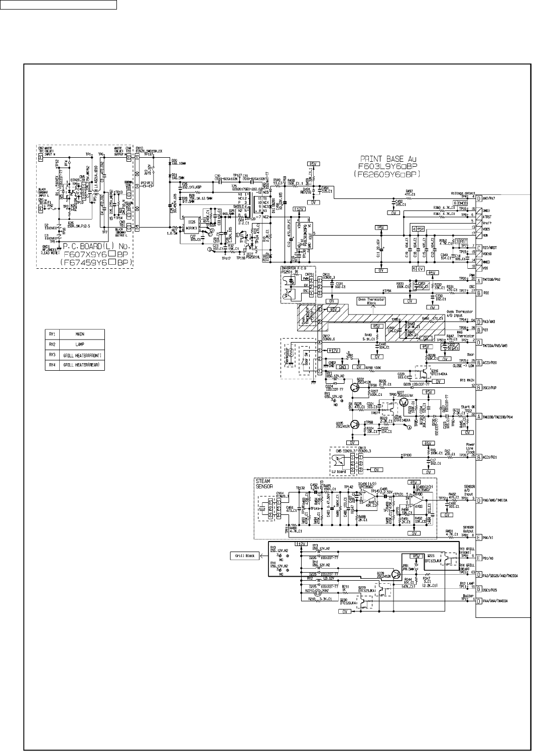
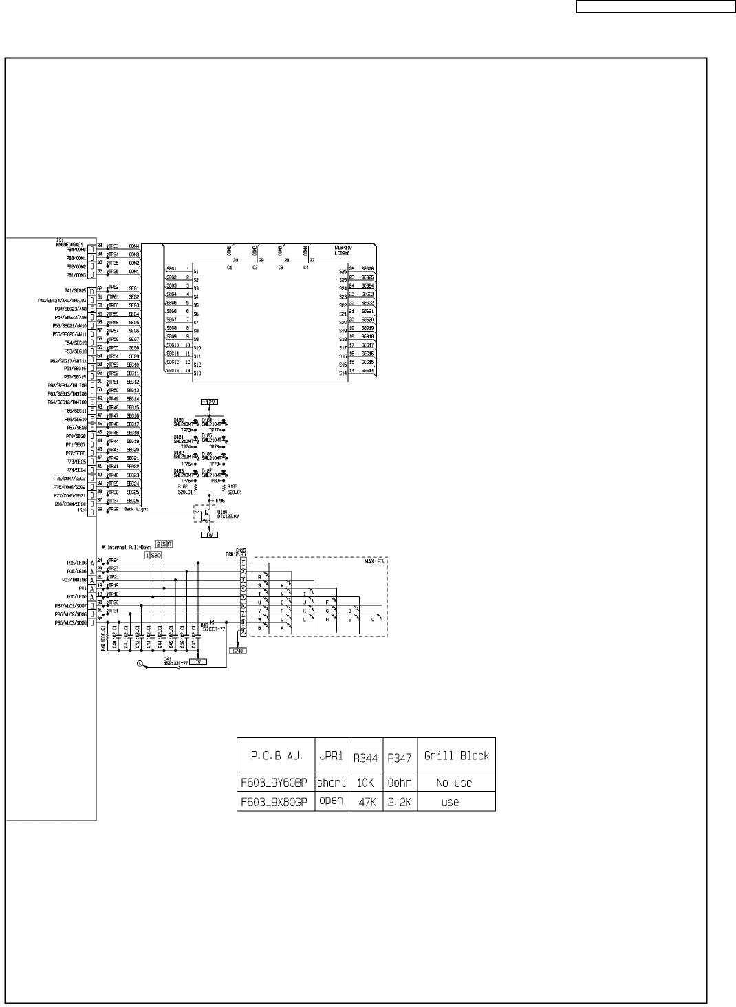
9.2. SCHEMATIC DIAGRAM (NN-ST462M, ST452W)
32
NN-SD452W / NN-ST462M / NN-ST452W
33
NN-SD452W / NN-ST462M / NN-ST452W
01/12
S-9Y6, S-9Y7
Printed in China
