Panasonic Arbitrator 360 Operating Instructions
2015-05-18
: Panasonic Panasonic-Arbitrator-360-Operating-Instructions-731250 panasonic-arbitrator-360-operating-instructions-731250 panasonic pdf
Open the PDF directly: View PDF ![]() .
.
Page Count: 147 [warning: Documents this large are best viewed by clicking the View PDF Link!]
- Cover
- Contents
- Overview
- Installing/Uninstalling
- Description of the Screen Displays
- Operations
- Administrator Setup
- Indicator Lamps and Recorder Status
- Setup
- Error Messages
- Camera Connection and Combination of Cameras
- Service Logs
- Software License Agreement

Operating Instructions
1009K0 -M
ENGLISH
VQT2C61
Front-End Application
Model No. AG-JJLFE20P
• Microsoft and the Microsoft logo, Windows are registered trademarks or trademarks of
Microsoft Corporation in the United States and other countries.
Exporting from the Front-End Application and Streaming are not available at present. Upgrading is scheduled for the future.
In this manual, each explanation for Exporting from the Front-End Application and Streaming is
enclosed in a colored frame, like .
This manual includes the information for the AG-CPD10CRUP/AG-CPD15P, but this application
does not support that at present.

Contents
Exporting from the Front-End Application is not
available at present. Upgrading is scheduled for
the future.
Overview ............................................. 4
Operating Environment ........................................... 6
Installing/Uninstalling ........................ 7
Installing .................................................................. 7
Preparations ........................................................ 7
Installing the Front-End application ..................... 7
Remote updating ................................................. 8
Uninstalling .............................................................. 9
Procedures for Windows XP ............................... 9
Procedures for Windows Vista ............................ 9
Description of the Screen Displays ...10
Main Screen .......................................................... 10
Toolbar ....................................................................11
Video Display Section ............................................ 14
Live Operation Section .......................................... 15
Playback Section ................................................... 18
Property Section .................................................... 20
Info tab .............................................................. 20
Ofcers tab ........................................................ 21
Status tab .......................................................... 21
Snapshot tab ..................................................... 22
Bookmark tab (only in Archive mode) ................ 22
Classify/Case tab (only in Archive mode) .......... 23
Upload Screen ....................................................... 24
Export Screen ........................................................ 25
DVD Burn Screen .................................................. 26
Restore Screen (Provided Only with the
AG-CPD15P and AG-CPD10CRUP) ..................... 27
Cong Screen ........................................................ 28
Admin Password screen .................................... 28
Allocation (Video/Audio) screen ........................ 29
Camera1 screen ................................................ 31
Date/Time screen .............................................. 33
File Transfer screen ........................................... 34
Network screen ................................................. 35
Operation screen ............................................... 38
Embedded OSD screen .................................... 39
Radar/GPS screen ............................................ 40
Rec/Play screen ................................................ 42
Registration screen ........................................... 45
Service screen ................................................... 47
Triggers screen .................................................. 48
Operations ........................................ 49
Startup and Termination ........................................ 49
Starting up ......................................................... 49
Restarting .......................................................... 50
Terminating ........................................................ 50
Switching and Adjusting Display Mode .................. 51
Switching Full/Simple Operation mode ............. 51
Switching the QVGA and VGA sizes ................. 52
Switching the Main video and Sub video ........... 53
Switching Day and Night modes ....................... 54
Adjusting image brightness ............................... 55
Viewing a Live Video ............................................. 56
Zooming in live mode ........................................ 56
Making a backlit image easier to view ............... 56
Making a dark image easier to view .................. 57
Checking audio .................................................. 57
Compensating image brightness ....................... 58
Recording .............................................................. 59
Starting and stopping recording ........................ 59
Zooming in record mode ................................... 60
Focusing ............................................................ 60
Adjusting image brightness in record mode ...... 61
Turning off the [REC] lamp of the color camera
during recording ................................................ 61
Turning audio recording On or Off ..................... 62
LPR setting ........................................................ 62
Adding bookmarks in record mode .................... 63
Creating a snapshot picture in record mode ..... 64
Playback in Archive Mode ..................................... 65
Playback ............................................................ 65
Skip playback .................................................... 66
Fast rewind, fast forward, and slow playback .... 67
Quick replay ...................................................... 68
Turning playback sound On or Off ..................... 68
Creating classify information ............................. 69
Adding bookmarks in archive mode .................. 69
Creating a snapshot picture in archive mode .... 70
Displaying Information ........................................... 71
Meta Information (Info) ...................................... 71
Ofcer information (
Ofcers
) ....................................71
Status information (Status) ................................ 72
Snapshot information ........................................ 72
Bookmark information ....................................... 73
Classify information (Classify/Case) .................. 73
Uploading Files ...................................................... 74
Automatic uploading .......................................... 74
Exporting Files ....................................................... 75
Creating a DVD ..................................................... 76
Restoring a File ..................................................... 78

Contents (continued)
Exporting from the Front-End Application and
Streaming are not available at present. Upgrading
is scheduled for the future.
Administrator Setup ........................ 79
Basic Operations for the Administrator Setup
Screen ................................................................... 79
Opening the Administrator Setup screen ........... 79
Setting of items .................................................. 79
Allocation (Video/Audio) ........................................ 80
Resolution/RecordRate ..................................... 80
Connection Camera .......................................... 80
Preset Settings .................................................. 81
Audio In Select .................................................. 82
Init Audio Rec after power ON (Allocation) ........ 82
Camera1 ................................................................ 83
Camera1 ............................................................ 83
Init Camera1 Settings after power ON ............. 84
Date/Time .............................................................. 86
File Transfer .......................................................... 87
Upload ............................................................... 87
Export/DVD Burn ............................................... 87
Certication ....................................................... 88
Folder ................................................................ 88
Network ................................................................. 89
Streaming .......................................................... 89
Recorder (PC LAN) ........................................... 89
Recorder (USB WIRELESS LAN) ..................... 90
Recorder (UPLOAD LAN) ................................. 91
Operation ............................................................... 92
Synchronize Time .............................................. 92
Version Up ......................................................... 92
Format ............................................................... 93
Delete All Files ................................................... 94
Clear Ofcer Information ................................... 94
Factory Default .................................................. 95
Setting Copy ...................................................... 95
Setting Retrieval ................................................ 96
Service Log ....................................................... 96
Embedded OSD .................................................... 97
Embedded OSD ................................................ 97
Embedded OSD Item ........................................ 97
Radar/GPS ............................................................ 98
Radar ................................................................. 98
GPS ................................................................... 99
Rec Start Information ...................................... 100
Rec/Play .............................................................. 101
Rec .................................................................. 101
GPO ................................................................ 102
Auto Power OFF .............................................. 103
Init Settings after power ON (Rec/Play) .......... 103
Classify ............................................................ 104
Storage Capacity Warning............................... 104
Registration ......................................................... 105
Meta Denition ................................................ 105
User Settings ................................................... 108
Limited Operation ............................................ 108
Service ................................................................ 109
Triggers ................................................................110
Trigger ..............................................................110
Trigger1-Trigger16 ............................................110
Indicator Lamps and Recorder
Status ...............................................112
Setup ................................................113
Admin Password ..............................................113
Allocation (Video/Audio) setup .........................113
Camera1 setup .................................................117
Date/Time setup ...............................................119
File Transfer setup ........................................... 120
Network setup ................................................. 121
Embedded OSD setup .................................... 122
Radar/GPS setup ............................................ 123
Rec/Play setup ................................................ 124
Registration setup ........................................... 126
Triggers setup .................................................. 127
Error Messages .............................. 128
Messages Common to the Memory Card Video
Recorder .............................................................. 128
Messages Unique to the Front-End Application ... 134
Camera Connection and Combination
of Cameras ..................................... 141
Service Logs ................................... 142
Contents .............................................................. 142
Format of Service Log ......................................... 145
Software License Agreement ........ 146
■ Display in this manual
Display on the screen may differ from the actual
product.
Overview
AG-JJLFE20P Front-End Application for the Memory
Card Video Recorder (hereinafter called "this
application") is a Windows application for controlling the
AG-CPD20P/AG-CPD15P/AG-CPD10CRUP Memory
Card Video Recorder.
This application enables the following operations, which
are also operable with the remote control panel (sold
separately).
Viewing a Live Video
Video signals from a camera connected to the Memory
Card Video Recorder can be viewed on the screen. A
color camera connected to the [CAMERA 1] connector
of the Memory Card Video Recorder can be controlled
with this application.
Recording video and audio
Video from the cameras and sound from the
microphones connected to the Memory Card Video
Recorder can be recorded in the SDHC Memory Cards
loaded in the recorder.
Simultaneous display and recording of
video signals from the cameras
Pictures captured by the cameras connected to the
Memory Card Video Recorder are displayed on a Main
and/or Sub windows and are recorded. A maximum of
6 cameras can be connected to the Memory Card
Video Recorder.
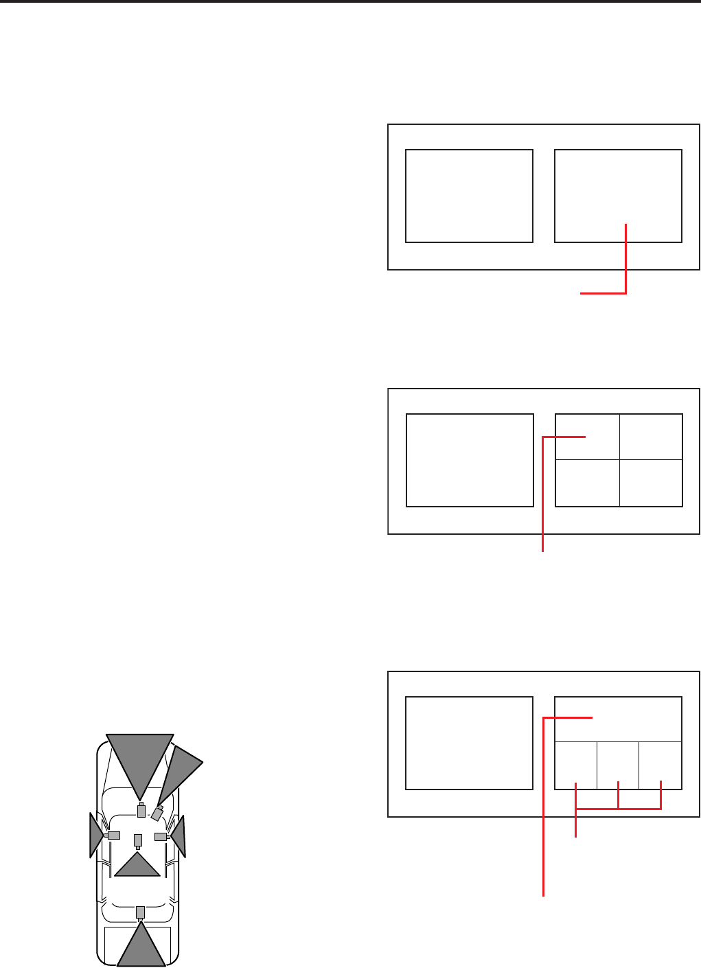
• Main window
: A picture of a camera selected from
among CAMERA 1, 2, and 3.
• Sub window
: A picture or combined pictures from
a camera or cameras as follows:
-A picture from a camera selected from among
CAMERA 2, and 3
-Combined four pictures (one selected from among
CAMERA 1, 2, and 3, and three from CAMERA 4, 5,
and 6 in QUAD or PANORAMA size)
Example: When 6 cameras are connected
Front
(CAMERA 1) LPR
(CAMERA 3)
R
(CAMERA 5)
L
(CAMERA 4)
Back
(CAMERA 6)
R-Seat
(CAMERA 2)
When the mirror (reversed image) function is provided
with CAMERAs 4, 5, and 6, enable this function. If this
function is not provided, connect the R-side camera to
CAMERA 4 and the L-side camera to CAMERA 5.
Main window Sub window (one picture)
Selected from among
CAMERA 2, and 3
Main window
Sub window
(four pictures, QUAD)
Selected from among
CAMERA 1, 2, and 3
CAMERA
6
CAMERA
4
CAMERA
5
Selected from among
CAMERA 2, and 3
(Upper and lower parts of a
picture is cut by 1/6)
Pictures from three
cameras are reduced
to 1/9.
Main window
Sub window
(four pictures, PANORAMA)
CAMERA
4
CAMERA
6
CAMERA
5

Overview (continued)
Playing back recorded video and audio
It is possible to play back video and audio recorded
in the SDHC Memory Cards that are loaded in the
Memory Card Video Recorder.
Uploading data for the Memory Card Video
Recorder
It is possible to upload data recorded in the SDHC
Memory Cards that are loaded in the Memory
Card Video Recorder to the Back-End server. Meta
information and bookmark information are also
uploaded. Uploaded data are deleted from the SDHC
Memory Cards.
Exporting data
Data recorded in the SDHC Memory Cards that are
loaded in the Memory Card Video Recorder can be
exported for external media, such as the hard disk of
a PC or a USB memory device. Exported data can be
deleted from the SDHC Memory Cards.
Creating a DVD
It is possible to export data recorded in the SDHC
Memory Cards that are loaded in the Memory Card
Video Recorder in DVD-Video format. Meta information
can be embedded in the data to be exported. Exported
data can be deleted from the SDHC Memory Cards.
Conguration for the administrator
Settings for operation of the Memory Card Video
Recorder can be performed.
Exporting from the Front-End Application is not
available at present. Upgrading is scheduled for
the future.

Overview (continued)
Operating Environment
A PC that meets the following operating environment
is required for user of this application.
CPU: Intel Core Duo 1.66 GHz or more
(recommended)
RAM: 512 MB or more (for Windows Vista
Business, 1 GB or more) (recommended)
Display: 1024×768 dot or more
LAN: 1000BASE-T/100BASE-TX
OS: Windows XP Professional Service Pack 3 or
later, Windows Vista Business Service Pack 2 or
later
Add on: .Net Framework 3.5 Service Pack 1
Windows Installer3.1
Adobe Reader 8 or 9
Notes
When live videos from the recorder is being displayed
(streaming) or a stored video le is being played using
this application, frames may be dropped or sound may
be broken up, depending on the PC status.
If security software is running together with this
application, the operation of this application may
slow down or the connection with the recorder may
be released. Such phenomena may be improved
by changing the settings of Firewall of the security
software.
While copying data to a DVD using this application,
never do the following operations:
- Turning off the power of the PC and peripheral
devices.
- Running another application.
- Starting the utility for system maintenance.
- Connecting or disconnecting peripheral devices.
- Moving the PC
- Imparting vibration or shock to the PC
- For a notebook PC, avoid supplying power with a
battery (For supplying power with a battery, be sure to
fully charge the battery.)
- Changing the power setting of PC
•
•
•
Streaming is not available at present. Upgrading
is scheduled for the future.
Installing/Uninstalling
Installing
The Front-End application is installed with the
following procedures. For installing the application,
WindowsInstaller V3.1 and .Net Framework 3.5 Service
Pack 1 must be installed on the computer.
Preparations
1. Download "WindowsInstaller V3.1" from
the Microsoft download site.
If the WindowsInstaller has been installed, update
it.
2. Install the "WindowsInstaller V3.1" by
following the instructions.
3. Download "Microsoft .NET Framework
3.5 Service Pack 1" from the Microsoft
download site.
If .Net3.5 has been installed, update it.
4. Install the "Microsoft .NET Framework
3.5 Service Pack 1" by following the
instructions.
Installing the Front-End application
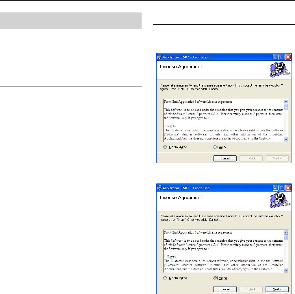
1. Click on FESetup.msi.
The License Agreement screen appears
2. Click on "I Agree".
Installing/Uninstalling (continued)
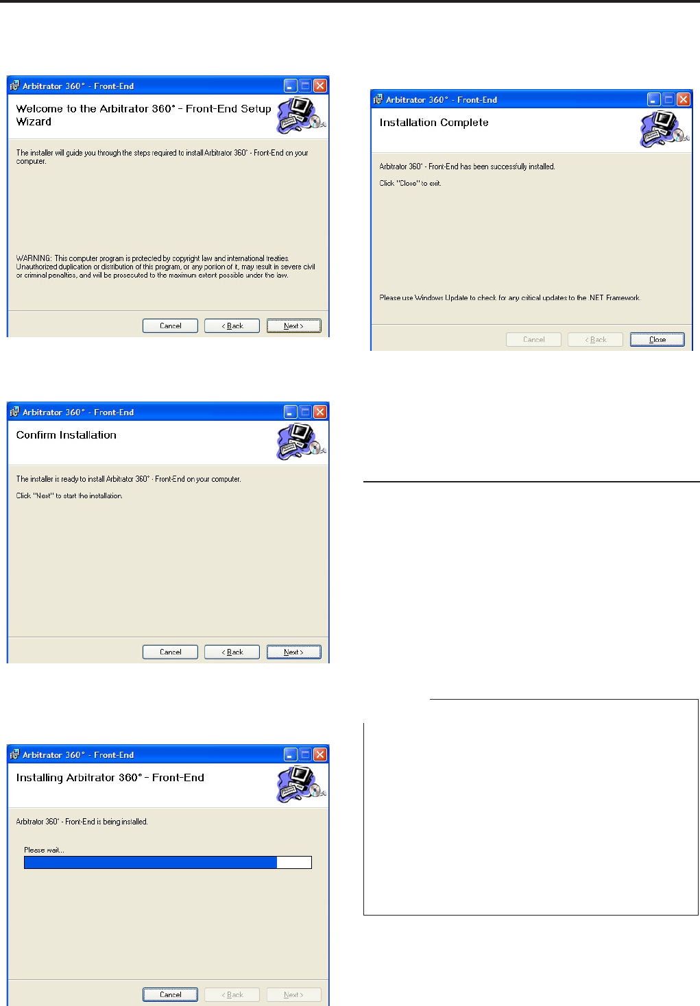
3. Click on [Next].
4. Click on [Next].
The conrmation screen appears.
5. Click on [Next].
The le will be transferred to the following folder:
/Program Files/Panasonic/ICV/FE
When the le transfer is completed, the screen
shown below appears.
6. Click on [Close].
Installation is completed, and the shortcut icon for
the Front-End application will be placed on the
desktop.
Remote updating
The Front-End application can be remotely updated
when the following conditions are satised:
A PC with the Front-End application installed is
connected to the Back-End Server.
The latest version of the Front-End application is
registered with the Back-End server.
Remote updating is set on the Back-End
Administrator application.
When the Front-End application receives an update
module from the Back-End Server, it is automatically
updated upon being restarted.
Notes
If the Interactive services dialog detection dialog box is
displayed, select "Show me the message."
If a dialog box prompting you to select Try Again,
Continue, or Exit Installation is displayed, select
Continue.
If a message "You must restart your system for the
conguration changes made to Arbitrator 360˚ – Back-
End Client to take effect. Click Yes to restart now or No
if you plan to manually restart later." is displayed, click
on [Yes]. Your PC will restart. If the PC does not restart,
recording on a DVD cannot be executed correctly.
•
•
•
•
•
•

Installing/Uninstalling (continued)
Uninstalling
Uninstall the Front-End application following the
procedures below.
Procedures for Windows XP
1. Click on the [Start] button.
2. Select Control Panel
3. Double-click on Add or Remove Programs.
The Currently installed programs window opens.
4. Select the program to be uninstalled.
5. Click on the [Remove] button.
A conrmation message appears.
6. Click on the [Yes] button.
Uninstalling of the selected program starts.
Procedures for Windows Vista
1. Click on the [Start] button.
2. Select Control Panel
3. Double-click on Programs and Features.
The Uninstall or change a program window opens.
4. Select the program to be uninstalled.
5. Click on Uninstall.
The User Account Control window opens.
6. Click on the [Allow] button.
The Uninstall window opens.
7. Click on the [Uninstall] button.
Uninstalling of the selected program starts.
10
11
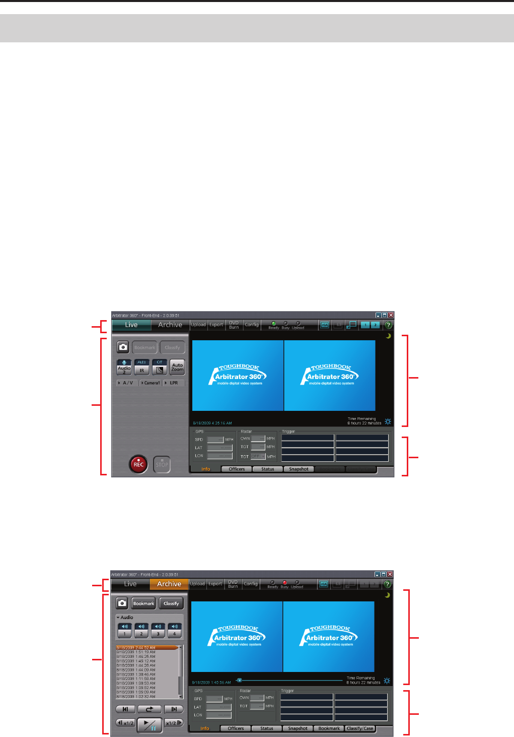
● Live mode
Toolbar
(See page 11.)
Video display
section
(See page 14.)
Property section
(See page 20.)
Live operation
section
(See page 15.)
● Archive mode
Toolbar
(See page 11.)
Video display
section
(See page 14.)
Property section
(See page 20.)
Playback
section
(See page 18.)
When you login the Front-End application, the Live-
mode screen will appear. On this screen, you can
monitor pictures captured by the cameras connected
to the Memory Card Video Recorder and record the
pictures. On the Archive-mode screen, you can play
back the recorded pictures.
Note on rst login
If the Live-mode screen does not appear upon rst
login of the Front-End application, check the following:
If the Windows Security Alert dialog box is
displayed
1. Select "Unblock."
2. Click on [OK].
If the Live-mode screen does not appear
Check the Firewall setting and change the setting as
described below.
Method 1:
1. Click on [Start].
2. Select [Control Panel].
3. Select "Windows Firewall."
4. For Windows Vista, select "Change Setting."
5. Check the Firewall setting.
If it is set to ON, check that the "Don’t allow exceptions"
check box is unchecked.
If checked, uncheck it.
Method 2:
1. Click on [Start].
2. Select [Control Panel].
3. Select "Windows Firewall."
4. Select the Exceptions tab.
5. Check the Front-End check box.
6. Click on [OK].
Description of the Screen Displays
Main Screen
10 11
Description of the Screen Displays (continued)
When the AG-CPD20P is connected
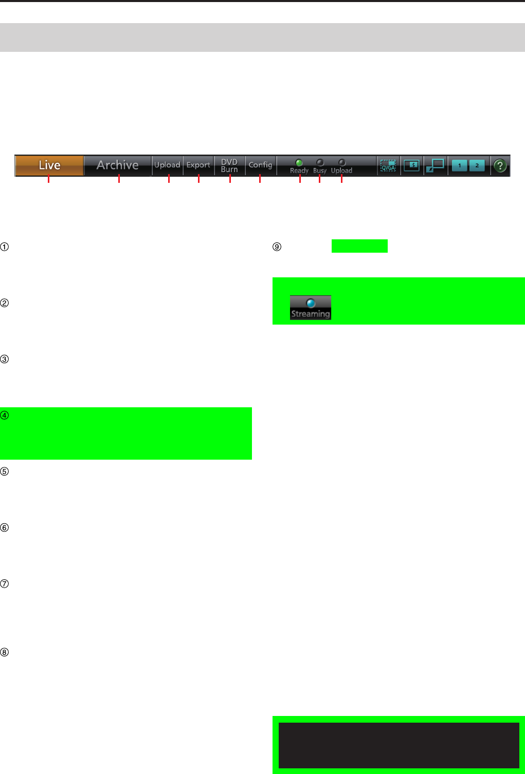
① ② ③ ④ ⑤ ⑥ ⑦ ⑧ ⑨
The buttons on the toolbar of the Main screen can
select the operation mode of the Front-End application
and switch the display mode of the screen. The lamps
indicate the status of the Memory Card Video Recorder.
Toolbar
Exporting from the Front-End Application and
Streaming are not available at present. Upgrading
is scheduled for the future.
Live button
For shifting to Live mode. The Main screen is
displayed.
(See "Viewing a Live Video," page 56.)
Archive button
For shifting to Archive mode. The Main screen is
displayed.
(See "Playback in Archive Mode," page 65.)
Upload button
For shifting to Upload mode.
(See "Upload Screen," page 24, and "Uploading
Files," page 74.)
Export button
For shifting to Export mode.
(See "Export Screen," page 25, and "Exporting
Files," page 75.)
DVD Burn button
For shifting to DVD Video Burn mode.
(See "DVD Burn Screen," page 26, and "Creating a
DVD," page 76.)
Cong button
For shifting to Conguration mode.
(See "Cong Screen," page 28, and "Administrator
Setup," page 79.)
Ready lamp
Lights when the SDHC Memory Cards loaded in the
SDHC Memory Card slots are recordable.
(See "Indicator Lamps and Recorder Status," page
112.)
Busy lamp
Lights or ashes while an SDHC Memory Card
is being accessed, such as during recording or
playback.
(See "Indicator Lamps and Recorder Status," page
112.)
Upload/Streaming lamp
The Upload lamp lights while data are being
uploaded or exported.
The Steaming lamp lights during streaming.
(See "Indicator Lamps and Recorder Status," page
112.)
1
Description of the Screen Displays (continued)
1
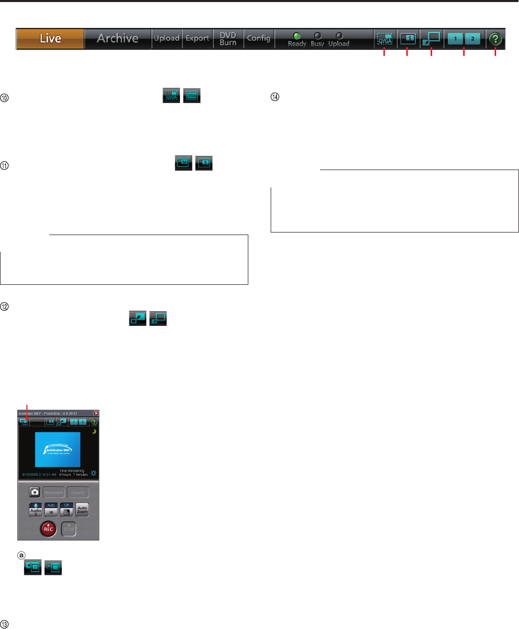
QVGA/VGA switch button ( )
Select to display the video at the size of either
QVGA or VGA.
(See "Switching the QVGA and VGA sizes," page
52.)
Main/Sub video switch button
(
)
During 1-screen mode, select to display either main
video or sub video.
(See "Switching the Main video and Sub video,"
page 53.)
Note
This button is enabled in simple operation mode or VGA
mode when main and sub videos are available.
Full/Simple Operation mode switch button
(only in Live mode) ( )
Switches the display mode between Full Operation
mode and Simple Operation mode.
(See "Switching Full/Simple Operation mode,"
page 51.)
● Simple Operation mode
ⓐ
Camera1 control panel display button
( )
The same operation buttons as those on the
Camera1 tab are displayed.
(See "Camera1 tab," page 16.)
Preset switch button
Select a display pattern from among Presets 1, 2,
and 3.
(See "Switching the Main video and Sub video,"
page 53, and "Preset Settings," page 81.)
Help button
When this button is clicked, the mouse pointer will
be turned to "→+?". Clicking on a button or input
eld with this pointer will display the description of
the clicked button/input eld.
Note
If you use Acrobat 9 or 8, the description may not be
displayed correctly when you click on a button or input
eld.
⑩ ⑪ ⑫ ⑬ ⑭
1
1
Description of the Screen Displays (continued)
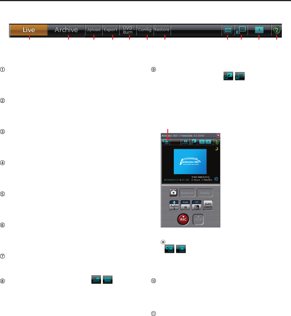
When the AG-CPD15P or AG-CPD10CRUP is connected
① ② ③ ④ ⑤ ⑥ ⑦ ⑧ ⑨ ⑩ ⑪
Live button
For shifting to Live mode. The Main screen is
displayed.
(See "Viewing a Live Video," page 56.)
Archive button
For shifting to Archive mode. The Main screen is
displayed.
(See "Playback in Archive Mode," page 65.)
Upload button
For shifting to Upload mode.
(See "Upload Screen," page 24, and "Uploading
Files," page 74.)
Export button
For shifting to Export mode.
(See "Export Screen," page 25, and "Exporting
Files," page 75.)
DVD Burn button
For shifting to DVD Video Burn mode.
(See "DVD Burn Screen," page 26, and "Creating a
DVD," page 76.)
Cong button
For shifting to Conguration mode.
(See "Cong Screen," page 28, and "Administrator
Setup," page 79.)
Restore button
For restoring a le.
(See "Restoring a File," page 78.)
QVGA/VGA switch button ( )
Select to display the video at the size of either
QVGA or VGA.
(See "Switching the QVGA and VGA sizes," page
52.)
Full/Simple Operation mode switch button
(only in Live mode) ( )
Switches the display mode between Full Operation
mode and Simple Operation mode.
(See "Switching Full/Simple Operation mode," page
51.)
● Simple Operation mode
ⓐ
Camera1 control panel display button
( )
The same operation buttons as those on the
Camera1 tab are displayed.
(See "Camera1 tab," page 16.)
Camera switching button
When the QVGA-size video display is selected,
select a camera to be displayed. Each click on this
button will toggle CAM1 and CAM2.
Help button
When this button is clicked, the mouse pointer will
be turned to "→+?". Clicking on a button or input
eld with this pointer will display the description of
the clicked button/input eld.
1
Description of the Screen Displays (continued)
1
Full operation mode
⑤
⑥
①
② ③ ④
Simple operation mode
⑤
⑥
② ④
①
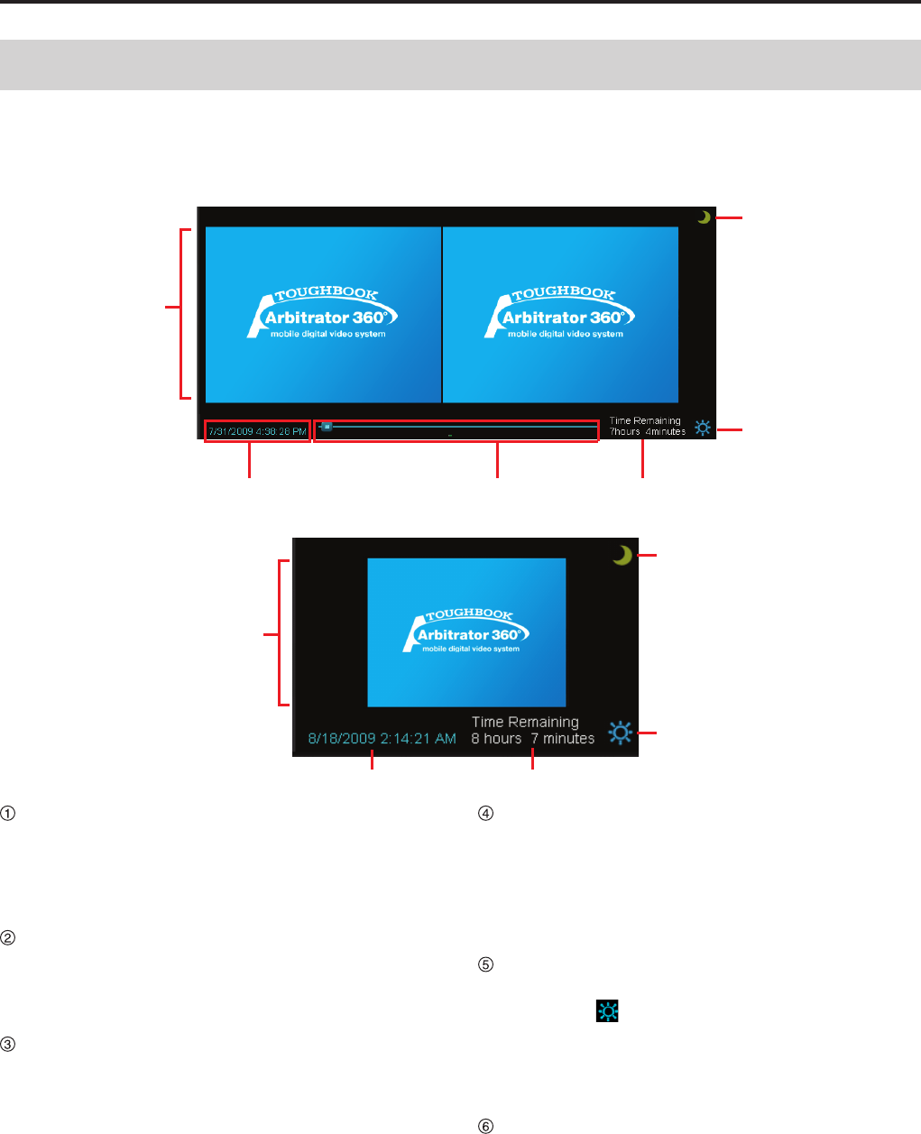
Video display section
When 1 VGA-size video is displayed, the video
is displayed at the center. When 2 videos are
displayed, the Main video is displayed on the left
and the Sub video is displayed on the right.
(See "Switching and Adjusting Display Mode," page 51.)
Date and time indication
During Live mode: The current date and time are
displayed.
During Archive mode: The date and time of the
current playback location is displayed.
Seek bar (only in Archive mode)
It is displayed only in Archive mode. The current
playback location is displayed.
Sliding the switch will change a playback location.
Clicking on the left side of the switch will move the
playback location backward by 1/20 of the content
length, and clicking on the right side will move the
playback location forward by 1/20 of the content
length.
The locations of the classify information and
bookmark are displayed on the bar.
Time Remaining indication
The remaining video recordable duration on the
SDHC Memory Cards loaded in the Memory
Card Video Recorder is displayed. If the current
recordable duration becomes shorter than the
preset value, the indication turns red, and a beep
sounds every 30 seconds.
Brightness adjustment button/indication
The brightness of the video display is adjusted.
When the [ ] button is clicked, the current
brightness level is displayed. Clicking on the [▲]
button makes the video display brighter, and
clicking on the [▼] button makes it darker.
(See "Adjusting image brightness," page 55.)
Day/Night switch button
The screen image is switched between Day mode
and Night mode. The entire screen will become
darker in Night mode.
(See "Switching Day and Night modes," page 54,
and "Day/Night View," page 86.)
In this section, you can monitor pictures captured by
the cameras connected to the Memory Card Video
Recorder and play back the recorded pictures.
Video Display Section
1
1
Description of the Screen Displays (continued)
Live Operation Section
In this section, you can control the pictures in the live
mode.
① ②
③
④
⑤
⑥
⑦⑧
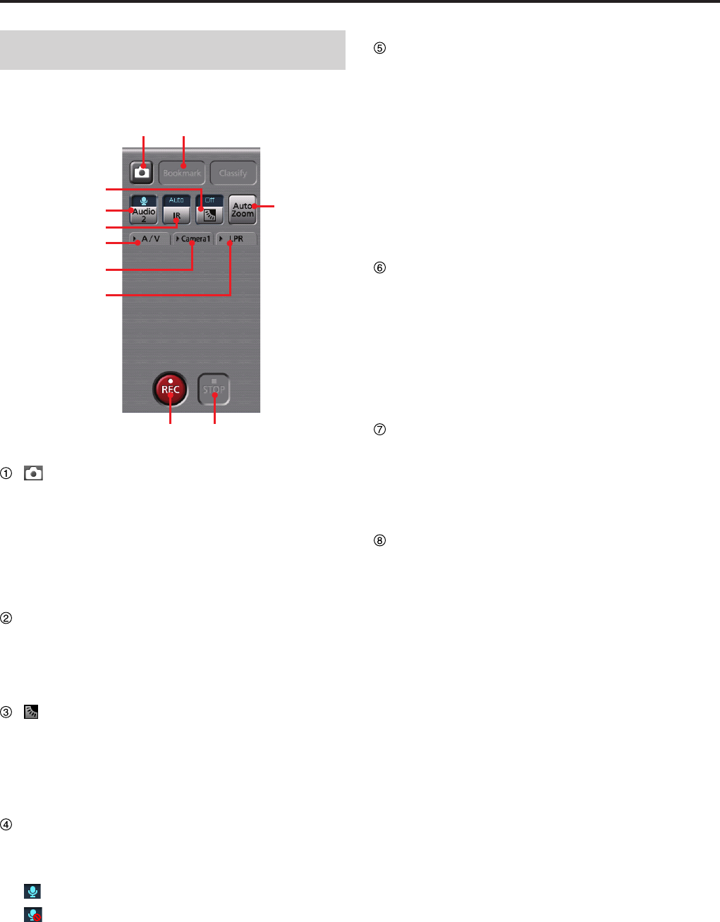
A/V tab
Camera1 tab
LPR tab
Snapshot button
A snapshot picture of a current-time live video will
be stored as a .BMP le.
Meta information will also be recorded with the
snapshot picture if this button is clicked during
recording.
(See "Creating a snapshot picture in record mode,"
page 64.)
Bookmark button
Click on this button during recording to create a
current-time bookmark.
(See "Adding bookmarks in record mode," page
63.)
Backlight compensation button/
indication
Turns the backlight compensation On or Off. The
current setting is indicated on the button.
(See "Making a backlit image easier to view," page
56.)
Audio 2 button/indication
Select whether the audio channel 2 input signal
is to be recorded or not. The current setting is
indicated on the button.
: The selected audio channel signal is recorded.
: The audio channel 2 signal is not recorded.
(See "Turning audio recording On or Off," page 62.)
IR button/indication
Switches IR mode of the camera. Each time this
button is clicked, On, Off, and Auto is cyclically
selected. The current setting is indicated on the
button.
On: Sets IR mode to ON.
Off: Sets IR mode to Off.
Auto: Automatically changes IR mode depending
on ambient brightness.
(See "Making a dark image easier to view," page
57.)
Auto Zoom button
Controls the automatic zooming function of the
camera. Zoom-in, pause, and zoom-out operation
will be automatically performed. The zoom ratio and
pause time can be set.
If other camera operation is performed during an
auto zoom operation, auto zoom will be canceled.
(See "Zooming in live mode," page 56, and
"Camera1," page 83.)
REC button
Click to start recording live video and audio. "REC"
is indicated on the display during recording and a
red frame appears around the video. A signal tone
sounds every 30 seconds.
(See "Starting and stopping recording," page 59.)
STOP button
Click to stop recording live video and audio.
(See "Starting and stopping recording," page 59.)
When the setting of Force Classify on the Rec/
Play screen in Administrator Setup is FORCE or
ENABLE, the Classify Input screen is displayed.
(See "Setting the classify information," page 59,
and "Classify," page 104.)
1
Description of the Screen Displays (continued)
1
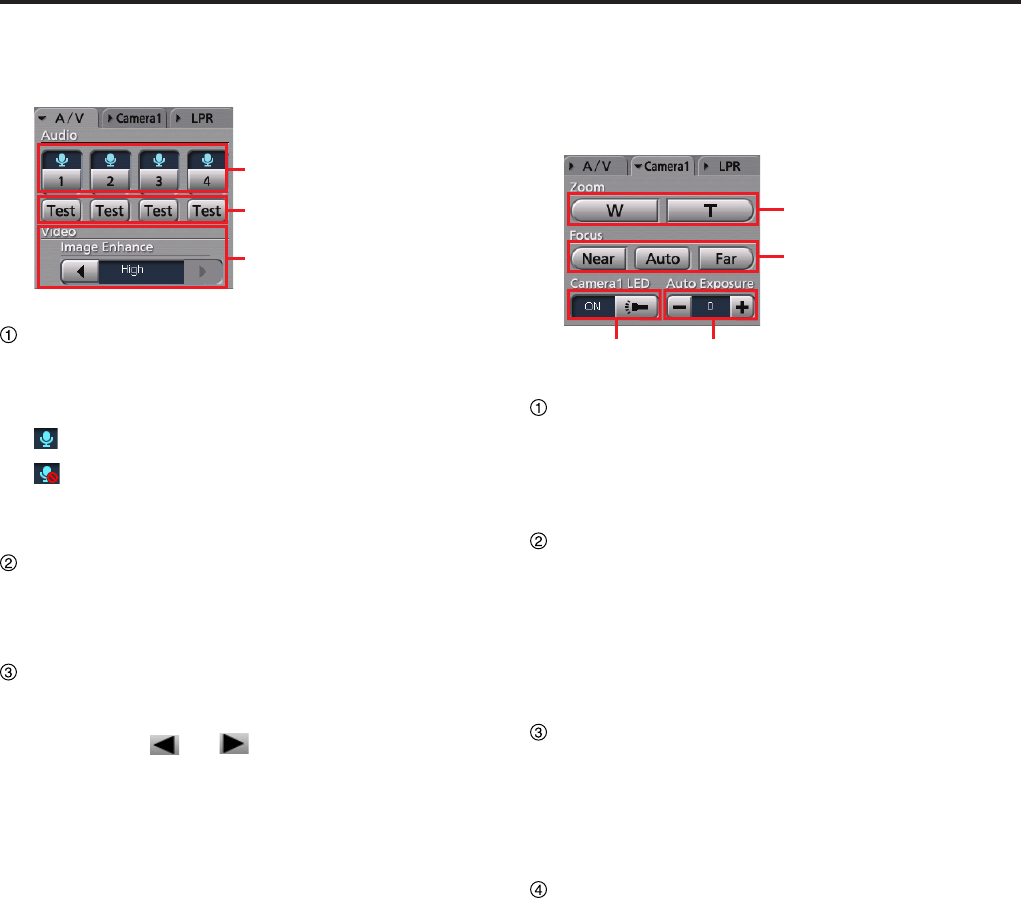
A/V tab
This is a panel for audio and video control.
①
②
③
Recording audio switch buttons/indications
Switch whether the selected audio channel is to be
recorded or not. The current setting is indicated on
the button.
: The selected audio channel signal is recorded.
: The selected audio channel signal is not
recorded.
(See "Turning audio recording On or Off," page 62.)
Test buttons
While a button is held pressed, the corresponding
audio channel signal will be output from the PC.
(See "Checking audio," page 57.)
Video Image Enhance button
For adjusting the brightness of a dark video image
on the Main screen.
Click on the [ ] or [ ] button to change the
setting. The current setting is indicated at the
center.
Off: No video image enhancing
Low: Low video image enhancing
High: High video image enhancing
(See "Compensating image brightness," page 58)
Camera1 tab
This is a panel for operating the color camera. The
Camera1 tab cannot be selected if no color camera is
connected to the Memory Card Video Recorder.
①
②
③ ④
Zoom buttons
For adjusting zooming.
W: For zooming out
T: For zooming in
(See "Zooming in record mode," page 60.)
Focus buttons
For adjusting focus.
Near: For focusing on a object nearby
Auto: For automatic focusing
Far: For focusing on a distant object
(See "Focusing," page 60.)
Camera1 LED button/indication
Turns the [REC] lamp of the color camera On or
Off. The current setting is indicated on the left of
the button.
(See "Turning Off the [REC] lamp of the color
camera during recording," page 61.)
Auto Exposure button/indication
For adjusting the exposure. The current setting
value is indicated at the center.
-: Each click on this button decreases the exposure
value by 1. The value can be decreased to -2.
+: Each click on this button increases the exposure
value by 1. The value can be increased up to 2.
(See "Adjusting image brightness in record mode,"
page 61.)
1
1
Description of the Screen Displays (continued)
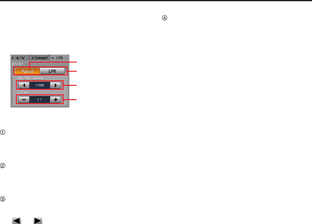
LPR tab
The LPR tab is displayed when Init LPR Mode is set
to ENABLE on the Camera1 screen in Administrator
Setup.
(See "Init LPR Mode," page 85.)
①
②
③
④
(See "LPR setting," page 62.)
Patrol button
For setting the Memory Card Video Recorder to
Patrol mode. The values for Shutter Speed and
Zoom are set for Patrol mode.
LPR button
For setting the Memory Card Video Recorder to
LPR mode. The values for Shutter Speed and
Zoom are set for LPR mode.
Shutter Speed buttons/indication
Set the shutter speed. The current setting value is
indicated at the center.
[ ] or [ ] button increases/decreases the
shutter speed. Each click on one of these buttons
changes the setting value, as shown below:
In Patrol mode: Auto, 1/100, 1/500, 1/1000
In LPR mode: Auto, 1/500, 1/1000
(See "Setting the shutter speed," page 62.)
Zoom buttons/indications
Set the zoom. The current setting value is indicated
at the center.
Clicking on the [-] or [+] button increases/decreases
the zoom value. The adjustable range is from 1.0 to
22.0. The magnitude of changes varies depending
on the zoom magnication, as shown below:
The zoom range x1.0 to x3.0: increase and
decrease by x0.1
The zoom range x3.0 to x5.0: increase and
decrease by x0.2
The zoom range x5.0 to x10.0: increase and
decrease by x0.5
The zoom range x10.0 to x22.0: increase and
decrease by x1.0
(See "Setting the zoom" page 63.)
1
Description of the Screen Displays (continued)
1
Playback Section
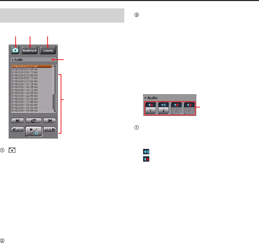
① ② ③
Audio tab
Playback section
(Snapshot) button
A snapshot picture will be created and stored as
a BMP le in the folder that is set in Administrator
Setup.
If this button is clicked during playback, the
playback pauses and a snapshot picture is created.
The playback location for a snapshot picture is
recorded as meta information. The Snapshot tab
is displayed in the Property section. This button
is disabled during Fast Forward or Fast Rewind
mode.
(See "Snapshot tab," page 22, and "Creating a
snapshot picture in archive mode," page 70.)
Bookmark button
For creating a new bookmark.
If this button is clicked during playback, the
playback pauses and a bookmark is created The
Bookmark tab is displayed in the Property section.
This button is disabled during Fast Forward or Fast
Rewind mode.
(See "Adding bookmarks in archive mode,"
page 69.)
Classify button
For creating a new classify information item.
If this button is clicked during playback, the
playback pauses and a classify information item
is created. The Classify tab is displayed in the
Property section. This button is disabled during Fast
Forward or Fast Rewind mode, or if any classify tag
is registered.
(See "Classify/case tab," page 23, and "Creating
classify information," page 69.)
Audio tab
This is a panel for audio control.
①
Audio mute buttons/indications
Select whether the playback sound of the selected
audio channel is On or OFF. The current setting is
indicated on the button.
: Audio mute Off (Playback sound On)
: Audio mute On (Playback sound Off)
If no sound is recorded on a channel, the button
corresponding to the channel is disabled.
Mute status is memorized in the Front-End
Application, and will be restored when the Front-
End Application restarts.
(See "Turning playback sound On or Off," page 68.)
1
1
Description of the Screen Displays (continued)
Playback Section
This panel controls playback of video signals recorded
on the SDHC Memory Cards.
(See "Playback," page 65.)
①
②
③
④
⑤
⑥
⑦
File list
For displaying a list of video les recorded on
the SDHC Memory Cards that are loaded in the
Memory Card Video Recorder.
Double-clicking on a lename will start playback of
the le from the beginning.
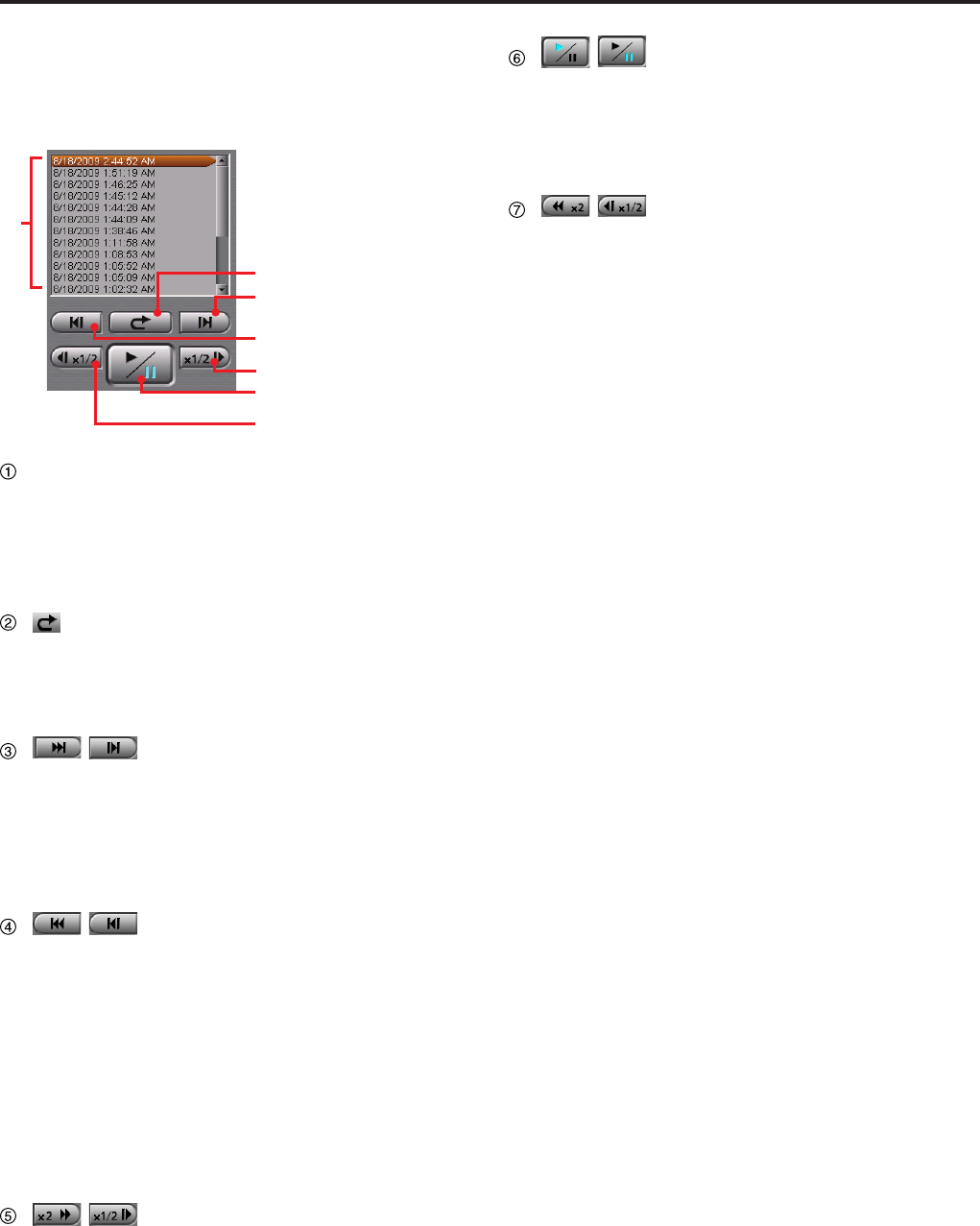
(Quick replay) button
Playback from a location 7 seconds before the
button is clicked starts. If this button is clicked
within 7 seconds from the beginning of a le,
playback starts from the beginning of the le.
/
(Skip forward/Frame forward)
button
If you click on this button during playback, fast
forward, or fast rewind mode, playback from the
beginning of the next le on the le list will start.
If this button is clicked during pause, an image one
frame after the current frame will be displayed.
/
(Skip back/Frame rewind) button
If this button is clicked within 5 seconds from the
beginning of a le, playback will start from the
beginning of the previous le on the le list. If this
button is clicked after 5 seconds from the beginning
of a le, playback will start from the beginning of
that le.
If this button is clicked during fast forward or fast
rewind mode, playback from the beginning of the
previous le on the le list will start.
If this button is clicked during pause, an image one
frame before the current frame will be displayed.
/
(Fast forward/Slow playback)
button
If this button is clicked during playback, fast forward
playback will start.
If this button is clicked during pause, slow playback
will start.
Each time this button is clicked, fast forward or slow
playback speed changes.
At the end of the le, playback pauses.
/
(Playback/Pause) button/
indication
Each click on this button will toggle playback and
pause modes. The current status is indicated on
the button.
At the end of the le, playback pauses.
/
(Fast rewind/Slow reverse
playback) button
If this button is clicked during playback, fast rewind
playback will start.
If this button is clicked during pause, slow reverse
playback will start.
Each time this button is clicked, fast rewind or slow
reverse playback speed changes.
At the beginning of the le, playback pauses.
0
Description of the Screen Displays (continued)
1
Property Section
You can check the information for the pictures in the
live mode, or for the recorded pictures. Click on a tab,
and the corresponding page will be displayed.
Info tab
Officers tab
Status tab
Snapshot tab
Bookmark tab
Classify/Case tab
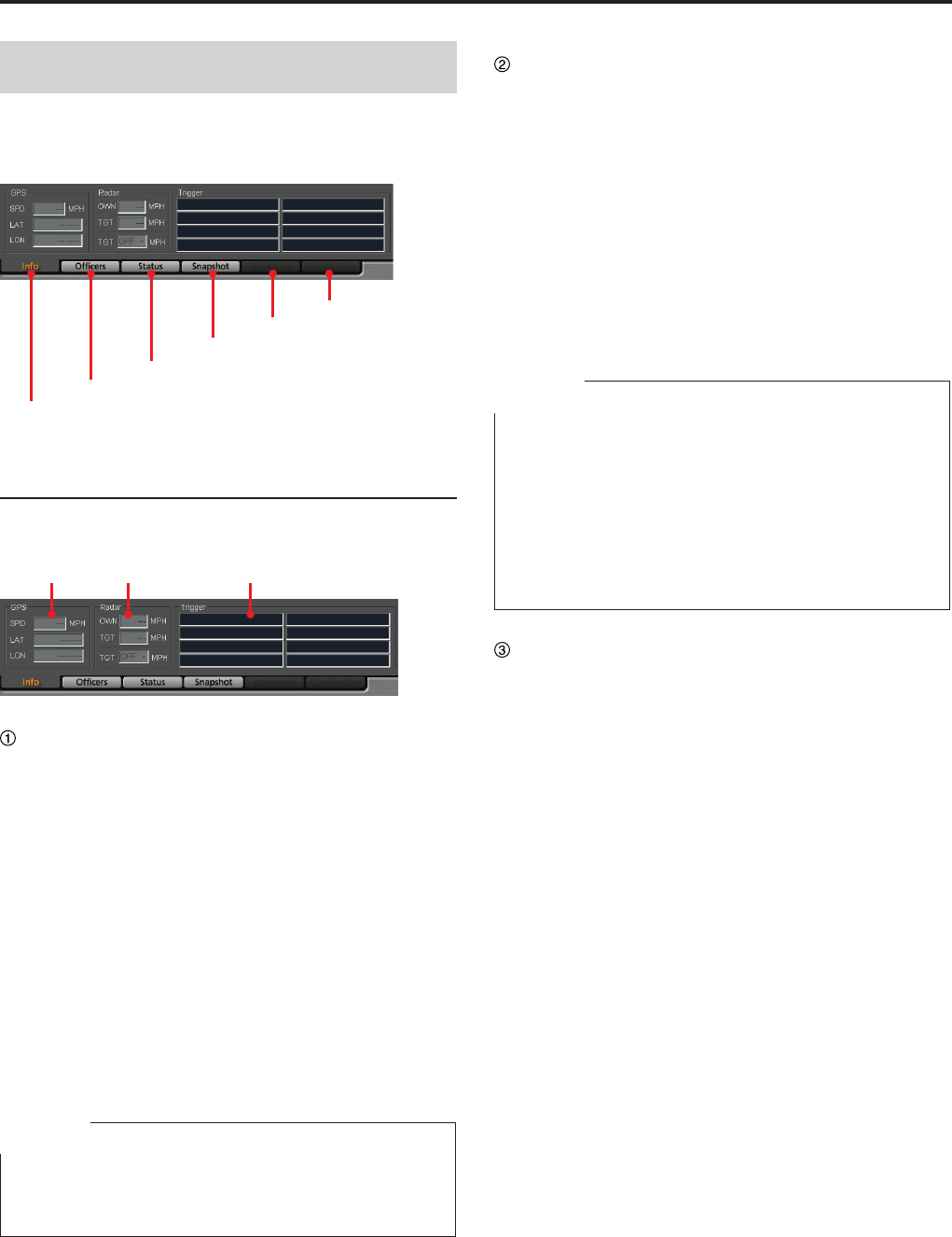
Info tab
Meta information is displayed.
(See "Meta information," page 71.)
① ② ③
GPS information
The following information obtained from the GPS
will be displayed.
In Live mode, the displayed data are updated at
intervals that are set on the Radar/GPS screen in
Administrator Setup.
In Archive mode, the displayed data are updated
according to data sent from the Memory Card Video
Recorder.
SPD: Vehicle speed
LAT: Latitude. 00.000000N denotes north latitude,
and 00.000000S denotes south latitude.
LON: Longitude. 000.000000W denotes west
longitude, and 000.000000E denotes east
longitude.
Note
If the AG-CPD15P Memory Card Video Recorder is used,
the GPS information in Live mode may not be displayed
until the vehicle moves.
Radar information
The following information obtained from the radar
gun will be displayed.
In Archive mode, the displayed data are updated,
according to data sent from the Memory Card Video
Recorder.
OWN: Speed of your vehicle
TGT: Speed of the target vehicle
TGT (setting): Speed of a target vehicle that has
been set in the Memory Card Video Recorder.
If the TGT value exceeds this setting value, a
trigger event will be generated.
Notes
TGT (setting) is displayed only when Trigger 15
or Trigger 16 is set to TGT(REC), TGT(P1REC),
TGT(P2REC), or TGT(P3REC) are set to TGT on the
Triggers screen in Administrator Setup.
(See "Triggers," page 110.)
TGT (setting) is not displayed if Connection of Radar is
set to OFF on the Radar/GPS screen.
(See "GPS," page 99.)
•
•
Trigger information
The GPI input status is displayed when Trigger is
set to ON and the trigger name is specied on the
Trigger screen in Administrator Setup.
If the number of connected GPI is up to 8, the
status is displayed in 4 lines and 2 rows. If the
number of connected GPI is more than 8, the status
is displayed in 4 lines and 4 rows. The GPI channel
number and trigger name are displayed like "GPI
channel number : trigger name" in each cell.
0
1
Description of the Screen Displays (continued)
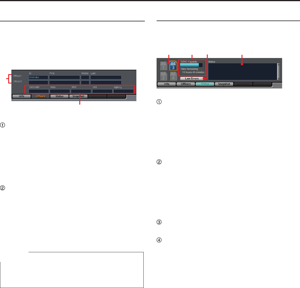
Ofcers tab
Ofcer information is displayed.
In Live mode, the setting data of the Memory Card
Video Recorder are displayed.
In Archive mode, the meta le data embedded in the
currently selected video signal are displayed.
(See "Ofcer information," page 71.)
②
①
Ofcer1, Ofcer2 information
Data for Ofcers 1 and 2 are displayed.
ID: Ofcer ID
First: First name
Middle: Middle name
Last: Last name
Shift information
Vehicle ID: Vehicle ID
Area: Area
Shift: Shiftwork pattern
Unit: Unit
Agency: Police agency
Note
The name of each eld is the default setting for Field1 to
Field5. The eld name can be changed upon installation
of the Back-End server.
Status tab
The status of the SDHC Memory Cards loaded in the
Memory Card Video Recorder is displayed.
(See "Status information," page 72.)
① ③② ④
SDHC indication
The status of the SDHC Memory Cards loaded in
the Memory Card Video Recorder is displayed.
In Live mode, the status of the memory card to be
used for recording is displayed.
In Archive mode, the status of the memory card in
which the video signal being played back is stored
is displayed.
SDHC Capacity indication
The remaining duration of the SDHC Memory
Cards loaded in the Memory Card Video Recorder
is displayed with a bar indication. The remaining
recordable time with the current setting will be
displayed in Time Remaining.
Just after an SDHC memory card is inserted, the
bar indicates full capacity for about 1 minute.
Last Errors button
For displaying the most recent error data.
Status indication
In Live mode, an error code and a message for
registering Snapshot, Bookmark, and Classify are
displayed.
In Archive mode, the recording date and time of
the video le selected in the le list, the playback
duration, and a message for registering Snapshot,
Bookmark, and Classify are displayed.
Description of the Screen Displays (continued)
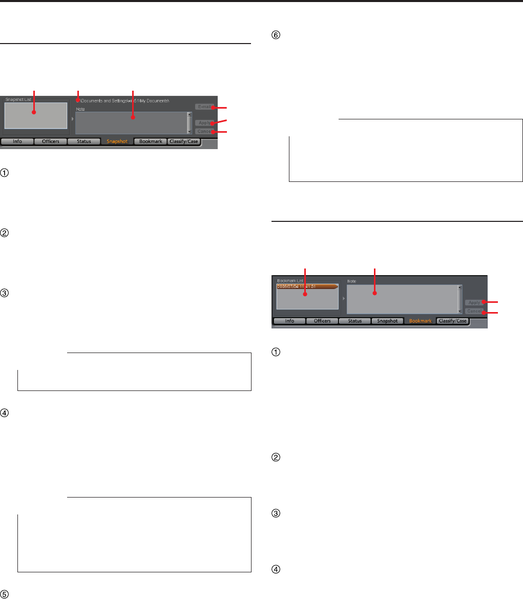
Snapshot tab
The snapshots and their notes are displayed.
(See "Snapshot information," page 72.)
① ③②
④
⑤
⑥
Snapshot List
A list of snapshots in the selected video le is
displayed. If a snapshot is selected, playback
pauses at the location of the snapshot.
Snapshot folder path
The directory of snapshot data storage location
that has been set on the File Transfer screen in
Administrator Setup is displayed.
Note
The note for the snapshot selected in the Snapshot
List is displayed. The note can be edited if playback
is paused at the snapshot location.
Note
The note of a snapshot cannot be edited in Live mode.
E-mail button
For attaching the snapshot selected in the
Snapshot List to e-mail.
This button is disabled if no snapshot is selected.
The latest snapshot will be attached to e-mail
during Live mode.
Note
This button functions correctly only when the
internet e-mail program for Windows is registered.
For registering the internet e-mail program, refer to
Windows Help.
Apply button
For updating snapshot data when the note of a
snapshot is edited. This button is disabled when no
note is edited.
Cancel button
If you click on this button before clicking on the
Apply button while editing a note, that editing
is canceled, and the note before editing will be
displayed. This button is disabled while no note is
being edited.
Note
When the AG-CPD15P is used, Snapshot List and
Note are displayed in gray and cannot be operated.
Only the E-mail button is enabled.
Bookmark tab (only in Archive mode)
The bookmarks and their notes are displayed.
(See "Bookmark information," page 73.)
① ②
③
④
Bookmark List
A list of bookmarks in the selected video le is
displayed. If a bookmark is selected, the bookmark
position is located and the unit enters playback
pause mode.
When the playback position reaches a bookmark
position during playback, the bookmark will be
selected.
Note
The note for the bookmark selected in the
Bookmark List is displayed. The note can be edited
if playback is paused at the bookmark location.
Apply button
For updating bookmark data when the note of a
bookmark is edited. This button is disabled when
no note is edited.
Cancel button
If you click on this button before clicking on the
Apply button while editing a note, that editing
is canceled, and the note before editing will be
displayed. This button is disabled while no note is
being edited.
Description of the Screen Displays (continued)
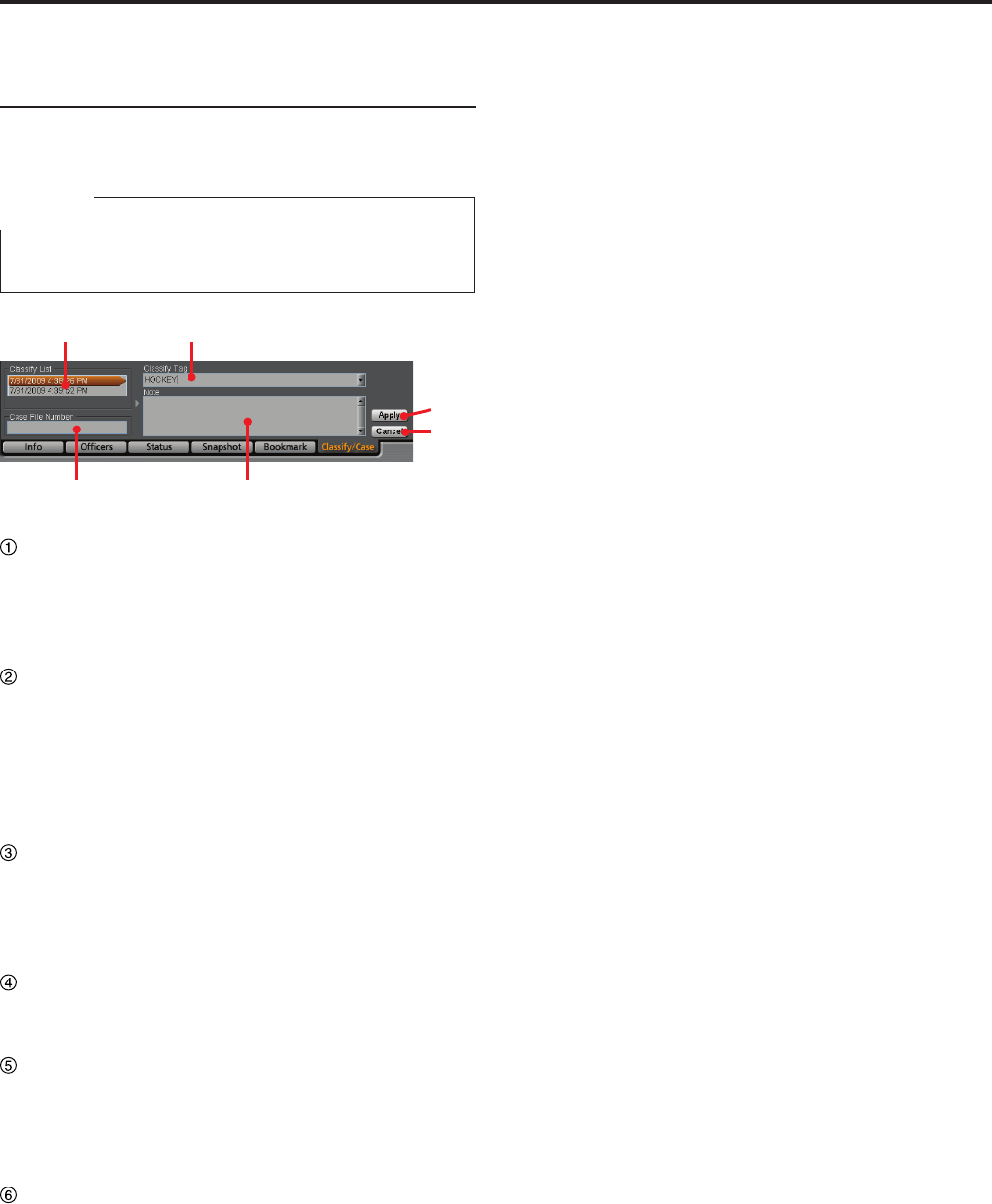
Classify/Case tab (only in Archive
mode)
The classify information is displayed.
(See "Classify information," page 73.)
Note
If the AG-CPD15P Memory Card Video Recorder is used,
the Event type of the AG-CPD15P is displayed as Classify.
①
④ ③
②
⑤
⑥
Classify List
A list of classify information in the selected video
le is displayed. If a classify information item is
selected, that position is located and the unit enters
playback pause mode.
Classify Tag
The classify tag selected in the Classify List is
displayed.
A classify tag can be edited if playback is paused at
the classify information position. Select a tag from
the classify tags registered on the Rec/Play screen
in Administrator Setup.
Note
The classify information note selected in the
Classify List is displayed.
A classify information note can be edited if playback
is paused at the classify information position.
Case File Number
Enter a case le number. The input case le
number will be recorded in the bookmark le.
Apply button
For updating a classify information item when its
classify tag, note or Case File Number are edited.
This button is disabled when neither Classify Tag
nor Case File Number, nor note is edited.
Cancel button
If you click on this button before clicking on the
Apply button while editing a classify tag, note, or
the Case File Number, that editing is canceled
and the status before editing will be restored. This
button is disabled if no classify tag or note, or Case
File Number has been edited.
Description of the Screen Displays (continued)
③
⑤
⑥
④
①②
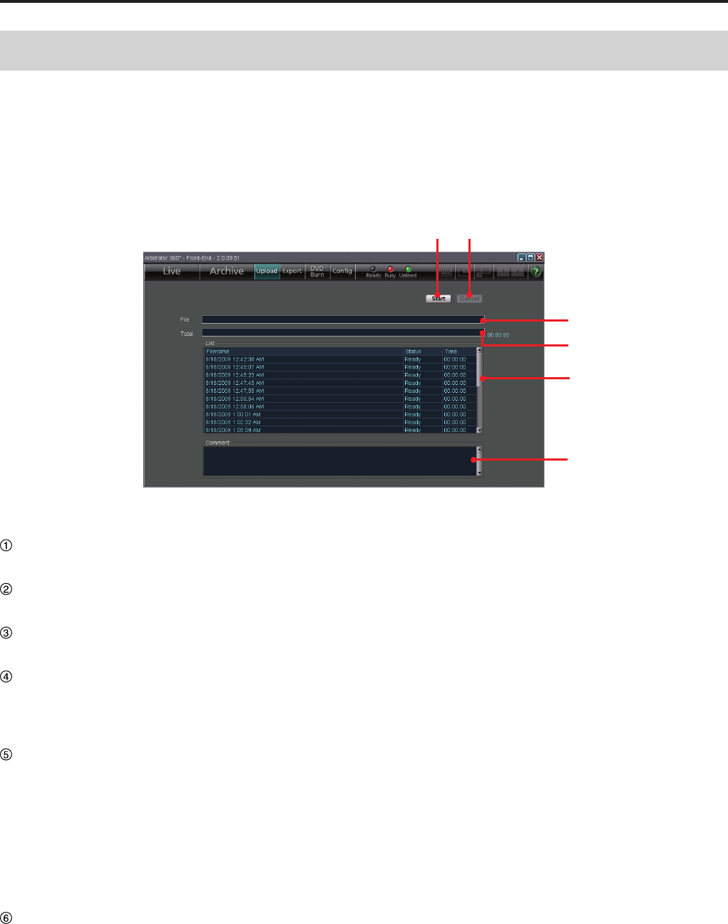
Start button
For starting uploading.
Cancel button
For canceling uploading.
File bar
Indicates the progress of current le uploading.
Total bar
Indicates the progress of all les to be uploaded.
An estimate time required for completion of
uploading is displayed at the right of the bar.
List
A list of les to be uploaded is displayed.
FileName: Filenames of les to be uploaded
Status: Statuses of les (Ready, Transferring,
Done, Error, Abort)
Time: For a le being uploaded, the time passed
from the beginning of uploading is displayed.
(For a le already uploaded, the time required for
uploading is displayed.)
Comment
While connecting or uploading, the current status is
displayed.
If an error is generated during uploading, the
lename for which the error was generated and the
error content are displayed.
When the [Upload] button of the Toolbar is clicked, the
Upload screen appears.
Video data recorded in the Memory Card Video
Recorder can be uploaded to the Back-End server.
(See "Uploading Files," page 74.)
Upload Screen
Description of the Screen Displays (continued)
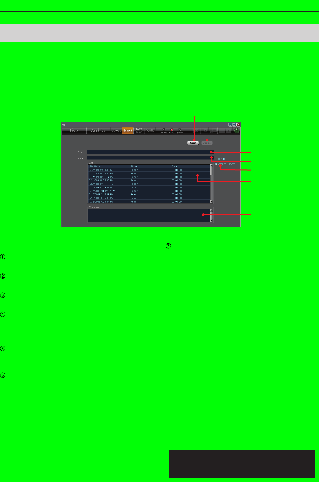
③
④
⑤
⑥
⑦
①②
Start button
For starting exporting.
Cancel button
For canceling exporting.
File bar
Indicates the progress of current le exporting.
Total bar
Indicates the progress of all les to be exported. An
estimate time required for completion of export is
displayed at the right of the bar.
With AV Viewer
Place a check mark when exporting the dedicated
player application together.
List
A list of les to be exported is displayed.
FileName: Filenames of les to be exported
Status: Statuses of les (Ready, Transferring,
Done, Error)
Time: For a le being exported, the time passed
from the beginning of exporting is displayed. For a
le already exported, the time required for exporting
is displayed.
Comment
If an error is generated during export, the lename
for which the error was generated and the error
content are displayed.
When the [Export] button of the Toolbar is clicked, the
Export screen appears.
Video data recorded in the Memory Card Video
Recorder can be exported to the hard disk of a PC or
removable media.
(See "Exporting Files," page 75.)
Export Screen
Exporting from the Front-End Application is not
available at present. Upgrading is scheduled for
the future.
Description of the Screen Displays (continued)
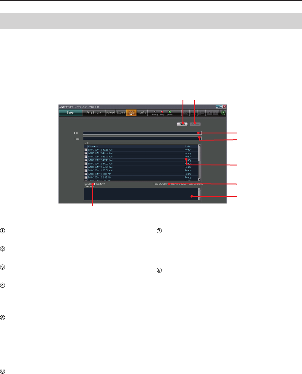
③
④
①②
⑤
⑥
⑦
⑧
Start button
For starting outputting data for burning a DVD.
Cancel button
For canceling output.
File bar
Indicates the progress of current le output.
Total bar
Indicates the progress of all les to be output. An
estimate time required for completion of output is
displayed at the right of the bar.
List
A list of les to be output is displayed. The les with
a check mark in the check box will be output.
File Name: Filenames of les to be output
Status: Statuses of les (Ready, Transferring,
Done, Error, Abort, Transferred, Burning,
Converting, Verifying)
Total Duration
Total playback period of a selected le is displayed
for Main video and Sub video separately.
Comment
The current status is displayed.
If an error is generated during output, the lename
for which the error was generated and the error
content are displayed.
Selected Files
Total number of les checked on the List is
displayed. A maximum of 49 les can be selected.
When the [DVD Burn] button of the Toolbar is clicked,
the DVD Burn screen appears.
Video data recorded in the Memory Card Video
Recorder can be output in DVD-Video format for
recording onto a DVD.
(See "Creating a DVD," page 76.)
DVD Burn Screen
Description of the Screen Displays (continued)
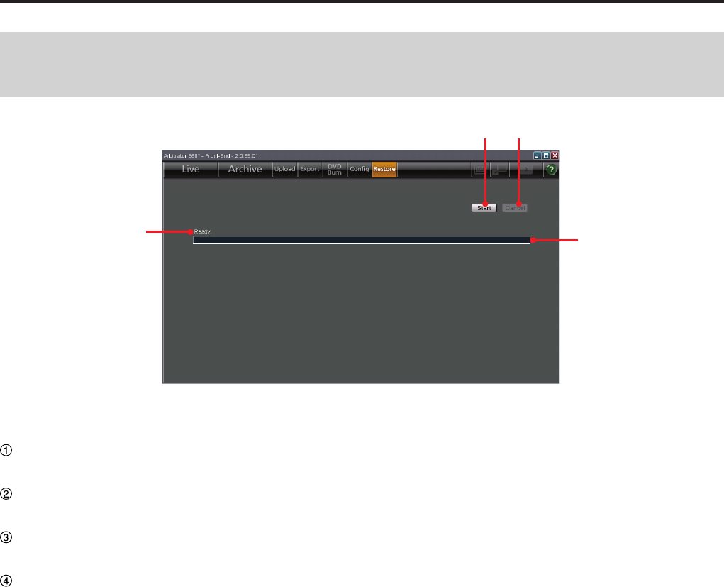
Restore Screen (Provided Only with the AG-CPD15P and AG-
CPD10CRUP)
①②
③
④
Start button
For starting restoring.
Cancel button
For canceling restoring.
Progress bar
Indicates the progress of current le restoring.
Status indication
Indicates the current status of restoring.
(Ready Restoring)
Completed Restoring
Aborted Restoring the le
•
•
•
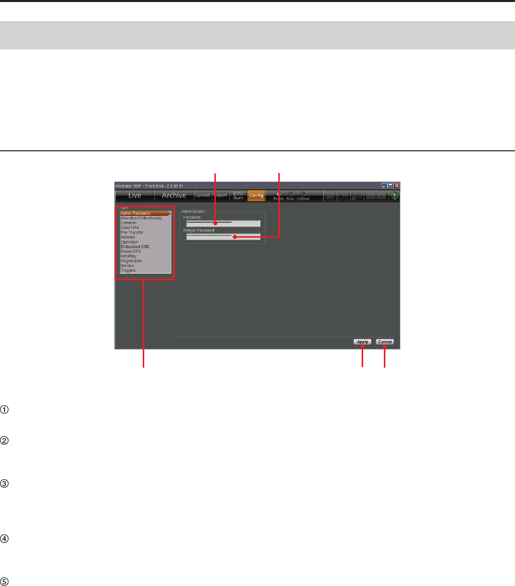
Description of the Screen Displays (continued)
①②
③④⑤
Password
For inputting an administrator password.
Retype Password
Re-enter the same string of password input in the
Password eld for reconrmation.
Item list
A list of the setting screens is displayed. Clicking
on a screen name will display the corresponding
setting screen.
Apply button
For changing the settings of the Memory Card
Video Recorder to those set in the Cong screen.
Cancel button
For canceling changes.
When the [Cong] button of the Toolbar is clicked,
the Cong screen appears. An administrator can
make settings for the conguration of the Front-End
application.
(See "Administrator Setup," page 79.)
On default settings
The default settings for various items are shown on the
Setup list on pages 113 to 127.
Cong Screen
Admin Password screen
Description of the Screen Displays (continued)
Allocation (Video/Audio) screen
⑤
① ③ ④
②
(See "Allocation (Video/Audio)," page 80.)
Resolution/RecordRate
ⓐ
ⓑ
Main
The resolution and bit rate of the main video can be
set.
Setting values: D1 HI (720x480, high quality
mode), D1 STD (720x480, standard quality
mode), D1 10 (720x480, 10 frames/second), CIF
(352x240, low quality mode)
Sub
The resolution and bit rate of the sub video can be
set.
Setting values: D1 HI (720x480, high quality
mode), D1 STD (720x480, standard quality
mode), D1 10 (720x480, 10 frames/second), CIF
(352x240, low quality mode)
Notes
If either of the Main or Sub Resolution/RecordRec is set
to "D1 10", the other is also set to "D1 10".
If you change the displayed conguration setting screen
without clicking on [Apply] after changing settings, "Save
and Apply Changes?" appears. Click on [Yes] then
change the screen.
•
•
Connection Camera
ⓐ
ⓑ
Camera1, Camera2, Camera3, Camera4,
Camera5, Camera6
Set if a camera is connected to each of
[CAMERA 1], [2], [3], [4], [5], and [6] connectors on
the Memory Card Video Recorder. If the camera is
connected, set to ON, and if it is not connected, set
to OFF.
Detect button
Click to automatically detect cameras connected to
the Memory Card Video Recorder.
0
Description of the Screen Displays (continued)
1
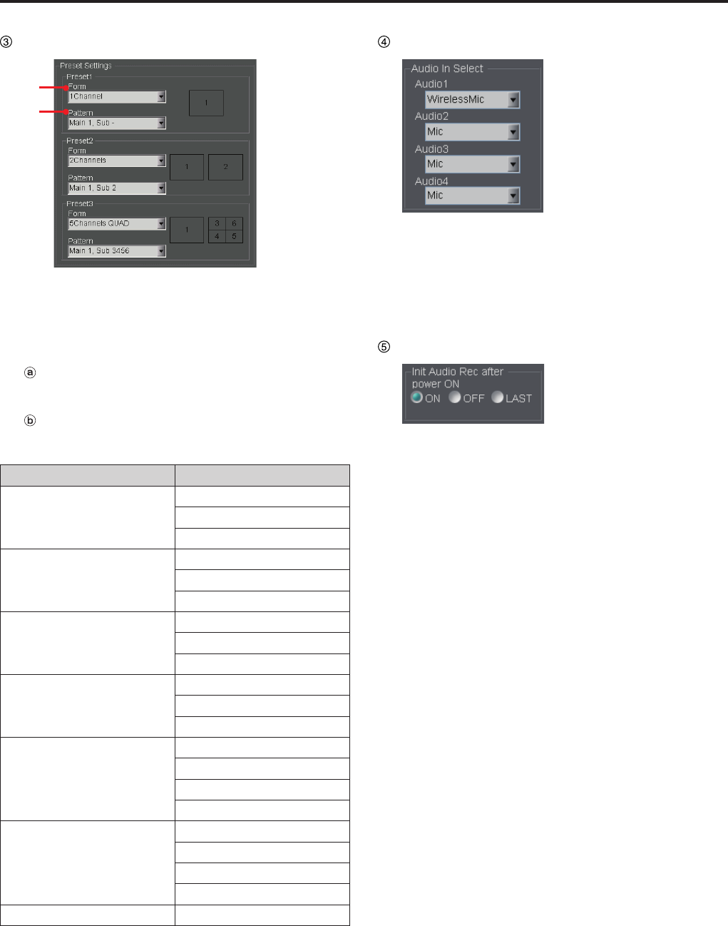
Preset Settings
ⓑ
ⓐ
For setting the channel mode and camera
connection pattern for Preset 1, Preset 2, and
Preset 3.
(See "Preset Settings," page 81.)
Form
Set the channel mode.
Pattern
Set the camera connection pattern.
Setting values for Form and Pattern:
Form Pattern
1Channel Main 1, Sub -
Main 2, Sub -
Main 3, Sub -
2Channels Main 1, Sub 2
Main 1, Sub 3
Main 2, Sub 3
4Channels QUAD Main -, Sub 1456
Main -, Sub 2456
Main -, Sub 3456
4Channels PANORAMA Main -, Sub 1456
Main -, Sub 2456
Main -, Sub 3456
5Channels QUAD Main 1, Sub 2456
Main 1, Sub 3456
Main 2, Sub 3456
Main 3, Sub 2456*1
5Channels PANORAMA Main 1, Sub 2456
Main 1, Sub 3456
Main 2, Sub 3456
Main 3, Sub 2456*1
None*2
*1 This setting is enabled when the camera connected
to the [CAMERA 1] connector is set to OFF.
*2 "None" is not selected for Preset1 unless all camera
connections are set to OFF.
Audio In Select
Select the type of microphones connected to
each of [AUDIO IN 1], [2], [3], and [4] connectors
on the Memory Card Video Recorder or turn the
microphone off.
Setting values: Mic, Wireless Mic, Off
Init Audio Rec after power ON
Set the audio recording status upon startup of the
Memory Card Video Recorder. The setting will be
applied to all four audio channels.
Setting values: ON, OFF, LAST
0
1
Description of the Screen Displays (continued)
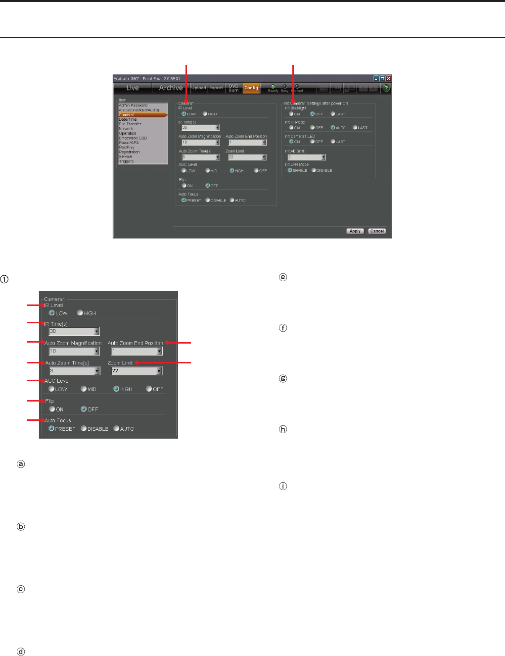
Camera1 screen
① ②
(See "Camera1," page 83.)
Camera1
ⓔ
ⓐ
ⓑ
ⓒ
ⓓ
ⓖ
ⓗ
ⓘ
ⓕ
IR Level
Set the IR level after automatic switching of the IR
function.
Setting values: LOW, HIGH
IR Time[s]
Set the detection time for automatic switching of
the IR function.
Setting values: 10, 30, 60, 300 seconds
Auto Zoom Magnication
Set the maximum zoom magnication during
automatic zooming.
Setting values: 1, 2, 3, 4, 5, 7, 10, 15, 22
Auto Zoom Time[s]
Set the keeping time of the maximum zoom
magnication during automatic zooming.
Setting values: 3, 5, 8 seconds
Auto Zoom End Position
Set the automatic zooming end magnication.
Setting values: 1, 2, 3, 4, 5, 7, 10, 15, 22, LAST
Zoom Limit
Set the maximum zoom magnication.
Setting values: 22, 220
AGC Level
Set the level of the camera input gain control.
Setting values: LOW, MID, HIGH, OFF
Flip
Set if ipping of the camera output image will be
performed or not.
Setting values: ON, OFF
Auto Focus
Set a focusing method of the camera.
Setting values: PRESET, DISABLE, AUTO
Description of the Screen Displays (continued)
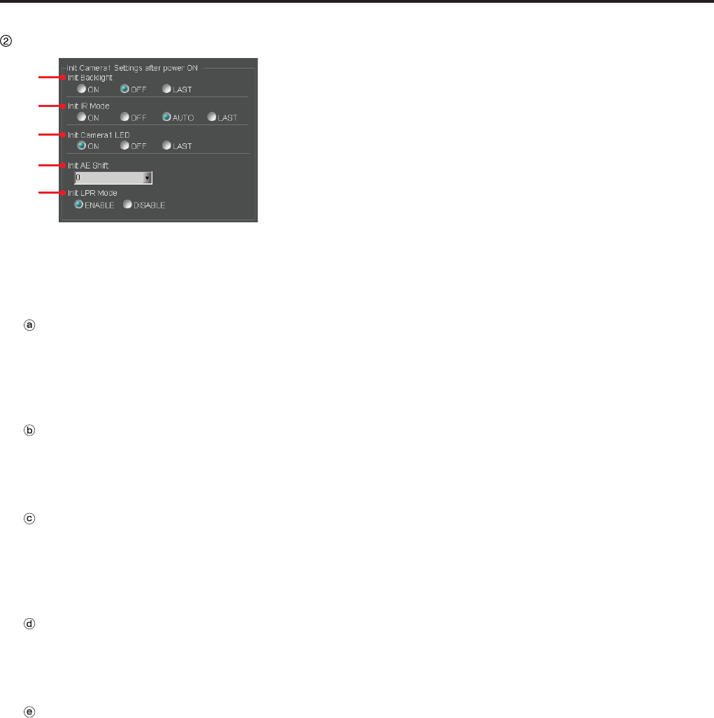
Init Camera1 Settings after power ON
ⓐ
ⓑ
ⓒ
ⓓ
ⓔ
The status of the color camera when it is turned on
can be set.
(See "Init Camera1 Settings after power ON,"
page 84.)
Init Backlight
Set the backlight compensation function setting
upon power-on of the Memory Card Video
Recorder.
Setting values: ON, OFF, LAST
Init IR Mode
Set the IR mode upon power-on of the Memory
Card Video Recorder.
Setting values: ON, OFF, AUTO, LAST
Init Camera1 LED
Set the status of the [REC] lamp on the camera
connected to the [CAMERA 1] connector on the
Memory Card Video Recorder upon power-on.
Setting values: ON, OFF, LAST
Init AE Shift
Set the brightness of images upon power-on of the
Memory Card Video Recorder.
Setting values: 2, 1, 0, -1, -2, LAST
Init LPR Mode
Set if the LPR mode is enabled or not upon power-
on of the Memory Card Video Recorder.
Setting values: ENABLE, DISABLE
Description of the Screen Displays (continued)
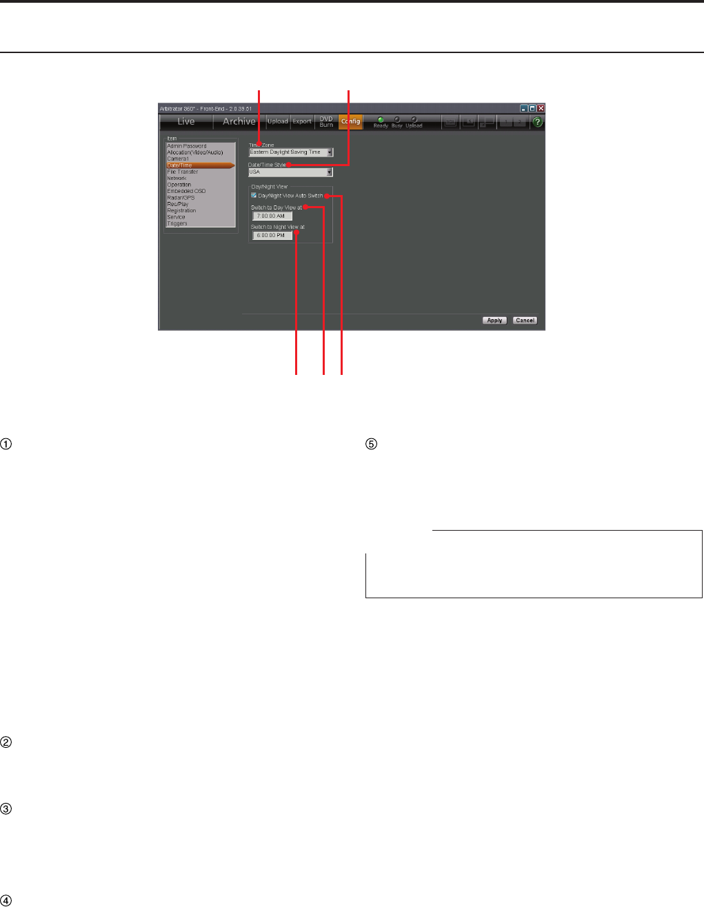
Date/Time screen
① ②
③④⑤
(See "Date/Time," page 86.)
Time Zone
Set the time zone.
Setting values:
Hawaii Standard Time
Yukon Standard Time
Yukon Daylight Saving Time
Pacic Standard Time
Pacic Daylight Saving Time
Mountain Standard Time
Mountain Daylight Saving Time
Central Standard Time
Central Daylight Saving Time
Eastern Standard Time
Eastern Daylight Saving Time
Atlantic Standard Time
Atlantic Daylight Saving Time
Asia Tokyo
Date/Time Style
Set the display pattern of date and time.
Setting values: ISO, USA
Day/Night View Auto Switch
Select if Day and Auto Switch Night views are
automatically switched or not. When a check mark
is placed in the box, Day/Night views are switched
automatically.
Switch to Day View at
Set the time when Night mode is changed to Day
mode.
Setting range: 00:00:00 AM-11:59:59 PM
Switch to Night View at
Set the time when Day mode is changed to Night
mode.
Setting range: 00:00:00 AM-11:59:59 PM
Note
Displayed time (12/24-hour system) depends on the
setting on your PC.
Description of the Screen Displays (continued)
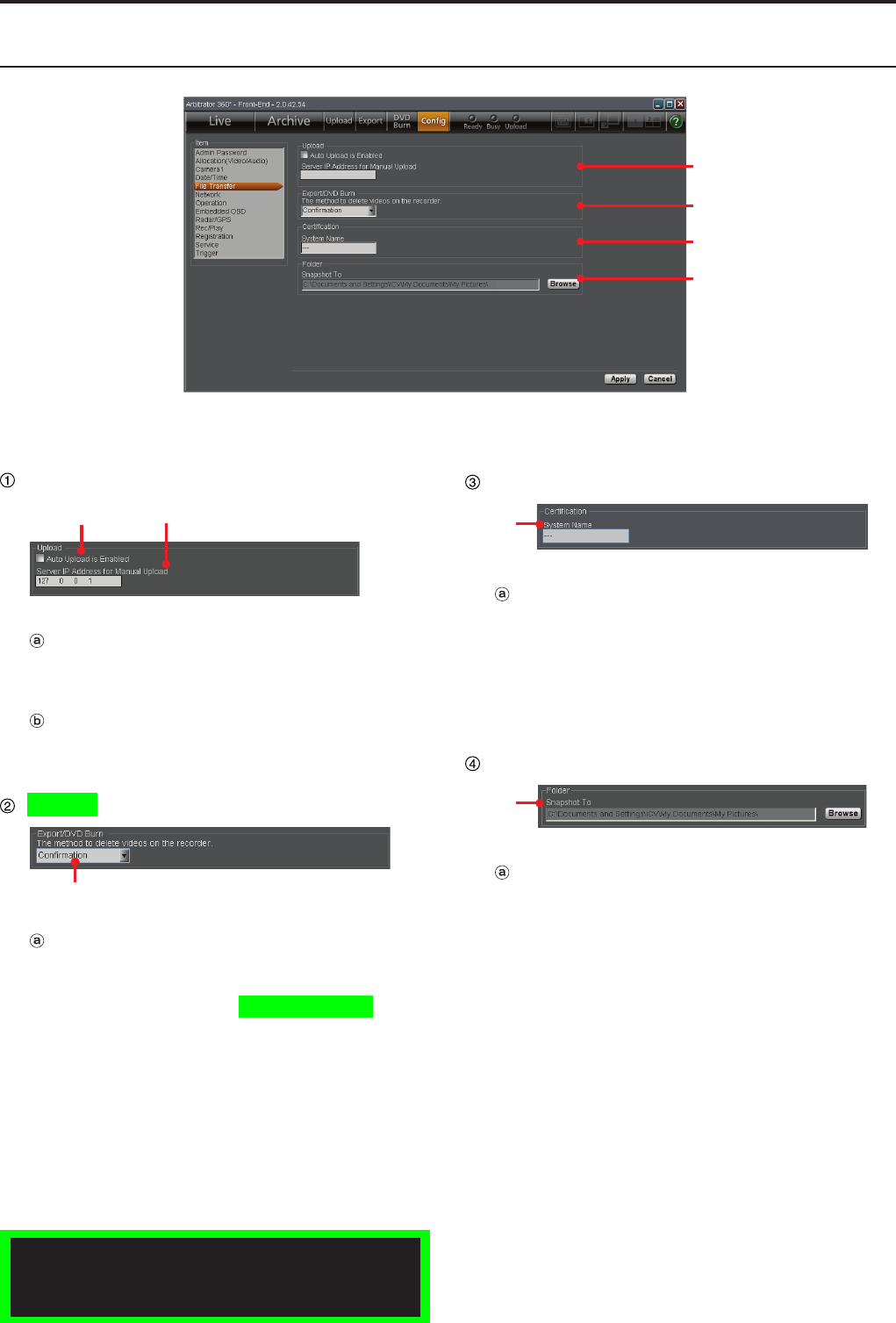
File Transfer screen
①
②
③
④
Exporting from the Front-End Application is not
available at present. Upgrading is scheduled for
the future.
(See "File Transfer," page 87.)
Upload
ⓐⓑ
Auto Upload is Enabled
Automatic uploading is enabled when a check mark
is placed in the box.
Server IP Address for Manual Upload
Set the IP address of the Back-End server for
manual uploading.
Export/DVD Burn
ⓐ
The method to delete videos on the
recorder
Select how to delete video les from the Memory
Card Video Recorder after data exporting or DVD
burning.
Setting values: Force, Conrmation
Certication
ⓐ
System Name
Set the system name of the Memory Card Video
Recorder within 50 characters. When the Recorder
directly communicates with the Back-End system,
the communications is enabled only when the
name set here and that registered in the Back-End
system are the same.
Folder
ⓐ
Snapshot To
Assign a folder to which snapshot les are to be
stored.
Description of the Screen Displays (continued)
(See "Network," page 89.)
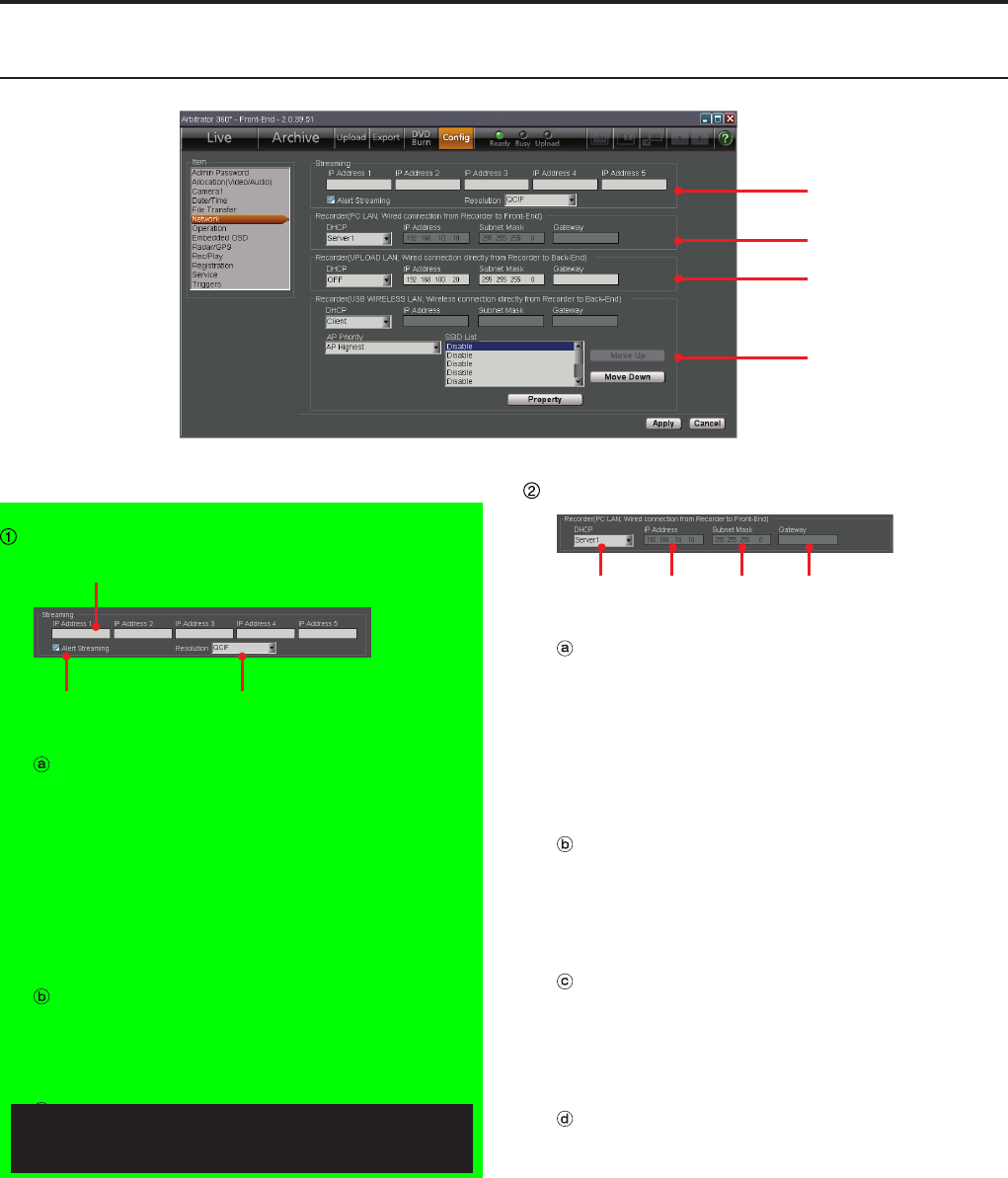
Streaming
ⓐ
ⓑⓒ
IP Address list
Set the IP Addresses of the Back-End server for
streaming. Up to 5 IP addresses can be registered.
The Front-End application periodically sends
packets to these IP addresses. The Back-End
server recognizes the sender of the received
packets as a streaming target. A Front-End
application can connect with a single Back-End
server at a time.
Alert Streaming
If a check mark is placed in the box, when
streaming is in progress in the Back-End
application, that is displayed on the screen.
Resolution
Set the resolution of the video in streaming.
Setting values: QCIF (176x112), CIF (352x240)
Recorder (PC LAN)
ⓐ ⓑ ⓒ ⓓ
DHCP
Set if the LAN port on the Memory Card Video
Recorder that is used for connection of the Front-
End application is to operate as a DHCP server or
not.
Setting values: OFF, Server1, Server2, Server3,
Server4
IP Address
Set the IP address for the LAN port on the Memory
Card Video Recorder that is used for connection of
the Front-End application.
This setting is enabled when DHCP is set to OFF.
Subnet Mask
Set the subnet mask for the LAN port on the
Memory Card Video Recorder that is used for
connection of the Front-End application.
This setting is enabled when DHCP is set to OFF.
Gateway
Set the gateway for the LAN port on the Memory
Card Video Recorder that is used for connection of
the Front-End application.
Network screen
①
②
③
④
Streaming is not available at present. Upgrading
is scheduled for the future.
Description of the Screen Displays (continued)
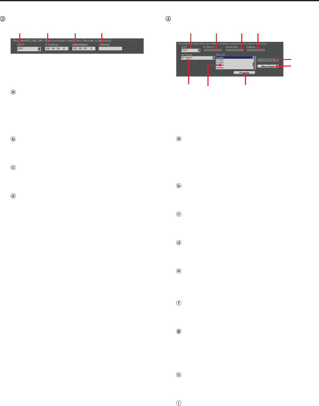
Recorder (UPLOAD LAN)
ⓐ ⓑ ⓒ ⓓ
The settings for the wired LAN port on the Memory
Card Video Recorder that is used for connection of
the Back-End application can be performed.
DHCP
Select if the IP address for the wired LAN port on
the Memory Card Video Recorder will be obtained
from the DHCP server or not.
Setting values: OFF, Client
IP Address
Set the IP address. This setting is enabled when
DHCP is set to OFF.
Subnet Mask
Set the subnet mask. This setting is enabled when
DHCP is set to OFF.
Gateway
Set the default gateway. This setting is enabled
when DHCP is set to OFF.
Recorder (USB WIRELESS LAN)
ⓐ ⓑ ⓒ ⓓ
ⓔⓕⓖ
ⓗ
ⓘ
The settings for the USB wireless LAN port on
the Memory Card Video Recorder that is used for
connection of the Back-End application can be
performed.
DHCP
Select if the IP address for the USB wireless LAN
port on the Memory Card Video Recorder will be
obtained from the DHCP server or not.
Setting values: OFF, Client
IP Address
Set the IP address. This setting is enabled when
DHCP is set to OFF.
Subnet Mask
Set the subnet mask. This setting is enabled when
DHCP is set to OFF.
Gateway
Set the default gateway. This setting is enabled
when DHCP is set to OFF.
AP Priority
Set the priority of connections to the access points.
Setting values: AP Highest, Random
SSID List
For displaying the SSIDs for the access points. Up
to 10 SSIDs are displayed.
Property button
For editing data of the access point selected in the
SSID List. Click to display the Access Point Setting
screen.
(See "Access Point Setting screen," page 37.)
Move Up button
For raising the priority of the connection order for
access points.
Move Down button
For lowering the priority of the connection order for
access points.
Description of the Screen Displays (continued)
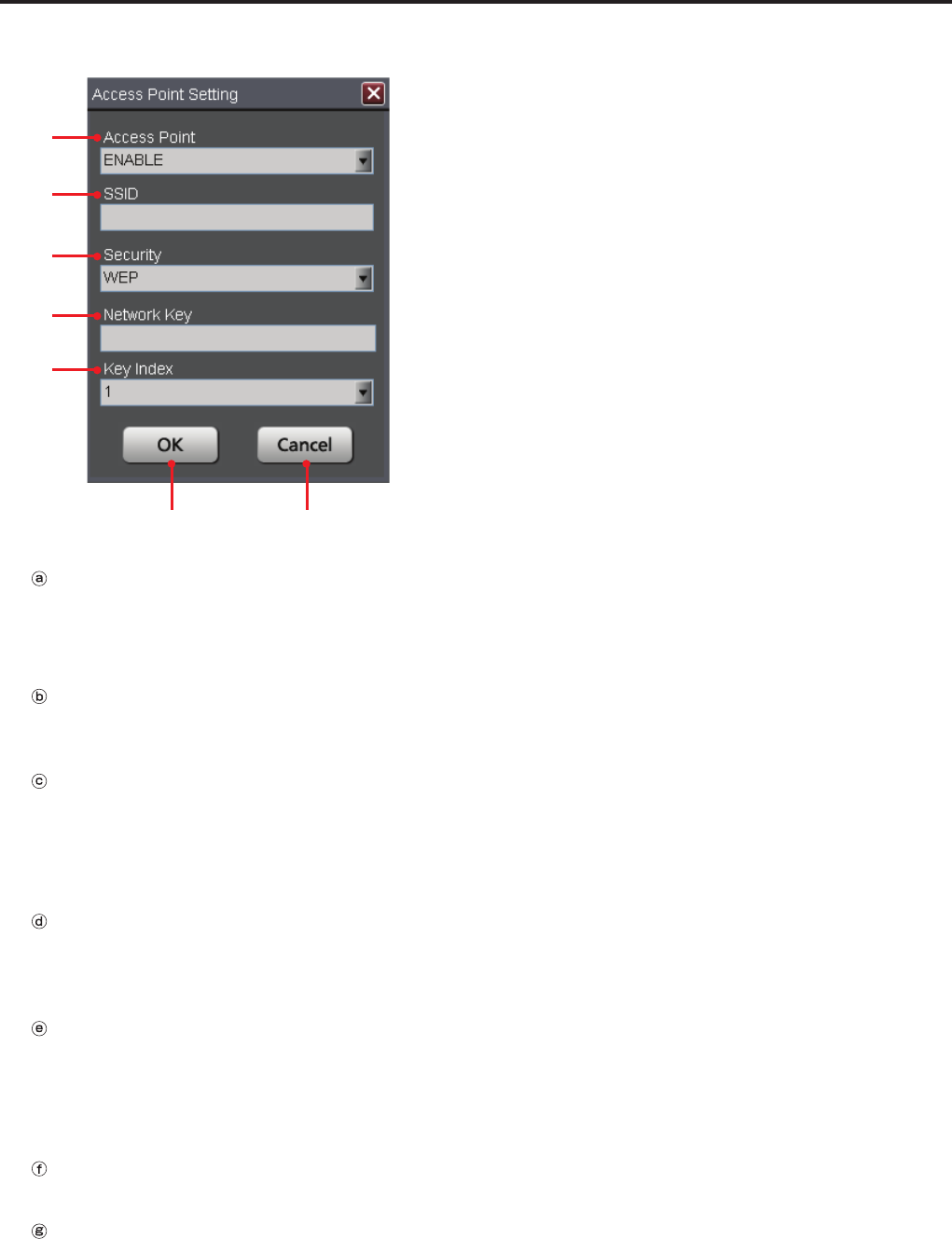
Access Point Setting screen
ⓐ
ⓑ
ⓒ
ⓓ
ⓔ
ⓕ ⓖ
Access Point
Select if the access point settings are enabled or
not.
Setting values: ENABLE, DISABLE
SSID
Set the SSID for the wireless LAN module
connected to the Memory Card Video Recorder.
Security
Set the encryption method for the wireless LAN
module connected to the Memory Card Video
Recorder.
Setting values: WEP, WPA/WPA2-PSK, NONE
Network Key
Set the network key for the wireless LAN module
connected to the Memory Card Video Recorder
when Security is set to WEP or WPA.
Key Index
Set the network key index for the wireless LAN
module connected to the Memory Card Video
Recorder when Security is set to WEP.
Setting values: 1, 2, 3, 4
OK button
For registering the settings to the SSID list.
Cancel button
For canceling the settings.
Description of the Screen Displays (continued)
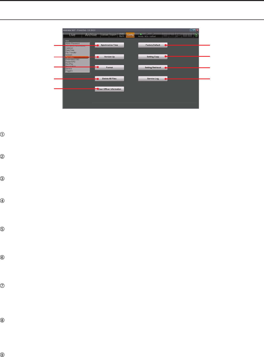
Operation screen
①
②
③
④
⑤
⑥
⑦
⑧
⑨
(See "Operation," page 92.)
Synchronize Time button
For synchronizing the clock of the Memory Card
Video Recorder with that of the PC.
Version Up button
For updating the rmware of the Memory Card
Video Recorder.
Format button
For formatting all SDHC Memory Cards loaded in
the Memory Card Video Recorder.
Delete All Files button
For deleting all video les stored in the SDHC
Memory Cards loaded in the Memory Card Video
Recorder.
Clear Ofcer Information button
For deleting the data for Ofcer1, Ofcer2,
VehicleID, Area, Unit, Agency, and Shift from the
Memory Card Video Recorder.
Factory Default button
For initializing the current setting data of the
Memory Card Video Recorder and the Front-End
application.
Setting Copy button
For exporting the current setting data of the
Memory Card Video Recorder and the Front-
End application to external media, such as a USB
memory device.
Setting Retrieval button
For copying back the setting data that have been
exported to the external media with the Setting
Copy function onto the Memory Card Video
Recorder and the Front-End application.
Service Log button
The operation log of the Memory Card Video
Recorder can be exported to external media.
Description of the Screen Displays (continued)
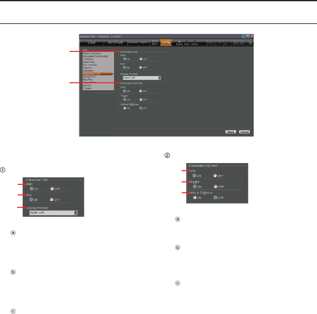
Embedded OSD screen
①
②
(See "Embedded OSD," page 97.)
Embedded OSD
ⓐ
ⓑ
ⓒ
Main
Select if the Embedded OSD is displayed on the
main video or not.
Setting values: ON, OFF
Sub
Select if the Embedded OSD is displayed on the
sub video or not.
Setting values: ON, OFF
Display Position
Set the Embedded OSD display position.
Setting values: Upper-Left, Upper-Right,
Bottom-Left, Bottom-Right
Embedded OSD Item
ⓐ
ⓑ
ⓒ
Time
Select if time is displayed as an Embedded OSD.
Setting values: ON, OFF
Trigger
Select if trigger indications are to be displayed as
Embedded OSD.
Setting values: ON, OFF
VehicleID@Area
Select if the vehicle ID and area are to be displayed
as Embedded OSD.
Setting values: ON, OFF
0
Description of the Screen Displays (continued)
1
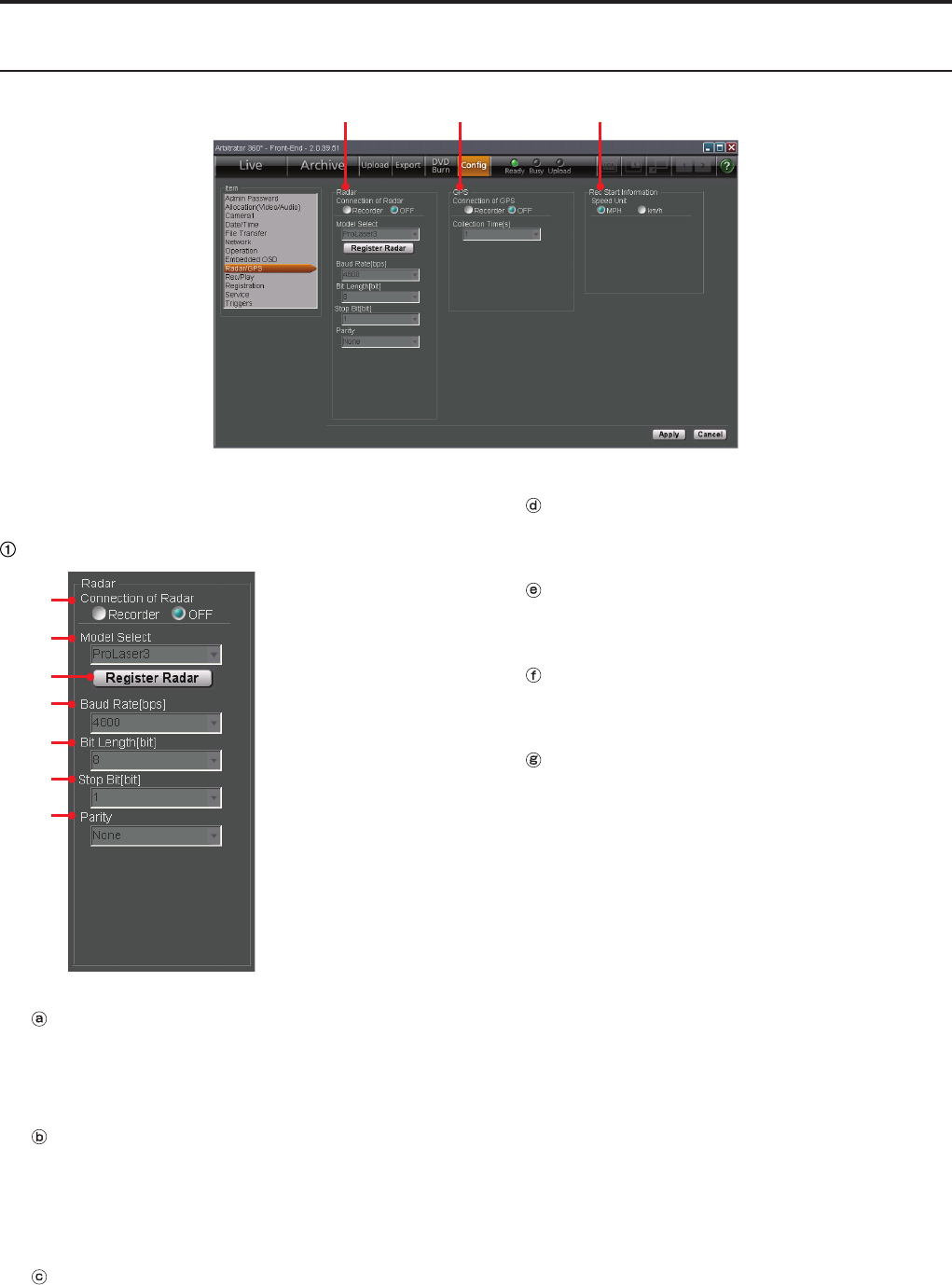
Radar/GPS screen
① ② ③
(See "Radar/GPS," page 98.)
Radar
ⓐ
ⓑ
ⓒ
ⓓ
ⓔ
ⓕ
ⓖ
Connection of Radar
Select if a radar gun is connected to the Memory
Card Video Recorder or not.
Setting values: Recorder, OFF
Model Select
Select the model name of the connected radar gun
from the drop-down list.
Setting values: ProLaser3, STALKER_DUAL,
GOLDEN_EAGLE_II
Register Radar button
For registering the radar gun library that has been
stored in a USB memory device to the Memory
Card Video Recorder.
Baud Rate[bps]
The baud rate of the serial communication is
displayed when a radar gun is connected.
Bit Length[bit]
The bit length of the serial communication is
displayed when a radar gun is connected.
Stop Bit[bit]
The stop bit length of the serial communication is
displayed when a radar gun is connected.
Parity
The parity of the serial communication is displayed
when a radar gun is connected.
0
1
Description of the Screen Displays (continued)
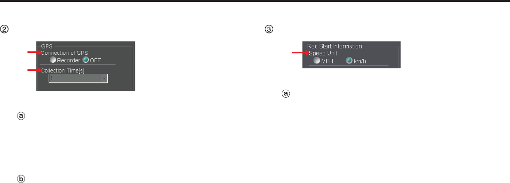
GPS
ⓐ
ⓑ
Connection of GPS
Select if the GPS is connected to the Memory Card
Video Recorder or not.
Setting values: Recorder, OFF
Collection Time[s]
Select an interval of collecting data from the GPS.
Setting values: 1, 2, 5, 10 seconds
Rec Start Information
ⓐ
Speed Unit
Select the speed unit.
Setting values: MPH, km/h
Description of the Screen Displays (continued)
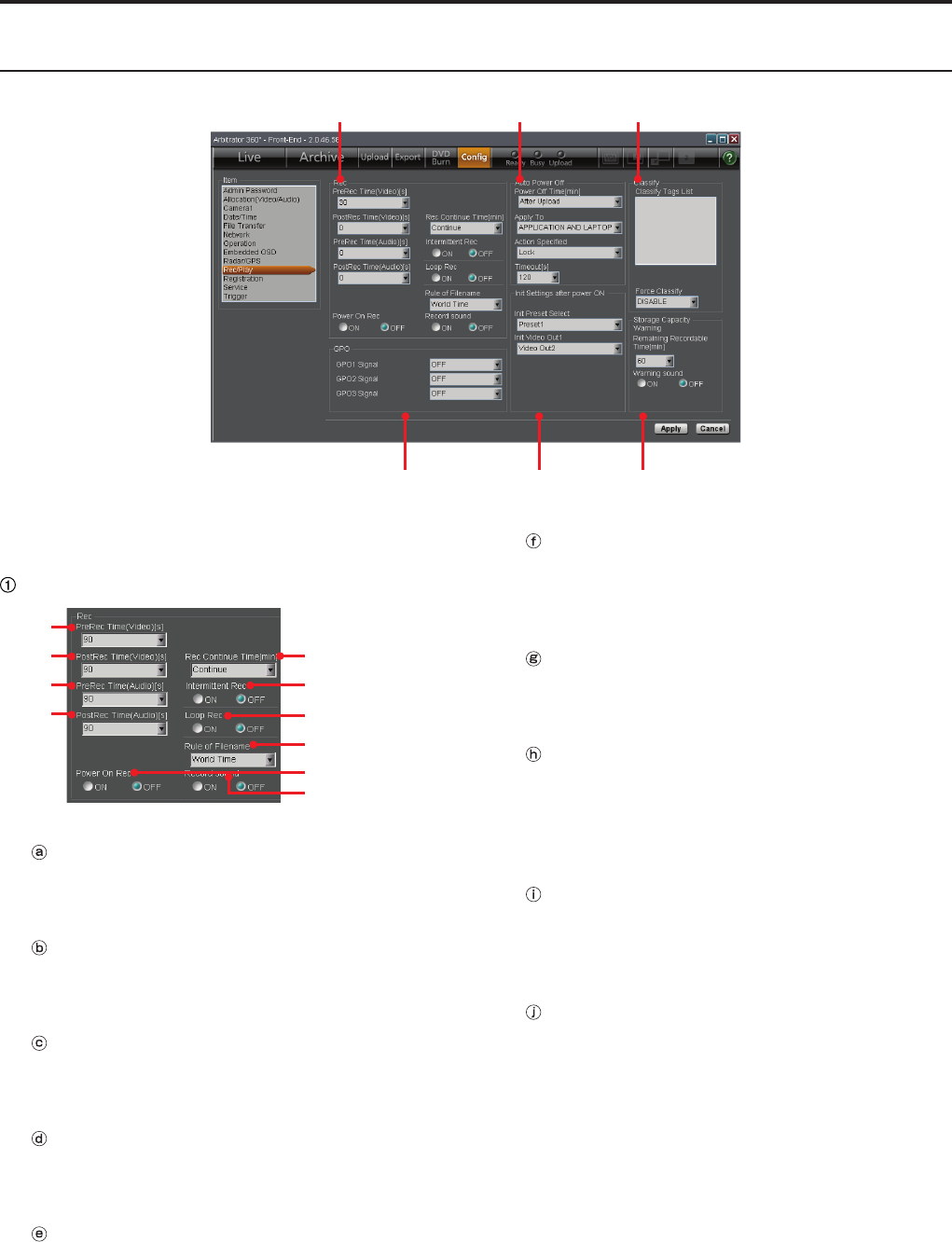
Rec/Play screen
①
④ ⑤ ⑥
② ③
(See "Rec/Play," page 101.)
Rec
ⓐ
ⓑ
ⓒ
ⓓ
ⓔ
ⓕ
ⓖ
ⓗ
ⓘ
ⓙ
PreRec Time(Video)[s]
Select the pre-recording time for video.
Setting values: 0, 10, 20, 30, 60, 90 seconds
PostRec Time(Video)[s]
Select the post-recording time for video.
Setting values: 0, 10, 20, 30, 60, 90 seconds
PreRec Time(Audio)[s]
Select the pre-recording time for audio.
Setting values: 0, 3, 10, 20, 30, 60, 90 seconds
PostRec Time(Audio)[s]
Select the post-recording time for audio.
Setting values: 0, 3, 10, 20, 30, 60, 90 seconds
Rec Continue Time[min]
Select the recording duration.
Setting values: Continue, 1, 2, 5, 10, 15, 20, 30,
60, 90 minutes
Intermittent Rec
Select if the intermittent recording mode is enabled
or not.
Setting values: ON, OFF
Loop Rec
Select if the loop recording mode is enabled or not.
Setting values: ON, OFF
Rule of Filename
Select the time system to be used in the video
lename that is recorded the Memory Card Video
Recorder.
Setting values: World Time, Local Time
Power On Rec
Select if recording is started when the Memory
Card Video Recorder is turned on.
Setting values: ON, OFF
Record sound
Select if a beep sounds every minute during
recording.
Setting values: ON, OFF
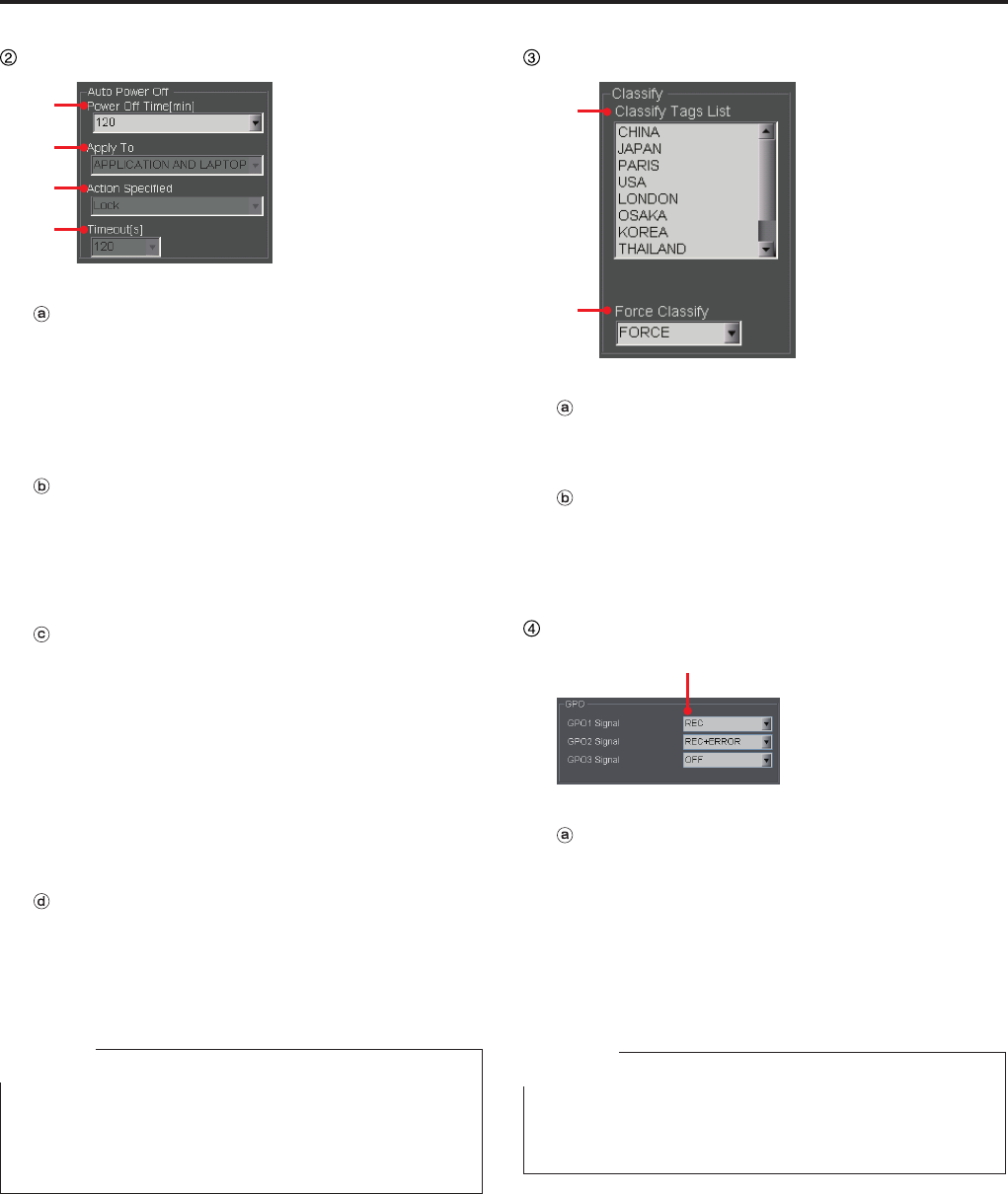
Description of the Screen Displays (continued)
Auto Power OFF
ⓐ
ⓑ
ⓒ
ⓓ
Power Off Time[min]
Select the time required from the ACC is turned off
up to the Memory Card Video Recorder is turned
off.
Setting values: 0, 10, 20, 30, 60, 90, 120, 180
minutes, After Upload
Apply To
When Power Off Time is set to After Upload, select
which one's uploading is to be observed.
Setting values: APPLICATION ONLY, LAPTOP
ONLY, APPLICATION AND LAPTOP
Action Specied
When Power Off Time is set to After Upload, select
which action is to be taken by the subject (s) after
uploading is completed.
Setting values:
Setting values depend on the setting of Apply To.
APPLICATION ONLY: Close
LAPTOP ONLY: Lock Stand by
APPLICATION AND LAPTOP: Lock, Log off,
Shutdown, Stand by
Timeout[s]
When Power Off Time is set to After Upload, select
the time required from the specied action is taken
till the Memory Card Video Recorder is turned off.
Setting values: 30, 60, 90, 120 seconds
Note
When the vehicle’s ignition switch is set to ACC-OFF with
Upload Mode on the File Transfer screen in Cong setup
set to MANUAL and Power Off Time on the Rec/Play
screen set to AUTO, uploading will start automatically.
Classify
ⓐ
ⓑ
Classify Tag List
The names of the registered classify tags are
displayed. Up to 50 classify tags can be registered.
Force Classify
Set if the user is forced to add classify information
at the end of recording.
Setting values: DISABLE, ENABLE, FORCE
GPO
ⓐ
GPO1 Signal, GPO2 Signal, GPO3 Signal
Select if the recording and recording error statuses
are output to GPO 1, 2, and 3.
Setting values:
GPO1 Signal, GPO2 Signal: OFF, REC,
ERROR, REC+ERROR
GPO3 Signal: OFF, REC
Note
The functions of GPO1, GPO2, and GPO3 can be
changed with settings. GPO4 always outputs the power
status of the recorder, and has no setting.
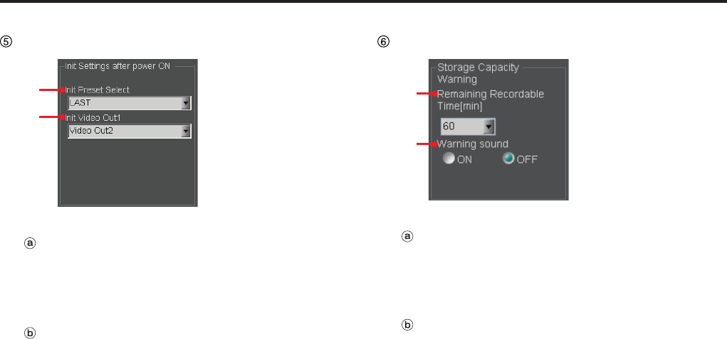
Description of the Screen Displays (continued)
Init Settings after power ON
ⓐ
ⓑ
Init Preset Select
Select a preset applied when the Memory Card
Video Recorder is turned on.
Setting values: Preset1, Preset2, Preset3, LAST
Init Video Out1
Select a signal to be output from the [VIDEO OUT
1] connector of the Memory Card Video Recorder
when it is turned on.
Setting values: CAM1, CAM3, Video Out2, LAST
Storage Capacity Warning
ⓐ
ⓑ
Remaining Recordable Time[min]
A warning sounds when the remaining recordable
time becomes shorter than the value set here.
Setting values: 30, 60, 90 (minutes)
Warning sound
Select if a short beep is to sound twice every 30
seconds when the remaining recordable time
becomes shorter than the set value.
Setting values: ON, OFF
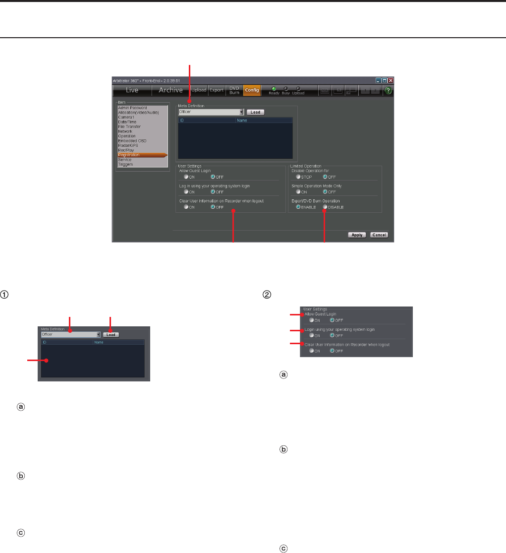
Description of the Screen Displays (continued)
Registration screen
①
② ③
(See "Registration," page 105.)
Meta Denition
ⓐⓑ
ⓒ
Meta Denition
Select the type of meta denition to be registered to
the Memory Card Video Recorder.
Setting values: Administrator, Ofcer, Classify,
Agency, Unit, Shift, Area, VehicleID
Load button
For loading data specied at Meta Denition from
the USB memory device and registering the data to
the Memory Card Video Recorder.
Meta Denition list
The meta denition data loaded from the USB
memory device are displayed on this list.
User Settings
ⓐ
ⓑ
ⓒ
Allow Guest Login
Select if login of a user who has not been registered
in the Back-End server or the Memory Card Video
Recorder is permitted or not.
Setting values: ON, OFF
Login using your operating system
login
When set to ON, if the current login user name
to the PC is the same as that to the Front-End
application, the login screen with the password
entered will be displayed.
Setting values: ON, OFF
Clear User Information on Recorder
when logout
Select if the user information of the Memory Card
Video Recorder is deleted upon logoff.
Setting values: ON, OFF

Description of the Screen Displays (continued)
Limited Operation
ⓐ
ⓑ
ⓒ
Disable Operation for
Set the operation prohibited by a user.
Setting values: STOP, OFF
Simple Operation Mode Only
When set to ON, a user can use only Simple
Operation mode.
Regardless of this setting, the administrator can use
both Simple Operation mode and Full Operation
mode.
The default setting is OFF.
Setting values: ON, OFF
Export/DVD Burn Operation
Set if export and DVD burn is permitted by a user.
Setting values: ENABLE, DISABLE
Exporting from the Front-End Application is not
available at present. Upgrading is scheduled for
the future.
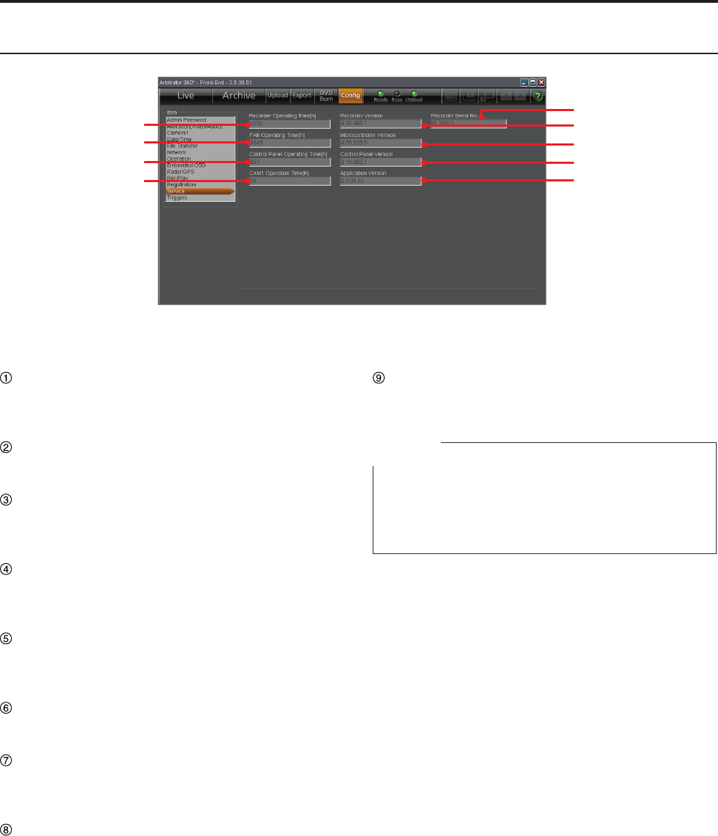
Description of the Screen Displays (continued)
Service screen
①
②
③
④
⑨
⑤
⑥
⑦
⑧
(See "Service," page 109.)
Recorder Operating Time[h]
The total operation time of the Memory Card Video
Recorder is displayed.
FAN Operating Time[h]
The total operation time of the fan is displayed.
Control Panel Operating Time[h]
The total operation time of the Remote Control
Panel is displayed.
CAM1 Operation Time[h]
The total operation time of the color camera is
displayed.
Recorder Version
The version of the rmware for the Memory Card
Video Recorder is displayed.
Microcontroller Version
The version of the Microcontroller is displayed.
Control Panel Version
The version of the remote control panel is
displayed.
Application Version
The version of the Front-End application is
displayed.
Recorder Serial No.
The serial number of the Memory Card Video Recorder
is displayed.
Note
When the AG-CPD15P or AG-CPD10CRUP Memory
Card Video Recorder is used, the BIOS Creation Date
is displayed to show the date and time when BIOS was
created.
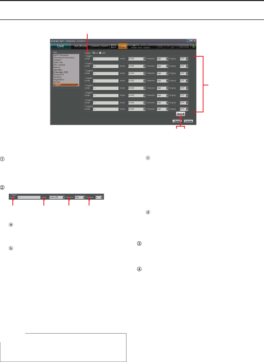
Description of the Screen Displays (continued)
Triggers screen
①
②
③ ④
(See "Triggers," page 110.)
Trigger
Set if the GPI trigger function is used or not.
Setting values: ON, OFF
Trigger1- Trigger16
ⓐ ⓑ ⓒ ⓓ
Name
Specify the name of a GPI trigger with up to 15
characters.
Action
Select the action of a GPI trigger.
Setting values:
<Trigger 1-16>
NONE, REC, STOP, AUTOZOOM, CAM1LED,
Preset1, Preset2, Preset3, Preset1Rec,
Preset2Rec, Preset3Rec, AUDIO2ON,
AUDIO2MUTE
<Trigger 15-16>
TGT(REC), TGT(P1REC), TGT(P2REC),
TGT(P3REC), OWN(REC), OWN(P1REC),
OWN(P2REC), OWN(P3REC)
Note
TGT and OWN can be set to either Trigger 15 or Trigger
16, but not to both of them.
Detection
Select the condition for a GPI trigger to action.
Setting values:
<Trigger 1-16>
Low, High, Both, Level High, Level Low
<Trigger 15-16>
OFF, 1, 2, . . . 200
Display
Select a trigger code that is to be displayed on a
video.
Setting values: A to Z, –, OFF
Next button
For displaying the Setup screens for Trigger9 to
Trigger16.
Prev button
For displaying the Setup screens for Trigger1 to
Trigger8.
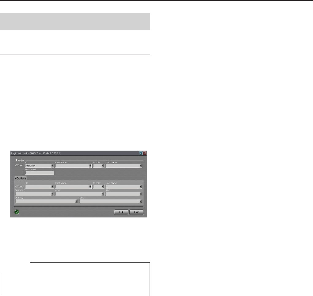
Operations
Startup and Termination
Starting up
A user named "Arbitrator" and having the password
"admin" have been registered as default. When you
start the Front-End Application for the rst time after
purchasing, the registered name is displayed in
Ofcer1.
1. Turn on the PC and the Memory Card Video
Recorder.
2. Click on the Front-End application icon on
the desktop.
The Login screen is displayed.
If the meta denition data in which registered
ofcers data are included are loaded in the Memory
Card Video Recorder, the ID(s) and the name(s)
will be displayed.
Note
If remote updating is being processed, the processing
screen may be displayed.
3. If the meta denition data are loaded, select
a user ID from the dropdown list of Ofcer 1.
The name for Ofcer 1 is displayed.
If the meta denition data are not loaded, enter the
user ID and name.
4. Enter the password.
5. Click on [OK].
The Main screen in Live mode is displayed.
Option settings
If data for the Option items have already been
registered on the list, select options from the dropdown
lists. If no data have been registered on the list, enter
the necessary data.
1. Set Ofcer 2 in the same manner as with
Ofcer 1, if necessary.
2. Set the vehicle ID in Vehicle ID.
3. Set the area in Area.
4. Set the unit in Unit.
5. Set the police agency in Agency.
6. Set the shiftwork pattern in Shift.
7. Click on [OK].
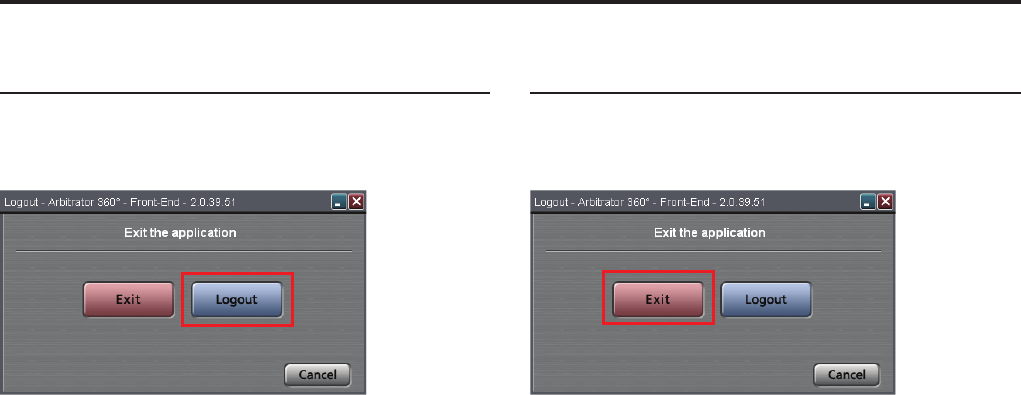
0
Operations (continued)
1
Restarting
1. Click on the Close button on the screen.
The Shutdown screen is displayed.
2. Click on [Logout].
The Login screen is displayed.
3. Perform the necessary settings.
(See "Starting up," page 49.)
This software restarts, and the Main screen in Live
mode will be displayed.
Terminating
1. Click on the Close button on the screen.
The Shutdown screen is displayed.
2. Click on [Exit].
This software is terminated.
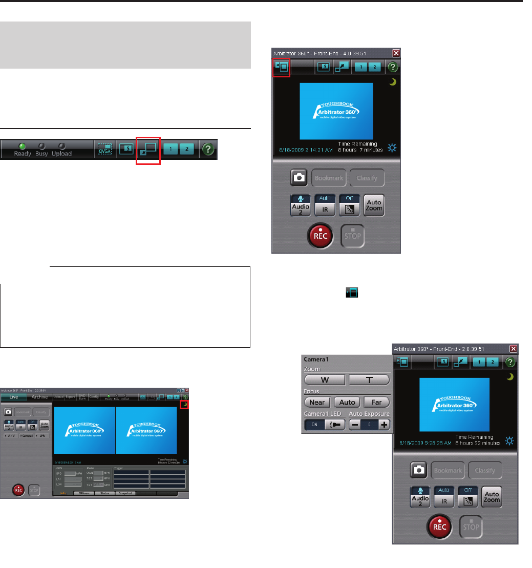
0
1
Operations (continued)
Switching and Adjusting
Display Mode
Switching Full/Simple Operation
mode
Full Operation mode, in which all the functions are
available, and Simple Operation mode, in which
available functions are limited are provided. These
two modes can be switched, using the Full/Simple
Operation mode switch button.
Note
If "Simple Operation Mode Only" is set to ON in the
Registration screen in Administrator Setup, a user cannot
use Full Operation mode. (See "Limited Operation," page
108.)
Full Operation mode
Simple Operation mode
Camera control button
If you click on [ ] button, the Camera1 tab is
displayed.
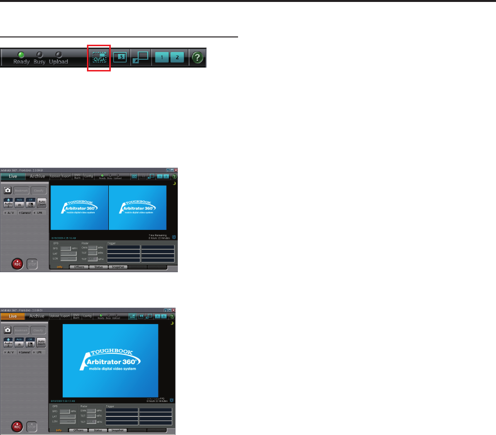
Operations (continued)
Switching the QVGA and VGA sizes
In Full Operation mode, either of the QVGA or VGA
display size can be selected, using the QVGA or VGA
switch button.
QVGA display
VGA display
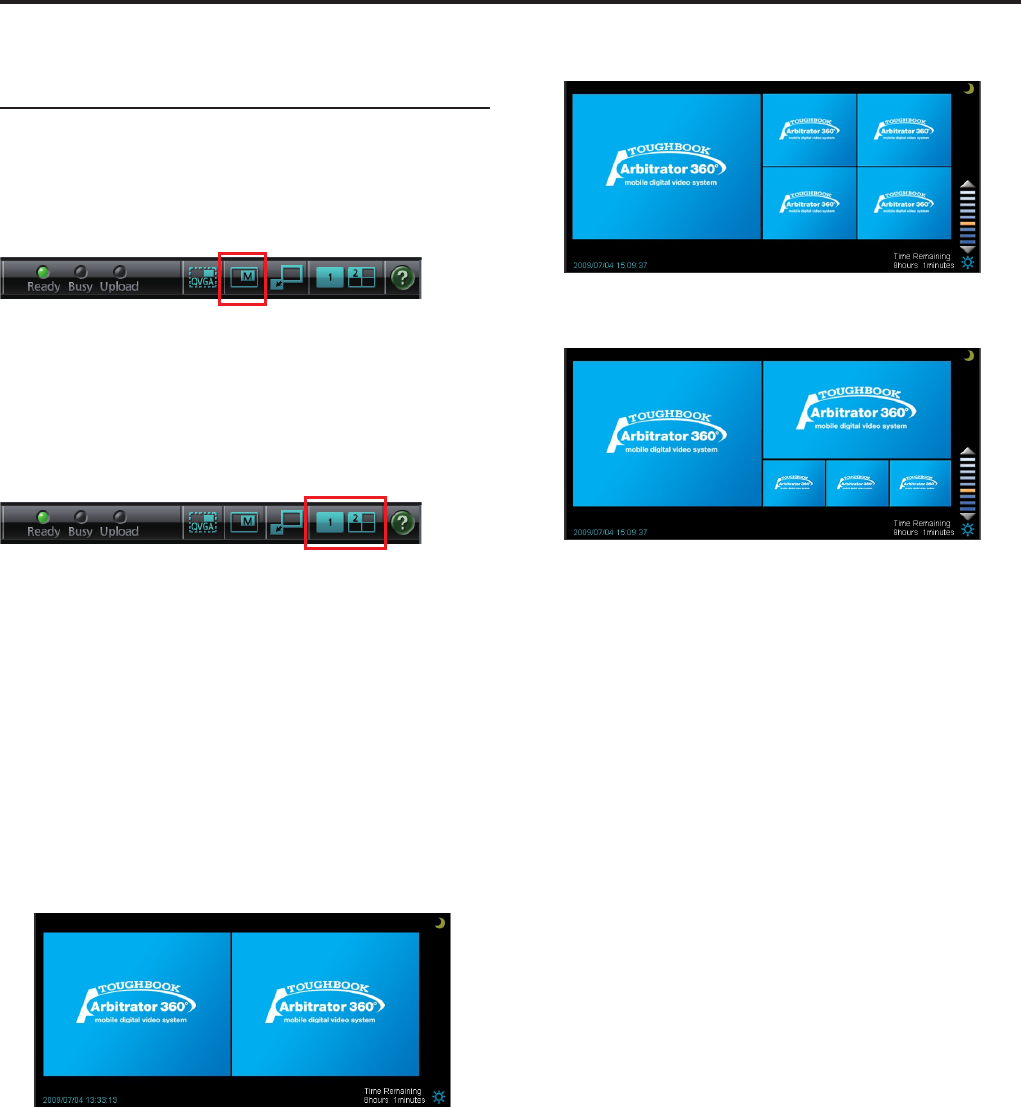
Operations (continued)
Switching the Main video and Sub
video
With the QVGA size Full Operation mode screen, either
1-screen or 2-screen display can be selected.
1-screen display
With 1-screen display, either the main or sub video is
displayed. Each click on the Main/Sub video switch
button changes the main and sub videos alternately.
2-screen display
With 2-screen display, the main and sub videos are
simultaneously displayed. On the sub-video screen, 1
video or 4 videos can be displayed. The 4 videos can
be displayed in either QUAD or PANORAMA size.
The settings for the cameras allocation and display
pattern in the 2-screen display can be performed on the
Allocation (Video/Audio) screen in Administrator Setup.
Three display pattern settings--Preset 1, Preset 2, and
Preset 3--are available.
Use the Preset switch button for setting.
(See "Preset Settings," page 81.)
1 sub-video display
4 sub-video display in QUAD size
4 sub-video display in PANORAMA size
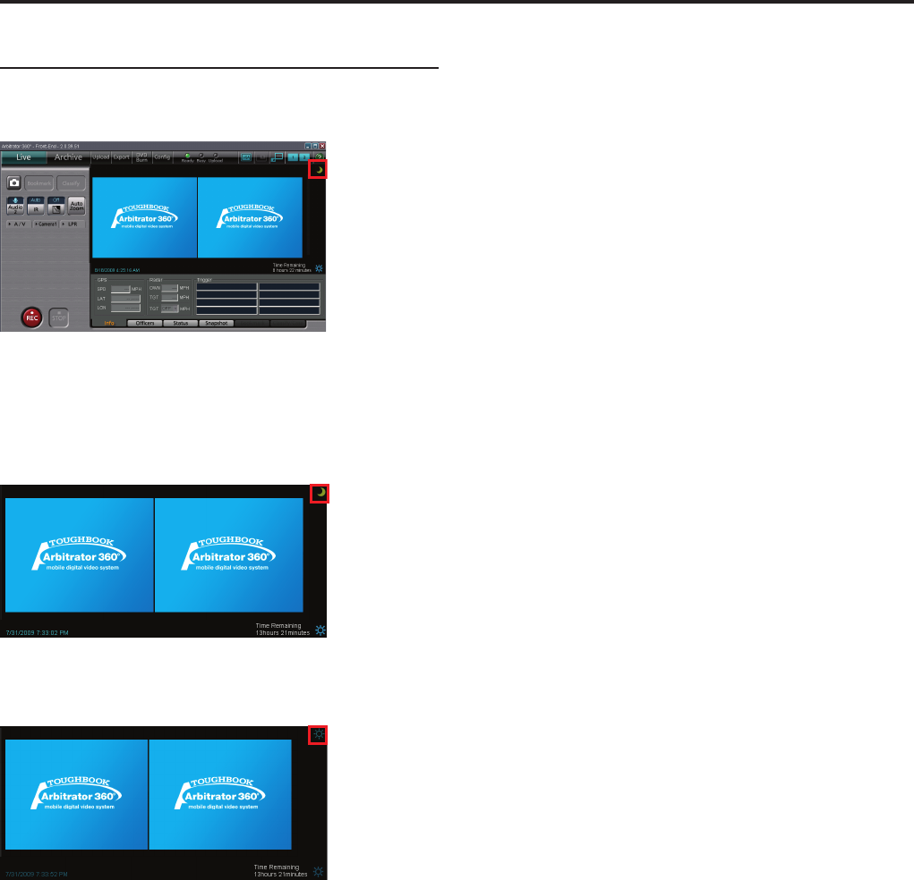
Operations (continued)
Switching Day and Night modes
The screen image can be switched between Day mode
and Night mode.
Click on [Day/Night].
Each click on this button changes the screen between
Day and Night modes.
Day mode
Night mode
The entire screen will become darker in Night mode.
Automatic switching of Day/Night modes
On the Date/Time screen in Administrator Setup, place
a check mark in the box for Day/Night View Auto
Switch. The Day and Night modes are automatically
switched at a specied time.
(See "Day/Night View," page 86.)
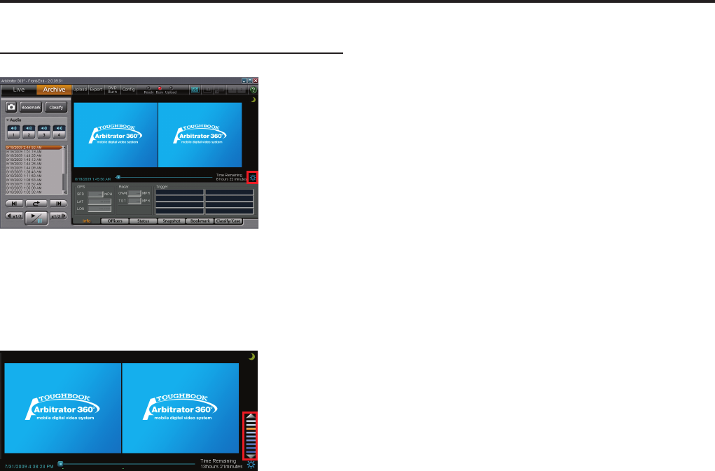
Operations (continued)
Adjusting image brightness
Click on [Brightness adjustment].
The current brightness level will be displayed. You can
adjust the brightness of the entire display.
Clicking on [▲] button makes the video display brighter,
and clicking on [▼] button makes it darker.
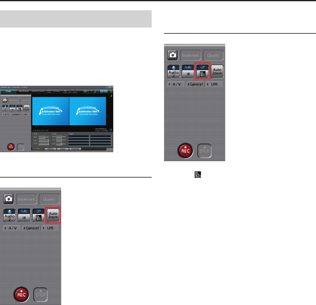
Operations (continued)
Viewing a Live Video
Upon startup of this software, the Main screen is
displayed in Live mode. The images currently shot by
the cameras can be viewed. The display size can be
switched, using the button on the toolbar.
(See "Switching and Adjusting Display Mode,"
page 51.)
Zooming in live mode
Click on [Auto Zoom].
The camera zooms into the target magnication,
stops for a while, then zooms out to the preset end
magnication. If the camera is at a zoom position with a
larger magnication than the target magnication when
this button is clicked, the camera zooms out to the
target magnication rst.
Making a backlit image easier to
view
Click on [ ].
The darker part of a backlit image becomes easier to
view.
Each time this button is clicked, "On" and "Off" are
switched alternately. The current setting is displayed on
the upper part of the button.
Normally, set it to "Off."
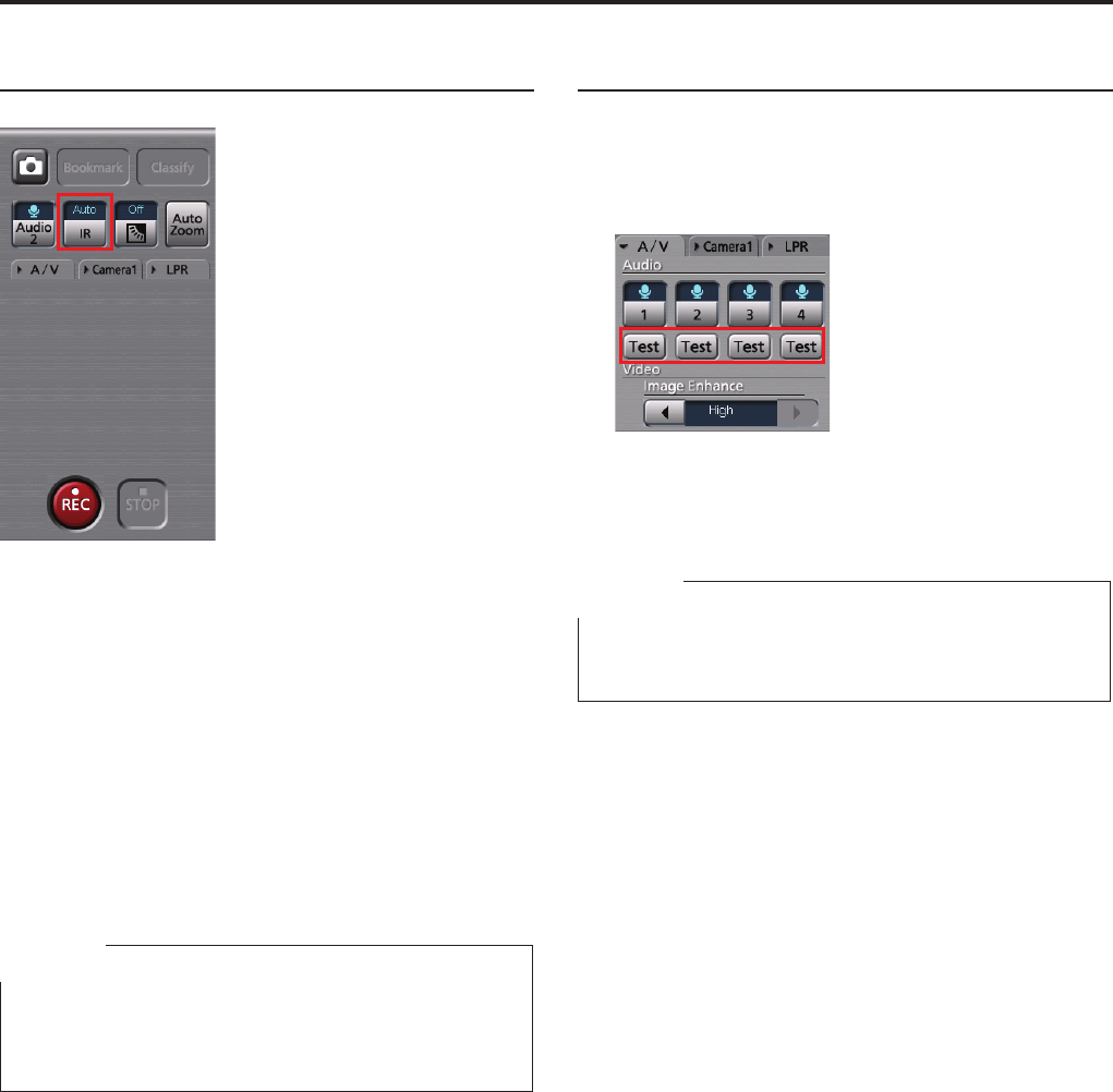
Operations (continued)
Making a dark image easier to view
Click on [IR].
A dark video image becomes easier to view with
infrared imaging.
Each time this button is clicked, "Auto," "On," and "Off"
are switched. The current setting is displayed on the
upper part of the button.
Normally, set it to "Auto."
Auto: Automatically changes IR mode depending
on ambient brightness.
On: Sets IR mode to On.
Off: Sets IR mode to Off.
Note
You can make a video image further brighter with image
enhancing. (See "Compensating image brightness,"
page 58.)
Checking audio
If a live video is displayed without sound, you can
check sound with the following procedures.
1. Click on the A/V tab.
2. Hold [Test] pressed.
While this button is held pressed, sound of the
corresponding audio channel can be heard.
Note
Depending on the audio setting, large sound may be
kept output. In such a case, lower the audio volume.
For users of Windows Vista
If the [Test] button does not function smoothly, it may
be improved by disabling “Press and hold”.
1. Click on [Start].
2. Select Control Panel.
3. Double-click on Pen and Input Devices.
4. Select the Touch tab.
5. Select “Press and hold” in Touch action.
6. Click on [Setting].
7. Uncheck the “Enable press and hold for
right-clicking”.
8. Click on [OK].
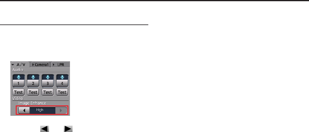
Operations (continued)
Compensating image brightness
You can adjust the brightness of dark video parts in the
main video.
1. Click on the A/V tab.
2. Click on [ ] or [ ] of Video Image
Enhance.
Off: No video image enhancing
Low: Low video image enhancing
High: High video image enhancing
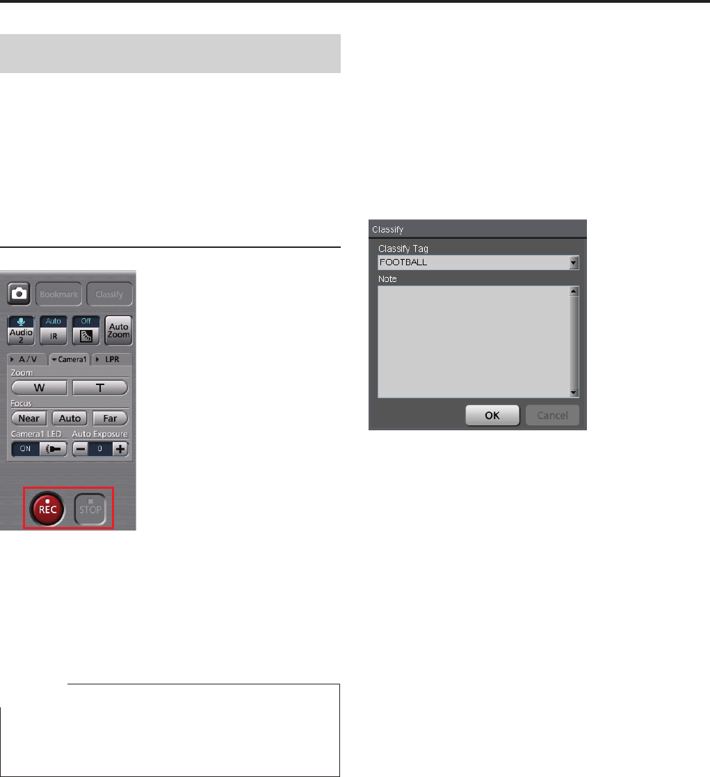
Operations (continued)
Recording
You can record not only the main video, but also the
main and sub videos simultaneously. As sub videos,
video signals from one camera, as well as those from
4 cameras, can be recorded in QUAD or PANORAMA
size.
(See "Switching and Adjusting Display Mode,"
page 51.)
Starting and stopping recording
Starting recording
Click on [REC].
The [REC] lamp on the color camera will light.
While recording, "REC" is indicated on the display, and
a red frame appears around the video.
Note
It is possible to disable the [REC] lamp.
(See "Turning off the [REC] lamp of the color camera
during recording," page 61.)
To start recording upon power-on
Recording starts upon power-on if PowerOn Rec is set
to ON on the Rec/Play screen in Administrator Setup.
(See "Rec," page 101.)
To stop recording
Click on [STOP].
Recording stops.
Setting the classify information
The Classify input screen is displayed when you click
on the [STOP] button if the following settings are made
on the Rec/Play screen in Administrator Setup and the
classify tags have been registered in the Front-End
application or the Memory Card Video Recorder:
Setting of Force Classify: FORCE or ENABLE
(See "Classify," page 104.)
Setting of Loop Rec: OFF
(See "Rec," page 101.)
1. Select a classify tag from the dropdown
list.
2. Enter a note for classify information in the
Note eld.
3. Click on [OK].
To close the screen without entering classify
information
You can close the Classify screen without entering
classify information if Force Classify is set to ENABLE.
Click on [Cancel]. Then the classify information is not
entered.
•
•
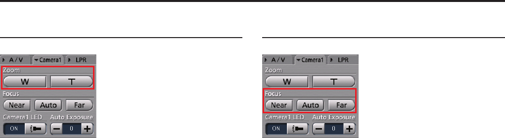
0
Operations (continued)
1
Zooming in record mode
Zooming can be controlled with the [Zoom] button on
the Camera1 tab.
To zoom out
Hold the [W] button pressed.
Release the button when the zoomed image of your
preference is displayed.
To zoom in
Hold the [T] button pressed.
Release the button when the zoomed image of your
preference is displayed.
Focusing
Focusing can be controlled with the [Focus] button on
the Camera1 tab.
Automatic adjustment
Click on [Auto].
With the automatic focus function, focusing is
performed automatically.
Manual adjustment
If the target is out of focus with the automatic focus
function, use manual zooming.
To focus on a distant object
Hold the [Far] button pressed until the target is in focus.
To focus on a object nearby
Hold the [Near] button pressed until the target is in
focus.
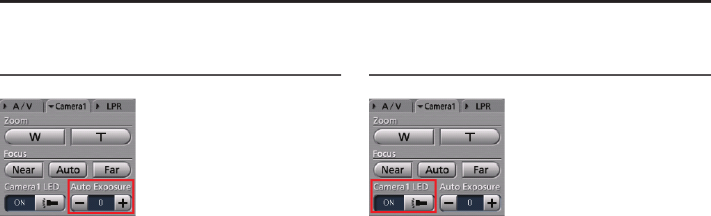
0
1
Operations (continued)
Adjusting image brightness in
record mode
The brightness can be adjusted with the [Auto
Exposure] button on the Camera1 tab.
Normally, leave it set to "0."
To make an image brighter
Click on [+].
To make an image darker
Click on [-].
Turning off the [REC] lamp of the
color camera during recording
The [REC] lamp on the color camera will be lit during
recording. You can make this lamp unlit at any time.
Click on the [Camera1 LED] button on the Camera1
tab to set it to "OFF." This makes the REC lamp always
unlit.
To enable lighting of the REC LED, click on the
Camera1 LED button to set it to "ON."
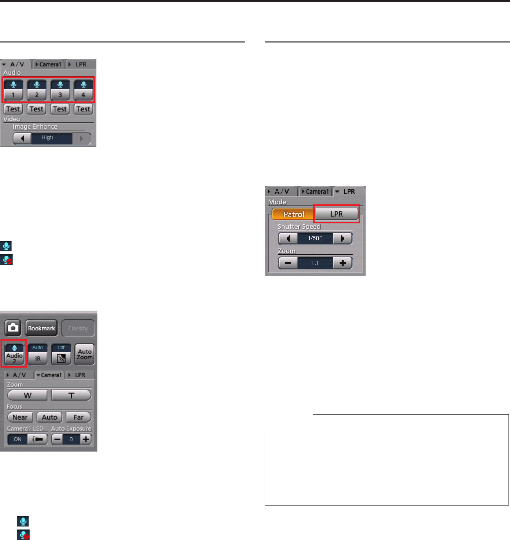
Operations (continued)
Turning audio recording On or Off
Recording of each audio channel can be turned on or
off with the [1], [2], [3], and [4] buttons on the A/V tab.
Click on an audio channel button you wish to set.
The setting is displayed on the upper part of the button.
: The audio channel signal is recorded.
: The audio channel signal is not recorded.
Turning recording of the audio channel 2
On or Off
Click on [Audio 2].
Each time the button is clicked, recording of the audio
channel 2 is turned On or Off. The current setting is
indicated on the upper part of the button.
: The audio channel 2 signal is recorded.
: The audio channel 2 signal is not recorded.
LPR setting
The LPR tab is displayed when Init LPR Mode is set
to ENABLE on the Camera1 screen in Administrator
Setup.
The shutter speed and zoom can be set on the LPR
tab.
(See "Init Camera1 Settings after power ON," page 84.)
Setting the shutter speed
Set a shutter speed to capture sharp video of fast-
moving subjects.
1. Click on [LPR] or [Patrol].
2. Set the shutter speed using Shutter Speed
[◄] or [►].
Setting values in Patrol mode: Auto, 1/100,
1/500, 1/1000
Setting values in LPR mode: Auto, 1/500, 1/1000
The set value is displayed at the center display.
Set the shutter speed, according to the subject.
Note
If recording is started by a recording trigger signal during
License Plate Recognition mode, the shutter speed will
automatically set to Auto. If recording stop conditions are
met, the shutter speed will automatically return to the
value set in Step 2 above.
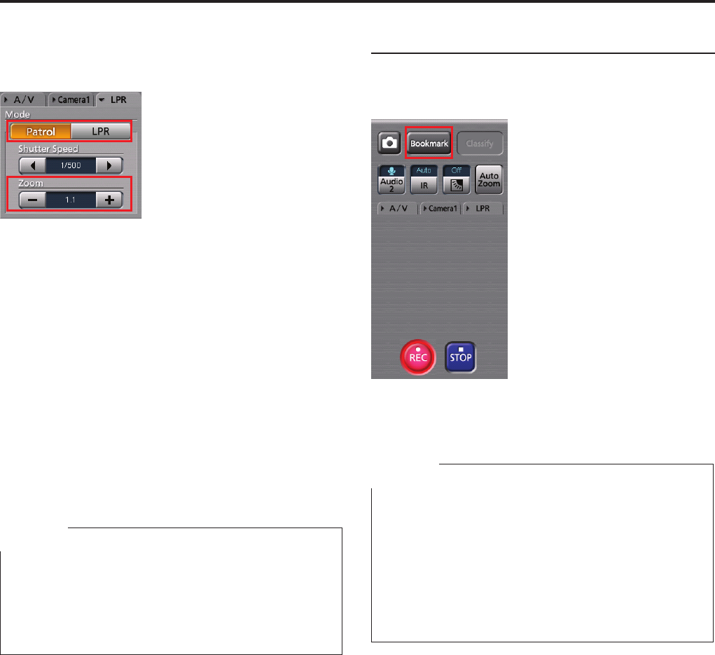
Operations (continued)
Setting the zoom
The zoom magnication of the camera can be set in
the range of ×1.0 to ×22.0.
1. Click on [LPR] or [Patrol].
2. Click on [-] or [+] to set the zoom value.
Clicking on [+] increases the magnication, and
[-] decreases it. The magnitude of increasing/
decreasing amount varies depending on the zoom
magnication.
The zoom range x1.0 to x3.0: increases/
decreases by x0.1
The zoom range x3.0 to x5.0: increases/
decreases by x0.2
The zoom range x5.0 to x10.0: increases/
decreases by x0.5
The zoom range x10.0 to x22.0: increases/
decreases by x1.0
The set value is displayed at the center display.
Note
If recording is started by a recording trigger signal during
License Plate Recognition mode, the zoom setting will
automatically set to [Patrol]. If recording stop conditions
are met, the zoom setting will automatically return to
[LPR].
Adding bookmarks in record mode
A bookmark can be added to a le that is being
recorded to mark it for playback.
Click on [Bookmark].
A bookmark is added and stored.
Notes
Bookmarks can be added with a minimum interval of 2
seconds.
A bookmark cannot be entered until about 2 seconds
after recording starts.
It is possible to move the playback location to a
bookmark position during playback.
Bookmarks can also be added during playback.
(See "Adding bookmarks in archive mode," page 69.)
•
•
•
•
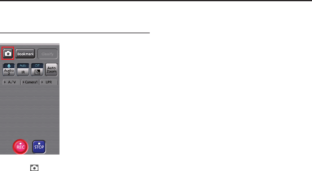
Operations (continued)
Creating a snapshot picture in
record mode
Click on [ ].
A snapshot picture at the current time will be stored in
the preset location.
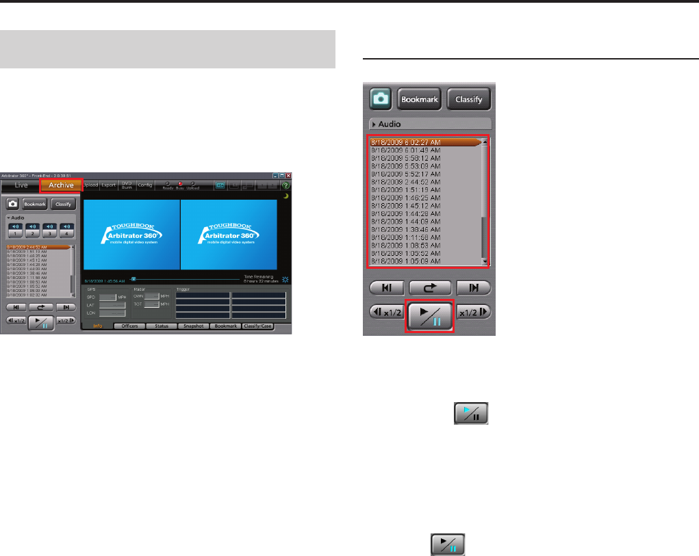
Operations (continued)
Playback in Archive Mode
The video signals recorded in the Memory Card Video
Recorder can be played back in Archive mode. Click
on [Archive] on the toolbar. The Main screen in Archive
mode is displayed.
Playback
1. Select a le you wish to play back from the
le list.
2. Click on [ ] button.
Playback of the selected le starts.
You can also start playback by double-clicking on a le
you wish to play back.
To pause playback
Click on [ ].
Playback pauses.
Playback restarts if you click on the button again.
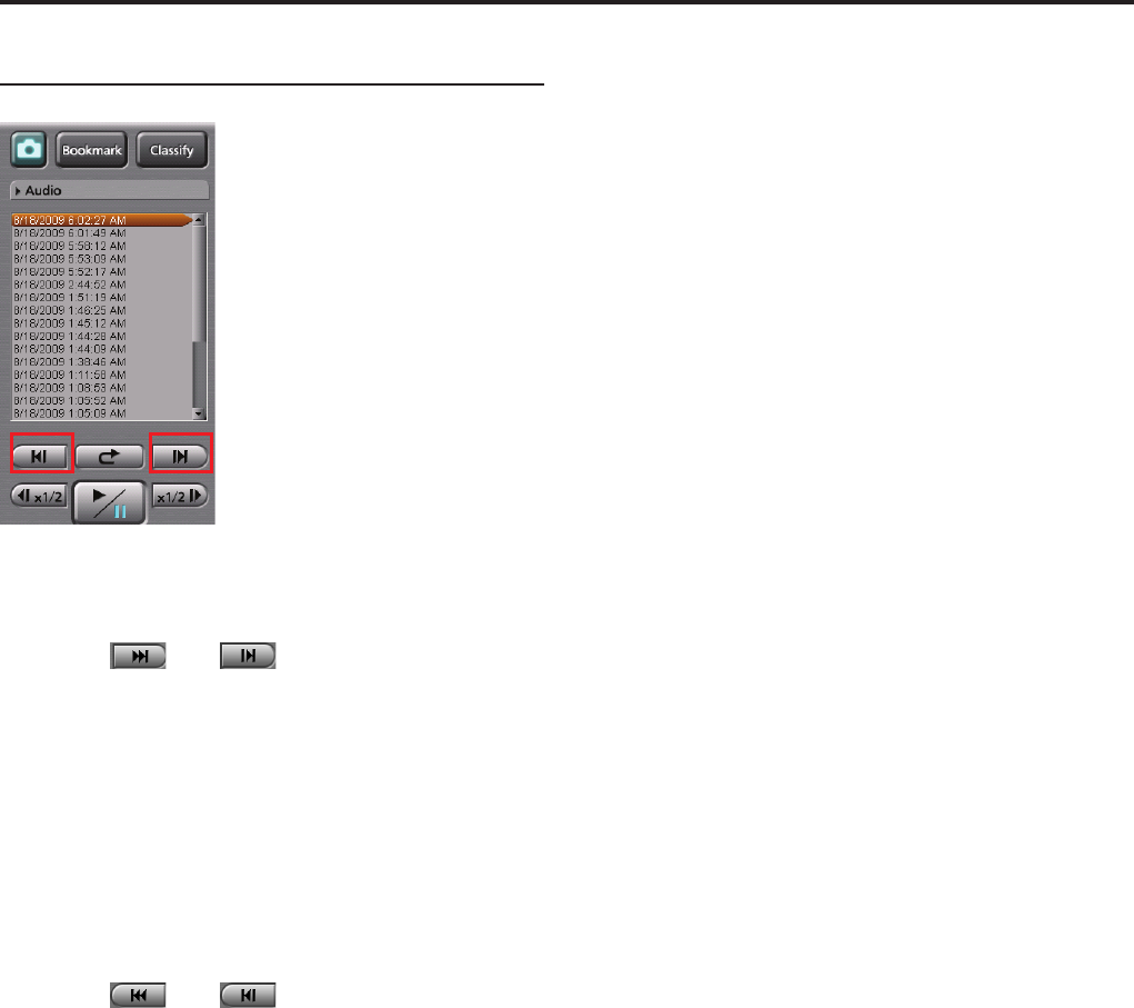
Operations (continued)
Skip playback
You can skip to various playback locations.
Skip forward/Frame forward playback
Click on [ ] or [ ].
If the button is clicked during playback, fast
forward, or fast rewind
Playback from the beginning of the next le on the le
list will start.
If the button is clicked during pause
An image one frame after the current frame will be
displayed.
Skip back/Frame rewind playback
Click on [ ] or [ ].
If the button is clicked during playback
If the button is clicked within 5 seconds after playback
starts, playback of the le before the currently played
back one will start from the beginning.
If the button is clicked after more than 5 seconds after
playback starts, playback of the current le will start
from the beginning.
If the button is clicked during fast forward or
fast rewind
Playback of the le before the currently played back
one will start from the beginning.
If the button is clicked during pause
An image one frame before the current frame will be
displayed.
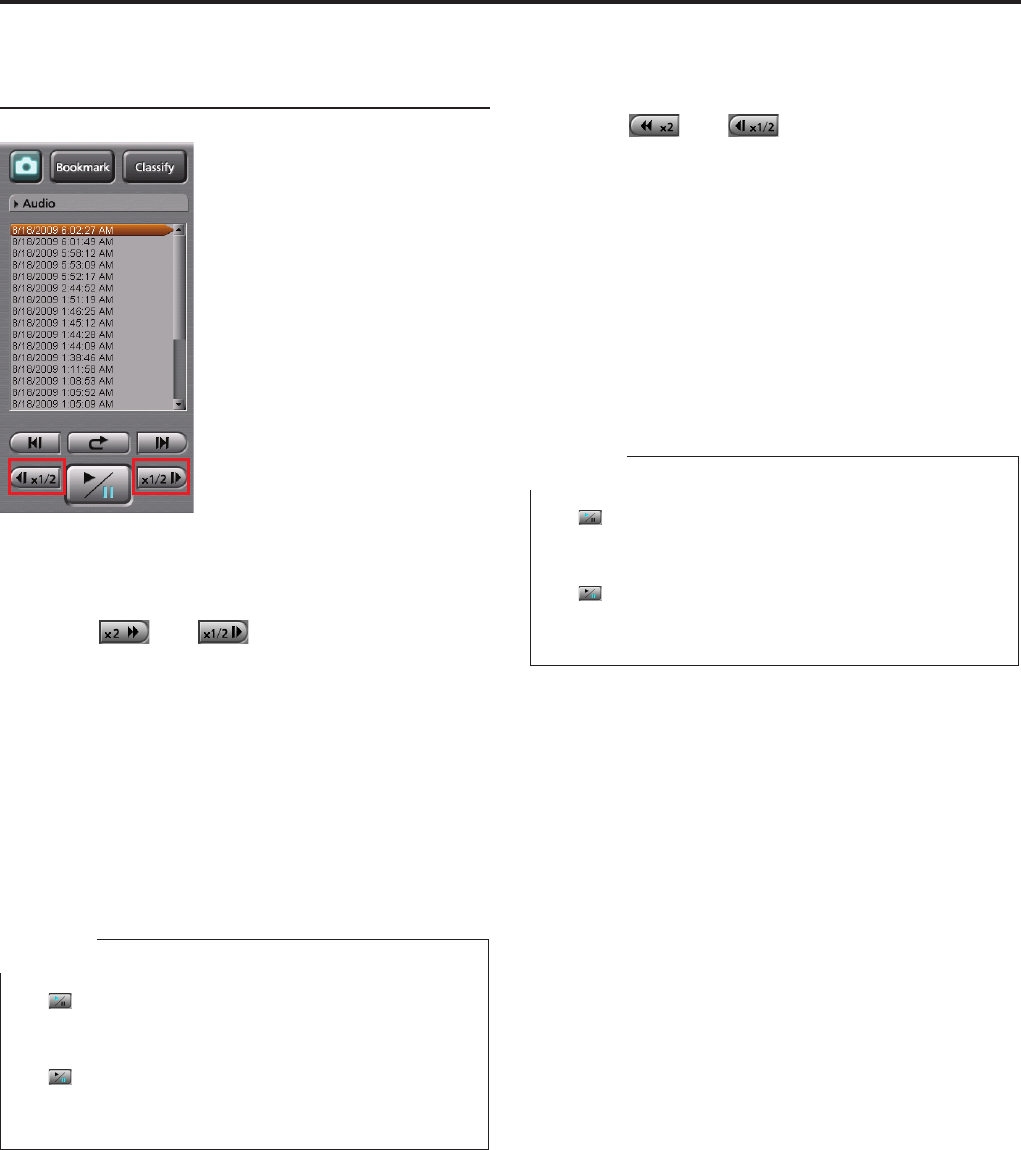
Operations (continued)
Fast rewind, fast forward, and slow
playback
You can change playback speeds.
Fast forward playback and slow playback
Click on [ ] or [ ].
If the button is clicked during playback
Fast forward playback starts. Each time this button is
clicked, fast forward playback speed changes among
x2, x4, and x20.
At the end of the le, playback pauses.
If the button is clicked during pause
Slow playback starts. Each time this button is clicked,
slow playback speed changes between 1/2 and 1/4.
At the end of the le, playback pauses.
Notes
If [ ] is clicked during fast forward, normal playback
starts. The indication for the fast forward button
becomes [x2].
If [ ] is clicked during slow playback, playback
pauses. The indication for the slow playback button
becomes [1/2].
•
•
Fast rewind playback and slow reverse
playback
Click on [ ] or [ ].
If the button is clicked during playback
Fast rewind playback starts. Each time this button is
clicked, fast rewind playback speed changes among
x2, x4, and x20.
At the beginning of the le, playback pauses.
If the button is clicked during pause
Slow reverse playback starts. Each time this button is
clicked, slow reverse playback speed changes between
1/2 and 1/4.
At the beginning of the le, playback pauses.
Notes
If [ ] is clicked during fast rewind, normal playback
starts. The indication for the fast rewind button
becomes [x2].
If [ ] is clicked during slow reverse playback, playback
pauses. The indication for the slow reverse playback
button becomes [1/2].
•
•
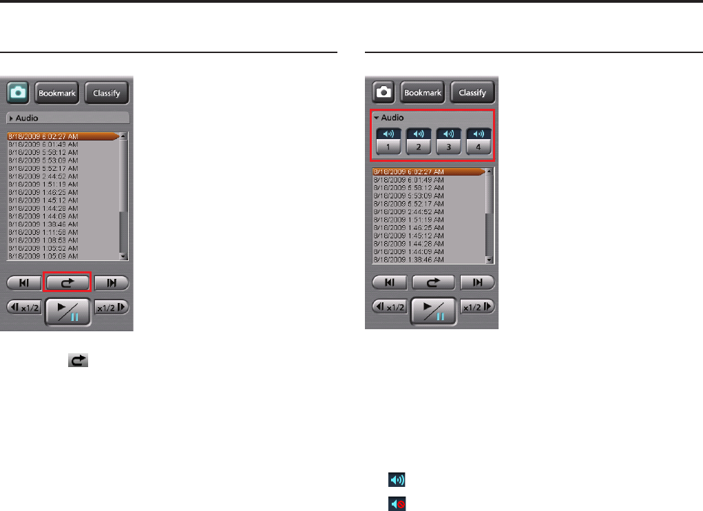
Operations (continued)
Quick replay
Click on [ ].
Playback from a location 7 seconds before the button is
clicked starts. If this button is clicked within 7 seconds
from the beginning of a le, playback starts from the
beginning of the le.
Turning playback sound On or Off
1. Click on the Audio tab to open.
2. Click on an audio channel button you wish
to set.
Each time this button is clicked, On and Off
are switched alternately. The current setting is
displayed on the upper part of the button.
: Playback sound On
: Playback sound Off
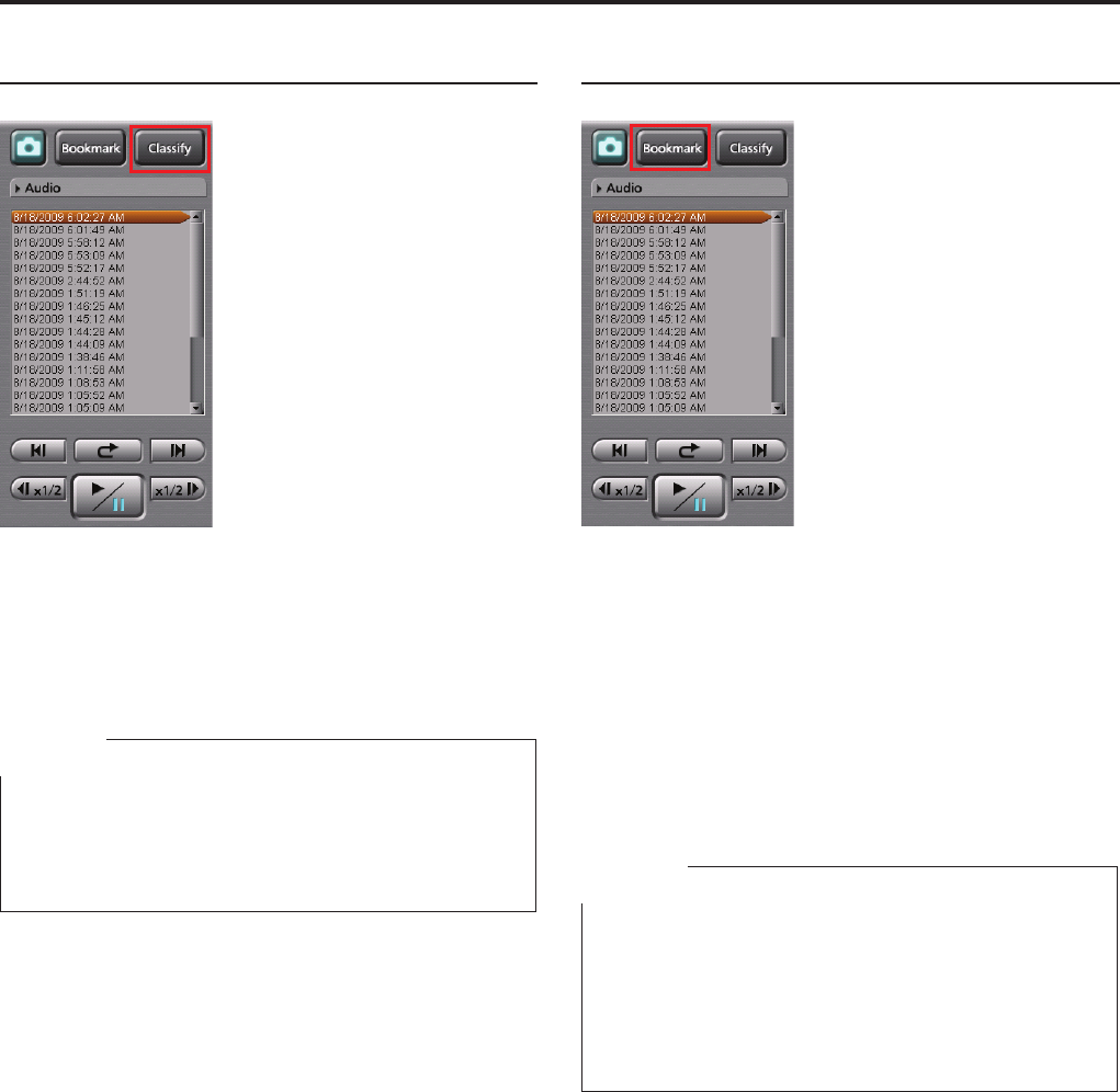
Operations (continued)
Creating classify information
Click on [Classify] during playback.
Playback pauses, and classify information is created.
The Classify tab in the Property section is displayed.
(See "Classify information," page 73.)
Notes
Classify information cannot be created during fast
forward or fast rewind.
The [Classify] button is not available if no classify tag
has been registered.
•
•
Adding bookmarks in archive mode
A bookmark can be added to a le whose playback,
pause, or slow playback is in progress.
Click on [Bookmark] at a location you wish to
add a bookmark.
During pause, a bookmark is added to the currently
paused position.
During playback or slow playback, it pauses. A
bookmark is added to that position, then playback or
slow playback resumes.
Notes
Bookmarks can be added with a minimum interval of 2
seconds.
A bookmark cannot be added during fast forward or fast
rewind.
You can edit bookmarks.
(See "Bookmark information," page 73.)
•
•
•
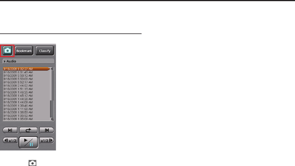
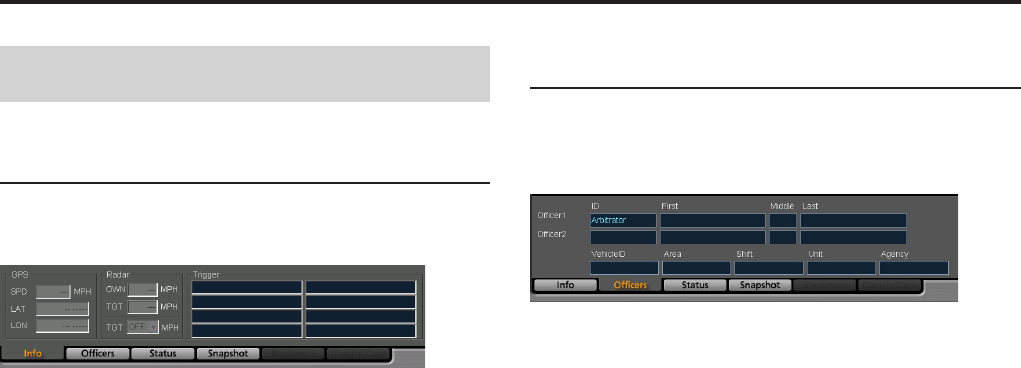
0
1
Operations (continued)
Displaying Information
Meta Information (Info)
If the Info tab is clicked on the Main screen, meta
information will be displayed.
GPS Information
In the GPS information section, the current location
and vehicle speed data obtained from the GPS are
displayed.
SPD: Vehicle speed
LAT: Latitude
LON: Longitude
Radar information
In the Radar information section, the speeds of your
vehicle and target vehicle that are measured by the
radar gun are displayed.
OWN: Speed of your vehicle
TGT: Speed of the target vehicle
TGT (setting): A trigger is output if the speed of the
target vehicle exceeds the set value.
Trigger information
In the Trigger information section, the GPI input status
is displayed.
Ofcer information (
Ofcers
)
If the Ofcers tab is clicked on the Main screen, ofcer
information that is registered in the Memory Card Video
Recorder or written in the meta le will be displayed.
Ofcer information
The ofcer IDs and rst, middle, and last names
for Ofcer 1 and Ofcer 2 are displayed in the
corresponding elds.
Shift information
Data of shiftwork pattern for ofcers are displayed.
Vehicle ID: Vehicle ID
Area: Area
Shift: Shiftwork pattern
Unit: Unit
Agency: Police agency
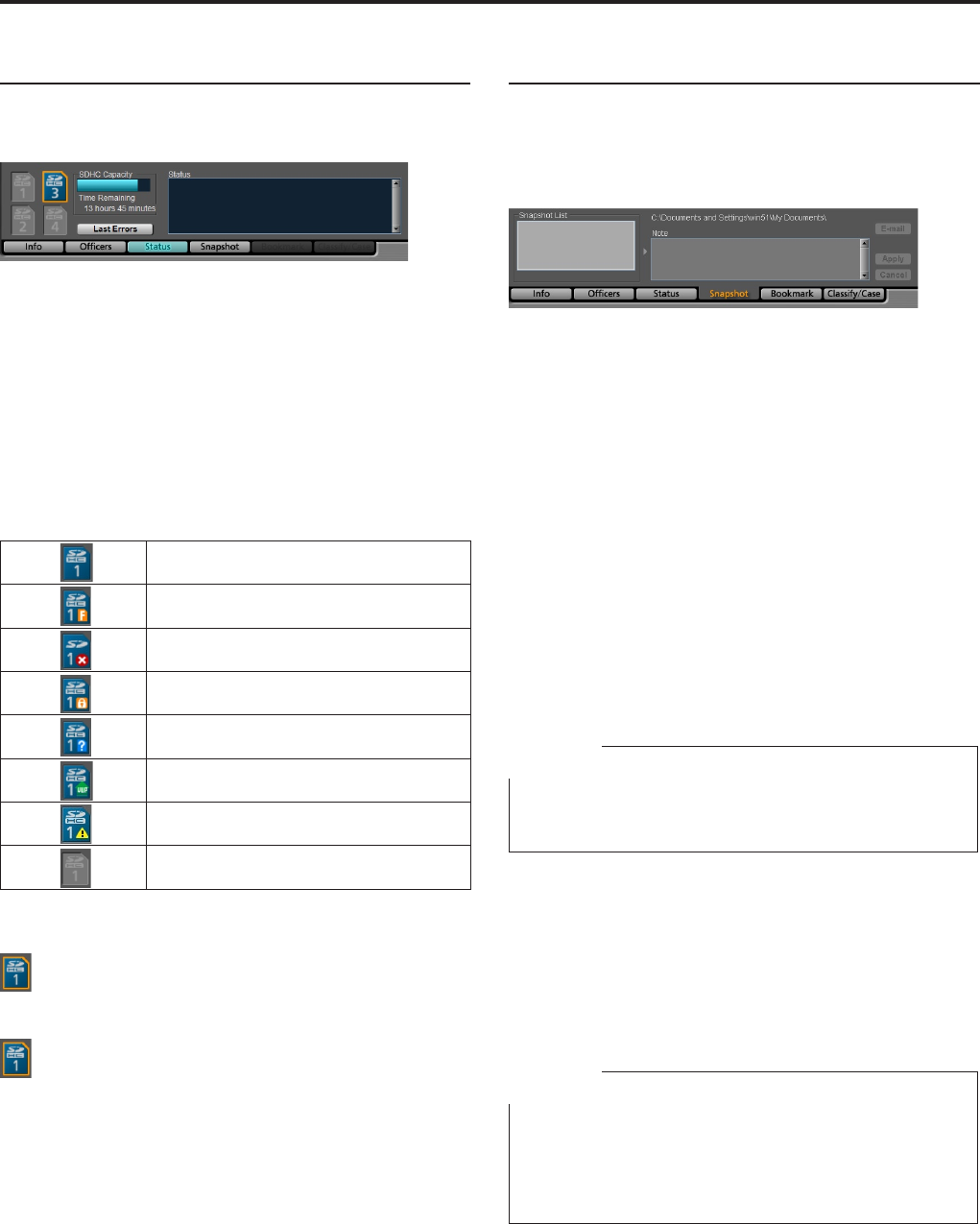
Operations (continued)
Status information (Status)
If the Status tab is clicked on the Main screen, status
information will be displayed.
SDHC Capacity
The remaining duration of the SDHC Memory Cards
loaded in the Memory Card Video Recorder is
displayed. The remaining recordable time with the
current setting will be displayed in "Hour:Minute" in the
Time Remaining eld.
SDHC
The following statuses of the SDHC Memory Card that
is currently used are displayed.
Normal
Full Capacity
Unsupported
Writing prohibited
Unformatted
Update card
Card error
Uninsertion
In Live mode:
The card to be used for next recording is enclosed
with an amber frame.
In Archive mode:
The card that stores video signals being played
back is enclosed with an amber frame.
Status
Data for the video le that is currently displayed are
displayed.
In Live mode:
If an error is generated, its content is displayed.
If the Status tab is not displayed when an error is
generated, a warning mark will be added on the tab.
In Archive mode:
The recording date and time and playback duration of
the selected video le are displayed.
Snapshot information
If the Snapshot tab is clicked on the Main screen,
snapshot information of the selected video le will
be displayed. You can display and edit an assigned
snapshot.
To display a snapshot picture
Select a snapshot you wish to display from the
Snapshot List. The selected snapshot is displayed in
the Video Display Section in Pause mode.
Editing a note
You can edit the note for a snapshot during pause at a
snapshot position.
1. Edit the note in the Note eld.
2. Click on [Apply].
The note for the selected snapshot will be updated.
Canceling editing
Click on [Cancel] before clicking on [Apply].
Note
If no note is edited, the [Apply] and [Cancel] buttons are
not available.
Attaching a snapshot to e-mail
1. Select an image le you wish to attach to
e-mail from the Snapshot List.
2. Click on [E-Mail].
The mailer starts.
Notes
The [E-Mail] button is disabled if no snapshot is
selected.
The latest snapshot will be attached to e-mail during
Live mode.
•
•
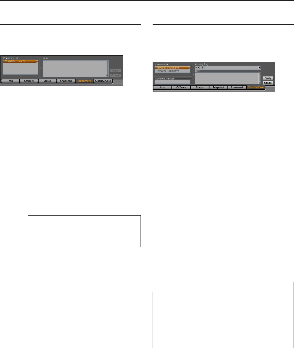
Operations (continued)
Bookmark information
If the Bookmark tab is clicked on the Main screen,
bookmark information will be displayed. It is possible to
move to a desired bookmark position or edit a note.
To move to a desired bookmark position
Select a bookmark from the Bookmark List. The unit
moves to the selected bookmark position then pauses.
Editing a note
You can edit the note for a bookmark during pause at a
bookmark position.
1. Edit the note in the Note eld.
2. Click on [Apply].
The note will be updated with the edited
information.
Canceling editing
Click on [Cancel] before clicking on [Apply].
Note
If no note is edited, the [Apply] and [Cancel] buttons are
not available.
Classify information (Classify/Case)
If the Classify tab is clicked on the Main screen, classify
information will be displayed. It is possible to move to a
desired classify information item position or edit classify
information or a note.
To move to a desired classify information
item position
Select a classify information item from the Classify List.
The unit moves to the selected classify information item
position then pauses.
Editing classify information
You can edit the classify information displayed in the
Classify tag during pause at a classify information
position.
1. Enter a case le number in the Case File
Number eld.
2. Select a classify tag from the dropdown
list.
3. Edit the note in the Note eld.
4. Click on [Apply].
The classify information will be updated with the
edited information.
Canceling editing
Click on [Cancel] before clicking on [Apply].
Notes
If none of Case File Number, Classify Tag, or note
is edited, the [Apply] and [Cancel] buttons are not
available.
A new case le number is created in the database when
a video le is uploaded to the Back-End server. If the
same case le number already exists in the database,
that case le will be associated with the video le.
•
•
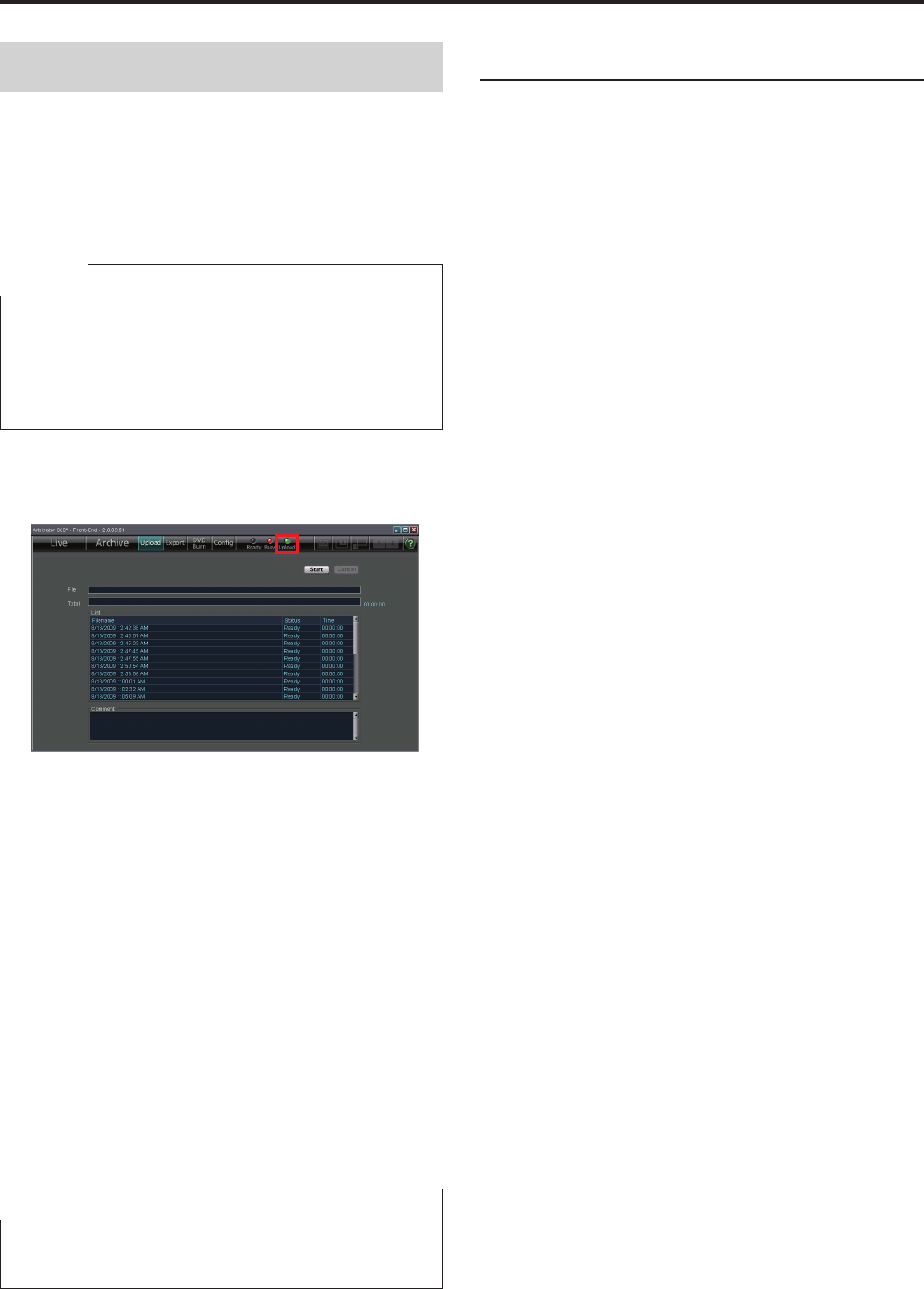
Operations (continued)
Uploading Files
Video data recorded in the Memory Card Video
Recorder can be uploaded to the Back-End server. The
meta-information and bookmark information attached to
the video are also uploaded. Uploaded data are erased
from the Memory Card Video Recorder. Automatic
uploading of video les is also possible.
Note
The videos stored on the Memory Card Video Recorder
can be directly uploaded to the Back-End server by
connecting the Back-End server and the Recorder
directly. If uploading competes with that via the Front-
End Application, direct uploading takes priority.
1. Click on [Upload] on the toolbar.
The Upload screen is displayed.
2. Click on [Start].
Uploading starts. The progress is displayed on the
File bar and Total bar.
The [Upload] lamp on the toolbar will be lit during
uploading.
When uploading is completed, “It nished uploading
the le.” is displayed in the Comment eld.
To cancel uploading
Click on [Cancel].
If an error is generated
The corresponding lename and one of the following
error messages will be displayed in the Comment eld.
Take necessary measures.
•
Communication with the Recorder failed.
•
No free space on the PC
Note
If “Communication with the Recorder failed.” appears,
set the correct IP address on the File Transfer screen.
Automatic uploading
Place a check mark in the "Auto Upload is Enabled"
box on the File Transfer screen in Administrator Setup.
When a UDP packet from the Back-End server is
received, automatic uploading starts.
(
See "Upload," page 87.
)

Operations (continued)
Exporting Files
Video data recorded in the Memory Card Video
Recorder can be exported to the hard disk of a PC or
removable media. As the video data are recorded in
special format, they can only be played back in the
dedicated player application. The dedicated player
application can be exported together with video data.
You can set in Administrator Setup so that exported
video data are automatically deleted from the Memory
Card Video Recorder.
(
See "Export/DVD Burn," page 87.
)
1. Click on [Export] on the toolbar.
The Export screen is displayed.
2. To export the dedicated player application
together, place a check mark in the [With
AV Viewer] box.
3. Click on [Start].
The folder selection dialog box appears.
4. Select an empty folder or make a new
folder, and click on [OK].
Exporting starts. The progress is displayed on the
File bar and Total bar.
If the Password input screen is displayed
The Password input screen is displayed when the [Start]
button is clicked in Step 3 if the current user is not the
administrator and deletion of video data after export is
set. Enter the password then click on [OK]. Exporting
starts.
To cancel exporting
Click on [Cancel].
If an error is generated
The corresponding lename and one of the following
error messages will be displayed in the Comment eld.
•
Communication with the Recorder failed.
•
No le found
•
No free space on the PC
Take necessary measures.
Exporting from the Front-End Application is not
available at present. Upgrading is scheduled for
the future.
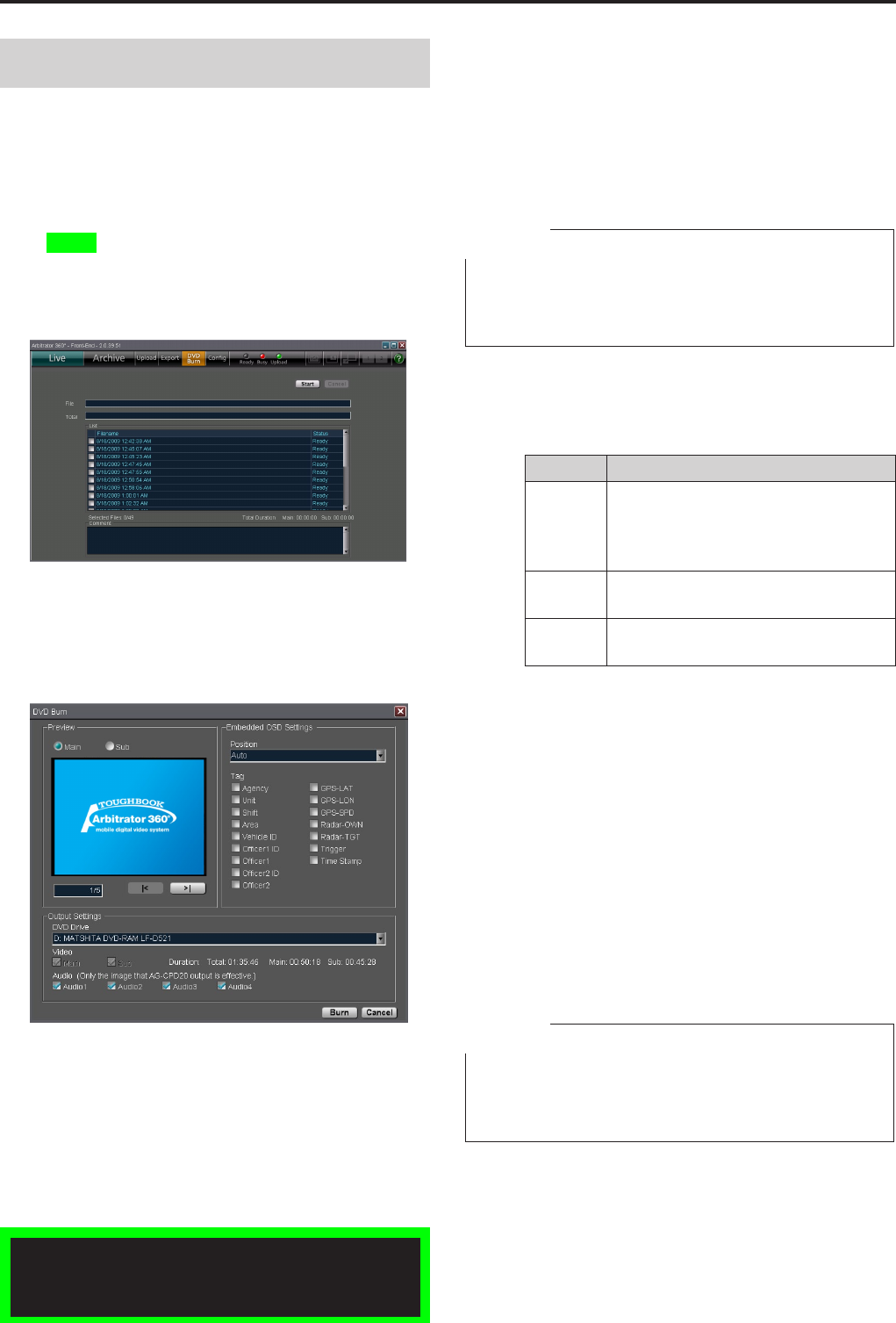
Operations (continued)
Creating a DVD
Video data recorded in the Memory Card Video
Recorder can be output in DVD-Video format for
recording on a DVD.
You can set in Administrator Setup so that output video
data are automatically deleted from the Memory Card
Video Recorder.
(See "Export/DVD Burn," page 87.)
1. Click on [DVD Burn] on the toolbar.
The DVD Burn screen is displayed.
2. Place a check mark in the box for the le(s)
to be output in the List.
3. Click on [Start].
The Embedded OSD setting screen is displayed.
If the Password input screen is displayed
The Password input screen is displayed when the
[Start] button is clicked in Step 3 if the current user
is not the administrator and deletion of video data
after output is set. Enter the password then click on
[OK]. Creation of a DVD starts.
4. Preview the video to be exported on the
Preview screen.
A video le to be previewed can be selected by
clicking on the [|<] or [>|] button. The top of the
Main or Sub video is displayed. The tag specied
by the Embedded OSD Setting is displayed as an
OSD.
Note
The brightness of the preview video on the Embedded
OSD setting screen is xed independent of the Day/Night
View setting on the Day/Time screen.
5. Perform the Embedded OSD, video output
and audio output settings.
Position
Select the display position.
Item Description
Auto The Embedded OSD is displayed so
that it does not overlap the position of
the Embedded OSD setting of the Meta
le. Default setting.
Upper left The Embedded OSD is displayed on the
upper left.
Lower left The Embedded OSD is displayed on the
lower left.
Tag
Select the tags to be set as an Embedded
OSD.
DVD Drive
Set the directory path of the DVD drive.
Video
Select the video to be output. Either the main or
sub video can be selected.
Main: Main video
Sub: Sub video
Duration: Total playback time of the selected
video les
Audio
Select audio channels.
Notes
A maximum of 13 tags can be set.
If a Time Stamp has been embedded in the video, the
Time Stamp of Tag cannot be embedded in the OSD.
•
•
Exporting from the Front-End Application is not
available at present. Upgrading is scheduled for
the future.
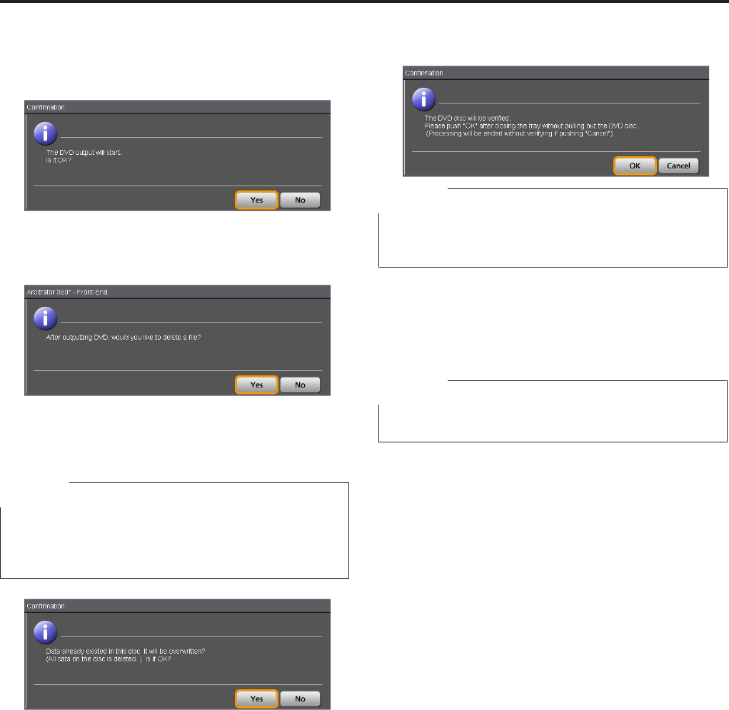
Operations (continued)
6. Click on [Burn].
The Embedded OSD setting screen is closed, and
the conrmation dialog box is displayed.
Click on [Yes] to start DVD output.
The progress is displayed on the File bar and Total
bar.
If conrming of data deletion has been set, the
conrmation dialog box is displayed.
Click on [Yes] to output.
Note
If the le to be output includes main and sub videos and
either of them is set to be copied to a DVD, both the
main and sub videos are deleted upon DVD burn.
If videos are to be output to a rewritable disc, the
conrmation dialog box is displayed.
Click on [Yes] to overwrite. Copying to a DVD
starts.
To cancel copying, click on [No].
7. To verify the DVD disc, click on [OK].
Note
A disc may be ejected on some DVD drive. Reinsert the
disc manually, and verify the disc.
To cancel outputting
Click on [Cancel].
While creating an image, output can be canceled.
Note
When writing to a DVD starts, output cannot be canceled.
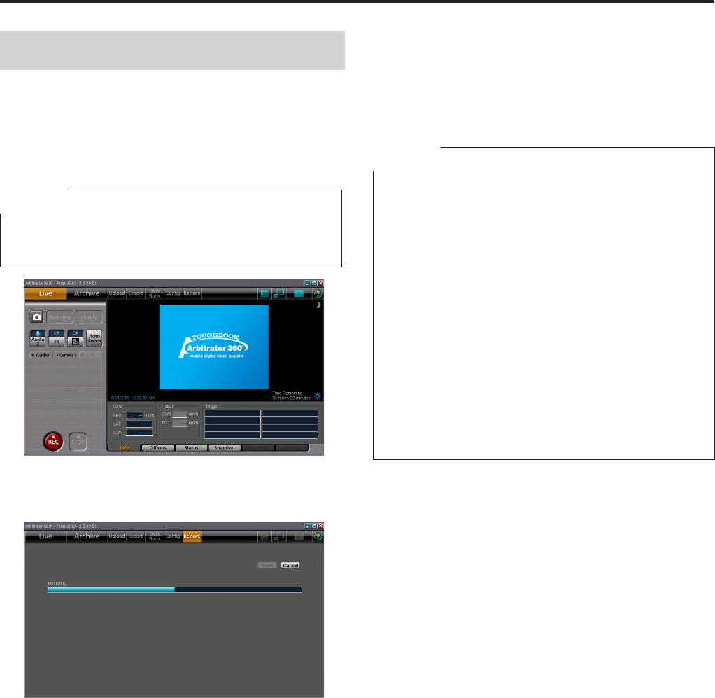
Operations (continued)
Restoring a File
If the power for the Memory Card Video Recorder is
turned off or a P2 card is removed during recording, the
le on the card will be corrupted and cannot be played
back. To play the corrupted le, a restoration operation
is required.
Note
This function is available when the AG-CPG15P or AG-
CPD10CRUP is connected.
1. Click on [Restore] on the toolbar.
The screen shown below appears.
2. Click on [Start].
Restore process begins.
Interrupt restoring
Click on [Cancel].
Restore process is interrupted, and the live screen
appears.
Notes
An interrupted restoration process can be resumed at a
later time.
Recording is still available even if there are les in need
of restoration.
A recording trigger detected during a restoration
process or pressing the [REC] button will interrupt the
process and start recording.
Files that must be restored do not appear on the
playback le list screen. Make sure to restoration the
les beforehand.
Since a seriously corrupted le may not be possible to
restore, do not turn off the unit during P2 card access
(for example, during recording) and do not remove a P2
card when the [BUSY] lamp is lit or blinking.
The live screen reappears once the le restoration
operation completes.
•
•
•
•
•
•
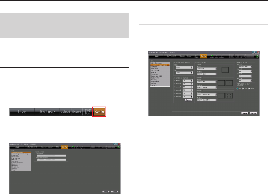
Administrator Setup
Basic Operations for the
Administrator Setup Screen
Opening the Administrator Setup
screen
1. Click on [Cong] on the toolbar of the Main
screen.
The Administrator Password input screen is
displayed.
2. Enter the password in the Password input
box.
3. Reenter the password in the Retype
Password box.
4. Click on the item you wish to set up from
the Item list on the left.
The setting screen for the selected item will be
displayed.
Setting of items
1. Perform the necessary settings and
selections on the displayed setting screen.
2. Click on [Apply].
The changed settings will become valid.
Canceling changes
Click on [Cancel] before clicking on [Apply].
The changes made are canceled, and the settings
before making changes are restored.
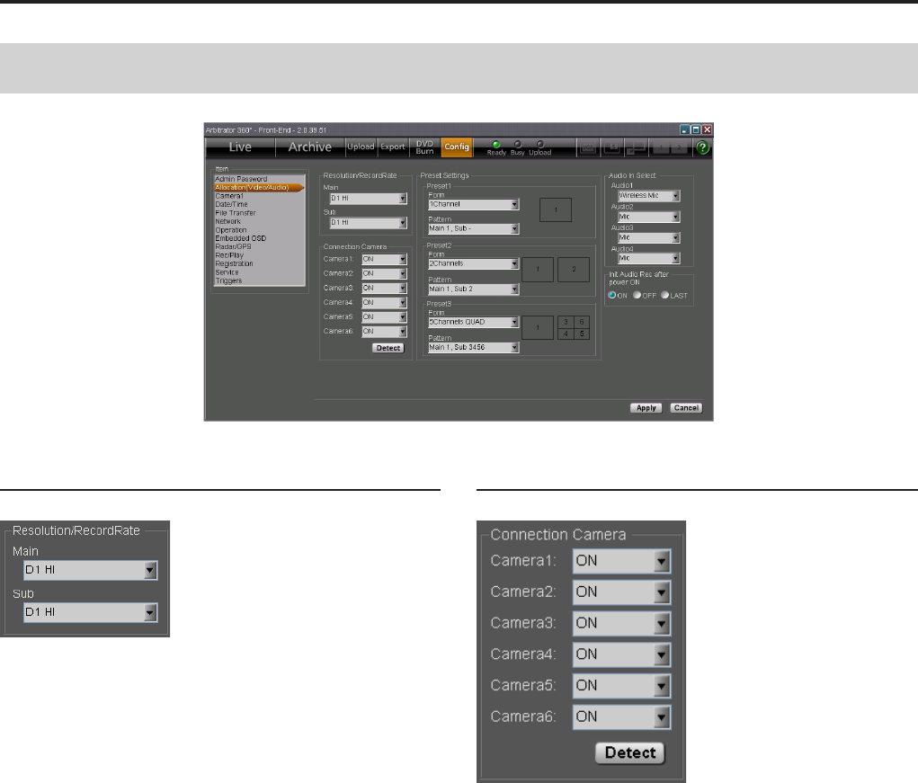
0
Administrator Setup (continued)
1
Allocation (Video/Audio)
Resolution/RecordRate
Select the resolution of the screen and the recording
rate.
Select an appropriate option for the Main screen from
the dropdown list for Main and one for the Sub screen
from that for Sub.
The options are as shown below:
Setting values: D1 HI, D1 STD, D1 10, CIF
If either of the Main or Sub Resolution/RecordRec is
set to “D1 10”, the other is also set to “D1 10”
Connection Camera
Set if a camera is connected to each of [CAMERA
1], [2], [3], [4], [5], and [6] connectors on the Memory
Card Video Recorder. If the connection is changed, the
default settings will be applied to the items in Preset
Settings.
ON: Connected
OFF: Not connected
To automatically detect camera connections
Click on [Detect].
The cameras connected to the Memory Card Video
Recorder will be automatically detected. According
to the detected cameras, the default settings will be
applied to the items in Preset Settings.
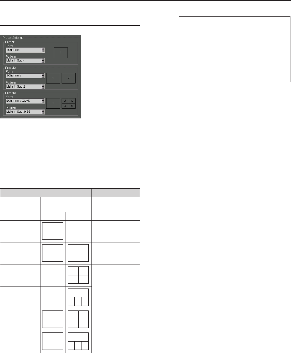
0
1
Administrator Setup (continued)
Preset Settings
The channel mode (Form) and display pattern (Pattern)
of the 6 cameras connected to the Memory Card Video
Recorder can be selected. According to the connection
status of cameras, selectable options are determined.
(See “Camera Connection and Combination of
Cameras” on page 141.)
Three Presets can be set. Presets1-3 that have been
set here can be selected by the Preset switch button on
the toolbar.
Form Pattern
Options
Numbers for cameras
to be displayed
Main Sub
1Channel
1/2/3
- Main 1, Sub-
Main 2, Sub-
Main 3, Sub-
2Channels
1/2
2/3
Main 1, Sub 2
Main 1, Sub 3
Main 2, Sub 3
4Channels-
QUAD
-
1/2/3
4
6
5
Main -, Sub 1456
Main -, Sub 2456
Main -, Sub 3456
4Channels-
PANORAMA
-
1/2/3
4 6 5
5Channels-
QUAD
1/2/3
2/3
4
6
5
Main 1, Sub 2456
Main 1, Sub 3456
Main 2, Sub 3456
Main 3, Sub 2456
5Channels-
PANORAMA
1/2/3
2/3
4 6 5
When [Apply] is clicked, the settings are registered on
the Memory Card Video Recorder.
Note
An error message will be displayed in the cases below.
Settings are overlapped.
Preset3 is valid, but nothing has been set for Preset2.
No camera is connected.
A single camera is connected to [CAMERA 4], [CAMERA
5], or [CAMERA 6] connector on the Memory Card
Video Recorder.
•
•
•
•
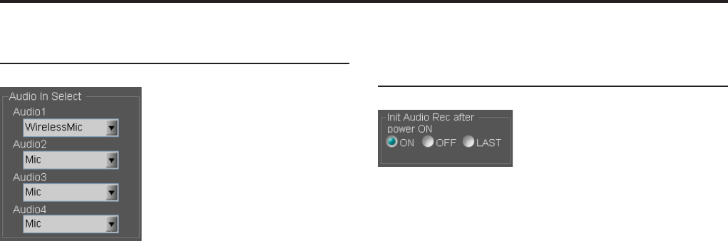
Administrator Setup (continued)
Audio In Select
Select the audio connected to each of [AUDIO IN 1],
[2], [3], and [4] connectors on the Memory Card Video
Recorder.
Mic: Microphone
Wireless Mic: Wireless microphone
Off: No audio input
Init Audio Rec after power ON
(Allocation)
Set the audio recording status upon startup of the
Memory Card Video Recorder. The setting will be
applied to all four audio channels.
ON: Recording
OFF: Not recording
LAST: The setting upon the last power-off will be
restored. If the Memory Card Video Recorder
is not turned off properly, the setting data upon
power-off may not be stored properly.
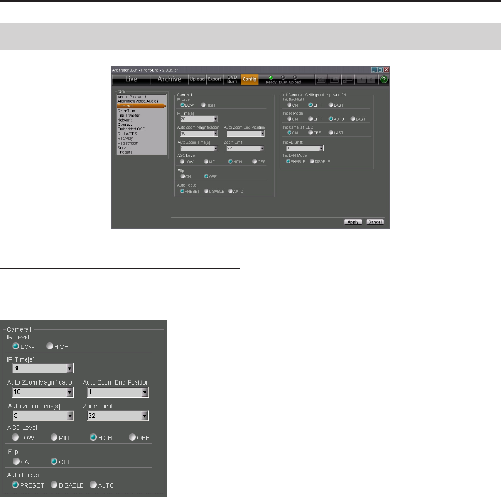
Administrator Setup (continued)
Camera1
Camera1
Perform the settings for the color camera that is
connected to the [CAMERA 1] connector on the
Memory Card Video Recorder.
IR Level
Select the automatic switching level of infrared imaging
when the IR function is set to Auto.
LOW: Low level
HIGH: High level
IR time[s]
Select the time required for detecting the brightness
used for automatic switching to/from infrared imaging,
when the IR function is set to Auto.
Setting values: 10, 30, 60, 300 (seconds)
Auto Zoom Magnication
Set the maximum zoom magnication during automatic
zooming.
Setting values: 1, 2, 3, 4, 5, 7, 10, 15, 22
Auto Zoom Time[s]
Set the keeping time of the maximum zoom
magnication during automatic zooming.
Setting values: 3, 5, 8 (seconds)
Auto Zoom End Position
Set the automatic zooming end magnication position.
Setting values: 1, 2, 3, 4, 5, 7, 10, 15, 22, LAST
Zoom Limit
Set the maximum zoom magnication.
Setting values: 22, 220
AGC Level
Set the gain level for camera input.
LOW: Low
MID: Middle
HIGH: High
OFF: No setting
Flip
Set if vertical ipping of the camera output image will
be performed or not.
ON: Flipped
OFF: Not ipped
Administrator Setup (continued)
Auto Focus
Set the focusing method of the color camera in the
following conditions:
•
When "Init LPR Mode" is set to "DISABLE"
•
When "Init LPR Mode" is set to "ENABLE" and "LPR
Mode" is set to "PATROL"
•
When recording is started by a recording trigger signal
with "Init LPR Mode" set to "ENABLE" and "LPR
Mode" set to "LPR"
PRESET: When the zoom magnication is set to
×3 or less, the camera focuses on an object at
about 15 m distance from the camera. If zooming
operation is performed afterward, automatic
focusing will be activated.
DISABLE: The focal position is xed at a distance
of about 40 m, and automatic focus is disabled.
AUTO: Automatic focus is enabled.
Init Camera1 Settings after power ON
Perform the initial settings for the color camera that
is connected to the [CAMERA 1] connector on the
Memory Card Video Recorder.
Init Backlight
Set if the backlight compensation is On or Off.
ON: The function is enabled.
OFF: The function is disabled.
LAST: The setting upon the last power-off will be
restored. If the Memory Card Video Recorder
is not turned off properly, the setting data upon
power-off may not be stored properly.
Init IR Mode
Set if the IR function is On or Off.
ON: The function is enabled.
OFF: The function is disabled.
AUTO: The function is automatically turned ON or OFF.
LAST: The setting upon the last power-off will be
restored. If the Memory Card Video Recorder
is not turned off properly, the setting data upon
power-off may not be stored properly.
Init Camera1 LED
Set if the [REC] lamp of the color camera is lit or not
during recording.
ON: The lamp lights.
OFF: The lamp does not light.
LAST: The setting upon the last power-off will be
restored when the camera is turned on. If the
Memory Card Video Recorder is not turned off
properly, the setting data upon power-off may not
be stored properly.
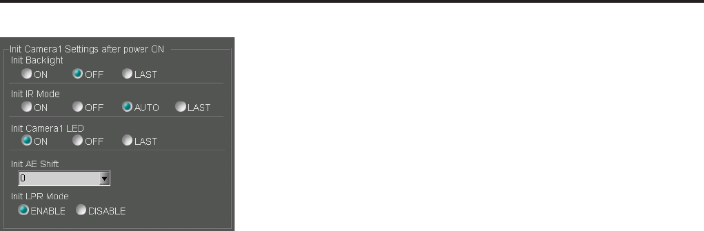
Administrator Setup (continued)
Init AE Shift
Set the brightness of images upon power-on of the
color camera.
Setting values: 2, 1, 0, -1 , -2, LAST (The setting
upon the last power-off will be restored when the
camera is turned on. If the Memory Card Video
Recorder is not turned off properly, the setting
data upon power-off may not be stored properly.)
Init LPR Mode
Set if the LPR (License Plate Recognition) function is
enabled or not.
ENABLE: The LPR function is enabled, and [LPR
Mode] setting change by the user becomes
possible. The setting upon the last power-off is
stored and will be restored upon power-on of the
color camera.
DISABLE: The LPR function is disabled.
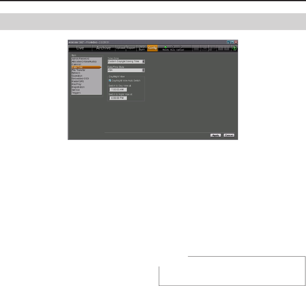
Administrator Setup (continued)
Date/Time
Time Zone
Select the time zone:
Hawaii Standard Time
Yukon Standard Time
Yukon Daylight Saving Time
Pacic Standard Time
Pacic Daylight Saving Time
Mountain Standard Time
Mountain Daylight Saving Time
Central Standard Time
Central Daylight Saving Time
Eastern Standard Time
Eastern Daylight Saving Time
Atlantic Standard Time
Atlantic Daylight Saving Time
Asia Tokyo
Date/Time Style
Set the display pattern of date and time.
ISO: YYYY-MM-DD HH:MM:SS
USA: MM/DD/YYYY HH:MM:SS
Day/Night View
When the Day/Night View Auto Switch check box is
checked, Day and Night modes are automatically
switched.
Mode switching time setting
Set the Day/Night mode switching time when "Day/
Night View Auto Switch" is enabled. "Switch to Day
View at" species the time for shifting to Day mode,
and "Switch to Night View at" species the time for
shifting to Night mode.
Setting range: 00:00:00 AM-11:59:59 PM
Note
Displayed time (12/24-hour system) depends on the
setting of your PC.
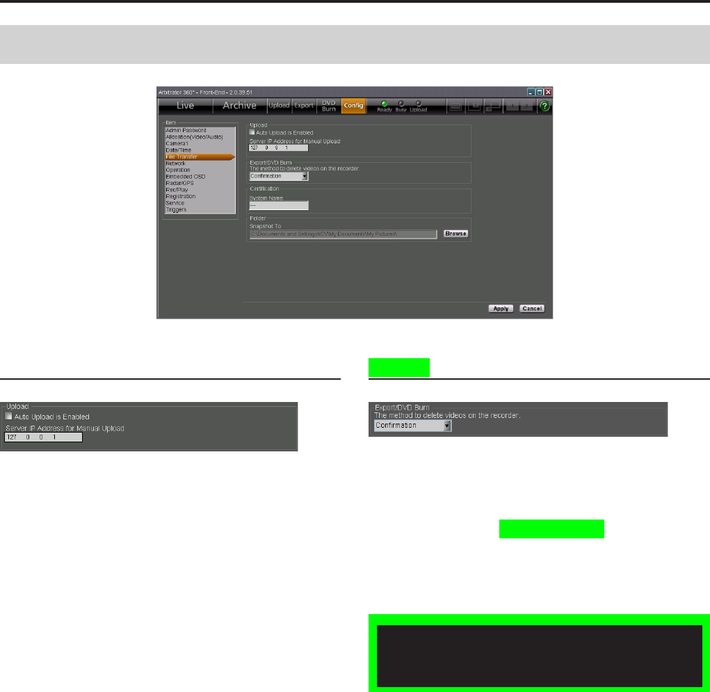
Administrator Setup (continued)
File Transfer
Upload
Auto Upload is Enabled
When a check mark is placed in the box, automatic
uploading is enabled.
Automatic uploading is disabled as default.
Server IP Address for Manual Upload
Set the IP address for the Back-End server that is used
for manual uploading.
Export/DVD Burn
The method to delete videos on the
recorder
Select how to delete video les from the Memory Card
Video Recorder after data exporting or DVD burning.
Force: Automatically deleted
Conrmation: A conrmation screen is displayed.
Files are deleted after reconrmation.
Exporting from the Front-End Application is not
available at present. Upgrading is scheduled for
the future.
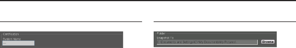
Administrator Setup (continued)
Certication
System Name
Set the system name of the Memory Card Video
Recorder within 50 characters. When the Recorder
directly communicates with the Back-End system, the
communications is enabled only when the name set
here and that registered in the Back-End system are
the same.
Folder
Snapshot To
Set a folder in which snapshot les are to be stored.
The default setting is "My Pictures" for Windows XP
and "Pictures" for Windows Vista.
Use the [Refer] button to assign the folder.
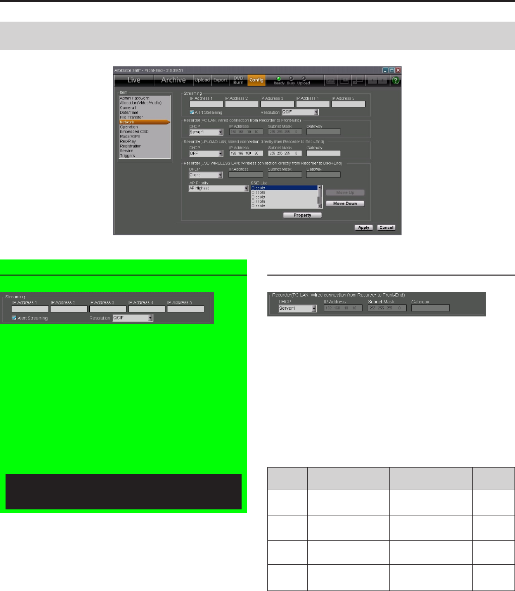
Administrator Setup (continued)
Network
Streaming
Set the IP addresses for the Back-End server. Up to 5
IP addresses can be registered.
The Front-End application periodically sends packets to
these IP addresses. The Back-End server recognizes
the sender of a packet as a streaming target.
Alert streaming
If a check mark is placed in the Alert Streaming
box, when streaming is in progress in the Back-
End application, that is indicated on the Front-End
application screen.
Resolution
Set the resolution of the video in streaming.
Recorder (PC LAN)
Perform the settings for the wired network between
the Memory Card Video Recorder and the Front-End
application.
DHCP
Set if the LAN port on the Memory Card Video
Recorder is to serve as a DHCP server or not.
If DHCP is set to OFF, the port will not serve as a
DHCP server.
If the port is set as a DHCP server, the network settings
are as shown below:
DHCP IP Address Subnet Mask Gateway
DHCP
Server1 192.168.10.10 255.255.255.0 empty
DHCP
Server2 192.168.217.192 255.255.255.0 empty
DHCP
Server3 172.24.217.192 255.255.255.0 empty
DHCP
Server4 10.216.217.192 255.255.255.0 empty
Streaming is not available at present. Upgrading
is scheduled for the future.
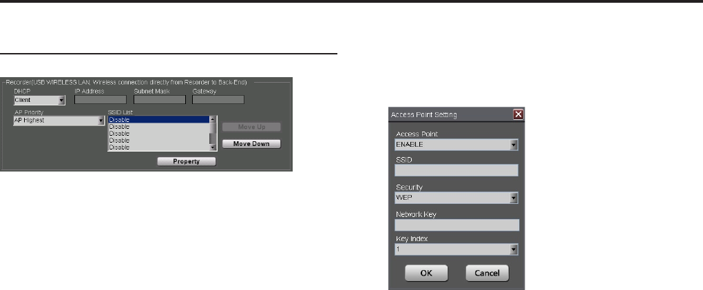
0
Administrator Setup (continued)
1
Recorder (USB WIRELESS LAN)
Perform the settings for the USB wireless LAN port that
is used for connection between the Memory Card Video
Recorder and the Back-End application.
When the LAN port setting is obtained from the
DHCP server: Set DHCP to Client.
When the LAN port setting is not obtained from
the DHCP server: Set DHCP to OFF, and set the
IP Address, Subnet Mask, and Gateway.
To set the connection order priority of
access points
Set AP Priority, as shown below:
Follow the order in the SSID List: A connection is
attempted in the order in the SSID List.
Random: A connection to an access point is
attempted randomly.
To change the order in the SSID List:
1. Select an access point whose priority order
you wish to change in the SSID List.
2. For raising the priority, click on [Move Up].
For lowering the priority, click on [Move
Down].
Adding an access point
1. Click on [Property].
The Access Point Setting screen is displayed.
2. Set Access Point to ENABLE.
If it is set to DISABLE, the access point setting
becomes invalid.
3. Set SSID.
4.
In Security, select the encryption method.
5. If Security is set to either WEP or WPA,
perform a setting for Network Key.
6 If Security is set to WEP, select the Key
Index from among 1, 2, 3, and 4.
7. Click on [OK].
To cancel changes to the setting
Click on [Cancel] before clicking on [OK].
Editing an access point
1. Click on [Property].
The Access Point Setting screen is displayed.
2. Edit items.
3. Click on [OK].
To cancel changes to the items
Click on [Cancel] before clicking on [OK].

0
1
Administrator Setup (continued)
Recorder (UPLOAD LAN)
Perform the settings for the wired LAN port that is
used for connection between the Memory Card Video
Recorder and the Back-End application.
When the LAN port setting is obtained from the
DHCP server: Set DHCP to Client.
When the LAN port setting is not obtained from
the DHCP server: Set DHCP to OFF, and set the
IP Address, Subnet Mask, and Gateway.
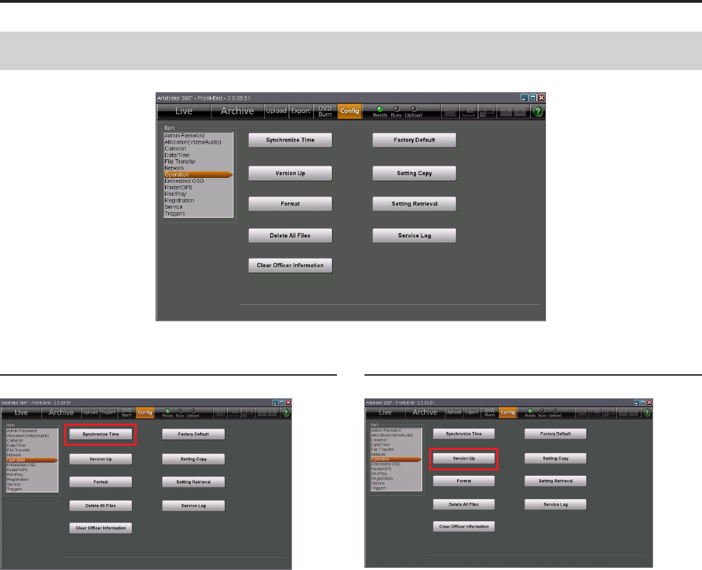
Administrator Setup (continued)
Operation
Synchronize Time
To synchronize the clock of the Memory Card Video
Recorder with that of the PC, click on [Synchronize
Time].
Version Up
Upgrade the rmware of the Memory Card Video
Recorder, as shown in the following steps.
1. Load the rmware of the Memory Card
Video Recorder in the root directory of the
USB memory device.
2. Connect a USB memory device.
In a case of the AG-CPD20P or AG-CPD10CRUP:
Connect a USB memory device to the PC.
In a case of the AG-CPD15P: Connect a USB
memory device to the AG-CPD15P.
3. Click on [Version Up].
A conrmation dialog box is displayed.
4. Click on [YES].
The progress dialog box is displayed, and version
upgrade is performed.
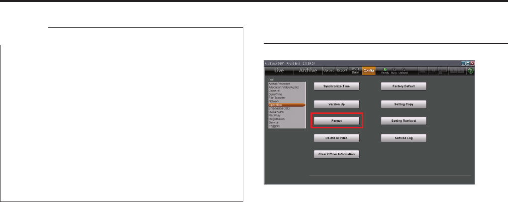
Administrator Setup (continued)
Notes
Do not use any button of the PC and the Memory
Card Video Recorder or turn them off during version
upgrade.
If version upgrade fails, an error message is displayed
and version upgrade is canceled. (See "Error
Messages," page 128.)
When the AG-CPD15P is used, version upgrade cannot
be performed when the following conditions exist in the
root directory:
- If a DATA folder is present
- If multiple version upgrade les (.VUP extension) are
present
•
•
•
To cancel version upgrade
Click on [No].
Format
Use this function to format all SDHC Memory Cards
loaded in the Memory Card Video Recorder.
All video and audio data les that are stored in the
SDHC Memory Cards will be deleted.
1. Click on [Format].
A conrmation dialog box is displayed.
2. Click on [Yes].
Formatting starts.
To cancel formatting
Click on [No].
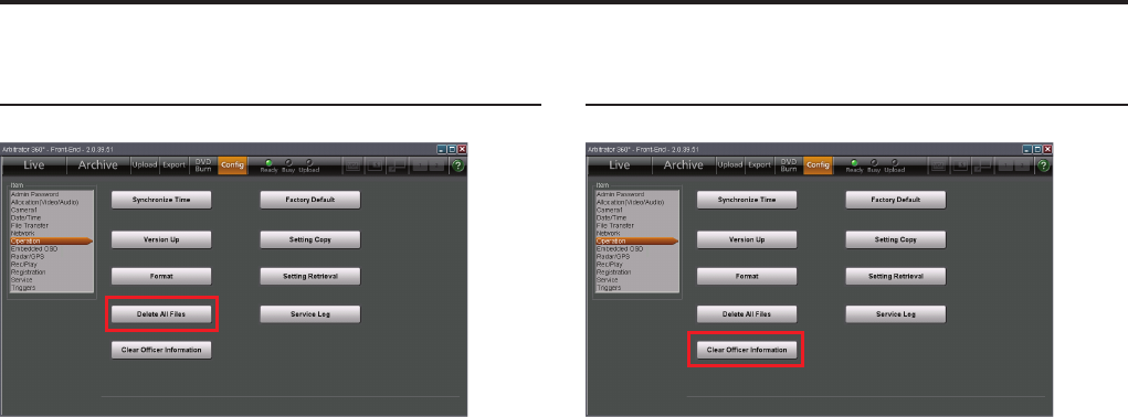
Administrator Setup (continued)
Delete All Files
All video and audio data les that are stored in the
SDHC Memory Cards will be deleted.
1. Click on [Delete All Files].
A conrmation dialog box is displayed.
2. Click on [Yes].
All les are deleted.
To cancel deleting
Click on [No].
Clear Ofcer Information
Use this function to delete the data for Ofcer1,
Ofcer2, VehicleID, Area, Unit, Agency, and Shift
registered in the Memory Card Video Recorder.
1. Click on [Clear Personal Information].
A conrmation dialog box is displayed.
2. Click on [Yes].
Personal information is cleared.
To cancel deleting
Click on [No].
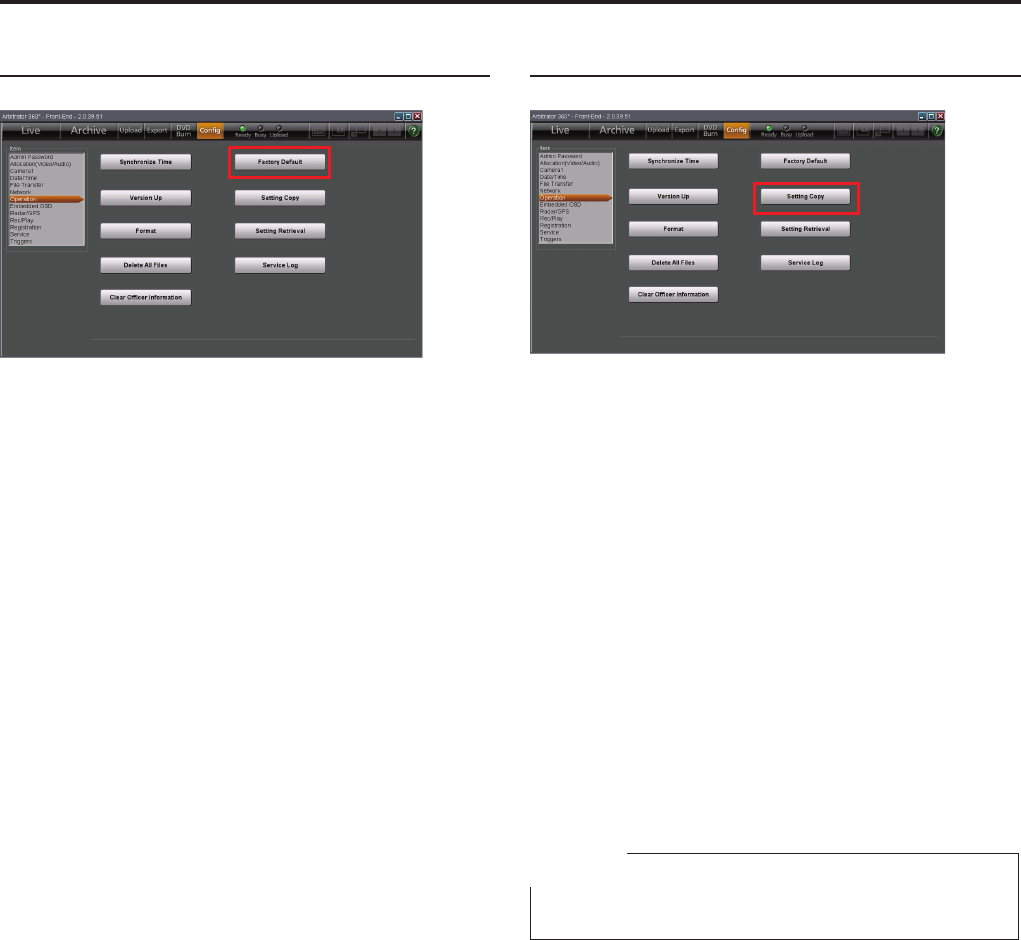
Administrator Setup (continued)
Factory Default
Click on [Factory Default].
All settings of the Memory Card Video Recorder and
Front-End application can be reset to their factory
defaults.
Note that the recorder and application will not revert
to user made settings after being reset to their factory
defaults. Make sure you really want to return all settings
to their factory defaults before performing the following
steps.
Setting Copy
The current setting data of the Memory Card Video
Recorder and the Front-End application can be copied
onto external media, such as a USB memory device.
1. Connect a USB memory device.
In a case of the AG-CPD20P: Connect a USB
memory device to the PC.
In a case of the AG-CPD15P: Connect a USB
memory device to the AG-CPD15P.
2. Click on [Setting Copy].
3. Select the destination folder for copying.
The setting data will be copied onto the selected
folder in the USB memory device.
Upon completion of copying, the dialog box closes.
To cancel copying
Click on [Cancel]. Copying is canceled, and the dialog
box closes.
Note
This function is not available with the AG-CPD10CRUP.
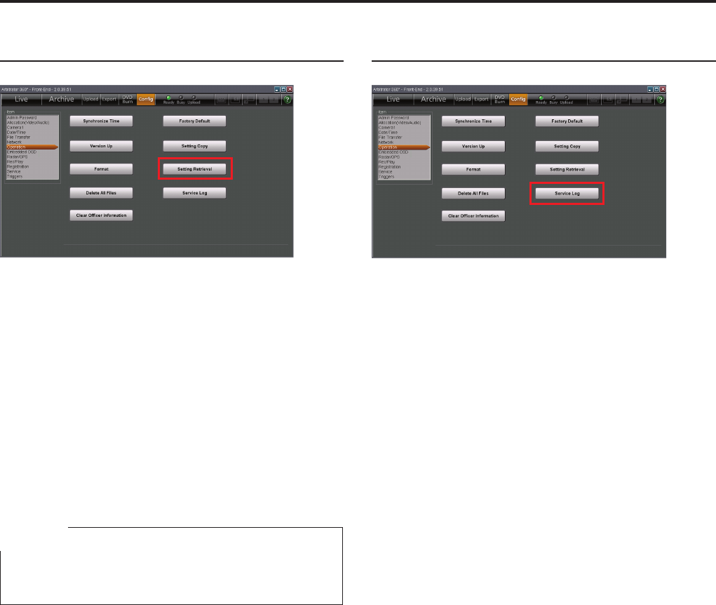
Administrator Setup (continued)
Setting Retrieval
The setting data for the Memory Card Video Recorder
and the Front-End application that have been exported
to a USB memory device with the Setting Copy function
can be copied back.
1. Connect the USB memory device to the PC.
2. Click on [Setting Retrieval].
3. Select a setting le to be copied back.
The setting data are copied from the USB memory
device onto the Memory Card Video Recorder.
Upon completion of setting retrieval, a completion
dialog box is displayed.
Note
This function is not available with the AG-CPD15P and
AG-CPD10CRUP.
Service Log
The operation log of the Memory Card Video Recorder
can be exported to external media.
1. Click on [Service Log].
A le storage dialog box is displayed.
2. Specify the le storage location.
The operation log is exported.
If exporting fails, an error dialog box is displayed.
For details on service log, see "Service Logs", page
142.
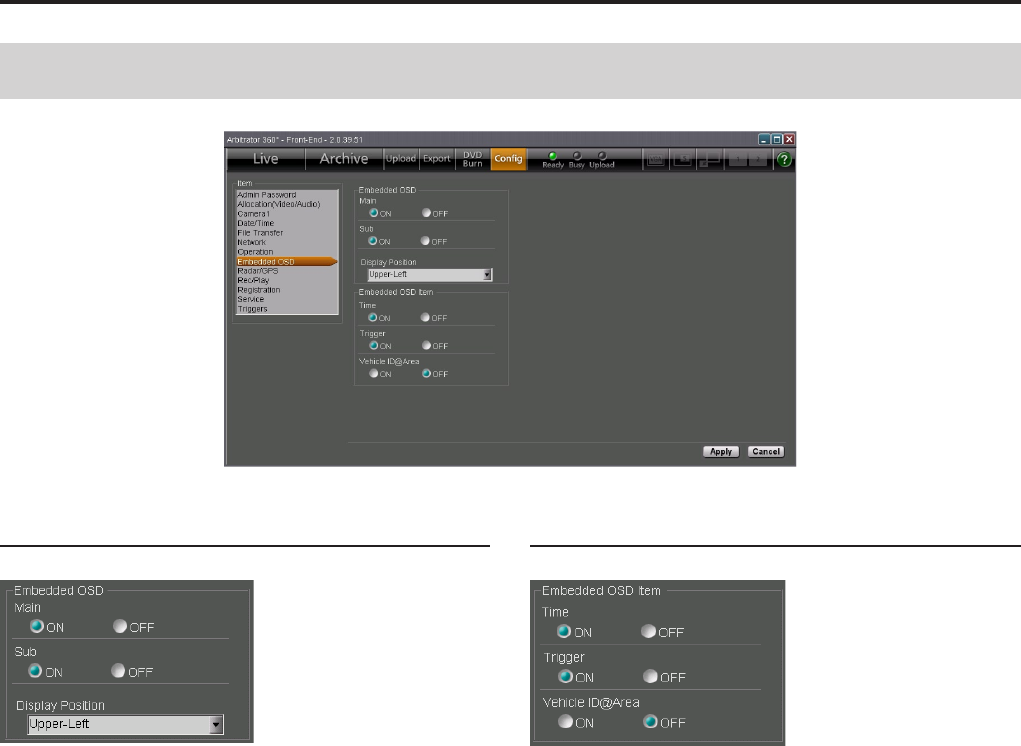
Administrator Setup (continued)
Embedded OSD
Embedded OSD
Main, Sub
Set if Embedded OSD is displayed on the Main screen
(Main) and Sub screen (Sub).
ON: Displayed
OFF: Not displayed
Display Position
Set the Embedded OSD display position on the screen.
Upper-Left: At the upper left
Upper-Right: At the upper right
Bottom-Left: At the bottom left
Bottom-Right: At the bottom right
Embedded OSD Item
Display item setting
Set if Time, Trigger, VehicleID@Area data are displayed
as Embedded OSD or not.
ON: Displayed
OFF: Not displayed
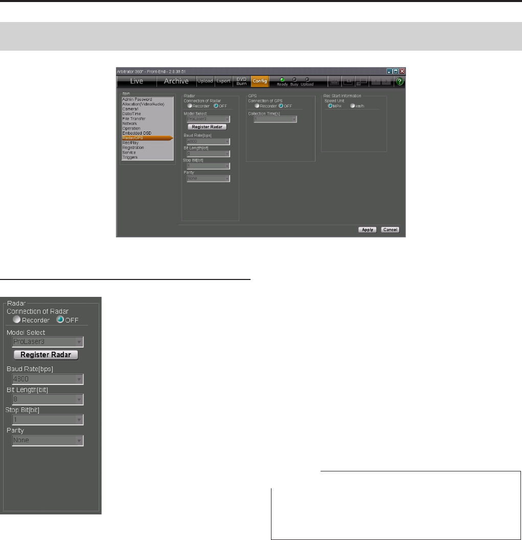
Administrator Setup (continued)
Radar/GPS
Radar
Connection of Radar
Select if a radar gun is connected to the Memory Card
Video Recorder or not.
Recorder: Connected
OFF: Not connected
Model Select
Select the model of the radar gun. The radar gun model
data registered in the Memory Card Video Recorder
are displayed in the dropdown list.
ProLaser3: For Kustom Signals Inc.’s ProLaser3
STALKER_DUAL: For Applied Concepts, Inc.’s
STALKER DUAL.
GOLDEN_EAGLE_II: For Kustom Signals Inc.’s
Golden Eagle II
Registering radar
Load radar gun library data via a USB memory device
then register them to the Memory Card Video Recorder.
1. Copy the radar gun library onto a USB
memory device.
2. Connect the USB memory device to the PC.
3. Click on [Register Radar].
4. Select the folder to be copied.
The radar gun library data are copied from the
USB memory device onto the Memory Card Video
Recorder then registered.
Upon completion of registration, a completion
dialog box is displayed.
Note
An error dialog box will be displayed when no effective le
is found on the USB memory device or registration was
failed.

Administrator Setup (continued)
Specifications for serial communication
The specications for the serial communication are
displayed when a radar gun is connected.
Baud Rate[bps]
Bit Length[bit]
Stop Bit[bit]
Parity
Notes
Some radar guns come with a function for setting
conditions that enable correct measurement of target
vehicle speed. Use this function according to the
instructions in the Operating Instructions of the radar gun.
Error messages appear when the radar gun is
operating abnormally.
•
•
GPS
Connection of GPS
Select if the GPS is connected to the Memory Card
Video Recorder or not.
Recorder: Connected
OFF: Not connected
Collection Time[s]
Select an interval of collecting data from the GPS.
Setting values: 1, 2, 5, 10 (seconds)

100
Administrator Setup (continued)
101
Rec Start Information
Speed Unit
Select the speed unit (MPH or km/h) to be used in a
case where recording is started with the vehicle speed
of your vehicle that is obtained from the GPS or the
radar gun. The selected unit is displayed on the Info
tab.
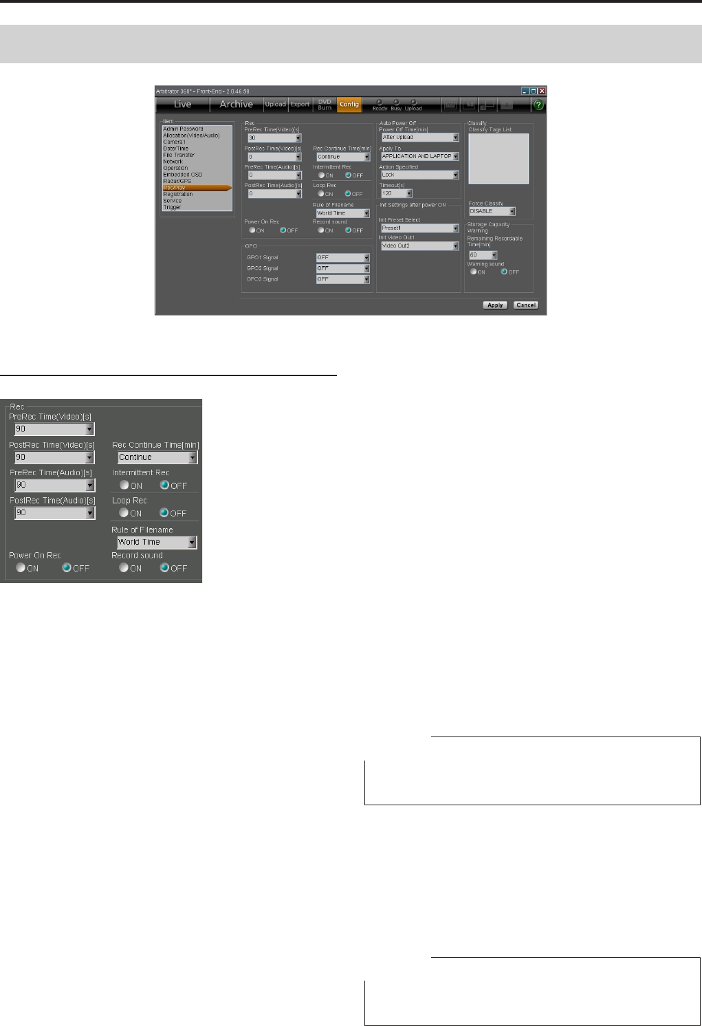
100
101
Administrator Setup (continued)
Rec
PreRec Time
Use this function to set how much of already stored
video/audio will be retained when a trigger is entered or
the [REC] button is pressed.
The video prerecording time can be set in PreRec Time
(Video) and the audio prerecording time, in PreRec Time
(Audio). However, even if the PreRec Time (Audio) is set
longer than the PreRec Time (Video), the audio recording
starts at the same time when the video prerecording
starts.
The prerecording time is not included in intermittent
recording.
Setting values: 0, 3 (Audio only), 10, 20, 30, 60,
90 (seconds)
PostRec Time
Use this function to set the time interval recording will
continue after the [STOP] button is pressed.
The video post-recording time can be set in PostRec
Time (Video) and the audio post-recording time, in
PostRec Time (Audio). However, even if the PostRec
Time (Audio) is set longer than the PostRec Time
(Video), the audio recording ends at the same time
when the video post-recording ends.
The post-recording time is not included in intermittent
recording.
Setting values: 0, 3 (Audio only), 10, 20, 30, 60,
90 (seconds)
Rec Continue Time
Use this function to set recording continue time for
normal recording when a trigger is entered or when the
[REC] button is pressed.
Setting values: Continue, 1, 2, 5, 10, 15, 20, 30,
60, 90 (minutes)
Intermittent Rec
Use this function to record one video frame per second.
ON: Intermittent recording is enabled.
OFF: Intermittent recording is disabled.
Loop Rec
Use this function to continue recording when there is no
free space in the SDHC Memory Cards, by deleting the
oldest les one after another.
ON: Loop recording is enabled.
OFF: Loop recording is disabled.
Note
If Loop Rec is set to ON, PreRec and PostRec do not
function.
Rule of Filename
To the names of les created during recording, data of
recording start date and time are attached. Select the
time system to be used for lenames.
World Time: World Time
Local Time: Local time
Note
If the AG-CPD15P is connected with the Front-End
application, only "World Time" can be selected.
Rec/Play
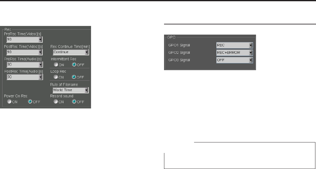
10
Administrator Setup (continued)
10
PowerOn Rec
Select if recording is started automatically when the
Memory Card Video Recorder is turned on.
ON: Power-on recording is enabled.
OFF: Power-on recording is disabled.
Record sound
Select if a beep sounds every minute during recording.
ON: A beep sounds.
OFF: A beep does not sound.
GPO
Select data to be output to GPO 1, 2, and 3.
OFF: Not output
REC: Recording status data are output.
ERROR: Error status data are output.
REC+ERROR: Recording and error status data are
output.
Note
Selectable setting for GPO3 is OFF or REC.
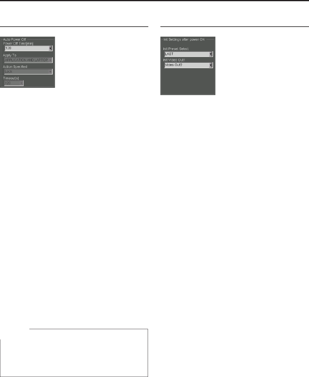
10
10
Administrator Setup (continued)
Auto Power OFF
Set the status after the Memory Card Video Recorder
is turned off.
Power Off Time
Select the time required from the ACC is turned off
up to the Memory Card Video Recorder is turned
off.
0, 10, 20, 30, 60, 90, 120, 180 (minutes): The
recorder is turned off after the specied time.
After Upload: The recorder is turned off after
uploading is nished.
Action after uploading is nished
When Power Off Time is set to After Upload, select
which action is to be taken by the subject(s) after
uploading is completed.
Apply To and Action Specied
Select which one's uploading is to be observed, and
the action to be taken
APPLICATION ONLY: Close
LAPTOP ONLY: Lock, Standby
APPLICATION AND LAPTOP: Lock Log off,
Shutdown, Stand by
Timeout[s]
The time required from the specied action is nished
until the recorder is turned off can be specied.
Setting values: 30, 60, 90, 120 (seconds)
Note
When the vehicle’s ignition switch is set to ACC-OFF with
Upload Mode on the File Transfer screen in Cong setup
set to MANUAL and Power Off Time on the Rec/Play
screen set to AUTO, uploading will start automatically.
Init Settings after power ON (Rec/Play)
Set the status after the Memory Card Video Recorder
is turned on.
Init Preset Select
Select a Preset setting.
Preset1, Preset2, Preset3: Either of Preset1,
Preset2, Preset3
LAST: The setting upon the last power-off will be
restored.
Init Video Out 1
Select which signal is to be output from the [VIDEO
OUT 1] connector of the Memory Card Video Recorder
as through output.
CAM1: Input signal to the [CAMERA 1] connector
CAM3: Input signal to the [CAMERA 3] connector
Video Out2: Encoded signal
LAST: The setting upon the last power-off will be
restored.
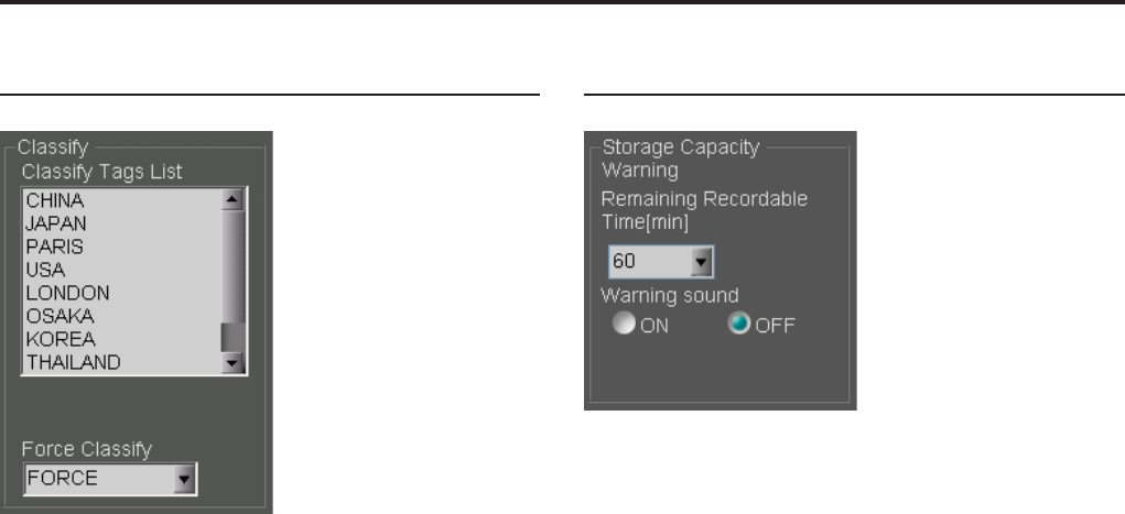
10
Administrator Setup (continued)
10
Classify
Classify Tag List
A list of the registered classify tags can be displayed.
Up to 50 classify tags can be registered.
Force Classify
Set if classify information is added by a user upon
completion of recording.
FORCE: Addition of classify information is always
required.
ENABLE: Addition of classify information is
permitted.
DISABLE: Addition of classify information is
prohibited.
Storage Capacity Warning
If Warning sound is set to ON, a short beep is to sound
twice every 30 seconds when the remaining recordable
time becomes shorter than the value set by Remaining
Recordable Time[min]. If the Warning sound is set to
OFF, no warning sounds.
Setting values: 30, 60, 90 (minutes)
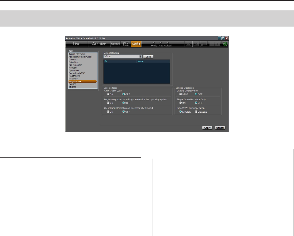
10
10
Administrator Setup (continued)
Meta Denition
Registering the meta denition
Create the setting les for Administrators, Ofcers,
Classify tags, etc., and store them on a USB memory
device. Then the stored les can be loaded from
the USB memory device to the Memory Card Video
Recorder as the following lists.
Administrators list
Ofcers list
Classify tags list
Agency list
Unit list
Shift list
Area list
VehicleID list
1. Connect the USB memory device in which
meta denitions are stored to:
In a case of the AG-CPD20P: PC
In a case of the AG-CPD15P: AG-CPD15P
2. Select the meta denition to be loaded from
the Meta Denition dropdown list.
3. Click on [Load].
The le selection dialog box appears.
4. Select a le to be loaded.
5. Click on [Open].
The specied meta denition is loaded and set for
the Memory Card Video Recorder.
The loaded meta denition is displayed in the list.
Notes
If no valid le is found on the USB memory device, the
settings on the Memory Card Video Recorder will be
cleared.
Up to 50 Classify tags can be loaded, but only the rst
10 tags will be registered on the Memory Card Video
Recorder.
This function is not available with the AG-CPD10CRUP.
Meta denition is loaded soon after the [OK] button
is clicked on, and clicking on the [Apply] button is not
required.
•
•
•
•
File format
Filename:
Any lename may be used.
Syntax:
Ofcer data les may contain no more than one
statement per line.
Multiple statements or denitions on one line are
invalid.
Line Feed Codes:
Line feeds are coded as the hexadecimal values 0Dh
0Ah or just 0Ah.
Blank Lines:
Blank lines are ignored. Aside from the line feed code,
a blank line may contain only space and tab (09h)
characters.
Comment Lines:
Lines beginning with "#" (ignoring leading spaces or
tabs) are considered to be comment lines. These have
no special meaning to the system, but may contain
notes or descriptions. Valid comment characters are
those from 20h to 7Eh.
Registration

10
Administrator Setup (continued)
10
Denition Lines:
An identier is a denition value.
These lines dene names and other data. Leading
spaces and tabs are ignored.
Identier descriptions are shown in the following table.
Sample les
Samples for the setting les are as shown below.
Administrator le
Identifier Max.
characters Description Classify
FirstName 50 Specify administrator's
first name
○
MiddleName 1 Specify administrator 's
middle initial
×
LastName 50 Specify administrator 's
last name
○
ID 50 Officer number for
authentication
○
Password 12 Specify the password. ×
Border 73 Borders may be
assigned to multiple
administrators.
Defined values are
ignored.
○
Border=------------------------------------
# Administrator setting le
FirstName=John
MiddleName=
LastName=Smith
ID=ICV12345
Password=pana1122
Border=------------------------------------
FirstName=Jane
MiddleName=
LastName=White
ID=ICV12346
Password=pana1234
Ofcer le
Identifier Max.
characters Description Classify
FirstName 50 Specify officer's first
name
○
MiddleName 1 Specify officer's
middle initial
×
LastName 50 Specify officer's last
name
○
ID 50 Officer number for
authentication
○
Password 12 Specify the password. ×
Border 73 Borders may be
assigned to multiple
officers. Defined
values are ignored.
○
Border=------------------------------------
# Ofcer setting le
FirstName=John
MiddleName=
LastName=Smith
ID=ICV12345
Password=pana1122
Border=------------------------------------
FirstName=Jane
MiddleName=
LastName=White
ID=ICV12346
Password=pana1234

10
10
Administrator Setup (continued)
Field name le
Identifier Max.
characters Description Classify
Field1 50 Specify field name of
Field1.
×
Field2 50 Specify field name of
Field2.
×
Field3 50 Specify field name of
Field3.
×
Field4 50 Specify field name of
Field4.
×
Field5 50 Specify field name of
Field5. The system
uses Field5 for
identifying a vehicle
so that the name like
Source, Vehicle, etc.
is recommended to be
used.
×
#------------------------------------
#Field name setting le
Field1=Agency
Field2=Unit
Field3=Shift
Field4=Area
Field5=VehicleID
Classify tags
Identifier Max.
characters Description Classify
Classify 99 Defines Classify tag. ○
#Border=------------------------------------
#Classify tag setting le
Classify=Classify1
Classify=Classify2
Classify=Classify3
Classify=Classify4
Classify=Classify5
Field le
Identifier Max.
characters Description Classify
Agency 50 Specify the value of
Field1.
○
Unit 50 Specify the value of
Field2.
○
Shift 50 Specify the value of
Field3.
○
Area 50 Specify the value of
Field4.
○
Source 50 Specify the value of
Field5.
○
#Border=------------------------------------
#Field List setting le
Agency=New York
Agency=Los Angeles
Agency=Dallas
Agency=San Diego
Agency=Chicago
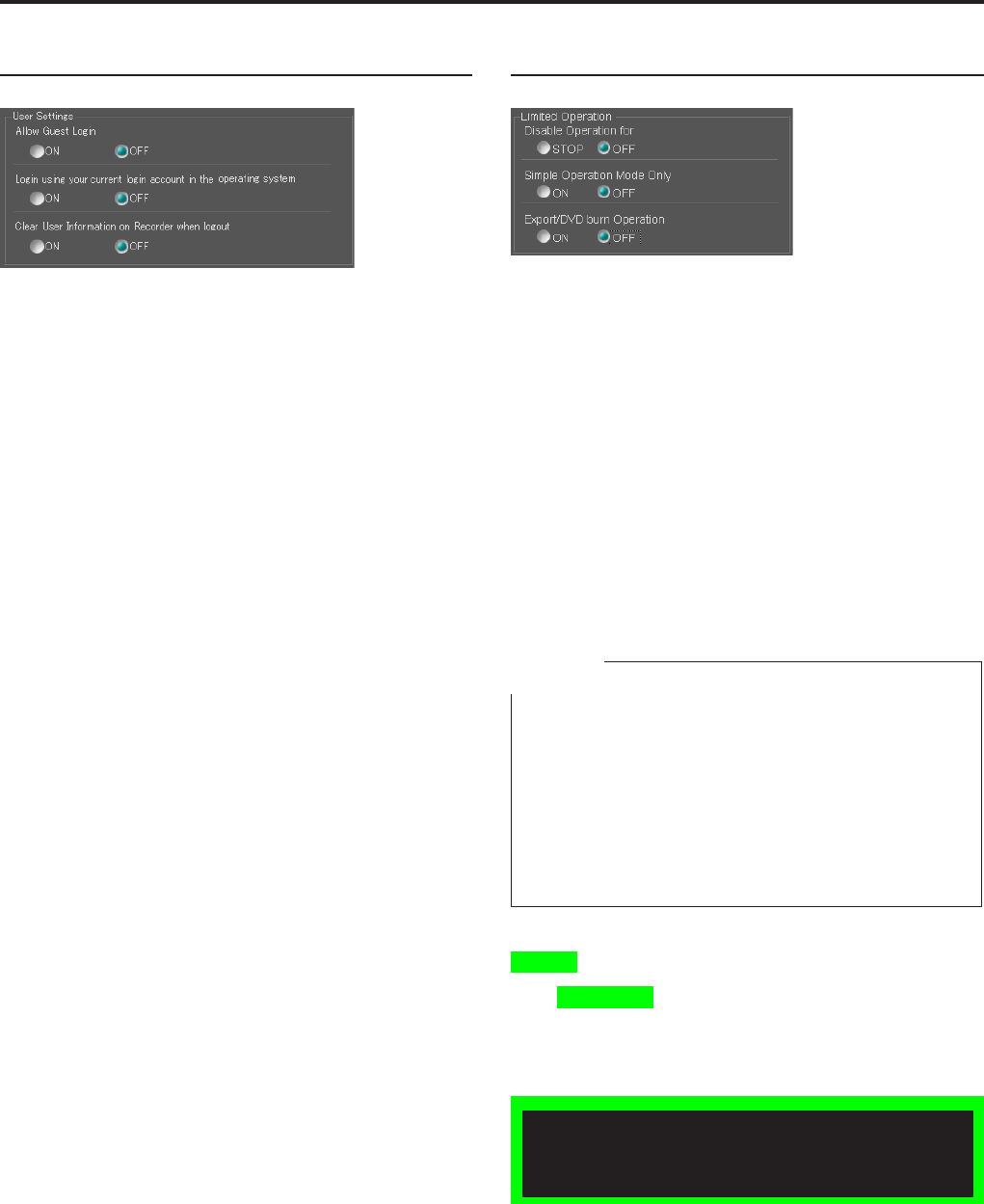
10
Administrator Setup (continued)
10
Exporting from the Front-End Application is not
available at present. Upgrading is scheduled for
the future.
User Settings
Allow Guest Login
Select if login of a user who has not been registered in
the Front-End application or the Memory Card Video
Recorder is permitted or not.
ON: Login is permitted. Entering of a password on
the Login screen is no longer required.
OFF: Login is not permitted.
Login using your current login account in
the operating system
When set to ON, if the current login user name to the
PC is the same as that to the Front-End application,
the login screen with the password entered will be
displayed. This allows you to omit password input.
Clear User Information on Recorder when
logout
Select if the user information is deleted upon logoff.
ON: Deleted
OFF: Not deleted
Limited Operation
Disable Operation for
Set the operation prohibited by a user.
STOP: Use of the STOP button is prohibited.
OFF: All operations are permitted.
Simple Operation Mode Only
This setting permits a user to use only Simple
Operation Mode display.
Regardless of this setting, the administrator can use
both Full and Simple Operation modes.
ON: A user can use only Simple Operation mode.
OFF: A user can use both Full and Simple
Operation modes.
Note
The setting for use of only Simple Operation mode is
enabled when the following two conditions are satised:
Administrators List is registered on the Registration
screen.
(See “Registration,” page 105.)
The user is logged in as an ofcer but not as an
administrator.
(See “Startup and Termination,” page 49.)
•
•
Export/DVD burn Operation
Set if export and DVD burn is permitted by a user.
ENABLE: Permitted
DISABLE: Not permitted
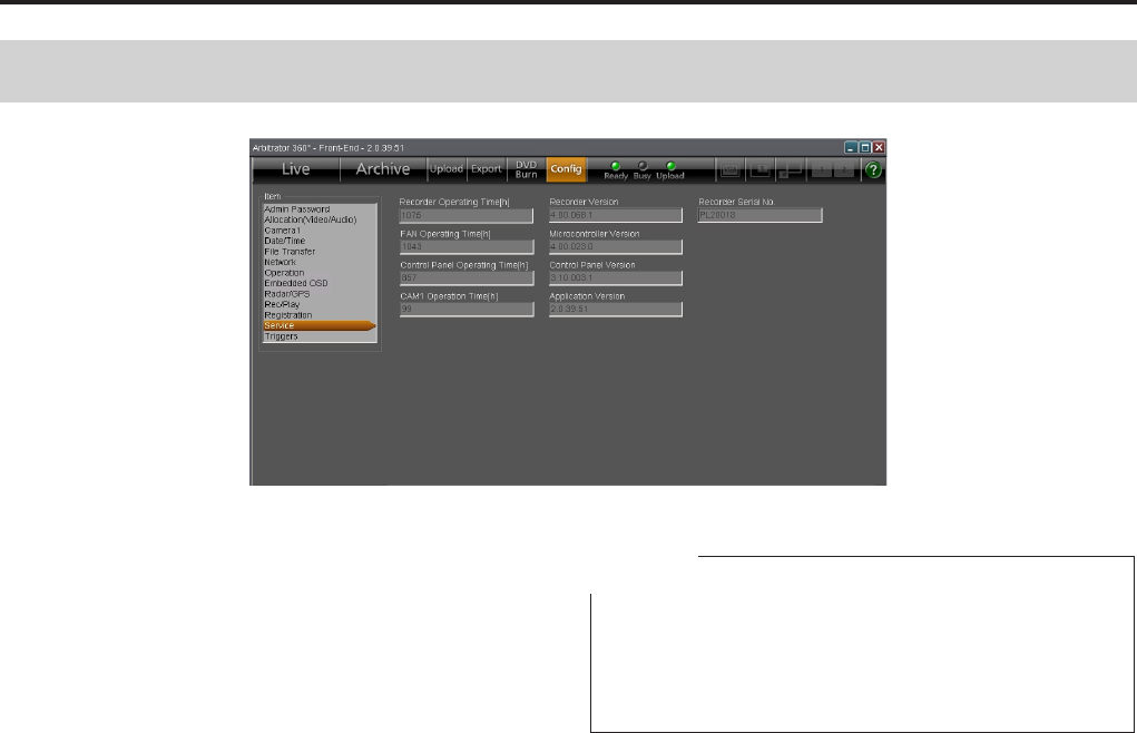
10
10
Administrator Setup (continued)
Recorder Operating Time [h]
Use this function to view the operating time of the
Memory Card Video Recorder.
Unit: Hour
FAN Operating Time [h]
Use this function to view the operating time of the fan.
Unit: Hour
Control Panel Operating Time [h]
Use this function to view the total operating time of the
Remote Control Panel.
CAM1 Operation Time [h]
Use this function to view the operating time of the color
camera.
Unit: Hour
Recorder Version
Use this function to view the rmware version of the
Memory Card Video Recorder.
Microcontroller Version
Use this function to view the version of the
microprocessor.
Control Panel Version
Use this function to view the version of the remote
control panel.
Application Version
Use this function to view the version of the Front-End
application.
Recorder Serial No.
Use this function to view the serial number of the
Memory Card Video Recorder.
Note
When the AG-CPD15P or AG-CPD10CRUP Memory
Card Video Recorder is used, BIOS Creation Date is
displayed to show the date and time when BIOS was
created.
Service
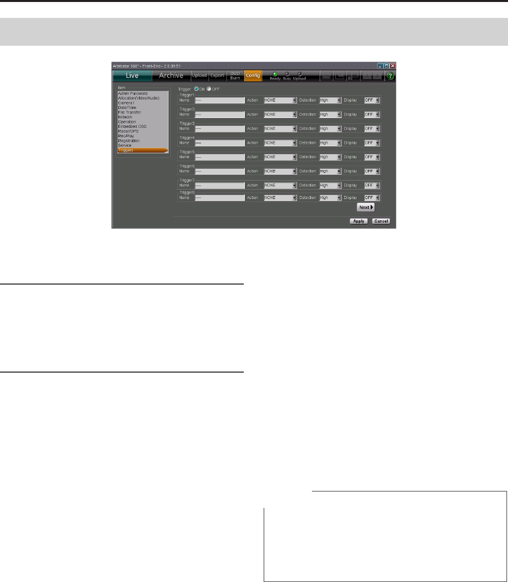
110
Administrator Setup (continued)
111
Trigger
Set if GPI triggers are used or not.
ON: The GPI triggers are used.
OFF: The GPI triggers are not used.
Trigger1-Trigger16
When GPI triggers are used, set the names, action
when a trigger is detected, detection conditions, and
trigger IDs to be displayed on the screen. Page 1 is the
setting screen for Triggers 1-8, and Page 2 is that for
Triggers 9-16. To change the setting screens, click on
the [Next] or [Prev] button.
Name
Specify a name with a maximum of 15 characters.
Action
Set an action to be taken when a trigger signal is
detected.
<Trigger 1-16>
NONE: No action
REC: Recording starts.
STOP: Recording stops.
AUTOZOOM: Automatic zooming is performed.
CAM1LED: The [REC] lamp of the color camera is
turned ON or OFF.
P1: Video specied in Preset1 is selected.
P2: Video specied in Preset2 is selected.
P3: Video specied in Preset3 is selected.
P1REC: Video specied in Preset1 is recorded.
P2REC: Video specied in Preset2 is recorded.
P3REC: Video specied in Preset3 is recorded.
AUDIO2ON: A signal input to [AUDIO IN 2] is
recorded.
AUDIO2MUTE: A signal input to [AUDIO IN 2] is
not recorded.
<Trigger 15, 16>
TGT(REC): Recording starts with a TGT input.
TGT(P1REC), TGT(P2REC), TGT(P3REC):
Video
specied in Preset1, Preset2, or Preset3 is
recorded with a TGT input.
OWN(REC): Recording starts with an OWN input.
OWN(P1REC), OWN(P2REC), OWN(P3REC):
Video
specied in Preset1, Preset2, or Preset3 is
recorded with an OWN input.
Notes
The TGT and OWN triggers are generated when the
speed of a target vehicle and your vehicle, respectively,
exceeds the specied speeds.
TGT and OWN can be set to either Trigger 15 or
Trigger 16, but not to both of them.
•
•
Triggers

110
111
Administrator Setup (continued)
Detection
Set the conditions for an action to be taken when a
trigger is detected.
<Trigger 1-16>
Low: Low-edge trigger
High: High-edge trigger
Both: Both-edge trigger
Level Low: Low-level trigger
Level High: High-level trigger
<With Triggers 15 and 16, when Action is set to TGT
or OWN>
Specify the speed of your or target vehicle. The unit is
MPH or km/h. Set the unit on the Radar/GPS screen in
Administrator Setup. The speed of a target vehicle can
be also specied with TGT on the Info tab.
Setting values: OFF, 1, 2, . . . 200
Display
Assign characters to be used in the Embedded OSD
display.
Setting values: A-Z, –, OFF (no display)
Note
The value set by Display appears when the state
triggered by Detection prevails. However, only when a
value "B" is set for Detection, the value set by Display
will appear during a high state.
112
113
This table shows the relationship between lamp Lit/Unlit/blinking states and the Memory Card Video Recorder's
operating status.
: Lit : Normal blinking : Unlit : Fast blinking (about three times/sec)
Lamp indication
Indicator Lamp
Recorder Status
REC
Ready
(Green)
Busy
(Red)
Upload
(Green)
Live video display
Normal recording
Postrecording
Administrator Setup screen displayed with recording stopped
Playing, exporting
Connecting the Memory Card Video Recorder to the Back-End server via the UPLOAD LAN
Uploading or exporting
Selecting a file for upgrading or copying menu settings
Just after selecting a file for upgrading or copying menu settings
• Upgrading or copying menu settings
• Restoring automatically
Finishing upgrading or copying menu settings
• No SDHC Memory Card is inserted, or it is not recognized.
• No more SDHC Memory Card space available
•
The write-protect switch of the SDHC Memory Card is set to "LOCK"
• An unformatted SDHC Memory Card
Notes
If pressing the [REC] button or entering a recording
trigger fails to start recording, the [REC] lamp blinks at
a high rate.
The [BUSY] lamp blinks when accessing to the SDHC
Memory Card immediately after opening or closing the
recorder's SDHC Memory Card slot cover.
•
•
Indicator Lamps and Recorder Status
Exporting from the Front-End Application is not
available at present. Upgrading is scheduled for
the future.
11
11
Setup
Admin Password
Enter your password.
Allocation (Video/Audio) setup
Perform video and audio settings.
Item Factory-Preset Description
Resolution/RecordRate The resolution and bit rate of the video can be set.
Main D1 HI The resolution and bit rate of the main video can be set.
Setting values: D1 HI, D1 STD, D1 10*1, CIF
Sub D1 HI The resolution and bit rate of the sub video can be set.
Setting values: D1 HI, D1 STD, D1 10*1, CIF
Connection Camera Camera connection can be set.
Camera1 ON The connection to the [CAMERA 1] connector can be set.
Setting values: ON, OFF
Camera2 ON The connection to the [CAMERA 2] connector can be set.
Setting values: ON, OFF
Camera3 OFF The connection to the [CAMERA 3] connector can be set.
Setting values: ON, OFF
Camera4 OFF The connection to the [CAMERA 4] connector can be set.
Setting values: ON, OFF
Camera5 OFF The connection to the [CAMERA 5] connector can be set.
Setting values: ON, OFF
Camera6 OFF The connection to the [CAMERA 6] connector can be set.
Setting values: ON, OFF
(to be continued to the next page)
Item Factory-Preset Description
Admin Password For inputting an administrator password.
Password admin
Retype Password
*1 If either the Main or Sub Resolution/RecordRec is
set to "D1 10", the other is also set to "D1 10".
11
Setup (continued)
11
Item Factory-Preset Description
Preset1*1Preset 1 can be set.
Form 1Channel The channel mode can be set.
Setting values: 1Channel, 2Channels, 4Channels QUAD, 4Channels
PANORAMA, 5Channels QUAD, 5Channels
PANORAMA, None
Pattern Main 1, Sub-
The combination of cameras displayed as Main and Sub videos can be set.
Setting values for Form and Pattern:
Form Pattern
1Channel Main 1, Sub -
Main 2, Sub -
Main 3, Sub -
2Channels Main 1, Sub 2
Main 1, Sub 3
Main 2, Sub 3
4Channels QUAD Main -, Sub 1456
Main -, Sub 2456
Main -, Sub 3456
4Channels PANORAMA Main -, Sub 1456
Main -, Sub 2456
Main -, Sub 3456
5Channels QUAD Main 1, Sub 2456
Main 1, Sub 3456
Main 2, Sub 3456
Main 3, Sub 2456*2
5Channels PANORAMA Main 1, Sub 2456
Main 1, Sub 3456
Main 2, Sub 3456
Main 3, Sub 2456*2
None*3
(to be continued to the next page)
*1 Selectable Form and Patter of Preset1, Preset2,
and Preset3 depend on the settings of Connection
Camera.
*2 This setting is enabled when the camera connected
to the [CAMERA 1] connector is set to OFF.
*3 "None" is not selectable for Preset1 unless all
camera connections are set to OFF.
11
11
Setup (continued)
Item Factory-Preset Description
Preset2*1Preset 2 can be set.
Form 1Channel The channel mode can be set.
Setting values: 1Channel, 2Channels, 4Channels QUAD, 4Channels
PANORAMA, 5Channels QUAD, 5Channels
PANORAMA, None
Pattern Main 2, Sub-
The combination of cameras displayed as Main and Sub videos can be set.
Setting values for Form and Pattern:
Form Pattern
1Channel Main 1, Sub -
Main 2, Sub -
Main 3, Sub -
2Channels Main 1, Sub 2
Main 1, Sub 3
Main 2, Sub 3
4Channels QUAD Main -, Sub 1456
Main -, Sub 2456
Main -, Sub 3456
4Channels PANORAMA Main -, Sub 1456
Main -, Sub 2456
Main -, Sub 3456
5Channels QUAD Main 1, Sub 2456
Main 1, Sub 3456
Main 2, Sub 3456
Main 3, Sub 2456*2
5Channels PANORAMA Main 1, Sub 2456
Main 1, Sub 3456
Main 2, Sub 3456
Main 3, Sub 2456*2
None*3
(to be continued to the next page)
*1 Selectable Form and Patter of Preset1, Preset2,
and Preset3 depend on the settings of Connection
Camera.
*2 This setting is enabled when the camera connected
to the [CAMERA 1] connector is set to OFF.
*3 "None" is not selectable for Preset1 unless all
camera connections are set to OFF.
11
Setup (continued)
11
Item Factory-Preset Description
Preset3*1Preset 3 can be set.
Form 2Channel The channel mode can be set.
Setting values:
1Channel, 2Channels, 4Channels QUAD, 4Channels
PANORAMA, 5Channels QUAD, 5Channels PANORAMA, None
Pattern Main 1, Sub 2
The combination of cameras displayed as Main and Sub videos can be set.
Setting values for Form and Pattern:
Form Pattern
1Channel Main 1, Sub -
Main 2, Sub -
Main 3, Sub -
2Channels Main 1, Sub 2
Main 1, Sub 3
Main 2, Sub 3
4Channels QUAD Main -, Sub 1456
Main -, Sub 2456
Main -, Sub 3456
4Channels PANORAMA Main -, Sub 1456
Main -, Sub 2456
Main -, Sub 3456
5Channels QUAD Main 1, Sub 2456
Main 1, Sub 3456
Main 2, Sub 3456
Main 3, Sub 2456*2
5Channels PANORAMA Main 1, Sub 2456
Main 1, Sub 3456
Main 2, Sub 3456
Main 3, Sub 2456*2
None*3
Audio In Select The audio inputs can be selected.
Audio1 Wireless Mic
The audio signal connected to the [AUDIO IN 1] connector can be selected.
Setting value: Mic (microphone)
Wireless Mic (wireless microphone)
Off (no connection)
Audio2 Mic
The audio signal connected to the [AUDIO IN 2] connector can be selected.
Setting value: Mic (microphone)
Wireless Mic (wireless microphone)
Off (no connection)
Audio3 OFF
The audio signal connected to the [AUDIO IN 3] connector can be selected.
Setting value: Mic (microphone)
Wireless Mic (wireless microphone)
Off (no connection)
Audio4 OFF
The audio signal connected to the [AUDIO IN 4] connector can be selected.
Setting value: Mic (microphone)
Wireless Mic (wireless microphone)
Off (no connection)
Init Audio Rec after
power ON
ON Initial audio output setting (upon power-on)
Setting values: ON, OFF, LAST*4
*1 Selectable Form and Patter of Preset1, Preset2,
and Preset3 depend on the settings of Connection
Camera.
*2 This setting is enabled when the camera connected
to the [CAMERA 1] connector is set to OFF.
*3 "None" is not selectable for Preset1 unless all
camera connections are set to OFF.
*4 The setting upon the last power-off will be restored
when the camera is turned on. If the Memory Card
Video Recorder is not turned off properly, the setting
data upon power-off may not be stored properly.
11
11
Setup (continued)
Camera1 setup
Camera1 settings can be performed.
Item Factory-Preset Description
Camera1 Settings for the color camera connected to the [CAMERA 1] connector
on the Memory Card Video Recorder
IR Level LOW Level setting for automatic IR switching*1
Setting values: LOW, HIGH
IR Time[s] 30 Level detection time for automatic IR switching*1 (seconds)
Setting values: 10, 30, 60, 300
Auto Zoom
Magnication
10 Maximum magnication setting for automatic zooming
Setting values: 1, 2, 3, 4, 5, 7, 10, 15, 22
Auto Zoom Time[s] 3 Keeping time of the maximum zoom magnication during automatic
zooming (seconds)
Setting values: 3, 5, 8
Auto Zoom End
Position
1 Automatic zooming end position setting
Setting values: 1, 2, 3, 4, 5, 7, 10, 15, 22, LAST
Zoom Limit 220 Maximum magnication during zoom
Setting values: 22, 220
AGC Level HIGH Automatic gain control setting for the color camera
Setting values: LOW, MID, HIGH, OFF
Flip OFF Vertical ipping of the output image from the color camera
Setting values: ON (vertically ipped)
OFF (No ipping)
Auto Focus PRESET The focusing method of the color camera in the following conditions can
be set:
•
When "Init LPR Mode" is set to "DISABLE"
•
When "Init LPR Mode" is set to "ENABLE" and "LPR Mode" is set to
"PATROL"
•
When recording is started by a recording trigger signal with "Init LPR
Mode" set to "ENABLE" and "LPR Mode" set to "LPR"
Setting values:
PRESET (When the zoom magnication is set to ×3 or less, the
camera focuses on an object at about 15 m distance from
the camera. If zooming operation is performed afterward,
automatic focusing will be activated.)
DISABLE (The focal position is xed at a distance of about 40 m,
and automatic focus is disabled.
AUTO (Auto focusing when zooming magnication changes)
*1 The [IR Level] and [IR Time] settings are enabled
only when [Init IR Mode] is set to "AUTO."
(to be continued to the next page)

11
Setup (continued)
11
*1 The setting upon the last power-off will be restored
when the camera is turned on. If the Memory Card
Video Recorder is not turned off properly, the setting
data upon power-off may not be stored properly.
*2 When [Init AE Shift] is set to "+2" and the subject
is dark, the number of frames to be updated per
second may become less than 30.
Item Factory-Preset Description
Init Camera1 Settings after power ON The initial settings upon startup of the color camera connected to the
[CAMERA 1] connector on the Memory Card Video Recorder can be set.
Init Backlight OFF Initial setting of backlight compensation
Setting values: ON, OFF, LAST*1
(The backlight compensation is enabled when set to
ON.)
Init IR Mode AUTO Infrared imaging function switching
Setting values: ON (The IR function is forcibly set to ON)
OFF (The IR function is forcibly set to OFF.)
AUTO (The IR function is automatically turned ON or
OFF.)
LAST*1
Init Camera1
LED
ON Initial setting of the [REC] lamp of the color camera
Setting values: ON (The lamp is lit during recording.)
OFF (The lamp does not light.)
LAST*1
Init AE Shift 0 Initial setting of the brightness for the color camera*2
Setting values: 2, 1, 0, -1, -2, LAST*1
Init LPR Mode DISABLE License Plate Recognition function switching
Setting values: ENABLE (LPR function enabled)
DISABLE (LPR function disabled. [LPR Mode] is
switched to "PATROL.".)

11
11
Setup (continued)
Date/Time setup
The date and time can be set.
Item Factory-Preset Description
Date/Time Date, time, and time zone settings
Time Zone Eastern
Daylight Saving
Time
Time zone
Hawaii Standard Time
Yukon Standard Time
Yukon Daylight Saving Time
Pacic Standard Time
Pacic Daylight Saving Time
Mountain Standard Time
Mountain Daylight Saving Time
Central Standard Time
Central Daylight Saving Time
Eastern Standard Time
Eastern Daylight Saving Time
Atlantic Standard Time
Atlantic Daylight Saving Time
Asia Tokyo
Date/Time Style USA Date/Time display style setting
Setting values: ISO ( YYYY-MM-DD HH : MM : SS)
USA ( MM/DD/YYYY HH : MM : SS)
Day/Night View Day/Night mode setting
Day/Night View
Auto Switch
Checked Select if Day and Night views are automatically switched or not.
Switch to Day View
at
7:00:00 AM Time setting for switching to Day mode
Setting range: 00:00:00 AM-11:59:59 PM
Switch to Night
View at
6:00:00 PM Time setting for switching to Night mode
Setting range: 00:00:00 AM-11:59:59 PM

10
Setup (continued)
11
File Transfer setup
File transfer settings can be performed.
Item Factory-Preset Description
Upload Upload settings
Auto Upload is
Enabled
Unchecked Select whether automatic uploading is enabled or not.
Server IP Address
for Manual Upload
- IP address of the Back-End Server during manual uploading
Export/DVD Burn Conrmation Select how to delete video les from the Memory Card Video Recorder
after data exporting or DVD burning.
Force: Automatically deleted
Conrmation: A conrmation message is displayed.
Certication
System Name - System name of the Memory Card Video Recorder.
Folder Folder settings
Snapshot To My Pictures Set a folder in which snapshot les are to be stored.
Exporting from the Front-End Application is not
available at present. Upgrading is scheduled for
the future.
10
11
Setup (continued)
Network setup
The network settings can be performed.
Item Factory-Preset Description
Streaming
IP Address - IP address setting for the Back-End server for streaming
Alert Streaming Checked When streaming is in progress in the Back-End application, that is
indicated on the Front-End application screen.
Resolution QCIF Resolution of video in streaming
Setting values: QCIF, CIF, D1
Recorder (PC LAN) Setting of the LAN port on the Memory Card Video Recorder for
connection with the Front-End server
DHCP*1Server1 Setting of whether the port will serve as a server or not
Setting values: OFF, Server1, Server2, Server3, Server4
Recorder (UPLOAD LAN) Setting of the wired LAN port on the Memory Card Video Recorder for
connection with the Back-End server
DHCP Client Setting of whether setting data will be obtained from the DHCP server or
not
Setting values: OFF, Client
Recorder (USB WIRELESS LAN) Setting of the wireless LAN port on the Memory Card Video Recorder for
connection with the Back-End server
DHCP Client Setting of whether setting data will be obtained from the DHCP server or
not
Setting values: OFF, Client
AP Priority AP Highest Set the priority of connection order to the access points.
Setting values: AP Highest, Random
*1 If Server1, Server2, Server3, or Server4 is selected,
the IP Address, Subnet Mask, and Gateway are
xed as shown below. If Off is selected, the IP
Address, Subnet Mask, and Gateway can be
changed.
Server1 Server2 Server3 Server4 OFF
IP Address 192.168.10.10 192.168.217.192 172.24.217.192 10.216.217.192 192.168.10.10
Subnet Mask 255.255.255.0 255.255.255.0 255.255.255.0 255.255.255.0 255.255.255.0
Gateway - - - - -
Streaming is not available at present. Upgrading
is scheduled for the future.

1
Setup (continued)
1
Embedded OSD setup
The settings for On-Screen Display can be performed.
Item Factory-Preset Description
Embedded OSD Setting of whether Embedded OSD is displayed or not
Main ON Embedded OSD display setting for the Main video
Setting values: ON, OFF
Sub ON Embedded OSD display setting for the Sub video
Setting values: ON, OFF
Display Position Upper-Left Setting of Embedded OSD display location
Setting values: Upper-Left (At the upper left)
Upper-Right (At the upper right)
Bottom-Left (At the bottom left)
Bottom-Right (At the bottom right)
Embedded OSD Item Settings of display items
Time ON Date/Time display setting
Setting values: ON, OFF
Trigger ON Embedded OSD display when trigger signals (GPI1-16) are input
Setting values: ON, OFF
VehicleID@Area OFF Setting of whether the vehicle identication data and location name are
displayed
Setting values: ON, OFF

1
1
Setup (continued)
Radar/GPS setup
Settings related with a radar gun and GPS
Item Factory-Preset Description
Radar Settings related with a radar gun*1
Connection of
Radar
OFF Device to which a radar gun is connected*1
Setting values: Recorder, OFF
Model Select ProLaser3 Model selection of the radar gun
Setting values: ProLaser3
STALKER_DUAL
GOLDEN_EAGLE_II
GPS GPS-related settings
Connection of GPS Recorder Device to which the GPS is connected
Setting values: Recorder, OFF
Collection Time [s] 1 Intervals of GPS data collection (seconds)
Setting values: 1, 2, 5, 10
Rec Start Information
Speed Unit MPH Unit of the speed of your vehicle
Setting values: MPH, km/h
*1 When a radar gun is used, consult your supplier.

1
Setup (continued)
1
Rec/Play setup
The settings related with recording and playback can be performed.
Item Factory-Preset Description
Rec Recording-related settings
PreRec Time
(Video)[s]
30 Video prerecording time (seconds)
Setting values: 0, 10, 20, 30, 60, 90
PostRec Time
(Video)[s]
0 Video post-recording time (seconds)
Setting values: 0, 10, 20, 30, 60, 90
PreRec Time
(Audio)[s]
0 Audio prerecording time (seconds)
Setting values: 0, 3, 10, 20, 30, 60, 90
PostRec Time
(Audio)[s]
0 Audio postrecording time (seconds)
Setting values: 0, 3, 10, 20, 30, 60, 90
Rec Continue Time
[min]
Continue Recording duration (minutes)
Setting values: Continue, 1, 2, 5, 10, 15, 20, 30, 60, 90
Intermittent Rec OFF Intermittent recording
Setting values: ON, OFF
Loop Rec OFF Loop recording
Setting values: ON, OFF
Rule of Filename World Time Rules of lename for recording les
Setting values: World Time
Local Time
Power On Rec OFF Automatic start of recording upon power-on
Setting values: ON, OFF
Record sound OFF Setting of a beep during recording
Setting values: ON, OFF
GPO GPO settings
GPO1 Signal OFF Setting of output signals to GPO1
Setting values: OFF, REC, ERROR, REC+ERROR
GPO2 Signal OFF Setting of output signals to GPO2
Setting values: OFF, REC, ERROR, REC+ERROR
GPO3 Signal OFF Setting of output signals to GPO3
Setting values: OFF, REC
Auto Power Off Settings upon automatic power-off
Power Off Time
[min]
After Upload
Time required from the signal is turned off up to the Memory Card Video
Recorder is turned off (minutes)
Setting values:
0, 10, 20, 30, 60, 90, 120, 180, After Upload
Apply To APPLICATION
AND LAPTOP
When Power Off Time is set to After Upload, select which one's
uploading is to be observed.
Setting values: APPLICATION ONLY, LAPTOP ONLY, APPLICATION
AND LAPTOP
Action Specied Lock
When Power Off Time is set to After Upload, select an action.
Setting values: Close, Lock, Log off, Shutdown, Stand by
Timeout [s] 120 When Power Off Time is set to After Upload, select time required for
the Memory Card Video Recorder to shut itself off after the specied
action. (Seconds)
Setting values: 30, 60, 90, 120
(to be continued to the next page)

1
1
Setup (continued)
Item Factory-Preset Description
Init Settings after power ON Initial settings upon power-on
Init Preset Select*1Preset1 Initial Preset setting
Setting values: Preset1, Preset2, Preset3, LAST*2
Init Video Out 1*1VIDEO_OUT 2 Setting of the throughout video signal to the [VIDEO OUT 1] connector
Setting values: CAM1, CAM3, Video OUT2, LAST*2
Force Classify Classify information setting
Force Classify DISABLE Addition of classify information
Setting values: DISABLE (No addition)
ENABLE (Addition permitted)
FORCE (Forcible addition)
Storage Capacity Warning
Remaining
Recordable
Time[min]
60 A warning sounds when the remaining recordable time becomes
shorter than the value set here.
Setting values: 30, 60, 90 (minutes)
Warning sound OFF Select if a short beep is to sound twice every 30 seconds when the
remaining recordable time becomes shorter than the set value.
Setting values: ON, OFF
*1 Depending on the settings of the Video Allocation
screen, some items may not be displayed.
*2 The setting upon the last power-off will be restored
when the camera is turned on. If the Memory Card
Video Recorder is not turned off properly, the setting
data upon power-off may not be stored properly.

1
Setup (continued)
1
Registration setup
Various data can be registered.
Item Factory-Preset Description
Meta Denition
Administrator
Select the type of meta denition to be registered to the Memory Card
Video Recorder.
Setting values: Administrator, Ofcer, Classify, Field1, Field2, Field3,
Field4, Field5
Allow Guest Login OFF Select if login of a user who has not been registered in the Back-End
Server or the Memory Card Video Recorder is permitted or not.
Setting values: ON, OFF
Login using your
current login account in
the operating system
OFF Select whether the login screen with the password entered will be
displayed upon startup.
Setting values: ON, OFF
Clear User Information
on Recorder when
logout
OFF Select if the user information of the Memory Card Video Recorder is
deleted upon logoff.
Setting values: ON, OFF
Disable Operation for OFF Set the operation prohibited by a user.
Setting values: STOP, OFF
Simple Operation Mode
Only
OFF Select if only Simple Operation mode screen is permitted by a user or
not.
Setting values: ON, OFF
Export/DVD Burn
Operation
DISABLE Set if export and DVD burn is permitted by a user.
Setting values: ENABLE, DISABLE
Exporting from the Front-End Application is not
available at present. Upgrading is scheduled for
the future.

1
1
Setup (continued)
Triggers setup
The trigger signals (GPI1-16) can be set.
Item
Factory-Preset
Description
Trigger ON Set if the GPI trigger function is used or not.
Setting values: ON, OFF
Name - Enter a GPI trigger name.
Action NONE Action when a trigger signal (GPI1-16) is detected.
Setting values:
NONE (No action)
REC (recording), STOP (stop)
AUTOZOOM ( Automatic zoom-in, pause for a specied time, then
zoom-out)
CAM1LED ( Switching [lit/unlit] of the [REC] lamp of the color
camera connected with the [CAMERA 1] input
connector)
Preset1 ( Preset1 input selected)
Preset2 ( Preset2 input selected)*1
Preset3 ( Preset3 input selected)*1
Preset1Rec ( Recording of Preset1 input video)
Preset2Rec ( Recording of Preset2 input video)*1
Preset3Rec ( Recording of Preset3 input video)*1
AUDIO2ON*2 ( Recording of [AUDIO IN2] input)
AUDIO2MUTE*2 ( No recording of [AUDIO IN2] input)
TGT(REC) (Recording starts upon a TGT input.)*3
TGT(P1REC) (Recording of input signals set in Preset1 starts
upon a TGT input.)*3
TGT(P2REC) (Recording of input signals set in Preset2 starts
upon a TGT input.)*1,*3
TGT(P3REC) (Recording of input signals set in Preset3 starts
upon a TGT input.)*1,*3
OWN(REC) (Recording starts upon a OWN input.)
OWN(P1REC) (Recording of input signals set in Preset1 starts
upon an OWN input.)*3
OWN(P2REC) (Recording of input signals set in Preset2 starts
upon an OWN input.)*1,*3
OWN(P3REC) (Recording of input signals set in Preset3 starts
upon an OWN input.)*1,*3
Detection High Detection method for trigger signals (GPI1-16)
The selectable detection methods vary, depending on the Action setting.
•
In a case of REC, Preset1Rec, Preset2Rec, Preset3Rec
Setting values: High (High-edge trigger)
Level High (High-level trigger)
Low (Low-edge trigger)
Level Low (Low-level trigger)
Both (Both-edge trigger)
•
In a case of
Preset
1,
Preset
2,
Preset
3, CAM1LED, AUTOZOOM, AUDIO2ON,
or STOP
Setting values: High (High-edge trigger)
Low (Low-edge trigger)
Both (Both-edge trigger)
•
In a case of
TGT(REC), TGT(P1REC), TGT(P2REC), TGT(P3REC),
OWN(REC), OWN(P1REC), OWN(P2REC), or OWN(P3REC)
Setting values: OFF, 1, 2, . . . 200
•
In a case of NONE
Setting values: High (High-edge trigger)
Low (Low-edge trigger)
Display OFF
Character denition when one character is displayed as an Embedded OSD
Setting values: A-Z, –, OFF
*1 These may not be selected if Preset2 or Preset3 is
not specied on the Allocation (Video/Audio) screen.
*2 These cannot be selected if Audio2 on the
Allocation(Video/Audio) screen is set to OFF.
*3 Selectable only for Trigger15 and 16

1 1
No. Message Measure
E00410 Invalid update file was found. The update file on the USB memory device is corrupted.
•
Check whether the update file for the recorder has been correctly copied
to the USB memory device.
•
Reformat the SDHC Memory Card or USB memory device before use.
•
Use another USB memory device.
E00411 Update file was not found. No update file could be found on the USB memory device.
•
Check whether the update file for the recorder has been correctly copied
to the USB memory device.
•
Reformat the SDHC Memory Card or USB memory device before use.
•
Use another USB memory device.
E00412 Two or more update files were
found. Multiple update files were found on the USB memory device.
•
Check whether there are multiple update files on the USB memory device.
•
Check whether there are multiple USB memory devices containing update
files.
E00413 Invalid update file was found. The update file on the USB memory device is corrupted.
•
Check whether the update file for the recorder has been correctly copied
to the USB memory device.
•
Reformat the SDHC Memory Card or USB memory device before use.
•
Use another USB memory device.
E00414
E00415
E00418 Update file was not found. No update file could be found on the USB memory device.
•
Check whether the update file for the recorder has been correctly copied
to the USB memory device.
•
Reformat the SDHC Memory Card or USB memory device before use.
•
Use another USB memory device.
E00419 This media cannot be used for
update. The used USB memory device cannot be used for updating.
•
A USB memory device containing a folder other than the
\WIDKEY folder cannot be used for updating.
E00420 Update file cannot be read. An update file load error occurred.
•
Check whether the update file for the recorder has been correctly copied
to the USB memory device.
•
Reformat the SDHC Memory Card or USB memory device before use.
•
Use another USB memory device.
E00449 Unexpected update failure was
found.
Some other update error occurred.
•
Check whether the update file for the recorder has been correctly copied to
the USB memory device.
•
Reformat the SDHC Memory Card or USB memory device before use.
•
Use another USB memory device.
E00460 Invalid update file was found. The update file on the USB memory device is corrupted.
•
Check whether the update file for the recorder has been correctly copied
to the USB memory device.
•
Reformat the SDHC Memory Card or USB memory device before use.
•
Use another USB memory device.
Error Messages
Messages Common to the Memory Card Video Recorder

1
Error Messages (continued)
1
No. Message Measure
E00461 Update file was not found. No update file could be found on the USB memory device.
•
Check whether the update file for the recorder has been correctly copied
to the USB memory device.
•
Reformat the SDHC Memory Card or USB memory device before use.
•
Use another USB memory device.
E00462 Two or more update files were
found. Multiple update files were found on the USB memory device.
•
Check whether there are multiple update files on the USB memory device.
•
Check whether there are multiple USB memory devices containing update
files.
E00463 Invalid update file was found. The update file on the USB memory device is corrupted.
•
Check whether the update file for the recorder has been correctly copied
to the USB memory device.
•
Reformat the SDHC Memory Card or USB memory device before use.
•
Use another USB memory device.
E00464
E00465
E00466 Unexpected update failure was
found.
Some other update error occurred.
•
Check whether the update file for the recorder has been correctly copied to
the USB memory device.
•
Reformat the SDHC Memory Card or USB memory device before use.
•
Use another USB memory device.
E00467
E00468 Update file was not found. No update file could be found on the USB memory device.
•
Check whether the update file for the recorder has been correctly copied
to the USB memory device.
•
Reformat the SDHC Memory Card or USB memory device before use.
•
Use another USB memory device.
E00469 This media cannot be used for
update. The used USB memory device cannot be used for updating.
•
A USB memory device containing a folder other than the
\WIDKEY folder cannot be used for updating.
E00470 Update file cannot be read. An update file load error occurred.
•
Check whether the update file for the recorder has been correctly copied
to the USB memory device.
•
Reformat the SDHC Memory Card or USB memory device before use.
•
Use another USB memory device.
E00499 Unexpected update failure was
found.
Some other update error occurred.
•
Check whether the update file for the recorder has been correctly copied to
the USB memory device.
•
Reformat the SDHC Memory Card or USB memory device before use.
•
Use another USB memory device.
E00602 AG-RCP30 needs to be updated!
Will start updating soon.
A connected AG-RCP30 was found to need an update.
The Remote Control Panel reboots automatically to start an update.
E00603 Unsupported Control Panel!
Replace Control Panel.
A Remote Control Panel not supported by the Memory Card Video Recorder
was detected.
Disconnect the Remote Control Panel.
E00604 Will power off after uploading.
Turn ACC ON to cancel power off.
The vehicle engine switch is set to LOCK (OFF) when "PowerOff Time" on page
103 is set to "After Upload." The system awaits that uploading is finished, that the
connection with the Back-End application is released, or uploading, streaming,
administrator setup, or upgrading on the Back-End application is finished. To
continue using the Memory Card Video Recorder without turning it off, set the
engine switch to ON.

Error Messages (continued)
10
11
No. Message Measure
E02431 DSP error.
This system is rebooting. Wait until the error message is cleared. Contact your supplier if the
message does not clear after about a minute.
E02432
E02440 System error.
Couldn't format cards. Insert another SDHC Memory Card.
E02441
Couldn’t format cards.
E02442 Write Protect cards found.
Couldn't format. Disable SDHC Memory Card write-protection.
E02444 No SDHC Cards found.
Couldn't format. Insert an SDHC Memory Card.
E02460 System error.
Couldn't delete files. Contact your supplier.
E02461 Couldn't delete files. Check the card information, and proceed as follows according to the
information.
CARD PROTECT:
Disable SDHC Memory Card write-protection.
UNFORMATTED:
Replace with the formatted SDHC Memory Card.
NO CARD:
Insert an SDHC Memory Card.
Others:
Replace the SDHC Memory Card with another one.
E02470 System error.
Couldn't restore files. Contact your supplier.
E02471 Couldn't restore files.
E02481 Write error on slot1.
Record cannot be continued. Be sure to use the correct procedure to remove and load SDHC Memory
Cards. Replace an SDHC Memory Card that is not recognized after
inserting it in the SDHC Memory Card slot and closing the SDHC Memory
Card slot cover.
E02482 Write error on slot2.
Record cannot be continued.
E02483 Write error on slot3.
Record cannot be continued.
E02484 Write error on slot4.
Record cannot be continued.
E07671 CAMERA1
communication error.
Please check the CAMERA1.
The Color Camera may not be correctly connected to the Memory Card Video
Recorder. Check whether the camera cable (included in the Color Camera) is
correctly connected to the Color Camera. Contact your supplier if this measure
does not solve the problem.
E08601 Playback and record cannot be
executed. Close the SDHC Memory Card slot cover.
E08602 The recorder’s fan has stopped. Contact your supplier.
E10400 Radar model file was not found.
E10401 More than 10 radar model files
were found.
E10402
Invalid radar model file was found.
E10403 Radar model file cannot be read.
E10410
Radar communication error.
Please check the radar setting.

10
Error Messages (continued)
11
No. Message Measure
E15751 VUP Card found on slot1.
Record cannot be started. A card for upgrading is inserted. Data cannot be written to the card.
E15752 VUP Card found on slot2.
Record cannot be started.
E15753 VUP Card found on slot3.
Record cannot be started.
E15754 VUP Card found on slot4.
Record cannot be started.
E15755 Unsupported Card found on slot1.
Record cannot be started. The inserted card cannot be used. Check card type.
E15756 Unsupported Card found on slot2.
Record cannot be started.
E15757 Unsupported Card found on slot3.
Record cannot be started.
E15758 Unsupported Card found on slot4.
Record cannot be started.
E15759
Unformatted Card found on slot1.
Record cannot be started.
An unformatted SDHC Memory Card has been inserted.
Format the SDHC Memory Card using the Memory Card Video Recorder or
"SDHC Memory Card Formatting Software," or replace it with a formatted
SDHC Memory Card. You can download the "SDHC Memory Card
Formatting Software" from the Web site shown below:
http://panasonic.jp/support/global/cs/sd/download/sd_formatter.html
E15760
Unformatted Card found on slot2.
Record cannot be started.
E15761
Unformatted Card found on slot3.
Record cannot be started.
E15762
Unformatted Card found on slot4.
Record cannot be started.
E15763 Write Protect Card found on slot1.
Record cannot be started. The write-protect switch of the SDHC Memory Card is set to "LOCK." Slide
the write-protection switch away from the "LOCK" position.
E15764 Write Protect Card found on slot2.
Record cannot be started.
E15765 Write Protect Card found on slot3.
Record cannot be started.
E15766 Write Protect Card found on slot4.
Record cannot be started.
E15767 No SDHC Cards found.
Record cannot be started. No SDHC Memory Card is inserted. Insert an SDHC Memory Card.
E15768 Write Error.
Record cannot be started. Data cannot be written to the SDHC card. Replace the SDHC Memory Card.
E15769 Card Full.
Record cannot be started. The following conditions may have occurred:
•
There is no space left on the SDHC Memory Card.
•
Files contained in one of the SDHC Memory Cards inserted in the SDHC
Memory Card slots 1, 2, 3, and 4 exceed 5,000 files.
Replace the SDHC Memory Card with an SDHC Memory Card with free capacity,
or free up space of 10 Mbytes or more in the SDHC Memory Card for new data.
E20801 Recorder reboots by
unrecoverable card ejection error. Be sure to use the correct procedure to remove and load SDHC Memory
Cards.
E20802 Please reinsert the card or reboot
the system. Check the SDHC Memory Card and re-insert it, or reboot the Memory Card
Video Recorder.
E20901 Firmware Update FAILED! An error occurred during the update.
•
Check whether the update file for the recorder has been correctly copied
to the USB memory device.
•
Reformat the SDHC Memory Card or USB memory device before use.
•
Use another USB memory device.
•
Check whether there are multiple update files on the USB memory device.
•
Check whether there are multiple USB memory devices containing update
files.
•
A USB memory device containing a folder other than the \WIDKEY folder
cannot be used for updating.

Error Messages (continued)
1
1
No. Message Measure
E20911 Microcontroller Update FAILED!
An error occurred during the update.
The Memory Card Video Recorder reboots automatically to restart an
update.
Contact your supplier if the problem persists.
E20912 Unsupported Microcontroller
Detected! The Memory Card Video Recorder has broken down.
Contact your supplier.
E20921 AG-RCP30 Update FAILED!
An error occurred during an update of an AG-RCP30 connected to the
Memory Card Video Recorder.
The Memory Card Video Recorder reboots automatically to restart an update.
Contact your supplier if the problem persists.
E20922 Unsupported Control Panel
Detected! A Remote Control Panel not supported by the Memory Card Video Recorder
was detected.
Disconnect the Remote Control Panel.
E22420 Officer’s information file cannot be
loaded.
The officer data file (WID**
***
.TXT) is corrupted. Create a new officer’s data file,
save it to a USB memory device and re-register it.
E22421
Since you are not an administrator,
you cannot open this menu.
You are not registered as an administrator and cannot open this menu. Ask a
registered administrator for assistance.
E22422 Officer’s information file cannot be
loaded.
There is no Officer Registration file or it contains the wrong data. Create a
correct Officer Registration file (WOFFICER.TXT), copy it to a USB memory
device and reload it.
E22423 Admin’s information file cannot be
loaded.
There is no Administrator Registration file or it contains the wrong data. Create
a correct Administrator Registration file (WADMIN.TXT), copy it to a USB
memory device and reload it.
E22425
Classification list cannot be loaded.
There is no classify file or the content of the file is incorrect.
E22426 Menu copy failed. For copying to a USB memory device, connect a write-enabled USB
memory device. For copying to a recorder, connect a USB memory device
that contains data.
E22427 Source information file cannot be
loaded. There is no vehicle ID registration file or the content of the file is incorrect.
E22428 Shift information file cannot be
loaded. There is no shift file or the content of the file is incorrect.
E22429 Area information file cannot be
loaded. There is no area registration file or the content of the file is incorrect.
E22432 Service log copy failed. Copying service log is failed. Retry copying.
E22448 Operation was canceled to start
streaming. Streaming starts, and the operation is canceled. Wait until streaming ends.
E25410
GPS communication error.
Please check the GPS module.
An error occurred in the GPS module. Contact your supplier.
E27200
FinishUpload
File transfer was completed.
E27201 Storage capacity was not enough
to transfer the file.
Capacity of the server is not enough for uploading data, and upload is canceled.
E27202 File transfer was completed.
Restore file remained. Upload was completed, but video files not restored remain on the SDHC
Memory Card.
E27203 File not found in SDHC cards. No file for uploading is found on an SDHC Memory Card.
E27401 Write Protect cards found.
Couldn’t start file transfer. A read-only SDHC Memory Card is found, and uploading cannot be started.
E27403 Media error.
File transfer was incomplete.
A read/write error has occurred on the media. Replace the SDHC Memory Card.
E27405 Storage write error.
File transfer was incomplete.
A verifying error has occurred in the server storage, and upload cannot be completed.
E27407 No SDHC Cards found.
Couldn’t start file transfer. No SDHC Memory Card is inserted, and upload cannot be started.

1
Error Messages (continued)
1
No. Message Measure
E27430 Couldn’t start file transfer. Upload cannot be started. Check the network connection.
E27431 File transfer was incomplete. Upload cannot be completed because of the network trouble.
E27499 System error.
File transfer was incomplete. A system error has occurred, and upload cannot be completed.
E28200 FinishExport. Export was completed.
E28201 USB storage capacity was not
enough to export. Use other USB memory device that is not full.
E28202 Export was completed.
Restore file remained. Restore the file not yet restored, and export it again.
E28203 File not found in SDHC cards.
There are no files to export. No export operation needed.
E28400 No USB storage devices found.
Couldn’t start export. Connect a USB memory device.
E28401 Write Protect cards found.
Couldn’t start export. Disable SDHC Memory Card write-protection.
E28402
All USB storages are read only.
Couldn’t start export.
Connect a write-enabled USB memory device.
E28403 Media error.
Export was incomplete. Replace the SDHC Memory Card or the USB memory device.
E28404
USB storage file system error.
Couldn’t start export.
Replace the USB memory device.
E28405 USB storage write error.
Export was incomplete.
E28406 Found update file in USB storage.
Couldn’t start export. Delete the update file on the USB memory device.
E28407 No SDHC Cards found.
Couldn’t start export. Insert an SDHC Memory Card with recorded files.
E28409 Couldn’t start export. Replace the SDHC Memory Card.
E28499 System error.
Export was incomplete. Reboot the recorder.
E28880 USB storage was ejected.
Export was incomplete.
Do not remove the USB memory device while exporting data. Reconnect the
USB memory device and export again.
E28881 USB storage was inserted.
Export was incomplete. Export the data again.
E29400 Unsupported camera connection.
A camera is connected only to the [CAMERA 4], [CAMERA 5], or [CAMERA 6]
connector. Check the input.
E29401 No CAMERA1 video signal. [CAMERA 1] connector input cannot be detected. Check whether the signal
is input to the [CAMERA 1] connector.
E29402 No CAMERA2 video signal. [CAMERA 2] connector input cannot be detected. Check whether the signal
is input to the [CAMERA 2] connector.
E29403 No CAMERA3 video signal. [CAMERA 3] connector input cannot be detected. Check whether the signal
is input to the [CAMERA 3] connector.
E29404 No CAMERA4 video signal. [CAMERA 4] connector input cannot be detected. Check whether the signal
is input to the [CAMERA 4] connector.
E29405 No CAMERA5 video signal. [CAMERA 5] connector input cannot be detected. Check whether the signal
is input to the [CAMERA 5] connector.
E29406 No CAMERA6 video signal. [CAMERA 6] connector input cannot be detected. Check whether the signal
is input to the [CAMERA 6] connector.
E30400 Network setting parameter error. Network settings are not correct. Check the network settings.

Error Messages (continued)
1
1
Messages Unique to the Front-End Application
Error Messages 30200 and after are the command error of the Memory Card Video Recorder.
No. Message Measure
20004 There is no response form the
recorder. Connection with the recorder was interrupted.
• Check that the LAN cable is connected to the recorder.
• Check that the recorder is turned on.
20006 Application cannot communicate
with Recorder, please check
connections.
The application could not communicate with the recorder.
• Check that the LAN cable is connected to the recorder.
• Check that the recorder is turned on.
• Check that the network setting is correct.
20015 Cannot start recording due to no
live mode. Recording could not be started.
• Start recording after entering Live mode.
20019 The application failed
communication with the recorder. The command could not be transmitted to the recorder.
• Check that the LAN cable is connected to the recorder.
• Check that the recorder is turned on.
20021 There was no same time of
bookmark.
20022 There was no same time of
classify.
20028 Cannot operate bookmark
because there already existed
classify.
A bookmark cannot be created within 2 seconds before or after a classify
tag.
• Create a bookmark 2 seconds or more apart from a classify tag.
20029 Cannot operate bookmark
because there already existed
bookmark.
A bookmark cannot be created within 2 seconds before or after another
bookmark.
• Create bookmarks 2 seconds or more apart from each other.
20033 Cannot operate classify because
there is already bookmark. A classify tag cannot be created within 2 seconds before or after a
bookmark.
• Create a classify tag 2 seconds or more apart from a bookmark.
20037 Failed in creating the snapshot
file. Creation of a snapshot file failed.
• Check that there is sufficient free space in the destination medium.
• If the file is to be stored in a removable medium, check that the removable
medium has been inserted.
20051 The file is invalid. The setting file is invalid.
• Specify the file that was created as a setting master.
20052 The file may be tampered with. The file may have been tampered with or damaged.
20053 Skipped uploading the video file
because Back-End Server was
busy. Try again later.
Upload could not be started because the server is in processing.
• Retry later.
20054 Failed to transfer the file. Connection with the recorder was failed.
• Check that the FE and BES are connected through LAN.
• Check that the recorder is turned on.
• Check that the network settings of the FE and BES are properly made.
20055 Failed in the output of the file.
The free space at the output
destination is insufficient or there
is a possibility that the output
destination is inhibited to write.
File output (export, upload, or DVD burn) failed.
• Check that there is sufficient free space in the destination medium.
• Check if the medium is write-protected.
• Check that writing to the destination medium by Windows is authorized.
20056 Failed to transfer file from
Recorder. No video file could be found on the recorder.
• Check that the LAN connection to the recorder is properly made.
20057 Failed to transfer file from
Recorder. During file output (export, upload, or DVD burn), file transfer from the
recorder failed.
• Check that the LAN cable is connected to the recorder.
• Check that the recorder is turned on.

1
Error Messages (continued)
1
No. Message Measure
20058 Failed in connection with the
Back-End Server. The FE could not communicate with the BES.
• Check that the FE and BES are connected through LAN.
• Check that the network settings of the FE and BES are properly made.
• Check if communication is interrupted by a firewall.
20059 The output path was not found. During file output (export, upload, or DVD burn), file transfer from the
recorder failed.
• If the file is to be output to a removable medium, check that the removable
medium has been inserted.
• Check if the medium is write-protected.
• Check that writing to the destination medium by Windows is authorized.
20060 Failed to open or create the file. During file output (export, upload, or DVD burn), creation of an output file
failed.
• Check that there is sufficient free space in the destination medium.
• Check if the medium is write-protected.
• Check that writing to the destination medium by Windows is authorized.
20061 Disconnected the recorder while
exporting. During exporting or DVD burning, communication with the recorder was
interrupted.
• Check that the LAN cable is connected to the recorder.
• Check that the recorder is turned on.
20067 Fatal error. An error was generated.
A program bug is suspected.
20068 Failed. An error whose cause could not be specified was generated.
20071 Cannot operate classify because
there already existed classify. A classify tag cannot be created within 2 seconds before or after another
classify tag.
• Create classify tags 2 seconds or more apart from each other.
20072 Cannot operate snapshot
because there already existed
snapshot. The snapshot file was
created.
A snapshot operation is not possible at the location where another snapshot
has been created. The snapshot file was created.
30100 Back End use the recorder. The recorder is being used by the BES. The FES cannot operate the
recorder.
30200 Failed authentication. Authentication of the administrator failed. (Only with the recorder V1.9)
• Insert the USB memory device in which administrator data have been
stored into the recorder.
30300 Failed cancelling recovery. Canceling of recovery failed.
30400 Failed recording. Starting of video recording failed.
30402 Failed recording. Starting of video recording failed.
30403 Failed recording. Starting of video recording failed.
30501 Failed to stop recording. Stopping of video recording failed.
30502 Cannot restart live. Live mode cannot be restarted.
30600 The recorder cannot execute
bookmark or classify. The recorder cannot perform a bookmark or classify information operation.
30601 The recorder cannot execute
bookmark or classify. The recorder cannot perform a bookmark or classify information operation.
30700 The recorder cannot execute
snapshot. The recorder cannot perform a snapshot operation.
30800 The recorder cannot execute
operation of user info or case file
number.
The recorder cannot perform a user information or case file No. operation.

Error Messages (continued)
1
1
No. Message Measure
30900 The recorder cannot execute
operation of streaming setting. The recorder cannot perform a streaming operation.
31000 GPS module isn't connected. The GPS is not connected.
31100 The recorder cannot process data
from the radar gun. Input data from the radar gun cannot be processed.
31200 Cannot delete video due to the
system problem. The video signal cannot be deleted because of a system problem.
31201 Cannot delete video due to the
media problem. The video signal cannot be deleted because of a problem with recording
media.
31300 Cannot format due to the system
problem. Formatting is impossible because of a system problem.
31301 Cannot format due to the media
problem. Formatting is impossible because of a problem with recording media.
31302 Cannot format because the media
is protected writing. Formatting is impossible, because the recording media is write-protected.
• Cancel the write-protection status.
31303 Cannot format because the media
is not supported. Formatting is impossible, because of unsupported recording media.
31304 Cannot format because no media
is in recorder. Formatting is impossible, because no recording medium is inserted in the
recorder.
31400 Cannot recover due the media
problem. Recovery is impossible because of a problem with recording media.
31500 firmware of recorder is not found. The firmware of the recorder could not be found.
• Check that the firmware of the recorder is stored in the USB memory
device.
31501 Failed in updating firmware of
recorder. Updating of the firmware of the recorder failed.
• Try updating again.
31600 Radar gun library is not found. The radar gun library could not be found.
• Check that the radar gun library of the recorder is stored in the USB
memory device.
31601 Cannot add radar gun library
because the number of
registration of the radar gun
library exceeds the maximum
number.
As the number of registered data in the radar gun library exceeds the upper
limit, no further data can be added.
• Decrease the number of the registered data in the radar gun library.
31602 The radar gun library is Illegal. The radar gun library is illegal.
• Copy the radar gun library again then try again.
31603 Cannot read radar gun library. A radar gun library cannot be read.
• Copy the radar gun library again then try again.
31604 Cannot execute while booting. The command cannot be executed, because the recorder is being booted.
31701 Because the file is invalid, the
radar gun library cannot be
loaded.
The radar gun library cannot be registered, because the file is invalid.
• Copy the radar gun library again then try again.
31801 Because the file is invalid, the
officer list file cannot be loaded. The officer list cannot be registered, because the file is invalid.
31901 Because the file is invalid, the
source list file cannot be loaded. The vehicle list cannot be registered, because the file is invalid.
32001 Because the file is invalid, the
shift list file cannot be loaded. The shift list cannot be registered, because the file is invalid.
32101 The area list file cannot be loaded
because it is not in administrator
mode.
The area list cannot be registered, because the file is invalid.
32200 Failed. Menu copy is failed.
• Create a setting file and try again.

1
Error Messages (continued)
1
No. Message Measure
40002 Execute Cancel. This message notifies that the user canceled the operation, and it does not
denote an error.
40003 The parameter was not able to be
set. As an illegal behavior was generated, the status has been recovered.
40004 Another processing has already
been executed. The command is canceled, because another command is being processed.
40005 The video was not able to be
converted. The DirectShow filter does not function properly.
• Reinstall DirectShow filter.
• Install Media Player.
• Reinstall the OS.
40006 Because the composition of the
drive has been changed, it is not
possible to output it.
The configuration of the drive was changed after the DVD setting screen
had been opened.
• During DVD output, never perform any operation that will change the drive
configuration, including plugging/unplugging of the USB memory device.
40007 Other applications are using the
drive. Please exit the application
for which the drive is used.
The Sonic module returned an error code that notified that the DVD drive
was unavailable.
• If the DVD drive is being used by another application, stop that application.
40008 The tray of the drive is open.
Please insert the unused DVD
disc in the drive and close the
tray.
The tray of the DVD drive is open.
• Load a blank DVD-R/-R DL/+R/+R DL or DVD-RW/+RW disc into the drive
then close the tray. This error message is displayed only when a DVD
drive that can judge open/closed status of the tray is used.
40009 Information on the drive cannot
be acquired. There is a possibility
that the disc not supported has
been inserted in the drive.
An unsupported DVD drive is used, or an unsupported disc medium is
loaded in the DVD drive.
• Load a blank DVD-R/-R DL/+R/+R DL or DVD-RW/+RW disc into the drive
then close the tray.
40010 The drive is not ready. Please
insert the unused DVD disc in the
drive.
The drive is not ready to enable writing.
• Load a blank DVD-R/-R DL/+R/+R DL or DVD-RW/+RW disc into the
drive, close the tray, then after several seconds, execute the command.
40011 It is not possible to store it on this
disc. Please insert unused DVD-
R/-R DL/+R/+R DL or the DVD-
RW/+RW disc.
A disc on which data have already been written is inserted or the disc is
damaged.
• Load a blank DVD-R/-R DL/+R/+R DL or DVD-RW/+RW disc into the
drive.
40012 This disc is read-only. Please
insert it in the drive after releasing
read-only.
The disc is write-protected.
• Load a blank DVD-R/-R DL/+R/+R DL or DVD-RW/+RW disc into the
drive.
40013 The disc not supported has been
inserted. Please insert unused
DVD-R/-R DL/+R/+R DL or the
DVD-RW/+RW disc.
An unsupported or damaged disc is inserted.
• Load a blank DVD-R/-R DL/+R/+R DL or DVD-RW/+RW disc into the
drive.
40014 The free space in the work area is
insufficient. The free capacity of the drive in which the temporary folder is stored is
insufficient.
• Delete unnecessary files to increase free space in the drive.
40015 Because the capacity of the
disc cannot be acquired, it is not
possible to store it on this disc.
The capacity of the disc cannot be obtained.
• Load a blank DVD-R/-R DL/+R/+R DL or DVD-RW/+RW disc into the drive
then close the tray.
40016 Because the capacity of the
DVD disc is insufficient, it is not
possible to output it.
The playback duration of the selected video files is too long for the DVD
disc to be burned.
• Reduce the total playback duration by decreasing the number of selected
files.

Error Messages (continued)
1
1
No. Message Measure
40017 Failed in writing the file. The drive that is used for temporary storage is not ready for writing.
• If the temporary folder does not exist, create it.
• If the free capacity of the temporary drive is insufficient, delete
unnecessary files.
• Delete unnecessary files from the temporary folder.
40018 Verifying was canceled. This message is displayed when Verify is canceled.
• Execute Verify.
40019 The DVD disc will be verified.
Please push "OK" after closing
the tray without pulling out the
DVD disc. (Processing will be
ended without verifying if pushing
"Cancel").
This message is displayed before Verify is started, and it does not denote
an error.
40020 The DVD drive was not able to be
verified because it was not ready.
Please push "OK" after confirming
the tray closes after inserting the
DVD disc to the DVD drive when
verifying it again. (Processing
will be ended without verifying if
pushing "Cancel").
This error is generated when acquisition of drive information fails.
• If other software that uses the DVD drive has been installed, uninstall that
software.
• Stop the Auto Play function.
• Wait for about 30 seconds after the tray is closed then click on the OK
button.
• If Verify fails, quit by canceling.
40021 Failed in verifying the DVD disc.
There is a possibility not to be
written correctly in this disc.
Please push "OK" after confirming
the tray closes after inserting
the DVD disc to the drive when
verifying it again. (Processing will
ended without verifying if pushing
"Cancel").
This error is generated when a discrepancy of data is found during Verify.
• If the disc is replaced, load a disc on which writing has been performed.
• If the reliability of the medium is low, replace it with one from a reliable
manufacturer.
• If the drive is old, its performance may be deteriorated. Replace the drive
with a new one.
• The compatibility of the medium and drive may matter. Replace the
medium with one recommended by the manufacturer of the drive.
• If Verify fails, quit by canceling.
40022 Formatting Disc. This may take
several minutes... This is a status message that is returned during disc formatting and will not
be displayed as an actual error.
40023 Writing lead-out. This may take
several minutes. This is a status message that is returned during disc readout and will not be
displayed as an actual error.
40024 Burning Disc. This is a status message that is returned during disc writing and will not be
displayed as an actual error.
40025 Verifying Disc. This is a status message that is returned during disc verify and will not be
displayed as an actual error.
40026 Failed in making the temporary
folder. The OS temporary folder does not exist or writing cannot be performed in it.
• Create the temporary folder in a drive with large capacity formatted for
NTFS.
• Reinstall the OS.
100001 Improper module structure.
Please reinstall. Lack of the necessary module or setting.
• Reinstall the necessary module.
100002 Invalid officer1 ID. Please input
registered ID. The Officer 1 ID is invalid.
• Check that Officer 1 has been registered in the Back-End System.
• Check that Officer 1 has been registered in the recorder.
• Set Guest mode to ON in Administrator Setup.
100003 Invalid officer2 ID. Please input
registered ID. The Officer 2 ID is invalid.
• Check that Officer 1 has been registered in the Back-End System.
• Check that Officer 1 has been registered in the recorder.
• Set Guest mode to ON in Administrator Setup.
100004 The officer1ID and the officer2
ID are the same. Please input
different IDs.
The IDs for Officers 1 and 2 are identical.
• Use different IDs.

1
Error Messages (continued)
1
No. Message Measure
100005 The password is wrong. The input password is invalid.
• Input a correct password.
100006 The recorder is disconnected. Connection with the recorder was interrupted.
• Check that the LAN cable is connected to the recorder.
• Check that the recorder is turned on.
100007 Cannot set same preset. Set
different preset. A different preset setting has been made with the same preset No.
• Use a different preset No.
100008 Invalid Camera connection.
Connect two or more cameras or
either from camera1 to camera3.
Invalid camera connection:
• Connect 2 or more cameras.
• Connect any of Cameras 1 to 3.
100009 When preset3 is set, it is not
possible to set "None" in preset2. When Preset 3 has been set, "None" cannot be specified to Preset 2.
100010 The retyped password is different.
Please input again. The retyped password is different. Input the password again.
100011 Length of folder name is up to
xxx. Select the other folder. Up to xxx characters can be used in a folder name.
• Select another folder.
100012 An invalid character is included.
Please input again. An invalid character is included.
• Input again. The available characters are "<"(3Ch), ">"(3Eh), "\"(5Ch),
"&"(26h), "."(2Ch), control characters (00h–1Fh), and one-byte
alphanumerics and symbols, except for "DELETE"(7Fh).
100013 Failed to export AVViewer. Exporting of AV Viewer failed.
• Check that there is sufficient free space in the destination medium.
• Check if the medium is write-protected.
• Check that writing to the destination medium is authorized.
• Reinstall AV Viewer.
100015 The time for setting day/night
view is the same. Please set
another time.
Identical times are set for switching the day/night views.
• Set different times.
100016 There is no last error. There is no Last Error data item.
100017 Please input both IP address and
the subnet mask. Specify both the IP address and subnet mask.
100018 Either of IP address, the subnet
mask or the default gateway
value is not correct. Please input
again.
The IP address, subnet mask, or default gateway is incorrect.
• They are configured as four numbers delimited by periods, each in the
range of 0 to 255. Input correct values.
100019 IP address is not correct. Please
input again. The value for the IP address is invalid.
• The IP address is configured as four numbers delimited by ;periods, each
in the range of 0 to 255. Input the password again.
100020 Invalid the gateway address. The gateway address is invalid.
• Check that the IP address and the gateway belong to the same subnet
address.
100021 Invalid the subnet mask. The subnet mask is invalid.
• Check that the network block and host block of the subnet mask are
correctly set.
100022 The snapshot folder doesn't exist. The snapshot folder does not exist.
• If the snapshot folder is stored in a removable medium, check that the
removable medium is connected to the PC.
100023 There is no snapshot in the folder. As the specified snapshot file is not in the specified snapshot folder, that
snapshot image cannot be sent by e-mail.
• If the storage location of a snapshot file is changed, transmission of the file
is not possible.

Error Messages (continued)
10 11
No. Message Measure
100024 The e-mail software could not be
opened.\nPlease install a MAPI
compliant e-mail application.
Startup of the e-mail software failed.
• Check that the e-mail settings in Internet Option are in compliance with the
MAPI standards.
100025 The character string length of the
network key is 5 or 13. Or, if the
length of the character string is
10 or 26, please input character
(0-9,a-f,A-F) that shows the
hexadecimal number.
The length of the network key (WEP) is invalid.
• The character-string length of the network key must be 5 or 13. Or, if the
length of the character string is 10 or 26, check that all the characters are
in hexadecimal notation (0-9, a-f, A-F).
100026 The character string length of the
network key is 8 or more, and
63 or less. Or, if the length of
the character string is 64, please
input character (0-9,a-f,A-F) that
shows the hexadecimal number.
The length of the network key (WPA) is invalid.
• The character-string length of the network key must be in the range of
8 to 63. Or, if the length of the character string is 64, check that all the
characters are in hexadecimal notation (0-9, a-f, A-F).
100027 Cannot set same IP Address. Set
different IP Address. Identical IP addresses cannot be specified for PC-LAN, UPLOAD-LAN, and
WIRELESS-LAN.
• Use different IP addresses.
100028
Application cannot open help.
Confirm if Acrobat Reader is installed.
The Help file could not be opened.
• Check that Acrobat Reader has been installed.
100029 Because the work area is not
formatted with NTFS, the DVD
output cannot be used.
DVD output signals cannot be used, because the work area is not formatted
in NTFS.
• Change the format of the drive in which the OS is installed to the NTFS format.
100030 The number of video files is 49 pcs
at maximum to output to DVD. The number of video files that can be output to the DVD exceeds the
predetermined value.
100031 The video file output to DVD has
not been selected. The video files that will be output to the DVD have not been selected.
• Select the files.
100032 Video length must be 2 seconds
or more to output to DVD. A video file whose playback duration is less than 2 seconds cannot be
output to a DVD.
• Select a video file whose playback duration is 2 seconds or longer.
100033
The DVD drive that can be used
is not found. Please connect a
recordable drive with the DVD-R disc.
An available DVD drive cannot be found.
• Connect a drive that can write to a DVD-R disc.
100034 Necessary work area size:xxMB —
100035 Recordable time in the disc:xx —
100036 Cannot change modes while
recording. Because stop
recording function by the user
operation is locked, the recording
cannot be stopped.
Modes cannot be changed during recording. Recording cannot be stopped,
because the function for recording stop by the user is locked.
100037 The number of items that can be
displayed on the screen at a time
is 13.
The maximum number of metadata items that can be displayed on the
screen at a time is 13.
100038 Cannot delete some files. Because
the recorder is disconnected,
recording, opened a front lid, or
used to the back end system.
Some files could not be deleted. Possible causes are that the recorder was
disconnected, in Record mode, or in use by the BES, or the front cover of
the recorder was opened.
100039 Formatting Disc. This might take
several minutes… —
100040 Writing lead-out. This may take
several minutes. —
100041 Burning Disc. —
100042 Verify Disc. —
100043 Fatal error. An error was generated.
A program bug is suspected.
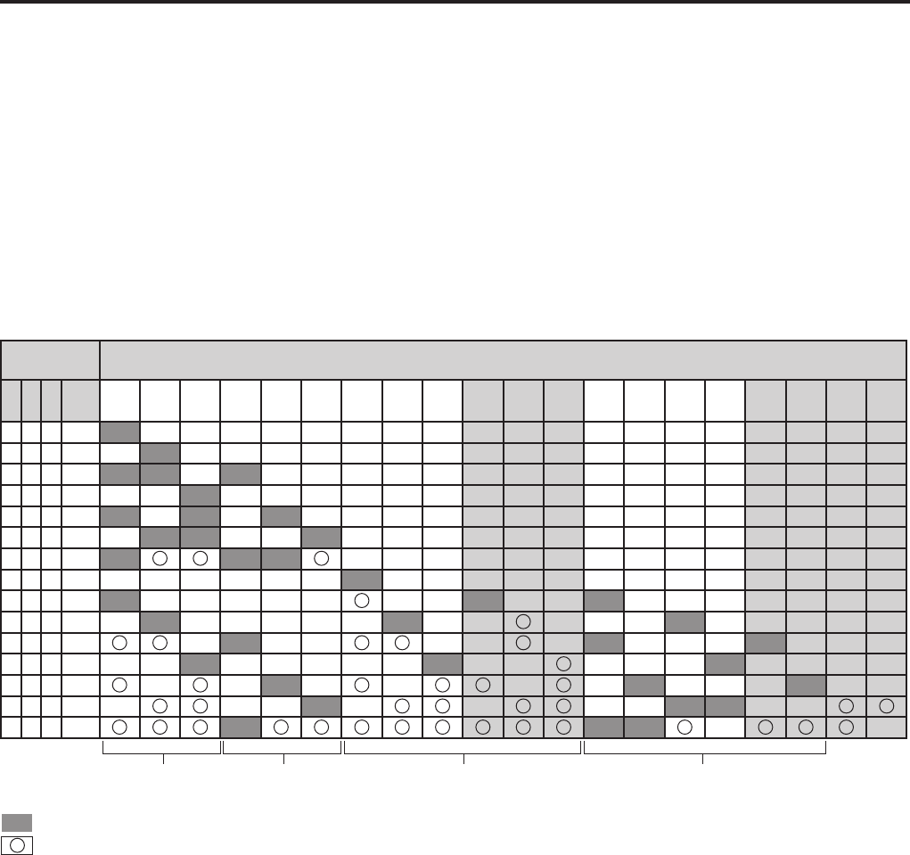
10 11
Camera Connection and Combination of Cameras
Camera
connection Combination of cameras
1 2 3 456 1, 1, 2, 3, 1, 1, 2, 3,
1 2 3 1,2 1,3 2,3
1456 2456 3456 1456P 2456P 3456P 2456 3456 3456 2456 2456P 3456P 3456P 2456P
0XXX1-------------------
X0XX-1------------------
0 0 X X 1 2 - 3 - - - - - - - - - - - - - - - -
XX0X--1-----------------
0 X 0 X 1 - 2 - 3 - - - - - - - - - - - - - - -
X 0 0 X - 1 2 - - 3 - - - - - - - - - - - - - -
0 0 0 X 1 2 3 - - - - - - - - - - - - - -
XXX0------1-------------
0 X X 0 1 - - - - - - - 2 - - 3 - - - - - - -
X 0 X 0 - 1 - - - - - 2 - - - - - 3 - - - - -
0 0 X 0 - 1 - - - - - 2 - - - 3 - - -
X X 0 0 - - 1 - - - - - 2 - - - - - 3 - - - -
0 X 0 0 - - 1 - - - - 2 - - - 3 - -
X 0 0 0 - - - 1 - - - - 2 3 - -
0 0 0 0 1 2 3 - -
1Ch 2Ch 4Ch
P: Panorama
: Preset number of recommended combination of cameras
: Selectable combination of cameras
0: A camera is connected.
X: A camera is not connected.
Combination of cameras depends on the cameras
connected to the recorder. Available combination is as
shown below.
Selectable combination of cameras depends on the
detected cameras.
If only CAM4, CAM5, and CAM6 are set to OFF, preset
patterns, 4Ch-QUAD, 4Ch-PANORAMA, 5Ch-QUAD, and
5Ch-PANORAMA, cannot be selected.
If all of CAM1, CAM2, and CAM 3 are set to OFF, preset
patterns, 4Ch-PANORAMA and 5Ch-PANORAMA, cannot
be selected.
If two channels of CAM1, CAM2, and CAM 3 are not
connected, preset patterns, 5Ch-PANORAMA cannot be
selected.
•
•
•
Selectable preset patterns depends on the detected
cameras.
If CAM1 is set to OFF, any combination of cameras
indicated by “1” cannot be selected.
If CAM2 is set to OFF, any combination of cameras
indicated by “2” cannot be selected.
If CAM3 is set to OFF, any combination of cameras
indicated by “3” cannot be selected.
If any of CAM4, CAM5, or CAM6 is set to ON, a pattern
indicated by “456” can be selected.
•
•
•
•
5Ch

1
1
Service Logs
The operation history of the recorder can be obtained as service logs.
Contents
The items shown below can be obtained as service logs.
Normal operation
Items Level Character strings Timing
Starting (start, restart) N Power On just after start
Ending (all power off, restart) N Power Off just before end
Starting (start, restart) N System Start AG-CPD20 4.xx.xxx.0
Serial No. Destination
just after start
Ending (all power off, restart) N System End just before end
Ending with power off I System End Acc when occurred
Restarting by restart operation I System End Reboot when occurred
Recording start N Rec File Start factor slot1
data/yyyymmdd/mmhhss.av
when occurred
Recording end N Rec Stop End factor when occurred
Restoring a file (succeeded) N Restore File slot1
data/yyyymmdd/mmhhss.av
when occurred
Deleting a file (succeeded) N Delete File slot1
data/yyyymmdd/mmhhss.av
when occurred
Formatting SD cards N Format when occurred
Deleting all files N DeleteAll when occurred
Application: transition to live
mode
I Mode Live when occurred
Application: transition to play
mode
I Mode Play when occurred
Application: transition to
administrator mode
I Mode Admin when occurred
Application: transition to
upload mode
I Mode Upload when occurred
Registering data from a USB
memory device
I Load Admin/Officer/…
number of cases
when occurred
Exporting start I Export Start when occurred
Exporting end I Export End when occurred
Uploading start I Upload Start when occurred
Uploading end I Upload End when occurred
Upgrading start I Vup Start New 4.xx.xxx.0 when occurred
Upgrading end I Vup End when occurred
Upgrading without menu
display start
I/N VupMenuless Start when occurred
Upgrading without menu
display end
I/N VupMenuless End when occurred
Menu exporting start I MenuExport Start when occurred
Menu exporting end I MenuExport End when occurred
Menu importing start (with or
without menu display)
I MenuImport Start when occurred
Menu importing end (with or
without menu display)
I MenuImport End when occurred

1
1
Items Level Character strings Timing
Initializing personal data I Clear Personal when occurred
Resetting to the factory default
settings
I Clear All when occurred
Resetting to the factory default
settings without menu display
N ClearMenuless All when occurred
Detecting the remote control
panel connection
I CP Attach 3.xx.xxx.x just after start
when occurred
Detecting the remote control
panel disconnection
I CP Dettach when occurred
Detecting the SD card slot door
open
N Slot Open just after start
when occurred
Detecting the SD card slot door
closed
I Slot Close just after start
when occurred
Recognizing SC cards in slots
1 to 4
I Card Slot1 PA-SV16G-C6
Total capacity, free capacity, serial No., etc.
(hexadecimal number of MID//PRV//PSN//MDT)
Card Slot2 NONE
Card Slot3 NONE
Card Slot4 NONE
just after start
when the SD card slot
door closed
Detecting a USB memory
device inserted
I USBMem Attach 0/1 just after start
when detected
Detecting a USB memory
device removed
I USBMem Dettach 0/1 when detected
Changing a USB memory
device status
I USB Front/Rear VendorID // ProductID //
manufacturer // product // serial
just after start
when occurred
Changing GPS status I GPS On just after start
when occurred
Changing GPS status I GPS Off just after start
when occurred
Adjusting the GPS time (other
than GPS)
I GPS Adjust when occurred
Radar gun connection status I Rader Detect model name First data reception
after start-up
Camera connection status
(1 to 6)
I Camera 1=On 2=Off 3=.. just after start
when occurred
Network connection status I Net PC=192.168.xx.xx
UPLOAD=NONE
WIRELESS=NONE
just after start
when occurred
Front-End and Back-End
application connection status
I PC FE=192.168.xx.xx
BE=NONE
when status changed
N (NOTICE): When a specified event is occurred
I (INFO): Debagging message
Service Logs (continued)
1
1
Error (displayed)
Items Level Character strings Timing
Record error E [Rec Error] error number
factor number
when occurred
SD card format error E [Format Error] error number when occurred
All deletion error E [DeleteAll Error] error number when occurred
Play error E [Play Error] error number when occurred
Export error E [Export Error] error number when occurred
Upload error E [Upload Error] error number when occurred
Upgrading error E [Vup Error] error number when occurred
Menu export error E [MenuExport Error] error number when occurred
Menu import error E [MenuImport Error] error number when occurred
Others E [Misc Error] error number when occurred
E (ERROR): When an error is generated
Error (not displayed)
Items Level Character strings Timing
Restoration error E Restore Error slot1
data/yyyymmdd/mmhhss.av
when occurred
Deletion error E Delete Error slot1
data/yyyymmdd/mmhhss.av
when occurred
Upgrading error without menu
display
E VupMenuless Error "factor number" when occurred
E (ERROR): When an error is generated
Service Logs (continued)

1
1
Format of Service Log
The format of the service log is as shown below.
<TS>UTC 2008-11-22 00:48:09</TS><LV>N</LV><OP>Power On</OP>
<TS>2008-11-22 09:48:12</TS><LV>N</LV><OP>System Start AG-CPD20 4.xx.xxx.0 ABCD123456 usa</
OP>
<TS>2008-11-22 09:48:23</TS><LV>N</LV><OP>Slot Close</OP>
<TS>2008-11-22 09:48:27</TS><LV>N</LV><OP>Card Slot1 PA-SV16G-C6 15814656 15814560
1//88//2080763F//7B
</OP>
<TS>2008-11-22 09:48:27</TS><LV>N</LV><OP>Card Slot2 NONE</OP>
<TS>2008-11-22 09:48:27</TS><LV>N</LV><OP>Card Slot3 NONE</OP>
<TS>2008-11-22 09:48:27</TS><LV>N</LV><OP>Card Slot4 NONE</OP>
<TS>2008-11-22 10:23:45</TS><LV>N</LV><OP>Rec File GPIO1 slot1 data/20081122/102345.av</OP>
<TS>2008-11-22 11:07:32</TS><LV>N</LV><OP>Rec Stop STOP</OP>
<TS>2008-11-22 12:13:30</TS><LV>N</LV><OP>System End Acc</OP>
<TS>2008-11-22 12:13:35</TS><LV>N</LV><OP>System End</OP>
<TS>2008-11-22 12:13:37</TS><LV>N</LV><OP>Power Off</OP>
<TS> (Time Stamp): The local time is automatically added upon obtaining other user log. However, the times for
the Power On log, upgrading without displaying menu during start-up, and initializing to the
factory default settings during start-up are the UTC times.
Service Logs (continued)

1
This product is licensed under the AVC Patent Portfolio
License for the personal and noncommercial use of a
consumer, and no license is granted or shall be implied
for any use other than the personal uses detailed
below.
- To encode video in compliance with the AVC standard
("AVC Video")
- To decode AVC Video that was encoded by a consumer
engaged in a personal and noncommercial activity
- To decode AVC Video that was obtained from a video
provider licensed to provide AVC Video
Additional information may be obtained from MPEG LA,
LLC (http://www.mpegla.com).
- Separate license contracts must be obtained from
MPEG LA where SD Memory Cards containing
information recorded with this product are to be
distributed to end users for commercial purposes.
"End user" refers to persons or organizations handling
such contents for personal use.
This product is licensed under the MPEG-4 Visual
patent portfolio license for the personal and
noncommercial use of a consumer for (i) encoding
video in compliance with the MPEG-4 Visual Standard
("MPEG-4 Video") and/or (ii) decoding MPEG-4
Video that was encoded by a consumer engaged in
a personal and non-commercial activity and/or was
obtained from a video provider licensed by MPEG LA to
provide MPEG-4 Video. No license is granted or shall
be implied for any other use. Additional information
including that relating to promotional, internal and
commercial uses and licensing may be obtained from
MPEG LA, LLC.
See http://www.mpegla.com/
Portions utilize Microsoft Windows Media Technologies.
Copyright (c)2006 Microsoft Corporation. All Rights
Reserved.
Included with this product is software licensed under
the MIT License.
Copyright (c) 1998, 1999, 2000 Thai Open Source
Software Center Ltd
and Clark Cooper
Copyright (c) 2001, 2002, 2003, 2004, 2005, 2006
Expat maintainers.
Permission is hereby granted, free of charge, to
any person obtaining a copy of this software and
associated documentation les (the "Software"), to
deal in the Software without restriction, including
without limitation the rights to use, copy, modify, merge,
publish, distribute, sublicense, and/or sell copies of the
Software, and to permit persons to whom the Software
is furnished to do so, subject to the following conditions:
The above copyright notice and this permission notice
shall be included in all copies or substantial portions of
the Software.
THE SOFTWARE IS PROVIDED "AS IS", WITHOUT
WARRANTY OF ANY KIND, EXPRESS OR
IMPLIED, INCLUDING BUT NOT LIMITED TO
THE WARRANTIES OF MERCHANTABILITY,
FITNESS FOR A PARTICULAR PURPOSE AND
NONINFRINGEMENT. IN NO EVENT SHALL THE
AUTHORS OR COPYRIGHT HOLDERS BE LIABLE
FOR ANY CLAIM, DAMAGES OR OTHER LIABILITY,
WHETHER IN AN ACTION OF CONTRACT, TORT
OR OTHERWISE, ARISING FROM, OUT OF OR IN
CONNECTION WITH THE SOFTWARE OR THE USE
OR OTHER DEALINGS IN THE SOFTWARE.
Software License Agreement

Panasonic Computer Solutions Company
50 Meadowlands Parkway, Panazip 2F-5,
Secaucus, NJ 07094
© 2009 P
