Panasonic Wv Ase201 Operating Instructions
2015-05-18
: Panasonic Panasonic-Wv-Ase201-Operating-Instructions-731294 panasonic-wv-ase201-operating-instructions-731294 panasonic pdf
Open the PDF directly: View PDF ![]() .
.
Page Count: 137 [warning: Documents this large are best viewed by clicking the View PDF Link!]
- Preface
- Operation flow
- Start/exit the operation software
- User management
- Operation window
- Outline of the multi-monitor function
- Monitor live images
- Switch the pattern of the screen
- Operate using the multi-monitor function
- Operate the cameras
- Operation of SD memory card
- Playback
- Play images using the "Quick playback" panel
- Start/stop recording manually
- Search
- Play from the search results
- Search face
- Check the alarm notification
- Search the alarm notification
- Register a face for the alarm notification
- Display the statistical graphics of age/gender/head-count
- Change the display setting (Hide the display)
- Save recorded images
- Display/edit text information
- Convert a file to the standard format
- Control a decoder
- Viewer software
- Alarm/event notification and management of logs
- Troubleshooting
- Displayed messages and solutions
- Operation using the system controller

Before attempting to connect or operate this product,
please read these instructions carefully and save this manual for future use.
The model number is abbreviated in some descriptions in this manual.
Operating Instructions
PC Software Package
Model No. WV-ASM200
WV-ASM200W
Extension Software
Model No. WV-ASE201, WV-ASE202
WV-ASE203, WV-ASE204
WV-ASE231
WV-ASE201W, WV-ASE202W
WV-ASE203W, WV-ASE204W

2
3
CONTENTS
Preface ...................................................................... 3
Software configuration .......................................... 3
System configuration ............................................ 3
System specifications ........................................... 4
Compatible devices ............................................... 5
Features................................................................. 6
Standard accessories ............................................ 7
About the user manuals ........................................ 7
Trademarks and registered trademarks ................ 8
About use of open source software ...................... 8
Abbreviations ........................................................ 9
Document convention ......................................... 10
Restrictions when operating MPEG-4 or H.264
images ................................................................. 12
Operation flow ......................................................... 14
Start/exit the operation software ............................. 15
Start the operation software ................................ 15
Exit the operation software ................................. 17
User management ................................................... 18
About the user level setting ................................. 18
Password’s validation period .............................. 19
User switch .......................................................... 20
Operation window ................................................... 21
Function panel ..................................................... 26
Layout of the operation window .......................... 27
Pop-up menu ...................................................... 28
Information display area ...................................... 29
Camera operation panel ...................................... 29
Playback operation panel .................................... 32
SD operation panel .............................................. 34
Search window .................................................... 35
Alarm/event notification message ....................... 37
License registration message .............................. 38
Outline of the multi-monitor function ...................... 39
Live window ........................................................ 40
Map window ........................................................ 43
About the "Face Search" window ....................... 44
Monitor live images ................................................. 45
Confirm the registered devices ........................... 45
Monitor images from the selected camera ......... 49
Display images from the cameras registered as a
group (group display) .......................................... 52
Display images from the cameras registered as a
group sequentially (sequence display) ................ 53
Switch the pattern of the screen ............................. 55
Switch the screen pattern from 16-screen .......... 55
Operate using the multi-monitor function ............... 59
Operate the operation window ............................ 59
Operate the live window ...................................... 60
Operate the map window .................................... 60
Operate the cameras ............................................... 63
Operation of SD memory card ................................ 64
Download recorded images ................................ 64
Playback .................................................................. 67
Play images using the "Quick playback" panel ....... 69
Start/stop recording manually ................................. 71
Search ..................................................................... 72
Search recording event ....................................... 72
Search for times and dates of motion-containing
images ................................................................. 74
Play from the search results .................................... 76
Play recorded images from the
search result list .................................................. 76
Play recorded images using the
"Search" panel .................................................... 77
Search face ............................................................. 78
Search by time and date ..................................... 78
Search by face .................................................... 79
Play recorded image in search result .................. 81
Check the alarm notification ................................... 83
Display the "Alarm notification" window ............. 83
Play images recorded by the alarm recording .... 84
Search the alarm notification .................................. 85
Search by time and date ..................................... 85
Search by person (face) ...................................... 86
Play recorded image in search result .................. 87
Register a face for the alarm notification ............... 89
Register from a face thumbnail image ................ 89
Register from recorded images ........................... 90
Register from snapshot ....................................... 91
Display the statistical graphics of age/gender/
head-count .............................................................. 92
Display the statistical results ............................... 92
Download the statistics results as a CSV file ...... 93
Change the display setting (Hide the display) ......... 94
Display the border frame for face
(Hide the border frame) ...................................... 94
Save recorded images ............................................. 95
Download recorded images ................................ 95
Save as a JPEG file ............................................. 99
Print ....................................................................... 100
Display/edit text information ................................. 101
Convert a file to the standard format .................... 102
Control a decoder ................................................. 104
Control a decoder ............................................. 104
Viewer software ..................................................... 107
Install the viewer software ................................. 107
Uninstall the viewer software ............................ 108
How to use the viewer software (ND_Viewer) ... 108
Alarm/event notification and
management of logs .............................................. 112
Alarm/event notification window ....................... 112
"Alarm notification" window .............................. 113
Alarm mode of the live window ......................... 115
"Alarm log" panel .............................................. 120
"Device error log" panel .................................... 121
"Network error log" panel .................................. 122
Troubleshooting ..................................................... 123
Displayed messages and solutions ....................... 130
Operation using the system controller .................. 134
2
3
Preface
The PC Software Package WV-ASM200 (hereinafter this software) is designed for integrated management of
multiple Panasonic network disk recorders and digital disk recorders (hereinafter recorders), network interface
unit (hereinafter encoders) and network cameras (hereinafter cameras) connected to a network such as a LAN
or the Internet, and runs on the Microsoft® Windows® operating system.
Refer to the "Compatible devices" section (+ page 5) for the devices compatible with this software.
By using this software on a personal computer (hereinafter PC) via a network, it is possible to display live
images of the cameras, to play images stored on the recorder, and to download image files to the hard disk
drive of the PC.
Software configuration
This software consists of the following 3 applications:
Setup software: The settings required to run the operation software can be configured
and managed with this software.
Operation software: Displaying live images, playback, downloading, searching for images
stored on the recorder, and controlling of the camera is available using
this software.
Service software: Reception of Panasonic alarm protocol and auto deletion of the operation
log will be carried out by this software.
This is the resident application (in the system tray). Once the PC is turned
on, the service software runs in the background of the PC.
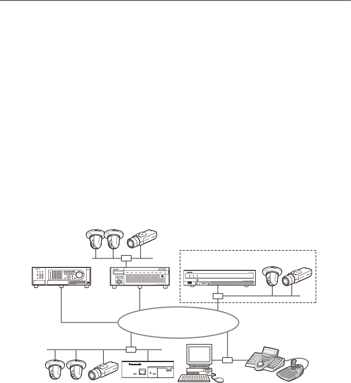
System configuration
PC in which the
software is installed
System controller†2
Network disk
recorder
Network disk
recorder
Digital disk
recorder
Network Video Encoder
Network
Network camera
Network camera
†1
Network camera
Network Video Encoder
WJ-GXE500
Digital Disk Recorder WJ-HD616

4
5
†1: When the system is configured as "System A" in the illustration above, live images from the cameras con-
nected to the recorder can directly be monitored with this software, not through the recorder.
To monitor live images directly from the cameras with this software, the following are necessary.
Register cameras in the recorder. •
The recorder should be used with a single port.•
†2: The system controller is optional.
Important:
Do not use cross cables to connect the PC and each device.•
When connecting multiple system controllers, operation of this software is not guaranteed.•
System specifications
•Recorderregistration: Upto100recorders
•Encoderregistration: Upto64encoders
•Cameraregistration: Upto256cameras
•Decoderregistration: Upto10decoders(ThelicensefortheWV-ASE204isrequired.)
•Userregistration: Upto32users
•Userlevels: 5levels
•Groupregistration: Upto400groups
•Sequenceregistration: Upto10sequences(Upto64stepscanberegisteredforasequence)
•Mapregistration: Upto100maps(Upto64camerascanbeassignedonamap,upto20
registered maps can be used.) (The file size shall be less than 10 MB.
Available file type is JPEG and BMP.)
•Numberofthealarmlogsthatcanbestored: Upto30000logs(Upto1000logscanbedisplayed)
•Numberofthedeviceerrorlogsthatcanbestored: Upto1000logs(Upto1000logscanbedisplayed)
•Numberofthenetworkerrorlogsthatcanbestored: Upto1000logs(Upto1000logscanbedisplayed)
•Numberofthesystemlogsthatcanbestored: Upto1000logs(Upto1000logscanbedisplayed)
•Numberoftheoperationlogsthatcanbestored: Upto100000logs(Upto1000logscanbedisplayed)
•Numberofsearchresultsthatcanbedisplayed: Upto1000logs search results (Up to 200 results for
VMD search)
Note:
Number of PCs that can concurrently access a single recorder differs depending on choosing whether or •
not to use "Live window" and the model of the recorder in use.
Recorder Use of "Live window"
Yes No
ND300 4 6
ND200 2 4
HD300†3 2†1 3†2
ND400 8 16
HD600 4 8
NV200 1 1
ASR500 †4 †4
†1: When displaying images on a 16-screen or
9-screen, only a single PC can access.
†2: When displaying images on a 16-screen, 2 PCs
can access.
†3: Under the following conditions, connection to the
recorder may be interrupted and a black screen
may be displayed.
Event recording and sequence are being oper-•
ated.
The total live rate for each HD300 is 15 ips or •
more
Refer to "WV-ASM200 Setup Instructions" for
how to configure the settings for the live rate
for HD300.
†4: Note that it varies depending on the system con-
figuration in use.
When exceeding the maximum number of concurrent access due to an increase in the number of accesses •
using web browsers or FTP accesses, connection to the recorder may be interrupted and a black screen
may be displayed.
By adding the license for the Extension Software WV-ASE203 (option), it will become possible to expand the •
maximum numbers of registered recorders, encoders and cameras to 100, 64 and 256 respectively. Up to 4
licenses for the WV-ASE203 can be added.

4
5
Compatible devices
The following devices are compatible with this software.
Important:
Some functions may not work depending on the firmware version of the compatible device. •
Refer to the Panasonic support website (http://security.panasonic.com/pss/security/support/index.html) for
further information.
Note:
Refer to the operating instructions of the recorder in use for the cameras that can be connected to the re-•
corder in use.
Compatible recorders
Model Appears in this document as Version Compression
ND300 series ND300 5.20 or later MPEG-4
M-JPEG
H.264
ND200 series ND200 3.30 or later MPEG-4
M-JPEG
H.264
HD300 series HD300 3.44 or later Model-specific
ND400 series ND400 2.20 or later MPEG-4
M-JPEG
H.264
HD600 series HD600 2.06 or later H.264
NV200 series NV200 1.04 or later MPEG-4
M-JPEG
H.264
ASR500 series ASR500 5.9.1901.48362
or later
MPEG-4
M-JPEG
H.264
Compatible encoder
Model Appears in this document as Version Compression
WJ-NT304 NT304 1.32 or later MPEG-4
M-JPEG
WJ-NT314 NT314 1.32 or later MPEG-4
M-JPEG
WJ-GXE500 GXE500 1.30 or later H.264
MPEG-4
M-JPEG
WJ-GXE100 GXE100 1.72 or later H.264
M-JPEG
Compatible cameras
Refer to the Readme.txt on the provided CD-ROM.
Compatible decoder (The license for the WV-ASE204 is required.)
Model Appears in this document as Version Compression
WJ-GXD400 GXD400 2.20 or later H.264
MPEG-4
M-JPEG

6
7
Features
Important:
To use the following functions, it is necessary to add the license for the Extension Software WV-ASE201 •
(option).
Live window•
Map window•
Control using the System Controller WV-CU950•
Refer to the WV-ASM200 Setup Instructions (PDF) for further information about how to add the license for
the Extension Software.
To control the GXD400, it is necessary to register the license for the Extension Software WV-ASE204 (op-•
tion) additionally.
To use the following functions, it is necessary to add the license for the Extension Software WV-ASE• 231
(option).
Face search monitor•
Remote operation of devices
It is possible to operate the recorder, encoder and cameras via a network using this software. When operating
the recorder via a network, displaying live images, playback of recorded images, camera operation, status indi-
cation, searching, etc. are available.
Refer to the following chapters for further information.
"Status bar" (+ page 23)
"Monitor live images" (+ page 45)
"Operate the cameras" (+ page 63)
"Playback" (+ page 67)
"Search" (+ page 72)
Multi-monitor function
The multi-monitor function using up to four PC monitors is available, and it makes possible to display the oper-
ation window, the live window and the map window simultaneously.
Refer to the "Operate using the multi-monitor function" (+ page 59) for further information.
To use the multi-monitor function, it is necessary to add the license for the Extension Software WV-ASE201.
Image download
It is possible to download recorded images by designating the time range and the target recorders or cameras.
Refer to the "Download recorded images" section (+ page 64) for further information.
Alarm/event notification and management of logs
Alarm notification:• The alarm description will be displayed in a pop-up window (alarm notification window)
on the operation window when an alarm occurrence is notified from the recorder. The alarm description will
also be displayed as a log in the alarm log panel.
Event notification:• The error description will be displayed in a pop-up window (error notification window)
on the operation window upon a recorder error occurrence or upon a network error occurrence. The error
description will also be displayed as a log in the device error log panel or in the network error log panel.
Management of logs:• Each time an alarm or an error occurred, a log will be filed automatically. Logs can
be checked in the log panels (alarm log panel, device error log panel and network error log panel) by log
type (alarm log, device error log and network error log) respectively.
When a log displayed in the log panel is clicked, playback of the respective recorded images will start.
Refer to the "Alarm/event notification and management of logs" section (+ page 112) for further information
about the management of logs.

6
7
Security
It is possible to enhance security by using the user authentication function (requires entering a user name and
password). This software manages the administrator (who can administrate this software) and the registered
users (who can operate this software except configurations).
It is also possible to restrict operable functions by applying the user level to each registered user.
Refer to the "User management" section (+ page 18) for further information about the user management.
Important:
Check if the model in use is compatible with each function. •
Refer to the Panasonic support website (http://security.panasonic.com/pss/security/support/index.html) for
further information.
Standard accessories
CD-ROM .......................................................... 1 pc.
Installation guide ............................................. 1 pc.
Activation Key Card ......................................... 1 pc.
Important:
The provided CD-ROM contains the installer of this software, the operating instructions (PDF), the setup in-•
structions (PDF) and the Readme.txt.
Prior to installation, read the Readme.txt.
This software will not work if the license is not registered. After installing the software on the PC in use, reg-•
ister the license.
About the user manuals
There are two PDF manuals (the operating instructions and the setup instructions) and the installation guide
(leaflet).
This PDF manual contains descriptions for the registered users such as descriptions about the functions of the
operation software and of how to operate the operation window.
Refer to the WV-ASM200 Setup Instructions (PDF) for descriptions of how to install this software and about the
required preliminary settings before starting running this software.
"WV-ASE201" shown in the instructions and illustrations used in this manual indicates the WV-ASE201,
WV-ASE201W.
"WV-ASE202" shown in the instructions and illustrations used in this manual indicates the WV-ASE202,
WV-ASE202W.
"WV-ASE203" shown in the instructions and illustrations used in this manual indicates the WV-ASE203,
WV-ASE203W.
"WV-ASE204" shown in the instructions and illustrations used in this manual indicates the WV-ASE204,
WV-ASE204W.
The descriptions in the following pages are based on the assumption that Microsoft® Windows® 7 Professional
runs on a PC.
Operation windows may not be the same as those appearing on the pages when a different OS is used or dif-
ferent settings are applied.
When using other OS, refer to the operating instructions of the respective OS.

8
9
Trademarks and registered trademarks
Adobe, Acrobat Reader and Reader are either registered trademarks or trademarks of Adobe Systems •
Incorporated in the United States and/or other countries.
Microsoft, Windows, Windows Vista, Internet Explorer, Active X and DirectX are either registered trademarks •
or trademarks of Microsoft Corporation in the United States and/or other countries.
Microsoft product screen shot(s) reprinted with permission from Microsoft Corporation.•
Intel and Intel Core are trademarks or registered trademarks of Intel Corporation in the United States and •
other countries.
All other trademarks identified herein are the property of their respective owners.•
About use of open source software
This product uses open source software.
Software name Copyright License name
OpenCV Intel Corporation
Willow Garage Inc
License Agreement For Open Source
Computer Vision Library (BSD License)
Dynamic Json neuecc <ils@neue.cc> Ms-PL
Extended WPF Toolkit Xceed Software Inc. Ms-PL
The following are the entire text of the license agreements to be applied.
License Agreement For Open Source Computer Vision Library (BSD License)
IMPORTANT: READ BEFORE DOWNLOADING, COPYING, INSTALLING OR USING.
By downloading, copying, installing or using the software you agree to this license.
If you do not agree to this license, do not download, install, copy or use the software.
License Agreement
For Open Source Computer Vision Library
Copyright© 2000-2008, Intel Corporation, all rights reserved.
Copyright© 2008-2010, Willow Garage Inc., all rights reserved.
Third party copyrights are property of their respective owners.
Redistribution and use in source and binary forms, with or without modification, are permitted provided that the
following conditions are met:
* Redistribution's of source code must retain the above copyright notice, this list of conditions and the following
disclaimer.
* Redistribution's in binary form must reproduce the above copyright notice, this list of conditions and the fol-
lowing disclaimer in the documentation and/or other materials provided with the distribution.
* The name of the copyright holders may not be used to endorse or promote products derived from this soft-
ware without specific prior written permission.
This software is provided by the copyright holders and contributors "as is" and any express or implied warran-
ties, including, but not limited to, the implied warranties of merchantability and fitness for a particular purpose
are disclaimed.

8
9
In no event shall the Intel Corporation or contributors be liable for any direct, indirect, incidental, special, exem-
plary, or consequential damages (including, but not limited to, procurement of substitute goods or services;
loss of use, data, or profits; or business interruption) however caused and on any theory of liability, whether in
contract, strict liability, or tort (including negligence or otherwise) arising in any way out of the use of this soft-
ware, even if advised of the possibility of such damage.
Microsoft Public License (Ms-PL)
This license governs use of the accompanying software. If you use the software, you accept this license. If you
do not accept the license, do not use the software.
1. Definitions
The terms "reproduce," "reproduction," "derivative works," and "distribution" have the same meaning here as
under U.S. copyright law.
A "contribution" is the original software, or any additions or changes to the software.
A "contributor" is any person that distributes its contribution under this license.
"Licensed patents" are a contributor's patent claims that read directly on its contribution.
2. Grant of Rights
Copyright Grant- Subject to the terms of this license, including the license conditions and limitations in section
3, each contributor grants you a non-exclusive, worldwide, royalty-free copyright license to reproduce its con-
tribution, prepare derivative works of its contribution, and distribute its contribution or any derivative works that
you create.
Patent Grant- Subject to the terms of this license, including the license conditions and limitations in section 3,
each contributor grants you a non-exclusive, worldwide, royalty-free license under its licensed patents to make,
have made, use, sell, offer for sale, import, and/or otherwise dispose of its contribution in the software or deriv-
ative works of the contribution in the software.
3. Conditions and Limitations
(A) No Trademark License- This license does not grant you rights to use any contributors' name, logo, or trade-
marks.
(B) If you bring a patent claim against any contributor over patents that you claim are infringed by the software,
your patent license from such contributor to the software ends automatically.
(C) If you distribute any portion of the software, you must retain all copyright, patent, trademark, and attribution
notices that are present in the software.
(D) If you distribute any portion of the software in source code form, you may do so only under this license by
including a complete copy of this license with your distribution. If you distribute any portion of the software
in compiled or object code form, you may only do so under a license that complies with this license.
(E) The software is licensed "as-is." You bear the risk of using it. The contributors give no express warranties,
guarantees or conditions. You may have additional consumer rights under your local laws which this license
cannot change. To the extent permitted under your local laws, the contributors exclude the implied warran-
ties of merchantability, fitness for a particular purpose and non-infringement.
Abbreviations
These are descriptions of the basic terms used in these operating instructions.
Microsoft• ® Windows Vista® Business SP2 (32-bit) and Microsoft® Windows Vista® Business SP2 (64-bit) are
described as Windows Vista.
Microsoft• ® Windows® 7 Professional SP1 (32-bit) and Microsoft® Windows® 7 Professional SP1 (64-bit) are
described as Windows 7.
Microsoft® Windows• ® 8 Pro (32-bit) and Microsoft® Windows® 8 Pro (64-bit) are described as Windows 8.

10
11
Administrator
Indicates a person responsible for management and
operation of this software.
User
Indicates a person who operates this software. Each
user should be defined as an administrator or a regis-
tered user in this software. Only a user who is regis-
tered as an administrator can configure and maintain
this software.
Recorder
Indicates Panasonic network disk recorders or digital
disk recorders.
Refer to the "Compatible devices" section (+ page 5)
for the devices compatible with this software.
Encoder
Indicates Panasonic network interface unit.
Refer to the "Compatible devices" section (+ page 5)
for the devices compatible with this software.
Fixed camera
Indicates cameras without the panning and tilting
functions.
PTZ camera
Indicates cameras featuring the panning, tilting and
zooming functions.
Fisheye camera
Indicates Panasonic Fisheye network cameras.
Live image
Indicates live images from the camera.
Decoder
Indicates Panasonic network video decoders. Refer
to the "Compatible devices" section (☞ page 5) for
the devices compatible with this software.
Direct image reception
Indicates that image reception directly from a camera
registered in the network disk recorder, not through
the recorder.
Group display
Images from cameras can be registered as a group
and displayed by groups.
Sequence
Images of each registered group can be displayed
sequentially in the order determined in advance.
The sequence function of this software is available
only for live image display.
EL-zoom
Indicates the zoom function available when displaying
live or recorded images.
While the zoom function of the camera enlarges
images using the zoom lens of the camera, the
EL-zoom function enlarges images by processing
images on this software.
Clicking a point in the EL-zoomed image moves the
displayed EL-zoomed image by positioning the
clicked point as the center point.
Camera operation
Indicates the operations of the camera connected,
such as panning/tilting, zooming, focusing, starting
the preset function (move to the preset position),
starting the selected auto mode function, brightness
adjustment, preset registration and AUX control.
Network playback
Recorded images on the recorder can be played via a
network.
Manual recording
Indicates recording that is performed by clicking the
[REC START] button and the [REC STOP] button.
Download
Indicates file (recorded image on the recorder) trans-
fer from the recorder to a PC using the FTP function.
Image file
Indicates downloaded recorded image from the
recorder.
File playback
Indicates playback of image files using the viewer
software.
Notification function using the Panasonic
alarm protocol
Indicates the function that uses alarm/event notifica-
tion transmitted from the device using Panasonic
alarm protocol.
Document convention
These are descriptions of the basic terms used in these operating instructions.

10
11
Application log
Indicates logs filed each time when this software
obtains information about an alarm or a device error
occurrence from the recorder, or when an operation
of this software is made, etc.
The application logs are filed as distinct logs; alarm
log, device error log, network error log, system log
and operation log.
Recorder log
Indicates logs filed each time when a recorder error
or a network error occurred in the recorder.
The recorder logs are generated in the recorder.
The recorder logs are filed as distinct logs; error log,
access log, event log and network log.
M-JPEG
Indicates a video codec that compresses video fields
from the camera into independent JPEG images
sequentially.
Network load will be reduced comparing with the
method that obtains JPEG images independently
from the camera. However, the transmission rate will
fluctuate depending on the state of the camera.
Some cameras phrase this video codec as just
"JPEG".
REC event
Indicates the reason (an event or an operation) why
the recording started.
The recording event will be described as follows.
Manual, schedule, emergency, site alarm, terminal
alarm, command alarm, VMD, video loss, SD memory
backup
SD memory recording (SD memory data)
Indicates the function featured in some Panasonic’s
cameras that transfers images saved on the SD mem-
ory card on the camera to the recorder.
Recorded images transferred to the recorder are
described as "SD memory data" in these operating
instructions.
The recording time of SD memory data will be dis-
played based on the clock of the camera.
Setup software
Indicates the application used to configure the set-
tings required to run the operation software.
Operation software
Indicates the application used for displaying live
images of the recorders, encoders and cameras,
playback, downloading, searching for images stored
on the recorder, and controlling the camera.
Operation window
Indicates the window used to operate all functions
except for configurations of this software.
Live window
Indicates the window used only for the group or
sequence display of live images.
Map window
Indicates the window that displays a map with the
registered camera icons.
It is possible to display live images from the desired
camera by clicking the respective camera icon on the
map.
SD memory download
Indicates the function featured in some Panasonic’s
cameras that transfers H.264 video files (mp4 files)
saved on the SD memory card equipped with the
camera to a PC using the FTP function.
Smooth & fast playback mode
Indicates the mode that can play back all the frames
without skipping when playing back Step 2 and
Step 3.
License
Registration is surely required before using this soft-
ware. Refer to the provided "Activation Key Card" to
obtain and register the "Registration Key". The
obtained "Registration Key" can be used only on the
PC in which the software is installed.
Demo edition
It is possible to use all the functions of the designated
software for 90 days by registering the license for the
demo edition.
Face search monitor
This window is used to perform operation relating to
the face search. The real time alarm display, face/
alarm search and age/gender report will be executed
on this window.

12
13
Restrictions when operating MPEG-4 or H.264 images
There are following restrictions for each function when MPEG-4 or H.264 images are used with this software.
Read the following before operating this software.
1. When displaying live images
Black screen may be displayed for the first few seconds (*) when the following operations are performed •
while displaying live images in MPEG-4 or H. 264 format.
When trying to display live images in MPEG-4 or H. 264 format. (By switching camera channel, etc.)•
When MPEG-4 or H.264 image is enlarged•
Example: When "3 seconds" is selected for the refresh interval on the camera, MPEG-4 or H.264 images will
be refreshed in 3 seconds intervals.
When displaying SXVGA images• , live images will be displayed with the following interval.
When images are obtained from a recorder, encoder or camera • other than ASR500, images on 16-/25-/
36-/49-/64-screen will be displayed with the refresh interval (*). (All images will be kept displayed for sev-
eral seconds from the moment when the images are displayed.)
When images are obtained from ASR500• , images on 1-screen will be refreshed with the live rate speci-
fied on the recorder. Images being displayed on 4-/9-/16-/25-/36-/49-/64-screen will be refreshed at 1
second interval. When displaying images on a multi-screen, image refresh delay of 5 seconds or less
may sometimes occur.
When displaying FULL HD images, live images will be displayed with the following interval.•
When images are obtained from a recorder, encoder or camera other than ASR500, images on •
4-/9-/16-/25-/36-/49-/64-screen will be displayed with the refresh interval (*). (All images will be kept dis-
played for several seconds from the moment when the images are displayed.)
When images are obtained from ASR500, images on • 1-screen will be refreshed with the live rate specified
on the recorder.
Images on 4-/9-/16-/25-/36-/49-/64-screen will be refreshed at 1 second interval. When displaying images
on a multi-screen, image refresh delay of 5 seconds or less may sometimes occur.
2. When playing recorded images
Displayed playback time may be fast for several seconds (*) when the following operations are performed •
while playing recorded MPEG-4 or H. 264 images.
When trying to display playback images in MPEG-4 or H. 264 format. (By switching camera channel, •
etc.)
When MPEG-4 or H.264 image is enlarged •
(When operating to enlarge a paused recorded MPEG-4 image, image of several seconds later than the
paused image may be enlarged.)
When the [PLAY] button is clicked again while playing MPEG-4 or H.264 images•
Playback may be performed in several seconds intervals (*) when the following operations are performed •
while playing MPEG-4 or H.264 images.
•Reverseplayback
•Fastplayback/Fastreverseplayback
•Reverseframeplayback
Example: When "3 seconds" is selected for the refresh interval on the camera, MPEG-4 or H.264 images will
be played in 3 seconds intervals.
When two records are played sequentially, the last few frames of the former record and the first few frames •
of the next record may be displayed overlapped.
When the [SKIP] button or the [REV SKIP] button is clicked, a skipped point may be a few seconds later (†) •
from a point to be skipped with the selected amount of time or from the first frame of the next record.
Sometimes, playback may start from the beginning of the next record.
When a black screen is being displayed, the following operations are inoperable.•
•Playback/Reverseplayback

12
13
•Fastplayback/Fastreverseplayback
•Frameplayback/Reverseframeplayback
•Skippingtothenext/previousrecordedimage
•Skippingtothepointofthesetamountoftimeforward/backward
•Pause
When playing images by designating time & date, playback may start from a point several seconds (†) after •
the designated time & date. Sometimes, playback may start from the beginning of the next record.
When displaying SXVGA images• , recorded images will be displayed with the following interval.
When images are obtained from a recorder, encoder or camera • other than ASR500, images on
16-/25-/36-/49-/64-screen will be displayed with the refresh interval (*). (All images will be kept displayed
for several seconds from the moment when the images are displayed.)
When images are obtained from ASR500• , images on 1-screen will be refreshed with the live rate speci-
fied on the recorder. Images being displayed on 4-/9-/16-/25-/36-/49-/64-screen will be refreshed at 1
second interval. When displaying images on a multi-screen, image refresh delay of 5 seconds or less
may sometimes occur.
When displaying FULL HD images, recorded images will be displayed with the following interval.•
When images are obtained from a recorder, encoder or camera other than ASR500, images on •
4-/9-/16-/25-/36-/49-/64-screen will be displayed with the refresh interval (*). (All images will be kept dis-
played for several seconds from the moment when the images are displayed.)
When images are obtained from ASR500, images on • 1-screen will be refreshed with the recording rate
specified on the recorder.
Images on 4-/9-/16-/25-/36-/49-/64-screen will be refreshed at 1 second interval. When displaying
images on a multi-screen, image refresh delay of 5 seconds or less may sometimes occur.
3. When downloading recorded images
Download of recorded images may start from a point several seconds (†) after the designated start time.
Set the time range for download longer than the refresh interval set on the camera.
Important:
Time (seconds) and intervals with an asterisk (†) differ depending on the refresh interval set on the camera. •
(Valid entry range: Differs depending on the model number of the camera.)
To shorten time lag, set the refresh interval on the camera shorter. •
Refer to the operating instructions of the camera for how to configure the refresh interval.
14
15
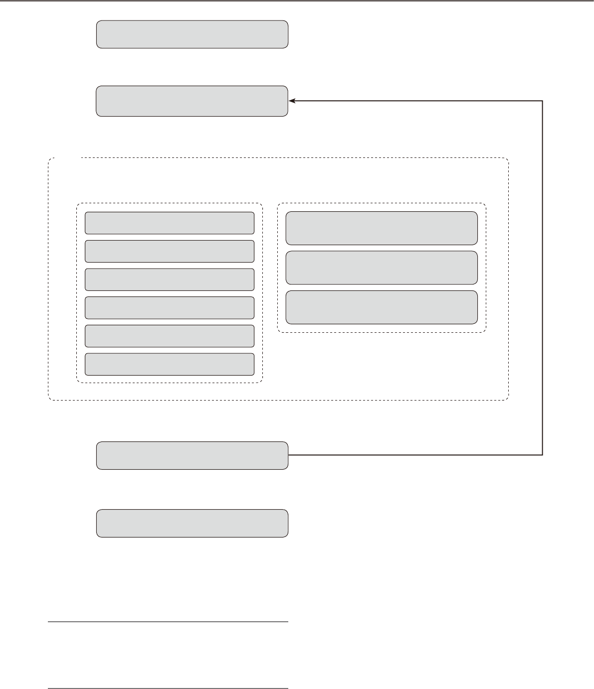
Operation flow
Startup of the operation software z Refer to the "Start/exit the operation software"
section (☞ page 15) for how to start the operation
software.
x Log in to the software.
➜ ➜
Login
† For frequent users, it is unnecessary to log in at
startup of the software when using the auto login
function.
Only an administrator can configure the settings
for the auto login function.
Note:
When a message window is displayed by clicking •
the button on the window, refer to the "Displayed
messages and solutions" section (☞ page 130)
and follow the instructions.
z
x
Monitoring of live images
Searching for recorded images
Playback of recorded images
Saving of recorded images
Printing of images
Alarm/error notification
➜ ➜
Live window
Map window
Face search monitor
Logout
Exit the operation software
c The operation window will be displayed.
Searching, playback and saving of the displayed
image are available using the menu panel and the
tool bar.
Refer to the "Operation window" section (☞ page
21) for further information.
v Log out of the software when finishing operation.
It is possible to log in to the software again using
another user name (user switch).
Refer to the "User switch" section (☞ page 20) for
further information.
b Exit from the operation software.
Operation window When using the multi-monitor function
c
v
b
User switch
v
14
15
Start/exit the operation software
Start the operation software
Important:
Registration of the license is required before using •
this software. This software will not work if the li-
cense is not registered.
Register the license for the software after confirm-•
ing that the network adapter of the PC is enabled.
If the license has not been registered using the •
setup software, register it by following from step 2
to 5.
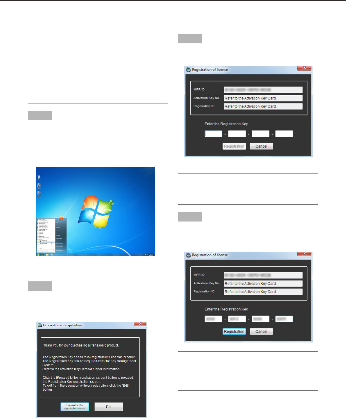
Step 1
Select "Operation Software" from "start" menu
("Start" - "All Programs" - "Panasonic" -
"WV-ASM200 Series" - "Operation Software") or dou-
ble-click the "Operation Software" icon on the desk-
top to launch the operation software.
The explanation window for registration will be
displayed.
Step 2
After reading the message on the explanation win-
dow, click the [Proceed to the registration screen.]
button.
Step 3
Enter the "Registration Key" obtained from the Key
Management System.
Important:
The "Registration Key" can be used only on a PC •
that displays "MPR ID" (used to obtain the key) on
its screen. It cannot be used on other PCs.
Step 4
Click the [Registration] button.
The confirmation window for registration will be
displayed.
Important:
It is impossible to register the "Registration Key" •
of the extension software (option).
Be sure to perform the registration procedure on •
the PC in use.
16
17
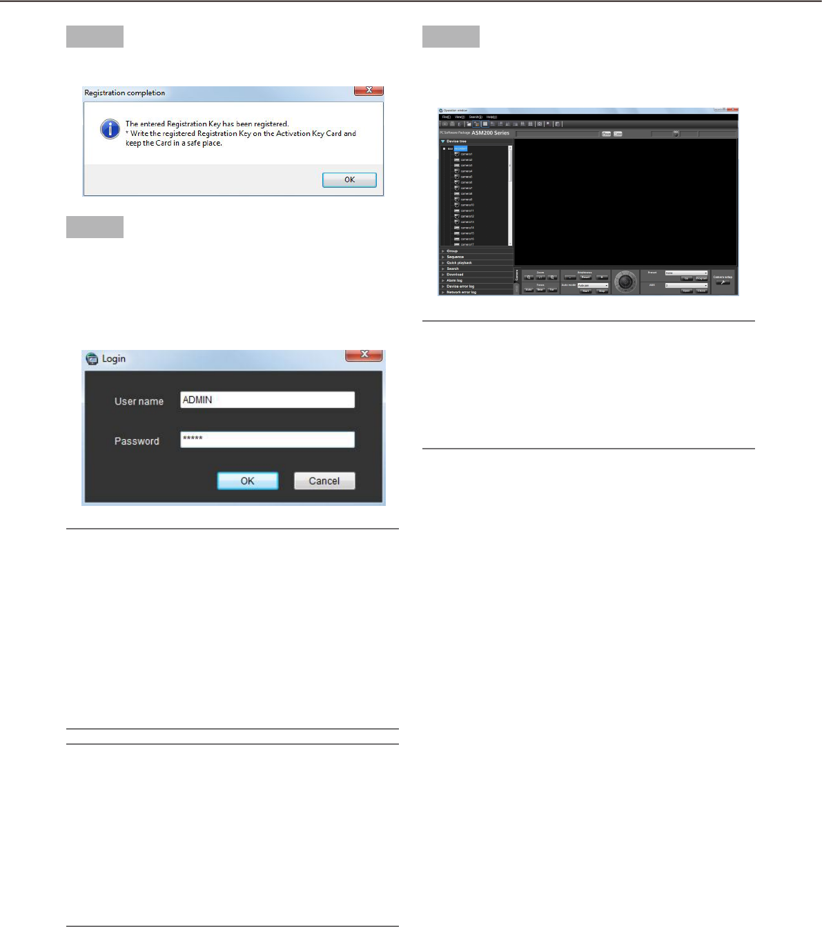
Step 5
Click the [OK] button.
Step 6
Enter the registered user name and password.
Only an administrator is registered when operating
the software just after the installation.
Enter "ADMIN" for "User name" and "12345" for
"Password" respectively.
Important:
It is necessary to close the setup software to start •
the operation software.
The operation software will not start unless the
setup software is closed.
To enhance the security, change the password for •
an administrator before running the software.
It is recommended to change the password for •
the administrator periodically. Refer to the de-
scriptions for how to change the password
(+ page 19).
Note:
It is possible to register a user as the auto login •
user when the same user name is used each time
to log in to the software. The default setting of
"User authentication" for each registered user is
"ON" (required the user name and password en-
tries). Only an administrator can configure the set-
ting of "User authentication" on the setup soft-
ware. Refer to the WV-ASM200 Setup Instructions
(PDF) for further information.
Step 7
Click the [OK] button.
The operation window will be displayed.
Note:
Unless otherwise mentioned, the screenshots of •
the operation window is in the status before the li-
cense for the Extension Software WV-ASE202 is
added. After the license is added, the icon display
on the tool bar will be changed as shown in
page 22.
16
17
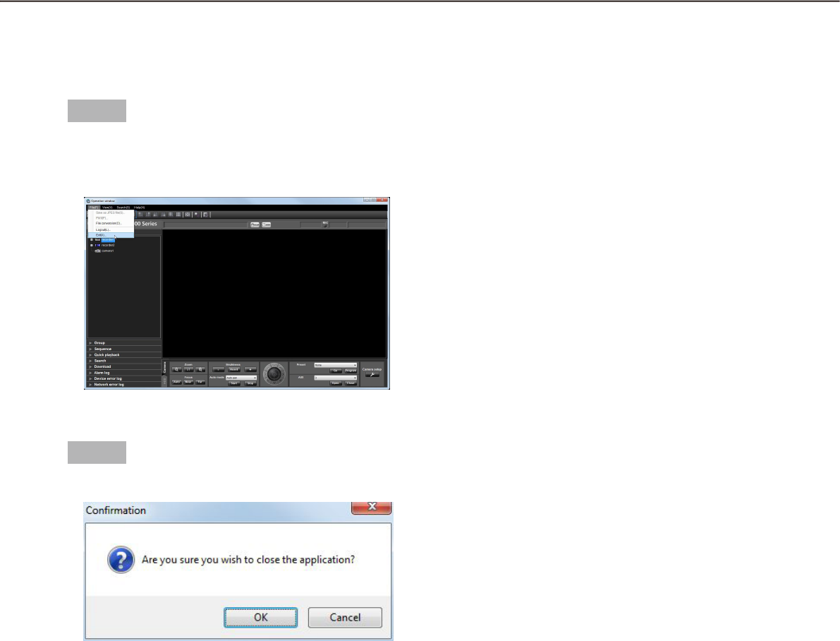
Exit the operation software
Step 1
Select "Exit(X)..." from "File(F)" on the menu bar or
click the [×] button at the top right of the operation
window.
The confirmation window will be displayed.
Step 2
Click the [OK] button.
The operation software will be closed.

18
19
User management
Two types of users, the administrator and the registered users, can be managed with this software.
Only an administrator can configure the settings of this software. When a registered user logged in to the soft-
ware, only the available menus will be displayed according to the user level setting of this registered user. Only
an administrator can configure the user level setting of the registered users. Refer to the WV-ASM200 Setup
Instructions (PDF) for how to configure the user level setting.
Important:
When using this software, apply the user authentication function of this software to manage users even •
though the recorders also have the function.
About the user level setting
It is possible to assign the user level to each user to restrict their operable functions. This software can assign
one of five user levels (LV1 – LV5) to every user. When "LV1" is assigned to a user, this user can operate all
functions of the software except configurations. An administrator can determine the operable functions for each
user by assigning the user level "LV2" – "LV5".
The following functions can be restricted according to the user levels.
Default:
Function LV1 LV2 LV3 LV4 LV5
Display the current settings b
Alarm reset/error reset b
Print/Save as JPEG file b b
File conversion b b
Download b b
Manual recording b
Recorder control b b b
Preset position registration b b b b
Operation of SD memory card b b
Camera control b b b b
Audio (Transmission) b b b b
Display the alarm log b b b b
Display the device error log b b b b
Display the network error log b b b b
Face registration b
Display alarm/Display face search result b b b
18
19
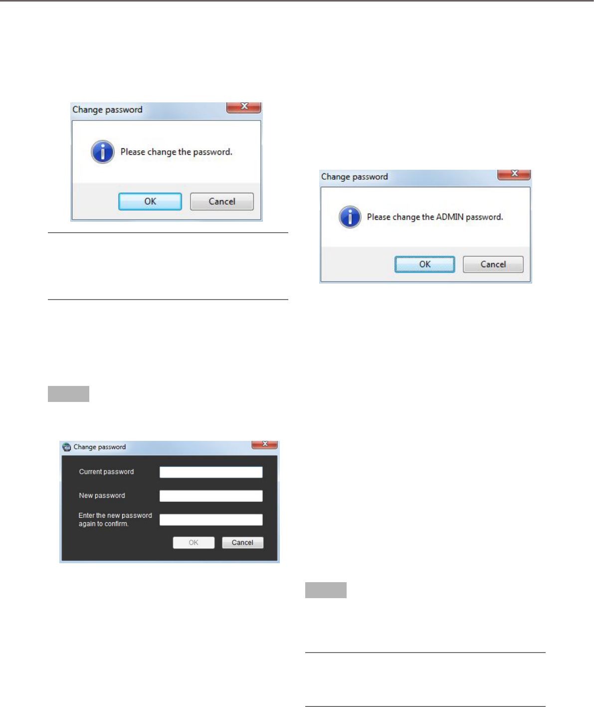
Password’s validation period
The password’s validation period can be determined (31 days/92 days/184 days) by an administrator.
When trying to log in after the set period passed, the message window saying "Please change the password."
will be displayed.
Note:
Even when the validation period has passed, the •
password will be authorized. However, this mes-
sage window will be displayed each time the user
tries to log in.
Change the password
To enhance the security, change the password when this message window is displayed.
Step 1
Click the [OK] button on the message window.
The "Change password" window will be displayed.
n Current password
Enter the current password.
The entered password will be displayed as "*".
n New password
Enter the new password. The entered password will
be displayed as "*".
Enter up to 4 - 8 alphanumeric characters.
When this software is being operated without chang-
ing the password, the following message window say-
ing "Please change the ADMIN password." will be dis-
played.
n Enter the new password again to confirm.
Enter the new password again. Enter the same pass-
word.
The entered password will be displayed as "*".
n [OK] button
Click this button to apply and save the new pass-
word. (The window will close.) The [OK] button cannot
be clicked unless all entries are completed.
n [Cancel] button
Click this button to cancel the entries. (The window
will close.)
Step 2
Complete all of the entry fields on the "Change pass-
word" window, and then click the [OK] button.
The new password will be applied and saved.
Important:
Refer to the WV-ASM200 Setup Instructions (PDF) •
for how to change the password of the adminis-
trator.
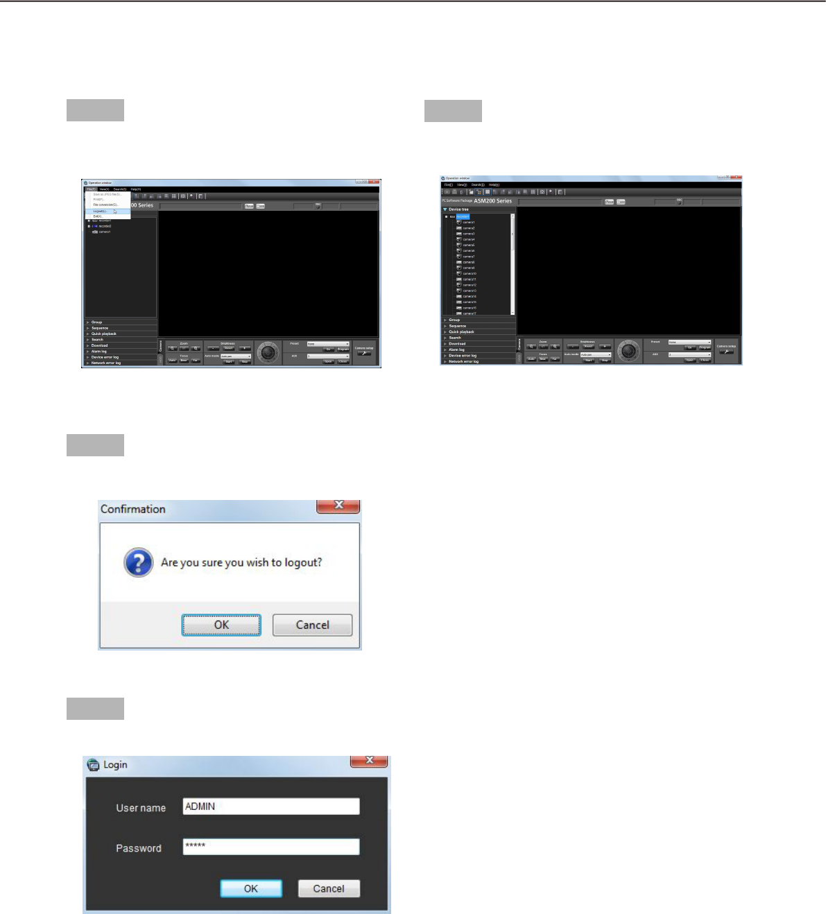
20
21
Step 1
Select "Logout(L)..." under "File(F)" on the menu bar
or double-click the [Logout] icon on the tool bar.
The confirmation window will be displayed.
Step 2
Click the [OK] button.
The "Login" window will be displayed.
Step 3
Enter the registered user name and password.
User switch
It is possible to switch users.
Step 4
Click the [OK] button.
The operation window will be displayed.
20
21
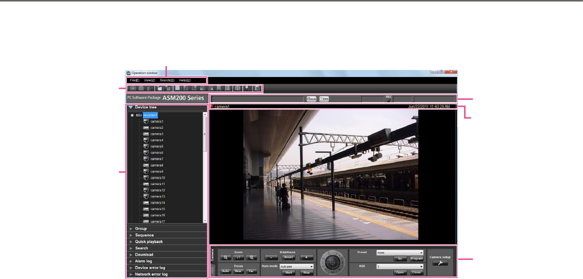
Operation window
The operation window will be displayed when logged in to the operation software. The following are descrip-
tions about each item displayed on the operation window.
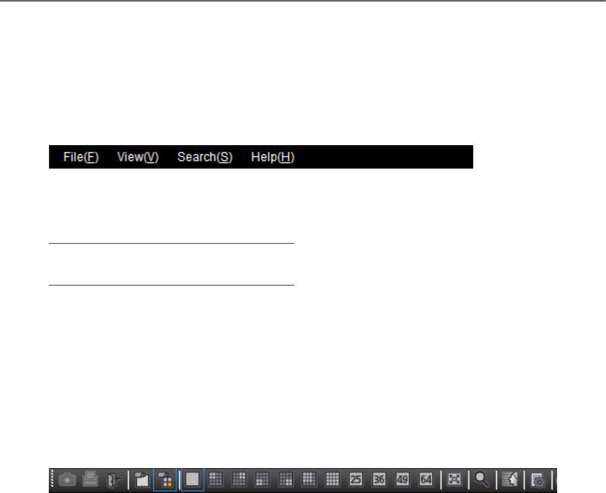
n Menu bar
The menu items are located on the menu bar. Refer
to the descriptions about the "Menu bar" (+ page 22)
for further information.
n Tool bar
The shortcut icons of the menu items are located on
the tool bar. Refer to the descriptions about the "Tool
bar" (+ page 22) for further information.
n Status bar
The following statuses will be displayed on the status
bar.
Display status (live/playback/SD memory data) of •
the images currently being displayed
Playback speed of the images currently being •
played
Recorder (encoder) title/camera title•
Recorder status (recording/copying/deleting of •
data)
Alarm occurrence/error occurrence•
Presence or absence of SD memory data in the •
SD memory card of the camera
Time & date•
Refer to the descriptions about the "Status bar" (+
page 23) for further information.
n Function panel
The function panel is provided on the left of the oper-
ation window. When the desired function bar on the
function panel is clicked, the respective function
panel will be displayed. Refer to the "Function panel"
section (+ page 26) for further information.
n Image display area
Images will be displayed on the selected screen type
(1/4/9/16-screen). The screen type can be changed
simply by clicking the shortcut icons on the tool bar.
When right-clicking on this area, the pop-up menu
will be displayed. (Selection from the displayed pop-
up menu is available only when right-clicking on a
1-screen.) Refer to the descriptions about the pop-up
menu (+ page 28) for further information.
The descriptions of the alarm/error will be displayed
in a pop-up window (notification window) on the
operation window upon an alarm/error occurrence.
Refer to the descriptions about the alarm/event notifi-
cation window (+ page 113) for further information.
n Information display area
Information of the images currently displayed, such
as time & date, camera title and the recording status,
will be displayed in this area.
Refer to the "Information display area" section (+
page 29) for further information.
Menu bar
Tool bar
Function panel
Information dis-
play area
Status bar
Operation panel
22
23
n Operation panel
The cameras and recorders are operable with this
panel. Refer to the description about the "Camera
operation panel" (+ page 29) and about the
"Playback operation panel" (+ page 32) for further
information.
Menu bar
n File(F)
Contains the following menus; "Save as JPEG file",
"Print", "File conversion", "Logout" and "Exit".
Note:
"Save as JPEG file" and "Print" are also available •
from the pop-up menu displayed by right-clicking.
n View(V)
Contains the following menus; "Function panel",
"Operation panel", "Camera/time & date", "Camera
selection", "Number of area", "Full screen", "Live win-
dow", "Map window" and "Decoder control" (after the
license for the WV-ASE204 is added).
n Search(S)
Contains the shortcut menu to open the "Search"
window.
n Help(H)
It is possible to indicate the version information and
license registration information.
n [Save as JPEG file] icon
Click this icon to save the image currently being dis-
played as a JPEG file.
n [Print] icon
Click this icon to print the image currently being dis-
played.
n [Logout] icon
Click this icon to log out of the software. The login
window will be displayed when this icon is clicked.
n [Display images on 1-screen] icon
When the device tree or the camera icon on the map
is clicked, a live image on a 1-screen will be dis-
played.
Tool bar
The following are the descriptions of icons located from the left to the right.
n [Display images on the selected area] icon
When the device tree or the camera icon on the map
is clicked, live images will be displayed in the
selected frame.
n [1] icon
Click this icon to display images on a 1-screen.
n [4A] icon
Click this icon to display images using 4 areas at the
upper left of a 16-screen.
n [4B] icon
Click this icon to display images using 4 areas at the
upper right of a 16-screen.

22
23
n [4C] icon
Click this icon to display images using 4 areas at the
lower left of a 16-screen.
n [4D] icon
Click this icon to display images using 4 areas at the
lower right of a 16-screen.
n [9] icon
Click this icon to display images using 9 areas at the
upper left of a 16-screen.
n [16] icon
Click this icon to make the image display area into a
16-screen.
n [25] icon (Available after the license for the
WV-ASE202 is added)
Click this icon to make the image display area into a
25-screen.
n [36] icon (Available after the license for the
WV-ASE202 is added)
Click this icon to make the image display area into a
36-screen.
n [49] icon (Available after the license for the
WV-ASE202 is added)
Click this icon to make the image display area into a
49-screen.
n [64] icon (Available after the license for the
WV-ASE202 is added)
Click this icon to make the image display area into a
64-screen.
n [Full screen] icon
Click this icon to display the image currently being
displayed on a full screen.
n [Search] icon
Click this icon to display the "Search" window.
Refer to the descriptions about the "Search window"
(+ page 35) for further information.
n [Face search] icon (Available after the
license for the WV-ASE231 is added)
Click this icon to launch the face search monitor.
n [File conversion] icon
Click this icon to display the window to convert an
n3r file into an mp4 file. Refer to the "Convert a file to
the standard format" section (+ page 102) for further
information.
n [Decoder control] icon
Click this icon to display the "Decoder control" win-
dow. Refer to the descriptions about the "Control a
decoder" (+ page 104) for further information.
Status bar
Important:
Check if the model in use is compatible with each function. •
n Recorder title/camera title
Source (recorder (encoder) title and the camera title)
of the image currently being displayed will be dis-
played in this area.
n [ALM] button
The button will be used when the emergency record-
ing is being performed or when an event occurred.
When the button is clicked, the alarm action will be
canceled.
Note:
When the recorder in use is the ND300 (Version •
4.69 or earlier) or the HD300, the error action also
will be canceled.
When the recorder in use is the ND300 or the •
HD300, the button will not be used even when the
emergency recording is being performed.
This button will not be displayed when using •
ASR500.

24
25
n [ERR] button
The button will be used when an error occurred.
When the button is clicked, the error action will be
canceled.
Note:
When the recorder in use is the ND300 (Version •
4.69 or earlier) or the HD300, the alarm action also
will be canceled.
When the recorder in use is the WJ-HD300, the •
error action will not be canceled even when the
button is clicked.
In this case, refer to the operating instructions of
the recorder in use for how to cancel an error ac-
tion.
This button will not be displayed when using •
ASR500.
n [SD] button (Button to obtain the SD
memory data)
When the SD memory card in the camera connected
to the recorder contains recorded images, the letters
"SD" on the [SD] button will be displayed in red.
When the button is clicked, the recorded images on
the SD memory card will be transferred to the
recorder.
Important:
When the recording rate for the SD memory re-•
cording is not set, the SD memory data obtain
button will not be displayed. Refer to the operat-
ing instructions of the recorder in use for how to
set the recording rate for the SD memory record-
ing.
The SD memory data cannot be obtained during •
the emergency recording. Refer to the operating
instructions of the recorder in use for further infor-
mation about the emergency recording.
Depending on the recorder in use, all login users •
will be forcibly logged out and recording of im-
ages from all cameras currently being performed
will stop when obtainment of the SD memory data
starts.
Note:
The letters "SD" on the [SD] button will be dis-•
played in blue when there is no recorded image in
the SD memory card.
When the [SD] button is clicked while the letters •
"SD" are displayed in blue, this software will
check the presence of recorded image on the SD
memory card. Images saved on the SD memory
card will be transmitted to the recorder depending
on the model of the recorder in use.
When the [SD] button is clicked while the letters •
"SD" are displayed in red, recorded images on the
SD memory card will be transferred to the re-
corder (SD memory data).
n [Mic input] button
Click this button to turn on/off the audio reception
(from camera to PC). When is displayed, audio
will not be heard.
Note:
When right-clicking on this button, the pop-up •
menu will be displayed. It is possible to change
the volume level of audio reception by selecting
"High", "Middle" or "Low" from the displayed
pop-up menu.
When displaying images on a multi-screen, audio •
will be transmitted to the camera which is the
source of images displayed in the upper-left area
of the multi-screen. When another area is se-
lected, audio associated with images displayed in
the upper-left area of the multi-screen will still be
heard, though this button will disappear.
When audio is being transmitted to the same •
camera by another user, this button will turn to .
In addition, audio from the camera will not be
heard. (Audio will be heard even when audio is
being transmitted depending on the model in use.)
This button will not be displayed when using •
ASR500.
n [Audio output] button
Click this button to turn on/off the audio transmission
(from PC to camera). When is displayed, audio will
not be heard.
Note:
Volume level of audio transmission cannot be •
changed. (Depending on the camera in use, vol-
ume level of audio transmission can be adjusted
by configuring the settings of the camera.)
When displaying images on a multi-screen, audio •
will be transmitted to the camera which is the
source of images displayed in the upper-left area
of the multi-screen. When another area is se-
lected, audio will still be transmitted to the camera
which is the source of images displayed in the up-
per-left area, though this button will disappear.
When audio is being transmitted to the same •
camera by another user, this button will turn to .
In addition, audio from the camera will not be
heard.

24
25
It is possible to transmit audio up to 5 minutes per •
transmission. When 5 minutes elapsed, the audio
reception will be turned on automatically.
To transmit audio again, click the [Audio transmis-
sion] button.
This button will not be displayed when using •
ASR500.
n [LIVE]/[PLAY]/[SD PLAY]
Indicates the type (live/playback/SD memory data
playback) of the images currently being displayed.
n [Step 1] - [Step 7]
Indicates the playback speed. ( ): Smooth & fast play-
back mode
[Step 1]: Normal playback speed
[Step 2]: Approx.4x playback speed (Approx.2x
playback speed)
[Step 3]: Approx.8x playback speed (Approx.4x
playback speed)
[Step 4]: Approx.16x playback speed (Approx.8x
playback speed)
[Step 5]: Approx.32x playback speed (Approx.16x
playback speed)
[Step 6]: Approx.48x playback speed (Approx.32x
playback speed)
[Step 7]: Approx.96x playback speed (Approx.64x
playback speed)
Note:
ASR500 plays recorded images in the high-speed •
playback smooth mode. The maximum playback
speed using ASR500 is [Step 5].
n REC indicator
This indicator will light red when the recording of the
images currently selected is being performed.
Note:
This indicator will not be displayed when using •
ASR500.
n [COPY]/[DELETE]
[COPY]: Indicates that copying of image data is being
performed.
[DELETE]: Indicates that deletion of image data is
being performed.
n Time & date
When displaying live images, the time & date of the
selected device will be displayed. Time & date will not
be displayed except for some devices when images
directly from the camera are being displayed or when
images from a camera that is not registered in the
recorder are being displayed.
When displaying recorded images, the recording time
& date will be displayed.
When "24h" is selected for "Time format" (+ Setup
Instructions (PDF)), the indications will not be dis-
played.
The time & date will be followed by an asterisk "*"
when the daylight saving time is applied.
n Buffering
Indicates that the images are being buffered during
playback. When images are being buffered, playback
will be paused. The playback will start when the buff-
ering of images are completed.
Note:
This indicator will work only when the recorder in •
use is ASR500.
26
27
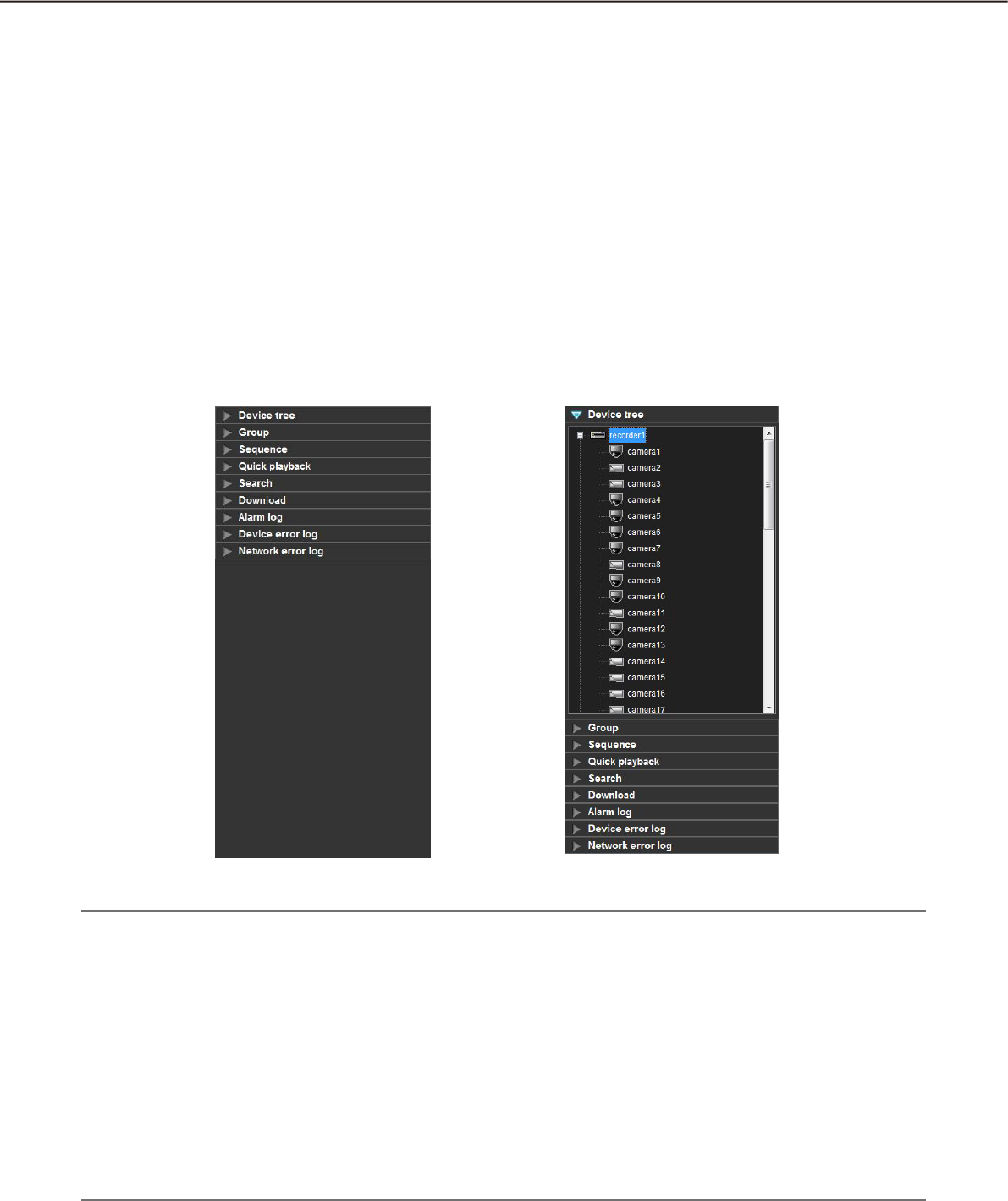
Function panel
The following are available using the function panel located at the left side of the operation window.
Display the device tree (the icons of the connected devices in the tree view), and display images by clicking •
the desired camera icon
Group display•
Sequence display•
Quick playback•
Search•
Download•
Display the alarm log•
Display the device error log•
Display the network error log•
When one of the function bars is clicked, the respective function panel will open. (It is impossible to open two
or more panels at the same time.)
Note:
Refer to the following about the descriptions of how to operate each function panel.•
"Device tree" panel Confirm the registered devices (+ page 45)
"Group" panel Display images from the cameras registered as a group (group display)
(+ page 52)
"Sequence" panel Display images from the cameras registered as a group sequentially
(sequence display) (+ page 53)
"Quick playback" panel Play images using the "Quick playback" panel (+ page 69)
"Search" panel Play recorded images using the "Search" panel (+ page 77)
"Download" panel Download recorded images (+ page 95)
"Alarm log" panel "Alarm log" panel (+ page 120)
"Device error log" panel "Device error log" panel (+ page 121)
"Device error log" panel "Network error log" panel (+ page 122)
B
26
27
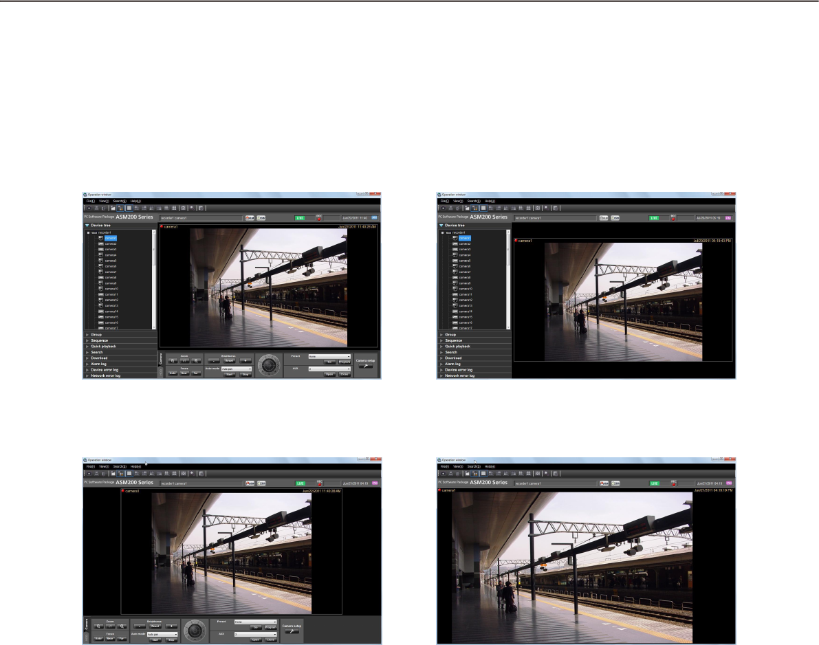
Layout of the operation window
It is possible to hide the operational panel and the function panel of the operation window as follows.
Refer to the "Menu bar" section (+ page 22) for further information.
n With the operation panel and the function
panel
n Without the operation panel
n Without the function panel n Without the operation panel and the
function panel
28
29
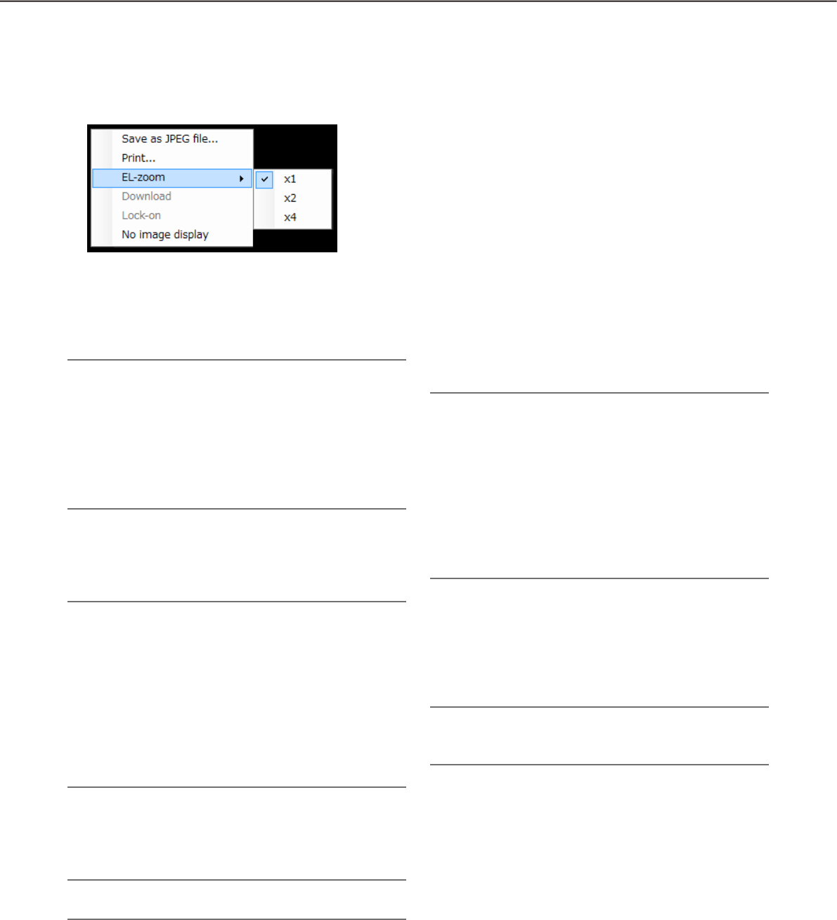
Pop-up menu
When right-clicking on the image display area, the pop-up menu will be displayed. (Selection from the dis-
played pop-up menu is available only when right-clicking on a 1-screen.)
n Save as JPEG file...†
Select this to save the image currently being dis-
played as a JPEG file.
Note:
"Save as JPEG file..." on the pop-up menu will not •
be displayed when the user is restricted by the
user level determined by the administrator to save
an image as a JPEG file.
Refer to the "About the user level setting" section
(+ page 18) for further information about the user
level.
n Print...†
Select this to print the image currently being dis-
played.
Note:
Select this to print the image currently being dis-•
played.
"Print..." on the pop-up menu will not be dis-•
played when the user is restricted by the user
level determined by the administrator to print im-
ages.
Refer to the "About the user level setting" section
(+ page 18) for further information about the user
level.
n EL-zoom†
Select this to enlarge the image currently being dis-
played. "x1", "x2" and "x4" are available.
Note:
This button will not be used when using ASR500.•
n Download...†
Select this to open the "Download" panel. Information
(recorder title/camera title/time & date) of the
recorded image currently being played will be dis-
played in the opened "Download" panel.
Note:
"Download" on the pop-up menu will not be dis-•
played when the user is restricted by the user
level determined by the administrator to download
recorded images.
Refer to the "About the user level setting" section
(+ page 18) for further information about the user
level.
When displaying live images, it is impossible to •
select "Download" on the pop-up menu.
n Lock-on†
Select this to start auto track for the object on the
clicked point. Depending on the target object or sur-
rounding environment, this function may not work
correctly.
Note:
This function is available only when the camera in •
use is WV-SC386 or WV-SW396.
n No image display
Clear the currently displayed image.
28
29
n REC indicator
This indicator will light when the recording of the
images currently selected are being performed.
Note:
This indicator will not be displayed when using •
ASR500.
n Camera name
The camera title as the source of the image currently
being displayed will be displayed.
n Time & date
Time & date will be displayed. Time & date will not be
displayed except for some devices when images
directly from the camera are being displayed or when
images from a camera that is not registered in the
recorder are being displayed. The time & date will be
followed by an asterisk "*" when the daylight saving
time is applied.
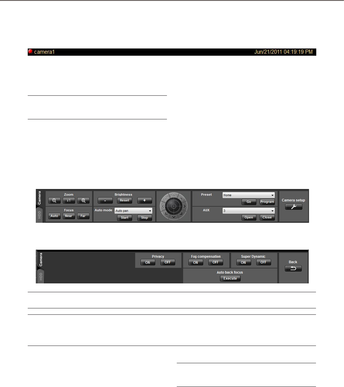
Camera operation panel
Display when the [Camera setup] button is clicked
n Zoom
Zooming can be adjusted by clicking the [-] (wide)
button or the [+] (tele) button.
When clicking the [x1] button, the zoom ratio will be
reset.
Note:
Zooming is available using the wheel on the wheel •
mouse.
Information display area
Information of the images currently displayed, such as time & date, camera title and the recording status, will be
displayed in this area.
Important:
Check if the model in use is compatible with each function. •
Note:
Operation of the camera operation panel works only for the camera respective the selected image.•
The camera operation panel will not be displayed when the user is restricted by the user level determined by •
the administrator to operate the cameras.

30
31
n Focus
The auto focus function can be performed by clicking
the [Auto] button.
Focusing can be manually adjusted by clicking the
[Near] button or the [Far] button.
n Auto mode
Select the auto function from the following.
Auto track: The camera automatically tracks motion
of the subject displayed in the image display area.
Auto pan: The camera automatically moves from the
start point to the end point set in advance.
Preset sequence: The camera automatically moves to
the preset positions in numerical order of the pre-
set position numbers.
Sort: The camera automatically moves to the closest
preset position from the current position.
Patrol1 - Patrol4: The camera automatically traces the
route set in advance.
When the [Start] button is clicked, the selected auto
function will start.
When the [Stop] button is clicked, the selected auto
function will stop.
Note:
The auto functions are available only when the •
camera in use has these functions. Refer to the
operating instructions of the camera in use for fur-
ther information about the auto function of the
camera.
While "Quad PTZ" is selected for the image cap-•
ture mode of Fisheye cameras, the auto functions
will be performed for the image displayed at the
upper left area of the 4-screen.
n Control pad
Clicking the buttons around the control pad can move
(pan/tilt) a camera in the clicked direction. Clicking
inside the control pad also can adjust the vertical/hor-
izontal position (pan/tilt) of the displayed live images.
Panning/tilting speed will be faster if a clicked point
gets farther from the center point of the control pad.
Note:
Panning and tilting are available only when the •
camera in use is a PTZ camera.
Clicking a point on the image display area can •
move (pan/tilt) a camera in the clicked direction.
n Brightness
Brightness can be adjusted by clicking the [–] (darker)
button or the [+] (brighter) button.
It is possible to reset the set brightness by clicking
the [Reset] button.
n Preset
Select a preset number from the following.
Home/1 - 256
Click the [Go] button after selecting a preset number.
The camera will move to the selected preset position.
When the [Program] button is clicked after selecting a
preset number, the current position will be registered
as the preset position of the selected preset position
number.
Note:
Preset position function is available only when the •
camera in use is a PTZ camera.
It is impossible to register a position when •
"Home" is selected for the preset position
number.
It is possible to register the preset position only •
when the user is not restricted by the user level
determined by the administrator to operate the
cameras.
Refer to the "About the user level setting" section
(+ page 18) for further information about the user
level.
Refer to the operating instructions of the recorder •
and the camera in use for further information
about the available preset position numbers.
While "Quad PTZ" is selected for the image cap-•
ture mode of Fisheye cameras, the preset position
currently displayed at the upper left area of the
4-screen will be registered.
n AUX
Select an AUX OUT connector from the following.
1/2/3
When the [Open] button is clicked, the selected AUX
OUT connector will be opened.
When the [Close] button is clicked, the selected AUX
OUT connector will be closed.
n Camera setup
Click this button to move to the panel to configure the
settings for the camera.

30
31
n Super Dynamic
Determine whether to use or not use the Super
Dynamic (SD) function of the camera.
ON: Use the Super Dynamic function.
OFF: Not to use the Super Dynamic function.
Note:
Cameras supporting the Super Dynamic function •
or Wide dynamic range (WDR) function are com-
patible with this setting.
The Super Dynamic function is available only •
while images are being displayed directly from the
camera when a recorder is registered.
n Auto back focus
When the [Execute] button is clicked, the auto back
focus function will be activated to adjust the back
focus automatically according to the photographic
subject at the center of the screen.
Note:
Cameras supporting the auto back focus function •
are compatible with this setting.
The auto back focus function is available only •
while images are being displayed directly from the
camera when a recorder is registered.
n Fog compensation
Determine whether to use or not use the fog compen-
sation function of the camera.
ON: Use the fog compensation function.
OFF: Not to use the fog compensation function.
Note:
Cameras supporting the fog compensation func-•
tion are compatible with this setting.
The fog compensation function is available only •
while images are being displayed directly from the
camera when a recorder is registered.
n Privacy
Privacy mode allows you to protect your privacy by
hiding the lens inside the camera, preventing camera
images from being seen.
ON: Use the privacy mode
OFF: Not use the privacy mode
Note:
The privacy mode is available only when using •
WV-SF448.
The privacy mode is supported only when the •
camera direct reception is selected for the re-
corder registration.
Back
Click this button to return to the camera operation
panel.

32
33
n [PREV RECORD] button
Playback will start after skipping to the previous
recorded image.
n [REW] button
Fast reverse playback will be performed.
Playback speed for fast reverse playback will be
changed in the following order each time this button
is clicked: Step2 (Approx.4x) Step3 (Approx.8x)
Step4 (Approx.16x) Step5 (Approx.32x) Step6
(Approx.48x) Step7 (Approx.96x)
Note:
When fast reverse playback is performed while •
playing images on the HD600, playback speed will
be changed in the following order: Step 1
Step 2 Step 3...
When using ASR500, the maximum playback •
speed is [Step 5].
n [REV PLAY] button
Reverse playback of a recorded image will be per-
formed.
When this button is clicked during fast playback or
fast reverse playback, reverse playback at normal
speed will start.
Note:
When playing MPEG-4 or H.264 images, some •
frames of recorded images may not be displayed.
Reverse playback will be performed with the set
refresh interval of the camera.
n [PLAY] button
Playback of a recorded image will be performed.
When this button is clicked during fast playback or
fast reverse playback, playback at normal speed will
start.
n [FF] button
Fast playback will be performed.
Playback speed for fast playback will be changed in
the following order each time this button is clicked:
Step2 (Approx.4x) Step3 (Approx.8x)
Step4 (Approx.16x) Step5 (Approx.32x)
Step6 (Approx.48x) Step7 (Approx.96x)
Note:
In the smooth & fast playback mode, playback •
speed will be changed in the following order:
Step2 (Approx.2x) Step3 (Approx.4x) Step4
(Approx.8x) Step5 (Approx.16x) Step6
(Approx.32x) Step7 (Approx.64x)
The smooth & fast playback mode is available •
only when the firmware of the ND400 is Version
2.5 or later. When the firmware of the ND400 is
earlier or another recorder is used, frames will be
skipped even in the smooth & fast playback
mode.
When using ASR500, the maximum playback •
speed is [Step 5].
Playback operation panel
Important:
Check if the model in use is compatible with each function. •
Note:
The playback operation panel will not be displayed when the user is restricted by the user level determined •
by the administrator to play recorded images.
Refer to the "About the user level setting" section (+ page 18) for further information about the user level.
The playback operation panel will not be displayed when displaying images from a camera that is not regis-•
tered in the recorder.
When displaying images on a multi-screen, images displayed in all areas of a multi-screen will be controlled •
simultaneously using the playback operation panel.

32
33
n [NEXT RECORD] button
Playback will start after skipping to the next recorded
image.
When this button is clicked while playing the latest
recorded image, the current playback will continue.
n [REV SKIP] button
Playback will start after skipping to the point of the
set amount of time backward.
Note:
This button will not work when the playback point •
is at the start point or the end point of the re-
corded images.
This button may sometimes not work when the •
time & date of the recorded images is around the
time when shifting to daylight saving time.
When clicking this button while playing MPEG-4 •
or H. 264 images, a skipped point may be a few
seconds later from a point to be skipped with the
selected amount of time.
n [PREV IMAGE] button
The previous frame will be displayed when this button
is clicked during pausing.
Note:
When playing MPEG-4 or H.264 images, some •
frames of recorded images may not be displayed.
Reverse frame by frame playback will be per-
formed with the set refresh interval of the camera.
n [PAUSE] button
Playback will stop when this button is clicked during
playback. Playback will resume when this button is
clicked during pausing.
n [STOP] button
Playback will stop and live images will be displayed.
n [NEXT IMAGE] button
The next frame will be displayed when this button is
clicked during pausing.
n [SKIP] button
Playback will start after skipping to the point of the
set amount of time forward.
Note:
This button will not work when the playback point •
is at the start point or the end point of the re-
corded images.
This button may sometimes not work when the •
time & date of the recorded images is around the
time when shifting to daylight saving time.
When clicking this button while playing MPEG-4 •
or H. 264 images, a skipped point may be a few
seconds later from a point to be skipped with the
selected amount of time.
n SKIP TIME
Select an amount of time to skip from the following.
30s/1min/5min/10min/30min/60min
n Speed
Click the [–] button or the [+] button while displaying
playback recorded images on the WJ-HD300 on a
1-screen to adjust the image refresh intervals of play-
back images.
When the [–] button is clicked, the image refresh
intervals will become longer. When the [+] button is
clicked, the image refresh intervals will become
shorter.
n [Text] button
When playing recorded images on a 1-screen, text
information can be added. The "Edit text" window will
be displayed when this button is clicked during paus-
ing playback. Refer to page 101 for further informa-
tion about the "Edit text" window.
Note:
This function is available only when the recorder in •
use is the WJ-ND300 or the WJ-HD300.
n [REC START]/[REC STOP] button
Manual recording will start or stop.
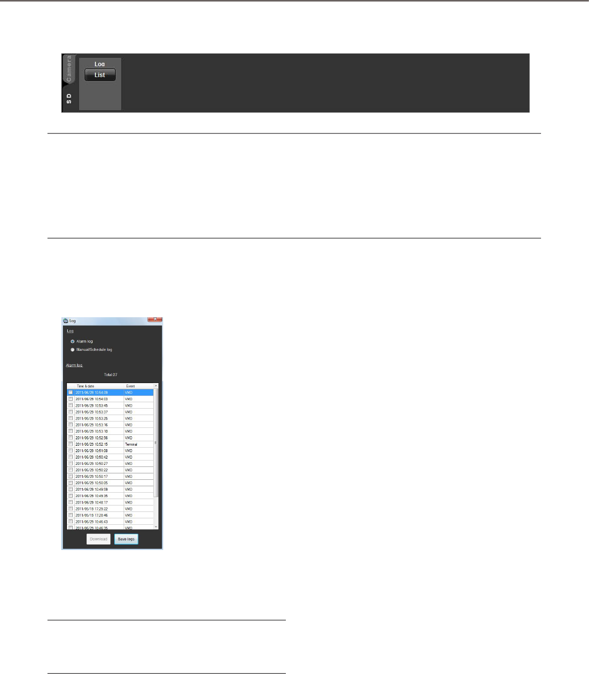
34
35
SD operation panel
Note:
The SD operation panel will not be displayed when the user is restricted by the user level determined by the •
administrator to operate the SD memory card.
The SD operation panel will not be displayed when displaying images from a camera that is registered in the •
recorder.
The SD operation panel will not be displayed when displaying images from WV-NP244,WV-NP1000/•
NP1004, WV-NS202, WV-NS202A, WV-NF284, WV-NW484, WV-NS950/NS954, WV-NW960/NW964,
WV-NP304, WV-NF302.
n [List] button:
When this button is clicked, the log list window will be
displayed in a newly opened window.
Click to select the log list to be displayed from "Log".
Images from the selected log list will be dis-
played.
Note:
The fist-time display is the alarm log list. From the •
next time, the log list most recently selected will
be displayed.
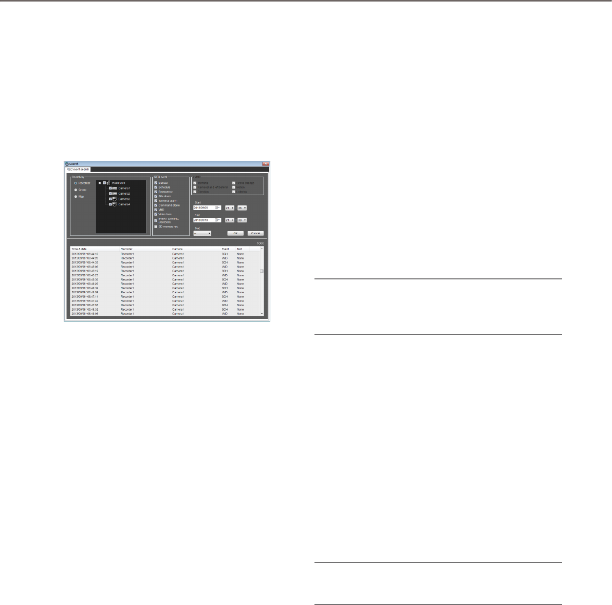
34
35
Search window
When "Search(S)..." under "Search(S)" on the menu bar is selected or the [Search] icon on the tool bar is
clicked, another window will open and the "Search" window will be displayed. The search function consists of
"REC event search" and "VMD search".
REC event search tab
This tab searches images from the recorded images of the recorder by specifying search criteria such as a REC
event.
n Search by
Select the search target from the following.
Recorder: Select recorders to be searched. When
"Recorder" is selected, the recorders will be dis-
played in the tree view. Select the recorders and
the cameras to be searched by checking the
checkbox.
Group: Select the groups to be searched. When
"Group" is selected, the group list will be dis-
played. Select the groups to be searched by
checking the checkbox.
Map: Select the maps to be searched. When "Map" is
selected, the map list will be displayed. Select the
maps to be searched by checking the checkbox.
n REC event
Select the recording event type to be searched.
Manual: Select to search for images recorded by
manual recording.
Schedule: Select to search for images recorded by
the schedule recording.
Emergency: Select to search for images recorded by
the emergency recording.
Site alarm: Select to search for images recorded
upon the site alarm occurrence.
Terminal alarm: Select to search for images recorded
upon the terminal alarm occurrence.
Command alarm: Select to search for images
recorded upon the command alarm occurrence.
VMD: Select to search for images recorded upon the
video motion detection.
Video loss: Select to search for images recorded
upon the video signal loss.
SD memory rec.: Select to search for SD memory
data.
EVENT LINKING (ASR500): Search images recorded
by the event linking.
Note:
"SD memory rec." is unavailable to select together •
with other recording event types. To search for
the SD memory data, select "SD memory" alone.
n i-VMD
Select the i-VMD type to be searched.
Terminal alarm: Select to search for images recorded
upon the terminal alarm occurrence.
Removal and left behind: Select to search for images
recorded upon the detection relating to removal and
left behind.
Direction: Select to search for images recorded upon
the detection relating to direction.
Scene change: Select to search for images recorded
upon the detection relating to scene change.
Motion: Select to search for images recorded upon
the detection relating to motion.
Loitering: Select to search for images recorded upon
the detection relating to loitering.
Note:
i-VMD search is available only when HD600 is se-•
lected for the search target.
n Text
It is possible to search for recorded images only with
or without text information.
Select "Added" or "None".
When"--" is selected, images will be searched
regardless of with or without text information.
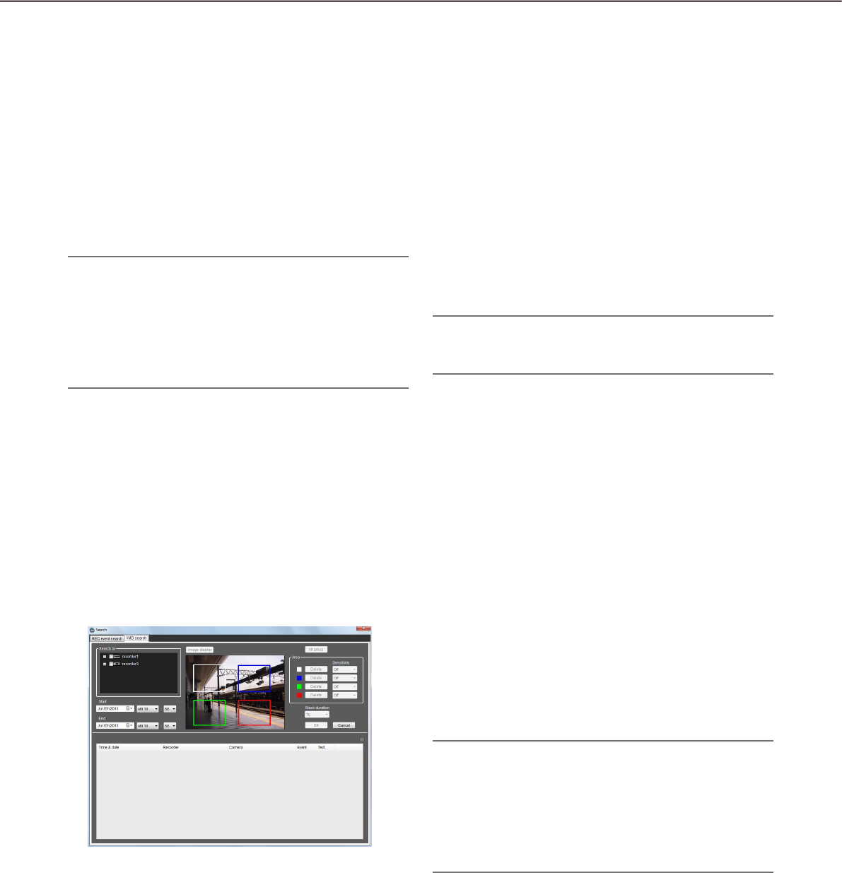
36
37
n Start
Select the start time between "Jan/01/2008" and
"Dec/31/2034". Select a number for hour from
"AM12" - "PM11". Select a number for minute from
"00" - "59".
n End
Select the end time between "Jan/01/2008" and
"Dec/31/2034". Select a number for hour from
"AM12" - "PM11". Select a number for minute from
"00" - "59".
Note:
When the software in use is European specifica-•
tion, select the start time and the end time from
the following.
Date: Between "01/01/2008" and "31/12/2034"
Hour: Between "0" and "23"
Minute: Between "00" and "59" (1 minute step)
n [OK] button
Click this button to start searching.
n [Cancel] button
Click this button to cancel the edited search condi-
tions and close the "Search" window.
n Search result number
Search result number will be displayed.
n Search result list
Search result will be displayed in list form. When a
result is clicked, the "Search" window will close and
the selected image will be displayed on a 1-screen.
When playback of the selected result starts, the
descriptions of the selected result will be displayed in
the search panel of the operation window.
Note:
No image will be displayed when search result •
number is "0".
[VMD search] tab
This tab searches for times and dates of the images containing a motion from the recorded images of the
recorder.
This function is available only with ND400, HD600 or NV200.
If ND400, HD600 or NV200 is registered, the VMD search tab will be displayed.
n Search by
Select a recorder and a camera to be searched.
n Start
Select the start time between "Jan/01/2008" and
"Dec/31/2034". Select a number for hour from
"AM12" - "PM11". Select a number for minute from
"00" - "59".
n End
Select the end time between "Jan/01/2008" and
"Dec/31/2034". Select a number for hour from
"AM12" - "PM11". Select a number for minute from
"00" - "59".
Note:
When the software in use is European specifica-•
tion, select the start time and the end time from
the following.
Date: Between "01/01/2008" and "31/12/2034"
Hour: Between "0" and "23"
Minute: Between "00" and "59" (1 minute step)
n [Image display] button
Import the image of the start time & date from the
recorder.
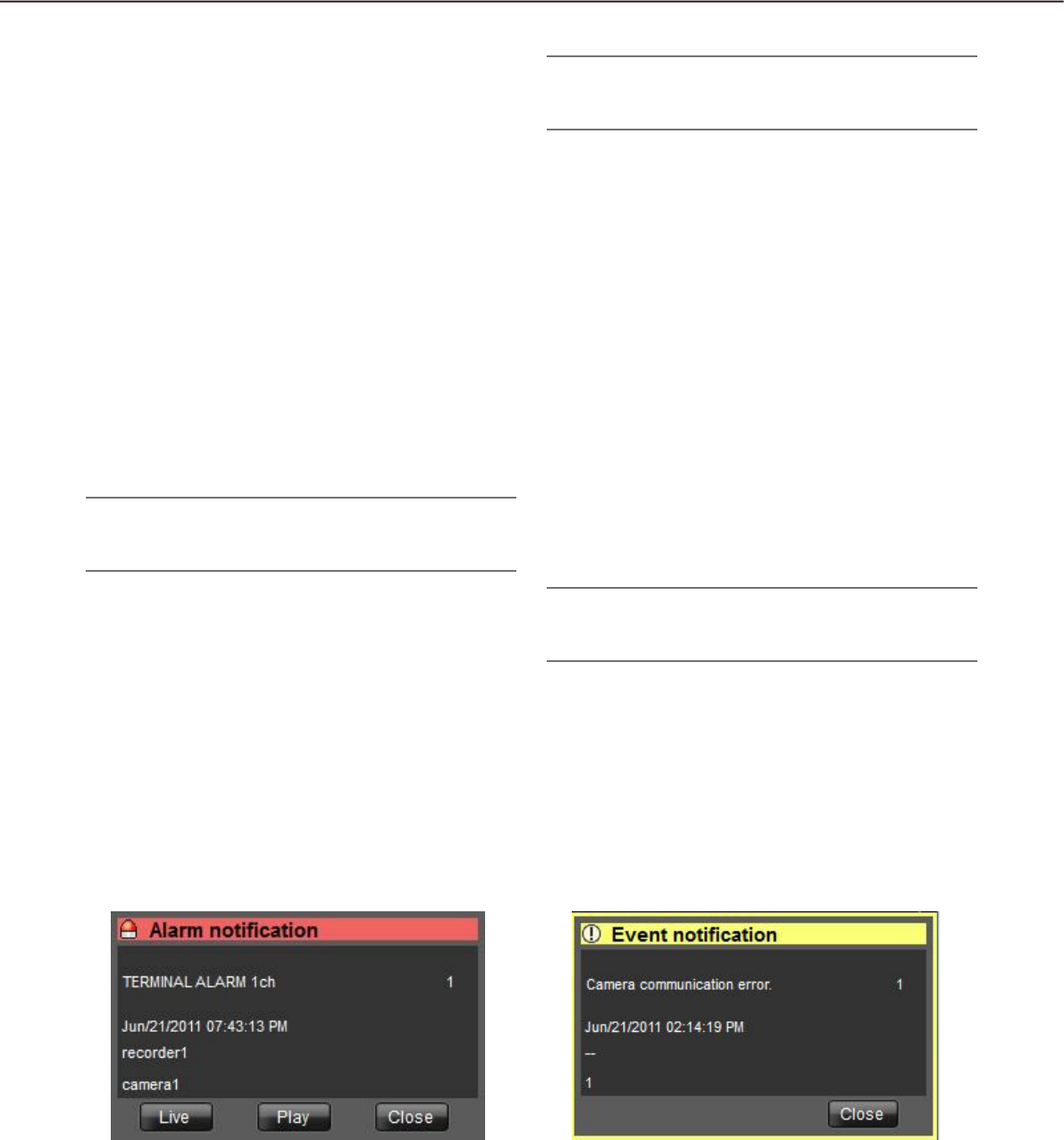
36
37
n Image area
Display the images obtained from the recorder.
The areas to be searched for are specified by drag-
ging in the image area. Up to 4 areas can be speci-
fied.
n [All areas] button
Select all the areas to be searched for.
n [Delete]
Delete the same colored areas.
n Sensitivity
Select the sensitivity for each area from the following.
Off: Does not detect the motion in this area.
Low: Low sensitivity
Mid: Standard sensitivity
High: High sensitivity
Note:
Selection of sensitivity is available only when •
HD600 is selected for the search target.
n Mask duration
Select the duration to mask detection in the same
area from the following.
When the recorder in use is the HD600:•
1s/1min/60min/24h
When the recorder in use is the NV200:•
1s/5s/10s/30s/1min/5min/10min
Note:
Selection of mask duration is available only when •
HD600 or NV200 is selected for the search target.
n [OK] button
Click this button to start searching.
n [Cancel] button
Click this button to cancel the edited search condi-
tions and close the "Search" window.
n Search result number
Search result number will be displayed.
n Search result list
Search result will be displayed in list form. When a
result is clicked, the "Search" window will close and
the selected image will be displayed on a 1-screen.
When playback of the selected result starts, the
descriptions of the selected result will be displayed in
the search panel of the operation window.
Note:
No image will be displayed when search result •
number is "0".
Alarm/event notification message
A pop-up window (notification window) will be displayed when an alarm or an error occurred.
n Alarm notification
Notifies of an alarm occurrence.
n Event notification
Notifies of a device error occurrence or a network
error occurrence.

38
39
License registration message
n License registration message
Notifies that the license for this software has not been
registered.
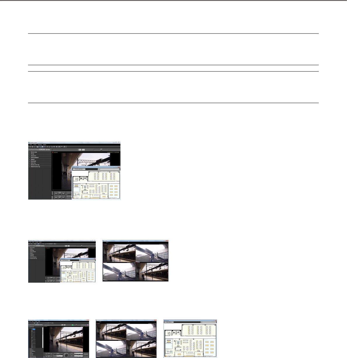
38
39
Outline of the multi-monitor function
The multi-monitor function using up to four PC monitors is available, and it makes possible to display the oper-
ation window, the live window and map window simultaneously.
Important:
To use the multi-monitor function, it is necessary to purchase the Extension Software WV-ASE201 and add •
the license.
To user the multi-monitor function, it is necessary to install an additional video card on the PC in use.•
Note:
Availability of the live window can be determined on the setup software. Refer to the WV-ASM200 Setup •
Instructions (PDF) for further information.
After the license for the WV-ASE202 is added, it will become possible to use up to 4 live windows.•
The following are the examples when using the multi-monitor function.
n 1 PC monitor (Not use the live window)
When using a single PC monitor, the operation with
the operation window and the map window without
using the live window is suitable.
n 2 PC monitors (Use the live window)
<When using two PC monitors>
Operation while displaying the operation window and
the map window on one of the two PC monitors and
the live window on the other PC monitor is suitable.
n 3 PC monitors (Use the live window)
<When using three PC monitors>
Operation while displaying the operation window, the
live window and the map window on each of three PC
monitors is suitable.
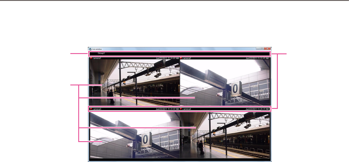
40
41
Live window
The following are descriptions about each item displayed on the live window.
n Group information display area
Status of the sequence and the group title will be dis-
played. Refer to the following section of "Group infor-
mation display area" for further information.
n Camera information display area
Status of recording, alarm occurrence and the cam-
era title will be displayed. Refer to the following sec-
tion of "Camera information display area" for further
information.
n Live image display area
Live images by the group display or the sequence
display will be displayed. It is also possible to auto-
matically display live images from the camera in
which an alarm occurred. Refer to the WV-ASM200
Setup Instructions (PDF) for how to configure the set-
ting.
Group information
display area
Live image display
area
Camera infor-
mation display
area
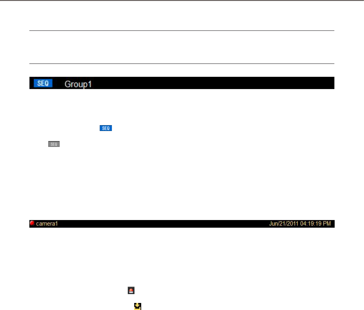
40
41
Group information display area
Note:
When the setting is configured to automatically display live images from the camera in which an alarm oc-•
curred, the group information display area will not be displayed while displaying live images from this cam-
era.
n [SEQ]
Indicates that the sequence display is being per-
formed currently. When the sequence display is being
performed, the indication will be displayed.
When the sequence display is being paused, the indi-
cation will be displayed. This indication will not
be displayed when the group display is being per-
formed.
n Group title
The group title will be displayed.
Camera information display area
n REC indicator/Alarm indicator/Buffering indica-
tor
These indicators will light when the images currently
being displayed are being recorded. When the setting
is configured to automatically display live images from
the camera in which an alarm occurred, the REC indi-
cator will turn to the alarm indicator .
When playing images on ASR500 and images are
being buffered, the buffering indicator will be dis-
played.
n Camera name
The camera title will be displayed.
n Time & date
Time & date will be displayed. When this software is
configured to display live images directly from the
camera in which an alarm occurred at an alarm occur-
rence, descriptions of the alarm will be displayed
instead of time & date. The time & date will be fol-
lowed by an asterisk "*" when the daylight saving time
is applied.
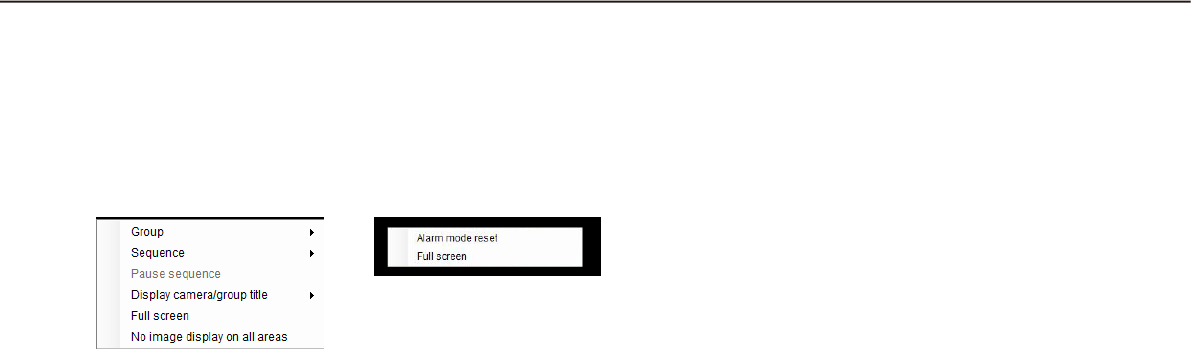
42
43
Pop-up menu
When right-clicking on the image display area, the pop-up menu will be displayed. There are two types of the
pop-up menus as follows.
n Group
Select a group to be displayed in the live image dis-
play area from the submenu.
n Sequence
Select a sequence to be displayed in the live image
display area from the submenu.
n Pause sequence/Resume sequence
Select to pause or resume the sequence display.
"Pause sequence" is available during the sequence
display and "Resume sequence" is available during
pausing the sequence display. These menus will not
be displayed when the group display is being per-
formed.
n Display camera/group title
It is possible to display/hide the group information
display area and the camera information display area
by selecting "Group title" or "Camera title" from the
submenu.
n Alarm mode reset
The alarm status will be reset.
n Full screen
The live image display area, the group information
display area and the camera information display area
will be displayed on a full screen.
n No image display on all areas
Clear the images displayed on all the areas.
During the group display
or the sequence display
During the live image display at an
alarm occurrence
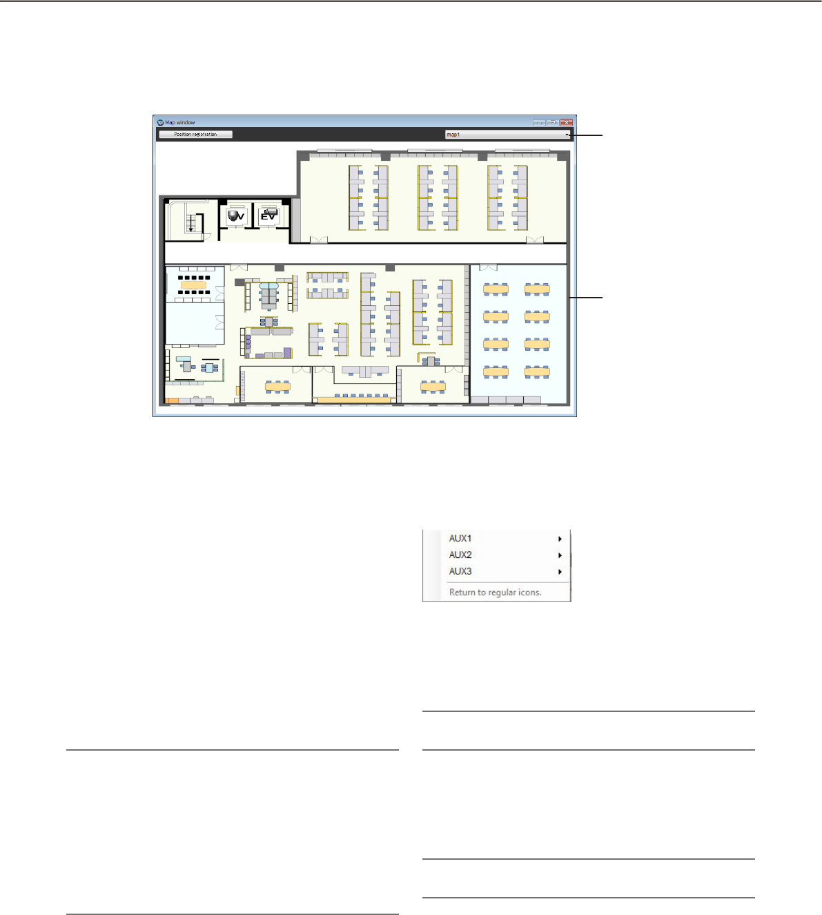
42
43
Map window
The following are descriptions about each item displayed on the map window.
n Map selection
Select a map.
n Map display area
The selected map will be displayed. The camera
icons and the map icons will be displayed on the
map.
n Position registration/Position registration
completion
Clicking the [Position registration] button can change
the icon positions.
The selected icon can move freely within the map.
Clicking the [Position registration completion] button
will register the new position.
Note:
Only an administrator can perform this operation.•
At an alarm or error occurrence during the posi-•
tion registration, the map display will not be
changed even when "ON" is selected for "Auto
change of map".
If the map window is closed without clicking the •
[Position registration completion] button, the new
positions will not be applied.
Pop-up menu
When right-clicking on the camera icon displayed on
the map, the pop-up menu will be displayed.
n AUX1
It is possible to select "Open" or "Close" from the sub
menu of the displayed pop-up menu for a device con-
nected to the AUX1 connector.
Note:
When using ASR500, AUX1 is not available.•
n AUX2
It is possible to select "Open" or "Close" from the sub
menu of the displayed pop-up menu for a device con-
nected to the AUX2 connector.
Note:
When using ASR500, AUX2 is not available.•
Map selection
Map display area

44
45
n AUX3
It is possible to select "Open" or "Close" from the sub
menu of the displayed pop-up menu for a device con-
nected to the AUX3 connector.
Note:
When using ASR500, AUX3 is not available.•
n Return to regular icons
The icon can be restored to the regular icon.
It is enabled when the camera connection is discon-
nected.
About the "Face Search" window
Refer to the following for further information about each item and the pop-up menu displayed on the "Face
Search" window.
"Check the alarm notification" (• ☞ page 83)
"Search the alarm notification" (• ☞ page 85)
"Search by person (face)" (• ☞ page 86)
"Display the statistical graphics of age/gender/head-count" (• ☞ page 92)
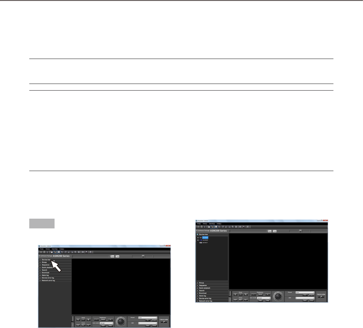
44
45
Monitor live images
Live images from up to 16 cameras can be displayed simultaneously on the operation monitor with use of this
software. It is not only possible to display live images from cameras connected to the same recorder, but also
from cameras connected to different recorders. It is also possible to display live images directly from the cam-
eras, not through the recorder.
It is possible to display live images from encoders or cameras that are not registered in the recorder.
Important:
Refer to the "Compatible devices" section (• + page 5) for further information about the models and the ver-
sions of devices compatible with this software.
Note:
Speed of image load may become slow when the processing load is too heavy on the devices or on the PC •
(such when many cameras are connected, when displaying live images from many cameras, etc.) or when
the network traffic is heavy.
When using the live window, images from up to 20 cameras can be displayed simultaneously. Refer to the •
"Operate using the multi-monitor function" section (+ page 59) for further information.
When network disconnection occurs while displaying live images, the images may sometimes not be dis-•
played correctly soon after recovery.
When the settings of the setup menu of the camera are edited while displaying live images, select the cam-
era again.
Confirm the registered devices
The devices registered in this software can be confirmed as follows.
Step 1
Click the "Device tree" bar on the function panel.
The "Device tree" panel will be displayed. The
registered devices will be displayed in the tree
view. When no device is registered, no device will
be displayed. Only an administrator can register
devices.
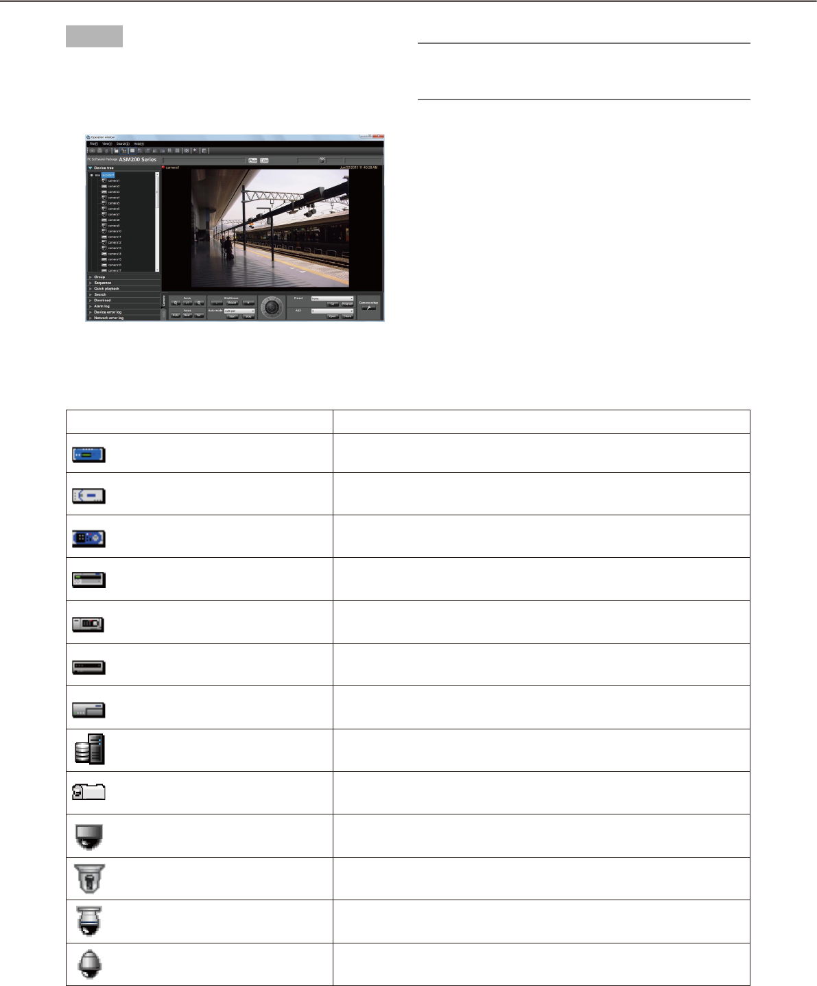
46
47
Icons in the device tree
The following are the descriptions of the icons displayed in the device tree.
Icon Description
ND300 (online)
ND200 (online)
HD300 (online)
ND400 (online)
HD600 (online)
NV200 (online)
Encoder (online)
ASR500 (online)
GXE100 Decoder (online)
Dome camera 1 (online)
Dome camera 2 (online)
Dome camera 3 (online)
Dome camera 4 (online)
Step 2
Double-click the recorder icon or the encoder icon or
click the [+] mark next to each device icon.
The icons of the cameras registered in the re-
corder or the encoder will be displayed.
Note:
Refer to the WV-ASM200 Setup Instructions (PDF) •
for how to register devices.
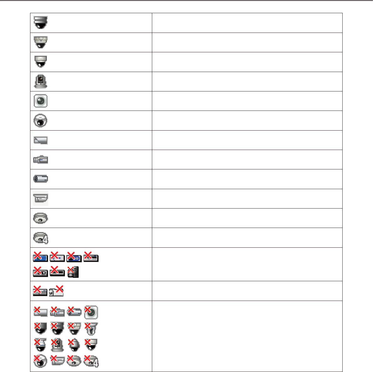
46
47
Dome camera 5 (online)
Dome camera 6 (online)
Dome camera 7 (online)
Dome camera 8 (online)
Dome camera 9 (online)
Dome camera 10 (online)
Stationary camera 1 (online)
Stationary camera 2 (online)
Stationary camera 3 (online)
Stationary camera 4 (online)
Fisheye camera 1 (online)
Fisheye camera 2 (online)
Recorder (offline)
Encoder (offline)
Offline cameras
When right-clicking on the camera icon, the pop-up menu will be
displayed. When "Return to regular icons." is selected, the camera
icon will indicate that the camera is online.
†1 Sometimes, live images may not be displayed even when the camera icon indicates that it is online. In this
case, the following are possible causes.
The Panasonic alarm protocol is not ready for reception. (The Panasonic alarm protocol notifi cation •
function is not active on the recorder, encoder and/or this software.)
The recorder is currently being confi gured using "HDD DISK MENU", or the SD memory recording is •
being performed.
†2 The icon status of a decoder will not turn to offline even after it is disconnected.
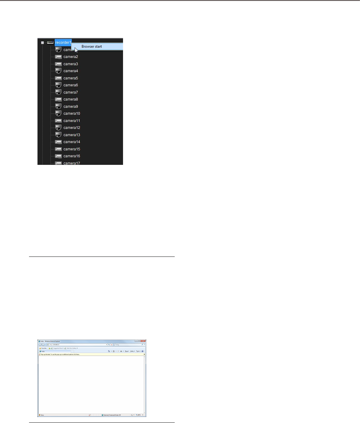
48
49
Pop-up menus over the icons in the device tree
When right-clicking on the camera icon, the pop-up menu will be displayed.
n Browser start
Start the web browser to display the top page of a
desired device. When the camera icon connected to
the recorder is selected, the device to be displayed
differ according to the method of video acquisition.
When the images are displayed through the recorder,
the top page of the recorder is displayed. When the
images are displayed through the camera, the top
page of the camera will be displayed.
Note:
These menus will be displayed only when the ad-•
ministrator or a user whose user level is "LV1"
logs into this software.
Depending on the settings of web browser, the •
top page may sometimes not be displayed due to
the pop-up blocker. In this case, cancel the pop-
up blocker on the following window.
When using ASR500, "Browser start" is not avail-•
able.
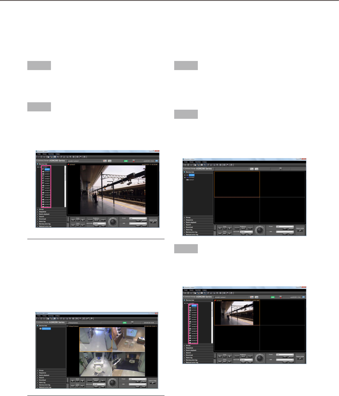
48
49
Monitor images from the selected camera
Click the desired camera icon. Images from the selected camera will be displayed. Images from the camera can
be displayed in various ways; display on a 1-screen, display in the desired area, display on a full screen, etc.
Monitor images on a 1-screen
Step 1
Select "Display images on 1-screen" under "Camera
selection(D)" under "View(V)" on the menu bar or click
the [Display images on 1-screen] icon on the tool bar.
Step 2
Click the desired camera icon when the image display
area is 1-screen.
Images from the selected camera will be dis-
played on a 1-screen.
Note:
When right-clicking on the image being played, •
the pop-up menu will be displayed. "Save as
JPEG file", "Print" and "EL-zoom" are also availa-
ble from the pop-up menu displayed by right-
clicking.
While "Quad PTZ" is selected for the image cap-•
ture mode of the Fisheye camera in use, 4-screen
display is available.
Specify the area to display images
Step 1
Select "Display images on the selected area(S)" under
"Camera selection(D)" under "View(V)" on the menu
bar or click the [Display images on the selected area]
icon on the tool bar.
Step 2
Click the desired area when displaying images on a
multi-screen (4/9/16).
The frame will be displayed around the selected area
to indicate the current selection.
Step 3
Click the desired camera icon.
Image from the selected camera will be displayed in
the selected area.
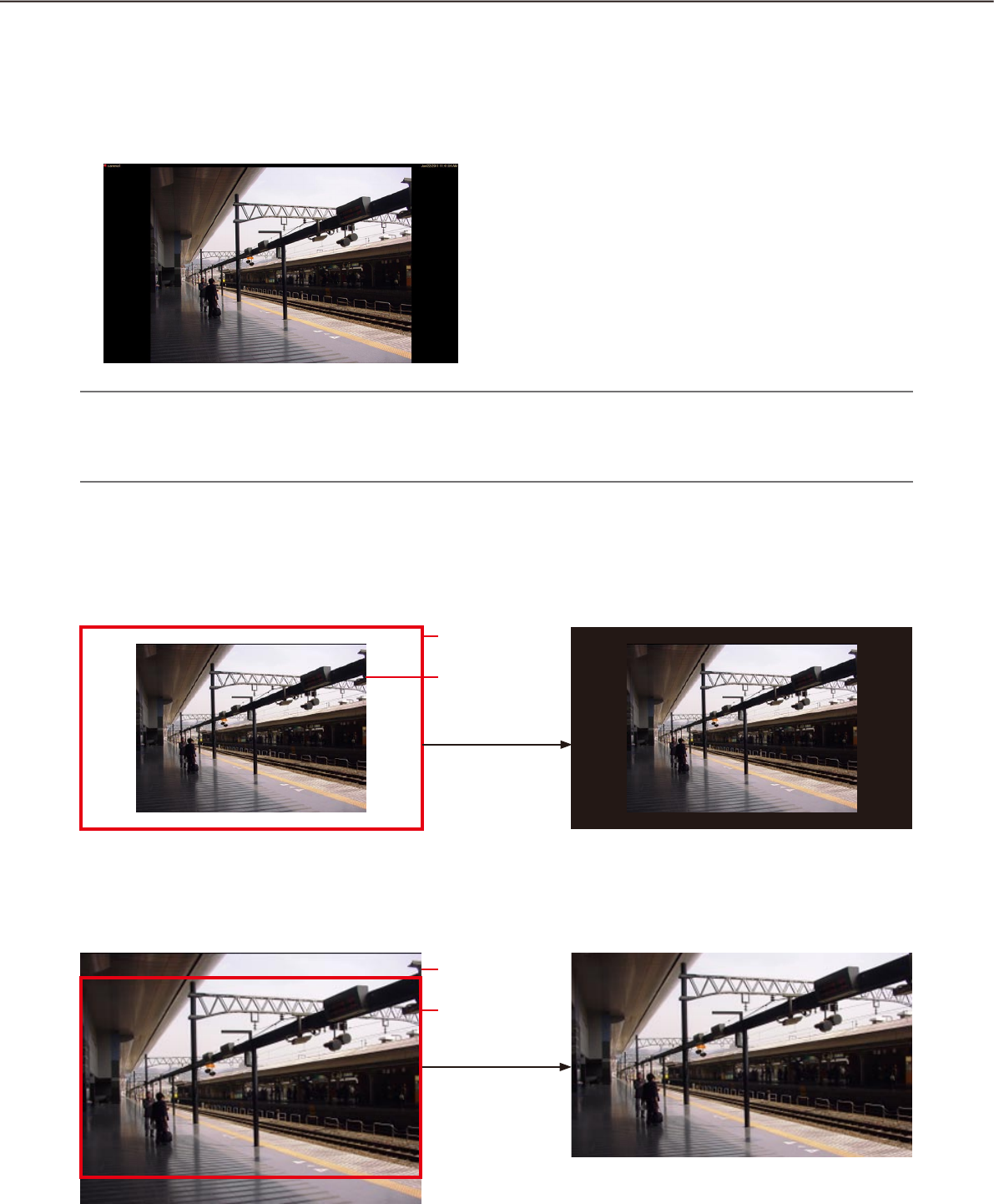
50
51
•Whenthedisplaywindowsizeissmallerthantheimagefromthecamera
•Whenthedisplaywindowsizeislargerthantheimagefromthecamera
Aspect ratio/Scaling mode
In the aspect ratio mode, images will be displayed in the selected area while keeping its aspect ratio. Black
bands will appear outside the displayed image.
The following are the examples when the aspect ratio of displayed images is 4:3.
Note:
Images from the HD300 will be enlarged/reduced even in the aspect ratio mode. In the scaling mode, the •
displayed images will be enlarged/reduced in the whole of the selected area.
Images from the ASR500 will be enlarged/reduced even in the aspect ratio mode.•
In the same size display mode, images will be displayed with the resolution specified on the camera.
Adjustment will be required between the resolution of the images from the camera and the display window size.
See the following example.
The whole image will be displayed and blank
space will be displayed in black.
Only the area of the image that can be displayed
in the display window area will be displayed.
Display window
size
Size of the image
from the camera
Display window
size
Size of the image
from the camera
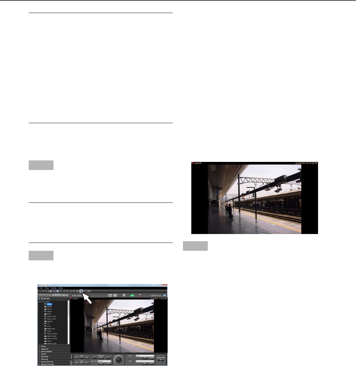
50
51
Step 1
Display live images.
Refer to the "Monitor live images" section ( ☞
page 45) for how to display live images.
Note:
It is also possible to display recorded images on a •
full screen. Playback on a full screen is available
only at normal playback speed (1x) and reverse
playback is unavailable.
Step 2
Select "Full screen(F)" under "View(V)" on the menu
bar or click the [Full screen] icon on the tool bar.
The image display area with the information dis-
play area will be displayed on a full screen.
Step 3
Full screen display will be canceled and will return to
the normal window size by selecting "Exit from the
full screen display" from the pop-up menu displayed
by right-clicking on the image displayed on a full
screen.
Monitor images on a full screen
Note:
When the display window size is smaller then the •
image from the camera, the area of the image that
is not displayed can be moved to the center of the
display area by click operation on the display
area. In this case, panning/tilting operation will be
performed together with this operation when using
the PTZ camera.
An image to be saved as a still image or an image •
to be printed will be output with the display win-
dow size.
This operation is available on 1-/4-/9-/16-screen. •
When operating on 25-/36-/49-/64-screen, the as-
pect ratio will be applied.
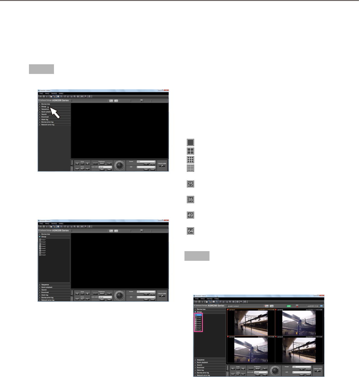
52
53
Display images from the cameras registered as a group
(group display)
It is possible to register multiple cameras as a group. When registering multiple groups, images from the cam-
eras can be displayed in group of the cameras.
Step 1
Click the "Group" bar on the function panel.
The "Group" panel will be displayed.
The name of the registered group and the group
icon that indicates the selected multi-screen will
be displayed.
n Registered group
The registered groups will be displayed in list form.
Only groups available for the login user will be dis-
played. Only an administrator can register the cam-
eras as groups. Refer to the WV-ASM200 Setup
Instructions (PDF) for further information.
n Group title
The group title will be displayed with the icon that
indicates the screen pattern selected to display the
respective group.
When clicking the icon, images from the selected
group will be displayed in the image display area with
the selected screen pattern.
The icon indicates the screen pattern as follows.
1-screen icon
4-screen icon
9-screen icon
16-screen icon
25-screen icon (Availlable after the license for
the WV-ASE202 is added)
36-screen icon (Availlable after the license for
the WV-ASE202 is added)
9-screen icon (Availlable after the license for
the WV-ASE202 is added)
64-screen icon (Availlable after the license for
the WV-ASE202 is added)
Step 2
Click the desired group icon.
Live images from the selected group will be dis-
played in the image display area.
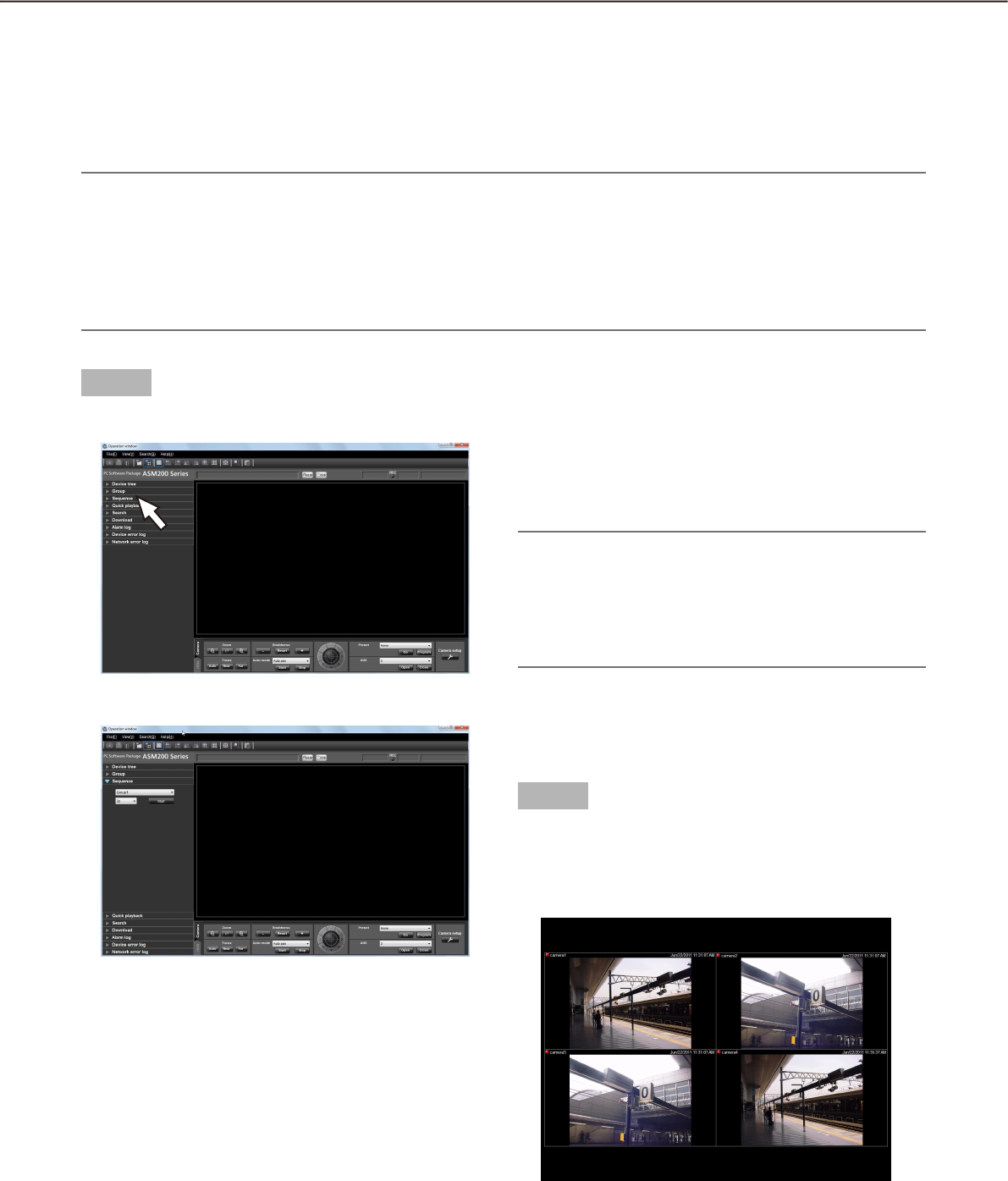
52
53
Step 1
Click the "Sequence" bar on the function panel.
The "Sequence" panel will be displayed.
n Sequence
Select the registered sequence from the drop-down
list. Only an administrator can register the sequence
using the setup software.
Refer to the WV-ASM200 Setup Instructions (PDF) for
further information.
Display images from the cameras registered as a group
sequentially (sequence display)
Images from the registered groups can be displayed on a full screen in an automatic sequential manner. It is
possible to set the dwell time (sequence interval) for the sequence display.
Note:
Actual dwell time may become longer than the set dwell time when the processing load is too heavy on the •
devices or on the PC (such when many cameras are connected, when displaying live images from many
cameras, etc.) or when the network traffic is heavy.
Images may sometimes not be displayed during the sequence display depending on the network environ-•
ment.
It is recommended to use less than 10 recorders when using the sequence display.•
n Sequence dwell time
Select the dwell time of the selected sequence from
the following.
3s/5s/10s/15s/20s/25s/30s/35s/40s/45s/50s/55s/
1min
Default: 3s
Note:
"Sequence dwell time" is the duration from the •
moment when completing displaying of all images
from the cameras registered as a group till the
moment when starting displaying images of the
next group.
n [Start] button
When this button is clicked, the sequence display will
start with the selected dwell time.
Step 2
Click the [Start] button after selecting the registered
sequence and the sequence dwell time.
The window will be switched to a full screen and
the sequence display will start.

54
55
Step 3
To stop the sequence display, select "Exit from the
full screen display" from the pop-up menu displayed
by right-clicking. When the sequence display is
stopped, the full screen will return to the normal win-
dow size and live image display will start. Live images
displayed after stopping the sequence display will be
of the group’s that have been displayed when the
sequence display is stopped.
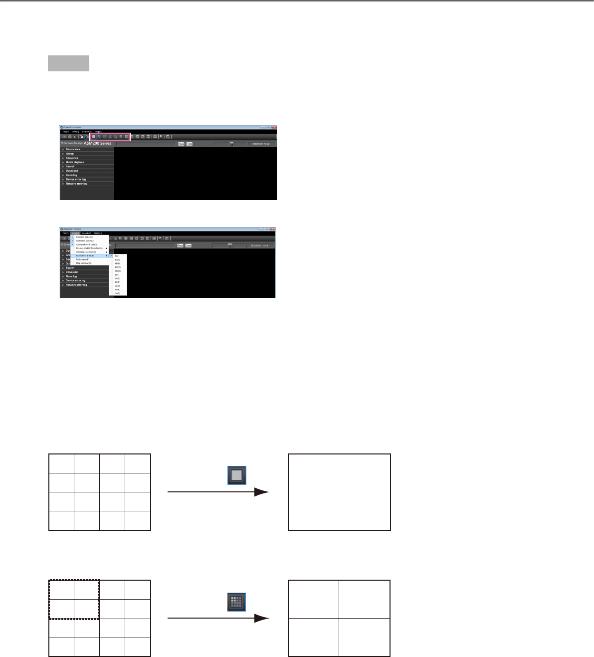
54
55
Switch the pattern of the screen
The following are the descriptions of how to switch the pattern of the screen (1/4/9/16/25/36/49/64) in the
image display area.
Step 1
Select "Number of area(S)" under "View(V)" on the
menu bar or click the desired icon ([1] - [64]) on the
tool bar.
The images will be displayed on the selected
screen pattern.
Submenu: 1(O)
Tool bar:
1
1
5
9
13
2
6
10
14
3
7
11
15
4
8
12
16
Double-click Double-click
1
11
5
9
13
2
6
10
14
3
7
11
15
4
8
12
16
1
1 2
5 6
5
9
13
2
6
10
14
3
7
11
15
4
8
12
16
Submenu: 4A(A)
Tool bar:
1
3 4
7 8
5
9
13
2
6
10
14
3
7
11
15
4
8
12
16
Submenu: 4B(B)
Tool bar:
1
9 10
13 14
5
9
13
2
6
10
14
3
7
11
15
4
8
12
16
Submenu: 4C(C)
Tool bar:
1
11 12
15 16
5
9
13
2
6
10
14
3
7
11
15
4
8
12
16
Submenu: 4D(D)
Tool bar:
1
5
9
13
2
6
10
14
31 2 3
5 6 7
9 10 11
7
11
15
4
8
12
16
Submenu: 9(N)
Tool bar:
Switch the screen pattern from 16-screen
When the screen pattern is switched from 16-screen to 1-screen, 4-screen or 9-screen, images to be displayed
will be as follows.
Group display on 16-screen Group display on 1-screen
Group display on 16-screen Group display on 4-screen
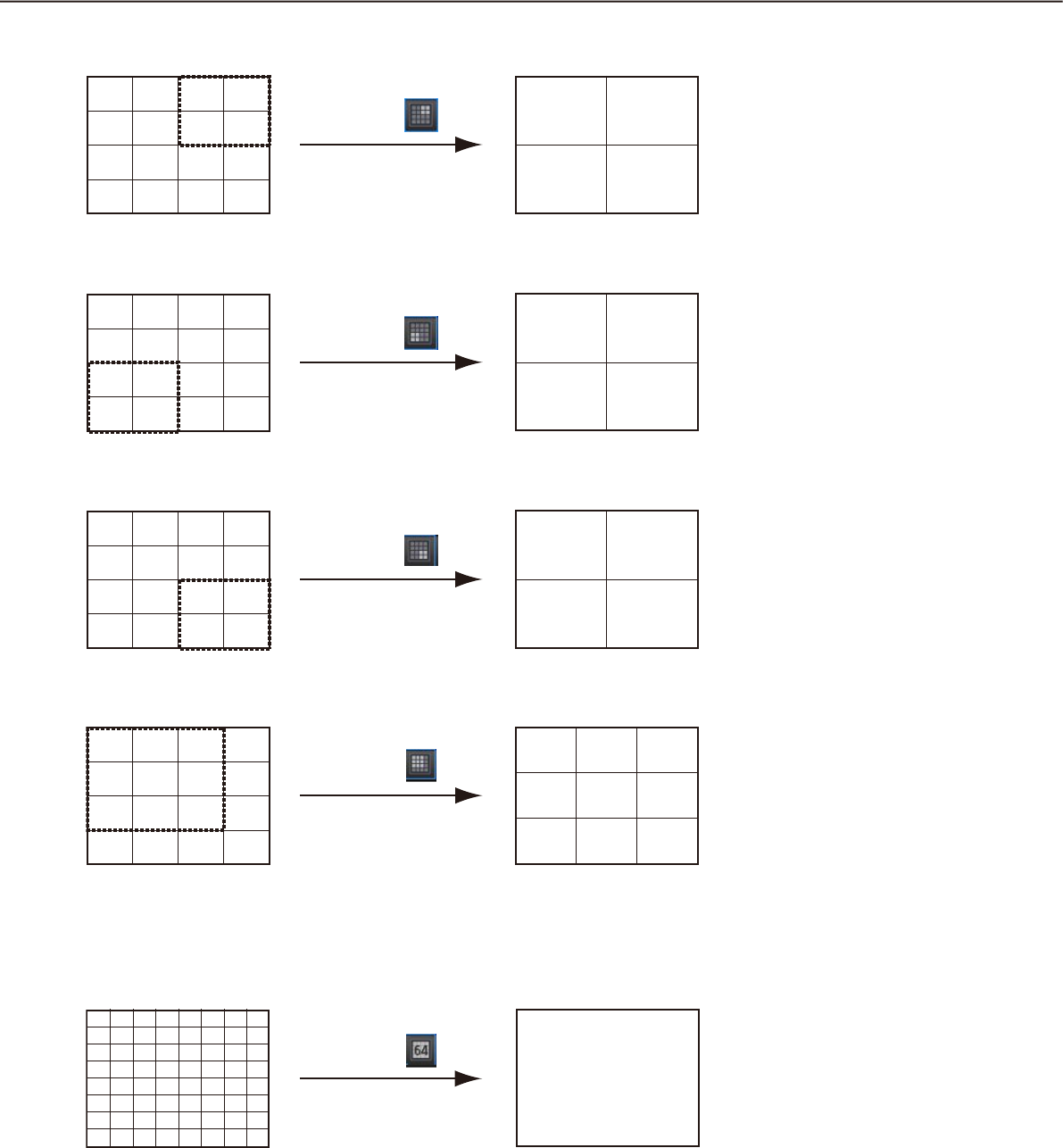
56
57
Group display on 16-screen Group display on 4-screen
Group display on 16-screen Group display on 4-screen
Group display on 16-screen Group display on 4-screen
Group display on 16-screen Group display on 9-screen
Submenu: 1(O)
Tool bar:
1
1
5
9
13
2
6
10
14
3
7
11
15
4
8
12
16
Double-click Double-click
1
11
5
9
13
2
6
10
14
3
7
11
15
4
8
12
16
1
1 2
5 6
5
9
13
2
6
10
14
3
7
11
15
4
8
12
16
Submenu: 4A(A)
Tool bar:
1
3 4
7 8
5
9
13
2
6
10
14
3
7
11
15
4
8
12
16
Submenu: 4B(B)
Tool bar:
1
9 10
13 14
5
9
13
2
6
10
14
3
7
11
15
4
8
12
16
Submenu: 4C(C)
Tool bar:
1
11 12
15 16
5
9
13
2
6
10
14
3
7
11
15
4
8
12
16
Submenu: 4D(D)
Tool bar:
1
5
9
13
2
6
10
14
31 2 3
5 6 7
9 10 11
7
11
15
4
8
12
16
Submenu: 9(N)
Tool bar:
When the screen pattern is switched from 64-screen to 1-screen, 4-screen, 9-screen, 16-screen, 25-screen,
36-screen or 49-screen, images to be displayed will be as follows.
Group display on 64-screen Group display on 1-screen
1
1
17
33
49
3
19
35
51
5
21
37
53
7
23
39
55
9
25
41
57
11
27
43
59
13
29
45
61
15
31
47
63
2
18
34
50
4
20
36
52
6
22
38
54
8
24
40
56
10
26
42
58
12
28
44
60
14
30
46
62
16
32
48
64
Submenu: 1(O)
Tool bar:
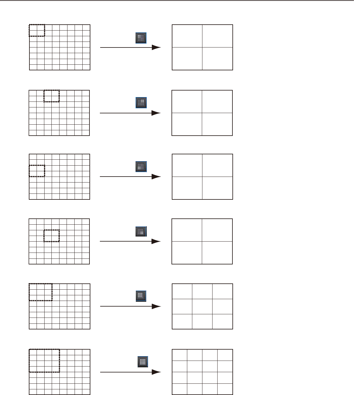
56
57
Group display on 64-screen Group display on 4-screen
Group display on 64-screen Group display on 4-screen
Group display on 64-screen Group display on 4-screen
Group display on 64-screen Group display on 4-screen
Group display on 64-screen Group display on 9-screen
Group display on 64-screen Group display on 16-screen
1 2
9 10
1
17
33
49
3
19
35
51
5
21
37
53
7
23
39
55
9
25
41
57
11
27
43
59
13
29
45
61
15
31
47
63
2
18
34
50
4
20
36
52
6
22
38
54
8
24
40
56
10
26
42
58
12
28
44
60
14
30
46
62
16
32
48
64
Submenu: 4A(A)
Tool bar:
3 4
11 12
1
17
33
49
3
19
35
51
5
21
37
53
7
23
39
55
9
25
41
57
11
27
43
59
13
29
45
61
15
31
47
63
2
18
34
50
4
20
36
52
6
22
38
54
8
24
40
56
10
26
42
58
12
28
44
60
14
30
46
62
16
32
48
64
Submenu: 4B(B)
Tool bar:
17 18
25 26
1
17
33
49
3
19
35
51
5
21
37
53
7
23
39
55
9
25
41
57
11
27
43
59
13
29
45
61
15
31
47
63
2
18
34
50
4
20
36
52
6
22
38
54
8
24
40
56
10
26
42
58
12
28
44
60
14
30
46
62
16
32
48
64
Submenu: 4C(C)
Tool bar:
19 20
27 28
1
17
33
49
3
19
35
51
5
21
37
53
7
23
39
55
9
25
41
57
11
27
43
59
13
29
45
61
15
31
47
63
2
18
34
50
4
20
36
52
6
22
38
54
8
24
40
56
10
26
42
58
12
28
44
60
14
30
46
62
16
32
48
64
Submenu: 4D(D)
Tool bar:
1 2 3
9 10 11
17 18 19
1
17
33
49
3
19
35
51
5
21
37
53
7
23
39
55
9
25
41
57
11
27
43
59
13
29
45
61
15
31
47
63
2
18
34
50
4
20
36
52
6
22
38
54
8
24
40
56
10
26
42
58
12
28
44
60
14
30
46
62
16
32
48
64
Submenu: 9(N)
Tool bar:
1
9
17
25
2
10
18
26
3
11
19
27
4
12
20
28
1
17
33
49
3
19
35
51
5
21
37
53
7
23
39
55
9
25
41
57
11
27
43
59
13
29
45
61
15
31
47
63
2
18
34
50
4
20
36
52
6
22
38
54
8
24
40
56
10
26
42
58
12
28
44
60
14
30
46
62
16
32
48
64
Submenu: 16(S)
Tool bar:
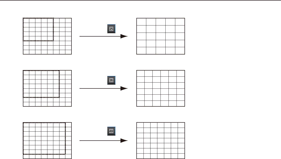
58
59
Group display on 64-screen Group display on 25-screen
Group display on 64-screen Group display on 36-screen
Group display on 64-screen Group display on 49-screen
109 11 12 13
21 3 4 5
1817 19 20 21
2625 27 28 29
3433 35 36 37
1
17
33
49
3
19
35
51
5
21
37
53
7
23
39
55
9
25
41
57
11
27
43
59
13
29
45
61
15
31
47
63
2
18
34
50
4
20
36
52
6
22
38
54
8
24
40
56
10
26
42
58
12
28
44
60
14
30
46
62
16
32
48
64
Submenu: 25(P)
Tool bar:
109 11 12 13 14
1817 19 20 21 22
2625 27 28 29 30
3433 35 36 37 38
4241 43 44 45 46
21 3 4 5 6
1
17
33
49
3
19
35
51
5
21
37
53
7
23
39
55
9
25
41
57
11
27
43
59
13
29
45
61
15
31
47
63
2
18
34
50
4
20
36
52
6
22
38
54
8
24
40
56
10
26
42
58
12
28
44
60
14
30
46
62
16
32
48
64
Submenu: 36(H)
Tool bar:
109 11 12 13 14 15
1817 19 20 21 22 23
2625 27 28 29 30 31
3433 35 36 37 38 39
4241 43 44 45 46 47
5049 51 52 53 54 55
21 34567
1
17
33
49
3
19
35
51
5
21
37
53
7
23
39
55
9
25
41
57
11
27
43
59
13
29
45
61
15
31
47
63
2
18
34
50
4
20
36
52
6
22
38
54
8
24
40
56
10
26
42
58
12
28
44
60
14
30
46
62
16
32
48
64
Submenu: 49(E)
Tool bar:
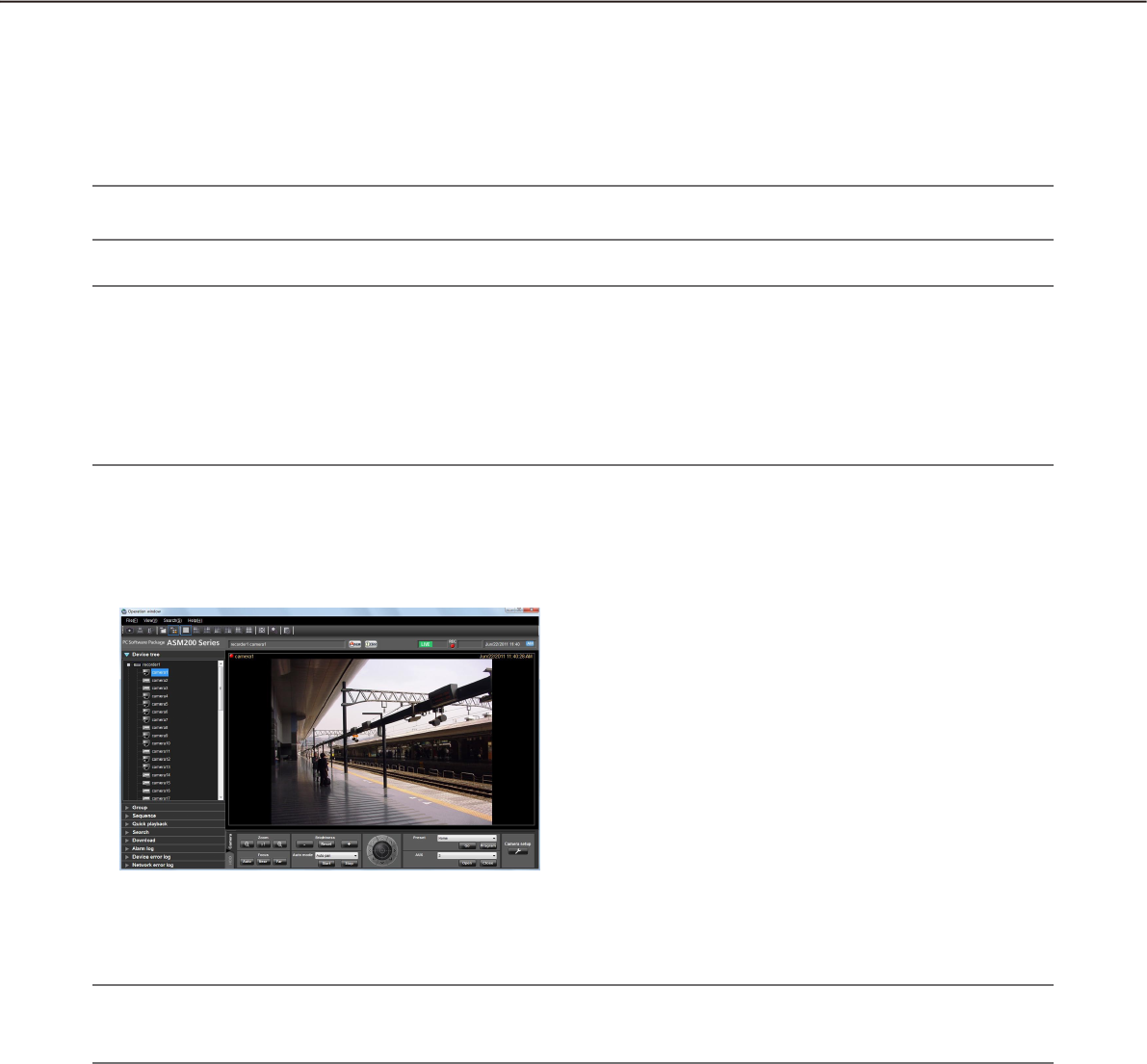
58
59
Operate using the multi-monitor function
The multi-monitor function using up to 3 PC monitors is available, and it is possible to display the operation
window, the live window and the map window simultaneously.
After the license for the WV-ASE202 is added, the multi-monitor function using up to 6 PC monitors will
become available, and it will become possible to display the operation window, the map window and the 4 map
windows simultaneously.
Important:
It is necessary to register the license for the Extension Software WV-ASE201.•
Note:
The maximum number of areas (multi-screen pattern) of the operation window and the live window can be •
determined on the setup software. Refer to the WV-ASM200 Setup Instructions (PDF) for further information.
Up to 16 areas (16-screen) can be displayed for the sequence display.•
When the port setting of the camera is stationary, live images will be displayed either on the operation win-•
dow or the live window. Refer to the operating instructions of the camera for how to configure the settings
for MPEG-4 transmission.
Operate the operation window
On the operation window, all operations relating to the live image display, playback and the sequence display
are available.
Note:
A black screen may sometimes be displayed when keeping on clicking around the edge of the screen to en-•
large MPEG-4 or H. 264 images using the EL-zoom function.
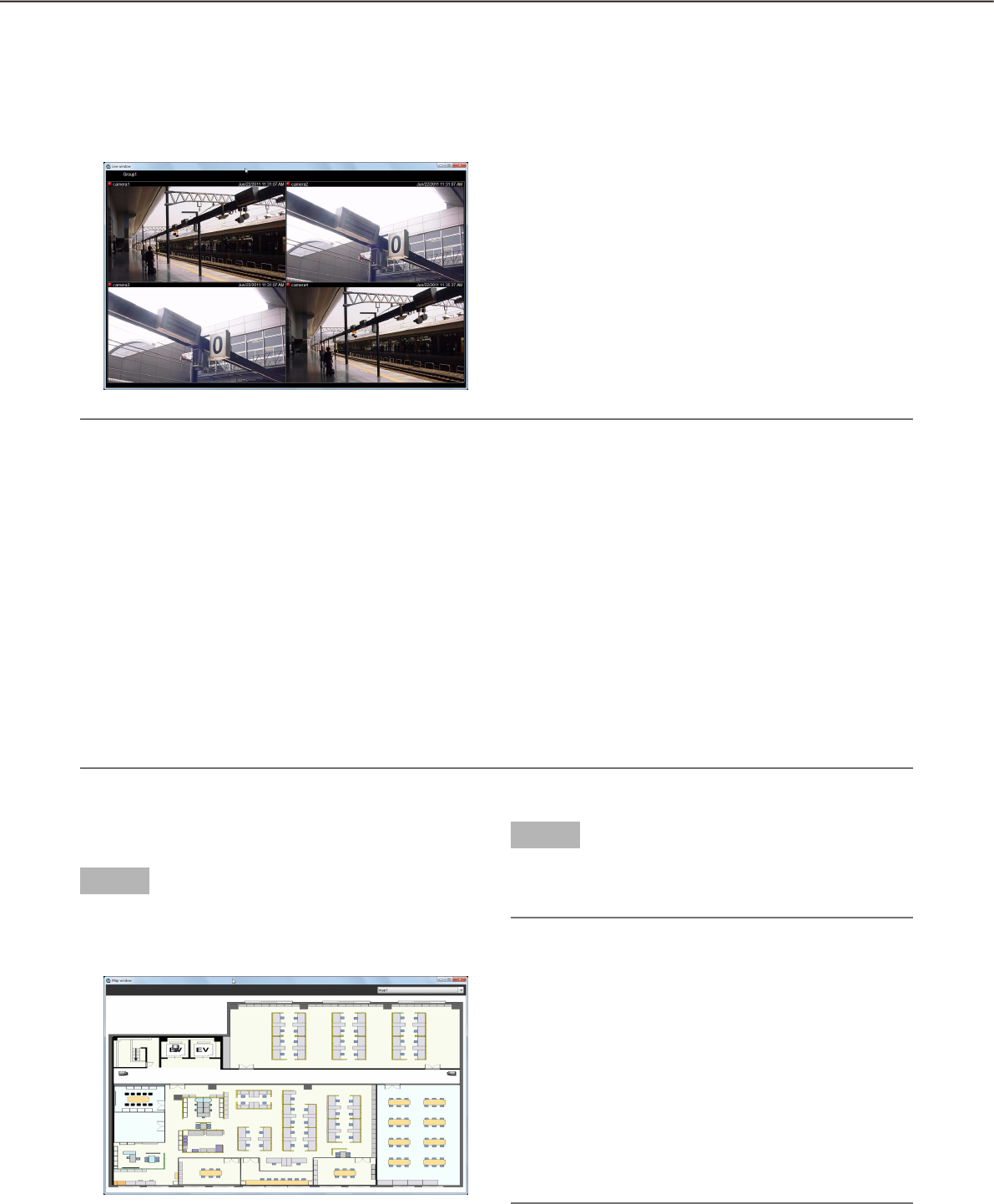
60
61
Note:
Right-clicking on the live window provides the pop-up menu. •
Refer to "Live window" (+ page 40) for further information.
When adding the license for the WV-ASE202 to display more than one live window, it is necessary to select •
"Live window(L)..." under "View(V)" on the menu bar repeatedly.
When displaying the images of more than one live window (it is necessary to add the license for the WV-•
ASE202), the display order will be Live window (1) Live window (2) Live window (3) Live window (4).
If the live window display is canceled on the way, the images of live window with the smallest number after
cancellation will be displayed next time.
When displaying the images of more than one live window (it is necessary to add the license for the WV-•
ASE202) or when the maximum number of areas for the live window is set to 25-screen or more, it may take
some time until the live windows are displayed.
When displaying the images of more than one live window (it is necessary to add the license for the WV-•
ASE202) by using two video cards, run on Windows Vista or Windows 7 and turn off the Aero feature. When
running on Windows 8, this function is not guaranteed to work since the Aero feature can not be turned off
on Windows 8.
Operate the live window
On the live window, operations relating to the live image display of group and the sequence display are avail-
able.
Select "Live window(L)..." under "View(V)" on the menu bar to display the live window.
Operate the map window
Step 1
Select "Map window(M)..." under "View(V)" on the
menu bar to display the map window.
The map window will be displayed.
Step 2
Map selection
Select the desired map from the drop-down list.
Note:
When the camera icon on the map is clicked, live •
images from the selected camera will be dis-
played in the selected area on the operation win-
dow.
When a map icon displayed on the map is clicked, •
the respective map will be displayed on the map
window.
When right-clicking on the camera icon displayed •
on the map, the pop-up menu will be displayed.
It is possible to select "Open" or "Close" from the
sub menu of the displayed pop-up menu for a de-
vice connected to the AUX connector.
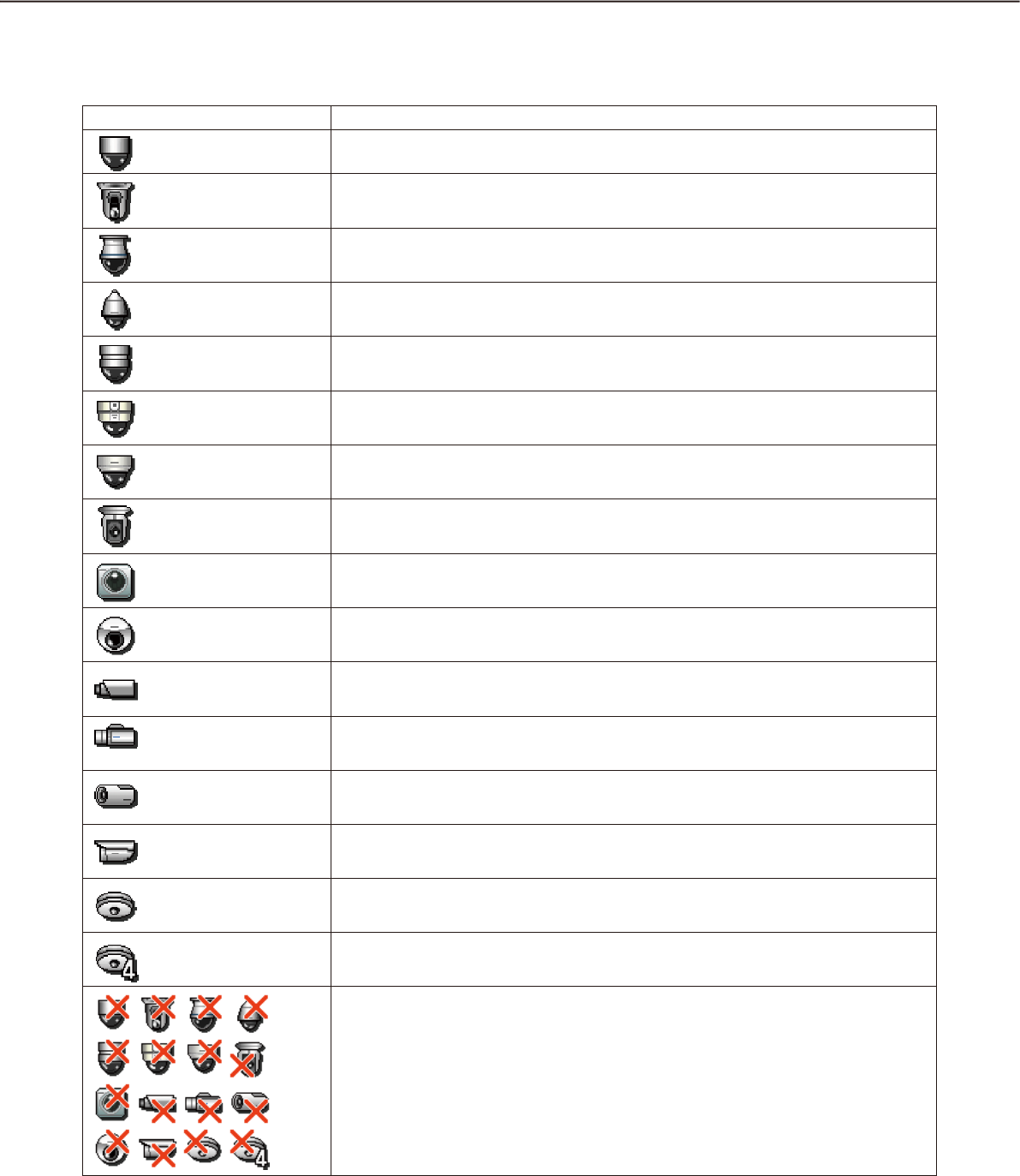
60
61
Icons on the map
The following are the descriptions of the icons displayed on the map.
Icon Description
Dome camera 1 (online)
Dome camera 2 (online)
Dome camera 3 (online)
Dome camera 4 (online)
Dome camera 5 (online)
Dome camera 6 (online)
Dome camera 7 (online)
Dome camera 8 (online)
Dome camera 9 (online)
Dome camera 10 (online)
Stationary camera 1 (online)
Stationary camera 2 (online)
Stationary camera 3 (online)
Stationary camera 4 (online)
Fisheye camera 1 (online)
Fisheye camera 2 (online)
Offline cameras
When right-clicking on the camera icon, the pop-up menu will be displayed.
When "Return to regular icons." is selected, the camera icon will indicate that the
camera is online.

62
63
Cameras in the alarm status
The icon will blink for 10 seconds after receiving an alarm.
When the icon is clicked, the icon will indicate that the camera is online.
Map
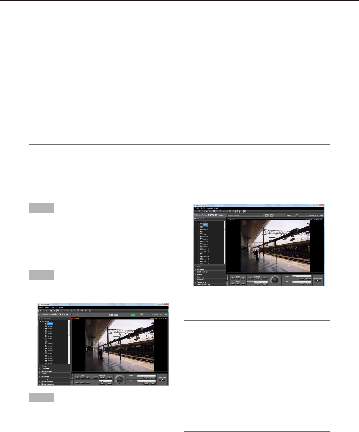
62
63
Operate the cameras
It is possible to operate the camera while displaying live images.
Some models may not be operable. Refer to the "Compatible devices" section (+ page 5) for the devices com-
patible with this software.
This software can operate the following.
•Panning/tilting†1: Adjusts the horizontal/vertical position of the displayed image.
•Zoom†3: Zooms in/out the displayed image.
•Focus†2: Adjusts the focal point of the displayed image.
•Brightness†2: Adjusts the lens iris.
•Presetfunction†1†4: Moves the camera to the preset position registered in advance. Registration of the
preset positions is also available.
•Automode†1†2: Starts the selected auto function.
•AUX†2: Selects "Open" or "Close" for the status of a device connected to the AUX connector.
†1 Available for PTZ cameras and Fisheye cameras
†2 When using ASR500, this function is unavailable regardless of the camera model.
†3 When using ASR500, [x1] button is not available.
†4 When using ASR500, [Go] button and [Program] button for the preset position "Home" are not available.
Note:
Some functions may be unavailable depending on the model of the camera. Contact your dealer for further •
information.
When using a camera registered for camera categories of NV200 with this software, some operations may •
be restricted depending on the model of the camera. When using NV200, register the camera on "Easy
start".
Step 1
Display live images.
Refer to the "Monitor live images" section for how to
display live images (+ page 45). When displaying
images on a multi-screen, click the desired area to
select the camera to be operated. The selected area
will be displayed with the frame in orange.
Step 2
Click the [Camera] tab.
The camera operation panel will be displayed.
Step 3
Operate the camera using the buttons on the camera
operation panel.
Refer to the "Camera operation panel" section ( +
page 29) for further information about the buttons
on the camera operation panel.
Note:
When the camera is being operated by a user •
whose user level is higher, this camera is unavail-
able to operate until this user stops operation of
this camera.
It is possible to pan/tilt the camera by clicking a •
point on the image display area.
Zooming is available using the wheel on the wheel •
mouse.
When specifying the area to display images by •
dragging the mouse, the camera will move to the
position centered around the specified area. In
this case, the zoom ratio will be automatically ad-
justed.
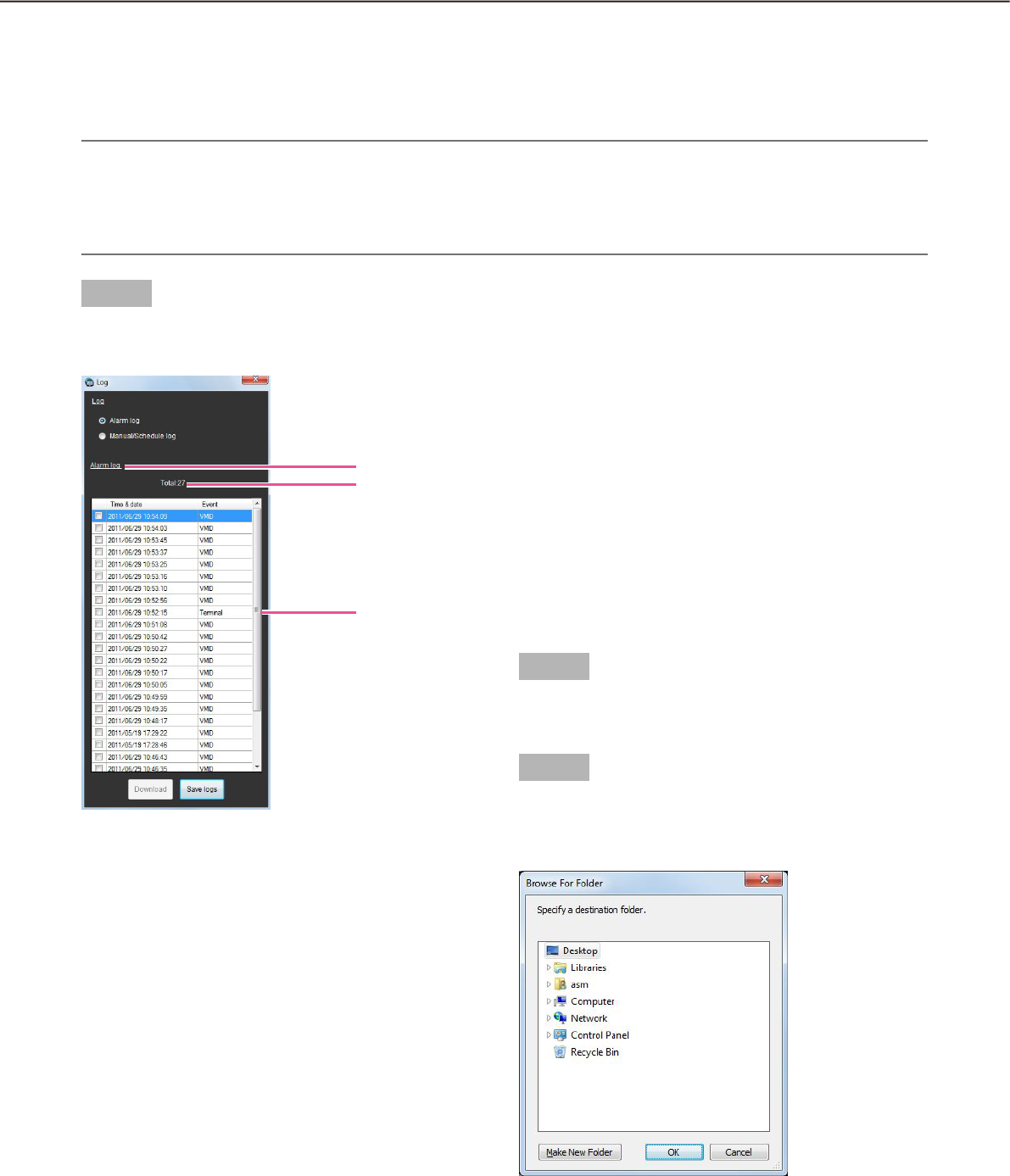
64
65
Operation of SD memory card
Download recorded images
While displaying live images, download H.264 video files (mp4 files) from the SD memory card in the registered
camera onto the PC. FTP function is used to download video files.
Note:
When two or more alarms occurred in the same file, they will be displayed on different log lists, but the •
same file will be downloaded.
Video data will be saved in a file whose size is approx. 2 MB. Data which exceeds 2 MB will be saved sepa-•
rately in two or more files to be downloaded.
Step 1
Display the log list window from the SD operation
panel.
The details are as follows.
n Alarm log
It is possible to check the time & date and the cause
of the alarm occurrence.
n Manual/Schedule log
It is possible to check the logs saved when images
are saved on the SD memory card manually or
according to the schedule setting.
n Select log type
Indicates which of the alarm logs or manual/schedule
logs are being displayed on the list.
n Number of the listed logs
Indicates the total number of the listed logs.
n Time & date
Indicates the time & date on which the logs were
filed.
n Event
Indicates the cause of the alarm occurrence. This
item will be displayed only for the alarm log list.
Terminal: Alarm by alarm input to Terminal 1
Terminal2: Alarm by alarm input to Terminal 2
Terminal3: Alarm by alarm input to Terminal 3
VMD: Alarm by VMD alarm
Command: Alarm by command alarm
n [Save logs] button
Saves the log list onto the PC.
Step 2
Select the list to download from the log list. Multiple
selection of the list is available.
Step 3
Click the [Download] button.
The window for a folder designation will be dis-
played.
Select log type
Number of the
listed logs
Log
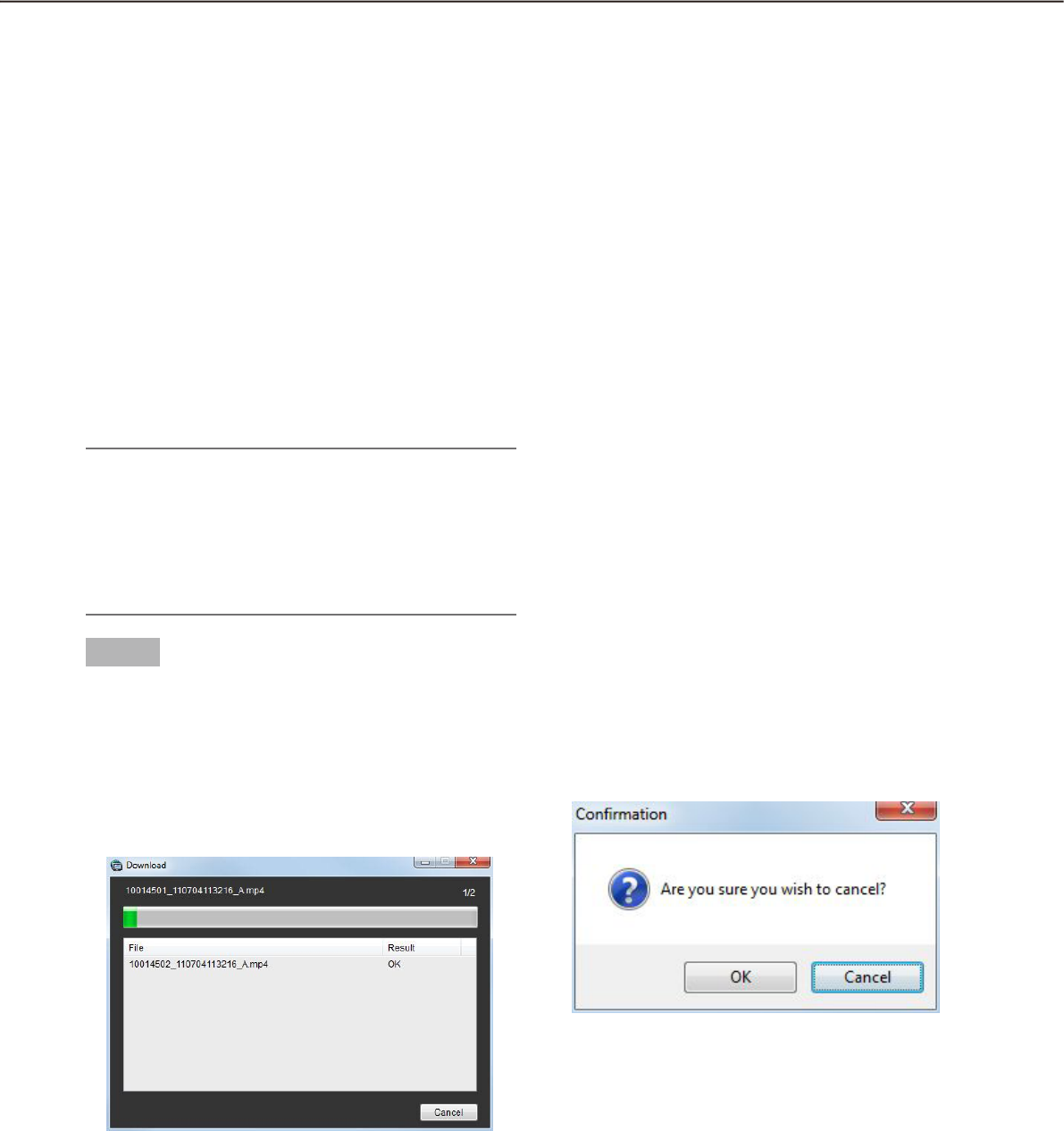
64
65
The details are as follows.
n Destination folder
Specify a folder as the destination of downloaded
files.
n [Make New Folder(M)] button
Create a new folder in the folder currently selected.
n [OK] button
Close the window for a folder designation do start
download.
n [Cancel] button
Close the window for a folder designation do cancel
download.
Note:
The overwrite warning window will be displayed •
when a file of the same name already exists in the
folder. If you do not wish to overwrite the existing
file, cancel download and select another folder.
It is impossible to click the [Download] button •
when no list is selected.
Step 4
Click the [OK] button after specifying a folder.
Download will start and the "Download" window
will be displayed. To cancel download, click the
[Cancel] button or the [×] button at the top right of
the window.
Downloaded files will be stored in the specified
folder.
The details are as follows.
n Name of the file currently being downloaded
Name of the file currently being downloaded will be
displayed.
n Number of files
"Number of files downloaded"/"Number of files to be
downloaded" will be displayed.
n Progress bar
The status of the download will be displayed.
n List of files
Information of the downloaded files will be displayed
in list form.
File: Downloaded files will be displayed.
Result: The status of the download file will be dis-
played.
OK: Download of the file is successfully completed.
NG: Download of the file failed.
n [OK] button/[Cancel] button
The [OK] button will be displayed when the download
is completed. The [Cancel] button will be displayed in
the process of download. When the [OK] button is
clicked, the "Download" window will close. When the
[Cancel] button is clicked in the process of download,
the download will be canceled.
If the download is canceled, the confirmation window
to cancel download will be displayed.
When the [OK] button is clicked, download will be
canceled. When the [Cancel] button is clicked, down-
load will continue.

66
67
Step 5
When the download is completed, click the [OK] but-
ton.
The download window will close.
Note:
When trying to exit this software or log out of the •
software during download, the download will be
automatically cancelled.
About the downloaded files
It is possible to play video data saved on the PC using such an application as QuickTime® Player or Windows
Media® Player*. However, we are not liable for performance relating to these applications.
* The supported operating system is Windows 7 only.
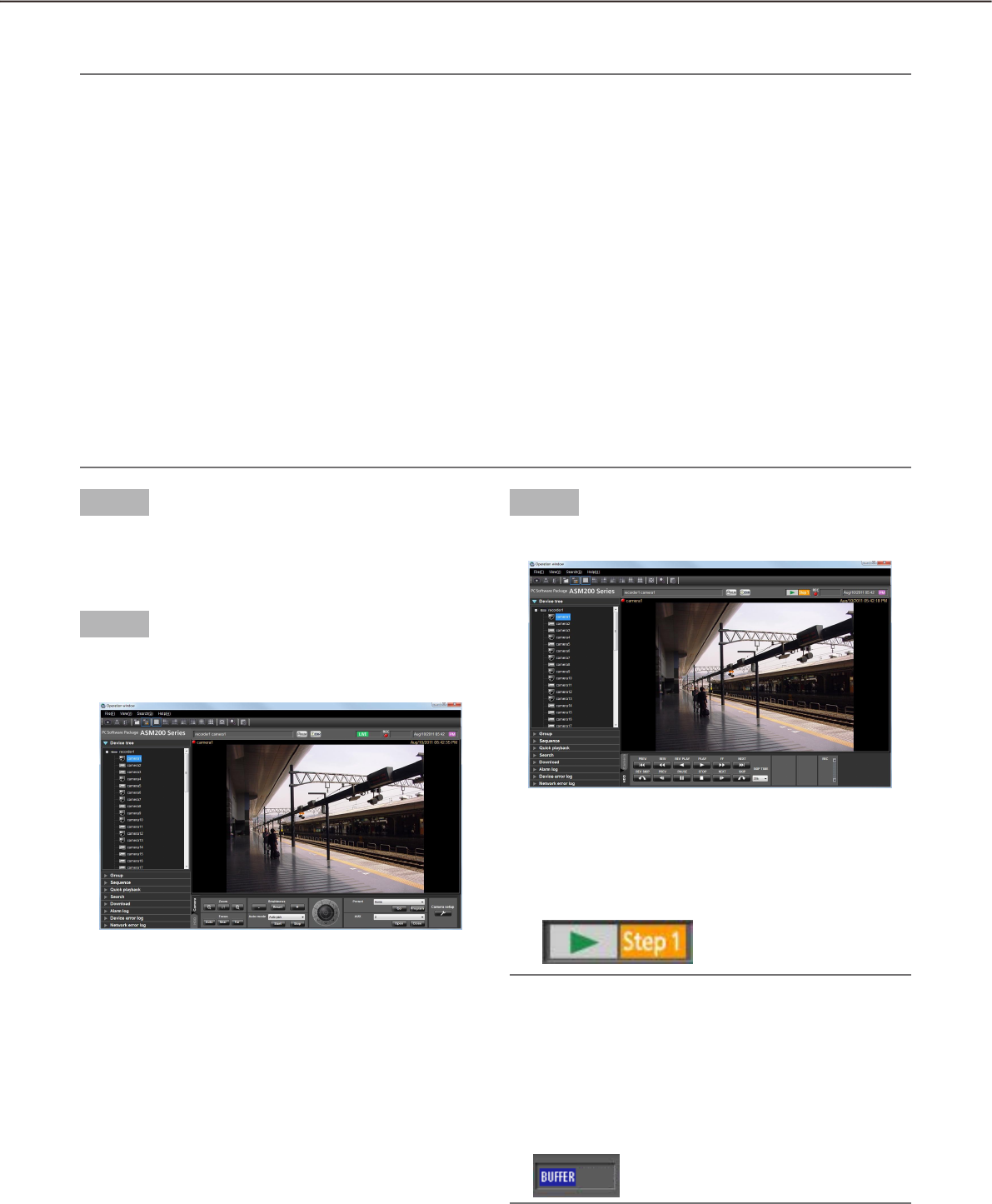
66
67
Playback
It is possible to play recorded images stored on the recorder using the operation window of this software.
Note:
Speed of image load may become slow when the processing load is too heavy on the recorder or on the PC •
(such when many cameras are connected, when displaying many recorded images, etc.) or when the net-
work traffic is heavy.
When playing recorded images on a multi-screen, sometimes the recording time synchronization of the dis-•
played recorded images may not be performed.
Recorded audio can be played depending on recorder model.•
Audio will be output only when playing images forward at 1x speed.•
Audio may be interrupted depending on the network environment.•
The video output may sometimes be ahead of the audio output.•
When there is no image recorded by the selected camera, a black screen will be displayed.•
When displaying and playing images from a camera that is not registered in the recorder, a black screen will •
be displayed.
Even after the license for the WV-ASE202 is added and while live images are being displayed on a •
25-screen or more, the maximum number of areas (multi-screen pattern) will become 16-screen after re-
corded images are displayed.
When playing recorded images using ASR500, • due to image buffering, the image refresh interval may be-
come 1 second or playback may pause regardless of the frame rate specified for recording.
Step 1
Display live images.
Refer to the "Monitor live images" section ( +
page 45) for how to display live images.
Step 2
Click the [HDD] tab.
The playback operation panel will be displayed.
Step 3
Click the [PLAY] button.
Playback image will be displayed in the image
display area where live images are being dis-
played. The live indication displayed in the infor-
mation display area will turn to the playback
indication.
Note:
Playback will start from the latest recorded image.•
When using ASR500, playback will be performed •
while buffering recorded images. In the state of
buffering, the following status will be displayed.
The image refresh interval may become 1 second
or playback may pause while this status is being
displayed.

68
69
Step 4
To stop playback, click the [STOP] button.
Live images will be displayed in the image display
area where playback images are being displayed.
The playback indication displayed in the informa-
tion display area will turn to the live indication.
Note:
Operate the playback images using the buttons •
on the playback operation panel. Refer to the
"Playback operation panel" section (+ page 32)
for further information about the buttons on the
playback operation panel.
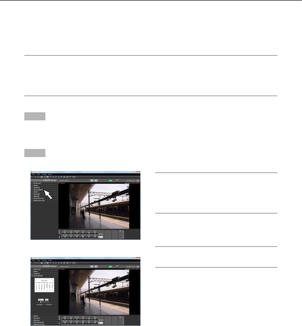
68
69
Play images using the "Quick playback" panel
Search and playback of recorded images can be easily performed when using the "Quick playback" panel.
There are three ways to play recorded images as follows.
Play recorded images from the search result list displayed after searching by designating the recording time•
Play recorded images from the search result list displayed after searching by designating the time & date of •
SD memory data
Play the latest recorded image•
Note:
When displaying images on a multi-screen, playback images will be displayed in all areas.•
It is impossible to play SD memory data on a multi-screen.•
When the SD memory data contains not many frames, playback may sometimes not be performed in a nor-•
mal manner. (A black screen may be displayed, or speed of image load may become slow, etc.) In this case,
display the image with frame playback/ reverse frame playback.
Step 1
Display live images from the recorder to be searched.
Refer to the "Monitor live images" section ( +
page 45) for how to display live images.
Step 2
Click the "Quick playback" bar on the function panel.
The "Quick playback" panel will be displayed.
The following are descriptions about each item dis-
played on the "Quick playback" panel.
n Calendar/time
Select time & date from "Jan/01/2005" -
"Dec/31/2034".
Select a number for hour from "AM12" - "PM11".
Select a number for minute (1 minute step).
Note:
When the software in use is European specifica-•
tion, select the time & date from the following.
Date: Between "01/01/2005" and "31/12/2034"
Hour: Between "0" and "23"
Minute: Between "00" and "59" (1 minute step)
n SD memory rec.
Check this checkbox to search for recorded images
from the SD memory data.
Note:
When displaying images on a multi-screen, it is •
impossible to check the checkbox.
n [Go to date] button
Click this button to start playback of images recorded
at the selected time & date.
n [Go to last] button
Click this button to start playback of the latest
recorded images.
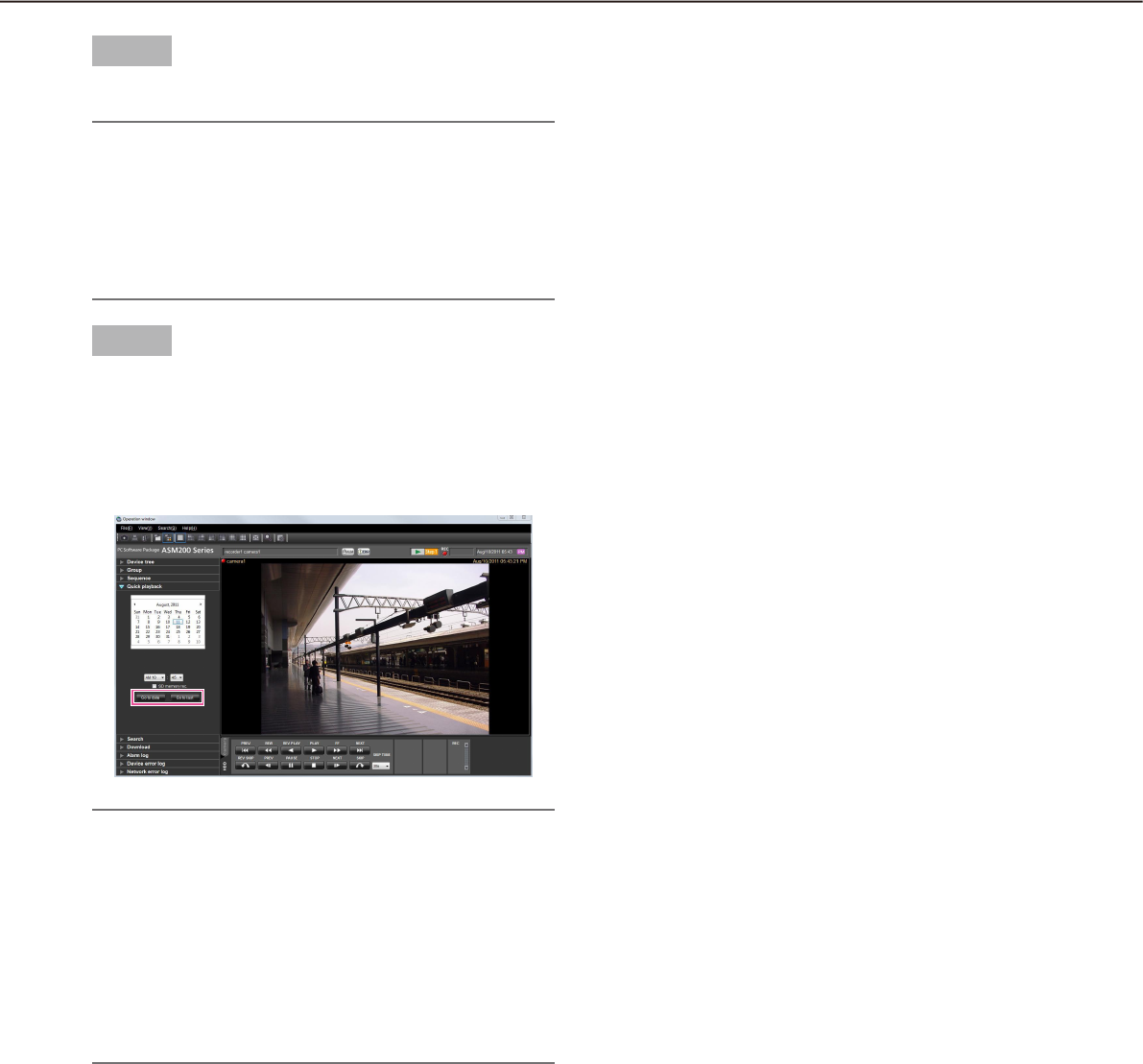
70
71
Step 3
Select the desired time & date.
Note:
It is unnecessary to designate the time & date •
when playing the latest recorded image. The latest
recorded image to be played is determined ac-
cording to the setting of the recorder. Refer to the
operating instructions of the recorder in use for
further information.
Step 4
Click the [Go to date] button or the [Go to last] but-
ton.
Images recorded at the selected time & date or
the latest recorded image will be played in the
image displayed area.
Note:
When playing MPEG-4 or H.264 images, playback •
may start from a point several seconds after the
designated time & date. Sometimes, playback
may start from the beginning of the next record.
When playback cannot be performed correctly •
even when designating the time & date of the SD
memory data to be searched, it may be possible
that there is no image recorded by the SD mem-
ory recording.
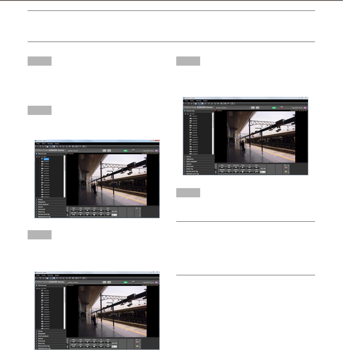
70
71
Start/stop recording manually
Note:
To perform manual recording, login by the user with the level of manual recording and playing authorization •
is required.
Manual recording is not available when using ASR500.•
Step 1
Display live images from the recorder to be used for
recording.
Refer to the "Monitor live images" section ( +
page 45) for how to display live images.
Step 2
Click the [HDD] tab.
The playback operation panel will be displayed.
Step 3
Click the [D]/[C] buttons in the "REC" box.
The [REC START] button and the [REC STOP] button
will be displayed.
Step 4
Click the [REC START] button.
Recording will start. The REC indicator of the
camera channel used for recording will light red.
Step 5
To stop recording, click the [REC STOP] button.
The REC indicator will go off.
Note:
When another recording such as by an alarm oc-•
currence is being performed, the REC indicator
will not go off and only the manual recording will
stop. Refer to the operating instructions of the re-
corder in use for further information about the re-
cording.
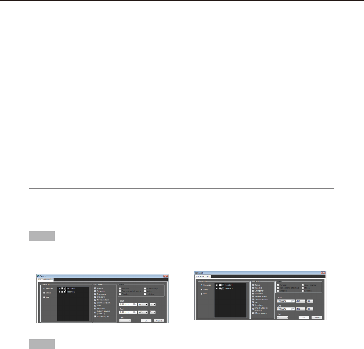
72
73
Search
Search recording event
Search for a recording event as follows.
It is possible to search for the following recording events by designating the search target; recorders, groups
and maps.
• Manual
• Terminal alarm
• SD memory rec.
• Schedule
• Command alarm
• EVENT LINKING (ASR500)
• Emergency
• VMD
• Site alarm
• Video loss
i-VMD
• Terminal
• Motion
• Removal and left behind
• Loitering
• Direction • Scene change
Note:
Only "SD memory" is unavailable to search together with other recording event types. To search for the SD •
memory data, search for the SD memory data alone.
Up to 1000 search results will be displayed. When more than 1000 search results are found, the latest 1000 •
search results will be displayed in the search result list. When searching in multiple recorders, number of
search results per a recorder will be (1000/number of recorders).
i-VMD search is available only when HD600 is selected for the search target.•
When searching via ASR500 to find images recorded at the recording frame rate of "1fps", it may take time •
when compared with search in the conventional recorders.
Determine the search conditions
Search for images by designating time & date, camera channel and recording event type (REC event search).
Step 1
Select "Search(S)..." under "Search(S)" on the menu
bar or click the [Search] icon on the tool bar.
The "Search" window will be displayed.
Step 2
Determine the search conditions.
<When recorders are to be searched>
Select "Recorder" for "Search by".1.
The registered recorders will be displayed in the →
tree view.
Select the recorders and the cameras to be 2.
searched.
Select the recording events to be searched.3.
Designate the time range to be searched by set-4.
ting the start time and the end time.
Determine to search for recorded images with text 5.
information or without it.
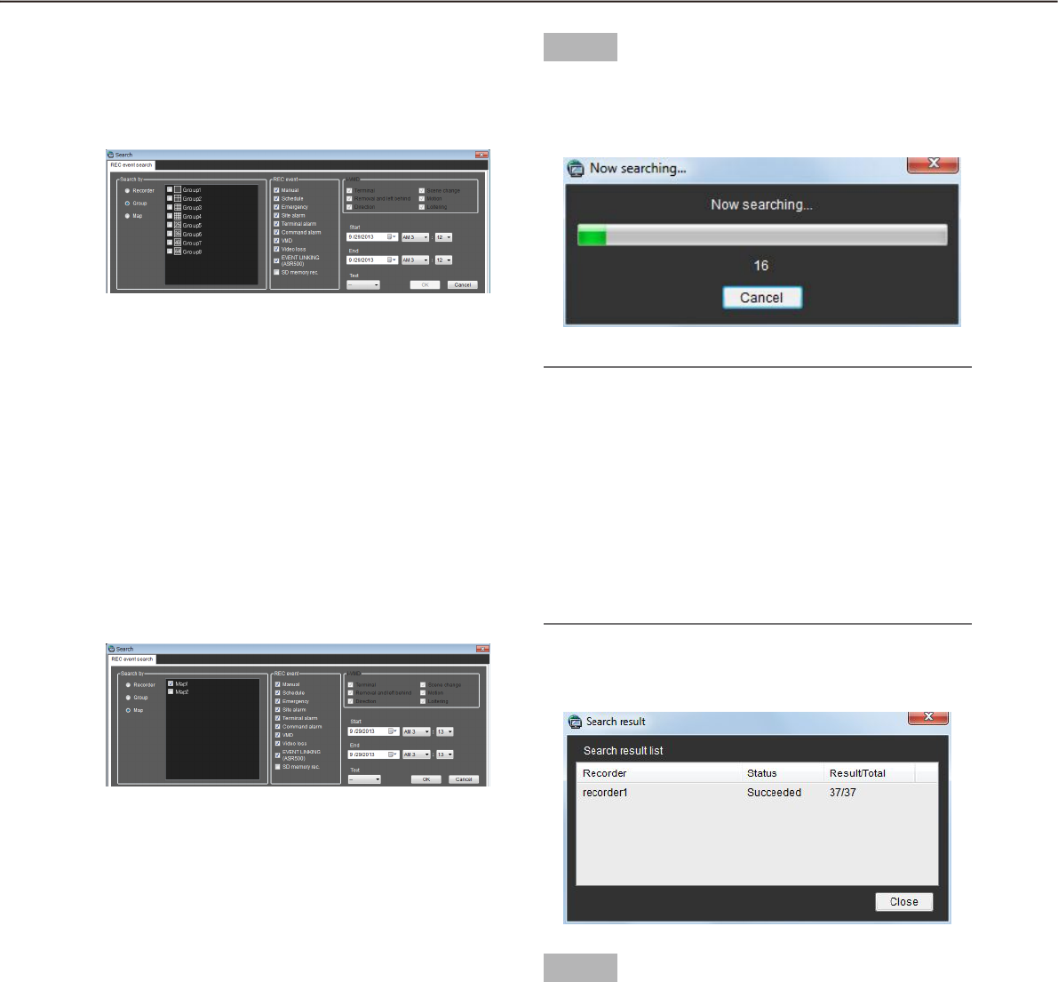
72
73
<When groups are to be searched>
Select "Group" for "Search by".1.
The registered groups will be displayed in list
form.
Select the groups to be searched.2.
Select the recording events to be searched.3.
Designate the time range to be searched by set-4.
ting the start time and the end time.
Determine to search for recorded images with text 5.
information or without it.
<When maps are to be searched>
Select "Map" for "Search by".1.
The registered maps will be displayed in list form.
Select the maps to be searched.2.
Select the recording events to be searched.3.
Designate the time range to be searched by set-4.
ting the start time and the end time.
Determine to search for recorded images with text 5.
information or without it.
Step 3
Click the [OK] button.
Search will start and the window with the
progress bar will be displayed.
Note:
When playback is being performed on the opera-•
tion window, playback will stop and live images
will be displayed.
Search result will keep on being added to the •
search result list while the window with the
progress bar is being displayed. When the
[Cancel] button is clicked while the window with
the progress bar is being displayed, search results
added to the search result list until the [Cancel]
button is clicked will not be deleted.
When the search is complete, the "Search result"
window will be displayed.
Step 4
Click the [Close] button.
The confirmation window will close.
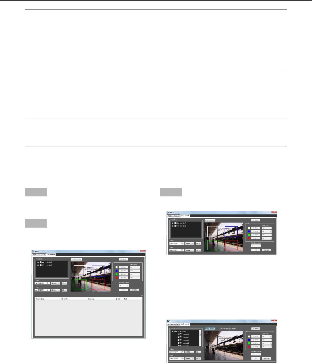
74
75
Note:
The search results will be displayed with the following information; time & date, recorder title, camera title, •
recording event type, with or without text.
When a result is clicked, the "Search" window will close and the selected image will be displayed on a •
1-screen. When playback of the selected result starts, the descriptions of the selected result will be dis-
played in the search panel of the operation window. Refer to the "Play recorded images using the "Search"
panel" section (+ page 77) for further information about the "Search" panel.
Once a playback is performed from the search results, the search result will not be deleted until a new •
search is performed or until the user logged out or exit the software.
Search for times and dates of motion-containing images
The times and dates of images containing a motion are searched for from recorded images.
Note:
This function is available only with ND400, HD600 or NV200.•
If ND400, HD600 or NV200 is registered, the VMD search tab will be displayed.•
Up to 200 search results can be displayed.•
Determine the search conditions
The time & date, camera channel, and motion detection area are specified to perform searching. (VMD search)
Step 1
Select "Search(S)..." under "Search(S)" on the menu
bar or click the [Search] icon on the tool bar.
Step 2
Click the [VMD search] tab on the search window.
The "VMD search" window will be displayed.
Step 3
Determine the search conditions.
Select a recorder and a camera to be searched for 1.
from the search target list. Only one recorder and
one camera are selectable.
Designate the time range to be searched by set-2.
ting the start time and the end time.
Click the [Image display] button.3.
The image of the camera to be searched for is
displayed.

74
75
Note:
The image on the operation window will be •
cleared.
Specify areas by dragging on the image area. 4.
Up to 4 areas can be specified.
Note:
When the recorder to be searched is the HD600 •
and the image of the camera is specified for the
detection area from the top to bottom, search will
be unavailable. (The area whose search will be
available is the same as that configured on the
HD600.)
Step 4
Click the [OK] button.
Search will start and the window with the
progress bar will be displayed. When the search
is complete, the "Search result" window will be
displayed.
Refer to "Play recorded images from the search result
list" (+ page 76) for playback from the search result
list.
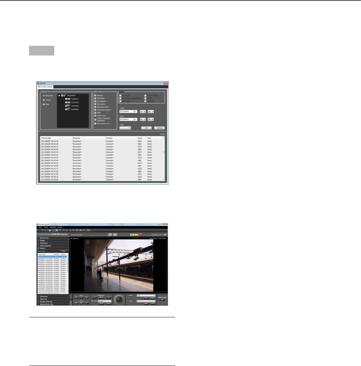
76
77
Play from the search results
Play recorded images from the search result list
It is possible to play images displayed in the search result list.
Step 1
Click the desired result displayed in the search result
list.
The "Search" window will close and the images of
the selected result will be displayed on a 1-screen
in the image display area.
Note:
Playback of the search result is also available by •
clicking a desired result displayed in the "Search"
panel. Refer to the "Play recorded images using
the "Search" panel" section (+ page 77) for fur-
ther information about the "Search" panel.
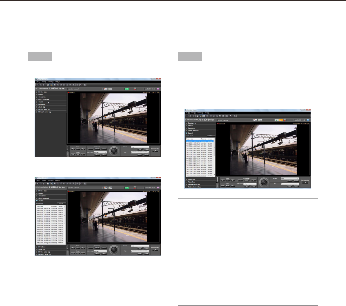
76
77
Play recorded images using the "Search" panel
The description of the search results displayed in the search result list will be displayed in the "Search" panel in
list form. Play recorded images of the desired result displayed in the "Search" panel as follows.
Step 1
Click the "Search" bar on the function panel.
The "Search" panel will be displayed.
The following are descriptions about each item dis-
played on the "Search" panel.
n [Search...] button
Click this button to display the "Search" window.
n Search result list
The search results will be displayed with the following
information; time & date, recorder title, camera title,
recording event type, with or without text.
Step 2
Click the desired result displayed in the search result
list.
Recorded images of the selected result will be
displayed on a 1-screen in the image display
area.
Note:
When clicking a result displayed in the search re-•
sult list, recorded images of the respective result
will be displayed on a 1-screen.
When playback is started, all images displayed in
the image display areas will be cleared.
When right-clicking on the search result list, the •
pop-up menu will be displayed.
Playback of recorded images of the specific group
is available by selecting the desired group from
the group list displayed on the sub menu of the
right-click pop-up menu.
(When "SD memory" has been selected for the
search, the group playback is unavailable.)
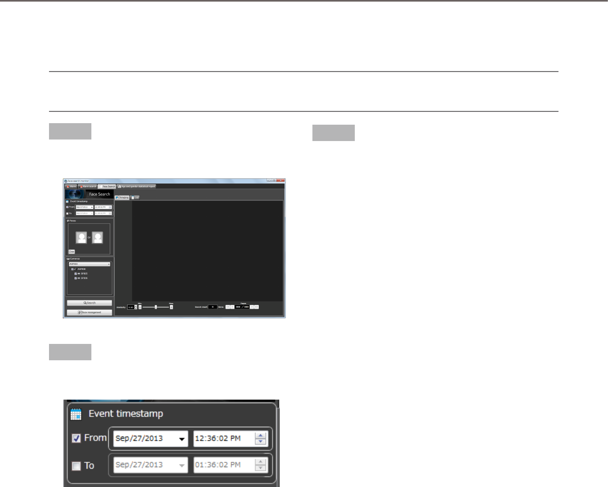
78
79
Search face
Search by time and date
Perform the face search by designating time and date.
Important:
To use the face search function, it is necessary to purchase WV-ASF900 and the extension software WV-•
ASE231.
Step 1
Click the [Face search] tab on the "Face Search" win-
dow.
Step 2
Select the start time and the end time of "Event
timesramp".
n From
Select the start time of period to be searched from
"2008/1/1" - "2034/12/31". Select a number for hour
from "0" - "23". Select a number for minute (1 minute
step).
n To
Select the end time of period to be searched from
"2008/1/1" - "2034/12/31". Select a number for hour
from "0" - "23". Select a number for minute (1 minute
step).
Step 3
Click the [Search] button.
The search result list will be displayed .
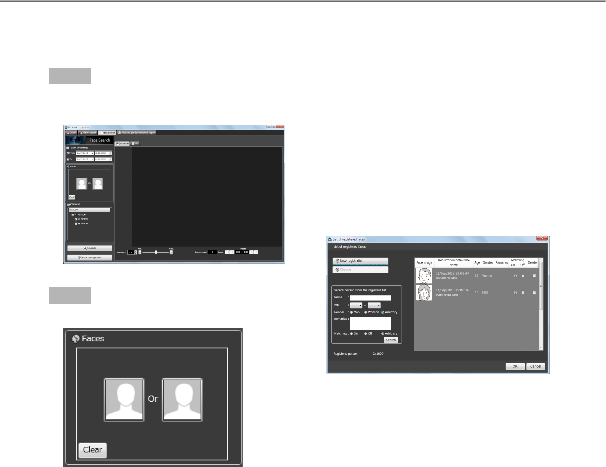
78
79
Search by face
Perform the face search by designating face features.
Step 1
Click the [Face search] tab on the "Face Search" win-
dow.
Step 2
Designate a face image.
n Person icon
The face image setting can be configured as follows.
Display the "List of registered faces" window by •
left-clicking the person icon, and then select a
face image.
Drag and drop the face image of the search result •
onto the person icon.
Right-click on the person icon, and then select •
from the following menu.
[Select face image from the registerd list]
[Select face image from the snapshot]
Right-click on a face image of paused playback •
image of ASM200 operation software, and select
[Select face image] from the menu. Right-click on
a face image in the displayed face image list, and
then select [Set this face to filter 1] or [Set this
face to filter 2] from the displayed menu.
(* This operation is available only when the "Face
Search" page is being displayed.)
n [Clear] button
Clear both images of filter 1 and 2.
Designate the person (face image) to be
searched
Select from the registered images•
Right-click on the person icon of "Faces" on the
"Face Search" page and select [Select face image
from the registered list] from the menu.
The "List of registered faces" window will be
displayed.
n Search result
To register a face image from the search result
thumbnail in filter 1, right-click on the face thumbnail
and select [Set this face to filter 1] from the menu.
To register in filter 2, right-click on the face thumbnail
and select [Set this face to filter 2] from the menu.
n [OK] button
Close the "List of registered faces" window and apply
the search condition.
n [Cancel] button
Close the "List of registered faces" window and can-
cel the search condition.
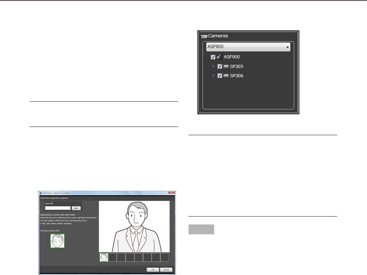
80
81
Select face image from the snapshot•
Right-click on the person icon of "Faces" on the
"Face Search" page and select [Select face image
from the snapshot] from the menu.
The "Select face image from the snapshot"
window will be displayed.
n [Ref.] button
Select an image file to be read on the "Select face
image from the snapshot" window.
Note:
The available file formats are JPEG, PNG and •
BMP.
n Snapshot display area
When an image file is read out, the face detection
process will be carried out and white border frame
will be displayed around each face.
The detected faces will be displayed below the
image.
n Image display area for setting the search
condition
The selected face image will be displayed.
n [OK] button
Close the registration window and apply the search
condition.
n [Cancel] button
Close the registration window and cancel the search
condition.
Designate the camera to be searched
Check the checkbox of the camera to be searched.
Note:
The cameras obtained by "Face search server •
registration" of the setup software will be dis-
played in the tree.
When the checkbox of parent node (server) is •
checked, the checkboxes of all the child nodes
will be checked automatically.
When the checkbox of "Parent node (server)" is •
unchecked, the checkboxes of all the child nodes
will be unchecked automatically.
Step 3
Click the [Search] button.
The search result list will be displayed .
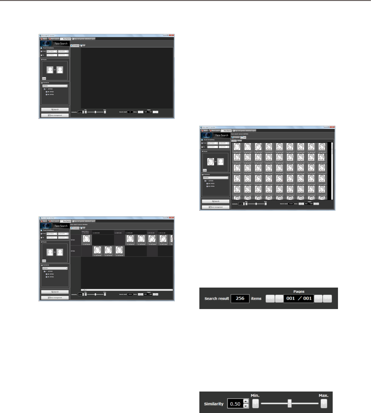
80
81
<When displaying in "List">
Click the [List] tab.
The search result will be displayed with thumbnail
images in list form.
When "Face image" is set for the search condition,
the search result will be listed in order of the highest
score of similarity.
When "Face image" is not set for the search condi-
tion, the search result will be listed in order of the
detection time.
n Number of the search result, page
information
Total number of search result and the page number
of the currently displayed page will be displayed as
shown below.
The buttons to turn pages will be displayed as shown
below.
n Filtering display of search result
It is possible to display search result after filtering the
result using the similarity filtering slider located below
the search result display area.
By moving the slider to the left or right, it is possible
to specify the lowest similarity score and only images
with the similarity score higher than the value speci-
fied by the slider.
Play recorded image in search result
Click the [Search] button.
The search result list will be displayed .
There are two types of displaying the search result;
"Timeline" and "List".
<When displaying in "Timeline">
Click the [Timeline] tab.
The search result will be displayed with mapped
thumbnail images on the plane with two axes of
Time" and "Place".

82
83
Note:
When filtered by the similarity score, filtering of •
the search result of both the timeline display and
the list display will start and display the result
again. (Not starting search again)
n Attribute information
In the search result, the face image and the additional
information of "Similarity" and "Time" (when image is
captured) will be displayed.
Operation from thumbnail image of search
result
The following are available by operation using thumb-
nail image of search result
Apply to filter of the face search•
Right-click on a thumbnail image and select "Set
this face to filter 1" from the right-click menu.
The selected image will be displayed in the →
section of "Person" of the search display win-
dow.
Register as person (face) of whom alarm is to be •
notified
Right-click on the thumbnail image and select
"Register this face" from the right-click menu.
The "Select and register face image from →
snapshot” window will be displayed. ("Register
this face" (☞ page 89))
Playback of recorded images•
Right-click on the thumbnail image and select
"Play the video" from the right-click menu.
Image recorded at the alarm occurrence time →
will be played.
Recorded images will be played on the operation
window of the operation software.
Note:
When the operation window is used with a multi-•
screen, it will be switched to 1-screen.
It is also possible to play recorded images by •
double-clicking a thumbnail image.
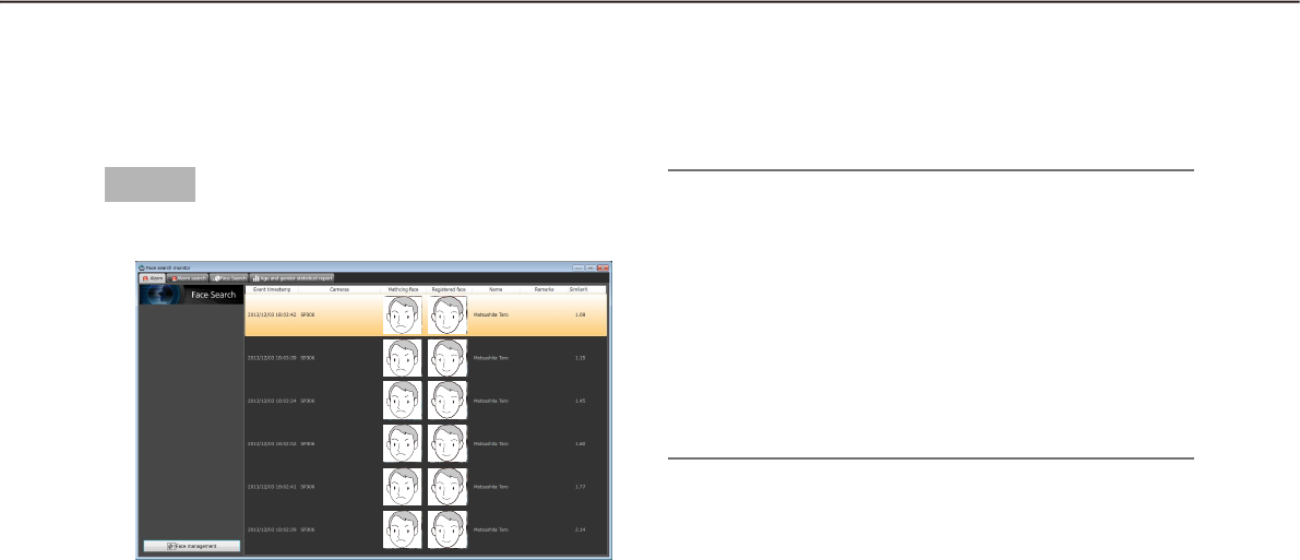
82
83
Step 1
Click the [Alarm] tab on the "Face Search" window.
The details are as follows.
■ Event timestamp
Time and date when the face search alarm is
occurred
■ Cameras
Name of the camera that notified of the face search
alarm
■ Matching face
Indicates the thumbnail image verified by the face
search server
■ Registered face
Indicates the matched face image by the face search
in the registered face thumbnail images
■ Name
Indicates the face of the appeared person
■ Remarks
Additional information relating to the registered per-
son (face), etc.
■ Similarity
Score of facial similarity between the registered face
image and the detected face image
Check the alarm notification
Display the "Alarm notification" window
When received a face search alarm notification, contents of the alarm will be displayed in list form.
Note:
When displaying a window (such as the search •
window or the generate report window) other than
the "Alarm" page on the face search window, the
displayed window will not automatically be
switched to the "Alarm" page even if received an
alarm notification.
The "Alarm" page will automatically be displayed •
by receiving a face search alarm when the face
search window is not displayed.
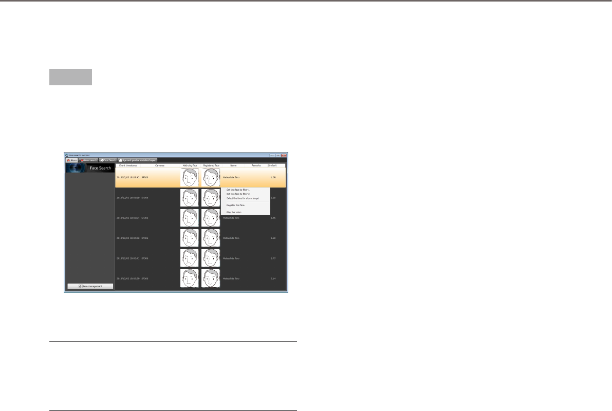
84
85
Step 1
Right-click on a line of the person whose video
appearance is to be checked in the notification list on
the "Alarm" page, and then select [Play the video]
from the right-click menu.
Recorded images will be played on the operation →
window.
Note:
When the operation window is used with a multi-•
screen, it will be switched to 1-screen.
It is also possible to play recorded images by •
double-clicking a list item.
Play images recorded by the alarm recording
Play images recorded at the alarm occurrence time from the recorder.
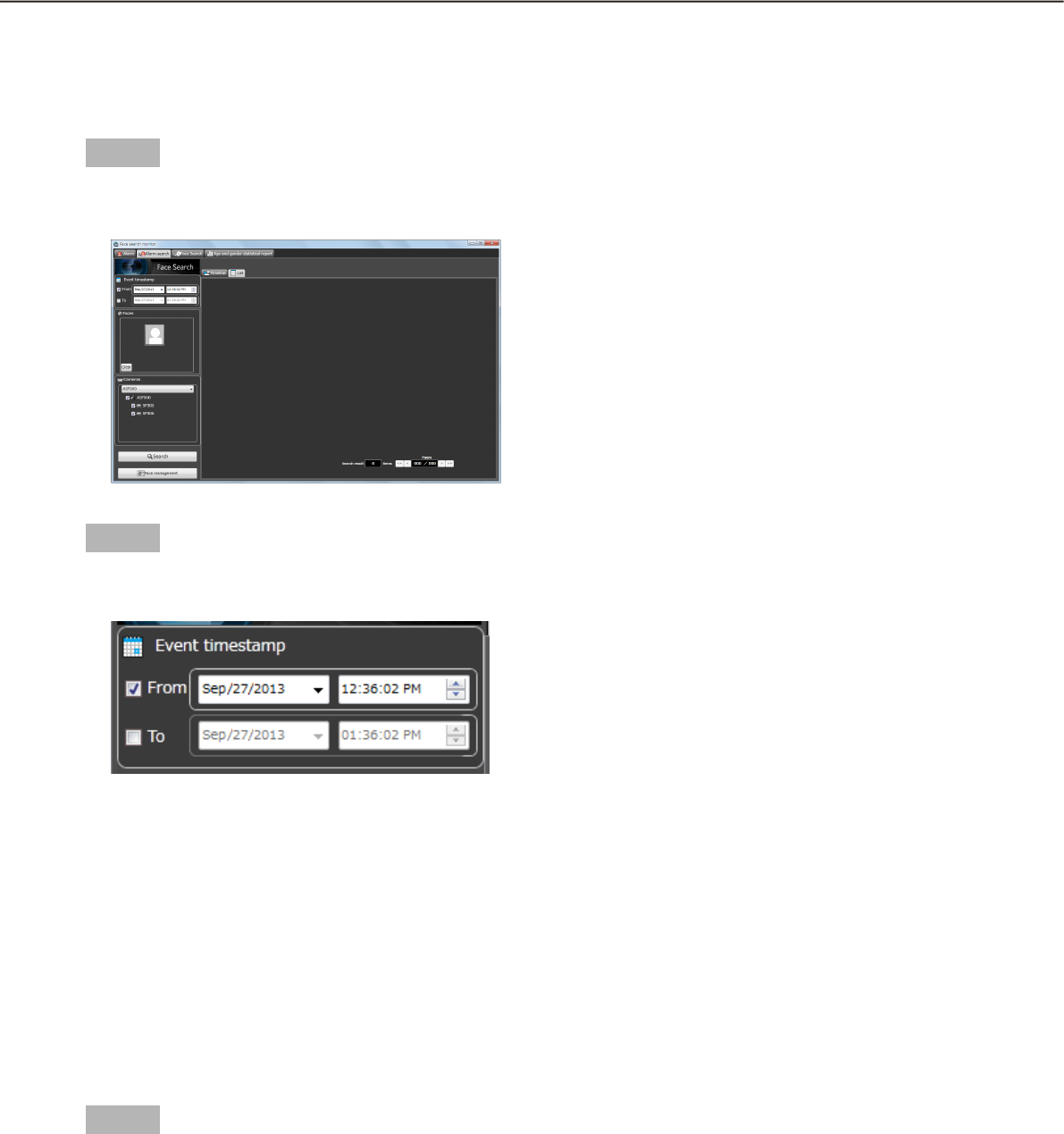
84
85
Search the alarm notification
Search by time and date
Perform the alarm notification search by designating time and date.
Step 1
Click the [Alarm search] tab on the "Face Search"
window.
Step 2
Select the start time and the end time of "Event
timesramp".
■ From
Select the start time of period to be searched from
"2008/1/1" - "2034/12/31". Select a number for hour
from "0" - "23". Select a number for minute (1 minute
step).
■ To
Select the end time of period to be searched from
"2008/1/1" - "2034/12/31". Select a number for hour
from "0" - "23". Select a number for minute (1 minute
step).
Step 3
Click the [Search] button.
The "Search result" window will be displayed.
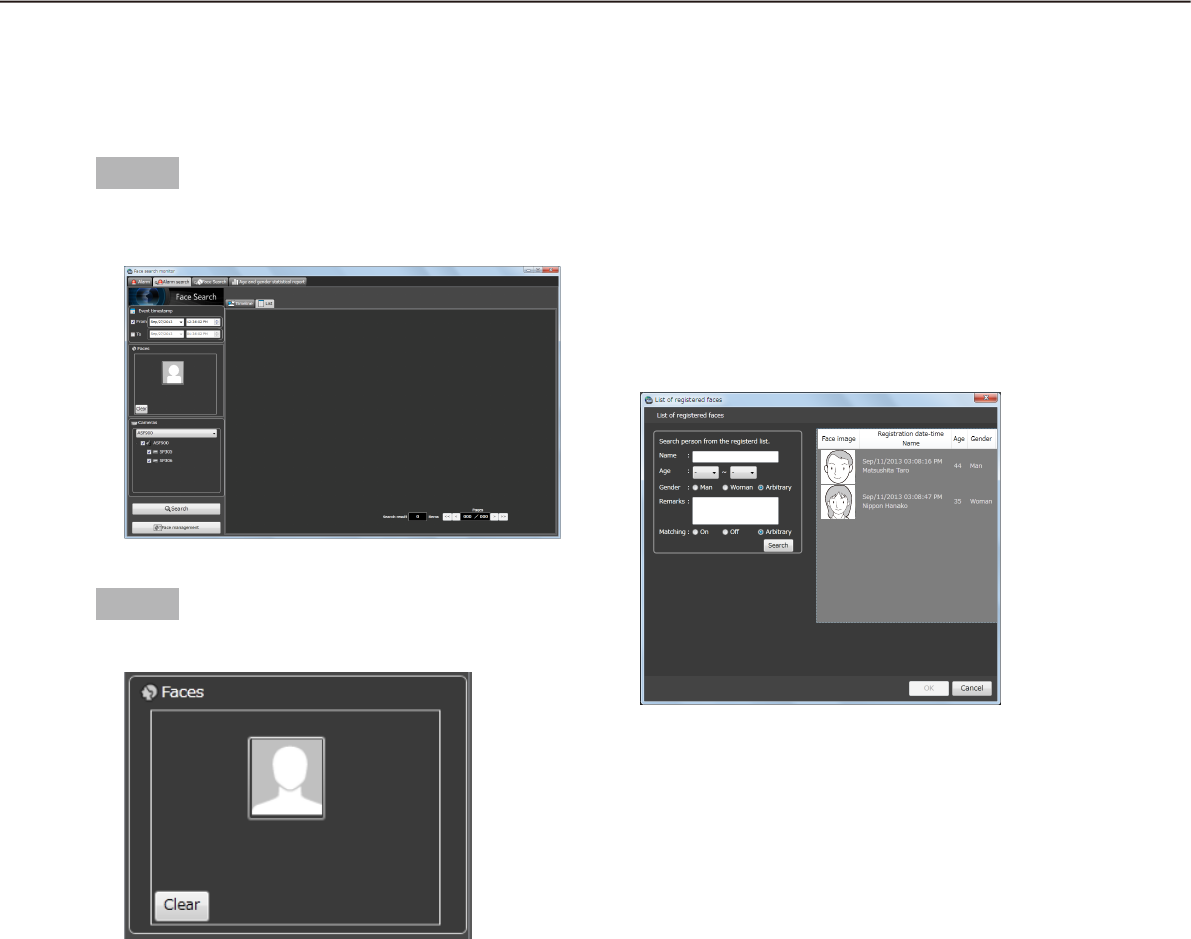
86
87
Search by person (face)
Perform the face search by designating face features.
Step 1
Click the [Alarm search] tab on the "Face Search"
window.
Step 2
Designate a face image.
■ Person icon
The face image setting can be configured as follows.
Display the "List of registered faces" window by •
left-clicking the person icon, and then select a
face image.
Right-click on the person icon, and then select •
from the following menu.
[Select face image from the registered list]
Drag and drop the face image of the search result •
onto the person icon.
■ [Clear] button
Clear the search condition.
Designate the person (face image) to be
searched
Select from the registered images•
Right-click the person icon of "Faces" on the
"Alarm search" page and select [Select face
image from the registered list] from the menu.
The "List of registered faces" window will be
displayed.
■ List item
Select a person to be searched from the "List of reg-
istered faces" displayed on the right side.
■ [OK] button
Close the "List of registered faces" window and apply
the search condition.
■ [Cancel] button
Close the "List of registered faces" window and can-
cel the search condition.
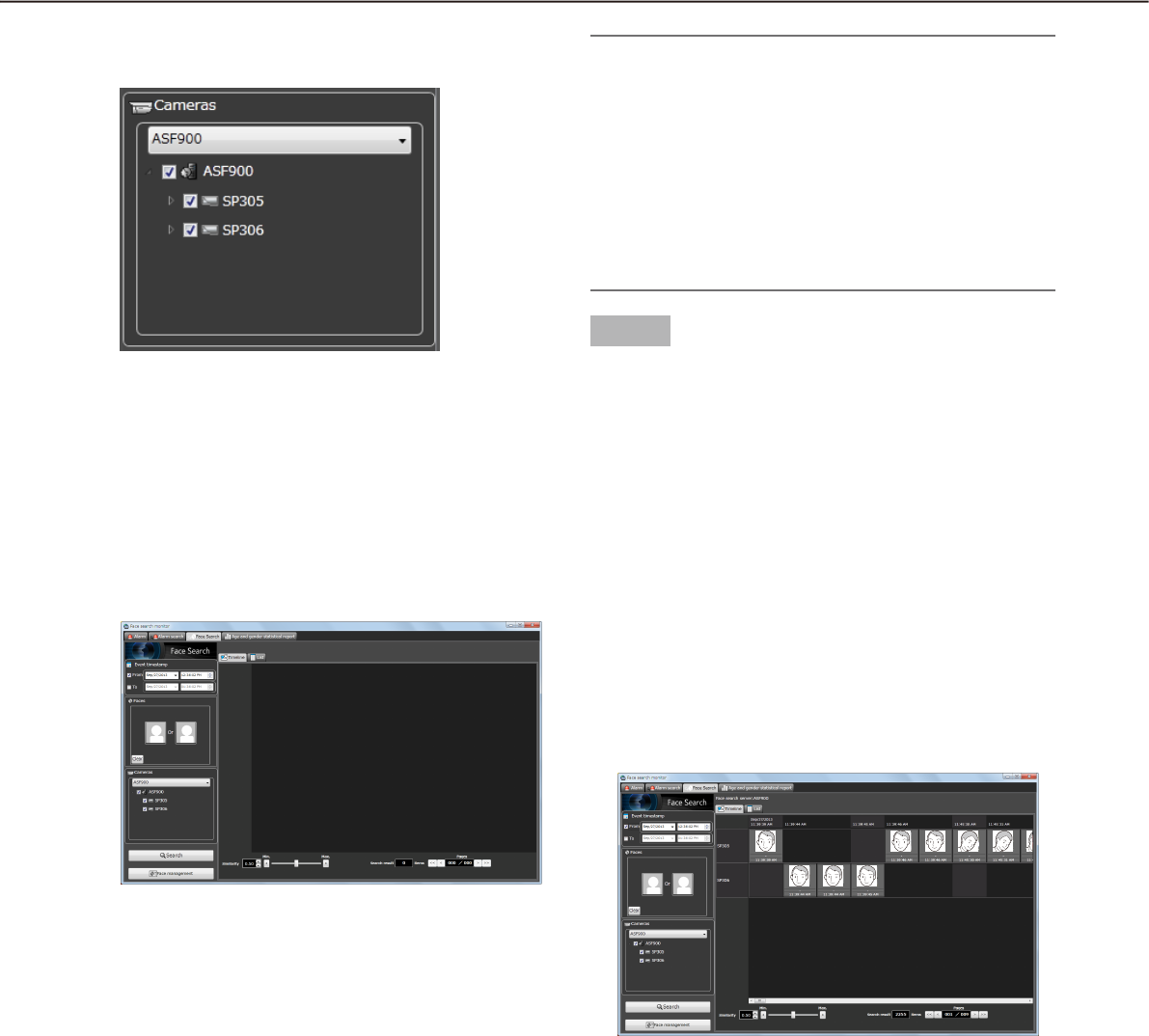
86
87
Designate the camera to be searched
Check the checkbox of the camera to be searched.
Note:
The cameras obtained by "Face search server •
registration" of the setup software will be dis-
played in the tree.
When the checkbox of parent node (server) is •
checked, the checkboxes of all the child nodes
will be checked automatically.
When the checkbox of "Parent node (server)" is •
unchecked, the checkboxes of all the child nodes
will be unchecked automatically.
Step 3
Click the [Search] button.
The "Search result" window will be displayed.
Play recorded image in search result
Click the [Search] button.
The "Search result" window will be displayed.
There are two types of displaying the search result;
"Timeline" and "List".
<When displaying in "Timeline">
Click the [Timeline] tab.
The search result will be displayed with mapped
thumbnail images on the plane with two axes of
"Time" and "Place".
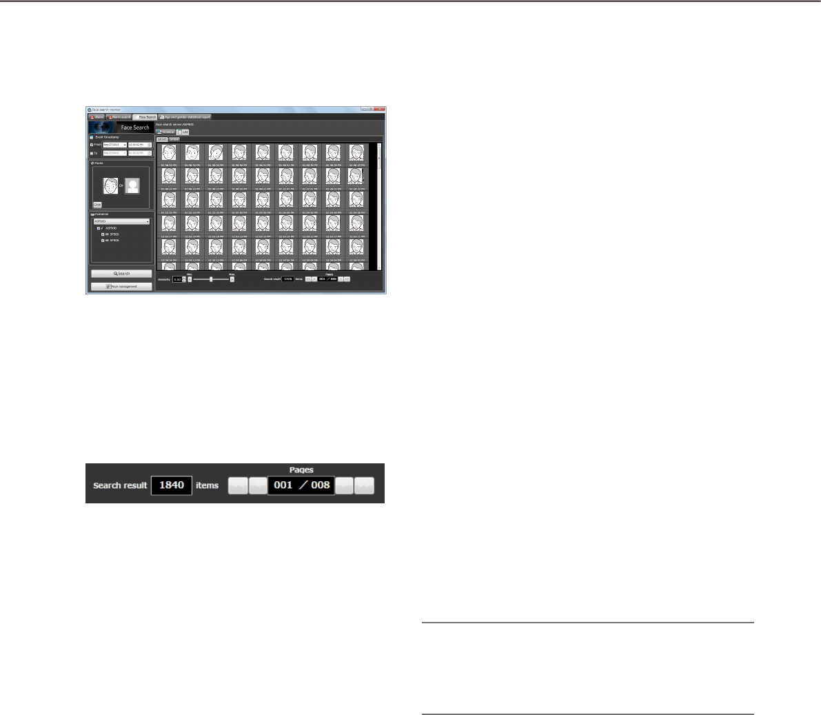
88
89
<When displaying in "List">
Click the [List] tab.
Search result will be displayed in list form.
■ Number of the search result, page
information
Total number of search result and the page number
of the currently displayed page will be displayed as
shown below.
The buttons to turn pages will be displayed as shown
below.
Operation from thumbnail image of search
result
The following are available by operation using thumb-
nail image of search result
Apply to filter of the face search•
Right-click on a thumbnail image and select "Set
this face to filter 1" or "Set this face to filter 2"
from the right-click menu.
The selected image will be displayed in the
section of [Person] of the search display win-
dow.
Register as person (face) of whom alarm is to be •
notified
Right-click on the thumbnail image and select
"Register this face" from the right-click menu.
The " Select and register face image from
snapshot" window will be displayed. ("Register
this face" (☞ page 89))
Apply to filter of the alarm search•
Right-click on the thumbnail image and select
"Set this face to alarm search filter" from the right-
click menu.
The selected image will be displayed in the
section of [Person] of the alarm search display
window.
Playback of recorded images•
Right-click on the thumbnail image and select
"Play the video" from the right-click menu.
Image recorded at the alarm occurrence time
will be played.
Recorded images will be played on the opera-
tion window of the operation software.
Note:
When the operation window is used with a multi-•
screen, it will be switched to 1-screen.
It is also possible to play recorded images by •
double-clicking a thumbnail image.
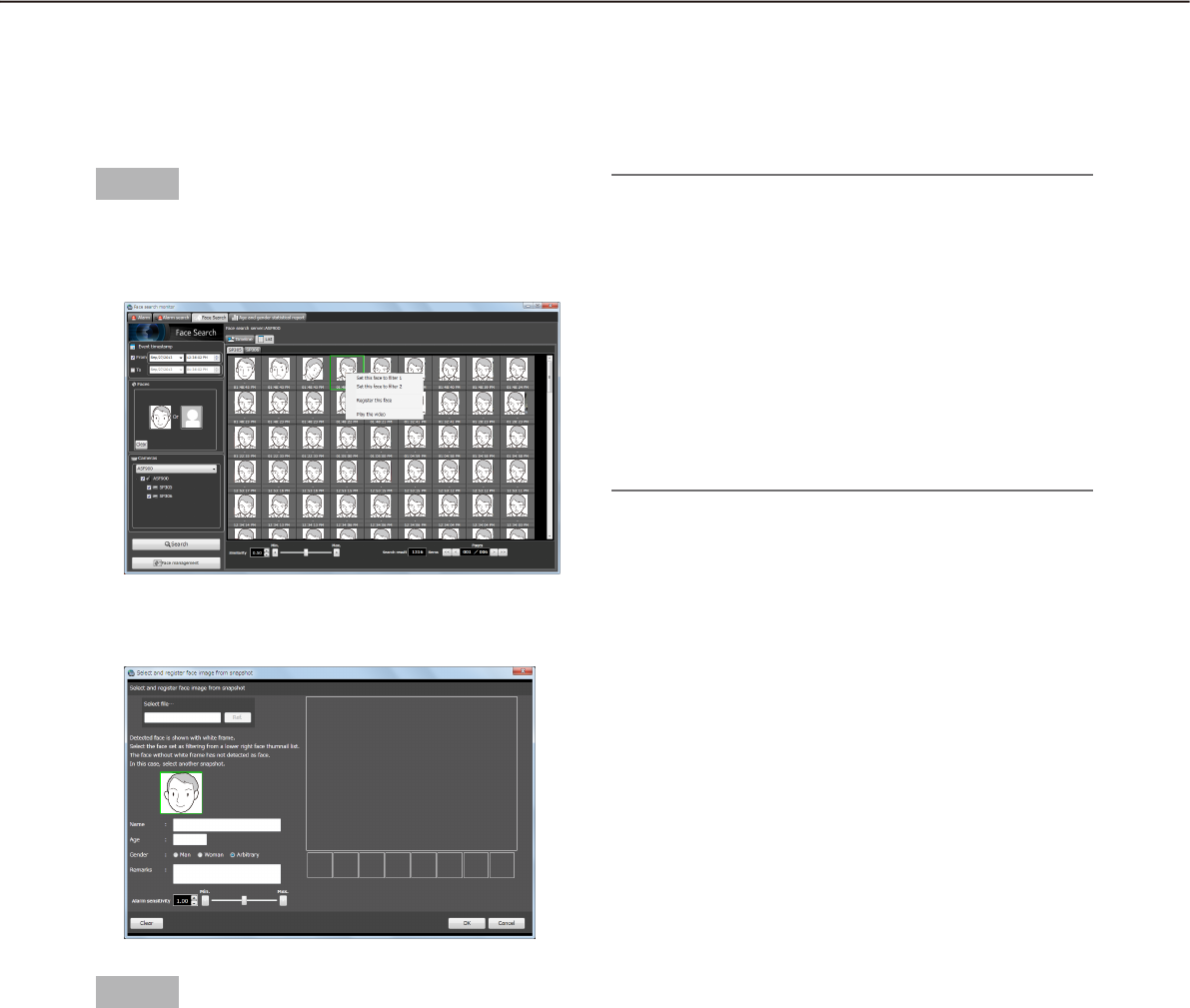
88
89
Register a face for the alarm notification
Register from a face thumbnail image
It is possible to register from the search result of "Search face" or "Search person (face)" of "Search the alarm
notification".
Step 1
On the "Search result" window of "Search person
(face)", right-click on a face thumbnail image and
select "Register this face" from the right-click menu.
The "Select and register face image from snap-
shot" window will be displayed.
Step 2
After entering the following information, click the [OK]
button.
■ Name
■ Age
■ Gen der
Note:
The alarm sensitivity is the sensitivity to be used •
to match with the registered faces. This setting
can be applied to each person. Normally, use with
the default setting.
The lower the alarm sensitivity level is, the higher •
the rate of matching with the registered faces will
become. However, the matching accuracy may
drop. The higher the alarm sensitivity level is, the
lower the rate of false matching with the regis-
tered faces will become. However, the matching
rate with the registered faces may drop.
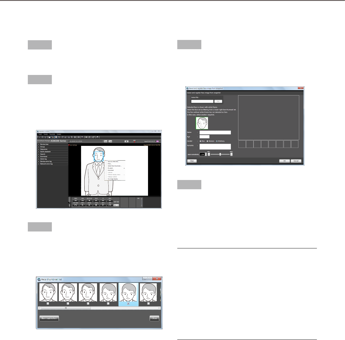
90
91
Register from recorded images
It is possible to register from playback images on the recorder.
Step 1
Play recorded images while displaying the operation
window with 1-screen.
Step 2
Pause the playback when the person to be registered
appeared.
When detection of the face image succeeded,
square frames will be displayed around all the de-
tected faces.
Step 3
Right-click on the face image to be registered and
select "Face select" from the right-click menu.
The face search from recorded images will start
and the result will be displayed with the detected
faces in list form.
The detected face images will be checked and
verified, and the checkbox of the face image with
the highest score will automatically be checked.
Step 4
Check the checkbox of the face image to be regis-
tered, and then click the [New registration] button.
The " Select and register face image from snap-
shot" window will be displayed.
Step 5
After entering the following information, click the [OK]
button.
■ Name
■ Age
■ Gender
Note:
The alarm sensitivity is the sensitivity to be used •
to match with the registered faces. This setting
can be applied to each person. Normally, use with
the default setting.
The lower the alarm sensitivity level is, the higher •
the rate of matching with the registered faces will
become. However, the matching accuracy may
drop. The higher the alarm sensitivity level is, the
lower the rate of false matching with the regis-
tered faces will become. However, the matching
rate with the registered faces may drop.
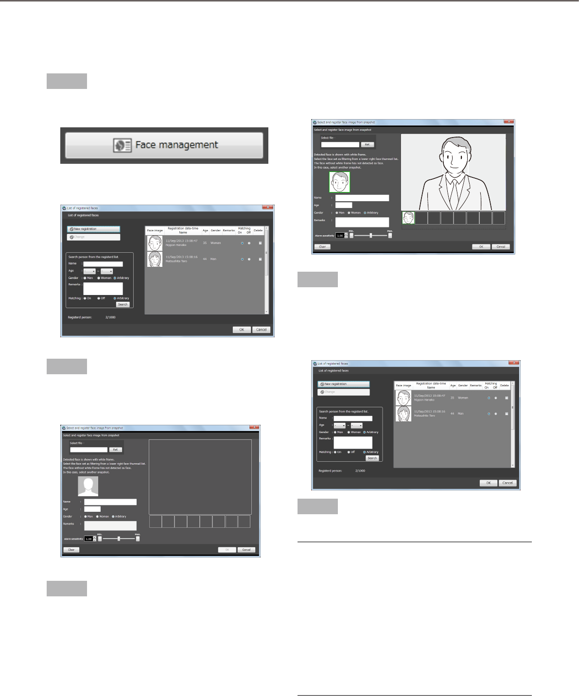
90
91
Register from snapshot
It is possible to register from a still image (snapshot) whose format is JPEG, PNG or BMP.
Step 1
Click the [Face management] button on the "Face
Search" window.
The "List of registered faces" window will be dis-
played.
Step 2
Click the [New registration] button.
The "Select and register face image from snap-
shot" window will be displayed.
Step 3
Click the [Browse...] button.
Select an image file to be read on the file selection
window.
The face detection from the image will start and
square frames will be displayed around all the
faces when face images are detected.
Step 4
Click a face image to be registered from the list, and
click the [OK] button after entering information such
as name, age and gender.
The registered person (face) will be displayed in
the list on the "List of registered faces" window.
Step 5
Click the [OK] button.
Note:
The alarm sensitivity is the sensitivity to be used •
to match with the registered faces. This setting
can be applied to each person. Normally, use with
the default setting.
The lower the alarm sensitivity level is, the higher •
the rate of matching with the registered faces will
become. However, the matching accuracy may
drop. The higher the alarm sensitivity level is, the
lower the rate of false matching with the regis-
tered faces will become. However, the matching
rate with the registered faces may drop.
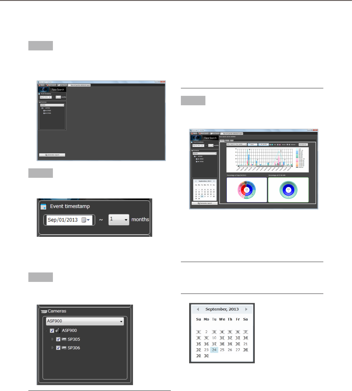
92
93
Display the statistical graphics of age/gender/head-count
Display the statistical results
It is possible to display the statistic results of age, gender and head count for each camera.
Step 1
Click the [Age and Gender] tab on the "Face search
monitor" window.
The "Age and Gender" page will be displayed.
Step 2
Select the start date and the period to display the
statistical results in the "Display period" section.
Select the start date of period from "2008/1/1" -
"2034/12/31". Select a number for month from "1" -
"12".
Step 3
Select the face search server and the cameras to dis-
play statistics in the "Camera" section.
Note:
The cameras obtained by "Face search server •
registration" of the setup software will be dis-
played in the tree.
When the checkbox of parent node (server) is •
checked, the checkboxes of all the child nodes
will be checked automatically.
When the checkbox of "Parent node (server)" is •
unchecked, the checkboxes of all the child nodes
will be unchecked automatically.
Step 4
Click the [Generate report] button.
The statistical results will be displayed .
The following display options can be set.
■ Calendar
Select the date to display statistics in the [Calender]
section.
Note:
Only the date with data will be displayed.•
Date without data will be displayed with the "×" •
mark.
■ Graph type
Select the graph type to be displayed from the follow-
ing.
Daily trend (15 minute scale)/Daily trend (30 minute
scale)/Daily trend (1 hour scale)/Weekly trend/Days
trend/Monthly trend

92
93
■ [Stack]/[Ratio] buttons
Switches the graph display based on the accumu-
lated data or the proportional data.
Note:
The line graph is available only when displaying •
based on the accumulated data (stack) and the
data point labels will be displayed together.
■ [By gender]/[By total] buttons
Switches the graph display based on the gender or
the total number.
Step 1
Click the [Download CSV file] button on the "Generate
report" window.
The folder selection window will be displayed.
Step 2
Select the destination folder of the CSV file to be
downloaded and click the [OK] button.
The statistics data will be saved as the CSV file
whose character code is UTF-8 and comma sepa-
rated.
The name of the downloaded CSV file will be as fol-
low.
"ccccccc_yymmdd000000_yymmdd000000_00_00.
csv"
ccccccc: Name of the camera or "total"
yymmdd000000 (1st part): Start date of the period
(Year in last 2 digits)
yymmdd000000 (2nd part): End date of the period
(Year in last 2 digits)
CSV file format
Output example
#GUID,Aggregated Date,Gender Code,Age
Code,Period of time,The number of people
00200001-0000-0000-0000-
192168001100,2013/07/24,1,3,0900,0
00200001-0000-0000-0000-
192168001100,2013/07/24,1,3,0915,0
00200001-0000-0000-0000-
192168001100,2013/07/24,1,3,0930,0
00200001-0000-0000-0000-
192168001100,2013/07/24,1,3,0945,0
00200001-0000-0000-0000-
192168001100,2013/07/24,1,3,1000,0
...
The data item name and the each 15 minutes sum-
mary information will be output on the first line and
the second line respectively.
[GUID]
Camera GUID
[Aggregated Date]
Date
[Gender Code]
Gender code
-1: Unknown / 0: Male / 1: Female
[Age Code]
Age code
-1: Unknown / 1: 10s or younger / 2: 20s / 3: 30s /
4: 40s / 5: 50s 6: 60s or older
[Period of time]
Time 15 minutes each
[The number of people]
Head count
■ [Male]/[Female]/[Unknown] checkbox
Check the checkbox to display the desired informa-
tion in the graph display.
■ Circle graph
Select the items to be displayed with the data labels
of the circle graph.
Each time clicked on the circle graph, the label dis-
play will be switched to [Head count] [Ration]
[Title] [Head count].
Download the statistics results as a CSV file
It is possible to download the data used for the statistics display as a CSV file.

94
95
Change the display setting (Hide the display)
Display the border frame for face (Hide the border frame)
It is possible to display/hide the border frame displayed around a face when detected.
Important:
This function will be valid only when a camera having the face search function is connected to ASM200 and •
the face search function is ON.
<To display>
Confirm that the checkbox on the left of "Frame display with face (K)" under "Display (V)" on the menu bar of
the operation window or the live window is unchecked. Then, select "Frame display with face (K)" under
"Display (V)".
Square border frame will be displayed around the detected face and the checkbox on the left of "Frame dis-
play with face (K)" under "Display (V)" will be checked.
<To hide>
Confirm that the checkbox on the left of "Frame display with face (K)" under "Display (V)" on the menu bar of
the operation window or the live window is checked. Then, select "Frame display with face (K)" under "Display
(V)".
The square border frame around the detected face will be hidden and the checkbox on the left of "Frame
display with face (K)" under "Display (V)" will be unchecked.
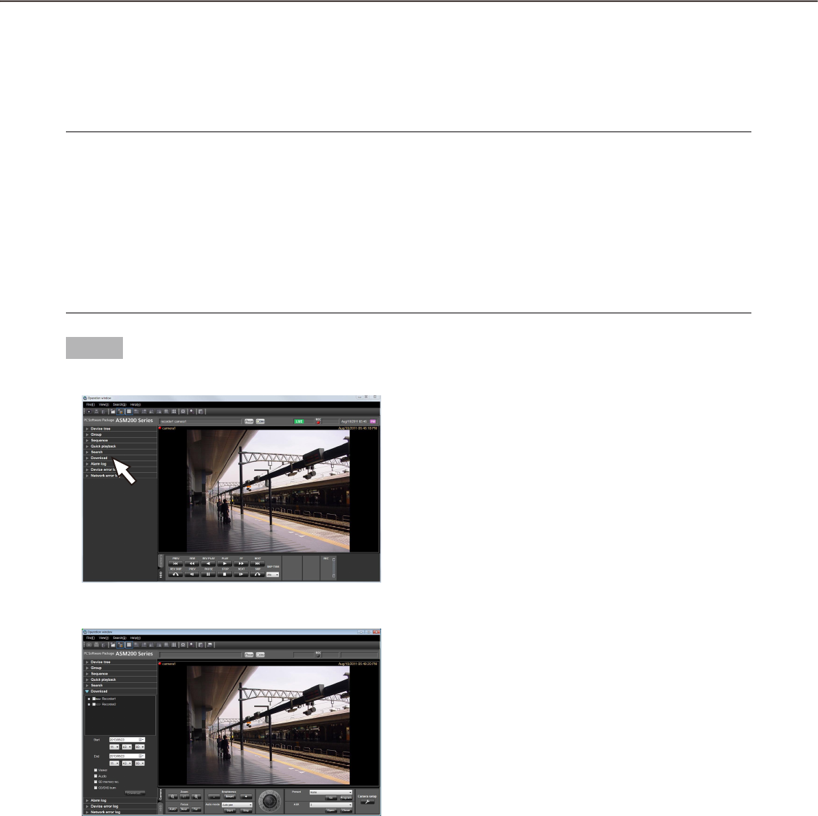
94
95
Save recorded images
Step 1
Click the "Download" bar on the function panel.
The "Download" panel will be displayed.
The following are descriptions about each item dis-
played on the "Download" panel.
n Recorders in the tree view
The recorders and the cameras as the target sources
of download will be displayed. Select the desired
recorders and the cameras.
n Start
Select the start time of time range for download.
Select the start time from "Jan/01/2005" -
"Dec/31/2034". Select a number for hour from
"AM12" - "PM11". Select a number for minute from
"00" - "59". Select a number for second from "00" -
"59".
n End
Select the end time of time range for download.
Select the end time from "Jan/01/2005" -
"Dec/31/2034". Select a number for hour from
"AM12" - "PM11". Select a number for minute from
"00" - "59". Select a number for second from "00" -
"59".
n Viewer
The viewer software will be downloaded together with
recorded images.
n Audio
Audio will be downloaded together with images.
n SD memory rec.
Recorded images transferred from the SD memory
card in the camera to the recorder will be down-
loaded.
n [Download...] button
The folder selection window will be displayed.
n CD/DVD burn
After download is completed, the recorded images
will be written on a CD/DVD recording media.
The supported media formats are CD-R/RW, DVD-R/
RW and DVD+R/RW.
Download recorded images
It is possible to download recorded image from the recorder onto the PC. FTP function is used to download
recorded images.
Download recorded images using the "Download" panel.
Note:
Recorded images of up to 64 cameras can be downloaded simultaneously. When multiple camera channels •
are selected, download of recorded images will be performed by the camera channels in order.
It is possible to select two or more recorders for the target sources of download, but it is impossible to •
download their images simultaneously.
When the same camera channel is selected two or more times, the address and underscore (_) will be
added to the head of each file name.
The maximum recording duration available for download is 24 hours.•
Images recorded in the designated time range will be divided into files of 10 minutes length each and down-•
loaded. The maximum time length of a downloaded file is 10 minutes.
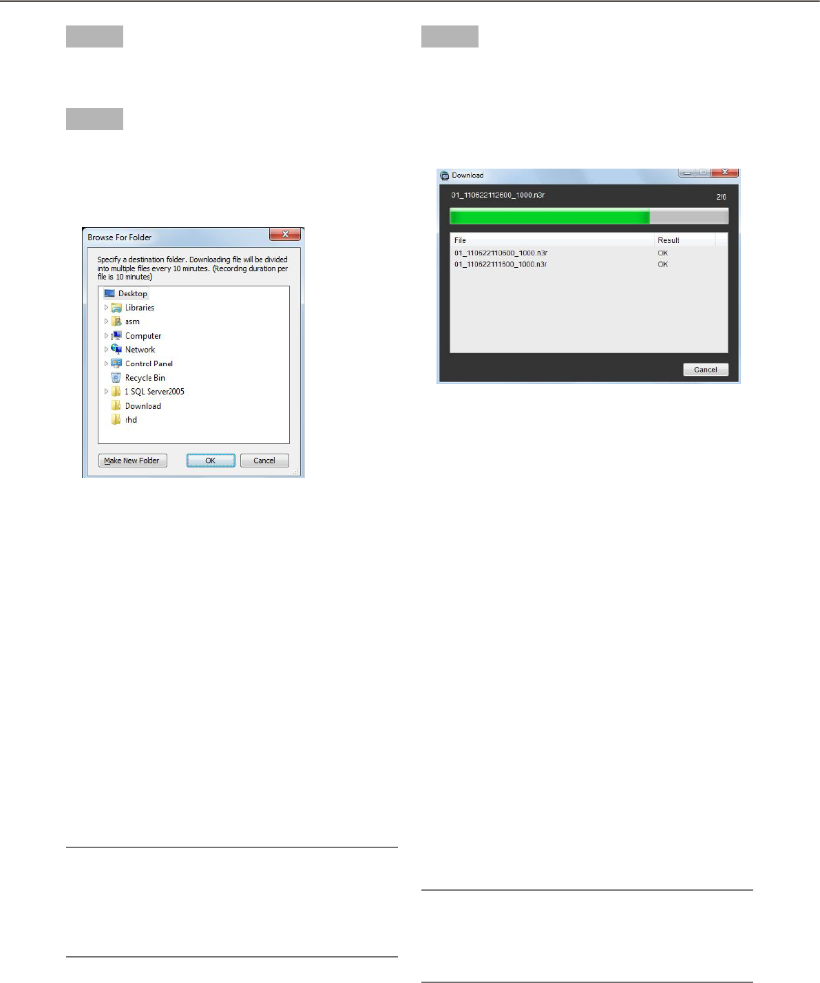
96
97
Step 2
Select the recorders and the cameras as the target
sources of download.
Step 3
Designate time range for download, and then click
the [Download...] button.
The window to specify a folder as the destination
of the downloaded files will be displayed.
The following are descriptions about each item dis-
played on the "Browse For Folder" window.
n Destination folder
Specify a folder as the destination of downloaded
files.
n [Make New Folder] button
Click this button to create a new folder in the selected
folder.
n [OK] button
The window will close and the download will start.
n [Cancel] button
The window will close and the download will be can-
celed.
Note:
The overwrite warning window will be displayed •
when a file of the same name already exists in the
folder. Click the [Cancel] button when wishing not
to overwrite the file. In this case, specify another
folder.
Step 4
Click the [OK] button after specifying a folder.
Download will start and the "Download" window
will be displayed. To cancel download, click the
[Cancel] button or the [×] button at the top right of
the window. Downloaded files will be stored in the
specified folder.
The following are descriptions about each item dis-
played on the "Download" window.
n Name of the file currently being downloaded
Name of the file currently being downloaded will be
displayed.
n Number of files
"Number of files downloaded"/"Number of files to be
downloaded".
n Progress bar
The status of the download will be displayed.
n List of files
Information of the downloaded files will be displayed
in list form.
File: Downloaded files will be displayed.
Result: The status of the download file will be dis-
played.
OK: Download of the file is successfully completed.
NG: Download of the file failed.
No data: No data was found in the selected recorder.
Failed to burn : The files could not be written on the
CD/DVD media since the available space is not
enough.
Note:
If the download failed, the result will be filed as a •
system log. Refer to WV-ASM200 Setup
Instructions (PDF) for further information about
logs.
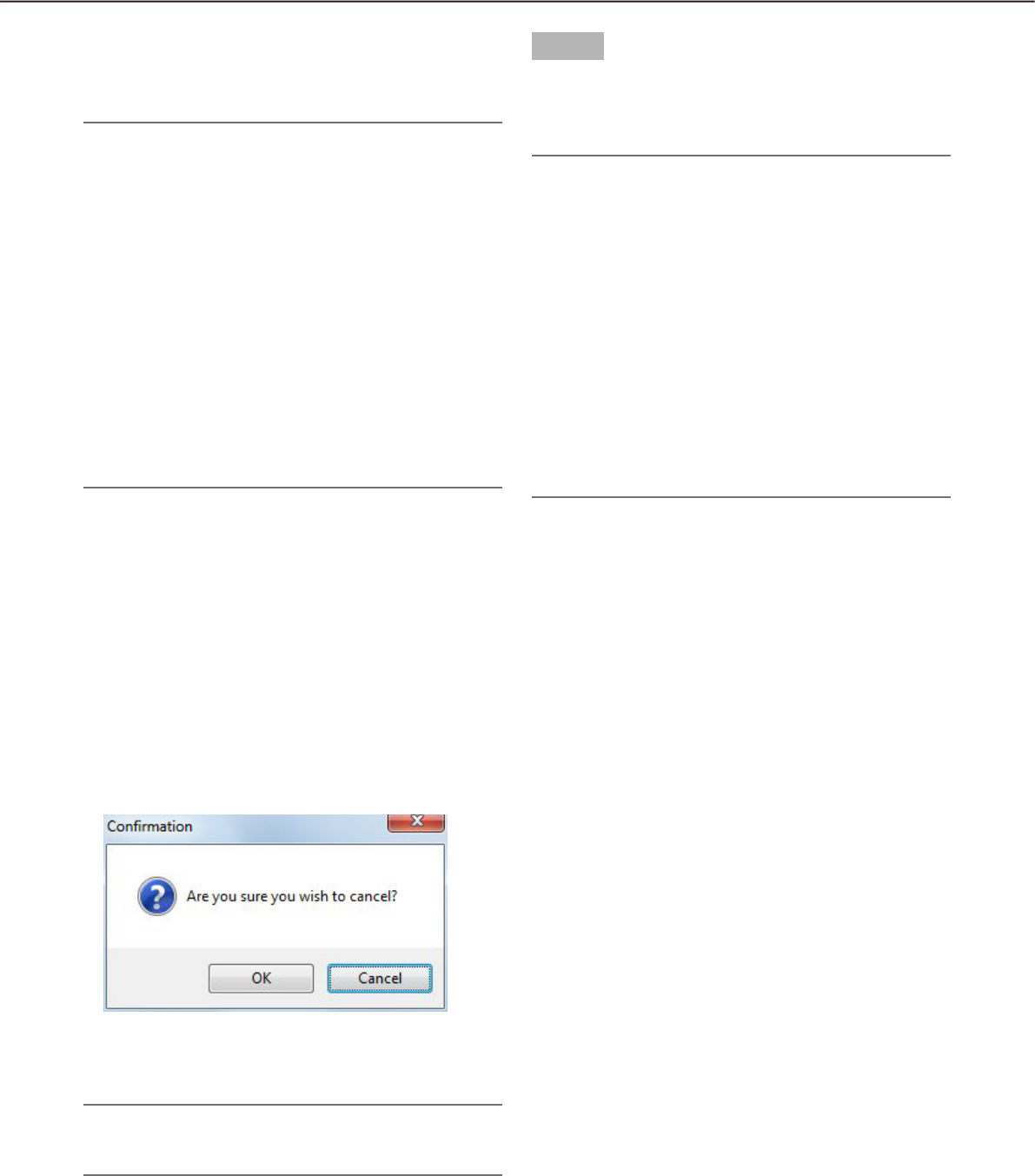
96
97
When the "CD/DVD burn" checkbox is checked, writ-
ing on the CD/DVD media will automatically start after
downloading all the files.
Note:
It is necessary to insert a writable media into the •
CD/DVD drive before starting download.
When the total size of the downloaded files is •
greater than the available space of the CD/DVD
media, only a part of the files will be written to fill
in the space.
When writable media exists in two or more drives, •
one of them will automatically be selected.
When the viewer software is copied, the software •
will also be written on the media as well as other
files.
Writing is unavailable when any file already exists •
in the CD/DVD media.
In this case, erase the existing files or prepare a
new media.
n [OK] button/[Cancel] button
The [OK] button will be displayed when the download
is completed. The [Cancel] button will be displayed in
the process of download.
When the [OK] button is clicked, the "Download" win-
dow will close. When the [Cancel] button is clicked in
the process of download, the download will be can-
celed.
When the download is canceled
The confirmation window will be displayed.
Click the [OK] button.
The download will be canceled. When the [Cancel]
button is clicked, download will continue.
Note:
It is impossible to cancel the download in the •
process of writing on the CD/DVD media.
Step 5
When the download is completed, click the [OK] but-
ton.
The "Download" window will close.
Note:
When trying to close the software or log out in the •
process of download, the confirmation window
will be displayed. To cancel download, click the
[OK] button. To continue the download, click the
[Cancel] button.
When continuing the download, the software will •
not be closed or the logout process will be can-
celed. When canceling the download, the soft-
ware will be closed or the logout process will be
performed. In this case, the file being downloaded
will be deleted. The downloaded file will not be
deleted.
It is impossible to exit or log out of the software in •
the process of writing on the CD/DVD media.

98
99
Download while playing recorded images
When right-clicking on the image being played, the pop-up menu will be displayed. When "Download" is
selected from the displayed pop-up menu, the "Download" panel will open. Download recorded images by fol-
lowing from step 2 of the "Download recorded images" section (+ page 95). Refer to the "Playback" section (+
page 67) for how to display the playback window.
Download recorded images using the "Search" panel
When right-clicking on a result displayed in the search result list on the "Search" panel, the pop-up menu will
be displayed. When "Download" is selected from the displayed pop-up menu, the "Download" panel will open.
Download recorded images by following from step 2 of the "Download recorded images" section (+ page 95).
Refer to the "Play recorded images using the "Search" panel section (+ page 77) for further information about
the "Search" panel.
About the downloaded files
File name of a downloaded file will be as follows.
Example: 01_070209121500_0515.n3r (channel number:1, start time:2007/02/09 12:15:00, length:5 minutes
and 15 seconds)
Note:
When the SD memory data is downloaded, the letter "_SD" will be attached to the time length of a file. •
Example: 01_070209121500_0515_SD.n3r
File name of the downloaded audio data will be as follow. •
Example: 01_070209121500_0515_SD.n3r
File extensions of the file downloaded from each recorder will be as follows. •
When downloaded from the ND200, ND300, ND400, HD600, NV200: n3r (n3a for audio file)
When downloaded from the HD300: h3r (h3a for audio file)•
When downloaded from the ASR50: avi•
Operate the downloaded file
It is necessary to use the dedicated viewer software to play and operate the downloaded files. When the
"Viewer" checkbox in the "Download" panel is checked, the viewer software will be downloaded together with
the files. Refer to the "Download recorded images" section (+ page 64) for further information.
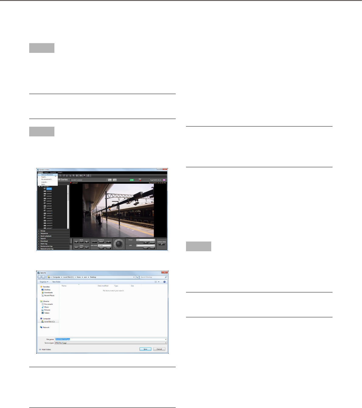
98
99
Step 1
Display the image to be saved.
Refer to the "Monitor live images" section ( +
page 45) or the "Playback" section (+ page 67)
for how to display images.
Note:
Saving is available only when displaying images •
on a 1-screen.
Step 2
Select "Save as JPEG file(S)..." under "File(F)" on the
menu bar or click the [Save as JPEG file] icon on the
tool bar.
The "Save As" window will be displayed.
Note:
The "Save As" window can be opened by select-•
ing "Save as JPEG file..." from the pop-up menu
displayed by right-clicking on the image display
area.
The following are descriptions about each item dis-
played on the "Save As" window.
n Save in:
Specify a folder as the destination of the file to be
saved.
n File name:
Enter the name of the file to be saved. The default
name is as follows.
Example: 20061008110340.jpg (time & date when the
file is saved:
Note:
When the time & date are not displayed on the •
status bar, time & date part of the default file
name will be determined according to the current
time of the PC.
n [Save] button
The "Save As" window will close and the image will
be saved as a JPEG file and stored in the selected
folder.
n [Cancel] button
The "Save As" window will close without saving.
Step 3
Click the [Save] button after specifying a destination
folder and the file name.
The image will be saved as a JPEG file with the
specified name and stored in the specified folder.
Note:
The image to be saved is the image displayed in •
step 2.
Save as a JPEG file
It is possible to save the live image or recorded images as a JPEG file.
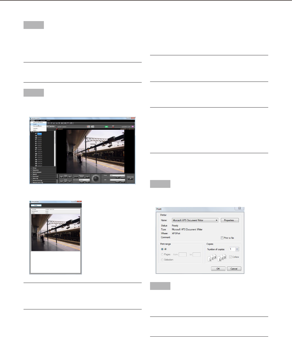
100
101
Print
It is possible to print an image of live images or recorded images.
Step 1
Display the image to be printed.
Refer to the "Monitor live images" section ( +
page 45) or the "Playback" section (+ page 67)
for how to display images.
Note:
Printing is available only when displaying images •
on a 1-screen.
Step 2
Select "Print(P)..." under "File(F)" on the menu bar or
click the [Print] icon on the tool bar.
The "Print Preview" window will be displayed.
Note:
The "Print Preview" window can be opened by se-•
lecting "Print..." from the pop-up menu displayed
by right-clicking on the image display area.
The following are descriptions about each item dis-
played on the "Print Preview" window.
n [Print...] button
The "Print" window will be displayed.
n Time & date
Time & date when the file is printed will be displayed.
The time & date will be followed by an asterisk "*"
when the daylight saving time is applied.
Note:
When the time & date are not displayed on the •
status bar, the current time of the PC will be
printed.
n Recorder/encoder
The recorder title will be displayed.
Note:
When displaying an image from a camera that is •
not registered in the recorder, "--" will be dis-
played.
When displaying an image from an encoder that is •
not registered in the recorder, the encoder title will
be displayed.
n Camera
The camera title will be displayed.
Step 3
Click the [Print...] button.
The "Print" window will be displayed.
Step 4
Click the [OK] button after completing the settings.
Printing of the image currently being displayed
will start.
Note:
The image to be printed is the image displayed in •
step 2.
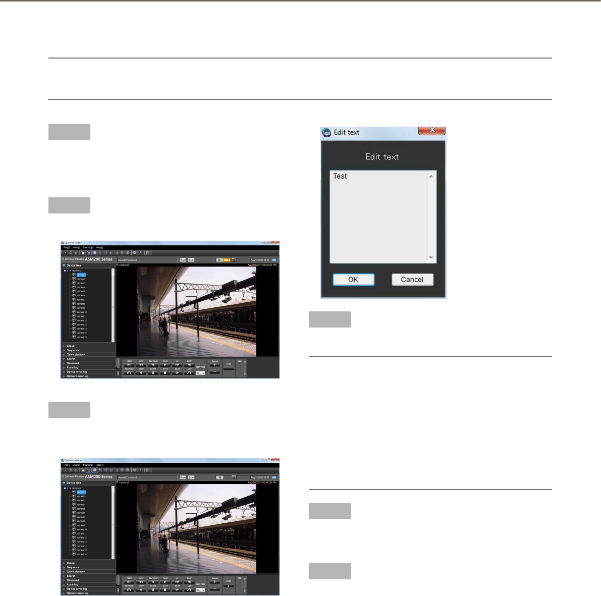
100
101
Display/edit text information
It is possible to attach text information to the recorded images. Up to 200 characters (up to 10 lines) can be
entered.
Note:
Displaying/editing of text information is available only when displaying images on a 1-screen. When display-•
ing images on a multi-screen, the [TEXT] button will not be displayed.
Step 1
Play recorded images on a 1-screen.
Refer to the "Playback" section ( + page 67) for
how to play images.
Step 2
Pause the playback by clicking the [PAUSE] button.
Step 3
Click the [TEXT] button on the playback operation
panel.
Text information of the recorded images will be
displayed.
Step 4
Edit the text information.
Note:
Available characters •
The following characters are available for text in-
formation.
A B C D E F G H I J K L M N O P Q R S T U V W X
Y Z a b c d e f g h i j k l m n o p q r s t u v w x y z
0 1 2 3 4 5 6 7 8 9 ! " # $ % &‘ ( ) * + ,- . / : ; < = >
? @ [ \] ^ _ ` { | } (space)
A break (line feed) can be entered by pressing the •
[Ctrl] key and the [Enter] key simultaneously.
Step 5
Click the [OK] button.
The confirmation window will be displayed.
Step 6
Click the [OK] button.
The edited text will be registered, and the confir-
mation window and the "Edit text" window will
close.
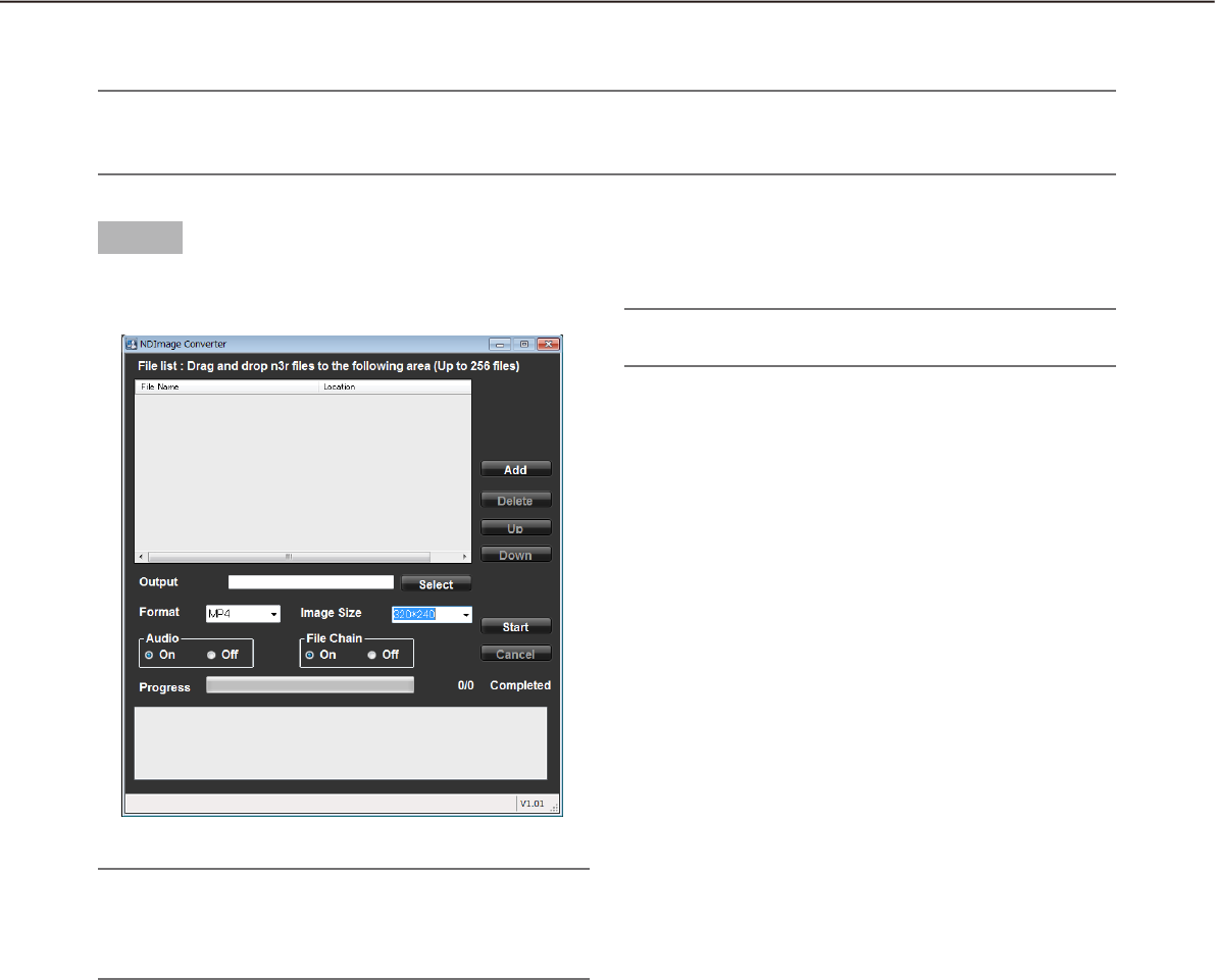
102
103
Convert a file to the standard format
It is possible to convert an n3r file into an mp4 file.
Note:
If the downloaded n3r file is an image data from a device manufactured by other than Panasonic, the file •
conversion will not be supported.
Step 1
Click the [File conversion] icon on the tool bar.
The file conversion window will be displayed.
Note:
When a user who is not allowed to convert a file •
logged in to this software, the [File conversion]
icon will not be displayed.
The details are as follows.
n File Name
Indicates the list of source n3r files.
n Location
Indicates the full paths of source n3r files.
n Output
Indicates the names of the folders to output the con-
verted files.
n [Select] button
Open the folder to output a converted file.
n Format
Select the format of converted image data.
Note:
Currently, only the mp4 format can be specified.•
n Image Size
Select the resolution from the following.
1920 x1080/ 1280x960/ 1280x720/ 960x720/
800x600/ 720x576/ 720x480/ 640x480/ 320x240
n Audio
Select whether or not to load the audio (n3a) file dur-
ing conversion.
On: Load the audio file.
Off: Not to load the audio file.
n File Chain
Select whether or not to combine two or more con-
verted files together.
On: Combine files.
Off: Not to combine files.
n [Add] button
Select a source file.
n [Delete] button
Delete a source file from the list of the files to convert.
n [Up] button
Change the order of listed files to the ascending
order.
n [Down] button
Change the order of listed files to the descending
order.
n [Start] button
Start conversion.
n [Cancel] button
Cancel conversion.
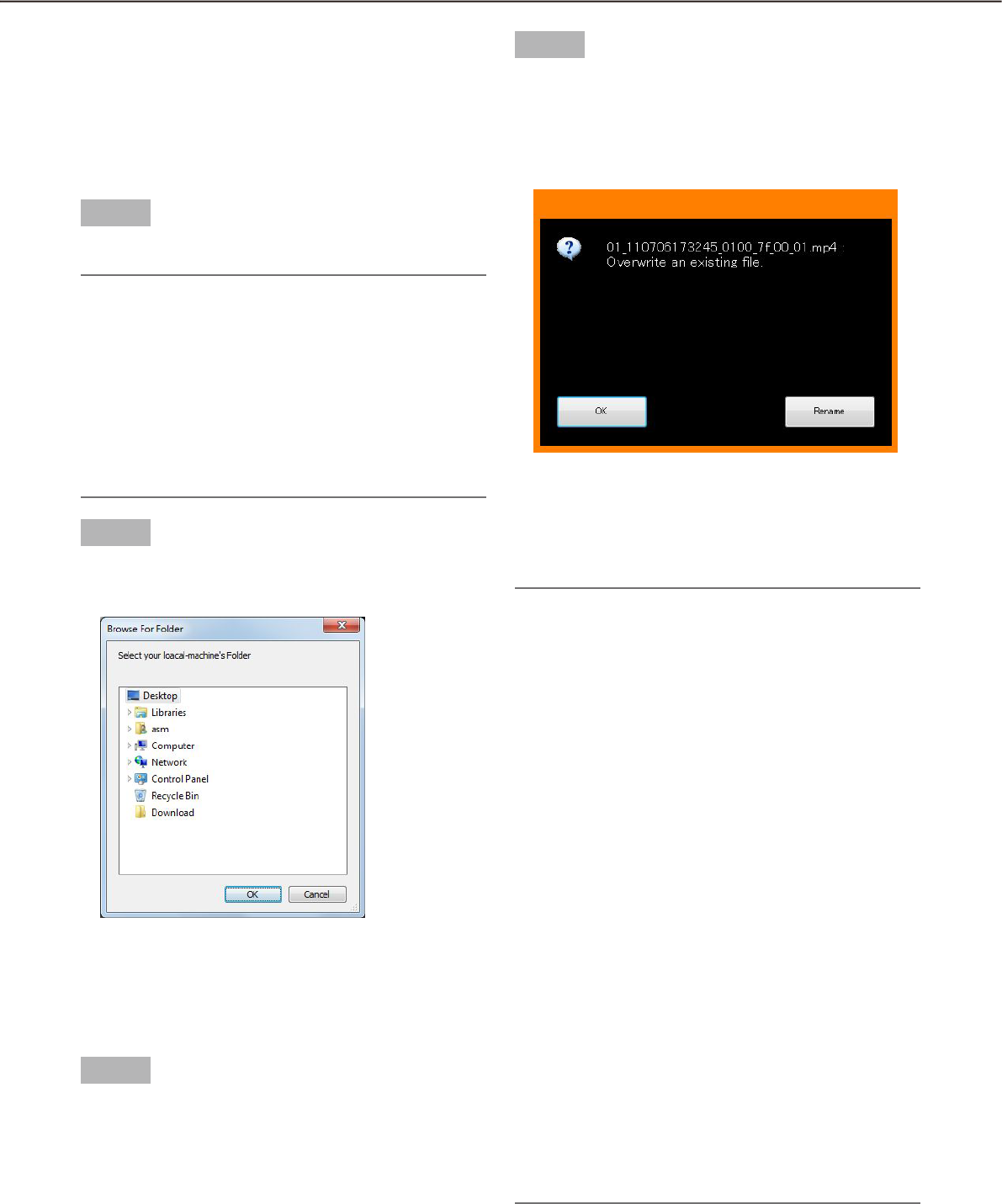
102
103
n Progress bar
The status of the download will be displayed.
n Conversion status
"Number of files converted"/"Number of files to be
converted" will be displayed.
Step 2
Drag and drop the source n3r file into the list of files.
Note:
It is also possible to select the file by clicking the •
[Add] button.
It is impossible to convert h3r files.•
File conversion starts sequentially according to •
the order of the list. To combine two or more con-
verted files together, the content of the source
files should be ordered chronologically. Click the
[Up]/[Down] button to correct the chronological
order.
Step 3
Click the [Select] button to select the destination
folder.
When the [OK] button is clicked, the selected folder
will be displayed as the output destination. When the
[Cancel] button is clicked, output to the selected
folder will be canceled.
Step 4
Select the options of "Image Size", "Audio" and "File
Chain".
Step 5
Click the [Start] button.
File conversion will start. If the name of the con-
verted file is the same as an existing file, the
window will be displayed to select whether or not
to overwrite the existing one.
When the [OK] button is clicked, the file will be over-
written.
When the [Rename] button is clicked, it is possible to
change the file name.
Note:
If selecting a system folder such as "Program •
Files" as an output folder, the file may not be cre-
ated in the selected folder regardless of success-
ful file conversion.
In this case, OS virtualization will create a system
folder and files under;
C:\User\<User name>\AppData\Local\
VirtualStore
Example: When trying to create files in "C:\
Program Files\Panasonic" by a user name "asm",
mp4 files will be created under;
C:\User name\asm\AppData\Local\VirtualStore\
Program Files\Panasonic
The file name will be automatically determined. •
The extension of the file will be changed from
"n3r" to "mp4".
The maximum size of an mp4 file is approx. 1.9 •
GB. When the size exceeds 1.9 GB during conver-
sion, the file will automatically be divided into sev-
eral files. The unique and sequential numbers will
be given to these files.
When the conversion of a file fails in the process, •
it will automatically be converted again into an-
other file. However, the file will automatically be
divided at the point of failure.
When the file conversion error occurs, the details •
will be displayed in the message area.
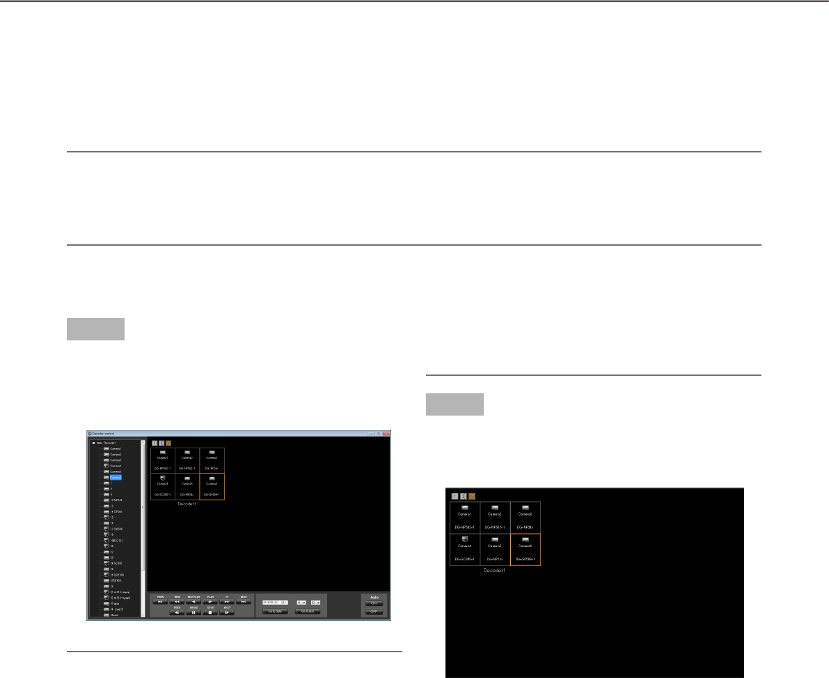
104
105
Control a decoder
Control a decoder
The following operations are available for a registered decoder.
Displaying live images•
Switching the screen pattern•
Playing back the recorded images•
Note:
These functions will become available after the license for the WV-ASE204 is added.•
Depending on the devices connected to the decoder, network status or restrictions of WJ-GXD400, images •
from the decoder may sometimes not be displayed or controlled. Refer to the operating instructions of the
decoder for further information about the restrictions.
Select a decoder
Step 1
Click the [Decoder control] icon on the tool bar, select
"Decoder control(G)…" on the menu bar or select the
decoder (online) icon displayed from the device tree.
The "Decoder control" window will be displayed.
Note:
When the "Decoder control" window is displayed •
for the first time, the display will be conformed to
the downloaded current decoder status. After the
window is displayed once, the current status will
not be downloaded until the window is closed and
displayed again. Therefore, if the "Decoder con-
trol" window has constantly been displayed, the
status displayed on the window may differ from
the actual status of the decoder depending on the
control by another user or network errors. In this
case, close and display the "Decoder control"
window again.
When the "Decoder control" window is displayed •
by clicking the [Decoder control] icon on the tool
bar or by selecting "Decoder control(G)…" on the
menu bar, the first area specified for the decoder
that is displayed at the upper-left will be selected.
The HD300, NV200• , ASR500 or GXD400 icon will
not be displayed in the device tree on the "Device
control" window.
Step 2
Click (Select) the desired area associated with the
desired decoder using a mouse.
The selected frame (in orange) will move.
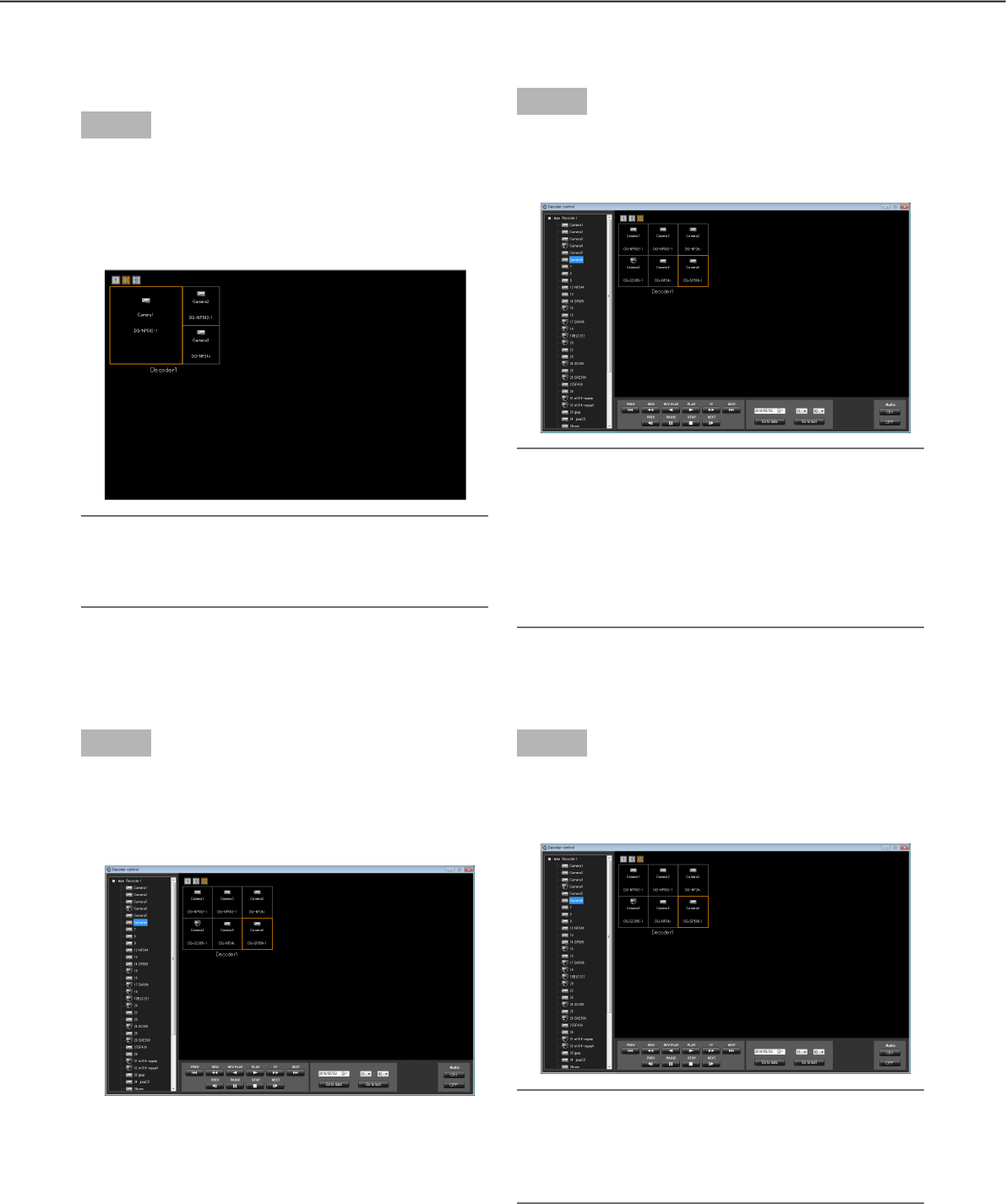
104
105
Start the audio output from the camera
Step 1
Press the [Audio ON] button.
The audio will be output from the selected camera
to the selected decoder.
Note:
It is possible to output the audio from only one •
channel at a time. (The latest output has the prior-
ity.)
When "Unknown" is displayed for the selected •
camera or no camera has been registered for the
selected channel, the [Audio ON] and [Audio OFF]
buttons will not be displayed.
Switch the screen pattern of the
decoder
Step 1
Select the 1-screen, 3-screen or 6-screen icon above
the displayed areas associated with the decoder.
The screen pattern will be switched according to
the selected icon, and the selected icon will turn
orange.
Note:
If the currently selected area disappears when the •
screen pattern is switched, the first area will be
selected with the frame.
Display live images using the decoder
Step 1
Select a camera from the device tree on the "Device
control" window.
Live images will be displayed on the selected area
associated with the selected decoder.
Stop the audio output from the camera
Step 1
Press the [Audio OFF] button.
The audio output from the selected camera will be
stopped.
Note:
When "Unknown" is displayed for the selected •
camera or no camera has been registered for the
selected channel, the [Audio ON] and [Audio OFF]
buttons will not be displayed.

106
107
Display recorded images using the decoder
Step 1
Select the desired area to play back recorded images
associated with the desired decoder.
Playback operation panel will be displayed when
the camera associated with the selected area is
connected to the recorder.
Step 2
Perform one of the following.
Click the [PLAY] button on the playback operation •
panel.
Select the time & date and click the [Go to date] •
button.
Click the [Go to last] button.•
Playback will start on the associated decoder.
Step 3
It is possible to control the following buttons when
the decoder is in the playback status.
[PREV RECORD] button: Playback will start after
skipping to the previous recorded image.
[REW] button: Fast reverse playback will be per-
formed. Playback speed for fast reverse playback
will be changed in the following order each time
this button is clicked: Step2 (Approx.4x)
Step3 (Approx.8x) Step4 (Approx.16x)
Step5 (Approx.32x) Step6 (Approx.48x)
Step7 (Approx.96x)
Note:
The step will not be displayed on the "Device con-•
trol" window. The status will be same as the nor-
mal playback.
[REV PLAY] button: Reverse playback of a
recorded image will be performed.
When playing MPEG-4 or H.264 images, some •
frames of recorded images may not be displayed.
Reverse playback will be performed with the set
refresh interval of the camera.
[REW] button: Fast reverse playback will be per-
formed. Playback speed for fast reverse playback
will be changed in the following order each time
this button is clicked: Step2 (Approx.4x)
Step3 (Approx.8x) Step4 (Approx.16x)
Step5 (Approx.32x) Step6 (Approx.48x)
Step7 (Approx.96x)
The step will not be displayed on the "Device con-•
trol" window. The status will be same as the nor-
mal playback.
This software does not support the fast playback •
smooth mode of the ND400. The playback mode
will be normal fast playback.
[NEXT RECORD] button: Playback or reverse
playback will start after skipping to the next
recorded image.
[PREV IMAGE] button: The previous frame will be
displayed when this button is clicked during paus-
ing.
When playing MPEG-4 or H.264 images, some •
frames of recorded images may not be displayed.
Reverse frame by frame playback will be per-
formed with the set refresh interval of the camera.
[PAUSE] button: Playback will stop when this but-
ton is clicked during playback. Playback will
resume when this button is clicked during paus-
ing.
[STOP] button: Playback will stop and live images
will be displayed.
[NEXT IMAGE] button: The next frame will be dis-
played when this button is clicked during pausing.

106
107
Viewer software
When an image file or an audio file is downloaded, the downloaded file will be saved as an image file (file name.
n3r, file name.h3r) or an audio file (file name.h3a).
The viewer software can be downloaded together with the downloaded image file or audio file. Playback, saving
and printing of the downloaded image file or audio file are available using the viewer software.
Note:
Viewer software to be copied differs depending on the file to be downloaded. •
If the extension of the file is "n3r": n3vsetup.exe
If the extension of the file is "h3r": Viewer.exe•
The images of windows shown below for the following procedures are ND_Viewer.exe.•
Install the viewer software
Note:
When the older version of the viewer software is installed, installation may not be successfully completed. •
Uninstall the older version first before starting the installation.
The "Viewer.exe" is unnecessary to install.•
Step 1
Double-click the downloaded installer file "n3vsetup.
exe".
The installer will be launched. Follow the instruc-
tions displayed on the monitor.
Note:
Read the content of the "License Agreement" win-•
dow and select "I accept the terms in the license
agreement".
It is possible to install the software even when •
"User Name" and "Organization" on the
"Customer Information" screen are blank. Select
"Anyone who uses this computer (all users)".
Select "Complete" for the setup type.•
Step 2
Click the [Install] button.
Installation will start. When the installation is
successfully completed, the installation comple-
tion window will be displayed. Click the [Finish]
button.
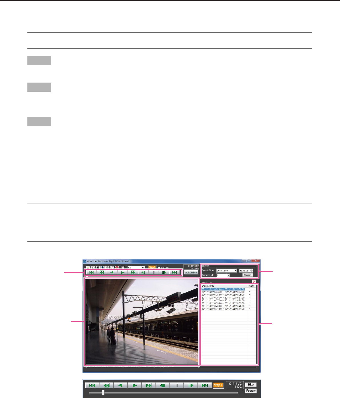
108
109
How to use the viewer software (ND_Viewer)
Note:
Viewer software to be used differs depending on the fi le to be played. •
If the extension of the fi le is "n3r": ND_Viewer.exe
If the extension of the fi le is "h3r": Viewer.exe•
It is impossible to play only an audio fi le (extension:h3a) using the viewer software.•
Uninstall the viewer software
Note:
The "Viewer.exe" is unnecessary to uninstall. Delete the fi le directly.•
Step 1
Open "Programs - Uninstall a program" in "Control Panel" of Windows 7.
Step 2
Select "ND_Viewer" from the presently installed programs and click the [Uninstall] button.
The uninstall program will be launched and the wizard will be displayed.
Step 3
Uninstall the program by following the displayed instructions.
Playback opera-
tion button
Image display area
Search box
List display area
Playback operation window when images are displayed on a full screen
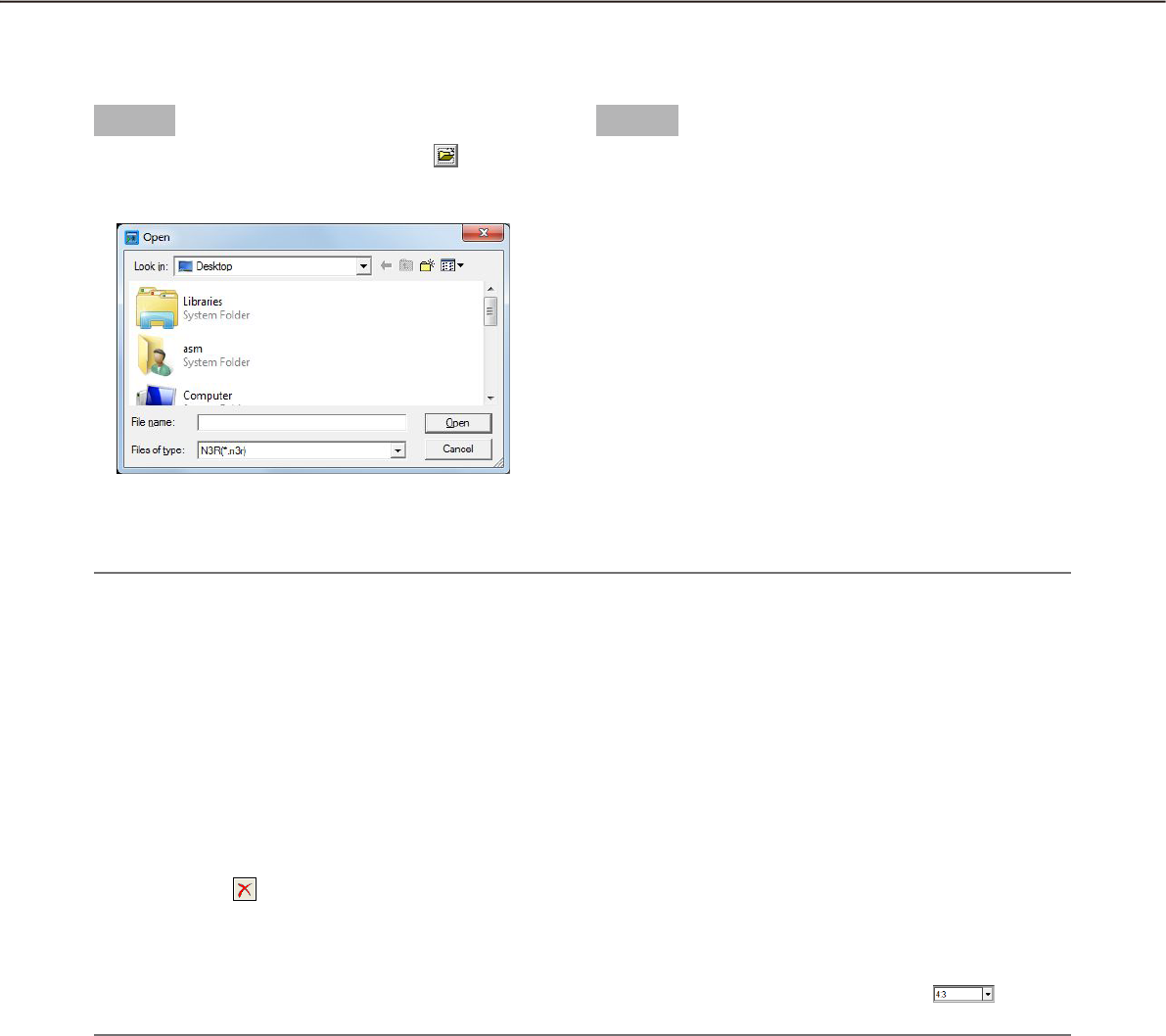
108
109
Step 1
Start the viewer software and click the button.
The "Open" window will be diplayed.
Step 2
Select the desired download file (file extension:n3r)
and click the [Open] button.
Or drag and drop the image data file into the viewer
software without displaying the "Open" window.
The information of the selected file will be dis-
played in the list display area.
Date & Time: Indicates a start time and an end
time for copying the recorded images.
Cam: Indicates the camera number.
Note:
Do not change the file name of the copied or downloaded image data. If the file name is changed, the file in-•
formation will not be displayed correctly.
It is possible to select multiple files (up to 100 files) by clicking the desired files while holding down the [Ctrl] •
key or the [Shift] key on the user keyboard and display all of them in a list by drag & drop.
The files can be sorted by start time and date in ascending or descending order by clicking the header of •
the list display area.
To add image data to the list display area, right-click the list and select [Add file] from the menu displayed. •
When the window for opening files is displayed, proceed to Step 2. The image data added will be displayed
on the sorted list.
When the number of displayed image data files has reached 100, no more files can be added. The total •
number of selected image data files is displayed under [Total:] on the list.
Clicking the • button will delete all data displayed on the list. Another way to clear the list is to right-click
the list and select [Clear all list].
When there is a data in the same directory as the viewer software or the "data" folder in the same directory, •
the data will automatically be loaded for playback.
It is possible to change the aspect ratio of the image display area by selecting the ratio from • . Select
the setting in accordance with the aspect ratio and the image capture size of the image data.
Select recorded images currently being played
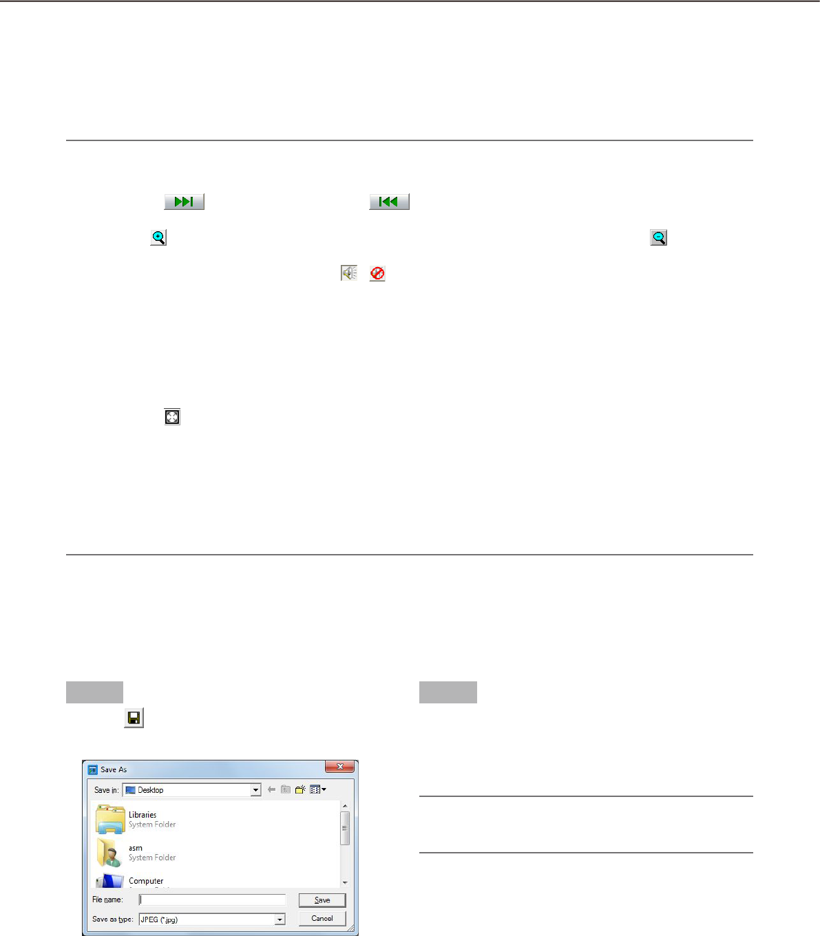
110
111
Playback of recorded images
Use the playback operation button to play downloaded images. If an image from the same camera is displayed
on the list, the next image in playback mode or the previous image in reverse playback mode will be played
back consecutively. If the same camera channel is absent on the list, playback will stop, the image display area
will turn black and the unit is paused.
Note:
When starting playback of password protected data, the password entry screen will be displayed. Enter the •
current password correctly.
Clicking the • button in playback (or the button in reverse playback) will play the next (or previ-
ous) image on the list of the camera whose image is currently being played back.
When the • button is clicked, the displayed image will be enlarged two times. Clicking the button will
reset the image to its original size.
If there is audio data (file name .n3a), the • / buttons will be displayed. Click these buttons to play back
with or without audio.
When this software and the viewer software are running at the same time, audio may not be played prop-•
erly. To play audio correctly, use either of them and close the other.
Playback images and audio may sometimes not be synchronized exactly.•
When the [Search] button is clicked after selecting [Date &Time] and [Camera(ch)] in the search box, play-•
back of the image data of the selected camera data will start from the top of the data corresponding to the
selected time and date.
Clicking the • button will display the image on a full screen. Clicking the [Restore] button on the operation
window or pressing the [Esc] key on the keyboard will return the image display to the previous status.
When performance of the PC in use is low, images may not be played smoothly.•
To play image data together with audio data, click the [Audio ON] button. (When using Viewer.exe)•
It is impossible to play audio when no sound card is installed on the PC. (When using Viewer.exe)•
Clicking the [Hide] button or right-clicking the mouse can hide the playback operation window.•
Mark the "Smooth" checkbox to display the fast playback images more smoothly. The fast playback speed •
may be limited depending on the performance of the PC in use or process status.
Save the downloaded image as a JPEG file
It is possible to save the paused image as a jpeg file (extension: jpg). Saving the downloaded file is available
only when the image is paused.
Step 1
Click the button.
The "Save As" window will be displayed.
Step 2
Enter the file name and select "JPG (*.jpg)" for "Save
as type".
Designate the folder and click the [Save] button.
The paused image will be saved as a JPEG file.
Note:
When using Viewer.exe, it is possible to save as a •
bitmap file by selecting "BMP (*.bmp)".

110
111
Save image data (copy) (ND_Viewer only)
Save selected image data (file name.n3r) in any folder on the PC.
Step 1
Right-click the list and select [Copy] from the menu displayed.
The "Save As" window will be displayed. →
Step 2
Click the [Save] button after specifying a destination folder and the file name.
The image data will be saved as a JPEG file. →
Note:
It is not possible to operate the viewer software while copy is in progress.•
Print the downloaded image
Print the image displayed in the image display area.
Pause playback at the desired point and click the button. When printing the image of an n3r file, time & date
when the image is paused will be printed together.
Note:
When using Viewer.exe, it is possible to select a print size from L/M/S.•
Alteration detection
It is possible to detect the alteration of the data if a code for the alteration detection has been attached to the
downloaded data.
The [ALT CHECK] button will be displayed only when opening a file with a code for the alteration detection.
Clicking the button starts alteration detection and displays the result in a window.
OK (Not Altered): No alteration was detected.
NG (Altered): Alteration was detected.
Display Single/Quad PTZ image converted from fisheye images
The function that can convert fisheye images from the fisheye camera into Single/Quad PTZ images is available
(conversion function).
Important:
To use the conversion function, download the conversion library from the following URL and install it on the •
PC on which the viewer software is used.
http://security.panasonic.com/pss/security/support/info.html
Refer to the provided leaflet "To customers using the extensive options for Fisheye network cameras" for in-•
formation about the compatible models.
When the conversion function is applicable to the selected image, / / buttons will be displayed.
Click and select the conversion format.
Note:
Clicking the • button will reset the concerted image to the original fisheye image.
Clicking the • button will convert the fisheye image to a Single PTZ image.
Clicking the • button will convert the fisheye image to a Quad PTZ image.
When clicking on an image that is converted into a Single/Quad PTZ image, the image will be displayed •
while locating the clicked point at the center of the screen.

112
113
Alarm/event notification and management of logs
A pop-up window (notification window) will be displayed on the operation window when an alarm or an error
occurred.
Alarm notification: Message provided from the sensor or the camera, etc.
Event notification: Message notifies of an error occurrence such as a recorder error or a network error
Important:
It is necessary to configure the settings of a device to be used in order to use the alarm/event notification •
function.
When also using the Panasonic alarm protocol function of the recorder, it is necessary to set the same •
number to the event action number and the recording camera number on the recorder.
Refer to the operating instructions of the recorder for how to configure the settings.
Note:
Only when an event is a terminal alarm, it is unnecessary to set the same number to the terminal number •
and the recording camera number since the information of the recording camera configured for the terminal
alarm setting on the recorder is used. Refer to the operating instructions of the recorder in use for how to
configure the terminal alarm settings.
When the recorder in use is the HD600, it is possible to select two or more recording cameras. The camera •
whose number is the smallest is used for this software.
When the terminal alarm setting has been changed on the recorder, it is necessary to download the informa-•
tion from the recorder. In addition, if the information of the data in use has been downloaded from the re-
corder using WV-ASM100/WV-ASM100L (Version 7 or earlier), it is necessary to download the information
from the recorder again. Refer to WV-ASM200 Setup Instructions (PDF) for how to download the informa-
tion. Live images from the camera in which an alarm occurred can be displayed only when the login user is
allowed to access this camera.
Live images from the camera in which an alarm occurred can be displayed only when the login user is al-•
lowed to access this camera.
Images recorded at an alarm occurrence can be played only when a login user is not restricted by the user •
level determined by the administrator to play the recorded images.
When an alarm/event notification is provided, one of the following logs will be filed.
Alarm log: A log that contains alarm information transmitted from the device using Panasonic alarm
protocol
Device error log: A log that contains device error information transmitted from the device using Panasonic
alarm protocol
Network error log: A log that contains information of a network error that occurred between this software and
the device
Note:
Refer to the WV-ASM200 Setup Instructions (PDF) for further information about the logs.•
Alarm/event notification window
When an alarm/error occurred, descriptions of the alarm/error occurrence will be displayed in a pop-up window
(notification window) on the operation window. The notification window will be displayed at the bottom right of
the operation window. When there are two notification windows, the upper notification window is the newer one
and the lower one is the older one.
When the lower message window displayed is closed, the upper message window moves to the position where
the lower message window had been displayed.
Note:
When a same type of alarm/event occurred while the message window is being displayed, the descriptions •
in the message window will be renewed.
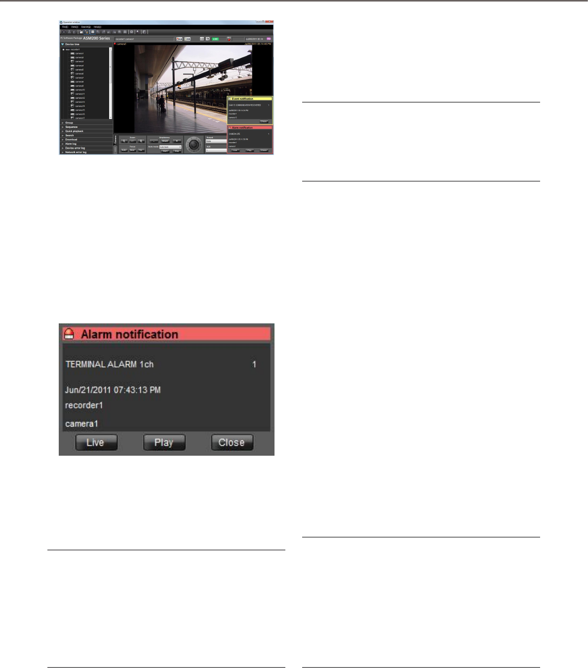
112
113
n Alarm notification message
Notifies of an alarm occurrence.
n Event notification message
Notifies of an event occurrence.
Note:
When an alarm/event occurred during the sub •
window such as the "Search" window is dis-
played, the buttons on the displayed message
window are inoperable until the displayed sub
window is closed.
"Alarm notification" window
When an alarm occurred, the "Alarm notification" window will be displayed. When an alarm occurred, the alarm
buzzer will start sounding and the "Alarm notification" window will be displayed. When the "Alarm notification"
window is closed, the "Alarm log" panel will be displayed. When an alarm notification is provided from the
recorder during the "Alarm notification" window is displayed, the descriptions in the notification message win-
dow will be renewed and the latest alarm information will be displayed.
n Alarm notification message
Alarm information, time & date of the alarm occur-
rence, the title of the recorder/encoder (that provided
the notification) and the title of the camera will be dis-
played.
Note:
When the device that provided an alarm notifica-•
tion is a camera, "--" will be displayed as the title
of the device. However, when a Fisheye camera is
specified as the device to provide the notification
and "Quad streams" is selected for the setting,
the title of the camera will be displayed instead of
the recorder/encoder and the channel title will be
displayed instead of the camera title.
n Number of alarm occurrences
Total number of the alarm occurrences will be dis-
played. When the total number of the alarm occur-
rences exceeds 1000, the "1000<" indication will be
displayed.
n [Live] button
The "Alarm notification" window will close and live
images from the camera in which the alarm occurred
will be displayed on a 1-screen.
n [PLAY] button
The "Alarm notification" window will close and play-
back of recorded images on a 1-screen will start from
the point of 5 seconds before the alarm occurrence.
Note:
When it is just after the alarm occurrence, play-•
back may not start from the point of 5 seconds
before the alarm occurrence.
Depending on the settings of the recorder, play-•
back may not start from the point of 5 seconds
before the alarm occurrence.
When an alarm notification is provided from an •
encoder or a camera that is not registered in the
recorder, the [PLAY] button will not be displayed.
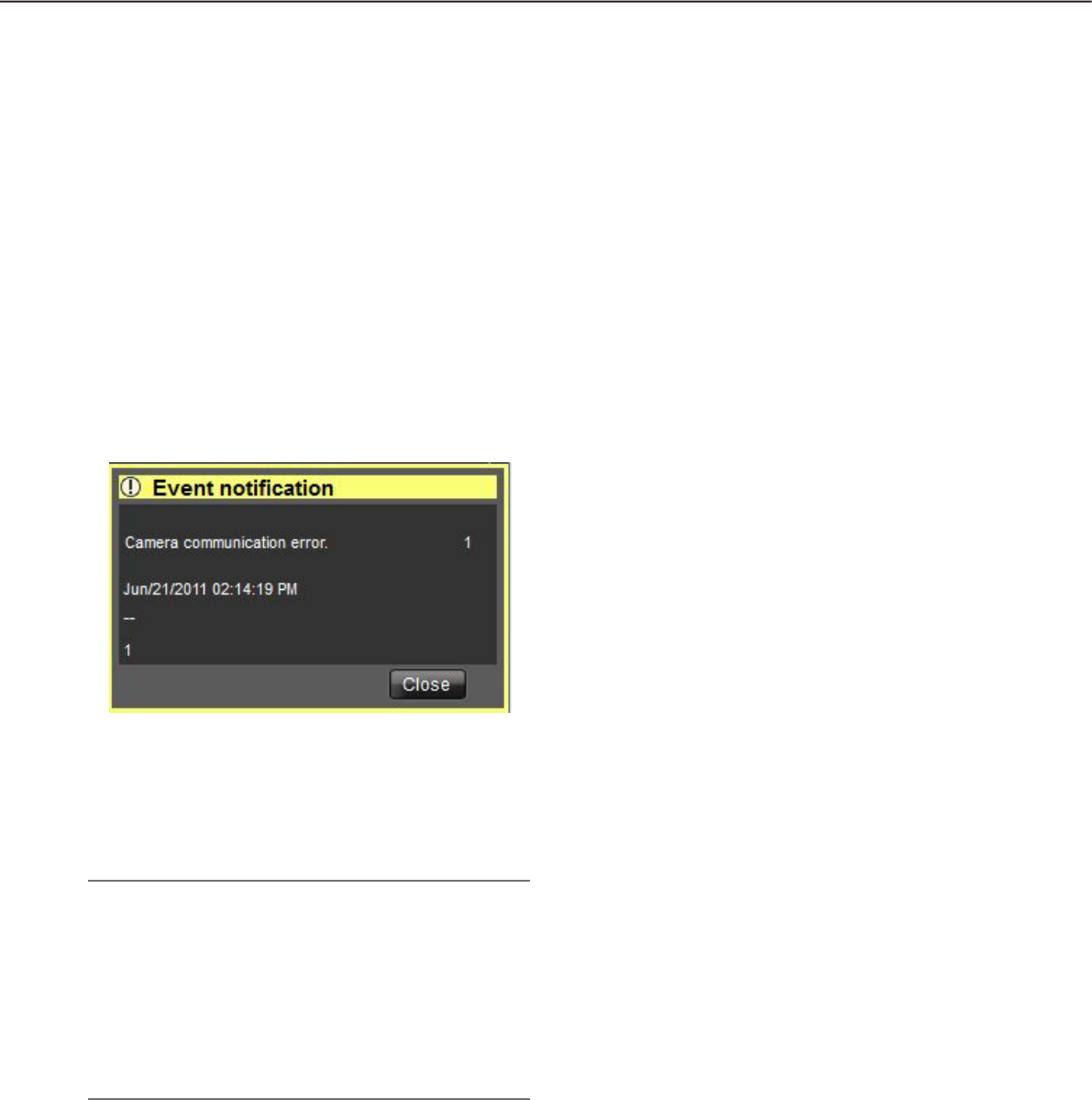
114
115
Event notification message window
The error notification message window provides notification of a device error or a network error occurrence.
When an error occurred, the alarm buzzer will start sounding and the error notification message window will be
displayed. When the error notification message window is closed, the "Device error log" panel or the "Network
error log" panel will be displayed.
When an event notification is provided from the recorder during the event notification message window is dis-
played, the descriptions in the notification window will be renewed and the latest event information will be dis-
played.
n Event log
Error information, time & date of the error occurrence,
the title of the recorder/encoder (that provided the
notification) and the title of the camera will be dis-
played.
Note:
When the device that provided an error notifica-•
tion is a camera, "--" will be displayed as the title
of the device. However, when a Fisheye camera is
specified as the device to provide the notification
and "Quad streams" is selected for the setting,
the title of the camera will be displayed instead of
the recorder/encoder and the channel title will be
displayed instead of the camera title.
n Number of error occurrences
Total number of the error occurrences will be dis-
played. When the total number of the error occur-
rences exceeds 2000, the "2000<" indication will be
displayed.
n [Close] button
The error notification message window will close. The
"Alarm log" panel will be displayed when the alarm
notification message window is closed.
n [Close] button
The error notification message window will close. The
"Device error log" panel or the "Network error log"
panel will be displayed when the error notification
window is closed.
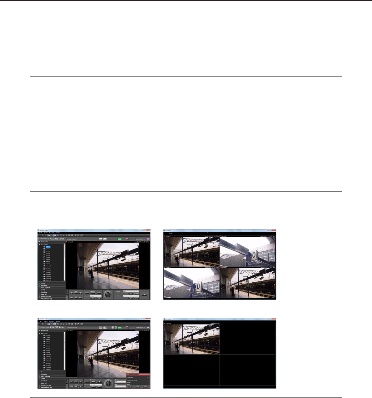
114
115
Alarm mode of the live window
When the Live window is active and "ON" is selected for "Alarm camera direct live window", the live window
will be switched into the alarm mode and display live images from the camera in which the alarm occurred
when receiving an alarm notification.
The live window will automatically be in the alarm mode when an alarm notification is provided regardless of the
current operation (sequence display, group display, minimized, full screen display) of the live window.
Note:
Live images will be displayed on a screen selected for the "Number of alarm camera direct live window" set-•
ting (1-screen/4-screen/9-screen/16-screen/25-screen/36-screen/49-screen/64-screen) on the [Alarm] tab
of the "Alarm" page when the live window is in the alarm mode. Only an administrator can configure the
"Number of alarm camera direct live window" setting. Refer to the WV-ASM200 Setup Instructions (PDF) for
further information.
When the number set for the "Number of alarm camera direct live window" setting on the [Alarm] tab of the •
"Alarm" page is more than the number set for "Live window (multi-screen) with the maximum number of
areas", the number set for "Live window (multi-screen) with the maximum number of areas" will be applied.
Only an administrator can configure the "Live window (multiscreen) with the maximum number of areas"
setting. Refer to the WV-ASM200 Setup Instructions (PDF) for further information.
When the live window is not opened, the alarm camera direct live window function will not be performed.•
Even after the license for the WV-ASE202 is added and while more than one live window are being dis-•
played, the alarm camera direct live window function will be performed only on a Live window (1).
When the live window is active
•Normaloperation
•Alarmstatus
Note:
The display position and the window size of the live window when it is started will be the same as of the last •
time the live window is closed.
When the set time (auto reset wait time) has passed after the live window shifted into the alarm mode, the •
live window returns to the previous operation. Only an administrator can configure the "Auto reset wait time"
setting. Refer to the WV-ASM200 Setup Instructions for further information about the "Auto reset wait time"
setting.
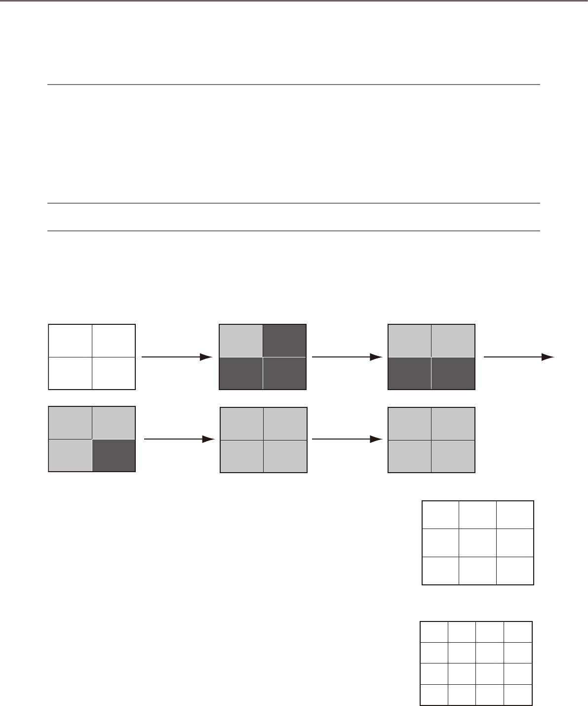
116
117
When alarms occurred sequentially before the alarm is reset automatically, live images from the cameras •
will be displayed in from the upper left area in order. When the number of alarm occurrences exceeds the
maximum number of areas ("Number of alarm camera direct live window"), live images of the older alarm
will be canceled and live images of newer alarm will be displayed in order (live images displayed in the
upper left area will be the first to be canceled).
Simultaneously display live images of two or more alarms when alarms occurred
sequentially
Depending on a screen selected for the "Number of alarm camera direct live window" setting (1-screen/4-
screen/9-screen/16-screen/25-screen/36-screen/49-screen/64-screen) on the [Alarm] tab of the "Alarm" page,
live images will be differently displayed as follows. When "1-screen" is selected, live images will be sequentially
displayed in the order of the alarm occurrences.
Note:
25-screen or more will become available after the license for the WV-ASE202 is added.•
When "4-screen" is selected for the "Number of alarm camera direct live window" setting on the
[Alarm] tab
Live images will be displayed as follows. When the number of alarm occurrences exceeds 9, live images of the
older alarm will be canceled and live images of newer alarm will be displayed in order (live images displayed in
the upper left area will be the first to be canceled).
When "16-screen" is selected for the "Number of alarm camera
direct live window" setting on the [Alarm] tab
Live images will be displayed as follows. When the number of alarm occur-
rences exceeds 16, live images of the older alarm will be canceled and live
images of newer alarm will be displayed in order (live images displayed in
the upper left area will be the first to be canceled).
When "9-screen" is selected for the "Number of alarm camera
direct live window" setting on the [Alarm] tab
Live images will be displayed as follows. When the number of alarm occur-
rences exceeds 9, live images of the older alarm will be canceled and live
images of newer alarm will be displayed in order (live images displayed in
the upper left area will be the first to be canceled).
3
1
5
9
13
2
6
10
14
3
7
11
15
4
8
12
16
1 2
3 4
1 2
3 4
1 2 3
4 5 6
7 8 9
1 1 2
5 2
3 4
1 2
3
1
5
9
13
2
6
10
14
3
7
11
15
4
8
12
16
1 2
3 4
1 2
3 4
1 2 3
4 5 6
7 8 9
1 1 2
5 2
3 4
1 2
3
1
5
9
13
2
6
10
14
3
7
11
15
4
8
12
16
1 2
3 4
1 2
3 4
1 2 3
4 5 6
7 8 9
1 1 2
5 2
3 4
1 2
Black
screen
Black
screen
Black
screen
Black
screen
Black
screen
Black
screen
Alarm 1
occurred
Alarm 4
occurred
Alarm 2
occurred
Alarm 5
occurred
Alarm 3
occurred

116
117
When "25-screen" is selected for the "Number of alarm camera
direct live window" setting on the [Alarm] tab
Live images will be displayed as follows. When the number of alarm occur-
rences exceeds 25, live images of the older alarm will be canceled and live
images of newer alarm will be displayed in order (live images displayed in
the upper left area will be the first to be canceled).
76 8 9 10
21 3 4 5
1211 13 14 15
1716 18 19 20
2221 23 24 25
When "36-screen" is selected for the "Number of alarm camera
direct live window" setting on the [Alarm] tab
Live images will be displayed as follows. When the number of alarm occur-
rences exceeds 36, live images of the older alarm will be canceled and live
images of newer alarm will be displayed in order (live images displayed in
the upper left area will be the first to be canceled).
87 9 10 11 12
1413 15 16 17 18
2019 21 22 23 24
2625 27 28 29 30
3231 33 34 35 36
21 3 4 5 6
When "49-screen" is selected for the "Number of alarm camera
direct live window" setting on the [Alarm] tab
Live images will be displayed as follows. When the number of alarm occur-
rences exceeds 49, live images of the older alarm will be canceled and live
images of newer alarm will be displayed in order (live images displayed in
the upper left area will be the first to be canceled).
98 10 11 12 13 14
1615 17 18 19 20 21
2322 24 25 26 27 28
3029 31 32 33 34 35
3736 38 39 40 41 42
4443 45 46 47 48 49
21 34567
When "64-screen" is selected for the "Number of alarm camera
direct live window" setting on the [Alarm] tab
Live images will be displayed as follows. When the number of alarm occur-
rences exceeds 64, live images of the older alarm will be canceled and live
images of newer alarm will be displayed in order (live images displayed in
the upper left area will be the first to be canceled).
1
17
33
49
3
19
35
51
5
21
37
53
7
23
39
55
9
25
41
57
11
27
43
59
13
29
45
61
15
31
47
63
2
18
34
50
4
20
36
52
6
22
38
54
8
24
40
56
10
26
42
58
12
28
44
60
14
30
46
62
16
32
48
64
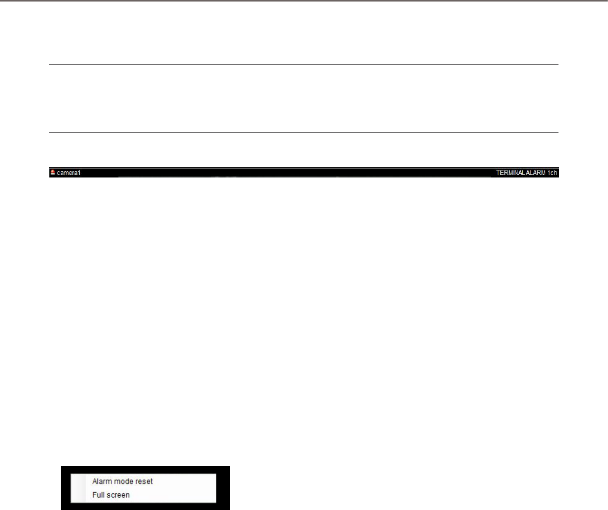
118
119
Information display area
When the live window is in the alarm mode, alarm information will be displayed in the information display area.
Note:
When the live window is in the alarm mode, the group information display area will be hidden and the cam-•
era information display area will be displayed regardless of the settings.
When the live window returns to the normal mode from the alarm mode, the group information display area •
and the camera information display area will be displayed/hidden according to the settings.
n Alarm mode reset
The live window will returns to the previous operation
mode.
n Full screen
The live window in the alarm mode can be displayed
on a full screen.
n Alarm icon
The alarm icon window will be displayed when the live window is in the alarm mode.
n Camera
The title of the camera in which the alarm occurred will be displayed.
n Descriptions of the alarm
Alarm type and the camera channel will be displayed.
Reset the alarm mode
When the set time (auto reset wait time) has passed after the live window shifted into the alarm mode, the live
window returns to the previous operation. When an alarm occurred before the alarm is reset automatically, the
live window will be in the alarm mode until the set time has passed from the moment when the new alarm has
occurred. When alarms occurred sequentially, the alarm mode will continue until the set time has passed from
the moment when the newest alarm has occurred.
When "Alarm mode reset" is selected from the pop-up menu displayed by right-clicking on the image display
area, the alarm mode can be reset even when the set time has not passed yet.
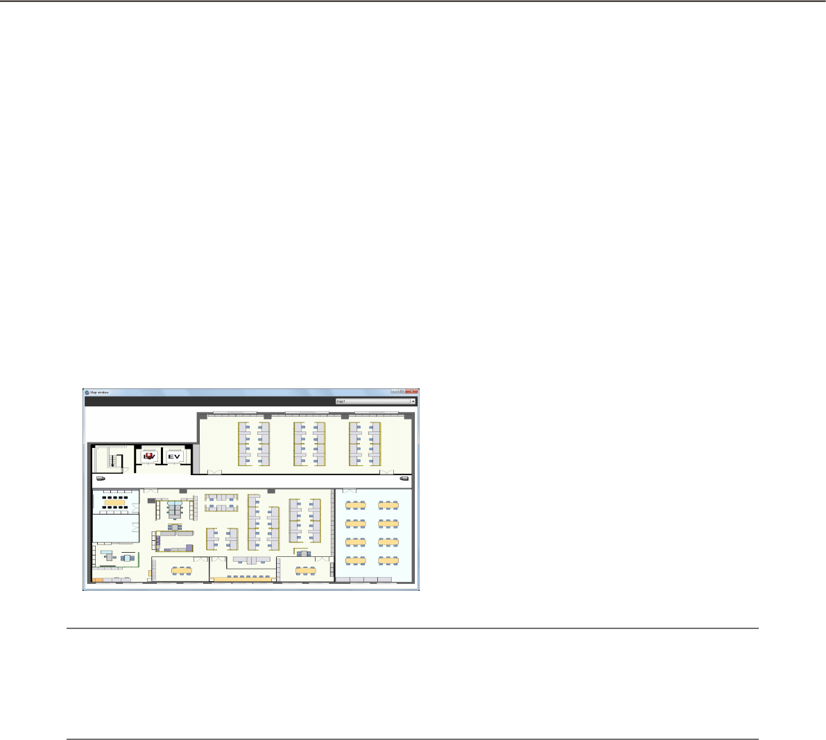
118
119
Emergency recording input alarm
In the state of emergency, emergency recording will sometimes be performed manually using the external
switch.
In this case, the emergency recording input alarm will be notified. An emergency recording input alarm usually
contains information of multiple channels, and they will be filed as logs in the "Alarm log" panel. However, only
the information of the biggest channel number will be displayed in the "Alarm notification" window.
Alarm mode of the map window
When receiving an alarm, the icon of the camera in which an alarm occurred will blink red. The camera icon will
start blinking red for 10 seconds and then displayed in red without blinking. When the icon displayed in red (or
blinking red) is clicked, live images from the camera will be displayed in the selected area of the operation win-
dow and the camera icon will return to the normal camera icon.
The map operation may vary depending on the setting for "Auto change of map".
ON: Change the display to the map that has registered the camera in which an alarm occurred.
OFF: Does not change the display to the map that has registered the camera in which an alarm occurred.
Note:
When alarms occurred sequentially (within less than 1 second), the map will not be changed even if "ON" is •
selected for "Auto change of map".
When the [Live] button or the [Play] button on the • "Alarm notification" window is clicked, images from the
corresponding camera will be displayed and the respective camera icon that has been displayed in red or
blinking red will return to the normal camera icon.
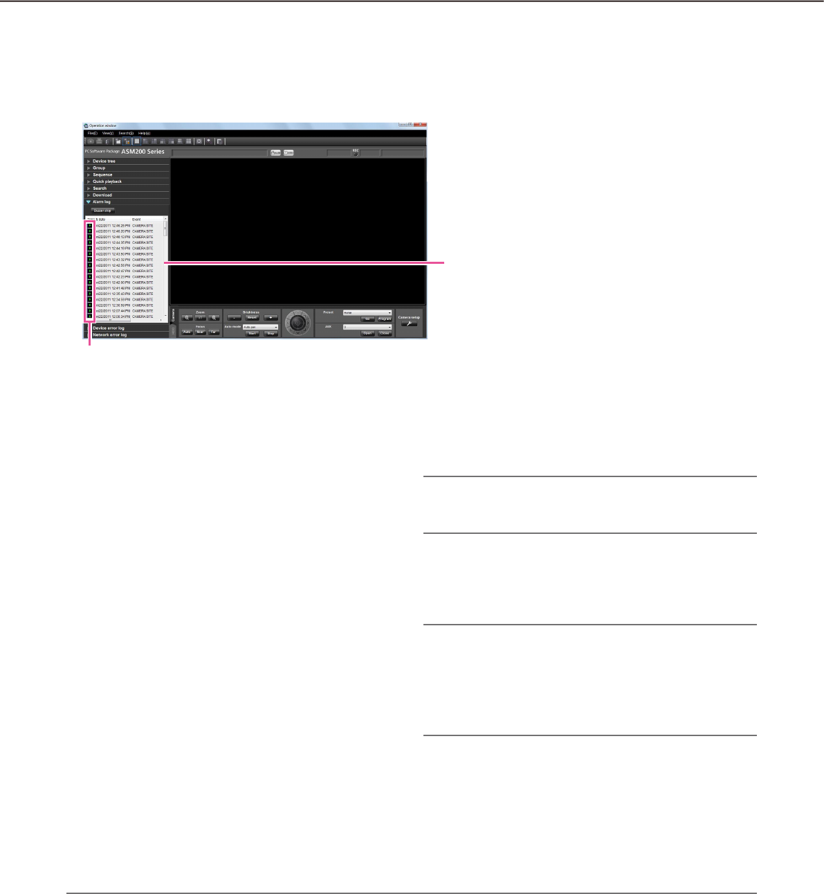
120
121
"Alarm log" panel
When an alarm occurred, the description of the alarm will be filed as a log in the "Alarm log" panel.
Up to 1000 logs will be displayed in the alarm log panel.
n [Buzzer stop] button
The buzzer sounding to announce an alarm or error
will be stopped.
n Alarm log list
Descriptions of the notified alarms will be displayed in
list form. Up to 1000 descriptions will be displayed.
n [Play] icon
Recorded images relating to a log can be played
when this icon is displayed next to a log.
n Time & date
Time & date when the alarm occurred will be dis-
played. The time & date will be followed by an aster-
isk "*" when the daylight saving time is applied.
n Event
Description of the alarm will be displayed.
n Recorder/encoder
The title of the recorder/encoder in which the alarm
occurred will be displayed.
Note:
When the device in which an alarm occurred is a •
camera, "--" will be displayed.
n Camera
The title of the camera in which the alarm occurred
will be displayed.
Note:
When a log with the [Play] icon in the alarm log list •
is clicked, playback of recorded images will start
on a 1-screen. Playback will not start when the
[Play] icon is not displayed next to the alarm log.
The alarm log list will be kept updated.•
Playback from the alarm log list
When the desired alarm log is clicked, recorded images from the camera connected to the recorder in which
the alarm occurred will be played on a 1-screen.
Note:
Playback from the alarm log list will start from the point 5 seconds before the alarm occurrence.•
Depending on the settings of the recorder, playback may not start from the point of 5 seconds before the •
alarm occurrence.
Alarm log list
Play icon
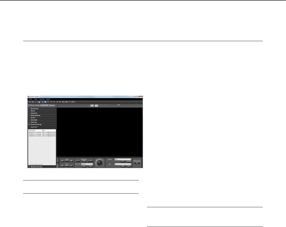
120
121
The [Play] icon will not be displayed in the following cases.•
The login user is not allowed to access the camera.•
The login user is not allowed to play recorded images.•
The listed recorder or camera is removed from the system.•
An alarm notification is provided from an encoder or a camera that is not registered in the recorder.•
Note:
The device error log list will be kept updated.•
n [Buzzer stop] button
The buzzer sounding to announce an alarm or error
will be stopped.
n Device error log list
Descriptions of the notified errors will be displayed in
list form. Up to 1000 descriptions will be displayed.
n Time & date
Time & date when the device error occurred will be
displayed. The time & date will be followed by an
asterisk "*" when the daylight saving time is applied.
n Event
Description of the device error will be displayed.
n Recorder/encoder
The title of the recorder/encoder in which the device
error occurred will be displayed.
Note:
When the device in which a device error occurred •
is a camera, "--" will be displayed.
n Camera
The title of the camera in which the device error
occurred will be displayed.
"Device error log" panel
When a device error occurred, the description of the error will be filed as a log in the "Device error log" panel.
Up to 1000 logs will be displayed in the device error log panel.
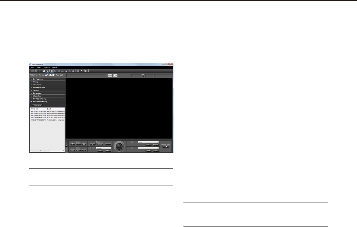
122
123
Note:
The network error log list will be kept updated.•
n [Buzzer stop] button
The buzzer sounding to announce an alarm or error
will be stopped.
n Network error log list
Descriptions of the notified errors will be displayed in
list form. Up to 1000 descriptions will be displayed.
n Time & date
Time & date when the network error occurred will be
displayed. The time & date will be followed by an
asterisk "*" when the daylight saving time is applied.
n Event
Description of the network error will be displayed.
n Recorder/encoder
The title of the recorder/encoder in which the network
error occurred will be displayed.
Note:
When the device in which a network error oc-•
curred is a camera, "--" will be displayed.
n Camera
The title of the camera in which the network error
occurred will be displayed.
"Network error log" panel
When a network error occurred, the description of the error will be filed as a log in the "Network error log"
panel.
Up to 1000 logs will be displayed in the network error log panel.

122
123
Troubleshooting
Before asking for repairs, check the symptoms with the following table.
Contact your dealer if a problem cannot be solved even after checking and trying the solution in the table or a
problem is not described below.
Important:
When the settings of the setup menu of the device are edited, download device information again. •
Otherwise, some functions may not work correctly.
Refer to the WV-ASM200 Setup Instructions (PDF) for further information about download of the device in-•
formation.
Symptom Cause/solution Ref. pages
No live image is
displayed.
Isn’t the event notification window displayed? •
Confirm the displayed description and contact the
administrator.
–
Isn’t "OFF" selected for "MPEG-4 transmission" or "H.264 •
transmission" on the setup menu of the camera in use?
Select "ON" for "MPEG-4 transmission" or "H.264
transmission". Refer to the operating instructions of the camera
for how to configure the settings for MPEG-4 transmission.
–
The recorder is currently being configured using "HDD DISK •
MENU", or the SD memory recording is being performed.
Live images will be displayed when the configuration or the SD
memory recording is completed.
–
It may be necessary to format the hard disk of the recorder. •
Check the status of the recorder by accessing directly to the
recorder from the web browser.
–
It may be possible that the exceptional settings of Windows •
Firewall are not configured.
Configure the exceptional settings of Windows Firewall.
Setup Instructions
(PDF)
Live image is not being
refreshed.
Both images and the displayed time & date are not being •
refreshed.
Connection between the recorder and the camera may be
disconnected or a network trouble may be occurred. Check the
connection.
–
No image is displayed
when the sequence
display is being
performed.
This may occur when MPEG-4 or H.264 images are used in the •
sequence display.
Set the refresh interval of the camera to "1 second". Refer to
the operating instructions of the camera in use for how to
configure the settings.
–
When load of the connected device is heavy, images to be •
displayed in the sequence display may be a black screen.
In this case, it may sometimes be improved by setting the
duration of the sequence display longer.
–
When the recorder in use is the HD600, images to be displayed •
in the sequence display may be a black screen.
Set the value of the live image transmission rate on the recorder
higher than the sequence dwell time or select "QVGA" for "Live
video resolution(1-screen)" and "Live video resolution(4-
screen)".
–

124
125
Symptom Cause/solution Ref. pages
Images to be
displayed in the
sequence display is
slow to be changed. /
Part of the displayed
image is missing.
This may occur when audio is activated in the sequence display.
it may be improved by selecting "OFF" for the audio setting.
Setup Instructions
(PDF)
Cannot operate the
camera.
It may be possible that the device in use is not compatible with •
this software.
Check if the device in use is compatible with this software.
–
The selected image is not live image. •
Confirm that the indication [LIVE] is displayed in the selected
area.
23
The camera icon is displayed as "Stationary camera". •
Select the PTZ camera icon. 46
When using ASR500, operation of the camera operation •
buttons or operation of the screen may sometimes not
immediately be executed depending on the recorder in use.
When this problem occurred, repeat the same operation.
-
Cannot operate the
recorder.
A user cannot operate the recorder due to the user level •
setting.
Check the user level of the user on the "User setup" tab of the
"User mng." window on the setup software.
Setup Instructions
(PDF)
A black screen is
displayed during
playback.
When playing recorded images on a multi-screen, a black •
screen may sometimes be displayed.
Click the [PLAY] button.
–
The recorder is currently being configured using "HDD DISK •
MENU", or the SD memory recording is being performed.
Playback will resume when the configuration or the SD memory
recording is completed. However, the black screen may
sometimes remain or images may sometimes not be refreshed
even after the resume. In this case, click the [PLAY] button.
–
The recorder may be powered off. •
Turn on the power of the recorder. After confirming that the
recorder started up correctly, click the [PLAY] button.
–
When the recorder in use is the HD600, images to be displayed •
may be a black screen if playback operation (playback after
stop, fast playback/fast reverse playback, skipping to the next/
previous recorded image, frame playback/reverse frame
playback) is performed or camera channels are changed during
playback.
In this case, wait for a while until playback resumes or perform
the playback operation again.
Refer to the operating instructions of the HD600 for further
information about the status of black screen displayed during
playback.
–

124
125
Symptom Cause/solution Ref. pages
Recorded images
being played on a
multi-screen do not
synchronized based
on the recording time.
When images recorded on different recorders are played on a •
multi-screen, recorded images displayed on a multi-screen will
not be synchronized based on the recording time. Playback of
recorded images will be synchronized only when they are from
the same recorder. However, playback is not always
synchronized precisely based on the recording time. In this
case, click the [PLAY] button.
–
Cannot download
images.
This may be caused due to a device error or a network error. •
Display the logs and check the settings (Address, FTP port
number, etc.) of the recorder from which the images are to be
downloaded.
Setup Instructions
(PDF)
Available space of the disk designated as the destination of the •
download file may be not enough.
Secure the disk space.
–
The disk designated as the destination of the download file may •
be locked for writing.
Allow the disk to be written on.
–
The path of the destination folder of the downloaded file may •
be too long.
Make sure that the path is less than 250 characters.
–
Cannot play the
downloaded file.
The downloaded file may be damaged. •
Retry the download and play the newly downloaded file. –
The recorded images to be downloaded may be deleted on the •
target recorder in the process of the download.
After checking the recorder, retry the download and play the
newly downloaded file.
–
A black screen is
displayed when
playing the
downloaded file.
An older version of the display adapter for the PC monitor may •
be used.
Update the display adapter to the latest version. –
Designation of time &
date does not work
correctly when
performing playback,
search and download.
When the recorder in use is the ND300 or ND400, this may •
occur if different time zones are set for the recorder and the
camera registered in the recorder.
Set the same time zone for both the recorder and the camera.
Refer to the operating instructions of the recorder in use for
how to set the time zone.
–
When displaying
MPEG-4 or H.264
images on a multi-
screen, images from
two or more cameras
are displayed in
sequence on a single
area.
This may occur due to the display adapter and driver •
combination of the PC.
When this occurred, update the driver of the display adapter to
the latest version first. –

126
127
Symptom Cause/solution Ref. pages
Image display is not
performed smoothly or
stops. (PC perfor-
mance becomes low.)
The value set for "Maximum refresh interval (JPEG/VGA)" on •
the [Performance] tab of the "System" page may not be
appropriate.
Set an appropriate value for "Maximum refresh interval (JPEG/
VGA)" on the [Performance] tab of the "System" page.
Setup Instructions
(PDF)
It may be possible that the PC in use does not meet the system •
requirements.
Check the system requirements for a PC.
Setup Instructions
(PDF)
The value set for "Max bit rate (per 1 client)" on the setup menu •
of the camera that transmits MPEG-4 or H.264 images may not
be appropriate for the CPU performance of the PC in use.
Check the recommended settings of the camera when
operating MPEG-4 or H.264 images.
Setup Instructions
(PDF)
It may be possible that load of the connected device is heavy. •
In this case, it may sometimes be improved by reducing load of
the connected device.
–
Audio is interrupted or
noise is produced.
Audio may be interrupted or noise may be produced when •
performing panning/tilting/zooming operation of the camera, or
when multiple users are accessing the same camera
simultaneously. Audio interruption and noise production can
sometimes be reduced by setting the audio transmission
intervals longer. Refer to the operating instructions of the
camera or the encoder in use for how to configure the audio
transmission intervals.
–
Cannot transmit audio. Aren't images being displayed on a full screen? •
When displaying images on a full screen, it is impossible to
transmit audio.
–
The group/sequence
selected for "Default
screen" is not
displayed.
Some steps of the
sequence set for
"Default screen" are
not displayed.
When the number of areas for the group display set for "Default •
screen" is more than the number set for "Operation window
(multi-screen) with the maximum number of areas" or "Live
window (multi-screen) with the maximum number of areas", a
black screen will be displayed on a 1-screen.
When the number of areas for the sequence display set for
"Default screen" is more than the number set for "Operation
window (multi-screen) with the maximum number of areas" or
"Live window (multi-screen) with the maximum number of
areas", excess steps will be skipped. When all steps are
excess, a black screen will be displayed on a 1-screen.
Set the number of areas for the group/sequence display to the
same or less than the number set for "Operation window (multi-
screen) with the maximum number of areas" or "Live window
(multi-screen) with the maximum number of areas".
Setup Instructions
(PDF)
Cannot receive an
alarm.
It may be possible that the exceptional settings of Windows •
Firewall are not configured.
Configure the exceptional settings of Windows Firewall.
Setup Instructions
(PDF)

126
127
Symptom Cause/solution Ref. pages
Live images are not
displayed even when
the camera icon
indicates that the
camera is online.
Live images are being
displayed even when
the camera icon
indicates that the
camera is offline.
Depending on the communication status, the camera icon •
cannot indicate the correct status of the camera.
When the camera icon displayed in the device tree or in the
map window is clicked, the camera icon will indicate that the
camera is online.
The camera icon displayed on the "Search" window or on the
"Download" panel will not change even when it is clicked.
–
The camera title
displayed in the tool
tip is different from the
registered one.
Some of marks used for the camera title may not be displayed •
correctly.
Example) When entering "&&" and "&", they will be displayed as •
"&" in the tool tip.
–
No live image is
displayed during
operating the camera
using the system
controller.
Displaying of images
takes time.
Load of the device that is used to control the camera may be •
heavy.
In this case, it may sometimes be improved by reducing load of
the device to be used to control the camera.
-
Firmware of the device to be used to control the camera may •
be not the latest one.
In this case, it may sometimes be improved by updating the
firmware of the device to be used to control the camera to the
latest one.
5
The PC does not go
into the sleep mode
(system standby or
system suspension).
Images are not
displayed correctly
after returning from the
sleeping mode, for
example, live images
are not refreshed.
When this software is running, the PC may sometimes not go •
into the sleep mode.
Even the PC went into the sleep mode, the following may occur
after returning from the sleep mode.
Live images are not refreshed•
Cameras for the sequence display are not switched•
"Alarm notification"• window is not refreshed
When using this software, configure the PC not to go into
the sleep mode.
–
Button names are
displayed out of the
button frames.
If the screen dpi is set to "120 DPI", button names may be •
improperly displayed.
Select the "Settings" tab from the "Display Properties" window
by clicking the [Advanced] button, and change the screen dpi.
–
For multicast, images
from plural cameras
are displayed in a
mixed manner.
If the same multicast address and port number are assigned to •
two or more cameras, the images from the cameras are
displayed in a mixed manner.
Therefore, assign different multicast addresses and port
numbers to different cameras.
–

128
129
Symptom Cause/solution Ref. pages
Refresh of live images
is unstable.
The devices are
disconnected.
Image file downloaded
from the FTP server is
faulty.
Images cannot be
properly displayed,
recorded, or played
back.
The line speed settings may be not the same between the •
connected device and the hub, for example, 100M BASE-TX
Full for the unit and 100M BASE-TX half, etc. Some hubs
change the line speed automatically depending on the network
traffic and it may cause configuration errors. Check the line
speed settings of both the connected device and the hub, and
configure the line speed settings of both to conform them.
–
The following message
is displayed on the
event notification
message window. "It
is impossible to
transmit JPEG images
with the selected
image capture size.
Change the image
capture size of JPEG."
This message will be displayed when the selected image •
capture size is unavailable for the transmission of JPEG images
with the image capture mode selected on NP502/NW502.
Change the capture size of JPEG images using the setup
software. When the settings of the setup menu of the camera
are edited, select the camera again.
Setup Instructions
(PDF)
The following message
is displayed on the
event notification
message window.
"The selected image
compression method
is different from the
camera's. Change the
setting."
This message will be displayed when the selected compression •
method (MPEG-4 or H.264 images) is set to OFF on the
camera. Change the compression method using the setup
software. Setup Instructions
(PDF)
The following message
is displayed on the
event notification
message window.
""OFF" is selected for
the designated stream
type. Change the
setting."
This message will be displayed when the stream type is set to •
OFF on the camera. Change the stream type using the setup
software.
Setup Instructions
(PDF)

128
129
Symptom Cause/solution Ref. pages
The following message
is displayed on the
event notification
message window.
"G.711 in use for
camera audio
compression scheme.
Change from G.711 to
G.726."
This message will be displayed when the audio compression •
method of the camera is set to G.711. Change the audio
compression method to "G.726 (32 kbps)".
–
Cannot register the
license.
The entered "Registration Key" may be not the same as the •
product to be used.
Confirm that the information of the "Registration Key" obtained
from the Key Management System is correspondent with the
product to be used with this software.
–
The selected area will
not be displayed with
the frame in orange.
It is impossible to select an area when clicking an area in black •
zones outside the image display area. Check the image display
area.
–

130
131
Displayed messages and solutions
When starting the operation software
When a message window is displayed in the process of the startup, refer to the following to solve the problem.
Message Solution
It is impossible to start the operation
software unless the setup software is
closed.
The operation software cannot be started when the setup software •
is open.
Click the [OK] button, and then start the operation software after
closing the setup software.
The operating environment of this soft-
ware could not be properly recognized.
Check to see that the PC network envi-
ronment is enabled and perform regis-
tration again.
Confirm that the network adapter of the PC is enabled. •
If it is disabled, enable the setting.
When the [OK] button on the login window is clicked
When a message window is displayed by clicking the [OK] button on the login window, refer to the following to
solve the problem.
Message Solution
Please change the ADMIN password. The default password has not been changed. It is recommended to •
immediately change the password to enhance the security.
Please change the password. Logged in with the password whose validation period is over. It is •
recommended to immediately change the password to enhance
the security.
Failed to log in. The entered user name or password is incorrect. Enter the correct •
user name and password.
When the [OK] button on the "Change password" window is clicked
When a message window is displayed by clicking the [OK] button on the "Change password" window, refer to
the following to solve the problem.
Message Solution
Enter 4 characters or more. The entered characters for the password are less than 3 •
characters. Enter 4 characters or more.
Entered current password is incorrect. The characters entered for the current password are incorrect. •
Enter the current password correctly.
Enter the same password. The characters entered for "New password" and "Enter the new •
password again to confirm" do not match. Enter the same
password.

130
131
When the [Go to date] button on the "Quick playback" panel is clicked
When a message window is displayed by clicking the [Go to date] button, refer to the following to solve the
problem.
Message Solution
The designated recorder is not compati-
ble to play SD memory data.
This message will be displayed when the designated recorder is not •
compatible with the "SD memory rec." function and the "SD
memory rec." checkbox is checked.
Uncheck the "SD memory rec." checkbox.
When the [Download...] button on the "Download" panel is clicked
When a message window is displayed by clicking the [Download...] button on the "Download" panel, refer to
the following to solve the problem.
Message Solution
The designated recorder is not compati-
ble to download SD memory data.
This message will be displayed when the designated recorder is the •
HD300 and the "SD memory rec." checkbox is checked.
Uncheck the "SD memory rec." checkbox.
The designated recorder is not compati-
ble to download audio data.
This message will be displayed when the designated recorder is the •
ND300 and the "Audio" checkbox is checked.
Uncheck the "Audio" checkbox.
Audio will not be recorded by SD mem-
ory recording. Uncheck one of them.
This message will be displayed when the designated recorder is the •
ND200 or ND400 and both the checkboxes of "Audio" and "SD
memory rec." are checked. Uncheck one of them.
Up to 24 hours can be specified for time
length to download.
This message will be displayed when the designated download •
time range is more than 24 hours.
Designate the download time range less than 24 hours.
The designated recorder supports "CD/
DVD burn" only.
This message will be displayed when the designated recorder is the •
ASR500 and any of the "Viewer" checkbox, the "Audio" checkbox
or the "SD memory rec." checkbox is checked.
Uncheck all the checkboxes.
When the [OK] button is clicked on the window for a folder designation
When a message window is displayed by clicking the [OK] button on the window for a folder designation, refer
to the following to solve the problem.
Message Solution
The same file name exists in the
selected folder. Are you sure you wish
to overwrite?
This message will be displayed when the same file name already •
exists in the selected folder.
Click the [OK] button to overwrite the existing file.
When the [Cancel] button is clicked, the window for a folder
designation will be displayed again.

132
133
When the [Audio transmission] button is clicked
When a message window is displayed by clicking the [Audio transmission] button, refer to the following to solve
the problem.
Message Solution
Are you wish to start audio
transmission?
When audio transmission starts, audio
from the camera will not be heard.
This message will be displayed by clicking the [Audio transmission] •
button when "Interactive" and "OFF" are selected for "Audio mode"
and "Audio output" respectively on the setup menu of the camera.
Click the [OK] button to start audio transmission. When the [Cancel]
button is clicked, audio transmission will be canceled.
When an error occurred
When loading the setup file, a message window is displayed at an error occurrence, refer to the following to
solve the problem.
Message Solution
Please restart the operating system.
When this message is displayed after the
restart, please reinstall the software.
This message will be displayed when a critical error occurred. •
Restart the operating system of the PC.
When this problem is not solved even after the restart, reinstall the
software.
Required data was not found in DB.
Please load the backup data. When
there is no backup data, please reinstall
or initialize the setup data.
This message will be displayed when the required data was not •
found in the database.
Import the backup data.
When the [Image display] button on the VMD search tab is clicked
Message Solution
Failed to obtain the image file. This message will be displayed when failed to obtain the images •
from the recorder.
Confirm that the recorded data exists in the searching range.

132
133
When the [List] button on the [SD] tab is clicked
While the alarm logs or manual/schedule logs in the log list window are being
selected
Message Solution
List acquisition was failed due to FTP
connection error.
This message will be displayed when FTP connection failed due to •
such a reason as no available FTP ports.
Confirm that the FTP access to camera is possible with the
environment in use.
The SD function is not enabled. This message will be displayed in the following cases.•
When a camera without the SD memory card slot (such as WV-•
SP102) is accessed
The SD function is unavailable since the camera is not equipped
with the SD memory card slot.
When "Not use" is selected for the SD memory card setting on •
the camera
Change the setting to "Use".
When no SD memory card is inserted in the camera•
Insert an SD memory card into the camera.
The SD memory card is inserted in the camera, but the card is •
not formatted correctly.
Format the SD memory card. Refer to operating instructions of
the camera for further information.
When there are no H.264 image recorded by the SD memory re-•
cording (When there are only JPEG images)
Select "H.264" for the setting of SD memory recording.
List acquisition was failed due to user
authentication error.
This message will be displayed when the administrator name and the •
password configured for device registration are incorrect.
Configure the administrator name and password registered on the
camera.
List acquisition was failed (due to other
FTP errors).
This message will be displayed when network disconnection occurs •
during list acquisition.
Check the network.

134
135
Operation using the system controller
This software can be operated using an optional system controller.
The following are descriptions of the available functions using the system controller and of how to operate.
It is possible to restrict operable functions according to the user type (administrator or the registered users).
Important:
It is necessary that the license for the Extension Software WV-ASE201 has been issued.•
Operation response may be slow when comparing with an analog system since operations are performed •
via a network.
Turn on the power of the system controller after confirming that this software started up.•
When the LAN cable is disconnected, a connection error with the system controller may occur.•
When the [ADJUST] button is pressed, a connection error with the system controller may occur.•
Note:
[ ] indicates the button. When "+" exists between the buttons, press the both the buttons at once. When the •
indication "" exists after an operation, the next operation is required to complete the operation.
CDA• B of [Joystick], [JogDial], [Shuttle ring], [Zoom knob] indicate the operation direction of each inter-
face.
Basic
Function Key operation of the WV-CU950 Note
Number/numeric value entry Numeric keys
Cancel the entry [CLEAR]
Camera selection Entry of camera number
[CAM (SET)]
The live image of the selected camera •
will be displayed on a 1-screen on the
operation window.
Assignment of numbers to the cameras •
is required in advance via the setup soft-
ware.
Group selection Entry of group number
[RECORDER]
The selected group will be displayed on •
the operation window.
Assignment of numbers to the groups is •
required in advance via the setup soft-
ware.
Sequence selection Entry of sequence number
[TOUR SEQ]
The selected sequence will be started on •
the operation window.
Assignment of numbers to the se-•
quences is required in advance via the
setup software.
Sequence stop [SEQ PAUSE]
Screen pattern change [MULTI SCREEN] The screen pattern of the operation window
changes every time the button is pressed.
1-screen display [F1] The screen of the operation window is
changed to the 1-screen pattern.
4-screen display [F2] The screen of the operation window is •
changed to the 4-screen pattern.
The displayed 4-screen is changed in •
order of 4A 4B 4C 4D every time
the button is pressed.
9-screen display [F3] The screen of the operation window is
changed to the 9-screen pattern.

134
135
16-screen display [F4] The screen of the operation window is
changed to the 16-screen pattern.
Acknowledge the alarm [ACK] The same operation will be performed as •
when the [Play] button on the "Alarm no-
tification" window is clicked.
[ALARM] The same operation will be performed as •
when the [Live] button on the "Alarm no-
tification" window is clicked.
Reset an alarm [ALM RESET] The same operation will be performed as
when the [ALM] button on the status bar is
clicked.
Determine [ENTER] The same operation will be performed as
when the [Enter] key of the PC keyboard is
pressed.
Cancel [MON(ESC)] The same operation will be performed as
when the [Esc] key of the PC keyboard is
pressed.
Operate the cameras
Basic operation Key operation of the WV-CU950 Note
Preset position registration Enter a preset number [SHIFT]
+ [PRESET]
Move the camera to the pre-
set position
Enter a preset position number
[PRESET]
When no preset position number is entered,
the camera will move to the home position.
Pan/tilt [Joystick CDA B]The displayed image will move to the direc-
tion in which the joystick is tilted.
Adjust the brightness
Set brighter•
Set darker•
[IRIS OPEN]
[IRIS CLOSE]
Adjustment of the brightness will continue
until the pressed button is released.
Adjust the focal point
Set farther•
Set nearer•
Perform the auto focus •
function
[FOCUS FAR]
[FOCUS NEAR]
[TOP]
Adjustment of the focal point will continue
until the pressed button is released.
Adjust the zoom
Set to the "wide" side•
Set to the "tele" side•
[Zoom knob A]
[Zoom knob B]
Zooming will continue until the zoom knob
is being rotated.
External control 1/2
<Latch mode>
Set AUX1 to ON•
Set AUX1 to OFF•
[AUX1 ON]
[SHIFT] + [AUX1 ON]
The mode setting can be configured on •
the receiver. (Only the latch mode is
available for the cameras.)
When setting for an event such as the •
sequence display, set to the latch mode.
Operation for "AUX2" can be performed •
in the same manner as for "AUX1".
Auto mode
Start the auto mode•
Stop the auto mode•
[A]
[B]
Auto track
Start auto track•
[TOP] This function is available when "ON" is
selected for "Auto track".

Operate the recorder
Basic operation Key operation of the WV-CU950 Note
Start recording manually
<Operation during recording>
•Stopthemanualrecording
[REC]
[SHIFT] + [REC]
Playback of recorded images
<Operation during playback>
PAUSE•
FF•
REW•
NEXT IMAGE•
PREV IMAGE•
NEXT RECORD•
PREV RECORD•
Go to last•
STOP•
SKIP•
REV SKIP•
[PLAY/PAUSE]
[SHIFT] + [PLAY/PAUSE]
[Shuttle ring B]
[Shuttle ring A]
[JogDial B] during pausing
[JogDial A] during pausing
[JogDial B] while holding down
[SHUTTLE HOLD]
[JogDial A] while holding down
[SHUTTLE HOLD]
[GO TO LAST]
[STOP]
[+]
[-]
136
For U.S. and Canada:
Panasonic System Communications Company of North America,
Unit of Panasonic Corporation of North America
www.panasonic.com/business/
For customer support, call 1.800.528.6747
Two Riverfront Plaza, Newark, NJ 07102-5490
Panasonic Canada Inc.
5770 Ambler Drive, Mississauga, Ontario, L4W 2T3 Canada
(905)624-5010
www.panasonic.ca
© Panasonic System Networks Co., Ltd. 2013 N0913-1123 PGQP1625YA Printed in Japan
For Europe and other countries:
Panasonic Corporation
http://panasonic.net
Importer's name and address to follow EU rules:
Panasonic Testing Centre
Panasonic Marketing Europe GmbH
Winsbergring 15, 22525 Hamburg, Germany
