Panasonic Wv Cf304L Operating Instructions
2015-05-18
: Panasonic Panasonic-Wv-Cf304L-Operating-Instructions-731142 panasonic-wv-cf304l-operating-instructions-731142 panasonic pdf
Open the PDF directly: View PDF ![]() .
.
Page Count: 29
Before attempting to connect or operate this product,
please read these instructions carefully and save this manual for future use.
The model number is abbreviated in some descriptions in this manual.
Operating Instructions
Color CCTV Camera
Model No. WV-CW324LE Series
WV-CF314LE Series
WV-CW324LE WV-CF314LE
This manual covers the models: WV-CW324LE Series (WV-CW324LE, WV-CW314LE, WV-CW304LE) and WV-CF314LE
Series (WV-CF314LE, WV-CF304LE).

2
Preface
About the user manuals
The operating instructions of the camera consist of 2 sets: these operating instructions (PDF) and Installation Guide.
This document explains how to configue the settings of the camera.
Refer to the installation guide for further information about how to install the camera.
Adobe® Reader® is required to read PDF. When the Adobe® Reader® is not installed on the PC, download the latest Adobe® Reader®
from the Adobe web site and install it.
Trademarks and registered trademarks
Adobe, Acrobat Reader and Reader are either registered trademarks or trademarks of Adobe Systems Incorporated in the United
States and/or other countries.
About notations
The following notations are used when describing the functions limited for specific models.
The functions without the notations are supported by all models.
CW324L
CW314L
CW304L
CF314L
CF304L
: The functions with this notation are available when using the model WV-CW324LE.
CW324L
CW314L
CW304L
CF314L
CF304L
: The functions with this notation are available when using the model WV-CW314LE.
CW324L
CW314L
CW304L
CF314L
CF304L
: The functions with this notation are available when using the model WV-CW304LE.
CW324L
CW314L
CW304L
CF314L
CF304L
: The functions with this notation are available when using the model WV-CF314LE.
CW324L
CW314L
CW304L
CF314L
CF304L
: The functions with this notation are available when using the model WV-CF304LE.

3
Contents
Preface .................................................................................. 2
About the user manuals .................................................... 2
Trademarks and registered trademarks ............................ 2
About notations ................................................................. 2
Contents ................................................................................3
About the setup menus ......................................................... 4
List of setup menu ............................................................. 4
Basic operation ................................................................ 5
Screen transition diagram
CW324L
CW314L
CW304L
CF314L
CF304L
....................................... 6
Screen transition diagram
CW324L
CW314L
CW304L
CF314L
CF304L
....................................... 7
Screen transition diagram
CW324L
CW314L
CW304L
CF314L
CF304L
....................................... 8
Screen transition diagram
CW324L
CW314L
CW304L
CF314L
CF304L
....................................... 9
Screen transition diagram
CW324L
CW314L
CW304L
CF314L
CF304L
..................................... 10
Camera title setting [CAMERA ID]....................................... 11
Camera operation setting [CAMERA SETUP] .....................12
1. Register a scene le [SCENE1/SCENE2] ................... 12
2. Light quantity control method selection [ALC/ELC] .... 12
3. Electronic shutter setting [SHUTTER] ........................ 14
4. Gain control setting [AGC] ......................................... 14
5. Electronic sensitivity enhancement setting
[SENS UP] .................................................................. 14
6. White balance setting [WHITE BAL] .......................... 15
Manual ne adjustment of white balance ................... 16
7. Digital noise reduction function setting [DNR] ............. 16
8. Black-and-white mode setting [D&N (IR) ] .................... 16
9. VMD setting [VMD] .....................................................18
Setting of motion detection ......................................... 19
Setting of scene change detection ............................. 20
Camera system setting [SYSTEM SETUP] ........................21
10. Synchronization method [SYNC] ..............................21
11. Privacy zone setting [PRIVACY ZONE] .................... 21
12. Image stabilizer setting [STABILIZER] ...................... 22
13. Electronic zoom setting [EL-ZOOM] ........................ 22
14. Upside-down setting [UPSIDE-DOWN] ................... 23
15. Lens distortion correction [LDC] ................................ 23
Back focus setting [BACK-FOCUS SETUP]
CW324L
CW314L
CW304L
CF314L
CF304L
CW324L
CW314L
CW304L
CF314L
CF304L
CW324L
CW314L
CW304L
CF314L
CF304L
................................................................. 24
16. Auto back focus setting [ABF] ................................... 24
17. Manual back focus setting [MANUAL-ADJ] .............. 24
18. Auto back focus settings for switching between
color and black-and-white modes [CL↔B/W] ............ 24
Special menu setting [SPECIAL SETUP] ...........................25
19. Chroma level adjustment [CHROMA GAIN] ............ 25
20. Aperture level adjustment [AP GAIN] ........................ 25
21. Pedestal level adjustment [PEDESTAL] .................. 25
22. Pixel compensation [PIX OFF] ................................. 25
23. Default resetting [CAMERA RESET] ....................... 26
24. Serial number viewing [SER.NO.] ............................ 26
Camera language selection [LANGUAGE SETUP] .............27
Shortcut operation .............................................................. 28

4
Setup item Description
CAMERA ID This item specifies the camera title. The camera title that indicates the camera location and other information
about the camera is created with alphanumeric characters and symbol, and then displayed on the screen.
CAMERA Performs the camera operation settings.
SCENE 1/
SCENE 2
Selects a scene file. It is possible to register and save the settings as a scene file in case that it is necessary
to change the settings such when shooting at night.
ALC/ELC Selects the method of controlling the quantity of light in accordance with the lens to be used.
SHUTTER Specifies the electronic shutter speed.
AGC Specifies gain adjustment.
SENS UP Specifies electronic sensitivity enhancement.
WHITE BAL Specifies white balance adjustment.
DNR Selects the level of the digital noise reduction function.
D&N (IR) Performs each setting regarding the black-and-white mode such as switching between color and black-and-
white images.
VMD Performs settings regarding VMD (Video Motion Detection)
SYSTEM Performs the settings regarding the camera system such as synchronization, alarm input/output terminal and
privacy zone.
SYNC Only INT method can be used.
PRIVACY ZONE Hides undesired portions in the camera shooting area.
STABILIZER Decides whether or not to enable the image stabilizer.
EL-ZOOM Switches the electronic zoom on and off.
UPSIDE-DOWN Flips the camera images vertically or horizontally.
LDC Adjusts the lens distortion correction to convert the image so that it matches the square monitor.
BACK FOCUS
CW324L
CW314L
CW304L
CF314L
CF304L
CW324L
CW314L
CW304L
CF314L
CF304L
CW324L
CW314L
CW304L
CF314L
CF304L
Selects the adjustment method and fine adjustment method for back focus.
SPECIAL
CHROMA GAIN Adjusts the chroma level (color density).
AP GAIN Adjusts the aperture level.
PEDESTAL Adjusts the pedestal (brightness) level.
PIX OFF Corrects image defects such as flaws.
CAMERA RESET Restores the settings in the setup menu to the default settings.
SER.NO. Displays the serial number of this unit.
LANGUAGE Selects a language to be used in the setup menu.
About the setup menus
Performing each setting item in the setup menu should be completed in advance to use this unit.
Perform the settings for each item in accordance with the conditions of the camera shooting area.
List of setup menu
5
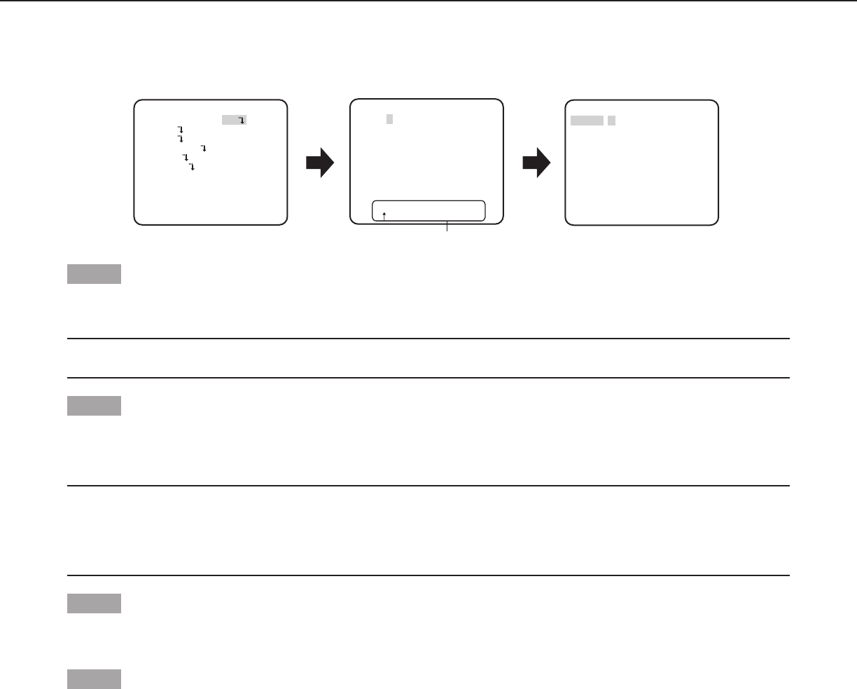
Basic operation
The operations in the setup menu are performed with the operation buttons after calling up the setup menu on the connected video
monitor.
The description below explains how to operate the setup menu basically.
Screenshots of WV-CF314LE are shown as an example.
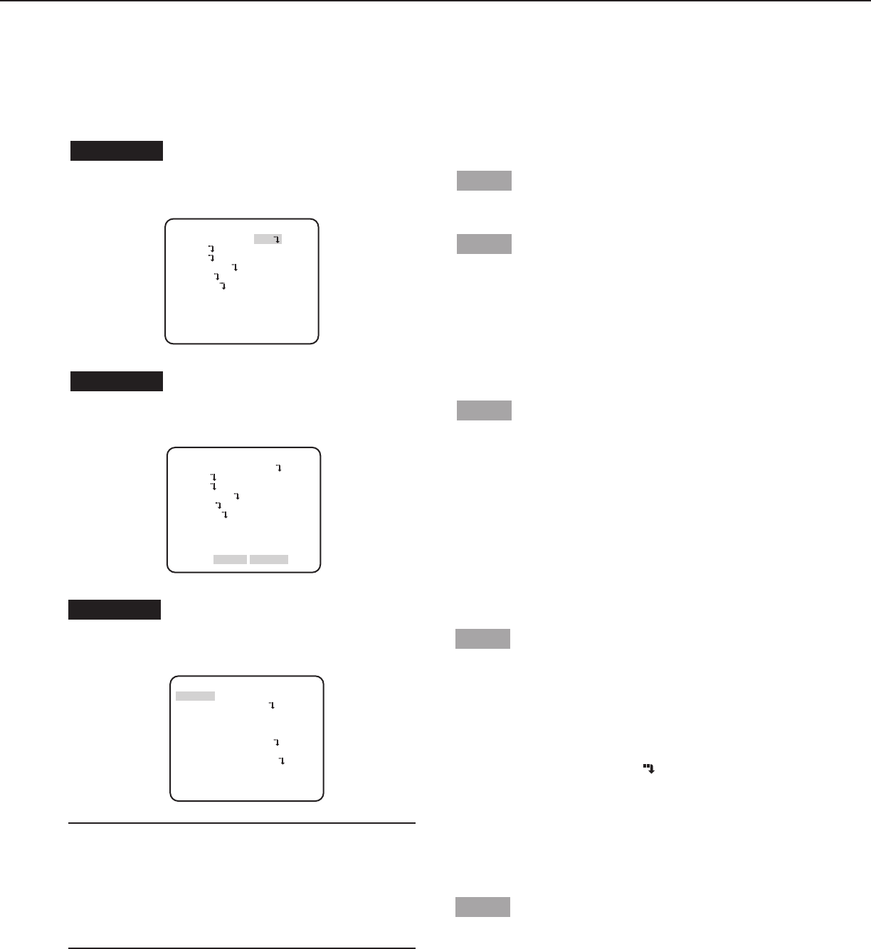
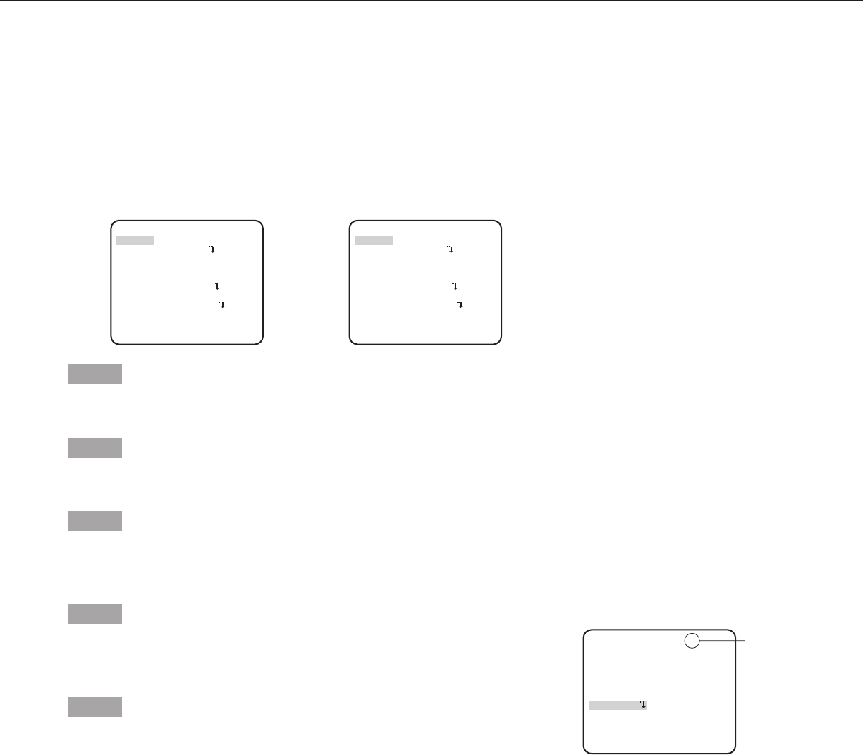
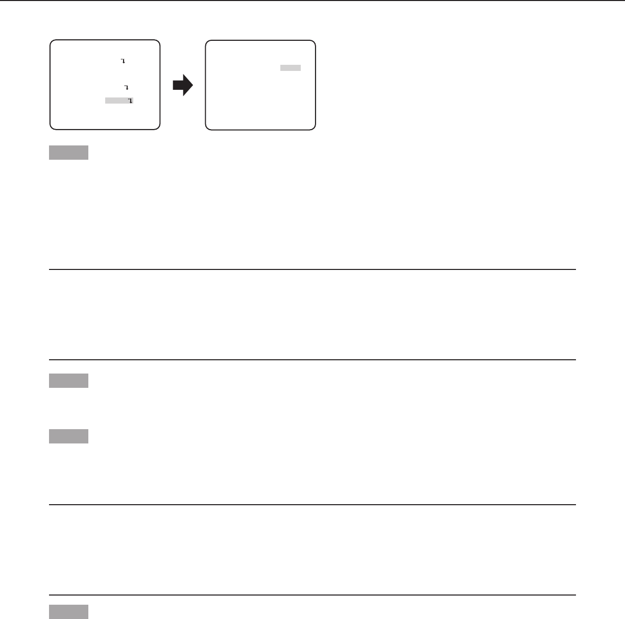
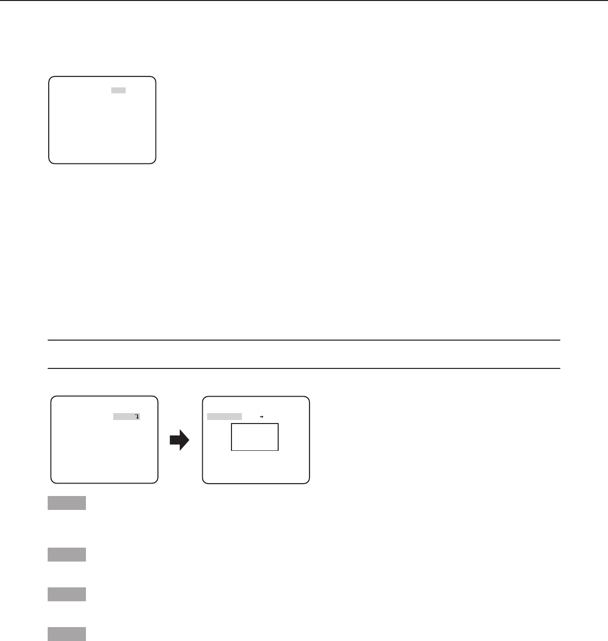
Screenshot 2
The setup mode changes to “ENABLE”, and the setup menu
becomes ready to be set. Step 3
Move the cursor to the item to be set, and press the [SET]
button.
Screenshot 1
Hold down the [SET] button for about 2 seconds to call up the
top screen of the setup menu. Step 1
Press the [UP] or [DOWN] button to move the cursor to “END”.
Step 2
Press the [RIGHT] button to move the cursor to “SETUP”,
and press the [SET] button to change the setup mode from
“DISABLE” to “ENABLE”.
MODEL WV-CF314L
CAMERA ID OFF
CAMERA
SYSTEM
BACK-FOCUS
END SETUP DISABIE
SPECIAL
LANGUAGE
MODEL WV-CF314L
CAMERA ID OFF
CAMERA
SYSTEM
BACK-FOCUS
END SETUP ENABLE
SPECIAL
LANGUAGE
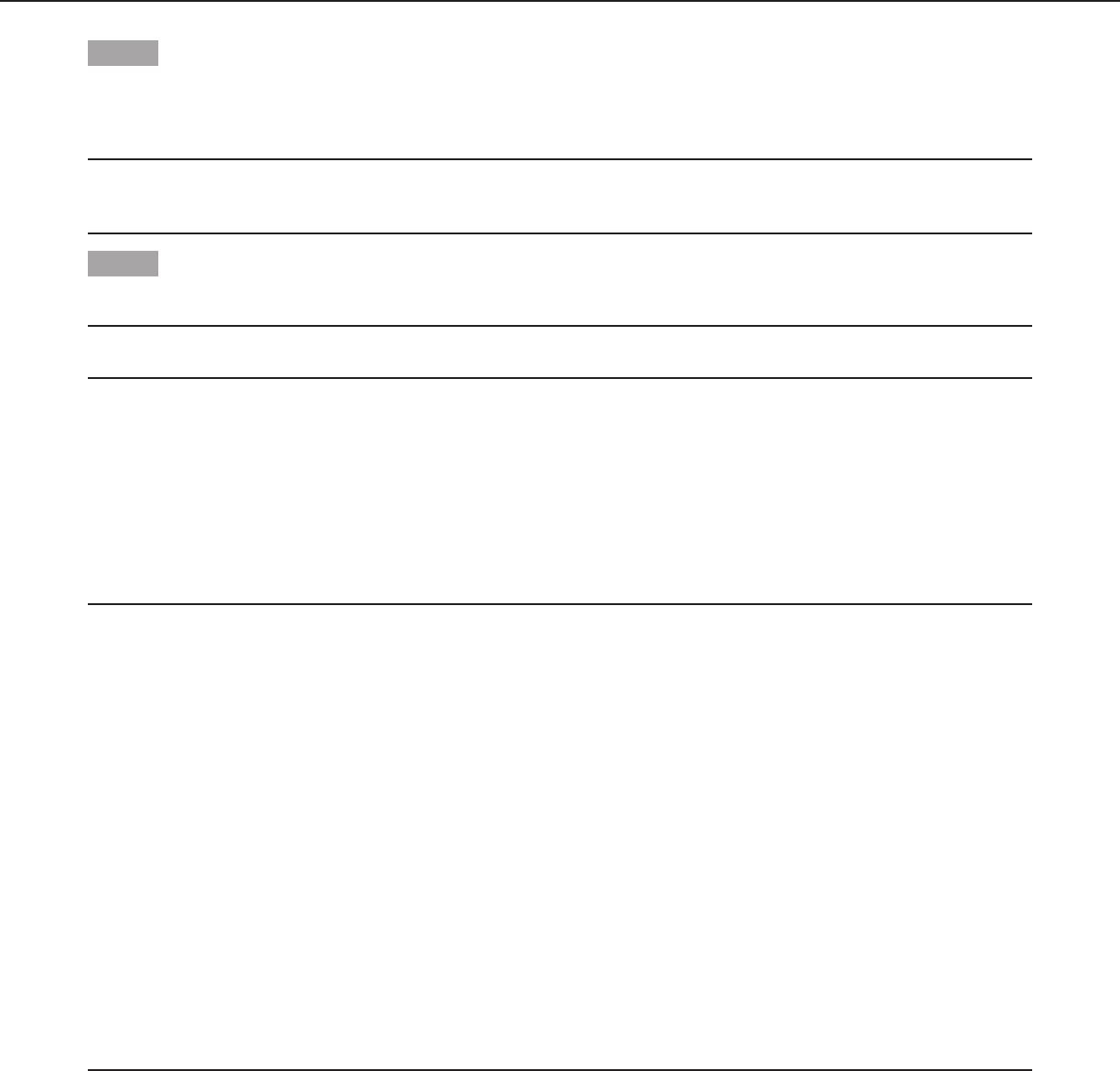
Screenshot 3
The selected setup screen in the setup menu appears on the
screen.
Note:
• Ifthetopscreenofthesetupmenuiscalledupwiththe
operation buttons, the setup mode is always “DISABLE” to
prevent operation errors.
To perform settings in the setup menu, change the setup
mode to “ENABLE”.
• Thecursorisareverselyhighlightedpart.
Step 4
Perform the settings for each item.
• Selectionofsettingitem:
Press the [UP] or [DOWN] button to move the cursor.
• Changeofsettings:
Press the [RIGHT] or [LEFT] button.
• Displayofadvancedsetupscreen:
Press the [SET] button when “ ” is attached to the target
setting item.
• Returntoprevioussetupscreen:
Move the cursor to “RET” and press the [SET] button.
• Returntothetopscreen:
Move the cursor to “TOP” and press the [SET] button, to
display the top screen of the setup menu.
Step 5
Move the cursor to “END” and press the [SET] button to return
to the camera image screen, or wait about 5 minutes and the
setup menu will automatically close.
**CAMERA SETUP**
SCENE1
ALC/ELC ALC
SHUTTER OFF
AGC ON(LOW)
SENS UP OFF
WHITE BAL ATW1
DNR HIGH
AUTO2
VMD
RET TOP END
D&N(IR)
OFF
6
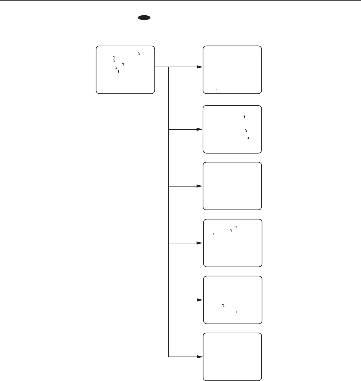
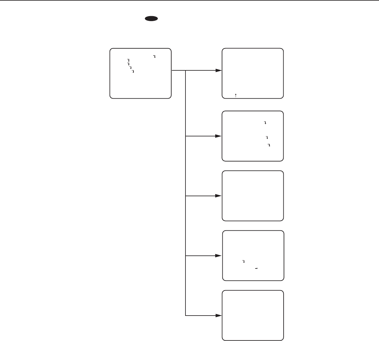
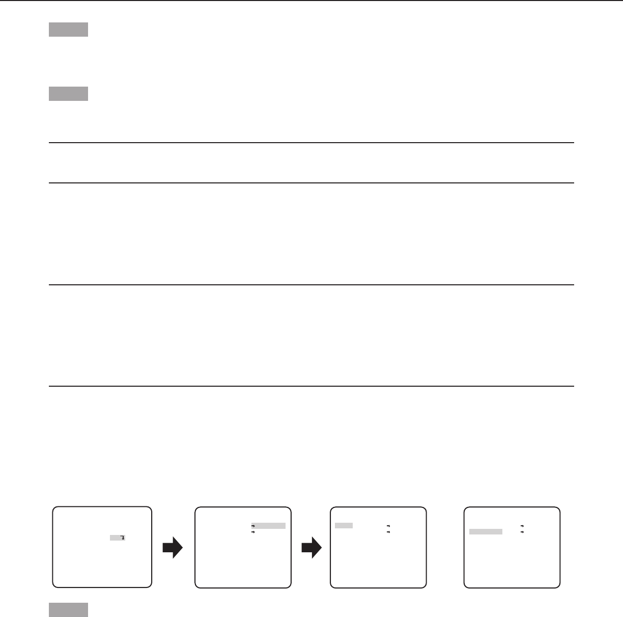
Screen transition diagram
CW324L
CW314L
CW304L
CF314L
CF304L
Top screen
MODEL WV-CW324L
CAMERA ID OFF
CAMERA
SYSTEM
BACK-FOCUS
END SETUP DISABLE
SPECIAL
LANGUAGE
“LANGUAGE SETUP” screen
**LANGUAGE SETUP**
LANGUAGE ENGLISH
SET
RET TOP END
“CAMERA ID” screen
**CAMERA ID**
0123456789
ABCDEFGHIJKLM
NOPQRSTUVWXYZ
().,'":;&#!?=
+-*/%$
SPACE POSI
RET TOP END RESET
................
“CAMERA SETUP” screen
**CAMERA SETUP**
SCENE1
ALC/ELC ALC
SHUTTER OFF
AGC ON(LOW)
SENS UP OFF
WHITE BAL ATW1
DNR HIGH
AUTO2
VMD
RET TOP END
D&N(IR)
OFF
“SPECIAL SETUP” screen
**SPECIAL SETUP**
CHROMA GAIN ....I..160
AP GAIN ..I.... 32
PEDESTAL .I..... 16
- +
PIX OFF
CAMERA RESET
PUSH SET
SER.NO. XXXXXXXX
RET TOP END
“BACK FOCUS” screen
**BACK-FOCUS SETUP**
ABF
MANUAL-ADJ
C/L B/W FIX
PUSH SET
RET TOP END
“SYSTEM SETUP” screen
SYNC INT
**SYSTEM SETUP**
PRIVACY ZONE OFF
STABILIZER OFF
EL-ZOOM OFF
UPSIDE-DOWN OFF
- +
LDC I...... 0
RET TOP END
7
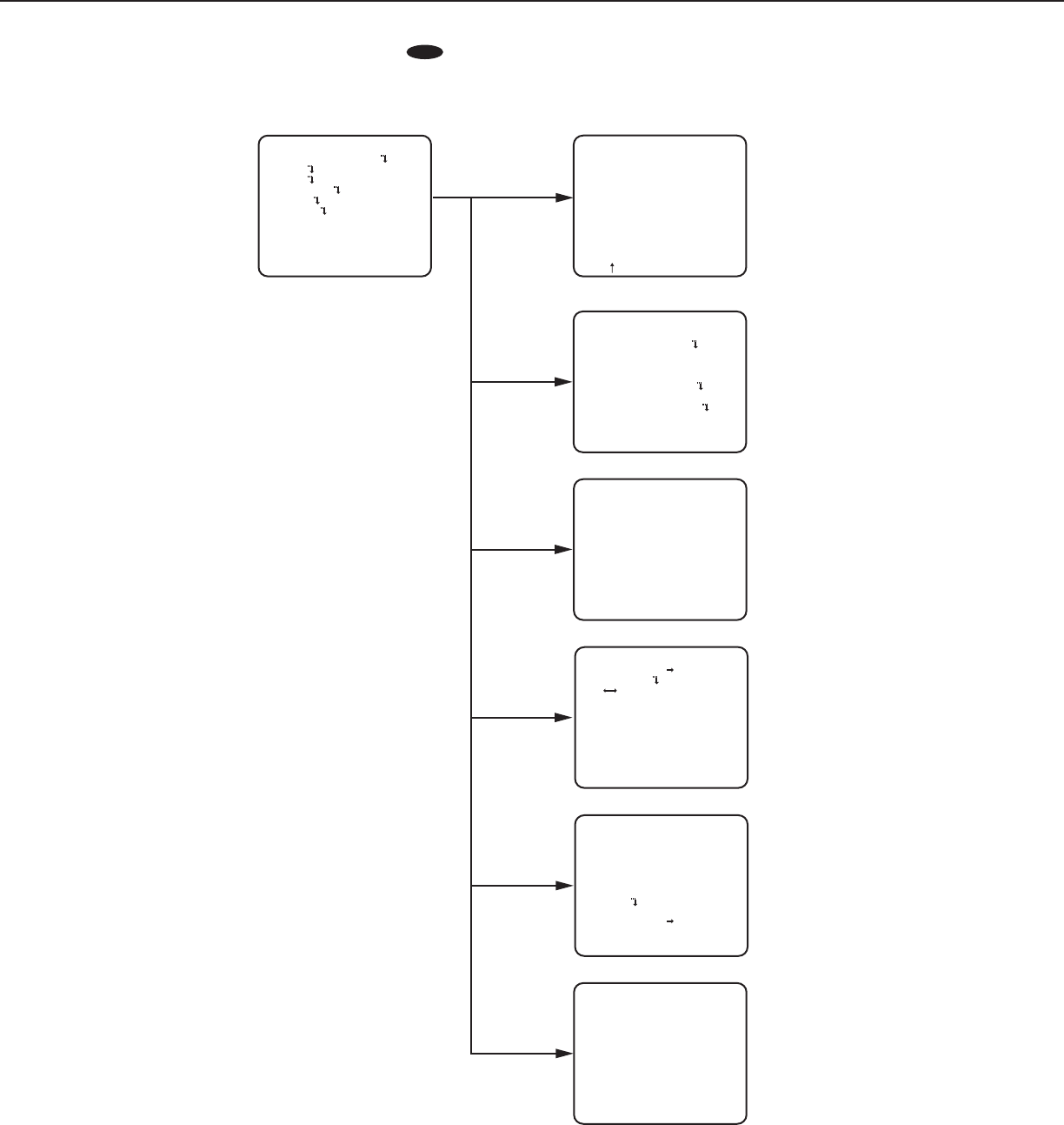
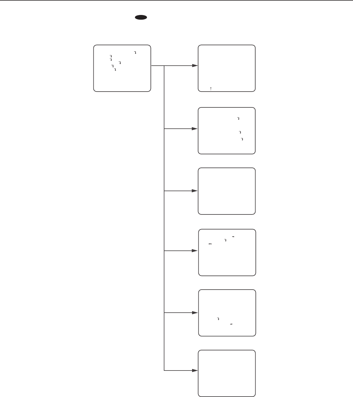
Screen transition diagram
CW324L
CW314L
CW304L
CF314L
CF304L
Top screen
MODEL WV-CW314L
CAMERA ID OFF
CAMERA
SYSTEM
BACK-FOCUS
END SETUP DISABLE
SPECIAL
LANGUAGE
“LANGUAGE SETUP” screen
**LANGUAGE SETUP**
LANGUAGE ENGLISH
SET
RET TOP END
“CAMERA ID” screen
**CAMERA ID**
0123456789
ABCDEFGHIJKLM
NOPQRSTUVWXYZ
().,'":;&#!?=
+-*/%$
SPACE POSI
RET TOP END RESET
................
“CAMERA SETUP” screen
**CAMERA SETUP**
SCENE1
ALC/ELC ALC
SHUTTER OFF
AGC ON(LOW)
SENS UP OFF
WHITE BAL ATW1
DNR HIGH
AUTO2
VMD
RET TOP END
D&N(IR)
OFF
“SPECIAL SETUP” screen
**SPECIAL SETUP**
CHROMA GAIN ....I..160
AP GAIN ..I.... 32
PEDESTAL .I..... 16
- +
PIX OFF
CAMERA RESET
PUSH SET
SER.NO. XXXXXXXX
RET TOP END
“SYSTEM SETUP” screen
SYNC INT
**SYSTEM SETUP**
PRIVACY ZONE OFF
STABILIZER OFF
EL-ZOOM OFF
UPSIDE-DOWN OFF
- +
LDC I...... 0
RET TOP END
“BACK FOCUS” screen
**BACK-FOCUS SETUP**
ABF
MANUAL-ADJ
C/L B/W FIX
PUSH SET
RET TOP END
8
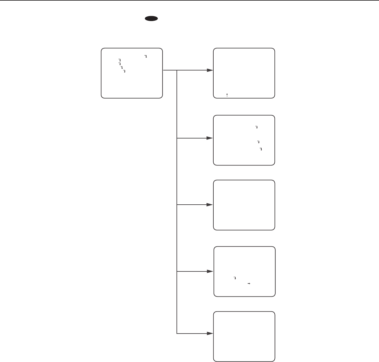
Screen transition diagram
CW324L
CW314L
CW304L
CF314L
CF304L
Top screen
MODEL WV-CW304L
CAMERA ID OFF
CAMERA
SYSTEM
END SETUP DISABLE
SPECIAL
LANGUAGE
“LANGUAGE SETUP” screen
**LANGUAGE SETUP**
LANGUAGE ENGLISH
SET
RET TOP END
“CAMERA ID” screen
**CAMERA ID**
0123456789
ABCDEFGHIJKLM
NOPQRSTUVWXYZ
().,'":;&#!?=
+-*/%$
SPACE POSI
RET TOP END RESET
................
“CAMERA SETUP” screen
**CAMERA SETUP**
SCENE1
ALC/ELC ELC
SHUTTER ---
AGC ON(LOW)
SENS UP OFF
WHITE BAL ATW1
DNR HIGH
AUTO2
VMD
RET TOP END
D&N(IR)
OFF
“SPECIAL SETUP” screen
**SPECIAL SETUP**
CHROMA GAIN ....I..160
AP GAIN ..I.... 32
PEDESTAL .I..... 16
- +
PIX OFF
CAMERA RESET
PUSH SET
SER.NO. XXXXXXXX
RET TOP END
“SYSTEM SETUP” screen
SYNC INT
**SYSTEM SETUP**
PRIVACY ZONE OFF
STABILIZER OFF
EL-ZOOM OFF
UPSIDE-DOWN OFF
- +
LDC ····I··160
RET TOP END
9
Screen transition diagram
CW324L
CW314L
CW304L
CF314L
CF304L
neercs ”DI AREMAC“neercs poT
“CAMERA SETUP” screen
“SYSTEM SETUP” screen
“BACK-FOCUS SETUP” screen
MODEL WV-CF314L
CAMERA ID OFF
CAMERA
SYSTEM
SPECIAL
LANGUAGE
END SETUP DISABLE
**CAMERA ID**
0123456789
ABCDEFGHIJKLM
NOPQRSTUVWXYZ
().,'":;&#!?=
+-*/%$
SPACE POSI
RET TOP END RESET
................
**SYSTEM SETUP**
PRIVACY ZONE OFF
SYNC INT
STABILIZER OFF
EL-ZOOM OFF
UPSIDE-DOWN OFF
- +
LDC I...... 0
RET TOP END
**BACK-FOCUS SETUP**
ABF PUSH SET
MANUAL-ADJ
C/L B/W FIX
RET TOP END
“SPECIAL SETUP” screen
“LANGUAGE SETUP” screen
**LANGUAGE SETUP**
LANGUAGE ENGLISH
SET
RET TOP END
**SPECIAL SETUP**
CHROMA GAIN ....I..160
AP GAIN ...I.... 32
PEDESTAL . ..
I... 16
- +
PIX OFF
CAMERA RESET PUSH SET
SER.NO. XXXXXXXX
RET TOP END
**CAMERA SETUP**
SCENE1
ALC/ELC ALC
SHUTTER OFF
AGC ON(LOW)
SENS UP OFF
WHITE BAL ATW1
DNR HIGH
AUTO2
VMD
RET TOP END
D&N(IR)
OFF
BACK-FOCUS
10
Screen transition diagram
CW324L
CW314L
CW304L
CF314L
CF304L
neercs ”DI AREMAC“neercs poT
“CAMERA SETUP” screen
“SYSTEM SETUP” screen
MODEL WV-CF304L
CAMERA ID OFF
CAMERA
SYSTEM
END SETUP DISABLE
SPECIAL
LANGUAGE
**CAMERA ID**
0123456789
ABCDEFGHIJKLM
NOPQRSTUVWXYZ
().,'":;&#!?=
+-*/%$
SPACE POSI
RET TOP END RESET
................
**SYSTEM SETUP**
SYNC INT
PRIVACY ZONE OFF
STABILIZER OFF
EL-ZOOM OFF
UPSIDE-DOWN OFF
LDC ····I··160
RET TOP END
“SPECIAL SETUP” screen
“LANGUAGE SETUP” screen
**LANGUAGE SETUP**
LANGUAGE ENGLISH
SET
RET TOP END
**SPECIAL SETUP**
CHROMA GAIN ....I..160
AP GAIN ...I.... 32
PEDESTAL . ..
I... 16
- +
PIX OFF
CAMERA RESET PUSH SET
SER.NO. XXXXXXXX
RET TOP END
**CAMERA SETUP**
SCENE1
ALC/ELC ELC
SHUTTER ---
AGC ON(LOW)
SENS UP OFF
WHITE BAL ATW1
DNR HIGH
AUTO2
VMD
RET TOP END
D&N(IR)
OFF
- +
11
Camera title setting [CAMERA ID]
This item specified the camera title. The camera title that indicates the camera location and other information about the camera is
created with alphanumerics and symbols, and is displayed on the screen. The camera title is named with up to 16 characters.
Follow the procedure below to specify the camera title.
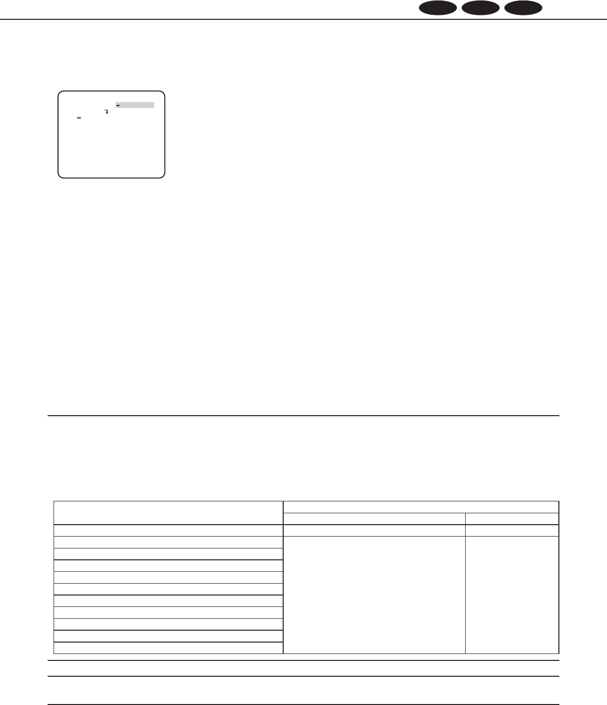
Step 1
Select “ON” for “CAMERA ID”, and then press the [SET] button.
→ The “CAMERA ID” screen appears.
Important:
• When“CAMERAID” is set to “OFF”, the camera title does not appear even after setting the camera title.
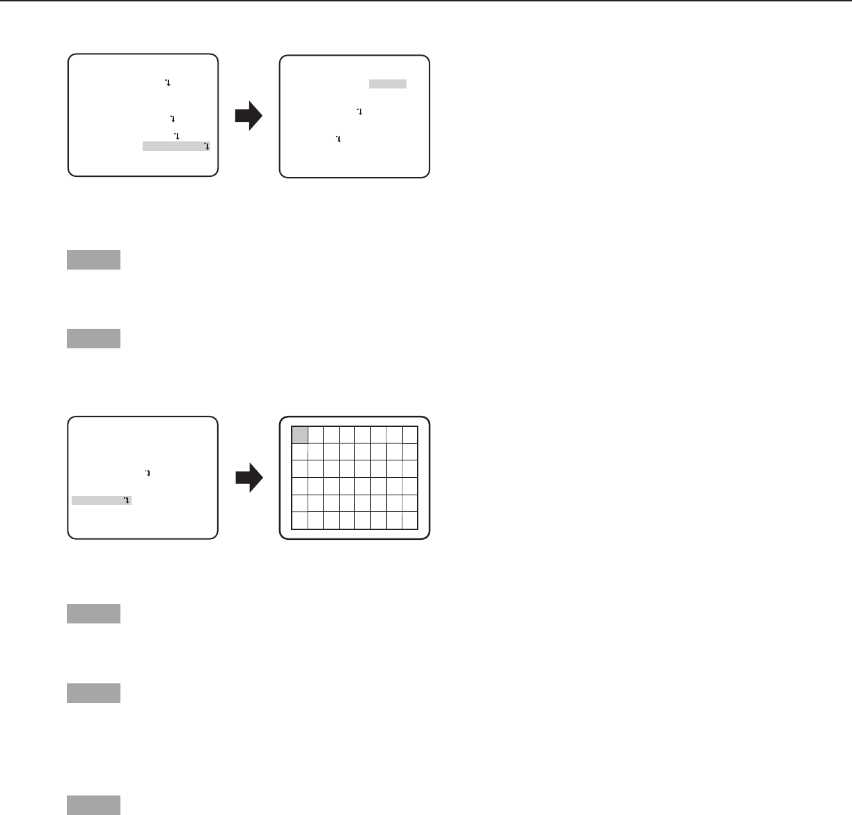
Step 2
Move the cursor to the target item with use of the [UP], [DOWN], [RIGHT], and [LEFT] buttons, and press the [SET] button to enter
the character.
→ The entered characters are displayed in the editing area.
<Characterentry>
• Toreviseacharacter,movethearrow(↑) in the editing area to a wrong character with use of the [RIGHT] or [LEFT] button, and
enter a correct character.
• Toenterablank,movethecursorto“SPACE” and press the [SET] button.
• Todeletealltheenteredcharacters,movethecursorto“RESET” and press the [SET] button.
Step 3
Move the cursor to “POSI” and press the [SET] button after title entered.
→ The display positioning screen appears.
Step 4
Press the [UP], [DOWN], [RIGHT], and [LEFT] buttons to decide the title position and press the [SET] button.
→ The title position is specified.
FLOOR 1
Editing area
Top screen “CAMERA ID” screen Display positioning screen
MODEL WV-CF314L
CAMERA ID ON
CAMERA
SYSTEM
BACK-FOCUS
END SETUP ENABLE
SPECIAL
LANGUAGE
**CAMERA ID**
0123456789
ABCDEFGHIJKLM
NOPQRSTUVWXYZ
().,'":;&#!?=
+-*/%$
SPACE POSI
RET TOP END RESET
................
12
Screen when “SCENE1” is selected Screen when “SCENE2” is selected
**CAMERA SETUP**
SCENE1
ALC/ELC ALC
SHUTTER OFF
AGC ON(LOW)
SENS UP OFF
WHITE BAL ATW1
DNR HIGH
AUTO2
VMD OFF
RET TOP END
D&N(IR)
**CAMERA SETUP**
SCENE2
COPY(SCENE1)
ALC/ELC ALC
SHUTTER OFF
AGC ON(LOW)
SENS UP OFF
WHITE BAL ATW1
DNR HIGH
AUTO2
VMD OFF
RET TOP END
D&N(IR)
Camera operation setting [CAMERA SETUP]
The following describes the camera operation settings. The following settings can be configured on the “CAMERA SETUP” screen
displayed from the top screen.
Refer to page 5 for how to call up the screen.
The settings configured on the “CAMERA SETUP” screen will be saved as a scene file.
1. Register a scene le [SCENE1/SCENE2]
It is possible to register 2 patterns of scene file. When different settings are to be applied between day and night, SCENE1 can be
applied in the daytime and SCENE2 at night. Change between the scene files can be made by shortcut operation. ( page 28)
“SCENE1” is set as the default setting.
Step 1
After confirming that “SCENE1” is selected, configure the settings of “ALC/ELC” through “VMD”. ( page 12-20)
To change the scene files, go to step 2.
Step 2
Move the cursor to “SCENE1” and press the [RIGHT] or [LEFT] button to select “SCENE2”.
→ The screen changes and displays “SCENE2”.
Step 3
To configure the settings of “SCENE2” using the settings of “SCENE1”, press the [SET] button after moving the cursor to
“COPY(SCENE1)”.
→ The settings of “SCENE1” will be copied to “SCENE2”.
Step 4
Edit the settings to be changed as the settings of “SCENE2”.
The number displayed at the right side of the title on each setting screen indicates a scene
file number.
Step 5
Move the cursor to “SCENE2” and press the [RIGHT] or [LEFT] button to select “SCENE1”
to resume normal operation.
2. Light quantity control method selection [ALC/ELC]
The method of controlling the quantity of light is selected from the following in accordance with the lens to be used.
ALC (default): The iris of the lens is automatically adjusted in accordance with the brightness of a subject. Select “ALC” when using
an ALC lens.
ALC+: Controls the quantity of light with a combination of the electronic shutter and auto iris. This selection is suitable at shooting
a bright subject such as an outdoor subject with auto iris lens. Be aware that flicker may occur when a subject is under
fluorescent lighting.
ELC: Controls the quantity of light with the electronic shutter. This selection is suitable for use of a lens with fixed iris or manual iris.
Scene file
number
**ALC CONT**(1)
- +
.I..... 0
“ALC CONT” screen
BACK LIGHT COMP
BLC OFF
ABS OFF
LEVEL
RET TOP END
MASK SET
13
Follow the procedure below.
“ALC CONT” screen Mask setting screen“CAMERA SETUP” screen
**ALC CONT**(1)
BACK LIGHT COMP
OFF
MASK SET
- +
LEVEL .I..... 0
RET TOP END
BLC
OFF
ABS
**CAMERA SETUP**
SCENE1
ALC/ELC ALC
SHUTTER OFF
AGC ON(LOW)
SENS UP OFF
WHITE BAL ATW1
DNR HIGH
AUTO2
VMD OFF
RET TOP END
D&N(IR)
Step 1
Set “ALC/ELC” to “ALC”, and press the [SET] button.
→The “ALC CONT” screen appears.
Note:
•
CW324L
CW314L
CW304L
CF314L
CF304L
CW324L
CW314L
CW304L
CF314L
CF304L
CW324L
CW314L
CW304L
CF314L
CF304L
When “ALC/ELC” is set to “ELC” or “ALC+” and the [SET] button is pressed, the “ELC CONT” or “ALC+ CONT”
screen will appear.
•
CW324L
CW314L
CW304L
CF314L
CF304L
CW324L
CW314L
CW304L
CF314L
CF304L
Only have “ELC” function.
Step 2
Move the cursor to “BLC” and select the “ON” or “OFF”.
ON: Activates the BLC function.
OFF (default): Deactivates the BLC function.
Step 3
Move the cursor to “ABS” and select from the following options.
ABS (Auto Black Stretch Technology)
The latest digital signal technology is applied to automatically detect the dark areas in the image, acquire the brightness data around
the dark areas, and perform real-time color adjustment by calculating the best correction curve for each area. This function can be
used to perform real-time adjustment and correction of back light and dark area, and reproduce natural, clear images.
ON: Uses ABS.
OFF (default): Does not use ABS.
Step 4
When “BLC” is set to “OFF”, bright areas of an image are masked to facilitate the visibility of dark areas.
Move the cursor to “MASK SET” and press the [SET] button.
→The mask setting screen appears.
“ALC CONT” screen
**ALC CONT**(1)
BACK LIGHT COMP
OFF
ABS
MASK SET
- +
LEVEL .I..... 0
RET TOP END
BLC
OFF
Mask setting screen

14
Step 5
Press the [UP], [DOWN], [RIGHT], and [LEFT] buttons to move the flashing cursor to the area to be masked and press the [SET]
button.
When the selected area is masked, the masked area will start blinking (between stripes and white). When the flashing cursor is moved
to other areas, the masked area will be displayed in white.
Repeat the above procedure to mask other areas as necessary.
Note:
• Tocancelthemasking,selectthemaskedareatobecanceled,andthenpressthe[SET]button.Themaskedareawillbedeleted.
Step 6
Hold down the [SET] button for more than 2 seconds after completion of masking.
→ Return to the previous menu.
Step 7
Move the cursor to “LEVEL” and press the [RIGHT] or [LEFT] button to adjust the level.
3. Electronic shutter setting [SHUTTER]
The variation in shutter speed allows users to perform the following.
Increased shutter speed prevents blurring fast-moving subjects.
The shutter speed is selectable from the following.
OFF (1/50) (default), 1/120, 1/250, 1/500, 1/1000, 1/2000, 1/4000, 1/10000, 1/120000
Note:
• When“ALC/ELC”issetto“ELC”or“ALC+”,“---”appearsandtheshutterfunctioncannotbeactivated.
•
CW324L
CW314L
CW304L
CF314L
CF304L
CW324L
CW314L
CW304L
CF314L
CF304L
Control the quantity of light with ELC, “---” appears and the shutter function cannot be activated.
4. Gain control setting [AGC]
Select a gain control setting from the following.
ON (HIGH)/ON (MID)/ON (LOW) (default): Automatically increases the gain to make the screen brighter when the illuminance of the
subject becomes darker.
HIGH, MID and LOW indicate the gain level.
OFF: Does not increase the gain.
Note:
• When“SENSUP”issettotheAUTOmode,“AGC”cannotbesetto“OFF”.
5. Electronic sensitivity enhancement setting [SENS UP]
Use of the electronic sensitivity enhancement function increases the light sensitivity of the CCD, and accordingly the image becomes
brighter. The magnification is unchanged for selection of FIX, and the magnification is automatically adjusted in accordance with the
illuminance of a photographic subject for selection of AUTO.
The magnification of the electronic sensitivity is selectable from the following.
CW324L
CW314L
CW304L
CF314L
CF304L
CW324L
CW314L
CW304L
CF314L
CF304L
CW324L
CW314L
CW304L
CF314L
CF304L
OFF (default)/X2 AUTO/X4 AUTO/X6 AUTO/X10 AUTO/X16 AUTO/X32 AUTO/OFF/X2 FIX/X4 FIX/X6 FIX/
X10 FIX/X16 FIX/X32 FIX/X64 FIX/X128 FIX/X256 FIX/X512 FIX
CW324L
CW314L
CW304L
CF314L
CF304L
CW324L
CW314L
CW304L
CF314L
CF304L
OFF (default)/X2 AUTO/X4 AUTO/X6 AUTO/X10 AUTO/X16 AUTO/X32 AUTO
15
Note:
•
CW324L
CW314L
CW304L
CF314L
CF304L
CW324L
CW314L
CW304L
CF314L
CF304L
CW324L
CW314L
CW304L
CF314L
CF304L
When “ALC/ELC” is set to “ELC” or “ALC+”, only the AUTO mode is enabled.
•
CW324L
CW314L
CW304L
CF314L
CF304L
CW324L
CW314L
CW304L
CF314L
CF304L
CW324L
CW314L
CW304L
CF314L
CF304L
When “SHUTTER” is set to options other than “OFF”, the electronic sensitivity enhancement setting cannot be
performed and “---” appears.
• Whenthemagnificationof “SENSUP”is increased,the screenbecomes coarser,morewhitish,or moreflawed. However,this
phenomenon is normal.
6. White balance setting [WHITE BAL]
The white balance adjustment is selectable from the following.
ATW1 (default): Activates the automatic color temperature tracking mode.
The camera continuously check the color temperature of the light source and automatically adjusts the white
balance. The adjustment of the color temperature ranges from approx. 2700 K to 6000 K.
ATW2: Activates the sodium lamp automatic color temperature tracking mode. The camera automatically achieves an optimal white
balance under the sodium lamp. The adjustment of the color temperature ranges from approx. 2000 K to 6000 K.
AWC: Activates the automatic white balance control mode. This adjustment is suitable for a location where a light source is stable.
The adjustment of the color temperature ranges from 2000 K to 10000 K. When “AWC” is selected, the white balance needs
to be adjusted.
Note:
• Ifthesituationmeetsoneofthefollowings,colormaynotbeaccuratelyreproduced.
• Thesubjectismostlyhighly-colored.
• Thephotographicsceneisunderthebrightblueskyoratnightfall.
• Theilluminationofthelightilluminatingthesubjectisinsufficient.
When “AWC” is selected, follow the steps below to adjust the white balance.
“CAMERA SETUP” screen
**CAMERA SETUP**
SCENE1
ALC/ELC ALC
SHUTTER OFF
AGC ON(LOW)
SENS UP OFF
WHITE BAL AWC PUSH SET
DNR HIGH
AUTO2
VMD OFF
RET TOP END
D&N(IR)
Step 1
Set “WHITE BAL” to “AWC” and press the [LEFT] button to change to “AWC → PUSH SET”.
Step 2
Press the [SET] button and adjust the white balance. “AWC → PUSH SET” is reversely highlighted during adjustment. When the
reversely highlighted display is restored, the white balance adjustment is completed.
Step 3
Press the [RIGHT] button to select “AWC”. Refer to this page for fine adjustment of the white balance.
Note:
• Theadjustmentofthecolortemperaturerangesfromapprox.2000Kto10000K.Iftherangeisoutofthisadjustmentrangeor
lighting directed to a subject is too dark, the white balance may not be adjusted. In such a case, “AWC → PUSH SET” stays
reversely highlighted.
16
Manual ne adjustment of white balance
The white balance is manually fine adjusted after white balance automatically adjustment in the automatic color temperature tracking
mode (ATW1, ATW2) or automatic white balance control mode (AWC).
Follow the procedures below.
**ATW1**(1)
R
- +
B
- +
AREA
RET TOP END
**ATW1 AREA**(1)
POSITION PUSH SET
RET TOP END
Area setting screen
RESET
...I... 0
...I... 0
“CAMERA SETUP” screen Fine adjustment screen
**CAMERA SETUP**
SCENE1
ALC/ELC ALC
SHUTTER OFF
AGC ON(LOW)
SENS UP OFF
WHITE BAL ATW1
DNR HIGH
AUTO2
VMD OFF
RET TOP END
D&N(IR)
Step 1
Set “WHITE BAL” to “ATW1”, “ATW2” or “AWC” and press the [SET] button.
→ The fine adjustment screen appears.
Step 2
Move the cursor to “R” and “B” and press the [LEFT] or [RIGHT] button to fine adjust the level for each. “R” stands for red and “B”
stands for blue.
When the level indicator moves in the “+” direction, the color becomes deeper, and when the level indicator moves in the “–” direction,
the color becomes lighter.
Step 3
Move the cursor to “AREA” and press the [SET] button to enter “AREA” setting screen.
The area to detect white area of white balance can be set on the area setting screen. The area to detect white area of white balance
is displayed full-screen by default.
Step 4
Move the cursor to “POSITION” and press the [SET] button.
Step 5
Press the [UP], [DOWN], [RIGHT] and [LEFT] buttons to move to the upper-left part of the area to be set, and press the [SET] button.
Step 6
Press the [UP], [DOWN], [RIGHT] and [LEFT] buttons to move to the lower-right part of the area to be set, and press the [SET] button.
7. Digital noise reduction function setting [DNR]
The digital noise reduction function reduces noise automatically under the condition of low illuminance.
The effect level of the noise reduction function is selectable from the following.
LOW: Low level of noise reduction (small residual image)
HIGH (default): High level of noise reduction (large residual image)
8. Black-and-white mode setting [D&N (IR) ]
The settings relating to the black-and-white mode can be configured.
Follow the procedure below.
17
AUTO2
**D&N(IR) **(1)
LEVELHIGH
DURATION TIME
IR LED LIGHT FIX
S L
BURST(BW)ON
RET TOP END
.I..
“CAMERA SETUP” screen “D&N (IR)” screen
**CAMERA SETUP**
SCENE1
ALC/ELC ALC
SHUTTER OFF
AGC ON(LOW)
SENS UP OFF
WHITE BAL ATW1
DNR HIGH
AUTO2
VMD OFF
RET TOP END
D&N(IR)
Step 1
Move the cursor to “D&N (IR)” and select the mode from the following.
AUTO1: Automatically switches between color and black-and-white images in accordance with the illuminance. The black-and-white
mode is selected for dark images, and the color mode is selected for bright images.
AUTO2 (default): Automatically switches between color and black-and-white images in accordance with the illuminance. The black-
and-white mode is selected for dark images, and the color mode is selected for bright images. Opening or closing
IR LED lights can be chosen in this mode.
ON: Displays black-and-white images. Opening or closing IR LED lights can be chosen in this mode.
OFF: Displays color images.
Note:
• When“AUTO1”or“AUTO2”isselected,itisrecommendedtoset“AGC”to“ON”.
• If a subject is always moving or the screen is occupied with a uniform color, brightness determination may not be performed
successfully because the brightness is merely determined by information from the CCD image sensor. When “AUTO2” is
selected, the wave length of the light source shall be 800 nm or longer.
• When“AUTO1”isselected,toobtaincolorimages,asufficientlevelofilluminance(approx.30lxormore)isrequired.
• When“AUTO2”isselected,toobtaincolorimages,asufficientlevelofilluminance(approx.40lxormore)isrequired.
Step 2
Press the [SET] button.
→ The “D&N (IR)” screen appears.
Step 3
Move the cursor to “LEVEL” and select a brightness level at which switching between color and black-and-white images is performed
from the following.
LOW: Switches from color to black-and-white images when the ambient illuminance of the camera is less than 1 lx.
HIGH (default): Switches from color to black-and-white images when the ambient illuminance of the camera is less than 2 lx.
Note:
• Whenthe“D&N(IR)”issetto“AUTO2”and“AGC”issetto“ON(LOW)”,theswitchingilluminancedescribedabovecanbesatisfied.
• Theswitchingilluminancelevelvarieswithsubjects,lightsources,andlenses.
• TheswitchingilluminancelevelvariesinaccordancewithAGCsetting.( page 14)
• Theswitchingilluminancesdescribedabovearereferencevalues.Theswitchingilluminanceshallbedecidedbasedontheactual
installation environment.
• Theremayberepeatedswitchingbetweencolorandblack-and-whiteimagesdependingonthesettingandenvironment.
Step 4
Move the cursor to “DURATION TIME” and select a time for switching between color and black-and-white images from the following.
2 seconds - 10 seconds (default) - 30 seconds - 60 seconds
(S) (L)
18
Step 5
Move the cursor to “BURST (BW)”, and decide whether or not to provide a burst signal output in the black-and-white mode.
ON (default): Provides a burst signal output.
OFF: Does not provide any burst signal output.
Note:
• Images may not be displayed appropriately without burst signals when camera images are displayed in the black-and-white
mode depending on a monitor or VTR model to be used. In such a case, set the burst signal output to “ON”.
Step 6
When the “D&N (IR)” is set to “ON” or “AUTO2”, move the cursor to the “IR LED Light”, the mode of IR LED Light can be set.
Note:
• Whenthe“D&N(IR)”issetto“OFF”or“AUTO1”,the“IRLEDLight”willdisplay“---”.
OFF: It can be used as halogen lamp to illuminate.
AUTO: In black-and-white mode, IR LED lights can adjust automatically its brightness depends on the external brightness.
FIX (default): In black-and-white mode, the IR LED lights illuminate, but its brightness keeps unchangeable, which is suit to distant
monitor (more than 6 m).
9. VMD setting [VMD]
The VMD function allows the camera to detect motion and scene change with the camera. Detection of motion or scene change with
the camera can be announced by issuing an alarm signal.
Important:
• Thefollowingcircumstancesmayresultindetectionfailureorfalsedetection.Usethecameraafteradjustingthedetectionarea
and sensitivity.
•Notenoughdifferenceinbrightnessbetweenthebackgroundandthemovingphotographicsubject,orsignificantchangesin
brightness
•Dirtorwaterdropsonthelens
•Insufficientbrightness,forexample,whenshootingatnight
•Thesubjectismovingstraightatthecamera
•Thesubjectismovingtoofastortooslow
•Thesubjectistoosmallortoolarge
•Therearetoomanymovingobjects
•Lightreflectedthroughawindoworfromaroadsurface
•Thecameraisshaking
•Entryofoutsidelight,suchassunlightortheheadlightsofacar
•Flickering fluorescent light
• Subjectchangedetectionmayfailinthefollowingcases.
•Thelensispartiallycoveredorcoveredwithatransparentitem
•Thephotographicsubjectsbeforeandafterchangingthecameradirectionaresimilar
• Falsedetectionmayoccurforapprox.1minuteafterturningonthepower,aftercompletingsettingsintheSETUPmenu,orafter
changing the camera view angle.
• Motiondetectionisthedetectionfunctionwithinthescreenrangeforelectroniczoomof1x.
19
“MOTION DET” screen
**
MOTION DET
**(1)
RET TOP END
LEVEL
2S
OFF
DWELL TIME
DISPLAY MODE
ALARM
MASK SET
....I..
20
-
+
“CAMERA SETUP” screen
MOTION DET
AUTO2
**CAMERA SETUP**
SCENE1
ALC/ELC ALC
SHUTTER OFF
AGC ON(LOW)
SENS UP OFF
WHITE BAL ATW1
DNR HIGH
VMD
RET TOP END
D&N(IR)
Setting of motion detection
Move the cursor to “VMD”, press the [LEFT] or [RIGHT ] button to select “MOTION DET”.
Step 1
Move the cursor to “MOTION DET” and press the [SET] button.
→ The “MOTION DET” screen appears.
Step 2
Move the cursor to “MASK SET” and press the [SET] button.
→ The mask setting screen appears.
“MOTION DET” screen Mask setting screen
**
MOTION DET
**(1)
RET TOP END
LEVEL
2S
OFF
DWELL TIME
DISPLAY MODE
ALARM
MASK SET
....I..
20
-
+
In the masked area, no alarm will be issued even if a moving object is detected. The masked area is set in the same way as the
masked area setting in “Light quantity control method selection”. ( page 13)
Step 3
Hold down the [SET] button for more than 2 seconds after completion of masking.
→ Return to the previous menu.
Step 4
Move the cursor to “ALARM” and press the [LEFT] and [RIGHT] buttons to select “ON” or “OFF”.
ON: Outputs alarm signal when in display mode. Actions may be confirmed through the motion detection mode when a moving
object is detected.
OFF (default): Does not output alarm signal when in display mode.
Step 5
Move the cursor to “DISPLAY MODE” and press the [SET] button.
→ The display mode screen appears.
If a moving object is detected in the set area, the area will be reversely highlighted. Hold down the [SET] button for more than 2
seconds to return.
20
Display mode screen
“MOTION DET” screen
**
MOTION DET
**(1)
RET TOP END
LEVEL
2S
OFF
DWELL TIME
DISPLAY MODE
ALARM
MASK SET
....I..
20
-
+
Step 6
Move the cursor to “LEVEL” and press the [RIGHT] or [LEFT] button to adjust the level.
Repeat step 5 and 6 to adjust to optimal level.
Step 7
Move the cursor to “DWELL TIME ” and select the dwell time from the following. (unit: seconds)
2S (default)/5S /10S /30S
Alarm signal will be issued once a continuously moving object is detected within the specified time.
Setting of scene change detection
This function detects a change in the subject state that occurs by covering the camera with a cloth, a cap, or others, or by changing
the camera direction largely.
Follow the procedure below.
“CAMERA SETUP” screen
VMD SCENE CHANGE
**CAMERA SETUP**
SCENE1
ALC/ELC ALC
SHUTTER OFF
AGC ON(LOW)
SENS UP OFF
WHITE BAL ATW1
DNR HIGH
AUTO2
RET TOP END
D&N(IR)
Step 1
Move the cursor to “VMD” and press the [RIGHT] or [LEFT] button to select “SCENE CHANGE”.
Note:
• The Scene Change function is activated after exit from the menu.
21
Camera system setting [SYSTEM SETUP]
Performs the settings relating to the camera system such as synchronization, alarm input/output terminal and privacy zone. The
following settings can be configured on the “SYSTEM SETUP” screen displayed from the top screen.
Refer to page 5 for how to call up the screen.
10. Synchronization method [SYNC]
Only internal synchronization (INT) can be used.
Multiplexed vertical drive (VD2) synchronization cannot be used.
11. Privacy zone setting [PRIVACY ZONE]
When undesired portions in the camera shooting area (on the screen) exist, those portions (privacy zone) can be set to be hidden. Up
to 8 portions can be specified for the privacy zone.
ON (1): Grays the zone.
ON (2): Mosaics the zone.
OFF (default): Displays the zone normally.
Follow the procedure below to set the privacy zone.
Note:
• Theprivacyzonefunctionisdisabledatinitializingtheunit,i.e.rightafterturningonthepower.
**ZONE NUMBER 1 /8**
PUSH SET
POSITION
UPPER LEFT
RET TOP END
DEL
- +
ZONE LEVEL ..I.... 2
“SYSTEM SETUP” screen “ZONE NUMBER” screen
ON(2)
**SYSTEM SETUP**
SYNC INT
PRIVACY ZONE
STABILIZER OFF
EL-ZOOM OFF
UPSIDE-DOWN OFF
- +
LDC I...... 0
RET TOP END
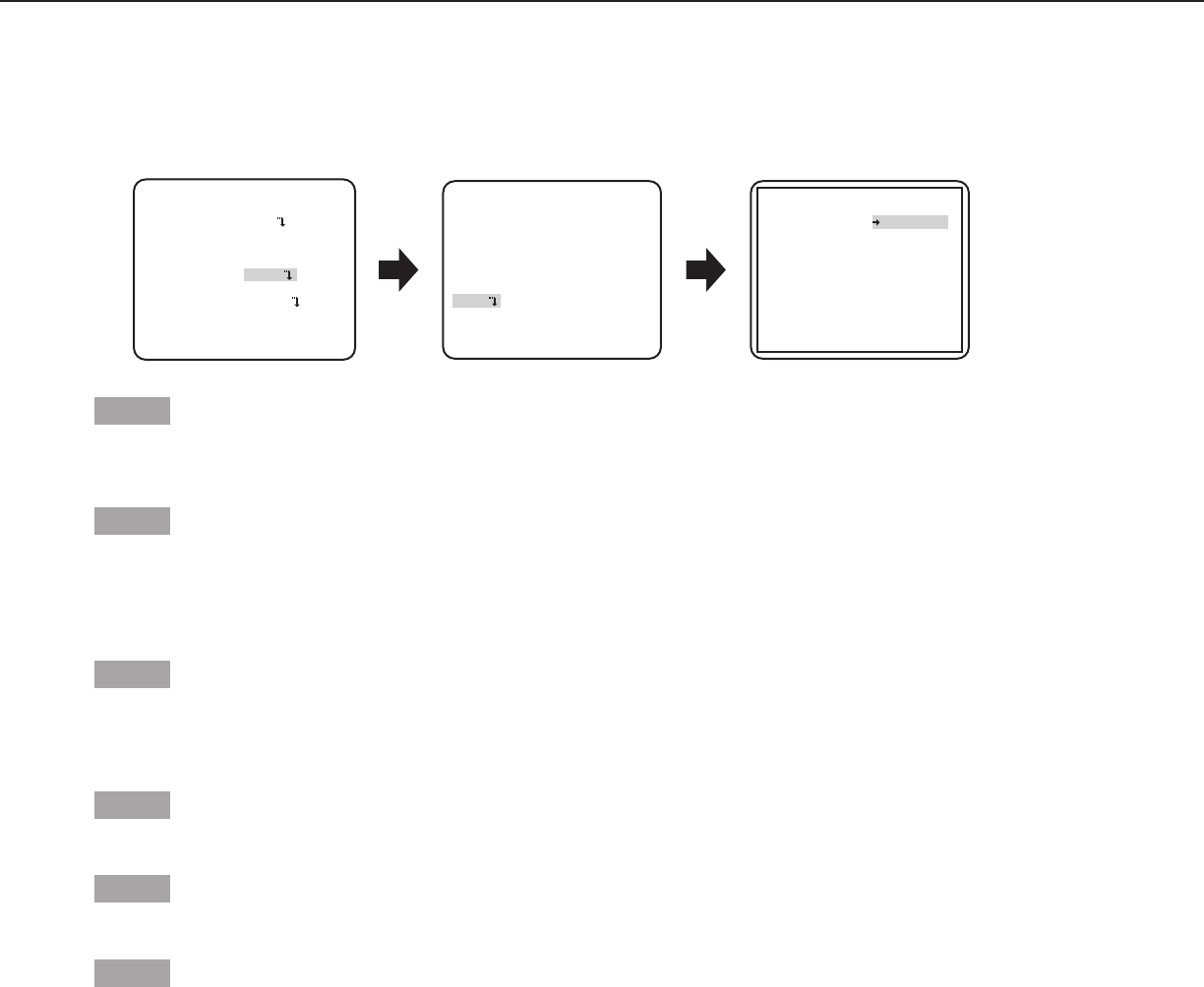
Step 1
Move the cursor to “PRIVACY ZONE”, select “ON (1)” or “ON (2)”, and press the [SET] button.
→ The “ZONE NUMBER” screen appears.
Step 2
Move the cursor to the number at the right of the title and select the zone number using the [RIGHT] or [LEFT] button.
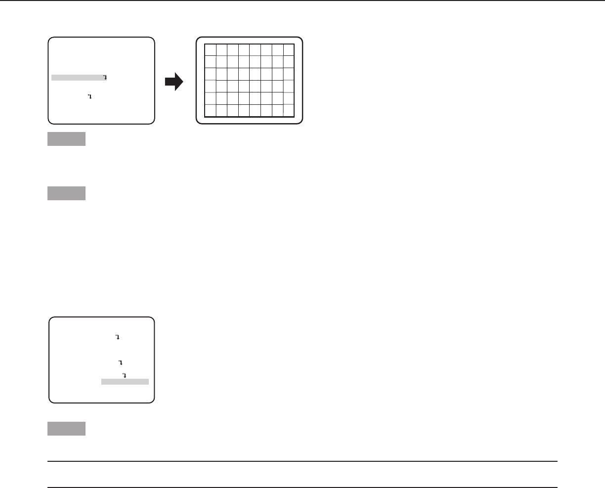
Step 3
Move the cursor to “POSITION” and press the [SET] button.
Step 4
Press the [UP], [DOWN], [RIGHT], and [LEFT] buttons to determine the left upper position of the zone to be set and press the [SET]
button.
“SYSTEM SETUP” screen
**SYSTEM SETUP**
SYNC INT
PRIVACY ZONE OFF
STABILIZER OFF
EL-ZOOM OFF
UPSIDE-DOWN OFF
- +
LDC I...... 0
RET TOP END
22
Step 5
Press the [UP], [DOWN], [RIGHT], and [LEFT] buttons to determine the lower right position of the zone to be set and press the [SET]
button.
→ An asterisk “*” will be displayed after the number and the zone setting will be saved.
Step 6
When “ON (2)” is selected for “PRIVACY ZONE”, the mosaic level may be adjusted. The mosaic level may be set through “ZONE
LEVEL”. (Range: 1 to 4)
Note:
• Todeleteazone,selectthezonenumberandpressthe[SET]buttonaftermovingthecursorto“DEL”.
• Tochangethesettingsofazone,selectthezonenumberandrepeatfromstep3.
12. Image stabilizer setting [STABILIZER]
Whether or not to enable the image stabilizer is determined.
This function is effective for the case that the camera is installed at a place with slight shaking.
ON: Enables the image stabilizer.
OFF (default): Disables the image stabilizer.
Important:
• When“ON”isselectedfortheimagestabilizer,theviewanglebecomesnarrowerandtheresolutionbecomeslower.When“ON”
is selected for the image stabilizer, check the view angle and resolution at camera installation.
• Theimagestabilizerfunctionmaynotworkforthefollowingsubjectsorconditions.
•Darksubject
•Lesscontrastysubject(e.g.whitewall)
•Subjectshakingatexcessivespeed
•Largeamplitudeimageshaking
13. Electronic zoom setting [EL-ZOOM]
Whether or not to use the electronic zoom is determined.
ON: Uses the electronic zoom.
OFF (default): Does not use the electronic zoom.
When “ON” is selected, the zoom factor and the panning/tilting settings can be configured.
Follow the procedure below.
**EL-ZOOM**
**EL-ZOOM** **EL-ZOOM**
PUSH SET
PUSH SET
ZOOM
PAN/TILT
PUSH SET
PUSH SET
ZOOM
PAN/TILT
PUSH SET
PUSH SET
ZOOM
PAN/TILT
U ZOOM D U TILT D/L PAN R
“SYSTEM SETUP” screen “EL-ZOOM” screen Pan/tilt setting screenZoom setting screen
RET TOP END RET TOP END RET TOP END
OFF
**SYSTEM SETUP**
SYNC INT
PRIVACY ZONE
STABILIZER OFF
EL-ZOOM ON
UPSIDE-DOWN OFF
- +
LDC I...... 0
RET TOP END
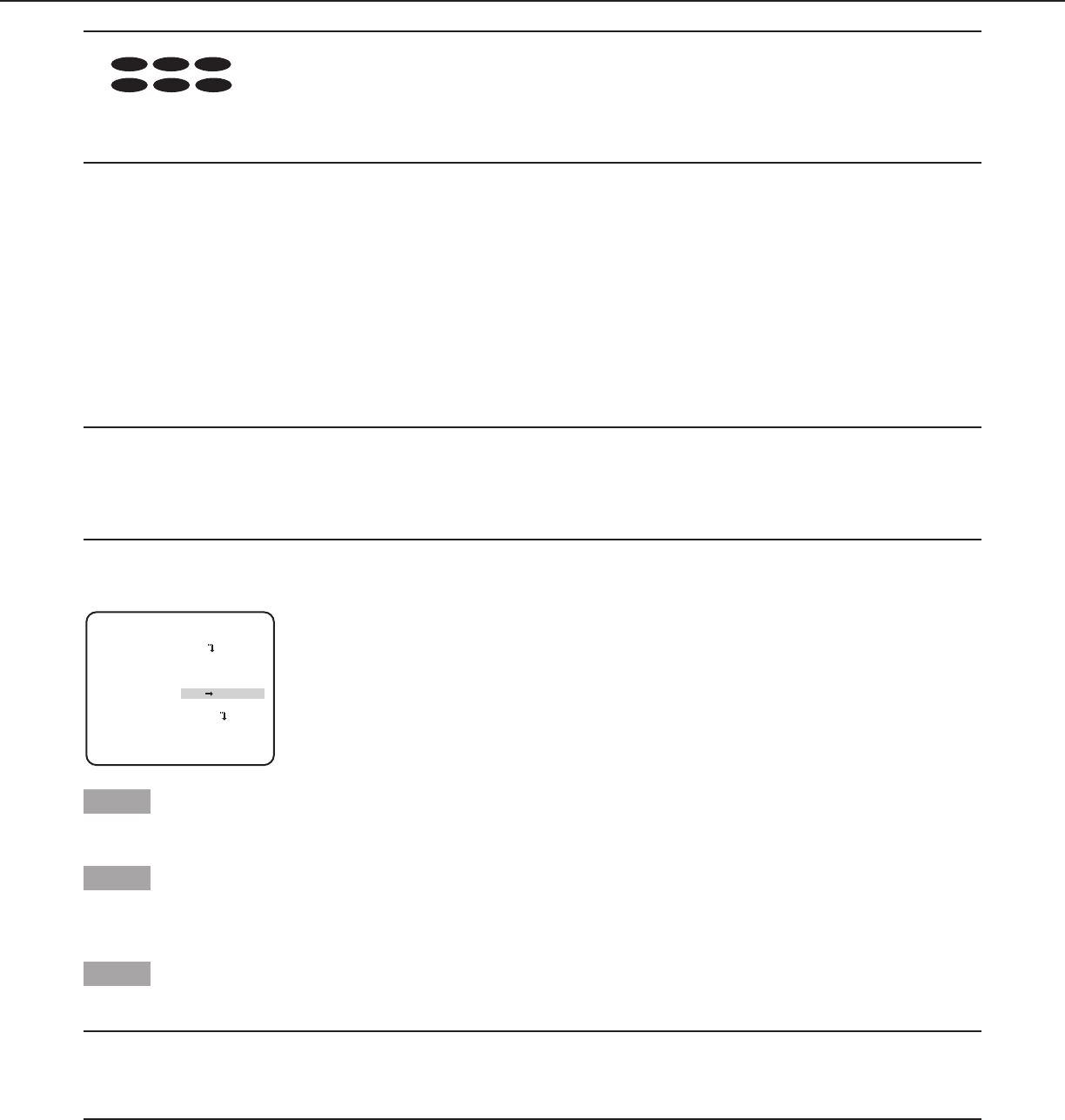
Step 1
Move the cursor to “EL-ZOOM” and select “ON” and press the [SET] button.
→ The “EL-ZOOM” screen appears.

23
Step 2
Move the cursor to “→ PUSH SET” of “ZOOM” and press the [SET] button.
→ The zoom setting screen appears.
Step 3
Adjust the angular field of view by changing the electronic zoom factor (up to 2x) using the [UP] or [DOWN] button, and press the [SET]
button.
Note:
• Whenthezoomfactorisincremented,resolutionwillbedeteriorated.
Step 4
Move the cursor to “→ PUSH SET” of “PAN/TILT” and press the [SET] button.
→ The pan/tilt setting screen appears.
Step 5
Press the [UP], [DOWN], [RIGHT], and [LEFT] buttons to determine the position of the area to be set and press the [SET] button.
The position can be changed in the range of zoom factor set in the zoom setting screen.
14. Upside-down setting [UPSIDE-DOWN]
ON: The video image can be reversed upside down.
OFF (default): The video image cannot be reversed upside down.
15. Lens distortion correction [LDC]
The image may be distorted depending on the lens used and the zoom factor. By adjusting the lens distortion correction setting, the
distorted image can be converted to match the square monitor and achieve effects desired by the user.
Note:
•Dependingonthelensused,completecorrectionmaynotbeachieved.
24
Back focus setting [BACK-FOCUS SETUP]
CW324L
CW314L
CW304L
CF314L
CF304L
CW324L
CW314L
CW304L
CF314L
CF304L
CW324L
CW314L
CW304L
CF314L
CF304L
Selects the back focus setting type and performs fine adjustment. The following setting can be configured on the “BACK-FOCUS
SETUP” screen displayed from the top screen. Refer to page 5 for how to call up the screen.
The lens adjustment shall be performed before the back focus adjustment.
16. Auto back focus setting [ABF]
Move the cursor to “→ PUSH SET” of “ABF” and press the [SET] button.
→ The auto back focus function provides back focus adjustment to automatically focus on a subject located in the center of the
screen.
17. Manual back focus setting [MANUAL-ADJ]
To fine adjust the back focus, move the cursor to “MANUAL-ADJ”, press the [SET] button, and press the [RIGHT] or [LEFT] button to
adjust the back focus manually.
18. Auto back focus settings for switching between color and black-and-white
modes [CL↔B/W]
Move the cursor to “C/L← →B/W” and select the back focus adjustment type from the following:
AUTO: Adjusts the back focus function automatically and corrects out of focus when switching between color and black-and-white
images.
FIX (default): The back focus function will not adjust automatically when switching between color and black-and-white images.
Important:
• Theautobackfocusfunctionisusedforbackfocusadjustmentatinstallationandforfocuscorrectionatswitchingbetweenthe
color and black-and-white modes after installation. This function is not a function that is supposed to be operated continuously
such as the auto focus function.
• Whenfocusmissingoccursduetosecularchangeinthelensandinstallationenvironmentorperipheraltemperaturechange,the
back focus adjustment is required again.
• Thefollowingarerecommendationforbackfocussettinginaccordancewithsubjects.
For such case (subject conditions) Select this (recommendation)
Back focus adjustment
“C/L← → B/W” switching
• Normalsubject “ABF” “AUTO”
• Frequentlymovingsubject Fine adjustment with “MANUAL-ADJ” after
“ABF”
“FIX”
• Subjectwithremarkableilluminancechange
• Subjectwithlowilluminance
• Toobrightorreflectivesubject
• Subjectthroughawindow
• Placewherethelenseasilybecomesdirty
• Subjectwithlesscontrastsuchaswhitewall
• Subjectwithremarkabledepth
• Subjectwithheavyflicker
• Subjectwithhorizontallyparallellinessuchasashutter
Note:
• Thebackfocusadjustmentcanbealsoperformedthroughtheoperationbuttons.
“BACK-FOCUS SETUP” screen
**BACK-FOCUS SETUP**
ABF PUSH SET
MANUAL-ADJ
C/L B/W FIX
RET TOP END
25
Special menu setting [SPECIAL SETUP]
The special menu setup is performed including the setting of the camera image quality and the communication configuration when a
receiver is used. The following settings are to be configured on the “SPECIAL SETUP” screen displayed from the top screen.
Refer to page 5 for how to call up the screen.
19. Chroma level adjustment [CHROMA GAIN]
Press the [RIGHT] or [LEFT] button to adjust the color density of the camera image. When the level indicator moves in the “+”
direction, the color becomes deeper, and when the level indicator moves in the “–” direction, the color becomes lighter. Be sure to
view a vector chromaticity indicator or a video monitor when the adjustment is performed.
20. Aperture level adjustment [AP GAIN]
Press the [RIGHT] or [LEFT] button to adjust the image quality. When the level indicator moves in the “+” direction, the image
becomes sharper, and when the level indicator moves in the “–” direction, the image becomes softer. Be sure to view a video monitor
when the adjustment is performed.
Note:
•Moire(interferencefringes)maybeobservedwhenshootingasubjectwithfinepatternsuchasacarpetoracurtain.Insucha
case, move the indicator in the “-” direction to reduce moire.
21. Pedestal level adjustment [PEDESTAL]
Press the [RIGHT] or [LEFT] button to adjust the pedestal level of the camera. When the level indicator moves in the “+” direction,
the image becomes brighter, and when the level indicator moves in the “–” direction, the image becomes darker. Be sure to view a
waveform monitor or a video monitor when the adjustment is performed.
22. Pixel compensation [PIX OFF]
Flaws of pixel in the displayed camera image are corrected. Up to 16 points can be corrected.
CW324L
CW314L
CW304L
CF314L
CF304L
In order to see more clearly the flaws of pixel, please cover the lens with objects to make the image black totally.
Follow the procedure below.
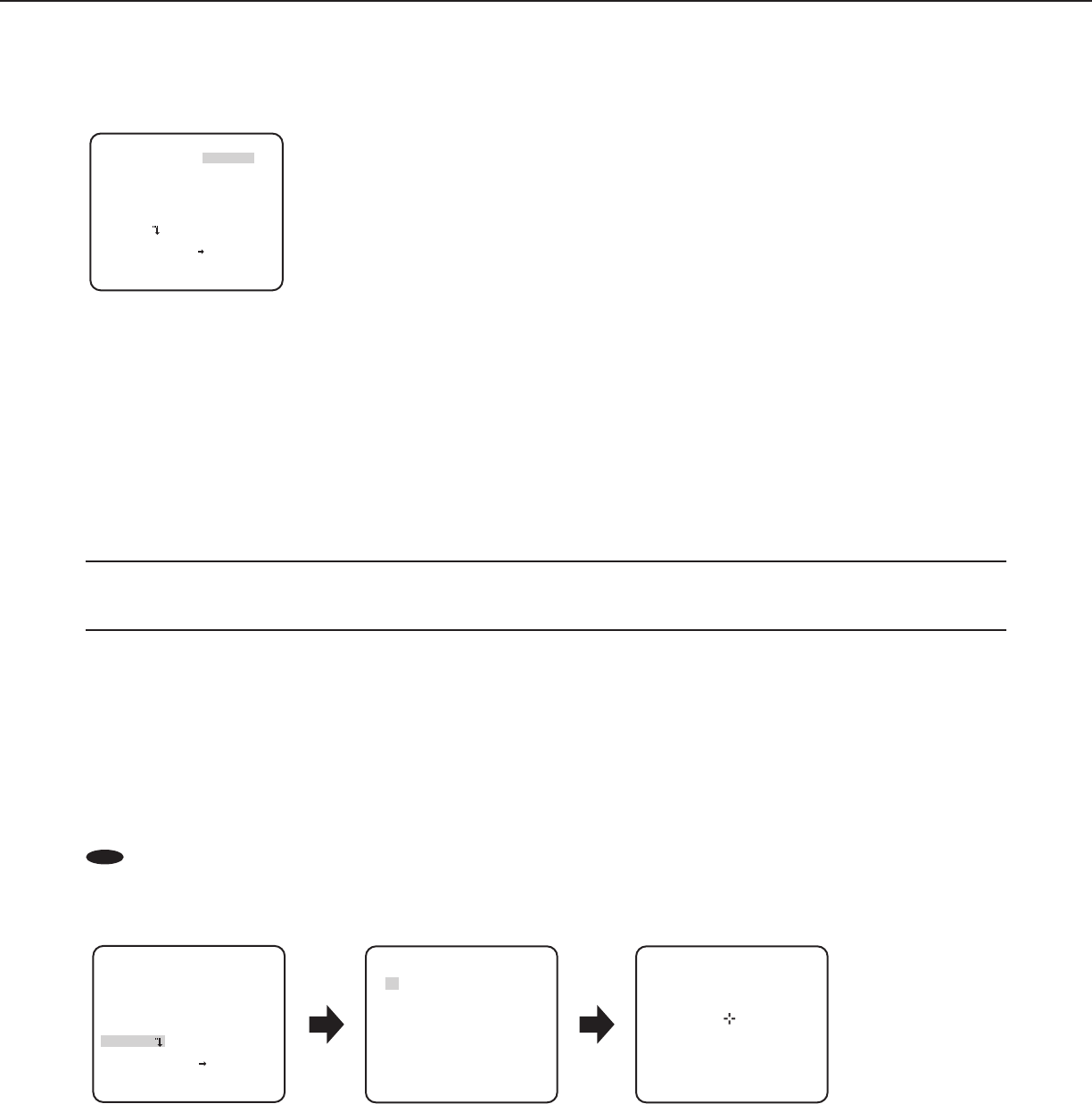
**PIX OFF**
1 2 3 4
5 6 7 8
9 10 11 12
13 14 15 16
1
DEL
000 000
“SPECIAL SETUP” screen “PIX OFF” screen
Pixel compensation positioning screen
RET TOP END
**SPECIAL SETUP**
CHROMA GAIN
....I..160
AP GAIN ..I.... 32
PEDESTAL .I..... 16
- +
PIX OFF
CAMERA RESET PUSH SET
SER.NO. XXXXXXXX
RET TOP END
“SPECIAL SETUP” screen
**SPECIAL SETUP**
CHROMA GAIN
....I..160
AP GAIN ..I.... 32
PEDESTAL .I..... 16
- +
PIX OFF
CAMERA RESET PUSH SET
SER.NO. XXXXXXXX
RET TOP END

26
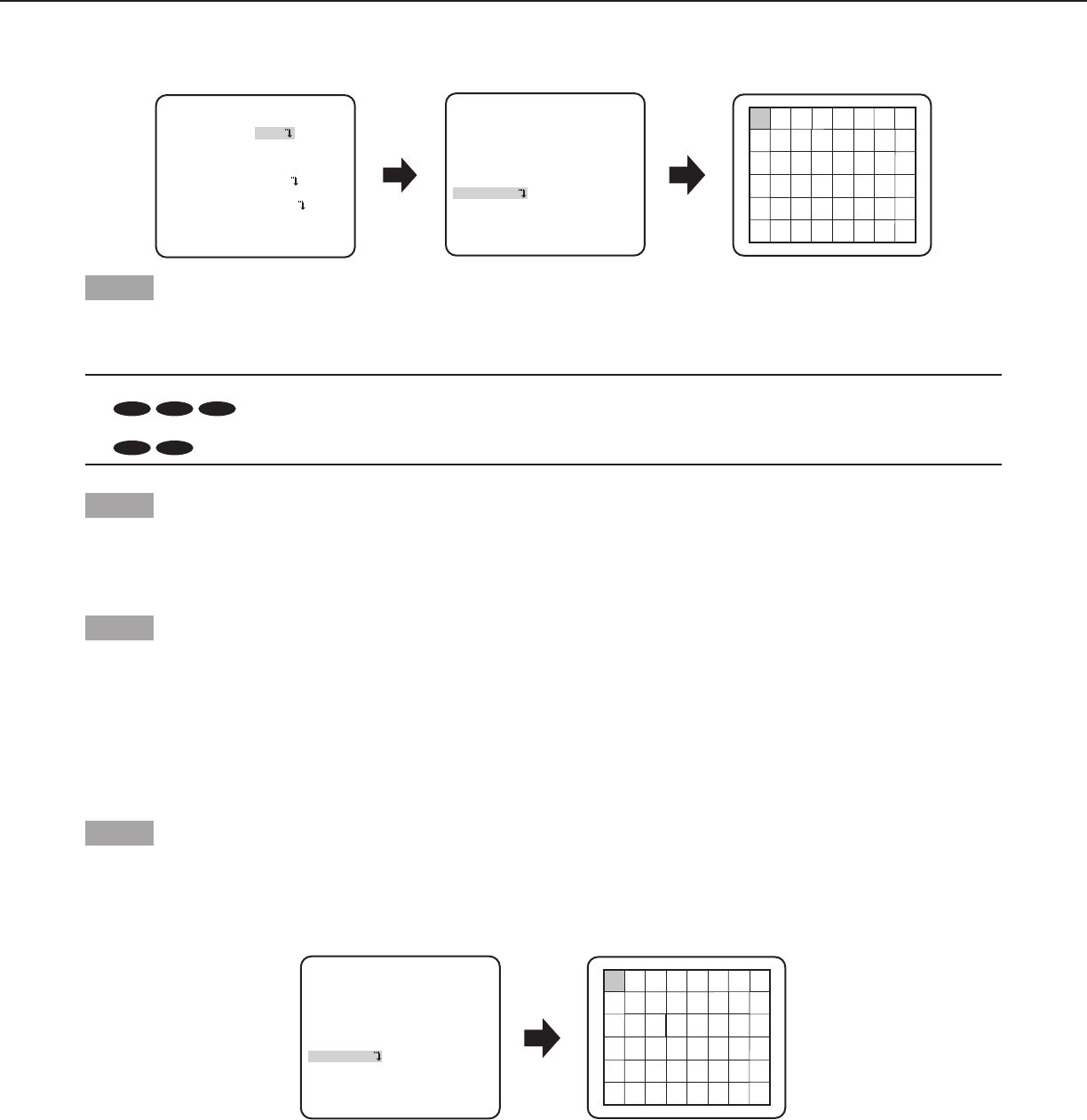
Step 1
Move the cursor to “PIX OFF” and press the [SET] button.
→ The “PIX OFF” screen appears.
Step 2
Select a number (1 to 16) with which a pixel compensation point is registered and press the [SET] button.
→ The pixel compensation positioning screen appears.
Step 3
Press the [UP], [DOWN], [RIGHT], and [LEFT] buttons to move the crosshair cursor to the center of the flaw to be corrected and press
the [SET] button.
→ The flaw is corrected and the pixel compensation point is registered. The “PIX OFF” screen appears again. An asterisk “*” is
attached at the right side of the number when registration is completed. The coordinate is expressed in figures.
Note:
•Tocleartheregisteredpixelcompensationpoint,movethecursorto“1”oftherightof“DEL”,usethe[RIGHT] and [LEFT] buttons
to select the number with which the target pixel compensation point is registered and press the [SET] button. The registered pixel
compensation point is cleared, and an asterisk “*” at the right side of the number disappears.
23. Default resetting [CAMERA RESET]
The settings in the setup menu are restored to the default settings.
Move the cursor to “→ PUSH SET” of “CAMERA RESET” and hold down the [SET] button for more than 2 seconds to enter the next
screen.
To return to the previous screen without resetting, move the cursor to “NO” and press the [SET] button. To restore the default settings,
move the cursor to “YES” and press the [SET] button.
Note:
•Thedataoftheregisteredpixelcompensationpointsisnotcleared.
•To set whether to reset the camera, select “YES” or “NO” by using the [SET] button. To set with a controller, refer to the
instruction manual of the controller.
24. Serial number viewing [SER.NO.]
Displays the serial number of this product.

27
Camera language selection [LANGUAGE SETUP]
A language for the setup menu is selected from the following: The language selection can be made on the “LANGUAGE SETUP”
screen displayed from the top screen.
Refer to page 5 for how to call up the screen.
Move the cursor to “LANGUAGE” and press the [RIGHT] or [LEFT] button to select the target language, then move the cursor to “SET”,
and press the [SET] button.
Select the target language from the following.
JAPANESE/ENGLISH (default)/FRANÇAIS/ESPAÑOL/DEUTSCH/ITALIANO/PУCCKИЙ/中文
Note:
•Whenthelanguageischanged,thespecifiedcameratitleiscleared.
“LANGUAGE SETUP” screen
**LANGUAGE SETUP**
LANGUAGE ENGLISH
SET
RET TOP END
28
Shortcut operation
Use of a system controller with the “Camera function” button allows users to perform the shortcut settings with use of the numeric
keypad and camera function button. The available shortcut operations with this unit are shown as follows.
Systemcontrolleroperation Setting contents
[9] + [0] + [Camera function] Black-and-white control (D&N) ON
[9] + [1] + [Camera function] Black-and-white control (D&N) OFF
[9] + [2] + [Camera function] Black-and-white control (D&N) AUTO1
[9] + [3] + [Camera function] Camera title (CAMERA ID) ON
[9] + [4] + [Camera function] Camera title (CAMERA ID) OFF
[9] + [8] + [Camera function] Electronic zoom ON
[9] + [9] + [Camera function] Electronic zoom OFF
[1] + [6] + [8] + [Camera function] Black-and-white control (D&N) AUTO2
[1] + [6] + [9] + [Camera function] Iris of lens (IRIS) OPEN
[1] + [7] + [0] + [Camera function] Iris of lens (IRIS) CLOSE
[1] + [7] + [1] + [Camera function] Electronic shutter (SHUTTER) ON
CW324L
CW314L
CW304L
CF314L
CF304L
CW324L
CW314L
CW304L
CF314L
CF304L
CW324L
CW314L
CW304L
CF314L
CF304L
[1] + [7] + [2] + [Camera function] Electronic shutter (SHUTTER) OFF
CW324L
CW314L
CW304L
CF314L
CF304L
CW324L
CW314L
CW304L
CF314L
CF304L
CW324L
CW314L
CW304L
CF314L
CF304L
[1] + [7] + [3] + [Camera function] Electronic shutter speed, 1 step faster
CW324L
CW314L
CW304L
CF314L
CF304L
CW324L
CW314L
CW304L
CF314L
CF304L
CW324L
CW314L
CW304L
CF314L
CF304L
[1] + [7] + [4] + [Camera function] Electronic shutter speed, 1 step slower
CW324L
CW314L
CW304L
CF314L
CF304L
CW324L
CW314L
CW304L
CF314L
CF304L
CW324L
CW314L
CW304L
CF314L
CF304L
[1] + [7] + [5] + [Camera function] Gain adjustment (AGC) ON
[1] + [7] + [6] + [Camera function] Gain adjustment (AGC) OFF
[1] + [7] + [7] + [Camera function] Electronic sensitivity up (SENS UP) FIX ON
CW324L
CW314L
CW304L
CF314L
CF304L
CW324L
CW314L
CW304L
CF314L
CF304L
CW324L
CW314L
CW304L
CF314L
CF304L
[1] + [7] + [8] + [Camera function] Electronic sensitivity up (SENS UP) FIX OFF
CW324L
CW314L
CW304L
CF314L
CF304L
CW324L
CW314L
CW304L
CF314L
CF304L
CW324L
CW314L
CW304L
CF314L
CF304L
[1] + [7] + [9] + [Camera function] Electronic sensitivity, 1 step up (FIX)
CW324L
CW314L
CW304L
CF314L
CF304L
CW324L
CW314L
CW304L
CF314L
CF304L
CW324L
CW314L
CW304L
CF314L
CF304L
[1] + [8] + [0] + [Camera function] Electronic sensitivity, 1 step down (FIX)
CW324L
CW314L
CW304L
CF314L
CF304L
CW324L
CW314L
CW304L
CF314L
CF304L
CW324L
CW314L
CW304L
CF314L
CF304L
[1] + [8] + [1] + [Camera function] Electronic sensitivity up (SENS UP) AUTO ON
[1] + [8] + [2] + [Camera function] Electronic sensitivity up (SENS UP) AUTO OFF
[1] + [8] + [3] + [Camera function] Electronic sensitivity, 1 step up (AUTO)
[1] + [8] + [4] + [Camera function] Electronic sensitivity, 1 step down (AUTO)
[1] + [9] + [0] + [Camera function] Time for switching at D&N AUTO, 2 seconds
[1] + [9] + [1] + [Camera function] Time for switching at D&N AUTO, 10 seconds
[1] + [9] + [2] + [Camera function] Time for switching at D&N AUTO, 30 seconds
[1] + [9] + [3] + [Camera function] Time for switching at D&N AUTO, 60 seconds
[2] + [0] + [1] + [Camera function] Image stabilizer (STABILIZER) ON
[2] + [0] + [2] + [Camera function] Image stabilizer (STABILIZER) OFF
[2] + [1] + [3] + [Camera function] Scene file 1
[2] + [1] + [4] + [Camera function] Scene file 2
[2] + [1] + [5] + [Camera function] Gain (AGC), 1 step up
[2] + [1] + [6] + [Camera function] Gain (AGC), 1 step down

http://panasonic.net
Importer's name and address to follow EU rules:
Panasonic Testing Centre
Panasonic Marketing Europe GmbH
Winsbergring 15, 22525 Hamburg F.R.Germany
© Panasonic System Networks Co., Ltd. 2013 sL0313-0 PGQP1452ZA Printed in China
http://panasonic.net
Importer's name and address to follow EU rules:
Panasonic Testing Centre
Panasonic Marketing Europe GmbH
Winsbergring 15, 22525 Hamburg F.R.Germany
© Panasonic System Networks Co., Ltd. 2011
sC1111-0 PGZC1027ZA
http://panasonic.net
Importer's name and address to follow EU rules:
Panasonic Testing Centre
Panasonic Marketing Europe GmbH
Winsbergring 15, 22525 Hamburg F.R.Germany
© Panasonic System Networks Co., Ltd. 2011
sC1111-0 PGZC1027ZA
http://panasonic.net
Importer's name and address to follow EU rules:
Panasonic Testing Centre
Panasonic Marketing Europe GmbH
Winsbergring 15, 22525 Hamburg F.R.Germany
© Panasonic System Networks Co., Ltd. 2011
sC1111-0 PGZC1027ZA
