Panasonic SC HTB520 User Manual To The 616d046c 288b 4f13 9731 5964bd92ac0c
User Manual: Panasonic SC-HTB520 to the manual
Open the PDF directly: View PDF ![]() .
.
Page Count: 28
until
2011/03/07
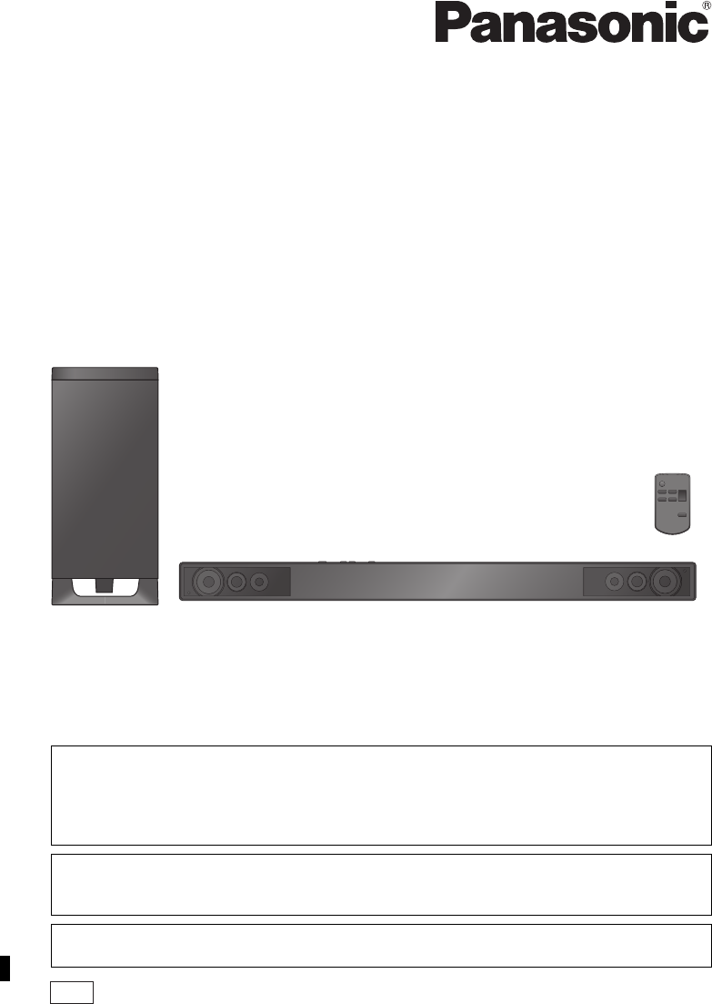
Owner’s Manual
Home Theater Audio System
Model No. SC-HTB520
PP
Dear customer
Thank you for purchasing this product.
For optimum performance and safety, please read these instructions carefully.
Please keep this manual for future reference.
Included Installation Instructions (>10 to 14)
The installation work should be done by a qualified installation specialist.
Before commencing work, carefully read these installation instructions and the operating instructions
to ensure that installation is performed correctly.
(Please keep these instructions. You may need them when maintaining or moving this unit.)
If you have any questions contact
For U.S.A. and Puerto Rico: 1-800-211-PANA (7262)
For Canada: 1-800-561-5505
For U.S.A. and Puerto Rico: The warranty can be found on page 25.
For Canada: The warranty can be found on page 27.
RQTX1278-2Y
SC-HTB520PP_RQTX1278-Y.book Page 1 Friday, March 4, 2011 9:20 AM
2
WARNING:
TO REDUCE THE RISK OF FIRE, ELECTRIC SHOCK OR PRODUCT DAMAGE,
≥DO NOT EXPOSE THIS APPARATUS TO RAIN, MOISTURE, DRIPPING OR SPLASHING AND
THAT NO OBJECTS FILLED WITH LIQUIDS, SUCH AS VASES, SHALL BE PLACED ON THE
APPARATUS.
≥USE ONLY THE RECOMMENDED ACCESSORIES.
≥DO NOT REMOVE THE COVER (OR BACK); THERE ARE NO USER SERVICEABLE PARTS
INSIDE. REFER SERVICING TO QUALIFIED SERVICE PERSONNEL.
CAUTION!
DO NOT INSTALL OR PLACE THIS UNIT IN A BOOKCASE, BUILT-IN CABINET OR IN ANOTHER
CONFINED SPACE. ENSURE THE UNIT IS WELL VENTILATED. TO PREVENT RISK OF ELECTRIC
SHOCK OR FIRE HAZARD DUE TO OVERHEATING, ENSURE THAT CURTAINS AND ANY OTHER
MATERIALS DO NOT OBSTRUCT THE VENTILATION VENTS.
Button-type battery (Lithium battery)
≥Insert with poles aligned.
≥Do not touch the terminals (i and j) with metal objects.
≥Do not recharge, disassemble, remodel, heat or throw into fire.
≥Keep out of reach of children
If any electrolyte should come into contact with your hands or clothes, wash it off thoroughly with water.
If any electrolyte should come into contact with your eyes, never rub the eyes. Rinse eyes thoroughly
with water, and then consult a doctor.
Warning
Risk of fire, explosion and burns. Do not disassemble, heat above 60 oC (140 oF) or incinerate.
The unit should be installed near an accessible AC power outlet, with the power cord connected directly
to it.
To completely disconnect power from the unit, unplug the power cord from the AC power outlet.
<For USA-California only>
This product contains a CR Coin Cell Lithium Battery which contains Perchlorate Material s special
handling may apply.
See www.dtsc.ca.gov/hazardouswaste/perchlorate.
The lightning flash with arrowhead
symbol, within an equilateral triangle,
is intended to alert the user to the
presence of uninsulated “dangerous
voltage” within the product’s
enclosure that may be of sufficient
magnitude to constitute a risk of
electric shock to persons.
The exclamation point within an
equilateral triangle is intended to alert
the user to the presence of important
operating and maintenance
(servicing) instructions in the literature
accompanying the appliance.
CAUTION: TO REDUCE THE RISK OF ELECTRIC
SHOCK, DO NOT REMOVE SCREWS.
NO USER-SERVICEABLE PARTS
INSIDE.
REFER SERVICING TO QUALIFIED
SERVICE PERSONNEL.
CAUTION
RISK OF ELECTRIC SHOCK
DO NOT OPEN
SC-HTB520PP_RQTX1278-Y.book Page 2 Friday, February 11, 2011 11:25 AM
3
Precautions
IMPORTANT SAFETY INSTRUCTIONS
Read these operating instructions carefully before using the unit. Follow the safety instructions on the unit and
the applicable safety instructions listed below. Keep these operating instructions handy for future reference.
1 Read these instructions.
2 Keep these instructions.
3 Heed all warnings.
4 Follow all instructions.
5 Do not use this apparatus near water.
6 Clean only with dry cloth.
7 Do not block any ventilation openings. Install in
accordance with the manufacturer’s instructions.
8 Do not install near any heat sources such as radiators,
heat registers, stoves, or other apparatus (including
amplifiers) that produce heat.
9 Do not defeat the safety purpose of the polarized or
grounding-type plug. A polarized plug has two blades
with one wider than the other.
A grounding-type plug has two blades and a third
grounding prong. The wide blade or the third prong
are provided for your safety. If the provided plug does
not fit into your outlet, consult an electrician for
replacement of the obsolete outlet.
10 Protect the power cord from being walked on or
pinched particularly at plugs, convenience
receptacles, and the point where they exit from the
apparatus.
11 Only use attachments/accessories specified by the
manufacturer.
12 Use only with the cart, stand, tripod,
bracket, or table specified by the
manufacturer, or sold with the
apparatus. When a cart is used, use
caution when moving the cart/
apparatus combination to avoid injury
from tip-over.
13 Unplug this apparatus during lightning storms or
when unused for long periods of time.
14 Refer all servicing to qualified service personnel.
Servicing is required when the apparatus has been
damaged in any way, such as power-supply cord or
plug is damaged, liquid has been spilled or objects
have fallen into the apparatus, the apparatus has
been exposed to rain or moisture, does not operate
normally, or has been dropped.
-If you see this symbol-
Licenses
The model number and serial number of this
product can be found on either the back or the
bottom of the unit.
Please note them in the space provided below
and keep for future reference.
MODEL NUMBER ______________________
SERIAL NUMBER ______________________
User memo:
DATE OF PURCHASE ___________________
DEALER NAME ________________________
DEALER ADDRESS ____________________
______________________________________
TELEPHONE NUMBER __________________
THE FOLLOWING APPLIES ONLY IN CANADA.
This device complies with Industry Canada
licence-exempt RSS standard(s). Operation is
subject to the following two conditions: (1) this
device may not cause interference, and (2) this
device must accept any interference, including
interference that may cause undesired operation
of the device.
Information on Disposal in other Countries
outside the European Union
This symbol is only valid in the
European Union.
If you wish to discard this product,
please contact your local
authorities or dealer and ask for
the correct method of disposal.
Manufactured under license from Dolby Laboratories. Dolby,
Pro Logic, and the double-D symbol are trademarks of Dolby
Laboratories.
Manufactured under license under U.S. Patent #’s:
5,451,942; 5,956,674; 5,974,380; 5,978,762; 6,487,535 &
other U.S. and worldwide patents issued & pending.
DTS and the Symbol are registered trademarks & DTS
Digital Surround and the DTS logos are trademarks of DTS,
Inc. Product includes software.
© DTS, Inc. All Rights Reserved.
HDMI, the HDMI Logo, and High-Definition Multimedia
Interface are trademarks or registered trademarks of HDMI
Licensing LLC in the United States and other countries.
HDAVI Control™ is a trademark of Panasonic Corporation.
VIERA Link™ is a trademark of Panasonic Corporation.
EZ Sync™ is a trademark of Panasonic Corporation.
“x.v.Color” is a trademark.
SC-HTB520
SC-HTB520PP_RQTX1278-Y.book Page 3 Friday, March 4, 2011 9:20 AM

4
Table of Contents
IMPORTANT SAFETY INSTRUCTIONS ............................................................... 3
Licenses ................................................................................................................ 3
Accessories .......................................................................................................... 5
Unit care ................................................................................................................ 5
Control reference guide ....................................................................................... 6
This unit and active subwoofer (Front) .......................................................................................6
This unit and active subwoofer (Rear) .......................................................................................6
Remote control ...........................................................................................................................7
Step 1 Placement ................................................................................................. 8
This unit .....................................................................................................................................8
The active subwoofer .................................................................................................................9
When placing the unit on a wall ...............................................................................................10
When placing the unit in a rack or on a table ...........................................................................13
Step 2 Connections ............................................................................................ 15
Connection to a TV ..................................................................................................................15
Connection from an HDMI compatible device ..........................................................................16
Digital transmitter connection ...................................................................................................16
Step 3 AC power supply cord connection ....................................................... 17
Step 4 Active subwoofer wireless connection ................................................ 17
Using this unit .................................................................................................... 18
3D sound .................................................................................................................................19
Linked operations with the TV
(VIERA LinkTM “HDAVI ControlTM”) ................................................................... 20
Troubleshooting ................................................................................................. 21
Remote control code ................................................................................................................23
Audio information .............................................................................................. 23
Specifications ..................................................................................................... 24
Limited Warranty
(ONLY FOR U.S.A. AND PUERTO RICO) ...................................................... 25
Limited Warranty (ONLY FOR CANADA) ......................................................... 27
Before use
Getting started
Operations
Reference
SC-HTB520PP_RQTX1278-Y.book Page 4 Friday, February 11, 2011 11:25 AM
Before use
5
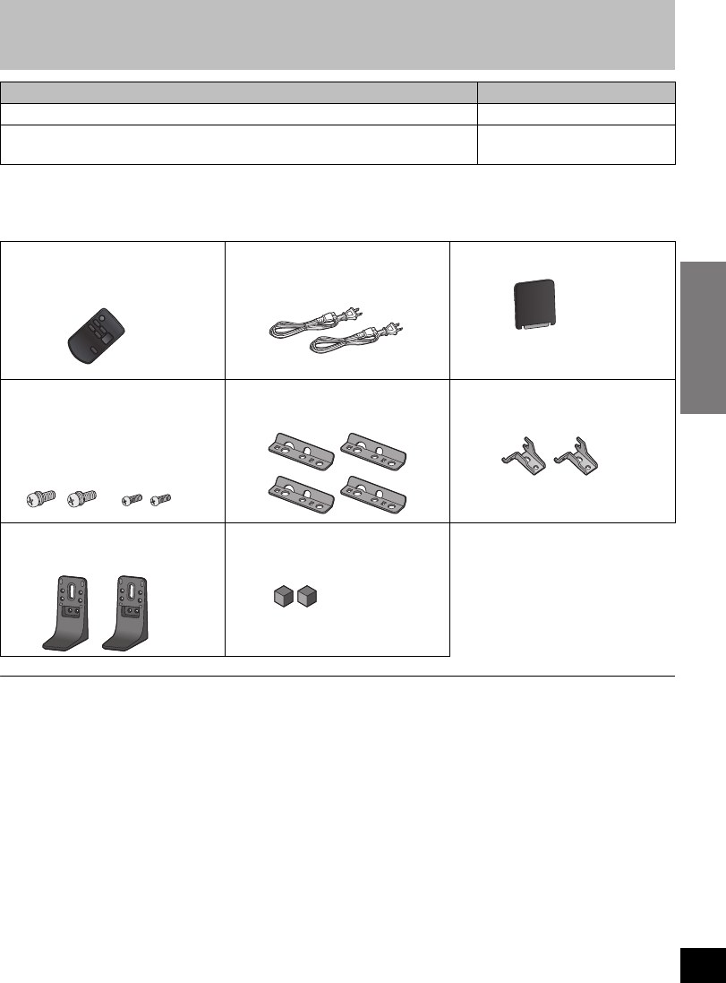
Accessories
Check the supplied accessories before using this unit.
≥Product numbers correct as of January 2011. These may be subject to change.
≥Only for U.S.A. and Puerto Rico:
To order accessories, refer to “Accessory Purchases (United States and Puerto Rico)” on page 26.
For Canada: To order accessories, call the dealer from whom you made your purchase.
≥The supplied AC power supply cord is for use with this unit and the active subwoofer only.
Do not use it with other equipment. Also, do not use cords for other equipment with this unit or the active subwoofer.
Unit care
∫Clean this unit with a soft, dry cloth
≥When dirt is heavy, wring a cloth moistened in water tightly to wipe the dirt, and then wipe it with a dry
cloth.
≥When cleaning this unit, use a fine cloth. Do not use tissues or other materials (towels, etc.) that can fall
apart. Small grains may get stuck inside the speaker cover.
≥Never use alcohol, paint thinner or benzine to clean this unit.
≥Before using chemically-treated cloth, carefully read the instructions that came with the cloth.
≥Before connecting, operating or adjusting this product, please read the instructions completely.
≥The illustrations shown may differ from your unit.
≥Operations in these instructions are described mainly with the remote control, but you can
perform the operations on this unit if the controls are the same.
System SC-HTB520
This unit SU-HTB520
Active subwoofer
(With digital transmitter)
SB-HWA520
∏1 Remote control
(Built-in battery)
(N2QAYC000043)
∏2 AC power supply cord
(K2CB2CB00021)
∏1 Digital transmitter
≥Supplied with the active subwoofer.
∏4 Screws
(With washerk2:
XYN5+J14FJK)
(Without washerk2:
XSN4+8FJK)
∏4 Safety holders
(RFA3321-K)
∏2 Wall mount brackets
(RMQX1082-K)
∏2Stands
(RYQ0853-K)
∏2 Rear Pads
(RMG0850-K)
(ONLY FOR CANADA)
The enclosed French Canadian
label sheet corresponds to the
English display on the remote
control and the top and rear of the
unit.
SC-HTB520PP_RQTX1278-Y.book Page 5 Friday, February 18, 2011 8:48 AM
6
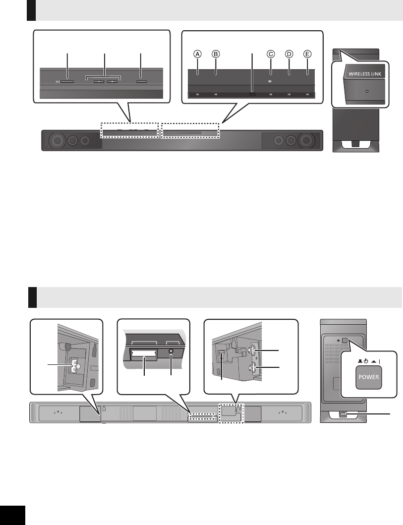
Control reference guide
1Standby/on switch (POWER Í/I)
Press to switch the unit from on to standby
mode or vice versa. In standby mode, the unit
is still consuming a small amount of power.
2 Adjust the Volume of this unit
3 Select the source
“TV” !# “BD/DVD”
≥TV: When the TV is the audio source
(A lights in green)
≥BD/DVD: When the device connected to the
HDMI AV IN terminal is the audio
source
(B lights in amber)
4 LED status indicators (>18)
ATV indicator
BBD/DVD indicator
CDolby Digital indicator
DDTS indicator
EPCM or LPCM indicator
5 Remote control signal sensor
Remote control operation range
Distance:
Within approx. 7 m (23 ft.) directly in front
Angle:
Approx. 30oleft and right
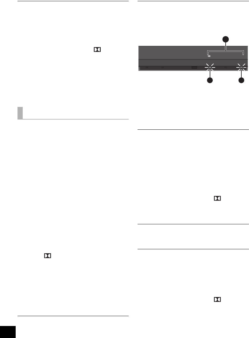
6 WIRELESS LINK indicator (>17)
1 AC IN terminal (>17)
2 Digital transmitter dock (>16)
3 Ir SYSTEM terminal
(Only for use with the optional IR Blaster. (>8))
4 OPTICAL DIGITAL AUDIO IN terminal (>15)
5 HDMI AV OUT terminal (ARC compatible)
(>15)
6 HDMI AV IN terminal (>16)
7 Active subwoofer on/off button
This unit and active subwoofer (Front)
PO W ER VO LU M E
IN P U T S E L E C T O R
TV BD /D VD DDTS
PCM
213
45
6
This unit and active subwoofer (Rear)
Ir SYSTEMDIGITAL TRANSMITTER
17
4
5
6
1
23
SC-HTB520PP_RQTX1278-Y.book Page 6 Friday, February 11, 2011 11:25 AM
Before use
7
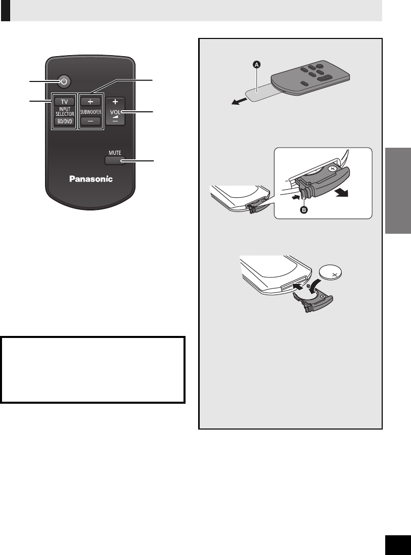
1 Turn this unit on or off (>18)
2 Select the source (>18)
≥[TV]:
Select the TV as the source
≥[BD/DVD]:
Select the device connected to the HDMI AV
IN terminal as the source
3 Adjust the output level of the active subwoofer
(>18)
4 Adjust the volume of this unit (>18)
5 Mute the sound (>18)
Remote control
CAUTION
Danger of explosion if battery is incorrectly
replaced. Replace only with the same or
equivalent type recommended by the
manufacturer. Dispose of used batteries
according to the manufacturer’s instructions.
1
2
3
4
5
Remove the insulation sheet A before using.
∫To replace a button-type battery
1While pressing the stopper B, pull out the
battery holder.
2Set the button-type battery with its (i) mark
facing upward and then put the battery holder
back in place.
≥When the button-type battery runs down,
replace it with a new battery (part number:
CR2025). The battery should normally last
about 1 year, however, this depends on how
frequently the unit is used.
≥Keep the button-type battery out of reach of
children to prevent swallowing.
≥Do not heat or expose to flame.
≥Do not leave the battery(ies) in an automobile
exposed to direct sunlight for a long period of
time with doors and windows closed.
SC-HTB520PP_RQTX1278-Y.book Page 7 Friday, February 11, 2011 11:25 AM
8
E.g.
≥If irregular coloring occurs on your TV, turn the TV off for about 30 minutes. If it persists, move this unit further away from the TV.
≥Do not use this unit in a metal cabinet.
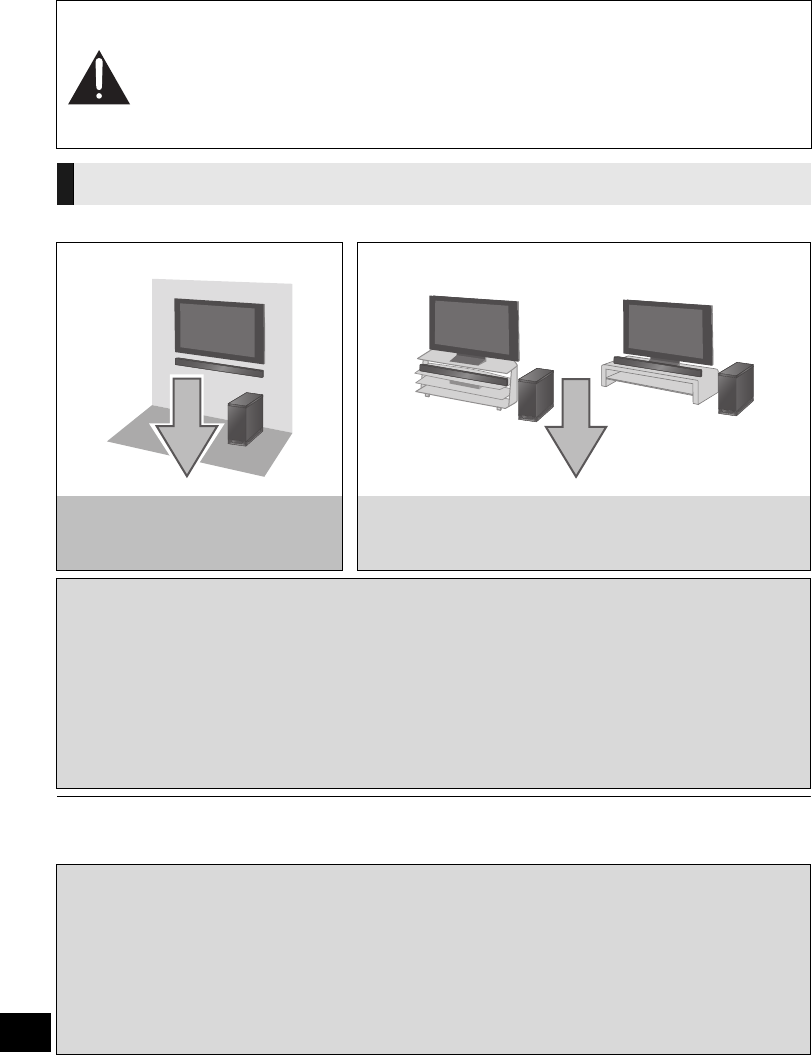
Step 1 Placement
Caution
≥This unit and the active subwoofer are to be used only as indicated in these
instructions. Failure to do so may lead to damage to the amplifier and/or the
speakers, and may result in the risk of fire. Consult a qualified service person if
damage has occurred or if you experience a sudden change in performance.
≥Do not attempt to attach this unit to a wall using methods other than those described
in this manual.
This unit
On the wall In a rack or on a table
Page 10
Refer to “When placing the unit on a
wall”
Page 13
Refer to “When placing the unit in a rack or on a table”
∫When placing the unit in front of the TV.
This unit may block or interfere with the TV’s various sensors (C.A.T.S.(Contrast Automatic Tracking
System) sensor, remote control sensor, etc.) and the 3D Eyewear transmitters on a 3D compatible TV.
Depending on how this unit is placed, this unit might block the TV’s remote control signal sensor.
If the stands are being used
≥Change the height of the stands and/or move this unit farther away from the TV. If the TV still does not
function correctly, try removing the stands.
If the stands are not used
≥Move this unit farther away from the TV. If the TV still does not function correctly, try using it in a rack or
in the wall mount position.
∫If the TV’s remote control sensor is blocked by this unit.
Try using the TV’s remote control from a different angle. If the problem persists, you can use the optional
Panasonic IR Blaster (SH-WR10) to relay the signal to the TV.
≥The optional Panasonic IR Blaster (SH-WR10) is only compatible with Panasonic TVs.
Purchase SH-WR10 (Accessory IR Blaster) at selected dealers or online by visiting our website at:
http://www.panasonic.com
or in Canada: http://www.panasonic.ca
For details, please refer to the operating instructions for the optional Panasonic IR Blaster.
≥Do not use the IR Blaster if the TV’s remote control sensor is not blocked by this unit.
SC-HTB520PP_RQTX1278-Y.book Page 8 Friday, February 11, 2011 11:25 AM
Getting started
9
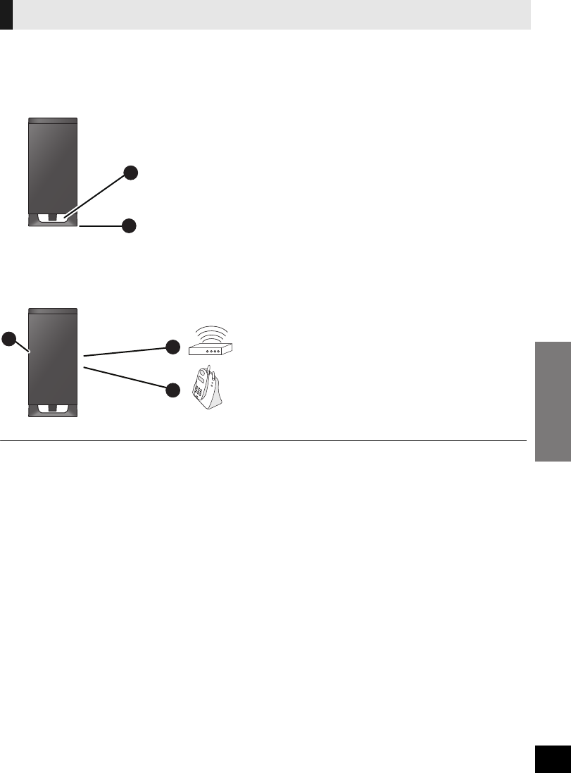
Place the active subwoofer approx. 30 cm (1113/16z) away from the TV.
≥If the TV is Wifi compatible, place the active subwoofer approx. 2 m (61/2 ft) away from the TV.
∫When carrying the active subwoofer
∫Distance with other devices
To avoid interference, maintain the following distances between the active subwoofer and other
electronic devices that use the same radio frequency (2.4 GHz band).
≥Place the active subwoofer within a few meters of this unit, and in a horizontal position with the top panel faced upward.
≥To allow for proper ventilation and to maintain good airflow around the active subwoofer, position it with at least 5 cm (2z) of space
on all sides.
≥Do not use the active subwoofer in a metal cabinet.
≥Placing the active subwoofer too close to the walls, and corners can result in excessive bass. Cover walls and windows with thick
curtains.
The active subwoofer
ADo not hold the active subwoofer from this
opening.
The parts inside (speaker system) may be damaged.
BAlways hold the bottom of the active subwoofer when
moving it.
CActive subwoofer
DWireless LAN: approx. 2 m (61/2 ft)
ECordless phone and other electronic devices:
approx. 2 m (61/2 ft)
A
B
CD
E
SC-HTB520PP_RQTX1278-Y.book Page 9 Friday, February 11, 2011 11:25 AM

10
Safety Precautions
WARNING
Ensure that the installation location is strong enough to support long-term use.
≥If its strength becomes insufficient over the course of long-term use, the unit may drop, possibly causing injury.
The installation work should be done by a qualified installation specialist.
≥Incorrect installation may cause equipment to fall, and personal injury may result.
Include a safety factor when considering the strength of the proposed installation location.
≥If strength is not sufficient the equipment may fall, and personal injury may result.
Do not install in a location that cannot bear the load.
≥If the installation location lacks sufficient strength, the equipment may fall.
Do not modify the wall mount brackets.
≥Otherwise the unit may fall and become damaged, and personal injury may result.
Install the unit by taking only the steps which are specified in these instructions: Do not install it in any other way.
≥Otherwise the unit may drop and become damaged, and personal injury may result.
Do not install in a location other than a vertical wall.
≥Otherwise the unit may drop and become damaged, and personal injury may result.
CAUTION
Do not install in any locations subject to humidity, dust, smoke, steam or heat or under an air conditioner where water may
drip onto the unit.
≥This may have an adverse effect on the unit and cause fire or electric shock.
Leave a clearance between the rear panel and the wall.
≥The unit has air ventilation holes at the front and rear. Covering these may result in a fire.
Install the mounting screws and power cable in such a way that they will not make contact with metal objects or wiring
inside the wall.
≥Electric shocks may result from contact with any metal objects inside the wall.
For installation, use the special-purpose constituent parts.
≥Otherwise, the unit may fall off the wall, and personal injury may result.
When removing this unit, remove the wall mounting screws as well.
≥Otherwise the mounting screws may get caught and personal injury may result.
To operate this unit safely, install it at an appropriate height.
≥Otherwise the unit may fall, and personal injury may result.
Preparation
Commercially available components (not supplied)
≥Screws for wall mounting ................................................................................................................... k 6
jUse commercially available screws with a nominal diameter of 4.0 mm (5/32q) that are suited to the wall material
(wood, steel frame, concrete etc.) you are attaching the wall mount brackets to.
≥Fall prevention cord............................................................................................................................ k 2
≥Screw eyes (to attach the fall prevention cord) .................................................................................. k 2
≥To prevent damage or scratches, lay down a soft cloth and perform the assembly on it.
≥Take sufficient care to ensure safety around you when performing the assembly and installation work or
while moving about during the course of the work.
≥Attach using techniques suited to the structure and materials of the installation location.
≥Ensure that there are no electrical cables or pipes in the wall before hanging this unit.
≥To ensure correct unit performance and prevent trouble, do
not install at any of the following locations:
jNear sprinklers or fire/smoke detectors
jWhere there is a risk of exposure to vibration or impact
jNear high-voltage wires or dynamic power supplies
jNear sources of magnetism, heat, water vapour or soot
jLocations exposed to air blown from heating equipment
jWhere droplets of condensation from an air conditioner or
another unit may form.
≥Do not hold this unit in one hand to avoid injury by dropping
this unit when carrying.
≥When screwing down the parts, ensure that the screws are
neither insufficiently tightened nor over tightened.
≥Improper attachment may result in damage to the wall and
this unit.
When placing the unit on a wall
Professional installation is required.
The installation should never be done by any other than a qualified installation specialist.
PANASONIC DISCLAIMS ANY PROPERTY DAMAGE AND/OR SERIOUS INJURY, INCLUDING
DEATH RESULTING FROM IMPROPER INSTALLATION OR INCORRECT HANDLING.
≥Be sure to install this unit as indicated within this Owner’s Manual.
SC-HTB520PP_RQTX1278-Y.book Page 10 Friday, February 18, 2011 8:48 AM
Precautions
Getting started
11
1Use the measurements indicated below to identify the screwing positions on
the wall.
≥Position the unit with at least 50 mm (2q) of space above the unit. If not, it may not be possible to access the buttons on this unit.
2Attach the wall mount brackets to the wall.
≥The position in the wall where the screw is to be attached as well as the screw should be capable of supporting over 33 kg
(72.8 lbs).
≥Be sure to use a spirit level to ensure that both screwing positions are horizontal to each other.
≥Keep the screws out of reach of children to prevent swallowing.
≥Keep the wall mount brackets out of reach of children to prevent swallowing.
3Complete all the necessary connections to this unit. (>15 to 17)
≥Connect the AC power supply cord to this unit, but do not connect it to the household AC outlet until the installation is completed.
4Attach the rear pads to the rear of the unit.
≥Keep the rear pads out of reach of children to prevent swallowing.
5Attach a cord (not supplied) to 2 safety holders.
≥Use a cord which is capable of supporting over 33 kg (72.8 lbs).
≥Keep the safety holders out of reach of children to prevent swallowing.
AWall mount bracket
252 mm (929/32)257 mm (101/8) 233.5 mm (913/64) 275.5 mm (1013/16)
1018 mm (3911/16)
75 mm
(215/16)
31.5 mm (115/64)
43.5 mm (145/64)
12.5 mm (31/64)
AAt least 30 mm
(13/16q)
B‰4.0 mm (5/32q)
C‰7.5 mm to
‰9.4 mm
(19/64q to 3/8q)
DWall
EWall mount bracket
BWall mount bracket (supplied)
CScrews (not supplied)
DRear pads (supplied)
ESafety holder (supplied)
FCord (not supplied)
GThread a cord through the holes.
Refer to the Owner’s Manual of the cord
for details.
SC-HTB520PP_RQTX1278-Y.book Page 11 Friday, February 18, 2011 8:48 AM
12
6Adjust the safety holder with the cord attached (>11), to fit the projecting
parts and screw the safety holder firmly into place.
≥Screw tightening torque: 80 N0cm (17.98 lbf-ft) to 120 N0cm (26.98 lbf-ft).
≥The safety holder is to minimize the possibility of damage and harm, but it does not guarantee this effect.
≥Keep the safety holders out of reach of children to prevent swallowing.
≥Keep the screws out of reach of children to prevent swallowing.
7Attach this unit to the wall mount bracket.
8Screw the safety holder onto the wall mount brackets.
≥Screw tightening torque: 80 N0cm (17.98 lbf-ft) to 120 N0cm (26.98 lbf-ft).
≥The safety holders are designed to prevent the unit from falling off the wall mount bracket.
≥Keep the screws out of reach of children to prevent swallowing.
≥Keep the safety holders out of reach of children to prevent swallowing.
9Attach the cord to a wall with a screw (not supplied).
≥Make sure that the slack is minimal.
≥Keep the screws out of reach of children to prevent swallowing.
≥Check the strength of the installation location. The position in the wall where the screw is to be attached should be capable of
supporting over 33 kg (72.8 lbs). If the strength at any of these positions is lacking, provide sufficient reinforcement.
HScrew with washer (supplied)
ISafety holder (supplied)
JProjecting part
KWall mount
bracket
(supplied)
LWall mount
holder
MScrew without washer (supplied)
NSafety holder (supplied)
OWall mount bracket (supplied)
PWall
QScrew eye (not supplied)
RCord (not supplied)
突起部
≥The safety holder is placed diagonally.
SC-HTB520PP_RQTX1278-Y.book Page 12 Friday, February 18, 2011 8:48 AM
Getting started
Precautions
13
Preparation
Commercially available components (not supplied)
≥Fall prevention cord ............................................................................................................................ k 2
≥Screws to attach fall prevention cord to wall ...................................................................................... k 2
≥To prevent damage or scratches, lay down a soft cloth and perform the assembly on it.
≥Do not hold this unit in one hand to avoid injury by dropping this unit when carrying.
1Attach a cord (not supplied) to the stand.
2
Place the stand by aligning the holes in the stand with the projecting parts
F
.
≥Screw tightening torque: 80 N0cm (17.98 lbf-ft) to 120 N0cm (26.98 lbf-ft).
≥Keep the screws out of reach of children to prevent swallowing.
3Place the unit in the desired position and attach each cord onto the rack or
table.
≥Make sure that the slack is minimal.
≥Keep the screws out of reach of children to prevent swallowing.
When placing the unit in a rack or on a table
Follow the safety measure to prevent the unit from falling.
The installation should never be done by any other than a qualified installation specialist.
When the supplied leg stands are used
AStand (supplied)
BCord (not supplied)
CThread a cord through the
holes.
Refer to the Owner’s Manual
of the cord for details.
DScrew with washer (supplied)
EScrew hole
FProjecting part
GHeight adjustment holes
≥By changing the position that the
stand is attached to the projecting
parts, the height can be adjusted
by 10 mm (13/32q).
HScrew eye (not supplied)
≥Depending on the placement of
the unit, the screwing position of
the screw eye may differ.
SC-HTB520PP_RQTX1278-Y.book Page 13 Friday, February 11, 2011 11:25 AM
14
1Attach a cord (not supplied) to 2 safety holders.
≥Keep the safety holders out of reach of children to prevent swallowing.
≥Keep the remaining 2 safety holders for later use.
2Adjust the safety holder with the cord attached (>above), to fit the
projecting parts and screw the safety holder firmly into place.
≥Screw tightening torque: 80 N0cm (17.98 lbf-ft) to 120 N0cm (26.98 lbf-ft).
≥The safety holder is to minimize the possibility of damage and harm, but it does not guarantee this effect.
≥Keep the safety holders out of reach of children to prevent swallowing.
≥Keep the screws out of reach of children to prevent swallowing.
3Place the unit in the desired position and attach each cord onto the rack or
table.
≥Make sure that the slack is minimal.
≥Keep the screws out of reach of children to prevent swallowing.
When the supplied leg stands are not used
ASafety holder (supplied)
BCord (not supplied)
CThread a cord through the holes.
Refer to the Owner’s Manual of the
cord for details.
DScrew with washer (supplied)
ESafety holder (supplied)
FProjecting part
GScrew eye (not supplied)
≥Attach at a position capable of
supporting over 33 kg (72.8 lbs).
≥Depending on the placement of
the unit, the screwing position of
the screw eye may differ.
突起部
≥The safety holder is placed diagonally.
SC-HTB520PP_RQTX1278-Y.book Page 14 Friday, February 18, 2011 8:48 AM
Getting started
15
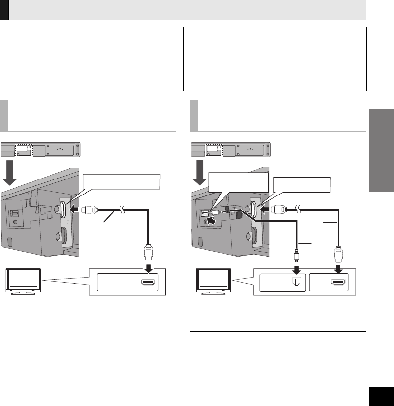
≥Turn off all equipment before connection and read the appropriate Owner’s Manuals.
Do not connect the AC power supply cord until all other connections are complete.
AHDMI cable (not supplied)
§Be sure to connect to the TV’s ARC compatible terminal.
(Refer to the Owner’s Manual for the TV.)
≥If the connected TV is ARC compatible, but audio is not
output to this unit, connect using the optical digital audio
cable. (>right, “B Not labeled “HDMI (ARC)””)
AHDMI cable (not supplied)
BOptical digital audio cable (not supplied)
≥Be sure to place the cable under the projecting part.
≥The optical digital audio cable connection is needed when
the HDMI cable is connected to a terminal that is not labeled
“HDMI (ARC)”.
Step 2 Connections
∫HDMI
The HDMI connection supports VIERA Link “HDAVI Control” (>20) when used with a compatible
Panasonic TV.
≥Use High Speed HDMI Cables that have the HDMI logo (as shown on the back cover). It is
recommended that you use Panasonic’s HDMI cable.
Recommended part number:
RP-CDHS15 (1.5 m/4.9 ft), RP-CDHS30 (3.0 m/ 9.8 ft), RP-CDHS50 (5.0 m/16.4 ft), etc.
≥Non-HDMI-compliant cables cannot be utilized.
Connection to a TV
∫Verify if the TV’s HDMI terminal is labeled
“HDMI (ARC)”.
The connection method will differ when the terminal
is labeled “HDMI (ARC)” and when it is not.
Labeled “HDMI (ARC)”: Method A
Not labeled “HDMI (ARC)”: Method B
∫What is ARC?
ARC is an abbreviation of Audio Return Channel, also known
as HDMI ARC. It refers to one of the HDMI functions. When
you connect the unit to the terminal labeled “HDMI (ARC)”, the
optical digital audio cable that is usually required in order to
listen to sound from a TV is no longer required, and TV pictures
and sound can be enjoyed with a single HDMI cable.
A Labeled
“HDMI (ARC)”
TVTV
HDMI AV OUT (ARC)
HDMI (ARC)
B Not labeled
“HDMI (ARC)”
TV
OPTICAL DIGITAL
AUDIO IN HDMI AV OUT
OPTICAL
OUT HDMI
SC-HTB520PP_RQTX1278-Y.book Page 15 Friday, February 11, 2011 11:25 AM
16
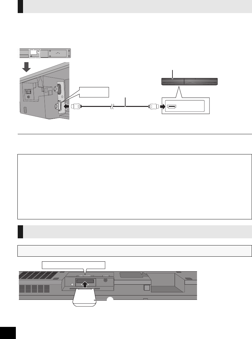
You can output the audio signal from the connected HDMI compatible Blu-ray player, DVD player, etc. with
this unit and pass the signal through to your TV.
Preparation
≥Connect this unit to the TV. (>15)
AE.g., Blu-ray Disc Player BHDMI cable (not supplied)
≥Refer to the Owner’s Manual of the connected HDMI compatible device for the necessary setting, to output the video and audio
signals.
ADigital transmitter (supplied)
Insert the digital transmitter, with the label facing down, until you hear a click.
Connection from an HDMI compatible device
HDMI AV IN
HDMI OUT
∫3D compatibility
Compatible with FULL HD 3D TV and Blu-ray Player
≥This unit can pass through the 3D signal from a 3D compatible Blu-ray Player to a FULL HD 3D TV.
∫x.v.ColorTM compatibility
You can enjoy vivid color of a wider color ranges for a more realistic picture when this unit is connected to a player and TV that
support x.v.ColorTM with an HDMI cable.
∫Deep Color compatibility
When this unit is connected to a compatible player, this unit can pass through the reproduced greater color gradation (4096 steps)
when connected to a compatible TV. You can enjoy exceptionally rich, natural-looking colors, with smooth, detailed gradation and
minimal color banding.
Digital transmitter connection
Do not insert or remove while this unit is on.
DIGITAL TRANSMITTER
SC-HTB520PP_RQTX1278-Y.book Page 16 Friday, February 11, 2011 11:25 AM
Getting started
17
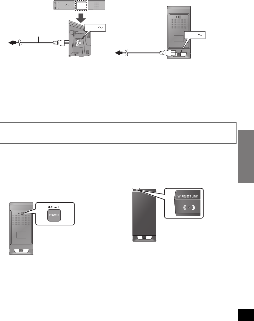
≥Connect only after all other connections are complete.
≥This system consumes a small amount of AC power, even when it is turned off (this unit; approx. 0.18 W,
the active subwoofer; approx. 0.07 W). In the interest of power conservation, if you will not be using this
system for a long time, unplug it from the household AC outlet.
≥The supplied AC power supply cord is for use with this unit and the active subwoofer only.
Do not use it with other equipment. Also, do not use cords for other equipment with this unit or the active
subwoofer.
1Turn on this unit.
2Press [B Í, C I POWER] on the
active subwoofer.
AUnit on/off button [B Í, C I POWER]
Use this button to turn the unit on and off.
C I:
The active subwoofer is on
B Í:
The active subwoofer is off
3Check that the wireless link is
activated.
BWIRELESS LINK indicator
The indicator lights when the active subwoofer is
turned on.
≥Red:
The active subwoofer is on and the wireless link
is deactivated
≥Green:
The active subwoofer is on and the wireless link
is activated
Step 3 AC power supply cord connection
Saving energy
This unit is designed to conserve its power consumption and save energy.
≥This unit will automatically turn to standby mode after 30 minutes if it is inactive.
Step 4 Active subwoofer wireless connection
AC IN
AC IN
AAC power supply cord (supplied)
≥Do not use any other AC power supply cord except the supplied one.
BTo a household AC outlet
SC-HTB520PP_RQTX1278-Y.book Page 17 Friday, February 11, 2011 11:25 AM
18
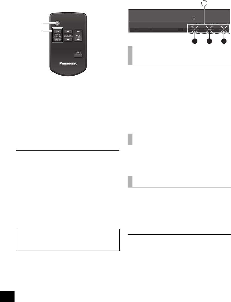
Using this unit
Preparation
≥Turn on the TV.
1Press [Í] to turn on this unit.
2Press [B Í, C I POWER] on the
active subwoofer to turn it on.
≥Make sure the wireless link indicator lights
green. (>17)
3Press [TV] or [BD/DVD] to select
the audio source. (>6)
≥If you have selected [BD/DVD], make sure to
select the TV’s input channel for this unit and
start the playback.
≥If there is sound coming out of the TV’s speakers, reduce the
volume of the TV to it’s minimum.
≥The maximum volume of the TV and this unit may be
different.
≥If this unit is turned off with the volume setting in the greater
half (above 50), this unit will automatically lower the volume
to the middle (50) when the unit is turned on. (Refer to page
22 to turn this function off.)
≥Even if this unit is turned off or the TV is selected as the input
source, this unit will continue to output audio or/and video
from the device connected to the HDMI AV IN terminal
through the HDMI AV OUT terminal.
≥The volume or the subwoofer level of this unit is not
displayed. The volume may be displayed on the TV if this unit
is connected to a Panasonic TV capable of displaying this
unit’s volume setting. (>20)
Press [iVOL j] to adjust the volume
of the speakers.
≥Volume range: 1 to 100
Press [iSUBWOOFER j] to adjust
the subwoofer level.
≥Subwoofer levels: 1 to 4
AThe indicators blink from left to right (i) or from
right to left (s).
≥The indicators will not blink when it has reached
the maximum or minimum.
Press [MUTE].
AThe indicators blink simultaneously while
muting.
≥To cancel, press the button again or adjust the volume.
≥Muting is canceled if this unit is turned off.
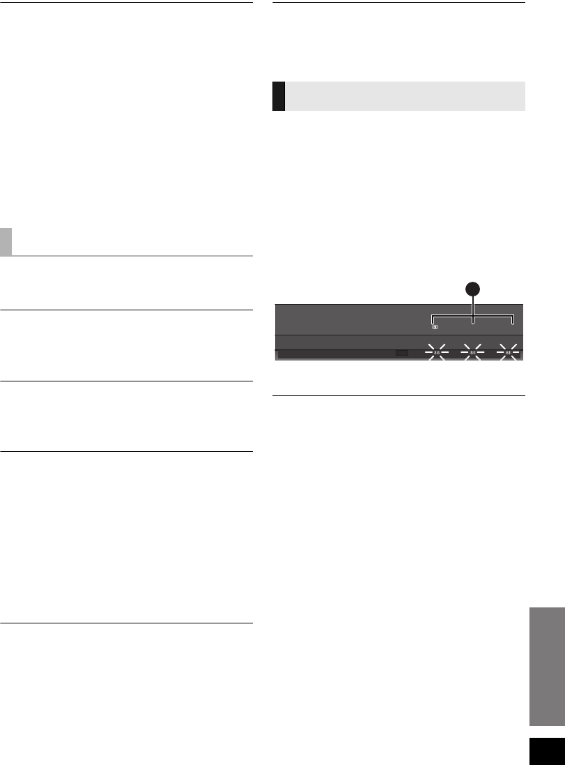
To display the current audio format,
Press the button for the current audio
source ([TV] or [BD/DVD]).
≥The current audio format is indicated for 4 sec.
ALights when Dolby Digital is the audio format
BLights when DTS is the audio format
CLights when PCM or LPCM is the audio format
≥The audio format status is also indicated for 4 sec if the audio
format on the selected source (TV, Blu-ray Disc/DVD Player,
etc.) is changed.
If this unit does not operate as
expected, return the settings to the
factory preset. (>21)
1
3
To adjust the volume/
subwoofer level
To mute the sound
Audio format indicator
TV BD/DVD DTS PCMD
A
A B C
SC-HTB520PP_RQTX1278-Y.book Page 18 Friday, February 11, 2011 11:25 AM
Operations
19
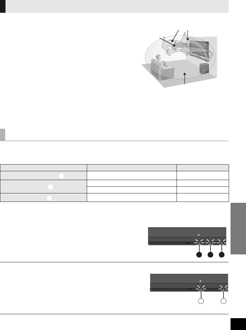
This unit provides a feeling that the sound and the image are as
one.
∫3D Surround
Even though there are no surround speakers, a surround effect
is obtained by the use of Dolby Virtual Speaker. Adding to this
effect, Panasonic has applied it’s own sound field controlling
technology to expand the sound field forwards, backwards,
upwards and downwards providing a sound with depth and
force that better matches 3D images.
∫Clear-mode Dialog
Sports commentary and dialogs from TV dramas are heard as if
the sound is coming from the TV, giving the feeling that the
sound and the image is as one.
Also, the dialog will stand out from the other sounds during
normal volume playback and when the volume is lowered for
night time viewing.
With this setting it is possible to choose between listening to the audio in 2 ch mode or with a surround
effect.
The surround effect can be added to 2 ch audio source as well as multi-channel sources.
§1 A surround effect is added when the audio source is multi-channel audio.
§2 The surround output mode indicator also blinks when the audio source is multi-channel during Auto Output Mode.
∫To change the playback mode
1 Press and hold [MUTE] for more than 2 sec.
≥The indicator for the current setting blinks for 10 sec.
2 While the indicator is blinking, press [MUTE] again to
change the setting.
≥The setting changes each time [MUTE] is pressed.
It is possible to turn off the 3D sound and only use the Dolby Virtual Speaker effect.
1 Press and hold [TV] for more than 2 sec.
≥The indicator for the current setting blinks for 10 sec.
A: 3D sound is “On”
B: 3D sound is “Off”
2 While the indicator is blinking press [TV] to change the setting.
≥The setting changes each time [TV] is pressed.
≥The setting will be reset to “On” when this unit is turned off.
≥When using the optical digital audio cable, the surround effect and Dolby Virtual Speaker will be automatically canceled if the
audio signal’s sampling frequency is greater than 48 kHz.
3D sound
Playback modes
Playback mode Audio source Surround effect
Surround output mode §12 ch/Multi-channel ±
Auto output mode §22ch s
Multi-channel ±
2 ch output mode 2 ch/Multi-channel s
1A clear dialog
2The sound and the image are as
one
3The feeling of being surrounded
by the sound field
E.g., Image of 3D sound
TV BD/DVD DTS PCM
D
BA C
TV BD/DVD DTS PCM
D
A B
SC-HTB520PP_RQTX1278-Y.book Page 19 Friday, March 4, 2011 9:20 AM

20
Linked operations with the TV
(VIERA LinkTM “HDAVI ControlTM”)
Preparation
1Confirm that the HDMI connection has been
made. (>15, 16)
2Set the “HDAVI Control” operations on the
connected equipment (e.g., TV).
3For the optimal “HDAVI Control” operations
change the following settings on the connected
TV§1.
≥Set the default speaker settings to this unit.§2
≥Set the speaker selection settings to this unit.
4Turn on all “HDAVI Control” compatible
equipment and select this unit’s input channel
on the connected TV so that the “HDAVI
Control” function works properly.
5If a device is connected to the HDMI AV IN
terminal, start play to check that the image is
displayed correctly.
When the connection or settings are changed,
repeat this procedure.
§1 The availability and function of the settings may vary
depending on the TV. Refer to the Owner’s Manual for the
TV for details.
§2 If the TV has a default speaker setting within the VIERA
Link setting items, choosing this unit as the default speaker
will automatically change the speaker selection to this unit.
≥VIERA Link “HDAVI Control”, based on the control functions
provided by HDMI which is an industry standard known as
HDMI CEC (Consumer Electronics Control), is a unique
function that we have developed and added. As such, its
operation with other manufacturers’ equipment that supports
HDMI CEC cannot be guaranteed.
≥This unit supports “HDAVI Control 5” function.
“HDAVI Control 5” is the newest standard (current as of
December, 2010) for Panasonic’s HDAVI Control compatible
equipment. This standard is compatible with Panasonic’s
conventional HDAVI equipment.
≥Please refer to individual manuals for other manufacturers’
equipment supporting VIERA Link function.
≥Be sure to set the digital audio output settings to be
compatible with this unit. (>23)
≥To make sure that the audio is output from this unit’s
speakers, select “Home theater” using the TV’s remote
control to turn this unit on.
≥The availability and function of the settings may vary
depending on the TV. Refer to the Owner’s Manual for the TV
for details.
∫Speaker control
You can select whether audio output is from this
unit or the TV speakers by using the TV menu
settings.
Home theater
This unit’s speakers are active.
≥When this unit is in standby mode, changing the TV speakers
to this unit in the TV menu will automatically turn this unit on
and select “TV” as the source.
≥You can control the volume setting using the Volume or Mute
button on the TV remote control.
≥If you turn off this unit, TV speakers will be automatically
activated.
TV
TV speakers are active.
≥The volume of this unit is set to its minimum.
≥If the TV is compatible to VIERA Link “HDAVI Control 4 or
later” the audio will automatically be output from this unit.
∫Automatic input switching
When the following operations are performed, this
unit will automatically turn on§ and change the input
channel to the corresponding source.
jWhen play starts on an HDMI connected device.
jWhen the input channel on the TV is changed.
§Only when speaker output is set to this unit.
≥If “Power off link” is activated on the TV, this unit will turn off
when the TV is turned off.
∫Automatic lip-sync function
(for HDAVI Control 3 or later)
Delay between audio and video is automatically
adjusted, enabling you to enjoy smooth audio for
the picture.
≥The delay information is automatically set if the TV is
compatible to VIERA Link “HDAVI Control 3 or later” and the
VIERA Link is set to “On”.
When the delay information cannot be retrieved, the audio
delay is set to 40 ms.
What is VIERA Link “HDAVI
Control”?
VIERA LinkTM is a new name for EZ SyncTM.
VIERA Link “HDAVI Control” is a convenient
function that offers linked operations of this
unit, and a Panasonic TV (VIERA) under
“HDAVI Control”.
You can use this function by connecting the
equipment with an HDMI cable. See the
Owner’s Manual for connected equipment for
operational details.
What you can do with
“HDAVI Control”
SC-HTB520PP_RQTX1278-Y.book Page 20 Friday, February 11, 2011 11:25 AM

Reference
Operations
21
Troubleshooting
Before requesting service, make the following
checks. If you are in doubt about some of the check
points, or if the solutions indicated in the following
guide do not solve the problem, refer to “Customer
Services Directory (United States and Puerto Rico)”
on page 26 if you reside in the U.S.A. or Puerto
Rico, or refer to “WARRANTY SERVICE” on
page 27 if you reside in Canada.
No power.
≥Insert the AC power supply cord securely. (>17)
≥After turning this unit on, if the indicators blink
and this unit immediately turns off, unplug the AC
power supply cord and consult your dealer.
The remote control does not work properly.
≥The battery is depleted. Replace it with a new
one. (>7)
≥It is possible that the insulation sheet has not
been removed. Remove the insulation sheet.
(>7)
≥It may be necessary to set the code of the remote
control again after changing the battery of the
remote control. (>23)
The “TV” indicator blinks, but there is no
sound.
Remove the AC power supply cord and consult
your dealer. If there are any other indicators
blinking, be sure to inform the blinking indicators to
your dealer.
The , DTS, PCM indicators blink for 10 sec
and then turn off.
≥Are you changing the playback mode settings?
(>19)
≥Are you changing the 3D sound settings? (>19)
≥Are you changing the audio output settings?
(>22)
The unit is automatically switched to standby
mode.
This unit will automatically turn to standby mode
after 30 minutes if it is inactive. (>17)
Power of this unit is turned off when the input
for the TV is changed.
This is a normal feature when using VIERA Link
(HDAVI Control 4 or later). For details please read
the Owner’s Manual for the TV.
This unit does not operate correctly.
If the HDMI cable is connected to the wrong
terminal (HDMI AV IN or HDMI AV OUT), this unit
will not operate correctly. Turn this unit off,
disconnect the AC power supply cord and
reconnect the HDMI cable(s). (>15, 16)
VIERA Link related operations no longer
function properly.
≥Check the “VIERA Link” setting on the connected
devices.
≥Have you turned the VIERA Link settings off?
≥When the HDMI connections are changed, after a
power failure or after the AC power supply cord
has been removed, VIERA Link operations may
not function properly.
jTurn on all the devices that are connected to
the TV with an HDMI cable and then turn the
TV on.
jTurn off the VIERA Link settings and turn it on
again. For details refer to the Owner’s Manual
for the TV.
jWhile this unit and the TV are connected with
the HDMI cable, turn on the TV and then
remove this unit’s AC powers supply cord and
reconnect it again.
The first few seconds of audio cannot be heard
when using the HDMI connection.
This may occur during DVD-Video chapter
playback. Change the digital audio output setting
on the connected device from “Bitstream” to “PCM”.
To return to the factory preset.
While this unit is on, press [POWER Í/I] on this
unit for more than 4 sec.
(All the indicators will blink twice when the unit is
reset.)
If this unit does not operate as expected,
return the settings to the factory preset.
General operation
D
HDMI
SC-HTB520PP_RQTX1278-Y.book Page 21 Friday, February 11, 2011 11:25 AM
22
If operations become unstable when connected to
a non-Panasonic HDMI compatible device, connect
using an optical digital audio cable. (
>
15)
Turn VIERA Link off.
1Press and hold [MUTE] on the remote control
and [VOLUME s] on this unit for more than 2
sec.
≥The setting is changed when the , DTS and
PCM indicators blink.
2After the setting has changed, turn off and then
on all the connected devices.
≥To reset the setting, return to the factory preset.
(>21)
≥When VIERA Link is turned off the ARC function
is not available. Be sure to connect the optical
digital audio cable. (>15)
No sound (or image).
≥Turn muting off. (>18)
≥Check the connections to the other devices.
(>15, 16)
≥Make sure that the received audio signal is
compatible with this unit. (>23)
≥Turn this unit off and then on again.
≥If this unit is connected to the TV with an HDMI
cable. Make sure that the TV’s HDMI terminal is
labeled “HDMI (ARC)”. If not, connect using the
optical digital audio cable. (>15)
≥If this unit is connected to a Panasonic TV and
this unit is turned on using the button on this unit
or the remote control, sound might not be output
from this unit’s speakers. In this case, turn this
unit on using the TV’s remote control. (>20)
≥If the connections are correct, there might be a
problem with the cables. Reconnect the unit with
different cables.
≥Check the audio output settings on the connected
device.
≥When the and DTS indicators blink and
there is no audio output from this unit, turn the
unit off, remove the AC power supply cord and
consult you dealer.
≥If the BD/DVD indicator flashes and there is no
audio output, try the following.
1Turn the connected device off and then on.
2Turn off this unit, remove the HDMI cable,
then reconnect the HDMI cable and turn this
unit back on.
DTS audio cannot be output from this unit.
Make sure that the digital audio output setting on
the connected device is set to “Bitstream”.
The audio output cannot be changed from main
to secondary.
If the digital output setting of TV or player is set to
“Bitstream” change the audio output on this unit.
1Press and hold [BD/DVD] for more than 2 sec.
2While the indicator of the current setting is
flashing, press [BD/DVD] to change the setting.
AMain and secondary
BMain
CSecondary (SAP: Secondary Audio Program)
≥The setting is maintained until it is changed
again.
The volume is lowered when the unit is turned
on.
If this unit is turned off with the volume setting in the
greater half (above 50), this unit will automatically
lower the volume to the middle (50) when the unit is
turned on.
To turn off this function:
1Press and hold [MUTE] on the remote control
and [VOLUME r] on this unit for more than 2
sec.
≥The setting is changed when the , DTS and
PCM indicators blink.
≥To reset the setting, return to the factory preset.
(>21)
The audio from the TV is distorted.
Change the TV’s digital audio output settings to
“Bitstream”.
The dialog is too persistent or the dialog does
not sound natural.
This unit has a function to make the dialog stand
out when the volume is low.
To turn off this function:
1Press and hold [TV] on the remote control and
[VOLUME s] on this unit for more than 2 sec.
≥The setting is changed when the , DTS and
PCM indicators blink.
≥To reset the setting, return to the factory preset.
(>21)
Sound
D
D
TV BD/DVD DTS PCMD
A
B C
D
D
SC-HTB520PP_RQTX1278-Y.book Page 22 Friday, February 11, 2011 11:25 AM
Reference
23
There is no audio.
The power of the unit turns off automatically.
(When this unit detects a problem, a safety
measure is activated and this unit automatically
switches to standby mode.)
≥There is a problem with the amplifier.
≥Is the volume extremely high?
If so, lower the volume.
≥Is this unit placed in an extremely hot place?
If so, move the unit to a cooler place and wait a
few moments and then try to turn it on again.
If the problem persists, turn the unit off and remove
the AC power supply cord and consult your dealer.
Please be sure to remember the indicators that
were blinking and inform the dealer.
No power.
Ensure the AC power supply cord of the active
subwoofer is connected properly.
After turning the subwoofer on, it immediately
turns off.
Unplug the AC power supply cord and consult your
dealer.
No sound from the subwoofer.
≥Check that the active subwoofer is turned on.
≥Check that the wireless link indicator lights green.
(>17)
The wireless link indicator lights red.
≥There is no link between this unit and the active
subwoofer.
jCheck that this unit is turned on.
jEnsure that the digital transmitter is fully inserted
into the digital transmitter dock on this unit.
(>16)
jTurn the active subwoofer off and then back on.
Alternatively, turn the active subwoofer off,
disconnect the AC power supply cord and then
reconnect it.
≥Consult your dealer if the problem persists.
The audio from the subwoofer is interrupted.
The active subwoofer is automatically seeking a
clear channel. If the interference persists, try
moving the other wireless devices to another
location outside the range of the active subwoofer
or move the active subwoofer nearer to this unit.
(>9)
The wireless link indicator lights red and green
alternately.
Turn the subwoofer off, disconnect the AC supply
cord and then reconnect it.
Consult your dealer if the problem persists.
When other Panasonic products respond to this
unit’s remote control, change the remote control
code on this unit and the remote control.
Preparation
≥Turn off all other Panasonic products.
≥Turn on this unit.
Change the remote control to code 2:
1Aim the remote control at this unit’s remote
control sensor.
2Press and hold [MUTE] and [BD/DVD] on the
remote control for more than 4 sec.
A will blink for 10 sec when the code of this unit is
changed.
≥If the unit does not operate after changing the code, repeat
steps 1 and 2.
≥To change the remote control to code 1, repeat the steps
above, but replace [BD/DVD] with [TV].
Audio information
∫Compatible audio formats
This unit is compatible with the following formats:
Dolby Digital, DTS Digital Surround, 2-channel
LPCM and multi-channel LPCM.
Active Subwoofer
Remote control code
TV BD/DVD DTS PCMD
A
SC-HTB520PP_RQTX1278-Y.book Page 23 Friday, February 11, 2011 11:25 AM

24
Specifications
1 Specifications are subject to change without notice.
Mass and dimensions are approximate.
2 Total harmonic distortion is measured by a digital spectrum
analyzer.
GENERAL
Power consumption: This unit: 25 W
Active Subwoofer: 21 W
Digital transmitter: 1.2 W
Power consumption in standby mode:
This unit: Approx. 0.18 W
Active Subwoofer: Approx. 0.07 W
Power supply: AC 120 V, 60 Hz
Dimensions (WkHkD):
This unit
(Excluding projecting parts)
1018 mmk75 mmk44 mm
(3911/16qk215/16qk123/32q)
(With safety holder)
1018 mmk77 mmk52 mm
(3911/16qk31/32qk21/16q)
(With stands (Low))
1018 mmk95 mmk75 mm
(3911/16qk33/4qk215/16q)
(With stands (High))
1018 mmk105 mmk75 mm
(3911/16qk41/8qk215/16q)
Active Subwoofer
180 mmk408 mmk306 mm
(73/32qk161/16qk121/16q)
Digital transmitter
43.5 mmk37.3 mmk8.2 mm
(123/32qk115/32qk5/16q)
Mass (Weight):
This unit
(Without accessories)
Approx. 2.5 kg(5.5 lbs)
(With safety holder)
Approx. 2.6 kg(5.7 lbs)
(With stands)
Approx. 2.6 kg(5.7 lbs)
Active Subwoofer
Approx. 5.2 kg(11.5 lbs)
Digital transmitter
Approx. 0.0095 kg(0.0209 lbs)
Operating temperature range:
0oC to r40 oC (r32 oF to r104 oF)
Operating humidity range:
20 % to 80 % RH (no condensation)
SPEAKER SECTION
FRONT SPEAKERS (BUILT-IN)
Type: 2 way, 2 speaker system (Bass Reflex)
Woofer: 6.5 cm (21/2q) Cone typek2
Tweeter: 2.5 cm (1q) Semi-dome typek2
ACTIVE SUBWOOFER
Type: 1 way, 1 speaker system (Bass Reflex)
Woofer: 16 cm (61/2q) Cone type
Frequency range: 30 Hz to 180 Hz (s16 dB)
35 Hz to 160 Hz (s10 dB)
AMPLIFIER SECTION
RMS Output Power: Dolby Digital Mode
Front ch: 60 W per channel (4 ≠),
1kHz, 10% THD
Subwoofer ch: 120 W per channel (8 ≠),
100 Hz, 10 % THD
Total RMS Dolby Digital mode power: 240 W
FTC Output Power: Dolby Digital Mode
Front ch: 25 W per channel (4 ≠),
140Hzto20kHz,1%THD
Subwoofer ch: 37 W per channel (8 ≠),
40Hzto150Hz,1%THD
Total FTC Dolby Digital mode power: 87 W
WIRELESS SECTION
Wireless module
Frequency Range: 2.4 GHz to 2.4835 GHz
Number of channels: 3
TERMINAL SECTION
HDAVI Control
This unit supports “HDAVI Control 5” function.
HDMI AV input
Terminal: 19-pin type A connector
HDMI AV output
Terminal: 19-pin type A connector
Digital audio input (TV only)
Optical digital input: Optical terminal
Sampling frequency: 32 kHz, 44.1 kHz, 48 kHz
Audio Format: LPCM, Dolby Digital,
DTS Digital Surround
IR Blaster
Terminal Type: 3.5 mm (1/8q)jack
SC-HTB520PP_RQTX1278-Y.book Page 24 Friday, February 11, 2011 11:25 AM

Reference
25
Limited Warranty
(ONLY FOR U.S.A. AND PUERTO RICO)
Panasonic Consumer Electronics Company,
Division of Panasonic Corporation of North America
One Panasonic Way, Secaucus, New Jersey 07094
Panasonic Home Audio Products Limited Warranty
Limited Warranty Coverage
(For USA and Puerto Rico Only)
If your product does not work properly because of a defect in
materials or workmanship, Panasonic Consumer Electronics
Company (referred to as “the warrantor”) will, for the length of
the period indicated on the chart below, which starts with the
date of original purchase (“warranty period”), at its option either
(a) repair your product with new or refurbished parts, (b)
replace it with a new or a refurbished equivalent value product,
or (c) refund your purchase price. The decision to repair,
replace or refund will be made by the warrantor.
During the “Labor” warranty period there will be no charge for
labor. During the “Parts” warranty period, there will be no
charge for parts. This Limited Warranty excludes both parts and
labor for non-rechargeable batteries, antennas, and cosmetic
parts (cabinet). This warranty only applies to products
purchased and serviced in the United States or Puerto Rico.
This warranty is extended only to the original purchaser of a
new product which was not sold “as is”.
Carry-In or Mail-In Service
To find a service center please visit http://www.panasonic.com/
help or call 1-800-211-PANA (7262).
When shipping the unit, carefully pack, include all accessories,
and send it prepaid, adequately insured and preferably in the
original carton. When shipping Lithium Ion batteries please visit
our Web Site at www.panasonic.com/BatteryHandling as
Panasonic is committed to providing the most up to date
information. Include a letter detailing the complaint, a return
address and provide a daytime phone number where you can
be reached. A valid registered receipt is required under the
Limited Warranty.
IF REPAIR IS NEEDED DURING THE WARRANTY
PERIOD, THE PURCHASER WILL BE REQUIRED TO
FURNISH A SALES RECEIPT/PROOF OF PURCHASE
INDICATING DATE OF PURCHASE, AMOUNT PAID
AND PLACE OF PURCHASE. CUSTOMER WILL BE
CHARGED FOR THE REPAIR OF ANY UNIT RECEIVED
WITHOUT SUCH PROOF OF PURCHASE.
Limited Warranty Limits And Exclusions
This warranty ONLY COVERS failures due to defects in
materials or workmanship, and DOES NOT COVER normal
wear and tear or cosmetic damage. The warranty ALSO DOES
NOT COVER damages which occurred in shipment, or failures
which are caused by products not supplied by the warrantor, or
failures which result from accidents, misuse, abuse, neglect,
mishandling, misapplication, alteration, faulty installation,
set-up adjustments, misadjustment of consumer controls,
improper maintenance, power line surge, lightning damage,
modification, introduction of sand, humidity or liquids,
commercial use such as hotel, office, restaurant, or other
business or rental use of the product, or service by anyone
other than a Factory Service Center or other Authorized
Servicer, or damage that is attributable to acts of God.
THERE ARE NO EXPRESS WARRANTIES EXCEPT AS
LISTED UNDER “LIMITED WARRANTY COVERAGE”.
THE WARRANTOR IS NOT LIABLE FOR INCIDENTAL
OR CONSEQUENTIAL DAMAGES RESULTING FROM
THE USE OF THIS PRODUCT, OR ARISING OUT OF
ANY BREACH OF THIS WARRANTY.
(As examples, this excludes damages for lost time, travel to
and from the servicer, loss of or damage to media or images,
data or other memory or recorded content. The items listed are
not exclusive, but for illustration only.)
ALL EXPRESS AND IMPLIED WARRANTIES,
INCLUDING THE WARRANTY OF MERCHANTABILITY,
ARE LIMITED TO THE PERIOD OF THE LIMITED
WARRANTY.
Some states do not allow the exclusion or limitation of incidental
or consequential damages, or limitations on how long an
implied warranty lasts, so the exclusions may not apply to you.
This warranty gives you specific legal rights and you may also
have other rights which vary from state to state. If a problem
with this product develops during or after the warranty period,
you may contact your dealer or Service Center. If the problem is
not handled to your satisfaction, then write to the warrantor’s
Consumer Affairs Department at the addresses listed for the
warrantor.
PARTS AND SERVICE, WHICH ARE NOT COVERED BY
THIS LIMITED WARRANTY, ARE YOUR
RESPONSIBILITY.
Product or Part Name Parts Labor
Audio Products
(except items below)
1 year 1 year
DVD Home Theater System 1 year 1 year
Home Theater Audio System 1 year 1 year
USB Reader-writer, PC Card
Adapters (defective
exchange)
1 year Not Applicable
Accessories: Headphones,
cartridges, Microphones,
Adapters
90 days 90 days
Rechargeable Batteries,
DVD-RAM Disc (defective
exchange)
10 days Not
Applicable
SD Memory Cards,
Rechargeable Battery Packs
(defective exchange)
90 days Not
Applicable
SC-HTB520PP_RQTX1278-Y.book Page 25 Friday, February 11, 2011 11:25 AM

26
As of December 2010
Customer Services Directory (United States and Puerto Rico)
Obtain Product Information and Operating Assistance; locate your nearest Dealer or Service
Center; purchase Parts and Accessories; or make Customer Service and Literature requests by
visiting our Web Site at:
http://www.panasonic.com/help
or, contact us via the web at:
http://www.panasonic.com/contactinfo
You may also contact us directly at:
1-800-211-PANA (7262)
Monday-Friday 9am-9pm,
Saturday-Sunday 10am-7pm EST
For hearing or speech impaired TTY users, TTY: 1-877-833-8855
Accessory Purchases (United States and Puerto Rico)
Purchase Parts, Accessories and Instruction Books online for all Panasonic Products by visiting our Web
Site at:
http://www.pstc.panasonic.com
Or, send your request by E-mail to:
npcparts@us.panasonic.com
You may also contact us directly at:
1-800-332-5368 (Phone) 1-800-237-9080 (Fax Only)
(Monday-Friday 9am-9pm EST)
Panasonic Service and Technology Company
20421 84th Avenue South, Kent, WA 98032
(We accept Visa, MasterCard, Discover Card, American Express, and Personal Checks)
For hearing or speech impaired TTY users, TTY: 1-866-605-1277
SC-HTB520PP_RQTX1278-Y.book Page 26 Friday, February 11, 2011 11:25 AM

Reference
27
Limited Warranty (
ONLY FOR
CANADA)
Panasonic Canada Inc.
5770 Ambler Drive, Mississauga, Ontario L4W 2T3
PANASONIC PRODUCT - LIMITED WARRANTY
Panasonic Canada Inc. warrants this product to be free from defects in material and workmanship under normal use and
for a period as stated below from the date of original purchase agrees to, at its option either (a) repair your product with
new or refurbished parts, (b) replace it with a new or a refurbished equivalent value product, or (c) refund your purchase
price. The decision to repair, replace or refund will be made by Panasonic Canada Inc.
Technics Audio Product - One (1) year, parts and labour
Panasonic BD/DVD Product - One (1) year, parts and labour
Panasonic Audio Receivers - One (1) year, parts and labour
Home Theater Systems Product - One (1) year, parts and labour
This warranty is given only to the original purchaser, or the person for whom it was purchased as a gift, of a Panasonic
brand product mentioned above sold by an authorized Panasonic dealer in Canada and purchased and used in Canada,
which product was not sold “as is”, and which product was delivered to you in new condition in the original packaging.
IN ORDER TO BE ELIGIBLE TO RECEIVE WARRANTY SERVICE HEREUNDER, A PURCHASE RECEIPT OR OTHER
PROOF OF DATE OF ORIGINAL PURCHASE, SHOWING AMOUNT PAID AND PLACE OF PURCHASE IS REQUIRED
LIMITATIONS AND EXCLUSIONS
This warranty ONLY COVERS failures due to defects in materials or workmanship, and DOES NOT COVER normal wear
and tear or cosmetic damage. The warranty ALSO DOES NOT COVER damages which occurred in shipment, or failures
which are caused by products not supplied by Panasonic Canada Inc., or failures which result from accidents, misuse,
abuse, neglect, mishandling, misapplication, alteration, faulty installation, set-up adjustments, misadjustment of consumer
controls, improper maintenance, power line surge, lightning damage, modification, introduction of sand, humidity or liquids,
commercial use such as hotel, office, restaurant, or other business or rental use of the product, or service by anyone other
than an Authorized Servicer, or damage that is attributable to acts of God.
Dry cell batteries are also excluded from coverage under this warranty.
THIS EXPRESS, LIMITED WARRANTY IS IN LIEU OF ALL OTHER WARRANTIES, EXPRESS OR IMPLIED,
INCLUDING ANY IMPLIED WARRANTIES OF MERCHANTABILITY AND FITNESS FOR A PARTICULAR PURPOSE. IN
NO EVENT WILL PANASONIC CANADA INC. BE LIABLE FOR ANY SPECIAL, INDIRECT OR CONSEQUENTIAL
DAMAGES RESULTING FROM THE USE OF THIS PRODUCT OR ARISING OUT OF ANY BREACH OF ANY EXPRESS
OR IMPLIED WARRANTY. (As examples, this warranty excludes damages for lost time, travel to and from the Authorized
Servicer, loss of or damage to media or images, data or other memory or recorded content. This list of items is not
exhaustive, but for illustration only.)
In certain instances, some jurisdictions do not allow the exclusion or limitation of incidental or consequential damages, or
the exclusion of implied warranties, so the above limitations and exclusions may not be applicable. This warranty gives you
specific legal rights and you may have other rights which vary depending on your province or territory.
WARRANTY SERVICE
For product operation and information assistance, please contact:
PRODUCT OPERATION ASSISTANCE
Customer Care Centre: Telephone #: 1-800-561-5505
Fax #: (905) 238-2360
Email link: “Support # contact us # email” on www.panasonic.ca
PRODUCT REPAIRS
Please locate your nearest Authorized Servicentre.
Link: “Support # Panasonic Servicentre® locator” on www.panasonic.ca
IF YOU SHIP THE PRODUCT TO A SERVICENTRE
Carefully pack and send prepaid, adequately insured and preferably in the original carton.
Include details of the defect claimed, and proof of date of original purchase.
SC-HTB520PP_RQTX1278-Y.book Page 27 Friday, February 11, 2011 11:25 AM

Panasonic Corporation 2011
Printed in Singapore
One Panasonic Way, Secaucus,
New Jersey 07094
http://www.panasonic.com
www.panasonic.ca
5770 Ambler Drive
Mississauga, Ontario
L4W 2T3
[For\U.S.A.\and\Puerto\Rico] \For\Canada\
RQTX1278-2Y
F0211ZU2031
THE FOLLOWING APPLIES ONLY IN THE U.S.A.
FCC Note:
This equipment has been tested and found to comply with the limits for a Class B digital device, pursuant to Part 15 of the FCC Rules.
These limits are designed to provide reasonable protection against harmful interference in a residential installation. This equipment
generates, uses, and can radiate radio frequency energy and, if not installed and used in accordance with the instructions, may cause
harmful interference to radio communications.
However, there is no guarantee that interference will not occur in a particular installation. If this equipment does cause harmful
interference to radio or television reception, which can be determined by turning the equipment off and on, the user is encouraged to
try to correct the interference by one or more of the following measures:
≥Reorient or relocate the receiving antenna.
≥Increase the separation between the equipment and receiver.
≥Connect the equipment into an outlet on a circuit different from that to which the receiver is connected.
≥Consult the dealer or an experienced radio/TV technician for help.
FCC caution: To maintain compliance with FCC regulations, shielded interface cables must be used with this equipment. Operation
with non-approved equipment or unshielded cables may result in interference to radio and TV reception. Any changes or
modifications not approved by the party responsible for compliance could void the user’s authority to operate this equipment.
This device complies with Part 15 of the FCC Rules.
Operation is subject to the following two conditions:
(1) This device may not cause harmful interference, and
(2) this device must accept any interference received, including interference that may cause undesired operation.
Responsible Party:
Panasonic Corporation of North America
One Panasonic Way
Secaucus, NJ 07094
Support Contact:
Panasonic Consumer Electronics Company
Telephone No.: 1-800-211-PANA (7262)
WARNING:
To satisfy FCC RF exposure requirements for mobile transmitting devices, a separation distance of 20 cm (77/8q) or more should be
maintained between the antenna of this device and persons during device operation. To ensure compliance, operations at closer than
this distance is not recommended. The antenna used for this transmitter must not be co-located in conjunction with any other antenna
or transmitter.
As an ENERGY STAR Partner,
Panasonic has determined that
this product meets the ENERGY STAR
guidelines for energy efficiency.
®
®
For Canada only: The word “Participant” is
used in place of the word “Partner”.
SC-HTB520PP_RQTX1278-Y.book Page 28 Friday, March 4, 2011 9:20 AM
