Panasonic TY ST42PF3 Installation Guide_1 User Manual To The Ed27d1d2 F282 44cc 9915 A2936cb524d4
User Manual: Panasonic TY-ST42PF3 to the manual
Open the PDF directly: View PDF ![]() .
.
Page Count: 59

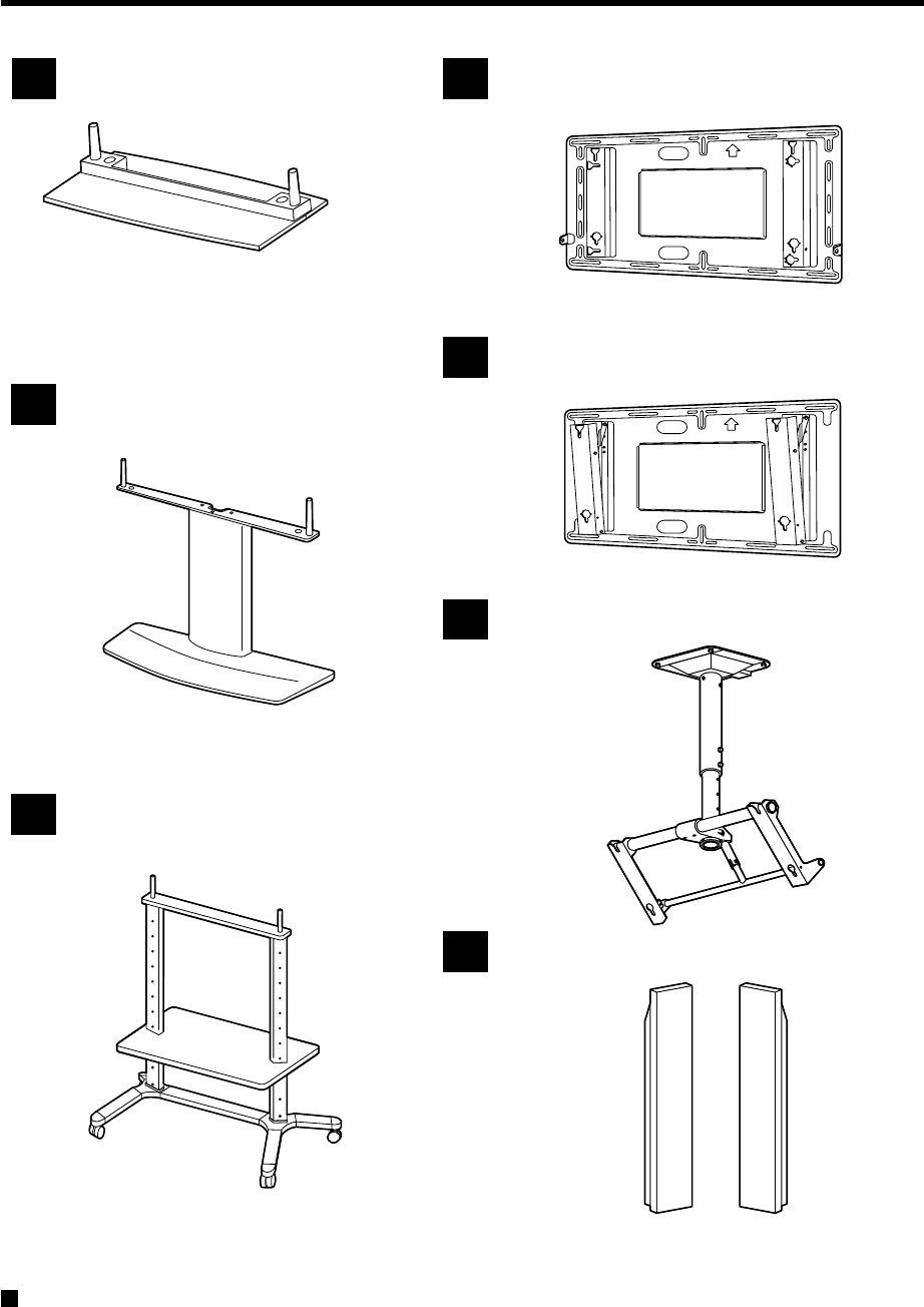
Pedestal
TY-ST42PT3S TY-ST42PT3K
Wall stand
TY-ST42PW1
Mobile stand
TY-ST42PF3
Wall-hanging bracket (vertical)
TY-WK42PV1
Wall-hanging bracket (angled)
TY-WK42PR1
Ceiling unit
TY-CE42PS1
Speakers
TY-SP42PM3W TY-SP42PWD3W

How to use this manual
Some notes on how to read this manual
In this manual, the number such as "1, 2, 3,..." appears to the left of each step.
Go ahead in numerical order.
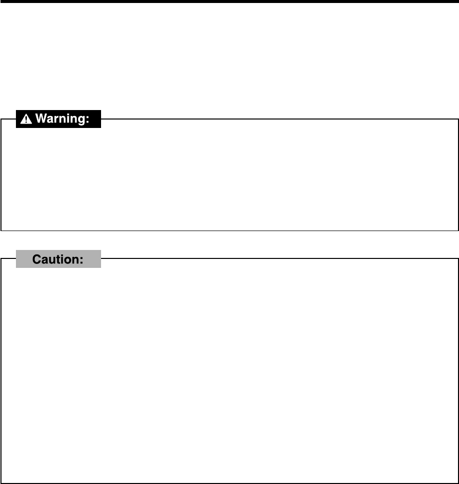
Indicates a situation where incorrect handling may result in death or serious injury for the person performing the
installation.
Indicates a situation where incorrect handling may result in breakdown or damage to physical objects.
Contains more detailed information than in the steps in the main text. Be sure to read the notes.
Other notes
• More-detailed explanations and supplemental information for the installation procedures are given on the right.
* Be sure to read not just the steps on the left, but the information on the right as well.
• At the very beginning of the installation procedure, there are illustrations for assembling various accessory parts
on the Wide Plasma Display. Refer to them when installing.
• Each installation procedure for accessory parts is preceded by a brief description of the procedure. During the
pro-cedure, refer to the description if necessary.
• Each installation procedure for accessory parts is followed by an explanation of how to remove the Wide Plasma
Display. Refer to this when it is necessary to remove the accessory parts from the Wide Plasma Display and reposition
it.
Before installing
Be sure to read through these instructions before starting the installation.
The installation should be only performed by a professional person.
If any parts are not installed correctly, the display unit may fall, possibly resulting in damage and personal injury.
Failure to follow Warning instructions may result in damage and personal injury.
Make sure that all safety conditions regarding strength at installation are observed.
If the installation strength is insufficient, the display unit may fall and personal injury may result.
Do not install in places which are unable to bear the weight of the display.
If the strength of the floor and wall at the site of installation is insufficient, the display unit may fall, possibly
resulting in damage and personal injury.
A caution indicates special precautions against actions which may result in fire or electric shock.
Do not install in places subject to humidity, dust, oil fumes, condensation or excessive heat.
These factors may adversely affect the Wide Plasma Display, possibly resulting in fire or electric shock.
Do not install the Wide Plasma Display horizontally with the screen facing up, or sideways or upside
down.
Installing the screen other than in the conventional viewing setting may cause heat to build up inside the display
and possibly result in fire.
Two persons are required to install and remove the display unit.
The display unit is heavy and at least two persons are needed to handle it safely. The display unit may drop and
personal injury may result if one person attempts to install it without assistance.
Maintain a space of at least 10 cm respectively at the top, bottom and sides of the display unit and at
least 1.9 cm at the rear of the display unit.
The display unit has air outlet holes at the top and air intake holes at the bottom and rear. These holes must not
be blocked, nor airflow not be obstructed. Otherwise fire may result.
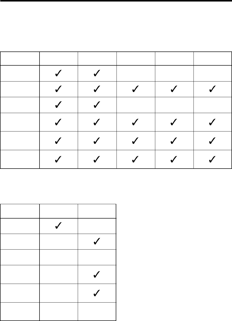
Tools list
The tools in the following tables are necessary for complete assembly.
Before attempting to install the accessories, make sure you have the following tools on hand.
Optional parts list
Pedestal
Wall stand
Mobile stand
Wall-hanging
bracket (vertical)
Wall-hanging
bracket (angled)
Ceiling unit
–––
–––
Plus screw driver Clean cloth Drill Measure Level gauge
–
–
–
–
–
–
Pedestal
Wall stand
Mobile stand
Wall-hanging
bracket (vertical)
Wall-hanging
bracket (angled)
Ceiling unit
Wire or Chain M6 bolt x 6
Accessory list
TY-ST42PT3-S
TY-ST42PT3-K
TY-ST42PW1
Pedestal Wall-hanging bracket (vertical)
Wall-hanging bracket (angled)
Wall stand
1
2
4
5
TY-WK42PR1
TY-WK42PV1
TY-ST42PF3
Mobile stand
3
TY-CE42PS1
Ceiling unit
6
TY-SP42PM3W
TY-SP42PWD3W
Speakers
7
For information on the wiring of the Wide Plasma Display after installing accessories, be sure to refer to the
documentation that comes with the Wide Plasma Display.
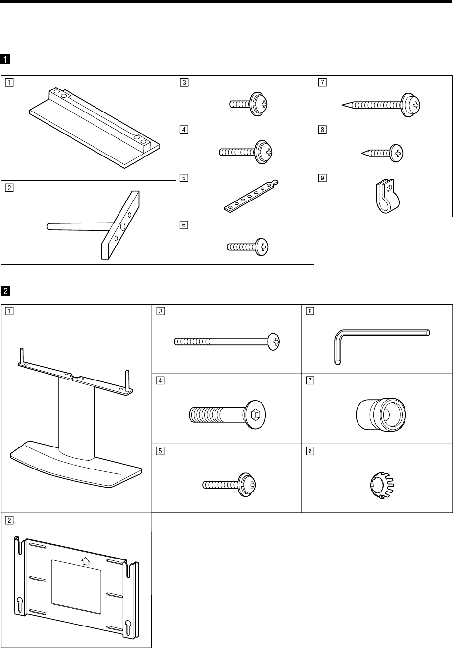
Parts list
Check the part number before performing the installation procedure.
Base Assembly screw(M5-20) x 4
Assembly screw (M5-30) x 4
Pedestal
Wall pedestal
Holding bracket
Allen key (accessory) Fixing screw (M5) x 2
Pan head bolt with hex socket
(M8-45) x 4
Insulating spacer x 4
Toothed pan washer x 4 Fixing screw (M5) x 2 Assembly
Wall stand
Pole x 2
Wood screw x 2
Black screw x 2
Band x 2
Black screw x 2
Clamp x 4
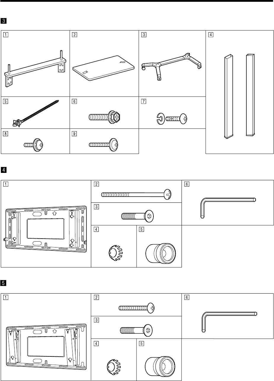
Wall-hanging bracket unit Fixing screw (M5) x 2
Pan head bolt with hex socket (M8-45) x 4
Tooted pan
washer x 4
Insulating
spacer x 4
Wall-hanging bracket unit Fixing screw (M5-35) x 2
Pan head bolt with hex socket (M8-45) x 4
Tooted pan
washer x 4
Insulating
spacer x 4
Allen key (accessory)
Allen key (accessory)
Wall-hanging bracket ( vertical )
Wall-hanging bracket ( angled )
Holder Shelf Stand base Support x 2
Cable strap x 5 Bolt (M8)x 4
Assembly screw (M6-16)
and spring washer x 4 each
Assembly screw (M5-15) x 4
Assembly screw (M5-30) x 4
Mobile stand
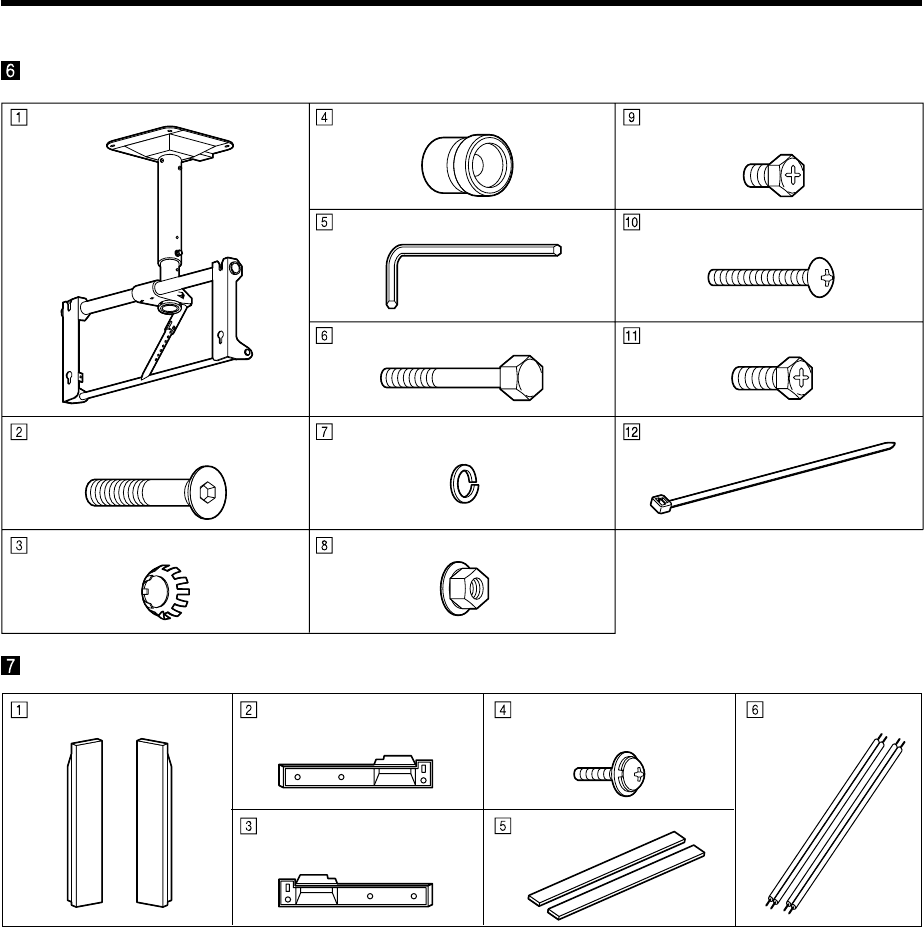
Ceiling unit Fixing bolt (M8-12) x 2
Ceiling unit
Allen key
Fixing bolt (M8-100)
Spring washer
Washer pan nut (M8)
Fixing screw (M5) x 2
Fixing bolt (M8-20) x 2
Cable tie x 2 Pan head bolt with hex socket
(M8-45) x 4
Toothed pan washer
x 4
Insulating spacer
x 4
Points to note during installation
•This ceiling unit is for mounting a Wide Plasma Display to a ceiling for viewing purposes.
Do not use it for any type of installation other than ceiling mounting.
• In order to ensure correct, problem-free operation of the Wide Plasma Display, do not install the Display in any of
the following places:
• Next to sprinklers or sensors
• Where it may be subject to vibration or shocks
• Near high-voltage wires or electric motors
• Where it may be in direct contact with air from heaters
• When installing this ceiling unit, use a fixing method appropriate to the type of ceiling.
• Insert the mains plug for the Wide Plasma Display into a mains socket which is close and easily accessible.
• Provide adequate ventilation so that the temperature around the display does not rise above 40°C (104 F°).
If there is insufficient movement of the air inside the display, heat may build up inside the display and fire may result.
• For U.S.A (TH-42PW3 / TH-42PWD3 only)
If the connection cable cannot reach the Display when it has been installed to the wall, use the 15 m cable (TY-
SCP15C03) which is sold separately.
Speakers
Speaker x 2
Bracket mounting
Assembly screw (M4-10) x 12
Mounting bracket
(right) x 2
Mounting bracket
(left) x 2
Sponge x 2
Speaker cable
(20 cm) x 2
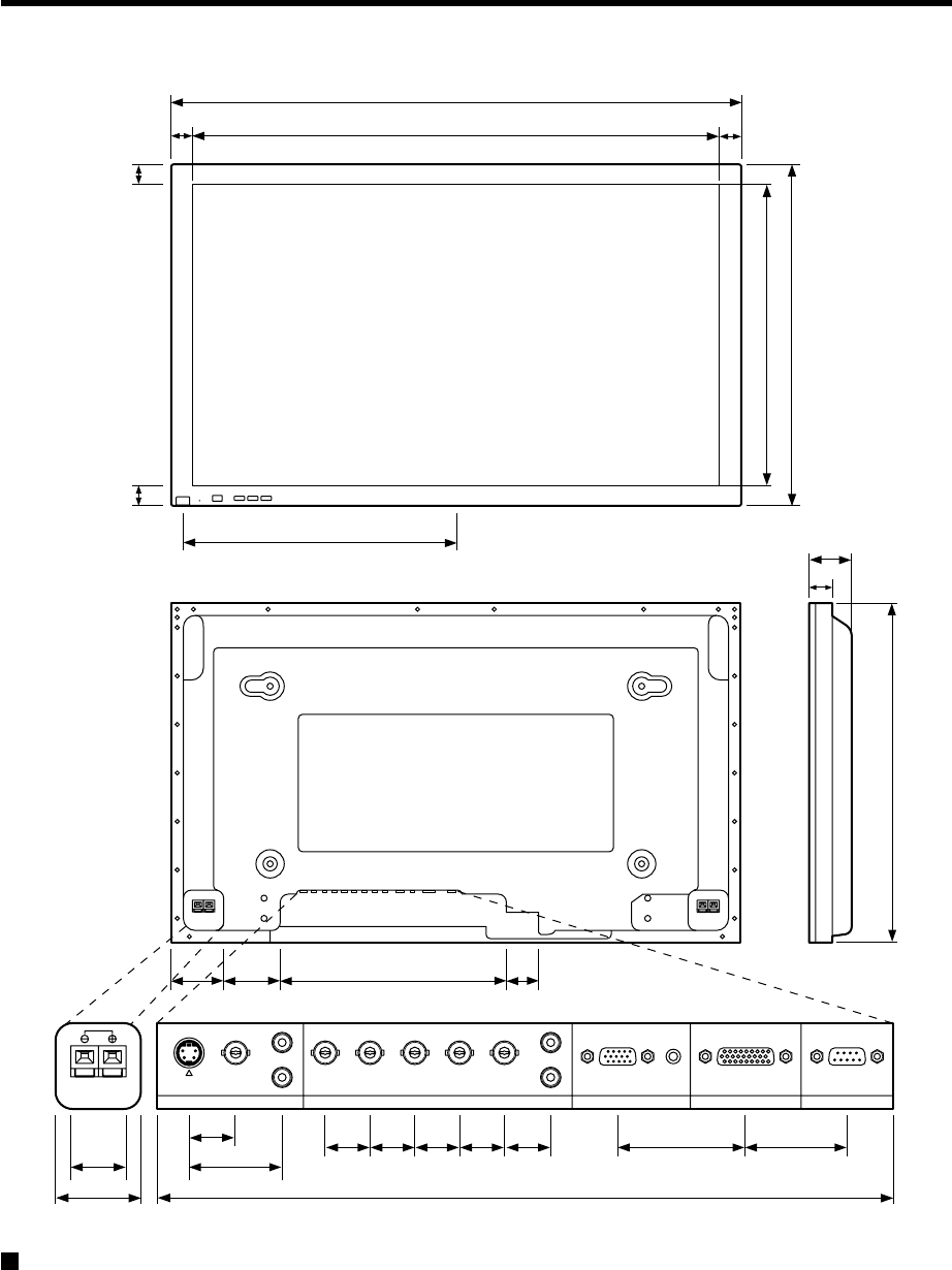
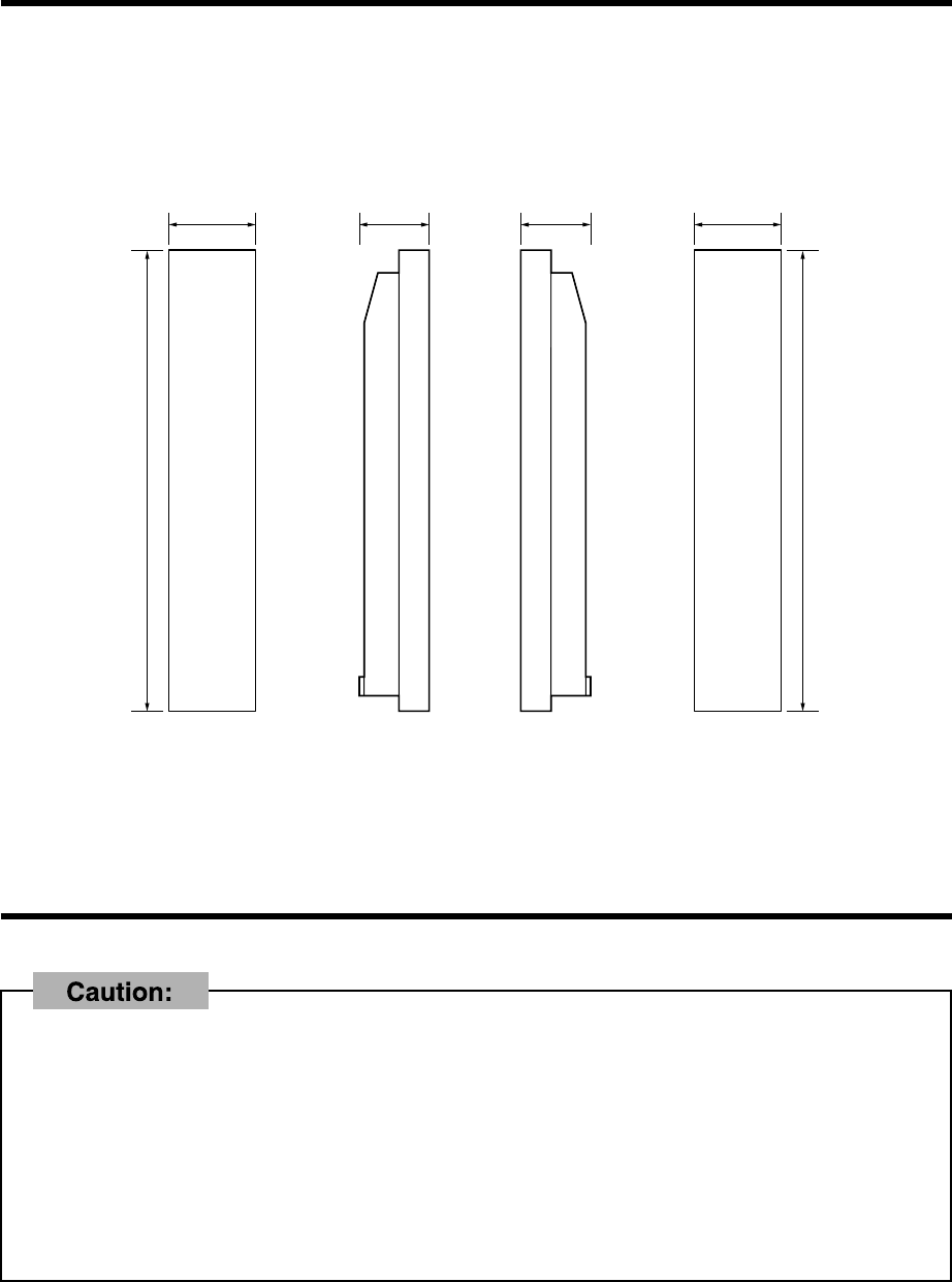
Dimensions of the display unit
S-VIDEO
VIDEO VD HD PR/CR/R PB/CB/B Y/G
L
R
L
R
AUDIO AUDIO
AUDIO
SERIALTUNER IN
PC INCOMPONENT/RGB IN
AV IN
1020
920
50
610
518
615
89
50
22
18.5
35.7
70.69 296
18 18 18 18 20 53.86
98
39.43
4646
489
44
112.2 65390.9
Units : mm
To connect the power cord and others, refer to the documentation that comes with the Wide Plasma Display.
1-1
Pedestal
TY-ST42PT3S
TY-ST42PT3K
Assembly diagram
CONTENTS
Instruction of the installation ...................... 1-2
1.Assembling the pedestal.................................... 1-2
2.Attaching the pedestal to the display unit .............. 1-2
3.Fixing the display unit ....................................... 1-3
1-2
Instruction of the installation
Assembling the pedestal
Attaching the pedestal to the display unit
Ensure that the poles sit
flush with the bottom of
the base.
Place the display face
down on a cloth clean
and free from other
foregin particles, and
then proceed to the next
step.
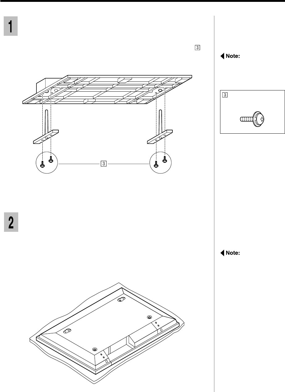
Spread a clean cloth over a level floor or base, and place on it the display
unit face down.
Remove the screws and covers.
Keep them in a safe place for possible future use.
1
Put the poles into the outer holes on the base, and fasten the four
screws.
1
Assembly screw
(M5-20) x 4
1-3
Insert the four screws, two on each side, into the holes in the back
of the display unit and screw them into the holes on the inserted poles.
3
Front
Rear
Fixing the display unit
Insert the two poles at the top of the pedestal into the holes in the base
of the display unit as shown in the illustration below.
2
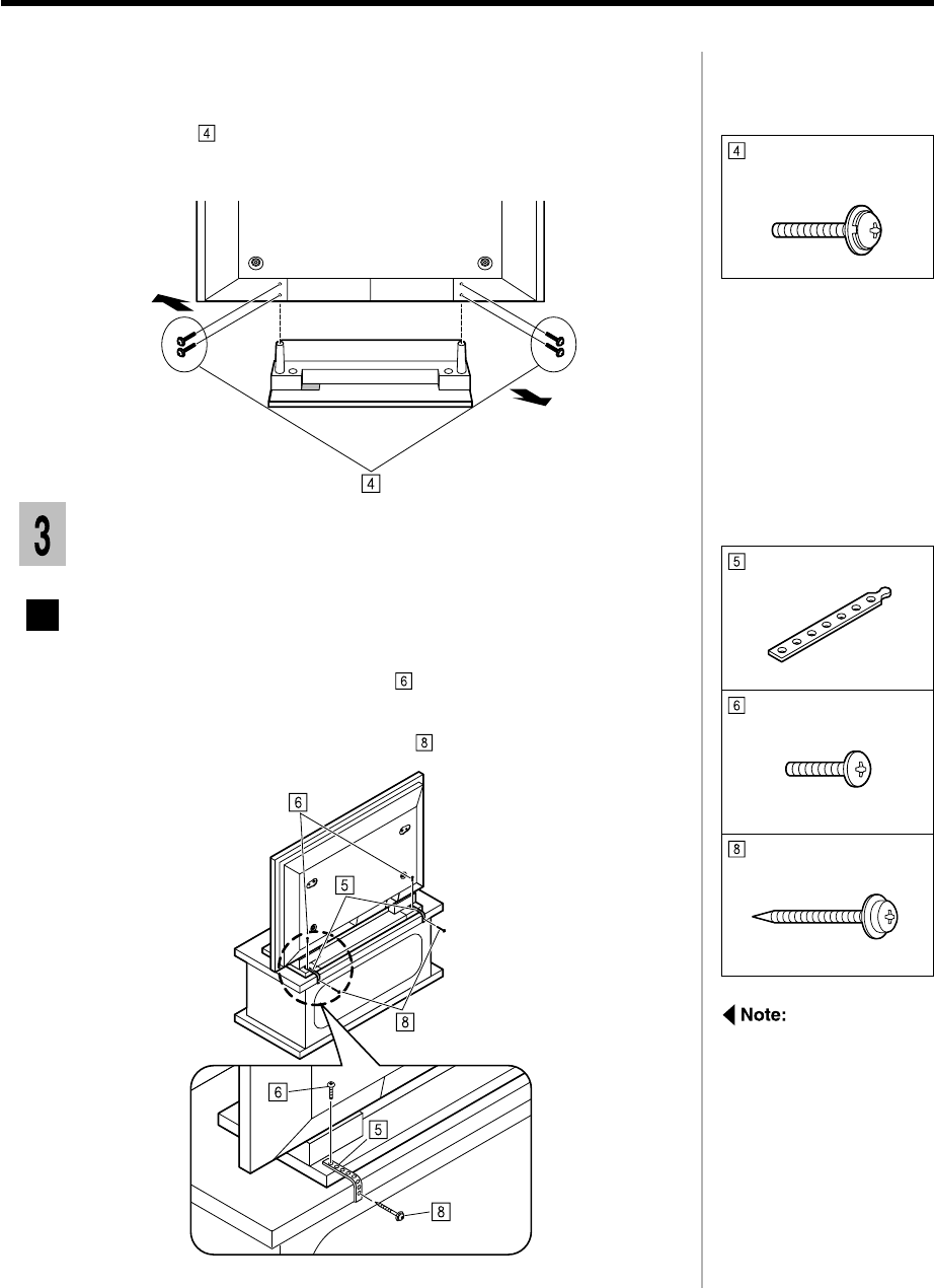
Fixing the display unit to a desk.
Screw the bands to the pedestal with screws.
1
Screw the bands to edge of a desk with screws.
2
Assembly screw
(M5-30) x 4
If you are using a
wooden desk, then use
the wood screws.
Use the appropriate
screws for the type of
material of the desk.
Band x 2
Black screw x 2
Wood screw x 2
1-4
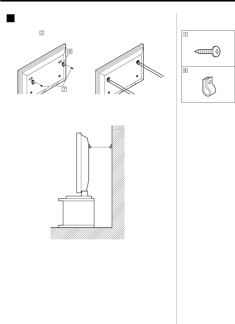
Fixing the display unit to the wall
Insert the screws and clamp into the holes at the back of the display
unit.
1
Use a strong wire or chain commercially available to fix the display unit
to a solid area of the wall or pillar.
2
Black screw x 2
Clamp x 4
2-1
Assembly diagram
CONTENTS
Description ................................................... 2-2
Instruction of the installation ...................... 2-3
1.Assembling the wall stand.................................. 2-3
2.Fixing the insulating spacers to the display unit ...... 2-4
3.Attaching the wall stand to the display unit ............ 2-6
4.Fixing the display unit to the wall ......................... 2-7
Removing the display unit........................... 2-8
Wall stand
TY-ST42PW1
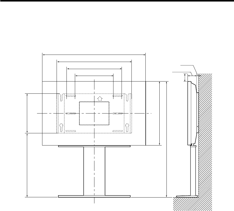
Description
Installation diagram
400 (15
3
/
4
)
610 (24
1
/
64
)
1116.5 (43
61
/
64
)
611.5 (24
5
/
64
)
744 (29
19
/
64
)
1020 (40
5
/
32
)
560 (22
1
/
16
)
390 (15
23
/
64
)89 (3
33
/
64
)
19 (
3
/
4
)
*100
Units : mm
2-2
* A clearance of at least 100mm at the top of the display unit should be provided.
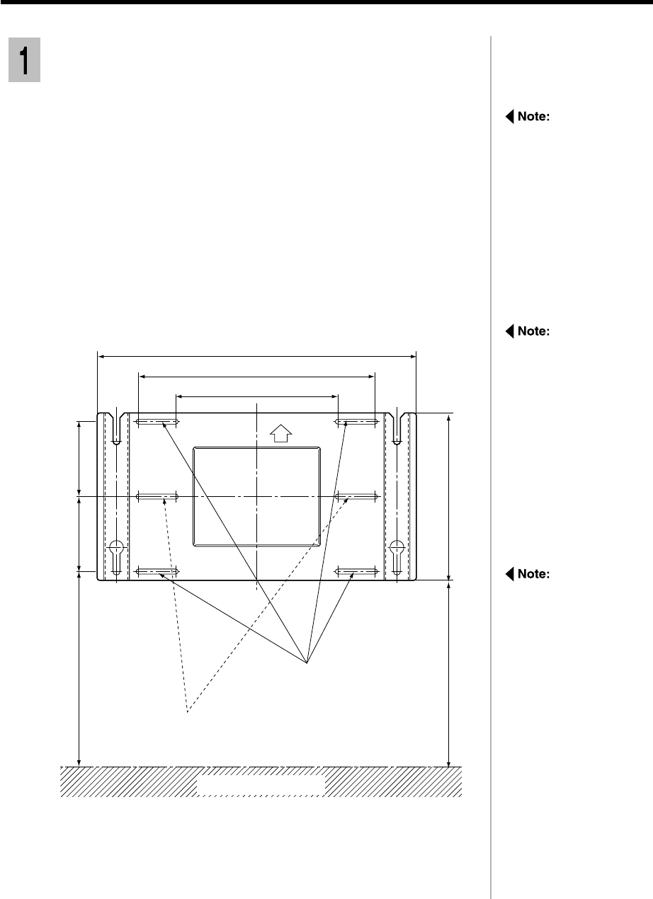
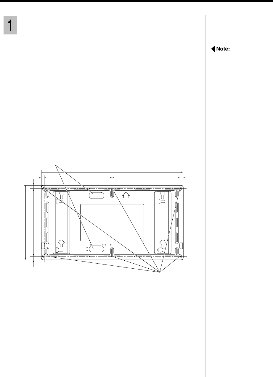
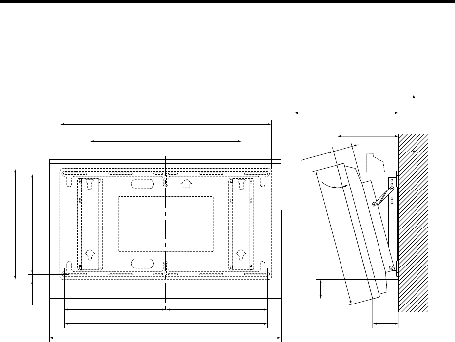
Instruction of the installation
Assembling the wall stand
Refer to the holding
bracket installation
measurements in the
drawing left. Ensure that
the wall is able to bear
the weight at each of the
4 upper and lower
installation locations.
Add reinforcement if any
of these locations are
not strong enough.
Check the strength of the installation location.
The height measurements marked ** are particularly important. Do not
attempt to set up the pedestal in a location where these dimensions and a
clearance of at least 100 mm at the top of the display unit should be provided.
1) On the wall, measure and mark a height 650 mm above the floor;
2) Measure and mark the location 475 mm horizontally to the right of
the mark you made in 1). Measure and mark points 180 mm and 360
mm above each mark (for a total of six marked locations);
3) Drill a hole at each of the six marked locations on the wall.
1
390 (1523/64)
180 (73/32)
631.5 (247/8)
611.5 (241/16)
180 (73/32)
400 (153/4)
Wall installation holes
(4 locations)
Spare wall installation holes
(2 locations)
560 (22 1/16)
744 (2919/64)
Floor surface
** **
Units : mm
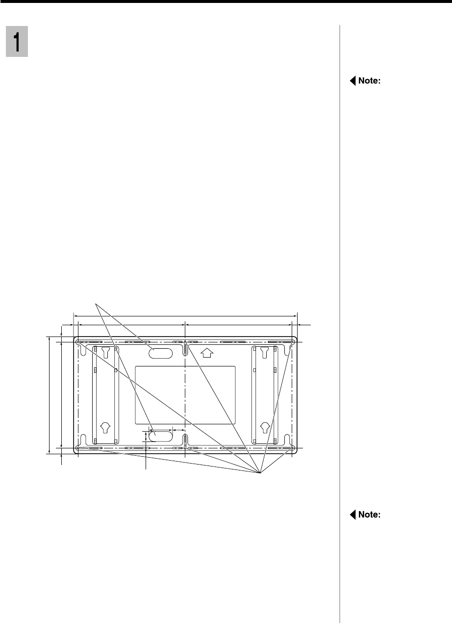
Ensure an area of at least
650 mm by 1,230 mm in
length at the location
where you plan to install
the holding bracket.
The holding bracket has
6 slits through which the
bracket can be fixed to a
wall with screws.
If the wall material does
not allow sufficient
strength by using six
installation holes, use
some of the spare holes.
However, depending on
the construction material
used at the place of
installation, cracks may
develop if the screws are
inserted too close to
each other.
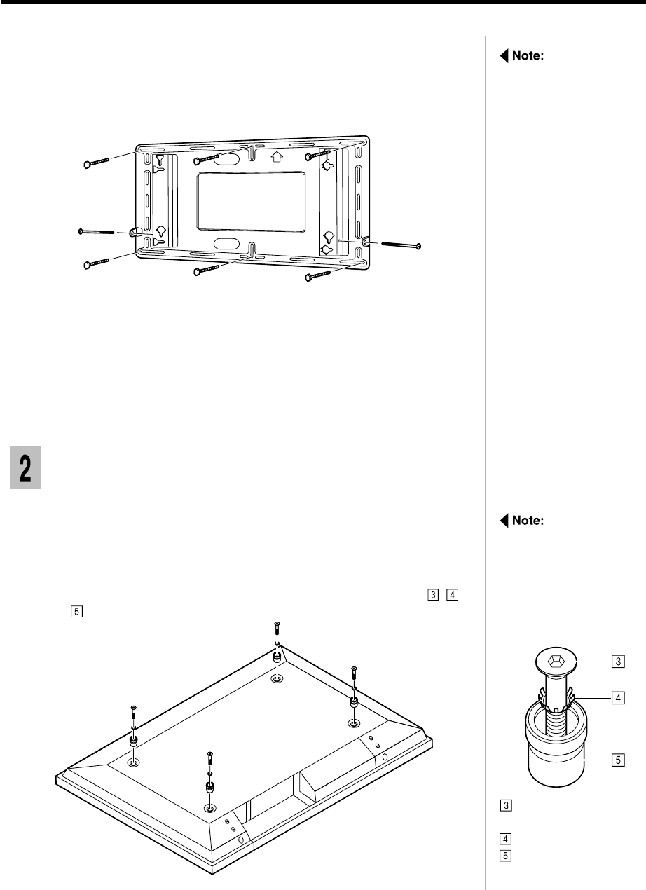
2-3
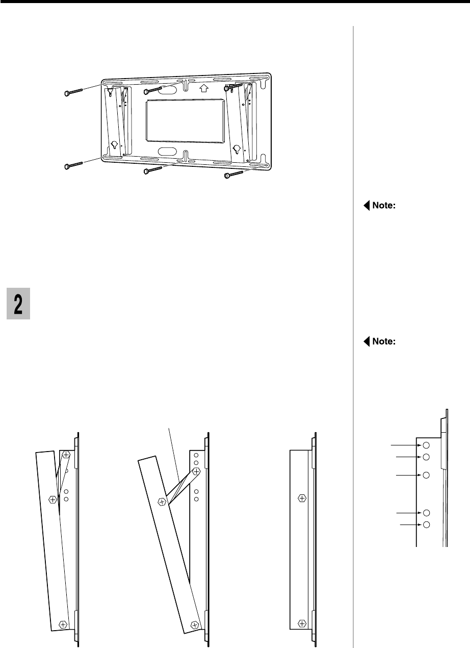
Fix a M6 screw, through any of the slits in the bracket, into the
corresponding hole in the wall.
Using a level along the top or bottom edge, ensure that holding bracket is
horizontal.
2
Fix the screws through the slits into the remaining three holes.
3
Provisionally tighten the fixing screws.
4
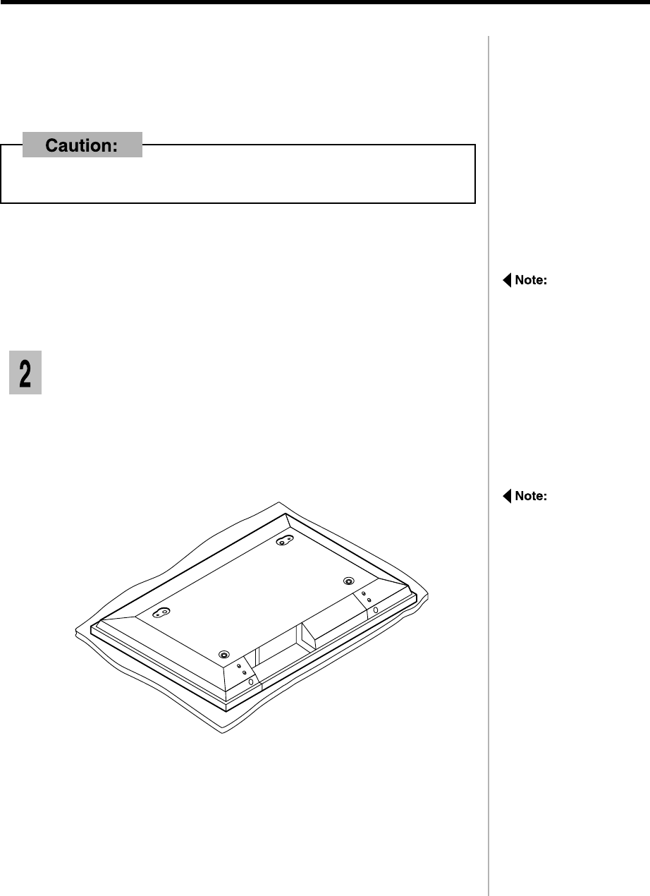
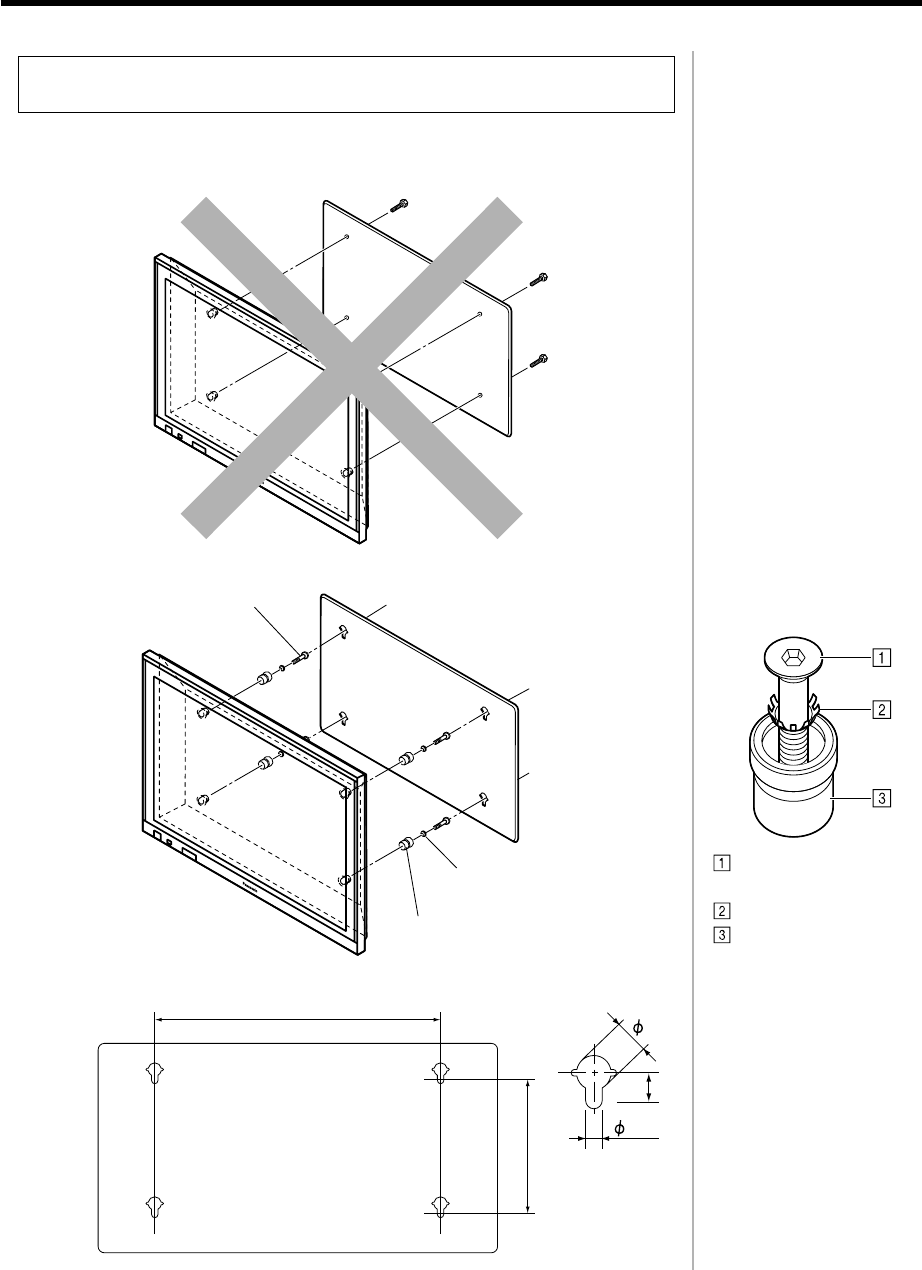
Fixing the insulating spacers to the display
unit
1) Spread a clean cloth over a level floor or base, and place it on the
display unit face down.
2) Remove the screws and covers.
Keep them in a safe place for possible future use.
1
The holding bracket must always be installed. It prevents the display unit from
falling after installation.
If the screws protrude
more than 5 mm, it will
not be possible to
properly install the
display unit.
Carefully place the Wide
Plasma Display face
down on top of a clean
cloth, which has been
spread over a flat
surface with no other
objects on it, and then
proceed to the next
step.
2-4
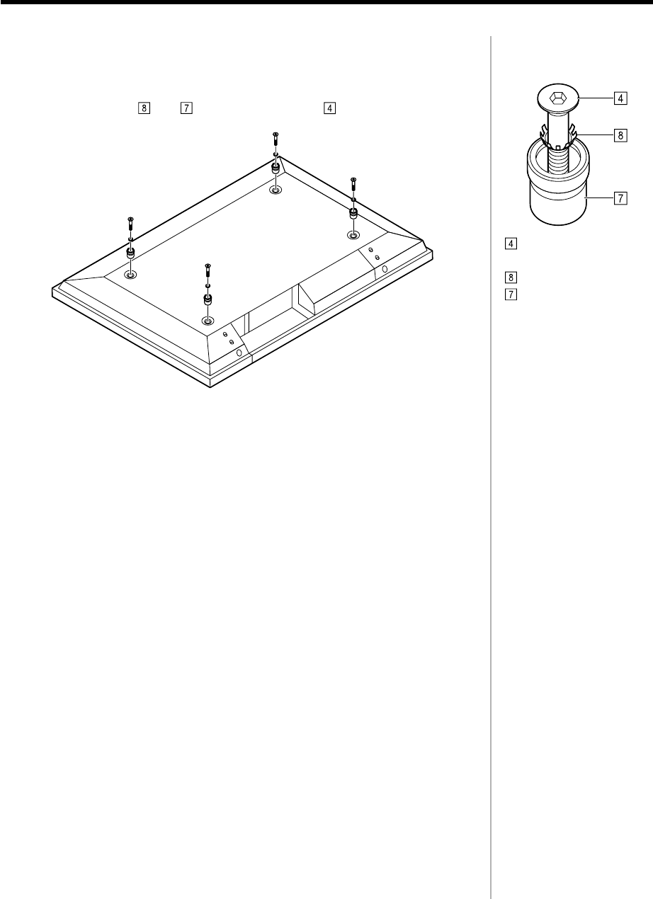
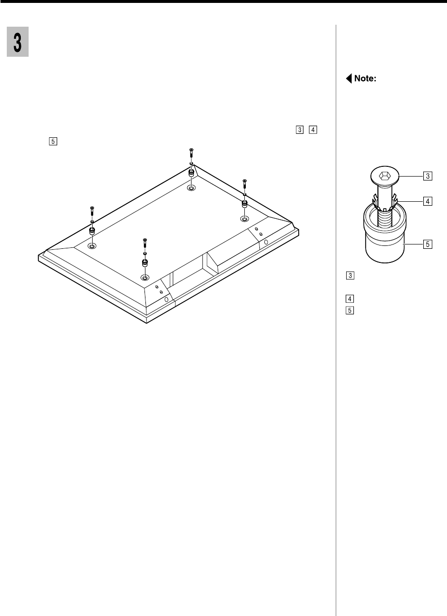
Remove the four screws.
2
As shown in the illustration, use the supplied "Allen key" to fasten the
screw through and , then screw the four to the display unit.
3
Pan head bolt with
hex socket
Toothed pan washer
Insulating spacer
2-5
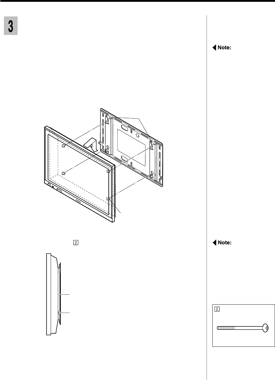
Attaching the wall stand to the display unit
Insert the two poles at the top of the wall pedestal into the holes in the
base of the display unit as shown in the illustration.
1
Insert the four screws, two on either side, into the holes in the back
of the display unit and fasten them into the holes in the inserted poles.
2
The screws and covers
may be required later if
the display unit is moved
and mounted directly to
a wall, so keep them in
a safe place so that they
will not get lost.
Assembly screw
(M5-30) x 4
2-6
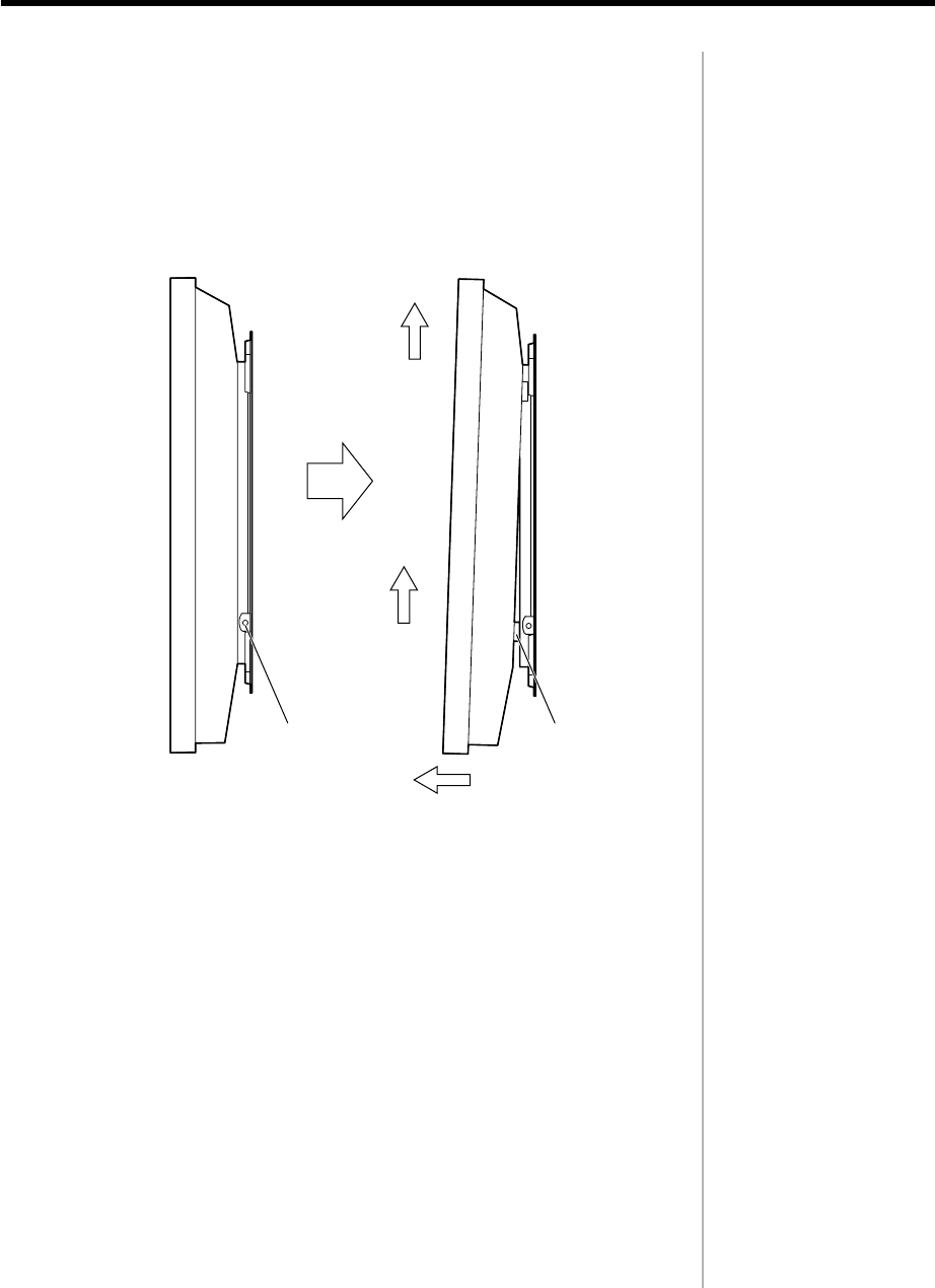
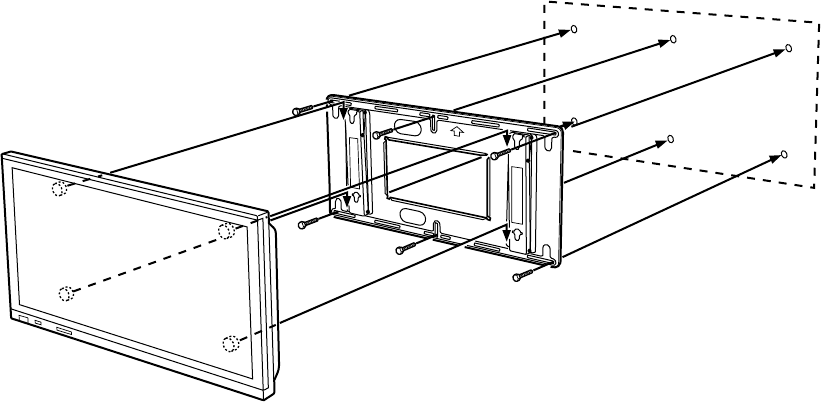
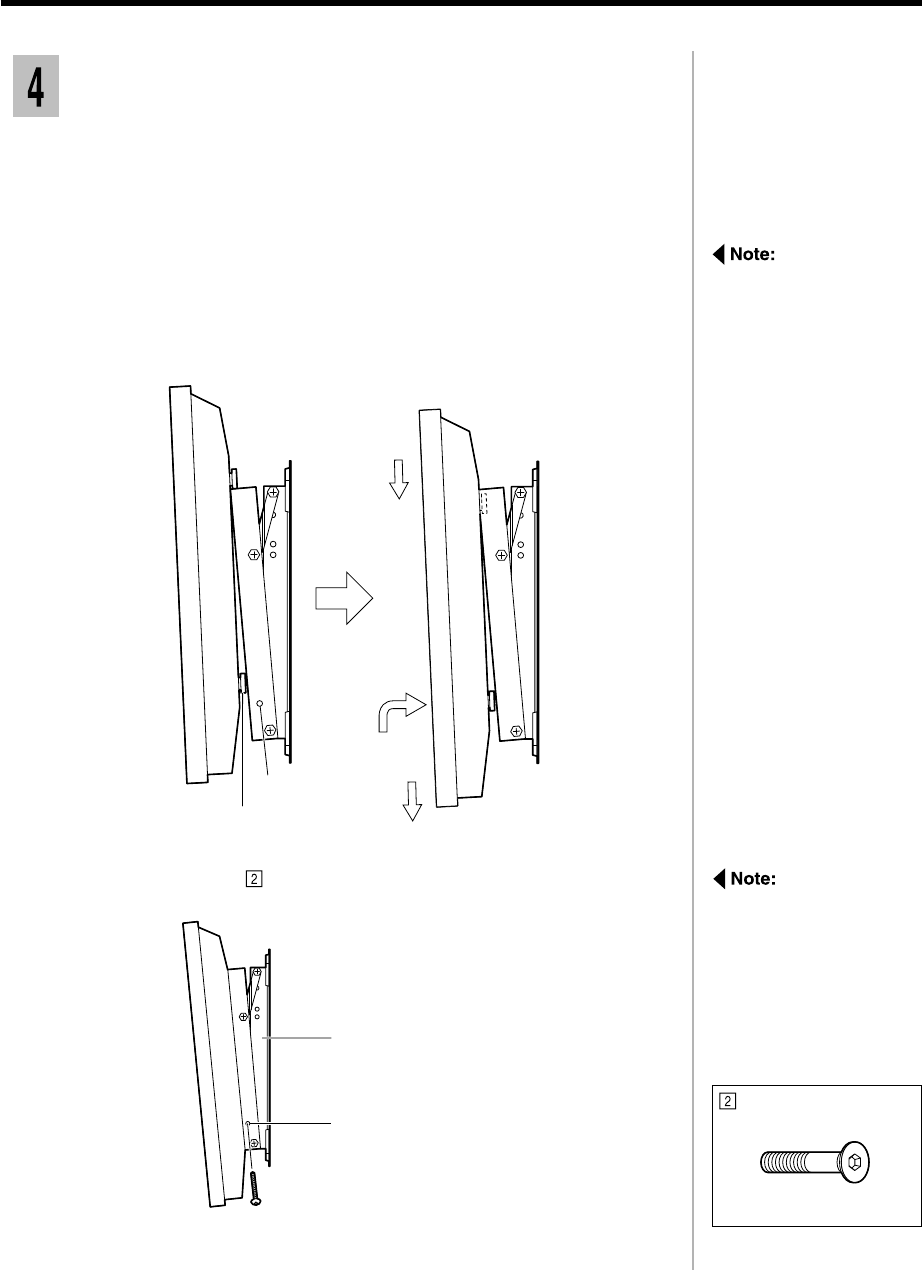
Fixing the display unit to the wall
Lift the display so that the upper insulating spacers at the back may fit
into the notched indentation at the top of the holding bracket, and then
lower the display into place.
1
1) Lift the display slightly and insert the lower insulating spacers at the
back of the display unit into the lower cutouts in the holding bracket.
2) Lower the display into the lower notched part of the cutouts.
2
Do not lift the display
too high or it may come
out of the notches in the
upper indentations.
Insert and fasten the screws at both the left and right sides.
3
To prevent the display
unit from becoming
detached from the
holding bracket, make
sure that both the left
and right fixing screws
are properly fitted.
Fixing screws (left and right)
Holding bracket
Fixing screw(M5)
2-7
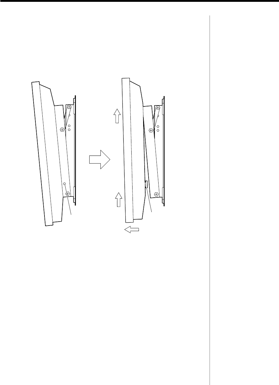
Remove the two fixing screws from the sides of the holding bracket.
1
1) Lift the display slightly;
2) Pull the bottom half way to detach the lower insulating spacers;
3) Lift the display away from the holding bracket.
2
Removing the display unit
Fixing screws
(left and right)
Holding
bracket
Insulating
spacer
1)
3)
2)
2-8
Assembly diagram
CONTENTS
Description ................................................... 3-2
Instruction of the installation ...................... 3-3
1.Assembling the mobile stand .............................. 3-3
2.Fixing the display unit to the stand ....................... 3-4
3.Fixing the wiring............................................... 3-5
Removing the display unit........................... 3-6
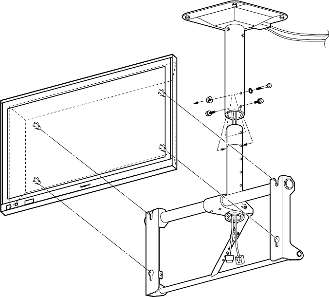
Mobile stand
TY-ST42PF3
3-1
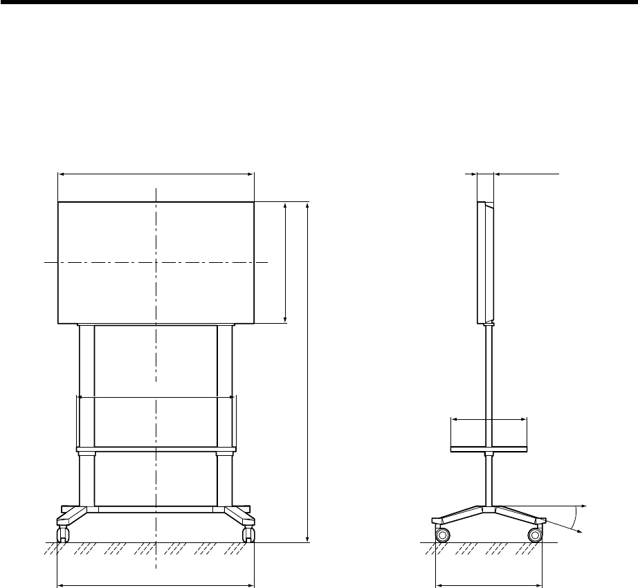
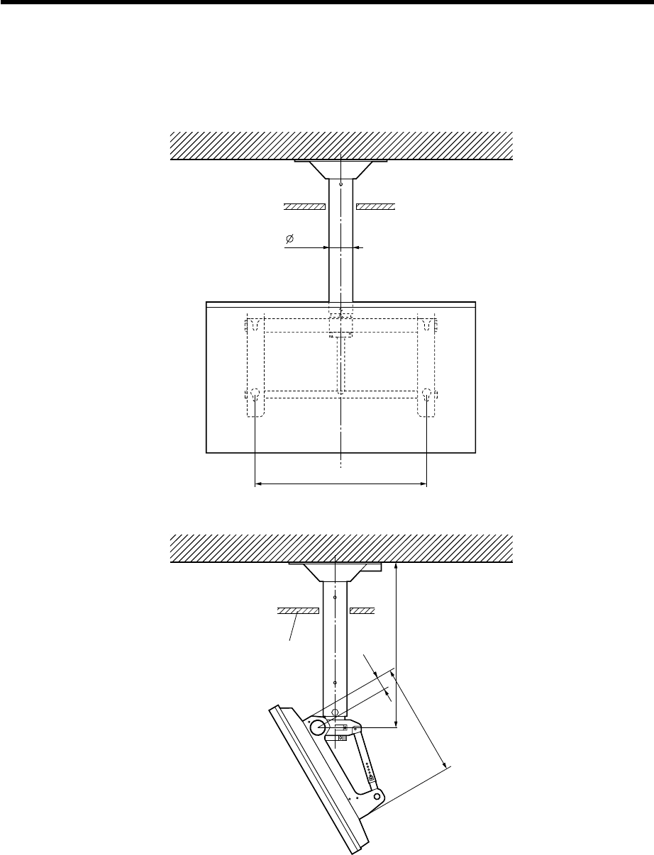
Description
Installation diagram
Units : mm
1020 (40 5/32)
610 (24 1/64)
1637 (64 29/64)
1030 (40 9/16) 650 (25 19/32)
400 (15 3/4)
15°
89 (3 33/64)
820 (32 5/16)
3-2
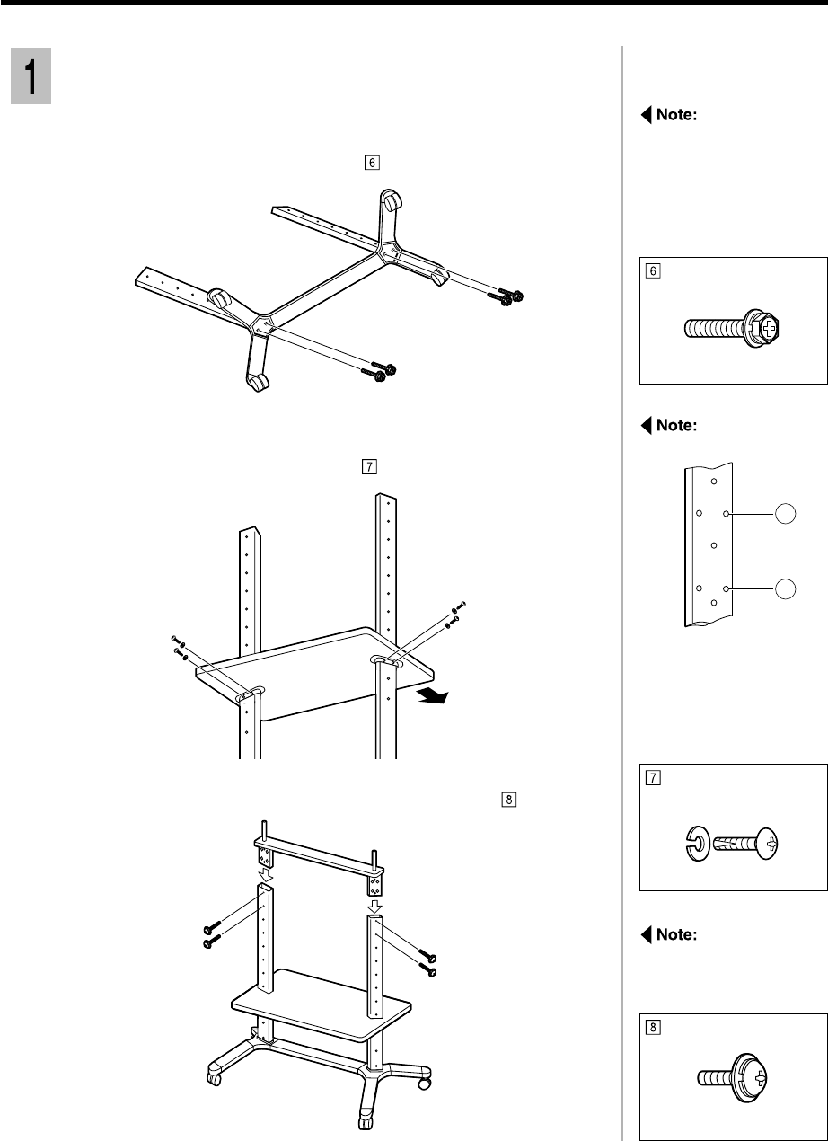
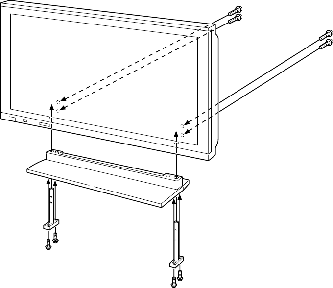
Instruction of the installation
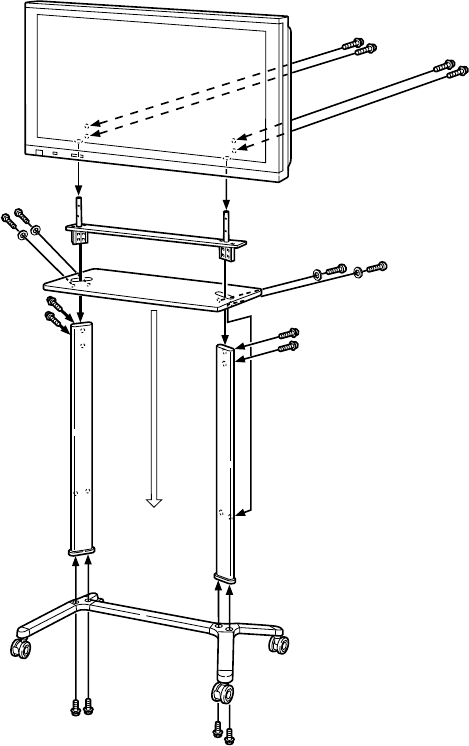
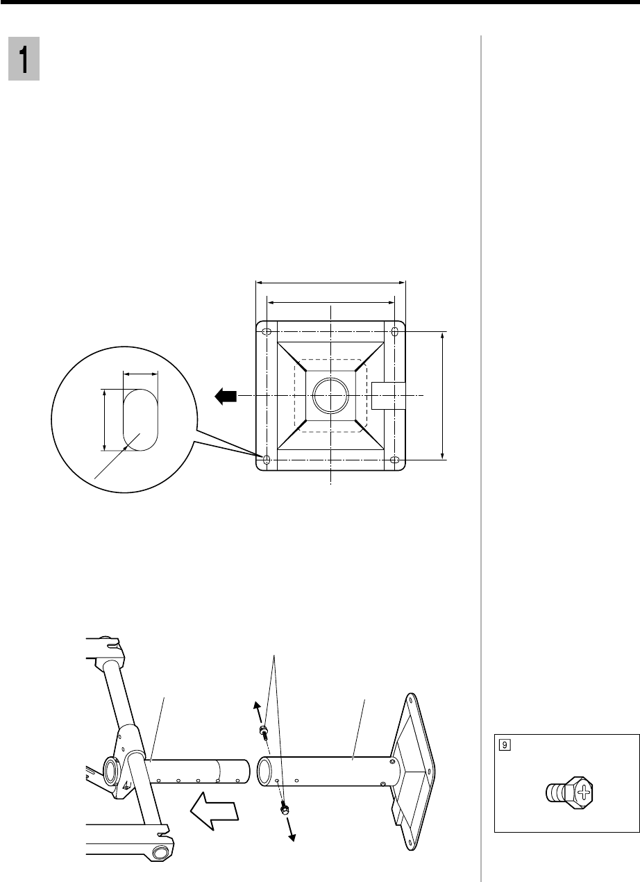
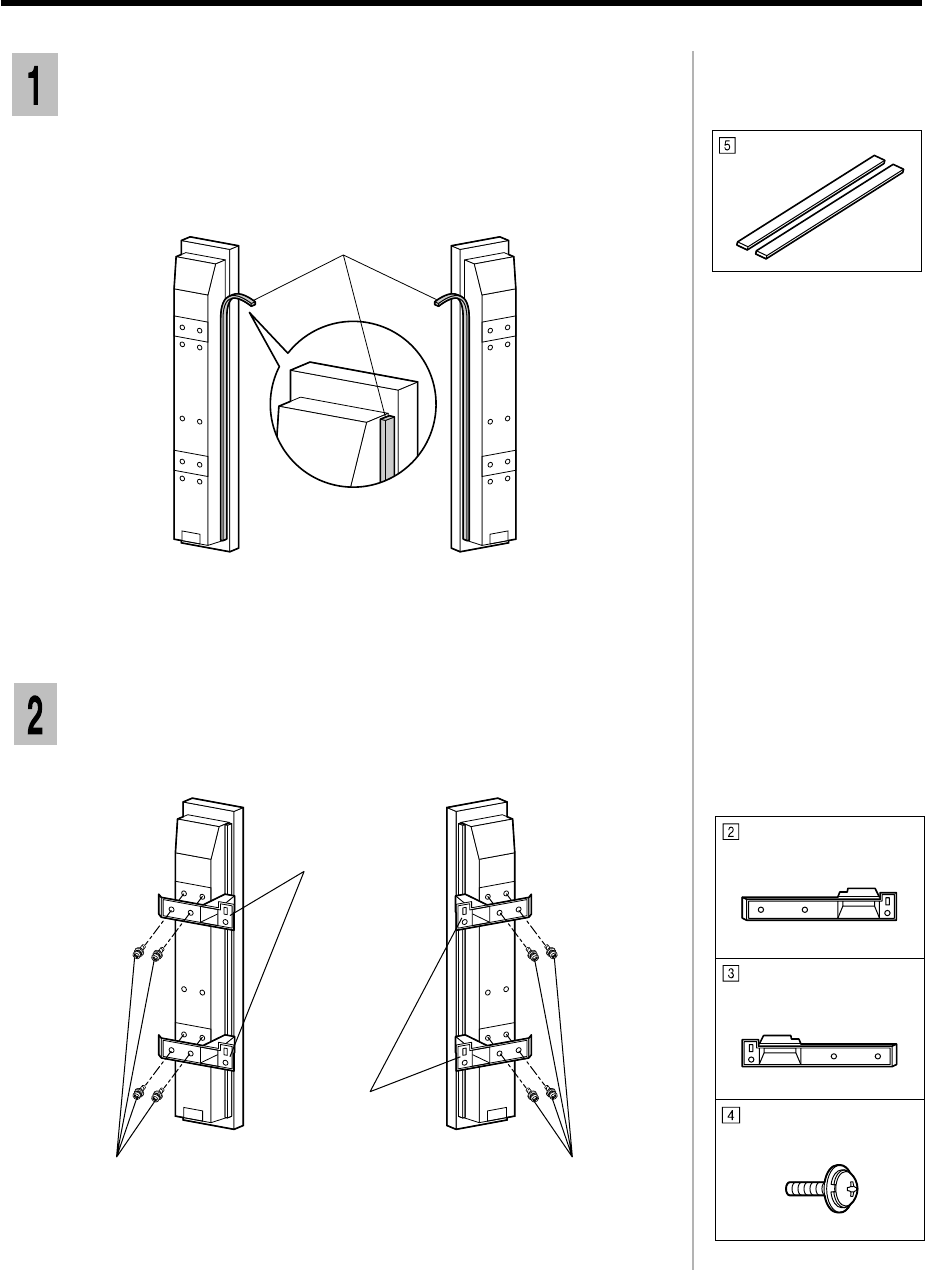
Assembling the mobile stand
Slide the shelf, with the supports in the slots, down to the required
height. Choose the locations of stopper holes to match the required
height. Then fix the shelf using the four screws and spring washers.
2
Front
Insert the holder into the supports, and fix it with the four screws.
3
When installing the stand,
provisionally fasten all
bolts and screws first,
and then fasten them to
complete the assembly.
Bolt (M8)
Support
Choose the locations of
the stopper holes to
match the required height.
1) height of 500 mm
2) height of 350 mm
1
2
Be sure to assemble on a
stable horizontal surface.
Assembly screw (M6-16)
and spring washer x 4 each
Assembly screw(M5-15)
3-3
Insert the supprots into the slots on the upper side of stand base, and
then fix them from below using the four bolts.
1
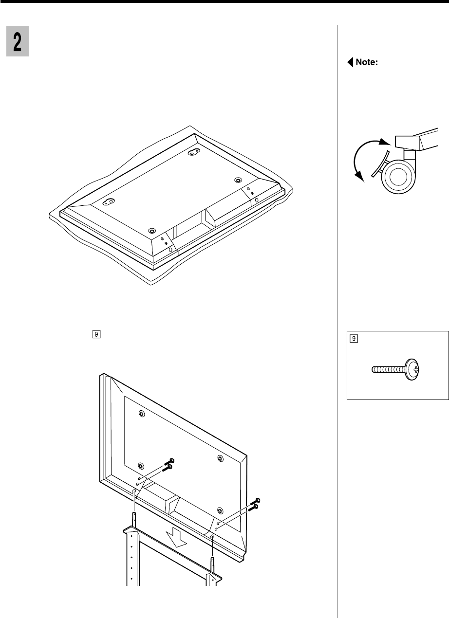
Fixing the display unit to the stand
Lock the casters before
installing the display unit.
Press down the caster
switch to lock the caster.
Unlock
Lock
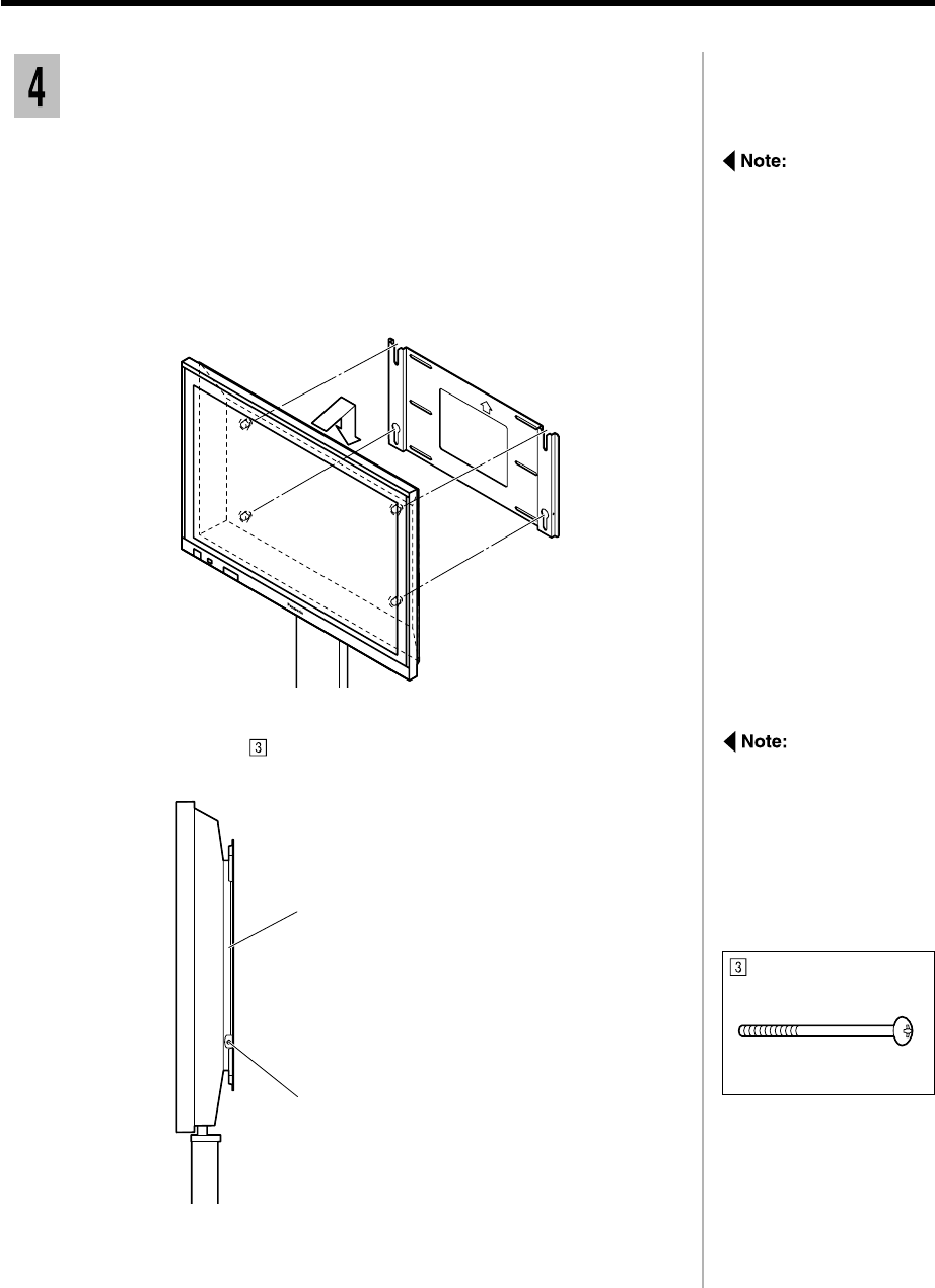
1) Spread a clean cloth over a level floor or base, and place on it the
display unit face down.
2) Remove the screws and covers.
Keep them in a safe place for possible future use.
1
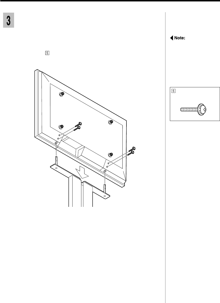
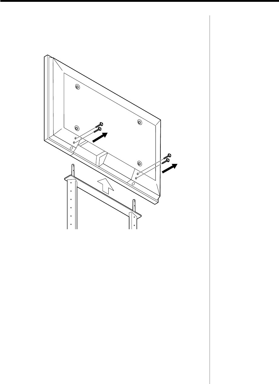
Insert the two poles at the top of the stand into the holes in the base of
the display unit as shown in the illustration below.
2
Insert the four screws, two on each side, into the holes in the back of
the display unit and fasten them into the holes in the inserted poles.
3
Assembly screw (M5-30)
3-4
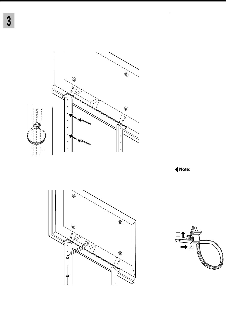
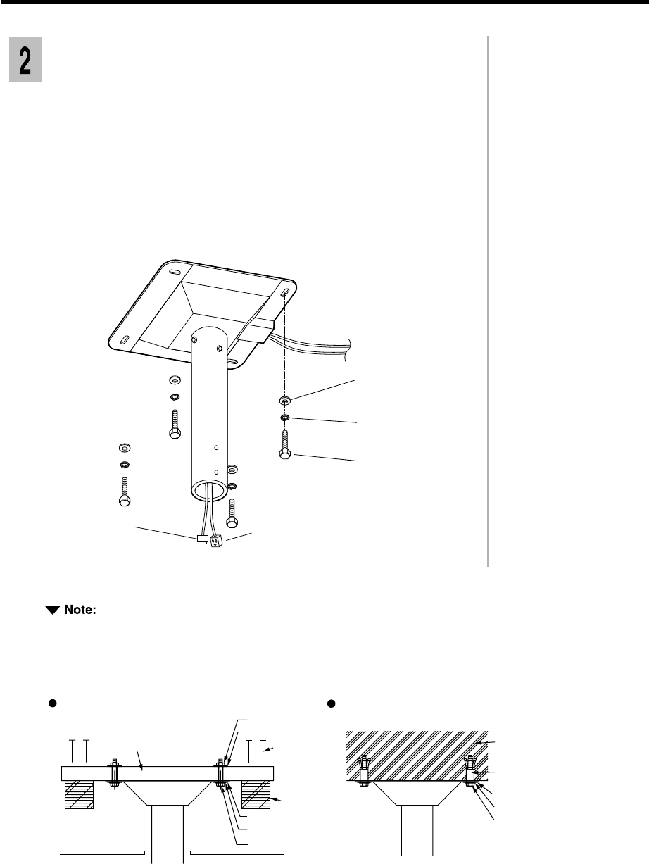
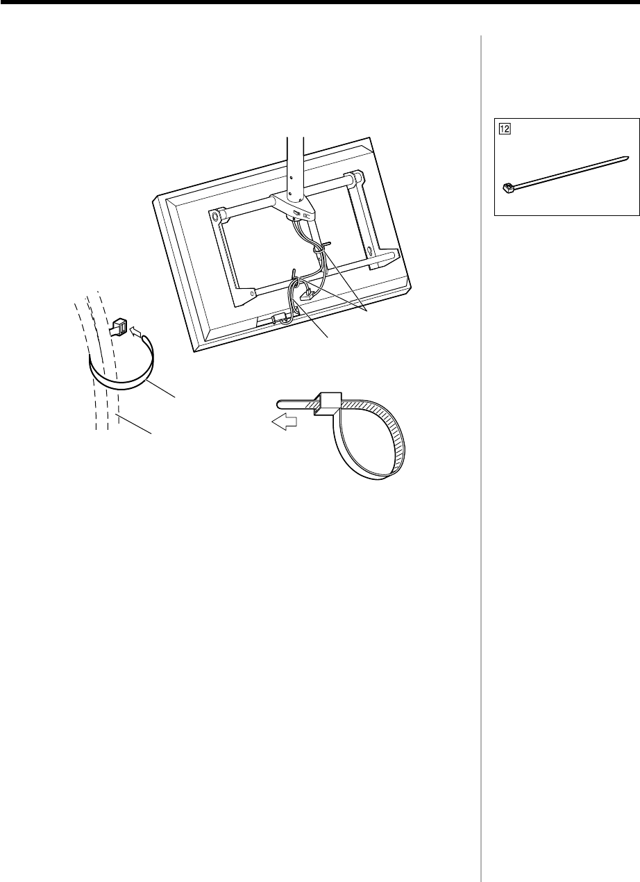
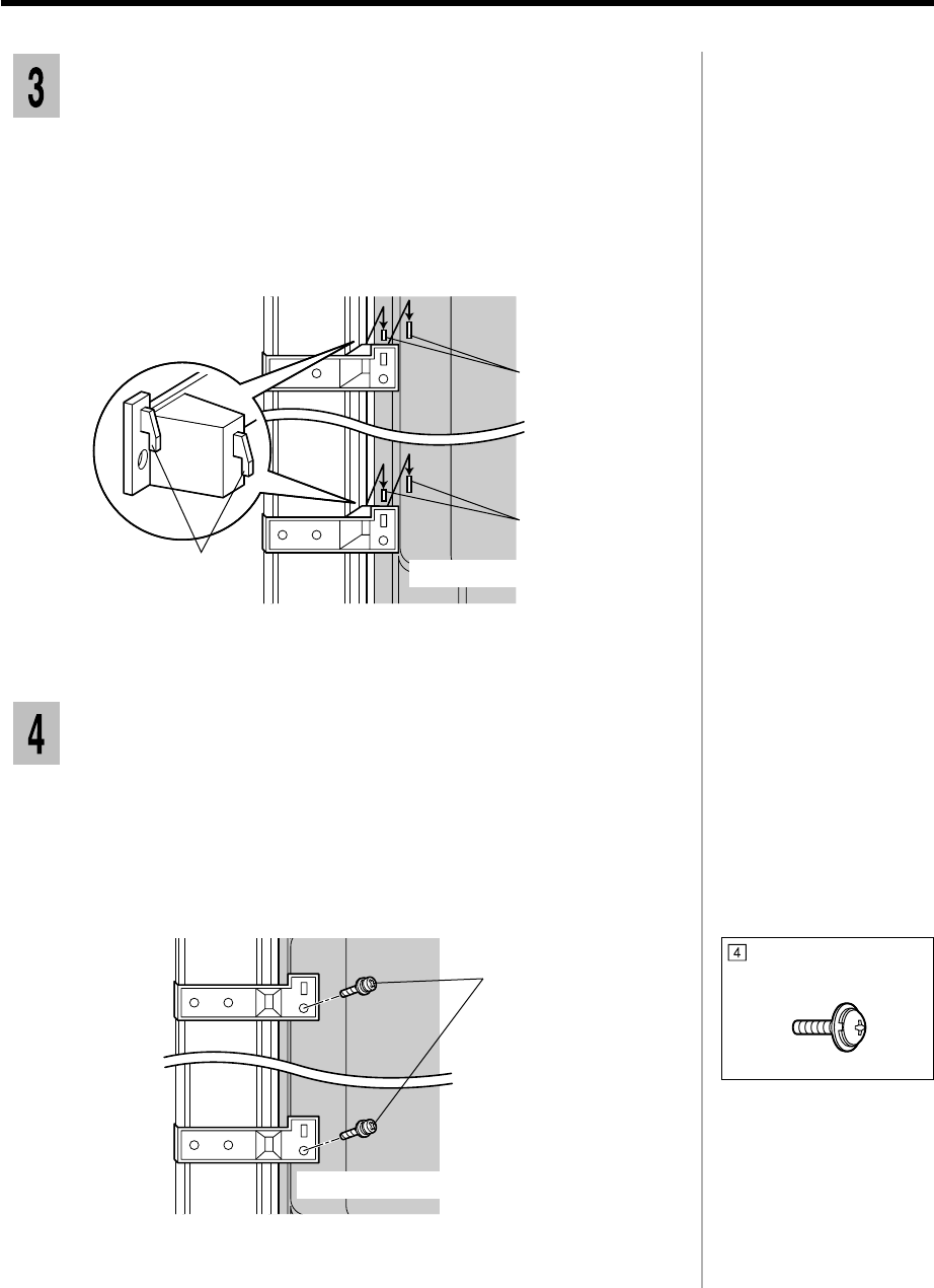
Fixing the wiring
Insert the accessrory cable straps, evenly spaced, into the appropiate
mounting holes in the rear of the support.
1
Cable
Cablestraps
Bring together the input cables which are connected to the terminals at
the bottom of the display unit and secure them with the five cable
straps.
2
To loosen cable straps:
1. Push the strap in the
direction of the arrow
in the diagram; and
2.Loosen the cable
strap by passing it
through the cramping
hole.
3-5
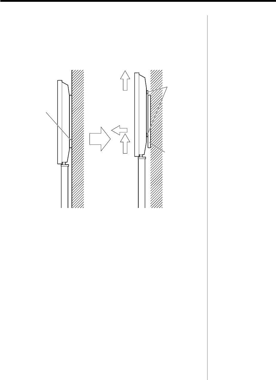
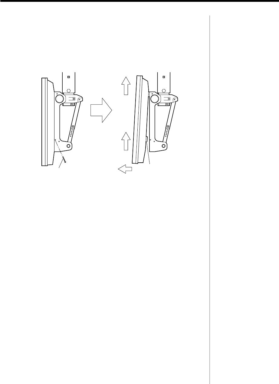
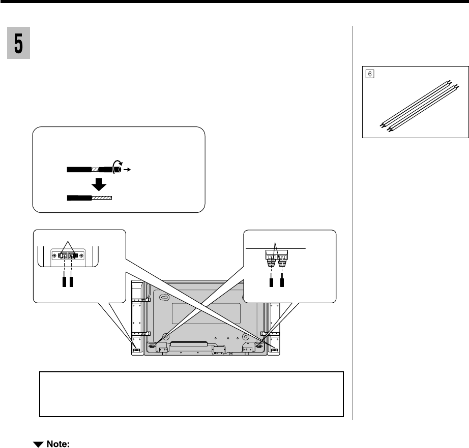
Loosen and remove the four screws from the display unit.
1
Removing the display unit
Lift the display unit away from the stand.
2
2
1
3-6
4-1
Wall-hanging bracket
(vertical)
TY-WK42PV1
Assembly diagram
CONTENTS
Description ................................................... 4-2
Instruction of the installation ...................... 4-4
1.Fixing the wall-hanging bracket to the wall ............ 4-4
2.Fixing the insulating spacers to the display unit ...... 4-5
3.Attaching the display unit to
the wall-hanging bracket................................ 4-6
Removing the display unit........................... 4-7
Warning ......................................................... 4-8
Description
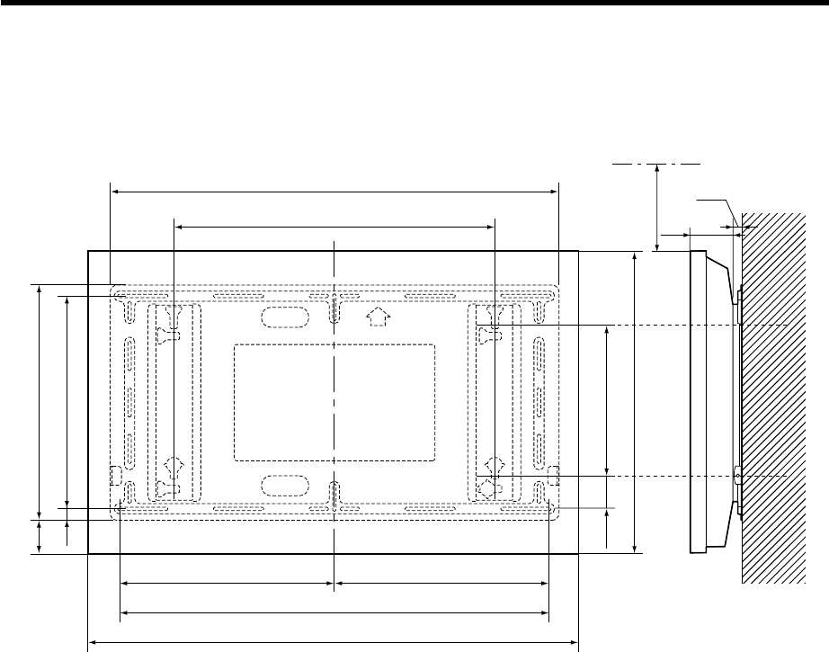
Installation diagram
Units : mm
4-2
* A clearance of at least 100mm at the top of the display unit should be provided.
660
450
20
320
610
900
450 450
1020
69.5
55.5
490
930
89
*100
19
4-3
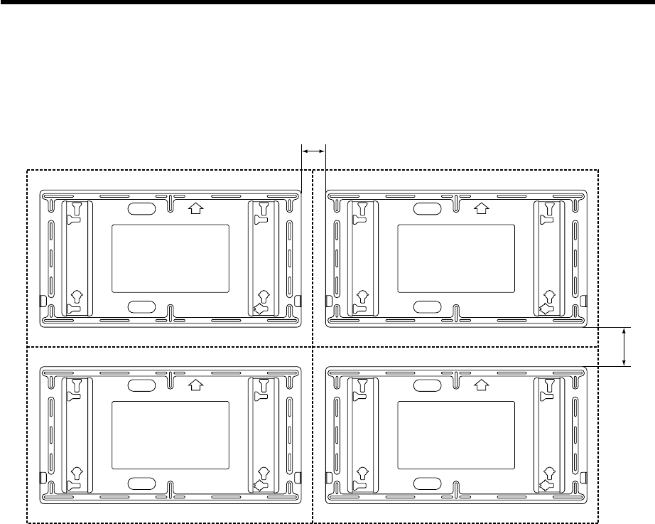
Installation diagram
For Multi Screen
Units : mm
90
120
* Installe lower panel unit first.
Instruction of the installation
Fixing the wall-hanging bracket to the wall
Check the strength of the installation location
The wall-hanging bracket weighs approximately 6kg, and the display unit by
itself weighs 33kg. Refer to the wall-hanging bracket installation dimensions
in the diagram below to, check the strength of the wall in six installation locations,
and add reinforcement if any of these locations are not strong enough.
1) Select an installation site with an area of at least 1,500 mm wide by
800 mm high. Refer to the figure to make a positioning mark for the
location of the center-top hole.
2) Measure and mark the locations 450 mm to the left and 450 mm
horizontally to the right of the location you marked in 1).
3) Measure and mark the locations 450 mm below each of the marked
location.
1
Units : mm
930
490
450
50
30
2020
450450
100 50
15 15
Wall installation holes(6 locations)
Used for routing wires behind a wall
The wall-hanging bracket
has installation holes
provided at 24 locations.
If the wall material does
not allow sufficient
strength by using six
installation holes, use
some of the spare
holes.
However, depending on
the construction
material used at the
place of installation,
cracks may develop if
the screws are inserted
too close to each other.
4-4
If required, use commer-
cially available M6
bolts which suit the wall
materials.
If the Screws protrude
more than 5 mm, it will
not be possible to install
the Wide Plasma Display
in the correct position.
Place the display unit
face down on top of a
cloth clean and free from
otherforegin particles,
and then proceed to the
next step.
Spread a clean cloth over a level floor or base, and place on it the display
unit face down.
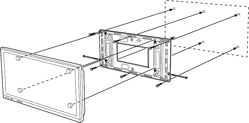
Remove the four screws from the display.
1
Use the accessory tool "Allen key" to install the four accessory ,
and into the holes.
2
Fixing the insulating spacers to the display
unit
Pan head bolt with
hex socket
Toothed pan washer
Insulating spacer
3Use a level gauge to correct the alignment of the wall-hanging bracket,
and screw bolts into the remaining five holes.
Insert and fasten a M6 screw bolt into the center-top hole.
2
Provisionally tighten the fixing screws.
4
4-5
Lift the display unit so that the upper insulating spacers at the back
may fit into the notched indentation at the top of the wall-hanging
bracket, and then lower the display unit into place.
1
1) Lift the display unit slightly and insert the lower insulating spacers
at the back of the display unit into the lower cutouts in the wall-
hanging bracket.
2) Lower the display unit into the lower notched part of the cutouts.
2
Do not lift the display
too high or it may come
out of the notches in the
upper indentations.
Insert and fasten the screws at both the left and right sides.
3
To prevent the display unit
from becoming detached
from the wall-hanging
bracket, make sure that
both the left and right
fixing screws are properly
fitted.
Attaching the display unit to the wall-
hanging bracket
Notches
Insultating spacer
Holding bracket
Fixing screws(left and right)
Fixing screw(M5)
4-6
1) Lift the display slightly;
2) At the same time, pull the bottom half way to detach the lower insulating
spacers;
3) Lift the display away from the wall-hanging bracket.
2
Removing the display unit
1Remove the two fixing screws from the sides of the wall-hanging
bracket.
Fixing srews
(left and right) lower insulating
spacer
3)
1)
2)
4-7
Warning
IF UN OFFICIAL BRACKET IS USED.
Do not fix. The display unit with un official bracket by bolts directly, the display unit
may damage and possibly electrical interfalance for other electronics equipment.
660
320
22
14
29
Pan head bolt with
hex socket
Toothed pan washer
Insulating spacer
4-8
Pan head bolt with
hex socket
Insultating spacer
Toothed pan washer
CONTENTS
Description ................................................... 5-2
Instruction of the installation ...................... 5-3
1.Fixing the wall-hanging bracket to the wall ............ 5-3
2.Adjusting the angle of the display fitting ................ 5-4
3.Fixing the insulating spacers to the display unit ...... 5-5
4.Attaching the display unit to
the wall-hanging bracket................................ 5-6
Removing the display unit........................... 5-7
Wall-hanging bracket
(angled)
TY-WK42PR1
Assembly diagram
5-1
Description
Installation diagram
Units : mm
5-2
450 450
45020
490
660
900
1020
930
89
610
**310
*100
* A clearance of at least 100mm at the top of the display unit should be provided.
** Installation of the wall-hanging bracket requires a depth of 310 mm.
Instruction of the installation
Fixing the wall-hanging bracket to the wall
The wall-hanging bracket
has installation holes
provided at 14 locations.
If the wall material does
not allow sufficient
strength by using six
installation holes, use
some of the spare holes.
However, depending on
the construction material
at used at the place of
installation, cracks may
develop if screws are
inserted too close to
each other.
Check the strength of the installation location
The wall-handing bracket weighs approximately 6kg, and the wide plasma
display unit by itself weighs 33kg. Refer to the wall-hanging bracket installation
dimensions in the diagram below to check the strength of the wall in six
installation locations, and add reinforcement if any of these locations are not
strong enough.
Further installation of the wall-hanging bracket requires a depth of 310 mm.
1) Select an installation site with an area of at least 1,500 mm wide by
800 mm high. Referring to the figure, make a positioning mark for
the location of the center-top hole;
2) Measure and mark the locations 450 mm to the left and 450 mm
horizontally to the right of the location you marked in 1);
3) Measure and mark the locations 450 mm below each of the marked
location.
1
Units : mm
930
490
450 2020
450450
15 15
5030
100 50
Wall installation holes(6 locations)
Used for routing wires behind a wall
Insert and fasten a M6 screw bolt into the center-top hole.
2
If required, use
commercially available
M6 bolts which suit the
wall materials.
5-3
Adjusting the angle of the display fitting
If the screws protrude
more than 5 mm, it will
not be possible to install
the Wide Plasma Display
in the correct position.
Use a level gauge to correct the alignment of the wall-hanging bracket,
and screw bolts into the remaining five holes.
3
5-4
The stay is not needed if
the display unit is to be
fixed vertically.
Angle adjustment positions
The angle of the display fitting can be adjusted to one of the five positions
ranging from vertical to 20 tilt in 5 steps.
At the time of shipment, the angle of tilt is set to 5 from vertical. To change
this angle, adjust the position of the stay.
5tilt
10tilt
15tilt
20tilt
No tilt
5
10
15
20
0
stay
5 tilt 15 tilt No tilt
Provisionally tighten the fixing screws.
After determining the positions and checking them against the bracket,
embed M6 bolts or nuts. Furthermore, when embedding the bolts, ensure
that the bolts protrude from the wall by 10 to 15 mm.
4
Place the display unit
face down on top of a
cloth clean and free from
otherforegin particles,
and then proceed to the
next step.
Spread a clean cloth over a level floor or base, and place on it the display
unit face down.
Remove the four screws from the display.
1
Use the accessory tool "Allen key" to install the four accessory ,
and into the holes.
2
Fixing the insulating spacers to the display
unit
Pan head bolt with
hex socket
Toothed pan washer
Insulating spacer
5-5
5-6
Do not lift the display
too high or it may come
out of the notches in the
upper indentations.
Insert and fasten the screws at both the left and right sides.
4
To prevent the display
unit from becoming
detached from the wall-
hanging bracket, make
sure that the left and
right fixing screws are
properly fitted.
Attaching the display unit to the wall-
hangingbracket
After that, lift the display unit slightly and insert the lower insulating
spacers at the back of the display unit into the lower cutouts in the
wall-hanging bracket.
2
Then lower the display unit into the lower notched part of the cutouts.
3
Fixing screws
Insulating spacer
1
2
3
Fixing screws mounts
Wall-hanging bracket
Fixing screws(left and right)
Lift the display unit so that the upper insulating spacers at the back
may fit into the notched indentation at the top of the wall-hanging
bracket, and then lower the display unit into place.
1
Fixing screw (M5-35)
Removing the display unit
1Remove the two fixing screws from the sides of the wall-hanging
bracket.
Insulating spacer
Foxing screws
(left and right)
3)
1)
2)
1) Lift the display unit slightly;
2) At the same time, pull the bottom half way to detach the lower insulating
spacers;
3) Lift the display away from the wall-hanging bracket.
2
5-7
6-1
Assembly diagram
CONTENTS
Description ................................................... 6-2
Instruction of the installation ...................... 6-3
1.Assembling the ceiling unit................................. 6-3
2.Prepare the ceiling unit...................................... 6-4
3.Prepare the display........................................... 6-6
4.Mount the display in the ceiling unit ..................... 6-7
Removing the display unit........................... 6-8
Celing unit
TY-CE42PS1
Description
Installation diagram
Units : mm (in.)
626~926
Ceiling board
50
431
660
89
6-2
Instruction of the installation
Assembling the ceiling unit
Units : mm (in.)
300 (1126/32)
300 (11
26
/
32
)
350 (1325/32)
Ceiling installation holes
Front
24 (
15
/
16
)
14 (35/64)
R7
(R9/32)
6-3
Ceiling unit
(upper section)
Fixing bolt (M8-12)
Ceiling unit
(lower section)
Check the strength of the installation location.
This ceiling unit weighs approx. 19kg (41.9lbs).The display weights approx.
33kg (72.8lbs) to 45kg (99.2lbs). Refer to the diagram on the right and
confirm that the four points for mounting the ceiling unit and display are
capable of bearing this weight. If the installation location is not strong
enough to bear this weight, reinforce the ceiling before the ceiling unit and
display are installed.
1
Prepare the ceiling unit.
Remove the two Fixing bolts (M8-12) from the ceiling unit and separate the
upper and lower sections of the unit.
2
Fixing bolt (M8-12) x 2
6-4
Flat washer
(not supplied)
Spring washer
(not supplied)
M12 bolt
(not supplied)
Earthed mains extension lead
(example)
Signal cable
(example)
• Reinforce the ceiling if it is not strong enough.
• Use bolts appropriate for the ceiling material (not supplied).
• Refer to the installing examples for wooden structure and concrete structure.
M12 bolt
Spring washer
Flat washer
curled plug(M12)
Anchor nut or
Concrete
Installing to a concrete structure(example)Installing to a wooden structure(example)
M12 bolt
Spring washer
Flat washer
Flat washer
Nut
Beam
"
]
)(min.thickness 40mm [1
9
/
16
Mounting plate
Ceiling board
Nail
Installation the ceiling unit.
Attach the ceiling unit (upper section)
1) Before installing the upper section, pull the wiring through the pipe.
Use an earthed mains extension lead (not supplied).
2) Make holes in the ceiling using a method appropriate for the ceiling
structure and for inserting M12mm bolts. Install the upper section
using a hex socket bolt (M12 not supplied), flat washer and spring
washer.
1
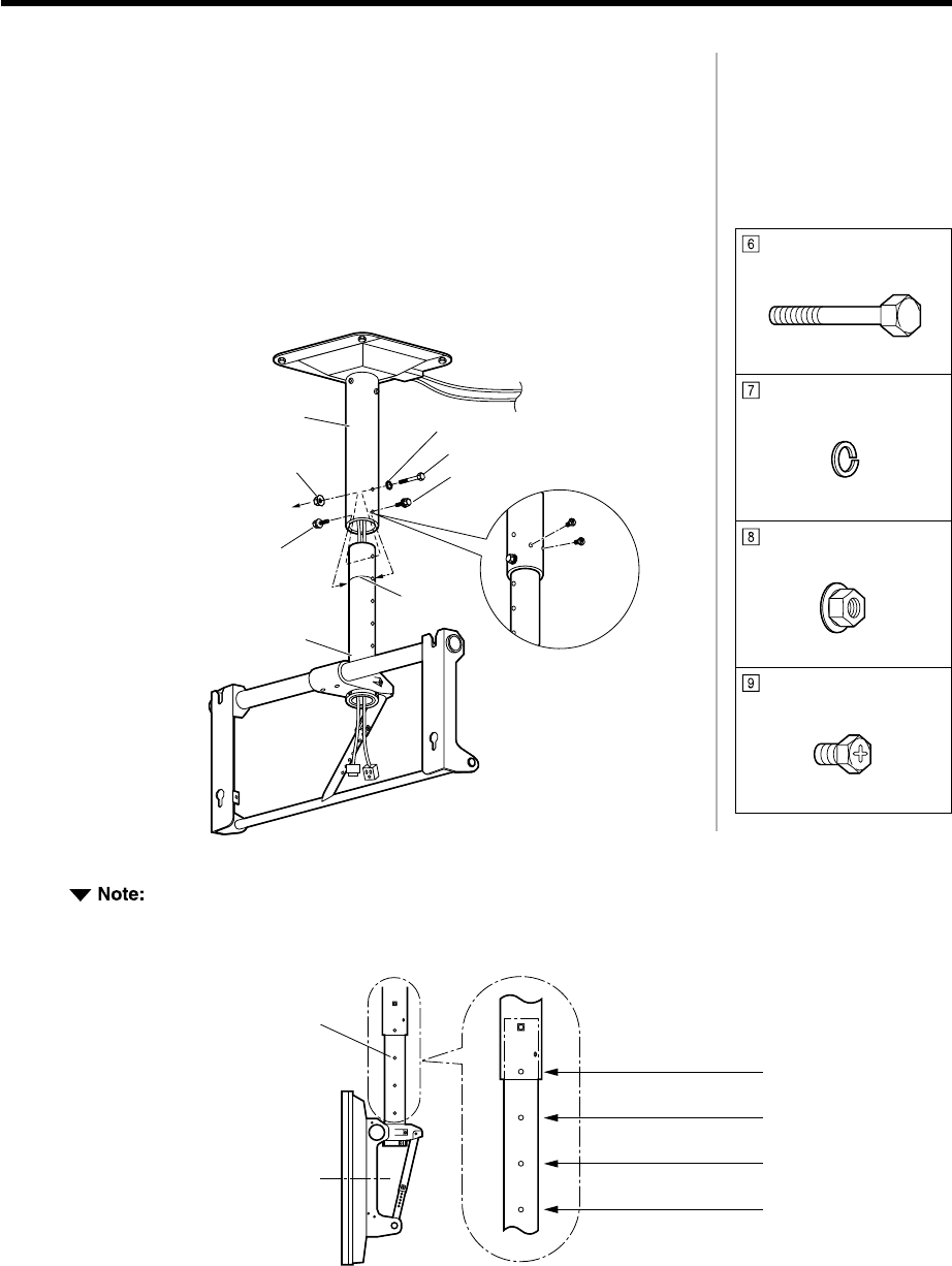
6-5
When adjusting the height, no more that 4 holes should be visible. (The white line should not show.)
Distance from
center of display
to ceiling ( in.)
Center of
display
Height adjustment
holes 1085mm (42 23/32)
985mm (38 25/32)
885mm (34 27/32)
785mm (30 29/32)
Washer pan nut
Spring washer
Fixing bolt (M8-100)
Fixing bolt
(M8-12)
Hidden
side
Ceiling unit
(upper section)
Fixing bolt (M8-12)
Fixing bolt (M8-12)
White line
(Example)
Ceiling unit
(lower section)
Attach the ceiling unit (lower section)
1) Match the height adjustment holes on the upper and lower sections
to the desired height and refasten in place with two M8 assembly
screws.
2) Insert the fixing bolt (M8-100) through the spring washer and then
insert it through the uppermost hole in the pipe. Fasten in place with
the washer pan nut (all included).
3) Tighten with two fixing bolts (M8-12, included) so that the lower
section does not move.
2
Fixing bolt (M8-100)
Spring washer
Washer pan nut (M8)
Fixing bolt (M8-12) x 2
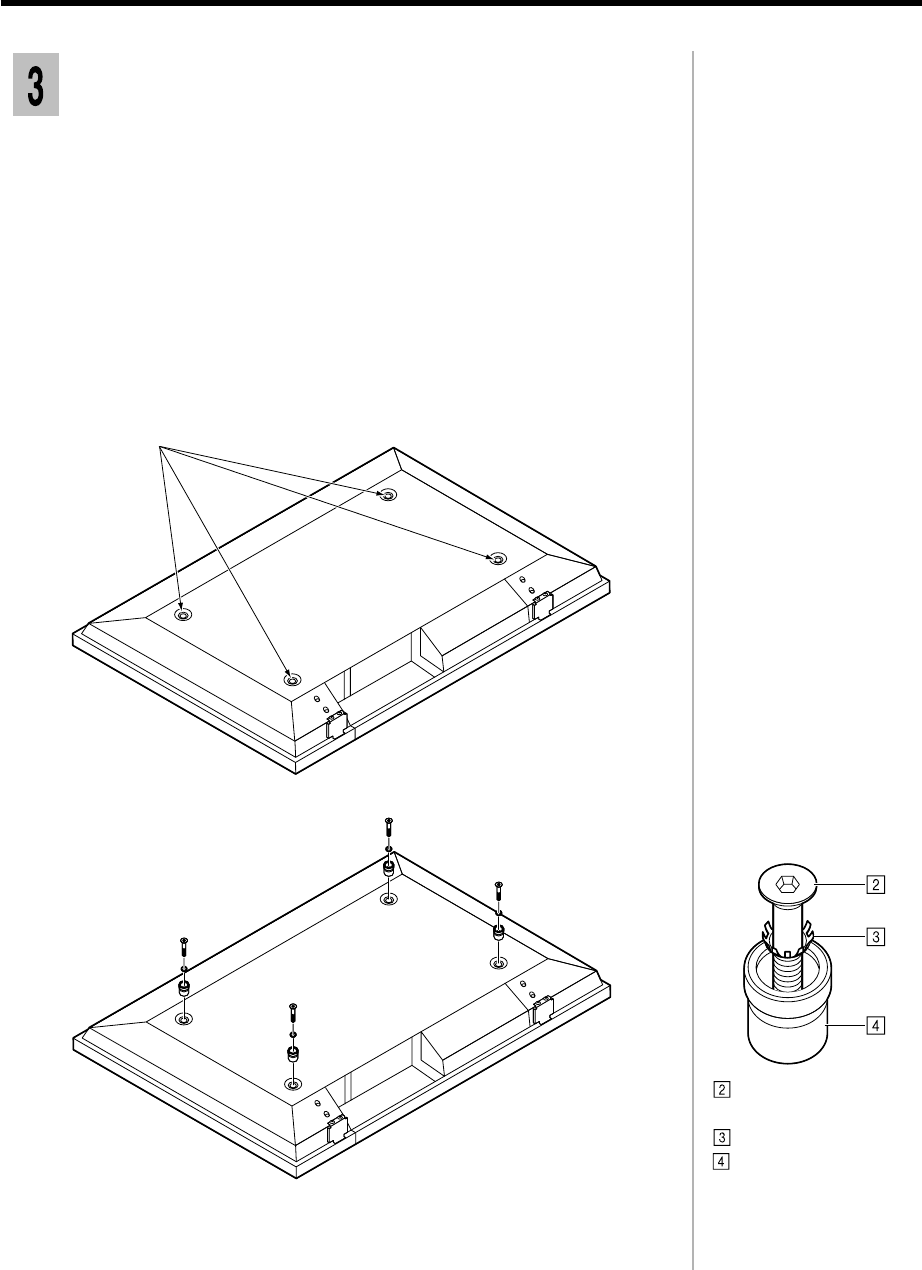
Prepare the display.
1
6-6
Quite los cuatro pernos.
Pan head bolt with
hex socket
Toothed pan washer
Insulating spacer
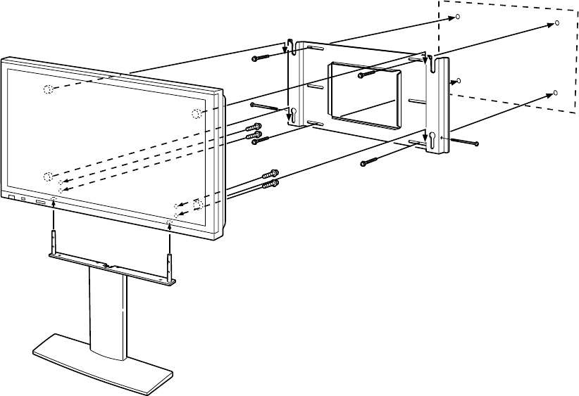
Install the insulating spacers in the display unit.
Lay the display with the screen facing down on a clean blanket or sheet and
follow the steps below.
1) Remove the four bolts from the display.
2) In each of the four bolt holes, insert a pan head bolt with hex socket
(M8-45), toothed pan washer and insulating spacer (four each, all
included). Insert as shown in the diagram on the left.
1
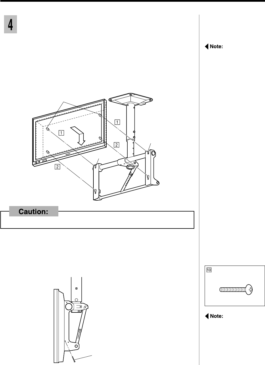
Mount the display in the ceiling unit.
Hook the display’s top insulating spacers in the ceiling unit by aligning
the display with the notches in the ceiling unit and sliding the display
downward.
1
Insert the bottom insulating spacers by lifting the display slightly, fitting
the bottom spacers into the holes, and then lowering the display.
2
When mounting the
display in the ceiling unit,
be sure the ceiling unit is
straight and not at an
angle.
6-7
Fixing screw (M5) 1 each
left and right sides
Do not lift the display too high. It may come unhooked from the unit.
Install the fixing screws
on the left and right to
prevent the display from
sliding out of the ceiling
unit.
Fix the display.
Install two fixing screws (M5, included) in the corresponding holes on the
ceiling unit (left and right).
3
Insulating spacer
Notch
Notch
Fixing screw (M5) x 2
6-8
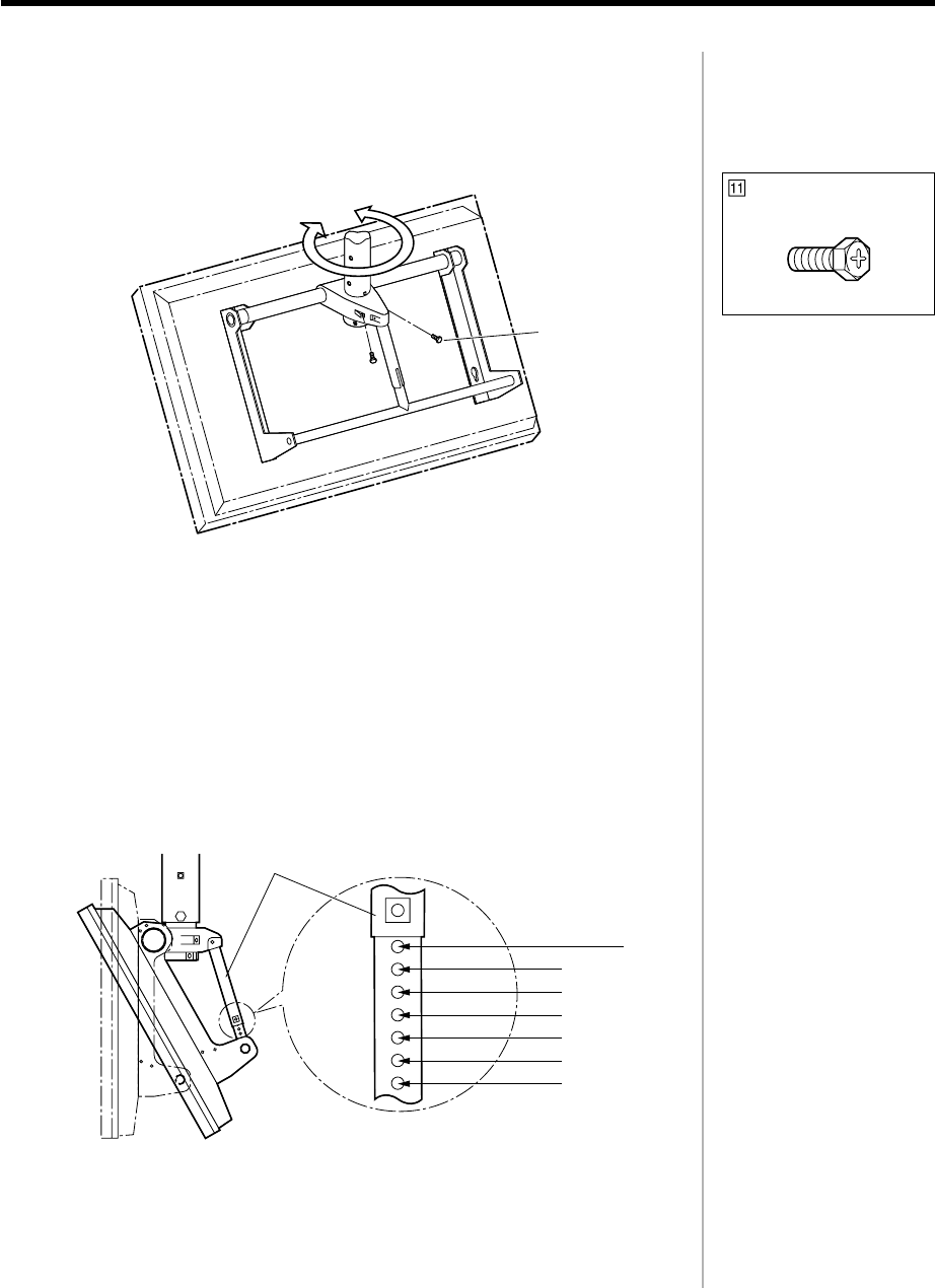
4Adjust the ceiling unit's direction.
Adjust the angle of the display and fix in place with two fixing bolts (M8-20,
included).
Connecting pipe Angle
adjustment
hole positions
0° (vertical)
5°
10°
15°
20°
25°
30°
5Adjust the ceiling unit's angle.
This ceiling unit can be placed in 7 angles from 0° to 30° in 5° increments.
The factory setting is 0°.
If you wish to change the angle, remove the angle adjustment screws from
the connecting pipe and adjust the angle adjustment holes to the desired
position. Then reinsert the screws.
Fixing bolt
(M8-20)
Fixing bolt (M8-20) x 2
6-9
6Gather the cables.
Gather the cables connected to the terminals on the back of the display and
fix in place with a cable tie.
Cable
Cable tie
Cable tie
Cable
Cable tie x 2
Removing the display unit
6-10
1) Lift the lower part of the display,
2) pull outward
3) and lift upward.
2
1Remove the two fixing screws (M5) at the left and right sides of the
ceiling unit.
Insulating
spacer
Fixing screw (M5)
3)
1)
2)
7-1
Assembly diagram
CONTENTS
Description ................................................... 7-2
Safety Precautions ....................................... 7-2
Instruction of the installation ...................... 7-3
1.Attach the sponges to the speakers ..................... 7-3
2.Attach the mounting brackets to the speakers ........ 7-3
3.Attach the speakers to the Wide Plasma Display .... 7-4
4.Secure the speakers in place ............................. 7-4
5.Connect the speaker cables ............................... 7-5
Speakers
TY-SP42PM3W
TY-SP42PWD3W
Description
Installation diagram
Units : mm (in.)
7-2
Safety Precautions
Do not suspend the speakers.
Personal injury may result if the speakers fall down. Take particular care to ensure the safety of children.
These speakers are for use with the Wide Plasma Display only.
If connecting them to some other amplifier, make sure that the maximum input to the speakers is within the rated
level (8 W). If the rated input level is exceeded, fire may result.
Make sure that all screws are tightened securely during installation.
Ensure that the installation is carried out property to prevent the speakers from becoming detached, and causing
possible personal injury.
100
610
89100
610
89
Left Speaker Right Speaker
Instruction of the installation
7-3
Attach the sponges to the speakers.
Sponges
For right For left
• Attach the sponges to the surfaces which are in contact with the Display.
• Clean the surfaces before attaching the sponges.
Attach the mounting brackets to the speakers.
Speaker (right) Speaker (Ieft)
Mounting brackets
(right)
Mounting brackets
(left)
Bracket mounting screws Bracket mounting screws
Mounting bracket
(left) x 2
Bracket mounting
Assembly screw (M4-10) x 8
Mounting bracket
(right) x 2
Sponge x 2
Attach the speakers to the Wide Plasma
Display.
• Insert the hooks on the top and bottom mounting brackets simultaneously
into the slots at the rear of the Wide Plasma Display, and then lower the
speaker into place.
• Attach the left speaker in the same way.
7-4
Hook
Rear of Wide Plasma Display
Slot
Slot
Secure the speakers in place.
• Adjust so that there is a uniform clearance between the Wide Plasma Display
and the speakers, and then securely tighten the bracket mounting screws.
• Secure the top and bottom mounting brackets by tightening the bracket
mounting screws.
• Secure the left speaker in the same way.
Bracket mounting
screw
Rear of Wide Plasma Display
Bracket mounting
Assembly screw (M4-10) x 8
7-5
1. If connecting to an external amplifier which exceeds the rated input for the speakers, lower the
amplifier volume to protect the speakers from damage. If any problems occur with speaker operation,
disconnect the mains lead of the amplifier and consult a qualified service technician.
2. Do not place the speakers in the following places:
• Places which are exposed to direct sunlight
• Near heaters or other heat sources
• Places with high humidity
3. This set is equipped with magnetic resistant speakers but be careful not to place them near the
CRT TV as it may cause color patches.
4. To clean the speakers, wipe them with a soft cloth. If they are extremely dirty, wipe them with a
cloth which has been soaked in a small amount of household detergent, and then wipe the dry
with a separate cloth.
• Do not use solvents such as alcohol or thinner.
• If using chemically-treated cloths, follow the instructions on the cloth packaging.
5. Remove the dust on the speaker net using a duster or a vacuum cleaner at low power. Since the
net is made of cloth, pushing too hard on it may damage the net.
Connect the speaker cables.
• After preparing the ends of the speaker cables, connect them as shown.
• Connect the speaker cable for the left speaker in the same way.
• The red cable is for the (+) side and the black cable is for the (-) side. Do not
connect the cables to the wrong sides.
Preparing the ends of the
speaker cables
While twisting
1.
Press down on the lever.
2. Insert
the cable.
3. Release the lever.
1. Push down the lever.
3. Return the lever to its
normal position.
2. Insert
the cable.
Speaker cable
(20 cm) x 2
When these speakers are attached to the plasma display, they will not
form a straight line but rather so that they slightly face inward, to produce
stable sounds.
Matsushita Electric Industrial Co., Ltd.
Central P.O. Box 288, Osaka 530-8692, Japan
