Panasonic WV CS574 User Manual To The 9dee2cb9 Bc05 4d3f B602 Fe757a931e4a
User Manual: Panasonic WV-CS574 to the manual
Open the PDF directly: View PDF ![]() .
.
Page Count: 60
- IMPORTANT SAFETY INSTRUCTIONS
- LIMITATION OF LIABILITY
- DISCLAIMER OF WARRANTY
- FEATURES
- ACCESSORIES
- OPTIONAL ACCESSORIES
- PRECAUTIONS
- CONSTRUCTION
- INSTALLATION PRECAUTIONS
- DIP SWITCH SETTINGS
- CAMERA INSTALLATION
- UNINSTALLING THE CAMERA
- CONNECTIONS
- RS485 SETUP
- USING THE SETUP MENU
- SETTING PROCEDURES
- SPECIFICATIONS
- SHORTCUTS
- TROUBLESHOOTING
Before attempting to connect or operate this product,
please read these instructions carefully and save this manual for future use.
FRANÇAIS ENGLISH
Color CCTV Camera
Operating Instructions
Model No. WV-CS574
-2-
WARNING: To prevent fire or electric shock hazard, do not expose this appliance to rain or moisture. The apparatus shall not be exposed
to dripping or splashing and that no objects filled with liquids, such as vases, shall be placed on the apparatus.
The serial number of this product may be found on the top
of the unit.
You should note the serial number of this unit in the space
provided and retain this book as a permanent record of your
purchase to aid identification in the event of theft.
Model No. WV-CS574
Serial No.
NOTE: This equipment has been tested and found to comply
with the limits for a Class A digital device, pursuant to Part
15 of the FCC Rules. These limits are designed to provide
reasonable protection against harmful interference when the
equipment is operated in a commercial environment. This
equipment generates, uses, and can radiate radio frequency
energy and, if not installed and used in accordance with the
instruction manual, may cause harmful interference to radio
communications.
Operation of this equipment in a residential area is likely to
cause harmful interference in which case the user will be
required to correct the interference at his own expense.
FCC Caution: To assure continued compliance, (example -
use only shielded interface cables when connecting to
computer or peripheral devices). Any changes or modifi-
cations not expressly approved by the party responsible for
compliance could void the user’s authority to operate this
equipment.
For U.S.A
This Class A digital apparatus complies with Canadian
ICES-003.
For Canada
The lightning flash with arrowhead
symbol, within an equilateral triangle, is
intended to alert the user to the
presence of uninsulated "dangerous
voltage" within the product's enclosure
that may be of sufficient magnitude to
constitute a risk of electric shock to
persons.
The exclamation point within an
equilateral triangle is intended to alert
the user to the presence of important
operating and maintenance (servicing)
instructions in the literature accompa-
nying the appliance.
SA 1965
SA 1966
CAUTION: TO REDUCE THE RISK OF ELECTRIC SHOCK,
DO NOT REMOVE COVER (OR BACK).
NO USER-SERVICEABLE PARTS INSIDE.
REFER SERVICING TO QUALIFIED SERVICE PERSONNEL.
CAUTION
RISK OF ELECTRIC SHOCK
DO NOT OPEN
ENGLISH VERSION

-3-
IMPORTANT SAFETY INSTRUCTIONS
1) Read these instructions.
2) Keep these instructions.
3) Heed all warnings.
4) Follow all instructions.
5) Do not use this apparatus near water.
6) Clean only with dry cloth.
7) Do not block any ventilation openings. Install in accordance with the manufacturer's instructions.
8) Do not use near any heat sources such as radiators, heat registers, stoves, or other apparatus (including ampli-
fiers) that produce heat.
9) Do not defeat the safety purpose of the polarized or grounding-type plug. A polarized plug has two blades with
one wider than the other. A grounding-type plug has two blades and a third grounding prong. The wide blade or
the third prong are provided for your safety. If the provided plug does not fit into your outlet, consult an electrician
for replacement of the obsolete outlet.
10
)Protect the power cord from being walked on or pinched particularly at plugs, convenience receptacles and the
points where they exit from the apparatus.
11
)Only use attachments/accessories specified by the manufacturer.
12
)Use only with the cart, stand, tripod, bracket, or table specified by the manufacturer, or sold with the apparatus.
When a cart is used, use caution when moving the cart/apparatus combination to avoid injury from tip-overs.
13
)Unplug this apparatus during lightning storms or when unused for long periods of time.
14
)Refer all servicing to qualified service personnel. Servicing is required when the apparatus has been damaged in
any way, such as power-supply cord or plug is damaged, liquid has been spilled or objects fallen into the appara-
tus, the apparatus has been exposed to rain or moisture, does not operate normally, or has been dropped.
S3125A
ENGLISH

-4-
LIMITATION OF LIABILITY
THIS PUBLICATION IS PROVIDED "AS IS" WITHOUT WARRANTY OF ANY KIND, EITHER EXPRESS OR IMPLIED,
INCLUDING BUT NOT LIMITED TO, THE IMPLIED WARRANTIES OF MERCHANTABILITY, FITNESS FOR ANY PAR-
TICULAR PURPOSE, OR NON-INFRINGEMENT OF THE THIRD PARTY'S RIGHT.
THIS PUBLICATION COULD INCLUDE TECHNICAL INACCURACIES OR TYPOGRAPHICAL ERRORS. CHANGES
ARE ADDED TO THE INFORMATION HEREIN, AT ANY TIME, FOR THE IMPROVEMENTS OF THIS PUBLICATION
AND/OR THE CORRESPONDING PRODUCT(S).
IN NO EVENT SHALL MATSUSHITA ELECTRIC INDUSTRIAL CO., LTD. BE LIABLE TO ANY PARTY OR ANY PER-
SON, EXCEPT FOR REPLACEMENT OR REASONABLE MAINTENANCE OF THE PRODUCT, FOR THE CASES,
INCLUDING BUT NOT LIMITED TO BELOW:
(1) ANY DAMAGE AND LOSS, INCLUDING WITHOUT LIMITATION, DIRECT OR INDIRECT, SPECIAL, CONSEQUEN-
TIAL OR EXEMPLARY, ARISING OUT OF OR RELATING TO THE PRODUCT;
(2) PERSONAL INJURY OR ANY DAMAGE CAUSED BY INAPPROPRIATE USE OR NEGLIGENT OPERATION OF THE
USER;
(3) UNAUTHORIZED DISASSEMBLE, REPAIR OR MODIFICATION OF THE PRODUCT BY THE USER;
(4) INCONVENIENCE OR ANY LOSS ARISING WHEN IMAGES ARE NOT DISPLAYED, DUE TO ANY REASON OR
CAUSE INCLUDING ANY FAILURE OR PROBLEM OF THE PRODUCT;
(5) ANY PROBLEM, CONSEQUENTIAL INCONVENIENCE, OR LOSS OR DAMAGE, ARISING OUT OF THE SYSTEM
COMBINED BY THE DEVICES OF THIRD PARTY.
(6) ANY CLAIM OR ACTION FOR DAMAGES, BROUGHT BY ANY PERSON OR ORGANIZATION BEING PHOTO-
GENIC SUBJECT, DUE TO VIOLATION OF PRIVACY WITH THE RESULT OF THAT SURVEILLANCE-CAMERA'S
PICTURE, INCLUDING SAVED DATA, FOR SOME REASON, BECOMES PUBLIC OR IS USED FOR THE PURPOSE
OTHER THAN SURVEILLANCE.
(7) ANY PROBLEM, CONSEQUENTIAL INCONVENIENCE, ANY LOSS OR DAMAGE, ARISING OUT OF THE IMPROP-
ER DETECTION OR SLIP-UP IN DETECTION BY VMD (VIDEO MOTION DETECTOR) FUNCTION OF THE PROD-
UCT.
DISCLAIMER OF WARRANTY
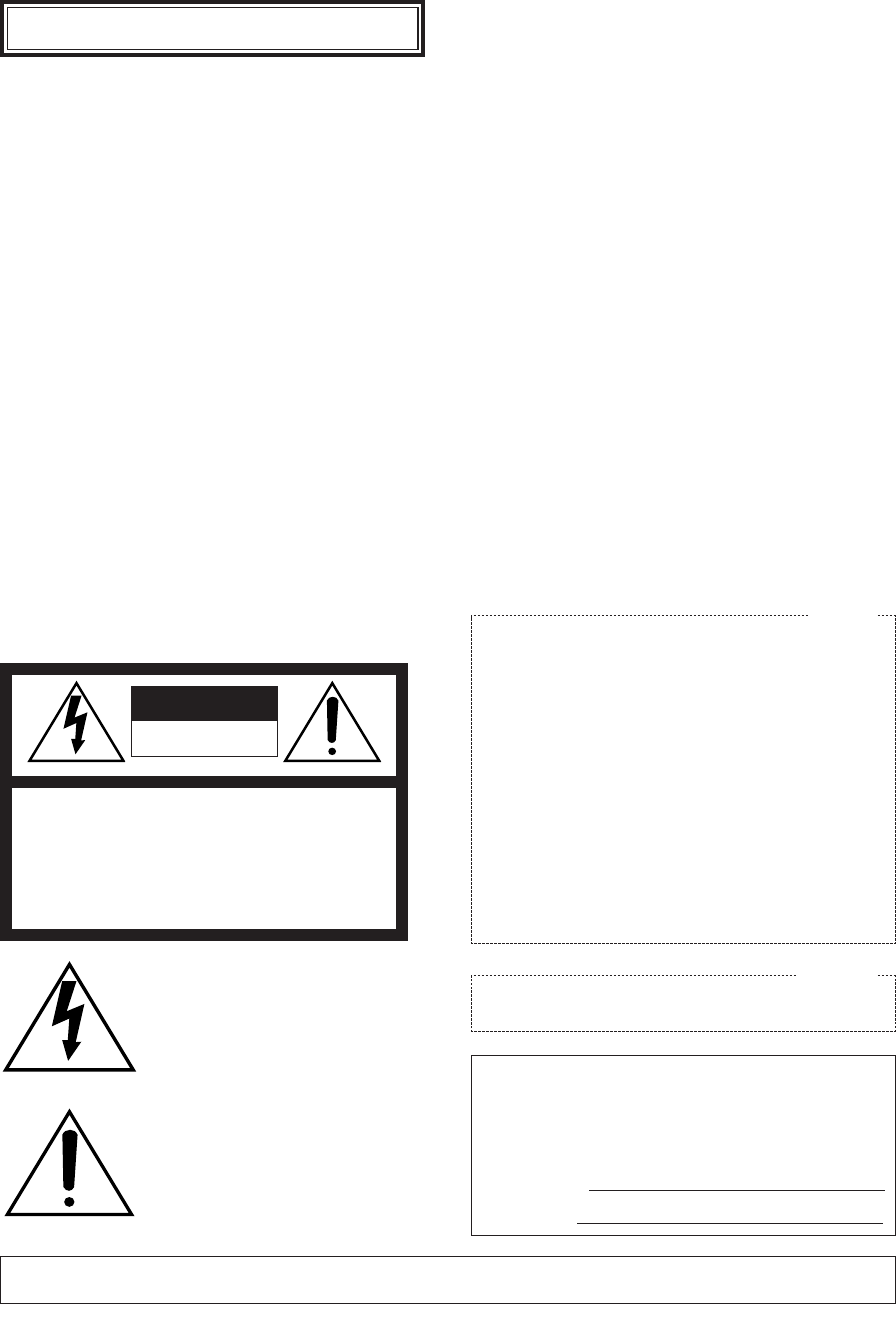
Digital Flip Operation
q Tilting
downwards w The picture is
flipped when the
camera is pointing
straight down
(at around 135°).
e Tilting upwards.
Digital flip is performed only when the system controller joystick is
held downwards.
-5-
This Color CCTV Camera is a video surveillance device
that incorporates a 1/4-type {1/4"} CCD, a 22x zoom
lens, preset and pan and tilt capabilities in a dome con-
figuration. It also has the following features.
■New DSP for High Sensitivity
A new noise reduction system lowers minimum illumi-
nance to 1.0 lx {0.1 footcandle} in the color mode.
■Digital Flip
Normally, a camera needs to stop when it points
straight down during a tilt operation. With digital flip,
however, the camera is able to tilt from 0° to 180° in a
single motion. This makes it possible to track subjects
passing directly under the camera more smoothly.
■Privacy Zone Function
The privacy zone function makes it possible to mask
specific areas of the scene from view.
■Patrol Function
The patrol function remembers manual camera move-
ment routines for automatic playback when they are
needed. For example, you can teach the camera the
movements of the people you want to monitor, by
replaying the stored parameters complicated move-
ments are done automatically.
■Camera Position Memory
The system can be configured with up to 32 camera
positions. A particular camera position can be selected
and viewed by entering the applicable preset number
on the system controller 10-key pad.
■Motion Detection
The system can be configured so any motion on the
monitor screen during surveillance causes output of an
alarm signal.
This function can be used to structure a system with a
VCR that records images of nighttime intruders.
FEATURES
ACCESSORIES
Operating Instructions (this manual) ...................... 1 pc.
The following items are for installation.
Decorative Cover ................................................... 1 pc.
Dust Protection Sheet ............................................. 1 pc.
8P Alarm Cable ...................................................... 1 pc.
4P Alarm Cable ...................................................... 1 pc.
Connector for 24 V AC ........................................... 1 pc.
OPTIONAL ACCESSORIES
Dome Cover (approx. 60 % transparency, smoked type) .......... WV-CS2S
Dome Cover (approx. 50 % transparency, smoked type) .......... WV-CS2SH
Dome Cover (approx. 70 % transparency, metal type) .............. WV-CS2M
Ceiling Mount Bracket ................................................................. WV-Q117
Wall Mount Bracket ..................................................................... WV-Q118

-6-
PRECAUTIONS
■Do not attempt to disassemble the camera.
To prevent electric shock, do not remove screws or
covers.
There are no user-serviceable parts inside.
Ask qualified service personnel for servicing.
■Handle the camera with care.
Do not misuse the camera. Avoid striking, shaking, etc.
The camera could be damaged by improper handling
or storage.
■Do not expose the camera to rain or moisture, nor
try to operate it in wet areas.
This product is designed for indoor use or locations
where it is protected from rain and moisture.
Turn the power off immediately and ask qualified serv-
ice personnel for servicing.
Moisture can damage the camera and also create the
danger of electric shock.
■Do not use strong or abrasive detergents when
cleaning the camera body.
Use a dry cloth to clean the camera when it is dirty.
When the dirt is hard to remove, use a mild detergent
and wipe gently. Care should be taken not to scratch
the dome cover when wiping it.
Afterwards, wipe off the remaining detergent with a dry
cloth.
■Never aim the camera at the sun.
Whether or not the camera is in use , never aim it at the
sun or other extremely bright objects. Otherwise,
blooming or smear may be caused.
■Do not point the camera at a strong light source.
Intense light such as that produced by a spotlight con-
centrated on one part of the screen can cause bloom-
ing (rainbow around the strong light) or smearing (verti-
cal stripes above and below the strong light).
■Do not install this camera upside down.
This camera is designed for mounting on the ceiling or
wall. Using this camera installed upside down, for
example, mounted on the floor, may cause malfunction.
■Do not operate the camera beyond the specified
temperature, humidity or power source ratings.
Do not use the camera in an extreme environment
where high temperature or high humidity exists. Do not
place the camera near heat sources such as radiators,
stoves or other units that produce heat.
Use the camera under conditions where tempera-ture is
between –10°C - +50°C {14°F - 122°F}, preferably
+40°C {104°F}, and humidity is below 90 %.
The input power source is 24 V AC 60 Hz.
■Do not install the camera near the air outlet of an
air conditioner.
The lens may become cloudy due to condensation if
the camera is used under the following conditions.
•Rapid temperature fluctuations by switching the air
conditioner on and off.
•Rapid temperature fluctuations due to frequent door
opening and closing.
•Use in an environment where eyeglasses become
foggy.
•Use in a room filled with cigarette smoke or dust.
If the lens becomes cloudy due to condensation,
remove the dome cover and wipe all moist surfaces
with a soft cloth.
•Avoid use of this camera in a food preparation area
and other locations where there are large amounts
of steam vapor and oil.
■Consumables
Parts having contacts such as the lens-drive motors,
cooling fan motor and slip-rings inside the camera are
subject to wear with time. Please ask the nearest serv-
ice center about replacement and maintenance of such
parts.
■Do not aim the camera at the same object for a
long time.
Burn-in of an image may be caused on the fluorescent
screen of CRT.
■Self-diagnosis Function
If the camera continues operating abnormally for 30
seconds or more due to such an accident as external
noise, the camera will automatically reset its power. In
the case it happens frequently, check if there would be
any environmental cause.
Smearing
Bright Subject
Blooming

-7-
■About the Camera Cleaning Function
Prolonged use can lead to noise on the monitor and
divergence of preset positions.
If such conditions persist even after you perform cam-
era cleaning (page 41), use the special setup menu to
execute the "REFRESH" operation (page 50).
If you are using a matrix switcher with a camera clean-
ing function (WJ-SX550C), configure the matrix switch-
er Auto Cleaning settings so cleaning is performed
once a day.
■Downloading (saving) or uploading (recovering)
camera preset data
When downloading or uploading camera preset data,
aim the camera at static objects such as a wall without
moving the camera as much as possible.

-8-
CONTENTS
IMPORTANT SAFETY INSTRUCTIONS ............................................................................ 3
LIMITATION OF LIABILITY ............................................................................................... 4
DISCLAIMER OF WARRANTY .......................................................................................... 4
FEATURES ........................................................................................................................ 5
■New DSP for High Sensitivity ..................................................................................... 5
■Digital Flip .................................................................................................................. 5
■Privacy Zone Function ............................................................................................... 5
■Patrol Function ..............................................................................................................5
■Camera Position Memory .......................................................................................... 5
■Motion Detection ........................................................................................................ 5
ACCESORIES ................................................................................................................... 5
OPTIONAL ACCESORIES ................................................................................................ 5
PRECAUTIONS ................................................................................................................. 6
CONSTRUCTION ............................................................................................................. 9
INSTALLATION PRECAUTIONS ....................................................................................... 10
DIP SWITCH SETTINGS ................................................................................................... 11
■Communication Parameters (DIP Switch 2) .............................................................. 11
■Unit Number (DIP Switch 1) ....................................................................................... 12
■RS485 Communication Parameters (DIP Switch 1) ................................................... 13
CAMERA INSTALLATION ................................................................................................. 14
■Preparing the Camera and Decorative Cover for Side Cable Exit ............................ 14
■Installing the Camera ................................................................................................. 14
UNINSTALLING THE CAMERA ........................................................................................ 16
■Uninstalling the Camera ............................................................................................ 16
CONNECTIONS ................................................................................................................ 17
RS485 SETUP ................................................................................................................... 19
USING THE SETUP MENU ............................................................................................... 20
■Setup Menu ............................................................................................................... 20
■Setup Menu Description ............................................................................................ 22
SETTING PROCEDURES .................................................................................................. 26
■Menu Display ............................................................................................................. 26
■Preset Menu ............................................................................................................... 26
■Deleting Preset Positions ........................................................................................... 31
■Home Position Setting (HOME POSITION) ................................................................ 31
■Self Return Setting (SELF RETURN) .......................................................................... 31
■Auto Mode Selection (AUTO MODE) ......................................................................... 32
■Auto Pan Key Setting (AUTO PAN KEY) .................................................................... 33
■Digital Flip Setting (DIGITAL FLIP) ............................................................................ 34
■Special 1 Menu Setting (SPECIAL 1) ......................................................................... 35
■Camera Setting .......................................................................................................... 42
SPECIFICATIONS.............................................................................................................. 52
SHORTCUTS .................................................................................................................... 54
TROUBLESHOOTING ...................................................................................................... 56
-9-
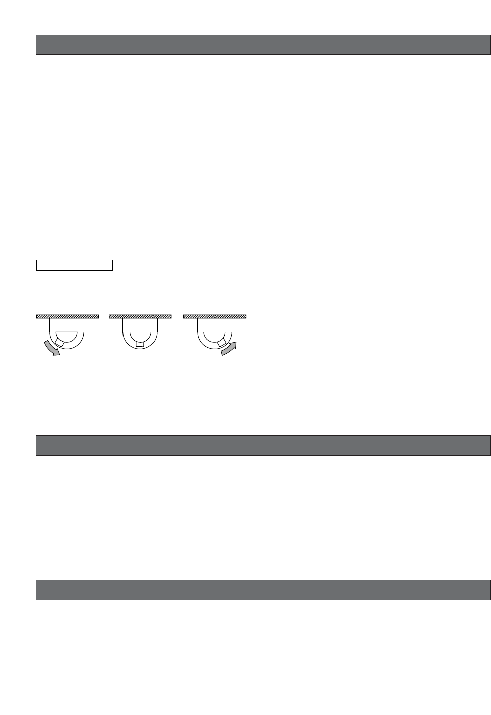
CONSTRUCTION
Ensuring Trouble-free Operation
•This camera uses a "slip ring" for transmission of electrical power and signals. A dirty slip ring can cause deterio-
ration of picture quality during panning and generation of noise.
In order to ensure trouble-free camera operation, make sure that the cleaning function (page 41) is turned on.
•If cleaning the slip ring does not eliminate poor picture quality and noise, it could mean that the slip ring has
reached the end of its service life. Contact a qualified service person or system installer to have it replaced.
w
e
r
t
q
yu
o
i
!0
qAlarm Input Connector
wAlarm Output Connector
eVideo Output Connector
rData Port
tPower Cable
yCamera Mounting Base
uPanning Start Point
iFall Prevention Wire
oDecoration Cover
!0 Dome Cover
-10-
INSTALLATION PRECAUTIONS
Warning:
Discuss the installation location for the camera with
your retailer, and select a place that is strong
enough for the installation. If you install the camera
on a ceiling or wall, except for accidents caused by
fault in the camera, Panasonic holds absolutely no
responsibility for accidents caused by the camera
falling due to unsuitable installation. Take sufficient
care when installing the camera. If the installation is
not strong enough, be sure to sufficiently reinforce
the location and check that it is safe.
Warning:
Always request installation work from a qualified
service person or system installer. Lack of technical
knowledge creates the risk of fire, electric shock,
personal injury, and material damage.
■Camera Installation Location
•Install the camera on a ceiling (concrete, etc.) at a
location that is sufficiently strong to support it.
•For ceiling mounting, use the optionally available
WV-Q117 Ceiling Mount Bracket.
•For wall mounting, use the optionally available WV-
Q118 Wall Mount Bracket.
■This camera is an indoor camera. It is not
designed for outdoor use.
■This camera is designed for use in a hanging con-
figuration only. Using it in an upright or inclined
configuration can cause malfunction and shorten
the life of the camera.
■Install the camera in a horizontal configuration,
with the dome pointed downwards.
■Never install or use the camera in the following
locations.
•Areas directly exposed to rain and water
•Near a swimming pool or other areas where chemi-
cals are used
•Food preparation areas and other locations where
there are large amounts of steam vapor and oil, in
flammable atmospheres, other special environments
•Areas where radiation, X-rays, strong electric waves,
or magnetism is generated
•At sea, in coastal areas, or in areas where corrosive
gas is being generated
•Areas outside of the allowable ambient operating
temperature range (–10°C to +50°C {14°F to
122°F})
•In a motor vehicle, on a boat, or other areas subject
to strong vibration (This camera is not designed for
use in a vehicle.)
•Near an air conditioner outlet, near a door that
opens up to the outdoors, or any other area subject-
ed to temperature extremes (Such conditions can
cause clouding and condensation formation on the
dome cover.)
■Wiring the Camera
•If you need to connect a ground, be sure to do it
before you connect the main power plug. Also,
when removing the ground, be sure to disconnect
the main power plug.
•The camera does not have a power switch, so it
turns on as soon as the power cord is plugged into
a power outlet. During the electrical work, configure
the power supply to the camera so it can be turned
on and off. A self-cleaning function is activated
(PAN/TILT/ZOOM/FOCUS) when the camera is
turned on.
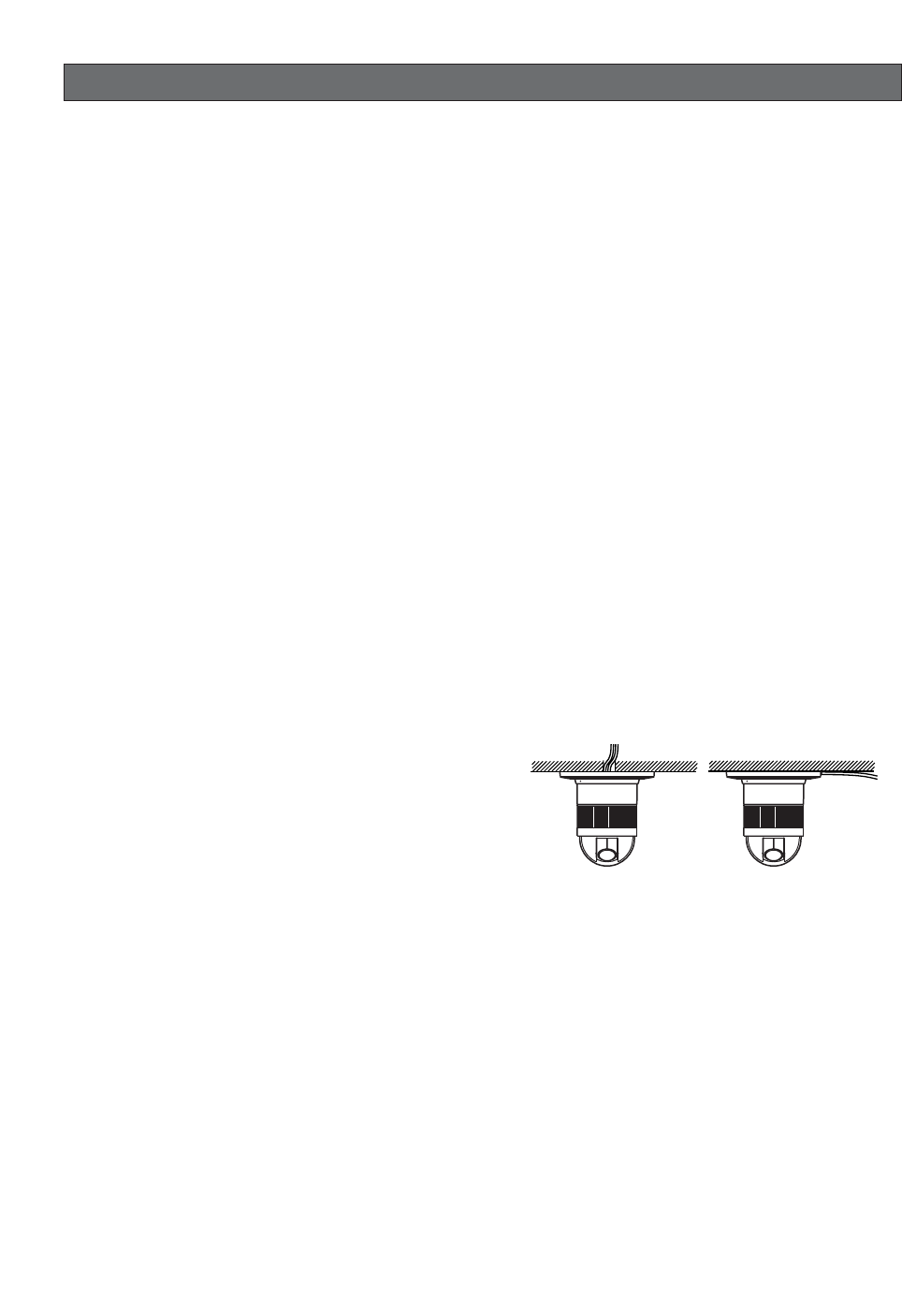
■When wiring the camera, its cables (power, video
output, RS485, alarm in, alarm out) can exit out
the side or the top of the camera.
•When using the top cable exit configuration, drill a
hole in the ceiling to allow passage of the cables.
(See step 3 on page 15.)
•When using the side cable exit configuration, pre-
pare the cutout in the die cast case and decorative
cover. (See "Preparing the Camera and Decorative
Cover for Side Cable Exit" on page 14.)
■Noise interference considerations
When using a power line that is greater than 120 V AC
and wiring that is longer than 1 meter, wiring should be
performed using a separate metal conduit. (The metal
conduit must be earth grounded.)
■Screws should be ordered separately.
The camera does not come with screws. Make sure that
the materials and structure of the installation location is
strong enough to support the total weight of the cam-
era.
-11-
Important:
Before setting up the camera for a configuration
where the camera's RS485 data port is used for
camera control (pan, tilt, etc.) by the system con-
troller, the camera's DIP switches must be con-
figured to specify the unit number and communi-
cation parameters. (This page)
If DIP switch setting is not performed, the system
controller control will not be possible and cam-
era setup will have to be performed again. Be
sure to check the DIP switch settings before set-
ting up the camera.
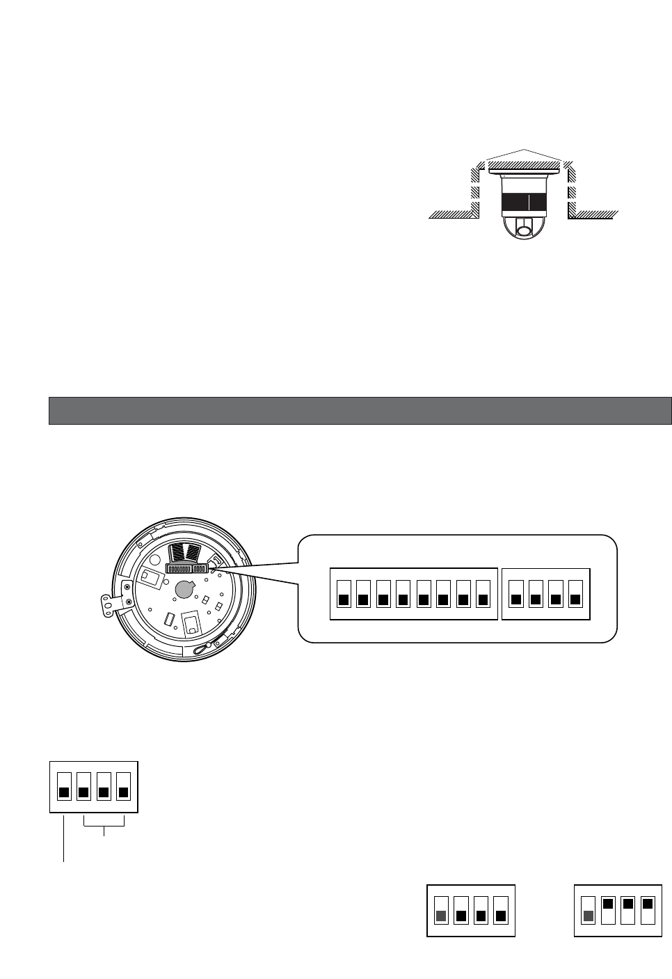
■Heat radiation
The surface of the camera radiates heat. Ventilation
holes should be provided when installing the camera in
an enclosed ceiling or confined location where heat can
build up.
■Beware of high humidity.
If the camera is installed when humidity is very high,
moisture may collect in the camera and cause the
dome to become foggy. If the dome becomes foggy,
remove it when the humidity is low and eliminate the
moisture inside the camera, and then replace the
dome. (page 9)
Ventilation holes
DIP SWITCH SETTINGS
In a configuration where the camera's RS485 data port is used for camera control (pan, tilt, etc.) by the system con-
troller, the camera's DIP switches must be configured to specify the unit number and communication parameters.
The camera mounting base needs to be removed to access the DIP switches. See steps 1 to 3 on page 16 for infor-
mation about how to remove the camera mounting base.
■Communication Parameters (DIP Switch 2)
The factory default settings of these DIP switches are all OFF.
Switch 1: Terminator (Internal Termination Resistance)
Set it to ON in the following situations.
When only one camera is connected.
When only one camera is connected via a daisy chain over a long distance.
Switches 2 through 4: Communication Parameters
This setting toggles between 2-line and 4-line communication.
Use these switches to select the communication protocol being
used.
1234
ON
Terminator
Communication
Parameters
1234
ON
4-line Communication
1234
ON
2-line Communication
1234
ON
1234
ON
5678
DIP Switch 1 DIP Switch 2
-12-
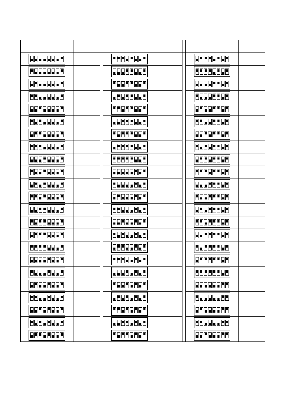
■Unit Number (DIP Switch 1)
The factory default settings of these DIP switches are all OFF. (Coaxial Multiplex System)
1234
ON
5678
DIP Switch 1 Unit
Number
1234
ON
5678
1234
ON
5678
1234
ON
5678
1234
ON
5678
1234
ON
5678
1234
ON
5678
1234
ON
5678
1234
ON
5678
1234
ON
5678
1234
ON
5678
1234
ON
5678
1234
ON
5678
1234
ON
5678
1234
ON
5678
1234
ON
5678
1234
ON
5678
1234
ON
5678
1234
ON
5678
1234
ON
5678
1234
ON
5678
1234
ON
5678
1234
ON
5678
1234
ON
5678
1234
ON
5678
1234
ON
5678
1234
ON
5678
1234
ON
5678
1234
ON
5678
1234
ON
5678
1234
ON
5678
1234
ON
5678
DIP Switch 1 Unit
Number DIP Switch 1 Unit
Number
1 ~ 96 *
1
2
3
4
5
6
7
8
9
10
11
12
13
14
15
16
17
18
19
20
21
22
23
24
25
26
27
28
29
30
31
32
33
34
35
36
37
38
39
40
41
42
43
44
45
46
47
48
49
50
51
52
53
54
55
56
57
58
59
60
61
62
63
64
65
66
67
68
1234
ON
5678
1234
ON
5678
1234
ON
5678
1234
ON
5678
1234
ON
5678
1234
ON
5678
1234
ON
5678
1234
ON
5678
1234
ON
5678
1234
ON
5678
1234
ON
5678
1234
ON
5678
1234
ON
5678
1234
ON
5678
1234
ON
5678
1234
ON
5678
1234
ON
5678
1234
ON
5678
1234
ON
5678
1234
ON
5678
1234
ON
5678
1234
ON
5678
1234
ON
5678
1234
ON
5678
1234
ON
5678
1234
ON
5678
1234
ON
5678
1234
ON
5678
1234
ON
5678
1234
ON
5678
1234
ON
5678
1234
ON
5678
1234
ON
5678
1234
ON
5678
1234
ON
5678
1234
ON
5678
1234
ON
5678
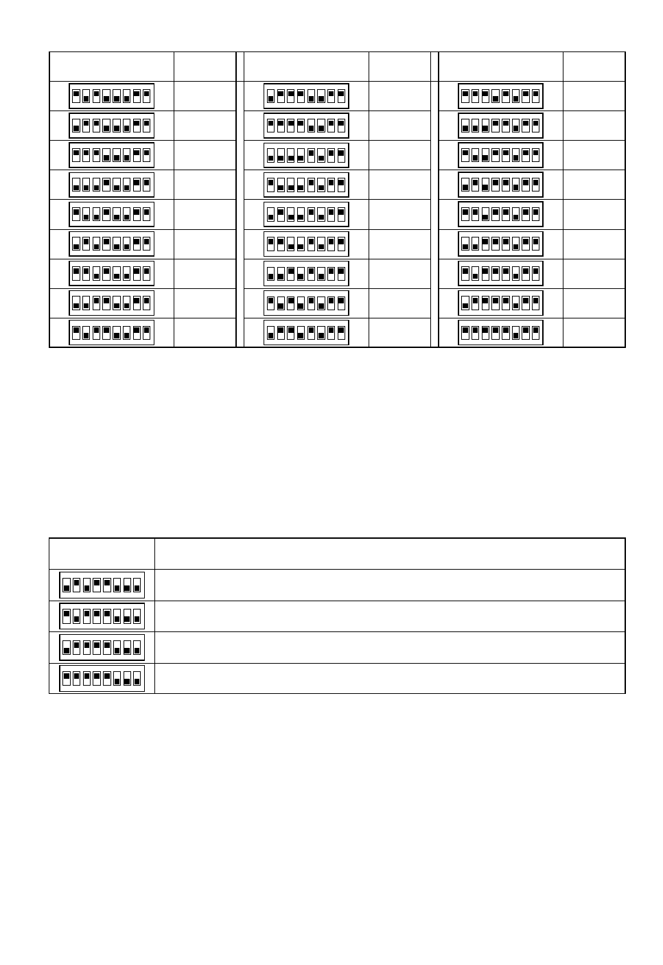
-13-
1234
ON
5678
DIP Switch 1 Unit
Number
1234
ON
5678
1234
ON
5678
1234
ON
5678
1234
ON
5678
1234
ON
5678
1234
ON
5678
1234
ON
5678
1234
ON
5678
1234
ON
5678
1234
ON
5678
1234
ON
5678
1234
ON
5678
1234
ON
5678
1234
ON
5678
1234
ON
5678
1234
ON
5678
1234
ON
5678
DIP Switch 1 Unit
Number DIP Switch 1 Unit
Number
69
70
71
72
73
74
75
76
77
78
79
80
81
82
83
84
85
86
87
88
89
90
91
92
93
94
95
1234
ON
5678
1234
ON
5678
1234
ON
5678
1234
ON
5678
1234
ON
5678
1234
ON
5678
1234
ON
5678
1234
ON
5678
1234
ON
5678
*When using the Unit Number 1 to 96 setting, the unit number setting needs to be configured using the RS485 SET
UP menu. For details about configuring this setting, see step 2 and page 19.
*Turning on power when this setting is selected causes the RS485 SET UP menu to appear during the initialization
routine.
■RS485 Communication Parameters (DIP Switch 1)
Configuring DIP Switch 1 as shown below resets communication parameters to their factory default settings. You can
then change the settings as desired.
Perform the following steps to use this setting.
(1) Turn off the camera and use DIP Switch 1 to configure RS485 communication parameters as shown above.
(2) Turn on the camera.
This applies the setting you configured in step (1).
(3) Turn off the camera, use DIP Switch 1 to set the unit number (pages 12 and 13), and then turn the camera back on
again.
1234
ON
5678
DIP Switch 1 Setting Description
1234
ON
5678
1234
ON
5678
1234
ON
5678
This setting resets communication parameters to the factory default settings.
BAUD RATE : 19 200 bit/s, DATA BIT : 8 bit, PARITY CHECK : NONE, STOP BIT : 1 bit
BAUD RATE : 9 600 bit/s, DATA BIT : 8 bit, PARITY CHECK : NONE, STOP BIT : 1 bit
BAUD RATE : 4 800 bit/s, DATA BIT : 8 bit, PARITY CHECK : NONE, STOP BIT : 1 bit
ON
-14-
CAMERA INSTALLATION
■Preparing the Camera and
Decorative Cover for Side Cable
Exit
The camera and decorative cover should be prepared
as shown below when mounting the camera on a ceil-
ing or wall with its cables (power, video output, RS485,
alarm in, alarm out) exiting from the side.
The camera mounting base needs to be removed in
order to prepare the camera. See steps 1 and 2 below
for information about how to remove the camera mount-
ing base.
Cutout in Diecast Case
Cutout in Decoration Cover
■Installing the Camera
•Select an installation location that is strong enough
to withstand the total weight of the camera. Installing
the camera at a location that is too weak can cause
it to fall.
•Remove the protective sheet after the installation
work is complete.
•If you are using an optional bracket to install the
camera, install the bracket in accordance with the
instructions that come with it.
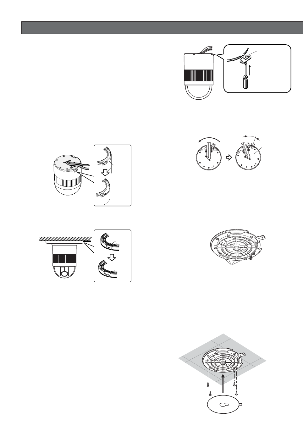
1. Remove the fixing screw (M3 ×6) that secures the
camera to the mounting base.
Put the screw in a place where it will not become
lost.
2. Rotate the camera base unit in the direction indicat-
ed by the arrow and remove it.
3. Using the camera mounting base as a template,
mark the locations of the four mounting holes on the
ceiling.
If you are using the top cable exit configuration,
mark the location of the cable hole on the ceiling
and drill the hole.
4. Affix the camera mounting base onto the ceiling.
Use screws (M4) at the locations you marked above
to secure the mounting base to the ceiling.
If you do not plan to install the camera right away,
affix the dust protection sheet that comes with the
camera to the mounting base to keep dust off of it.
After loosening
the screw, press
upwards on the
camera and then
remove it.
Fixing screw
Rotate Pull the camera
mounting base
up to remove it.
15°
Mark here
Dust Protection Sheet
(comes with camera)
Screws
(M4, available separately)
Cut out
Cut out
-15-
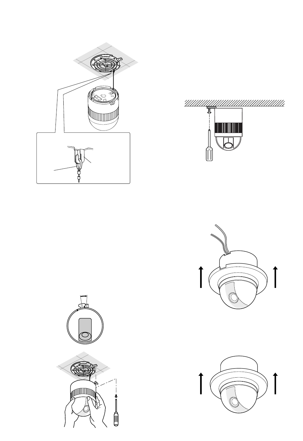
5. Hook the fall prevention wire on the camera mount-
ing base.
Cautions:
•Use the supplied dust protection sheet if the camera
mounting base is liable to be exposed to a dusty
atmosphere. Remove the cover from the dust pro-
tection sheet, then stick the sheet on the camera
mounting base.
•Remove the sheet before mounting the camera on
the base.
•While the camera is separated from the base, keep
the camera in the supplied polyethylene sack.
6. Mount the camera on the camera mounting base
and rotate the camera clockwise.
7. Tighten the fixing screw M3 (provided).
Notes:
(1) Tighten the camera fixing screw with a screw-
driver.
(2) Follow the instructions given here to ensure
that the camera and camera mounting base
are installed safely.
(3) When removing the camera from the camera
mounting base, loosen and press up the
camera fixing screw (M3) with a screwdriver.
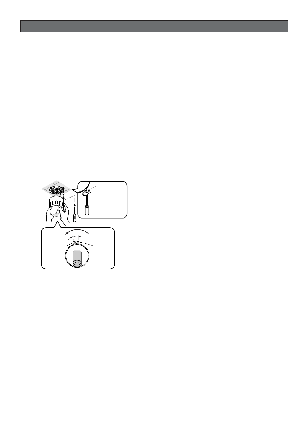
8. Fix the decoration cover to the camera mounting
base.
a. Sideway Cable Exit
Pass the cables through the cutout made in the
diecast case and decoration cover.
b. Top Cable Exit
Push the decoration cover against the camera
mounting base.
Be sure to match the wire with the fall
prevention wire fixing angle as shown below.
Fall prevention
wire fixing angle
Ring of the
fall prevention
wire
15°
-16-
UNINSTALLING THE CAMERA
Caution:
Make sure you perform the steps below carefully
and exactly when uninstalling the camera and deco-
rative cover. Failure to do so creates the risk of dam-
age to the camera.
■Uninstalling the Camera
The camera and its base unit are secured by screws.
This configuration provides double anchoring, and you
should use the following procedure to uninstall the cam-
era.
1. Remove the fixing screw that secures the camera to
the mounting base.
Put the screw in a place where it will not become
lost.
2. Remove the camera from the mounting base.
Rotate the camera in the direction indicated by the
arrow and remove it.
3. Remove the safety wire from the mounting base.
Camera Camera
Mounting
Base
Fixing screw
Rotate
15°
After loosening
the screw, press
upwards on the
camera and then
remove it.
-17-
CONNECTIONS
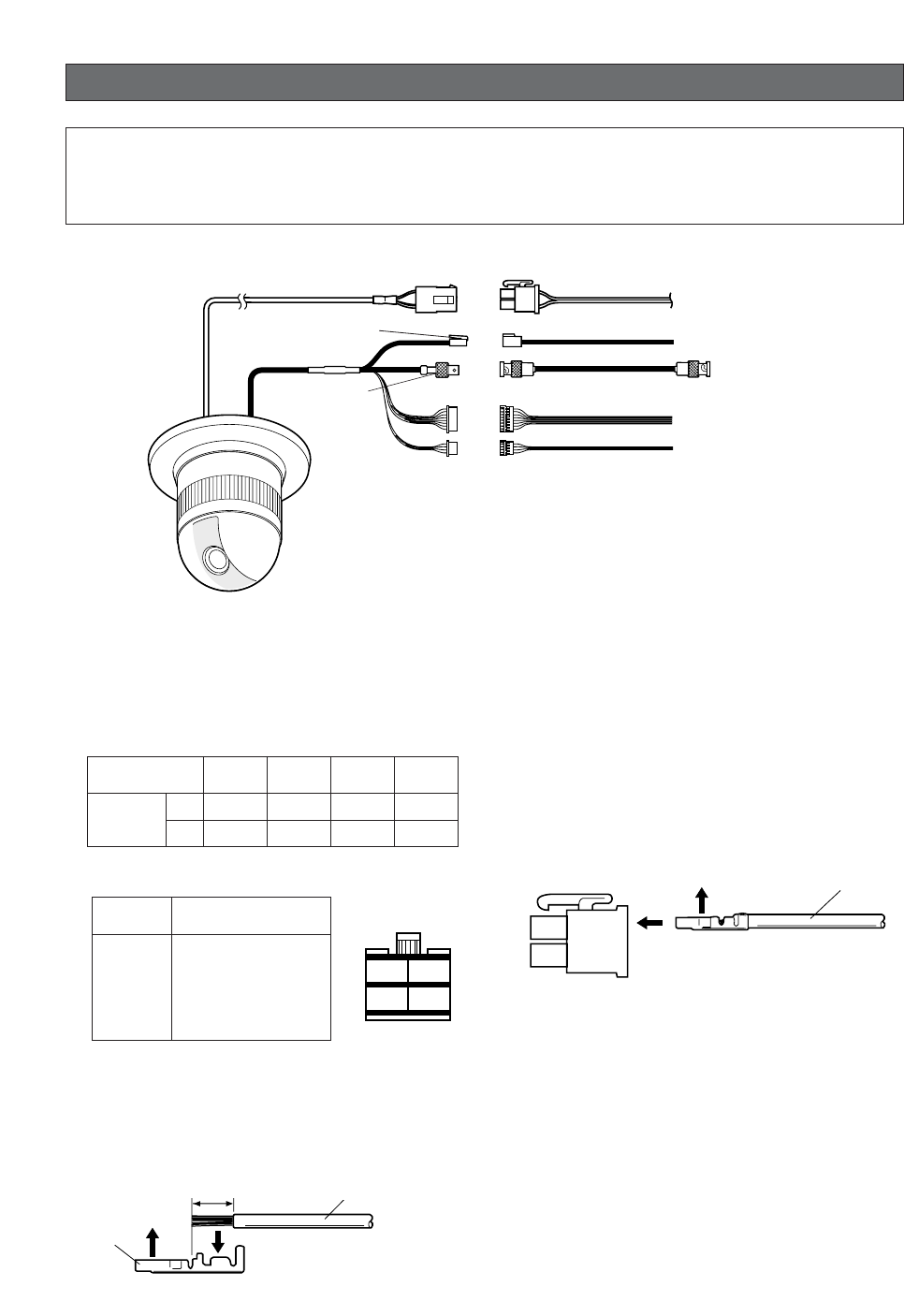
How to Assemble the Cable with the Accessory
Connector
Strip back the cable jacket approx. 3 mm (0.1 inch) and
separate the individual conductors.
Prepare the individual conductors for clamping. Use
MOLEX band tool part number 57027-5000 (for UL-
Style Cable UL1015) or 57026-5000 (for UL-Style
UL1007) for clamping the contacts.
After clamping the contacts, push them into the proper
holes in the accessory connector of this camera until
they snap in place.
CAUTIONS
•Shrinking the cable-entry seal is a one-time proce-
dure. Do not shrink the cable-entry seal until ascer-
taining that the unit is functioning.
•CONNECT THIS TO 24 V AC CLASS 2 POWER SUP-
PLY ONLY.
Precautions
•The following connections should be made by qualified service personnel or system installers in accordance
with all local codes.
•See the reverse side of the cover page for main lead connection.
✻The coaxial cable length (RG-59/U, BELDEN 9259) for the connection
is up to 1 200 meters (4 000 ft.)
To VIDEO IN
(CAMERA IN)
Video output
24 V AC
BNC plug
Coaxial cable
RS485 cable
Data port
BNC plug
Alarm in
Alarm out
To sensors
To indicators
24 V AC cable
Note:
When powered up, the unit performs a self-check (including one panning, tilting, zooming and focusing opera-
tion).
Recommended wire gauge sizes for 24 V AC line
#24
(0.22mm2)
Copper wire size
(AWG)
Length
of cable
(approx.)
(m)
(ft)
#22
(0.33mm2)#20
(0.52mm2)#18
(0.83mm2)
20 30 45 75
65 100 160 260
Pin no. Power source
1
2
3
4
24 V AC LIVE
24 V AC NEUTRAL
Ground
Not use
1
3
2
4
• 24 V AC Power Supply Connection
Accessory Connector Information
Contact Insert
Up A
Approx.
3 mm (0.1 inch)
Insert the wire until A position
and clamp the contacts.
Wire
Up
Contact
Wire
Approx.
3 mm (0.1 inch)
Insert the wire until A position
and clamp the contacts.
Contact
Up Wire
Up Wire
Contact
-18-
Note:
Use the cable that is described below for RS485 site
communication.
•Shielded, twisted pair cable
•Low impedance
•Wire gauge size is thicker than AWG #22
(0.33 mm2).
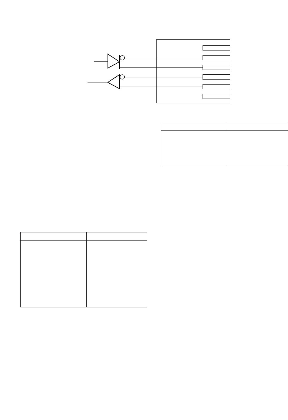
• ALARM IN Connections
An 8-pin and a 4-pin harness are supplied with the
camera as standard accessories. Connect external
sensors to this connector. Input specifications are low-
active, non-voltage contact (ON when active) or open
collector (Low when active). The table below shows
wire colors versus pin functions.
Note:
Use a relay if the voltage or current of the connected
device exceeds the ratings.
Red
Data transmission
Data reception
Orange
Yellow
Green
T (B)
T (A)
R (B)
R (A)
• RS485 Connection
Black
Brown
Red
Orange
Yellow
Light blue or green
Blue
Purple
Wire color Function
IN 1
GND
IN 2
GND
IN 3
GND
IN 4
GND
Alarm IN (8-pin)
• ALARM OUT Connections
Connect an external device, for example, a buzzer or
lamp, to this connector. Output specifications are low-
active, open-collector and a drive capacity of 16 V DC
100 mA maximum. The table below shows wire colors
versus pin functions.
Gray
White
Pink
Yellow green or light blue
Wire color Function
OUT 1
GND
OUT 2
GND
Alarm OUT (4-pin)
-19-
RS485 SETUP
Use the following procedure to configure the RS485
setup when you want to use the system controller to
control the camera (pan, tilt, etc.) via the camera's data
port.
1. Display the setup menu (page 26), move the cursor
to RS485 SETUP O, and then press the CAM (SET)
button.
This will display the RS485 setup menu.
2. Check the unit number. (page 12)
The UNIT NUMBER item shows the unit number
specified by DIP Switch 1. The factory default unit
number is 1.
If DIP Switch 1 specifies 1 to 96 as the unit number,
move the cursor to UNIT NUMBER and then tilt the
joystick left or right to select a unit number (1 to 96).
Note:
It is not necessary to configure the RS485 SETUP
menu SUB ADDRESS setting.
3. Move the cursor to BAUD RATE, and then tilt the joy-
stick left or right to select a baud rate setting.
Tilting the joystick cycles through the baud rate
(transmission speed) display in the sequence shown
below. (unit: bits/s) The factory default setting is
19200.
4. Move the cursor to DATA BIT, and then tilt the joy-
stick left or right to select a data bit setting (7 or 8).
The factory default setting is 8.
5. Move the cursor to PARITY CHECK, and then tilt the
joystick left or right to select a parity bit setting
(NONE, ODD, EVEN).
The factory default setting is NONE.
6. Move the cursor to STOP BIT, and then tilt the joy-
stick left or right to select a stop bit setting (1 or 2).
The factory default setting is 1.
7. Move the cursor to XON/XOFF, and then tilt the joy-
stick left or right to select an XON/XOFF setting.
The factory default setting is NOT USE.
NOT USE: Disables X ON/X OFF data flow control.
USE: Enables X ON/X OFF data flow control.
8. Move the cursor to WAIT TIME, and then tilt the joy-
stick left or right to select a wait time setting.
The wait time is the time that the camera should wait
before resending data when no receive acknowl-
edgement (ACK) is returned after data is sent.
Tilting the joystick cycles through the wait time dis-
play in the sequence shown below. (unit: ms) The
factory default setting is OFF.
9. Move the cursor to ALARM DATA, and then tilt the
joystick left or right to select an alarm data send
mode setting.
POLLING: Sends alarm data in response to a
request by the system controller.
AUTO1: Sends alarm data each time an alarm sig-
nal is input.
AUTO2: Sends alarm data at five-second intervals.
This is the factory default setting.
Note:
When using the preset alarm (page 41), select
"AUTO1".
10.Move the cursor to DELAY TIME, and then tilt the
joystick left or right to select a delay time setting.
The delay time is the time is the time the camera
should wait before sending a receive acknowledge
(ACK). The delay time display changes in the
sequence shown below. (unit: ms) The factory
default setting is OFF.
This setting can be configured only when 2-line con-
figuration is selected by DIP Switch 2. (page 11)
* RS485 SETUP *
UNIT NUMBER
SUB ADDRESS
BAUD RATE
DATA BIT
PARITY CHECK
STOP BIT
XON/XOFF
WAIT TIME
ALARM DATA
DELAY TIME
RET
1
-----
19200
8
NONE
1
NOT USE
OFF
AUTO2
OFF
2400 4800 9600 19200
OFF ↔ 100MS ↔ 200MS ↔ 400MS ↔ 1000MS
OFF ↔ 100MS

USING THE SETUP MENU
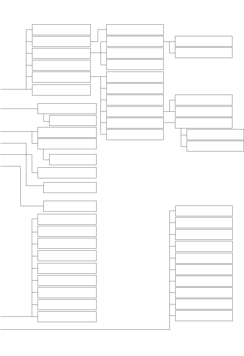
■Setup Menu
Setup menus are shown in the diagram below. You can adapt the camera to your requirements by setting up the
respective items in these menus. Menus are incorporated in a hierarchical structure, from the setup menu at the top
to manual mask area selection at the bottom. These menus are described on the following pages for reference.
Switches, buttons, keys and the joystick are used in the setup operations.
-20-
Setup
Menu
Preset Menu (P. 26)
Map Menu
Home Position Setting (P. 31)
Self Return Setting (P. 31)
Auto Mode Selection (P. 32)
Auto Pan Key Setting (P. 33)
Special 1 Menu (P. 35)
Digital Flip Setting (P. 34)
Camera Menu (P. 42)
Camera ID Editing (P. 42)
Shutter Speed Setting (P. 44)
AGC Mode Selection (P. 45)
Electronic Sensitivity
Enhancement (P. 45)
Synchronization (P. 45)
White Balance (P. 46)
Motion Detector (P. 47)
Auto Focus Setting (P. 48)
Special 2 Menu (P. 49)
RS-485 Setup (P. 19)
Password Lock (P. 34)
Preset No.Setting (P. 26)Preset Setting Menu
(P. 26)
Auto Pan Setting (P. 32)
INT Manual Selection (P. 45)
LL Manual Selection (P. 45)
VD2 Automatic Selection
(P. 45)
Manual Level Adjustment
(ATW1, ATW2) (P. 46)
Manual Level Adjustment
(AWC) (P. 47)
Sensitivity Level Adjustment
(P. 47)
Manual Mask Area
Selection (P. 45)
Camera ID Display Position
(P. 42)
ALC Mode with BLC ON
(P. 43)
V-phase Manual
Adjustment (P. 45)
Privacy Zone ON/OFF
(P. 35)
Proportional Pan/Tilt
(P. 36)
Area Title (P. 37)
Patrol Learn (P. 38)
Alarm IN/OUT (P. 40)
Cleaning (P. 41)
Electric Zoom (P. 41)
Preset Alarm (P. 41)
Image Hold (P. 42)
Tilt Angle (P. 42)
Mask Area Selection
(P. 47)
Demonstration Display
Password Registration
(P. 34)
Password Verification (P. 34)
ALC Mode with BLC OFF
(P. 44)
Light Control Setting (P. 43)
-21-
Position Setting (P. 27)
Dwell Time Setting (P. 30)
Chroma Level Setting (P. 49)
Aperture Level Setting (P. 49)
Pedestal Level Setting (P. 49)
Resolution (P. 49)
HUE Level Setting (P. 49)
Digital Noise Reduction
(P. 49)
PIX OFF Setting (P. 49)
BLC OFF (P. 44)
Preset ID Editing (P. 27)
BLC ON (P. 43)
Manual Iris Adjustment (P. 43)
Shutter Speed (P. 44)
Gain Control (P. 45)
Electronic Sensitivity
Enhancement (P. 45)
White Balance (P. 46)
Motion Detector (P. 47)
Auto Focus (P. 48)
Unit Number (P. 19)
Sub Address (P. 19)
Baud Rate (P. 19)
Data Bit (P. 19)
Parity Check (P. 19)
Stop Bit (P. 19)
X On/X Off (P. 19)
Wait Time (P. 19)
Alarm Data (P. 19)
Delay Time (P. 19)
Light Control Setting (P. 29)
To Restore the Camera Default
Position (P. 50)
Camera Resetting (P. 50)
Zone Number Selection (P. 35)
Zone Parameter Setting
(P. 35)
Setting for ON (USER) (P. 37)
Setting for ON (NESW) (P. 37)
Area Title Display (P. 38)
Learning Display (P. 39)
Alarm IN/OUT Setting (P. 40)
Cleaning Display (P. 41)
Scene File Setting (P. 30)
Preset Speed (P. 30)
Manual Level Adjustment
(Contrast) (P. 44)
Manual Mask Area Selection
(P. 44)
Manual Level Adjustment
(ATW1, ATW2) (P. 46)
Sensitivity Level Adjustment
(P. 47)
Mask Area Selection (P. 48)
Demonstration Display
Manual Level Adjustment
(AWC) (P. 46)
Preset Identification Setting
(P. 28)

-22-
■Setup Menu Description
●Presetting
(1) Position (POSITION SET)
Aligns the camera position and focal point by pan-
ning, tilting, zooming and focusing.
See page 27 for the setting.
(2) Preset Identification (PRESET ID)
Assigns the name for preset IDs (identification of up
to 16 alphanumeric characters) and can be
switched on or off on the monitor screen.
See page 28 for the setting.
(3) Light Control (ALC/MANUAL)
Selects the ALC or MANUAL mode for adjusting the
lens iris.
See page 29 for the setting.
(4) Dwell Time (DWELL TIME)
Displays the picture at each camera position for the
selected duration.
You can select a preset duration from the menu.
See page 30 for the setting.
(5) Scene File (SCENE FILE)
Stores up to 10 files.
Each file has a set of detailed parameters for the
shutter speed, AGC, electronic sensitivity enhance-
ment, white balance, motion detector and AF mode.
The scene files can be recalled later to reproduce
the parameter settings under the same conditions
as stored in the files.
See page 30 for the setting.
●Home Position (HOME POSITION)
The home position is the camera’s basic position.
The camera returns to this position automatically after a
specific time following a manual operation. This setting
functions only when AUTO MODE is OFF.
See page 31 for the setting.
●Self Return (SELF RETURN)
The self return function allows the camera to resume
one of the operations described below after specified
time.
This function automatically works after a lapse of setting
time from manual operation finished.
OFF: Cancels the auto mode (SEQ, SORT, AUTO PAN
and PATROL).
AT (the auto mode is set to OFF): Shifts the camera
direction to the home position.
AT (the auto mode is set to other than OFF):
Activates the auto mode.
HP: Shifts the camera direction to the home position.
AP: Starts the auto pan function.
SQ: Starts the sequence function.
SR: Starts the sort function.
PT: Starts the patrol function.
See page 31 for the setting.
●Auto Mode (AUTO MODE)
The auto mode is used for setting the movement of the
camera.
You can select one of four automatic operation modes
and one manual operation mode as follows:
OFF: No automatic operation. The camera can be oper-
ated only manually.
SEQ: The camera operates in the sequence of preset
positions in numerical order.
SORT: The camera operates in the sequence of preset
positions counterclockwise from pan starting point.
AUTO PAN: The camera automatically turns within the
preset panning range.
PATROL: The camera operates in the patrol-learn func-
tion.
See page 32 for the setting.
●Auto Pan Key (AUTO PAN KEY)
This setting assigns the SEQ, SORT, AUTO PAN or
PATROL (PLAY) mode to the AUTO button on the con-
troller.
After this setting, the AUTO button performs as
assigned.
Note:
The AUTO PAN LED on the controller does not light
if a mode other than AUTO PAN is assigned.
●Digital Flip (DIGITAL FLIP)
Tilt range is limited within –5° to 90° if OFF is selected.
If ON is selected it widens the range up to 190° with
the digital flip that reverses horizontal and vertical scan-
ning when the camera is tilted beyond 90° point
(Downright position if the camera is installed on a ceil-
ing). Tilt range narrows from –5° to 90° if PAN LIMIT is
set to ON.
Note:
When trying to set preset positions directly from the
WV-CU360 System Controller for the first time while
the camera is tilted beyond 90˚, the INHIBIT indica-
tion will be displayed on the monitor screen. This
indication will disappear when trying the next time
and it will be possible to register the preset position.
●Password Lock (PASSWORD LOCK)
This menu limits setting changes.

-23-
●Special 1 Menu
(1) Privacy Zone (PRIVACY ZONE)
This setting is used for masking unwanted zones,
hiding them from display on the monitor screen.
Up to 8 zones can be registered. Submenus are
provided for zone number selection and parameter
setting. See page 35 for details.
(2) Proportional Pan-Tilt Speed (PROPO. P/T)
If ON is selected, the pan-tilt speed changes auto-
matically corresponding to the zoom ratio. For
example, the pan-tilt speed slows down when the
camera zooms in. See page 36 for details.
(3) Area Title (AREA TITLE)
Up to 8 area titles can be assigned to specific
scenes on the DIRECTION (NESW) menu or by
alphanumeric (USER) assignment. The area title is
displayed under the camera ID on the monitor
screen when the camera turns to a position that has
been assigned an area title. See page 37 for details.
(4) Patrol-learn and Patrol Play (PATROL)
A set of manual operations is stored (LEARN), repro-
duced (PLAY) or turned inactive (OFF). Patrol opera-
tion stops if SEQ, SORT or AUTO PAN is set to
AUTO MODE on the SETUP menu. See page 38 for
details.
(5) Alarm Input/Output (ALARM IN/OUT)
Alarm input and output are set on a submenu.
Preset positions are assigned to ALARM IN 1 to 4.
When alarm inputs are supplied via the alarm input
connector, the camera turns to the respective posi-
tions. Then the camera sends output signals via the
alarm output connector or the coaxial cable to the
external devices. CNT-CLS (Contact Closure) 1, 2
and COAX ALM OUT are used for alarm output set-
ting. See page 40 for details.
(6) Cleaning (CLEANING)
This is used for refreshing the electro-mechanical
contacts built in the camera. Use this function for
maintenance when the camera has been directed at
a specific spot or panned over a specific range for a
long time.
(7) Electronic Zoom (EL-ZOOM)
Up to 10-fold electronic zooming is available
besides 22-fold optical zooming.
(8) Preset Alarm (PRESET ALM)
Alarm signals are generated in the following cases if
ON is selected.
•When a preset positioning sequence is completed
while AUTO MODE is set to SEQ.
•When a preset positioning sequence is completed
while AUTO MODE is set to SORT.
•Positioning is completed at the HOME position in the
SELF RETURN mode.
•Positioning is completed in the ALARM IN mode.
•When positioning to the starting point is completed
while AUTO MODE is set to AUTO PAN.
•When positioning to the starting point is completed
while PATROL is set to PLAY.
(9) Image Hold (IMAGE HOLD)
The camera picture remains as a still image on the
monitor screen or until the camera reaches the pre-
set position. This function is useful for surveillance
via a local area network.
(10)
Tilt Angle 0 °/5 °
You can select a titling range. If 5° is selected, the
tilting angle is adjustable up to 5° beyond the hori-
zontal position.
●Camera
(1) Camera Identification (CAMERA ID)
You can use the camera identification to assign a
name to the camera. The camera ID consists of up
to 16 alphanumeric characters. You can select
whether to have the camera ID displayed on the
monitor screen or not. See page 42 for the setting.
(2) Light Control (ALC/MANUAL)
You can select a mode for adjusting the lens iris.
There are two modes as follows:
ALC: The lens iris is automatically adjusted accord-
ing to the brightness of an object.
You can select one of two modes (BLC ON or
BLC OFF) of backlight compensation.
Backlight compensation is available in the ALC
mode. It eliminates strong background light
which makes the camera picture dark such as a
spotlight.
MANUAL: The lens iris is fixed at the value that you
have set regardless of the brightness of an
object.
•ALC Mode with BLC ON
The important object in a scene is usually placed in
the center of the monitor’s screen. In the BLC mode,
photometric weight is given more to the center of the
screen (where the important object is located) than
to the edge of the picture (where a bright backlight
would most likely to be located).
You can use the BLC function if you select ALC. The
function eliminates interference by strong back-
ground lighting which makes the camera picture
dark, such as a spotlight.
See page 43 for the setting.

-24-
•ALC Mode with BLC OFF
In this mode, the picture is divided into 48 areas. If
there is a source of brightness that interferes with
the clarity of the picture in these masks, correspon-
ding areas mask the light to keep the clarity of the
picture.
Generally, when a light from the background is too
strong such as a spotlight, all objects except the
main object in the picture are displayed darker
because the lens iris is adjusted with respect to
strong brightness. This model ignores strong bright-
ness by masking the source of the strong bright-
ness, thereby the main object is displayed clearly.
Note:
The result of field setup of the mask area and level
adjustment is fed back (effected) to the lens iris con-
trol in the ALC mode.
(3) Shutter Speed (SHUTTER)
You can select a shutter speed from among 1/60
(OFF), AUTO, 1/100, 1/250, 1/500, 1/1 000,
1/2 000, 1/4 000, and 1/10 000 seconds.
See page 44 for the setting.
(4) Gain Control (AGC)
You can set the gain of an image to automatic
adjustment [AGC ON (LOW, MID, HIGH)] or fixed
(AGC OFF).
See page 45 for the setting.
(5) Electronic Sensitivity Enhancement (SENS UP)
The electronic sensitivity enhancement function
varies the shutter speed to increase the sensitivity in
low light conditions.
You can select either of the following shutter speeds
for SENS UP.
1/30 seconds (x2), 1/15 seconds (x4), 1/10 seconds
(x6), 1/6 seconds (x10), 1/3.8 seconds (x16) or 1/1.9
seconds (x32).
See page 45 for the setting.
There are two modes for SENS UP as follows:
AUTO: If you select x32, the sensitivity is increased
automatically up to x32.
FIX: If you select x32, the sensitivity is increased to
a fixed x32.
Notes:
•Moving objects will appear blurred when shot in the
electronic sensitivity enhancement mode since
SENS UP is equivalent to reducing the shutter
speed in a still picture camera.
•The horizontal and vertical resolution will be lowered
in this mode.
•If the iris opening is too small, the SENS UP/AUTO
mode will not function.
(6) Synchronization (SYNC)
You can select the internal sync (INT) mode or the
line-lock sync (LL) mode. Additionally, this model
accepts the VD2 signal from a specified component.
Whenever the VD2 signal is supplied to this camera,
the camera automatically switches to the VD2 sync
mode.
When you select the line-lock (LL) mode, you can
adjust vertical phase.
See page 45 for the setting.
Important Notices:
The priorities of sync modes are assigned as fol-
lows:
1. Multiplexed vertical drive (VD2) (highest)
2. Line-lock (LL)
3. Internal sync (INT) (lowest)
Note:
The priorities of the automatic sync modes are the
same as the above.
(7) White Balance (WHITE BAL)
You can select either of three modes shown below
for white balance adjustment:
•Auto-Tracing White Balance (ATW1)
In this mode, the color temperature is monitored
continuously and thereby white balance is set auto-
matically. The color temperature range for the prop-
er white balance is between approx. 2 700 and
6000 K. Proper white balance may not be obtained
under the following conditions:
1. When the color temperature is out of the range of
2 700 - 6 000 K.
2. When the scene contains mostly high color tem-
perature (bluish) objects, such as a blue sky.
3. When the scene is dim.
In these cases, select the AWC mode.
•Auto-Tracing White Balance (ATW2)
This mode enables the camera to trace the white
balance when it is used in an area lit by sodium
lamps.
•Automatic White Balance Control (AWC)
In this mode, accurate white balance is obtained
within a color temperature range of approx. 2 300 -
10 000 K.
See page 47 for the setting.
(8) Motion Detector (MOTION DET)
The motion detector detects motion in a scene by
monitoring changes in the brightness level. You can
select the sensitivity level for the motion on the setup
menu.
When the camera detects motion, it sends an alarm
signal to the external equipment and stops at its
position for the preset dwell time.
See page 47 for the setting.

-25-
(9) Auto Focus (AF MODE)
The camera adjusts the focus automatically by sens-
ing the center of the picture. S, M and L stand for
the size of the sensing area: Small, Middle and
Large.
See page 48 for details.
MANUAL S, M, L: Auto-focus is activated only when
the button that is assigned for the auto-focus
function on the controller is pressed.
AUTO S, M, L: Auto-focus is activated automatically
while a manual pan, tilt or zoom operation is per-
formed.
Note:
If SENS UP is set to ON except x2 FIX or x2
AUTO, the AUTO (S/M/L) mode is disabled and
the MANUAL (S/M/L) mode is automatically
selected.
(10)
Special 2 Menu (SPECIAL2)
This menu allows you to adjust and set up the fol-
lowing items and functions: chroma level, aperture
level and pedestal level.
You can also reset your parameters to the factory
default settings.
See page 49 for the setting.
(11)
Self-diagnosis Function
If the camera continues operating abnormally for 30
seconds or more due to such accident as external
noise, the camera will automatically reset its power.
In the case it happens frequently, check if there
would be any environmental cause.
●RS485 Communication
Refer to the following pages for the communication
parameter settings.
•Full/Half duplex (page 19)
•Transmission speed (4 900 - 19 200 bps) (page 19)
•Parity bit, Stop bit, Flow control (page 19)
•Wait time, Delay time, Alarm output (page 19)
•Camera units (96 units max.) (page 19)
•Termination ON/OFF (page 11)
•Reset parameters (page 13)
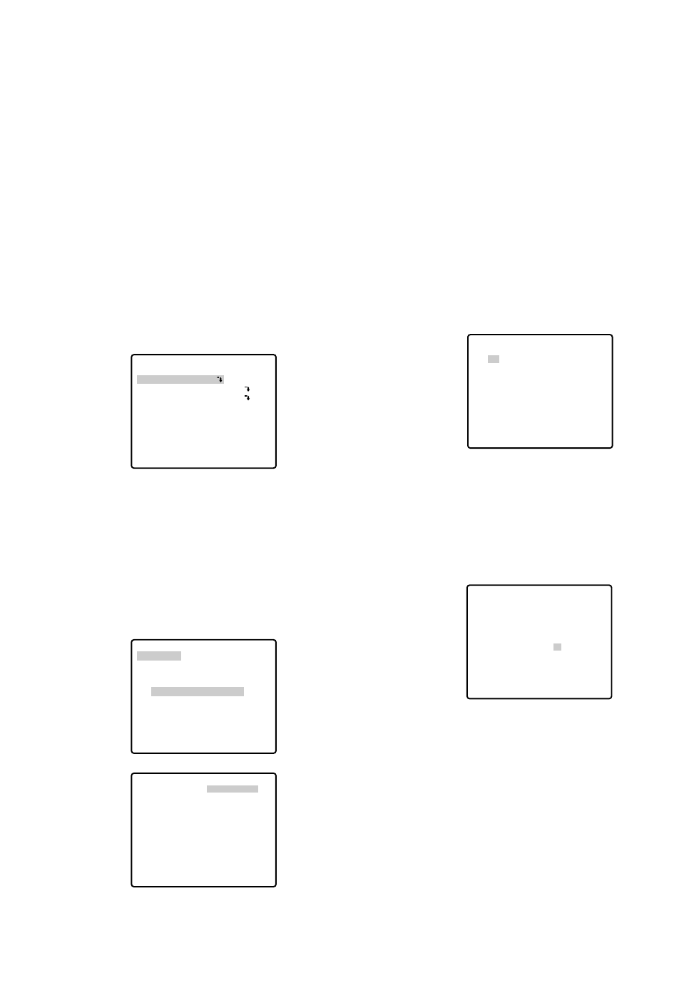
■Preset Menu
●Preset Menu Display
1. Displaying the preset menu directly
(1) Move the cursor to PRESET 1 Oand select the
position number with the joystick.
(2) Press the CAM (SET) button.
The preset setting menu appears on the monitor
screen.
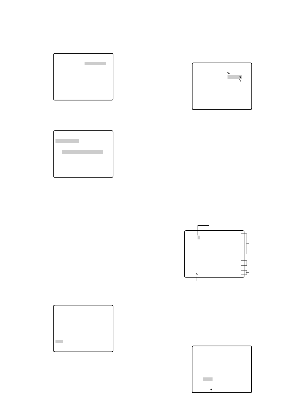
2. Displaying the preset menu from the PRESET NUM-
BER SET menu
(1) Move the cursor to MAP Oand press the CAM
(SET) button.
The PRESET NUMBER SET menu appears on the
monitor screen.
(2) Move the cursor to the position number to be set
and press the CAM (SET) button.
The preset setting menu appears on the monitor
screen.
** SET UP MENU **
PRESET 1
MAP
HOME POSITION
SELF RETURN
AUTO MODE
AUTO PAN KEY
DIGITAL FLIP
SPECIAL1
CAMERA
RS485 SET UP
PASSWORD LOCK OFF
OFF
OFF
OFF
AUTO PAN
ON
** SET UP MENU **
PRESET 1
MAP
HOME POSITION
SELF RETURN
AUTO MODE
AUTO PAN KEY
DIGITAL FLIP
SPECIAL1
CAMERA
RS485 SET UP
PASSWORD LOCK OFF
OFF
OFF
OFF
AUTO PAN
ON
** PRESET NUMBER SET **
2
6
10
14
18
22
26
30
1*
5
9
13
17
21
25
29
ID:DOOR
RET
3
7
11
15
19
23
27
31
4
8
12
16
20
24
28
32
SETTING PROCEDURES
The following setting procedures are described on the
assumption that this model is used in combination with
WJ-SX150 Matrix Switcher and WV-CU650 System
Controller.
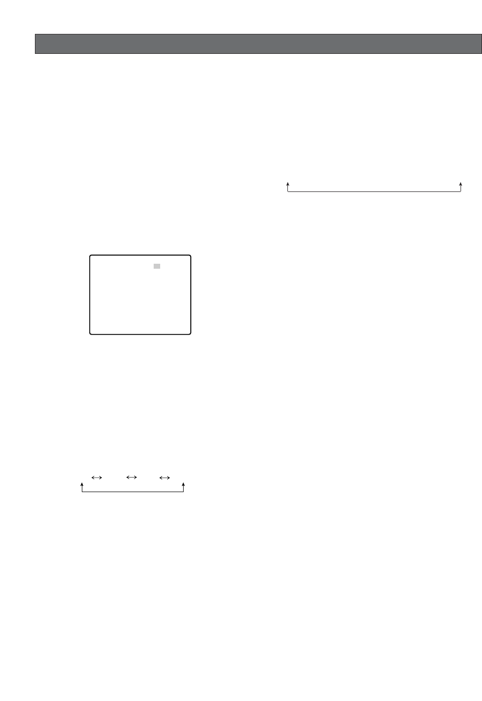
■Menu Display
●Setup Menu Display
WV-CU650
1. Select the camera you want to set up (this camera),
and the monitor where you want to display the setup
menu.
2. Press the MENU button to display LCD MENU CAM
101.
3. Press the ENTER button or CAM (SET) button to dis-
play Camera Setup.
4. Press the F1 button.
WV-CU161C
Press the CAMERA SETUP button for 2 seconds or
more to open the SETUP menu.
●Submenu Display
The items marked Ocan be selected/changed on the
submenu.
•Move the cursor to an item with the Omark and
press the CAM (SET) button. The submenu appears.
-26-
** SET UP MENU **
PRESET 1
MAP
HOME POSITION
SELF RETURN
AUTO MODE
AUTO PAN KEY
DIGITAL FLIP
SPECIAL1
CAMERA
RS485 SET UP
PASSWORD LOCK OFF
OFF
OFF
OFF
AUTO PAN
ON
* RS485 SET UP *
UNIT NUMBER
SUB ADDRESS
BAUD RATE
DATA BIT
PARITY CHECK
STOP BIT
XON/XOFF
WAIT TIME
ALARM DATA
DELAY TIME
RET
1
1
19200
8
NONE
1
NOT USE
OFF
AUTO2
OFF
-27-
Notes:
•The * mark indicates that the position number
has been preset.
•The character H refers to the home position.
•The second line from the bottom shows the pre-
set ID corresponding to the selected number.
"DOOR" next to "ID" in the example shown right is
for preset position number 1.
•Preset numbers 1 to 4 are linked to alarm inputs
1 to 4 respectively. If alarm input 1 comes in, the
camera turns to preset position 1, and to other
positions according to alarm input 2, 3 or 4.
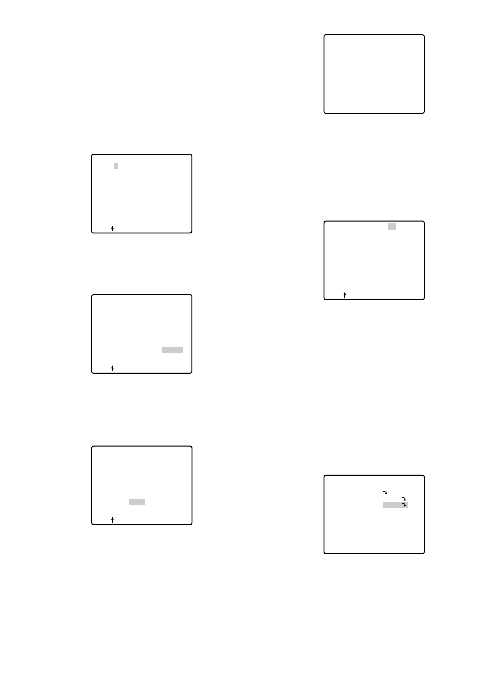
●Position Setting (POSITION SET)
1. Move the cursor to POSITION SET on the preset set-
ting menu and press the CAM (SET) button.
The position setting menu appears.
2. To Set Panning/Tilting Positions
(1) For PAN/TILT, move the cursor to PUSH SET and
press the CAM (SET) button. The PAN/TILT setting
menu appears.
(2) Select panning/tilting positions with the joystick, and
press the CAM (SET) button.
The positions are set and the screen returns to the
position setting menu.
PRESET NO. 1*
POSITION SET
PRESET ID
ALC/MANUAL
DWELL TIME
SCENE FILE
PRESET SPEED
RET DEL
ON
ALC
10S
1
••••••••|
L H
→
PUSH SET
→
PUSH SET
** POSITION 1 **
PAN/TILT
ZOOM/FOCUS
PAN OFFSET SET
← −
0.0
→
RET
FLOOR1
DOOR
→
PUSH SET
→
PUSH SET
** POSITION 1 **
PAN/TILT
ZOOM/FOCUS
U TILT D/L PAN R
PAN OFFSET SET
← −
0.0
→
RET
FLOOR1
DOOR
3. Pan Offset
If the camera is replaced with a new one, the pan
offset function is used to adjust its positions to be
the same as before except patrol setting.
The system controller can download or upload the
preset position data.
Caution:
The preset data for other cameras (WV-CS654
for example) is incompatible with WV-CS574.
WV-CS574's preset data will be destroyed if you
upload the conventional data. If this happened,
reset the WV-CS574 to the default settings.
Download the factory settings into the controller
and upload the correct preset data newly to the
initialized WV-CS574.
(1) Display the PRESET NUMBER SET menu.
(2) Select a position number for the picture to be most
enlarged among the numbers with the joystick. Then
press the CAM (SET) button. The position setting
menu appears.
(3) Move the cursor to PAN OFFSET SET and select the
right or left arrow with the joystick.
(4) Press the CAM (SET) button until the desired offset
value appears.
(5) Move the cursor to an item other than PAN OFFSET
SET, and press the MON (ESC) button.
Notes:
•Further adjustment of the other positions is
unnecessary. This adjustment applies to all other
positions.
•Make sure to move the cursor before pressing
the button in step 5. Otherwise the settings will
be ignored.
•Retry the loading when the camera fails to
upload or download the data.
** PRESET NUMBER SET **
2
6
10
14
18
22
26
30
1*
5
9
13
17
21
25
29
ID:DOOR
RET
3
7
11
15
19
23
27
31
4
8
12
16
20
24
28
32
→
PUSH SET
→
PUSH SET
** POSITION 1 **
PAN/TILT
ZOOM/FOCUS
PAN OFFSET SET
← −
0.0
→
RET
FLOOR1
DOOR
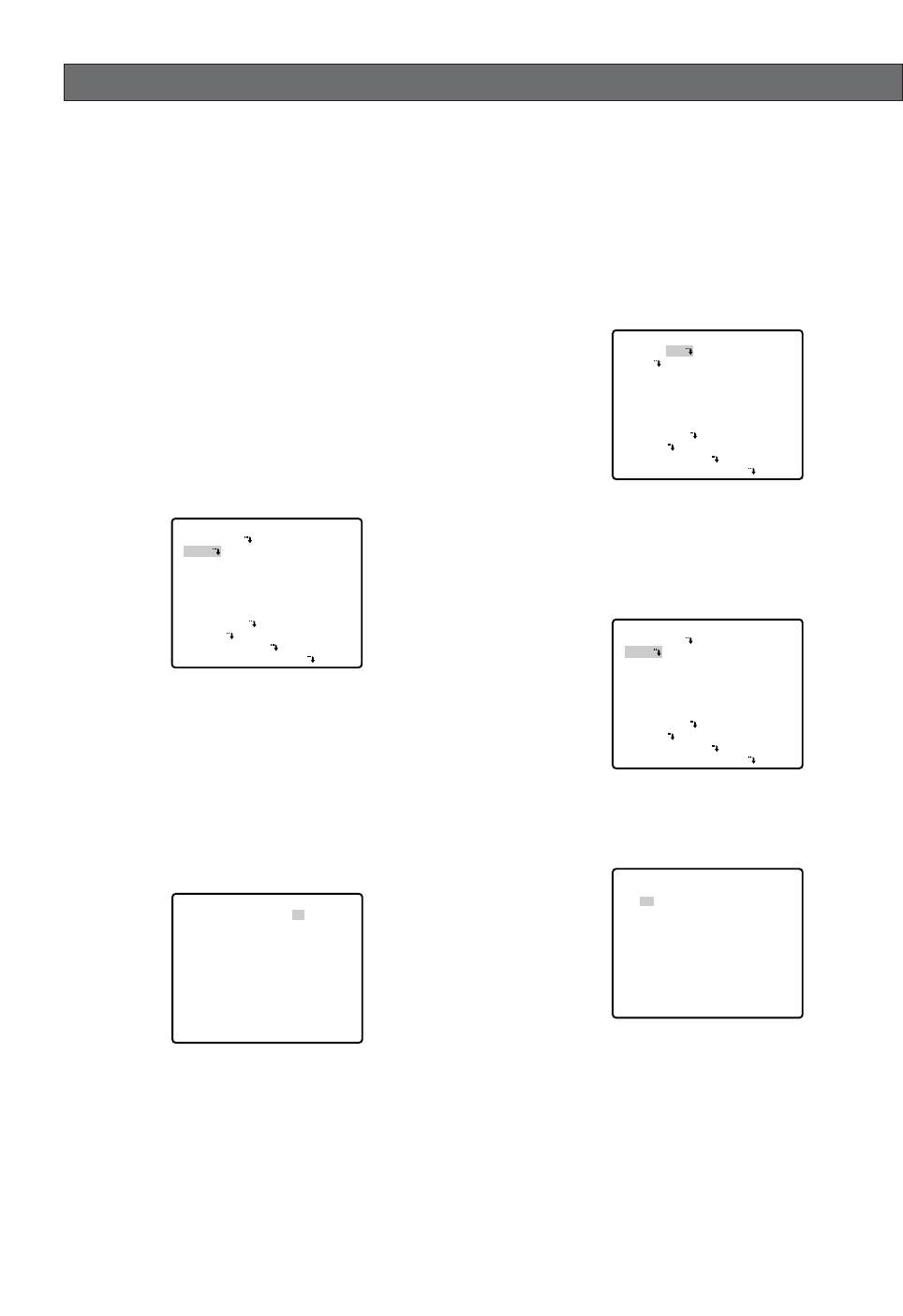
●Preset Identification Setting (PRESET
ID)
1. Move the cursor to PRESET ID on the preset setting
menu and select ON or OFF with the joystick.
The factory default setting is OFF.
ON: Preset ID appears on the monitor screen.
OFF: Preset ID does not appear.
2. Press the CAM (SET) button to display the preset ID
setting menu.
To Enter a New Preset ID
(1) Move the cursor to the desired character using
the joystick, and press the CAM (SET) button.
(2) The selected character appears in the editing
area. (The pointer in the editing area moves to
the right automatically at this moment.) To enter
a blank, select SPACE.
(3) Repeat the above procedure until all characters
are entered.
To Copy a Preset ID from Another Position
(1) Move the cursor to COPY and press the CAM
(SET) button. The preset ID in the preceding
position is immediately shown. Each consecutive
pressing of the CAM (SET) button displays the ID
preceding the one currently displayed.
PRESET NO. 1*
POSITION SET
PRESET ID
ALC/MANUAL
DWELL TIME
SCENE FILE
PRESET SPEED
RET DEL
ON
ALC
10S
1
••••••••|
L H
Command
Editing
Area
Character
Area
Pointer
Character Cursor
PRESET NO. 1*
0123456789
ABCDEFGHIJKLM
NOPQRSTUVWXYZ
().,'":;&#!?=
+-*/%$
SPACE
COPY POSI RET RESET
DOOR............
PRESET NO. 1*
0123456789
ABCDEFGHIJKLM
NOPQRSTUVWXYZ
().,'":;&#!?=
+-*/%$
SPACE
COPY POSI RET RESET
DOOR............
-28-
4. To Set the Lens Zoom and Focus Positions
(1) Move the cursor to PUSH SET for ZOOM/FOCUS
and press the CAM (SET) button. The ZOOM/
FOCUS setting menu appears.
(2) Select zoom/focus positions with the joystick, and
then press the CAM (SET) button.
The positions are set and the screen returns to the
position setting menu.
Notes:
•When the camera is used at a nearly horizontal
angle, the focus may not be adjustable to a high
level of accuracy because of the molding distor-
tion of the dome cover.
•If you move the cursor to the position number
and move the joystick right or left, the position
number can be selected.
The selected preset position number can also be
set after pressing the CAM (SET) button.
•The preset and camera IDs appear in the lower-
left corner of the position setting menu after set-
ting them.
5. Move the cursor to RET and press the CAM (SET)
button to return to the preset setting menu.
→
PUSH SET
→
PUSH SET
** POSITION 1 **
PAN/TILT
ZOOM/FOCUS
PAN OFFSET SET
← −
0.0
→
RET
FLOOR1
DOOR
** POSITION 1 **
PAN/TILT
ZOOM/FOCUS
U ZOOM D/L FOCUS R
PAN OFFSET SET
← −
0.0
→
RET
FLOOR1
DOOR
→
PUSH SET
→
PUSH SET
→
PUSH SET
→
PUSH SET
** POSITION 1 **
PAN/TILT
ZOOM/FOCUS
PAN OFFSET SET
← −
0.0
→
RET
FLOOR1
DOOR
-29-
(2) Display the most prospective ID.
(3) Follow the step "To Change an Entered Preset
ID" if necessary.
To Change an Entered Preset ID
(1) Move the pointer to the character to be edited in
the editing area with the joystick.
(2) Select a new character with the joystick.
(3) Press the CAM (SET) button to determine the
Preset ID.
To Delete an Entered Preset ID
Move the cursor to RESET and press the CAM (SET)
button.
To Set a Display Position for a Preset ID
(1) Move the cursor to POSI and press the CAM
(SET) button. The display position set menu
appears.
(2) Move the ID to the desired position with the joy-
stick, and press the MON (ESC) button. The dis-
play position is set and the monitor screen
returns to the preset ID setting menu.
PRESET NO. 1*
0123456789
ABCDEFGHIJKLM
NOPQRSTUVWXYZ
().,'":;&#!?=
+-*/%$
SPACE
COPY POSI RET RESET
DOOR............
PRESET NO. 1*
0123456789
ABCDEFGHIJKLM
NOPQRSTUVWXYZ
().,'":;&#!?=
+-*/%$
SPACE
COPY POSI RET RESET
DOOR............
PRESET NO. 1*
0123456789
ABCDEFGHIJKLM
NOPQRSTUVWXYZ
().,'":;&#!?=
+-*/%$
SPACE
COPY POSI RET RESET
DOOR............
To Enter the Next ID without Returning to the
Preset Setting Menu
(1) In the preset ID setting menu, move the cursor to
the top line and select a desired position number
with the joystick.
(2) Enter, copy, change or delete the ID as
described above.
To Return to the Preset Setting Menu
Move the cursor to RET and press the CAM (SET)
button.
●Light Control Setting (ALC/MANUAL)
1. Move the cursor to ALC/MANUAL and select ALC or
MANUAL with the joystick.
The factory default setting is ALC.
ALC: The lens iris is automatically adjusted to suit
the brightness of the object.
MANUAL: The lens iris is fixed at the set value
regardless of the brightness of the object.
2. In case of ALC O
Press the CAM (SET) button. The backlight compen-
sation menu appears on the monitor screen. See
page 43 for the setting.
3. In case of MANUAL O
Press the CAM (SET) button. The setting menu
appears on the monitor screen. Set the lens iris level
as desired with the joystick.
FLOOR 1
DOOR
PRESET NO. 1*
0123456789
ABCDEFGHIJKLM
NOPQRSTUVWXYZ
().,'":;&#!?=
+-*/%$
SPACE
COPY POSI RET RESET
DOOR............
PRESET NO. 1*
POSITION SET
PRESET ID
ALC/MANUAL
DWELL TIME
SCENE FILE
PRESET SPEED
RET DEL
ON
ALC
10S
1
••••••••|
L H
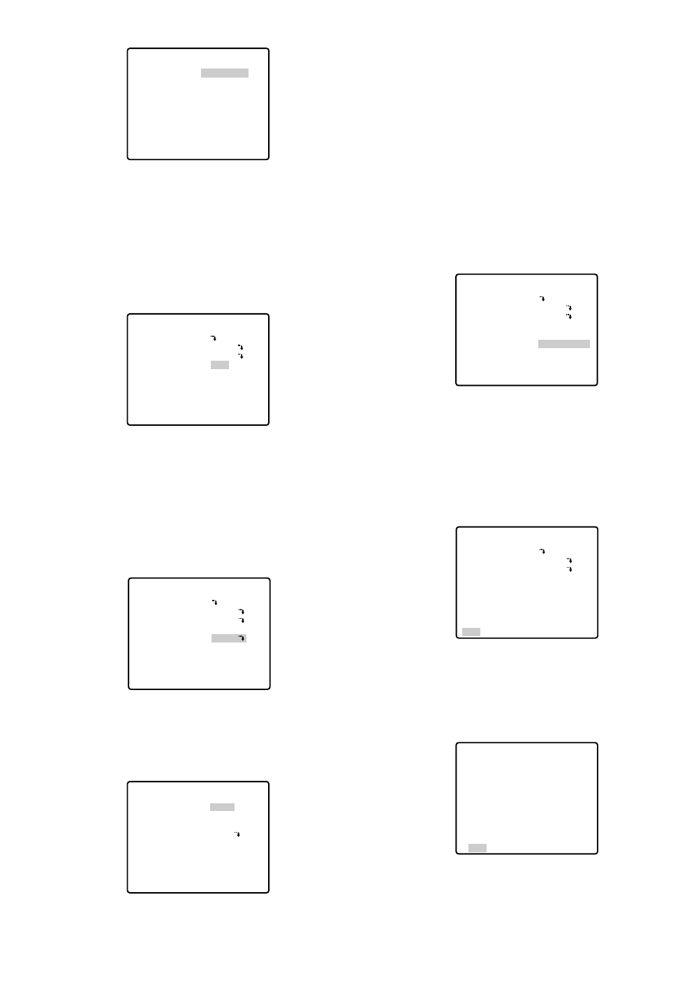
See the pages below for the settings respectively.
Shutter speed: page 44
AGC: page 45
Electronic sensitivity enhancement: page 45
White balance: page 46
Motion detector: page 47
Auto focus: page 48
●Preset Speed Setting (PRESET
SPEED)
Move the cursor to PRESET SPEED and select a speed
with the joystick.
●To Return to the Preset Number Set
Menu
Move the cursor to RET and press the CAM (SET) but-
ton. The PRESET NUMBER SET menu appears with the
* mark on the right of the preset position number.
●To Return to the Setup Menu
Move the cursor to RET and press the CAM (SET) but-
ton.
PRESET NO. 1*
POSITION SET
PRESET ID
ALC/MANUAL
DWELL TIME
SCENE FILE
PRESET SPEED
RET DEL
ON
ALC
10S
1
••••••••|
L H
PRESET NO. 1*
POSITION SET
PRESET ID
ALC/MANUAL
DWELL TIME
SCENE FILE
PRESET SPEED
RET DEL
ON
ALC
10S
1
••••••••|
L H
** PRESET NUMBER SET **
2
6
10
14
18
22
26
30
1*
5
9
13
17
21
25
29
ID:DOOR
RET
3
7
11
15
19
23
27
31
4
8
12
16
20
24
28
32
-30-
●Dwell Time (DWELL TIME)
•Move the cursor to DWELL TIME and set a dwell
time with the joystick. The factory default setting is
10S. Dwell time changes as follows:
S stands for second(s), and MIN stands for
minute(s).
●Scene File Setting (SCENE FILE)
1. To set a scene file number
Move the cursor to SCENE FILE and select a scene
file number (1 to 10, or OFF) with the joystick. The
factory default setting is 1. No scene file is selected
at OFF.
2. To set scene file details
Move the cursor to a scene file number and press
the CAM (SET) button. The setting menu appears.
** MANUAL CONT **
IRIS
RET
••••|••••
CLOSE OPEN
PRESET NO. 1*
POSITION SET
PRESET ID
ALC/MANUAL
DWELL TIME
SCENE FILE
PRESET SPEED
RET DEL
ON
ALC
10S
1
••••••••|
L H
PRESET NO. 1*
POSITION SET
PRESET ID
ALC/MANUAL
DWELL TIME
SCENE FILE
PRESET SPEED
RET DEL
ON
ALC
10S
1
••••••••|
L H
** SCENE FILE 1 **
SHUTTER
AGC
SENS UP
WHITE BAL
MOTION DET
AF MODE
RET
AUTO
ON(MID)
OFF
ATW1
1
MANUAL L
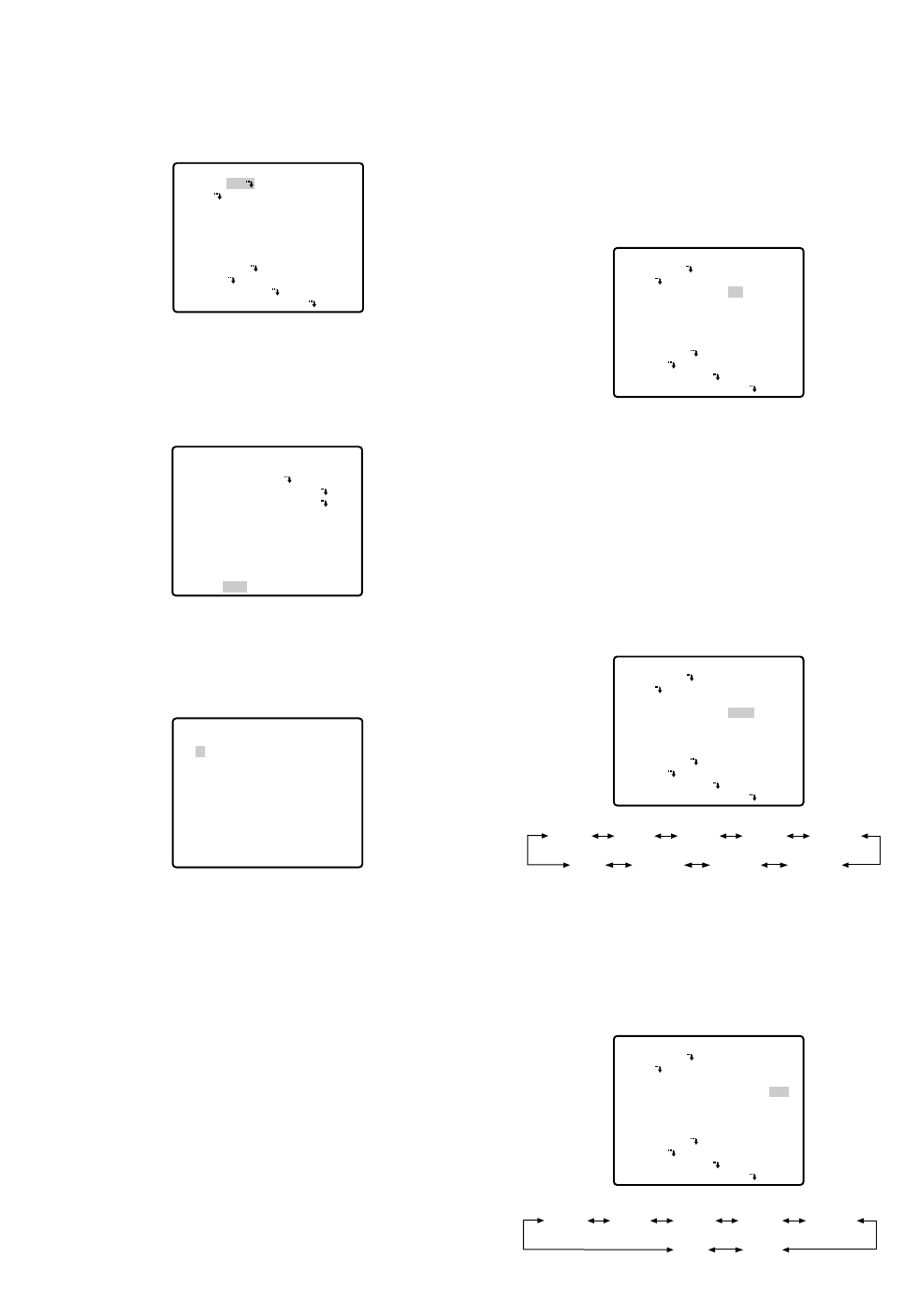
-31-
■Deleting Preset Positions
1. Move the cursor to PRESET 1 and select the position
number to be deleted with the joystick.
2. Press the CAM (SET) button to display the preset
setting menu.
3. Move the cursor to DEL and press the CAM (SET)
button.
This deletes the preset position and the PRESET
NUMBER SET menu appears. The * mark on the
right of the number disappears.
Note:
Your selected preset number is cancelled only in
the SEQ and SORT mode. The previously set
parameters (for PAN, TILT positions, etc.) are not
changed. If you want to change these parame-
ters, you must set them again.
** SET UP MENU **
PRESET 1
MAP
HOME POSITION
SELF RETURN
AUTO MODE
AUTO PAN KEY
DIGITAL FLIP
SPECIAL1
CAMERA
RS485 SET UP
PASSWORD LOCK OFF
OFF
OFF
OFF
AUTO PAN
ON
PRESET NO. 1*
POSITION SET
PRESET ID
ALC/MANUAL
DWELL TIME
SCENE FILE
PRESET SPEED
RET DEL
ON
ALC
10S
1
••••••••|
L H
** PRESET NUMBER SET **
2
6
10
14
18
22
26
30
1*
5
9
13
17
21
25
29
ID:DOOR
RET
3
7
11
15
19
23
27
31
4
8
12
16
20
24
28
32
■Home Position Setting (HOME
POSITION)
1. To set a position number for the home position
Move the cursor to HOME POSITION and select a
desired position number with the joystick.
2. Select OFF if you are not using the home position
function.
■Self Return Setting (SELF
RETURN)
You can set a return time and one of operation modes
with this menu.
1. Move the cursor to SELF RETURN, select a return
time from among the following with the joystick and
press the CAM (SET) button to confirm your selec-
tion.
MIN stands for minute(s).
2. Select an operation from among the following with
the joystick and press the CAM (SET) button to con-
firm your selection.
** SET UP MENU **
PRESET 1
MAP
HOME POSITION
SELF RETURN
AUTO MODE
AUTO PAN KEY
DIGITAL FLIP
SPECIAL1
CAMERA
RS485 SET UP
PASSWORD LOCK OFF
15
OFF
OFF
AUTO PAN
ON
** SET UP MENU **
PRESET 1
MAP
HOME POSITION
SELF RETURN
AUTO MODE
AUTO PAN KEY
DIGITAL FLIP
SPECIAL1
CAMERA
RS485 SET UP
PASSWORD LOCK OFF
1
OFF
OFF
AUTO PAN
ON
2MIN 3MIN 5MIN 10MIN
60MIN 30MIN 20MIN
1MIN
OFF
** SET UP MENU **
PRESET 1
MAP
HOME POSITION
SELF RETURN
AUTO MODE
AUTO PAN KEY
DIGITAL FLIP
SPECIAL1
CAMERA
RS485 SET UP
PASSWORD LOCK OFF
1
10MIN AT
OFF
AUTO PAN
ON
AT HP AP SQ
SR
OFF
PT
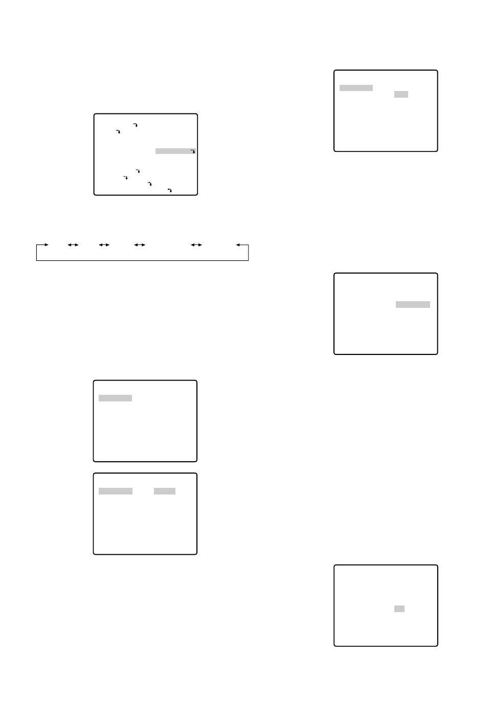
This determines the starting point and the cursor
moves to END.
(3) Move the joystick to select a panning endpoint
and press the CAM (SET) button.
This determines the endpoint and the cursor
moves to POSITION.
4. To set a panning speed
Move the cursor to SPEED, and set a panning
speed with the joystick.
The panning speed increases when the joystick is
moved to the right, and decreases when it is moved
to the left.
Caution:
If the panning range is changed after the camera
has not panned for a long time or has been panning
in the same panning range, the picture may not be
clear or noise may appear. In such cases, pan the
camera fully several times.
If this does not eliminate the problem, refer servicing
to qualified service personnel.
5. To set ENDLESS to ON/OFF
Move the cursor to ENDLESS, and select ON or OFF
with the joystick.
ON: The camera pans from the starting point to the
endpoint, and keeps rotating in the same direc-
tion to return to the starting point. Set PAN LIMIT
to OFF before ENDLESS is set to ON.
** AUTO PAN **
POSITION
SPEED
ENDLESS
DWELL TIME
PAN LIMIT
ZOOM LIMIT
RET
START
END
••••|••••
L H
OFF
1S
OFF
OFF
** AUTO PAN **
POSITION
SPEED
ENDLESS
DWELL TIME
PAN LIMIT
ZOOM LIMIT
RET
START
END
••••|••••
L H
OFF
1S
OFF
OFF
** AUTO PAN **
POSITION
SPEED
ENDLESS
DWELL TIME
PAN LIMIT
ZOOM LIMIT
RET
START
END
••••|••••
L H
ON
1S
OFF
OFF
-32-
■Auto Mode Selection (AUTO
MODE)
1. To set auto mode
Move the cursor to AUTO MODE and select a mode
with the joystick. Modes change as follows:
2. When AUTO PAN is selected, set details as follows:
Move the cursor to AUTO PAN Oand press the
CAM (SET) button to display the AUTO PAN setting
menu.
3. To set a panning starting point and panning end-
point
Follow the steps below.
(1) Move the cursor to POSITION and press the
CAM (SET) button. The cursor moves to START.
(2) Move the joystick to select a panning starting
point and press the CAM (SET) button.
** SET UP MENU **
PRESET 1
MAP
HOME POSITION
SELF RETURN
AUTO MODE
AUTO PAN KEY
DIGITAL FLIP
SPECIAL1
CAMERA
RS485 SET UP
PASSWORD LOCK OFF
OFF
OFF
AUTO PAN
AUTO PAN
ON
OFF SEQ SORT AUTO PAN PATROL
** AUTO PAN **
POSITION
SPEED
ENDLESS
DWELL TIME
PAN LIMIT
ZOOM LIMIT
RET
START
END
••••|••••
L H
OFF
1S
OFF
OFF
** AUTO PAN **
POSITION
SPEED
ENDLESS
DWELL TIME
PAN LIMIT
ZOOM LIMIT
RET
START
END
••••|••••
L H
OFF
1S
OFF
OFF
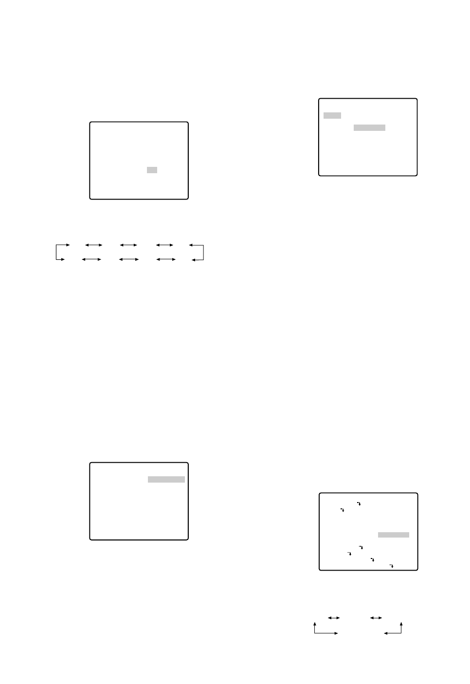
-33-
OFF: The camera pans from the starting point to the
endpoint, and rotates backward to the starting
point.
This movement is repeated over and over.
6. To set a dwell time
Move the cursor to DWELL TIME and select a dwell
time with the joystick.
Dwell time changes as follows: (unit: s)
7. To set pan limit ON/OFF
Move the cursor to PAN LIMIT and select ON or OFF
with the joystick.
The factory default setting is OFF.
ON: Manual pan is limited from the starting point to
the endpoint specified by position setting. Set
ENDLESS to OFF before PAN LIMIT is set to ON.
OFF: Manual pan is not limited.
Note:
When ON is selected for PAN LIMIT, manual pan
moves the camera away from the other side
(PAN LIMIT) of the start-end range.
8. To set zoom limit ON/OFF
Move the cursor to ZOOM LIMIT and select ON or
OFF with the joystick.
ON: Limits the manual zoom operation by following
the procedure below.
(1) Move the cursor to ZOOM LIMIT, select ON and
press the CAM (SET) button.
The ZOOM LIMIT setting menu appears.
** AUTO PAN **
POSITION
SPEED
ENDLESS
DWELL TIME
PAN LIMIT
ZOOM LIMIT
RET
START
END
••••|••••
L H
OFF
1S
OFF
OFF
0S 1S 2S 3S
30S 5S10S20S
** ZOOM LIMIT **
ZOOM
RET
→PUSH SET
(2) Move the cursor to ZOOM, press the CAM (SET)
button, move the joystick to settle the ZOOM
position and return to the AUTO PAN menu. The
manual zoom operation is not available in the
TELE direction beyond the settled zoom position.
OFF: Does not limit the manual zoom operation.
Notes:
•When the panning, tilting, zooming or focusing in
the SEQ, SORT or PATROL mode is controlled
manually, the auto mode function should be can-
celled.
To activate the auto mode, select the desired
auto mode again or set a time for SELF RETURN
in the SET UP menu.
•When 0S is selected, the camera stops without
dwelling and starts.
•Auto refreshing may be activated during the
patrol play or the auto mode to calibrate the lens
position.
■Auto Pan Key Setting (AUTO PAN
KEY)
This is used for assigning one of the following auto
functions to the AUTO button on the controller. Pressing
the AUTO button activates the assigned function after
this setting.
•Move the cursor to AUTO PAN KEY and select an
auto function with the joystick.
The factory default setting is AUTO PAN.
The mode changes as follows:
** ZOOM LIMIT **
ZOOM
U ZOOM D
RET
→
PUSH SET
** SET UP MENU **
PRESET 1
MAP
HOME POSITION
SELF RETURN
AUTO MODE
AUTO PAN KEY
DIGITAL FLIP
SPECIAL1
CAMERA
RS485 SET UP
PASSWORD LOCK OFF
OFF
OFF
OFF
AUTO PAN
ON
SEQ SORT PATROL
AUTO PAN
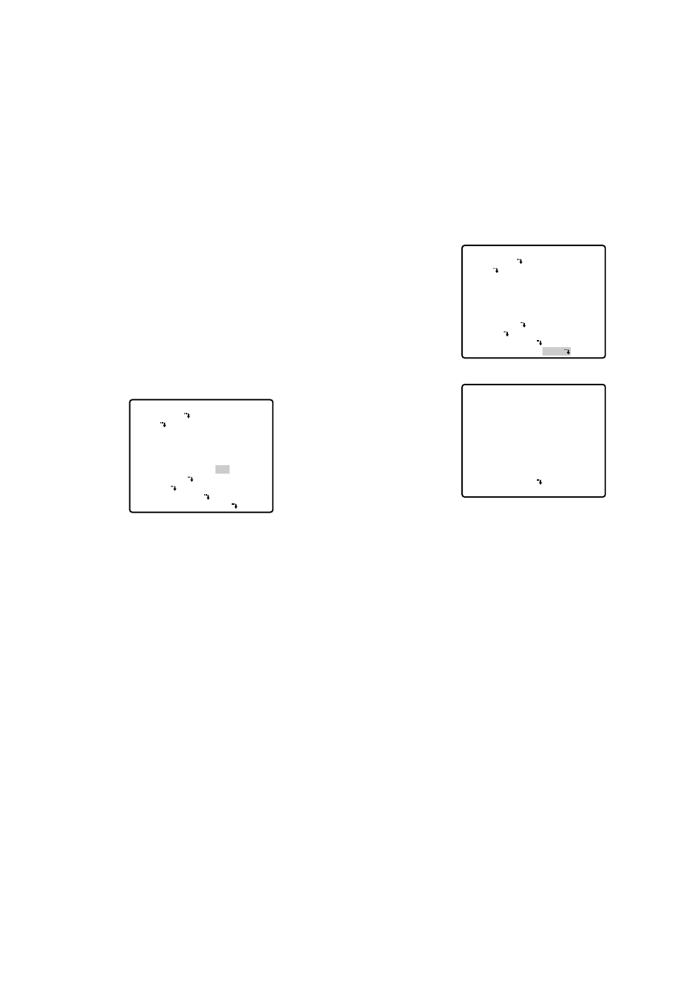
●Password Lock (PASSWORD LOCK)
Caution:
For security, do not operate your VCR for recording
while the password menus are displayed on the
monitor.
A 3-digit number is used for a password to limit
access to all settings.
1. Move the cursor to PASSWORD LOCK, then select
ON or OFF with the joystick.
Note:
ON or OFF can be selected only after going
through the password verification.
OFF: You can change all settings.
ON: You cannot change settings at all nor operate
AUTO PAN, SEQ, SORT, and PATROL.
2. Press the CAM (SET) button.
Password Verification
3. The password verification menu appears.
3-1 Select a numeral for the first digit with the joy-
stick, and press the CAM (SET) button. Though
the entered password is not displayed, the up-
arrow moves one character to the right.
3-2 Repeat the above step for the 2nd and 3rd dig-
its.
Default: 123
3-3 The cursor moves to OK after all the three digits
have been entered. Unless you want to change
the password, press the CAM (SET) button.
If the correct password is entered, the screen
returns to SET UP MENU. ON and OFF settings
are the same as made on the SET UP MENU
menu is as set in step 1.
If a wrong password is entered, the screen
returns to the verification menu. Repeat steps 3-1
to 3-3 to verify the password.
** SET UP MENU **
PRESET 1
MAP
HOME POSITION
SELF RETURN
AUTO MODE
AUTO PAN KEY
DIGITAL FLIP
SPECIAL1
CAMERA
RS485 SET UP
PASSWORD LOCK ON
OFF
OFF
OFF
AUTO PAN
ON
** PASSWORD? **
0 1 2 3 4 5 6 7 8 9
. . .
↑
OK RESET
NEW PASSWORD
RET
-34-
AUTO PAN: Assigns the auto panning function to
the button.
SEQ: Assigns the SEQUENCE function to the but-
ton.
SORT: Assigns the SORT function to the button.
PATROL: Assigns the PATROL PLAY function to the
button.
Note:
AUTO PAN LED on the controller does not light if
something other than AUTO PAN is assigned.
AUTO PAN does not stop with the AUTO PAN
button.
If PASSWORD LOCK is set to ON, you cannot
operate AUTO PAN, SEQ, SORT, and PATROL
even by pressing the AUTO button.
■Digital Flip Setting (DIGITAL FLIP)
Move the cursor to DIGITAL FLIP and select ON or OFF
with the joystick.
OFF: The tilt range is limited from 0° to 90°.
ON: The digital flip function allows the tilt angle to
widen up to 180°. The image on the monitor
screen is flipped horizontally and vertically at the
tilt angle of approx. 135° (If the camera is
installed on a ceiling).
Note:
The tilt range narrows from 0° to 90° if PAN
LIMIT is set to ON.
Notes:
•Digital flip functions while moving the joystick down-
wards. In case of moving the joystick to other direc-
tions, it does not function.
•When OFF is selected for DIGITAL FLIP, the follow-
ing operations are required to move the camera
180° vertically.
1) Move the joystick downwards to aim the camera
down.
2) Move the joystick to the right or left to rotate the
camera 180° horizontally.
3) Move the joystick upwards.
•To set the preset position directly from WV-CU360
System Controller, it is temporarily required to set
both the electronic zoom function and digital flip
function to OFF.
Tilt range setting is disabled between 90° and 185°.
** SET UP MENU **
PRESET 1
MAP
HOME POSITION
SELF RETURN
AUTO MODE
AUTO PAN KEY
DIGITAL FLIP
SPECIAL1
CAMERA
RS485 SET UP
PASSWORD LOCK OFF
OFF
OFF
OFF
AUTO PAN
ON
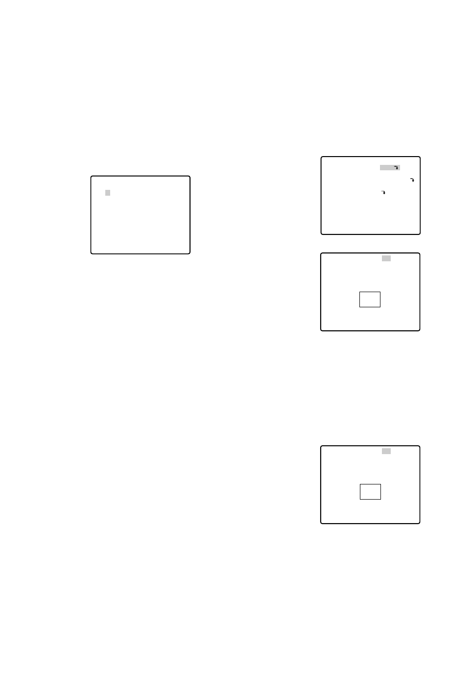
-35-
3-4 To cancel an incomplete password, move the
cursor to RESET, and press the CAM (SET) but-
ton. The screen returns to the verification menu.
3-5 To return to the SET UP MENU menu without ver-
ifying the password, move the cursor to RET, and
press the CAM (SET) button.
New Password
4. To change the password in step 3-3 above, move
the cursor from OK to NEW PASSWORD, then press
the CAM (SET) button. NEW PASSWORD menu
appears.
Note:
The NEW PASSWORD menu is accessible only
after the verification has been completed.
The up-arrow mark appears indicating the first digit
on the first line.
4-1 Enter a new three-digit password in the same
way as in steps 3-1 to 3-2.
4-2 The cursor moves to OK after all the three digits
have been entered. Press the CAM (SET) button
to move the cursor to the first digit on the second
line.
4-3 Enter the same password as the one you have
entered on the first line.
4-4 The cursor moves to OK. Press the CAM (SET)
button. If the new password is successfully
entered, the screen returns to SET UP MENU.
4-5 Retry steps 4-1 to 4-4. If the first entry for the
password is different from the second one, the
screen returns to the NEW PASSWORD? menu.
4-6 To return to the SET UP MENU menu without
changing the password, move the cursor to RET,
and press the CAM (SET) button.
** NEW PASSWORD? **
0 1 2 3 4 5 6 7 8 9
. . .
↑
. . .
OK RESET
RET
■Special 1 Menu Setting
(SPECIAL 1)
●Privacy Zone (PRIVACY ZONE)
Up to 8 unwanted zones can be masked on the monitor
screen.
1. Move the cursor to PRIVACY ZONE and select ON
or OFF with the joystick. Press the CAM (SET) button
to display the ZONE NUMBER setting menu.
ON: Preset privacy zones are veiled on the monitor
screen.
OFF: The veiling function does not work.
2. Select a zone number with the joystick, and press
the CAM (SET) button.
•A zone number followed by * (asterisk) indicates
that the zone has already been registered.
•When a zone number having no * is selected, the
picture is zoomed out (WIDE).
•When a registered zone number is selected, the
camera moves to the preset position. Note that if
you move PAN/TILT, ZOOM/FOCUS or ZONE
SCALE in that position, the registered zone number
having (*) is cancelled.
•The zone frame appears in the center of the screen
if 3 or fewer mask areas exist in that picture and if
the zone number is not registered yet.
•Up to 4 zones can be registered on the fully dis-
played screen (WIDE).
** SPECIAL 1 **
PRIVACY ZONE OFF
PROPO.P/T ON
AREA TITLE ON(USER)
PATROL STOP
ALARM IN/OUT
CLEANING OFF
EL-ZOOM ON
PRESET ALM OFF
IMAGE HOLD OFF
TILT ANGLE 0°
RET
** ZONE NUMBER 1*/8 **
RET
** ZONE NUMBER 1*/8 **
PAN/TILT
→
PUSH SET
ZOOM/FOCUS
→
PUSH SET
ZONE SCALE ••••|••••
SET DEL L H
RET
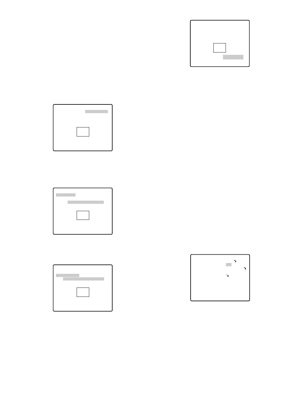
Moving the joystick in the L direction decreases
the zone frame, and moving it in the H direction
increases it. However, the aspect ratio is fixed at
3 to 4.
The privacy zone setting has been completed.
The menu returns to the ZONE NUMBER setting
menu.
3-6
•To complete new settings and repeat other set-
tings, move the cursor to SET and press the
CAM (SET) button. The ZONE NUMBER setting
menu reappears.
•To cancel new settings and return to the SPE-
CIAL 1 menu, move the cursor to DEL and press
the CAM (SET) button. New settings are not reg-
istered.
•To complete new settings and return to the SPE-
CIAL 1 menu, move the cursor to RET and press
the CAM (SET) button.
●Proportional Pan/Tilt (PROPO. P/T)
Move the cursor to PROPO. P/T and select either ON or
OFF with the joystick.
Factory default setting: ON
ON: Pan/tilt speed is in inverse proportion to the
zoom ratio as follows:
Zoom ratio Speed level
x1 7 (fastest)
x2 5
x4 3
x8 1
x15 or more 0 (slowest)
* The speed level values are approximate.
OFF: The speed is constant at the fastest level
regardless of the zoom ratio.
** ZONE NUMBER 3*/8 **
PAN/TILT
→
PUSH SET
ZOOM/FOCUS
→
PUSH SET
ZONE SCALE ••••|••••
SET DEL L H
RET
** SPECIAL 1 **
PRIVACY ZONE OFF
PROPO.P/T ON
AREA TITLE ON(USER)
PATROL STOP
ALARM IN/OUT
CLEANING OFF
EL-ZOOM ON
PRESET ALM OFF
IMAGE HOLD OFF
TILT ANGLE 0°
RET
-36-
•When 5 privacy zones or more are framed on the
displayed screen in the same time, the whole screen
will be masked. In this case, diminish the number of
the zones and set the privacy zones larger.
•The privacy zone may appear on the monitor screen
depending on the direction of the camera.
•The privacy zone function will not work at start-up
immediately after turning the power on.
3. To register a new zone
3-1 For PAN/TILT, move the cursor to PUSH SET and
press the CAM (SET) button.
3-2 Adjust the pan and tilt position so that the
desired position comes into the zone frame with
the joystick.
3-3 For ZOOM/FOCUS, move the cursor to PUSH
SET , and press the CAM (SET) button.
3-4 Adjust zoom and focus, and press the CAM
(SET) button.
Zoom can be adjusted within the range of 1 to 10
magnifications.
3-5 Move the cursor to ZONE SCALE, and move the
joystick to the right or left to adjust the zone
frame. Press the CAM (SET) button after the
adjustment.
** ZONE NUMBER 3*/8 **
PAN/TILT
→
PUSH SET
ZOOM/FOCUS
→
PUSH SET
ZONE SCALE ••••|••••
SET DEL L H
RET
** ZONE NUMBER 3*/8 **
PAN/TILT
→
PUSH SET
ZOOM/FOCUS
→
PUSH SET
U TILT D/L PAN R
ZONE SCALE ••••|••••
SET DEL L H
RET
** ZONE NUMBER 3*/8 **
PAN/TILT
→
PUSH SET
ZOOM/FOCUS
→
PUSH SET
U ZOOM D/L FOCUS R
ZONE SCALE ••••|••••
SET DEL L H
RET
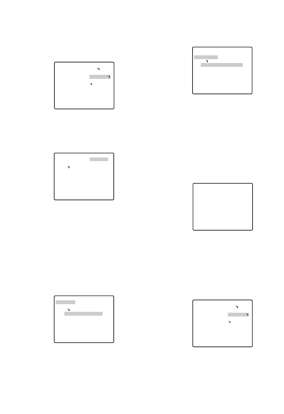
-37-
●Area Title (AREA TITLE)
Up to 8 area titles can be added in specific positions.
1. Select ON (NESW), ON (USER) or OFF with the joy-
stick.
ON (NESW): An area title is displayed for indicating
the camera direction: North (N), North-East (NE),
East (E), South-East (SE), South (S), South-West
(SW), West (W) and North-West (NW).
ON (USER): A user customized area title appears in
a maximum of 16 characters.
OFF: Area title does not appear.
Factory default setting: OFF
2. Press the CAM (SET) button. A submenu appears
except when OFF is selected.
Settings for ON (NESW)
1. Move the cursor to PUSH SET for PAN/TILT, and
press the CAM (SET) button. PAN/TILT is highlight-
ed and "U TILT D/L PAN R" appears.
2. Turn the camera north with the joystick, and press
the CAM (SET) button. The origin of the direction
(North) is set.
Note:
Area titles are highlighted until the origin is set.
** SPECIAL 1 **
PRIVACY ZONE OFF
PROPO.P/T ON
AREA TITLE ON(USER)
PATROL STOP
ALARM IN/OUT
CLEANING OFF
EL-ZOOM ON
PRESET ALM OFF
IMAGE HOLD OFF
TILT ANGLE 0°
RET
→
PUSH SET
→
PUSH SET
** DIRECTION(NESW) **
PAN/TILT
ZOOM/FOCUS
POSI
+
N
RET
→
PUSH SET
→
PUSH SET
→
PUSH SET
** DIRECTION(NESW) **
PAN/TILT
ZOOM/FOCUS
POSI
U TILT D/L PAN R
+
N
RET
3. Move the cursor to PUSH SET for ZOOM/FOCUS,
and press the CAM (SET) button. ZOOM/FOCUS is
highlighted and "U ZOOM D/L FOCUS R" appears.
4. Adjust the zoom or focus with the joystick.
5. Move the cursor to POSI O, and press the CAM
(SET) button. The area title position appears on the
monitor screen. If needed, change the display posi-
tion with the joystick, and press the MON (ESC) but-
ton.
An area title always appears under the camera ID.
If the camera ID and an area title are set to be
shown in separate positions, the area title appears
above the camera ID.
6. Move the cursor to RET, and press the CAM (SET)
button. The SPECIAL 1 menu appears again.
Setting for ON (USER)
If ON (USER) is selected on the SPECIAL 1 menu,
the AREA TITLE (USER) menu appears. The screen
has a number column and title column above RET
and RESET.
Note:
An area number followed by an asterisk * has
already been preset.
→
PUSH SET
→
PUSH SET
** DIRECTION(NESW) **
PAN/TILT
ZOOM/FOCUS
POSI
U ZOOM D/L FOCUS R
+
N
RET
FLOOR 1
N
** SPECIAL 1 **
PRIVACY ZONE OFF
PROPO.P/T ON
AREA TITLE ON(USER)
PATROL STOP
ALARM IN/OUT
CLEANING OFF
EL-ZOOM ON
PRESET ALM OFF
IMAGE HOLD OFF
TILT ANGLE 0°
RET
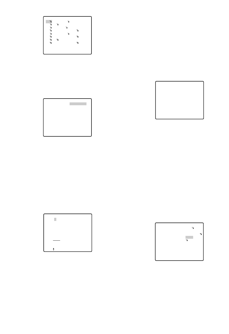
To Quit Editing
•To return to the AREA TITLE menu, move the cursor
to RET, and press the CAM (SET) button.
•To cancel one area title, move the cursor to RESET
in the AREA TITLE menu, and press the CAM (SET)
button.
•To return to the SPECIAL 1 menu, move the cursor
to RET, and press the CAM (SET) button.
•To erase all the area titles, move the cursor to
RESET in the AREA TITLE (USER) selection menu,
and press the CAM (SET) button.
Notes:
•An area title appears under the camera ID if both
are set in the same position. If the setting is dif-
ferent, they appear in the area title position.
•In case of sharing a common subject in a scene
of other camera number, the nearest area title
appears while the camera direction deviates
within 45° from the set position. If two or more
area numbers are set in the same position, the
title of the highest number appears.
●Patrol-learn and Patrol Play (PATROL)
A routine of manual operations can be stored for 1
minute at the maximum and reproduced repetitively.
PATROL
1. Set the following parameters for the patrol-learn
starting position. These parameters are stored when
the patrol-learn mode starts.
•PAN/TILT/ZOOM/FOCUS
•IRIS
•SHUTTER
•AGC
•SENS UP
•WHITE BALANCE
•IMAGE HOLD
•AREA TITLE
FLOOR 1
NORTH
** SPECIAL 1 **
PRIVACY ZONE OFF
PROPO.P/T ON
AREA TITLE ON(USER)
PATROL PLAY
ALARM IN/OUT
CLEANING OFF
EL-ZOOM ON
PRESET ALM OFF
IMAGE HOLD OFF
TILT ANGLE 0°
RET
-38-
1. To select a camera direction, move the cursor to the
desired number, and press the CAM (SET) button.
The direction menu of the selected number appears.
2. Adjust PAN/TILT, ZOOM/FOCUS and display the
position in the same way as AREA TITLE, DIREC-
TION (NESW). See page 37.
3. To add a user-customized title, move the cursor to
the title of the desired number, and press the CAM
(SET) button. The AREA TITLE menu of the selected
number appears.
Area Title Editing
1. Move the cursor to the desired character in the
character field with the joystick, and press the CAM
(SET) button.
2. The selected character appears in the editing field
and the blinking cursor moves one position to the
right.
3. Repeat steps 1 and 2 until one area title is complet-
ed.
4. Move the cursor to POSI O, and press the CAM
(SET) button. The area title appears on the monitor
screen. If needed, change the display position with
the joystick, and press the MON (ESC) button.
** AREA TITLE(USER) **
NORTH
2
3 EAST
4 SOUTH-EAST
5 SOUTH
6 SOUTH-WEST
7
8 NORTH-WEST
RET RESET
1*
→
PUSH SET
→
PUSH SET
** DIRECTION(USER) 1 **
PAN/TILT
ZOOM/FOCUS
+
NORTH
RET DEL
AREA TITLE 1*
0123456789
ABCDEFGHIJKLM
NOPQRSTUVWXYZ
().,'":;&#!?=
+-*/%$
SPACE
POSI RET RESET
................

-39-
•DIGITAL FLIP
•PRIVACY ZONE
•CAMERA ID
•PROPO.PT
•PAN LIMIT
•ZOOM LIMIT
•TILT ANGLE
•CLEANING
After starting the patrol-learn, the following manual
operations are stored.
•PAN/TILT/ZOOM/FOCUS operation
•IRIS operation
•Preset positioning
The auto focus function is disabled during the patrol
operation. Under such circumstances, the camera
goes out of focus when zooming in with WIDE
selected resulting from a characteristic of a zoom
lens. For storing the zoom operation, start with the
TELE mode keeps the camera in focus.
The patrol operation ranges from the horizontal
direction to the downward direction. The digital flip
function is disabled (page 34).
2. Open the SET UP menu and move the cursor to
SPECIAL 1. For PATROL, select LEARN, PLAY or
STOP with the joystick.
The factory default setting is STOP.
LEARN: A series of manual operations is stored.
PLAY: Stored operations are reproduced.
STOP: LEARN or PLAY is not activated.
PATROL LEARN with a Controller Having PATROL
Button
1. Press the PATROL button and the CAM (SET) button
simultaneously to start patrol-learn. The setup menu
displays "LEARNING(60S)", and the starting points
are stored. (unit: s)
2. Operate patrol-learn manually. The operation data is
stored. The countdown to complete learning is dis-
played.
3. To stop patrol-learn, press the PATROL STOP but-
ton.
Patrol-learn with a Controller not Having the
PATROL Button
1. Close the SET UP or SPECIAL 1 menu to start
PATROL LEARN. Starting point parameters are
stored and "LEARNING(60S)" is displayed on the
monitor.
LEARNING(60S)
2. Operate patrol-learn manually.
3. Open the SET UP menu to stop learning.
Notes:
•It is recommended to set PAN LIMIT to ON for
patrol-learn. Otherwise PAN LIMIT is invalid in
playback.
•If the power fails in the patrol-learn mode, start
the patrol-learn function again from the starting
point.
•LEARN also stops 1 minute after starting if the
memory is full.
•Auto refreshing may be activated in the patrol
play mode or the auto mode to calibrate the lens
position.
Patrol Play with a Controller Having the PATROL
Button
1. Press the PATROL PLAY button. The camera turns
to the starting point and reproduces the operations
stored in the memory. Iris operation is valid only in
the playback mode.
2. Press the PATROL STOP button and PROGRAM
button simultaneously to stop playback or press any
manual operation button (e.g., PAN/TILT/ ZOOM/
FOCUS) except the iris buttons.
Patrol Play with a Controller not Having the PATROL
Button
1. Select patrol play in the setup menu, and then close
the menu. The camera turns to the starting point and
the operations stored in memory are reproduced.
Iris operation is valid only in the playback mode.
2. Open the SET UP menu, or press any of manual
operation button (e.g., PAN/TILT/ZOOM/FOCUS)
except the iris buttons to stop playback.
Patrol Play with the AUTO PAN Button
1. If the PATROL PLAY function is assigned to the
AUTO PAN button, press the AUTO PAN button to
turn the camera back to the starting point and to
reproduce the operation data stored in the memory.
2. To stop playback, press the PATROL STOP button
or any manual operation button (e.g., PAN/TILT/
ZOOM/FOCUS) except the iris buttons.
Notes:
•In the patrol play mode, the camera movement may
occasionally deviate from the entered routine when
the routine includes a move to a preset position. If
this happens, re-enter the routine of manual opera-
tions for patrol-learn.
•In the patrol play mode, black and white automatic
switching does not work.
•In the patrol play mode, when the power of the con-
troller is turned on or off, the patrol play stops. In this
case, press the PATROL PLAY button again. (If
SELF RETURN is set to ON, the patrol play will start
again after elapsing the setting return time.)

CNT-CLS 1, 2 (Output)
Two contact closure signals (Open collector type) are
output through the Alarm Output connector.
1. Move the cursor to CNT-CLS 1, and select OFF,
ALARM or AUX 1 with the joystick.
The factory default setting is OFF.
When ALARM is selected, TIME OUT appears.
Select an appropriate duration from among 100 MS,
200 MS, 1000 MS (1 s), 2000 MS (2 s) and 4000 MS
(4 s) with the joystick. (unit: s)
The factory default setting is 100 MS. (unit: ms)
Note:
The shorter the duration, the more frequent will
be the detection output.
2. Move the cursor to CNT-CLS 2, then select OFF,
AUX 2 with the joystick.
The factory default setting is OFF.
OFF: Contact closure signals are deactivated.
ALARM: Available for CNT-CLS 1 only. A motion
detection signal is output.
AUX 1(2): An alarm signal is output when the cam-
era receives a command from the controller.
Note:
It is recommended to set the connected external
device to ignore the shorter alarm outputs of 90
ms or less from the camera.
COAXIAL ALARM OUT
Alarm output signals are supplied through the coaxial
cable.
1. Move the cursor to COAX ALM OUT and select ON
or OFF.
2. Press the CAM (SET) button.
The factory default setting is OFF.
ON: The camera sends an alarm output signal after
it turns to a preset position.
OFF: The camera does not send an output signal.
Notes:
•The camera ignores alarm inputs during manual
operation.
•To download or upload preset data to the system
controller, select “OFF”.
-40-
●Alarm Input/Output (ALARM IN/OUT)
Move the cursor to ALARM IN/OUT, and press the CAM
(SET) button. The ALARM IN/OUT submenu appears.
Note:
While the camera is in the AF mode or the lens
moves between WIDE and TELE, alarm input may
be ignored if several alarm inputs are received in
succession.
ALARM IN 1-4
Alarm input signals are supplied from external devices
through the ALARM IN connector to turn the camera to
a preset position.
1. Move the cursor to ALARM IN 1* and select a preset
position or OFF with the joystick, then press the
CAM (SET) button.
The factory default setting is OFF.
*Set ALARM IN 2, 3 and 4 in the same way as
ALARM IN 1.
1 POSI, 2 POSI, 3 POSI and 4 POSI: Preset posi-
tion. If an alarm input is received, the camera
turns to a preset position, and sends an alarm
output signal. The position number corresponds
to the alarm input number (1-1, 2-2, 3-3 and 4-4).
OFF: The camera ignores alarm inputs.
** SPECIAL 1 **
PRIVACY ZONE OFF
PROPO.P/T ON
AREA TITLE ON(USER)
PATROL STOP
ALARM IN/OUT
CLEANING OFF
EL-ZOOM ON
PRESET ALM OFF
IMAGE HOLD OFF
TILT ANGLE 0°
RET
** ALARM IN/OUT **
ALARM IN 1
ALARM IN 2
ALARM IN 3
ALARM IN 4
CNT-CLS 1
TIME OUT
CNT-CLS 2
COAX ALM OUT
RET
OFF
OFF
OFF
OFF
OFF
100MS
OFF
OFF
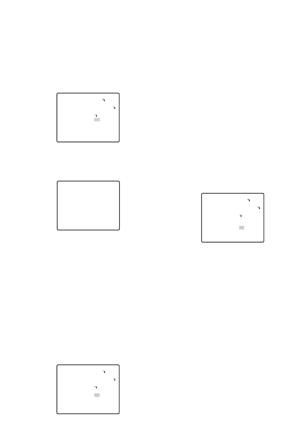
-41-
●Cleaning (CLEANING)
With CLEANING in the ON position, the camera’s built-
in electromechanical contacts are cleaned at regular
intervals (approx. every 7 days).
A dry contact adversely affects picture quality and
motors operation.
1. Move the cursor to CLEANING and select ON or
OFF with the joystick.
ON: The contacts are cleaned for approx. 1 minute.
"CLEANING" disappears when the cleaning
process is completed.
OFF: No contact cleaning.
Note:
To download or upload preset data to the system
controller, set the cleaning function to “OFF”. If
the cleaning function is activated during the
uploading or downloading process, the upload-
ing or downloading fails.
●Electronic Zoom (EL-ZOOM)
The electronic zoom magnifies a scene 10-fold. With a
22-fold optical zoom lens, the camera is capable of
220-fold zoom.
1. Move the cursor to EL-ZOOM and select ON or OFF
with the joystick, and then press the CAM (SET) but-
ton.
** SPECIAL 1 **
PRIVACY ZONE OFF
PROPO.P/T ON
AREA TITLE ON(USER)
PATROL STOP
ALARM IN/OUT
CLEANING ON
EL-ZOOM ON
PRESET ALM OFF
IMAGE HOLD OFF
TILT ANGLE 0°
RET
CLEANING
** SPECIAL 1 **
PRIVACY ZONE OFF
PROPO.P/T ON
AREA TITLE ON(USER)
PATROL STOP
ALARM IN/OUT
CLEANING ON
EL-ZOOM ON
PRESET ALM OFF
IMAGE HOLD OFF
TILT ANGLE 0°
RET
ON: 10 - fold electronic zoom is available with the
ZOOM switch on the controller.
OFF: The electronic zoom function is not used.
Notes:
•A scene magnified by the electronic zoom func-
tion may be inferior in picture quality to a non-
magnified one.
•The electronic zoom does not function in the pre-
set position setting mode.
•When trying to set preset positions directly from
the WV-CU360 System Controller while ON is set
for the electronic zoom function and the dis-
played scene is magnified at more than x22, the
INHIBIT indication will be displayed. In this case,
you need to set the electronic zoom function
temporarily to OFF.
●Preset Alarm (PRESET ALM)
An alarm output is sent when the camera moves to the
designated position depending on the mode.
1. Move the cursor to PRESET ALM and select ON or
OFF.
ON: Alarm signals are output in the following cases.
•When a preset positioning sequence is complet-
ed while AUTO MODE is set to SEQ.
•When a preset positioning sequence is complet-
ed while AUTO MODE is set to SORT.
•When the self-return function has returned the
camera to its home position.
•Positioning is completed for a position request
command.
•Positioning to the designated point is completed
for ALARM IN/OUT.
•When positioning to the starting point is complet-
ed while AUTO MODE is set to AUTO PAN.
•When positioning to the starting point is complet-
ed while PATROL is set to PLAY.
OFF: Alarm signals are not output.
Notes:
•Select OFF when the camera downloads or
uploads the preset data.
•When selecting "ON", set "AUTO" for "ALARM
DATA" on the RS485 SETUP menu (page 19).
** SPECIAL 1 **
PRIVACY ZONE OFF
PROPO.P/T ON
AREA TITLE ON(USER)
PATROL STOP
ALARM IN/OUT
CLEANING OFF
EL-ZOOM ON
PRESET ALM ON
IMAGE HOLD OFF
TILT ANGLE 0°
RET
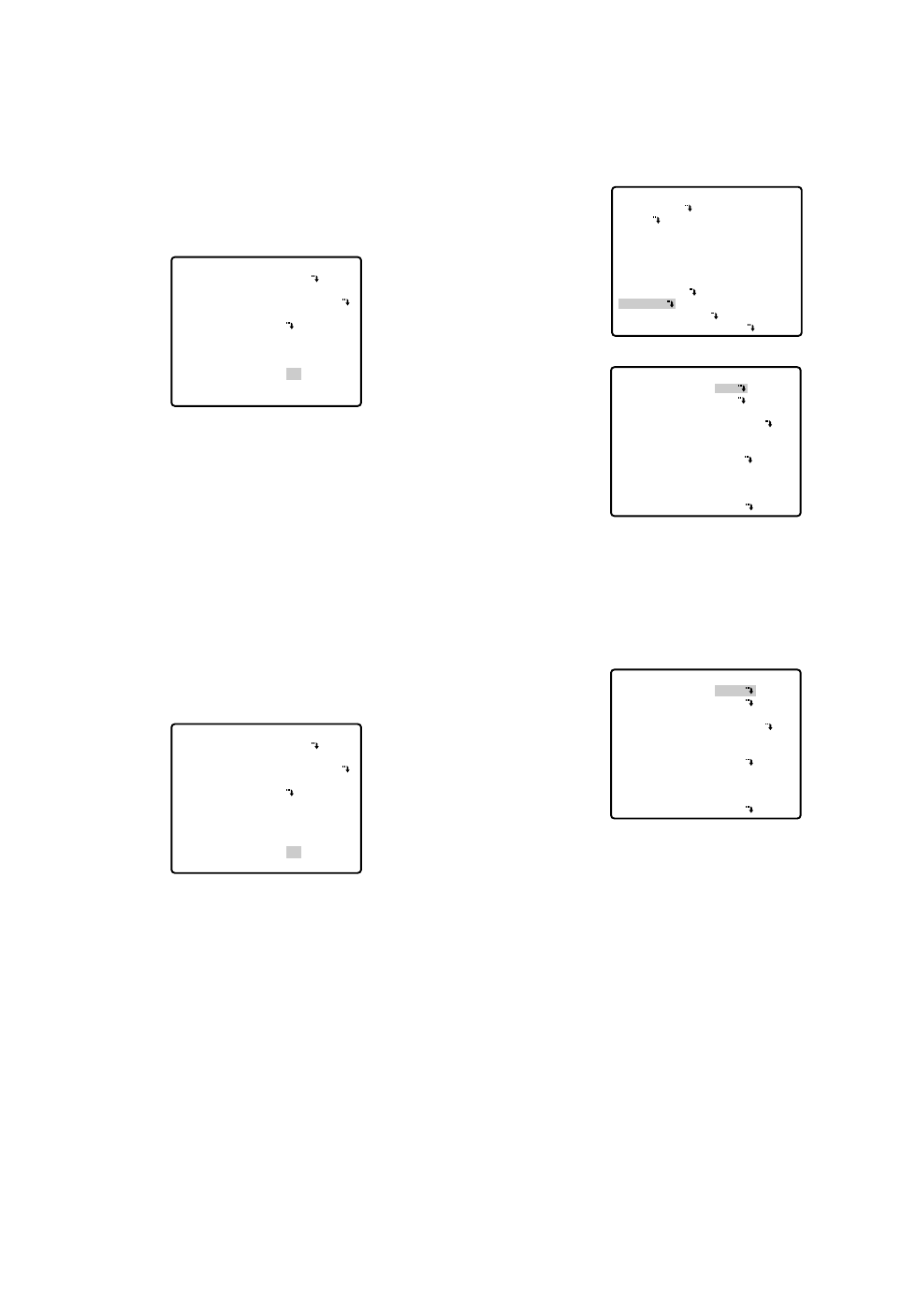
■Camera Setting
●To Display the Camera Setting Menu
Move the cursor to CAMERA O, and press the CAM
(SET) button. The camera setting menu appears.
●Camera Identification (CAMERA ID)
1. Move the cursor to CAMERA ID, and select ON to
display the camera identification with the joystick.
2. Follow the steps below to edit the camera ID char-
acters.
2-1 Move the cursor to CAMERA ID and press the
CAM (SET) button to display the character edit-
ing menu.
2-2 Move the cursor to the character you want to edit
or change with the joystick, and press the CAM
(SET) button. The selected character appears in
the editing area.
2-3 Repeat the steps above until all characters are
edited.
3. After editing the camera identification characters,
follow the steps below to decide the position of
CAMERA ID.
3-1 Move the cursor to POSI, and press the CAM
(SET) button to display the ID position menu.
** SET UP MENU **
PRESET 1
MAP
HOME POSITION
SELF RETURN
AUTO MODE
AUTO PAN KEY
DIGITAL FLIP
SPECIAL1
CAMERA
RS485 SET UP
PASSWORD LOCK OFF
OFF
OFF
OFF
AUTO PAN
ON
** SET UP **
CAMERA ID
ALC/MANUAL
SHUTTER
AGC
SENS UP
SYNC
WHITE BAL
MOTION DET
AF MODE
RET SPECIAL2
ALC
AUTO
ON(MID)
OFF
INT
ATW1
OFF
AUTO L
OFF
** SET UP **
CAMERA ID
ALC/MANUAL
SHUTTER
AGC
SENS UP
SYNC
WHITE BAL
MOTION DET
AF MODE
RET SPECIAL2
ON
ALC
AUTO
ON(MID)
OFF
INT
ATW1
OFF
AUTO L
-42-
●Image Hold (IMAGE HOLD)
The camera picture remains as a still image on the
monitor screen until the camera reaches the preset
position. This function is useful for surveillance via local
area network.
1. Move the cursor to IMAGE HOLD and select ON or
OFF.
ON: The last displayed still image is shown till the
camera finishes moving to a preset position.
However, the still image may be distorted with
the effect of panning or tilting.
OFF: The current image is being displayed while the
camera is moving to a preset position.
●Tilt Angle (TILT ANGLE 0 °/5 °)
You can select the tilting range.
1. Move the cursor to TILT ANGLE and select 0° or 5°.
0°:The tilting range is between 0° and 180°.
5°:The tilting range is between –5° and 185°.
Note:
When 5° is selected in the WIDE mode, a sub-
ject is not displayed on approximately the upper
half of the screen or the screen becomes white
for some subjects due to the AGC effect.
** SPECIAL 1 **
PRIVACY ZONE OFF
PROPO.P/T ON
AREA TITLE ON(USER)
PATROL STOP
ALARM IN/OUT
CLEANING OFF
EL-ZOOM ON
PRESET ALM OFF
IMAGE HOLD ON
TILT ANGLE 0°
RET
** SPECIAL 1 **
PRIVACY ZONE OFF
PROPO.P/T ON
AREA TITLE ON(USER)
PATROL STOP
ALARM IN/OUT
CLEANING OFF
EL-ZOOM ON
PRESET ALM OFF
IMAGE HOLD ON
TILT ANGLE 0°
RET
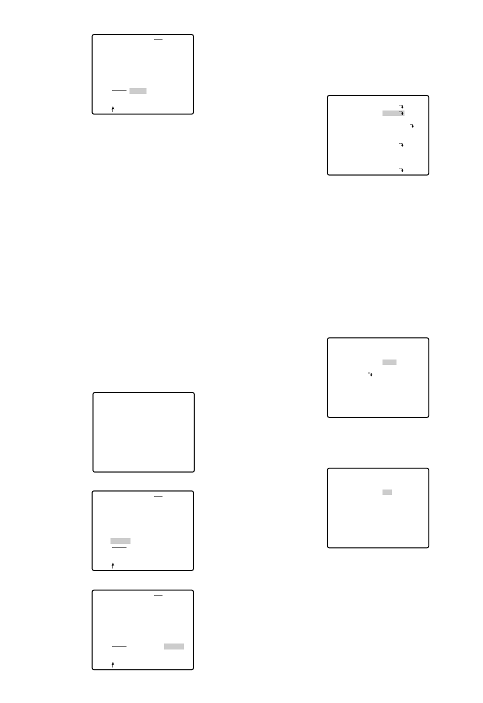
CAM1
CAMERA ID
0123456789
ABCDEFGHIJKLM
NOPQRSTUVWXYZ
().,'":;&#!?=
+-*/%$
SPACE
POSI RET RESET
CAM1............
CAMERA ID
0123456789
ABCDEFGHIJKLM
NOPQRSTUVWXYZ
().,'":;&#!?=
+-*/%$
SPACE
POSI RET RESET
CAM1............
-43-
3-2 Decide the position of the camera ID with the joy-
stick. Press the MON (ESC) button to fix the posi-
tion, and return to the character editing menu.
Notes:
•When you want the pointer to move to a specific
character in the editing area, select a new char-
acter, and press the CAM (SET) button. This
function allows you to edit or correct a specific
character.
•To enter a blank space into the camera ID, move
the cursor to SPACE, and press the CAM (SET)
button.
•To erase all characters in the editing area, move
the cursor to RESET, and press the CAM (SET)
button.
•The positioning of CAMERA ID stops at the
edges of the screen.
•CAMERA ID moves faster when the joystick is
kept at the right or left for one second or more.
•Move the cursor to RET to return to the SET UP
menu, and press the CAM (SET) button.
CAMERA ID
0123456789
ABCDEFGHIJKLM
NOPQRSTUVWXYZ
().,'":;&#!?=
+-*/%$
SPACE
POSI RET RESET
CAM1............
●Light Control Setting (ALC/MANUAL)
1. Move the cursor to ALC/MANUAL and select ALC or
MANUAL with the joystick. When you select ALC,
set backlight compensation.
Note:
The backlight compensation submenu associat-
ed with this menu is described separately and
should be set up after installing the camera at
the site and observing the actual site picture.
2. When MANUAL is selected, quit the setup menu by
pressing the MON (ESC) button. Press the OPEN or
CLOSE button on the controller for iris adjustment.
(1) ALC Mode with BLC ON
1. Press the CAM (SET) button after selecting ALC.
The ALC CONT menu appears.
2. Move the cursor to the BLC parameter and select
ON.
3. If you want to adjust the video output level, move the
"I" cursor for LEVEL. Adjust it to the desired level
with the joystick.
4. Move the cursor to RET and press the CAM (SET)
button to return to the CAM SET UP menu.
** SET UP **
CAMERA ID
ALC/MANUAL
SHUTTER
AGC
SENS UP
SYNC
WHITE BAL
MOTION DET
AF MODE
RET SPECIAL2
OFF
ALC
AUTO
ON(MID)
OFF
INT
ATW1
OFF
AUTO L
** ALC CONT **
BACK LIGHT COMP
BLC
MASK SET
LEVEL
RET
OFF
••••|••••
- +
** ALC CONT **
BACK LIGHT COMP
BLC
LEVEL
RET
ON
••••|••••
- +
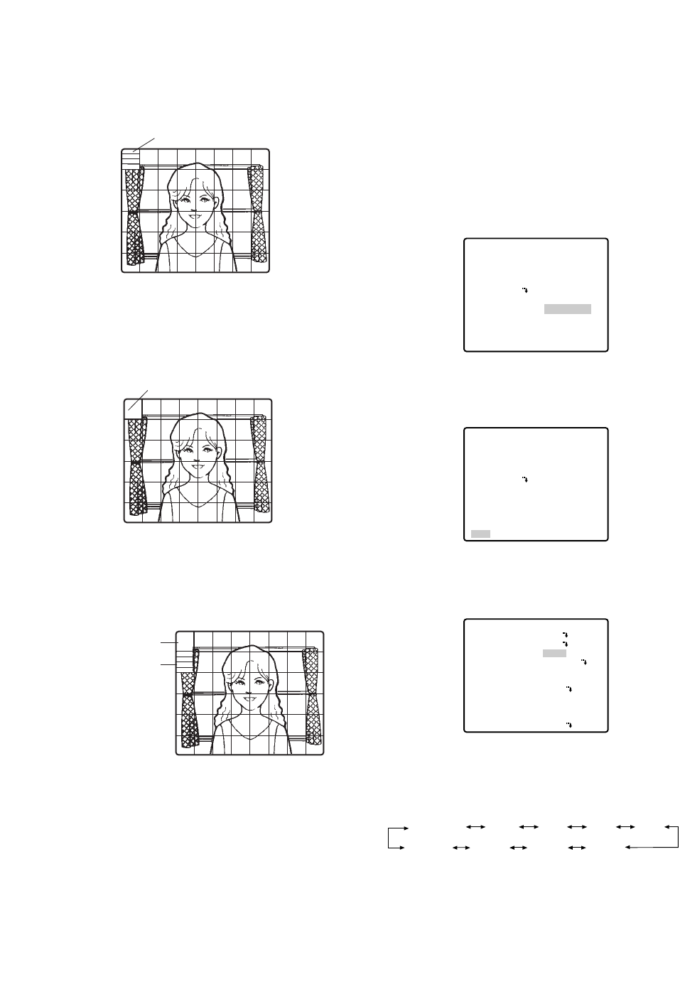
6. If you want to change the picture contrast, move the
"I" cursor for LEVEL and adjust the level.
Note:
If operation of the controller's IRIS (OPEN, CLOSE)
buttons during operation is done after the menu is
closed, the LEVEL on the CAMERA menu is reflect-
ed and stored for these settings. However, if the
camera is in a preset position, it is reflected as a
parameter of the preset position. To return to the ini-
tial factory default level, hold down the system con-
troller's Abutton.
7. Move the cursor to RET and press the CAM (SET)
button to return to the CAM SET UP menu.
●Shutter Speed Setting (SHUTTER)
Move the cursor to SHUTTER and select the elec-
tronic shutter speed with the joystick. The electronic
shutter speed changes as follows with the joystick:
** ALC CONT **
BACK LIGHT COMP
BLC
MASK SET
LEVEL
RET
OFF
••••|••••
- +
** ALC CONT **
BACK LIGHT COMP
BLC
MASK SET
LEVEL
RET
OFF
••••|••••
- +
** SET UP **
CAMERA ID
ALC/MANUAL
SHUTTER
AGC
SENS UP
SYNC
WHITE BAL
MOTION DET
AF MODE
RET SPECIAL2
OFF
ALC
AUTO
ON(MID)
OFF
INT
ATW1
OFF
AUTO L
OFF (1/60) 1/100AUTO
1/10 000 1/4 000 1/2 000 1/1 000
1/250 1/500
-44-
(2) ALC Mode with BLC OFF
1. Move the cursor to BLC and select OFF. (When you
select MANUAL, BLC is not available.) MASK SET
appears on the menu.
2. Move the cursor to MASK SET and press the CAM
(SET) button. The 48 mask areas appear on the
monitor screen. The cursor is blinking in the top left
corner of the screen.
3. To mask an area where backlight is bright, move the
cursor to the area and press the CAM (SET) button.
The mask turns white. Repeat this procedure to
mask the desired areas.
4. To cancel a masked area, move the cursor to the
area, and press the CAM (SET) button. To cancel all
masking areas, press the F3 button of WV-CU650.
For WV-RM70, press the right and left switches
simultaneously.
5. After masking is completed, press the MON (ESC)
button. The 48 mask areas on the monitor screen
disappear and the ALC CONT menu appears.
Blinking
Blinking
Blinking
Turns to white
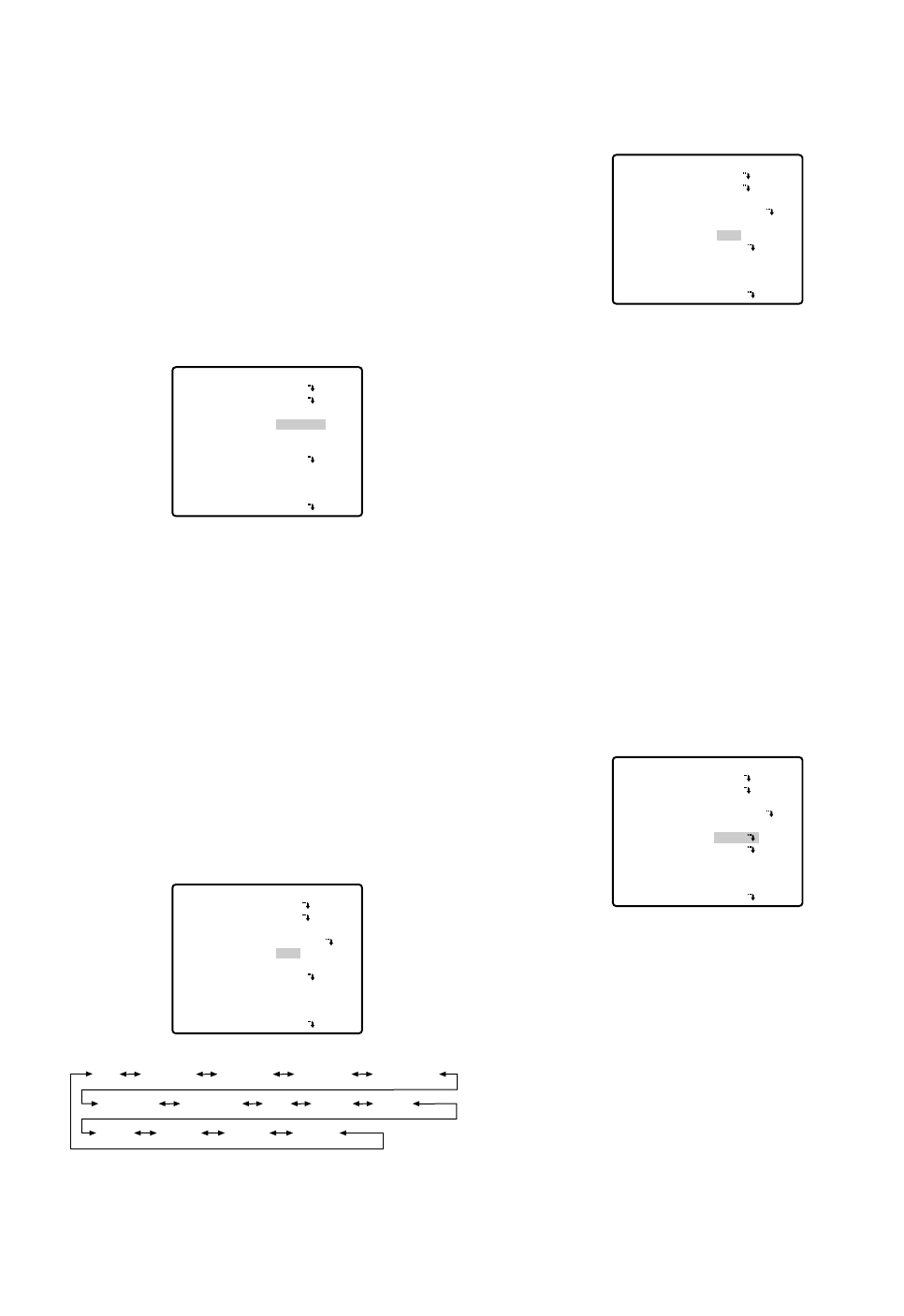
-45-
•In the AUTO mode, an object is clearly imaged
under highlighted conditions by using the combina-
tion technology of iris and shutter functions.
Note:
When the selected shutter speed caused flicker
on condition that fluorescent lamps stay on,
change this setting to 'OFF'.
●Gain Control [AGC ON (LOW/ MID/
HIGH)/OFF]
Move the cursor to AGC and select ON (LOW), ON
(MID), ON (HIGH) or (OFF) with the joystick.
Notes:
•Even if AGC is set to ON and if the noise reduction
function is enabled, afterimages may be produced
by shooting a moving object or by panning or tilting
the camera.
•For more information, refer to Digital Noise
Reduction on page 49.
●Electronic Sensitivity Enhancement
(SENS UP)
Move the cursor to SENS UP and select the desired
electronic sensitivity enhancement mode with the joy-
stick. The electronic sensitivity enhancement mode
changes as follows with the joystick:
Note:
While the SENS UP function is selected, noise or
spots may appear in the picture when the sensitivity
of the camera is increased. This is a normal phe-
nomenon.
** SET UP **
CAMERA ID
ALC/MANUAL
SHUTTER
AGC
SENS UP
SYNC
WHITE BAL
MOTION DET
AF MODE
RET SPECIAL2
OFF
ALC
AUTO
ON(MID)
OFF
INT
ATW1
OFF
AUTO L
** SET UP **
CAMERA ID
ALC/MANUAL
SHUTTER
AGC
SENS UP
SYNC
WHITE BAL
MOTION DET
AF MODE
RET SPECIAL2
OFF
ALC
AUTO
ON(MID)
OFF
INT
ATW1
OFF
AUTO L
X2 AUTO
OFF X4 AUTO X6 AUTO X10 AUTO
X16 AUTO X32 AUTO X2 FIX
X6 FIX X10 FIX X16 FIX X32 FIX
X4 FIXOFF
●Synchronization (SYNC)
Move the cursor to SYNC and select LL or INT with the
joystick.
Important Notices:
1. The priorities of SYNC modes are assigned as fol-
lows:
1. Multiplexed vertical drive (VD2) (highest priority)
2. Line-lock (LL)
3. Internal sync (INT) (lowest priority)
2. To use internal sync, select INT.
3. Whenever the vertical drive pulse (VD2) is supplied
to the camera, the camera sync mode is automati-
cally switched to the multiplexed vertical drive pulse
(VD2) regardless of the selected sync mode.
Line-lock Sync Mode (LL)
1. Move the cursor to SYNC and select LL with the joy-
stick. The LL sync mode is not available when the
multiplexed vertical drive (VD2) pulse is supplied.
2. After selecting LL, press the CAM (SET) button.
The SYNC menu appears on the monitor screen.
3. Supply the video output signal of the camera to be
adjusted and the reference video output signal to a
dual-trace oscilloscope.
4. Set the dual-trace oscilloscope to the vertical rate
and expand the vertical sync portion on the oscillo-
scope.
** SET UP **
CAMERA ID
ALC/MANUAL
SHUTTER
AGC
SENS UP
SYNC
WHITE BAL
MOTION DET
AF MODE
RET SPECIAL2
OFF
ALC
AUTO
ON(MID)
OFF
INT
ATW1
OFF
AUTO L
** SET UP **
CAMERA ID
ALC/MANUAL
SHUTTER
AGC
SENS UP
SYNC
WHITE BAL
MOTION DET
AF MODE
RET SPECIAL2
OFF
ALC
AUTO
ON(MID)
OFF
LL
ATW1
OFF
AUTO L
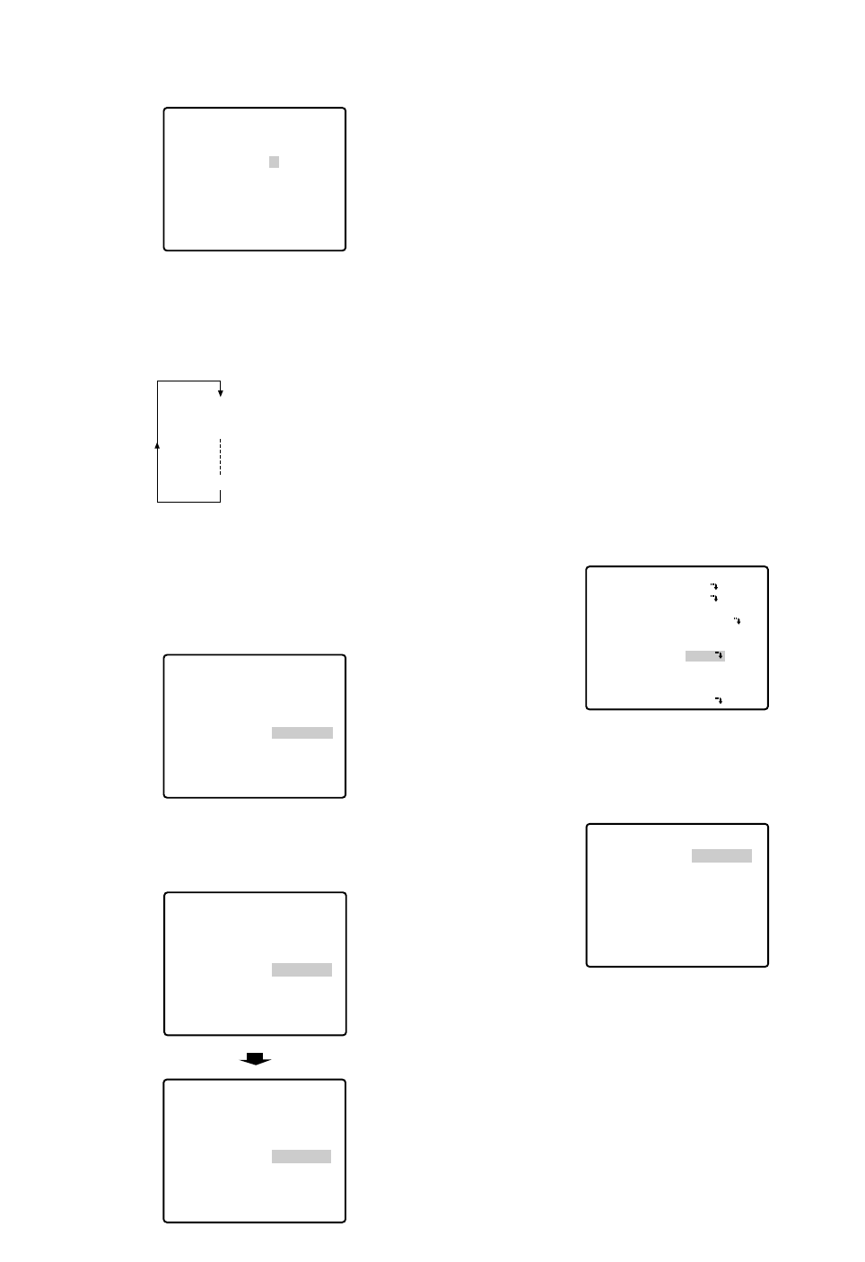
5. Move the cursor to COARSE with the joystick.
6. Match the vertical phases for both video output sig-
nals as closely as possible with the joystick. The
coarse adjustment can be performed in steps of
22.5 degrees (16 steps) with the joystick.
Note:
After the 16th step, the adjustment level returns
to the first step.
7. Move the cursor to FINE by using the joystick.
8. Match the vertical phase for both video output sig-
nals as closely as possible with the joystick.
Notes:
•When the "|" cursor reaches the "+" end, it jumps
back to "–". At the same time, COARSE is incre-
mented by one step to enable a continuous
adjustment. The reverse takes place when the "|"
cursor reaches the "–" end.
•When the joystick is kept at the right or left for
one second or more, the "|" cursor moves quick-
ly.
•To reset COARSE and FINE to the preset values,
press the F3 button of WV-CU650. For WV-RM70,
press the right and left switches simultaneously.
COARSE is preset to zero-crossing of the AC line
phase.
•If the AC line phase contains spike noise, etc.,
the vertical phase of the video output signal may
be disturbed.
●White Balance (WHITE BAL)
(1) Auto-Tracing White Balance Mode (ATW1/ ATW2)
1. Move the cursor to WHITE BAL and select ATW1
with the joystick. The white balance of the camera is
automatically adjusted.
2. For fine adjustment of ATW1/ATW2, press the CAM
(SET) button. The ATW1/ATW2 fine adjustment
menu appears on the monitor screen.
3. Move the cursor to RET with the joystick and press
the CAM (SET) button to return to the SET UP menu.
** SYNC **
V PHASE
COARSE
FINE
RET
4(1--16)
- +
** SYNC **
V PHASE
COARSE
FINE
RET
1(1--16)
- +
••••••|••
•|•••••••
** SET UP **
CAMERA ID
ALC/MANUAL
SHUTTER
AGC
SENS UP
SYNC
WHITE BAL
MOTION DET
AF MODE
RET SPECIAL2
OFF
ALC
AUTO
ON(MID)
OFF
INT
ATW1
OFF
AUTO L
** ATW1 **
R
B
RET
••••|••••
- +
••••|••••
- +
-46-
** SYNC **
V PHASE
COARSE
FINE
RET
1(1--16)
•|•••••••
- +
1 (1 - - - 16): 0 degrees
2 (1 - - - 16): 22.5 degrees
16 (1 - - - 16): 337.5 degrees
** SYNC **
V PHASE
COARSE
FINE
RET
1(1--16)
•|•••••••
- +
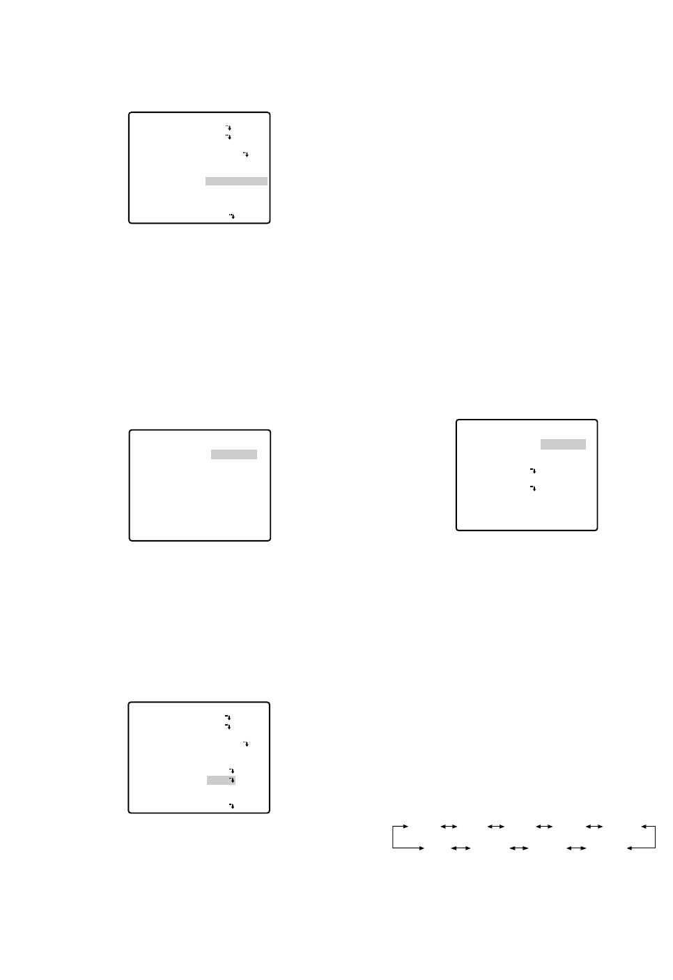
-47-
(2) Automatic White Balance Control Mode (AWC)
1. Move the cursor to WHITE BAL and select AWC →
PUSH SET with the joystick.
2. Press the CAM (SET) button to start the white bal-
ance setup. PUSH SET is highlighted to indicate that
white balance is being set.
3. PUSH SET returns to normal when balance setting is
completed.
4. For fine adjustment of the AWC, move the cursor to
AWC and press the CAM (SET) button. The AWC
fine adjustment menu appears on the monitor
screen.
5. Move the cursor to RET with the joystick and press
the CAM (SET) button to return to the SET UP menu.
●Motion Detector (MOTION DET)
1. Move the cursor to MOTION DET and select ON or
OFF with the joystick.
2. If ON is selected, press the CAM (SET) button. The
MOTION DETECT menu appears.
You can mask the areas in this menu.
** SET UP **
CAMERA ID
ALC/MANUAL
SHUTTER
AGC
SENS UP
SYNC
WHITE BAL
MOTION DET
AF MODE
RET SPECIAL2
OFF
ALC
AUTO
ON(MID)
OFF
INT
AWC
→
PUSH SET
OFF
AUTO L
** AWC **
R
B
RET
••••|••••
- +
••••|••••
- +
3. Move the cursor to MASK SET and press the CAM
(SET) button. 48 mask areas appear on the monitor
screen.
Refer to Light Control Setting on page 43 for mask-
ing operations.
4. After masking areas, press the MON (ESC) button.
The MOTION DETECT menu appears on the monitor
screen.
5. Move the cursor to ALARM and select ON or OFF
with the joystick.
ON: The alarm signal is supplied while the display
mode is activated.
OFF: The alarm signal is not supplied while the dis-
play mode is activated.
6. Move the cursor to DISPLAY MODE.
Press the CAM (SET) button to see the present set-
ting. The areas that detect the motions blink.
7. Move the cursor to LEVEL with the joystick.
Obtain the optimum detection level with the joystick.
Note:
Repeat the above procedure until you obtain the
adjusted results.
8. Dwell Time
Move the cursor to DWELL TIME, and select a time
with the Joystick.
When the time specified here elapses after motion
detection, the camera will notify the connected
device of the alarm activation. The default setting is
2 seconds.
Selectable times (unit: s): 2S, 5S, 10S, 30S
9. Move the cursor to RECOVER TIME with the joystick.
You can select the following recover times. (unit:
min)
** SET UP **
CAMERA ID
ALC/MANUAL
SHUTTER
AGC
SENS UP
SYNC
WHITE BAL
MOTION DET
AF MODE
RET SPECIAL2
OFF
ALC
AUTO
ON(MID)
OFF
INT
ATW1
ON
AUTO L
** MOTION DETECT **
LEVEL
DWELL TIME 2S
DISPLAY MODE
ALARM OFF
MASK SET
RECOVER TIME
RET
••••|••••
- +
1MIN
2MIN 3MIN 5MIN 10MIN
60MIN 30MIN 20MIN
1MIN
OFF
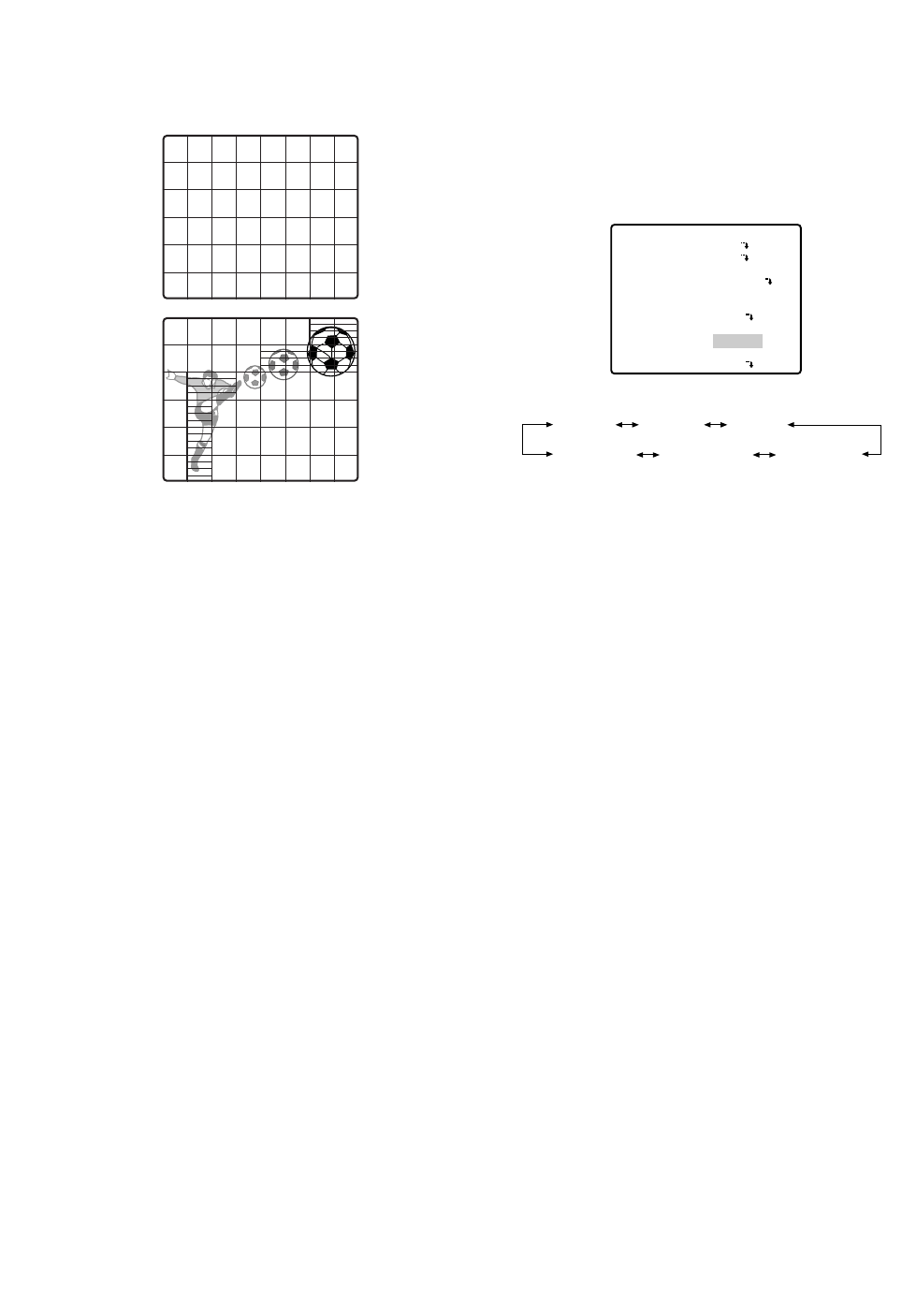
●Auto Focus Setting (AF MODE)
1. Move the cursor to AF MODE, and select the follow-
ing mode with the joystick. S, M and L stand for
Small, Middle and Large areas respectively in the
center of a scene that are used for sensing sharp-
ness in auto-focusing.
MANUAL S, M, L: Auto focus is activated only when
the button that is assigned for the auto-focus
function on the controller is pressed.
AUTO S, M, L: Auto focus is activated automatically
while the pan, tilt or zoom operation is manually
performed. These may be selected in the same
way as MANUAL by pressing the button that is
assigned for the auto-focus function on the con-
troller.
2. To confirm auto-focus operation, press CAM (SET)
button.
Notes:
•When the electronic sensitivity enhancement (SENS
UP) is activated except in the x2 FIX or x2 AUTO
mode, this function is automatically set to MANUAL
(S, M, L).
•The auto focus lens does not function properly in the
AUTO mode after using the WIDE lens.
•The auto focus lens may not function properly in the
AUTO mode under the following conditions.
1. Dirt or water on window glass.
The auto focus may focus on the dirt or water.
2. Low lighting or illumination.
3. Bright objects or high intensity objects.
4. Single color object such as a white wall or fine
felt
5. No center objects and sloping objects
6. Far and near objects on the screen
** SET UP **
CAMERA ID
ALC/MANUAL
SHUTTER
AGC
SENS UP
SYNC
WHITE BAL
MOTION DET
AF MODE
RET SPECIAL2
OFF
ALC
AUTO
ON(MID)
OFF
INT
ATW1
OFF
AUTO L
AUTO S AUTO M AUTO L
MANUAL L MANUAL M MANUAL S
-48-
10.Move the cursor to RET and press the CAM (SET)
button to return to SET UP.
Important Notices:
•The motion detection should meet the following con-
ditions.
1) The picture size on the screen should be larger
than 1/48 of the actual picture size.
2) The contrast ratio between the object and the
background picture should be more than 5 % at
the maximum detection level.
3) The time that takes the object to move from one
end of the screen to the other should be more
than 0.1 second.
•Also under the following conditions, mask or adjust
the detection level to prevent malfunction.
1) When leaves, curtains, etc. are swayed by the
wind.
2) When a picture has a high noise content due to
low light conditions.
3) When the object is illuminated by lighting equip-
ment that constantly turns on and off.
•The alarm signal will take approx. 0.2 seconds to
reach the alarm terminal of the VCR after the camera
detects the object.
Because the alarm signal is multiplexed on the
video signal, it may be mistakenly interpreted by
other video equipment as a time code signal.
Therefore, when this camera is not used in a
Panasonic Intelligent CCTV System, select OFF to
prevent the above from occurring.
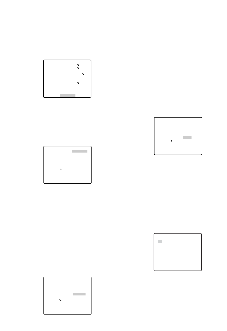
-49-
●Special 2 Menu (SPECIAL2)
This menu lets you adjust and set up the picture quality
to meet your requirements.
Move the cursor to SPECIAL2 and press the F3 button
of WV-CU650. The special menu appears on the moni-
tor screen. For WV-RM70, hold down the right and left
switches simultaneously for 2 seconds or more.
• Chroma Level (CHROMA GAIN)
Aperture Level (AP GAIN)
Pedestal Level (PEDESTAL)
Hue Level Setting (HUE)
1. Move the cursor to CHROMA GAIN, and the "I" cur-
sor is highlighted.
2. Move the "I" cursor to your desired position with the
joystick to confirm the level.
Notes:
•For setting the aperture, pedestal and hue levels,
perform the same steps described above (but in the
step 1, move the cursor to AP GAIN for the aperture
level, to PEDESTAL for the pedestal level.).
•To reset the settings to the factory default, press the
F3 button of WV-CU650. (For WV-RM70, hold down
the right and left switches simultaneously for 2 sec-
onds or more.)
• Resolution (RESOLUTION)
Move the cursor to RESOLUTION and move the joystick
to select NORMAL or HIGH.
** SET UP **
CAMERA ID
ALC/MANUAL
SHUTTER
AGC
SENS UP
SYNC
WHITE BAL
MOTION DET
AF MODE
RET SPECIAL2
OFF
ALC
AUTO
ON(MID)
OFF
INT
ATW1
OFF
AUTO L
** SPECIAL2 **
CHROMA GAIN – +
AP GAIN – +
PEDESTAL – +
HUE –••••
|
••••+
RESOLUTION
DNR LOW2
PIX OFF
REFRESH
CAMERA RESET
RET
••••
|
••••
••••
|
••••
•
|
•••••••
NORMAL
→
PUSH SET
→
PUSH SET
••••
|
••••
••••
|
••••
•
|
•••••••
NORMAL
→
PUSH SET
→
PUSH SET
** SPECIAL2 **
CHROMA GAIN – +
AP GAIN – +
PEDESTAL – +
HUE –••••
|
••••+
RESOLUTION
DNR LOW2
PIX OFF
REFRESH
CAMERA RESET
RET
NORMAL: Sets the horizontal resolution to more
than 480 lines.
HIGH: Sets the horizontal resolution to more than
510 lines.
Note:
After selecting HIGH, noise may increase when
the SENS UP function is activated under low illu-
mination.
• Digital Noise Reduction (DNR)
DNR may be used to improve quality under low light
conditions. There are 4 levels of DNR, which may be
selected depending on local site conditions. Factory
default setting: LOW2
You may need to try different settings to find the most
suitable conditions for your application.
Move the cursor to DNR and select LOW1, LOW2,
HIGH1 or HIGH2 with the joystick.
LOW1: DNR level is low. The after-image remains.
LOW2: DNR level is low. The after-image is
reduced.
HIGH1: DNR level is high. The after-image remains.
HIGH2: DNR level is high. The after-image is
reduced.
• PIX OFF Setting (PIX OFF)
In this setting, you can assign a blemish position and
compensate the blemish.
1. Move the cursor to PIX OFF and press the CAM
(SET) button. The PIX OFF menu appears.
2. Select a number and press the CAM (SET) button.
The blemish compensation position setting screen
appears.
Move the joystick to place the "+" cursor on the
blemish position. After moving the "+" cursor to a
position where the blemish looks inconspicuous,
press the CAM (SET) button. Consequently, the
blemish compensation position is set up and the PIX
OFF menu is restored.
••••
|
••••
••••
|
••••
•
|
•••••••
NORMAL
→
PUSH SET
→
PUSH SET
** SPECIAL2 **
CHROMA GAIN – +
AP GAIN – +
PEDESTAL – +
HUE –••••
|
••••+
RESOLUTION
DNR LOW2
PIX OFF
REFRESH
CAMERA RESET
RET
** PIX OFF **
1* 2* 3* 4*
5* 6* 7* 8
000 000
RET
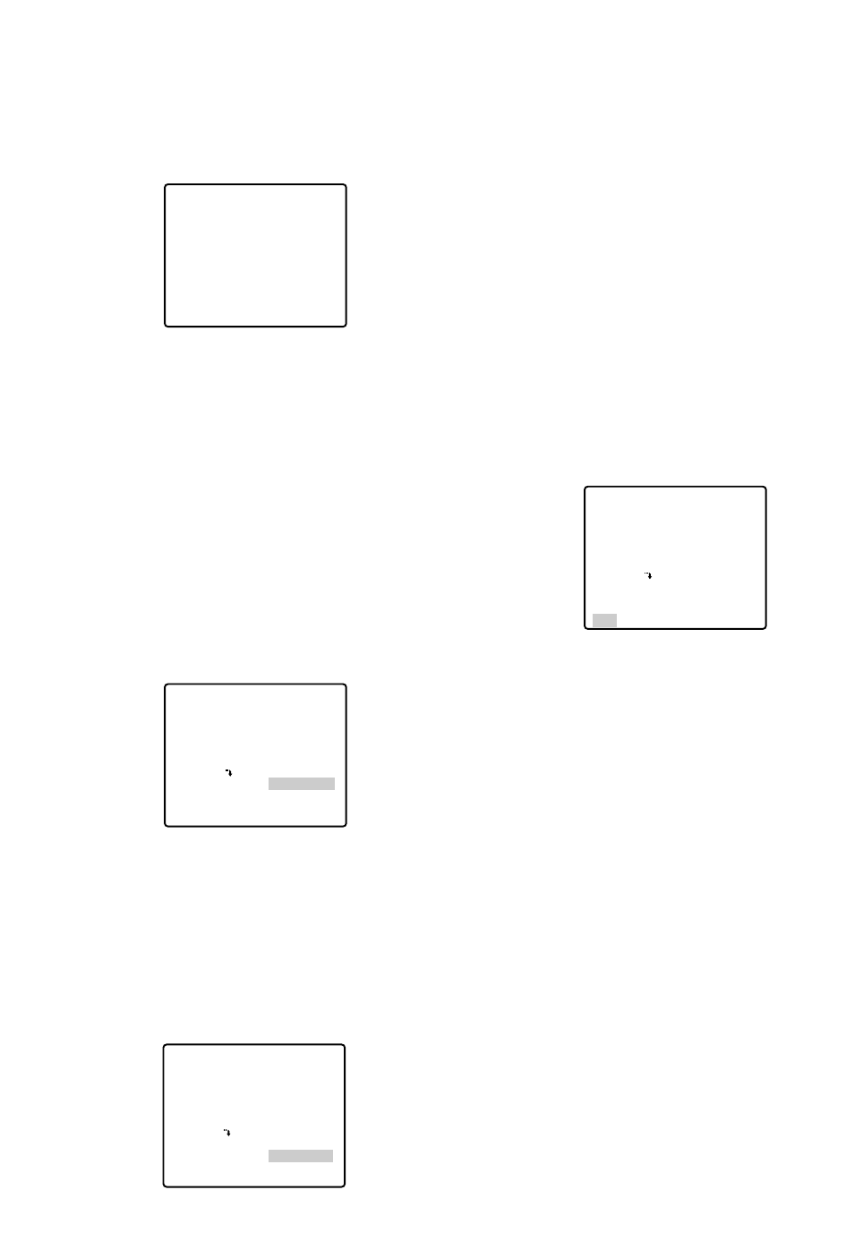
After a blemish compensation position is set up, (*)
is attached at the right of the number.
3. If you would like to delete a blemish compensation
position, move the cursor to the applicable number
and press the CAM (SET) button.
The blemish compensation position setting screen
appears. Press the F3 button of WV-CU650 when
the setting screen is active.
For WV-RM70, hold down the right and left buttons
simultaneously for 2 seconds or more.
For WV-CU161C, hold down the [4] and [6] keys
simultaneously for 2 seconds or more.
The screen is restored to the PIX OFF menu, the
blemish compensation position is deleted and (*) is
also deleted from the right of the number.
• To Restore the Camera Default Position
(REFRESH)
Move the cursor to REFRESH with the joystick and
press the F3 button of WV-CU650.
For WV-RM70, hold down the right and left buttons
simultaneously for 2 seconds or more.
For WV-CU161C, hold down the [4] and [6] keys simul-
taneously for 2 seconds or more.
• Camera Resetting (CAMERA RESET)
Move the cursor to CAMERA RESET with the joystick
and press the F4 button of WV-CU650.
-50-
The camera is reset to the factory default settings.
(However, the edited settings for PRESET MENU, AUTO
PAN, PATROL (SPECIAL 1), PIX OFF (SPECIAL 2) and
the registered password will not be reset.)
For WV-RM70, hold down the right, left and set switches
simultaneously for 2 seconds or more. For WV-CU161C,
hold down the [4], [5] and [6] keys simultaneously for 2
seconds or more.
The ALL RESET indication will be displayed.
Note:
In case of performing this operation on the condition
that the cursor is positioned on other than CAMERA
RESET, you cannot perform the operations on the
menu thereafter. In that event, set the camera menu
to ON again with the controller referring to page 26.
• To Close the SPECIAL2 Menu
Move the cursor to RET and press the CAM (SET) but-
ton.
The setup menu appears on the monitor screen.
Reset to the Factory Default Settings
Any of the above settings plus the ALC/MANUAL level
control and phase adjustments can be reset to the fac-
tory default settings by placing the cursor over the
desired mode and then pressing the F3 button of WV-
CU650.
For WV-RM70, hold down the right and left switches
simultaneously for 2 seconds or more.
For WV-CU161C, hold down the [4] and [6] keys simul-
taneously for 2 seconds or more.
** SPECIAL2 **
CHROMA GAIN – +
AP GAIN – +
PEDESTAL – +
HUE –••••
|
••••+
RESOLUTION
DNR LOW2
PIX OFF
REFRESH
CAMERA RESET
RET
••••
|
••••
••••
|
••••
•
|
•••••••
NORMAL
→
PUSH SET
→
PUSH SET
••••
|
••••
••••
|
••••
•
|
•••••••
NORMAL
→
PUSH SET
→
PUSH SET
** SPECIAL2 **
CHROMA GAIN – +
AP GAIN – +
PEDESTAL – +
HUE –••••
|
••••+
RESOLUTION
DNR LOW2
PIX OFF
REFRESH
CAMERA RESET
RET
••••
|
••••
••••
|
••••
•
|
•••••••
NORMAL
→
PUSH SET
→
PUSH SET
** SPECIAL2 **
CHROMA GAIN – +
AP GAIN – +
PEDESTAL – +
HUE –••••
|
••••+
RESOLUTION
DNR LOW2
PIX OFF
REFRESH
CAMERA RESET
RET
+

-51-
Menu
TOP MENU
SPECIAL 1
CAMERA MENU
SPECIAL 2
HOME POSITION
SELF RETURN
AUTO MODE
AUTO PAN KEY
DIGITAL FLIP
PASSWORD LOCK
PRIVACY ZONE
PROPO.P/T
AREA TITLE
PATROL
CLEANING
EL-ZOOM
PRESET ALM
IMAGE HOLD
TILT ANGLE
CAMERA ID
ALC/MANUAL
BLC
SHUTTER
AGC
SENS UP
SYNC
WHITE BAL
MOTION DET
AF MODE
CHROMA GAIN
AP GAIN
PEDESTAL
RESOLUTION
DNR
OFF
OFF
OFF
AUTO PAN
ON
OFF
OFF
ON
OFF
STOP
OFF
ON
OFF
OFF
0°
OFF
ALC
OFF
AUTO
ON (MID)
OFF
INT
ATW1
OFF
AUTO L
••••I••••
••••I••••
•••I•••••
HUE ••••I••••
NORMAL
LOW2
Item Setting Menu
PRESET MENU
AUTO PAN
SCENE FILE
RS485 SET UP
ALARM IN/OUT
PRESET ID
ALC/MANUAL
BLC
DWELL TIME
SCENE FILE
PRESET SPEED
SPEED
PAN LIMIT
ENDLESS
DWELL TIME
UNIT NUMBER
SUB ADDRESS
BAUD RATE
DATA BIT
PARITY CHECK
STOP BIT
XON/XOFF
WAIT TIME
ALARM DATA
DELAY TIME
ALARM IN1
ALARM IN2
ALARM IN3
ALARM IN4
CNT-CLS 1
TIME OUT
CNT-CLS 2
COAX ALM OUT
ON
ALC
OFF
10S
1
••••••••I
SHUTTER AUTO
AGC ON (MID)
SENS UP OFF
WHITE BAL ATW1
MOTION DET OFF
AF MODE MANUAL L
••••I••••
OFF
OFF
1S
1
1
19200
8
NONE
1
NOT USE
OFF
AUTO2
OFF
OFF
OFF
OFF
OFF
OFF
100MS
OFF
OFF
Item Setting
Factory Default Setting

Auto Focus
Zoom Ratio
Focus Speed
F1.6 - 22, CLOSE
Focal Length
BLC selectable ON/OFF (SETUP MENU)
x 22 +digital zoom x10
approx. 4.5 s (TELE/WIDE) in manual mode
approx. 5 s (FAR/NEAR) in manual mode
automatic (open/close is possible)/manual
1 : 1.6 (WIDE) - 3.0 (TELE)
3.79 - 83.4 mm
2.6° - 52.3°
2.0° - 39.9°
1/60 (OFF), AUTO, 1/100, 1/250, 1/500, 1/1 000, 1/2 000, 1/4 000, 1/10 000 s
Zoom Speed
Iris
Maximum Aperture Ratio
Angular Field
of View H
V
Electronic Shutter
Iris Range
MAX 32 times, AUTO/FIXSens Up ON (LOW)/ON (MID)/ON (HIGH)/OFFAGC
Cleaning
2 outputs (ALARM/AUX1, AUX2) open collector - output max. 16 V DC
100 mA OFF (OPEN)/ON (0 V)
Alarm OUT
4 inputs (ALARM IN 1 - 4) pulled up to 5.0 V DC OFF (open or 4 V DC - 5 V DC)/
ON (0 V 0.2 mA)
Alarm IN
Power Source
MANUAL/AUTO
OFF/SEQ/SORT/AUTO PAN/PATROL
SEQ/SORT/AUTO PAN/PATROL PLAY
ON/OFF
preset ID, camera ID, area title : up to 16 characters
ON/OFF
ON/OFF, up to 8 zones
ON/OFF
LEARN/PLAY/STOP, up to 60 seconds
ON/OFF
Image Hold ON/OFF
Auto Mode
Auto Pan Key
Digital Flip
Camera ID
Motion Detector
Privacy Zone
Proportional PAN/TILT
Patrol
Dimensions
24 V AC, 60 Hz
120 (D) x 191 (H) mm
(4-3/4" (D) x 7-1/2" (H))
approx. 2 kg(4.4 lbs)
–10°C - +50°C (14°F - 122°F)
(Recommended operating temperature: +35°C (95°F) or less)
13 WPower Consumption
Ambient Operating
Temperature
Weight
-52-
Effective Pixels
SPECIFICATIONS
Horizontal Scanning
Frequency
3.65 mm (H) x 2.74 mm (V), 1/4 in.
768 (H) x 494 (V) WV-CS574
15.734 kHz
internal/line-lock / multiplexed vertical drive (VD2)
59.94 Hz
1.0 V[P-P] NTSC composite/75 Ω
more than 480 lines at center (C/L, NORMAL), more than 510 lines at center
(C/L, HIGH)
more than 350 lines at center
50 dB (AGC OFF, weight on)
1 lx (0.1 foot-candle) C/L at SENS UP OFF (AGC HIGH)
Scanning Area
Synchronization
Vertical Scanning
Frequency
Video Output
Horizontal Resolution
Vertical Resolution
Signal-to-Noise Ratio
Minimum Illumination

-53-
Controls
Panning Range
Weights and dimensions indicated are approximate.
Specifications are subject to change without notice.
360° endless
possible (in auto-pan mode)
manual/sequential position/sort position/auto pan
manual : approx. 0.1°/s - 120°/s 8-steps/16-steps/64-steps
sequence position : maximum approx. 300°/s
0°to 180° (–5° to 185° at 5° tilt angle setting)
manual/sequential position/sort position
manual : approx. 0.1°/s - 120°/s. 8-steps/16-steps/64-steps
sequential position : maximum approx. 300°/s
pan/tilt, lens, 32 preset positions, home position
Panning Angle Setting
Panning Mode
Panning Speed
Tilting Range
Tilting Mode
Tilting Speed

-54-
SHORTCUTS
Shortcuts are supported when you are using the system controller that has a CAM FUNCTION button. With shortcuts,
you can configure camera functions by inputting function codes on the 10-key pad and then pressing the CAM
FUNCTION button.
The following is a list of all of the shortcuts that are supported by this camera. In addition, you can also move the cam-
era to a preset position by inputting the applicable position number on the 10-key pad.
Notes:
•Turn off digital flip before registering preset positions. If NO REGS.; FLIP ON appears, do the setting again.
•Shortcuts may not be performed if they are executed while a pan, tilt, zoom, or focus operation is in progress.
•Shortcuts 1 through 32, 169, 170 can be saved as part of a patrol routine.
•Except for shortcuts 169 and 170, executing any shortcut during patrol routine PLAY will cause the PLAY operation
to stop.
Controller Operation Setting
[6] + [5] + [CAM FUNCTION] AUTO PAN ON
[6] + [6] + [CAM FUNCTION] AUTO PAN OFF
[6] + [7] + [CAM FUNCTION] Increases AUTO PAN speed one step.
[6] + [8] + [CAM FUNCTION] Decreases AUTO PAN speed one step.
[6] + [9] + [CAM FUNCTION] Sets AUTO PAN start point.
[7] + [0] + [CAM FUNCTION] Sets AUTO PAN end point.
[7] + [1] + [CAM FUNCTION] AUTO MODE: OFF
[7] + [2] + [CAM FUNCTION] AUTO MODE: SEQ ON
[7] + [3] + [CAM FUNCTION] AUTO MODE: SORT ON
[7] + [4] + [CAM FUNCTION] Reverses AUTO PAN range.
[7] + [6] + [CAM FUNCTION] ENDLESS: ON
[7] + [7] + [CAM FUNCTION] ENDLESS: OFF
[7] + [8] + [CAM FUNCTION] DIGITAL FLIP: ON
[7] + [9] + [CAM FUNCTION] DIGITAL FLIP: OFF
[8] + [0] + [CAM FUNCTION] PROPO.P/T: ON
[8] + [1] + [CAM FUNCTION] PROPO.P/T: OFF
[8] + [4] + [CAM FUNCTION] BLC: ON
[8] + [5] + [CAM FUNCTION] BLC: OFF
[8] + [6] + [CAM FUNCTION] AF MODE: AUTO
[8] + [7] + [CAM FUNCTION] AF MODE: MANUAL
[8] + [8] + [CAM FUNCTION] Performs auto focus.
[8] + [9] + [CAM FUNCTION] Moves to home position.
[9] + [3] + [CAM FUNCTION] CAMERA ID: ON
[9] + [4] + [CAM FUNCTION] CAMERA ID: OFF
[9] + [5] + [CAM FUNCTION] AREA TITLE: ON (NESW)
[9] + [6] + [CAM FUNCTION] AREA TITLE: ON (USER)
[9] + [7] + [CAM FUNCTION] AREA TITLE: OFF
[1] + [0] + [0] + [CAM FUNCTION] Adjusts camera position (REFRESH)
[1] + [0] + [1] + [CAM FUNCTION] Stores preset to first available preset number (1 to 32).
[1] + [3] + [2] + [CAM FUNCTION]
[1] + [6] + [5] + [CAM FUNCTION] PATROL: PLAY
[1] + [6] + [6] + [CAM FUNCTION] PATROL: STOP
[1] + [6] + [7] + [CAM FUNCTION] PATROL: LEARN start
[1] + [6] + [9] + [CAM FUNCTION] IRIS: OPEN

-55-
Controller Operation Setting
[1] + [7] + [0] + [CAM FUNCTION] IRIS: CLOSE
[1] + [7] + [1] + [CAM FUNCTION] SHUTTER: ON
[1] + [7] + [2] + [CAM FUNCTION] SHUTTER: OFF
[1] + [7] + [3] + [CAM FUNCTION] Increases shutter speed one step.
[1] + [7] + [4] + [CAM FUNCTION] Decreases shutter speed one step.
[1] + [7] + [5] + [CAM FUNCTION] AGC: ON
[1] + [7] + [6] + [CAM FUNCTION] AGC: OFF
[1] + [7] + [7] + [CAM FUNCTION] SENS UP: FIX ON
[1] + [7] + [8] + [CAM FUNCTION] SENS UP: FIX OFF
[1] + [7] + [9] + [CAM FUNCTION] Increases electronic sensitivity enhancement (FIX) one step.
[1] + [8] + [0] + [CAM FUNCTION] Decreases electronic sensitivity enhancement (FIX) one step.
[1] + [8] + [1] + [CAM FUNCTION] SENS UP: AUTO ON
[1] + [8] + [2] + [CAM FUNCTION] SENS UP: AUTO OFF
[1] + [8] + [3] + [CAM FUNCTION] Increases electronic sensitivity enhancement (AUTO) one step.
[1] + [8] + [4] + [CAM FUNCTION] Decreases electronic sensitivity enhancement (AUTO) one step.
[1] + [8] + [5] + [CAM FUNCTION] Increases line lock phase (FINE) one step.
[1] + [8] + [6] + [CAM FUNCTION] Decreases line lock phase (FINE) one step.
[1] + [8] + [7] + [CAM FUNCTION] Pans 180°.
[1] + [8] + [8] + [CAM FUNCTION] CLEANING: ON
[1] + [8] + [9] + [CAM FUNCTION] CLEANING: OFF
*Do not do this operation with the previous dome type camera models (WV-CS850 series, WV-CS854, WV-CS854E
series, WV-CW860 series, WV-CW864, WV-CW864E series, and WV-CS564), doing so may cause a malfunction.
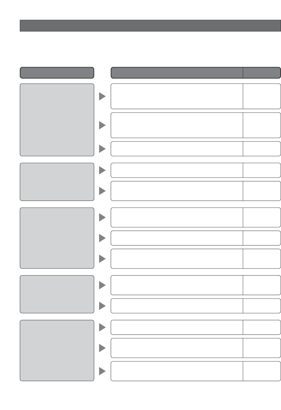
-56-
TROUBLESHOOTING
Before requesting service, check the following symptoms to see if you can solve the problem yourself.
If the countermeasures described below do not correct the problem, or if the symptoms you are experiencing are not
covered here, contact a quality service person or system installer.
Reference Pages
Cause and Recommended Action
Problem
No picture (dark screen)
White picture
Out of focus picture
Digital noise in the picture
Poor picture color
•Is the camera connected correctly? Check the oper-
ating instructions that come with your system con-
troller.
•Is the lens iris open?
•Is the dome cover or lens of the camera dirty? If so,
clean them.
•The slip ring may be dirty. Do you have the cleaning
function turned on?
•Check the white balance setting.
•Is FIX selected for the electronic sensitivity
enhancement (SENS UP) setting?
•Is the lens iris closed?
Execute the iris reset from the system controller you
are using.
•Is the camera set up for a fixed shutter speed?
–
29-30
6
41
46-47
•Use the special setup menu to adjust picture quali-
ty. 49
•Is the dome cover or lens of the camera dirty? If so,
clean them. 6
•Is the camera set up correctly? 42
•Is MANUAL selected for the auto focus mode? 48
•Is the object one that is not compatible with auto
focus? For such objects, focus manually. 48
30, 45
29-30
30, 44
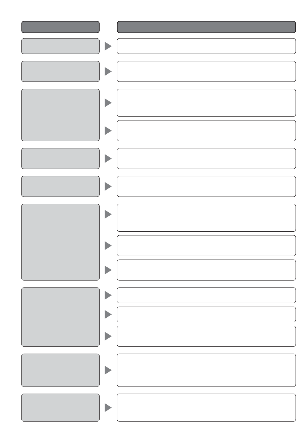
-57-
Afterimages in the picture
White specks in the picture
Menu does not open.
Menu settings will not
change.
I forgot the password.
•Check the DNR setting.
•Use the PIX OFF function to perform blemish com-
pensation.
•Is the camera connected correctly? See the operat-
ing instructions that come with the system controller
you are using.
•Is the password lock function turned on?
49
49
–
34
•Are camera communication settings configured cor-
rectly? 11-13
18-19
•Contact a quality service person or system installer. –
Pan, tilt, zoom, or focus do
not work.
The camera movement
modes (OFF, SEQ, SORT,
AUTO PAN, PATROL) do not
work.
The camera movement mode
(OFF, SEQ, SORT, AUTO
PAN, PATROL) setting
changes.
Camera position is different
from the preset position set-
ting.
•Is the camera connected correctly? See the operat-
ing instructions that come with the system controller
you are using. –
•The camera has a pan limit function. Check the PAN
LIMIT settings. 33
•The motor or lens may be worn. Contact a quality
service person or system installer. –
•Check the self return function. 31
•Check the ALARM IN settings. 40
•Check the recover time setting of the motion detec-
tor. 30
•Check the self return function. 31
•Perform REFRESH from the special setup menu. 50
Reference Pages
Cause and Recommended Action
Problem
-58-
Picture is different from the
position setting.
Upper part of the picture is
black when the camera is in
a horizontal orientation.
Reference Pages
Cause and Recommended Action
Problem
•Adjust the picture using the preset menu and a
scene file.
•This is caused by the camera's internal cover. It
does not indicate malfunction.
30
_
Camera suddenly starts to
pan by itself.
•If the cleaning function is turned on, this is normal
does not indicate malfunction. Check the CLEAN-
ING settings.
•If the cleaning function is not turned on, this symp-
tom could be due to noise.
41
Power cord sheathing is
damaged.
Power cord, connectors, or
power plug becomes hot
during operation.
Power cord becomes warm
or hot when it is bent or
stretched during use.
•The power cord, connector, or power plug is damaged. Continued
use creates the risk of electric shock and fire. Immediately unplug the
power plug and contact a qualified service person or system installer
for servicing.
●Periodically check the power cord and plug.
Reference Pages
Cause and Recommended Action
Problem
Panasonic Canada Inc.
5770 Ambler Drive,Mississauga,
Ontario, L4W 2T3 Canada (905)624-5010
http://www.panasonic.ca
Panasonic Sales Company
Division of Panasonic Puerto Rico Inc.
San Gabriel Industrial Park 65th Infantry Ave. KM. 9.5 Carolina
P.R. 00985(809)750-4300
Panasonic System Solutions Company,
Unit Company of Panasonic Corporation of North America
Security Systems
www.panasonic.com/security
For customer support, call 1.877.733.3689
Executive Office: Three Panasonic Way 2H-2, Secaucus, New Jersey 07094
Zone Office
Eastern: Three Panasonic Way, Secaucus, New Jersey 07094
Central: 1707 N. Randal Road, Elgin, IL 60123
Southern: 1225 Northbrook Parkway, Suwanee, GA 30024
Western: 6550 Katella Ave., Cypress, CA 90630
Printed in Japan
© 2005 Matsushita Electric Industrial Co., Ltd. All Rights Reserved. N0305-1055 3TR003479BAA Imprimé au Japon
