Pantech HWT-2150 WLL Terminal ( CDMA ) User Manual
Pantech Co., Ltd. WLL Terminal ( CDMA )
UserManual.wiki
>
Pantech
>
HWT-2150 User Manual
>
User manual
Contents
1.
User manual
2.
CRN 9389 Q1 revised user manual
3.
CRN 11551 Page 41 of user manual
User manual
Navigation menu
Upload a User Manual
Namespaces
Wiki Guide
HTML
PDF
Info
Views
User Manual
Discussion / Help
Navigation
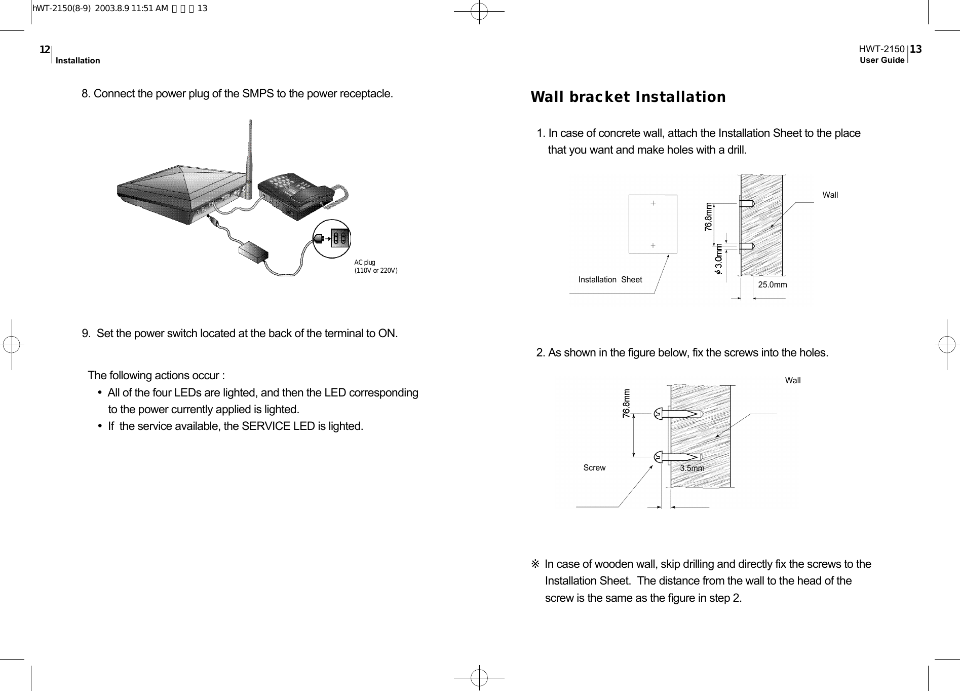
![Call Re c e i ve- When the Normal Phone is On-hook State①Pick up the handset when the normal phone rings.②Speak to the called party when the line is connected.③Hang up the handset after conversation.- When the Normal Phone is Off-hook State①Click the hook switch(hook-flash) if the normal phone receives thering signal (Call receive in off-hook is allowed only if the dial tone& warning tone are being sent and the bell rings through theb u z z e r ) .②Speak to the called party when the line is connected.③Hang up the handset after conversationA n a l o g G3 Fax Serv i c eTo use the analog G3 fax service from the terminal equipped with theanalog G3 fax board, you have to send/receive documentsaccording to the following procedure:- Sending DocumentsPress [✽00] and then press the number of destination. The otherprocedure is the same as that for general faxes.- Receiving DocumentsTo receive documents from the analog G3 fax, set the terminal to theAnalog G3 fax receive mode first. Pick up the handset of the fax andpress [✽✽✽✽1 5 ✽]. The fax is set to the Analog G3 fax receivemode(Set to Analog G3 fax receive mode until power off ) .You can not receive voices unless you reset the Analog G3 faxreceive mode. To reset the Analog G3 fax receive mode, pick up theHWT-2150User Guide 1 9Operation1 8handset of the fax and press [✽✽✽✽1 0 ✽]D ata Serv i c eWhen a PC is connected to the WLL terminal, the data service canprovide Internet and PC communication and fax send/receive. Aswireless data communication service may not be provideddepending on service providers, please check if the service providerprovides this service. This service is available after purchasing datacommunication cable from the service provider.For computer environment setup and other details, refer to the UserManual provided when you purchase the data communication cable.- Data Service Receive Mode Setting•Setting with a normal phoneThis function is used to set the receive mode according to dataservice type, using the normal phone connected to the W L Lt e r m i n a l①Pick up the handset of the normal phone and press [✽✽✽✽1 0✽] to reset the data service receive mode.②Pick up the handset of the normal phone and press [✽✽✽✽11✽] to set fax receive mode(one time).The fax receive mode is released automatically 10 minutes after s e t t i n g .③Pick up the handset of the normal phone and press[✽✽✽✽1 2✽] to set fax receive mode(Set to fax receive mode until power off ) .④Pick up the handset of the normal phone and press[✽✽✽✽1 3✽] to set modem receive mode(one time).The modem receive mode is released automatically 10 minutesafter setting.⑤Pick up the handset of the normal phone and press [✽✽✽✽1 4✽] to set modem receive modehWT-2150(8-9) 2003.8.9 11:51 AM 페이지19](https://usermanual.wiki/Pantech/HWT-2150.User-manual/User-Guide-348431-Page-10.png)
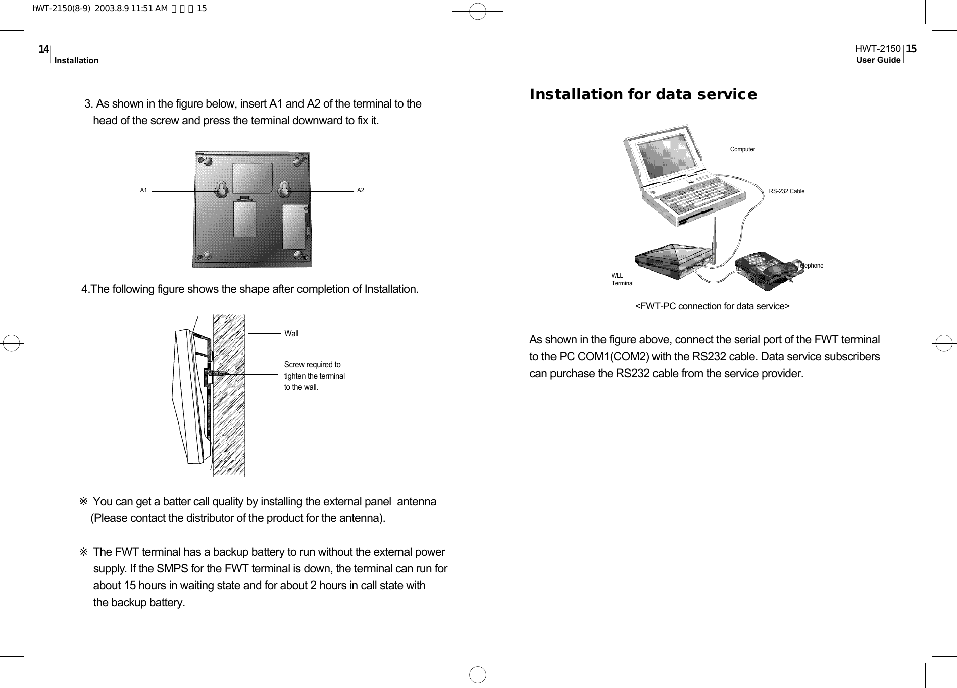
![(Set to modem receive mode until power off ) .⑥Default setting is [✽✽✽✽1 0✽] .•Setting with AT commandsThis function is used to set the receiving mode according to dataservice type,using the communication emulator program of PCconnected to the WLL terminal.①Enter [AT +Q CVAD=0] in the communication emulator programand press the Enter key.・After the setting is completed, OK is indicated and the data servicereceive mode is released. ②Enter [AT +Q CVAD=1] in the communication emulator programand press the Enter key. ・After the setting is completed, OK is indicated and the fax receivemode (one time) is set. The fax receive mode is releasedautomatically 10 minutes after setting.③Enter [AT +Q CVAD=2] in the communication emulator programand press the Enter key.・After the setting is completed, OK is indicated and the fax receivemode is set (Set to fax receive mode until power off ) .④Enter [AT +Q CVAD=3] in the communication emulator programand press the Enter key.・After the setting is completed, OK is indicated and the modemreceive mode is set (one time). The modem receive mode isreleased automatically 10 minutes after setting.⑤Enter [AT +Q CVAD=4] in the communication emulator programand press the Enter key.After the setting is completed, OK is indicated and the modemreceive mode is set (Set to modem receive mode until power off ) .⑥Default setting is [AT +Q CVA D = 0 ] .HWT-2150User Guide 2 1Operation2 0Supplement ServiceSpeed dial This function is used to save frequently used phone numbers inadvance and make a phone call quickly with the abbreviated code.You can save up to 99 phone numbers. Default setting is off .- Save phone numberEnter [##3233→1→1], enter a two-digit numbers(01~99) for theaddress to save the phone number and press the [✽] button(save).# # 3 2 3 3→1→1→address(2 digits)→phone numbers→✽: save phone numbers- Delete phone numberEnter [##3233→1→2], enter the address(01~99) to delete and press[✽] button. To delete all phone numbers saved, enter [##3233→1→3] and press the [✽] button.##3233 →1 →2 →address(2 digits) → ✽ : delete one address##3233 →1 →3 →✽ : delete all address- Speed dial on and offEnter [##3233→1→4] and then press the [✽] button(on). The speeddial mode is enabled only if the speed dial function is on althoughphone numbers are saved in the memory.To disable the function(off), enter [##3233→1→5] and then pressthe [✽] button.hWT-2150(8-9) 2003.8.9 11:51 AM 페이지21](https://usermanual.wiki/Pantech/HWT-2150.User-manual/User-Guide-348431-Page-11.png)
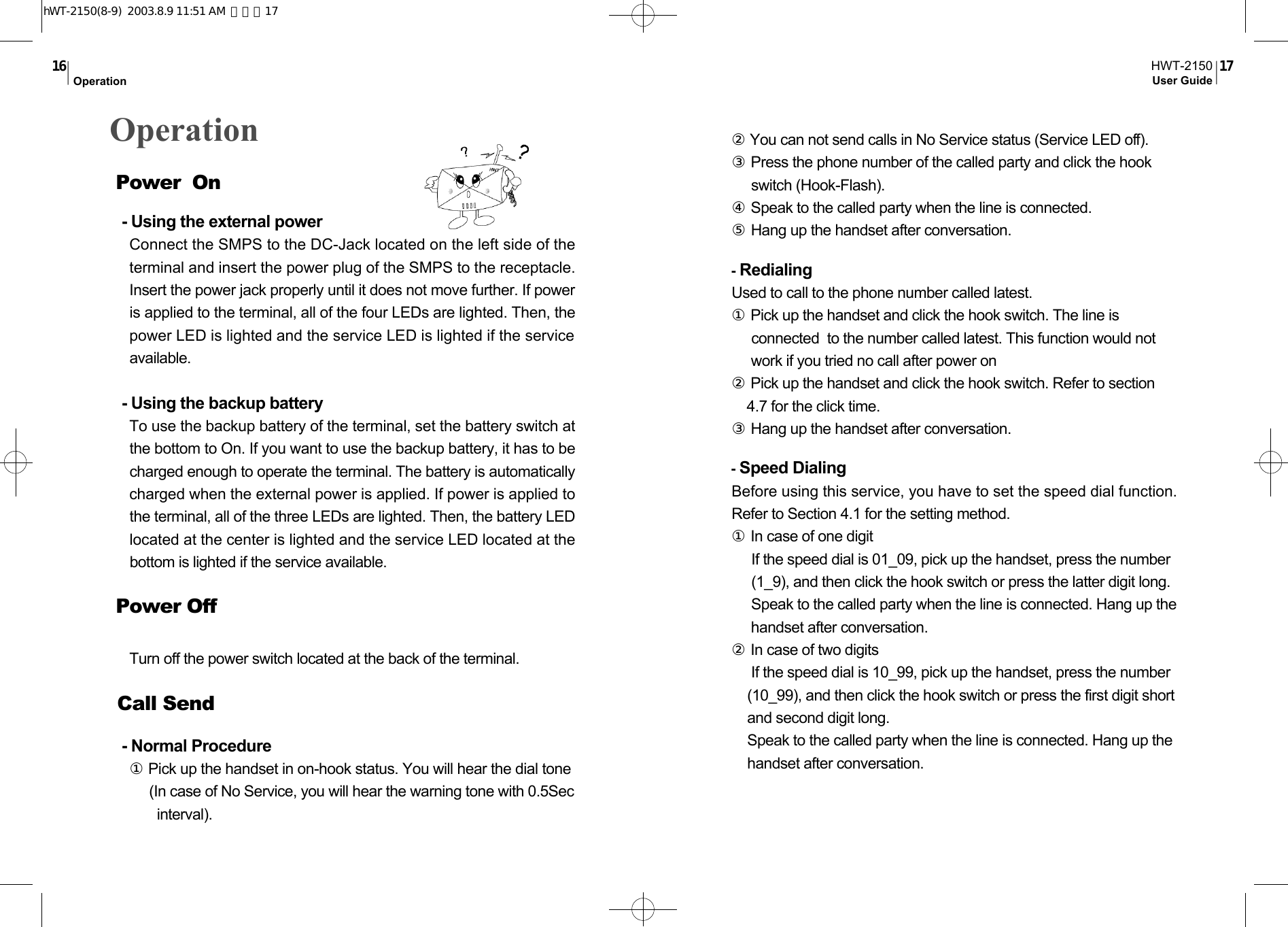
![HWT-2150User Guide 2 3Supplement Service2 2##3233 →1 →4 → ✽ : speed dial on##3233 →1 →5 → ✽ : speed dial off- Speed DialingIf the phone number is saved in the address and the speed dial functionis enabled(on), you can make a phone call by entering just the address.If the saved address is one digit(01~09), press the latter digit long orpress it short and click the hook switch to make a phone call to thesaved number.If the saved address is two digits(10~99), press the first digit short andthe second digit long or press the two digits short and click the hookswitch to make a phone call to the saved number.If you attempt a call while the speed dial function is off, you will hear thereject tone and fail to make a phone call.E m e rge n c y call hold This function is used to register up to three phone numbers(Address01~03) in advance to prepare for emergencies and quickly make aphone call with the speed dial. The line connected is held on as long asthe called party does not release. Default setting is off .- Emergency call hold on and offEnter [##3233 →1 →6] and press [✽] button(on). The emergency callhold function is activated when phone numbers are saved in address01~03 and the emergency call is on. You can save phone numbers inaddress 01~03 in the same way as "4.1.1" .To deactivate the emergency call hold function(off), enter [##3233 →1 →7] and press the [✽] button.Reference: Warning Tone/Howler(ROH:Receiver Off-Hook) ToneIf you pick up the handset (Off-Hook) and do not press buttons for the given time, thedial tone changes to the warning tone. At this time, you can receive calls but can notsend calls as number input is not allowed. In this case, you have to put back the handset(On-Hook) and pick it up again (Off-Hook) to attempt a call. If you hold the handsetafter the dial tone has changed to the warning tone, the warning tone changes to theHowler (ROH) Tone after the given time. You can hear the Howler Tone through thebuzzer. From that time on, you can not send or receive calls until you hang up (On-Hook) the handset. ##3233 →1 →6 →✽ : emergency call hold on##3233 →1 →7 →✽ : emergency call hold off- Emergency callWhen phone numbers are stored in address 01~03 and theemergency call is on, if you press the latter digits of the address longor two digits short and click the hook switch, the call is connected tothe stored number and is held on as long as the called party does notr e l e a s e .If you attempt speed dialing when emergency call hold and speed dialare enabled concurrently, the address 01~03 are operated inemergency call hold mode.If you attempt speed dialing when emergency call hold is off andspeed dial is on, the address 01~03 are operated in speed dial mode.Reference: Confirmation Tone/Reject ToneIf you press the [✽] button(save) after all key operation for supplementary servicesetting is normally accomplished, the telephone returns to the initial status after hook-off and the Confirmation Tone is sent to notify that the setting has been accomplishednormally. If an incorrect key is entered, a short reject tone is sent to notify the error.Then, you can continue the operation from that step.hWT-2150(8-9) 2003.8.9 11:51 AM 페이지23](https://usermanual.wiki/Pantech/HWT-2150.User-manual/User-Guide-348431-Page-12.png)
![HWT-2150User Guide 2 5Supplement Service2 4Hot Line Serv i c eThis function is used to register one frequently used number(address 99) in advance and automatically make a phone call tothe number after hook-off. Default setting is Off .Hot line is operated in 2 modes; timed hot line mode to connectthe line after the specified time (4sec~8sec) and immediate hotline mode to connect the line just after off - h o o k .- Hot line on and offEnter [##3233→1→8→1].and press the [✽] button to set timedhot line(On). If a phone number is saved in addess 99 and the hot line function is set to timed hot line mode, the line is connected the dial sendtime (4sec~8sec) after hook-off .Also, enter [##3233→1→8→2].and press the [✽] button to set immediate hot line(On).If a phone number is saved in address 99 and the hot line functionis set to immediate hot line mode, the line is connected just afterhook- off. ##3233 →1 →8 →1 →✽ : Timed hot line on##3233 →1 →8 →2→✽ : Immediate hot line on##3233 →1 →8 →3→✽ : Hot line off- Hot line callingIf a phone number is saved in address 99 and the hot linefunction is set to timed hot line mode, the line is connected the dial send time(4sec~8sec) after hook-off. Also, if a phone number issaved in address 99 and the hot line function is set to immediate hotline mode, the line is connected just after hook-off .A l a rm reminder If you set a time in advance, the alarm rings on the specified timeand stops when you pick up the handset. Default setting is off .- Alarm reminder on and offEnter [##3233→2→1] and four digits for a desired time(24 hours) andpress the [✽] button(on). The alarm reminder function is automatically set to one time. Thealarm rings on the specified time and then the alarm reminder isreleased (off ) .If you want to activate the alarm at the same time everyday, enter[ # # 3 2 3 3→2→3→✽] to activate the alarm reminder and enter[ # # 3 2 3 3 →2→4→✽] to deactivate it.##3233 →2 →1 →Hour(4 digits, 24 hours) → ✽: Alarm time input and setting (one time)##3233 →2 →2 → ✽ : Alarm reminder on (one t i m e )##3233 →2 →3 →✽ : Alarm reminder on (always)##3233 →2 →4 → ✽ : Alarm reminder off R e f e r e n c e :When immediate hot line is on, you can not send calls to other numbers.To make a phone call to other number, enter the setup mode by pressing the [#] buttonwithin one second after hook-off and change the hot line mode.hWT-2150(8-9) 2003.8.9 11:51 AM 페이지25](https://usermanual.wiki/Pantech/HWT-2150.User-manual/User-Guide-348431-Page-13.png)
![HWT-2150User Guide 2 7Supplement Service2 6L o ckThis function is used to enter a password into the terminal to rejectcalls from users who are not aware of the password.If you attempt a call when the lock function is on, the warning tone isheard and the call is not connected (Call receive is allowed).H o w e v e r, if the emergency call function is on, origination ofemergency calls (address 01~03) is allowed. Default setting is off .- Lock on and offEnter [##3233→3] and a password of four digits. If you enter anincorrect password, you will hear the reject tone. If the correctpassword is entered, press [1] and then the [✽] button(lock on). Torelease the lock function, enter [##3233→3→p a s s w o r d→2→✽] .##3233 →3 →password →1 → ✽ : Locking on##3233 →3 →password →2 → ✽ : Locking off- Password changeTo change the password, press [##3233→3] and then enter thepassword. Press[3], enter a new password and press the [✽] b u t t o n .Enter the new password again and press the [✽] button to changethe password to the new one.##3233 →3 →password →3→new password →✽→new password→✽: change passwordR e f e r e n c e : The default password for lock is "0000".E a r -piece volume contro lUsed to control the volume of ear-piece. Default setting is Level3[#### 03].- Ear-piece volume control method①Enter [##3233 →4 →1], enter a desired button out of 1(level 1),2(level 2), 3(level 3), 4(level 4), 5(level 5), and then press the [✽]button to save."1" is the smallest volume. The bigger the number is, the largerthe volume is.# # 3 2 3 3→4→1→1 ~ 5 →✽: Ear-piece volume(Method 1)②Pick up the handset of the normal phone and press [####]. Entera desired number out of 01~05, and then press the [✽] button tosave. You will hear the dial tone after the volume control isc o m p l e t e d .#### →01~05 →✽: Ear-piece volume control (method 2)Reset Used to reset the terminal setup.- Reset method①Enter [##3233→4→0] and the lock code or the maintenancecode and then press [✽] button.##3233 →4 →0 →✽ : ResethWT-2150(8-9) 2003.8.9 11:51 AM 페이지27](https://usermanual.wiki/Pantech/HWT-2150.User-manual/User-Guide-348431-Page-14.png)
![HWT-2150User Guide 2 9Supplement Service2 8Reset items and their status are listed below:CLIP SettingAs the terminal type FWT has no display, the calling party’s numbercan be indicated by connecting a specific module or a display typetelephone. This function is used to set communication method of them o d u l e .- CLIP Setting Method①Enter [##3233 →5 →Maintenance Code →1 →1(DTMF mode) or 2 (FSK mode)] and press the [✽] button to save.##3233 →5 →Maintenance Code →1 →1 or 2→ ✽: CLIP setting I t e m s S t a t u sSpeed dialE m e r gency call holdHot line callA l a r mL o c kE a r -piece volumeo f fo f fo f fo f fo f flevel 3R e f e r e n c e : The Maintenance Code “2733” is used only for maintenance.A n a l o g G3 Fax Standard SettingThe terminal can provide fax service using two types of Analog G3Fax standards.This function is used to set the standard.- Analog G3 Fax Standard SettingAnalog G3 Fax service is provided using the IS-99/IS-707.4 basedPC Fax standard or the IS-707A.7 Analog G3 Fax standard. WhenIS-99/IS-707.4 based PC Fax standard is used, you have to selectthe default Fax receiving mode. ①IS-99/707.4 PC Fax settingEnter [##3233 →5 →Maintenance Code →2 →1], select “1” (PC fax) or “2” (Analog G3 Fax), and then press the [✽] button to s a v e .##3233 →5 →Maintenance Code →2 →1 →1 or 2 →✽: IS-99/707.4 PC Fax based mode settingR e f e r e n c e : Default receiving mode is system-dependent (Unnecessary depending onsystem configuration.). If the system is configured with single DN, the default receivingmode is not applied as Fax receiving depends on user’s receive mode setting (Datareceiving through the analog G3 Fax in case of ****15* and through the PC in case of****12*). Also, if the system is configured with two DNs (if fax calls are receivedaccording to the service option determined by the system), the terminal receives callsaccording to the default receiving mode setting.hWT-2150(8-9) 2003.8.9 11:51 AM 페이지29](https://usermanual.wiki/Pantech/HWT-2150.User-manual/User-Guide-348431-Page-15.png)
![HWT-2150User Guide3 1Supplement Service3 0②IS-707A.7 Analog G3 Fax standard setting.Enter [##3233 →5 →Maintenance Code →2 →2] and press the [✽]button to save.##3233 →5 →Maintenance Code →2 →2 →✽: IS-707A.7 Analog G3 Fax standard settingD e fault Data Rate SettingThe terminal supports two types of data rates according to thes t a n d a r d s .This function is used to set the default rate for data calls.- Default Data Rate Setting ①Setting IS-99 Rate Set 1 : Enter [##3233 →5 →Maintenance Code →3], select “1”, and then press the [✽] button to save.##3233 →5 →Maintenance Code →3 →1 →✽: Setting default data rate (8K) to RS1 (IS99)②Setting IS-99 Rate Set 2: Enter [##3233 →5 →Maintenance Code →3], select “2”, and then press the [✽] button to save.##3233 →5 →Maintenance Code →3 →2 → ✽: Setting default data rate to RS2 (IS-99 based)③Setting IS-707.4 Rate Set 1 : Enter [##3233 →5 →Maintenance Code →3], select “3”, and then press the [✽] button to save.##3233 →5 →Maintenance Code →3 →3 →✽: Setting default data rate to RS1(IS-707.4 based)④Setting IS-707.4 Rate Set 2 : Enter [##3233 →5 →Maintenance Code →4], select “4”, and then press the [✽] button to save.##3233 →5 →Maintenance Code →3 →4 →✽: Setting default data rate to RS2(IS-707.4 based)R i n ger Fre q u e n c y & Cadence Control This function is used to control the ringer frequency and cadence.Select the frequency first and then select the cadence. Defaultsetting is 20Hz, 1 sec On – 2sec Off .- Ringer Frequency SettingEnter [##3233 →5 →Maintenance Code →4]. Select a desired number from 1 (16Hz) , 2 (20Hz) and 3 (25Hz). - Ringer Cadence SettingAfter selecting the frequency, select the cadence. Select a desired number from 1~ 6 and press the * button to terminate ringer frequency and ringer cadence setting.No. 1: 1Sec On – 2 Sec OffNo. 2: 0.4 Sec On – 0.2 Sec Off - 0.4 Sec On – 2 Sec OffNo. 3: 1 Sec On – 4.5 Sec OffNo. 4: 1 Sec On – 4 Sec Off hWT-2150(8-9) 2003.8.9 11:51 AM 페이지31](https://usermanual.wiki/Pantech/HWT-2150.User-manual/User-Guide-348431-Page-16.png)
![HWT-2150User Guide3 3Supplement Service3 2No. 5: 0.25 Sec On – 0.25 Sec Off - 0.25 Sec On – 1.25 Sec OffNo. 6: 2 Sec On – 4 Sec Off##3233 →4 →3 →1~3(frequency) →1~6(cadence) →✽: Ringer frequency & cadence settingDial Tone Fre q u e n c y Control This function is used to select the dial sent from the handset. Defaultsetting is 350 + 440Hz dual tone.- Dial Tone Frequency Control Method①Enter [##3233 →5 →Maintenance Code →5 ] .Select a desired number from 1 (350+440Hz) , 2 (400Hz) , 3 (425Hz) and 4 (450Hz) and press the [✽] button.##3233 →5 →Maintenance Code →5 →1~4 → ✽: Dial Tone Frequency Control (Method 1)②Pick up the handset of the normal phone, press [####], and enter a desired number out of 51 (350+440Hz) , 52(400Hz) , 53(425Hz) and 54(450Hz).#### →51~54 : Dial Tone Frequency Control (Method 2)D e fault Vocoder SelectionThe terminal provides service with three Vocorder types.This function is used to select the Vocorder type.- Vocoder Selection MethodEnter [##3233 →5 →Maintenance Code →6], select one of “1” (8K EVRC) or “2” (13K QC E L P ) and then press the [✽] button to s a v e .##3233 →5 →Maintenance Code →6 →1 or 2 →✽: Vocoder selection Timed Hot Line Dial Send Waiting TimeC o n t ro lThis function is used to control the hot line number send time whenthe Timed Hot Line is On. The Hot Line number send time isadjustable from 4 sec to 8 sec and default setting is 6 sec.- Timed Hot Line Dial Send Waiting Time Setting①Enter [##3233 →5 →Maintenance Code →7 ] .Select a desired number from 4 , 5 , 6 , 7 and 8 and press the [✽] b u t t o n .For example, to set 7 sec, press 7 and the [✽] button. ##3233 →5 →Maintenance Code →7 →4~8 →✽: Timed Hot Line Dial send time setting (Method 1)hWT-2150(8-9) 2003.8.9 11:51 AM 페이지33](https://usermanual.wiki/Pantech/HWT-2150.User-manual/User-Guide-348431-Page-17.png)
![HWT-2150User Guide3 5Supplement Service3 4②Pick up the handset of the normal phone, press [####], and then select a desired number from 04~08. ‘04’ indicates automatic call send after 4 seconds and ‘08’ indicates automatic call send after eight seconds.#### →04~08 : Timed Hot Line Dial send time setting (Method 2)Hook Flash Time (Click Time) Control This function is used to set the time required to recognize click of thehook switch for redial and speed dial. Default setting is 100-700ms.- Hook Flash Time Control Method①Enter [##3233 →5 →Maintenance Code →8 →1], enter two digits (05~98) for the minimum time by the 10msec, and then press the [✽] button to save.##3233 →5 →Maintenance Code →8 →1 →05~98 → ✽: Hook Flash minimum time setting②Enter [##3233 →5 →Maintenance Code →8 →2], enter two digits (06~99) for the maximum time by the 10msec, and then press the [✽] button to save. ##3233 →5 →Maintenance Code →8 →2 →06~99 →✽: Hook Flash maximum time settingR e f e r e n c e : If the minimum time is set to 50 ~ 90 msec, it is not available for dial pulse type telephones.Voice Priva cy SettingThe terminal supports voice privacy.- Voice Privacy OnEnter [##3233 →5 →Maintenance Code →9 →1] and press the [✽] button to save. - Voice Privacy OffEnter [##3233 →5 →Maintenance Code →9 →2] and press the [✽] button to save.##3233 →5 →Maintenance Code →9 →1 or 2 →✽: Voice Privacy on/offSerial Interface Setting (None for HWP- 2 1 5 0 )The terminal supports data serve when it is connected to the PCthrough RS-232 serial interface. The HWT-2150 terminal providestwo data rates for PC interface. It provides 115200 bps for high-speed packet data service and 19200 bps for modem, PC Fax andlow speed packet data service.- Setting serial interface to 19200 bps①Enter [##3233 →5 →Maintenance Code →0, select “1”], and then press the [✽] button to save.##3233 →5 →Maintenance Code →0 →1 → ✽: Setting the serial data baudrate to 19200 bpshWT-2150(8-9) 2003.8.9 11:51 AM 페이지35](https://usermanual.wiki/Pantech/HWT-2150.User-manual/User-Guide-348431-Page-18.png)
![HWT-2150User Guide3 7Supplement Service3 6- Setting Serial Interface to 115200 bpsEnter [##3233 →5 →Maintenance Code →0, select “2”], and then press the [✽] button to save.##3233 →5 →Maintenance Code →0 →2 →✽: Setting the serial data baudrate to 115200 bpsA Key Value InputThe terminal supports OTASP service that requires authentication.This function is used to enter A key value required for theauthentication procedure.- A Key Input Enter [##3233 →6 →Maintenance Code →1], enter a number corresponding to the A Key value up to 26 digits, and then press the [✽]button to save.##3233 →6 →Maintenance Code →1 →A Key No.(26 digits) → ✽: A Key inputN e t wo rk Dial Tone SettingThe terminal provides the network dial tone depending onconfiguration of the system (system dependent). The terminalconnected to a system that provides the network dial tone provides“LE-Generated dial tone”. Other systems provide “NIU-generateddial tone”.- Network Dial Tone OffEnter [##3233 →6 →Maintenance Code →2, select “1”], and then press the [✽] button to save.##3233 →6 →Maintenance Code →2 →1 →✽: NIU-generated dial tone setting- Network Dial Tone On Enter [##3233 →6 →Maintenance Code →2, select “2”], and then press the [✽] button to save.##3233 →6 →Maintenance Code →2 →2 → ✽: LE-Generated dial tone settingSystem Pa rameter InputYou can enter/change channel number and MIN number of thesystem parameters with the handset.- Channel Number Input Enter ##3233 →9 →Maintenance Code →1~4, enter three digits of the channel number, and then press the [✽] button to save.1 : Primary System A channel 2 : Secondary System A channel3 : Primary System B channel 4 : Secondary System B channel##3233 →9 →Maintenance Code →1~4 →Channel No. → ✽: Channel number inputhWT-2150(8-9) 2003.8.9 11:51 AM 페이지37](https://usermanual.wiki/Pantech/HWT-2150.User-manual/User-Guide-348431-Page-19.png)
![HWT-2150User Guide3 9Supplement Service3 8- MIN Number InputEnter ##3233 →9 →Maintenance Code →5, enter up to ten digits for the MIN number, and then press the [✽] button to save.##3233 →9 →Maintenance Code →5 →MIN No. → ✽: MIN number inputA p p e n d i xS u m m a ry tabl eS a v e / d e l e t ephone numberSpeed dialingEmergency callh o l dHot lineAlarm reminderL o c kEar-piece volumeadjusting ( 5 steps)R e s e tClip settingAnalog G3 FaxStandard SettingDefault Rate Set Ringer Frequency & Cadence ControlDial Tone FrequencyC o n t r o lS a v eDelete one addressDelete all addressesO nO f fO nO f fTime hot line onImmediate hot lineO f fTime input(one time)One time modeAlways modeAlarm offO nO f fChange password# # # # →01/02/03/04/05 →✽# # 3 2 3 3 →4→1→1 ~ 5 →✽# # 3 2 3 3 →4→0→p a s s w o r d →✽##3233 →5 →Maintenance Code →1 →1 / 2 →✽( 1 : DTMF(BINA) Mode, 2 : FSK Bellcore Mode)IS-99/707.4 PC Fax ModeIS-707A.7 Mode##3233 →5 →Maintenance Code →3 →1 / 2 / 3 / 4 →✽(1 : RS 1 (IS99) , 2 : RS 2(IS99) , 3 : RS 1(IS707.4) , 2 : Rate Set 2 (IS707.4))##3233 →5 →Maintenance Code →4 →1 / 2 / 3 (frequency) →1 / 2 / 3 / 4 / 5 / 6 (cadence) →✽(Frequency 1: 16Hz 2: 20Hz 3: 25Hz / Cadence 1,2,3,4,5, 6 : Refer to 4.8.2)##3233 →5 →Maintenance Code →5 →1 / 2 / 3 / 4 →✽( 1: 350+440Hz 2: 400Hz 3: 425Hz 4: 450Hz )# # 3 2 3 3→1→1→a d d r e s s →phone number# # 3 2 3 3→1→2→a d d r e s s →✽# # 3 2 3 3→1→3→✽# # 3 2 3 3→1→4→✽# # 3 2 3 3→1→5→✽# # 3 2 3 3→1→6→✽# # 3 2 3 3→1→7→✽# # 3 2 3 3→1→8→1→✽# # 3 2 3 3→1→8→2→✽# # 3 2 3 3→1→8→3→✽# # 3 2 3 3→2→1→hour(4 digits, 24 hours) →# # 3 2 3 3→2→2→✽# # 3 2 3 3→2→3→✽# # 3 2 3 3→2→4→✽# # 3 2 3 3→3→p a s s w o r d →1→✽# # 3 2 3 3→3→p a s s w o r d →2→✽# # 3 2 3 3→3→p a s s w o r d →3→New p a s s w o r d →✽→new p a s s w o r d →✽##3233 →5 →Maintenance Code →2 →1 →1 / 2 →✽( 1 : PC Fax receiving default , 2 : Analog G3 receiving default )##3233 →5 →Maintenance Code →2 →2 →✽(01:Min ←03:Middle →0 5 : M a x )( 1 ~ 5 : s t e p 1 ~ s t e p 5 )✽hWT-2150(8-9) 2003.8.9 11:51 AM 페이지39](https://usermanual.wiki/Pantech/HWT-2150.User-manual/User-Guide-348431-Page-20.png)
![HWT-2150User Guide4 1Appendix40D e f a u l tVocoder S.O Timed Hot Line Dial Send Waiting TimHook FlashTime ControlVoice Privacy Serial InterfaceS e t t i n gA Key ValueI n p u tNetwork DialT o n eC h a n n e lNumber InputMIN NumberI n p u tAnalog G3 faxr e c e i v eData servicereceive mode releaseFax receive modesetting (one time)Fax receive modesetting(until power off)Modem receivemode (one time)Modem receivemode(until power off)##3233 →5 →Maintenance Code →6 →1/ 2 →✽( 1 : 8K EVRC , 2 : 13K QC E L P )##3233 →5 →Maintenance Code →7 →4 / 5 / 6 / 7 / 8 →✽( 4: 4 Sec 5: 5 Sec 6: 6 Sec 7: 7 Sec 8: 8 Sec )##3233 →5 →Maintenance Code →8 →1 (Min time) →05~98 →✽##3233 →5 →Maintenance Code →8 →2 (Max time) →06~99 →✽( 05 ~ 99 : 50 msec ~ 990 msec)O nO f f19200 bps115200 bps##3233 →6 →Maintenance Code →1 →“AKEY” (26 digits) →✽( AKEY : 26-digit A Key value)NIU-generated Dial ToneLE-generated Dial Tone# # 3 2 3 3→9→Maintenance Code→1(Primary A CH No.) →www (3digits)→✽( www : Primary System A Channel No.)# # 3 2 3 3→9→Maintenance Code→2(Secondary A CH No.)→xxx (3digits)→✽( xxx : Secondary System A Channel No.)# # 3 2 3 3→9→Maintenance Code→3(Primary B CH No.)→yyy (3digits) →✽( yyy : Primary System B Channel No.)# # 3 2 3 3→9→Maintenance Code→4(Secondary B CH No.)→zzz (3digits)→✽( zzz : Secondary System B Channel No.)# # 3 2 3 3→9→Maintenance Code→5→xxxxxxxxxx (10digits)→✽( xxxxxxxxxx : MIN No.)On (fax receive)Off (voice receive)Using the normal phoneUsing the emulatorUsing the normal phone Using the emulatorUsing the normal phone Using the emulatorUsing the normal phone Using the emulatorUsing the normal phone Using the emulator✽✽✽✽1 5✽✽✽✽✽1 0✽✽✽✽✽1 0✽[ A T +QCVAD=0] →Enter key✽✽✽✽1 1✽[ A T +QCVAD=1] →Enter key✽✽✽✽1 2✽[ A T +QCVAD=2] →Enter key✽✽✽✽1 3✽[ A T +Q C VAD=3] →Enter key✽✽✽✽1 4✽[ A T +Q C VAD=4] →Enter key##3233 →5 →Maintenance Code →9 →1 →✽##3233 →5 →Maintenance Code →9 →2 →✽##3233 →5 →Maintenance Code →0 →1 →✽##3233 →5 →Maintenance Code →0 →2 →✽##3233 →6 →Maintenance Code →1 →1 →✽##3233 →6 →Maintenance Code →1 →2 →✽Air InterfaceBattery Back-up Connectors for variousService supportP h y s i c a lE n v i r o n m e n t a lPower SupplyA c c e s s o r i e sCommon air interface standard →IS-2000FREQUENCY →TX : 824 – 849MHzRX : 869 – 894MHzTX Output Power →200mWRX Sensitivity →- 104dBmVocoder →8K/13K QCELP, 8K EVRCChannel Bandwidth →CDMA 1.25MhzSpurious →TX : -61dBm belowRX : -81dBm belowMOD/DEMOD →O QPSK/QPSKFrequency Accuracy →Fo°w300Hz Type →Ni-MHCapacity →3.6V @ 1.8ATalk Time →2 HoursStandby Time →20HoursRJ-11 →Standard wire-line telephoneAnalog G3 Fax (Optional) Serial port →Maintenance PurposeData Service Purpose ( Internet, PC Fax)Dimension(D xW xH) →180 x180 x57mmWeight ( including Backup battery) →546gOperating Temperature →-10°C ~ +50°CStorage Temperature →-20°C ~ +70°CInput Power →100 ~ 240Vw10%,48~62HzOutput Power →5.5V 1.2AInternal Antenna →Di-Pole AntennaPower supply External Antenna ( Optional ) →10dbi GainDirectional Panel AntennaTe chnical Specificat i o n- 800MHz hWT-2150(8-9) 2003.8.9 11:51 AM 페이지41](https://usermanual.wiki/Pantech/HWT-2150.User-manual/User-Guide-348431-Page-21.png)