Pantech HWT-2150 WLL Terminal ( CDMA ) User Manual
Pantech Co., Ltd. WLL Terminal ( CDMA )
Pantech >
Contents
User manual

Precautions in using ……………………………………… 5
Components Check ………………………………………… 6
Function Description of Each Component ……………… 7
General installation…………………………………………… 9
Wall bracket Installation ……………………………………13
Installation for Data Service ………………………………15
Power on ………………………………………………………16
Power off ………………………………………………………16
Call Send ………………………………………………………17
Call Receive ……………………………………………………17
Analog G3 fax service ……………………………………… 18
Data service …………………………………………………18
Contents
Speed Dial ………………………………………………… 21
Emergency call hold ……………………………………… 22
Hot Line Service …………………………………………… 24
Alarm Reminder …………………………………………… 25
Lock ………………………………………………………… 26
Ear-piece Volume Control ………………………………… 27
Reset ……………………………………………………… 27
Clip Setting ………………………………………………… 28
Analog G3 Fax Standard Setting ………………………… 29
Default Data Rate Setting ………………………………… 30
Ringer Frequency & Candence Control ………………… 31
Dial Tone Frequency Control …………………………… 32
Default Vocoder Selection ……………………………… 33
Timed Hot Line Dial Send Waiting Time Control ……… 33
Hook Flash Time (Click Time) Control ………………… 34
Voice Privacy Settng ……………………………………… 35
Serial Interface Setting (None For HWT-2150) ………… 35
A Key Value Input ………………………………………… 38
Network Dial Tone Setting ……………………………… 38
System Parameter Input ………………………………… 37
Summary Table ……………………………………………… 39
Technical Specification …………………………………… 41
Troubleshooting……………………………………………… 42
Safety Information ………………………………………… 43
Features of the Product
………………………………………………………………… 2
Before Using
Installation
Operation
Supplementary functions
Appendix
Safety
hWT-2150(8-9) 2003.8.9 11:51 AM 페이지1

Features of the Product
2
Features of the Product
First, clear voice quality
- 13Kbps & EVRC Vo c o d e r
- Provides the same voice quality as that of the wired telephone service
Second, elegant design and simple installation
- Desktop & wall mounting structure provides simple installation
at any place
Third, varieties of supplementary services
- System Dependent Feature : Caller ID, OTA S P, Authentication,
Voice mail Notification, Voice Privacy
- Stand Alone Feature : Redial, Speed dialing(up to 99),
Emergency Call Hold, Hot Line, Alarm Reminder
- POTS (Plain Old Telephone Service), data, etc.
Fourth, varieties of interfaces
- Provides high speed digital data service at 64Kbps.
- Circuit Data Communicate (file send/receive)
- Support PC Fax (HotFax, Wi n F a x )
- Medium Data Rate Packet Data Support
(Internet & FTP file send/receive)
- Analog G3 Fax (Optional)
- Pay Phone Interface
(16KHz, 12KHz, Metering Pulse, Polarity Reversal)
F i f t y, extended call / waiting time
- Adoption of up-to-date MSM5105 chip and super power-saving circuit
design provides extended battery lifetime at a lower power
consumption compared with other products.
Sixth,
varieties of tone / ring generators through simple setup
- Simple setup of dial / warning tones (4 types) and call receiving alert
rings (18 types) according to user's needs.
HWT-2150
User Guide 3
hWT-2150(8-9) 2003.8.9 11:51 AM 페이지3
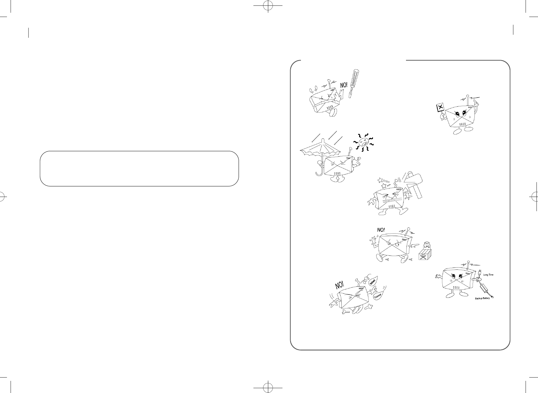
Do not disassemble
or revise the FWT terminal
at your discretion
Do not touch
the antenna during
c a l l i n g
Do not use the FWT terminal at hot
and humid places. It may not be repairable
if wet by rain or drinks
Avoid vibration or impact
and keep the FWT terminal
at a safe place to avoid
damage while you are not
using it
Do not use the FWT terminal
at a place where explosives
or flammable liquids are
p r e s e n t
Do not wipe the FWT terminal
with chemicals such as solvent
Remove the SMPS and the
backup battery if you do not
use the FWT terminal for
a long time
P recautions in using
HWT-2150
User Guide 5
B e f o re Using
This product is the Fixed Wireless Terminal (FWT) designed using
the up-to-date communication technology Code Division Multiple
Access(CDMA) to fulfill superior communication services of users.
Please, review this manual closely before using the product.
Caution : As the backup battery of the FWT is not connected to the
terminal upon delivery,make sure to connect it properly,
referring to “General installation” of this manual.
Before Using
4
hWT-2150(8-9) 2003.8.9 11:51 AM 페이지5
Function Description of Each Component
•POWER LED
Lighted when the external power is applied.
- When the external power is applied, the L E D is red.
- When the internal power is applied, the LED is green.
- If the backup battery is connected, you can use the terminal without
the external power supply.
•S E RVICE LED
Indicates status of the backup battery.
- LED OFF : Indicates that the service is not available as the
receive power intensity is weak.
- LED blinking: Indicates that the service available although the
receive power intensity is weak.
- LED ON : Indicates that the receive power intensity is strong
and the service is available.
•MODE LED
- R E D : Indicates that the state is Voice Ca l l .
- Green : indicates that the state is Data Se r v i c e .
- Yellow : Indicates that the state is FAX Ca l l .
-LED OFF : Indicates that the state is stand by.
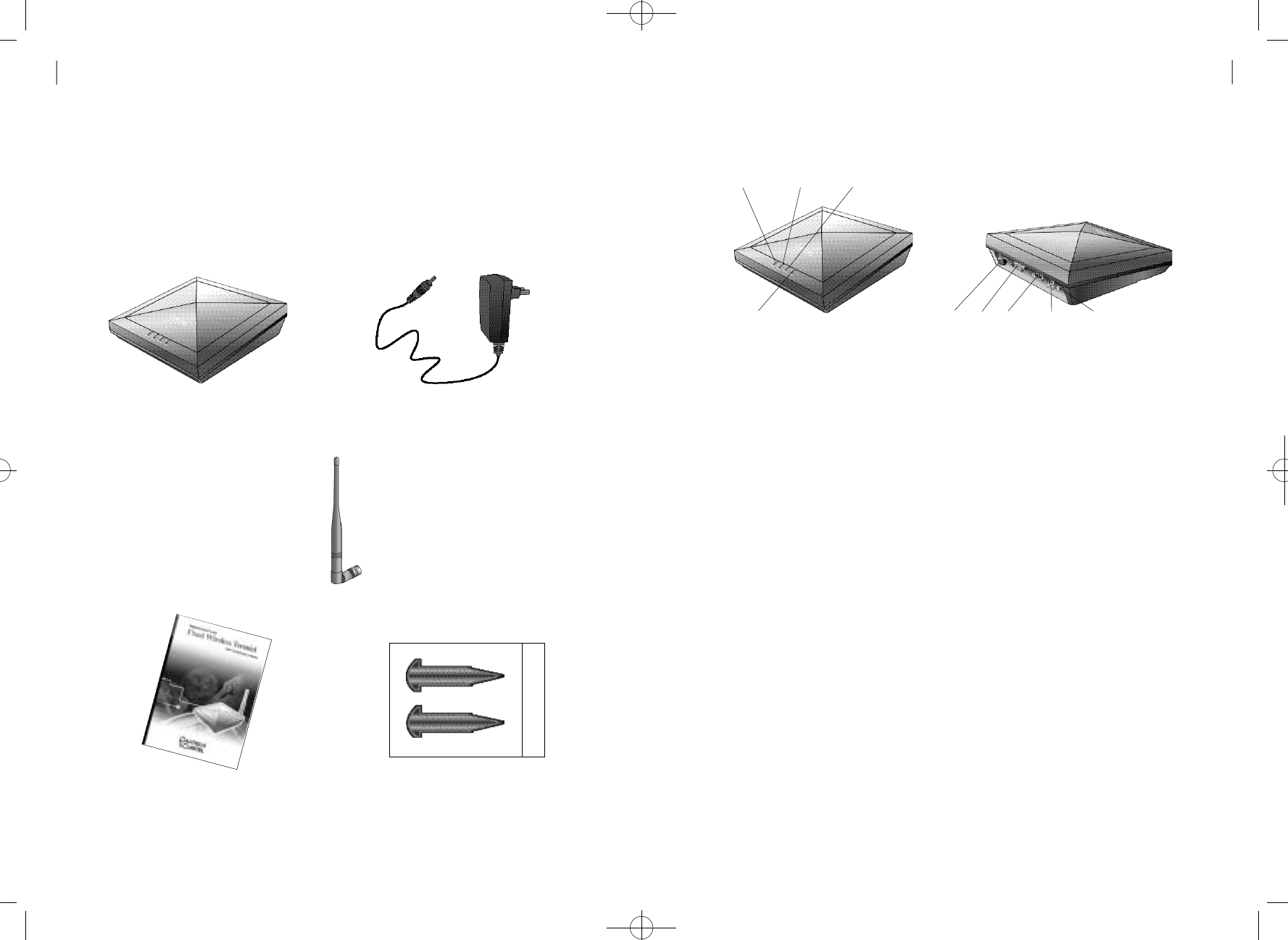
Thank you for purchasing this product. Please check if the
components of the product are consistent with the figure below :
Components ch e ck
FWT terminal
Antenna
Power supply (SMPS)
user Guide Fixation Nuts
HWT-2150
User Guide 7
Before Using
6
POWER LED SERVICE LED MODELED
CHGLED Serial
ANT. RJ-11 DC Jack Power Button
hWT-2150(8-9) 2003.8.9 11:51 AM 페이지7
Installation
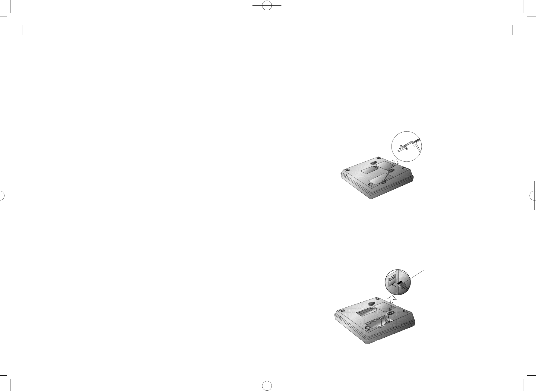
G e n e r al installat i o n
1. Set the battery switch located at the bottom of the terminal to Off .
2. As shown in the figure below, open the cover on the rear side of
the terminal by pushing it along the arrow.
3. After the cover is open, you can see the backup battery and its
c o n n e c t o r. As shown in the figure below, grip the connector to let
the flat side look downward. Then, push the connector along
the arrow to connect it to the circuit board.
•CHG LED
- R E D : indicates that the state is in Ch a r g i n g .
•DC JACK
Feeds power from the SMPS of the FWT terminal.
- The AC input of the SMPS ranges 90~270V
•SERIAL PORT
A port for maintenance and data communication of the FWT terminal
•R J - 11 JACK
Used to connect normal phones.
- As two jacks are presented, you can concurrently connect two
telephones without security assured.
- You may connect one telephone to any of the two jacks.
- You may connect up to five telephones to RJ-11 jack.
•POWER SWITCH
Connects power to the FWT terminal.
HWT-2150
User Guide 9
Before Using
8
backup battery connector
hWT-2150(8-9) 2003.8.9 11:51 AM 페이지9
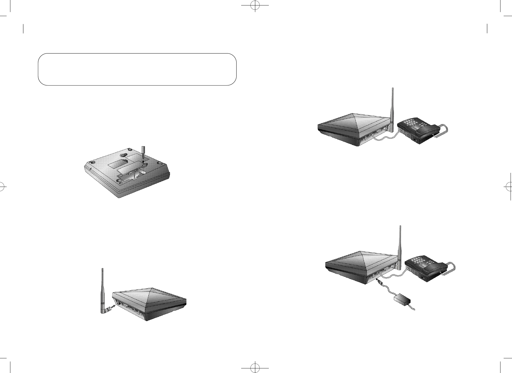
6. As shown in the figure below, connect the telephone (normal phone)
to the jack RJ-11. You may use any of the two RJ-11 jacks provided
by the terminal.
7. Connect the SMPS for FWT terminal to the DC-jack located on the left
side of the terminal. Insert the power jack properly until it does not move
f u r t h e r.
N o t e : The terminal may be damaged if you attach the connector
opposite to the direction shown above. Please double-check
the direction and proceed to step 4
4. After connecting the battery connector to the circuit board, insert the
cover as shown in the figure below. Then, fix the cover with
the screws.
5. As shown in the figure below, insert the antenna along the arrow and
rotate it clock-wise.
HWT-2150
User Guide
Installation
1 0 11
hWT-2150(8-9) 2003.8.9 11:51 AM 페이지11
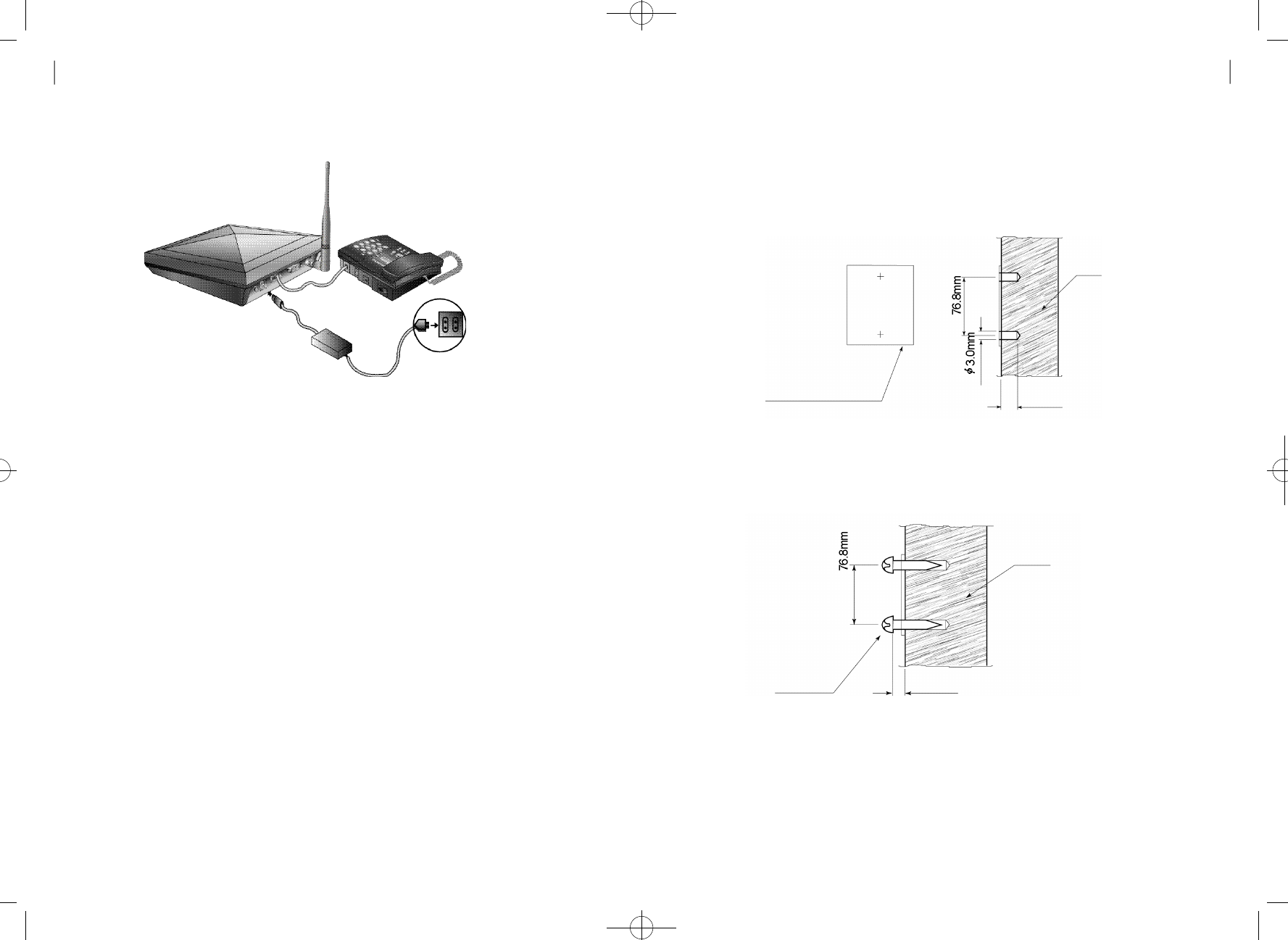
Wall bracket Installation
1. In case of concrete wall, attach the Installation Sheet to the place
that you want and make holes with a drill.
2. As shown in the figure below, fix the screws into the holes.
※In case of wooden wall, skip drilling and directly fix the screws to the
Installation Sheet. The distance from the wall to the head of the
screw is the same as the figure in step 2.
Installation Sheet
Wall
Wall
25.0mm
3.5mm
Screw
8. Connect the power plug of the SMPS to the power receptacle.
9. Set the power switch located at the back of the terminal to ON.
The following actions occur :
•All of the four LEDs are lighted, and then the LED corresponding
to the power currently applied is lighted.
•If the service available, the SERVICE LED is lighted.
AC plug
(110V or 220V)
HWT-2150
User Guide 13
Installation
1 2
hWT-2150(8-9) 2003.8.9 11:51 AM 페이지13
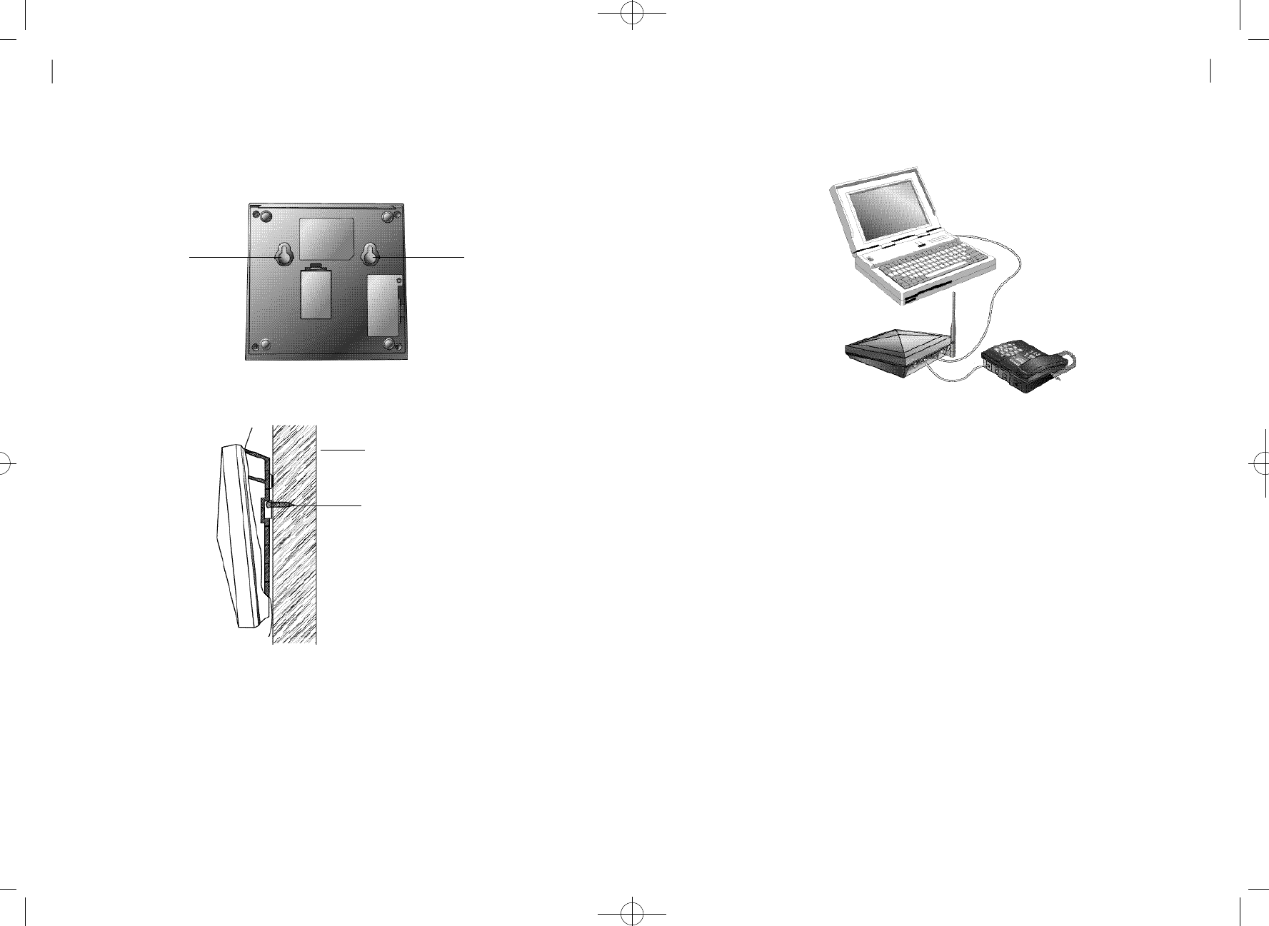
3. As shown in the figure below, insert A1 and A2 of the terminal to the
head of the screw and press the terminal downward to fix it.
W a l l
Screw required to
tighten the terminal
to the wall.
A1 A2
4.The following figure shows the shape after completion of Installation.
HWT-2150
User Guide 1 5
Installation
1 4
※You can get a batter call quality by installing the external panel antenna
(Please contact the distributor of the product for the antenna).
※The FWT terminal has a backup battery to run without the external power
s u p p l y. If the SMPS for the FWT terminal is down, the terminal can run for
about 15 hours in waiting state and for about 2 hours in call state with
the backup battery.
Installation for data service
As shown in the figure above, connect the serial port of the FWT terminal
to the PC COM1(COM2) with the RS232 cable. Data service subscribers
can purchase the RS232 cable from the service provider.
<FWT-PC connection for data service>
Computer
RS-232 Cable
WLL
Terminal
Telephone
hWT-2150(8-9) 2003.8.9 11:51 AM 페이지15

Operation
Power On
- Using the external power
Connect the SMPS to the DC-Jack located on the left side of the
terminal and insert the power plug of the SMPS to the receptacle.
Insert the power jack properly until it does not move further. If power
is applied to the terminal, all of the four LEDs are lighted. Then, the
power LED is lighted and the service LED is lighted if the service
a v a i l a b l e .
- Using the backup battery
To use the backup battery of the terminal, set the battery switch at
the bottom to On. If you want to use the backup battery, it has to be
charged enough to operate the terminal. The battery is automatically
charged when the external power is applied. If power is applied to
the terminal, all of the three LEDs are lighted. Then, the battery LED
located at the center is lighted and the service LED located at the
bottom is lighted if the service available.
Power Off
Turn off the power switch located at the back of the terminal.
Call Send
- Normal Procedure
①Pick up the handset in on-hook status. You will hear the dial tone
(In case of No Service, you will hear the warning tone with 0.5Sec
i n t e r v a l ) .
HWT-2150
User Guide 1 7
Operation
1 6
②You can not send calls in No Service status (Service LED off ) .
③Press the phone number of the called party and click the hook
switch (Hook-Flash).
④Speak to the called party when the line is connected.
⑤Hang up the handset after conversation.
- Redialing
Used to call to the phone number called latest.
①Pick up the handset and click the hook switch. The line is
connected to the number called latest. This function would not
work if you tried no call after power on
②Pick up the handset and click the hook switch. Refer to section
4.7 for the click time.
③Hang up the handset after conversation.
- Speed Dialing
Before using this service, you have to set the speed dial function.
Refer to Section 4.1 for the setting method.
①In case of one digit
If the speed dial is 01_09, pick up the handset, press the number
(1_9), and then click the hook switch or press the latter digit long.
Speak to the called party when the line is connected. Hang up the
handset after conversation.
②In case of two digits
If the speed dial is 10_99, pick up the handset, press the number
(10_99), and then click the hook switch or press the first digit short
and second digit long.
Speak to the called party when the line is connected. Hang up the
handset after conversation.
hWT-2150(8-9) 2003.8.9 11:51 AM 페이지17

Call Re c e i ve
- When the Normal Phone is On-hook State
①Pick up the handset when the normal phone rings.
②Speak to the called party when the line is connected.
③Hang up the handset after conversation.
- When the Normal Phone is Off-hook State
①Click the hook switch(hook-flash) if the normal phone receives the
ring signal (Call receive in off-hook is allowed only if the dial tone
& warning tone are being sent and the bell rings through the
b u z z e r ) .
②Speak to the called party when the line is connected.
③Hang up the handset after conversation
A n a l o g G3 Fax Serv i c e
To use the analog G3 fax service from the terminal equipped with the
analog G3 fax board, you have to send/receive documents
according to the following procedure:
- Sending Documents
Press [✽00] and then press the number of destination. The other
procedure is the same as that for general faxes.
- Receiving Documents
To receive documents from the analog G3 fax, set the terminal to the
Analog G3 fax receive mode first. Pick up the handset of the fax and
press [✽✽✽✽1 5 ✽]. The fax is set to the Analog G3 fax receive
mode(Set to Analog G3 fax receive mode until power off ) .
You can not receive voices unless you reset the Analog G3 fax
receive mode. To reset the Analog G3 fax receive mode, pick up the
HWT-2150
User Guide 1 9
Operation
1 8
handset of the fax and press [✽✽✽✽1 0 ✽]
D ata Serv i c e
When a PC is connected to the WLL terminal, the data service can
provide Internet and PC communication and fax send/receive. As
wireless data communication service may not be provided
depending on service providers, please check if the service provider
provides this service. This service is available after purchasing data
communication cable from the service provider.
For computer environment setup and other details, refer to the User
Manual provided when you purchase the data communication cable.
- Data Service Receive Mode Setting
•Setting with a normal phone
This function is used to set the receive mode according to data
service type, using the normal phone connected to the W L L
t e r m i n a l
①Pick up the handset of the normal phone and press
[✽✽✽✽1 0✽] to reset the data service receive mode.
②Pick up the handset of the normal phone and press
[✽✽✽✽11✽] to set fax receive mode(one time).
The fax receive mode is released automatically 10 minutes after
s e t t i n g .
③Pick up the handset of the normal phone and press
[✽✽✽✽1 2✽] to set fax receive mode
(Set to fax receive mode until power off ) .
④Pick up the handset of the normal phone and press
[✽✽✽✽1 3✽] to set modem receive mode(one time).
The modem receive mode is released automatically 10 minutes
after setting.
⑤Pick up the handset of the normal phone and press
[✽✽✽✽1 4✽] to set modem receive mode
hWT-2150(8-9) 2003.8.9 11:51 AM 페이지19

(Set to modem receive mode until power off ) .
⑥Default setting is [✽✽✽✽1 0✽] .
•Setting with AT commands
This function is used to set the receiving mode according to data
service type,using the communication emulator program of PC
connected to the WLL terminal.
①Enter [AT +Q CVAD=0] in the communication emulator program
and press the Enter key.
・After the setting is completed, OK is indicated and the data service
receive mode is released.
②Enter [AT +Q CVAD=1] in the communication emulator program
and press the Enter key.
・After the setting is completed, OK is indicated and the fax receive
mode (one time) is set. The fax receive mode is released
automatically 10 minutes after setting.
③Enter [AT +Q CVAD=2] in the communication emulator program
and press the Enter key.
・After the setting is completed, OK is indicated and the fax receive
mode is set (Set to fax receive mode until power off ) .
④Enter [AT +Q CVAD=3] in the communication emulator program
and press the Enter key.
・After the setting is completed, OK is indicated and the modem
receive mode is set (one time). The modem receive mode is
released automatically 10 minutes after setting.
⑤Enter [AT +Q CVAD=4] in the communication emulator program
and press the Enter key.
After the setting is completed, OK is indicated and the modem
receive mode is set (Set to modem receive mode until power off ) .
⑥Default setting is [AT +Q CVA D = 0 ] .
HWT-2150
User Guide 2 1
Operation
2 0
Supplement Service
Speed dial
This function is used to save frequently used phone numbers in
advance and make a phone call quickly with the abbreviated code.
You can save up to 99 phone numbers. Default setting is off .
- Save phone number
Enter [##3233→1→1], enter a two-digit numbers(01~99) for the
address to save the phone number and press the [✽] button(save).
# # 3 2 3 3→1→1→address(2 digits)→phone numbers→✽
: save phone numbers
- Delete phone number
Enter [##3233→1→2], enter the address(01~99) to delete and press
[✽] button. To delete all phone numbers saved, enter [##3233→1→
3] and press the [✽] button.
##3233 →1 →2 →address(2 digits) → ✽ : delete one address
##3233 →1 →3 →✽ : delete all address
- Speed dial on and off
Enter [##3233→1→4] and then press the [✽] button(on). The speed
dial mode is enabled only if the speed dial function is on although
phone numbers are saved in the memory.
To disable the function(off), enter [##3233→1→5] and then press
the [✽] button.
hWT-2150(8-9) 2003.8.9 11:51 AM 페이지21

HWT-2150
User Guide 2 3
Supplement Service
2 2
##3233 →1 →4 → ✽ : speed dial on
##3233 →1 →5 → ✽ : speed dial off
- Speed Dialing
If the phone number is saved in the address and the speed dial function
is enabled(on), you can make a phone call by entering just the address.
If the saved address is one digit(01~09), press the latter digit long or
press it short and click the hook switch to make a phone call to the
saved number.
If the saved address is two digits(10~99), press the first digit short and
the second digit long or press the two digits short and click the hook
switch to make a phone call to the saved number.
If you attempt a call while the speed dial function is off, you will hear the
reject tone and fail to make a phone call.
E m e rge n c y call hold
This function is used to register up to three phone numbers(Address
01~03) in advance to prepare for emergencies and quickly make a
phone call with the speed dial. The line connected is held on as long as
the called party does not release. Default setting is off .
- Emergency call hold on and off
Enter [##3233 →1 →6] and press [✽] button(on). The emergency call
hold function is activated when phone numbers are saved in address
01~03 and the emergency call is on. You can save phone numbers in
address 01~03 in the same way as "4.1.1" .
To deactivate the emergency call hold function(off), enter [##3233 →1 →
7] and press the [✽] button.
Reference: Warning Tone/Howler(ROH:Receiver Off-Hook) Tone
If you pick up the handset (Off-Hook) and do not press buttons for the given time, the
dial tone changes to the warning tone. At this time, you can receive calls but can not
send calls as number input is not allowed. In this case, you have to put back the handset
(On-Hook) and pick it up again (Off-Hook) to attempt a call. If you hold the handset
after the dial tone has changed to the warning tone, the warning tone changes to the
Howler (ROH) Tone after the given time. You can hear the Howler Tone through the
buzzer. From that time on, you can not send or receive calls until you hang up (On-
Hook) the handset.
##3233 →1 →6 →✽ : emergency call hold on
##3233 →1 →7 →✽ : emergency call hold off
- Emergency call
When phone numbers are stored in address 01~03 and the
emergency call is on, if you press the latter digits of the address long
or two digits short and click the hook switch, the call is connected to
the stored number and is held on as long as the called party does not
r e l e a s e .
If you attempt speed dialing when emergency call hold and speed dial
are enabled concurrently, the address 01~03 are operated in
emergency call hold mode.
If you attempt speed dialing when emergency call hold is off and
speed dial is on, the address 01~03 are operated in speed dial mode.
Reference: Confirmation Tone/Reject Tone
If you press the [✽] button(save) after all key operation for supplementary service
setting is normally accomplished, the telephone returns to the initial status after hook-
off and the Confirmation Tone is sent to notify that the setting has been accomplished
normally. If an incorrect key is entered, a short reject tone is sent to notify the error.
Then, you can continue the operation from that step.
hWT-2150(8-9) 2003.8.9 11:51 AM 페이지23
HWT-2150
User Guide 2 5
Supplement Service
2 4
Hot Line Serv i c e
This function is used to register one frequently used number
(address 99) in advance and automatically make a phone call to
the number after hook-off. Default setting is Off .
Hot line is operated in 2 modes; timed hot line mode to connect
the line after the specified time (4sec~8sec) and immediate hot
line mode to connect the line just after off - h o o k .
- Hot line on and off
Enter [##3233→1→8→1].and press the [✽] button to set timed
hot line(On).
If a phone number is saved in addess 99 and the hot line function
is set to timed hot line mode, the line is connected the dial send
time (4sec~8sec) after hook-off .
Also, enter [##3233→1→8→2].and press the [✽] button to set
immediate hot line(On).
If a phone number is saved in address 99 and the hot line function
is set to immediate hot line mode, the line is connected just after
hook- off.
##3233 →1 →8 →1 →✽ : Timed hot line on
##3233 →1 →8 →2→✽ : Immediate hot line on
##3233 →1 →8 →3→✽ : Hot line off
- Hot line calling
If a phone number is saved in address 99 and the hot line
function is set to timed hot line mode, the line is connected the
dial send time(4sec~8sec) after hook-off. Also, if a phone number is
saved in address 99 and the hot line function is set to immediate hot
line mode, the line is connected just after hook-off .
A l a rm reminder
If you set a time in advance, the alarm rings on the specified time
and stops when you pick up the handset. Default setting is off .
- Alarm reminder on and off
Enter [##3233→2→1] and four digits for a desired time(24 hours) and
press the [✽] button(on).
The alarm reminder function is automatically set to one time. The
alarm rings on the specified time and then the alarm reminder is
released (off ) .
If you want to activate the alarm at the same time everyday, enter
[ # # 3 2 3 3→2→3→✽] to activate the alarm reminder and enter
[ # # 3 2 3 3 →2→4→✽] to deactivate it.
##3233 →2 →1 →Hour(4 digits, 24 hours) → ✽
: Alarm time input and setting (one time)
##3233 →2 →2 → ✽ : Alarm reminder on (one t i m e )
##3233 →2 →3 →✽ : Alarm reminder on (always)
##3233 →2 →4 → ✽ : Alarm reminder off
R e f e r e n c e :
When immediate hot line is on, you can not send calls to other numbers.
To make a phone call to other number, enter the setup mode by pressing the [#] button
within one second after hook-off and change the hot line mode.
hWT-2150(8-9) 2003.8.9 11:51 AM 페이지25
HWT-2150
User Guide 2 7
Supplement Service
2 6
L o ck
This function is used to enter a password into the terminal to reject
calls from users who are not aware of the password.
If you attempt a call when the lock function is on, the warning tone is
heard and the call is not connected (Call receive is allowed).
H o w e v e r, if the emergency call function is on, origination of
emergency calls (address 01~03) is allowed. Default setting is off .
- Lock on and off
Enter [##3233→3] and a password of four digits. If you enter an
incorrect password, you will hear the reject tone. If the correct
password is entered, press [1] and then the [✽] button(lock on). To
release the lock function, enter [##3233→3→p a s s w o r d→2→✽] .
##3233 →3 →password →1 → ✽ : Locking on
##3233 →3 →password →2 → ✽ : Locking off
- Password change
To change the password, press [##3233→3] and then enter the
password. Press[3], enter a new password and press the [✽] b u t t o n .
Enter the new password again and press the [✽] button to change
the password to the new one.
##3233 →3 →password →3→new password →✽→new password→✽
: change password
R e f e r e n c e : The default password for lock is "0000".
E a r -piece volume contro l
Used to control the volume of ear-piece. Default setting is Level3
[#### 03].
- Ear-piece volume control method
①Enter [##3233 →4 →1], enter a desired button out of 1(level 1),
2(level 2), 3(level 3), 4(level 4), 5(level 5), and then press the [✽]
button to save.
"1" is the smallest volume. The bigger the number is, the larger
the volume is.
# # 3 2 3 3→4→1→1 ~ 5 →✽: Ear-piece volume(Method 1)
②Pick up the handset of the normal phone and press [####]. Enter
a desired number out of 01~05, and then press the [✽] button to
save. You will hear the dial tone after the volume control is
c o m p l e t e d .
#### →01~05 →✽: Ear-piece volume control (method 2)
Reset
Used to reset the terminal setup.
- Reset method
①Enter [##3233→4→0] and the lock code or the maintenance
code and then press [✽] button.
##3233 →4 →0 →✽ : Reset
hWT-2150(8-9) 2003.8.9 11:51 AM 페이지27

HWT-2150
User Guide 2 9
Supplement Service
2 8
Reset items and their status are listed below:
CLIP Setting
As the terminal type FWT has no display, the calling party’s number
can be indicated by connecting a specific module or a display type
telephone. This function is used to set communication method of the
m o d u l e .
- CLIP Setting Method
①Enter [##3233 →5 →Maintenance Code →1 →1(DTMF
mode) or 2 (FSK mode)] and press the [✽] button to save.
##3233 →5 →Maintenance Code →1 →1 or 2→ ✽
: CLIP setting
I t e m s S t a t u s
Speed dial
E m e r gency call hold
Hot line call
A l a r m
L o c k
E a r -piece volume
o f f
o f f
o f f
o f f
o f f
level 3
R e f e r e n c e : The Maintenance Code “2733” is used only for maintenance.
A n a l o g G3 Fax Standard Setting
The terminal can provide fax service using two types of Analog G3
Fax standards.
This function is used to set the standard.
- Analog G3 Fax Standard Setting
Analog G3 Fax service is provided using the IS-99/IS-707.4 based
PC Fax standard or the IS-707A.7 Analog G3 Fax standard. When
IS-99/IS-707.4 based PC Fax standard is used, you have to select
the default Fax receiving mode.
①IS-99/707.4 PC Fax setting
Enter [##3233 →5 →Maintenance Code →2 →1], select “1”
(PC fax) or “2” (Analog G3 Fax), and then press the [✽] button to
s a v e .
##3233 →5 →Maintenance Code →2 →1 →1 or 2 →✽
: IS-99/707.4 PC Fax based mode setting
R e f e r e n c e : Default receiving mode is system-dependent (Unnecessary depending on
system configuration.). If the system is configured with single DN, the default receiving
mode is not applied as Fax receiving depends on user’s receive mode setting (Data
receiving through the analog G3 Fax in case of ****15* and through the PC in case of
****12*). Also, if the system is configured with two DNs (if fax calls are received
according to the service option determined by the system), the terminal receives calls
according to the default receiving mode setting.
hWT-2150(8-9) 2003.8.9 11:51 AM 페이지29

HWT-2150
User Guide
3 1
Supplement Service
3 0
②IS-707A.7 Analog G3 Fax standard setting.
Enter [##3233 →5 →Maintenance Code →2 →2] and press
the [✽]button to save.
##3233 →5 →Maintenance Code →2 →2 →✽
: IS-707A.7 Analog G3 Fax standard setting
D e fault Data Rate Setting
The terminal supports two types of data rates according to the
s t a n d a r d s .
This function is used to set the default rate for data calls.
- Default Data Rate Setting
①Setting IS-99 Rate Set 1 : Enter [##3233 →5 →Maintenance
Code →3], select “1”, and then press the [✽] button to save.
##3233 →5 →Maintenance Code →3 →1 →✽
: Setting default data rate (8K) to RS1 (IS99)
②Setting IS-99 Rate Set 2: Enter [##3233 →5 →Maintenance
Code →3], select “2”, and then press the [✽] button to save.
##3233 →5 →Maintenance Code →3 →2 → ✽
: Setting default data rate to RS2 (IS-99 based)
③Setting IS-707.4 Rate Set 1 : Enter [##3233 →5 →Maintenance
Code →3], select “3”, and then press the [✽] button to save.
##3233 →5 →Maintenance Code →3 →3 →✽
: Setting default data rate to RS1(IS-707.4 based)
④Setting IS-707.4 Rate Set 2 : Enter [##3233 →5 →Maintenance
Code →4], select “4”, and then press the [✽] button to save.
##3233 →5 →Maintenance Code →3 →4 →✽
: Setting default data rate to RS2(IS-707.4 based)
R i n ger Fre q u e n c y & Cadence Control
This function is used to control the ringer frequency and cadence.
Select the frequency first and then select the cadence. Default
setting is 20Hz, 1 sec On – 2sec Off .
- Ringer Frequency Setting
Enter [##3233 →5 →Maintenance Code →4]. Select a desired
number from 1 (16Hz) , 2 (20Hz) and 3 (25Hz).
- Ringer Cadence Setting
After selecting the frequency, select the cadence. Select a
desired number from 1~ 6 and press the * button to terminate
ringer frequency and ringer cadence setting.
No. 1: 1Sec On – 2 Sec Off
No. 2: 0.4 Sec On – 0.2 Sec Off - 0.4 Sec On – 2 Sec Off
No. 3: 1 Sec On – 4.5 Sec Off
No. 4: 1 Sec On – 4 Sec Off
hWT-2150(8-9) 2003.8.9 11:51 AM 페이지31

HWT-2150
User Guide
3 3
Supplement Service
3 2
No. 5: 0.25 Sec On – 0.25 Sec Off - 0.25 Sec On – 1.25 Sec Off
No. 6: 2 Sec On – 4 Sec Off
##3233 →4 →3 →1~3(frequency) →1~6(cadence) →✽
: Ringer frequency & cadence setting
Dial Tone Fre q u e n c y Control
This function is used to select the dial sent from the handset. Default
setting is 350 + 440Hz dual tone.
- Dial Tone Frequency Control Method
①Enter [##3233 →5 →Maintenance Code →5 ] .
Select a desired number from 1 (350+440Hz) , 2 (400Hz) ,
3 (425Hz) and 4 (450Hz) and press the [✽] button.
##3233 →5 →Maintenance Code →5 →1~4 → ✽
: Dial Tone Frequency Control (Method 1)
②Pick up the handset of the normal phone, press [####], and enter
a desired number out of 51 (350+440Hz) , 52(400Hz) , 53(425Hz)
and 54(450Hz).
#### →51~54 : Dial Tone Frequency Control (Method 2)
D e fault Vocoder Selection
The terminal provides service with three Vocorder types.
This function is used to select the Vocorder type.
- Vocoder Selection Method
Enter [##3233 →5 →Maintenance Code →6], select one of “1”
(8K EVRC) or “2” (13K QC E L P ) and then press the [✽] button to
s a v e .
##3233 →5 →Maintenance Code →6 →1 or 2 →✽
: Vocoder selection
Timed Hot Line Dial Send Waiting Time
C o n t ro l
This function is used to control the hot line number send time when
the Timed Hot Line is On. The Hot Line number send time is
adjustable from 4 sec to 8 sec and default setting is 6 sec.
- Timed Hot Line Dial Send Waiting Time Setting
①Enter [##3233 →5 →Maintenance Code →7 ] .
Select a desired number from 4 , 5 , 6 , 7 and 8 and press the [✽]
b u t t o n .
For example, to set 7 sec, press 7 and the [✽] button.
##3233 →5 →Maintenance Code →7 →4~8 →✽
: Timed Hot Line Dial send time setting (Method 1)
hWT-2150(8-9) 2003.8.9 11:51 AM 페이지33

HWT-2150
User Guide
3 5
Supplement Service
3 4
②Pick up the handset of the normal phone, press [####], and then
select a desired number from 04~08. ‘04’ indicates automatic call
send after 4 seconds and ‘08’ indicates automatic call send after
eight seconds.
#### →04~08
: Timed Hot Line Dial send time setting (Method 2)
Hook Flash Time (Click Time) Control
This function is used to set the time required to recognize click of the
hook switch for redial and speed dial. Default setting is 100-700ms.
- Hook Flash Time Control Method
①Enter [##3233 →5 →Maintenance Code →8 →1], enter two
digits (05~98) for the minimum time by the 10msec, and then
press the [✽] button to save.
##3233 →5 →Maintenance Code →8 →1 →05~98 → ✽
: Hook Flash minimum time setting
②Enter [##3233 →5 →Maintenance Code →8 →2], enter two
digits (06~99) for the maximum time by the 10msec, and then
press the [✽] button to save.
##3233 →5 →Maintenance Code →8 →2 →06~99 →✽
: Hook Flash maximum time setting
R e f e r e n c e : If the minimum time is set to 50 ~ 90 msec, it is not available for dial pulse
type telephones.
Voice Priva cy Setting
The terminal supports voice privacy.
- Voice Privacy On
Enter [##3233 →5 →Maintenance Code →9 →1] and press the
[✽] button to save.
- Voice Privacy Off
Enter [##3233 →5 →Maintenance Code →9 →2] and press the
[✽] button to save.
##3233 →5 →Maintenance Code →9 →1 or 2 →✽
: Voice Privacy on/off
Serial Interface Setting (None for HWP- 2 1 5 0 )
The terminal supports data serve when it is connected to the PC
through RS-232 serial interface. The HWT-2150 terminal provides
two data rates for PC interface. It provides 115200 bps for high-
speed packet data service and 19200 bps for modem, PC Fax and
low speed packet data service.
- Setting serial interface to 19200 bps
①Enter [##3233 →5 →Maintenance Code →0, select “1”], and
then press the [✽] button to save.
##3233 →5 →Maintenance Code →0 →1 → ✽
: Setting the serial data baudrate to 19200 bps
hWT-2150(8-9) 2003.8.9 11:51 AM 페이지35

HWT-2150
User Guide
3 7
Supplement Service
3 6
- Setting Serial Interface to 115200 bps
Enter [##3233 →5 →Maintenance Code →0, select “2”], and then
press the [✽] button to save.
##3233 →5 →Maintenance Code →0 →2 →✽
: Setting the serial data baudrate to 115200 bps
A Key Value Input
The terminal supports OTASP service that requires authentication.
This function is used to enter A key value required for the
authentication procedure.
- A Key Input
Enter [##3233 →6 →Maintenance Code →1], enter a number
corresponding to the A Key value up to 26 digits, and then press the
[✽]button to save.
##3233 →6 →Maintenance Code →1 →
A Key No.(26 digits) → ✽
: A Key input
N e t wo rk Dial Tone Setting
The terminal provides the network dial tone depending on
configuration of the system (system dependent). The terminal
connected to a system that provides the network dial tone provides
“LE-Generated dial tone”. Other systems provide “NIU-generated
dial tone”.
- Network Dial Tone Off
Enter [##3233 →6 →Maintenance Code →2, select “1”], and then
press the [✽] button to save.
##3233 →6 →Maintenance Code →2 →1 →✽
: NIU-generated dial tone setting
- Network Dial Tone On
Enter [##3233 →6 →Maintenance Code →2, select “2”], and then
press the [✽] button to save.
##3233 →6 →Maintenance Code →2 →2 → ✽
: LE-Generated dial tone setting
System Pa rameter Input
You can enter/change channel number and MIN number of the
system parameters with the handset.
- Channel Number Input
Enter ##3233 →9 →Maintenance Code →1~4, enter three digits
of the channel number, and then press the [✽] button to save.
1 : Primary System A channel
2 : Secondary System A channel
3 : Primary System B channel
4 : Secondary System B channel
##3233 →9 →Maintenance Code →1~4 →Channel No. → ✽
: Channel number input
hWT-2150(8-9) 2003.8.9 11:51 AM 페이지37
HWT-2150
User Guide
3 9
Supplement Service
3 8
- MIN Number Input
Enter ##3233 →9 →Maintenance Code →5, enter up to ten digits
for the MIN number, and then press the [✽] button to save.
##3233 →9 →Maintenance Code →5 →MIN No. → ✽
: MIN number input
A p p e n d i x
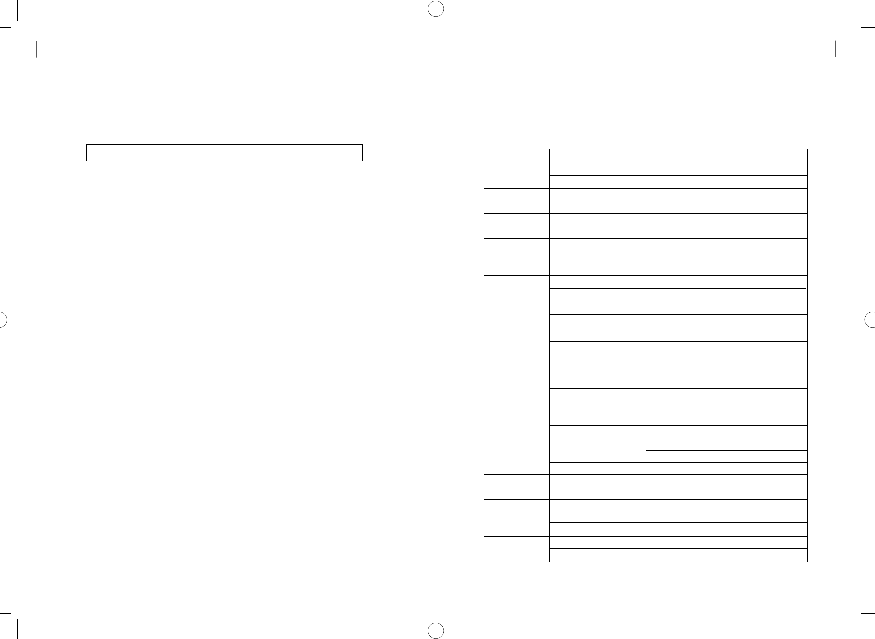
S u m m a ry tabl e
S a v e / d e l e t e
phone number
Speed dialing
Emergency call
h o l d
Hot line
Alarm reminder
L o c k
Ear-piece volume
adjusting ( 5 steps)
R e s e t
Clip setting
Analog G3 Fax
Standard Setting
Default Rate Set
Ringer Frequency &
Cadence Control
Dial Tone Frequency
C o n t r o l
S a v e
Delete one address
Delete all addresses
O n
O f f
O n
O f f
Time hot line on
Immediate hot line
O f f
Time input(one time)
One time mode
Always mode
Alarm off
O n
O f f
Change password
# # # # →01/02/03/04/05 →
✽
# # 3 2 3 3 →4→1→1 ~ 5 →
✽
# # 3 2 3 3 →4→0→p a s s w o r d →
✽
##3233 →5 →Maintenance Code →1 →1 / 2 →
✽
( 1 : DTMF(BINA) Mode, 2 : FSK Bellcore Mode)
IS-99/707.4 PC
Fax Mode
IS-707A.7 Mode
##3233
→
5
→
Maintenance Code
→
3
→
1 / 2 / 3 / 4
→
✽
(1 : RS 1 (IS99) , 2 : RS 2(IS99) , 3 : RS 1(IS707.4) , 2 : Rate Set 2 (IS707.4))
##3233
→
5
→
Maintenance Code
→
4
→
1 / 2 / 3 (frequency)
→
1 / 2 / 3 / 4 / 5 / 6 (cadence)
→
✽
(Frequency 1: 16Hz 2: 20Hz 3: 25Hz / Cadence 1,2,3,4,5, 6 : Refer to 4.8.2)
##3233
→
5
→
Maintenance Code
→
5
→
1 / 2 / 3 / 4
→
✽
( 1: 350+440Hz 2: 400Hz 3: 425Hz 4: 450Hz )
# # 3 2 3 3→1→1→a d d r e s s →phone number
# # 3 2 3 3→1→2→a d d r e s s →
✽
# # 3 2 3 3→1→3→
✽
# # 3 2 3 3→1→4→
✽
# # 3 2 3 3→1→5→
✽
# # 3 2 3 3→1→6→
✽
# # 3 2 3 3→1→7→
✽
# # 3 2 3 3→1→8→1→
✽
# # 3 2 3 3→1→8→2→
✽
# # 3 2 3 3→1→8→3→
✽
# # 3 2 3 3→2→1→hour(4 digits, 24 hours) →
# # 3 2 3 3→2→2→
✽
# # 3 2 3 3→2→3→
✽
# # 3 2 3 3→2→4→
✽
# # 3 2 3 3→3→p a s s w o r d →1→
✽
# # 3 2 3 3→3→p a s s w o r d →2→
✽
# # 3 2 3 3→3→p a s s w o r d →3→New p a s s w o r d →
✽
→
new p a s s w o r d →
✽
##3233 →5 →Maintenance Code →2 →1 →1 / 2 →
✽
( 1 : PC Fax receiving default , 2 : Analog G3 receiving default )
##3233
→
5
→
Maintenance Code
→
2
→
2
→
✽
(01:Min ←03:Middle →0 5 : M a x )
( 1 ~ 5 : s t e p 1 ~ s t e p 5 )
✽
hWT-2150(8-9) 2003.8.9 11:51 AM 페이지39
HWT-2150
User Guide
4 1
Appendix
40
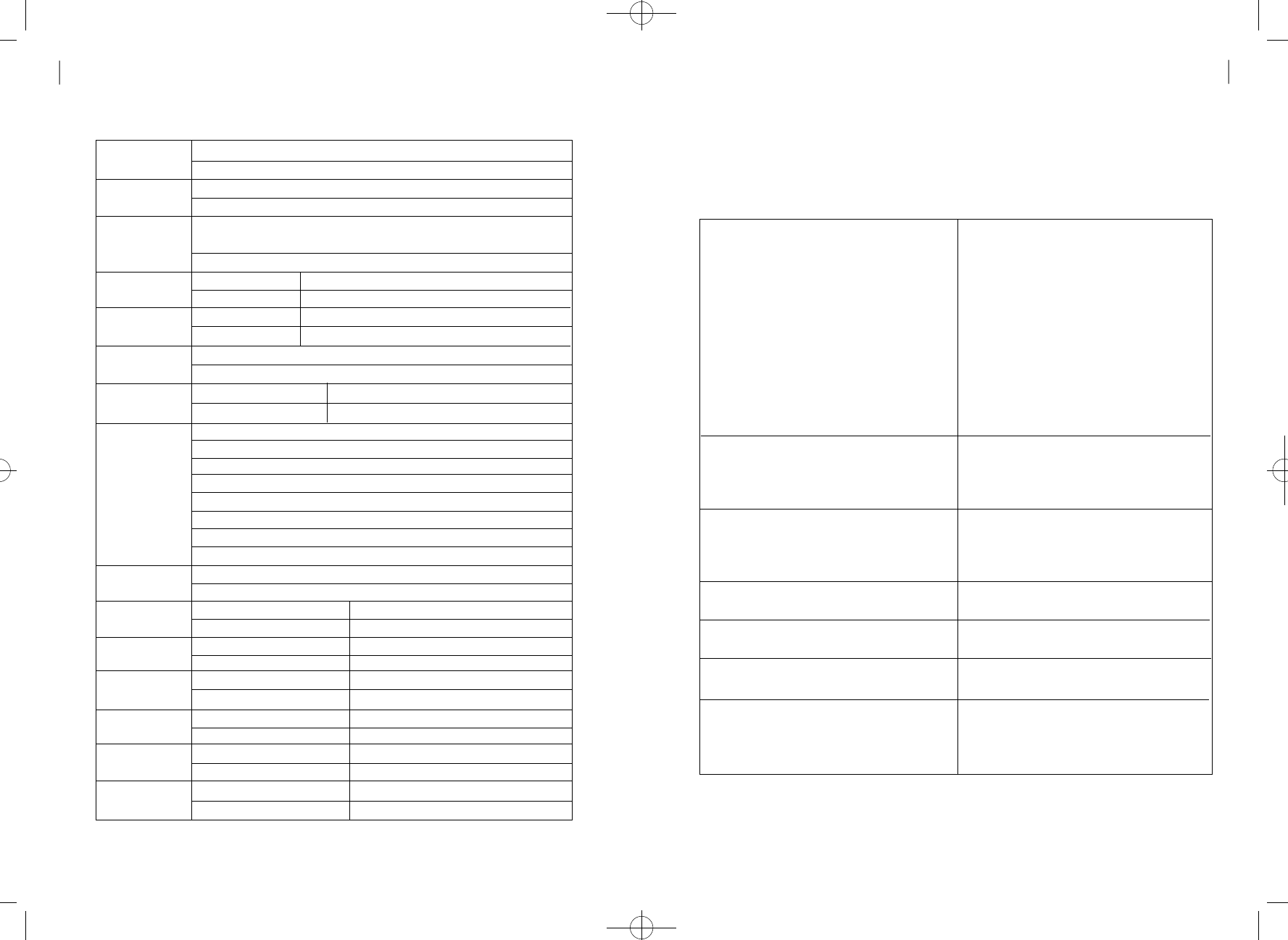
D e f a u l t
Vocoder S.O
Timed Hot Line Dial
Send Waiting Tim
Hook Flash
Time Control
Voice Privacy
Serial Interface
S e t t i n g
A Key Value
I n p u t
Network Dial
T o n e
C h a n n e l
Number Input
MIN Number
I n p u t
Analog G3 fax
r e c e i v e
Data service
receive mode release
Fax receive mode
setting (one time)
Fax receive mode
setting(until power off)
Modem receive
mode (one time)
Modem receive
mode(until power off)
##3233
→
5
→
Maintenance Code
→
6
→
1/ 2
→
✽
( 1 : 8K EVRC , 2 : 13K QC E L P )
##3233
→
5
→
Maintenance Code
→
7
→
4 / 5 / 6 / 7 / 8
→
✽
( 4: 4 Sec 5: 5 Sec 6: 6 Sec 7: 7 Sec 8: 8 Sec )
##3233
→
5
→
Maintenance Code
→
8
→
1 (Min time)
→
05~98
→
✽
##3233
→
5
→
Maintenance Code
→
8
→
2 (Max time)
→
06~99
→
✽
( 05 ~ 99 : 50 msec ~ 990 msec)
O n
O f f
19200 bps
115200 bps
##3233
→
6
→
Maintenance Code
→
1
→
“AKEY” (26 digits)
→
✽
( AKEY : 26-digit A Key value)
NIU-generated Dial Tone
LE-generated Dial Tone
# # 3 2 3 3
→
9
→
Maintenance Code
→
1(Primary A CH No.)
→
www (3digits)
→
✽
( www : Primary System A Channel No.)
# # 3 2 3 3
→
9
→
Maintenance Code
→
2(Secondary A CH No.)
→
xxx (3digits)
→
✽
( xxx : Secondary System A Channel No.)
# # 3 2 3 3
→
9
→
Maintenance Code
→
3(Primary B CH No.)
→
yyy (3digits)
→
✽
( yyy : Primary System B Channel No.)
# # 3 2 3 3
→
9
→
Maintenance Code
→
4(Secondary B CH No.)
→
zzz (3digits)
→
✽
( zzz : Secondary System B Channel No.)
# # 3 2 3 3
→
9
→
Maintenance Code
→
5
→
xxxxxxxxxx (10digits)
→
✽
( xxxxxxxxxx : MIN No.)
On (fax receive)
Off (voice receive)
Using the normal phone
Using the emulator
Using the normal phone
Using the emulator
Using the normal phone
Using the emulator
Using the normal phone
Using the emulator
Using the normal phone
Using the emulator
✽✽✽✽
1 5
✽
✽✽✽✽
1 0
✽
✽✽✽✽
1 0
✽
[ A T +
QC
VAD=0] →Enter key
✽✽✽✽
1 1
✽
[ A T +
QC
VAD=1] →Enter key
✽✽✽✽
1 2
✽
[ A T +
QC
VAD=2] →Enter key
✽✽✽✽
1 3
✽
[ A T +Q C VAD=3] →Enter key
✽✽✽✽
1 4
✽
[ A T +Q C VAD=4] →Enter key
##3233
→
5
→
Maintenance Code
→
9
→
1
→
✽
##3233
→
5
→
Maintenance Code
→
9
→
2
→
✽
##3233
→
5
→
Maintenance Code
→
0
→
1
→
✽
##3233
→
5
→
Maintenance Code
→
0
→
2
→
✽
##3233
→
6
→
Maintenance Code
→
1
→
1
→
✽
##3233
→
6
→
Maintenance Code
→
1
→
2
→
✽
Air Interface
Battery Back-up
Connectors for various
Service support
P h y s i c a l
E n v i r o n m e n t a l
Power Supply
A c c e s s o r i e s
Common air interface standard →IS-2000
FREQUENCY →TX : 824 – 849MHz
RX : 869 – 894MHz
TX Output Power →200mW
RX Sensitivity →- 104dBm
Vocoder →8K/13K QCELP, 8K EVRC
Channel Bandwidth →CDMA 1.25Mhz
Spurious →TX : -61dBm below
RX : -81dBm below
MOD/DEMOD →O QPSK/QPSK
Frequency Accuracy →Fo°
w
300Hz
Type →Ni-MH
Capacity →3.6V @ 1.8A
Talk Time →2 Hours
Standby Time →20Hours
RJ-11 →Standard wire-line telephone
Analog G3 Fax (Optional)
Serial port →Maintenance Purpose
Data Service Purpose ( Internet, PC Fax)
Dimension(D xW xH) →180 x180 x57mm
Weight ( including Backup battery) →546g
Operating Temperature →-10°C ~ +50°C
Storage Temperature →-20°C ~ +70°C
Input Power →100 ~ 240V
w10%,
48~62Hz
Output Power →5.5V 1.2A
Internal Antenna →Di-Pole Antenna
Power supply
External Antenna ( Optional ) →10dbi Gain
Directional Panel Antenna
Te chnical Specificat i o n
- 800MHz
hWT-2150(8-9) 2003.8.9 11:51 AM 페이지41
HWT-2150
User Guide
4 3
Appendix
42
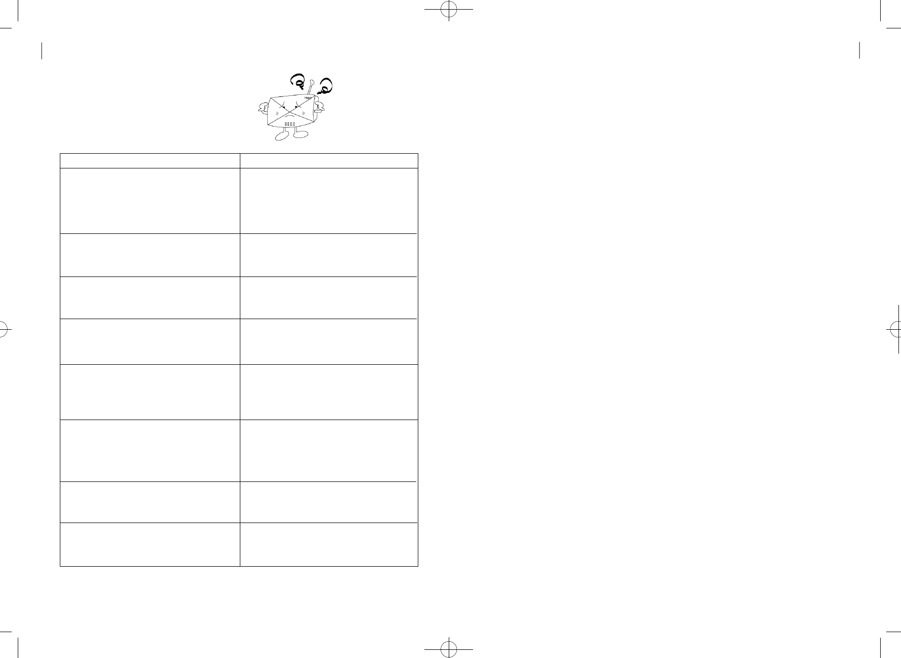
Tro u bl e s h o o t i n g
Trouble Actions
When you hear no sound after hook-off?
When the service LED blinks or goes off?
When you hear the warning tone instead of the
dial tone after hook-off?
When the warning tone sounds"beep beep" when
you attempts a call?
When calls are not connected with the warning
tone but you can receive calls?
When voice resounds during conversation?
When voice of the other party is not clear?
When the battery LED blinks or goes off while
you are operating the terminal with the battery?
•Check if the power LED or battery LED of the
terminal is on. If off, check if the SMPS power
plug is properly connected to the terminal.
•Check the RJ-11 Jack of the terminal connected
to the telephone.
•Check if the antenna is connected correctly, or
move the location of the terminal and check if
the service LED is on.
•Check if the antenna is connected correctly, or
move the location of the terminal and check if
the service LED is on.
•No call channel available or communication
failure with the base station. check if the service
LED is on and try again.
•The lock function is on. Refer to section
'Ear-piece Volume control' of the user guide.
•If you are not aware of the password, please
contact the distributor or the service center.
•The resound removing function of the base
station is set improperly. Refer to section
'Ear-piece Volume control' of the user guide
for volume control.
•Refer to section 'Ear-piece Volume control'
of the user guide.
•Charge the backup battery with the SMPS as
the battery is discharged.
S a fety Info rm at i o n
1 . SAFETY INFORMATION FOR FIXED WIRELESS TERMINALS
•P O T E N T I A L LY EXPLOSIVE AT M O S P H E R E S
Turn your phone OFF when in any area with a potentially explosive
atmosphere and obey all signs and instructions.Sparks in such areas could
caus e an explosion or fire resulting in bodily injury or even death.
•INTERFERENCE TO MEDICAL DIVICES
Certain electronic equipment may be shielded against RF signal from you
wireless phone.(pacemakers,Hearing Aids,and so on)
Turn your phone OFF in health care facilities when any regulations posted in
these areas instruct you to do so.
RF signals may affect improperly installed or inadequately shielded electronic
system in motor vehicles.
•EXPOSURE TO RF ENERGY
Use only the supplied or an approved replacement antenna.
Do not touch the antenna unnecessarily when the phone is in use.
Do not move the antenna close to, or touching any exposed part of the body
when making a call.
2 . SAR INFORMAT I O N
THIS MODEL PHONE MEETS THE GOVERNMENT ’S REQUIREMENTS
FOR EXPOSURE TO RADIO WAV E S .
Your wireless phone is a radio transmitter and receiver.It is designed and
manufactured not to exceed the emission limits for exposure to radio
frequency (RF)energy set by the Federal Communications Commission of the
U.S.Government.These limits are part of comprehensive guidelines and
establish permitted levels of RF energy for the general population.The
guidelines are based on standards that were developed by independent
scientific organizations through periodic and thorough evaluation of
scientific studies. The standards include a substantial safety margin
designed to assure the safety of all persons,regardless of age and
health.
hWT-2150(8-9) 2003.8.9 11:51 AM 페이지43

The exposure standard for wireless mobile phones employs a unit of
measurement known as the Specific Absorption Rate,or SAR.The SAR limit set
by the FCC is 1.6 W/kg.*Tests for SAR are conducted with the phone
transmitting at its highest certified power level in all tested frequency
bands.Although the SAR is determined at the highest certified power level,the
actual SAR level of the phone while operating can be well below the maximum
value.This is because the phone is designed to operate at multiple power levels
so as to use only the power required to reach the network.In general,the closer
you are to a wireless base station antenna,the lower the power output.
Before a phone model is available for sale to the public, it must be tested and
certified to the FCC that it does not exceed the limit established by the
government-adopted requirement for safe exposure. The tests are performed
in positions and locations (e.g., at the ear and worn on the body) as required by
the FCC for each model. The highest SAR value for this model phone when
worn on the body, as described in this user guide, is 0.808 W/kg. (Body worn
measurements differ among phone models, depending upon available
accessories and FCC requirements). While there may be differences between
the SAR levels of various phones and at various positions, they all meet the
government requirement for safe exposure.
The FCC has granted an Equipment Authorization for this model phone with all
reported SAR levels evaluated as in compliance with the FCC RF exposure
guidelines.SAR information on this model phone is on file with the FCC and
can be found under the Display Grant section of http://www. f c c . g o v / o e t / f c c i d
after searching on FCC ID PP4H W T- 2 1 5 0 .
Additional information on Specific Absorption Rates (SAR)can be found on the
Cellular Telecommunications &Internet Association (CTIA)web-site at
http://phonefacts.net.*In the United States and Canada,the SAR limit for mobile
phones used by the public is 1.6 watts/kg (W/kg)averaged over one gram of
tissue.The standard incorporates a substantial margin of safety to give
additional protection for the public and to account for any variations in
m e a s u r e m e n t s .
Safety
44
hWT-2150(8-9) 2003.8.9 11:51 AM 페이지45