Pantech PX-700 Dual-Band CDMA/ EVDO USB Modem User Manual PX 700 VZ HW Manual indd
Pantech Co., Ltd. Dual-Band CDMA/ EVDO USB Modem PX 700 VZ HW Manual indd
Pantech >
Contents
- 1. HW User Manual
- 2. SW User Manual
HW User Manual

1
TABLE OF CONTENTS
CHAPTER 1
BEFORE USING UM175 ...................................................3
ABOUT THIS USER MANUAL ............................................................4
PRODUCT OVERVIEW ......................................................................4
WHAT’S INSIDE THE PRODUCT PACKAGE ......................................4
INTRODUCTION TO WIRELESS UM175 USB MODEM ......................5
PRODUCT FEATURES ........................................................................5
PRODUCT HANDLING ......................................................................6
CONFIGURATION .............................................................................6
CHAPTER 2
INSTALLING UM175 .......................................................7
PRECAUTIONS .................................................................................8
RECOMMENDED SYSTEM REQUIREMENTS ...................................8
INSTALLING SOFTWARE .................................................................9
UNPLUGGING OR EJECTING THE DEVICE .....................................10
USB MODEM EXTENSION CABLE ..................................................12
CHAPTER 3
REGULATORY AND SAFETY INFORMATION ................15
REGULATORY NOTICES .................................................................16
OPERATING CONDITIONS .............................................................16
WARNINGS AND CAUTIONS .........................................................17
SAFETY PRECAUTIONS ................................................................19
CHAPTER 4
APPENDIX ....................................................................21
GLOSSARY .....................................................................................22
SPECIFIC ABSORPTION RATES (SAR) .............................................25
SAFETY INFORMATION FOR RF EXPOSURE ...................................27

2
MEMOMEMO

CHAPTER 1
BEFORE USING
UM175
ABOUT THIS USER’S MANUAL
PRODUCT OVERVIEW
WHAT’S INSIDE THE PRODUCT
PACKAGE
INTRODUCTION TO WIRELESS UM175
USB MODEM
PRODUCT FEATURES
PRODUCT HANDLING
CONFIGURATION

44
■
ABOUT THIS USER MANUAL
You will find all the information you need to install and use
the UM175 in this user’s manual. Before using the UM175,
you must properly install the UM175 by closely following the
installation instructions.
INSTRUCTIONS
•
Install the UM175 software before inserting the UM175
USB Device into your PC. The installation software is
included in the product package. Insert the CD into your
CD-ROM drive. Installation may take a few minutes.
•
It is highly recommended that you read the safety
precautions described in this manual before using the
UM175.
■
PRODUCT OVERVIEW
Thank you for purchasing the Verizon Wireless UM175 PC
USB Modem. The UM175 is a 3G wireless device that enables
high-speed wireless communication from your PC. The
UM175 is simple to install and use.
■
WHAT’S INSIDE THE PRODUCT PACKAGE
The following items are included in the product package. If
any of the items listed below are missing, please contact the
retail location where you purchased the product.
•
UM175 Wireless PC USB Modem
•
Installation CD that contains software and this user manual
•
USB Modem Extension Cable
•
Quick Reference Guide
BEFORE USING UM175 ABOUT THIS USER
MANUAL

5
■
INTRODUCTION TO WIRELESS UM175 USB MODEM
The Verizon Wireless UM175 is designed for your PC’s USB
port, which is available in most PC models. The UM175 can
be used to access the Internet, your company’s intranet,
or you can use it to send and receive email. It is extremely
useful when you are away from the office, on the road, or
wherever a wireline Internet access is not readily available.
■
PRODUCT FEATURES
•
Power management: The UM175 utilizes power
management and system overhead reduction functions
provided by the USB interface for maximum power
savings.
•
Antenna design: Efficient, innovative design optimizes
data transfer rate and sensitivity to network signals.
•
Extension Y Cable connector: Simply insert the USB
connector into the USB port of your computer to deliver
a power boost, increased RF performance, and to solve
clearance issues.
•
USB Modem that supports Type A USB Port interface.
•
Supports North American PCS (1900 MHz) and Cellular
(800 MHz) bands.
•
Utilizes QUALCOMM MSM6800 chip set.
•
Supports 3G network technologies.
•
Average Data Rate: 600 Kbps to 1.4 Mbps download; 500
to 800Kbps upload.
•
Supports Windows 2000 and XP and Vista systems with
installed host software and driver.
•
Compatible with Mac OSX 10.3.9 or higher.
INTRODUCTION TO
UM175 USB MODEM BEFORE USING UM175

6
•
Provides Verizon Wireless BroadbandAccess and
NationalAccess network service.
■
PRODUCT HANDLING
1
Do not put any adhesive label on the USB connector. It
may leave a sticky residue that can cause problems inside
the PC USB port.
2
The UM175 USB device should easily slide into the USB
port. Do not force the UM175 into the USB port as it
may cause damage to the modem and/or the port.
3
Keep the UM175 in a dry and clean place.
(Storage temperature: -22°F to 149°F [- 30°C to 65°C]).
Keep your device away from liquids, dust and excessive
heat.
■
CONFIGURATION
To use the UM175, you should install the software included
in the installation CD and configure the UM175 USB device.
See the next section for more infomration on software
installation and USB device configuration.
BEFORE USING UM175 PRODUCT HANDLING

CHAPTER 2
INSTALLING UM175
PRECAUTIONS
RECOMMENDED SYSTEM
REQUIREMENTS
INSTALLING SOFTWARE
UNPLUGGING OR EJECTING THE
DEVICE
USB MODEM EXTENSION CABLE

8
■
PRECAUTIONS
1
Do not insert the UM175 before installing the software
on the computer. When you complete the software
installation, the system will prompt you to insert the
UM175 into the USB port.
2
Once the card has been inserted into the PC, do not
remove it from your PC without first completing the
unplugging/ejection process.
■
RECOMMENDED SYSTEM REQUIREMENTS
To successfully install and use the UM175 USB device in your
PC, the following system specifications are required.
•
Item Required Specification
•
Operating system Windows® Vista / Windows® XP /
Windows® 2000 /
Mac OSX 10.3.9 or higher.
•
Port Type A USB port
•
Processor 150MHz or faster
•
Disk drive CD-ROM
•
Memory 32 MB
•
Disk space 28.1MB
•
Dial-up networking DUN bound to TCP/IP
* The UM175 is useful for Pocket PCs that include a USB port.
Voice service is not supported.
INSTALLING AND USING UM175
PRECAUTIONS

9
■
INSTALLING SOFTWARE
INSTALLATION
•
If you install VZAccess Manager, it will install the USB
Driver for the UM175.
Follow the instructions from VZAccess Manager for
installation.
WARNINGS
•
Make sure to complete the unplugging/ejection process
before removing the UM175. If you remove the device
improperly, the product may be damaged. (For further
informatin on unplugging/ejection process, please refer
to pages 10-11.)
•
Before inserting the UM175 into your PC’s USB port,
remove the Installation CD from the CD-ROM drive.
NOTES
•
If you have inserted the device properly, Windows will
inform you of the new hardware. Wait until Windows
completes the “Found New Hardware” task. In Windows
2000, several windows similar to “Found New Hardware”
window can appear and disappear automatically. In
Windows XP, several tool tips similar to the “Found New
Hardware” function will appear and disappear in the
system tray automatically. In Windows Vista, several tool
tips similar to the “Installing device driver software”
function will appear and disappear in the system tray
automatically. Once hardware detection is complete, you
will be prompted to start activation.
INSTALLING AND USING UM175
INSTALLING SOFTWARE
10
•
It is normal to hear a short beep sound each time you
insert or remove the UM175. It is an audible notification
that your PC recognizes the new hardware.
■
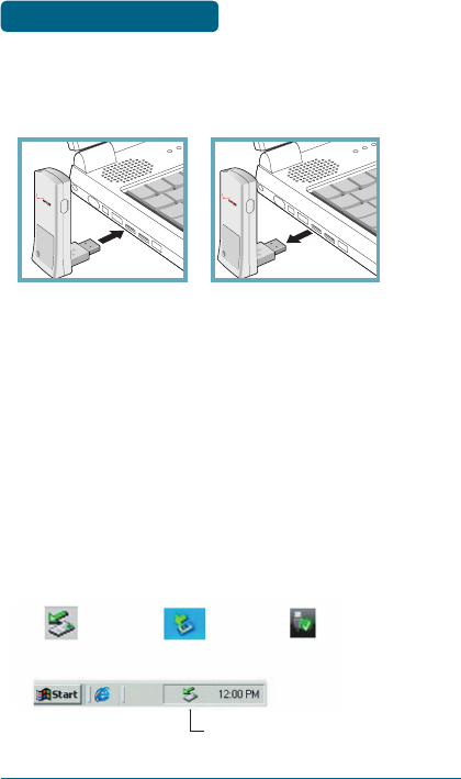
UNPLUGGING OR EJECTING THE DEVICE
Make sure to complete the unplug/eject process on your
computer before removing the UM175 from your PC. If you
remove the USB device improperly, the product may be
damaged.
•
WINDOWS
When disconnecting the UM175 from the computer, close
all windows and quit all running applications that are
stored on the device and double click the Unplug/Eject
Hardware icon in the System tray.
Windows 2000 Windows XP Vista
System Tray Unplug / Eject Hardware icon
INSTALLING UM175 UNPLUGGING OR
EJECTING THE DEVICE
11
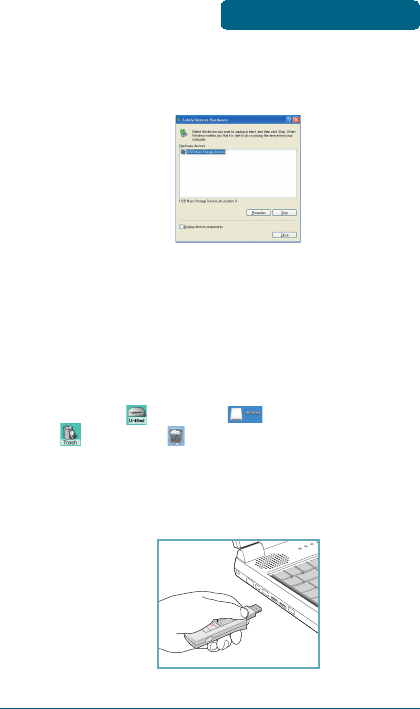
When you press the Unplug/Eject icon in the system tray, the
pop-up window will appear.
Click the [Stop] button. Now, you can remove the UM175
from your PC.
•
MACINTOSH
When disconnecting a USB mass device from the computer,
close all windows and quit all running applications that
are stored on the device and drag the device’s icon
(Mac OS9 – ; Mac OS X – ) onto trash (Mac OS9 –
; Mac OS 10 – ) to dismount it from the Desktop prior
to unplugging the device from the USB port or Hub.
@
When removing the UM175, always grip the top and bottom
of the modem and push/pull carefully.
INSTALLING UM175
UNPLUGGING OR
EJECTING THE DEVICE
12
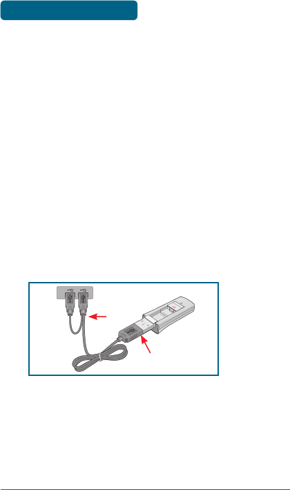
■
USB MODEM EXTENSION CABLE
The UM175 Modem package includes an extension USB
Y-shaped cable. Although the cable is not required for use
with your UM175 Modem, it offers increased performance
for your UM175 Modem under certain operating conditions.
Simply insert the USB connector into the USB port of your
computing device to deliver power boost, increased RF
performance, and to solve clearance issues.
USING THE USB MODEM EXTENSION CABLE:
1
Plug the single end of the Y-shaped cable into the
UM175 Modem. [A]
2
Depending on the condition you are trying to solve
(power boost, increased RF performance, or clearance
issues), plug either one of the two connected ends of
the USB modem extension cable into the Type A USB
port(s) on your computer. [B]
@
The USB modem extension cable connector labeled #1, is the
primary data power cable used to either extend the UM175
modem away from your computer allowing you to locate
the modem in a more optimum signal location or solve any
computer USB port clearance issues. The USB modem exten-
sion cable connector labeled #2, is a power boost cable and
must be used with connector #1 to provide the modem up to
1Amp of current for use in weaker signal areas.
A
B
#1
#2
INSTALLING UM175 USB MODEM
EXTENSION CABLE

13
3
The device is connected to and powered by the
computer as soon as the USB cable is plugged properly
into the appropriate Type A USB port(s).
4
Launch VZAccess Manager and click Connect.
INSTALLING UM175
USB MODEM
EXTENSION CABLE

14
MEMO
CHAPTER 3
REGULATORY
AND
SAFETY INFORMATION
REGULATORY NOTICES
OPERATING CONDITIONS
WARNINGS AND CAUTIONS
SAFETY PRECAUTIONS
16
■
REGULATORY NOTICES
UM175 complies with Parts 15, 22, and 24 of the FCC rules.
It has been tested with the typical personal computer
with a USB port. This USB device must not be co-located
or operated in conjunction with any other antenna
or transmitter. If you use this USB device in any other
configuration, the FCC RF Exposure compliance limit can be
exceeded.
■
OPERATING CONDITIONS
1
This device may not cause harmful interference, and this
device must accept any interference received, including
interference that may cause undesirable operations.
2
The manufacturer stipulates that the antenna should be
more than 1.5 cm (0.60”) from by-standers and 1.0cm
(0.39”) from the user.
REGULATORY NOTICES
REGULATORY AND SAFETY
INFORMATIONS

17
■
WARNINGS AND CAUTIONS
1
Modifying or changing this USB device without express
authorization can nullify compliance with RF exposure
guidelines.
2
This USB device has been tested and found to comply
with the limits pursuant to Part 15, 22, and 24 of the FCC
Rules. These limits are designed to provide reasonable
protection against harmful interference when
appropriately installed. This USB device generates, uses,
and can radiate radio frequency and, if not installed and
used according to the instructions provided, it may cause
harmful interference to radio communication. However,
there is no guarantee that interference will not occur in
any particular installation.
3
If this USB device does cause harmful interference with
radio or television signals (determine this by turning
the USB device off and on), attempt to correct the
interference by trying one or more of the following:
•
Reorient or relocate the antenna.
•
Increase the separation between the USB device and
receiver.
•
Connect the USB device into an outlet on a circuit
different from that to which the receiver is connected.
•
Consult the dealer or an experienced radio/TV
technician for help.
4
This USB device does not exceed the Class B limits for
radio noise emissions from digital apparatus as set out
in the interference causing equipment standard entitled
“Digital Apparatus”, ICES-003 of the Department of
Communications.
WARNINGS AND
CAUTIONS
REGULATORY AND SAFETY
INFORMATIONS

18
5
If you have purchased this product under a United States
Government contract, it shall be subject to restrictions
as set forth in subparagraph (C)(1)(ii) of Defense Federal
Acquisitions Regulations (DFARs) Section 252.227-7013
for Department of Defense contracts, and as set forth
in Federal Acquisitions Regulations (FARs) Section
52.227-19 for civilian agency contracts or any successor
regulations. If further government regulations apply,
it is your responsibility to ensure compliance with such
regulations.
* WARNING: This product contains a chemical known to the
State of California to cause cancer.
* WARNING: This product contains a chemical known to the
State of California to cause birth defects or
other reproductive harm.
REGULATORY AND SAFETY
INFORMATIONS
WARNINGS AND
CAUTIONS

19
■
SAFETY PRECAUTIONS
1
Data transmission and reception cannot be guaranteed
because of the nature of wireless communications. Data
can be delayed, corrupted or lost during transmission.
Even though it is quite rare that significant data delay
or loss occurs if the USB device is used in a normal
manner, this USB device should not be used in cases
that data transmission or reception failure could result
in damage of any kind to the user or another party,
including but not limited to personal injury, death or loss
of personal property. UTStarcom bears no responsibility
for damages or losses of any kind resulting from delays
or errors in data transmission using the USB device, or
for failure of the USB device to transmit or receive such
data.
2
Do not use this USB device in areas where blasting is in
progress, where explosive atmospheres may be present,
near medical equipment, life support equipment, or
any equipment which may be susceptible to any form
of radio interference. Turn off this USB device in these
areas, since it can transmit signals that could interfere
with this equipment.
3
Do not use this USB device in any aircraft whether the
aircraft is on the ground or in flight. Make sure to turn
off this USB device in aircraft.
If used in an aircraft, it can transmit signals that could
interfere with various aircraft systems.
4
Do not use this USB device while driving a car, since
it can distract driver’s driving. In some area, using the
communication device while driving a car is illegal.
REGULATORY AND SAFETY
INFORMATIONS
SAFETY PRECAUTIONS

20
MEMO

CHAPTER 4
APPENDIX
GLOSSARY
SPECIFIC ABSORPTION RATES (SAR)
SAFETY INFORMATION FOR RF
EXPOSURE

22
■
GLOSSARY
Analog Coverage
An area where analog service is available. Analog phones
usually indicate signal strength on an indicator in the
phone’s display when receiving an analog signal.
Browser
The software that allows you to view the Internet; contains
navigator commands such as forward and back; examples
include Netscape, Microsoft Explorer. A Web browser in your
computer requests HTML files from Web servers and takes
you to the Internet sites you wish to visit, by linking your
computer’s IP address to a site’s IP address.
COM PORT (communications port)
A connector for a communications interface, usually, a serial
port.
Data
Information kept in databases, on an intranet, on the
Internet, etc.
Driver
Software that controls a device.
Inactivity Time-Out
A stoppage in a connection, which usually occurs after a
period of time elapses, without activity. Time-out settings
are usually determined by the network.
APPENDIX GLOSSARY

23
Internet
A cooperatively run, globally distributed collection of
computer networks that exchange information via a
common set of rules for exchanging data (Transfer Control
Protocol/Internet Protocol or TCP/IP).
Intranet
An intranet is a web site created by a business, which
posts its own company information in a secure part of the
Internet that only employees or other authorized users can
reach. Intranets are generally protected by firewalls.
Kbps
Kilobits per second.
Kilobyte (KB)
1024 bits (Approximately 1/2 page of plain text)
Modem
Hardware that translates and transmits data over wire-line
or wireless.
Package Minutes
Package minutes are those minutes included in the cost of a
monthly service plan. Once the packaged minutes have been
exhausted, additional airtime charges apply. Please refer to
Plans and Pricing for more information, details and offers in
your area.
Packet Switching
Packet-switching messages are divided into packets or
pieces before transmission over one or more routes and are
reassembled at their destination.
APPENDIX
GLOSSARY

24
POP3 e-mail
Protocol used by ISP’s mail servers to manage e-mail for
subscribers. E-mail clients such as Microsoft Outlook support
POP3.
Proxy Settings
A specific I.P. address that allows access to a secured
enterprise network. The proxy settings provide directions
to a computer so that it can locate an address and access
information and services, which exist at that location.
Search Engine
A program that receives a user’s search request, compares
it to the entries in the index, and returns results to help the
user find relevant information.
Serial Port
A connector on a computer used to connect peripherals,
which communicate using a serial protocol.
Serial/Data Cable
A wire that connects two serial ports carrying data to one
another.
Transmission Speed
The rate at which data is sent over a communications line,
usually measured in kilobits (kbps).
USB Cable
A wire connecting two USB ports carrying data to one another.
USB Port
A connector on a computer to connect peripherals using
USB (Universal Serial Bus) protocol.
APPENDIX GLOSSARY

25
■
SPECIFIC ABSORPTION RATES (SAR)
Maximum: SAR 0.789 W/kg CDMA835 Body
SAR 0.904 W/kg PCS1900 Body
THIS MODEL PHONE MEETS THE GOVERNMENT’S
REQUIREMENTS FOR EXPOSURE TO RADIO WAVES.
Your wireless phone is a radio transmitter and receiver. It
is designed and manufactured not to exceed the emission
limits for exposure to radiofrequency (RF) energy set
by the Federal Communications Commission of the U.S.
Government. These limits are part of comprehensive
guidelines and establish permitted levels of RF energy
for the general population. The guidelines are based on
standards that were developed by independent scientific
organizations through periodic and thorough evaluation
of scientific studies. The standards include a substantial
safety margin designed to assure the safety of all persons,
regardless of age and health. The exposure standard for
wireless mobile phones employs a unit of measurement
known as the Specific Absorption Rate, or SAR. The SAR
limit set by the FCC is 1.6 W/kg. *
Tests for SAR are conducted with the phone transmitting
at its highest certified power level in all tested frequency
bands. Although the SAR is determined at the highest
certified power level, the actual SAR level of the phone
while operating can be well below the maximum value.
This is because the phone is designed to operate at multiple
power levels so as to use only the power required to reach
the network. In general, the closer you are to a wireless
base station antenna, the lower the power output. Before
a phone model is available for sale to the public, it must be
tested and certified to the FCC that it does not exceed the
APPENDIX
SPECIFIC ABSORPTION
RATES (SAR)

26
limit established by the government adopted requirement
for safe exposure. The tests are performed in positions
and locations (e.g., at the ear and worn on the body) as
required by the FCC for each model. The highest SAR value
for this model phone when tested for use at the when
worn on the body , as described in this user guide, is 0.904
W/Kg. (Body-worn measurements differ among phone
models, depending upon available accessories and FCC
requirements). While there may be differences between the
SAR levels of various phones and at various positions, they
all meet the government requirement for safe exposure.
The FCC has granted an Equipment Authorization for this
model phone with all reported SAR levels evaluated as
in compliance with the FCC RF exposure guidelines. SAR
information on this model phone is on file with the FCC
and can be found under the Display Grant section of
http://www.fcc.gov/ oet/fccid after searching on
FCC ID: PP4PX-700.
Additional information on Specific Absorption Rates (SAR)
can be found on the Cellular Telecommunications Industry
Asso-ciation (CTIA) web-site at http://www.wow-com.com.
* In the United States and Canada, the SAR limit for mobile
phones used by the public is 1.6 watts/kg (W/kg) averaged
over one gram of tissue. The standard incorporates a
sub-stantial margin of safety to give additional protection
for the public and to account for any variations in
measurements.
SPECIFIC ABSORPTION
RATES (SAR)
APPENDIX

27
■
SAFETY INFORMATION FOR RF EXPOSURE
BODY WORN OPERATION
This device was tested in multiple notebook computer
configurations with USB port configurations for typical
near-body operations with the back of the USB Modem
kept 20mm from the body. To maintain compliance
with FCC RF exposure requirements it can be used
in notebook computers with substantially similar
physical dimensions,construction, and electrical and
RF characteristics,and that maintain a minimum 20mm
separation distance between the user’s body and the back
of the USB Modem, including the antenna. The antenna(s)
used for this USB Modem must not be co-located or must
not operate in conjunction with any other antenna or
transmitter within a host device.
SAFETY INFORMATION
SAFETY INFORMATION FOR FIXED WIRELESS TERMINALS
POTENTIALLY EXPLOSIVE ATMOSPHERES
Turn your phone OFF when in any area with a potentially
explosive atmosphere and obey all signs and instructions.
Sparks in such areas could cause an explosion or fire
resulting in bodily injury or even death.
INTERFERENCE TO MEDICAL DIVICES
Certain electronic equipment may be shielded against RF
signal from you wireless phone. (pacemakers, Hearing Aids,
and so on) Turn your phone OFF in health c are facilities
when any regulations posted in these areas instruct you
to do so. RF signals may affect improperly installed or
inadequately shielded electronic system in motor vehicles.
SAFETY INFORMATION
FOR RF EXPOSURE APPENDIX

28
EXPOSURE TO RF ENERGY
Use only the supplied or an approved replacement antenna.
Do not touch the antenna unnecessarily when the phone is
in use. Do not move the antenna close to, or couching any
exposed part of the body when making a call.
FCC COMPLIANCE INFORMATION
This device complies with Part 15 of FCC Rules.
Operation is subject to the following two conditions:
(1) This device may not cause harmful interference, and
(2) This device must accept any interference received.
Including interference that may cause undesired
operation.
SAFETY INFORMATION
FOR RF EXPOSURE
APPENDIX