ParTech M8935 Temperature Measuring Device User Manual
ParTech Inc. Temperature Measuring Device
ParTech >
User Manual

7/11/2011
Behavioral Description v1.14 | Scott Leapman
P
ARTECH
E
VER
S
ERV
S
URE
C
HECK
TMD
UX

2
Contents
Document Revision Log.................................................................................................................... 3
Abstract................................................................................................................................................ 4
Overall Design Methodology...........................................................................................................4
Navigation ........................................................................................................................................... 5
TMD Screen...................................................................................................................................... 5
TMD Buttons ..................................................................................................................................... 6
Sure Check PDA Temperature Observation Dialog................................................................7
Temperature Measurement Workflow ........................................................................................... 8
Temperature Measurement Workflow Overview.....................................................................8
Measuring Temperatures with the Probe ................................................................................ 10
Measuring Temperatures with the IR Sensor ........................................................................... 13
Measuring Temperatures with the RFID Sensor....................................................................... 16
Temperature RFID Tag ................................................................................................................... 16
TurboTag RFID Tag......................................................................................................................... 19
Timer UI Workflow.............................................................................................................................. 22
Using the Stopwatch.......................................................................................................................... 23
Using the Countdown Timer .............................................................................................................. 24
Bluetooth UI Workflow ..................................................................................................................... 25
Bluetooth Status ............................................................................................................................ 25
Bluetooth Radio Control ............................................................................................................. 25
Battery UI ............................................................................................................................................ 28
Battery Status................................................................................................................................. 28
Battery Charging .......................................................................................................................... 29
Power States...................................................................................................................................... 30

3
Document Revision Log
Version Date Description
1.00 06/29/2011 Initial Draft.
1.10 07/08/2011 Expanded scope of document to include overall
UX for the TMD. Renamed to a “UX” document.
1.11 07/09/2011 Updated the RFID temperature measurement
workflows per team review.
1.12 07/11/2011 Reverted the TurboTag RFID workflow.
1.13 07/11/2011 Added the Charging UX workflow.
1.14 07/11/2011 Added the Bluetooth Radio UX workflow.

4
Abstract
This document describes the overall user experience (UX) design of the Temperature
Measurement Device (TMD). Included are workflows for measuring temperatures with
the TMD when used in conjunction with a PDA running the EverServ Sure Check PDA
software. Workflows are listed for capturing temperatures with the TMD in each of its
three (3) measurement modes. Examples are provided with functional descriptions.
Not all screens are illustrated or described in this document; however, the visual design
may be applied across the entire product.
Note that all screenshots are provided as examples and are not intended to be used as
the exact UI to emulate in the real product as-is.
The Visual Design Guide document describes the overall design of the product whereas
this document delves deeper into each section of the applicable UI and how it should
function for the user. The companion Behavioral Description document for the
Configuration UI and PDA UI describes similarly the function and design of the web-
based configuration interface that works in tandem with the PDA interface.
Overall Design Methodology
Where applicable, the following governing principles are used in the design of the UI:
1. The visual design of this application UI must be consistent with other applications
in the EverServ suite; EverServ Enterprise Configuration Management, EverServ
QSR & TSR Editions, EverServ Operations Manager, etc.
2. Optimization for the majority of defined workflows.
3. All UI controls are intended for finger access and should not require the use of a
stylus.
4. Color, size, shape and position are used to group controls with similar functions.
5. Attention is guided to the primary controls in any given UI by virtue of that
control’s placement, color or size.
6. Visual simplicity and use of whitespace to minimize UI clutter.
7. Eliminate left/right scrolling and minimize up/down scrolling.
5
Navigation
The following sections outline the rationale, and where applicable, functional details,
for each section of the user interface (UI) of the TMD.
All of the following screens presume that the PDA has been loaded with the
appropriate checklists for the location where it is registered per the companion Server
(configuration) UI.
It is unknown as to what audio feedback, if any, is available on the TMD. If possible,
audio feedback should be defined for events such as but not limited to; measurement
scan started, stable reading available, unstable or manual reading available, error,
measurement validation is not OK and measurement validation is OK.
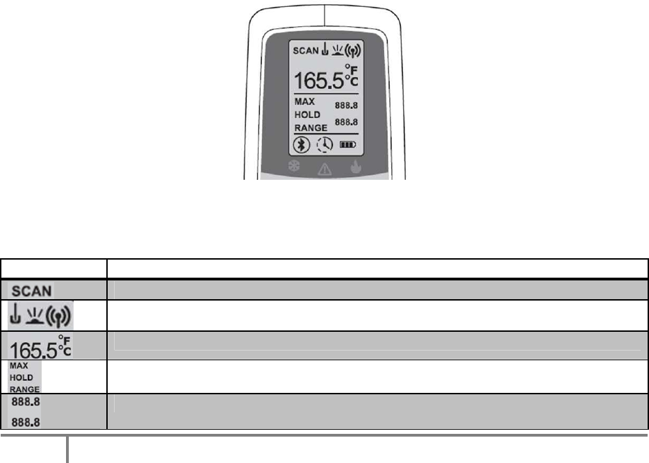
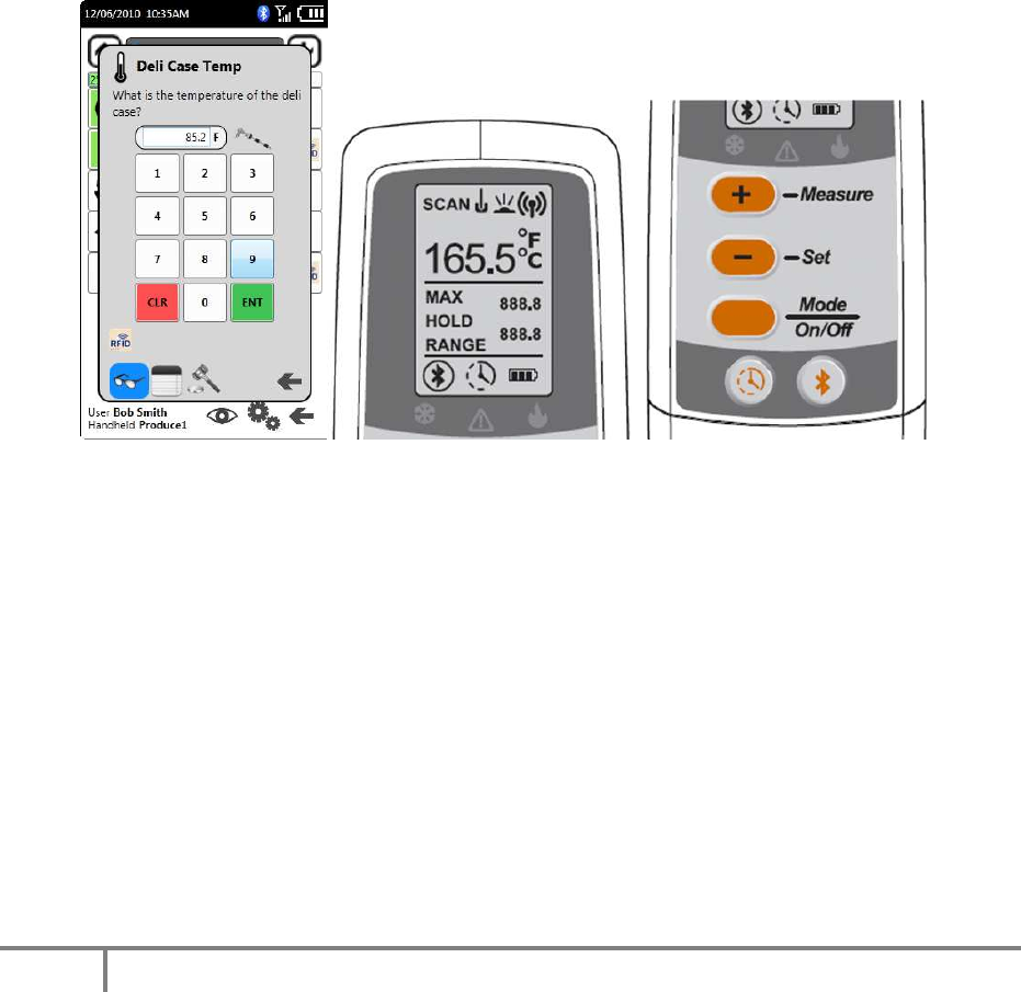
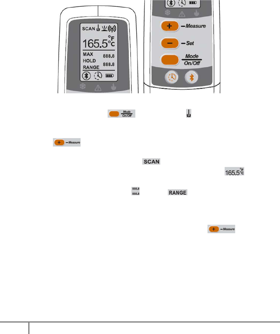
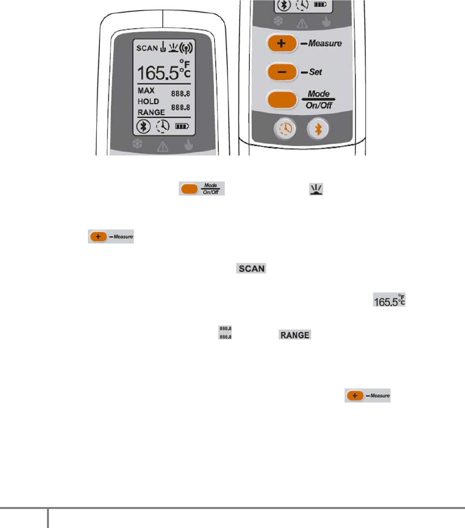
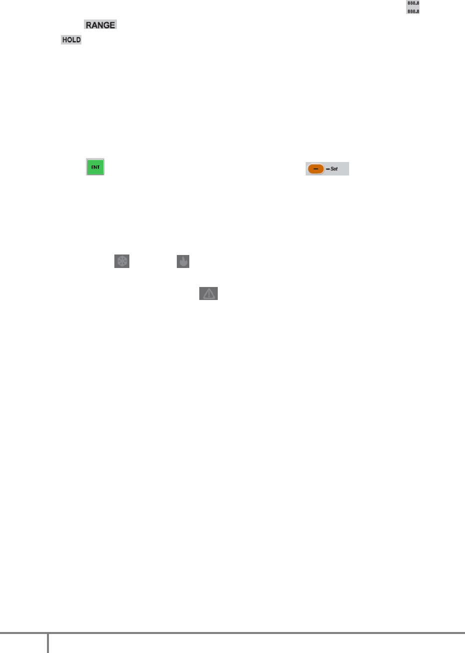
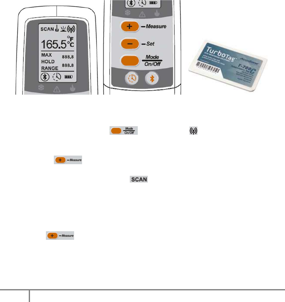
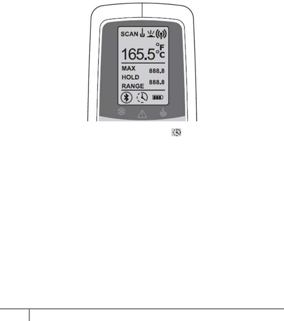
TMD Screen
The screen consists of the follow UI elements as LCD segments that are lit according to
conditions outlined in the sections that follow:
Element Description/Use
Indicates that a temperature measurement is in-progress.
Indicates the temperature sensing mode; probe, IR or RFID.
Indicates the current or final temperature and the units.
Labels for the two range values.
Indicates the range of values for the measured temperature.
6
Indicates the status of the Bluetooth connection to the PDA.
Indicates that the timer mode is set and running.
Indicates the charge level of the built-in battery.
HACCP LED Indicators for Cold (green), Alert (red) and Hot (green).
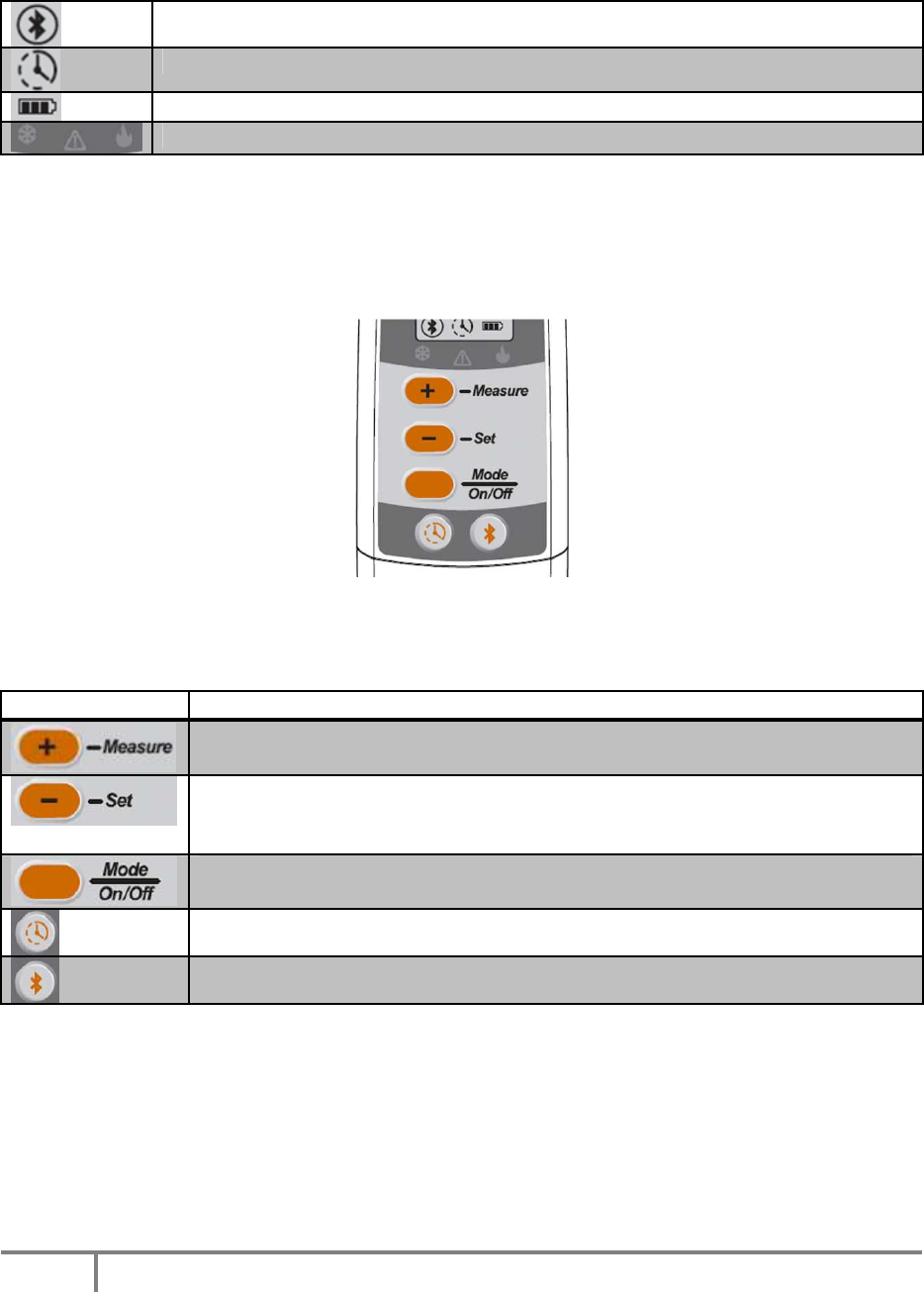
TMD Buttons
The physical buttons on the TMD control its operation and interact with a connected
PDA over the Bluetooth connection as outlined in the sections that follow:
Element Description/Use
Initiates a measurement using the selected sensing mode.
Increments the counter when in Timer mode.
Changes the display units (F vs C). Sends an “ENT” command via BT.
Decrements the counter when in Timer mode. Note: Should be
relabeled as “OK/Units”
Changes the sensing mode between probe, IR and RFID. Turns the
TMD on or off. Note: Should be relabeled as “Mode/Power”
Switches to Timer mode. Starts or stops the timer.
Turns the Bluetooth radio on or off and enters Pairing mode.
7
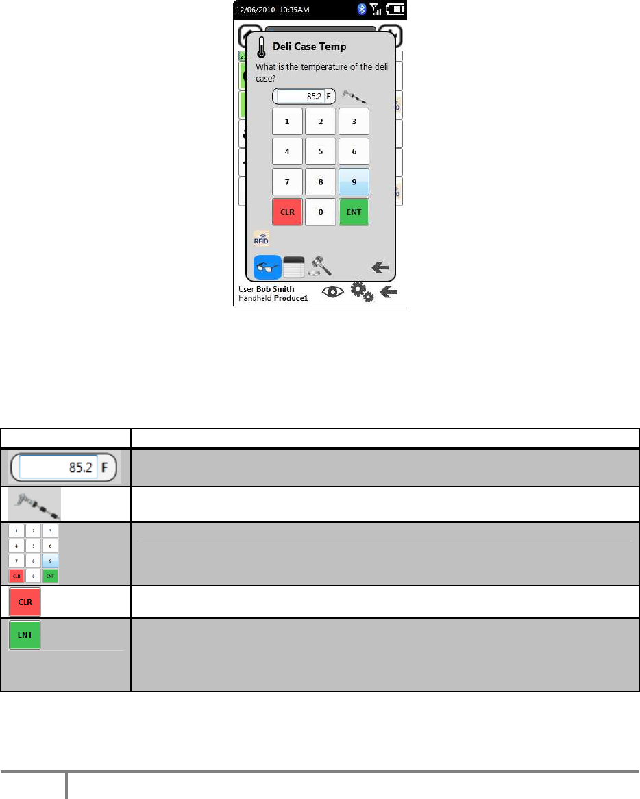
Sure Check PDA Temperature Observation Dialog
The above is a sample Observation Dialog from the prototype Sure Check PDA
software for a temperature-type measurement check item. Certain screen elements
are used in conjunction with the TMD when sensing a temperature for a check
observation as outlined in the following sections:
Element Description/Use
Displays the current temperature measurement as either typed or
transmitted from the TMD via BT.
Indicates that a TMD is paired and available for use.
Number pad used to manually enter values (if enabled).
Button used to clear the value in the temperature display.
Button used to accept the value in the temperature display and
validate it against the check violation rules. Note that the TMD “Set”
button performs the same function as described in the following
sections.
8
Temperature Measurement Workflow
During the use of the Sure Check PDA software, a user may be required to observe a
temperature-type measurement check. The sections that follow describe the
interaction between the User, the Sure Check PDA software and the TMD device.
Temperature Measurement Workflow Overview
A sample Observation Dialog is shown above. This dialog expects the user to provide a
temperature value for a checklist item. The user would either type in a value (manual
entry) or would use a TMD to measure and supply the value to the PDA via a Bluetooth
(BT) connection.
When using the RFID sensing mode, the PDA software may also be on the list of checks
screen (Checklist contents) and the RFID workflow may be used as a shortcut without
first having the check’s respective Observation Dialog open.
To use the TMD to measure the temperature, the user would select the desired
measurement mode with the Mode button and then start a measurement scan with
the Measure button. Once measured, the current temperature will update on both the
TMD screen and the PDA’s Observation Dialog.

9
Regardless of the method used to supply the value to the Observation Dialog, the value
will not be processed for violation until it has been validated by the user. The user may
either press the ENT button on the PDA screen or press the Set/Units button on the TMD
to do so. Once either condition has occurred, the value is validated against the rules
set in the Configuration UI.
If the value is acceptable, the Observation Dialog is dismissed, the HACCP “OK” icons
on the TMD are illuminated, and the Sure Check PDA software continues as outlined in
its BD document. If the value is in violation, a Corrective Action Dialog is shown on the
PDA screen and the HACCP “Alert” icon on the TMD is illuminated.
10
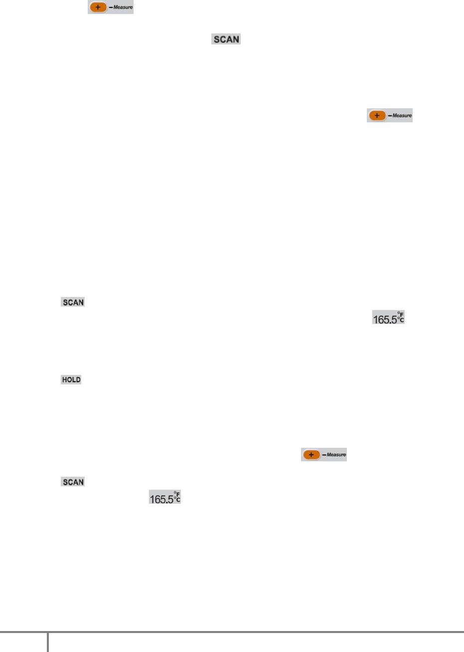
Measuring Temperatures with the Probe
For this workflow, the user will measure the temperature of an item with the built-in
temperature probe in the TMD. The PDA must be displaying the respective check
item’s Observation Dialog.
Measurement
1. With the TMD on, press the button until the icon illuminates to indicate
the Temperature Probe sensing mode.
2. The upper value display and lower value displays should be clear (no value).
3. Press the button to start a measurement session. If any HACCP icons
were illuminated from a prior measurement session, they are cleared.
4. A measurement session is started and flashes.
5. The current measurement value is shown in the top-most display .
6. The maximum and minimum values for all measurements thus far in this session
are displayed in the range display and the label is also illuminated.
7. Measurement samples continue (return to step 4 above) until one of the
following conditions occurs:
a. Stable: 5 consecutive measurements are within 0.5F of each other.
b. Aborted: User terminates measurement by pressing before a
stable temperature is measured or the session times out.
c. Timed-Out: The session times out after 30 seconds of measurements
without a stable temperature.
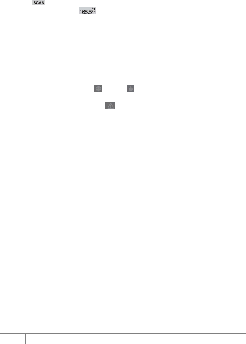
Once a measurement session has ended, the following occurs depending on how the
session ended:
Stable
11
This measurement session ends as soon as the measurement is considered stable. Ex: if
temperatures are sampled at a rate of 1 per second and the temperature is stable, this
measurement session will automatically end after 5 seconds (5 samples).
• The label is turned off.
• The stable measurement value is shown in the top-most display and is sent
to the PDA for display in the Observation Dialog.
• The maximum and minimum values for the entire session are displayed along
with the label and are sent to the PDA.
• The label is displayed to indicate a stable measurement.
Aborted
This measurement session ends as soon as the user presses the button;
regardless of the temperature value.
• The label is turned off.
• The most recent measurement value is shown in the top-most display and
is sent to the PDA for display in the Observation Dialog.
• The maximum and minimum values for the entire session are displayed along
with the label and are sent to the PDA.
• The label flashes to indicate that the measurement wasn’t stable.
Timed-Out
This measurement session ends after the maximum session time has elapsed; regardless
of the temperature value. This is a safe-guard to prevent against the TMD remaining in
a sensing mode indefinitely and thus draining the battery.
• The label is turned off.
• The most recent measurement value is shown in the top-most display and
is sent to the PDA for display in the Observation Dialog.
• The maximum and minimum values for the entire session are displayed along
with the label and are sent to the PDA.
• The label flashes to indicate that the measurement wasn’t stable.
Validation
Regardless of the means by which the scanning session ended, the value will not be
processed for violation by the PDA until it has been validated by the user. The user may

12
either press the button on the PDA screen or press the button on the TMD
to do so. Once either condition has occurred, the value is validated against the rules
set in the Configuration UI.
• Not a Violation: If the value is acceptable, the Observation Dialog is dismissed
and the Sure Check PDA software continues as outlined in its BD document.
Both the Cold and Hot icons on the TMD are illuminated.
• Violation: If the value is in violation, a Corrective Action Dialog is shown on the
PDA screen and the Alert icon on the TMD is illuminated.
Notes:
• The TMD will transmit all values as if they were typed on a Bluetooth keyboard.
Therefore, the PDA must properly accept and process the values transmitted by
the TMD.
• The rules for determining a stable measurement are used as an example and are
configurable.
• The maximum duration of a scanning session is used as an example and is
configurable.
• The sampling rate of measurements is used as an example and is configurable.
• It is suggested that algorithms be devised to prevent the TMD from inadvertently
and automatically stabilizing on ambient (room) temperature before the probe is
inserted in the item to be measured.
13
Measuring Temperatures with the IR Sensor
For this workflow, the user will measure the temperature of an item with the built-in IR
sensor in the TMD. The PDA must be displaying the respective check item’s Observation
Dialog.
Measurement
1. With the TMD on, press the button until the icon illuminates to
indicate the IR sensing mode.
2. The upper value display and lower value displays should be clear (no value).
3. Press the button to start a measurement session. If any HACCP icons
were illuminated from a prior measurement session, they are cleared.
4. A measurement session is started and flashes.
5. The IR targeting LED illuminates on the front of the TMD to assist in aiming.
6. The current measurement value is shown in the top-most display .
7. The maximum and minimum values for all measurements thus far in this session
are displayed in the range display and the label is also illuminated.
8. Measurement samples continue (return to step 4 above) until one of the
following conditions occurs:
a. Stable: 5 consecutive measurements are within 0.5F of each other.
b. Aborted: User terminates measurement by pressing before a
stable temperature is measured or the session times out.
c. Timed-Out: The session times out after 30 seconds of measurements
without a stable temperature.
Once a measurement session has ended, the following occurs depending on how the
session ended:
14
Stable
This measurement session ends as soon as the measurement is considered stable. Ex: if
temperatures are sampled at a rate of 1 per second and the temperature is stable, this
measurement session will automatically end after 5 seconds (5 samples).
• The label is turned off.
• The IR targeting LED on the front of the TMD turns off.
• The stable measurement value is shown in the top-most display and is sent
to the PDA for display in the Observation Dialog.
• The maximum and minimum values for the entire session are displayed along
with the label and are sent to the PDA.
• The label is displayed to indicate a stable measurement.
Aborted
This measurement session ends as soon as the user presses the button;
regardless of the temperature value.
• The label is turned off.
• The IR targeting LED on the front of the TMD turns off.
• The most recent measurement value is shown in the top-most display and
is sent to the PDA for display in the Observation Dialog.
• The maximum and minimum values for the entire session are displayed along
with the label and are sent to the PDA.
• The label flashes to indicate that the measurement wasn’t stable.
Timed-Out
This measurement session ends after the maximum session time has elapsed; regardless
of the temperature value. This is a safe-guard to prevent against the TMD remaining in
a sensing mode indefinitely and thus draining the battery.
• The label is turned off.
• The IR targeting LED on the front of the TMD turns off.
• The most recent measurement value is shown in the top-most display and
is sent to the PDA for display in the Observation Dialog.
15
• The maximum and minimum values for the entire session are displayed along
with the label and are sent to the PDA.
• The label flashes to indicate that the measurement wasn’t stable.
Validation
Regardless of the means by which the scanning session ended, the value will not be
processed for violation by the PDA until it has been validated by the user. The user may
either press the button on the PDA screen or press the button on the TMD
to do so. Once either condition has occurred, the value is validated against the rules
set in the Configuration UI.
• Not a Violation: If the value is acceptable, the Observation Dialog is dismissed
and the Sure Check PDA software continues as outlined in its BD document.
Both the Cold and Hot icons on the TMD are illuminated.
• Violation: If the value is in violation, a Corrective Action Dialog is shown on the
PDA screen and the Alert icon on the TMD is illuminated.
Notes:
• The TMD will transmit all values as if they were typed on a Bluetooth keyboard.
Therefore, the PDA must properly accept and process the values transmitted by
the TMD.
• The rules for determining a stable measurement are used as an example and are
configurable.
• The maximum duration of a scanning session is used as an example and is
configurable.
• The sampling rate of measurements is used as an example and is configurable.
• It is suggested that algorithms be devised to prevent the TMD from inadvertently
and automatically stabilizing on ambient (room) temperature before the IR
sensor is properly aimed at the item to be measured.
16
Measuring Temperatures with the RFID Sensor
For this workflow, the user will measure the temperature of an item with the built-in RFID
scanner in the TMD. The PDA may be displaying the respective check item’s
Observation Dialog or it may be displaying the list of check items (Checklist contents)
screen. For full details, see the “RFID Tag Workflow” section in the “EverServ Sure Check
v2 PDA Behavioral Description” document.
There are several varieties of RFID temperature tags available and the workflow varies
for each.
Temperature RFID Tag
This type of RFID temperature tag senses the current temperature but does not store
historical data. When requested by the TMD, this tag will send the current temperature
value as a single data point as well as the tag’s unique ID. This tag is not parsed for a
“stable” reading – only the most current reading as of the scanning session is used.
Measurement
1. With the TMD on, press the button until the icon illuminates to
indicate the RFID sensing mode.
2. The upper value display and lower value displays should be clear (no value).
17
3. Press the button to start a scanning session. If any HACCP icons were
illuminated from a prior measurement session, they are cleared.
4. A scanning session is started and flashes.
5. The TMD searches for a suitable RFID tag that has temperature sensing capability.
The search continues until one of the following conditions occurs:
a. Suitable Tag Found: A temperature-sensing tag has been found (non-
TurboTag).
b. Aborted: User terminates scanning for a tag by pressing before
a suitable tag has been found and before the session times out.
c. Timed-Out: The session times out after 30 seconds of searching without a
suitable tag being found.
Once a scanning session has ended, the following occurs depending on how the
session ended:
Suitable Tag Found
This scanning session ends as soon as a suitable RFID tag has been found.
• The label is turned off.
• The current measurement value is shown in the top-most display and is
sent to the PDA for display in the Observation Dialog along with the tag’s unique
ID.
• The maximum and minimum value displays remain blank.
• The label is displayed to indicate a stable measurement.
Aborted
This scanning session ends as soon as the user presses the button.
• The label is turned off.
• The top-most display remains blank. No data is transmitted to the PDA.
• The maximum and minimum value displays remain blank.
Timed-Out
This scanning session ends after the maximum session time has elapsed. This is a safe-
guard to prevent against the TMD remaining in a sensing mode indefinitely and thus
draining the battery.
18
• The label is turned off.
• The top-most display remains blank. No data is transmitted to the PDA.
• The maximum and minimum value displays remain blank.
Validation
The PDA will compare the transmitted temperature and unique ID values against the
check item per the values set in the Configuration UI.
• Not a Violation: If the value is acceptable, the Observation Dialog is dismissed (if
it was open) and the Sure Check PDA software continues as outlined in its BD
document. Both the Cold and Hot icons on the TMD are illuminated.
• Violation: If the value is in violation, a Corrective Action Dialog is shown on the
PDA screen and the Alert icon on the TMD is illuminated.
Notes:
• For full details of how RFID tag sensing is used with the Sure Check PDA software,
see the “RFID Tag Workflow” section in the “EverServ Sure Check v2 PDA
Behavioral Description” document.
• The TMD will transmit all values as if they were typed on a Bluetooth keyboard.
Therefore, the PDA must properly accept and process the values transmitted by
the TMD.
• The maximum duration of a scanning session is used as an example and is
configurable.
19
TurboTag RFID Tag
This type of RFID temperature tag senses the current temperature and stores up to 702
historical data points in built-in memory in the tag. When requested by the TMD, this tag
will send all data points to the TMD including the tag’s unique ID. This tag’s historical
data is parsed for a “stable” reading in addition to being sent to the PDA for processing.
Measurement
1. With the TMD on, press the button until the icon illuminates to
indicate the RFID sensing mode.
2. The upper value display and lower value displays should be clear (no value).
3. Press the button to start a scanning session. If any HACCP icons were
illuminated from a prior measurement session, they are cleared.
4. A scanning session is started and flashes.
5. The TMD searches for a suitable RFID tag that has temperature sensing capability.
6. The process continues until one of the following occurs:
a. Suitable Tag Found: All historical data is transmitted from the tag to the
TMD.
b. Aborted: User terminates scanning for a TurboTag RFID tag by pressing
before a suitable RFID tag is found and before the session times
out.
c. Timed-Out: The session times out after 30 seconds of searching for a
suitable RFID tag.
20
Once a scanning session has ended, the following occurs depending on how the
session ended:
Suitable Tag Found
This scanning session ends as soon as a suitable RFID tag is found.
• The label is turned off.
• Starting with the most current temperature value, the TMD will step backwards in
time through the historical data received from the tag for up to 50 data points.
Each step backward will compare the prior consecutive 5 values for a stable
reading.
• Once 5 consecutive measurements are within 0.5F of each other, the
temperature is considered stable and that value is shown in the top-most display
and is sent to the PDA along with the tag’s unique ID and all historical
data.
• The maximum and minimum values for the entire session (up to 50 data points)
are displayed along with the label and are sent to the PDA.
• The label is displayed to indicate a stable measurement.
Aborted
Scanning for a TurboTag RFID tag ends as soon as the user presses the button.
If a TurboTag was found before the user aborts the session, then the session cannot be
aborted and pressing the button will start a new RFID scanning session.
• The label is turned off.
• The upper value display and lower value displays should be clear (no value)
since no tag was found.
Timed-Out
Scanning for a TurboTag RFID tag ends after the maximum session time has elapsed
and no tag was found. This is a safe-guard to prevent against the TMD remaining in a
sensing mode indefinitely and thus draining the battery.
• The label is turned off.
• The upper value display and lower value displays should be clear (no value)
since no tag was found.

21
Validation
The PDA will compare the transmitted temperature and unique ID values against the
check item per the values set in the Configuration UI.
• Not a Violation: If the value is acceptable, the Observation Dialog is dismissed (if
open) and the Sure Check PDA software continues as outlined in its BD
document. Both the Cold and Hot icons on the TMD are illuminated.
• Violation: If the value is in violation, a Corrective Action Dialog is shown on the
PDA screen and the Alert icon on the TMD is illuminated.
Notes:
• For full details of how RFID tag sensing is used with the Sure Check PDA software,
see the “RFID Tag Workflow” section in the “EverServ Sure Check v2 PDA
Behavioral Description” document.
• Once a TurboTag RFID tag has been found, the TMD will transmit the pertinent
values as if they were typed on a Bluetooth keyboard. Therefore, the PDA must
properly accept and process the values transmitted by the TMD.
• The maximum duration of a scanning session is used as an example and is
configurable.
22
Timer UI Workflow
The TMD has a built-in timer that can either count up from zero (stopwatch) or count
down time from a user-specified value.
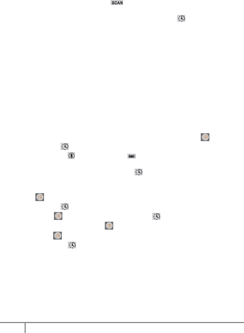
If a timer (count down or count up) is in-progress, the icon blinks. This applies to all
timer and measurement modes.
When in the timer mode, the upper (large) display is not used and should remain blank.
The middle display is used to count minutes from 0-999 and the lower display is used to
count seconds from 00.0 to 59.9.
Ex:
1. The middle display starts at 000 and the lower display starts at 00.0
2. The lower display counts from 00.0 seconds to 59.9 seconds. Then it resets to 00.0
and the middle display increments to 1 to represent 1 minute.
3. The current time is read by combining the integer value in minutes from the
middle display and the decimal value in seconds from the lower display.
a. Ex: 23 in the middle display and 34.3 in the lower display equals 23:34.3 or
23 minutes and 34.3 seconds.
4. Once the middle display reaches 999 minutes and the lower display reaches 59.9
seconds, the stopwatch function stops and remains at that value.
Notes:
23
• Either timer mode can be viewed or initiated when the TMD is not actively
measuring a temperature; when is not displayed.
• If a timer is in-progress, a temperature measurement may be started and the
timer will continue to run in the background. The blinking icon indicates that
a timer is still running in the background.
• An in-progress timer is ended when the TMD enters the Off power state but can
continue to run when in all other power states. The TMD will provide an audio
alert before automatically entering the Off power state and thus canceling any
active timer.
Using the Stopwatch
The stopwatch function starts at zero and counts elapsed time in minutes and seconds
until the user stops the function. The stopwatch is capable of counting elapsed time up
to 16 hours, 39 minutes and 59.9 seconds.
1. With the TMD on and not actively measuring a temperature, press .
2. The timer icon is displayed and all other display elements are cleared except
for the Bluetooth and battery status icons which remain.
a. If a timer is currently in-progress (count up or count down), its current
value is shown while the timer icon blinks. Continue with step 4.
b. If a timer is not currently in-progress, the display show their initial values as
outlined above.
3. Press to start the stopwatch.
4. The timer icon blinks and the displays update. No units are shown.
a. Press to stop the timer. The timer icon stops blinking. If the timer has
been stopped, pressing again resumes the timer.
b. Hold for 2 seconds to clear the timer, reset the displays and stop the
timer icon from blinking, if applicable.
24
Using the Countdown Timer
The countdown timer function starts at a user-specified value and counts down to zero.
When the counter reaches zero (0), the timer stops and the TMD beeps (tbd). The
countdown timer is capable of being set in whole minute increments from 1-999.
1. With the TMD on and not actively measuring a temperature, press .
2. The timer icon is displayed and all other display elements are cleared except
for the Bluetooth and battery status icons which remain.
a. If a timer is currently in-progress (count up or count down), its current
value is shown while the timer icon blinks. Continue with step 5.
b. If a timer is not currently in-progress, the display show their initial values as
outlined above.
3. Press or to set the middle display to the desired count down start time in
minutes from 1 to 999.
a. If either or is held for more than 2 seconds, the middle display
increments (or decrements) in five (5) minute increments until released.
b. If is held for 2 seconds, any set time is cleared.
4. Press to start the count down from the set value.
5. The timer icon blinks and the displays update. No units are shown.
a. Press to stop the current timer. The timer icon stops blinking. If the
timer has been stopped, pressing again resumes the timer.
b. Hold for 2 seconds to clear the timer, reset the displays and stop the
timer icon from blinking, if applicable.
25
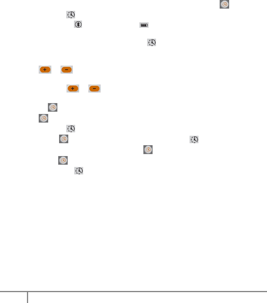
Bluetooth UI Workflow
The status of the TMD’s built-in Bluetooth radio can be determined by the state of the
Bluetooth status icon. The Bluetooth radio’s state can be controlled via the Bluetooth
button.
Bluetooth Status
The Bluetooth icon indicates the radio’s connectivity and power state per the following
table.
Icon State Description
(none) Off BT radio is off.
On BT radio is on but not connected.
Connected BT radio is on and connected but not actively
communicating.
(blinking)
Pairing BT radio is on and not connected and is available for
pairing requests.
(blinking
ring)
Communicating
BT radio is on, connected and actively
communicating.
Bluetooth Radio Control

26
The Bluetooth radio’s various states can be controlled with the BT button per the
following table.

27
Current State Action Final State
Any except Off Hold for 2 seconds Off
Off Hold for 2 seconds On
Any except Pairing,
Communicating
Hold for 5 seconds Pairing
Pairing Hold for 5 seconds Prior state (aborts Pairing)
Notes:
•
If the BT radio is already connected and the user requests the Pairing mode, the
current connection is broken in favor of finding a new connection.
•
The TMD will automatically exit Pairing mode if no suitable connection is made
within 60 seconds. It will then revert to the prior mode and be available to
reconnect to the last-paired device.
•
If the TMD enters the Off power state, the state of the Bluetooth radio is retained
(except for Pairing mode) and resumed once the TMD enters any other power
state.
28
•
Battery UI
The status of the TMD’s built-in rechargeable battery can be determined by the state of
the battery status icon. The battery can be charged by either a Micro USB cable or a
drop-in charger. Either method follows the same workflow outlined below.
Battery Status
Regardless of the operational mode and for all power states except for “Off,”the
battery status icon will reflect the real-time estimated power level per the following
table.
Battery Icon State Power Level
High 70-100%
Medium 40-69%
Low 10-39%
(outline
blinking)
Critical <10%
The TMD will automatically enter the “Off” power state approximately 5 minutes after
reaching the Critical battery state. At that time, any current operation is aborted.
29
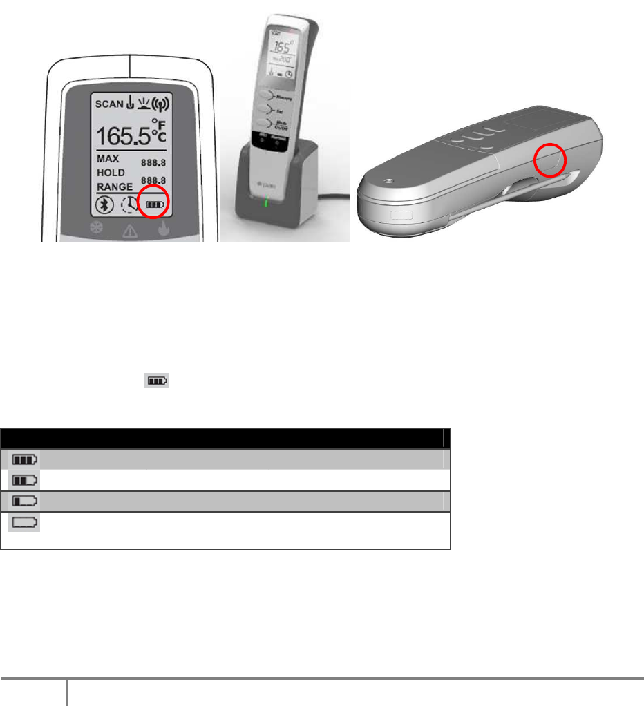
Battery Charging
The TMD will start charging the battery when it is connected to a suitable power source;
either the drop-in charger or a Micro USB cable. During the charging process, the
battery icon will indicate the current charge level as outlined in the following table.
For all of the following states, the outline of the battery icon is solid.
Battery Icon State Power Level
(all 3 internal segments solid)
Full 100%
(all 3 internal segments blinking)
High 70-99%
(2 internal segments blinking)
Medium 40-69%
(1 internal segment blinking)
Low 1-39%
Notes:
• If the TMD is in the “Off” state when connected to a suitable power source, the
unit will immediately enter the “Sleep” power state for the duration of the
charging process. The battery will charge and the icon will indicate the
charging state, but the device will otherwise remain in the “Sleep” power state.
• Once charging is complete, the device will remain in its current power state until
disconnected from a power source or another suitable trigger changes the
power state.
• A “Full” battery will trickle charge to maintain that power level until the power
source is disconnected.
• Disconnecting the TMD from a power source will immediately set the TMD to the
“Active” power state regardless of the battery level or the prior power state.
30
Power States
The TMD has many components that consume battery power. In order to conserve the
built-in rechargeable battery, power states have been defined as per the following
table.
State Description
Active TMD is actively being used; a measurement scan is in-process, a button has
been pressed, etc.
Idle TMD is not actively being used but is in a state such that it can be used
immediately upon request. BT may be connected but data is not being
transmitted or received.
Sleep TMD is able to accept connections via BT or USB but otherwise is not being
used. BT radio is on but not connected.
Off TMD is using the minimal amount of power and must be activated via the
power button in order to be used.
The chart below outlines the various major subsystems of the TMD and whether they are
on and consuming power for each of the above defined power states.
Component States:
Active
Idle
Sleep
Off
Backlight Yes
Temperature
Probe
Yes
1
Yes
1
IR Sensor Yes
1
Yes
1
RFID Sensor Yes
1
Yes
1
LCD Screen Yes Yes Yes
2
Bluetooth Radio Yes Yes Yes
USB Port Yes Yes Yes
MCU Yes Yes Yes Yes
3
Notes:
1. Only the last-selected sensor is on in this state. All other sensors are off regardless
of state.
2. Backlight is off and only the Bluetooth icon and the battery icon are
visible.
3. MCU is in a low-power state (standby) only to enable the Power On/Off button.
31
The chart below illustrates the cadence and timing of power states and how the user’s
interaction with the TMD affects the entry and exit of each state.
Notes:
1. Button press returns the TMD to “Active” and initiates the function respective to
the button pressed.
2. Button press returns the TMD to “Active” but does not initiate the function
respective to the button pressed. The button must be pressed again after the
TMD returns to the “Active” state.
3. Fifteen (15) seconds before automatically transitioning from the Sleep to Off
states, the device will emit a sound (tbd).
Federal Communication Commission Interference Statement
Press Power
button for 2
seconds.
Press any
button or a
BT
connection
is initiated.
2
Press any
button.
1
Press Power
button for 5
seconds.

32
This device complies with Part 15 of the FCC Rules. Operation is subject to the following two
conditions: (1) This device may not cause harmful interference, and (2) this device must accept
any interference received, including interference that may cause undesired operation.
This equipment has been tested and found to comply with the limits for a Class B digital device,
pursuant to Part 15 of the FCC Rules. These limits are designed to provide reasonable
protection against harmful interference in a residential installation. This equipment generates,
uses and can radiate radio frequency energy and, if not installed and used in accordance with
the instructions, may cause harmful interference to radio communications. However, there is
no guarantee that interference will not occur in a particular installation. If this equipment does
cause harmful interference to radio or television reception, which can be determined by turning
the equipment off and on, the user is encouraged to try to correct the interference by one of
the following measures:
- Reorient or relocate the receiving antenna.
- Increase the separation between the equipment and receiver.
- Connect the equipment into an outlet on a circuit different from that
to which the receiver is connected.
- Consult the dealer or an experienced radio/TV technician for help.
FCC Caution: Any changes or modifications not expressly approved by the party responsible for
compliance could void the user's authority to operate this equipment.
This transmitter must not be co-located or operating in conjunction with any other antenna or
transmitter.