Parabody 940101 Assembly Instruction
940101 to the manual 75d2c777-7881-43b0-8129-6ff12d799419
2014-12-13
: Parabody Parabody-940101-Assembly-Instruction-125533 parabody-940101-assembly-instruction-125533 parabody pdf
Open the PDF directly: View PDF ![]() .
.
Page Count: 4
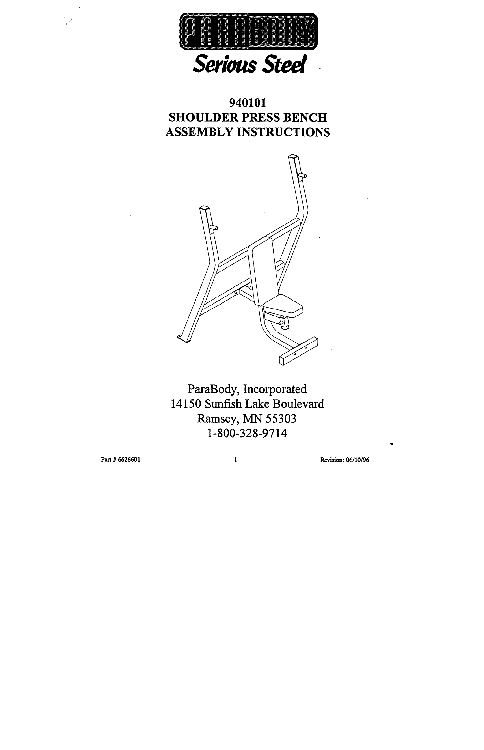
Serious Steel
940101
SHOULDER PRESS BENCH
ASSEMBLY INSTRUCTIONS
ParaBody, Incorporated
14150 Sunfish Lake Boulevard
Ramsey, MN 55303
1-800-328-9714
Part # 6626601 1 Revision: 06110196
940101 SHOULDER PRESS BENCH ASSEMBLY INSTRUCTIONS
ill I I
~::~:~;~;~;~;~:.:-:.~ ...............
:: ::::::::::::::::::::::::::::::::::::::....:.,..~.;...,::~ .:.~......~..~...;,.::~.~.....:.....,.,:..... ................~:~...~.;...~:~:~.....-.:.-.-.-.;.- ..............:...,-.....~.,:,:.~:.:..:~::: ~~::::.:.::~;~::.:~:::::: ............
:::::::::::::::::::::::::::::::::::::::::::::::::::::::: :::::::::::::::::::::::::::::::::::::::::::::::::::::::::::::::::::::::::::::::::::::::::::::::::::::::::::::::::::::::::::::::::::::::::::::::::::::::::::::::::: :::::::::::::::::::::::::::::::::::::::::::::::::::::::::::::::::::::::::::::::::::::::::::::::::::::::::::::::::::::
::~:‘~:‘~::::::::::>:~:~:~::~::~::.:~::::~::::~:~>~>>>:~:~:.>>:.>>:::~>:.>>:~::.>:~:~.:.:.::~>. ..:--...:....... .:::., .~, -,... ..:
, :,~::.:~:.~:~.:~::.:~. ~::. ~: ~. ~. ~::~::~::~::::~ :~:.~::::~::~:-~::: ~:::::-~:-::~: ~ .............. ~.:.~ .:.~ ~ .~,::~::~,~::::~:~::~ ~.:.:~.:~~
:::.:~::~-.’." ........ :::~..~::.~.:~:~..~.~...~:::~.~.~.:....:~.~....~..:~...:.:.......~.~.~.~...~....~...~.~..~...~.......~.~..~..~.~.~. .:~.......~.~.~.~.~.....~:.~......:::::.~:~....~.+~:..~.~+~.....~.~<...~.~"~...~[~..~:~. :~:.~:~>~>.~>:.>::~:~>~>:~:.~:.:.~:.:.~>:.:.::~:.:.:.~:~::~>~::~:~::::~.
:~::::s:::::::: ...................... .:: ¯ ¯ ......
~~ ........... ~....:.:...:(:~.:~.:,:~.~:::.:: :.:..~,:~::::::::: ~::::::~::~
............. ........
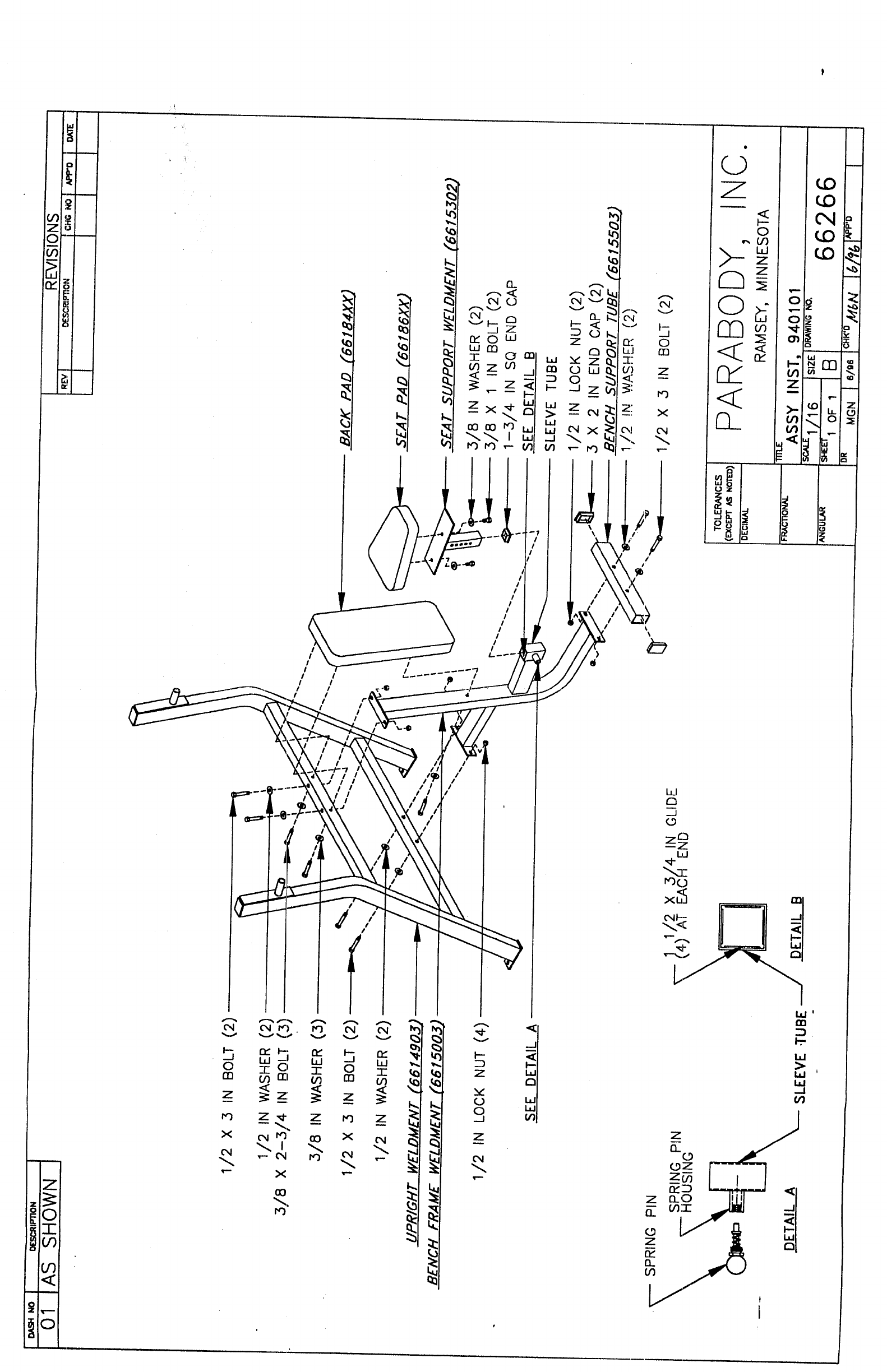
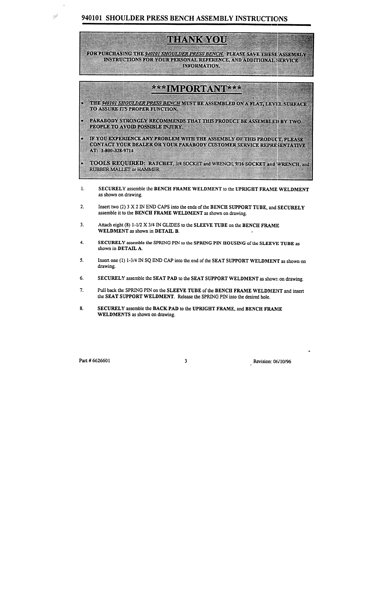
SECURELY assemble the BENCH FRAME WELDMENT to the UPRIGHT FRAME WELDMENT
as shown on drawing.
Insert two (2.) 3 X 2 IN END CAPS into the ends of the BENCH SUPPORT TUBE, and SECURELY
assemble it to the BENCH FRAME WELDMENT as shown on drawing.
Attach eight (8) 1-I/2 X 3/4 IN GLIDES to the SLEEVE TUBE on the BENCH FRA~ME
WELDMENT as shown in DETAIL B.
SECUREL~’ assemble the SPRING PIN to the SPRING PIN HOUSING of the SLEEV’E TUBE as
shown in DETAIL A.
Insert one (1) 1-3/4 IN SQ END CAP into the end of the SEAT SUPPORT WELDMENT as shown
drawing.
6. SECURELY assemble the SEAT PAD to the SEAT SUPPORT WELDMENT as showr, t on drawing.
Pull back the: SPRING PIN on the SLEEVE TUBE of the BENCH FRAME WELDMENT and insert
the SEAT SI[JPPORT WELDMENT. Release the SPRING PIN into the desired hole.
SECURELY assemble the BACK PAD to the UPRIGHT FRAME, and BENCH FRAME
WELDMEI~ITS as shown on drawing.
Part # 6626601 3Revision: 0(;/I0/96
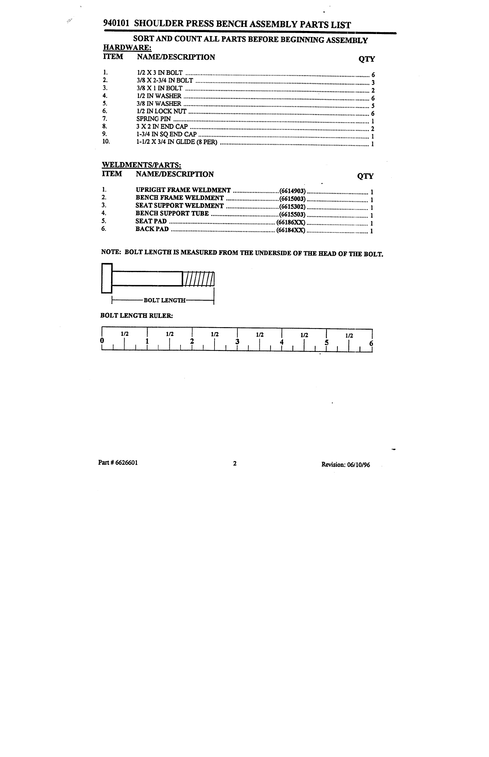
940101 SHOULDER PRESS BENCH ASSEMBLY PARTS LIST
SORT ~D COUNT/kLL P.~RTS BEFOliE BEGINNING ASSEMI|LY
HARDWARE:
ITEM
2.
3.
4.
5.
6.
7.
8.
9.
NAM]UDESCRIPTION QTY
1/2 X 3 IN BOLT ............................................................................................................... 6
3/8 X 2-,3/4 IN BOLT .......................................................................................................... 3
3/8 X 1 IN BOLT ................................................................................................................ 2
I/2 IN WASHER
3/8 IN WASHER ................................................................................................................. 5
1/2 IN LOCK Nlfr
SPRING PIN
3 X 2 IN END CAP ............................................................................................................ 2
1o3/4 IN SO END CAP ....................................................................................................... 1
l-l/2 X 3/4 IN GLIDE (~ PER) .......................................................................................... l
WELDMENTS~’ARTS:
ITEM NAM~7DESCRIPTION QTY
2.
3.
4.
5.
6.
UPRIGHT FRAME WELDMENT ............................ (6614903) ..................................... 1
BENCH FRAME WELDMENT ................................ (6615003) ..................................... 1
SEAT SUPPORT WELDMENT ................................ (6615302) ..................................... 1
BENCH SUPPORT TUBE ......................................... (6615503) ................... ~ .................1
SEAT PAD ................................................................ (66186XX) ..................................... 1
BACK PAD ............................................................... (66184XX) ...................................... 1
NOTE: BOLT LENGTH IS MEASURED FROM THE UNDERSIDE OF THE. HEAD OF TII~ BOI,T.
i!!!!!!!i
BOLT LENGTH !
BOLT LENGTH RULER:
] 1/2 1/2 I 1/2 I 1/2 I 1/2 I 1/2 I
2 3 4 5 6
Part # 6626601 2Revision: 06/10/96
