Parabody Leg Press Factor 625 Assembly Instruction
Factor 625 to the manual 60a63b70-3999-4c75-bd3c-2731067a02ad
2014-12-13
: Parabody Parabody-Leg-Press-Factor-625-Assembly-Instruction-125605 parabody-leg-press-factor-625-assembly-instruction-125605 parabody pdf
Open the PDF directly: View PDF ![]() .
.
Page Count: 10
9/t~ inch wrench ~ odiustable wrench
inch wrench ¯ hammer or rubber mallet
inch wrench ¯ s~2 allen wrench
¯ THE PARABODY FACTOR 625 BASE UNIT MUST BE ASSEMBLED ON A FLAT, LEVEL SURFACE TO ASSURE ITS PROPER FUNC1
¯ PARABODY STRONGLY RECOMMENDS THAT THIS PRODUCT BE ASSEMBLED BY TWO PERSONS TO AVOID POSSIBLE INJURY.
,, KEEP ALL FRAME BOLT CONNECTIONS LOOSE UNTIL INSTRUCTED IN THE ASSEMBLY STEP SEQUENCES TO SECURELY TIGHTi
MAKE SURE SNAP HOOKS ARE FASTENED BEFORE DOING EXERCISES.
NOTE:We recommend cleaning your produd (pads and the frame members
PoraBody Customer Service Representative at 1-800-328-9714.
on a regular basis, using worm soapy water. Also, touch-up paint can be purchnsed from your
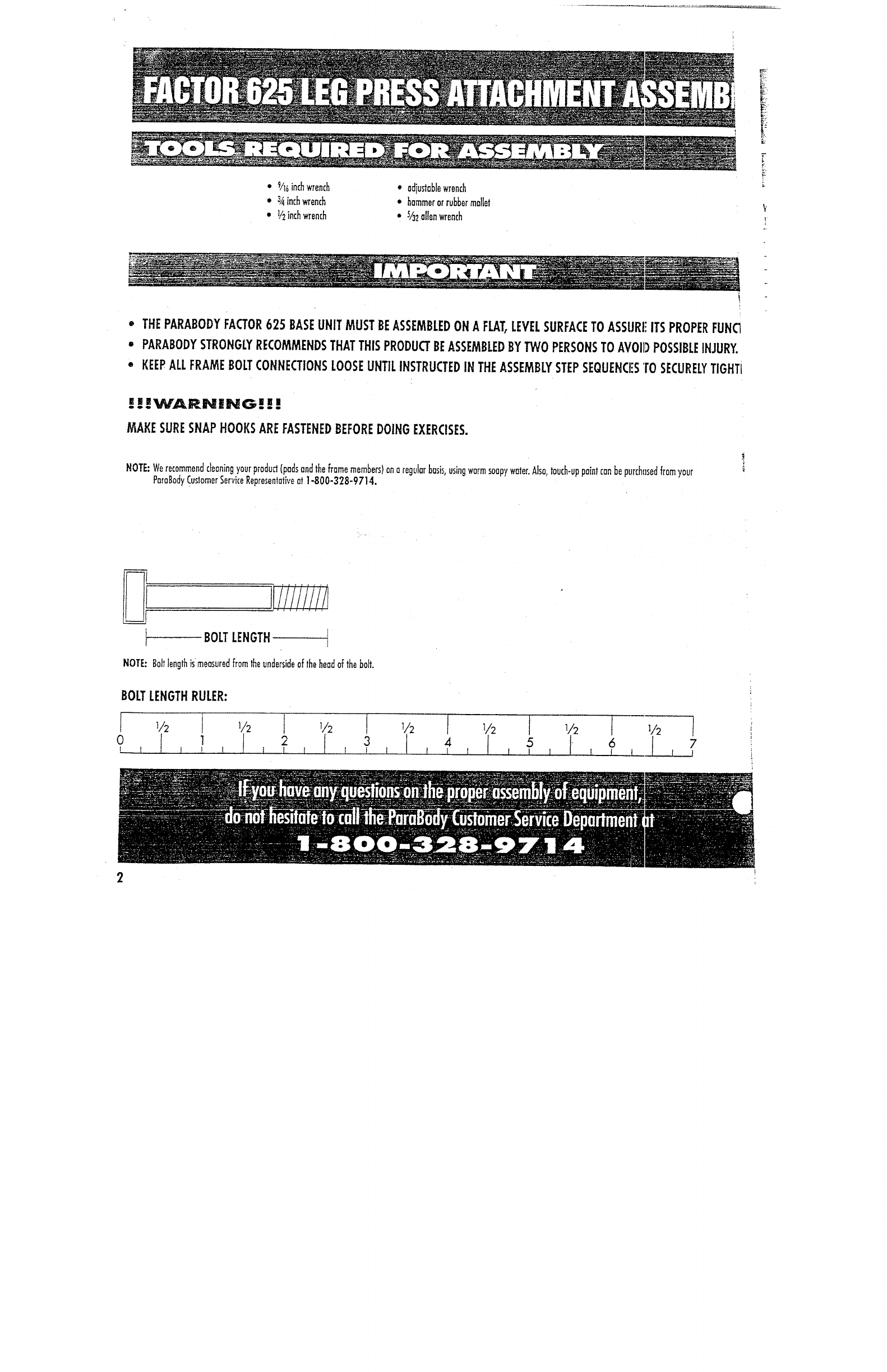
BOLT LENGTH
NOTE: Bolt length ismensured from the underside of the head of the bolt.
BOLT LENGTH RULER:
TTS/PARTS: OTY.
NAME/DESCRIPTION
~~(P~78-011 1
Back Pod ~--~B0-01 ) 1
Leg Press Frame ~PB3170-01) 1
Telescoping Tube Plated ~"-’~43-01) l
~~- -- (PB3047-01) 1
Pivot Axle __ [PB3OBI-01) 1
(PB3236-01) l
Leg Press Cable 17
’~
~634-01) 4
Non-Skid Strip 4" x
count all parts before beginning assembly.
’ARE: NAME/DESCRIPTION QTY.
-’Gr---’-~p I I/4
"
x S" 2
~/4" x I" Oilite Bushing -- I
~Compressi.___~on Spr~ l
Co~e~ Pin l
P~unger
Spacer
Knob
~" Square E.nd_ Cop (I 0-I 4 ga)~
Weight Stock Bumper
3/B" x l lh
’’ Bol~ ’t
-~e" Washer
~osher
~ Washer
~Pulley
3/~" x 4~/~
" Bol~
1
l
l
5
7
2
2
4
1
3
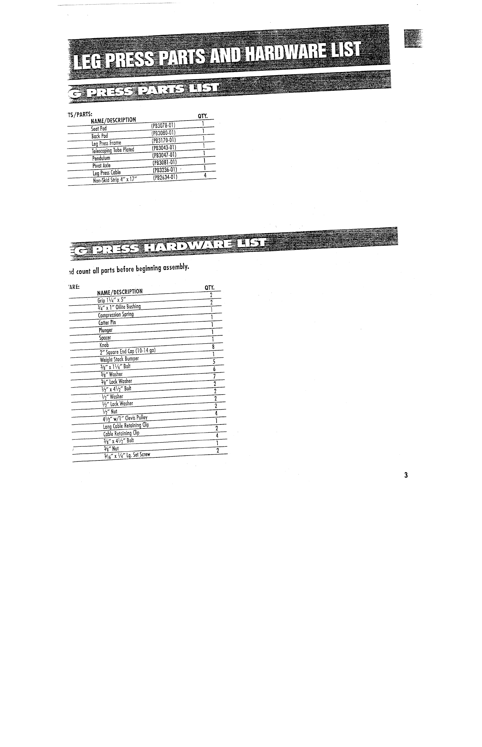
If you have installed a second weight stack, go to
Figure 5.
If you have not purchased the second weight
stack, please camp]ere the folJowing steps before
proceeding to F~gure 5.
1.Remove the blank shroud from the rear of the
Factor 625.
2. Remove the rotary cable from the unit and
also the assadated shock cord.
3. Load the Leg Press Cable into the
D-Ring in the position the Rotary Cable was
removed from. Remove the elastic shock cord
from the Rotary Cable and attach to the Leg
Press Cable as shown (same routing of elastic
cord as on Rotary Cable).
ELASTIC SHOCK CORD
LEG PRESS CABLE
(PB3236-01)
-- D:RING
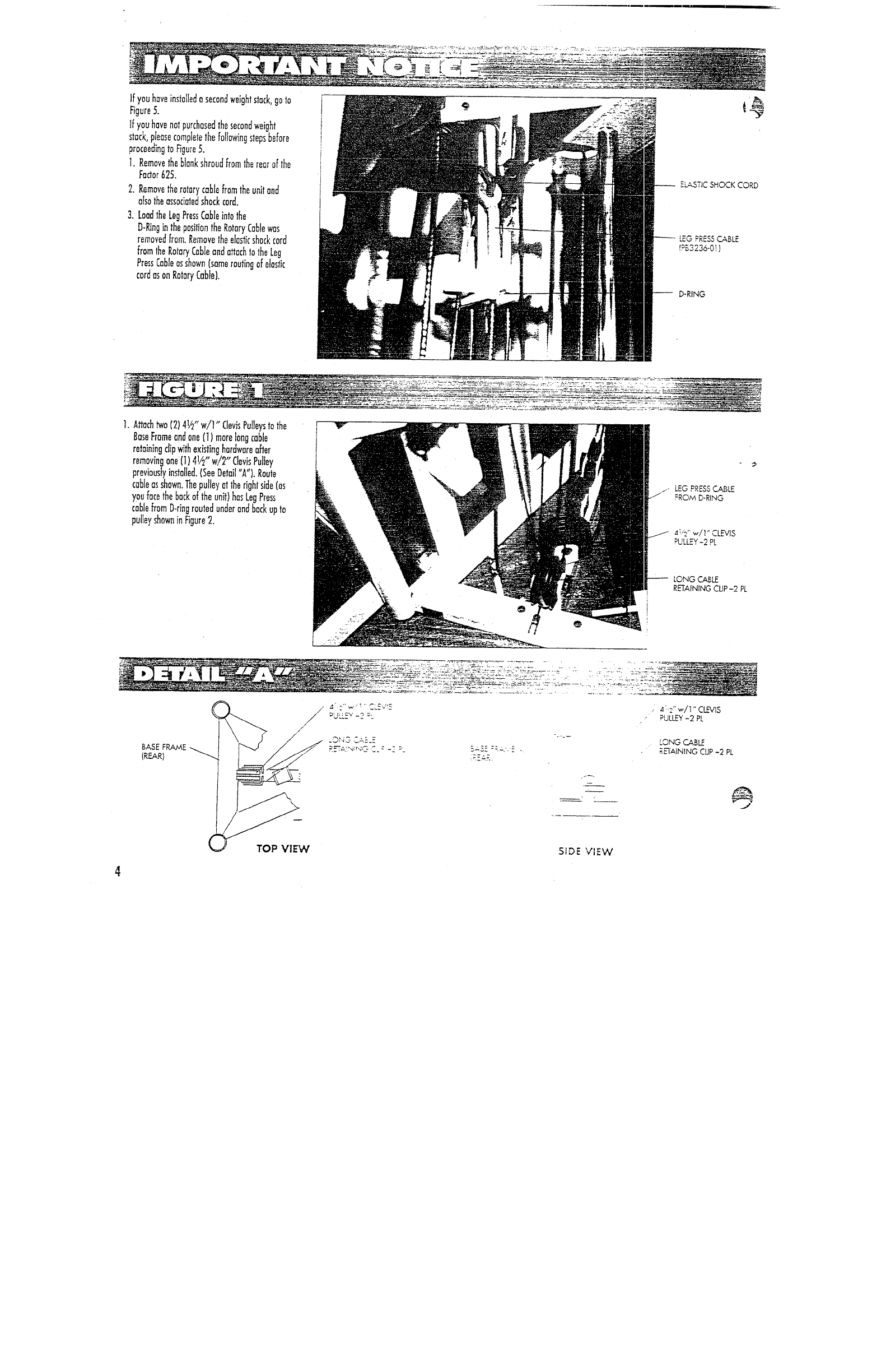
1. Attach two (2) 4V2 w/l Clev;s Pulleys to the t’~ ’--:~ ~ --~’-
Base Frame and one {I) mare long cable
retaining clip with existing hardware after
removing one (1) 41/2" w/2" Clevis Pulley
previously installed. (See Detail "A"). Route ~
cable as shown. The pulley at the right side (as ~k~. LEG PRESS C.ABLE
you face the back of the unit) has Leg Press FRO,~ D-RING
cable from D-ring routed under and back up to
pulley shown in Figure 2.
PULLEY-2 PL
LONG
R~AINING CUP-2 PL
. PULL~ -2 PL
SIDE VIEW
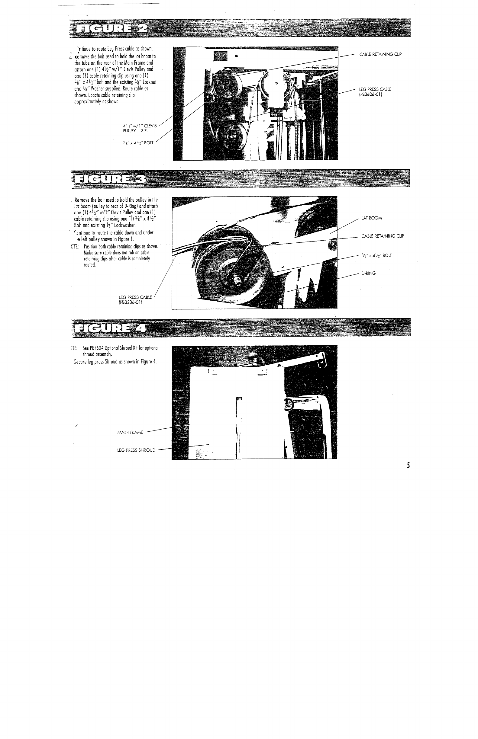
~tinue to route Leg Press cable as shown.
,. ,~emave the boll used to hold the la~ boom 1o
~’he tube an the rear of" lhe Main Frame and
~aih one I1) 4~.,~" w/l" Clevis Pulley and
one (1) cable retaining clip using one (t)
~-~" x 4(.’~’" bolt and the existing 34" Locknu~
and 34" Washer supplied. Raule cable as
shown. Locme ~able retaining clip
approxim~ety as shown.
CA.BL~ RETAINING CLIP
LEG PRESS CA,BLE
(PB3626-01)
,4: 2" w/1 " CLL-VIS
PULLEY- 2 PL
.. Remove the bolt used to hold the pulley in the
!m boom (pulley to rear of D-Ring} and attach
one (1) 4!.~" w/l" Clevis Pulley and one (1)
cable retaining clip using one (I) 3/if’ x 4V~"
Ba]t and existing :ks" Lockwasher.
~"antinue to route the cable dawn and under
e left pulley shown in Figure 1.
iO~ Position both cable retaining clips as shown.
Make sure cable does hal rub on cable
retaining clips after cable is completely
routed.
LEG PRESS CABLE ’ !
(PB3236-01) L
LAT BOOM
CABLE RETAINING CLIP
D-RING
)TL See PBF604 Optional Shroud Kit for optional
shroud ~sembly.
Secure leg press Shroud as shown in Figure 4.
~G PRESS SHROUD
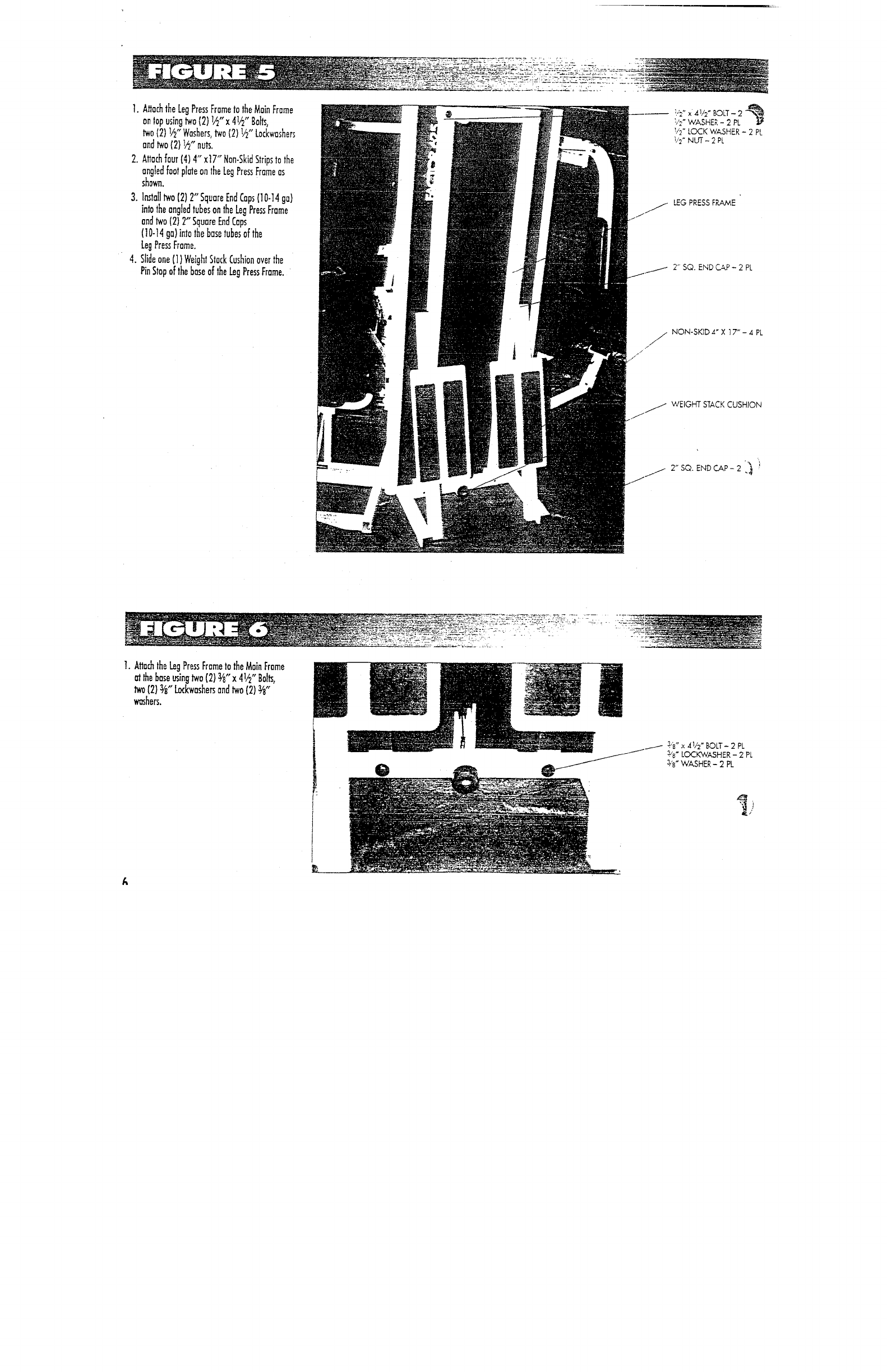
1.AHach the Leg Press Frame to the Main Frame
on lop using two {2) l~"x 41~" Bolts,
two (2) 1/2" Washers, two (2) I/2" Lockwashers
and two (2) 1,~,, nuts.
2.Attach four (4) 4" x17" Non-Skid Strips to the
angled foot pl~e on the Leg Press Frame as
shown.
3. Install two (2) 2" Square End Caps {10-14 ga)
into the angled tubes on the Leg Press Frame
and two (2) 2" Square End Caps
(10-14 ga)into the base tubes of the
Leg Press Frame.
4. Slide one (1) Weight Stock Cushion over the
Pin Stop of the base of the Leg Press Frame.
---~ V:’x4V2"BOLT-2 ~
b"2
~ WASHER - 2 PL
b~" LOCK WASHER - 2 PL
~,,’2" NUT - 2 PL
2" SQ. END CAP - 2 PL
jNON-SKID ,~" X 17" - 4 PL
WEIGHT STACK CUSHION
2" SQ. END CAP-2 ~"~
1.Attach the Leg Press Frame to the Main Frame
al lhe base using two (2) ~’8" x 41~" Bolts,
two (2} ~" ~kwasher~ and two (2)
~hers.
~" LOCKWASHER - 2 PL
SPACER
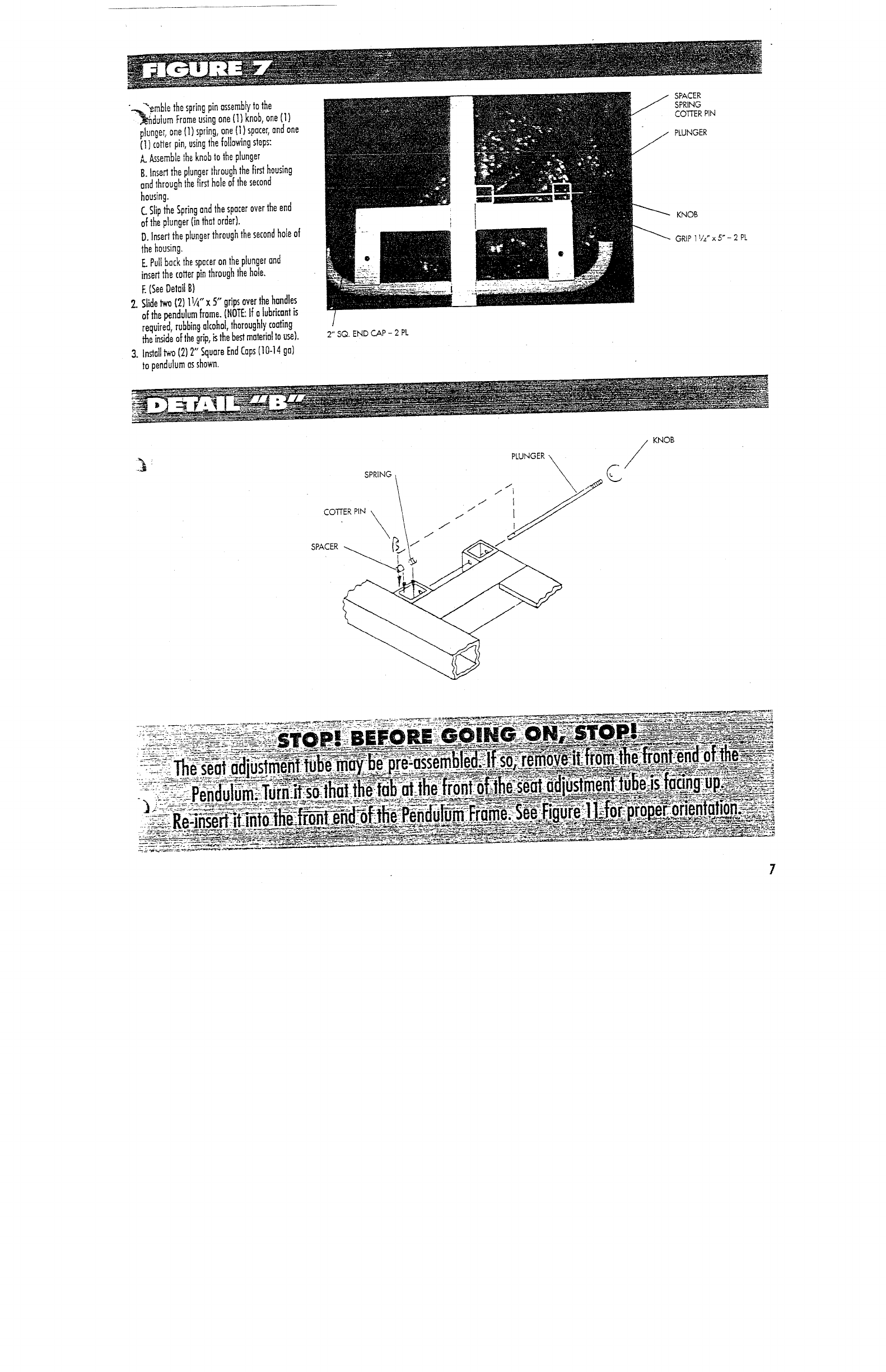
".--~~ble the spring pin assemblT to the SPR~NG
~autum Frame using one (1) knob, one (I) co~ P~N
plunger, one (1) spring, one (1) spacer, and ~kUNG~
(1) co~e~ pin, using the folJowing steps:
~ ~semble the knob to the p~ungsr
B. In~d the plunger through the fi~ housing
and through the fir~ hole of the second
housing.
C Slip ~e Spring and the spacer over the end ~~
of the plunger (in that order). ~os
D. Insed the plunger through the second hole of G~ ~ ~" x 5
~-
2 ~k
the housing.
E PulJ back the spacer on the plunger and
inse~ the co~er pin through the hole.
E (See 0etail B)
~ Slide ~ (2} 1~/4" x 5" grips over the handles
of ~e ~ndulum flame. (NOTE: If a ~ubricant is
requ red, rubbing alcohol thoroughly coating
~e i~de of the grip, ~ ~e b~ material to u~). 2" SQ. END ~P - 2 PL
3. In~lJ ~ (2) 2" Square End Caps (10-14
to pendulum as shown.
SPRING ~ PLUNGER
KNOB
C
7
If]
Fig
If’
1.
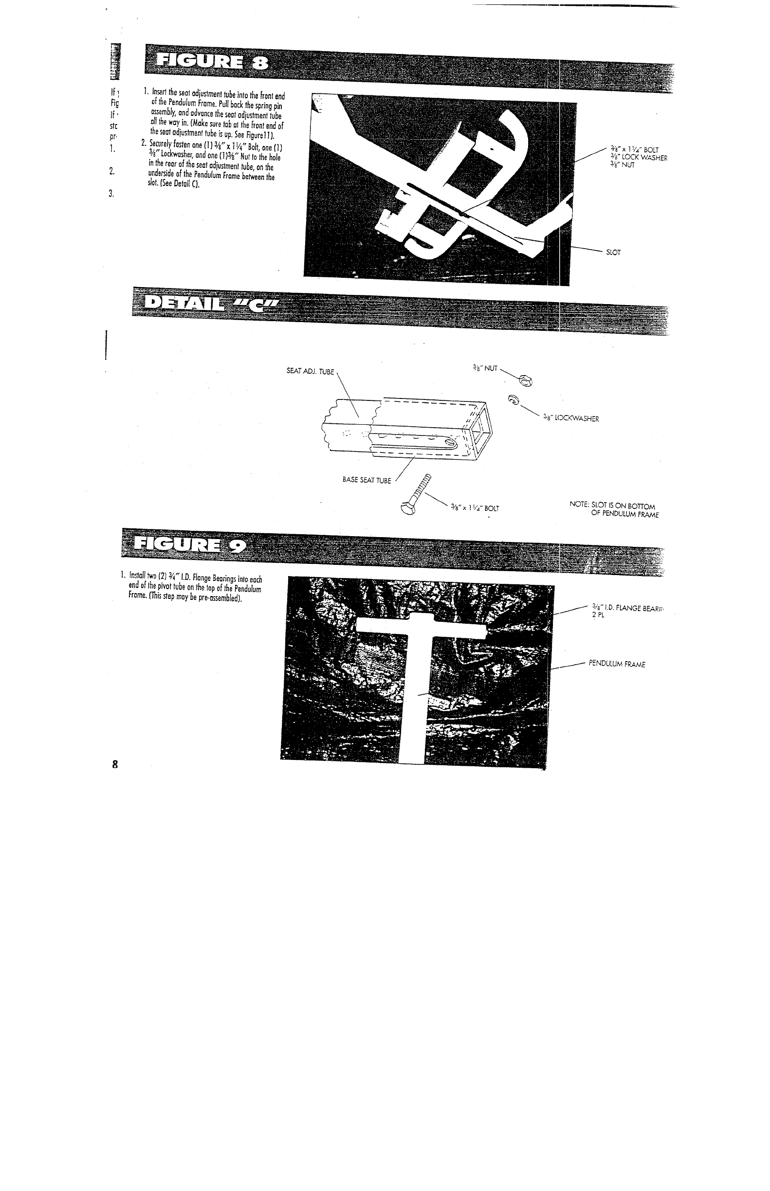
nser~ the seat adjustment tube Into the front end
of the Pendulum flame. Pull back the spring pin
a~mb/y, and advance the seat adjustment tube
al1 the way in. (Make sure tab ai the front end of
the seat adiustment tube is up. See figure] I).
2..Securely fasten one fl) 3~,’ x 1 ]/4" Bob one (1) ~’~" ~ 1,4 BOLT
3/e" Lockwasher, and one (1 }3,~,, Nut to ~he hole s,,~- LOCK WASHE~
in ~e rear of the seat adju~ment tube, on the W ~
unde~ide of the Pendulum Frame be~een the
sbt. ~See Detai~ C}.
SLOT
3z~
~ LOCKWASHER
NOTE:
SLOT IS ON BOTTOM
OF PENDULUM FRAME
] Install t~a (2) ~ D Flange Bearings Into each ""
end of the pivot tube on the lop of the Pendulum
Frame. ~is step may be pre-assembbd).
3,,~,, I.D. F~NGE B~R~,
2 PL
PENDULUM FRAME
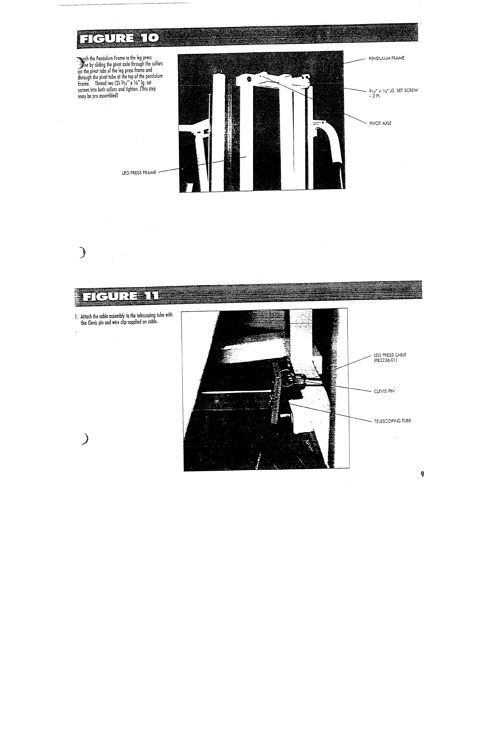
. _~.nch the Pendulum Frame to the leg press
e by sliding the pivot axle thrnugh the col!ars
on the pivot tabs of the leg press flame and
through the pivot tube at the top of the pendulum
flame. Thread two (2) sA6" x I/4" Ig. set
screws into both collars and tighten. {This ~ep
may be pre-nssembled)
PENDULUM FRAME
5/16" x 1/4~ LG SET SCR.~v’
-2 PL
PIVOT AXLE
LEG PRESS FI
1. Atlach the cable assembly to the telescoping tube with
the Clevis pin and wire clip supplied on cable.
LEG PRESS CABLE
(PB3236-01)
CLEVIS PiN
TELESCOPING TUBE
9
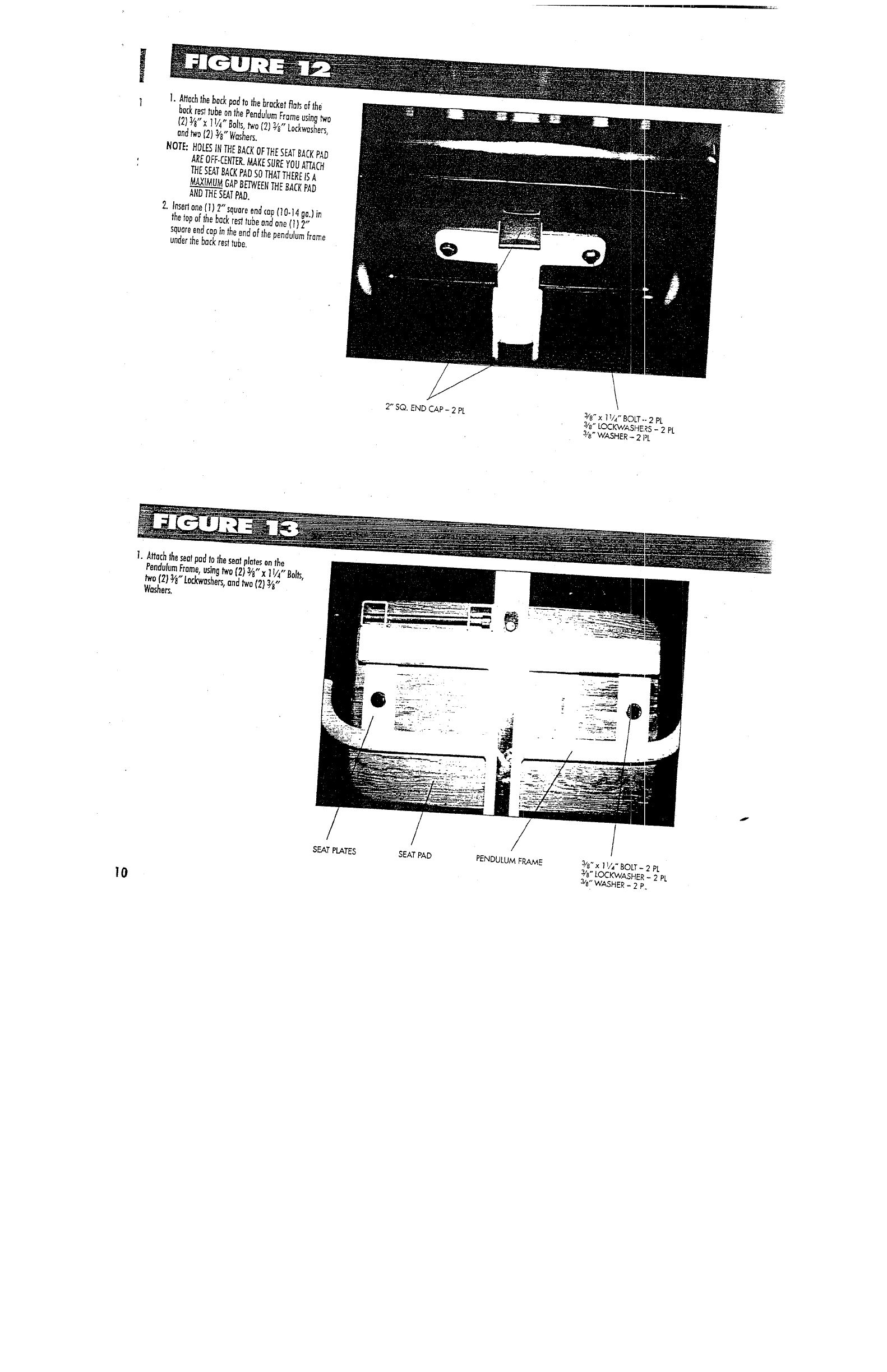
ock res~ tube on the Pendulum Frame using two(2).~/8"x 11/~’~Bohs
’ two (2) ~,~" Lockwashe~,
ana ~o ~2) ~8’ Washe~.
NOTE: HOL~ IN ~E BACK OF THE S~T BACK PAD
AND ~E S~T PAD.
2. Iflse~ on~ ( ~ ) 2"~quare ~nd cap ( ~ 0-14 g~;)in
the top ot ~he back re~ tuoe and one (1)
square end cop in the end of the pendulum frame
under ~he back rest tube.
2" SQ. END CAP - 2 PL 3/e" x 11/,,- BOLT -- 2 PL
3/e" LOCKWASHE~S _ 2 PL
3,,~ WASHER .- 2 PL
lure Frame, uu,,g two {’2) 3~ x ] i ,, " ....... ~-=
two " 8 74 Bolt~, "
f2) ~ Lockwasher% and two 121 ~"
Washers.
10
// /
SEAT PLATES .SEAT PAD PENDULUM FRAME 3/~ x 1 ~,,’~" BOLT - 2 PL
~’e" LOCKWASHER _ 2 PL
3/e" WASHER - 2 P.

~r
ten any loose connedions at this time.
FACTOR 625 should be assembled as
11
