Paradox Security Systems 1759EX Alarm Receiver User Manual 1759EXei01
Paradox Security Systems Alarm Receiver 1759EXei01
UserManual.wiki
>
Paradox Security Systems
>
1759EX User Manual
Users Manual
Navigation menu
Upload a User Manual
Namespaces
Wiki Guide
HTML
PDF
Info
Views
User Manual
Discussion / Help
Navigation


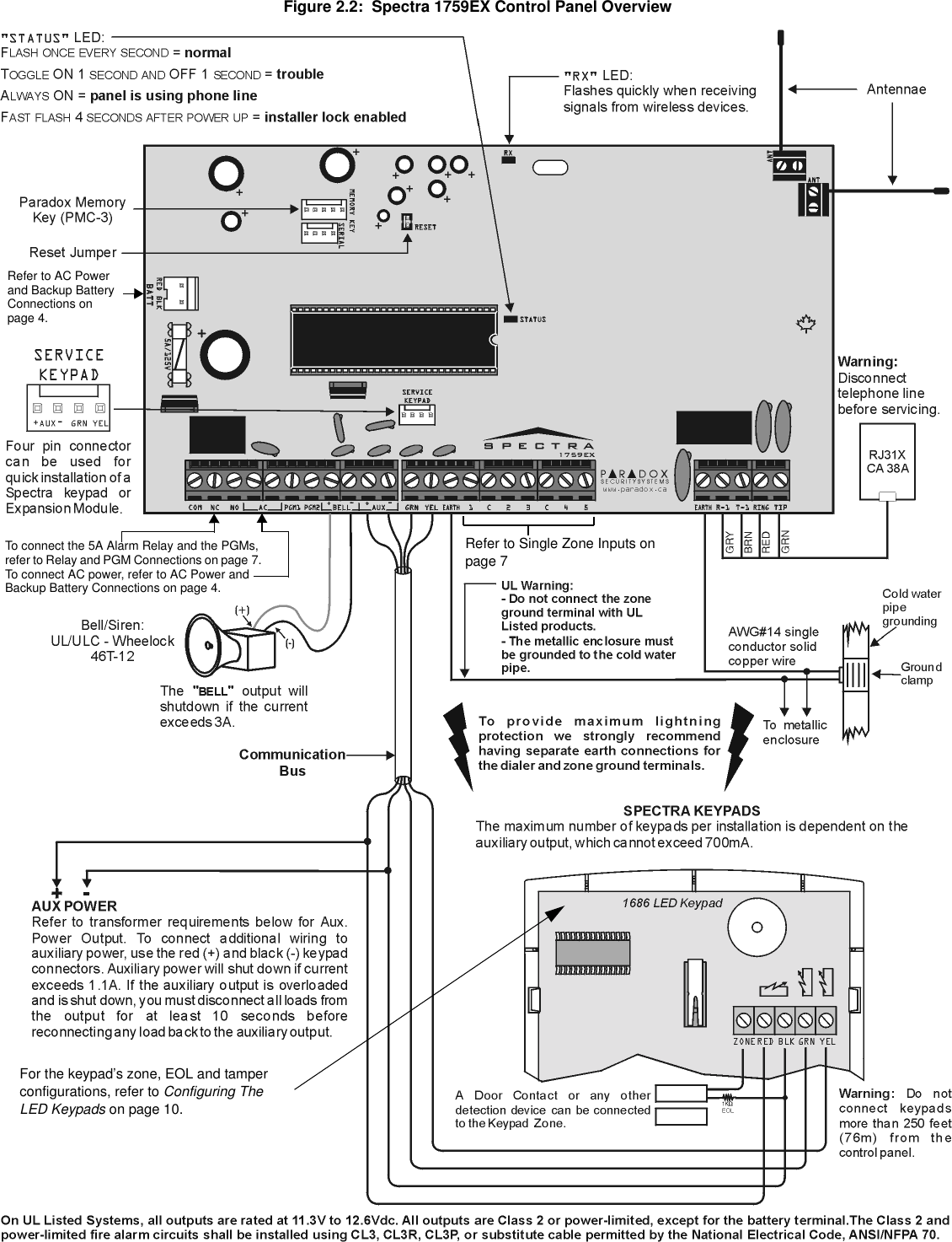
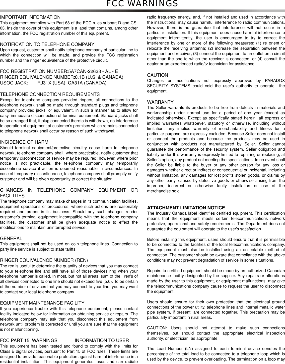
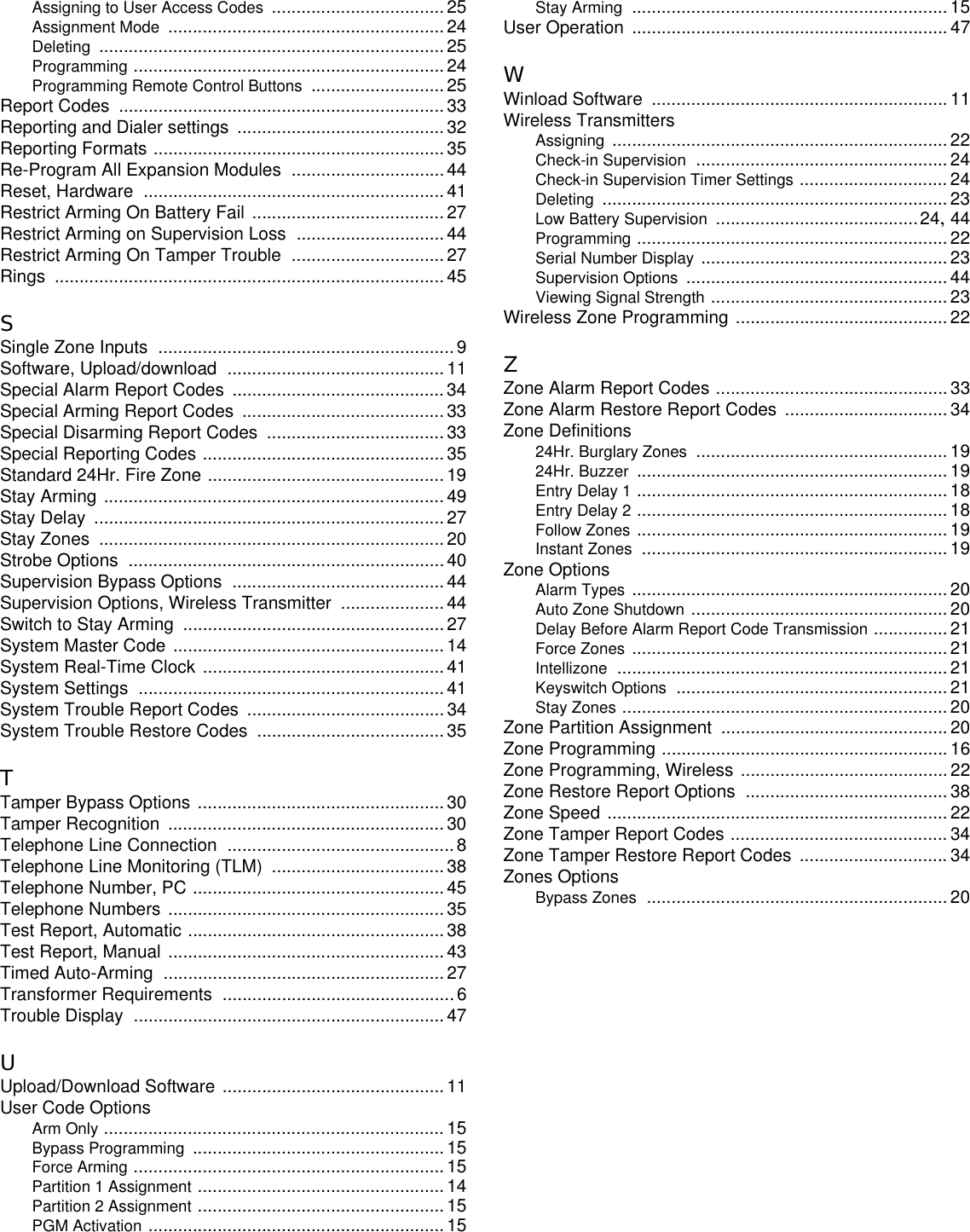
![Each keypad has one zone input terminal, allowing you to connect one motion detector or door contact directly to a keypad. Thekeypad can then communicate the status of the zone to the control panel. A maximum of two keypad zones can be used witheach control panel. After connecting the device, the zone's parameters must be defined. For details on zone recognition andZone Programming refer to page 14. Also, refer to the feature Reassign Keypad Zone 2 on page 14.Example: A door contact located at the entry point of an establishment can be wired directly to the input terminal of the entrypoint keypad instead of wiring the door contact all the way to the control panel.Figure 2.5: Keypad Zone Connections2.11 KEYSWITCH CONNECTIONSKeyswitches allow users to arm or disarm a partition by pushing a button or by activating aswitch with a key. Connect the keyswitch as shown in Figure 2.6 directly to the controlpanel terminals. Once a keyswitch is connected, it must be assigned to a zone and itsparameters must be programmed (see Zone Programming on page 14 and KeyswitchOptions on page 19).2.12 FIRE CIRCUITSWhen a zone is programmed as a Fire zone, the zone becomes normally open and requiresan EOL resistor. If a line short occurs or if the smoke detector becomes active, whether thesystem is armed or disarmed, the control panel will generate an alarm. If a trouble occurs on aFire zone, the Fire Loop Trouble will appear in the keypads’ Trouble Display (see page 45) andthe control panel can transmit the Fire Loop Trouble report, if programmed, in section [206].2.12.1 4-WIRE INSTALLATION:Any on-board zone can be defined as a Fire Zone (see page 16) when using the 4-wire installation. Connect the smoke detectors as shown in Figure 2.7 directly to thecontrol panel terminals. Program the PGM with the “[PG]/[FNC1] Key was Pressed”Activation Event (see page 37) so the smoke detectors can be reset by pressing the[PG]or[FNC1] key. Pressing the [PG]or[FNC1] key will interrupt power to the smokedetectors for 4 seconds (see PGM Delay on page 38).Figure 2.6: KeyswitchFigure 2.7: Fire Zones](https://usermanual.wiki/Paradox-Security-Systems/1759EX/User-Guide-270100-Page-10.png)
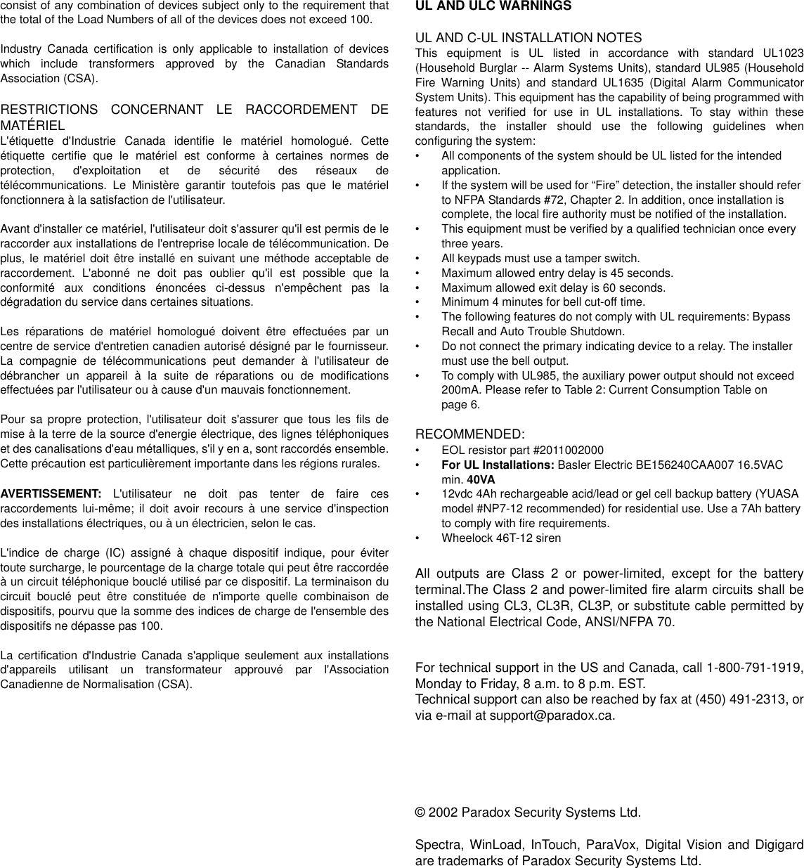
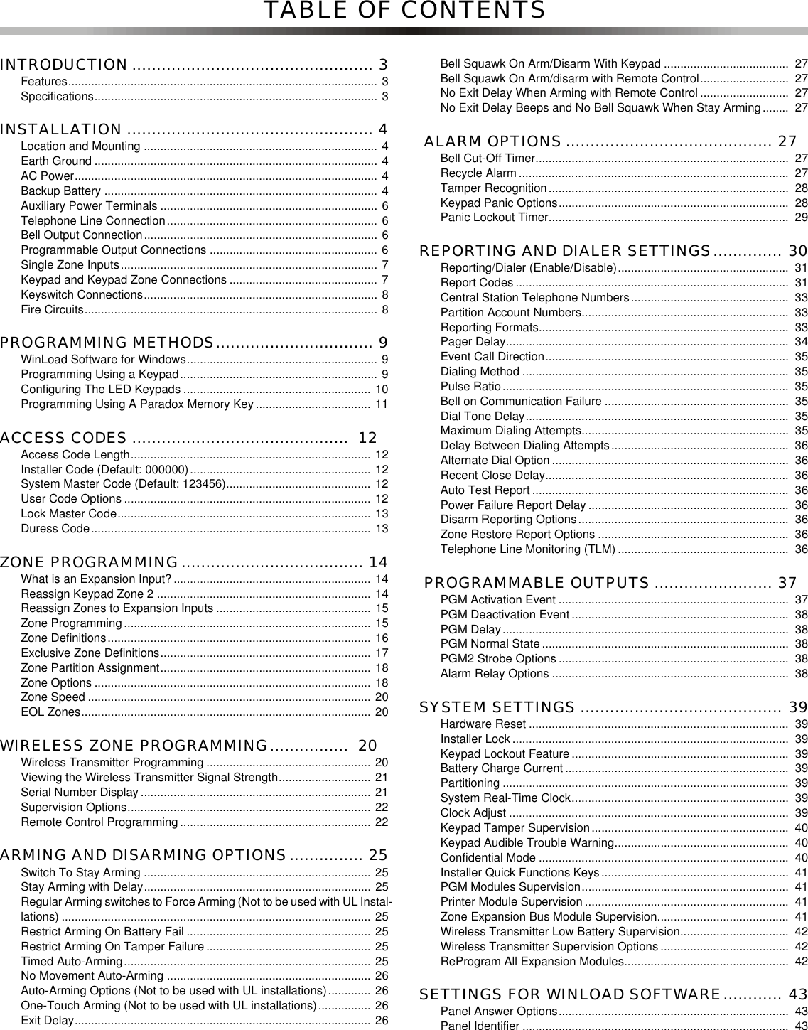
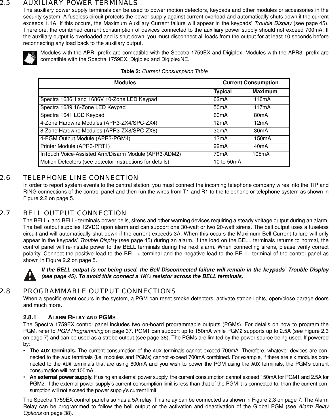
![PART 3: PROGRAMMING METHODS3.1 WINLOAD SOFTWARE FOR WINDOWSProgram the Spectra Series control panels remotely or on-site using the Winload Software for Windows®. For more information,contact your local Paradox Distributor or visit our web site at http://www.paradox.ca. If you are using the WinLoad software, youmust program the features explained on pages 43 and 44.3.2 PROGRAMMING USING A KEYPADUse the supplied Spectra 1759EX Programming Guide to keep track of which sections were programmed and how. Werecommend you read this entire manual before you begin programming.3.2.1 SINGLE DIGIT DATA ENTRY METHOD (HEXADECIMAL AND DECIMAL)Single Digit Data Entry is used in all sections except those specified in the Feature Select Programming Method. Afterentering the programming mode as described in the shaded box above, some sections will require that you enterDecimal values from 000 to 255. Other sections will require that you enter Hexadecimal values from 0toF.Therequired data will be clearly indicated in this manual as well as in the Spectra 1759EX Programming Guide. Whenentering the final digit in a section, the control panel will automatically save and advance to the next section. Exceptsections 001 to 016, after entering the first two digits the control panel will switch to Feature Select Programming.3.2.2 FEATURE SELECT PROGRAMMING METHODAfter entering sections [001] to [016], [126] to [138], and [302] to [348], each option from [1] to [8] represents a specificfeature or option. Press the key corresponding to the desired option and the corresponding light will illuminate or theoption number will appear in the LCD display. This means the option is on. Press the key again to extinguish thecorresponding light or remove the digit from the LCD display, thereby, turning off the option. Press the [FORCE]key toset all 8 options to off. Press the keys until the current section’s options are set. When the options are set, press the[ENTER]key to save and advance to the next section.3.2.3 DATA DISPLAY MODE (LED KEYPADS ONLY)In the Data Display Mode you can view the programmed contents of each section one digit at a time. After entering thedesired 3-digit section (see step 3 of the shaded box on page 9), press the [ENTER]key to access the Data DisplayMode (will not function with sections using Multiple Feature Select Programming).How Do I Enter Programming Mode?STEP 1: Press [ENTER]STEP 2: Enter your [INSTALLER CODE] (default: 000000)STEP 3: Enter 3-digit [SECTION] you wish to programSTEP 4: Enter required [DATA]Table 3:Decimal and Hexadecimal Programming TableValue or Action What Do I Press? What Do I See?10-Zone LED 16-Zone LED LCDValues1to9 [1]to[9][1]to[9] [1]to[9] [1]to[9]A (hexa only) [0] [0 (10)] [10] 0B (hexa only) [STAY][STAY][11] BC (hexa only) [BYP][BYP] [12] CD (hexa only) [MEM][MEM] [13] DE (hexa only) [TBL]/[TRBL][TBL] [14] EF (hexa only) [PG]/[FNC1] [PG] [15] FExit Without Saving [CLEAR][ENTER] flashes [ARM1] & [STAY1] flash “SECTION [ ]”Insert Blank Digit [FORCE] Displays next digit or next sectionSave Data [ENTER] Advances to the next section](https://usermanual.wiki/Paradox-Security-Systems/1759EX/User-Guide-270100-Page-11.png)
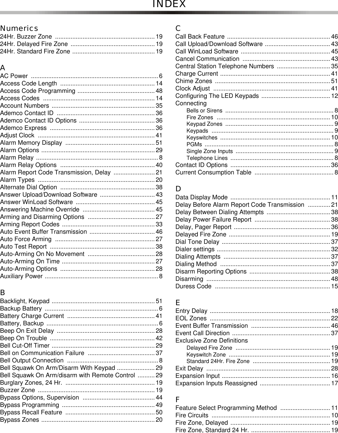
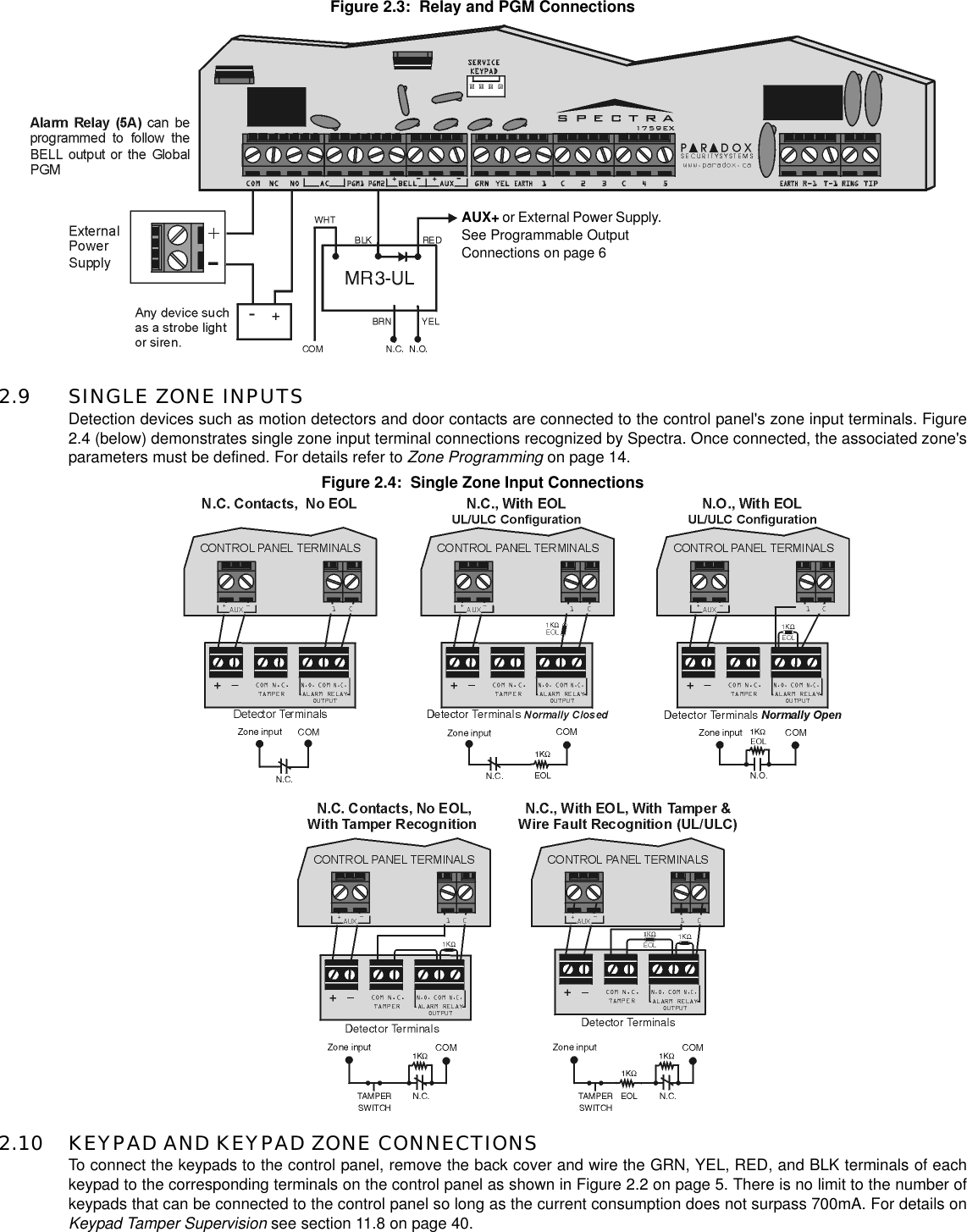
![Figure 3.1: Data Display Mode (LED Keypads Only)3.3 CONFIGURING THE LED KEYPADSDepending on the version of the keypad, two methods can be used to configure the LED keypads (1686H, 1686V and 1689):3.3.1 CONFIGURING THE 1686H, 1686V AND 1689 KEYPADS V2.0 OR HIGHERThe keypad’s zone number, EOL definition and tamper switch are programmed through the control panel’sprogramming mode. To do so:PLEASE NOTE: After two minutes, the keypad exits programming mode.Key [1] - Keypad Zone SelectionKey [1] determines whether the keypad’s zone is Keypad Zone 1 or Keypad Zone 2. When key [1] is OFF (notilluminated), the keypad’s zone is Keypad Zone 1. When key [1] is ON (illuminated), the keypad’s zone is Keypad Zone 2.Key [1] OFF - Keypad Zone 1 (default)Key [1] ON - Keypad Zone 2Key [2] - EOL DefinitionKey [2] determines the keypad zone’s EOL definition. When key [2] is OFF (not illuminated), EOL is disabled and thekeypad zone will use the on-board EOL resistor. When key [2] is ON (illuminated), EOL is enabled and the keypadzone requires that an external EOL resistor be connected (refer to Spectra 1759EX Control Panel Overview on page 5for more details).Key [2] OFF - EOL disabledKey [2] ON - EOL enabled (default)Key [3] - On-Board TamperKey [3] enables or disables the keypad’s on-board tamper switch. When key [3] is OFF (not illuminated), the tamperswitch is disabled. When key [3] is ON (illuminated), the tamper switch is enabled.Key [3] OFF - On-board tamper switch disabledKey [3] ON - On-board tamper switch enabledHow Do I Configure The Keypad?STEP 1: Press [ENTER]STEP 2: Enter your [INSTALLER CODE] (default: 000000)STEP 3: Press the [PG] (1686H/V) / [FNC1] (1689) key and hold it for 3 seconds.STEP 4: Press the desired key ([1] to [3]. See below)STEP 5: Press [ENTER] to exit programming modeTo access the Data Display Mode, press the [enter] key after entering a section and before entering any data. The three LEDs as indicated will beginto flash indicating that you are in the Data Display Mode.Each time the [ENTER]key is pressed, the keypad will display the next digit in the current section and will continue through all the following sectionsone digit at a time without changing the programmed values. Not available for sections using the Multiple Feature Select Method. Press the [CLEAR]key at any time to exit the Data Display Mode.1686H1686V 1689](https://usermanual.wiki/Paradox-Security-Systems/1759EX/User-Guide-270100-Page-12.png)
![PLEASE NOTE: The keypad can be ordered with or without a tamper switch. If the keypad has notamper switch, key [3] will be OFF by default. If the keypad has a tamper switch, key [3] will be ON bydefault.3.3.2 CONFIGURING THE 1686H, 1686V AND 1689 KEYPADS PRIOR TO V2.0The keypad’s zone number and EOL definition are defined through the jumpers located on the PCB board. Thejumpers are as follows:J1 - Keypad Zone Select JumperJumper J1 determines whether the keypad’s zone is Keypad Zone 1 or Keypad Zone 2. When the jumper is OFF, thekeypad’s zone is Keypad Zone 2. When the jumper is ON, the keypad’s zone is Keypad Zone 1.J1 OFF - Keypad Zone 2J1 ON - Keypad Zone 1J2 - EOL Definition JumperJumper J2 determines the keypad zone’s EOL definition. When the jumper is OFF, EOL is disabled and the keypad zoneuses the on-board EOL resistor. When the jumper is ON, EOL is enabled and the keypad zone requires that an externalEOL resistor be connected (refer to Spectra 1759EX Control Panel Overview on page 5 and more details).J2 OFF - EOL disabledJ2 ON - EOL enabled3.4 PROGRAMMING USING A PARADOX MEMORY KEYCopy the sections of one Spectra control panel into the Paradox Memory Key (PMC-3). Then copy the contents of the MemoryKey into as many Spectra control panels as needed. Each panel is programmed in less than 3 seconds.Download to DESTINATION Control Panel1) Remove AC and battery power from the control panel.2) Place the Memory Key on the serial connector labeled KEY of the Spectra Control Panel that isto receive the contents of the Memory Key.3) Reapply AC and battery power.4) In installer programming mode, enter section [900], then press [ENTER]to acknowledge.5) When the keypad emits a Confirmation Beep, remove the Memory Key.6) Enter section [750] to reprogram the modules with the information downloaded from theParadox Memory Key.Copy to Memory Key from SOURCE Control Panel1) Remove AC and battery power from the control panel.2) Place Memory Key on the serial connector labeled KEY of the Spectra Control Panel that youwant to copy. Make sure the write protect jumper of the Memory Key is on.3) Reapply AC and battery power.4) In installer programming mode, enter section [902], then press [ENTER]to acknowledge.5) When the keypad emits a Confirmation Beep, remove the Memory Key. Remove the MemoryKey’s jumper if you do not wish to accidentally overwrite its contents.Figure 3.2: Paradox Memory Key](https://usermanual.wiki/Paradox-Security-Systems/1759EX/User-Guide-270100-Page-13.png)
![PART 4: ACCESS CODESThe Spectra 1759EX control panel supports the following access codes:4.1 ACCESS CODE LENGTHSection [127]: System OptionsOption [2] OFF = 6-Digit Access Codes Option [2] ON = 4-Digit Access Codes (default)All access codes can be set to lengths of either 4- or 6-digits. When the 4-digit option is selected, entering a 4-digit code will allowaccess. Using the 6-digit option, entering 6 digits is required to allow access.If the Access Code Length is changed from four digits to six digits when access codes have already beenprogrammed, the control panel will automatically add the last 2 digits by using the first 2 digits. For example, ifthe access code is 1234 and you switch to 6 digits, the code will become 123412. Be sure to verify the accesscodes after switching from 4-digit access codes to 6-digit codes. When switching from six digits to four digits,the control panel will simply remove the final two digits of the access code. For example, 123456 will become1234.4.2 INSTALLER CODE (Default: 000000) The Installer Code is used to enter the control panel's programming mode (see page 9), which allows you to program all thefeatures, options and commands of the control panel. The Installer Code can be 4- or 6-digits in length (see above) where eachdigit can be any value from 0 to 9. The Installer Code cannot be used to program Master Code 1,Master Code 2 or User AccessCodes. To program the Installer Code press:[ENTER]+[CURRENT INSTALLER CODE]+[281] +new 4- or 6-digit Installer Code4.3 SYSTEM MASTER CODE (Default: 123456)The Installer Code canbeusedtoprogramtheSystem Master Code. With the System Master Code a user can use any armingmethod and can program any User Access Code, but not the User Code Options.TheSystem Master Code canbe4or6digitsin length (see section 4.1), where each digit can be any digit from 0 to 9. To change the System Master Code press:[ENTER]+[INSTALLER CODE]+[301] +new 4- or 6-digit System Master Code4.4 USER CODE OPTIONSSections [302] to [348]: Options [1] to [7]The User Code Options define which arming methods each user can use to arm or disarm the system. Regardless of thesesettings, all users can Regular Arm assigned partitions and all users except those with the Arm Only option can disarm anassigned partition, regardless of how it is armed. Select one or more of the options described on the following pages for eachUser Access Code, where sections [302] to [348] represent User Access Codes 002 to 048. For information on how User AccessCodes are programmed, please refer to page 46.4.4.1 PARTITION 1ASSIGNMENTSections [302] to [348]: User Codes 002 to 048Option [1] OFF = Deny access to partition 1 Option [1] ON = User code has access to partition 1 (default)If Partitioned (see page 39), user codes with this option enabled can arm and disarm partition 1.If the system is not partitioned, you must assign partition 1 to the User Access Code. Otherwise, theUser Access Code will be considered disabled.INSTALLER CODE: Used to program all control panel settings except User Access Codes.SYSTEM MASTER CODE (001) Provides full access. Arm and disarm using any method described in the User Code Optionsin section 4.4 as well as program the User Access Codes.Master Code 1 (002): Permanently assigned to partition 1. Same as a regular User Code except it can alsoprogram access codes for User Codes assigned to partition 1.Master Code 2 (003): Permanently assigned to partition 2. Same as a regular User Code except it can programaccess codes for User Codes assigned to partition 2. If the system is not partitioned MasterCode 002 will be assigned to partition 1.45 User Codes (004 to 048): Can arm and disarm as per User Code Options in section 4.4.](https://usermanual.wiki/Paradox-Security-Systems/1759EX/User-Guide-270100-Page-14.png)
![4.4.2 PARTITION 2ASSIGNMENTSections [302] to [348]: User Codes 002 to 048Option [2] OFF = Deny access to partition 2 (default)Option [2] ON = User code has access to partition 2If the system is partitioned (see page 39), user codes with this option enabled can arm and disarm partition 2. If thesystem is not partitioned, the control panel ignores this option.4.4.3 BYPASS PROGRAMMINGSections [302] to [348]: User Codes 002 to 048Option [3] OFF = Bypass Programming Disabled Option [3] ON = Bypass Programming Enabled (default)User codes with this option enabled can perform Bypass Programming in assigned partitions.4.4.4 STAY ARMINGSections [302] to [348]: User Codes 002 to 048Option [4] OFF = Stay Arming Disabled Option [4] ON = Stay Arming Enabled for selected User Code (default)User codes with this option enabled can Stay Arm assigned partitions.4.4.5 FORCE ARMINGSections [302] to [348]: User Codes 002 to 048Option [5] OFF = Force Arming Disabled (default)Option [5] ON = Force Arming Enabled for selected User CodeUser codes with this option enabled can Force Arm assigned partitions.4.4.6 ARM ONLYSections [302] to [348]: User Codes 002 to 048Option [6] OFF = Arm Only Disabled (default)Option [6] ON = Arm Only Enabled for selected User CodeThe user code with this option enabled can arm assigned partitions, but cannot disarm any partitions. The type ofarming is dependent on the other User Code Options selected. Please note that with the Arm Only option, the user cancancel a recently armed system by re-entering the access code before the end of the Exit Delay.4.4.7 PGM ACTIVATIONSections [302] to [348]: User Codes 002 to 048Option [7] OFF = User Code follows User Code Options and can activate a PGM (default)Option [7] ON = User Code can activate a PGM only With option [7] off, entering the access code will arm or disarm according to the programmed User Code Options aswell as activate or deactivate a PGM. The appropriate PGM Activation/Deactivation Event must also be programmed(see page 37). With option [7] on, the control panel will ignore all other User Code Options. Therefore, entering theaccess code will only activate or deactivate the PGM.4.5 LOCK MASTER CODESection [127]: System OptionsOption [4] OFF = Lock System Master Code Disabled (default)Option [4] ON = Lock System Master Code EnabledWith this feature enabled, the control panel will lock the System Master Code (001). This means that the System Master Codecannot be deleted, but it can be changed.4.6 DURESS CODESection [127] = System OptionsOption [6] OFF = Duress Code Disabled (default)Option [6] ON = User Code 048 becomes a Duress codeWith this feature enabled, User Code 048 becomes a Duress Code. When forced to arm or disarm their system, users can entera Duress Code (User Code 048) to arm or disarm the system which can immediately transmit a silent alert to the Central Station,transmitting the duress report code programmed in section [196].](https://usermanual.wiki/Paradox-Security-Systems/1759EX/User-Guide-270100-Page-15.png)
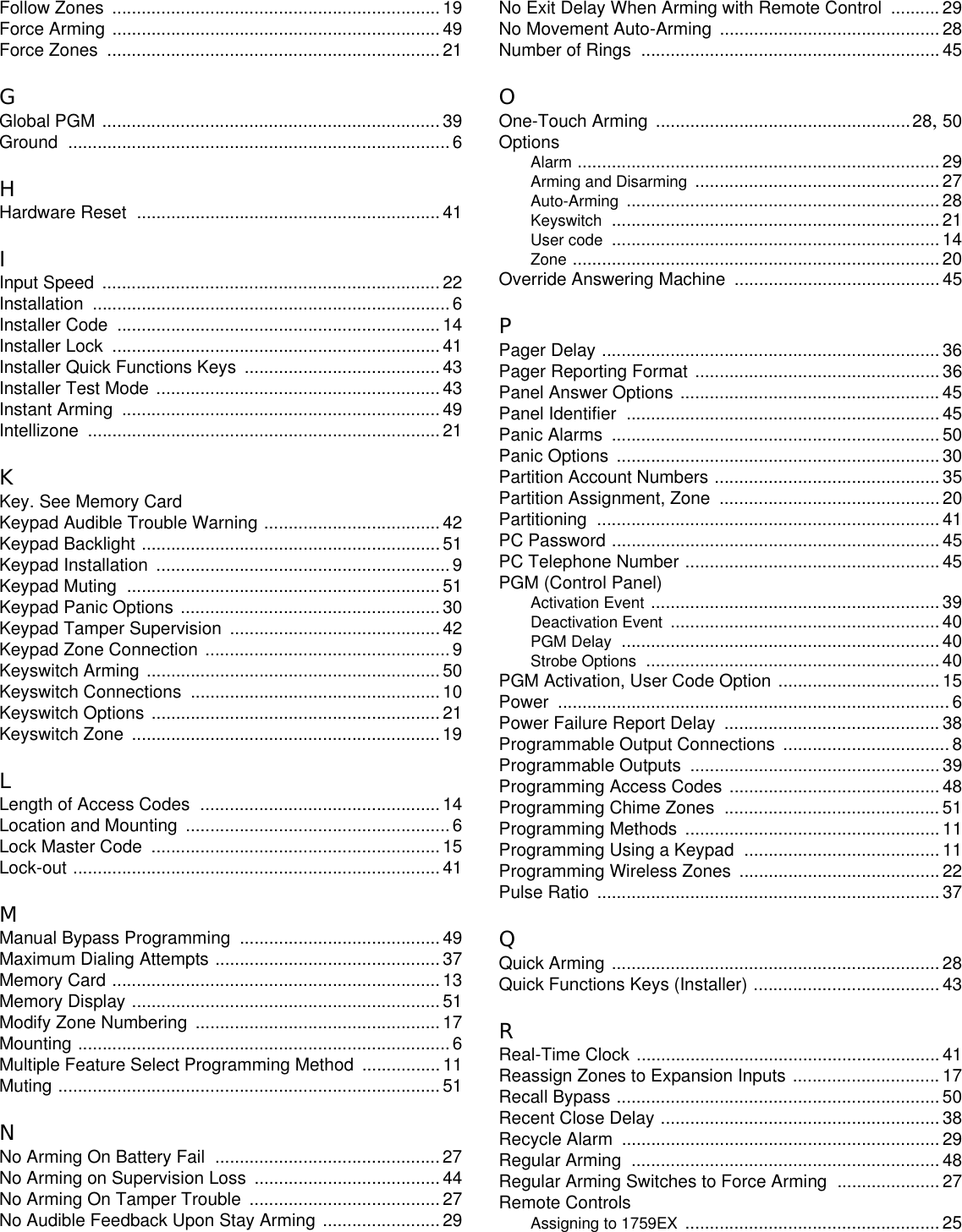
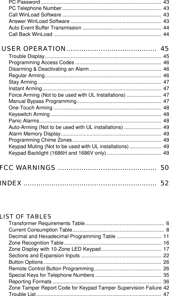
![PART 5: ZONE PROGRAMMINGThe Spectra 1759EX control panel’s zone assignment depends on where the detection devices are connected (see Table 4).5.1 WHAT IS AN EXPANSION INPUT?An expansion input allows you to connect modules to the system to increase the number of zones available up to 15 zones. Eachhardwired input on a zone expansion bus module or wireless transmitter can be assigned to an expansion input. The expansioninputs can be used in any combination. For example, 5 wireless transmitters and 3 hardwire inputs can be assigned to theexpansion inputs. Spectra control panels cannot support more than eight expansion inputs. Refer to the appropriate module’sInstruction Sheet for details.Do not assign inputs from different modules to the same expansion input.5.2 REASSIGN KEYPAD ZONE 2Section [126]: General OptionsOption [7] OFF = Reassign Keypad Zone 2 Disabled (default)Option [7] ON = Reassign Keypad Zone 2 EnabledReassign Keypad Zone 2 changes the keypad zone into an expansion input. In Table 4 above, the effects of enabling this featureare shown. For example, when option [7] is enabled, Zone 4 moves to Expansion Input 1 (see Table 5 on page 15). Then, you areable to use Expansion Input 1.When Reassign Keypad Zone 2 is enabled, the Keypad Tamper Supervision (see page 40) for keypad zone 2 islost. Keypad Tamper Supervision will ONLY function on Keypad Zone 1.Table 4:Zone Recognition TableDevice connected towhich input? 1759EXControl PanelInput 1 = Zone 1Input 2 = Zone 2Input 3 = Zone 3Input 4 = Zone 4Input 5 = Zone 5KeypadZone 1 = Zone 6Zone 2 = Zone 7ExpansionInput 1 = Zone 8Input 2 = Zone 9Input 3 = Zone 10Input 4 = Zone 11Input 5 = Zone 12Input 6 = Zone 13Input 7 = Zone 14Input 8 = Zone 15](https://usermanual.wiki/Paradox-Security-Systems/1759EX/User-Guide-270100-Page-16.png)
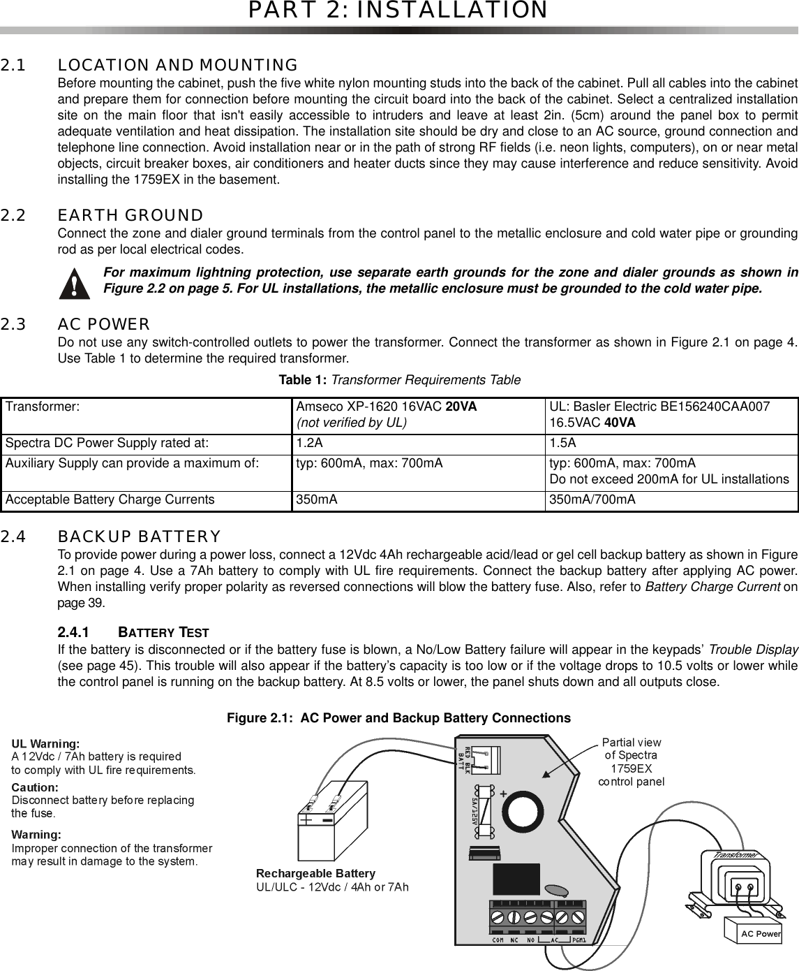
![5.3 REASSIGN ZONES TO EXPANSION INPUTSSection [126]: General OptionsOption [8] OFF = Reassign Zones to Expansion Inputs Disabled (default)Option [8] ON = Reassign Zones to Expansion Inputs EnabledReassign Zones to Expansion Inputs changes the zone numbering to increase the number of expansion inputs that can bedisplayed on 10-Zone LED Keypads. In installations that require using mostly the expansion inputs, such as using wirelesszones, the 10-Zone LED Keypads may be unable to display some of the zones. In the following table, the effects of enabling thisfeature and Reassign Keypad Zone 2 ( see section 5.2 on page 14) are shown:5.4 ZONE PROGRAMMINGAfter connecting a hardwired detection device to one of the control panel's or zone expansion bus module’s input terminals orafter setting up any wireless transmitters, define the associated zone's parameters. The Zone Parameters define the type ofzone, the zone's partition assignment and how the control panel will react when an alarm condition occurs on that zone. TheseZone Parameters are programmed into one section as detailed in Figure 5.1 on page 16.Only the control panel’s on-board inputs can be defined as a Fire, Delayed Fire or a Keyswitch zone. The on-board zones are zones 01 to 05.Table 5:Zone Display with 10-Zone LED KeypadOption [8]:OFF Option [8]:ONOption [8]: ON andOption [7]: OFF (Reassign Keypad Zone 2)Option [8]: ON andOption [7]: ON (Reassign Keypad Zone 2)1759EX 1759EX 1759EX 1759EXControl PanelInput 1 = Zone 1 Zone 1 Zone 1 Zone 1Input 2 = Zone 2 Zone 2 Zone 2 Zone 2Input 3 = Zone 3 N/A N/A N/AInput 4 = Zone 4 N/A N/A N/AInput 5 = Zone 5 N/A N/A N/AKeypadZone1= Zone 6 Zone 3 Zone 3 Zone 3Zone2= Zone 7 Zone 4 Zone 4 N/AExpansionInput 1 = Zone 8 Zone 5 Zone 5 Zone 4Input 2 = Zone 9 Zone 6 Zone 6 Zone 5Input 3 = Zone 10 Zone 7 Zone 7 Zone 6Input 4 = Zone 11 Zone 8 Zone 8 Zone 7Input 5 = Zone 12 Zone 9 Zone 9 Zone 8Input 6 = Zone 13 Zone 10 Zone 10 Zone 9Input 7 = Zone 14 Zone 11 Zone 11 Zone 10Input 8 = Zone 15 Zone 12 Zone 12 Zone 11= not displayed on 10-Zone LED Keypads](https://usermanual.wiki/Paradox-Security-Systems/1759EX/User-Guide-270100-Page-17.png)
![Figure 5.1: Spectra Zone Programming5.5 ZONE DEFINITIONSAs demonstrated in Figure 5.1, sections [001] to [015] represent zones 1 through 15 respectively, where the first digit in each ofthese sections represents the zone's definition. Also, refer to Zone Speed on page 20. To disable a zone, clear the contents ofthe section corresponding to the desired zone by pressing the [FORCE]key 3 times and pressing [ENTER]. There are 9 availableZone Definitions, which are described as follows.5.5.1 ENTRY DELAY 1Sections [001] to [015]: Zones 1 to 15, First Digit = 1When the system is armed and a zone defined with Entry Delay 1 opens, the control panel will generate an alarm afterthe programmed Entry Delay 1 Timer elapses. This is to provide users with enough time to enter the protected areaand disarm the system. To program the Entry Delay 1 Timer, key in the desired 3-digit delay value (000 to 255seconds, Default = 45 seconds) into section [069]. Entry Delay zones are commonly used at the entry/exit points of theprotected area (i.e. front/back door, garage, etc.). Using different Entry Delays (see Entry Delay 2) is useful when, forexample, one entry point requires a longer delay than the other entry point or in a partitioned system where eachpartition may require a different Entry Delay.5.5.2 ENTRY DELAY 2Sections [001] to [015]: Zones 1 to 15, First Digit = 2Entry Delay 2 zones are identical to the Entry Delay 1 zones (see section 5.5.1), except it uses a separate Entry DelayTimer. To program the Entry Delay 2 Timer, key in the desired 3-digit delay value (000 to 255 seconds, Default = 45seconds) into section [070].This timer is also used as the Stay Delay timer (see section 7.2).Zone Definitions1-Entry Delay 12-Entry Delay 23-Follow4-Instant5-24Hr. Burglary6-24Hr. BuzzerAdditional definitions foron-board terminals:7-Keyswitch8-24Hr. Fire9-24Hr. Delayed FirePress the[ENTER]keyEnter the[INSTALLER CODE]Key in 3-digit[SECTION]Zone DefinitionFirst DigitZone PartitionAssignmentSecond DigitZone OptionsFeature SelectPress [ENTER][001] =Zone1 [009] =Zone9[002] =Zone2 [010] =Zone10[003] =Zone3 [011] =Zone11[004] =Zone4 [012] =Zone12[005] =Zone5 [013] =Zone13[006] =Zone6 [014] =Zone14[007] =Zone7 [015] =Zone15[008]=Zone8Zone Partition Assignment1-Zone Assigned to Partition 12-Zone Assigned to Partition 23-Zone Assigned to both PartitionsZone Options[1] Auto Zone Shutdown Enabled[2] Bypass Enabled[3] Stay Zone[4] [5] Zone Alarm TypeOFF OFF Audible Alarm (steady)OFF ON Audible Alarm (pulsed)ON OFF Silent AlarmON ON Generates only a report[6] Intellizone[7] Delay alarm transmission[8] Force ZoneKeyswitch Options[1] OFF= MaintainedON = Momentary[2] OFF = Regular ArmON = Stay ArmKeypads beep twiceSelectone Selectone](https://usermanual.wiki/Paradox-Security-Systems/1759EX/User-Guide-270100-Page-18.png)
![5.5.3 FOLLOW ZONESSections [001] to [015]: Zones 1 to 15, First Digit = 3When an armed Follow Zone opens, the control panel will immediately generate an alarm, unless an Entry Delay zoneopens first:• If an armed Follow Zone opens after an Entry Delay zone opens, the control panel waits until the Entry Delay Timerhas elapsed before generating an alarm.• If an armed Follow Zone opens after more than one Entry Delay zone opens, the control panel will wait until theEntry Delay Timer of the zone that opened first has elapsed.This feature is commonly used when a motion detector is protecting the area occupied by the entry point keypad. Thiswill prevent the motion detector from causing an alarm when a user enters through the entry point to disarm thesystem.5.5.4 INSTANT ZONESSections [001] to [015]: Zones 1 to 15, First Digit = 4When an armed Instant Zone opens, the control panel immediately generates an alarm. Instant Zones are commonlyused for windows, patio doors, skylights and other perimeter type zones.5.5.5 24HR.BURGLARY ZONESSections [001] to [015]: Zones 1 to 15, First Digit = 5Whenever a 24Hr. Burglary Zone opens, whether the system is armed or disarmed, the control panel will immediatelygenerate an alarm.5.5.6 24HR.BUZZERSections [001] to [015]: Zones 1 to 15, First Digit = 6Whenever a 24Hr. Buzzer Zone opens, whether the zone is armed or disarmed, the control panel sets off the keypads’buzzers to indicate that the zone was breached. The control panel will report the alarm, but will not enable the bell/siren output. Enter any valid access code on the keypad to stop the buzzer. This zone definition is particularly usefulwhen a user wishes to be notified when something such as a safe or locker within the home has been accessed (i.e. achild accessing a valuable collection).5.6 EXCLUSIVE ZONE DEFINITIONSThe following three zone definitions can only be used for devices connected directly to the control panel’s on-board inputterminals. When a zone is programmed as a Keyswitch Zone, the control panel will ignore all other Zone Options. When a zone isprogrammed as a Standard Fire Zone or Delayed Fire Zone, the control panel will ignore the Zone Options that may have beenprogrammed, except Auto Zone Shutdown. Wireless devices and devices connected to the zone expansion bus modules cannotbe programmed with these definitions.5.6.1 KEYSWITCH ZONESections [001] to [005]: Zones 1 to 5, First Digit = 7Connecting a keyswitch to a zone allows users to arm the system by pressing a button or by turning a switch on or offwith a key. Please refer to Keyswitch Connections on page 8 and to Keyswitch Options on page 19.5.6.2 STANDARD 24HR.FIRE ZONESections [001] to [005]: Zones 1 to 5, First Digit = 8Whenever a Standard 24Hr. Fire Zone opens, whether it is armed or disarmed, the control panel will generate thefollowing:• The control panel can send the corresponding Alarm Report Code from sections [187] to [190].• If a tamper/wiring fault occurs on a Fire Zone, the control panel can send a Fire Loop Trouble report codeprogrammed in section [206] to the Central Station. The keypads will display a Fire Loop Trouble in their TroubleDisplay (see page 45).• Alarms are always audible regardless of other settings. Fire alarms generate an intermittent (pulsed) bell/sirenoutput signal as shown in Figure 5.2 on page 18.For information on how to connect smoke detectors to the control panel, refer to Fire Circuits on page 8.5.6.3 DELAYED FIRE ZONESections [001] to [005]: Zones 1 to 5, First Digit = 9When a Delayed 24Hr. Fire Zone opens, whether it is armed or disarmed, the control panel will react as shown inFigure 5.3 on page 18. Delayed 24Hr. Fire Zones are commonly used in residential homes where a smoke detectoroften generates false alarms (i.e. burning bread, etc.).](https://usermanual.wiki/Paradox-Security-Systems/1759EX/User-Guide-270100-Page-19.png)
![5.7 ZONE PARTITION ASSIGNMENTSections [001] to [015]: Zones 1 to 15The control panel provides the option of partitioning the security systeminto two completely independent systems. As demonstrated in Figure 5-1on page 16, sections [001] to [015] represent zones 1 through 15respectively, where the second digit in each of these sections representsthe zone's partition assignment. The zone is assigned to Partition 1 ifsecond digit = 1, Partition 2 if second digit = 2, or both partitions issecond digit = 3. For details on Partitioning, refer to page 39.5.8 ZONE OPTIONSAs demonstrated in Figure 5.1, sections [001] to [015] represent zones 1through 15 respectively. After entering the first two digits, select one ormore of the following Zone Options by using the Multiple Feature SelectProgramming Method (see page 9):5.8.1 AUTO ZONE SHUTDOWNSections [001] to [015] = Zones 1 to 15Option [1] OFF = Auto Zone Shutdown Disabled Option [1] ON = Auto Zone Shutdown Enabled for selected zone (default)If, in a single armed period, the number of alarms generated bya zone with the Auto Zone Shutdown option enabled exceedsthe number defined by the Auto Zone Shutdown Counter, thecontrol panel will no longer generate an alarm for that zone. Toprogram the Auto Zone Shutdown Counter, key in the desiredlimit (000=Disabled, 001 to 015, Default = 5) into section [089].The Auto Zone Shutdown Counter resets every time thesystem is armed.5.8.2 BYPASS ZONESSections [001] to [015] = Zones 1 to 15Option [2] OFF = Bypass Zone Disabled Option [2] ON = Selected Zone is Bypass Enabled (default)When a user, utilizes the Bypass Programming feature (see page 47), only zones with the Bypass option enabled canbe programmed as bypassed.Do not program a Fire Zone with the Bypass option, as the control panel will never bypass Fire Zones.5.8.3 STAY ZONESSections [001] to [015]: Zones 1 to 15Option [3] OFF = Stay Zone Disabled (default)Option [3] ON = Selected Zone is Stay EnabledZones with the Stay option enabled will be bypassed when the system is Stay Armed (see page 47).Do not program a Fire Zone with the Stay option, as the control panel will never bypass Fire Zoneswhen Stay Arming.5.8.4 ALARM TYPESSections [001] to [015]: Zones 1 to 15[4] OFF / [5] OFF: Audible Steady (default)When the conditions for an alarm have been met, the control panel can transmit the appropriate Zone Alarm reportcode (see page 31) and provides a steady output for any bells or sirens connected to the control panel’s bell output.Figure 5.2: Bell Output During Fire Alarm Figure 5.3: Delayed 24Hr. Fire Zone](https://usermanual.wiki/Paradox-Security-Systems/1759EX/User-Guide-270100-Page-20.png)
![[4] OFF / [5] ON: Audible Pulsed AlarmWhen the conditions for an alarm have been met, the control panel can transmit the appropriate Zone Alarm reportcode (see page 31) and provides a pulsed output (see Figure 5-2 on page 18) for any bells or sirens connected to thecontrol panel’s bell output.[4] ON / [5] OFF: Silent AlarmWhen the conditions for an alarm are met, the control panel can transmit the appropriate Zone Alarm report code (seepage 31) and will not activate the control panel’s bell output. The appropriate ARM or STATUS LED on the keypads willflash to indicate an alarm and the user will still have to disarm the system.[4] ON / [5] ON: Report OnlyWhen the conditions for an alarm have been met, the control panel can transmit the appropriate Zone Alarm reportcode (see page 31). The system will not have to be disarmed.5.8.5 INTELLIZONESections [001] to [015]: Zones 1 to 15Option [6] OFF = Intellizone Disabled (default)Option [6] ON = Intellizone Enabled for Selected ZoneThis feature reduces the possibility of false alarms. When a zone with the Intellizone option opens, the panel does notimmediately generate an alarm. First it triggers the Intellizone Delay Timer.To program the Intellizone Delay Timer, keyin the desired 3-digit value (010 to 255 seconds, Default = 48 seconds) into section [084]. If any of the followingconditions occur during this period, the panel will generate an alarm:• During the Intellizone Delay, a second zone has caused an alarm.• During the Intellizone Delay, the zone in alarm has restored (closed) and re-occurred (opened).• The zone in alarm remains open for the entire Intellizone Delay.5.8.6 DELAY BEFORE ALARM REPORT CODE TRANSMISSIONSections [001] to [015]: Zones 1 to 15Option [7] OFF = Delay Alarm Transmission Disabled (default)Option [7] ON = Delay Alarm Transmission Enabled for Selected ZoneWhen an alarm condition occurs on a zone with this option enabled, the control panel enables the bell/siren output, butdoes not report the alarm to the central station until the end of the Alarm Before Transmission Delay. To program theAlarm Transmission Delay, key in the desired 3-digit delay value (000 = Disabled, 001 to 255 seconds) into section[080]. During this period, disarming the system disables the bell/siren output and cancels the report code transmission.This feature is commonly used with Entry Delay zones to reduce false alarms created by new users who may notdisarm the system in time.5.8.7 FORCE ZONESSections [001] to [015]: Zones 1 to 15Option [8] OFF = Force Zone Disabled (default)Option [8] ON = Selected Zone is Force EnabledAny open Force Zones at the time of arming will be considered deactivated by the control panel (see page 47). Ifduring this period a deactivated zone is closed, the control panel will revert that zone to active status. Consequently,the control panel will generate an alarm if the zone is breached.Do not program a Fire Zone with the Force option, as the control panel will never bypass Fire Zoneswhen Force Arming.5.8.8 KEYSWITCH OPTIONSSections [001] to [005]: Option [1] and [2]When an on-board zone is programmed as a Keyswitch Zone (see section 5.6.1 on page 17), the control panel willignore any other Zone Option. The keyswitch can be programmed as a Maintained or Momentary Keyswitch and toRegular or Stay Arm (see section 13.4 on page 46). A Maintained Keyswitch will arm the system when it is set to theON position and will disarm when set to the OFF position. To arm with a Momentary Keyswitch, set the keyswitch to theON position then turn it back to the OFF position. Repeating this sequence will disarm the system. Program thekeyswitch with the following:Option [1] OFF = Maintained (default) Option [2] OFF = Regular Arming (default)Option [1] ON = Momentary Option [2] ON = Stay Arming](https://usermanual.wiki/Paradox-Security-Systems/1759EX/User-Guide-270100-Page-21.png)
![5.9 ZONE SPEEDSections [050] to [064]: Zones 1 to 15 001 to 255 X 10ms, Default = 600msThe Zone Speed defines how quickly the control panel will respond to an open zone. The control panel will not display an openzone on the keypad or generate an alarm until the programmed Zone Speed has elapsed. All other zone definitions and optionsdo not come into effect until the Zone Speed has elapsed. This feature prevents any momentary glitches from causing an alarmor unnecessary reporting.5.10 EOL ZONESSection [132]: Zone OptionsOption [4] OFF = Zones do not use EOL resistors (default)Option [4] ON = Zones require EOL resistorsIf all detection devices connected to the control panel have input terminals that require 1KΩend of line resistors, enable option [4]in section [132]. For details on using EOL resistors, refer to see Single Zone Inputs on page 7.PART 6: WIRELESS ZONE PROGRAMMINGThe Spectra 1759EX allows for the addition of up to eight fully supervised Omnia wireless transmitters, and up to eight programmableremote controls.6.1 WIRELESS TRANSMITTER PROGRAMMINGThe programming of the wireless transmitters (detectors and door contacts) is accomplished in two steps:1. Assign the wireless transmitter to the Spectra 1759EX.2. Program the zones.6.1.1 ASSIGNING WIRELESS TRANSMITTERS TO THE RECEIVERSections [601] to [608]Sections [601] to [608] represent expansion inputs 1 to 8 respectively. For example, section [601] is assigned toexpansion input 1, section [602] is assigned to expansion input 2, etc. (refer to Table 6). Each Expansion Inputrepresents a specific zone in the Spectra 1759EX system (see Zone Recognition Table on page 14).Do not assign detection devices from different modules to the same expansion input. For example, donot assign a wireless transmitter to section [601] and then connect a detection device to input Z1 of theAPR3-ZX8.The serial number is located on the inside of the transmitter or you can use the Serial Number Display (refer tosection 6.3 on page 21) to determine its serial number.The transmitters must be activated once having been assigned to the Spectra 1759EX. To activate atransmitter, insert the batteries and close the cover. To ensure proper synchronization between the controlpanel and the transmitter, open and close the zone corresponding to the transmitter.Table 6:Sections and Expansion InputsSection # 6-digit Serial Number Expansion Input[601] ___/___/___/___/___/___ Input 1[602] ___/___/___/___/___/___ Input 2[603] ___/___/___/___/___/___ Input 3[604] ___/___/___/___/___/___ Input 4[605] ___/___/___/___/___/___ Input 5[606] ___/___/___/___/___/___ Input 6[607] ___/___/___/___/___/___ Input 7[608] ___/___/___/___/___/___ Input 8How Do I Assign Wireless Transmitters to the Spectra 1759EX?1) Press the [ENTER]key.2) Enter your [INSTALLER CODE].3) Enter the desired [SECTION NUMBER](from sections [601] to [608]).4) Enter the 6-digit [SERIAL NUMBER]of the wireless transmitter.](https://usermanual.wiki/Paradox-Security-Systems/1759EX/User-Guide-270100-Page-22.png)
![6.1.2 DELETING ASSIGNED WIRELESS TRANSMITTERSSections [601] to [608]6.1.3 PROGRAMMING THE ZONESThe zones allocated to the wireless transmitters must be programmed. Refer to Zone Programming on page 14 formore information.6.2 VIEWING THE WIRELESS TRANSMITTER SIGNAL STRENGTHSections [631] to [638]Once wireless transmitters have been installed and assigned to the Spectra 1759EX, the signal strength of each transmitter canbe verified in sections [631] to [638]. Each section represents the signal strength viewer for a specific device. For example,section [631] is the viewer for the device in section [601] and section [638] is the viewer for the device in section [608]. Pleasenote that this feature only works with wireless transmitters assigned to an Expansion Input (zone) as described in section 6.1.1 onpage 20. A reading of 1 is the weakest and a reading of 8 is the strongest. An average reading of 3 and up is acceptable.Sometimes moving the transmitter or control panel by a small amount will greatly increase the signal reception.After entering the desired section, ignore the first reading as it will not be accurate.You can also use a beep sequence feature to verify a transmitter’s signal strength. When you press a transmitter’s tamper switch,beep tones emanating from all the keypads connected to the communication bus will advise you of the transmitter’s signalstrength.This feature cannot be used with any remote controls assigned to the control panel.6.3 SERIAL NUMBER DISPLAYSection [630]This feature will display the serial number of any wireless transmitter on any Spectra keypad.How Do I Delete Assigned Wireless Transmitters?1) Press the [ENTER]key.2) Enter your [INSTALLER CODE].3) Enter the desired [SECTION NUMBER](from sections [601] to [608]).4) Press the [0] key six times to clear the serial number.How Do I View a Wireless Transmitter’s Signal Strength?1) Press the [ENTER]key.2) Enter your [INSTALLER CODE].3) Enter the desired [SECTION NUMBER](from sections [631] to [638]).4) Press the transmitter’s tamper switch or open the corresponding zone.5) On an LED keypad: The keypad will illuminate numbers 1 to 8.On an LCD keypad: The keypad will display numbers from 1 to 8 on the screen. For example, the LCD screen belowshows a signal strength reading of 5.How Do I Attain a Wireless Transmitter’s Signal Strength using the Beep Sequence?1) Press the [ENTER]key.2) Enter your [INSTALLER CODE].3) Enter the desired [SECTION NUMBER](from sections [631] to [638]).4) Press the transmitter’s tamper switch or open the corresponding zone.5) Listen for the beep tones:If the signal strength is less than 3 = One beepIf the signal strength is between 3 and 6 = Two beepsIf the signal strength is greater than 6 = Three beepsHow Do I View a Transmitter’s Serial Number?1) Press the [ENTER]key.2) Enter your [INSTALLER CODE].3) Enter the section [630].4) Press the [0] key six times to clear the serial number.](https://usermanual.wiki/Paradox-Security-Systems/1759EX/User-Guide-270100-Page-23.png)
![6.4 SUPERVISION OPTIONSThe Supervision Options cannot be used with any remote controls assigned to the control panel.6.4.1 CHECK-IN SUPERVISIONSection [610]: Supervision OptionsOption [1] OFF = Check-in supervision disabled (default)Option [1] ON = Check-in supervision enabledOption [1] enables the Check-in Supervision feature. The Spectra 1759EX waits for each of its assigned wirelesstransmitters to send a status signal within a specified time period (as programmed in section 6.4.2) to confirm theirpresence and functionality. If a device has not sent a signal within that time period, the Spectra 1759EX can generatea trouble, an alarm, and/or transmit a report code to the monitoring station (refer to Wireless Transmitter SupervisionOptions on page 42).6.4.2 CHECK-IN SUPERVISION TIMER SETTINGSSection [610]: Supervision OptionsOption [2] OFF = Check-in supervision base time setting in Hours (default)Option [2] ON = Check-in supervision base time setting in MinutesOption [5] OFF = Check-in supervision time value set to 12 (default)Option [5] ON = Check-in supervision time value set to 6Options [2] and [5] define the time period that the control panel will expect a check-in status signal from its assignedwireless transmitters. For example, if the timer is set to 12 min. (option [5] = OFF; option [2] = ON), the control panelwill expect a check-in status signal to be sent from its assigned wireless transmitters every 12 minutes. If the Spectra1759EX does not receive a signal from one of its wireless transmitters within the period defined here, the Spectra1759EX can then generate a trouble, an alarm, and/or can transmit a report code to the monitoring station (refer toWireless Transmitter Supervision Options on page 42). Refer to section 6.4.1 on page 22 for instructions on enablingcheck-in supervision.Options [2] and [5] must match the jumper settings of the assigned transmitters. For example. if thecheck-in supervision is set for every 12 hours, the transmitters’ jumper settings must be set to 12 hours.6.4.3 LOW BATTERY SUPERVISIONWhen the battery voltage of a wireless transmitter (motion detector or door contact) drops below a certain value, theSpectra 1759EX will send a low battery report code to the monitoring station, and a trouble will appear in the keypad’strouble display.Section [129] option [6] must be enabled in order for Low Battery Supervision to work. For moreinformation, refer to Wireless Transmitter Low Battery Supervision on page 42.6.5 REMOTE CONTROL PROGRAMMINGThe Spectra 1759EX accepts up to eight fully programmable remote controls. Programming the remote controls is accomplishedin three steps:1. Assign the remote controls to the Spectra 1759EX control panel.2. Assign the remote controls to User Access Codes.3. Program the buttons on the remote controls.The remote control will transmit a signal for only 1 second when a button is pressed. This is done to conserve the remotecontrol’s batteries.6.5.1 REMOTE CONTROL ASSIGNMENT MODESection [650]: Option [8]Option [8] OFF = The Spectra 1759EX is configured to use Omnia (OMN-RCT1) remote controls (default)Option [8] ON = The Spectra 1759EX is configured to use Parakey (344) remote controls Though both the Parakey and Omnia remote controls are compatible with the Spectra 1759EX, all eight remotecontrols allowable per 1759EX must be of the same type (Omnia or Parakey). Disabling option [8] configures the5) On an LED Keypad: The serial number digits will appear one at a time by illuminating the corresponding LED light. Toview the next digit, press the [ENTER]key.On an LCD Keypad: The first three digits of the serial number will appear. Press the [ENTER]key three times to view thenext three digits.](https://usermanual.wiki/Paradox-Security-Systems/1759EX/User-Guide-270100-Page-24.png)
![Spectra 1759EX to accept transmissions from an Omnia remote control only. Enabling option [8] configures theSpectra 1759EX to accept transmissions from a Parakey remote control only.6.5.2 ASSIGNING A REMOTE CONTROL TO THE SPECTRA 1759EXSections [731] to [738]: Remote Controls 1 to 8 respectivelyRemote controls are assigned to the module using the Automatic Learning method.If you are having trouble assigning the remote control, the environment may be too noisy. Therefore,we recommend that you assign the remote controls before installing the transmitters.6.5.3 DELETING ASSIGNED REMOTE CONTROLSSections [731] to [738]: Remote Controls 1 to 8 respectively6.5.4 ASSIGNING REMOTE CONTROLS TO USER ACCESS CODESSections [701] to [708]: Remote Controls 1 to 8 respectivelyEach remote control must be assigned to a User Access Code. All User Access Codes are given a User Number from001 to 048. Enter the desired User Number in a section from [701] to [708] that represent the remote control assignedin sections [731] to [738] (refer to section 6.5.2 on page 23). For example, the remote control assigned in section [731]will be assigned to the User Access Code designated in section [701].6.5.5 PROGRAMMING THE REMOTE CONTROL BUTTONSSections [711] to [718]: Remote Controls 1 to 8 respectivelyEach remote control can be programmed to perform up to 8 different actions. Each digit in sections [711] to [718]represents a button or combination of buttons (refer to Table 7 on page 24). When a user arms or disarms using theremote control, the control panel will arm or disarm all the areas assigned to the User Access Code (see section 6.5.4on page 23). Sections [711] to [718] represent the remote controls assigned to sections [731] to [738] (refer to section6.5.2 on page 23). For example, the buttons for the remote control assigned in section [731] will be programmed insection [711].The User Code assigned to the remote control (refer to section 6.5.4 on page 23) must have the sameUser Options enabled. For example, if you enable the Force Arming button option, you must enable theappropriate Force Arming user option. Also, if you enable any Panic button options, you must enablethe Panic options in the control panel (refer to section 8.4 on page 28)..How Do I Assign a Remote Control to the Spectra 1759EX?1) Press the [ENTER]key.2) Enter your [INSTALLER CODE].3) Enter the desired [SECTION NUMBER](from sections [731] to [738]).4)Press any button on the remote control twice or until the confirmation beep sounds (“Beep-Beep-Beep-Beep-Beep”).HowDoIDeleteaRemoteControl?1) Press the [ENTER]key.2) Enter your [INSTALLER CODE].3) Enter the desired [SECTION NUMBER](from sections [731] to [738]).4) Press the [FORCE]button.HowDoIAssignaRemoteControltoaUserAccessCode?1) Press the [ENTER]key.2) Enter your [INSTALLER CODE].3) Enter the desired [SECTION NUMBER](from sections [701] to [708]).4) Enter the [USER NUMBER]to be assigned to the remote control (001 to 048).How Do I Program the Remote Control’s Buttons?1) Press the [ENTER]key.2) Enter your [INSTALLER CODE].3) Enter the desired [SECTION NUMBER](from sections [711] to [718]).4) Enter the [HEXADECIMAL VALUE](0 to D) of the desired button option from Table 8 in the appropriate space (referto Table 7). If you do not wish to program all the buttons or button combinations, simply press the [ENTER]key atany time to save and exit.](https://usermanual.wiki/Paradox-Security-Systems/1759EX/User-Guide-270100-Page-25.png)
![* Event Group #07, #08 and #09 (Button Pressed on Remote) of the Spectra 1759EX PGM Table. For the PGM Table, please refer to the Spectra1759EX Programming Guide (1759EX-EP).Figure 6.1: Remote Control Button IdentificationFigure 6.2: Replacing the Remote Control’s BatteriesTable 7:Remote Control Button ProgrammingRemote Control Button Programming (refer to Table 8)Section[711] ____/____/____/____/____/____/____/____A B C D A+B C+D A+C B+D Remote Control # 1[712] ____/____/____/____/____/____/____/____A B C D A+B C+D A+C B+D Remote Control # 2[713] ____/____/____/____/____/____/____/____A B C D A+B C+D A+C B+D Remote Control # 3[714] ____/____/____/____/____/____/____/____A B C D A+B C+D A+C B+D Remote Control # 4[715] ____/____/____/____/____/____/____/____A B C D A+B C+D A+C B+D Remote Control # 5[716] ____/____/____/____/____/____/____/____A B C D A+B C+D A+C B+D Remote Control # 6[717] ____/____/____/____/____/____/____/____A B C D A+B C+D A+C B+D Remote Control # 7[718] ____/____/____/____/____/____/____/____A B C D A+B C+D A+C B+D Remote Control # 8Table 8:Button Options[FORCE]= Button Disabled [7] = Regular Arm and Disarm[1] = Regular Arm [8] = Generate a Panic 1 Alarm (Police)[2] =StayArm [9] = Generate a Panic 2 Alarm (Medical)[3] = Instant Arm [A] = Generate a Panic 3 Alarm (Fire)[4] = Force Arm [B] = Activates any PGMs that have Event Group #07* as their Activation Event[5] = Disarm [C] = Activates any PGMs that have Event Group #08* as their Activation Event[6] = Disarm when there is no alarm [D] = Activates any PGMs that have Event Group #09* as their Activation Event](https://usermanual.wiki/Paradox-Security-Systems/1759EX/User-Guide-270100-Page-26.png)
![PART 7: ARMING AND DISARMING OPTIONS7.1 SWITCH TO STAY ARMINGSection [133] = Partition 1, Section [134] = Partition 2 Option [4] OFF = Switch to Stay Arming Disabled (default)Option [4] ON = Switch to Stay Arming EnabledIf a user Regular arms a partition, but does not exit through (open and close) an Entry Delay zone during the Exit Delay, thecontrol panel can be programmed to switch from Regular Arming to Stay Arming.7.2 STAY ARMING WITH DELAY Section [133] = Partition 1, Section [134] = Partition 2 Option [5] OFF = Stay Arming with Delay Disabled (default)Option [5] ON = Stay Arming with Delay EnabledWhen a partition is Stay Armed when this feature is enabled, all the zones in the partition, except 24Hr. zones, are associatedwith the Stay Delay. Therefore, the control panel will not generate an alarm if a zone is breached until the Stay Delay has elapsed.This feature prevents false alarms by allowing users enough time to disarm their system if a zone is accidentally triggered. Forexample, if a user opens an armed window or crosses an armed detector on the way to the kitchen in the middle of the night, theuser will have enough time to disarm the system before the alarm is generated. Each partition’s Stay Delay follows the valueprogrammed in Entry Delay Timer 2 in section [070].7.3 REGULAR ARMING SWITCHES TO FORCE ARMING (NOT TO BE USED WITH UL INSTALLATIONS)Section [131]: Arming/Disarming OptionsOption [2] OFF = Regular Arming Switches to Force Arming Disabled (default)Option [2] ON = Regular Arming Switches to Force Arming EnabledWith this feature enabled, the control panel will always Force arm instead of Regular arm when a valid User Access Code withthe Force Arming Option is entered. In installations where the user must always Force arm when leaving the protected area, thisfeature allows users to Force arm without pressing the [FORCE]key before entering their User Access Code.7.4 RESTRICT ARMING ON BATTERY FAILSection [130]: Arming/Disarming OptionsOption [5] OFF = Permit arming on battery failure (default)Option [5] ON = Restrict arming on battery failureIf this option is enabled, the control panel will not arm the system if the control panel detects that the backup battery isdisconnected, that its fuse is blown, or that the battery voltage drops to less than 10.5V. The control panel will not arm the systemuntil all battery trouble conditions are rectified.7.5 RESTRICT ARMING ON TAMPER FAILURESection [130]: Arming/Disarming OptionsOption [6] OFF = Permit arming on tamper failure (default)Option [6] ON = Restrict arming on tamper failureIf this option is enabled, the control panel will not arm the system if the control panel detects a tamper trouble on one or morezones. The control panel will not arm the system until all tamper trouble conditions are rectified.This feature will not function if the Tamper Recognition Options (see page 28) are disabled or whenever thetampered zone is bypassed and the Tamper Bypass Options (see page 28) have been enabled.7.6 TIMED AUTO-ARMINGSection [133] = Partition 1, [134] = Partition 2 Option [1] OFF = Timed Auto-Arming Disabled (default)Option [1] ON = Timed Auto-Arming EnabledEach partition can be programmed to arm every day at the time specified by the Auto-Arm Timer.TheAuto-Arming Options (seesection 7.8) determine the partition's arming method. Any open zones detected when a partition is Auto-Armed will be bypassedregardless of their definition (except 24hr. zones). The control panel will enter a 60-second Exit Delay period before arming thesystem. At this point, Auto-Arming can be cancelled by entering a valid access code. Once the partition has successfully armed,the control panel can transmit the Timed Auto-Arming report code programmed in section [172].Example: To automatically arm partition 2 everyday at 6:15PM, enable Timed Auto-Arming for partition 2 by turning on option [1]in section [134]. Then key in 18:15 into section [112].](https://usermanual.wiki/Paradox-Security-Systems/1759EX/User-Guide-270100-Page-27.png)
![7.6.1 AUTO-ARM TIMERSection [111] = Partition 1, [112] = Partition 2 Select the section corresponding to the desired partition and program the time (use the 24-hour clock i.e. 6:30PM =18:30) that you wish the control panel to attempt to arm the selected partition and/or send the Late to Close reportcode. If Timed Auto-Arming is disabled, the control panel will still send the Late to Close report code at the timespecified by the Auto-Arm Timer.7.7 NO MOVEMENT AUTO-ARMING Section [133] = Partition 1, [134] = Partition 2 Option [2] OFF = No Movement Auto-Arming Disabled (default)Option [2] ON = No Movement Auto-Arming EnabledIf no movement occurs in a partition's protected area for the period specified by the No Movement Timer (see below), the controlpanel can automatically arm that partition. The Auto-Arming Option described in section 7.8 of this manual determines thepartition's arming method. Any open zones detected when a partition is Auto-Armed will be bypassed regardless of their definition(except 24hr. zones). Upon arming, the control panel will transmit the No Movement report code if programmed in section [172].Regardless of whether the system was successfully armed or not, the control panel will always transmit the No Movement reportcode if programmed in section [172]. If No Movement Auto-Arming is disabled, the control panel will still send the No Movementreport code at the time specified by the No Movement Timer.Example: To arm partition 1 whenever there is no movement for a period of 4 hours, enable No Movement Auto-arming forpartition 1 by turning on the [2] Option in section [133]. Then in section [075] enter 016 (16x15min. = 240min. = 4 hours).7.7.1 NOMOVEMENT TIMERSection [075] = Partition 1, [076] = Partition 2 001 to 255 x15min., Default = disabled Select the section corresponding to the desired partition and program the interval of time without movement you wishthe control panel to wait before arming and/or sending the No Movement report code. If No Movement Auto-Arming isdisabled, the control panel can still send the No Movement report code when no movement has been detected for theperiod specified by the No Movement Timer.7.8 AUTO-ARMING OPTIONS (NOT TO BE USED WITH UL INSTALLATIONS)Section [133] = Partition 1, [134] = Partition 2 Option [3] OFF = Regular Arming (default)Option [3] ON = Stay Arming When using Timed Auto-Arming or No Movement Auto-Arming (see section 7.6 and section 7.7), the control panel can Regular orStay Arm (see page 46) the selected partition.7.9 ONE-TOUCH ARMING (NOT TO BE USED WITH UL INSTALLATIONS)Section [130]: Options [1] to [4]Option [1] ON = Press & hold the [ENTER]key for One-touch Regular Arming.Option [2] ON = Press & hold the [STAY]key for One-touch Stay Arming. Option [3] ON = Press & hold the [FORCE]key for One-touch Force Arming.Option [4] ON = Press & hold the [BYP]key for One-touch Bypass Programming.The One-touch Arming features allow users to arm the system without having to enter any access codes. To arm the system,press and hold the appropriate key (see above) for approximately 2 seconds. If the system is partitioned (see page 39), you mustalso press the key corresponding to the partition you wish to arm. For more information on the different arming methods, pleaserefer to page 46.7.10 EXIT DELAYSection [071] = Partition 1, [072] = Partition 2 001 to 255 seconds, Default = 30 seconds, Maximum 60 seconds for UL Listed systems After entering the required arming sequence (i.e. User Access code, etc.), the Exit Delay parameter determines the amount oftime a user has to leave the protected area before the control panel arms the partition. The Exit Delay applies to all zones in theselected partition. When enabled, the keypad will beep once every second during the Exit Delay and will beep rapidly during thefinal 10 seconds of the Exit Delay.7.10.1 BEEP ONEXIT DELAYSection [130]: Arming/Disarming OptionsOption [8] OFF = Beep on Exit Delay Disabled Option [8] ON = Beep on Exit Delay Enabled (default)](https://usermanual.wiki/Paradox-Security-Systems/1759EX/User-Guide-270100-Page-28.png)
![7.11 BELL SQUAWK ON ARM/DISARM WITH KEYPADSection [130]: Arming/Disarming OptionsOption [7] OFF = Bell Squawk on Arm/Disarm Disabled (default)Option [7] ON = Bell Squawk on Arm/Disarm EnabledWhen this feature is enabled, the bell or siren will squawk once upon arming and twice upon disarming.7.12 BELL SQUAWK ON ARM/DISARM WITH REMOTE CONTROLSection [131]: Arming/Disarming OptionsOption [3] OFF = Bell Squawk on Arm/Disarm with Remote Control Disabled (default)Option [3] ON = Bell Squawk on Arm/Disarm with Remote Control EnabledWhen this feature is enabled, the bell or siren will squawk once upon arming with a remote control and twice upon disarming witha remote control. Must be enabled for UL installations.7.13 NO EXIT DELAY WHEN ARMING WITH REMOTE CONTROLSection [131]: Arming/Disarming OptionsOption [4] OFF = Provides Exit Delay When Arming with a Remote Control (default)Option [4] ON = No Exit Delay When Arming with a Remote ControlWhen the option is enabled, the panel cancels the Exit Delay (arms instantly) when a partition is armed with a remote control.When disabled, the Exit Delay timer will start when a partition is armed with a remote control.7.14 NO EXIT DELAY BEEPS AND NO BELL SQUAWK WHEN STAY ARMINGSection [131]: Arming/Disarming OptionsOption [5] OFF = No Exit Delay Beeps and No Bell Squawk When Stay Arming Disabled (default)Option [5] ON = No Exit Delay Beeps and No Bell Squawk When Stay Arming EnabledWith this feature enabled, the control panel will prevent the bell or siren from squawking and the keypads from beeping during theExit Delay, whenever a partition is Stay Armed.PART 8: ALARM OPTIONS8.1 BELL CUT-OFF TIMERSection [073] = Partition 1, [074] = Partition 2 000 = Disabled, 001 to 255 minutes, Default = 4 minutes, 5 minutes minimum for ULC installationsAfter an audible alarm, the bell or siren will stop upon disarming of the partition or when the Bell Cut-Off Timer has elapsed,whichever comes first.8.2 RECYCLE ALARMAfter the Bell Cut-Off Timer and the Recycle Delay have elapsed, the control panel will re-verify the zone status. If there are anyopen zones, the control panel will generate another alarm. In one armed period, the control panel will repeat this sequence thenumber of times defined by the Recycle Counter.8.2.1 RECYCLE ALARM DELAYSection [090] 000 = disabled, 001 to 255 minutes, Default = disabledThe Recycle Delay determines the amount of time after Bell Cut-Off that the control panel will wait before re-verifyingzone status.8.2.2 RECYCLE COUNTERSection [091] 000 = disabled, 001 to 255, Default = disabledThe Recycle Counter determines the number of times the control panel will re-verify the zone status after Bell Cut-Offin one armed period.](https://usermanual.wiki/Paradox-Security-Systems/1759EX/User-Guide-270100-Page-29.png)
![8.3 TAMPER RECOGNITION Section [132]: Zone Options[1] OFF / [2] OFF: Tamper Recognition Disabled (default)If the system is armed or disarmed, the control panel will display the zone as open in the keypad display, but will not generatean alarm. This option is not permitted on UL systems.[1] OFF / [2] ON: Trouble OnlyIf the system is armedand a tamper wiring failure occurs on a zone, the control panel will follow the zone's Alarm Types setting(see page 18).If the system is disarmedand a tamper wiring failure occurs on a zone, a Tamper/Zone Wiring Failure will appearin the keypads’ Trouble Display (see page 45) and the control panel will transmit the appropriate Zone Tamper report code (seepage 32).[1] ON / [2] OFF: Silent AlarmIf the system is armedand a tamper wiring failure occurs on a zone, the control panel will follow the zone's Alarm Types setting(see page 18). In a disarmed system, it functions the same as the Trouble Only setting, but it will also generate a silent alarm. Asilent alarm will not trigger any bells or sirens, but the system will have to be disarmed.[1] ON / [2] ON: Audible AlarmIn an armed system and a tamper wiring failure occurs on a zone, the control panel will follow the zone's Alarm Types setting(see page 18). In a disarmed system, it functions the same as Trouble Only setting, except it will also generate an audiblealarm.8.3.1 TAMPER BYPASS OPTIONSSection [132]: Zone OptionsOption [3] OFF = Will generate a tamper if detected on a bypassed zone (default)Option [3] ON = Tampers on bypassed zones will be ignoredWith option [3] on, the Tamper Recognition feature follows the zone bypass definition. This means the control panelwill ignore any tampers detected on a bypassed zone. With option [3] off, Tamper Recognition ignores the bypassdefinition. This means the control panel will generate an incident as per Tamper Recognition settings if a tamper orwire fault occurs on a bypassed zone.8.4 KEYPAD PANIC OPTIONSSection [128]: General OptionsOption [1] OFF = Emergency Panic Disabled (default)Option [1] ON = Emergency Panic EnabledPressing the [1] and [3] keys simultaneously on the keypad for 2 seconds will generate a silent or audible alarm as defined byoption [4].Option [2] OFF = Auxiliary Panic Disabled (default)Option [2] ON = Auxiliary Panic EnabledPressing the [4] and [6] keys simultaneously on the keypad for 2 seconds will generate a silent or audible alarm as defined byoption [5].Option [3] OFF = Fire Panic Disabled (default)Option [3] ON = Fire Panic EnabledPressing the [7] and [9] keys simultaneously on the keypad for 2 seconds will generate a silent or audible alarm as defined byoption [6].Option [4] OFF = Emergency Panic is Silent (default)Option [4] ON = Emergency Panic is AudibleOption [5] OFF = Auxiliary Panic is Silent (default)Option [5] ON = Auxiliary Panic is AudibleOption [6] OFF = Fire Panic is Silent (default)Option [6] ON = Fire Panic is PulsedSilent alarm:The control panel emits a Confirmation Beep and transmits the appropriate Panic report code if programmed in section [195]. Thecontrol panel will not enable the keypad buzzers or the control panel’s BELL output (no audible alarm).Audible alarm:Same as silent alarm, except the keypad buzzers and the BELL output will activate until a user cancels the alarm (disarms) with avalid User Access Code or when the Bell Cut-Off Timer elapses (see page 27).Fire (pulsed) alarm:Same as audible operation, except that the BELL output will be pulsed as shown in Figure on page 18.](https://usermanual.wiki/Paradox-Security-Systems/1759EX/User-Guide-270100-Page-30.png)
![Whether the system is partitioned or not, the control panel will report all panic alarms to partition 1.8.5 PANIC LOCKOUT TIMERSection [094]When a panic alarm is activated, the control panel can ignore the disarm signal from a remote control for a specified period. Thisprevents an aggressor from disarming the system by remote control during a panic situation. In section [094] enter a 3-digit value(000 to 255, 000 = disabled) representing the number of seconds that the remote controls will be locked out of the system.](https://usermanual.wiki/Paradox-Security-Systems/1759EX/User-Guide-270100-Page-31.png)
![PART 9: REPORTING AND DIALER SETTINGSThe following section explains all the features and options that must be programmed in order for your security system to properly reportsystem events to a central station. When an event (e.g. zone in alarm) occurs in the system, the control panel verifies if a report code wasprogrammed in the section corresponding to the event (except Ademco Contact ID “All Codes”). If a report code was programmed, thecontrol panel will dial the central station telephone number defined by the Event Call Direction feature. When the central station answers,the control panel will transmit the System Account Code, followed by the programmed Report Code.Figure 9.1: Event ReportingReporting/DialerOption [3] - Section [135]Partition AccountNumbersPartition Account Number 13 or 4 digits (0-F) in section [143]Partition Account Number 23 or 4 digits (0-F) in section [144]Central Station Telephone Numbers 1 & 2Defines which Central Station Telephone Numbers each group ofevents will report to.Section [137]Option [1] ON = Call Telephone #1 for Arm/Disarm Report CodesOption [2] ON = Call Telephone #2 for Arm/Disarm Report CodesOption [3] ON = Call Telephone #1 for Alarm/Restore Report CodesOption [4] ON = Call Telephone #2 for Alarm/Restore Report CodesOption [5] ON = Call Telephone #1 for Tamper/Restore Report CodesOption [6] ON = Call Telephone #2 for Tamper/Restore Report CodesSection [138]Option [1] ON = Call Telephone #1 for Trouble/Restore Report CodesOption [2] ON = Call Telephone #2 for Trouble/Restore Report CodesOption [3] ON = Call Telephone #1 for Special System Report CodesOption [4] ON = Call Telephone #2 for Special System Report CodesCentral Station Telephone Numbers 1 & 2Sections [151] & [152]Back-up NumberSection [153]Related FeaturesDelay Before Alarm TransmissionSection [080]Pager Format Delay TransmissionSection [083]Recent Closing DelaySection [085]Power Failure Report DelaySection [086]Auto Test ReportSections [087] & [110]Report Disarm OptionsOption [1] - Section [131]Report Zone Restore OptionsOption [6] - Section [132]Alternate DialOption [4] - Section [136]Maximum Dialing AttemptsSection [081]Delay between DialingAttemptsSection [136]Reporting FormatsSection [140]1st digit = CSTN#12nd digit = CSTN#2Program 1 or 2-digit(1 - FF) report codesinto sections [160]to [213] where eachsection representsup to four events inthe system.Program the 2-digit report codescorresponding to the Contact I.D.Table into sections [160] to [213]where each section representsup to four events in the system.ProgramFFtousethedefaultContact ID Report Code.The control panelautomatically generatesall report codes. You donot have to programany report codes.DTMF(Tone)[5] = Ademco Contact ID[6] = Pager[4] = Ademco Express“Programmable”Option [3] OFF - Section [136]“Programmable”Option [3] ON - Section [136[2] = Silent Knight FastPulse[1] =AdemcoSlow[3] = SescoaPartition 1Partition 2](https://usermanual.wiki/Paradox-Security-Systems/1759EX/User-Guide-270100-Page-32.png)
![9.1 REPORTING/DIALER (ENABLE/DISABLE)Section [135]: Dialer OptionsOption [3] OFF = Reporting/Dialer Disabled (default)Option [3] ON = Reporting/Dialer Enabled9.2 REPORT CODES A report code is a 1- or 2-digit hexadecimal value consisting of digits from 1 to F. Each section from [160] to [213] represents a setof up to four specific events and each of these events can be programmed with a separate 1- or 2-digit report code.Only the Ademco Slow, Silent Knight, Sescoa and Pager Formats support 1-digit report codes. To program a 1-digit report code, press the [FORCE] key followed by the desired hexadecimal digit or vice versa.When a specific event occurs, the control panel will attempt to transmit the programmed report code to the central station. Themethod of report code transmission is defined by the Reporting Formats (see page 33) and the Event Call Direction (seepage 35). These two items define how and where the report codes are transmitted. If you are using the Ademco Contact ID “AllCodes” format, sections [160] to [213] do not have to be programmed. For more information, refer to Reporting Formats (seepage 33). The following sub-sections provide a brief description of the events that the control panel can report.9.2.1 ARMING REPORT CODESSections [160] to [171]A report code can be programmed for each of the 48 User Access Codes. When using an access code to arm apartition, the control panel can send the appropriate report code to the central station, identifying which access codewas used to arm the partition.9.2.2 SPECIAL ARMING REPORT CODESSections [172] and [173]Whenever the system is armed using one of the special arming features listed below, the control panel can send theappropriate report code to the central station identifying how the system was armed.Section [172]•TIMED AUTO-ARMING: A partition has armed itself at the programmed time (see page 25).•LATE TO CLOSE: Reports every day at the time specified by the Auto-Arm Timer (see page 26).•NOMOVEMENT: A partition has armed itself after the programmed period without movement (see No MovementArming on page 26).•PARTIAL ARMING: A partition was Stay, Instant or Force Armed or armed with Bypassed zones.Section [173]•ONE-TOUCH ARMING: A partition was armed using a One-touch Arming feature (see page 26).•REMOTE ARMING: A partition was armed using the Winload software.•KEYSWITCH ARMING: A partition was armed using a keyswitch (see page 17)• Future use9.2.3 DISARMING REPORT CODESSections [174] to [185]A report code can be programmed for each of the 48 User Access Codes. Whenever an access code is used to disarman armed partition or a partition in alarm, the control panel can send the appropriate report code to the central station,identifying which access code was used to disarm the partition.The Disarming and the Special Disarming report codes can be transmitted every time a partition is disarmed oronly when a partition is disarmed after an alarm (see Disarming Reporting Options on page 36).9.2.4 SPECIAL DISARMING REPORT CODESSection [186]Whenever using one of the special disarming features, the control panel can send the report code to the centralstation, identifying how the system was disarmed.•CANCEL AUTO-ARM: A partition is disarmed during the Timed Auto-Arm's 60-second Exit Delay (see page 25). Onlyreports if Disarming Reporting Options (see page 36) are set to always report disarming.•REMOTE DISARM: System is disarmed using the Winload software.•KEYSWITCH DISARMING: System disarmed using a keyswitch (see page 17).• Future use9.2.5 ZONE ALARM REPORT CODESSections [187] to [190]A report code can be programmed for each of the 15 available zones. Whenever a zone generates an alarm, thecontrol panel can send the appropriate report code to the central station, identifying which zone generated an alarm.](https://usermanual.wiki/Paradox-Security-Systems/1759EX/User-Guide-270100-Page-33.png)
![9.2.6 ZONE ALARM RESTORE REPORT CODESSections [191] to [194]A report code can be programmed for each of the 15 available zones. The control panel can transmit these reportcodes to the central station identifying which zone was restored.A zone is restored when it closes after generating an alarm or once the bell has cut-off after alarm generation.Please refer to Zone Restore Report Options on page 36.9.2.7 SPECIAL ALARM REPORT CODESSections [195] and [196]Whenever the system generates an alarm due to one of the conditions listed below, the control panel can send theappropriate report code to the central station identifying the type of alarm.Section [195]•EMERGENCY PANIC: Panic keys [1] and [3] have been pressed (see page 28).•AUXILIARY PANIC: Panic keys [4] and [6] have been pressed (see page 28).•FIRE PANIC: Panic keys [7] and [9] have been pressed (see page 28).•RECENT CLOSING: Reports when an alarm is generated after arming the system within period defined by the RecentClose Delay (see page 36).Section [196]•AUTO ZONE SHUTDOWN: A zone communicates more than the programmed number of transmissions in a singlearmed period (see page 18).•DURESS: A Duress access code is keyed in (see page 13).•KEYPAD LOCKOUT: If a consecutive number of invalid codes are entered into a keypad, the control panel can be setto deny access from all keypads for a specified period.• Future use9.2.8 ZONE TAMPER REPORT CODESSection [197] to [200]A report code can be programmed for each of the 15 available zones. Whenever a tamper or wire fault occurs on azone, the control panel can send the appropriate report code to the central station identifying which zone wastampered.9.2.9 ZONE TAMPER RESTORE REPORT CODESSections [201] to [204]A report code can be programmed for each of the 15 available zones. Whenever a tampered zone is restored, thecontrol panel can send the appropriate report code to the central station identifying which zone has been restored.If Tamper Recognition (see page 28) is disabled, the control panel will not report the occurrence of anytampers, wire faults or tamper restores.9.2.10 SYSTEM TROUBLE REPORT CODESSection [205] to [207]Whenever the system generates one of the instances listed below, the control panel can send the appropriate reportcode to the central station identifying the type of system trouble.Section [205]• Future use•AC FAILURE: The control panel has detected a loss of AC power. Transmission of this report code can be delayed(see Power Failure Report Delay on page 36).•BATTERY FAILURE: backup battery is disconnected or battery voltage is ≤10.5V.•AUXILIARY SUPPLY: Auxiliary power supply has overloaded (current consumption is >1.1A).Section [206]•BELL OUTPUT OVERLOAD: Bell/siren output has overloaded (see page 6).•BELL OUTPUT DISCONNECTED: Devices connected to the Bell Output have been disconnected.•TIMER LOSS: The control panel has detected a loss in time or clock failure (see page 39)•FIRE LOOP TROUBLE: The control panel has detected a tamper trouble on a fire zone.Section [207]•WIRELESS LOW BATTERY: The battery voltage of an Omnia wireless transmitter (motion detector or contact switch)has dropped below recommended limits.•MODULE FAULT: Will report if all keypads connected to the control panel have been disconnected or if a module withits corresponding supervision option enabled in the control panel (see pages 41 and 42) is disconnected.•PRINTER FAULT: An error has occurred on the Printer Module.•FAIL TOCOMMUNICATE: The control panel has failed all attempts to communicate with the central station. The reportcode will be transmitted upon the next successful attempt.](https://usermanual.wiki/Paradox-Security-Systems/1759EX/User-Guide-270100-Page-34.png)
![9.2.11 SYSTEM TROUBLE RESTORE CODESSections [208] to [210]Whenever the system restores one of the troubles listed in section 9.2.10, the control panel can send the appropriatereport code to the central station identifying the type of system trouble restore. If Telephone Line Monitoring is enabled(see page 36), the control panel can also transmit a TLM Restore report code.9.2.12 SPECIAL REPORTING CODESSections [211] to [213]Whenever the system generates one of the instances listed below, the control panel can send the appropriate reportcode to the central station identifying the type of system occurrence.Section [211]•COLD START: The control panel was completely shutdown (no battery, no AC) and then was re-started.•TEST REPORT: A test report has been generated automatically (see page 36).• Not available•PCEXIT: The control panel has ended communication with WinLoad.Section [212]•INSTALLER IN: Installer has entered the programming mode.•INSTALLER OUT: Installer has exited the programming mode.• Future use• Future useSection [213]•TXSUPERVISION LOSS: Wireless Transmitter Supervision (see SPC-319 Instruction Sheet) has been enabled and atransmitter is no longer communicating with the system.•TXSUPERVISION RESTORE: Reports when the above trouble has been restored• Future use• Future use9.3 CENTRAL STATION TELEPHONE NUMBERSSection [151] = Phone#1, [152] = Phone#2, [153] = Backup Phone#: Up to 32 digits The Spectra Control Panels can dial up to 2 different central station telephone numbers. You can enter any digit from 0 to 9 andany special keys or functions (see Table 9) up to a maximum of 32 digits. For more information on how these telephone numbersare used, please refer to Event Call Direction on page 35 and Reporting Formats in section 9.5. After the Maximum DialingAttempts (see page 35) to one central station telephone number have failed, the control panel will then dial the backup telephonenumber. If the Alternate Dial Option (see page 36) is enabled, the control panel will dial the programmed backup telephonenumber after every failed attempt. If no backup telephone number is programmed, the control panel will never report to thebackup telephone number. Also refer to Delay Between Dialing Attempts on page 36.9.4 PARTITION ACCOUNT NUMBERSSection [143] = Partition 1, [144] = Partition 2All report codes are preceded by a 4-digit or 3-digit Partition Account Number to ensure correct identification in a partitioned system.Partition account numbers can be any hexa-digit from 1 to F. To enter a 3-digit account number, simply press the [FORCE]keyfollowed by the 3-digit account number. Also, when using 3-digit account numbers, you must use 1-digit report codes.9.5 REPORTING FORMATSSection [140]: 1st digit = Format for Phone #1, 2nd digit = Format for Phone #2The Spectra Control Panels can use a number of different reporting formats and each Central Station Telephone Number can beprogrammed with a different reporting format. The first digit entered into section [140] represents the reporting format used tocommunicate with Central Station Telephone Number 1, the second digit represents the reporting format used to communicate withCentral Station Telephone Number 2. The Backup Telephone Number uses the same reporting format as the last Central StationTelephone Number that was dialed.Table 9:Special Keys for Telephone NumbersPress Action or Value[STAY]*[BYP]#[MEM]switch from pulse to tone dialing or vice versa[TBL]or [TRBL]4-second pause[FORCE]deletes current digit[PG]or [FNC1] inserts blank space](https://usermanual.wiki/Paradox-Security-Systems/1759EX/User-Guide-270100-Page-35.png)
![If Hexadecimals (0 to FF) are used to program the report codes, verify that the pager also supportsHexadecimals. If the pager does not support Hexadecimals, use only the digits 0 to 9.UL Note: The installer is required to verify the complete compatibility of the DAC Receiver and formats at leastonce per year.9.5.1 STANDARD PULSE FORMATSThe Spectra Control Panels can use the Ademco slow, Silent Knight and Sescoa standard pulse reporting formats (seeTable 10 above).9.5.2 ADEMCO EXPRESSThe Ademco Express is a high-speed reporting format, which will transmit the 2-digit (11 to FF) report codesprogrammed into sections [160] to [213]. Unlike other Ademco formats, the Ademco Express does not use the ContactID Report Codes.9.5.3 ADEMCO CONTACT IDAdemco Contact ID is a fast communicator format that uses tone reporting instead of pulse reporting. This communicatorformat also uses a pre-defined list of industry standard messages and report codes that will suit most of your basicinstallation needs. Please refer to the Contact ID Report Codes List in the Programming Guide for a complete list of thesereport codes and messages.9.5.4 CONTACT ID OPTIONSSection [136]: Dialer OptionsOption [3] OFF = Programmable Codes Option [3] ON = All Codes (default)When using the Programmable Codes format, use the Ademco Contact ID Report Codes List in the Spectra SystemProgramming Guide (version 2.0 or higher) to program the desired report codes into sections [160] to [213]. Enter FFto use the default Contact ID Report Codes. Press the [FORCE] key to enter a 0 value. When using the All Codesformat, the control panel will automatically generate Contact ID Report Codes for every event in sections [160] to [213].Refer to the “All Codes” Ademco Contact ID Report Code List in the Spectra System Programming Guide.When using the Ademco Contact ID Programmable format, both telephone numbers must use thisreporting format.9.5.5 PAGER REPORTING FORMATSection [136]: Dialer Options[6] OFF / [7] OFF: 1 call to the pager/cellular telephone[6] OFF / [7] ON: 2 calls to the pager/cellular telephone[6] ON / [7] OFF: 3 calls to the pager/cellular telephone[6] ON / [7] ON: 4 calls to the pager/cellular telephoneUsing this format allows the control panel to transmit report codes to a pager or a cellular telephone. Since the controlpanel cannot confirm whether the transmission was successful or not, it can be programmed to call the pager orcellular telephone up to four times and transmit the report codes each time. To ensure that the report is received, thecontrol panel transmits the account number, the report code and the # sign four times during each call. Also, refer tothe Pager Delay in section 9.6.9.6 PAGER DELAYSection [083] 001 to 255 seconds, default = 5 secondsWhen using the Pager Reporting Format (see section 9.5.5), the control panel will wait for the Pager Delay period beforetransmitting the report codes. This is to allow time for the pager system to provide a dial tone or to bypass the “welcome”message before sending data.Table 10:Reporting FormatsValue Entered Reporting Format1 Ademco Slow (1400Hz, 1900Hz, 10BPS)2 Silent Knight Fast (1400Hz, 1900Hz, 10BPS)3 SESCOA (2300Hz, 1800Hz, 20BPS)4 Ademco Express (DTMF 4+2)5 (Default) Ademco Contact ID6 Pager Format](https://usermanual.wiki/Paradox-Security-Systems/1759EX/User-Guide-270100-Page-36.png)
![9.7 EVENT CALL DIRECTIONThis feature determines where each group of events will be reported. The control panel events are divided into five groups (seeabove) where each event group can be programmed to dial one or both Central Station Telephone Numbers. When a reportableevent occurs in the system, the control panel will verify that one of the two telephone numbers has been enabled. The controlpanel will begin by dialing the selected telephone number(s). If both numbers were selected it will begin with Central StationTelephone Number 1. After the Maximum Dialing Attempts (see page 35) to one central station telephone number have failed, thecontrol panel will then dial the backup telephone number. If the Alternate Dial Option (see page 36) is enabled, the control panelwill dial the programmed backup telephone number after every failed attempt. If no backup telephone number is programmed,the control panel will never report to the backup telephone number. Also, refer to Delay Between Dialing Attempts on page 36.Example: The system is armed and zone 1 has been breached causing an alarm. If option [3] is off and option [4] is on in section[137], the control panel will attempt to communicate with Central Station Telephone Number 2 in order to transmit the Zone 1Alarm Report Code programmed in section [187].9.8 DIALING METHODSection [135]: Dialer OptionsOption [4] OFF = Pulse Dialing. (Also, refer to Pulse Ratio, below)Option [4] ON = Tone/DTMF Dialing (default)9.9 PULSE RATIOSection [135]: Dialer OptionsOption [5] OFF = European Pulse Ratio of 1:2 Option [5] ON = U.S.A. Pulse Ratio of 1:1.5 (default)When using Pulse dialing, you can select one of two Pulse Ratios. Although most European countries use the 1:2 pulse ratio, the1:1.5 ratio may provide better results in some cases. The same applies for North American countries. If the 1:1.5 pulse ratio is notproviding the desired results, the 1:2 ratio may be used.9.10 BELL ON COMMUNICATION FAILURESection [135]: Dialer Options Option [6] OFF = Bell On Communication Failure Disabled (default) Option [6] ON = Bell On Communication Failure EnabledIf the control panel fails to communicate with the central station when the system is armed, it will enable the BELL output, settingoff any bells or sirens connected to the output.9.11 DIAL TONE DELAYSection [136]: Dialer Options Option [5] OFF = Dialer will continue to dial if no dial tone is present after 4 seconds (default). Option [5] ON = Dialer will hang-up if no dial tone is present after 16 seconds9.12 MAXIMUM DIALING ATTEMPTSSection [081] 001 to 016 attempts, Default = 8 attemptsThe value programmed in section [081] determines how many times the control panel will re-dial the same Central StationTelephone Number before proceeding to the next number.Section [137]Option [1] ON = Call Telephone #1 forOption [2] ON = Call Telephone #2 forOption [3] ON = Call Telephone #1 forOption [4] ON = Call Telephone #2 forOption [5] ON = Call Telephone #1 forOption [6] ON = Call Telephone #2 forSection [138]Option [1] ON = Call Telephone #1 forOption [2] ON = Call Telephone #2 forOption [3] ON = Call Telephone #1 forOption [4] ON = Call Telephone #2 forArm/Disarm Report Codes in sections [160] to [186] (page 31)Alarm/Restore Report Codes in sections [187] to [196] (pages 31 to 32)Tamper/Restore Report Codes in sections [197] to [204] (page 32)Trouble/Restore Report Codes in sections [205] to [210] (pages 32 to 33)Special Report Codes in sections [211] to [213] (page 33)](https://usermanual.wiki/Paradox-Security-Systems/1759EX/User-Guide-270100-Page-37.png)
![9.13 DELAY BETWEEN DIALING ATTEMPTSSection [082] 000 to 255 seconds, Default = 20 secondsThis delay determines the amount of time the control panel will wait between each dialing attempt.9.14 ALTERNATE DIAL OPTIONSection [136]: Dialer OptionsOption [4] OFF = Alternate Dial Disabled (default)Option [4] ON = Alternate Dial EnabledWith option [4] OFF, the control panel will dial the backup telephone number programmed in section [153] after all attempts toone Central Station Telephone Number have failed (see section 9.12). With option [4] ON, the control panel will dial the backuptelephone number after every failed attempt.9.15 RECENT CLOSE DELAYSection [085] 000 to 255 seconds, Default = no delayIf after having armed the system, an alarm is generated within the period defined by the Recent Close Delay, the control panel willattempt to transmit the Recent Close report code programmed in section [195].9.16 AUTO TEST REPORTSections [087] 000=disabled, 001 to 255 days, Default = disabledSection [110]: Time (HH:MM)The control panel will transmit the Test Report report code programmed into section [211] after the number of days programmedinto section [087] has elapsed at the time programmed into section [110]. Use the 24-hour clock to program the time (i.e. 6:30PM= 18:30). The first Test Report will be transmitted within 24 hours after the feature is enabled at the time programmed in [110].Example: Section [087] = 005 and section [110] = 13:00. The first Test Report will be sent at 1 PM that day and then the reportwill be sent every 5 days at 1 PM.9.17 POWER FAILURE REPORT DELAYSection [086] 001 to 255 minutes, Default = 15 minutesThe control panel will transmit the AC Failure report code programmed in section [205] after the Power Failure Report Delayperiod has elapsed.9.18 DISARM REPORTING OPTIONS Section [131]: Arming /Disarming OptionsOption [1] OFF = Always Report DisarmingOption [1] ON = Report Disarming Only After Alarm (default)With option [1] OFF, the control panel will send the Disarming report codes (see page 31) to the central station every time thesystem is disarmed. With option [1] ON, the control panel will send the Disarming report codes to the central station when thesystem is disarmed following an alarm.9.19 ZONE RESTORE REPORT OPTIONSSection [132]: Zone OptionsOption [6] OFF = Report On Bell Cut-Off (default)Option [6] ON = Report On Zone ClosureWith option [6] OFF, the control panel will send the Zone Alarm Restore report codes (see page 32) to the central station whenthe zone has returned to normal and the Bell Cut-Off Timer has elapsed (see page 27). With option [6] ON, the control panel willsend the Zone Alarm Restore report codes to the central station as soon as the zone returns to normal or when the system isdisarmed.9.20 TELEPHONE LINE MONITORING (TLM) When enabled, the system verifies the existence of a telephone line once every second. A line test failure occurs when the TLMdetects less than 3 volts for the period defined by the TLM Fail Timer. If the line test fails, the control panel’s STATUS LED flashesand generates one or more conditions as defined by the TLM settings below. These will be restored when the control paneldetects the telephone line again. Please note that when the dialer detects an incoming call, the TLM test will stop for 1 minute.](https://usermanual.wiki/Paradox-Security-Systems/1759EX/User-Guide-270100-Page-38.png)
![Section [135]: Dialer Options [1] OFF / [2] OFF: TLM Disabled[1] OFF / [2] ON: Trouble OnlyUpon line test failure, a TLM Trouble will appear in the keypads’ Trouble Display (see page 45).[1] ON / [2] OFF: AlarmIfSystemArmedUpon line test failure, a TLM Trouble will appear in the keypads’ Trouble Display (see page 45) and if the system is armed, thecontrol panel will generate an alarm.[1] ON / [2] ON: Silent Alarm Becomes AudibleUpon line test failure, a TLM Trouble will appear in the keypads’ Trouble Display (see page 45) and causes a silent zone or silentpanic alarm to switch to audible.9.20.1 TLM FAIL TIMERSection [079] 016 to 255 x 2 seconds, Default = 32 secondsIf TLM does not detect the existence of a telephone line for the duration of this period, the control panel will generatethe condition(s) defined by the TLM options (see above).PART 10: PROGRAMMABLE OUTPUTSA PGM is a programmable output that toggles to its opposite state (i.e. a normally open PGM will close) when a specific event has occurredin the system. For example, a PGM can be used to reset smoke detectors, activate bells or strobe lights, open/close garage doors andmuch more. When a PGM closes, the control panel supplies a ground to the PGM activating any device or relay connected to it. When aPGM opens, the circuit opens from ground, therefore, cutting power to any devices connected to it.PGM1A programmable output that providesup to 150mA.Refer toAlarm Relay and PGMs on page 6.PGM2PGM2 is a programmable output that can provide up to 2.5A. PGM2 is designed to be used as a Strobe Output. For information refer toPGM Strobe Options on page 38. For connections, refer to Alarm Relay and PGMs on page 6.Global PGMThe Global PGM allows you to use the control panel’s PGM Event List to activate PGMs located on a module or LCD keypad. For example,if you enable a module’s “Follows Global PGM” option, the PGM on the module will activate whenever the event programmed in section[124] occurs. Every PGM on every keypad and/or expansion bus module can be programmed to follow the event(s) defined by the GlobalPGM.10.1 PGM ACTIVATION EVENTSections [120], [122], and [124]This feature allows you to program the control panel to activate a PGM when a specific event occurs in the system. The PGM willremain in its active state until the programmed PGM Deactivation Event occurs or when the PGM Delay period elapses (seepage 38). For the Event List see the PGM Table in the Spectra 1759EX Programming Guide. To program a PGM ActivationEvent:1) Enter section that represents the desired PGM. PGM1 = [120],PGM2=[122],GlobalPGM=[124]2) Enter the Event Group #.3) Enter the Sub-Group #.4) Enter the Partition #01 = Partition 102 = Partition 299 = Both PartitionsThe “AC Loss” PGM Event will only occur after the Power Failure Report Delay elapses (see page 36).](https://usermanual.wiki/Paradox-Security-Systems/1759EX/User-Guide-270100-Page-39.png)
![10.2 PGM DEACTIVATION EVENTSections [121], [123], [125]After PGM activation, the PGM will return to its normal state (deactivate) when the programmed PGM Deactivation Event occurs.Instead of deactivating the PGM when a specific event occurs, the PGM can deactivate after a programmed period elapses (seePGM Delay). For the Event List see the PGM Table in the Spectra 1759EX Programming Guide. If using the PGM Delay, thesesections can be used as a second activation event.1) Enter section that represents the desired PGM. PGM1 = [121],PGM2=[123],GlobalPGM=[125]2) Enter the Event Group #.3) Enter the Sub-Group #.4) Enter the Partition #01 = Partition 102 = Partition 299 = Both Partitions10.3 PGM DELAY Section [066] = PGM1, [067] = PGM2, [068] = Global PGM001 to 255 seconds, 000 = Follows Deactivation Event, Default = 5 secondsInstead of deactivating the PGM on the occurrence of a specific event, the PGM will deactivate after the period programmed herehas elapsed.If a PGM Delay is programmed, the deactivation event can be used as a second activation event.10.4 PGM NORMAL STATESection [126]: Options [4], [5] and [6]A PGM toggles to its opposite state (i.e. a normally open PGM will close) when a specific event has occurred in the system. Youcan program each PGM output to be normally open (N.O.) or normally closed (N.C.) by enabling or disabling options [4],[5] and[6] in section [126].Option [4] OFF = PGM1 Normally Closed (Default)Option [4] ON = PGM1 Normally OpenOption [5] OFF = PGM2 Normally Closed (Default)Option [5] ON = PGM2 Normally OpenOption [6] OFF = Global PGM Normally Closed (Default)Option [6] ON = Global PGM Normally Open10.5 PGM2 STROBE OPTIONSSection [129]: General OptionsOption [1] OFF = PGM2 Output is Steady (Default)Option [1] ON = PGM2 Output is Pulsed (Strobe)With option [1] enabled, PGM2 will flash on and off whenever activated. Otherwise, it will provide a steady output.Option [2] OFF = Disable PGM2 Pulse When System is Armed (Default)Option [2] ON = Enable PGM2 Pulse When System is Armed Whenever the system is armed, PGM2 will flash once every 30 seconds until the system is disarmed.Option [3] OFF = Disable PGM2 Pulse on Arm/Disarm (Default)Option [3] ON = Enable PGM2 Pulse on Arm/Disarm EnabledWith this option enabled, PGM2 will flash once to indicate the system has been armed and will flash twice to indicate that thesystem has been disarmed.10.6 ALARM RELAY OPTIONSSection [127]: General OptionsOption [7] OFF = Alarm Relay Follows Bell Output (Default)Option [7] ON = Alarm Relay Follows Global PGMWith this option off, the optional Alarm Relay will activate or deactivate whenever the Bell Output activates or deactivates. Withthe option on, the Alarm Relay will activate or deactivate whenever Global PGM activates or deactivates.](https://usermanual.wiki/Paradox-Security-Systems/1759EX/User-Guide-270100-Page-40.png)
![PART 11: SYSTEM SETTINGS11.1 HARDWARE RESETPerforming a hardware reset will set all control panel settings to factory default except for the Panel ID and PC Password. Also,the event buffer will not be erased. To perform a power down reset:1) Make sure the Installer Lock is disabled (see below)2) Remove battery and AC power from the control panel.3) Set the RESET jumper to on by placing a jumper on the RESET pins of the control panel.4) Re-connect AC and battery power to the control panel.5) Wait 10 seconds and remove the jumper.11.2 INSTALLER LOCKSection [282]000 = Disabled, 147 = Lock Enabled, Default = DisabledProgram 147 into section [282] to lock all programming. Performing a hardware reset will not affect the current panel settings. Toremove the Installer Lock, enter 000. Please note that four seconds after resetting the control panel the STATUS LED on thecontrol panel will flash fast for 5 seconds to indicate that the installer lock is enabled.11.3 KEYPAD LOCKOUT FEATURESections [092] and [093]If a consecutive number of invalid codes are entered into a keypad, the control panel can be set to deny access from all keypadsfor a specified period and send the report code programmed in section [196]. Program the number of consecutive invalid codesfrom 001 to 255 (000 = disabled) into section [092]. Program the duration of the Keypad Lockout from 001 to 255 minutes intosection [093]. If 000 is programmed in section [093], the keypads will not be locked-out, but the report code programmed insection [196] will be sent.11.4 BATTERY CHARGE CURRENTSection [127]: General Options Option [5] OFF = Battery Charge Current: 350mA (default)Option [5] ON = Battery Charge Current: 700mA (40VA transformer required)11.5 PARTITIONINGSection [127]: General Options Option [1] OFF = Partitioning Disabled (default)Option [1] ON = Partitioning EnabledThe Spectra system is equipped with a partitioning feature which can divide the alarm system into two distinct areas identified asPartition 1 and Partition 2. Partitioning can be used in installations where shared security systems are more practical, such as anoffice/warehouse building. When partitioned, each zone, each User Code (see User Code Options on page 12) and some of thesystem's features can be assigned to Partition 1, Partition 2 or both (see Zone Partition Assignment on page 18). If the systemis not partitioned, all User Codes and features will be recognized as belonging to Partition 1.• Users can only arm partitions to which they have been assigned.• Only zones assigned to Partition 1 will arm/disarm when Partition 1 is armed or disarmed.• Only zones assigned to Partition 2 will arm/disarm when Partition 2 is armed or disarmed.• Zones assigned to both partitions will arm when both partitions are armed and will disarm when at least one disarms.• The following features can be programmed separately for each partition: Entry/Exit Delay Timer, Auto-Arming Options, Bell Cut-OffTimer, Switch to Stay Arming, PGM Events and Account Numbers.If the system is not partitioned, all zones, User Codes, and features will be recognized as belonging to partition 1.Zones that have been manually assigned to partition 2 will no longer function.11.6 SYSTEM REAL-TIME CLOCK Section [280] Program the current time into section [280] using the 24-hour clock (i.e. 8:30PM = 20:30).11.7 CLOCK ADJUSTSection [088]000 = Disabled, 001 to 255, Default = Disabled001 to 127 = + 1 to +127 seconds128 to 255 = -1 to -127 seconds](https://usermanual.wiki/Paradox-Security-Systems/1759EX/User-Guide-270100-Page-41.png)
![If you notice a gain or loss in control panel time, calculate the average gain or loss per day and program the opposite amount inorder to automatically correct the time setting every 24 hours.Example: If a control panel loses 4 minutes per month, this represents an average loss of 8 seconds per day. Therefore,programming 008 (plus 8 seconds) into section [088] would compensate for the 8-second loss.11.8 KEYPAD TAMPER SUPERVISIONSection [128]: General Options Option [7] OFF = Keypad 1 Tamper Supervision Disabled (default)Option [7] ON = Keypad 1 Tamper Supervision EnabledOption [8] OFF = Keypad 2 Tamper Supervision Disabled (default)Option [8] ON = Keypad 2 Tamper Supervision EnabledThe control panel can be programmed to monitor the on-board tamper status of one or two keypads in the system. If Keypad 1Tamper Supervision is enabled, the control panel will verify the on-board tamper status of a keypad whose Keypad Zone Jumper(J1) is set to on. If Keypad 2 Tamper Supervision is enabled, the control panel will verify the on-board tamper status of a keypadwhose Keypad Zone Jumper (J1) is set to off.Regardless of whether the keypad zones are being used or not, if more than one keypad has the same KeypadZone Jumper setting, Keypad Tamper Supervision will be lost. For example, if two of the keypads in your systemhave the keypad zone jumper (J1) set to on, the control panel will not recognize a Keypad 1 Tamper SupervisionFailure.If a keypad tamper occurs, the control panel can transmit the appropriate Zone Tamper report code (see page 32) as originatingfrom the zones specified by the Table 11. If the zone (as specified by Table 11) is enabled, the control panel will report the tamperas originating from the partition where the zone is assigned. If the zone is not enabled, the control panel will send the ZoneTamper report code as originating from partition 1. A Tamper/Zone Wiring Failure will also appear in the keypads’ Trouble Display(see page 45).When Reassign Keypad Zone 2 is enabled (see section 5.2), the Keypad Tamper Supervision for keypad zone 2 islost. Therefore, Keypad Tamper Supervision will ONLY function on Keypad Zone 1.11.9 KEYPAD AUDIBLE TROUBLE WARNINGSection [127]: General Options Option [3] OFF = Keypad Beep on Trouble Disabled Option [3] ON = Keypad Beep on Trouble Enabled (default)When enabled, the keypads emit an intermittent beep tone whenever a trouble condition occurs in the system. The intermittentbeep tone remains activated until the user enters the Trouble Display by pressing the [TBL]or [TRBL]key. The intermittent beepswill re-initialize whenever a new trouble occurs or the trouble restores and re-occurs.11.10 CONFIDENTIAL MODESection [126] Options [1], [2] and [3] Option [1] OFF = Confidential Mode Disabled (default)Option [1] ON = Confidential Mode Enabled Option [2] OFF = Keypads activate when an access code is entered Option [2] ON = Keypads activate when a key is pressed (default)Option [3] OFF = Confidential Mode Timer is 2 minutes Option [3] ON = Confidential Mode Timer is 5 seconds (default)If Confidential Mode is enabled and no actions are performed on the keypads for the time defined by the Confidential ModeTimer, all the keypads’ LEDs will be off and LCD screens will show “Paradox Family” until either a key is pressed or an accesscode is entered. When the system exits Confidential Mode, the keypads will display the system’s status. Confidential Mode isactivated by enabling option [1].Option[2] regulates whether the keypads will be activated at the touch of a key or only when anaccess code is entered. Option [3] determines the amount of time without action before the system enters Confidential Mode (5seconds or 2 minutes).Table 11:Zone Tamper Report Code for Keypad Tamper Supervision FailureKeypad Tamper1759EXKeypad 1 Tamper Supervision = Zone 6Keypad 2 Tamper Supervision = Zone 7](https://usermanual.wiki/Paradox-Security-Systems/1759EX/User-Guide-270100-Page-42.png)
![11.11 INSTALLER QUICK FUNCTIONS KEYSAfter entering the Installer Code, you can press a key to perform specific actions as described below.11.11.1 INSTALLER TEST MODE[ENTER]+[INSTALLER CODE]+[TBL]OR [TRBL]The Installer Test Mode allows you to perform walk tests where the bell or siren will squawk and the keypad will emit aConfirmation Beep to indicate opened zones. To enter this mode, simply enter the Installer Code then press the [TBL]or [TRBL]key. The keypad will emit a confirmation beep. To disable this mode, press the [TBL]key again. The keypadwill emit a Rejection Beep.11.11.2 TEST REPORT[ENTER]+[INSTALLER CODE]+[MEM]Sends the Test Report report code programmed in section [211] to the central station (see Reporting and Dialersettings on page 30).11.11.3 CALL WINLOAD SOFTWARE[ENTER]+[INSTALLER CODE]+[BYP]Refer to page 43.11.11.4 CANCEL COMMUNICATION[ENTER]+[INSTALLER CODE]+[STAY]Cancels all communication until the next reportable event.11.11.5 ANSWER WINLOAD SOFTWARE[ENTER]+[INSTALLER CODE]+[FORCE]Refer to page 43.11.12 PGM MODULES SUPERVISIONSection [129]: General OptionsOption [7] OFF = 4-PGM Output Module Supervision Disabled (default)Option [7] ON = 4-PGM Output Module Supervision Enabled By enabling this option, the control panel will supervise the 4-PGM Output Module (APR3-PGM4) connected to the Spectra bus.This means that whenever the module is disconnected or is not communicating with the control panel, the control panel willattempt to transmit the Module Fault report code programmed in section [210] and the Module Loss Failure will appear in thekeypads’ Trouble Display (see page 45).Modules with the APR- prefix are compatible with Spectra (versions 2.0 and higher) and Digiplex. Modules with the APR3-prefix are compatible with Spectra( versions 2.0 and higher), Digiplex and DigiplexNE.11.13 PRINTER MODULE SUPERVISIONSection [129]: General Options Option [8] OFF = Printer Module Supervision Disabled (default)Option [8] ON = Printer Module Supervision Enabled By enabling this option, the control panel will supervise the Printer Module (APR3-PRT1) connected to the Spectra bus. Thismeans that whenever the Printer Module is disconnected or is not communicating with the control panel, the control panel willattempt to transmit the Module Fault report code programmed in section [210] and the Module Loss Failure will appear in thekeypads’ Trouble Display (see page 45).Modules with the APR- prefix are compatible with Spectra (versions 2.0 and higher) and Digiplex. Modules with the APR3-prefix are compatible with Spectra( versions 2.0 and higher), Digiplex and DigiplexNE.11.14 ZONE EXPANSION BUS MODULE SUPERVISIONSection [129]: General Options Option [4] OFF = Zone Expansion Bus Module Supervision Disabled (default)Option [4] ON = Zone Expansion Bus Module Supervision Enabled By enabling this option, the control panel will supervise the 4- or 8-Zone Expansion Bus Module (SPC/APR3-ZX4 or SPC/APR3-ZX8) connected to the Spectra bus. This means that whenever the Zone Expansion Bus Module is disconnected or is notcommunicating with the control panel, the control panel will attempt to transmit the Module Fault report code programmed insection [210] and the Module Loss Failure will appear in the keypads’ Trouble Display (see page 45).Modules with the APR- prefix are compatible with Spectra (versions 2.0 and higher) and Digiplex. Modules with the APR3-prefix are compatible with Spectra( versions 2.0 and higher), Digiplex and DigiplexNE.](https://usermanual.wiki/Paradox-Security-Systems/1759EX/User-Guide-270100-Page-43.png)
![11.15 WIRELESS TRANSMITTER LOW BATTERY SUPERVISIONSection [129]: General Options Option [6] OFF = Wireless Transmitter Low Battery Supervision Disabled (default)Option [6] ON = Wireless Transmitter Low Battery Supervision EnabledWhen option [6] in section [129] is enabled and the battery voltage of an Omnia wireless transmitter (motion detector or contactswitch) has dropped below recommended limits, the control panel will attempt to transmit the Wireless Transmitter Low Batteryreport code programmed in section [210] and the Wireless Transmitter Low Battery Failure will appear in the keypads’ TroubleDisplay (see page 45).11.16 WIRELESS TRANSMITTER SUPERVISION OPTIONS Section [132]: Zone Options[7] OFF / [8] OFF: Supervision Failure Recognition Disabled (default)When a tamper occurs on an Omnia wireless transmitter zone in a disarmed system, the control panel will display the zone asopen in the keypad display, but will not generate an alarm. When it occurs on in an armed system, the control panel will followthe zone's Alarm Types setting (see page 18). This option is not permitted on UL systems.[7] OFF / [8] ON: Trouble OnlyWhen a tamper occurs on an Omnia wireless transmitter zone in a disarmed system, a Wireless Transmitter Supervision Losswill appear in the keypads’ Trouble Display (see page 45) and the control panel will attempt to transmit the TX Supervision Lossreport code programmed in section [213]. When it occurs on in an armed system, the control panel will follow the zone's AlarmTypes setting (see page 18).[7] ON / [8] OFF: Silent AlarmWhen a tamper occurs on an Omnia wireless transmitter zone in a disarmed system, it functions the same as the Trouble Onlysetting, but it will also generate a silent alarm. A silent alarm will not trigger any bells or sirens, but the system will have to bedisarmed. In an armed system, the control panel will follow the zone's Alarm Types setting (see page 18).[7] ON / [8] ON: Audible AlarmWhen a tamper occurs on an Omnia wireless transmitter zone in a disarmed system, it functions the same as the Trouble Onlysetting, except it will also generate an audible alarm. In an armed system, the control panel will follow the zone's Alarm Typessetting (see page 18).11.16.1 RESTRICT ARMING ON SUPERVISION LOSSSection [131]: Arming/Disarming OptionsOption [6] OFF = Disabled (default)Option [6] ON = Restrict Arming on Wireless Transmitter Supervision LossThe control panel will not allow users to arm the system if it receives a Supervision Loss signal. Please note that theWireless Transmitter Supervision Options (see section 11.16) must be enabled. The control panel will not arm anypartition until all Supervision Loss trouble conditions are rectified.11.16.2 SUPERVISION BYPASS OPTIONSSection [131]: Arming/Disarming OptionsOption [7] OFF = Generate Supervision Loss if detected on a Bypassed Wireless Transmitter Zone (default)Option [7] ON = No Supervision Loss if Detected on a Bypassed Wireless Transmitter Zone When this feature is enabled, the Wireless Transmitter Supervision Options will follow the zone's bypass definition.This means the control panel will not perform any action if a Supervision Loss occurs on a bypassed zone. When thisfeature is disabled, the Wireless Transmitter Supervision Options will ignore the bypass definition. This means thecontrol panel will generate an incident as per Wireless Transmitter Supervision Options if a supervision loss occurs ona bypassed zone.11.17 REPROGRAM ALL EXPANSION MODULESSection [750]After removing an expansion bus module from the communication bus, the control panel keeps the module’s programmedsections in memory. Therefore, if you add or replace a module or when you have downloaded the contents of the ParadoxMemory Key (see section 3.4), you can reprogram the modules with the settings saved in the control panel. To do so, entersection [750] and press [ENTER]. The keypad will emit 2 beeps every second while downloading.](https://usermanual.wiki/Paradox-Security-Systems/1759EX/User-Guide-270100-Page-44.png)
![PART 12: SETTINGS FOR WINLOAD SOFTWARE12.1 PANEL ANSWER OPTIONSThe following two options define how the control panel answers an incoming call from a computer using the WinLoad Software forWindows®.12.1.1 ANSWERING MACHINE OVERRIDESection [077]000 = Disabled, 010 to 255 seconds, Default = disabledWhen using the WinLoad software to communicate remotely with an installation site that uses an answering machineor service, the answering machine override must be programmed. Using the WinLoad software you will call the controlpanel, hang up, then call back. If the installation site is called back within the programmed delay period, the controlpanel will override the answering machine or service by picking-up the line after the first ring on the second call. Youmust wait at least 10 seconds before attempting the second call, otherwise, the control panel will think it is the samecall. For details on how to use the WinLoad software, refer to the WinLoad Help Manual.Example: A security installation is using an answering machine set to answer after three rings. If section[077] has been programmed with 040 (40 seconds) and the second call is made within 40 seconds, thecontrol panel will pick up the line on the first ring. If it takes more than 40 seconds, the control panel will notanswer on the first ring and the answering machine will answer after three rings.12.1.2 NUMBER OF RINGSSection [078]000 = disabled, 001 to 015 rings, Default = 8 ringsThis value represents the number of rings the control panel will wait before picking-up the line. If the line is notanswered after the number of programmed rings, the control panel will answer the call. You must wait at least 10seconds before attempting the second call or the control panel will think it is the same call.12.2 PANEL IDENTIFIERSection [141]0000 to FFFFThis 4-digit code identifies the control panel to the WinLoad software before initiating communication. The control panel will verifythat the Panel Identifier in the WinLoad software is the same. If the codes do not match, the control panel will not establishcommunication. Therefore, be sure to program the same panel identifier into both the Spectra control panel and the WinLoadsoftware.12.3 PC PASSWORDSection [142]0000 to FFFFThis 4-digit password identifies the PC to the panel before establishing communication. Program the same PC Password intoboth the Spectra control panel and the WinLoad software. If the passwords do not match, the WinLoad software will not establishcommunication.12.4 PC TELEPHONE NUMBERSection [150]Up to 32 digitsThe control panel will dial this number when trying to initiate communication with a computer using the WinLoad software. Youcan enter any digit from 0 to 9 and any special keys or functions (see Table 9 on page 33) up to a maximum of 32 digits.12.5 CALL WINLOAD SOFTWARE[ENTER]+[INSTALLER CODE]+[BYP]The control panel will dial the PC Telephone Number programmed in section [150] in order to communicate with the WinLoadsoftware. The control panel and the WinLoad software will verify that the Panel Identifier and the PC Password match beforeestablishing communication.12.6 ANSWER WINLOAD SOFTWARE[ENTER]+[INSTALLER CODE]+[FORCE]In order to perform on-site upload/download connect your computer directly to the control panel using an ADP-1 line adapter. Inthe WinLoad software set Dialing Method to Blind Dial. Program the panel telephone number in WinLoad software and follow the](https://usermanual.wiki/Paradox-Security-Systems/1759EX/User-Guide-270100-Page-45.png)
![instructions on the ADP-1 adapter. When the computer has dialed, press [ENTER]followed by the Installer Code, then press the[FORCE]key to manually answer the WinLoad software from the control panel.12.7 AUTO EVENT BUFFER TRANSMISSIONSection [136]: Dialer OptionsOption [2] OFF = Auto Event Buffer Transmission Disabled (default)Option [2] ON = Auto Event Buffer Transmission EnabledWhen the event buffer reaches 50% capacity, the control panel will make two attempts to establish communication with a PCusing the WinLoad software by calling the PC Telephone Number programmed in section [150]. The WinLoad software must bein Wait to Dial mode. When the system establishes communication, it will upload the contents of the event buffer to the WinLoadsoftware. If communication is interrupted before completing transmission or if after two attempts communication is notestablished, the system will wait until the Event Buffer attains another 50% capacity before attempting to re-communicate with thecentral station. When the Event Buffer is full, each subsequent new event will erase the oldest event in the buffer.12.8 CALL BACK WINLOADSection [136]: Dialer Options Option [1] OFF = Call Back WinLoad Disabled (default)Option [1] ON = Call Back WinLoad EnabledFor additional security, when a PC using the WinLoad software attempts to communicate with the control panel, the control panelcan hang up and call the PC back in order to re-verify identification codes and re-establish communication. When the controlpanel hangs up, the WinLoad software automatically goes into Wait for Call mode, ready to answer when the control panel callsback. Please note that the PC Telephone Number must be programmed in section [150] in order to use the Call Back feature.](https://usermanual.wiki/Paradox-Security-Systems/1759EX/User-Guide-270100-Page-46.png)
![PART 13: USER OPERATION13.1 TROUBLE DISPLAY The Spectra system continuously monitors fourteen possible trouble conditions. When a trouble condition occurs, the [TBL]key or[TRBL]indicator will illuminate on the LED keypads or “Trouble” will appear on the LCD keypad’s screen. Press the [TBL]or [TRBL]key to switch to the Trouble Display.The[TBL]key or [TRBL]indicator will flash and lights corresponding to an existing troublecondition will illuminate on the LED keypads (see Table 12) or the appropriate trouble message will appear on the LCD keypad.Press the [CLEAR]key to exit the Trouble Display.Please note that the keypad can be programmed to emit a BEEP every 5 seconds whenever a new trouble condition has occurred.Pressing the [TBL]or [TRBL]key will stop the beeping.Table 12:Trouble ListLED # Description Details[1] No/Low Battery Failure The control panel performs a dynamic battery test under load every 60 seconds.This trouble indicates that the back up battery is disconnected or that the batteryshould be replaced, as it will not provide adequate current in case of AC loss. Thistrouble will also appear when the control panel is running on battery power and thebattery voltage has dropped to 10.5 volts or lower. This means the battery must berecharged or replaced.[2] Wireless TransmitterLow Battery The battery voltage of an Omnia wireless transmitter has dropped belowrecommended limits. To determine the zones generating the trouble, examine theLow Battery LED indicators on all the transmitters. The batteries should bereplaced.[3] Power Failure Upon power failure, the AC LED on all keypads will turn off. The control panel cantransmit the report code programmed in section [205]. This report code can bedelayed by programming a Power Failure Report Delay in section [086]. The ACLED turns back on as soon as power is restored.[4] Bell Disconnected This trouble occurs when a bell or siren is not connected to the bell outputterminals. If you are not using the BELL terminals, connect a 1KΩresistor acrossthe bell output.[5] Maximum Bell Current The BELL output uses a fuseless circuit and will automatically shut down if thecurrent exceeds 3A. After opening the short or reducing the load, the bell current isrestored upon the following alarm generation. This trouble indicator will onlyappear when a condition has occurred that would activate the bell output (e.g.duringanalarm).[6] Maximum Auxiliary Current The auxiliary output uses a fuseless circuit to protect the power supply againstcurrent overload and automatically shuts down if the current exceeds 1.1A. Afteropening the short or reducing the load, the panel will restore power to the auxiliaryoutput.[7] Communicator Report Fail The control panel has failed all attempts to communicate with the centralmonitoring station.[8] Timer Loss The control panel’s internal clock must be re-programmed. To re-program the timerpress the [8] key followed by the current time using the 24-hour clock (i.e. 8:30PM= 20:30).[9] Tamper/Zone Wiring Fail If the Tamper Recognition options are enabled (see page 28), this trouble indicatesa wiring problem on one or more zones or that the cover has been removed on oneor more wireless transmitters. To provide line short recognition the zoneconnections must have EOL resistors. If you press the [9] key,thekeypadwilldisplay which zones are in trouble. Enter the Installer Code to clear Tampertroubles.[10] Telephone Line Monitoring If the Telephone Line Monitoring (TLM) feature is enabled (see section [135]), thistrouble indicates that the control panel has not detected the presence of atelephone line for 30 seconds.[STAY]or[11]Fire Loop Trouble Indicates a wiring problem on a Fire Zone. Press [STAY]to view the zones that aregenerating this trouble.](https://usermanual.wiki/Paradox-Security-Systems/1759EX/User-Guide-270100-Page-47.png)
![13.2 PROGRAMMING ACCESS CODESAccess Codes are personal identification numbers that allow you to enter certain programming modes, arm or disarm yoursystem as well as activate or deactivate PGMs. The Spectra security system supports the following:System Master Code arms or disarm partitions using any arming method and can create, modify or delete any User AccessCode. Only the System Master Code can modify or delete User Access Codes assigned to both partitions.Master Code 1 is permanently assigned to partition 1 and can be used to create, modify or delete User Access Codes that areassigned to partition 1.Master Code 2 is permanently assigned to partition 2 (except when partitioning is disabled, Master Code 2 will be assigned topartition 1) and can be used to create, modify or delete User Access Codes that are assigned to the same partition.45 User Access Codes (including 1 Duress code)13.3 DISARMING & DEACTIVATING AN ALARM To disarm an already armed system or to deactivate an alarm, simply key in a valid access code. Program a designated entry/exitpoint, such as the front door or the garage door with an Entry Delay Timer. When these entry/exit point are opened (breached), itwill set off a timer. The system will not generate an alarm until this timer elapses, giving users enough time to enter the premisesand disarm the system. Any user can disarm the system, except users have been assigned the Arm Only Option.13.4 REGULAR ARMINGThis method, commonly used for day-to-day arming, will arm all the zones in the selected partition. If you make a mistake, the[FORCE]or [16]Keypad Fault If the keypad is no longer communicating with the control panel, the [TBL]or [TRBL]will flash, the [FORCE]key will illuminate (the LCD keypad displays “Keypad Fault”)and the keypad will emit four consecutive beeps at 5-second intervals. Press anykey on the keypad to terminate the “beeping” sequence. When communication hasbeen restored, the system will revert to previous status.[BYP]or [12]Module Loss A bus module is no longer communicating with the control panel. Themodule’s supervision option must be enabled [129].[MEM]or [13]Wireless TransmitterSupervision Loss One or more wireless transmitters are no longer communicating with the receiver.If you press the [MEM]key, the keypad will display which zones are in trouble.How Do I Program Access Codes?1) Press [ENTER].2) Key in the [SYSTEM MASTER CODE]or [MASTER CODE].3) Key in 3-digit [SECTION](see Table below).4) Key in new 4- or 6-digit [ACCESS CODE].[ENTER]flashes. Return to step 3.How Do I Delete Access Codes?1) Repeat steps 1 to 3 (see above).2) Press the [FORCE]key once for each digit in the access code (4 or 6 times) until the keypad emits a Confirmation Beep.Section User Codes[001]User Code 001 = System Master Code[002]User Code 002 = Master Code 1[003]User Code 003 = Master Code 2[004] to [047]User Code 004 to User Code 047[048]User Code 048 or Duress CodeHow Do I Disarm the System or Deactivate an Alarm?1) Key in your [ACCESS CODE]*.The arm or alarm indication will turn off and the keypad will emit a Confirmation Beep.*IF YOU HAVE ACCESS TO BOTH PARTITIONS:Press the key corresponding to the partition you wish to Disarm or to Disarm both partitions, press the [1] key then after theConfirmation Beep press the [2] key.Table 12:Trouble ListLED # Description Details](https://usermanual.wiki/Paradox-Security-Systems/1759EX/User-Guide-270100-Page-48.png)
![keypad will emit a Rejection Beep. When you have correctly armed the system, the appropriate ARM indication will turn on and theExit Delay will be initiated. Please note that Regular Arming can also be activated through Auto-Arming, Keyswitch Arming orOne-Touch Arming.13.5 STAY ARMINGThis method allows users to remain in the protected area while partially arming the system. For example, when going to sleep atnight, entry/exit points like doors and windows can be armed while other zones like motion detectors remain deactivated. Pleasenote that Fire Zones cannot be bypassed.If you make a mistake, the keypad will emit a Rejection Beep. When you have correctly Stay Armed the system, the appropriateARM or STAY indication appears and the Exit Delay is initiated. Stay Arming can also be activated using Auto-Arming, KeyswitchArming or One-Touch Arming. The User Code must have the Stay Arming Option enabled.13.6 INSTANT ARMINGAfter Stay Arming the system and during its Exit Delay,press and hold the [STAY]key for 3 seconds.You should hear aConfirmation Beep. This will switch all armed zones to Instant zones.If you have access to both partitions:To Instant Arm one partition, press [STAY]+[ACCESS CODE]+ Select Partition + [CLEAR]+ press & hold [STAY]To Instant Arm both partitions, press [STAY]+[ACCESS CODE]+[1] +[2] + press & hold [STAY]13.7 FORCE ARMING (NOT TO BE USED WITH UL INSTALLATIONS)Force Arming allows users to rapidly arm the system, without having to wait for all zones in the system to be closed. ForceArming is commonly used when a motion detector is protecting the area occupied by a keypad. Therefore, when arming thesystem, if the motion detector is set as a Force Zone, the control panel will ignore the zone and allow users to arm the systemeven if the zone is open. Any open Force Zones at the time of arming will be considered deactivated by the control panel. Ifduring this period a deactivated zone is closed, the control panel will revert that zone to active status, hence, will generate analarm if breached.If you make a mistake, the keypad will emit a Rejection Beep. When correctly Force Armed, the appropriate arm indicationappears and the Exit Delay will initiate. Please note that Force Arming can also be activated using One-Touch Force Arming.Also, note that the User Access Code must have the Force Arming Option enabled.13.8 MANUAL BYPASS PROGRAMMINGManual Bypass Programming allows users to program the alarm system to ignore (deactivate) specified zones the next time thesystem is armed. The Access Code must have the Bypass Programming Option enabled. Please note that Fire Zones cannot bebypassed. Manual Bypass Programming can also be activated using One-Touch Bypass Programming.How Do I Regular Arm?1) Green “READY” indicator must be illuminated. Unless the system is partitioned, in which case all zones in the desired parti-tion must be closed.2) Keyinavalid[ACCESS CODE]*.*IF YOU HAVE ACCESS TO BOTH PARTITIONS:Press the key corresponding to the partition you wish to arm.To arm both partitions, press the [1] key then after theConfirmation Beep press the [2] key.How Do I Stay Arm?1) All zones in the desired partition (except Stay Zones) must be closed.2) Press the [STAY]key.3) Keyinavalid[ACCESS CODE]*.*IF YOU HAVE ACCESS TO BOTH PARTITIONS:Press the key corresponding to the partition you wish to Stay Arm. To Stay Arm both partitions, press the [1] key then after theConfirmation Beep press the [2] key.How Do I Force Arm?1) All zones in the desired partition (except Force Zones)mustbeclosed.2) Press the [FORCE]key.3) Keyinavalid[ACCESS CODE]*.*IF YOU HAVE ACCESS TO BOTH PARTITIONS:Press the key corresponding to the partition you wish to Force Arm.To arm both partitions, press the [1] key then after theConfirmation Beep press the [2] key.](https://usermanual.wiki/Paradox-Security-Systems/1759EX/User-Guide-270100-Page-49.png)
![13.8.1 BYPASS RECALL FEATUREAfter disarming the system, the control panel will erase the bypass entries. By using the Bypass Recall Feature,youcan reinstate the previous bypass entries saved in memory. This eliminates the need to manually program the bypassentries every time you arm the system. The Access Code must have the Bypass Programming Option enabled.13.9 ONE-TOUCH ARMINGOne-Touch Arming allows users to arm the system without using an access code. Simply press and hold a key. One-TouchArming can be used to allow specific individuals like service personnel (i.e. cleaners, maintenance) to arm the system whenleaving the protected area, without giving them access to any other alarm system operations.One-Touch Regular ArmingPress and hold the [ENTER]key for 3 seconds* to arm all zones in the partition.One-Touch Force ArmingPress and hold the [FORCE]key for 3 seconds* to bypass any open Force Zones.One-Touch Bypass ProgrammingPress and hold the [BYP]key for 3 seconds* to access Bypass Programming Mode.One-Touch Stay ArmingPress and hold the [STAY]key for 3 seconds* to arm all zones not defined as Stay Zones.Fast Exit - When the system is already Stay Armed:•To Exit and Stay Arm: Press and hold the[STAY]key for 3 seconds*. The system will switch to Exit Delay. At the end of the Exit Delayperiod, the system will return to Stay Arming.•To Exit and Regular Arm: Press and hold the[ENTER]key for 3 seconds*. The system will switch to Exit Delay. At the end of the ExitDelay period, the control panel will switch to Regular Arming.•To Exit and Force Arm: Press and hold the[FORCE]key for 3 seconds*. The system will switch to Exit Delay. At the end of the ExitDelay period, the control panel will switch to Force Arming.13.10 KEYSWITCH ARMINGA keyswitch can be used to arm and disarm the system. Assign the keyswitch to a specific partition and program the keyswitch toStay or Regular Arm the assigned partition. Also program the keyswitch to function as a Maintained or Momentary keyswitch. Toarm the system using a Maintained Keyswitch, set the keyswitch to the ON position. To disarm the system set the keyswitch to theOFF position. To arm the system using a Momentary Keyswitch, set the keyswitch to the ON position then turn it back to the OFFposition. Repeating this sequence will disarm the system.13.11 PANIC ALARMSIn case of emergency, the Spectra system provides up to three panic alarms. These panic alarms, if programmed, will immediatelygenerate an alarm after pressing and holding two specific keys for two seconds, as described below.Press and hold keys [1] and [3] for a panic alarm.Press and hold keys [4] and [6] for a panic or medical alarm.Press and hold keys [7] and [9] forapanicorfirealarm.How do I Program Bypass Entries?1) Press the [BYP]key.2) Keyinavalid[ACCESS CODE]*.3) Select one or more [ZONES]youwishtobypass.4) Once you have entered the desired bypass entries, press the [ENTER]key to accept these entries.*IF YOU HAVE ACCESS TO BOTH PARTITIONS:Press the key corresponding to the desired partition.How Do I Recall Bypass Entries?1) Press the [BYP]key.2) Key in your [ACCESS CODE]*.3) Press the [BYP]key. Previously bypassed zones will illuminate.4) Press the [ENTER]key.*IF YOU HAVE ACCESS TO BOTH PARTITIONS:Press the key corresponding to the desired partition.*If you have access to both partitions after activating a one-touch feature, press the key corresponding to the desired partition.To select both partitions, press the [1] key then after the confirmation beep press the [2] key.](https://usermanual.wiki/Paradox-Security-Systems/1759EX/User-Guide-270100-Page-50.png)
![13.12 AUTO-ARMING (NOT TO BE USED WITH UL INSTALLATIONS)Each partition can be programmed to arm every day at the time specified by the Auto-Arm Timer or for the period specified by theNo Movement Timer. The user can program the Auto-Arm Timer by using the System Master Code, Master Code 1 or MasterCode 2. Please note that the control panel will enter a 60-second Exit Delay period before arming the system. At this point, Auto-Arming can be cancelled by entering a valid access code.13.13 ALARM MEMORY DISPLAYA record of all alarm situations that occur will be stored in memory. After disarming the system, pressing the [MEM]key will displaywhich zones were in alarm during the alarm period. To exit the Alarm Memory Display, press the [CLEAR]key. The control panelwill erase the contents of the alarm memory every time the system is armed.13.14 PROGRAMMING CHIME ZONESUsers can program which zones will be Chime Enabled. A Chime Enabled zone will cause the keypad to emit a rapid intermittentbeep tone (BEEP-BEEP-BEEP-BEEP) advising the user every time it is opened. Each keypad must be Chime Programmedseparately.10-ZONE LED KEYPAD:Press and hold any key from [1] to [10] for 3 seconds to activate or deactivate Chiming for zones 1 to 10. For example, press andhold the [1] key to enable chiming on zone 1. If after pressing and holding a key, the keypad emits a confirmation beep, thismeans the chime feature has been enabled for that zone. If the keypad emits a rejection beep, this means the chime feature hasbeen disabled for the corresponding zone.16-ZONE LED KEYPAD:Press and hold the [9] key. Enter the 2-digit (01 to 15) zone number(s). When the corresponding LED is on, the zone is chimed.When the corresponding LED is off, the zone is unchimed. When the desired zones are chimed, press [ENTER].LCD KEYPAD:Press and hold the [9] key. Enter the 2-digit (01 to 16) zone number(s), or use the arrow keys to scroll through the zones. andwhen the appropriate zone is displayed, press the [FNC1] key. When the desired zones are chimed, press [ENTER].13.15 KEYPAD MUTING (NOT TO BE USED WITH UL INSTALLATIONS)Press and hold the [CLEAR]key for 3 seconds to enable or disable keypad muting. When muted, the keypad will only beep whena key is pressed or when the keypad emits a Rejection or Confirmation Beep. All other beep functions are disabled.13.16 KEYPAD BACKLIGHT (1686H and 1686V Only)The illumination level behind the keys can be modified to suit the user’s needs. There are four backlight levels. The [MEM]key isused to set the desired level. Each consecutive push of the [MEM]key will increase the backlight level until the maximum level isreached. After reaching the maximum level, the backlight level will return to the lowest level and the whole process is repeated.To change the backlight level:How do I Modify The Backlight?1) Press and hold the [MEM]key for 3 seconds.2) The [MEM]key will illuminate.3) Press the [MEM]key to set the desired backlight level.4) Press [CLEAR]or [ENTER]to exit.](https://usermanual.wiki/Paradox-Security-Systems/1759EX/User-Guide-270100-Page-51.png)