Paradox Security Systems 1759MG Spectra 1759MG User Manual 1759MG System Programming Guide
Paradox Security Systems Spectra 1759MG 1759MG System Programming Guide
Contents
- 1. Installation instructions
- 2. Programming guide
Programming guide
Spectra 1759MG - 1 - Programming Guide
1759MG
System Programming Guide
Software Version 2.0
Default Installer Code
0000 / 000000 (see section [281] on page 18)
Default System Master Code
1234 / 123456 (see section [301] on page 18)
How Do I Enter Programming Mode?
1) Press [ENTER]
.
2) Enter your [INSTALLER CODE].
3) Enter 3-digit [SECTION] you wish to program.
4) Enter required [DATA].
Decimal and Hexadecimal Programming Table
Trouble Display
Press the [TBL] or [TRBL] key to view the Trouble Display. Please note that the keypad can be programmed to emit a BEEP
every 5 seconds whenever a new trouble condition has occurred. Press the [TBL] or [TRBL] key to stop the beeping.
[1]
- No Battery or Low Battery
[8]
- Timer Loss**
[2]
- Wireless Transmitter Low Battery
[9]
- Tamper or Zone Wiring Failure*
[3]
- Power Failure
[10]
- Telephone Line Monitoring Failure
[4]
- Bell Output Disconnected [11]/[STAY] - Fire Loop Trouble*
[5]
- Maximum Bell Current [12]/[BYP] - Module Loss
[6]
- Maximum Auxiliary Current [13]/[MEM] - Wireless Transmitter Supervision Loss*
[7]
- Communicator Report Failure [16]/[FORCE] and [TBL]/[TRBL] flashes - Keypad Fault
* Press the illuminated key ([9], [STAY] or [MEM]) to view which zones are causing the trouble. Enter the Installer Code to clear
Tamper troubles.
** Press [8] to re-program the time.
Value or Action What Do I
Press?
What Do I See?
10-Zone LED 16-Zone LED LCD
Values 1 to 9 [1] to [9] [1]
to
[9]
[1]
to
[9] [1]
to
[9]
A (hex only) [0] [0 (10)] [10] 0
B (hex only) [STAY][STAY][11] B
C (hex only) [BYP][BYP][12] C
D (hex only) [MEM][MEM][13] D
E (hex only) [TBL] / [TRBL][TBL][14] E
F (hex only) [PG] / [FNC1][PG][15] F
Exit Without Saving [CLEAR][ENTER] flashes [ARM1] & [STAY1] flash “SECTION [ ]”
Erase Current Digit [FORCE]Displays next digit or next section
Save Data (hex only) [ENTER]Advances to the next section

Spectra 1759MG - 3 - Programming Guide
Table of Contents
Default Installer Code...................................................................................................................................................... 1
Default System Master Code .......................................................................................................................................... 1
How Do I Enter Programming Mode? ............................................................................................................................. 1
Decimal and Hexadecimal Programming Table.............................................................................................................. 1
Trouble Display ............................................................................................................................................................... 1
Data Display Mode (LED Keypads Only) ........................................................................................................................ 5
Configuring the 1686H, 1686V and 1689 Keypads (V2.0 or higher)............................................................................... 5
Zone Programming.......................................................................................................................................................... 6
System Timers ................................................................................................................................................................ 8
Programmable Outputs ................................................................................................................................................... 9
System Options............................................................................................................................................................. 12
Communication Settings ............................................................................................................................................... 15
Report Codes ................................................................................................................................................................ 16
System Settings ............................................................................................................................................................ 18
User Code Options........................................................................................................................................................ 18
Reprogram All Modules................................................................................................................................................. 19
Paradox Memory Key (PMC-3) ..................................................................................................................................... 19
4-PGM Output Modules V2.0 ............................................................................................................ 20
PGM Programming........................................................................................................................................................ 20
Printer Module V2.0........................................................................................................................... 21
PGM Programming........................................................................................................................................................ 22
Clock Programming....................................................................................................................................................... 22
Voice-assisted Arm/Disarm Bus Module V2.0................................................................................ 23
Wireless Features.............................................................................................................................. 24
Zone Assignment .......................................................................................................................................................... 24
Serial Number Display................................................................................................................................................... 24
Signal Strength Display................................................................................................................................................. 24
Remote Control User Assignment................................................................................................................................. 25
Button Options............................................................................................................................................................... 25
Remote Control Assignment ......................................................................................................................................... 26
Zone Expansion Bus Modules ......................................................................................................... 27
PGM Programming (SPC-ZX8 and APR3-ZX8 Only) ................................................................................................... 27
User Operation .................................................................................................................................. 28
Partitioning .................................................................................................................................................................... 28
Programming Access Codes......................................................................................................................................... 28
Programming Chime Zones .......................................................................................................................................... 29
Keypad Muting .............................................................................................................................................................. 29
Keypad Backlight (1686H and 1686V Only).................................................................................................................. 29
Quick Function Keys ..................................................................................................................................................... 29
Appendix A - Ademco CID Report Code List (Prog.) ..................................................................... 30
Appendix B - Ademco CID Report Code List (All Codes).............................................................. 31
Bus Module Connections ................................................................................................................. 32
Printer Module (APR3-PRT1)........................................................................................................................................ 32
4-PGM Output Module (APR3-PGM4) ......................................................................................................................... 33
4-zone expansion Bus Module (SPC-ZX4 and APR3-ZX4) ......................................................................................... 33
Spectra 1759MG - 4 - Programming Guide
Voice-assisted Arm/Disarm Bus Module (APR3-ADM2)............................................................................................... 34
8-Zone Expansion Bus Modules (SPC-ZX8 and APR3-ZX8) ...................................................................................... 35
Hardware Connections..................................................................................................................... 36
Single Zone Inputs ........................................................................................................................................................ 36
Connecting Fire Circuits, Keyswitches and PGMs........................................................................................................ 36
Programming a Wireless Fire Zone .............................................................................................................................. 36
Alarm Relay and PGM Connections ............................................................................................................................. 37
Connecting More Than Two Keypads........................................................................................................................... 37
AC Power & Backup Battery Connections .................................................................................................................... 37
Spectra 1759MG PCB Layout....................................................................................................................................... 38
Spectra 1759MG - 5 - Programming Guide
Data Display Mode (LED Keypads Only)
View the section’s programming one digit at a time. Does not function with sections using Feature Select Programming.
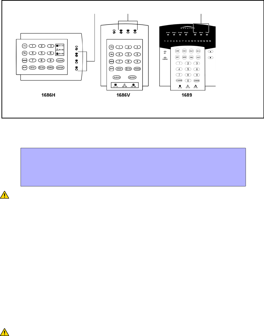
Configuring the 1686H, 1686V and 1689 Keypads (V2.0 or higher)
The keypad’s zone number, EOL definition and anti-tamper switch are programmed through the keypad’s programming
mode. To do so:
PLEASE NOTE: After two minutes, the keypad exits programming mode.
Key [1] - Keypad Zone Selection
Key [1] determines whether the keypad’s zone is Keypad Zone 1 or Keypad Zone 2. When key [1] is OFF (not illuminated),
the keypad’s zone is Keypad Zone 1. When key [1] is ON (illuminated), the keypad’s zone is Keypad Zone 2. Refer to the
Zone Recognition Table on page 6 for more information.
Key [1] OFF - Keypad Zone 1 (default)
Key [1] ON - Keypad Zone 2
Key [2] - EOL Definition
Key [2] determines the keypad zone’s EOL definition. When key [2] is OFF (not illuminated), EOL is disabled and the keypad
zone uses the on-board EOL resistor. When key [2] is ON (illuminated), EOL is enabled and the keypad zone requires that an
external EOL resistor be connected (refer to Spectra 1759MG PCB Layout on page 38 for more details).
Key [2] OFF - EOL disabled
Key [2] ON - EOL enabled (default)
Key [3] - On-Board Tamper
Key [3] enables or disables the keypad’s on-board anti-tamper switch. When key [3] is OFF (not illuminated), the anti-tamper
switch is disabled. When key [3] is ON (illuminated), the anti-tamper switch is enabled.
Key [3] OFF - On-board anti-tamper switch disabled
Key [3] ON - On-board anti-tamper switch enabled
PLEASE NOTE: The keypad can be ordered with or without an anti-tamper switch. If the keypad has no anti-
tamper switch, key [3] will be OFF by default. If the keypad has an anti-tamper switch, key [3] will be ON by default.
How Do I Configure The Keypad?
1) Press [ENTER]
2) Enter your [INSTALLER CODE] (default: 0000 / 000000)
3) Press the [PG] (1686H/V) / [FNC1] (1689) key and hold it for 3 seconds.
4) Press the desired key ([1] to [3]. See below)
5) Press [ENTER] to exit programming mode
To access the Data Display Mode, press the [ENTER] key after entering a section and before entering any data. The
three LEDs as indicated below will begin to flash indicating that you are in the Data Display Mode.
Each time the [ENTER] key is pressed, the keypad will display the next digit in the current section and will continue
through all the following sections one digit at a time without changing the programmed values. Not available for
sections using the Multiple Feature Select Method. Press the [CLEAR] key at any time to exit the Data Display Mode.

Spectra 1759MG - 6 - Programming Guide
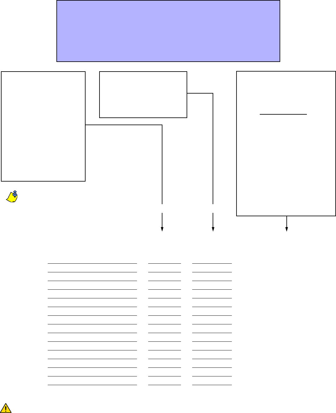
Zone Programming
When programming zones, the zone assignments are dependent on where the detection devices are connected to in the
system (see Zone Recognition Table). In installations that require using mostly the expansion inputs, refer to Reassign
Keypad Zone 2 (see section [126] option [7] on page 12) and Reassign zones to expansion inputs (see section [126] option
[8] on page 12).
.
Do not assign inputs from different modules to the same expansion input.
Zone Recognition Table
Option [7]: OFF
Option [8]: OFF Option [7]: ON
Option [8]: OFF Option [7]: OFF
Option [8]: ON Option [7]: ON
Option [8]: ON
Control Panel
Input 1 = Zone 1 Zone 1 Zone 1 Zone 1
Input 2 = Zone 2 Zone 2 Zone 2 Zone 2
Input 3 = Zone 3 Zone 3 N/A N/A
Input 4 = Zone 4 Zone 4 N/A N/A
Input 5 = Zone 5 Zone 5 N/A N/A
Keypad
Zone 1 = Zone 6 Zone 6 Zone 3 Zone 3
Zone 2 = Zone 7 N/A Zone 4 N/A
Expansion
Input 1 = Zone 8 Zone 7 Zone 5 Zone 4
Input 2 = Zone 9 Zone 8 Zone 6 Zone 5
Input 3 = Zone 10 Zone 9 Zone 7 Zone 6
Input 4 = Zone 11 Zone10 Zone 8 Zone 7
Input 5 = Zone 12 Zone 11 Zone 9 Zone 8
Input 6 = Zone 13 Zone 12 Zone 10 Zone 9
Input 7 = Zone 14 Zone 13 Zone 11 Zone 10
Input 8 = Zone 15 Zone 14 Zone 12 Zone 11
= not displayed on 10-Zone LED Keypads
Option [7] = Reassign Keypad Zone 2
Option [8] = Reassign zones to expansion inputs
Spectra 1759MG - 7 - Programming Guide
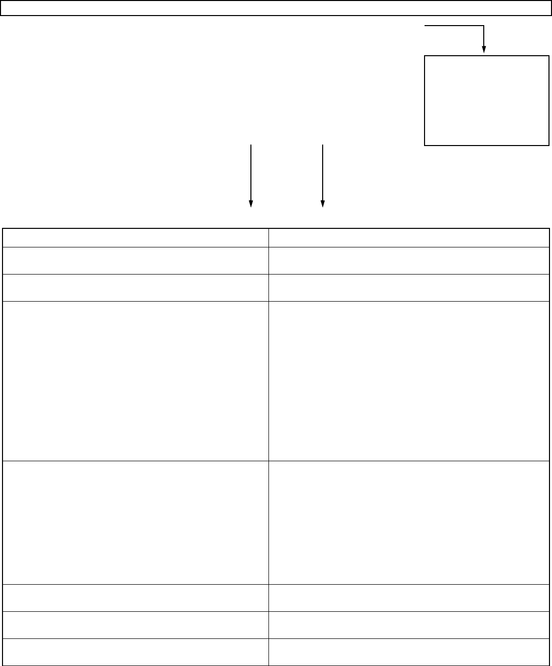
Only the control panel’s on-board inputs can be defined as a Fire, Delayed Fire or a Keyswitch zone.
The on-board zones are zones 01 to 05. To program a wireless fire zone, refer to Programming a Wireless Fire
Zone on page 36.
How Do I Program the Zones?
1) Press the [ENTER] key
2) Enter the [INSTALLER CODE] (Default: 0000 / 000000)
3) Enter 3-digit [SECTION]
4) Enter one digit from the Zone Definition table (see page 7)
5) Enter one digit from the Partition Assignment table (see page 7)
6) Select one or more options from the Zone Options table (see page 7)
7) Press the [ENTER] key
Section Description Zone
Definition Partition
Assignment Zone Options
[001]
= Zone 01: 1 2 3 4 5 6 7 8
[002]
= Zone 02: 1 2 3 4 5 6 7 8
[003]
= Zone 03: 1 2 3 4 5 6 7 8
[004]
= Zone 04: 1 2 3 4 5 6 7 8
[005]
= Zone 05: 1 2 3 4 5 6 7 8
[006]
= Zone 06: 1 2 3 4 5 6 7 8
[007]
= Zone 07: 1 2 3 4 5 6 7 8
[008]
= Zone 08: 1 2 3 4 5 6 7 8
[009]
= Zone 09: 1 2 3 4 5 6 7 8
[010]
= Zone 10: 1 2 3 4 5 6 7 8
[011]
= Zone 11: 1 2 3 4 5 6 7 8
[012]
= Zone 12: 1 2 3 4 5 6 7 8
[013]
= Zone 13: 1 2 3 4 5 6 7 8
[014]
= Zone 14: 1 2 3 4 5 6 7 8
[015]
= Zone 15: 1 2 3 4 5 6 7 8
Defaults =
Empty Partition 1 1 and 2
ON
[FORCE] key = empty
Zone Definition
Empty -
Zone Disabled
1 -
Entry Delay 1
2 -
Entry Delay 2
3 -
Follow
4 -
Instant
5 -
24Hr Burglary
6 -
24Hr Buzzer
Additional definitions for
on-board terminals:
7 -
Keyswitch
8 -
Fire 24Hr
9 -
Delayed Fire 24Hr
Partition Assignment
Empty -
Zone Disabled
1 -
Partition 1
2 -
Partition 2
3 -
Both Partitions
Zone Options
1 -
Auto Zone Shutdown
2 -
Bypass Enabled
3 -
Stay Zone
4 - 5 -
Zone Alarm Type
off off Audible alarm (steady)
off on Audible alarm (pulsed)
on off Silent alarm
on on Generates a report only
6 -
Intellizone
7 -
Delay alarm transmission
8 -
Force Zone
Keyswitch Options
1 -
off = Maintained
on = Momentary
2 -
off = Regular Arm
on = Stay Arm
Second DigitFirst Digit
Spectra 1759MG - 8 - Programming Guide
System Timers
Section # Decimal Value (000 to 255) Description Default
[050]
___/___/___ x 10 msec. ZONE SPEED (ZONE 1) 600 msec.
[051]
___/___/___ x 10 msec. ZONE SPEED (ZONE 2) 600 msec.
[052]
___/___/___ x 10 msec. ZONE SPEED (ZONE 3) 600 msec.
[053]
___/___/___ x 10 msec. ZONE SPEED (ZONE 4) 600 msec.
[054]
___/___/___ x 10 msec. ZONE SPEED (ZONE 5) 600 msec.
[055]
___/___/___ x 10 msec. ZONE SPEED (ZONE 6) 600 msec.
[056]
___/___/___ x 10 msec. ZONE SPEED (ZONE 7) 600 msec.
[057]
___/___/___ x 10 msec. ZONE SPEED (ZONE 8) 600 msec.
[058]
___/___/___ x 10 msec. ZONE SPEED (ZONE 9) 600 msec.
[059]
___/___/___ x 10 msec. ZONE SPEED (ZONE 10) 600 msec.
[060]
___/___/___ x 10 msec. ZONE SPEED (ZONE 11) 600 msec.
[061]
___/___/___ x 10 msec. ZONE SPEED (ZONE 12) 600 msec.
[062]
___/___/___ x 10 msec. ZONE SPEED (ZONE 13) 600 msec.
[063]
___/___/___ x 10 msec. ZONE SPEED (ZONE 14) 600 msec.
[064]
___/___/___ x 10 msec. ZONE SPEED (ZONE 15) 600 msec.
[065]
FUTURE USE
[066]
___/___/___ seconds (000 = follow Deactivation Event) PGM1 TIMER 5 sec.
[067]
___/___/___ seconds (000 = follow Deactivation Event) PGM2 TIMER 5 sec.
[068]
___/___/___ seconds (000 = follow Deactivation Event) GLOBAL PGM TIMER 5 sec.
[069]
___/___/___ seconds ENTRY DELAY 1 45 sec.
[070]
___/___/___ seconds ENTRY DELAY 2 45 sec.
[071]
___/___/___ seconds EXIT DELAY 1 30 sec.
[072]
___/___/___ seconds EXIT DELAY 2 30 sec.
[073]
___/___/___ minutes (000 = no bell on alarm) BELL CUT-OFF TIMER (PARTITION 1) 4 min.
[074]
___/___/___ minutes (000 = no bell on alarm) BELL CUT-OFF TIMER (PARTITION 2) 4 min.
[075]
___/___/___ x 15 minutes (000 = disabled) NO MOVEMENT TIMER (PARTITION 1) Disabled
[076]
___/___/___ x 15 minutes (000 = disabled) NO MOVEMENT TIMER (PARTITION 2) Disabled
[077]
___/___/___ seconds (minimum 10 sec.) ANSWERING MACHINE OVERRIDE DELAY Disabled
[078]
___/___/___ (000 = no answer, maximum = 15 rings) NUMBER OF RINGS 8 rings
[079]
___/___/___ x 2 sec. (minimum 32 sec.) TLM FAIL TIMER 32 sec.
[080]
___/___/___ seconds DELAY ALARM TRANSMISSION Disabled
[081]
___/___/___ (000 = 16, maximum = 16) MAXIMUM DIALING ATTEMPTS 8 attempts
[082]
___/___/___ seconds DELAY BETWEEN ATTEMPTS 20 sec.
[083]
___/___/___ seconds PAGER DELAY 5 sec.
[084]
___/___/___ seconds (minimum 10 sec.) INTELLIZONE DELAY 48 sec.
[085]
___/___/___ seconds RECENT CLOSING DELAY No delay
[086]
___/___/___ minutes POWER FAILURE REPORT DELAY 15 min.
[087]
___/___/___ days (000 = disabled) AUTO TEST REPORT Disabled
[088]
___/___/___ 000 to 127 = +1 to +127 seconds
128 to 255 = -1 to -127 seconds
CLOCK ADJUST Disabled
[089]
___/___/___ (000 = disabled, maximum = 15) AUTO ZONE SHUTDOWN COUNTER 5
[090]
___/___/___ minutes (000 = disabled) RECYCLE ALARM DELAY Disabled
[091]
___/___/___ (000 = disabled) RECYCLE ALARM COUNTER Disabled
[092]
___/___/___ attempts before locking (000 = disabled) KEYPAD LOCKOUT Disabled
[093]
___/___/___ minutes (000 = disabled) KEYPAD LOCKOUT DELAY Disabled
[094]
___/___/___ seconds (000 = disabled) PANIC LOCKOUT TIMER Disabled
[095] ___/___/___ days (000 = disabled) CLOSING DELINQUENCY TIMER (PARTITION 1) Disabled
[110]
___/___ : ___/___ hours (00 to 23) : minutes (00 to 59)
___/___ : ___/___ hours (00 to 23) : minutes (00 to 59)
___/___ : ___/___ hours (00 to 23) : minutes (00 to 59)
AUTO TEST REPORT (TIME OF DAY)Disabled
[111]
AUTO-ARM TIME (PARTITION 1) Disabled
[112]
AUTO-ARM TIME (PARTITION 2) Disabled
Spectra 1759MG - 9 - Programming Guide
Programmable Outputs
Each PGM Deactivation event can be used as another start (activation) event if their respective PGM timer (see sections
[066] to [068]) is programmed with a value other than 000.
Example: section [120] = 05 03 02: this means PGM1 will activate whenever partition 2 is Stay Armed.
Section # Event Group # Sub-Group # Partition #
[120]
PGM 1 PGM Activation Event ___/___ ___/___ ___/___
[121]
PGM 1 PGM Deactivation Event ___/___ ___/___ ___/___
[122]
PGM 2 PGM Activation Event ___/___ ___/___ ___/___
[123]
PGM 2 PGM Deactivation Event ___/___ ___/___ ___/___
[124]
Global PGM Activation Event ___/___ ___/___ ___/___
[125]
Global PGM Deactivation Event
Used to activate PGMs on
expansion modules & LCD keypads.
___/___ ___/___ ___/___
Event Group # Sub-Group #
00 = Zone OK 01 to 15 = Zones 1 to 15
99 = Any Zone
01 = Zone Open 01 to 15 = Zones 1 to 15
99 = Any Zone
02 = Partition Status 00 = System not ready (Partition 1 only)
01 = System ready (Partition 1 only)
02 = Steady Alarm in Partition
03 = Pulsed Alarm in Partition
04 = Pulsed or Steady Alarm in Partition
05 = Alarm in Partition Restored
06 = Bell Squawk Activated (Partition 1 only)
07 = Bell Squawk Deactivated (Partition 1 only)
08 = Ground start (Partition 1 only)
09 = Disarm Partition
10 = Arm Partition
11 = Entry Delay (breach when system is armed)
99 = Any Sub-Group
05 = Non-Reportable Events 00 = Telephone Line Trouble (Partition 1 only)
01 = [PG] or [FNC1] key was pressed (Partition 1 only). This
option can also be used to reset smoke detectors.
02 = Instant Arming
03 = Stay Arming
04 = Force Arming
05 = Fast Exit (Force & Regular Only)
06 = PC Fail to Communicate (Partition 1 only)
07 = Midnight (Partition 1 only)
99 = Any Sub-Group (Partition 1 only, except 02 to 05)
06 = Arm/Disarm with Remote Control 01 to 08 = Remote Controls 1 to 8
99 = Any Remote Control
07 = Button Pressed on Remote
(see button option “B” on page 25) 01 to 08 = Remote Controls 1 to 8
99 = Any Remote Control
08 = Button Pressed on Remote
(see button option “C” on page 25) 01 to 08 = Remote Controls 1 to 8
99 = Any Remote Control
01 = Partition 1
02 = Partition 2
99 = Any Partition
The Sub-Groups proceeded by
“(Partition 1)” cannot be
assigned to activate Partition 2.

Spectra 1759MG - 10 - Programming Guide
09 = Button Pressed on Remote
(see button option “D” on page 25) 01 to 08 = Remote Controls 1 to 8
99 = Any Remote Control
10 = Bypass Programming 01 to 48 = User Code Numbers 001 to 048
99 = Any User Code
11 = User Activated PGM 01 to 48 = User Code Numbers 001 to 048 (Partition 1 only)
99 = Any User Code
12 = Zone with Delay Transmission Option Enabled is
Breached 01 to 15 = Zones 1 to 15
99 = Any Zone
13 = Arm with User Code 01 to 48 = User Code Numbers 001 to 048
99 = Any User Code
14 = Special Arm 00 = Auto Arming (timed/no movement)
01 = Late to Close (Auto-Arming failed)
02 = No Movement Auto-Arming
03 = Partial Arming (Stay, Force, Instant, Bypass)
04 = One-Touch Arming
05 = Arm with WinLoad Software
07 = Closing Delinquency (Partition 1 only)
99 = Any Sub-Group
15 = Disarm with User Code 01 to 48 = User Code Numbers 001 to 048
99 = Any User Code
16 = Disarm After Alarm w/ User Code 01 to 48 = User Code Numbers 001 to 048
99 = Any User Code
17 = Cancel Alarm with User Code 01 to 48 = User Code Numbers 001 to 048
99 = Any User Code
18 = Special Disarm 00 = Cancel Auto Arm (timed/no movement)
01 = Disarm with WinLoad Software
02 = Disarm after alarm with WinLoad Software
03 = Cancel Alarm with WinLoad Software
99 = Any Sub-Group
19 = Zone Bypassed on Arming 01 to 15 = Zones 1 to 15
99 = Any Zone
20 = Zone in Alarm 01 to 15 = Zones 1 to 15
99 = Any Zone
21 = Fire Alarm 01 to 05 = Zones 1 to 5 (on-board inputs)
99 = Any Zone
22 = Zone Alarm Restore 01 to 15 = Zones 1 to 15
99 = Any Zone
23 = Fire Alarm Restore 01 to 05 = Zones 1 to 5 (on-board inputs)
99 = Any Zone
24 = Special Alarm 00 = Emergency Panic
01 = Auxiliary Panic
02 = Fire Panic
03 = Recent Closing
04 = Auto Zone Shutdown
05 = Duress Alarm
06 = Keypad Lockout
99 = Any Sub-Group
25 = Auto Zone Shutdown 01 to 15 = Zones 1 to 15
99 = Any Zone
26 = Zone Tamper 01 to 15 = Zones 1 to 15
99 = Any Zone
27 = Zone Tamper Restore 01 to 15 = Zones 1 to 15
99 = Any Zone
Event Group # Sub-Group #

Spectra 1759MG - 11 - Programming Guide
28 = System Trouble 01 = AC Loss: only after Power Failure Delay has elapsed
(Partition 1 only)
02 = Battery Failure (Partition 1 only)
03 = Auxiliary current overload (Partition 1 only)
04 = Bell current overload (Partition 1 only)
05 = Bell disconnected (Partition 1 only)
06 = Timer Loss (Partition 1 only)
07 = Fire Loop Trouble (Partition 1 only)
08 = Future Use
09 = Module Fault (Partition 1 only)
10 = Printer Fault (Partition 1 only)
11 = Fail to Communicate (Partition 1 only)
99 = Any Sub-Group (Partition 1 only)
29 = System Trouble Restore 00 = TLM restore (Partition 1 only)
01 = AC Loss restore (Partition 1 only)
02 = Battery Failure restore (Partition 1 only)
03 = Auxiliary current overload restore (Partition 1 only)
04 = Bell current overload restore (Partition 1 only)
05 = Bell disconnected restore (Partition 1 only)
06 = Timer Programmed (Partition 1 only)
07 = Fire Loop Trouble restore (Partition 1 only)
08 = Future Use
09 = Module Fault restore (Partition 1 only)
10 = Printer Fault restore (Partition 1 only)
11 = Fail to Communicate restore (Partition 1 only)
99 = Any Trouble Restore (Partition 1 only)
30 = Special Reporting 00 = System Power Up (Partition 1 only)
01 = Test Report (Partition 1 only)
02 = WinLoad Software Access (Partition 1 only)
03 = WinLoad Software Access finished (Partition 1 only)
04 = Installer enters programming mode (Partition 1 only)
05 = Installer exits programming mode (Partition 1 only)
99 = Any Sub-Group (Partition 1 only)
31 = Wireless Transmitter Supervision Loss 01 to 15 = Zones 1 to 15
99 = Any Zone
32 = Wireless Transmitter Supervision Loss Restore 01 to 15 = Zones 1 to 15
99 = Any Zone
33 = Arming with a Keyswitch 01 to 05 = Zones 1 to 5 (on-board inputs)
99 = Any Zone
34 = Disarming with a Keyswitch 01 to 05 = Zones 1 to 5 (on-board inputs)
99 = Any Zone
35 = Disarm after Alarm with a Keyswitch 01 to 05 = Zones 1 to 5 (on-board inputs)
99 = Any Zone
36 = Cancel Alarm with a Keyswitch 01 to 05 = Zones 1 to 5 (on-board inputs)
99 = Any Zone
37 = Wireless Transmitter Low Battery 01 to 15 = Zones 1 to 15
99 = Any Zone
38 = Wireless Transmitter Low Battery Restore 01 to 15 = Zones 1 to 15
99 = Any Zone
Event Group # Sub-Group # Partition #
80 = PGM follows Clock (APR3-PGM4 only) HH = hour according to 24hr. clock MM = minutes according to 24hr. clock
Event Group # Sub-Group #

Spectra 1759MG - 12 - Programming Guide
System Options
Bold = Default Setting
* Reassign Keypad Zone 2 and Reassign zones to expansion inputs change the zone numbering to increase the number of
expansion inputs that can be displayed on 10-Zone LED Keypads. Refer to the Zone Recognition Table on page 6 and the
Spectra 1759MG Reference & Installation Manual for details.
Section [126]: General Options
Option
OFF ON
[1]
Confidential Mode N Disabled N Enabled
[2]
To exit Confidential Mode N Enter Access Code N Press a Key
[3]
Confidential Mode timer N 2 minutes N 5 seconds
[4]
PGM1 normal state N Normally Open (N.O.) N Normally Closed (N.C.)
[5]
PGM2 normal state N Normally Open (N.O.) N Normally Closed (N.C.)
[6]
Global PGM normal state N Normally Open (N.O.) N Normally Closed (N.C.)
[7]
Reassign Keypad Zone 2* N Disabled N Enabled
[8]
Reassign zones to expansion inputs* N Disabled N Enabled
Section [127]: General Options
Option
OFF ON
[1]
Partitioning N Disabled N Enabled
[2]
Access code length N 6-digits N 4-digits
[3]
Keypad audible trouble warning N Disabled N Enabled
[4]
Lock System Master Code N Disabled N Enabled
[5]
Battery charge current N 350mA N 700mA
[6]
User Code 048 is a Duress Code N Disabled N Enabled
[7]
Alarm relay follows N Bell Output N Global PGM
[8]
Future use N N/A N N/A
Section [128]: General Options
Option
OFF ON
[1]
Panic 1: keys [1] & [3] N Disabled N Enabled
[2]
Panic 2: keys [4] & [6] N Disabled N Enabled
[3]
Panic 3: keys [7] & [9] N Disabled N Enabled
[4]
Panic 1: silent or audible N Silent N Audible
[5]
Panic 2: silent or audible N Silent N Audible
[6]
Panic 3: silent or fire N Silent N Fire
[7]
Keypad 1 tamper supervision N Disabled N Enabled
[8]
Keypad 2 tamper supervision N Disabled N Enabled
Section [129]: General Options
Option
OFF ON
[1]
PGM2 output activation option N Steady N Pulse (flash)
[2]
PGM2 pulse once every 30 sec. if system armed N Disabled N Enabled
[3]
PGM2 pulse on Arm, twice on Disarm N Disabled N Enabled
[4]
ZX4 & ZX8 zone expansion module supervision N Disabled N Enabled
[5]
Future use N N/A N N/A
[6]
Wireless module low battery supervision N Disabled N Enabled
[7]
4-PGM Output Module supervision (APR3-PGM4) N Disabled N Enabled
[8]
Printer Module supervision (APR3-PRT1) N Disabled N Enabled

Spectra 1759MG - 13 - Programming Guide
Bold
= Default Setting
* This option cannot be done using a keyswitch. Force arming is not supported by keyswitches.
Section [130]: Arming/Disarming Options
Option
OFF ON
[1]
One-touch Regular Arming N Disabled N Enabled
[2]
One-touch Stay Arming N Disabled N Enabled
[3]
One-touch Force Arming N Disabled N Enabled
[4]
One-touch bypass programming N Disabled N Enabled
[5]
Restrict arming on battery failure N Disabled N Enabled
[6]
Restrict arming on Tamper failure N Disabled N Enabled
[7]
Bell Squawk on Arm/Disarm with keypad N Disabled N Enabled
[8]
Beep on exit delay N Disabled N Enabled
Section [131]: Arming/Disarming Options
Option
OFF ON
[1]
Report Disarming N Always N Only after alarm
[2]
Regular Arming switches to Force Arming * N Disabled N Enabled
[3]
Bell Squawk on Arm/Disarm with remote control
(must be enabled for UL installations) N Disabled N Enabled
[4]
No exit delay when Arming with a remote control N Disabled N Enabled
[5]
No exit delay beeps and no Bell Squawk when
Stay Arming N Disabled N Enabled
[6]
Restrict arming on wireless transmitter
supervision loss N Disabled N Enabled
[7]
Generate supervision loss if detected on
bypassed wireless zone N Yes N No
[8]
Future Use N N/A N N/A
Section [132]: Zone Options
Option
OFF ON
[1]&[2]
N see table
N see table N see table
N see table
[3]
Generate tamper if detected on bypassed zone N Yes N No
[4]
EOL (end-of-line) resistors N No EOL N Use EOL Resistors
[5]
Future use N N/A N N/A
[6]
Report zone restore N On Bell Cut-off N On Zone Closure
[7]&[8]
N see table
N see table N see table
N see table
Tamper Recognition Options
[1] [2]
OFF OFF Disabled (default)
OFF ON When disarmed: GENERATES TROUBLE ONLY
When armed: Follows Zone Alarm Types
ON OFF When disarmed: GENERATES SILENT ALARM
When armed: Follows Zone Alarm Types
ON ON When disarmed: GENERATES AUDIBLE ALARM
When armed: Follows Zone Alarm Types
Wireless Transmitter Supervision Options
[7] [8]
OFF OFF Disabled (default)
OFF ON When disarmed: GENERATES TROUBLE ONLY
When armed: Follows Zone Alarm Types
ON OFF When disarmed: GENERATES SILENT ALARM
When armed: Follows Zone Alarm Types
ON ON When disarmed: GENERATES AUDIBLE ALARM
When armed: Follows Zone Alarm Types

Spectra 1759MG - 14 - Programming Guide
Bold = Default Setting
Section [133]: Partition 1 Options
Option
OFF ON
[1]
Auto-arm on time N Disabled N Enabled
[2]
Auto-arm on no movement N Disabled N Enabled
[3]
Auto Arming = Regular or Stay N Regular Arming N Stay Arming
[4]
Switch to Stay Arming if no entry delay is opened N Disabled N Enabled
[5]
Stay Arming with Delay Partition 1 (Delay = [070]) N Disabled N Enabled
[6] to [8]
Future use N N/A N N/A
Section [134]: Partition 2 Options
Option
OFF ON
[1]
Auto-arm on time N Disabled N Enabled
[2]
Auto-arm on no movement N Disabled N Enabled
[3]
Auto Arming = Regular or Stay N Regular Arming N Stay Arming
[4]
Switch to Stay Arming if no entry delay is opened N Disabled N Enabled
[5]
Stay Arming with Delay Partition 2 (Delay = [070]) N Disabled N Enabled
[6] to [8]
Future use N N/A N N/A
Section [135]: Dialer Options
Option
OFF ON
[1] & [2]
N see table
N see table N see table
N see table
[3]
Reporting (Dialer) N Disabled N Enabled
[4]
Dialing method N Pulse Dialing N Tone (DTMF) Dialing
[5]
Pulse ratio N 1:2 N 1:1.5
[6]
If armed, activate bell output on Com. Failure N Disabled N Enabled
[7] & [8]
Future use N N/A N N/A
Section [136]: Dialer Options
Option
OFF ON
[1]
Call back WinLoad N Disabled N Enabled
[2]
Automatic event buffer transmission N Disabled N Enabled
[3]
Contact I.D. report codes N Programmable N All Codes (automatic)
[4]
Alternate dial N Disabled N Enabled
[5]
If no dial tone is present N Continue after 4 sec. N Hang-up after 16 sec.
[6] & [7]
N see table
N see table N see table
N see table
[8]
Pager Format Transmission Options N Transmit report code
after Pager delay N Transmit report code
immediately
Telephone Line Monitoring (TLM) Options
[1] [2]
OFF OFF TLM Disabled (default)
OFF ON TLM generates a trouble if armed
ON OFF TLM generates an audible alarm if armed
ON ON Silent alarms become audible
Pager Reporting Format Dialer Options
[6] [7]
OFF OFF 1 call to pager or cellular telephone (default)
OFF ON 2 calls to pager or cellular telephone
ON OFF 3 calls to pager or cellular telephone
ON ON 4 calls to pager or cellular telephone

Spectra 1759MG - 15 - Programming Guide
Bold = Default Setting
Communication Settings
Section [137]: Event Call Direction
Option
OFF ON
[1]
Call Telephone #1 for Arming/Disarming Report Codes N Disabled N Enabled
[2]
Call Telephone #2 for Arming/Disarming Report Codes N Disabled N Enabled
[3]
Call Telephone #1 for Alarm/Restore Report Codes N Disabled N Enabled
[4]
Call Telephone #2 for Alarm/Restore Report Codes N Disabled N Enabled
[5]
Call Telephone #1 for Tamper/Restore Report Codes N Disabled N Enabled
[6]
Call Telephone #2 for Tamper/Restore Report Codes N Disabled N Enabled
[7] & [8]
Future use N N/A N N/A
Section [138]: Event Call Direction
Option
OFF ON
[1]
Call Telephone #1 for Trouble/Restore Report Codes N Disabled N Enabled
[2]
Call Telephone #2 for Trouble/Restore Report Codes N Disabled N Enabled
[3]
Call Telephone #1 for Special Report Codes N Disabled N Enabled
[4]
Call Telephone #2 for Special Report Codes N Disabled N Enabled
[5] to [8]
Future use N N/A N N/A
Section #
[140] ___ / ___
TEL1 TEL2
REPORTING FORMATS
1 = ADEMCO SLOW (1400HZ, 1900HZ, 10BPS)
2 = SILENT KNIGHT FAST (1400HZ, 1900HZ, 20BPS)
3 = SESCOA (2300HZ, 1800HZ, 20BPS)
4 = ADEMCO EXPRESS (DTMF 4+2)
5 = ADEMCO CONTACT ID (DEFAULT) see option [3] in section [136] on page 14
6 = PAGER FORMAT
If Hexadecimals (0 to FF) are used to program the report codes, verify that the pager also supports
Hexadecimals. If the pager does not support Hexadecimals, use only the digits 0 to 9.
[141] ___/___/___/___ PANEL IDENTIFIER (WINLOAD SOFTWARE)
[142] ___/___/___/___ PC PASSWORD (WINLOAD SOFTWARE)
[143] ___/___/___/___ PARTITION ACCOUNT NUMBER 1 (For less than 4 digits, use the [FORCE] key to enter blanks.)
[144] ___/___/___/___ PARTITION ACCOUNT NUMBER 2 (For less than 4 digits, use the [FORCE] key to enter blanks.)
[150] __/__/__/__/__/__/__/__/__/__/__/__/__/__/__/__/__/__/__/__/__/__/__/__/__/__/__/__/__/__/__/__
PC TELEPHONE NUMBER FOR WINLOAD SOFTWARE (32-digits, if less than 32 press [ENTER] to accept)
[151] __/__/__/__/__/__/__/__/__/__/__/__/__/__/__/__/__/__/__/__/__/__/__/__/__/__/__/__/__/__/__/__
CENTRAL STATION TELEPHONE OR PAGER NUMBER 1 (32-digits, if less than 32 press [ENTER] to accept)
[152] __/__/__/__/__/__/__/__/__/__/__/__/__/__/__/__/__/__/__/__/__/__/__/__/__/__/__/__/__/__/__/__
CENTRAL STATION TELEPHONE OR PAGER NUMBER 2 (32-digits, if less than 32 press [ENTER] to accept)
[153] __/__/__/__/__/__/__/__/__/__/__/__/__/__/__/__/__/__/__/__/__/__/__/__/__/__/__/__/__/__/__/__
BACK UP TELEPHONE NUMBER (32-digits, if less than 32 press [ENTER] to accept)
Special Keys for Telephone Numbers
[STAY] = * [MEM] = Switch from pulse to tone dialing or vice versa [FORCE] = Delete current digit
[BYP] = # [TBL] or [TRBL] = 4-second pause [PG] or [FNC1] = Inserts Blank Space
Spectra 1759MG - 16 - Programming Guide
Report Codes
Ademco Slow, Silent Knight, SESCOA, Ademco Express and Pager Formats: Enter the desired 1- or 2-digit hex-value
(0-F or 00-FF). Ademco “Programmable” Format: Enter the desired 2-digit hex values from the “Ademco Report Code List
- Programmable” (see Appendix A on page 30). Also Note that entering FF will set the report code to the default Ademco
Report Code. Ademco “All Codes” Format: The control panel automatically generates report codes from the “Ademco
Report Code List - All Codes” (see Appendix B on page 31).
Arming Report Codes
[160]___/___Access Code 01
___/___Access Code 02
___/___Access Code 03
___/___Access Code 04
[165]___/___Access Code 21
___/___Access Code 22
___/___Access Code 23
___/___Access Code 24
[170]___/___Access Code 41
___/___Access Code 42
___/___Access Code 43
___/___Access Code 44
[161]___/___Access Code 05
___/___Access Code 06
___/___Access Code 07
___/___Access Code 08
[166]___/___Access Code 25
___/___Access Code 26
___/___Access Code 27
___/___Access Code 28
[171]___/___Access Code 45
___/___Access Code 46
___/___Access Code 47
___/___Access Code 48
[162]___/___Access Code 09
___/___Access Code 10
___/___Access Code 11
___/___Access Code 12
[167]___/___Access Code 29
___/___Access Code 30
___/___Access Code 31
___/___Access Code 32
Special Arming Codes
[163]___/___Access Code 13
___/___Access Code 14
___/___Access Code 15
___/___Access Code 16
[168]___/___Access Code 33
___/___Access Code 34
___/___Access Code 35
___/___Access Code 36
[172]___/___Auto-Arming
___/___Late to Close
___/___No Movement
___/___Partial Arming
[164]___/___Access Code 17
___/___Access Code 18
___/___Access Code 19
___/___Access Code 20
[169]___/___Access Code 37
___/___Access Code 38
___/___Access Code 39
___/___Access Code 40
[173]___/___Quick Arming
___/___Arming via PC
___/___Keyswitch Arming
___/___Closing Delinquency
Disarming Report Codes
[174]___/___Access Code 01
___/___Access Code 02
___/___Access Code 03
___/___Access Code 04
[179]___/___Access Code 21
___/___Access Code 22
___/___Access Code 23
___/___Access Code 24
[184]___/___Access Code 41
___/___Access Code 42
___/___Access Code 43
___/___Access Code 44
[175]___/___Access Code 05
___/___Access Code 06
___/___Access Code 07
___/___Access Code 08
[180]___/___Access Code 25
___/___Access Code 26
___/___Access Code 27
___/___Access Code 28
[185]___/___Access Code 45
___/___Access Code 46
___/___Access Code 47
___/___Access Code 48
[176]___/___Access Code 09
___/___Access Code 10
___/___Access Code 11
___/___Access Code 12
[181]___/___Access Code 29
___/___Access Code 30
___/___Access Code 31
___/___Access Code 32
Special Disarming Codes
[177]___/___Access Code 13
___/___Access Code 14
___/___Access Code 15
___/___Access Code 16
[182]___/___Access Code 33
___/___Access Code 34
___/___Access Code 35
___/___Access Code 36
[186]___/___Cancel Auto-Arm
___/___Disarming via PC
___/___Keyswitch Disarm
___/___N/A
[178]___/___Access Code 17
___/___Access Code 18
___/___Access Code 19
___/___Access Code 20
[183]___/___Access Code 37
___/___Access Code 38
___/___Access Code 39
___/___Access Code 40
Spectra 1759MG - 17 - Programming Guide
Alarm Report Codes
Alarm Restore Special
[187]___/___Zone 01
___/___Zone 02
___/___Zone 03
___/___Zone 04
[191]___/___Zone 01
___/___Zone 02
___/___Zone 03
___/___Zone 04
[195]___/___Emergency Panic
___/___Auxiliary Panic
___/___Fire Panic
___/___Recent Closing
[188]___/___Zone 05
___/___Zone 06
___/___Zone 07
___/___Zone 08
[192]___/___Zone 05
___/___Zone 06
___/___Zone 07
___/___Zone 08
[196]___/___Zone Shutdown
___/___Duress
___/___Keypad Lockout
___/___N/A
[189]___/___Zone 09
___/___Zone 10
___/___Zone 11
___/___Zone 12
[193]___/___Zone 09
___/___Zone 10
___/___Zone 11
___/___Zone 12
[190]___/___Zone 13
___/___Zone 14
___/___Zone 15
___/___N/A
[194]___/___Zone 13
___/___Zone 14
___/___Zone 15
___/___N/A
Tamper Report Codes
[197]
Trouble
___/___Zone 01
___/___Zone 02
___/___Zone 03
___/___Zone 04
[200]___/___Zone 13
___/___Zone 14
___/___Zone 15
___/___N/A
[203]___/___Zone 09
___/___Zone 10
___/___Zone 11
___/___Zone 12
[198]___/___Zone 05
___/___Zone 06
___/___Zone 07
___/___Zone 08
[201]
Restore
___/___Zone 01
___/___Zone 02
___/___Zone 03
___/___Zone 04
[204]___/___Zone 13
___/___Zone 14
___/___Zone 15
___/___N/A
[199]___/___Zone 09
___/___Zone 10
___/___Zone 11
___/___Zone 12
[202]___/___Zone 05
___/___Zone 06
___/___Zone 07
___/___Zone 08
System Trouble Report Codes
System Trouble Restore Special
[205]___/___N/A
___/___AC Failure
___/___Battery Failure
___/___Auxiliary Supply
[208]___/___TLM
___/___AC Failure
___/___Battery Failure
___/___Auxiliary Supply
[211]___/___Cold Start (Shutdown)
___/___Test Report
___/___N/A
___/___PC Exit
[206]___/___Bell Output Overload
___/___Bell Output Disconnect
___/___Timer Loss
___/___Fire Loop Trouble
[209]___/___Bell Output Overload
___/___Bell Output Disconnect
___/___Timer Loss
___/___Fire Loop Trouble
[212]___/___Installer In
___/___Installer Out
___/___N/A
___/___N/A
[207]___/___Wireless Low Battery
___/___Module Fault
___/___Printer Fault
___/___Fail to Communicate
[210]___/___Wireless Low Battery
___/___Module Fault
___/___Printer Fault
___/___Fail to Communicate
[213]___/___TX Supervision Loss
___/___TX Supervision Restore
___/___N/A
___/___N/A

Spectra 1759MG - 18 - Programming Guide
System Settings
User Code Options
System Master Code arms or disarm partitions using any arming method and can create, modify or delete any User Access
Code. Only the System Master Code can modify or delete User Access Codes assigned to both partitions.
Master Code 1 is permanently assigned to partition 1 and can be used to create, modify or delete User Access Codes that
are assigned to partition 1.
Master Code 2 is permanently assigned to partition 2 (except when partitioning is disabled, Master Code 2 will be assigned
to partition 1) and can be used to create, modify or delete User Access Codes that are assigned to the same partition.
Section # Description
[280] ___/___:___/___ SYSTEM REAL TIME CLOCK (HH:MM)
[281] ___/___/___/___/___/___ INSTALLER CODE, DEFAULT: 0000 / 000000
[282] ___/___/___ INSTALLER CODE LOCK, DEFAULT: 000 (147 TO LOCK, 000 TO UNLOCK)
[301] ___/___/___/___/___/___ SYSTEM MASTER CODE, DEFAULT: 1234 / 123456
Default for all user codes is options
[1]
,
[3]
and
[4]
ON.
ON = Option Enabled
OFF = Option Disabled
[1]
ON = Partition 1 Access
[2]
ON = Partition 2 Access
[3]
ON = Bypass Programming
[4]
ON = Stay Arming
[5]
ON = Force Arming
[6]
ON = Arm Only
[7]
ON = PGM Activation Only
[8]
ON = Future Use
Section # User Code Options (ON/OFF)Section User Code Options (ON/OFF)
[302] Master Code 1 1 2 3 4 5 6 7 8 [325] User Code 025 1 2 3 4 5 6 7 8
[303] Master Code 2 1 2 3 4 5 6 7 8 [326] User Code 026 1 2 3 4 5 6 7 8
[304] User Code 004 1 2 3 4 5 6 7 8 [327] User Code 027 1 2 3 4 5 6 7 8
[305] User Code 005 1 2 3 4 5 6 7 8 [328] User Code 028 1 2 3 4 5 6 7 8
[306] User Code 006 1 2 3 4 5 6 7 8 [329] User Code 029 1 2 3 4 5 6 7 8
[307] User Code 007 1 2 3 4 5 6 7 8 [330] User Code 030 1 2 3 4 5 6 7 8
[308] User Code 008 1 2 3 4 5 6 7 8 [331] User Code 031 1 2 3 4 5 6 7 8
[309] User Code 009 1 2 3 4 5 6 7 8 [332] User Code 032 1 2 3 4 5 6 7 8
[310] User Code 010 1 2 3 4 5 6 7 8 [333] User Code 033 1 2 3 4 5 6 7 8
[311] User Code 011 1 2 3 4 5 6 7 8 [334] User Code 034 1 2 3 4 5 6 7 8
[312] User Code 012 1 2 3 4 5 6 7 8 [335] User Code 035 1 2 3 4 5 6 7 8
[313] User Code 013 1 2 3 4 5 6 7 8 [336] User Code 036 1 2 3 4 5 6 7 8
[314] User Code 014 1 2 3 4 5 6 7 8 [337] User Code 037 1 2 3 4 5 6 7 8
[315] User Code 015 1 2 3 4 5 6 7 8 [338] User Code 038 1 2 3 4 5 6 7 8
[316] User Code 016 1 2 3 4 5 6 7 8 [339] User Code 039 1 2 3 4 5 6 7 8
[317] User Code 017 1 2 3 4 5 6 7 8 [340] User Code 040 1 2 3 4 5 6 7 8
[318] User Code 018 1 2 3 4 5 6 7 8 [341] User Code 041 1 2 3 4 5 6 7 8
[319] User Code 019 1 2 3 4 5 6 7 8 [342] User Code 042 1 2 3 4 5 6 7 8
[320] User Code 020 1 2 3 4 5 6 7 8 [343] User Code 043 1 2 3 4 5 6 7 8
[321] User Code 021 1 2 3 4 5 6 7 8 [344] User Code 044 1 2 3 4 5 6 7 8
[322] User Code 022 1 2 3 4 5 6 7 8 [345] User Code 045 1 2 3 4 5 6 7 8
[323] User Code 023 1 2 3 4 5 6 7 8 [346] User Code 046 1 2 3 4 5 6 7 8
[324] User Code 024 1 2 3 4 5 6 7 8 [347] User Code 047 1 2 3 4 5 6 7 8
[348] User Code 048 1 2 3 4 5 6 7 8
Spectra 1759MG - 19 - Programming Guide
Reprogram All Modules
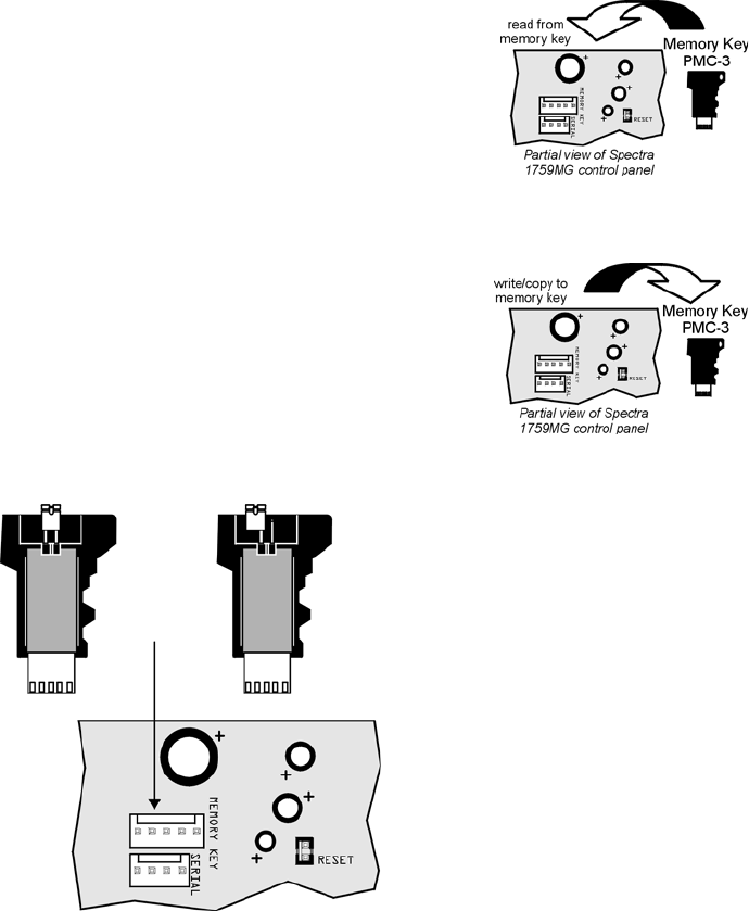
Paradox Memory Key (PMC-3)
Download to DESTINATION Control Panel
1) Remove AC and battery power from the control panel.
2) Insert the Memory Key onto the serial connector labelled KEY on the Spectra control panel to
which you wish to download the contents of the memory key to.
3) Re-apply AC and battery power.
4) Enter installer programming mode, enter section [900], then press [ENTER] to acknowledge.
5) When the keypad emits a “confirmation beep”, remove the Memory Key.
6) Enter section [750] to reprogram the modules with the information downloaded from the
Paradox Memory Key.
Copy to Memory Key from SOURCE Control Panel
1) Remove AC and battery power from the control panel.
2) Insert Memory Key onto the serial connector labelled KEY on the Spectra control panel that
you want to copy. Make sure the write protect jumper of the Memory Key is on.
3) Re-apply AC and battery power.
4) Enter installer programming mode, enter section [902], then press [ENTER] to acknowledge.
5) When the keypad emits a Confirmation Beep, remove the Memory Key. Remove the
Memory Key’s jumper if you do not wish to accidentally overwrite its contents.
[750]After removing an expansion module from the communication bus, the control panel keeps the module’s
programmed sections in memory. Therefore, if you add or replace a module you can re-program the module with the
settings saved in the control panel. To do so, enter section [750] and press [ENTER]. The keypads will beep twice
every second until the procedure is completed.
[900]DOWNLOAD FROM PARADOX MEMORY KEY TO DESTINATION CONTROL PANEL.
[902]COPY TO MEMORY KEY FROM SOURCE CONTROL PANEL.
Jumper ON =
Read from and/or write to
memory key
Paradox
Memory Key
PMC-3
Jumper OFF =
Write protected (read
from memory key only)
Insert Paradox Memory Key
onto the ‘MEMORY KEY’
connector.
Partial view of Spectra
1759MG control panel

Spectra 1759MG - 20 - Programming Guide
4-PGM Output Modules V2.0
Due to the APR3-PGM4’s Auto-recognition feature, it can be used with either the Spectra (V2.0 or higher), DGP-848 or
DGP-NE96 control panel. When connected to the bus, the APR3-PGM4 automatically detects which control panel it is
connected to and adjusts its internal communication parameters to function accordingly. Only one APR3-PGM4 can be
connected to each Spectra control panel.
Modules with the APR- prefix are compatible with Spectra (versions 2.0 and higher) and DGP-848. Modules with the
APR3- prefix are compatible with Spectra (versions 2.0 and higher), DGP-848 and DGP-NE96.
Bold = Default Setting
PGM Programming
Each PGM Deactivation event can be used as another activation event if their respective PGM timer (see sections [501] to
[504]) is programmed with a value other than 000. The APR3-PGM4 uses the same PGM events as the Spectra control
panel, please refer to Programmable Outputs on page 9.
Section # Decimal Value (000-255) Description Default Value
[501] ___/___/___ (000 = follow deactivation event) PGM1 TIMER 5 sec.
[502] ___/___/___ (000 = follow deactivation event) PGM2 TIMER 5 sec.
[503] ___/___/___ (000 = follow deactivation event) PGM3 TIMER 5 sec.
[504] ___/___/___ (000 = follow deactivation event) PGM4 TIMER 5 sec.
Section # Event Group # Sub-Group # Partition #
[505] PGM1 Activation Event ___/___ ___/___ ___/___
[506] PGM1 Deactivation Event ___/___ ___/___ ___/___
[507] PGM2 Activation Event ___/___ ___/___ ___/___
[508] PGM2 Deactivation Event ___/___ ___/___ ___/___
[509] PGM3 Activation Event ___/___ ___/___ ___/___
[510] PGM3 Deactivation Event ___/___ ___/___ ___/___
[511] PGM4 Activation Event ___/___ ___/___ ___/___
[512] PGM4 Deactivation Event ___/___ ___/___ ___/___
Section [500]: General Options
Option
OFF ON
[1] PGM1 Time Base Selection N Seconds N Minutes
[2] PGM2 Time Base Selection N Seconds N Minutes
[3] PGM3 Time Base Selection N Seconds N Minutes
[4] PGM4 Time Base Selection N Seconds N Minutes
[5] to [8] Future use N N/A N N/A

Spectra 1759MG - 21 - Programming Guide
Printer Module V2.0
Due to the APR3-PRT1’s Auto-recognition feature, it can be used with either the Spectra (V2.0 or higher), DGP-848 or
DGP-NE96 control panel. When connected to the bus, the APR3-PRT1 automatically detects which control panel it is
connected to and adjusts its internal communication parameters to function accordingly. Only one APR3-PRT1 can be
connected to each Spectra control panel.
Modules with the APR- prefix are compatible with Spectra (versions 2.0 and higher) and DGP-848. Modules with the
APR3- prefix are compatible with Spectra (versions 2.0 and higher), DGP-848 and DGP-NE96.
Bold = Default Setting
Section [550]: General Options
Option
OFF ON
[1] Assigned to Partition 1 N Disabled N Enabled
[2] Assigned to Partition 2 N Disabled N Enabled
[3] PGM normal state N Normally Open (N.O.) N Normally Closed (N.C.)
[4] Print Arming and disarming events N Disabled N Automatically
[5] Print Alarm and Alarm Restore events N Disabled N Automatically
[6] Print Tamper and Tamper Restore events N Disabled N Automatically
[7] Print Trouble and Trouble Restore events N Disabled N Automatically
[8] Print Special events N Disabled N Automatically
Section [551]: Automatic Zone Status Printing
Option
OFF ON
[1] Print status of Zone 1 N Disabled N Automatically
[2] Print status of Zone 2 N Disabled N Automatically
[3] Print status of Zone 3 N Disabled N Automatically
[4] Print status of Zone 4 N Disabled N Automatically
[5] Print status of Zone 5 N Disabled N Automatically
[6] Print status of Zone 6 N Disabled N Automatically
[7] Print status of Zone 7 N Disabled N Automatically
[8] Print status of Zone 8 N Disabled N Automatically
Section [552]: Automatic Zone Status Printing
Option
OFF ON
[1] Print status of Zone 9 N Disabled N Automatically
[2] Print status of Zone 10 N Disabled N Automatically
[3] Print status of Zone 11 N Disabled N Automatically
[4] Print status of Zone 12 N Disabled N Automatically
[5] Print status of Zone 13 N Disabled N Automatically
[6] Print status of Zone 14 N Disabled N Automatically
[7] Print status of Zone 15 N Disabled N Automatically
[8] N/A N N/A N N/A

Spectra 1759MG - 22 - Programming Guide
Bold = Default Setting
PGM Programming
The PGM Deactivation event can be used as another activation event if the PGM Timer (section [554]) is programmed with a
value other than 000. The APR3-PRT1 module uses the same PGM events as the Spectra control panel, please refer to
Programmable Outputs on page 9.
Section # Decimal Value (000-255) Description Default Value
[554] ___/___/___ seconds (000 = follow deactivation event) PGM1 TIMER 5s
Section # Event Group # Sub-Group # Partition #
[555] PGM1 Activation Event ___/___ ___/___ ___/___
[556] PGM1 Deactivation Event ___/___ ___/___ ___/___
Clock Programming
For example, to enter the date March 26, 2004 you would enter 2004 (year), 03 (month), and 26 (day).
Section # Value
[557] Year ___/___/___/___ Month ___/___ Day ___/___
Section [553]: Serial and Parallel Port Setup Options
Option
OFF ON
[1]
Serial port N Disabled N Enabled
[2]&[3]
N see table
N see table N see table
N see table
[4]
Parallel port N Disabled N Enabled
[5]
Off-line status ignored (parallel port only) N Disabled N Enabled
[6]
Paper empty status ignored (parallel port only) N Disabled N Enabled
[7]
Printer fault status ignored (parallel port only) N Disabled N Enabled
[8]
Printer busy status ignored (parallel port only) N Disabled N Enabled
Baud Rate Settings
[2] [3] APR-PRT1 APR3-PRT1
OFF OFF 1200 baud (default) 2400 baud (default)
ON OFF 2400 baud 9600 baud
OFF ON 9600 baud 19200 baud
ON ON 19200 baud 57600 baud

Spectra 1759MG - 23 - Programming Guide
Voice-assisted Arm/Disarm Bus Module V2.0
Due to InTouch’s Auto-recognition feature, it can be used with either the Spectra (V2.0 or higher), DGP-848 or DGP-NE96
control panels. When connected to the bus, InTouch automatically detects which control panel it is connected to and adjusts
its internal communication parameters to function accordingly. Only one InTouch can be connected to each Spectra control
panel.
APR3-ADM2 can also be programmed using the WinLoad Software. Refer to the WinLoad Online Help for more information.
Modules with the APR- prefix are compatible with Spectra (versions 2.0 and higher) and DGP-848. Modules with the
APR3- prefix are compatible with Spectra (versions 2.0 and higher), DGP-848 and DGP-NE96.
Section # Decimal Value (000-255) Description Default Value
[575] ___/___/___ rings (000 = disabled) NUMBER OF RINGS 8 rings
[576] ___/___/___ seconds (010-255, 000 = disabled) ANSWERING MACHINE OVERRIDE 000
[577] ___/___/___ seconds/minutes (000 = disabled) PGM TIMER 005
Bold = Default Setting
Section [578]: General Options
Option
OFF ON
[1]
Stand-alone Code length N 6-digits N 4-digits
[2]
Partitioned system N Disabled N Enabled
[3]
PGM output N Disabled N Enabled
[4]
PGM time in N Seconds N Minutes
[5] to [8]
Future use N N/A N N/A

Spectra 1759MG - 24 - Programming Guide
Wireless Features
Do not cut, bend or alter 1759MG’s antennae and ensure that electrical wires do not cross over the antennae, as this
may affect signal reception.
Zone Assignment
The serial number can be located on the inside of the transmitter or you can use the Serial Number Display feature (see
page 24).
Also, refer to
Zone Recognition Table on page 6
.
Section # Serial #
[601] ___/___/___/___/___/___= EXPANSION INPUT 1
[602] ___/___/___/___/___/___= EXPANSION INPUT 2
[603] ___/___/___/___/___/___= EXPANSION INPUT 3
[604] ___/___/___/___/___/___= EXPANSION INPUT 4
[605] ___/___/___/___/___/___= EXPANSION INPUT 5
[606] ___/___/___/___/___/___= EXPANSION INPUT 6
[607] ___/___/___/___/___/___= EXPANSION INPUT 7
[608] ___/___/___/___/___/___= EXPANSION INPUT 8
Bold = Default Setting
Serial Number Display
Section # Description
[630] Press the anti-tamper switch of the Magellan Wireless Transmitter. The keypad will emit a confirmation
beep. On LED keypads, press the [ENTER] key to view the digits one at a time. On LCD keypads, the first
3 digits of the serial number will appear. Press the [ENTER] key 3 times to view the next 3 digits. Continue
activating the desired transmitters or press [CLEAR] to exit.
Signal Strength Display
Section # Description
After entering the desired section, activate the Magellan Wireless Transmitter by opening/closing the zone
or by pressing the anti-tamper switch. Always ignore the first reading as it won’t be accurate. An average
reading of 3 or higher is acceptable.
[631] Display Signal Strength of Expansion Input 1 - Section [601]
[632] Display Signal Strength of Expansion Input 2 - Section [602]
[633] Display Signal Strength of Expansion Input 3 - Section [603]
[634] Display Signal Strength of Expansion Input 4 - Section [604]
[635] Display Signal Strength of Expansion Input 5 - Section [605]
[636] Display Signal Strength of Expansion Input 6 - Section [606]
[637] Display Signal Strength of Expansion Input 7 - Section [607]
[638] Display Signal Strength of Expansion Input 8 - Section [608]
Section [610]: General Options
Option
OFF ON
[1] Wireless transmitter check-in supervision N Disabled N Enabled
[2] Check-in supervision interval N 24h N 80min
[3] to [7] Future use N N/A N N/A
[8] Tamper Supervision N Disabled N Enabled
Spectra 1759MG - 25 - Programming Guide
Remote Control User Assignment
Section # Decimal Value Description Default Value
[701] ___/___/___(001-048 = user #) remote control #1 - section [731]*000
[702] ___/___/___(001-048 = user #) remote control #2 - section [732]*000
[703] ___/___/___(001-048 = user #) remote control #3 - section [733]*000
[704] ___/___/___(001-048 = user #) remote control #4 - section [734]*000
[705] ___/___/___(001-048 = user #) remote control #5 - section [735]*000
[706] ___/___/___(001-048 = user #) remote control #6 - section [736]*000
[707] ___/___/___(001-048 = user #) remote control #7 - section [737]*000
[708] ___/___/___(001-048 = user #) remote control #8 - section [738]*000
* refer to Remote Control Assignment on page 26.
Button Options
Please note that the User Code assigned to the remote control (sections [701] to [708]) must have the same User
Options and Button Options enabled. For example, if you enable the Force Arming button option you must enable the
appropriate Force Arming user option. Also, if you enable any of the Panic button options, you must enable the Panic
options in the control panel.
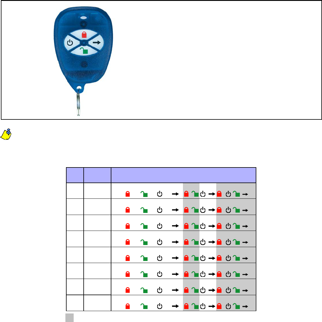
Remote Control Button Programming
RC# Section RC Buttons
Default: ( 1 5 0 0 0 0 0 0 )
1 [711] _____/_____/_____/_____/______/_____/_____/______
2 [712] _____/_____/_____/_____/______/_____/_____/______
3 [713] _____/_____/_____/_____/______/_____/_____/______
4 [714] _____/_____/_____/_____/______/_____/_____/______
5 [715] _____/_____/_____/_____/______/_____/_____/______
6 [716] _____/_____/_____/_____/______/_____/_____/______
7 [717] _____/_____/_____/_____/______/_____/_____/______
8 [718] _____/_____/_____/_____/______/_____/_____/______
Button Options Table
Empty Slot [FORCE] - Button disabled
1 - Regular arming
2 - Stay arming
3 - Instant arming
4 - Force arming
5 - Disarm
6 - Disarm when no alarm
7 - Regular arm and disarm
8 - Panic 1
9 - Panic 2
A - Panic 3
B - PGM Activation (Event Group #7, see PGM Programming)
C - PGM Activation (Event Group #8, see PGM Programming)
D - PGM Activation (Event Group #9, see PGM Programming)
MG-REM1
++ + +
++ + +
++++
++ + +
++ + +
++++
++ + +
++ + +
= These button combinations are not available with the MG-REM1or MG-RAC1 remote controls and cannot be programmed.

Spectra 1759MG - 26 - Programming Guide
Remote Control Assignment
Enter the appropriate section and press any button on the remote control twice to assign the remote control. If you hear a
rejection beep, an error has occurred or the remote control has already been assigned. To delete a remote control, enter the
desired section and then press the [FORCE] button.
Section #
[731] REMOTE CONTROL #1
[732] REMOTE CONTROL #2
[733] REMOTE CONTROL #3
[734] REMOTE CONTROL #4
[735] REMOTE CONTROL #5
[736] REMOTE CONTROL #6
[737] REMOTE CONTROL #7
[738] REMOTE CONTROL #8
Spectra 1759MG - 27 - Programming Guide
Zone Expansion Bus Modules
Only one SPC/APR3-ZX4 or one SPC/APR3-ZX8 can be connected to each Spectra control panel. The following sections
are for SPC-ZX4 version 1.0, APR3-ZX4 version 1.0, SPC-ZX8 version 1.0 and APR3-ZX8 version 2.0.
Modules with the APR- prefix are compatible with Spectra (versions 2.0 and higher) and DGP-848. Modules with the
APR3- prefix are compatible with Spectra (versions 2.0 and higher), DGP-848 and DGP-NE96.
Bold = Default Setting
PGM Programming (SPC-ZX8 and APR3-ZX8 Only)
The PGM will only activate or deactivate 100mS after the selected event occurs. The PGM Deactivation event can be used
as another activation event if the PGM Timer (section [655]) is programmed with a value other than 000. The system will
ignore the PGM if it has been programmed to follow the Global PGM (option [3] in section [650]). Only PGM events from the
table below can be used.
Section # Decimal Value (000-255) Description Default Value
[655] ___/___/___ seconds (000 = follow deactivation event) PGM1 TIMER 5 sec.
Section # Event Group # Sub-Group # Partition #
[656] PGM1 Activation Event ___/___ ___/___ ___/___
[657] PGM1 Deactivation Event ___/___ ___/___ ___/___
Section [650]: Options
Option
OFF ON
[1]
EOL (end-of-line) resistors for hardwire modules N No EOL N Use EOL Resistors
[2]
Zone Expansion Module tamper recognition N Disabled N Z1 becomes tamper input
[3]
PGM1 on SPC/APR3-ZX8 follows Global PGM
programmed in sections [124] & [125] N Disabled N Enabled
[4]
to
[8]
Future Use N N/A N N/A
Section [651]: Zone Assignment
Option See Zone Recognition Table on page 6. OFF ON
[1] Input Z1 =Expansion Input 1 N Disabled N Enabled
[2] Input Z2 =Expansion Input 2 N Disabled N Enabled
[3] Input Z3 =Expansion Input 3 N Disabled N Enabled
[4] Input Z4 =Expansion Input 4 N Disabled N Enabled
[5] Input Z5 (SPC/APR3-ZX8 only) =Expansion Input 5 N Disabled N Enabled
[6] Input Z6 (SPC/APR3-ZX8 only) =Expansion Input 6 N Disabled N Enabled
[7] Input Z7 (SPC/APR3-ZX8 only) =Expansion Input 7 N Disabled N Enabled
[8] Input Z8 (SPC/APR3-ZX8 only) =Expansion Input 8 N Disabled N Enabled
Event Group # Sub-Group # Partition #
For SPC-ZX8:
60 = Hardwire Zone Opened
61 = Hardwire Zone Closed
62 = Hardwire Tamper Opened
63 = Hardwire Tamper Closed
For APR3-ZX8:
60 = Hardwire Zone/Hardwire Tamper Opened
61 = Hardwire Zone/Hardwire Tamper Closed
01 = Expansion Input 1 - Section [651] - [1]
02 = Expansion Input 2 - Section [651] - [2]
03 = Expansion Input 3 - Section [651] - [3]
04 = Expansion Input 4 - Section [651] - [4]
05 = Expansion Input 5 - Section [651] - [5]
06 = Expansion Input 6 - Section [651] - [6]
07 = Expansion Input 7 - Section [651] - [7]
08 = Expansion Input 8 - Section [651] - [8]
99 = Any zone expansion bus module input
Not used; enter 00

Spectra 1759MG - 28 - Programming Guide
User Operation
Partitioning
The Spectra system is equipped with a partitioning feature which can divide the alarm system into two distinct areas identified
as Partition 1 and Partition 2. Partitioning can be used in installations where shared security systems are more practical, such
as an office/warehouse building. If the system is not partitioned, all User Codes and features will be recognized as
belonging to Partition 1.
Programming Access Codes
User Access Codes are personal identification numbers that allow users to enter certain programming modes, arm or disarm
the alarm system as well as activate or deactivate PGMs. Spectra security systems support the following:
System Master Code can arm or disarm any partition using any arming method and can create, modify or delete any User
Access Code. Only the System Master Code can modify or delete User Access Codes assigned to both partitions.
Master Code 1 is permanently assigned to partition 1 and can be used to create, modify or delete User Access Codes that
are assigned to partition 1.
Master Code 2 is permanently assigned to partition 2 (except when partitioning is disabled, Master Code 2 will be assigned
to partition 1) and can be used to create, modify or delete User Access Codes that are assigned to the same partition.
45 User Access Codes (including 1 Duress code)
How does a partitioned system work?
• Users can only arm or disarm their assigned partitions.
• Only zones assigned to Partition 1 will arm or disarm when Partition 1 is armed or disarmed.
• Only zones assigned to Partition 2 will arm or disarm when Partition 2 is armed or disarmed.
• Zones assigned to both partitions will arm when both partitions are armed and will disarm when
at least one disarms.
• Some of the system’s features can be programmed separately for each partition.
How Do I Program Access Codes?
1) Press [ENTER]
2) Key in the [SYSTEM MASTER CODE] or [MASTER CODE]
3) Key in 3-digit [SECTION] (see User Code Table)
4) Key in new 4- or 6-digit [ACCESS CODE]
[ENTER] flashes. Return to step 3
How Do I Delete Access Codes?
1) Repeat steps 1 to 3 (see above)
2) Press the [FORCE] key once for each digit in the access code (4 or 6 times) until the
keypad emits a Confirmation Beep.
User Code Table
Section User Codes
[001] User Code 001 = System Master Code
[002] User Code 002 = Master Code 1
[003] User Code 003 = Master Code 2
[004] TO [047] User Code 004 to User Code 047
[048] User Code 048 or Duress Code

Spectra 1759MG - 29 - Programming Guide
Programming Chime Zones
This feature allows users to program which zones will be Chime Enabled. A Chime Enabled zone will cause the keypad to
emit a rapid intermittent beep tone (BEEP-BEEP-BEEP-BEEP) advising the user every time it is opened. Each keypad must be
Chime Programmed separately. Keypad chimes must be re-programmed if the system suffers a total power loss (16-zone LED
and LCD Keypads only).
10-Zone LED Keypad
Press and hold any key from [1] to [10] for 3 seconds to activate or deactivate Chiming for zones 1 to 10. For example,
press and hold the [1] key to enable chiming on zone 1. If, after pressing and holding a key, the keypad emits a confirma-
tion beep, this means the chime feature has been enabled for that zone. If the keypad emits a Rejection Beep, this means
the Chime feature has been disabled for the corresponding zone.
16-Zone LED Keypad
Press and hold the [9] key. Enter the 2-digit (01 to 16) zone number(s). When the corresponding LED is on, the zone is
chimed. When the corresponding LED is off, the zone is unchimed. When the desired zones are chimed, press [ENTER].
LCD Keypad
Press and hold the [9] key. Enter the 2-digit (01 to 16) zone number(s) or use the arrow keys to scroll through the zones.
When the appropriate zone is displayed, press the [FNC1] key. When the desired zones are chimed, press [ENTER].
Keypad Muting
Press and hold the [CLEAR] key for 3 seconds to enable or disable keypad muting. When muted, the keypad will only beep
when a key is pressed or when the keypad emits a Rejection or Confirmation Beep. All other beep functions are disabled.
Keypad Backlight (1686H and 1686V Only)
The illumination level behind the keys can be modified to suit the user’s needs. There are four backlight levels. The [MEM] key
is used to set the desired level. Each consecutive push of the [MEM] key will increase the backlight level until the maximum
level is reached. After reaching the maximum level, the backlight level will return to the lowest level and the whole process is
repeated. To change the backlight level:
Quick Function Keys
Installer Test Mode
[ENTER] + [INSTALLER CODE] + [TBL] or [TRBL]
The Installer Test Mode allows you to perform walk tests where the bell/siren will squawk once to indicate an open zone and
twice to indicate a closed zone. To enter this mode, press [ENTER] + [INSTALLER CODE] + [TBL] or [TRBL]. The keypad will
emit a Confirmation Beep. To disable this mode, press the [TBL] or [TRBL] key again. The keypad will emit a Rejection Beep.
Test Report
[ENTER] + [INSTALLER/MASTER CODE] + [MEM]
Sends the Test Report report code programmed in section [211] to the central station.
Call WinLoad Software
[ENTER] + [INSTALLER/MASTER CODE] + [BYP]
This feature is used to establish communication between the control panel and a computer using the WinLoad Software.
After entering this mode, the control panel will dial the telephone number programmed in section [150].
Cancel Communication
[ENTER] + [INSTALLER/MASTER CODE] + [STAY]
Cancels all communication until the next reportable event. If the Master Code was used, only communication with WinLoad
would be cancelled.
Answer WinLoad Software
[ENTER] + [INSTALLER/MASTER CODE] + [FORCE]
Forces the control panel to pick-up an incoming telephone call.
How do I Modify the Backlight?
1) Press and hold the [MEM] key for 3 seconds
2) The [MEM] key will illuminate
3) Press the [MEM] key to set the desired backlight level
4) Press [CLEAR] or [ENTER] to exit

Spectra 1759MG - 30 - Programming Guide
Appendix A - Ademco CID Report Code List (Prog.)
If using the Ademco Contact ID Programmable code format, enter the 2-digit hexadecimal value from the table below (Prog.
Value) into sections [160] to [213] to program the desired report codes. To enter a 0 value press the [FORCE] key.
CID# Reporting Prog.
Code Value CID# Reporting Prog.
Code Value CID# Reporting Prog.
Code Value
MEDICAL ALARMS - 100 203 Gate Valve Sensor 2E 401 O/C by User 5B
100 Medical Alarm 01 204 Low Water Level 2F 402 Group O/C 5C
101 Pendant Transmitter 02 205 Pump Activated 30 403 Automatic O/C 5D
102 Fail to Report In 03 206 Pump Failure 31 404 Late to O/C 5E
FIRE ALARMS - 110 SYSTEM TROUBLES - 300 & 310 405 Deferred 5F
110 Fire Alarm 04 300 System Trouble 32 406 Cancel 60
111 Smoke 05 301 AC Loss 33 407 Remote Arm/Disarm 61
112 Combustion 06 302 Low System Battery 34 408 Quick Arm 62
113 Water Flow 07 303 RAM Checksum Bad 35 409 Keyswitch O/C 63
114 Heat 08 304 ROM Checksum Bad 36 REMOTE ACCESS - 410
115 Pull Station 09 305 System Reset 37 411 Callback Request Made 64
116 Duct 0A 306 Panel Program Changed 38 412 Success - Download Access 65
117 Flame 0B 307 Self-Test Failure 39 413 Unsuccessful Access 66
118 Near Alarm 0C 308 System Shutdown 3A 414 System Shutdown 67
PANIC ALARMS - 120 309 Battery Test Failure 3B 415 Dialer Shutdown 68
120 Panic Alarm 0D 310 Ground Fault 3C ACCESS CONTROL - 420
121 Duress 0E SOUNDER/RELAY TROUBLES - 320 421 Access Denied 69
122 Silent 0F 320 Sounder Relay 3D 422 Access Report By User 6A
123 Audible 10 321 Bell 1 3E SOUNDER RELAY DISABLES - 520
BURGLAR ALARMS - 130 322 Bell 2 3F 520 Sounder/Relay Disabled 6B
130 Burglary 11 323 Alarm Relay 40 521 Bell 1 Disable 6C
131 Perimeter 12 324 Trouble Relay 41 522 Bell 2 Disable 6D
132 Interior 13 325 Reversing 42 523 Alarm Relay Disable 6E
133 24-Hour 14
SYSTEM PERIPHERAL TROUBLES - 330 & 340
524 Trouble Relay Disable 6F
134 Entry/Exit 15 330 System Peripheral 43 525 Reversing Relay Disable 70
135 Day/Night 16 331 Polling Loop Open 44 COMMUNICATION DISABLES - 550 & 560
136 Outdoor 17 332 Polling Loop Short 45 551 Dialer Disabled 71
137 Tamper 18 333 Exp. Module Failure 46 552 Radio xmitter Disabled 72
138 Near Alarm 19 334 Repeater Failure 47 BYPASSES - 570
GENERAL ALARMS - 140 335 Local Printer Paper Out 48 570 Zone Bypass 73
140 General Alarm 1A 336 Local Printer Failure 49 571 Fire Bypass 74
141 Polling Loop Open 1B COMMUNICATION TROUBLES - 350 & 360 572 24-Hour Zone Bypass 75
142 Polling Loop Short 1C 350 Communication 4A 573 Burg. Bypass 76
143 Expansion Module Failure 1D 351 Telco Fault 1 4B 574 Group Bypass 77
144 Sensor Tamper 1E 352 Telco Fault 2 4C TEST/MISC. - 600
145 Expansion Module Tamper 1F 353 Long Range Radio 4D 601 Manual Trigger Test 78
24-HOUR NON-BURGLARY - 150 & 160 354 Fail to Communicate 4E 602 Periodic Test Report 79
150 24-Hour Non-Burglary 20 355 Loss of Radio Supervision 4F 603 Periodic RF Xmission 7A
151 Gas Detected 21 356 Loss of Central Polling 50 604 Fire Test 7B
152 Refrigeration 22 PROTECTION LOOP TROUBLES - 370 605 Status Report to Follow 7C
153 Loss of Heat 23 370 Protection Loop 51 606 Listen-in to Follow 7D
154 Water Leakage 24 371 Protection Loop Open 52 607 Walk Test Mode 7E
155 Foil Break 25 372 Protection Loop short 53 621 Event Log Reset 7F
156 Day Trouble 26 373 Fire Trouble 54 622 Event Log 50% Full 80
157 Low Bottled Gas Level 27 SENSOR TROUBLES - 380 623 Event Log 90% Full 81
158 High Temp 28 380 Sensor Trouble 55 624 Event Log Overflow 82
159 Low Temp 29 381 Loss of Super. -RF 56 625 Time/Date Reset 83
161 Loss of Air Flow 2A 382 Loss of Super. - RPM 57 626 Time/Date Inaccurate 84
FIRE SUPERVISORY - 200 & 210 383 Sensor Tamper 58 627 Program Mode Entry 85
200 Fire Supervisory 2B 384 RF xmtr. Low Battery 59 628 Program Mode Exit 86
201 Low Water Pressure 2C OPEN/CLOSE - 400 631 Exception Schedule Change 87
202 Low CO2 2D 400 Open/Close 5A 654 System Inactivity 88

Spectra 1759MG - 31 - Programming Guide
Appendix B - Ademco CID Report Code List (All Codes)
System Event Default Contact ID Report Code when
option [3] is on in section [136]
System Event Default Contact ID Report Code when
option [3] is on in section [136]
Arming with Master Code (##) 3 4A1 - Close by user Auxiliary supply trouble 1 3AA - System trouble
Arming with User Code (##) 3 4A1 - Close by user Bell output current limit 1 321 - Bell 1
Arming with Keyswitch (##) 3 4A9 - Keyswitch Close Bell absent 1 321 - Bell 1
Auto Arming 3 4A3 - Automatic Close Clock lost 1 626 - Time/Date inaccurate
Arm with PC software 3 4A7 - Remote arm/disarm Fire loop trouble 1 373 - Fire trouble
Late To Close 3 4A4 - Late to Close Wireless Transmitter
Low Battery
1 384 - RF xmtr. low battery
No Movement 3 4A4 - Late to Close Wireless Transmitter
Supervision Loss
1 381 - Loss of super. - RF
Partial arming 1 574 - Group bypass Module fault 1 333 - Expansion module failure
Quick arming 3 408 - Quick arm Printer fault 1 336 - Local printer failure
Fail to communicate with
central station
1 354 - Fail to communicate
Disarm with Master Code (##) 1 4A1 - Open by user Wireless Transmitter
Low Battery
1 384 - RF xmtr. low battery
Disarm with User Code (##) 1 4A1 - Open by user TLM trouble restore 3 351 - Telco 1 fault restore
Disarm with Keyswitch (##) 1 4A9 - Keyswitch Open AC Failure restore 3 3A1 - AC loss restore
Disarm after alarm with
Master Code (##)
1 4A1 - Open by user Battery Failure restore 3 3A9 - Battery test restore
Disarm after alarm with
User Code (##)
1 4A1 - Open by user Auxiliary supply trouble restore 3 3AA - System trouble restore
Disarm after alarm with
Keyswitch (##)
1 4A9 - Keyswitch Open Bell output current limit restore 3 321 - Bell 1 restore
Bell absent restore 3 321 - Bell 1 restore
Auto Arming Cancellation 1 4A5 - Deferred Open/Close Clock programmed 3 626 - Time/Date Reset
Disarm with PC software 1 4A7 - Remote arm/disarm Fire loop trouble restore 3 373 - Fire trouble restore
Disarm after an alarm with
PC software
1 4A7 - Remote arm/disarm Wireless Transmitter
Low Battery
3 384 - RF xmtr. low battery
Wireless Transmitter
Supervision Loss
3 381 - Loss of super. - RF
Zone Bypassed (##) 1 57A - Zone bypass Module fault restore 3 333 - Expansion module failure
restore
Zone alarm (##) 1 13A - Burglary Alarm Printer fault restore 3 336 - Local printer failure restore
Fire alarm (##) 1 11A - Fire alarm Fail to communicate with
central station
3 354 - Fail to communicate restore
Zone alarm restore (##) 3 13A - Burglary Alarm Restore
Fire alarm restore (##) 3 11A - Fire alarm Restore Cold Start 1 3A8 - System shutdown
Test Report engaged 1 6A2 - Periodic test report
Panic 1 - Emergency 1 12A - Panic alarm PC software communication
finished
1 412 - Successful - download access
Panic 2 - Medical 1 1AA - Medical alarm Installer on site 1 627 - Program mode Entry
Panic 3 - Fire 1 115 - Pull Station Installer programming finished 1 628 - Program mode Exit
Delinquency 1 654 - Inactivity
Recent closing 3 4AA - Open/Close
Global zone shutdown 1 574 - Group bypass
Duress alarm 1 121 - Duress
Zone shutdown (##) 1 57A - Zone bypass
Zone tampered (##) 1 144 - Sensor tamper
Zone tamper restore (##) 3 144 - Sensor tamper restore
AC Failure 1 3A1 - AC loss
Battery Failure 1 3A9 - Battery test failure
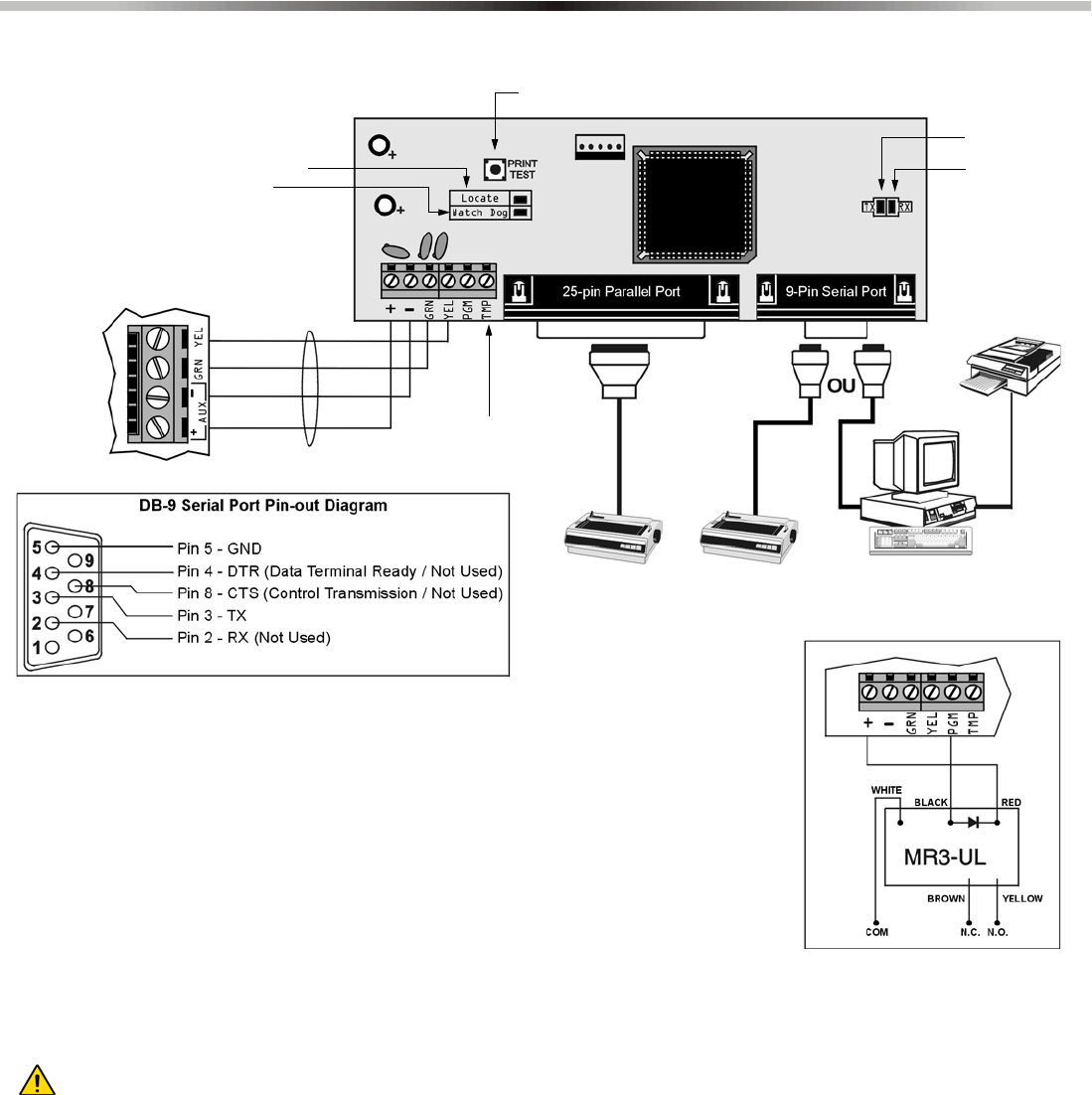
Spectra 1759MG - 32 - Programming Guide
Bus Module Connections
Printer Module (APR3-PRT1)
Remove AC power and battery before adding APR3-PRT1 to the system. Do not connect any modules more than
76m (250ft) from the control panel. Only one Printer Module can be connected per Spectra control panel.
A Green “Locate” LED: Remains illuminated during power up
B Red “Watchdog” LED: Flashes to indicate proper operation. If there is a communication
failure, the red LED will flash ON for one second and OFF for one second.
C Red “TX” LED: Flashes when the Printer Module is transmitting data through the serial
port only.
D 25-pin Parallel Port: Connect the Printer Module’s 25-pin parallel port to any dot matrix
printer. Note: The dot matrix printer must support a minimum of 80 columns.
E 9-Pin Serial Port: Connect the Printer Module’s 9-Pin serial port to a dot matrix printer.
Note: The dot matrix printer must support a minimum of 80 columns.
F 9-Pin Serial Port: Connect the Printer Module’s 9-Pin serial port to a computer’s COM
port to view the control panel’s events on the computer’s monitor. The events displayed
on the monitor can then be printed through the printer connected to the computer.
Spectra 1759MG
Control Panel
Communication
Bus
RX LED
reserved for
future use
Press the “PRINT TEST” switch to perform a print test
Not Used
A
B
DE
F
C
Connecting the PGM Output
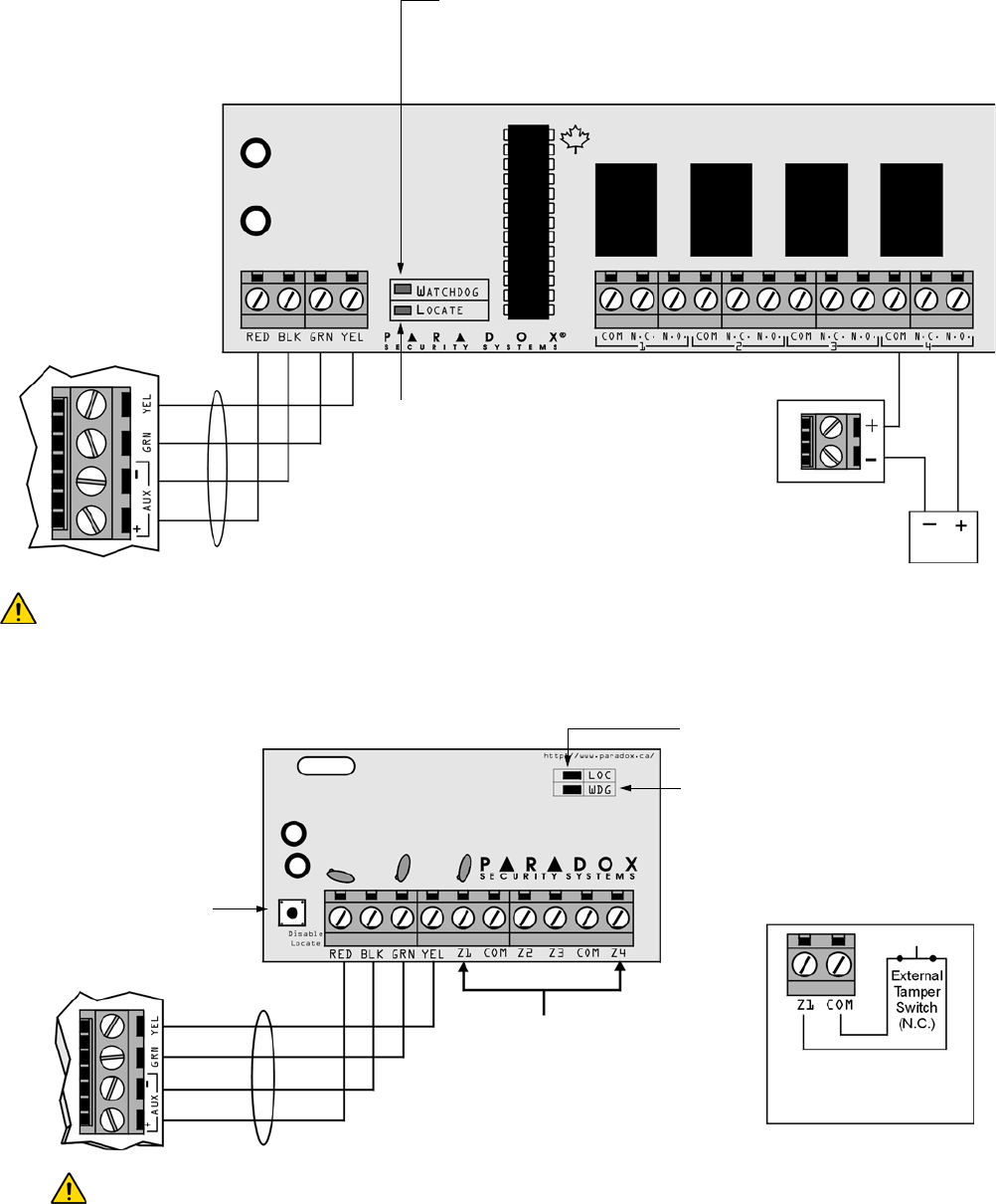
Spectra 1759MG - 33 - Programming Guide
4-PGM Output Module (APR3-PGM4)
4-zone expansion Bus Module (SPC-ZX4 and APR3-ZX4)
Red “Watchdog” LED:
Status: flashes once per second to indicate proper operation.
Flash 1 second on and 1 second off: The module is experiencing a communication
failure with the control panel.
External Power Supply
(Recommended: Paradox
PSW817 1.75A Switching
Power Supply)
To Spectra 1759MG
control panel
Not Used
Any device such as a garage
door opener, light or siren
Communication
Bus
Remove AC and battery from the control panel before adding the 4-PGM Output Module to the system. Do
not connect the APR3-PGM4 more than 76m (250ft) from the control panel. Only one APR3-PGM4 can be
connected per Spectra control panel.
Not Used
Red “WDG” LED:
Status = Flashes to indicate proper operation.
Flash 1 sec. on & 1 sec. off = Trouble and/or
communication failure.
Connect the detection devices to the
module's input terminals exactly as shown
in the Spectra 1759MG Reference &
Installation Manual.
Not Used
Spectra 1759MG
control panel Communication
Bus
Remove AC and battery power from the control panel before connecting the module to the
communication bus. Do not connect the APR3-ZX4 or SPC-ZX4 more than 76m (250ft) from the
control panel. Only one APR3-ZX4 or one SPC-ZX4 can be connected per Spectra control panel.
Input terminal Z1 can be used
as an anti-tamper switch input
Option [2]: Section [650]
Connecting the Anti-
Tamper Switch
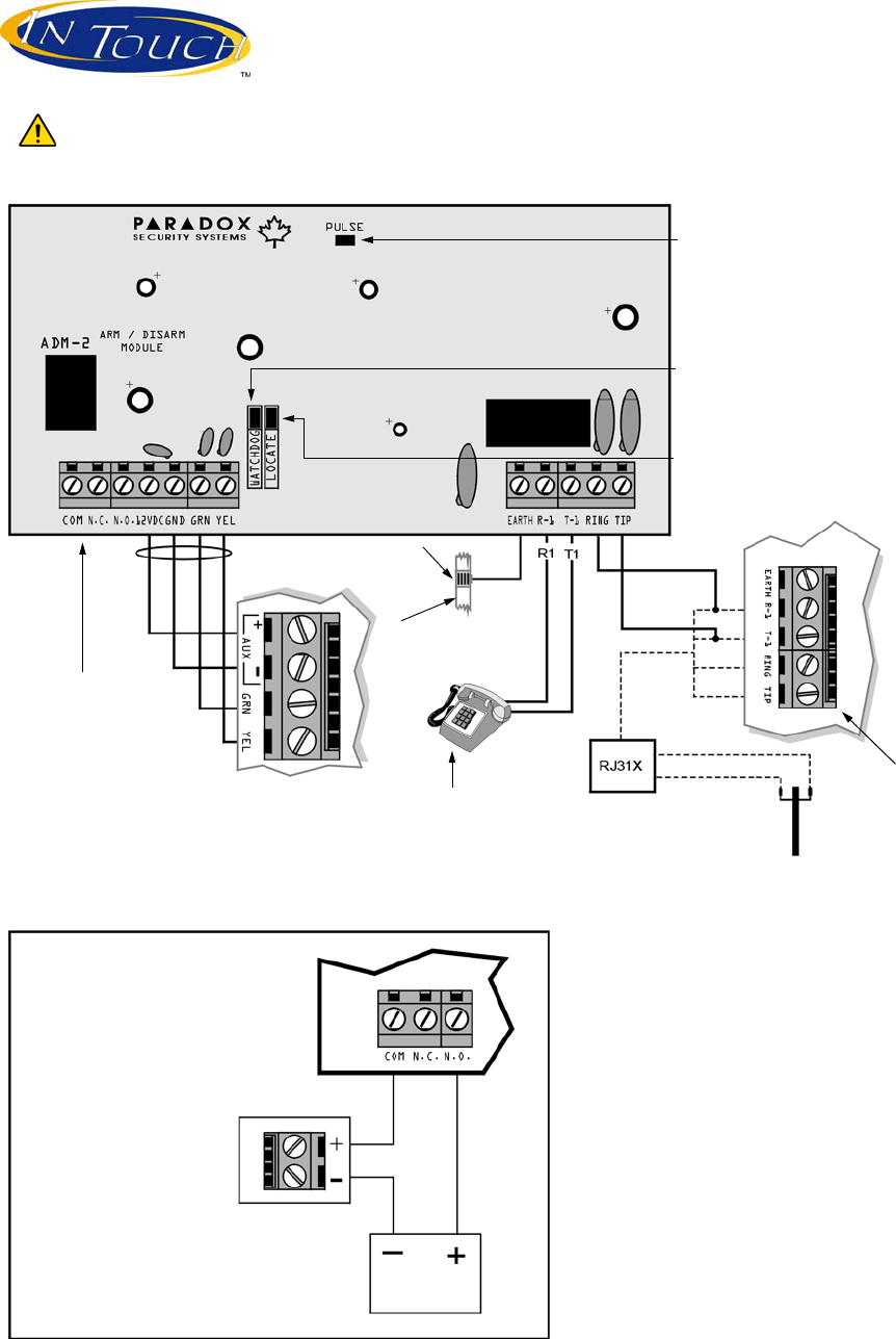
Spectra 1759MG - 34 - Programming Guide
Voice-assisted Arm/Disarm Bus Module (APR3-ADM2)
Green "PULSE"LED:
Monitors the dialer. The LED will illuminate when the dialer
is in use. When the dialer is not being used, the LED will
remain off.
Red “WATCHDOG” LED:
Flashes once every second = normal.
Flashes 1 second on & 1 second off = trouble and/or
communication failure.
Communication
Bus
Ground
clamp
Cold water pipe
grounding
Household
telephone
Refer to Inset 1
To Spectra 1759MG
control panel
Spectra 1759MG
Dialer
Not Used
Inset 1: Connecting the APR3-ADM2 PGM Output
Partial view of the
APR3-ADM2
External Power Supply
(Recommended: Paradox
PSW817 1.75A Switching
Power Supply)
Any device such as a garage
door opener, light or siren
Remove AC and battery power from the control panel before adding the APR3-ADM2 module to the
system. Do not connect the APR3-ADM2 more than 76m (250ft) from the control panel. Only one APR3-
ADM2 can be connected per Spectra control panel.
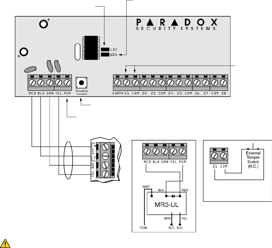
Spectra 1759MG - 35 - Programming Guide
8-Zone Expansion Bus Modules (SPC-ZX8 and APR3-ZX8)
Red “WDG” LED:
Flash once every sec. = normal.
Flash 1 sec. on & 1 sec. off = Trouble and/or communication failure.
Not Used
Inset 2
Not Used
Inset 1
Refer to the Spectra 1759MG Reference & Installation Manual
about connecting devices to the Expansion Input Terminals.
Communication
Bus Spectra 1759MG
control panel
Inset 1: Connecting the
PGM output Inset 2: Anti-Tamper
Switch Connection
Input terminal Z1 can be used
as an anti-tamper switch input.
Option [2]: Section [650]
Remove AC power and battery before adding a module to the system. Do not connect the APR3-ZX8
or SPC-ZX8 more than 76m (250ft) from the control panel. Only one SPC-ZX8 or APR3-ZX8 can be
connected per Spectra control panel.
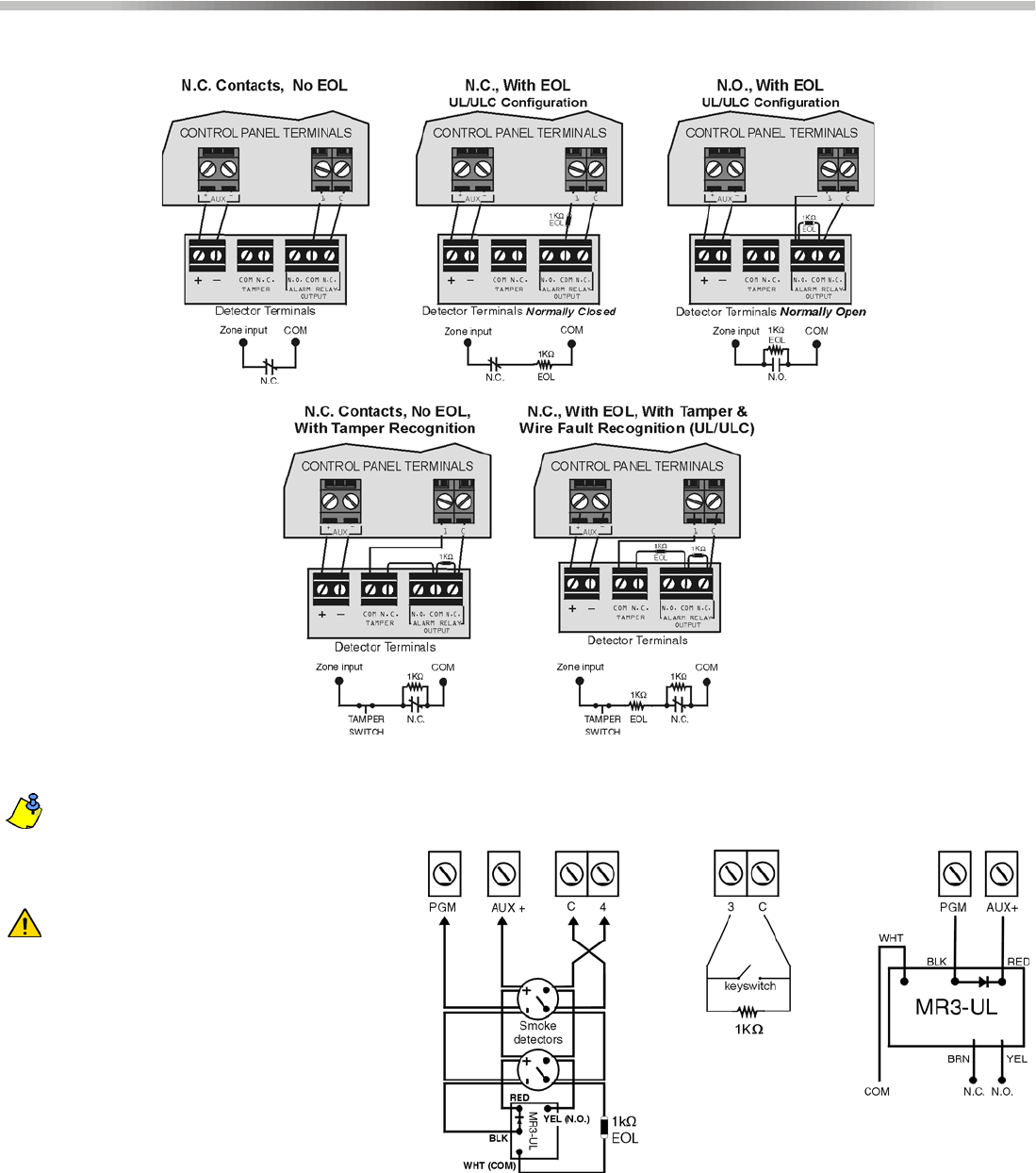
Spectra 1759MG - 36 - Programming Guide
Hardware Connections
Single Zone Inputs
Connecting Fire Circuits, Keyswitches and PGMs
Program the PGM with the “[PG]/[FNC1] Key
was pressed” Activation Event so that the
smoke detectors can be reset by pressing the
[PG] or [FNC1] key. See Event Group # 5 on
page 9.
All 4-wire smoke detectors must be
connected using the daisy chain
configuration.
Programming a Wireless Fire Zone
Fire zones cannot be assigned to expansion zones. As
a result, when installing a wireless smoke detector, the
corresponding zone must be programmed as follows:
1) Enter [5] in the Zone Definition to define it as a
24Hr Burglary Alarm (see page 7).
2) Disable [4] and enable [5] in Zone Options to set
the zone’s alarm type to a pulsed Audible Alarm
(see page 7).
3) Disable [1] and [2] in Zone Options to disable the
zone’s Auto Zone Shutdown and Bypass Enabled
features (see page 7).
Fire Circuits
4-Wire Installation
Control Panel Terminals
Keyswitch PGM
4) Change the zone’s report code from a Burglary Report Code (Prog. Value
11) to a Fire Report Code (Prog. Value 04). See Appendix A on page 30. If
using Ademco Contact I.D., set the Contact ID Options from All Codes to
Programmable (section [136] option [3] = OFF) and then enter the report
code manually (see page 14).
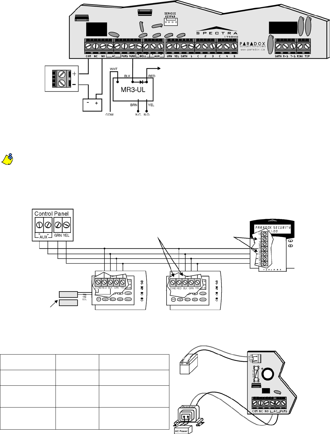
Spectra 1759MG - 37 - Programming Guide
Alarm Relay and PGM Connections
Connecting More Than Two Keypads
If there are more than 2 keypads connected to the control panel and at least one keypad zone is being used, connect as
shown and program as described in the Spectra 1759MG Reference & Installation Manual.
When a 1641 LCD keypad is connected to Spectra, the Keypad Zone Sending option (Option [2] key [1]) determines
whether the status of the keypad zone will be transmitted to the control panel. Refer to the 1641 Installer’s Guide for more
information. The Keypad Zone Sending option of the 1641 keypad must be enabled during the following conditions:
• If you are using both keypad zones and at least one is from a 1641 keypad.
• If you are using the keypad zones of other types of keypads, such as a 1686H 10-zone LED keypad, and the keypad
zone definition of the 1641 keypad (keypad zone 1 or keypad zone 2; Option [2] key [3]) matches that of another
connected keypad.
AC Power & Backup Battery Connections
Transformer Requirements Table
Transformer: Amseco XP-1620
16VAC 20VA * Recommended: 16VAC 40VA
UL: Basler BE156240CAA007
Spectra DC Power
Supply rated at:
1.2A 1.5A
Auxiliary Supply can
provide a maximum of:
typ: 600mA
max: 700mA
typ: 600mA
max: 700mA
UL installations: typ. 200mA
Acceptable Battery
Charge Currents
(section [127] option [5])
350mA 350mA / 700mA
* Not verified by UL
PGMs
When the device connected to a PGM is powered by:
AUX+ terminal = must not exceed 700mA
External power supply = PGM1 cannot exceed 150mA
PGM2 cannot exceed 1A
If power supply's current limit is less than
that of the PGM it is connected to, then the
current consumption cannot exceed the
power supply's current limit.
PGM2 can be used as a strobe output.
AUX+
External
power
supply
Alarm Relay (5A) can be
programmed to follow the
BELL output or the Global
PGM
External
Power
Supply
Any device such
as a strobe light
or siren
Do not place a jumper across the zone
and “BLK” input terminals of the keypads
that are not using their keypad zones.
A Door Contact or any
other detection device. 1686H
(Using keypad zone) 1686H
(Not using keypad zone)
1641 LCD Keypad
(Not using keypad zone)
Be sure to enable option [1] (”Keypad
Zone Sending”) of option [2]
(”Options”) in the 1641’s LCD
Programming Mode.
Partial view of Spectra
1759MG control panel
UL Warning:
A 12Vdc / 7Ah battery
is required to comply
with UL fire
requirements.
Caution:
Disconnect battery
before replacing the
fuse.
Rechargeable Battery
UL/ULC - 12Vdc / 4Ah or 7Ah
Warning:
Improper connection
of the transformer may
result in damage to the system.
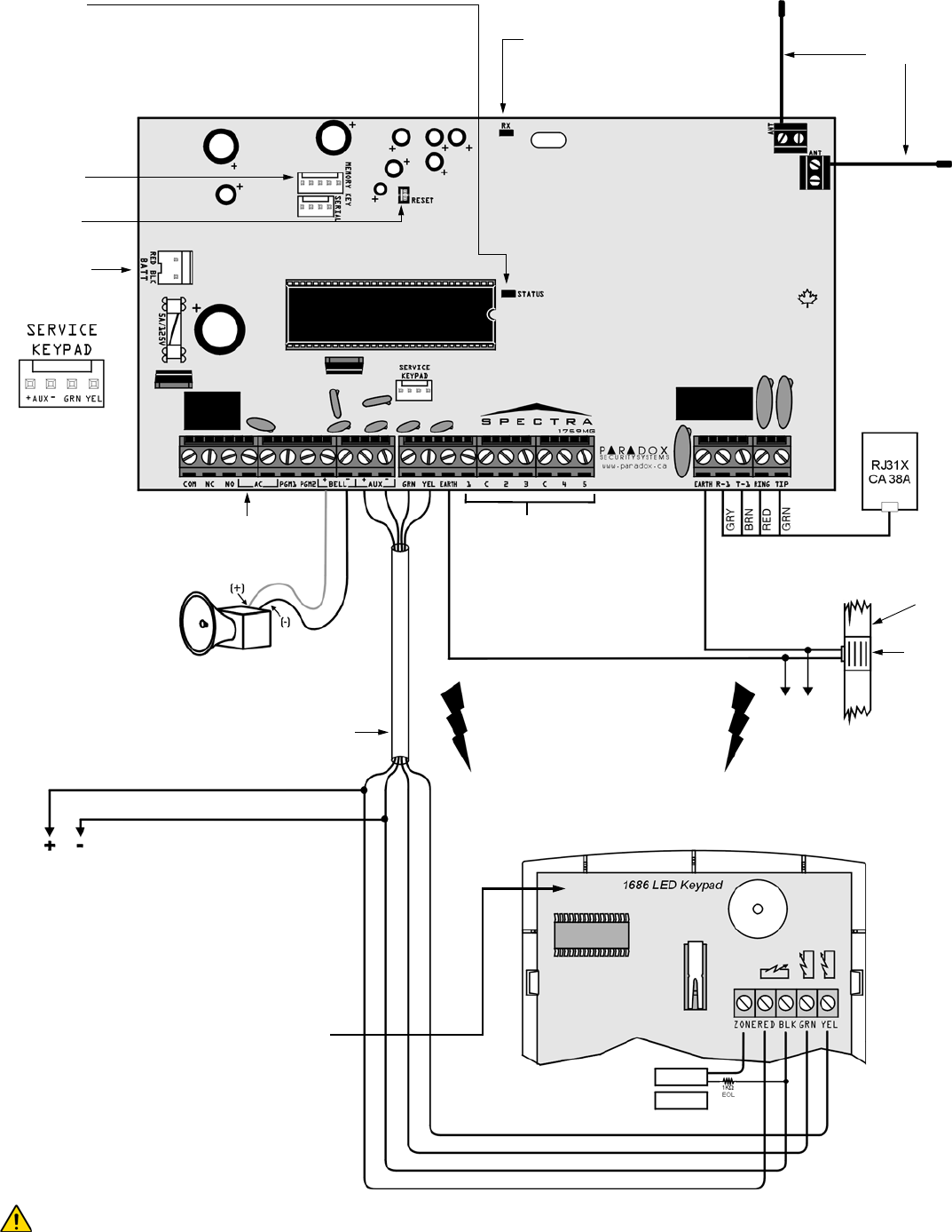
Spectra 1759MG - 38 - Programming Guide
Spectra 1759MG PCB Layout
For UL and C-UL warnings, refer to the UL and C-UL Warnings section at the back of the Spectra 1759MG
Reference & Installation Manual.
To connect the 5A Alarm Relay and the PGMs,
refer to Alarm Relay and PGM Connections on
page 37. To connect AC power, refer to AC Power
& Backup Battery Connections on page 37.
Refer to Single Zone Inputs on
page 36
Refer to AC Power
& Backup Battery
Connections on
page 37.
For the keypad’s zone, EOL and tamper configurations,
refer to page 5.
Warning:
Do not connect
keypads more than
76m (250ft) from the
control panel.
A Door Contact or any other detection
device can be connected to the
Keypad Zone.
AUX Power
Refer to transformer requirements on page 37 for Aux.
Power Output. To connect additional wiring to auxiliary
power, use the red (+) and black (-) keypad connectors.
Auxiliary power will shut down if current exceeds 1.1A. If the
auxiliary output is overloaded and is shut down, you must
disconnect all loads from the output for at least 10 seconds
before reconnecting any load back to the auxiliary output.
Spectra Keypads
The maximum number of keypads per installation is dependent on the auxiliary
output, which cannot exceed 700mA.
To provide maximum lightning protection
we strongly recommend having separate
earth connections for the dialer and zone
ground terminals.
To metallic
enclosure
Ground
clamp
AWG#14 single
conductor solid
copper wire
Cold water
pipe
grounding
The "BELL" output will
shutdown if the current
exceeds 3A.
Communication Bus
Warning:
Disconnect
telephone line
before servicing.
Four pin connector
can be used for
quick installation of a
Spectra keypad or
Expansion Module.
Warning:
Do not cut, bend or
alter the antennae
and ensure that
electrical wires do
not cross over the
antennae, as this
may affect signal
reception.
Paradox Memory
Key (PMC-3)
Reset Jumper
Antennae
"RX" LED:
Flashes quickly when
receiving signals from
wireless devices.
"STATUS" LED:
Flash once every second = normal
Flashes ON 1 second and OFF 1 second = trouble
Always ON = panel is using phone line
Fast flash 4 seconds after power up = installer lock enabled
Warning:
This equipment must be installed and maintained by
qualified service personnel only.
Warranty
Paradox Security Systems Ltd. (“Seller”) warrants its products to be free from defects in materials and workmanship under
normal use for a period of one year. Except as specifically stated herein, all express or implied warranties whatsoever,
statutory or otherwise, including without limitation, any implied warranty of merchantability and fitness for a particular
purpose, are expressly excluded. Because Seller does not install or connect the products and because the products may be
used in conjunction with products not manufactured by Seller, Seller cannot guarantee the performance of the security
system and shall not be responsible for circumstances resulting from the product’s inability to operate. Seller obligation and
liability under this warranty is expressly limited to repairing or replacing, at Seller's option, any product not meeting the
specifications. Returns must include proof of purchase and be within the warranty period. In no event shall the Seller be liable
to the buyer or any other person for any loss or damages whether direct or indirect or consequential or incidental, including
without limitation, any damages for lost profits stolen goods, or claims by any other party, caused by defective goods or
otherwise arising from the improper, incorrect or otherwise faulty installation or use of the merchandise sold.
Notwithstanding the preceding paragraph, the Seller’s maximum liability will be strictly limited to the purchase price of the
defective product. Your use of this product signifies your acceptance of this warranty.
BEWARE: Dealers, installers and/or others selling the product are not authorized to modify this warranty or make additional
warranties that are binding on the Seller.
© 2002-2005 Paradox Security Systems Ltd. All rights reserved. Specifications may change without prior notice. One or more
of the following US patents may apply: 6215399, 6111256, 5751803, 5721542, 5287111, 5119069, 5077549, 5920259 and
5886632. Canadian and international patents may also apply.
Spectra, Digiplex and Magellan are trademarks or registered trademarks of Paradox Security Systems Ltd. or its affiliates in
Canada, the United States and/or other countries.

For technical support in Canada or the U.S., call 1-800-791-1919 for English or 1-866-912-0600 for French, Monday to Fri-
day from 8:00 a.m. to 8:00 p.m. EST. For technical support outside Canada and the U.S., call 00-1-450-491-7444, Monday
to Friday from 8:00 a.m. to 8:00 p.m. EST. Please feel free to visit our website at www.paradox.ca.
780 Industriel Blvd., Saint-Eustache (Quebec) J7R 5V3 CANADA
Tel.: (450) 491-7444 Fax: (450) 491-2313
www.paradox.ca
PRINTED IN CANADA - 01/2005 1759MG-EP05