Paradox Security Systems DCT6 Wireless Magnetic Door Contact User Manual DCT6 Installation Manual
Paradox Security Systems Wireless Magnetic Door Contact DCT6 Installation Manual
Users Manual

1
Open/Close Breaking the Flange
DCT6
Wireless Door
Cont
act
V1.
0
Open
Close
1.6. in. / 4 cm
(flange)
0.8 in. / 2.1
cm
Installation Manual
Introduction
The DCT6 is a wireless magnetic door contact that is
discreetly hidden within the frame of a door or window.
Installation
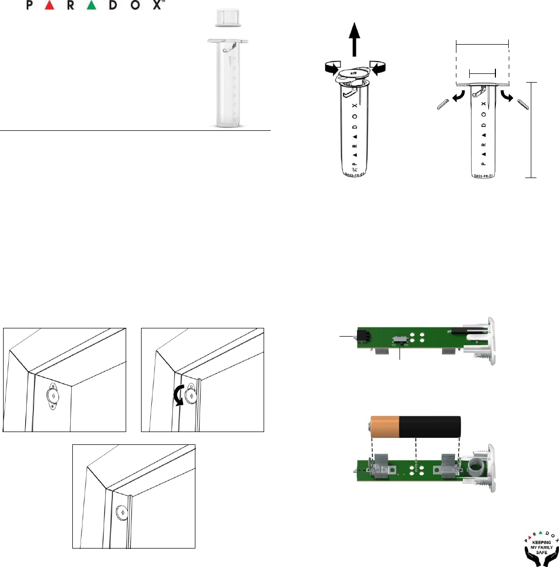
Transmitter: Drill a 3/4 in. x 2.75 in. depth (16 mm x 70 mm depth)
hole in the frame and insert the DCT6 transmitter. Secure the
FIGURE 2 FIGURE 3
Setting RF Frequency / Replacing Battery
2.8 in. /
7.3 cm
transmitter body A- with two screws or B- with one screw and
remove one flange if it interferes with the radial opening or C-
press fit installation on narrow frames, see Figure 3, A, B and C.
Magnet: Drill a 3/4 in. x 1.1 in. (19 mm x 28 mm) hole in the frame
to be aligned with the transmitter when door/window is closed
and insert the magnet with press fit. Make sure it is aligned with
the transmitter and that the gap, when closed, is not greater than
0.4 in. / 10 mm.
1. Open the top of the DCT6 transmitter, turning the cover
counter clockwise, see Figure 2.
2. Locate the switch on the PCB, as shown in Figure 4.
3. Slide the switch to the desired frequency 433 MHz or
868 MHz.
4. Remove the battery for a few seconds. Replace the battery
back (verify the polarity and insert properly + and - marked on
the battery terminals, see Figure 5.
Anti-Tamper
Switch
Flange
removed to
allow opening
A - Two Screws B - One Screw / One Flange
C - Press
Fit
Selectable
RF
433 MHz / 868
MHz
FIGURE
4
FIGURE
5
We recommend to replace the battery ever 3 years to
avoid leakage.

2
EVO Programming and Testing
1. Enter section [4003]
2. Enter RTX3 or K641LX serial number.
3. Enter section [101] to [132] to assign the DCT6.
4. Open the transmitter as per Figure 2 then close it. This will register the DCT6 entered section.
5. Test signal strength by entering section [601] to [632].
6. Open the transmitter as per Figure 2 then close it.
7. Verify the signal strength on your LCD keypad or TM70/TM50.
MGSP Programming and Testing
1. Enter available section to assign the DCT6 [061] - [092].
2. Open the transmitter as per Figure 2, then close it. This will register the DCT6 to the entered section.
3. Test signal strength by entering correspondent section [101]
to [132].
4. Open the transmitter as per Figure 2 then close it.
5. Verify the signal strength on your LCD keypad, TM70/TM50.
Technical Specifications
Power
1 x AAA alkaline battery
RF Frequency
Selectable 433/868 MHz on-board
Battery Life
3 years (replace to avoid
leakage) Based on 10
openings/closing a day
Wireless Range
MG5000/MG5050/RTX3 - 40m
(130 ft) MG6250 - 20m (65 ft)
Wireless range is based on typical
indoor installation
Operating
Temperature
-20°C to 50°C (-4°F to 122°F)
Anti-tamper Switch
Cover opening
Magnet distance
Up to 0.4 in. / 10 mm
Dimensions
7.3 x 2.1 x 2.1 cm (2.8 x 0.8 x 0.8 in.)
Anti-Tamper
Switch
Cover opening
Approvals
CE, EN 50131 Grade 2
Remarks
In-frame installation
Supervision
Live supervision, Battery low
Compatibility
Magellan Panels, MG6250,
K32LX, K641LX, RTX3, RX1
3
FCC and Industry Canada Compliance Statement
This device complies with FCC Rules Part 15 and with Industry
Canada license exempt RSS standard(s). Operation is subject to
two conditions:
1. This device may not cause harmful interference.
2. This device must accept any interference that may be
received or that may cause undesired operation.
Le present appareil est conforme aux CNR d'Industrie Canada
applicables aux appareils radio exempts de licence. L'exploitation
est autorisee aux deux conditions suivantes:
1. l'appareil ne doit pas produire de brouillage, et
2. l'utilisateur de l'appareil doit accepter tout brouillage
radioelectrique subi, meme si le brouillage est susceptible d'en
compromettre le fonctionnement.
FCC WARNING
This equipment has been tested and found to comply with
the limits for a Class B digital device, pursuant to Part 15
of the FCC Rules. These limits are designed to provide
reasonable protection against harmful interference in a
residential installation.
This equipment generates, uses and can radiate radio frequency
energy and, if not installed and used in accordance with the
instructions, may cause harmful interference to radio
communications.
However, there is no guarantee that interference will not occur in
a particular installation. If this equipment does cause harmful
interference to radio or television reception, which can be
determined by turning the equipment off and on, the user is
encouraged to try to correct the interference by one or more of the
following measures:
• Reorient or relocate the receiving antenna.
• Increase the separation between the equipment and the receiver.
• Connect the equipment into an outlet different from that to which
the receiver is connected.
• Consult the dealer or an experienced radio/TV technician for help.
Changes or modifications to this equipment not expressly
approved by the party responsible for compliance (Paradox
Security Systems Ltd.) could void the user’s authority to operate
the equipment.
Warranty
For complete warranty information on this product, please refer to
the
Limited Warranty Statement is found on the website:
www.paradox.com/terms or contact your local distributor.
Specifications may change without prior notice.
Patents
US, Canadian and international patents may apply. Paradox is a
trademark or registered trademark of Paradox Security Systems
(Bahamas) Ltd.
This Class B digital apparatus complies with Canadian ICES-003.
-Cet appareil numerique de la classe B est conforme a la norme NMB-003 du Canada.