Paradox Security Systems MG6060 MG-6060 User Manual Adobe PDF Job 2
Paradox Security Systems MG-6060 Adobe PDF Job 2
UserManual.wiki
>
Paradox Security Systems
>
MG6060 User Manual
>
Installation guide with FCC warnings
Contents
1.
Installation guide with FCC warnings
2.
User guide
Installation guide with FCC warnings
Navigation menu
Upload a User Manual
Namespaces
Wiki Guide
HTML
PDF
Info
Views
User Manual
Discussion / Help
Navigation
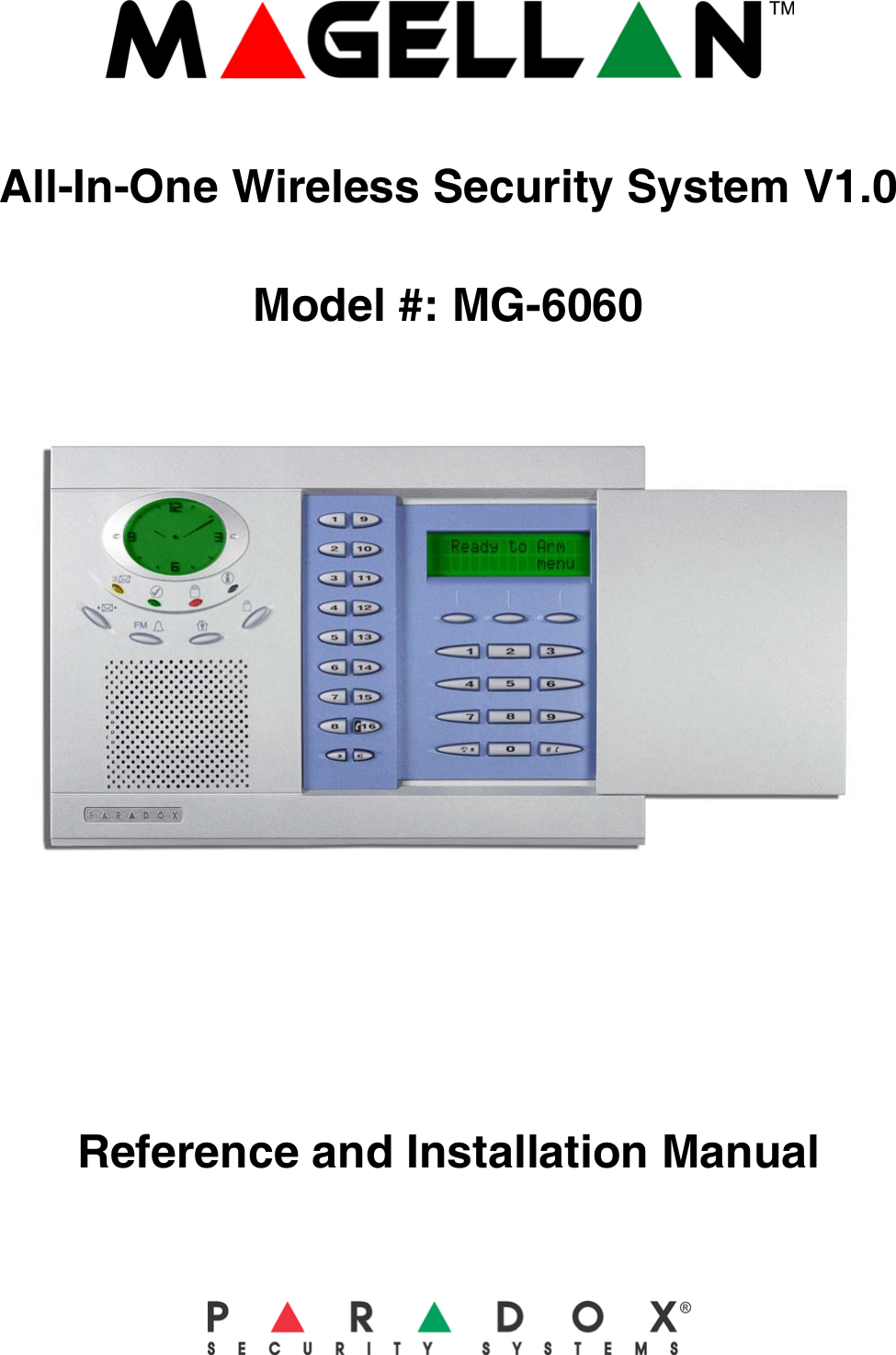
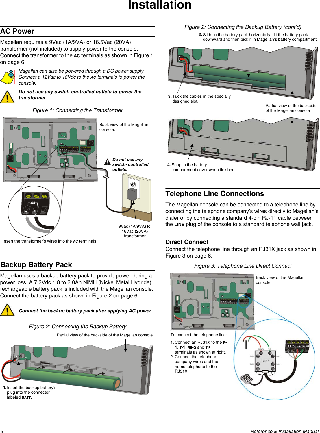
![Paradox Magellan Systems 3IntroductionAbout Magellan and this ManualMagellan is designed for fast and easy installation. Simply remove it from the box, mount the console and wireless transmitters, apply power and Magellan is ready to protect your home. Magellan has already been pre-programmed with the required settings for a basic security installation.Some of Magellan’s features can be programmed through a quick Installer Menu (menu programming) or through section programming. Use the quick setup chapter (page 4) to install the Magellan console quickly and with the basic programming required for a standard security application. All other chapters (pages 6 to 33) are for advanced section programming. These other chapters provide more in-depth and precise information if more advanced programming is required.We recommend that you read this entire manual before you begin installation.ConventionsSpecificationsPower input: AC*: 9Vac, 1A/9VA transformer or 16.5Vac, 20VA transformerorDC: 12Vdc to 18Vdc power supplyCurrent consumption:With AC input: 600mAorWith DC input: 400mABackup Battery: 7.2Vdc, 1.8 to 2.0Ah NiMH rechargeable battery pack (order # 0780100178)PGMs: Two N.O. solid-state relays (not polarized)Internal resistance - 169 (max.)Max. current consumption - 50mA* It is recommended that you use a 9Vac 1A/9VA transformer to power the Magellan console. The console will generate less heat when connected to a 9Vac transformer than when connected to a 16.5Vac transformer.This symbol designates a reference to another section, manual or guide.This symbol designates either a warning or important information.This symbol designates a reminder or suggestion.[DATA] =- Text shown in this manner designates data or programming information that is entered through the console’s keypad.- Text shown in this manner can also designate a specific key that has to be pressed.](https://usermanual.wiki/Paradox-Security-Systems/MG6060.Installation-guide-with-FCC-warnings/User-Guide-481305-Page-5.png)
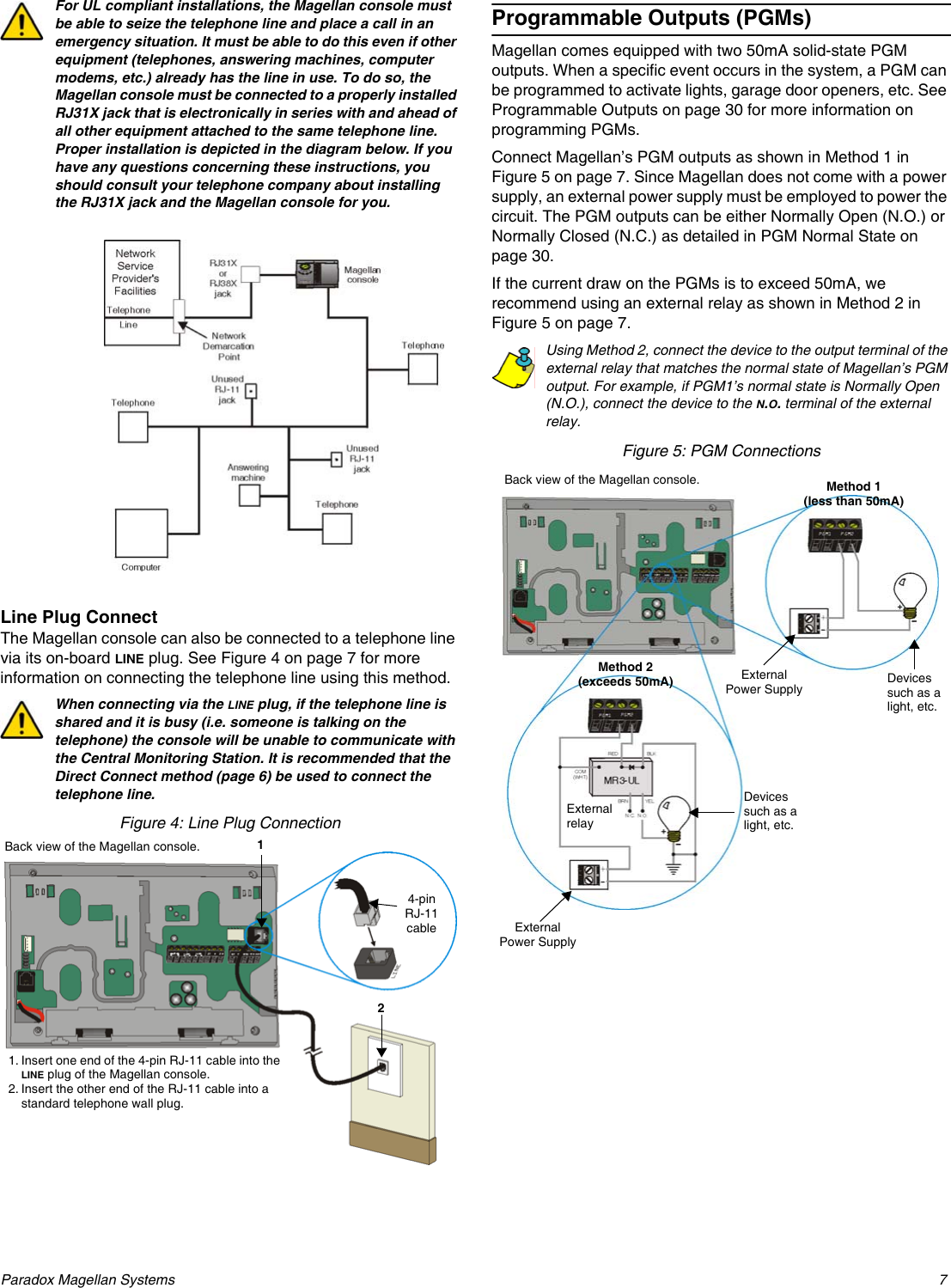
![4 Reference & Installation ManualQuick SetupFollow these steps to quickly set up Magellan with the required settings for a basic security installation.1.Getting Started1. After powering up for the first time, press [START] to access the Installer Menu.2. The first menu option will appear. Press [NEXT] to go to the “User Profile” menu.2.User Programming1. From the “User Profile” menu, press [OK].2. Select which user you wish to add by pressing [NEXT]. When the desired user appears, press [OK] and follow the menus to set:- Access Code- User Label- Remote ControlWhen you are done the next menu option will appear (see Central Station Reporting below).For more in-depth programming of the remote controls, see Programming the Remote Control’s Buttons on page 18.3.Central Station Reporting1. From the “Communicator” menu, press [OK].2. Press [OK] and follow the menus to set:- Telephone numbers- Account Number - Report FormatWhen you are done the next menu option will appear. Press [NEXT] until you see the “Zone Profile” menu or press the [6] key to immediately access the “Zone Profile” menu.For more in-depth programming of the console’s communication features, see Reporting and Dialer Settings on page 24.4.Adding and Programming Zones1. From the “Zone Profile” menu, press [OK].2. Select which zone you wish to add by pressing [NEXT] and press [OK] when the desired zone number appears.3. Press the tamper switch on the transmitter you wish to assign to the selected zone. Follow the menus to set:- Zone Label- Zone Type- Other ZonesWhen you are done the next menu option will appear. Press [NEXT] until you see the “System Test” menu or press the [5] key to immediately access the “System Test” menu.For more in-depth programming of the console’s zones, see Zone Programming on page 13 and Wireless Programming on page 17.5.Testing the Magellan System1. From the “System Test” menu, press [OK].2. Select which test you wish to perform by pressing [NEXT] and press [OK] when the desired test appears. The following tests can be performed:- Zone tests- Remote control tests- Reporting tests- Hardware testsWARNING! When testing the hardware, the speaker and sirens will also be tested. Avoid close proximity to the Magellan console when performing the hardware test to avoid any damage to your hearing.](https://usermanual.wiki/Paradox-Security-Systems/MG6060.Installation-guide-with-FCC-warnings/User-Guide-481305-Page-6.png)
![Paradox Magellan Systems 5When you are done the next menu option will appear. Press [NEXT] until you see the “Passwords” menu or press the [8] key to immediately access the “Passwords” menu.6.Passwords1. From the “Passwords” menu, press [OK].2. Select which password(s) or code(s) you wish to program by pressing [NEXT] and press [OK] when the desired password appears. The following passwords can be programmed:- Installer code- Maintenance code- Panel ID- PC PasswordWhen you are done the next menu option will appear. Press [EXIT].For more in-depth programming of the console’s passwords, see User Codes on page 12 and WinLoad Software Settings on page 33.7.Time and Date1. Press the [MENU] key.2. Press [NEXT] until you reach the “Time and Date” menu and press [OK] or press the [3] key to access the “Time and Date” menu.3. Select the time format (12Hr-clock or 24Hr-clock) and then program the time. Press [OK] when done.Program the date by entering the 4-digit year first, followed by the 2-digit month and then the 2-digit day. Press [OK] when done.Deleting Zones1. From the “Zone Profile” menu, press [OK].2. Select which zone you wish to delete by pressing [NEXT] and press [OK] when the desired zone number appears.3. Press [YES].4. Press [YES]. To delete another zone, press [YES] and then repeat steps 2 to 4.When you are done the next menu option will appear. Press [NEXT] until you see the “System Test” menu or press the [5] key to immediately access the “System Test” menu.For more in-depth programming of the console’s zones, see Zone Programming on page 13 and Wireless Programming on page 17.](https://usermanual.wiki/Paradox-Security-Systems/MG6060.Installation-guide-with-FCC-warnings/User-Guide-481305-Page-7.png)
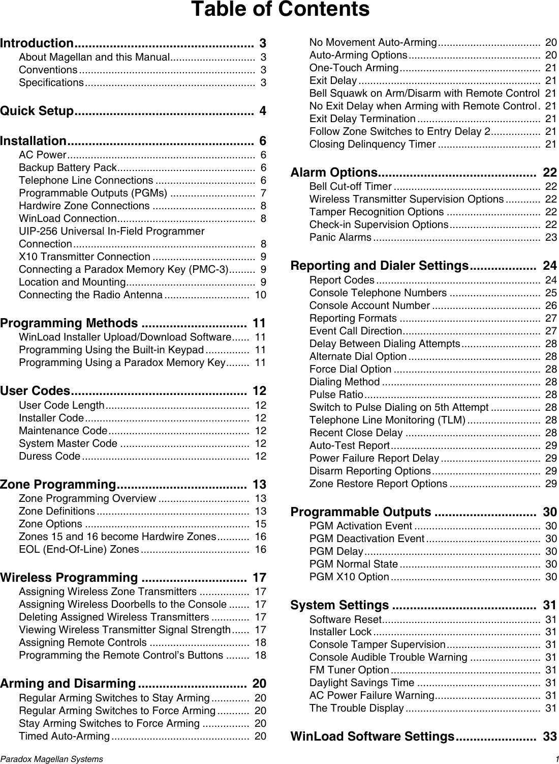
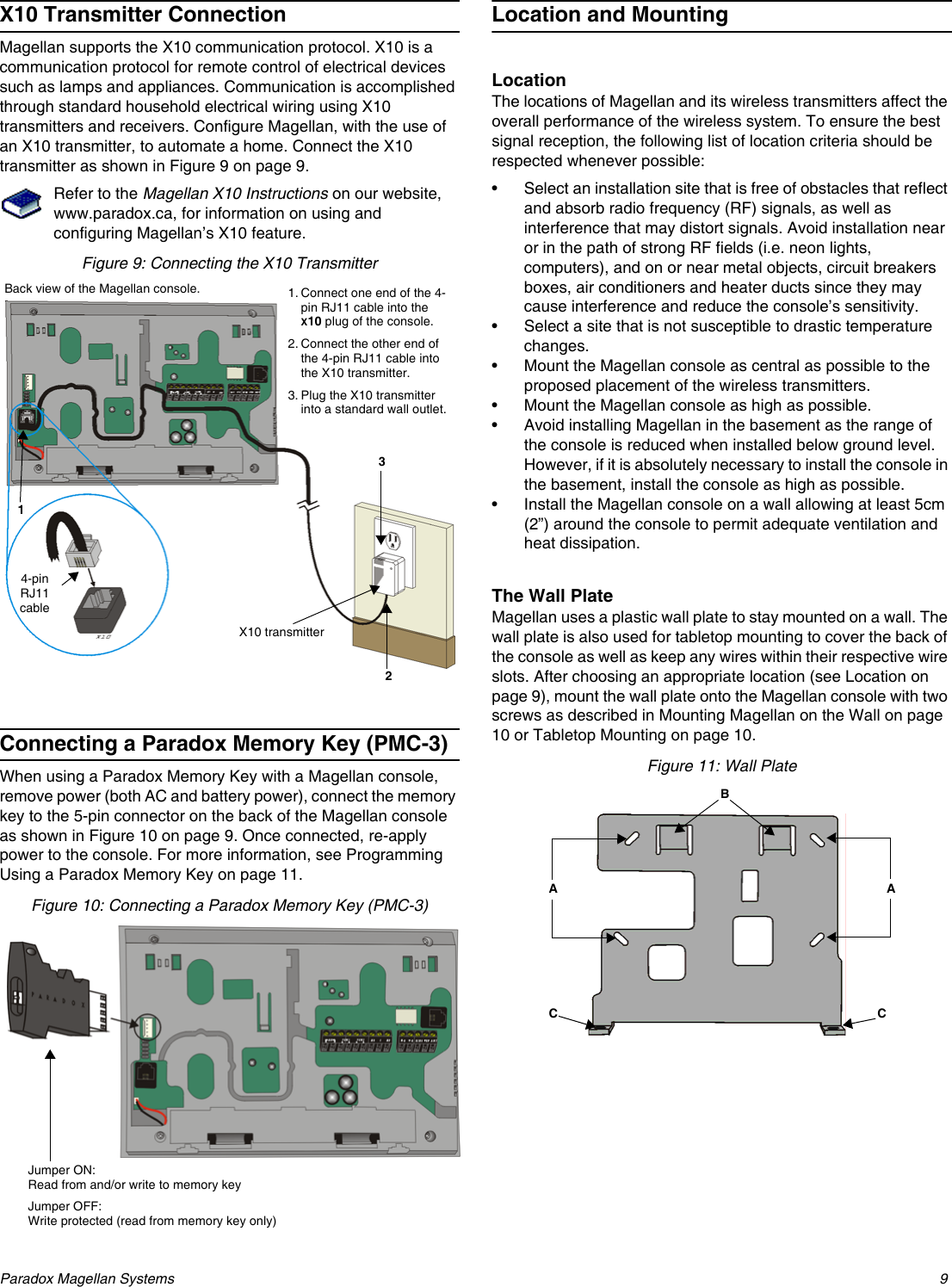
![8 Reference & Installation ManualHardwire Zone ConnectionsMagellan comes with two on-board hardwire zones. You can connect hardwire detection devices such as door contacts to Magellan’s zone terminals. Connect the detection devices as shown in Figure 6 on page 8. Please note the following:• Section [095] options [1] and [2] must be enabled in order to use the two on-board hardwire zones. See Zones 15 and 16 become Hardwire Zones on page 16 for more information.• After connecting the detection devices, the zones must be defined. See Zone Programming on page 13 for more information.• The hardwire zones follow the console’s EOL and tamper definitions.Though any hardwire detection device can be connected to Magellan’s on-board hardwire zone inputs, it is recommended that only devices that do not require a power source (i.e. standard door contacts) be connected. Since Magellan has no power supply, an external power supply would have to be connected in order to power hardwire detection devices that do require a power source.Figure 6: Hardwire Zone ConnectionsWinLoad ConnectionThe Magellan console can be programmed and monitored through the WinLoad Installer Upload/Download Software for Windows®. WinLoad allows for remote or on-site uploading and downloading using most standard modems. It also allows for advanced printing of reports and supports several languages simultaneously. Connect Magellan to a computer containing the WinLoad software as shown in Figure 7 on page 8.Refer to the WinLoad’s Online Help for more information on WinLoad.Figure 7: Connecting to WInLoadUIP-256 Universal In-Field Programmer ConnectionMagellan’s firmware can be upgraded locally using the UIP-256 Universal In-Field Programmer. The UIP-256 includes proprietary PC software, cables to interconnect Magellan and a PC, as well as two 9V batteries. Connect the UIP-256 as shown in Figure 8 on page 8.Refer to the Universal In-Field Programmer (UIP-256) Instructions for more information.Figure 8: Connecting the UIP-256Hardwire zone 2 (zone 16)Hardwire zone 1 (zone 15)Back view of the Magellan console.1K9EOL1K9EOL306 AdapterBack view of the Magellan console.StandardDB-9 cable(9-pin serial cable)Computer containing WinLoad software4- to 10-pin cable (supplied with the 306 Adapter)4-pin connector cable Connect the 10-pin cable of the UIP-256 to the 10-pin connector of the Magellan console.StandardDB-9 cable(9-pin serial cable)Download latest Magellan firmware from www.paradox.caBack view of the Magellan console.UIP-256Universal In-Field Programmer](https://usermanual.wiki/Paradox-Security-Systems/MG6060.Installation-guide-with-FCC-warnings/User-Guide-481305-Page-10.png)
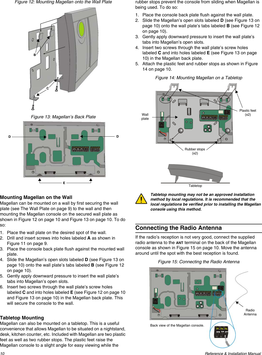
![Paradox Magellan Systems 11Programming MethodsWinLoad Installer Upload/Download SoftwareProgram the Magellan console remotely or on-site using the WinLoad Installer Upload/Download Software for Windows®. For more information, contact your local Paradox Distributor or visit our Web site at www.paradox.ca. If you are using the WinLoad software, you must program the features explained on page 33.Please refer to WinLoad’s Online Help for more information on using WinLoad.Programming Using the Built-in KeypadUse the built-in keypad to access Magellan’s programming mode. Use the supplied Magellan Programming Guide to keep track of which sections were programmed and how. To access programming mode:1. Press and hold the [0] key.2. Enter your [INSTALLER CODE] or [MAINTENANCE CODE].3. Enter the 3-digit [SECTION] you wish to program.4. Enter the required [DATA].There are two methods that can be used to enter data when in programming mode; Single Digit Data Entry and Feature Select Programming methods.Single Digit Data Entry MethodAfter entering programming mode, some sections will require that you enter decimal values from 000 to 255. Other sections will require that you enter hexadecimal values from 0 to F. The required data will be clearly indicated in this manual as well as in the Magellan Programming Guide. When entering the final digit in a section, Magellan will automatically save and advance to the next section. Table 1 (see below) shows the keys and their equivalent decimal and/or hexadecimal value.Table 1: Decimal and Hexadecimal Values* CK = Center keypadFeature Select Programming MethodAfter entering certain sections, eight options will be displayed where each option from [1] to [8] represents a specific feature or option. To manipulate the options: • Press the key corresponding to the desired option and the option number will appear in the LCD display. This means the option is ON. Press the key again to remove the digit from the LCD display, thereby, turning OFF the option. •Press the [*] key to set all eight options to OFF. Press the keys until the current section’s options are set. When the options are set, press the [#] key to save and advance to the next section.•Press the [*] key twice to exit without changing any data.Programming Using a Paradox Memory KeyThe Paradox Memory Keys (PMC-3) are very useful when multiple Magellan consoles are to be programmed identically.Rather then programming each console by entering its programming mode and then scrolling through programming sections, use a memory key to program each console. The programming of a console with a memory key takes approximately three seconds.There are two actions that can be performed with a memory key.Download Data to Destination ConsoleTo download the data of a memory key into a console:1. Remove power from the Magellan console (AC and battery) and connect the memory key to the 5-pin connector on the left side of the back of the console (see Figure 10 on page 9).2. Re-apply both AC and battery power to the console.3. Press the [OK] key and Magellan will begin downloading the data from the memory key.Copy Data to Memory Key from Source ConsoleTo copy the contents of a console into the memory key.1. Remove power from the Magellan console (AC and battery) and connect the memory key to the 5-pin connector on the left side of the back of the console (see Figure 10 on page 9).2. Re-apply both AC and battery power to the console.3. Press the [NEXT] key and then the [OK] key. Magellan will begin copying its data into the memory key.The installer code of the Magellan console used to download data to the memory key must be the same installer code programmed in the Magellan console that is to download the contents from the same memory key. If the installer codes do not match, the contents of the memory key cannot be downloaded into the receiving console.Example: The contents of the Magellan console A will be copied into memory key B. The installer code for console A is 111111. In order to download the contents of memory key B into the Magellan console C, the installer code programmed in console C must also be 111111.Key Value Key Value[1] 1[9] 9[2] 2[0] 0 (decimal)Space (Hexa decimal)[3] 3[1] CK*A (Hexadecimal only)[4] 4[2] CK*B (Hexadecimal only)[5] 5[3] CK*C (Hexadecimal only)[6] 6[4] CK*D (Hexadecimal only)[7] 7[5] CK*E (Hexadecimal only)[8] 8[6] CK*F (Hexadecimal only)](https://usermanual.wiki/Paradox-Security-Systems/MG6060.Installation-guide-with-FCC-warnings/User-Guide-481305-Page-13.png)
![12 Reference & Installation ManualUser CodesA person must be assigned to a user code in order to have access to Magellan. A user code defines the extent of a user’s access to the system and consists of a code # (PIN) and user options. Magellan supports one Installer code, one Maintenance code and up to 16 user codes (one System Master code and 15 User codes).User Code LengthSection [090]: Option [1]Option [1] OFF = 6-digit user codesOption [1] ON = 4-digit user codes (default)All user codes can be set to lengths of either 4 or 6 digits. When the 4-digit option is selected, entering a 4-digit code will allow access. Using the 6-digit option, entering 6 digits is required to allow access.If the User Code Length is changed from 4 digits to 6 digits when user codes have already been programmed, the console will automatically add the last 2 digits by using the first 2 digits. For example, if the access code is 1234 and you switch to 6 digits, the code will become 123412. Be sure to verify the access codes after switching from 4-digit to 6-digit access codes. When switching from 6 digits to 4 digits, the console will simply remove the final 2 digits of the access code. For example, 123456 will become 1234.Installer CodeSection [181]; Default = 000000The Installer code is used to enter the console's programming mode (see Programming Using the Built-in Keypad on page 11), which allows you to program all the features, options and commands of the Magellan console. The Installer code can be 4- or 6-digits in length (see User Code Length on page 12) where each digit can be any value from 0 to 9. The Installer code cannot be used to program any user code. To change the Installer code:1. Access the installer programming mode (page 11).2. Enter section [181].3. Enter a new [4- OR 6-DIGIT INSTALLER CODE].OR1. Press [MENU] + [4] + [INSTALLER CODE] + [8] + [NEW CODE].Maintenance CodeSection [182]; Default = 111111The Maintenance code is similar to the Installer code. It can be used to enter the console’s programming mode (see Programming Using the Built-in Keypad on page 11), which allows you to program all features, options and commands except for the console’s communication settings (sections [100] to [154]) as well as any user code. The Maintenance code can be 4 or 6 digits in length (see User Code Length on page 12) where each digit can be any value from 0 to 9.To change the Maintenance code:1. Access the installer programming mode (page 11).2. Enter section [182].3. Enter a new [4- OR 6-DIGIT MAINTENANCE CODE].OR1. Press [MENU] + [4] + [INSTALLER CODE] + [8] + [NEW CODE].System Master CodeWith the System Master code a user can use any arming method and can program any user’s (from 1 to 16) Access Code. The System Master code can be 4 or 6 digits in length (see User Code Length on page 12), where each digit can be any digit from 0 to 9. The System Master code cannot be changed by the installer or maintenance code, but it can be reset to default.Lock System Master CodeSection [090]: Option [3]Option [3] OFF =System Master code unlocked (default)Option [3] ON =System Master code lockedWith section [090] option [3] enabled, the System Master code can only be changed or deleted through WinLoad or a power down reset.Reset System Master CodeSection [200]Enter section [200] to reset the System Master code to default (1234/123456).Make sure that the Lock System Master Code feature (section [090] option [3]) is disabled.Duress CodeSection [090]: Option [4]Option [4] OFF = Duress code disabled (default)Option [4] ON = User code 016 becomes a duress codeWith this feature enabled, user code 016 becomes a Duress code. When forced to arm or disarm their system, users can enter a Duress code (user code 016) to arm or disarm the system which can immediately transmit a silent alert to the Central Station, transmitting the duress report code programmed in section [140] (page 25).Installer Code Used to program all console settings except User codes and Remote ControlsMaintenance Code Identical to the Installer code except that the code cannot program dialer options or perform a software reset.System Master CodeUser Code 001Provides access to the following Magellan user features: language, voice and utility reporting, delays and tones, zone labels, system tests. Arm and disarm using any method as well as program User Codes.15 User CodesUser Codes 002 to 016Can arm and disarm the system.](https://usermanual.wiki/Paradox-Security-Systems/MG6060.Installation-guide-with-FCC-warnings/User-Guide-481305-Page-14.png)
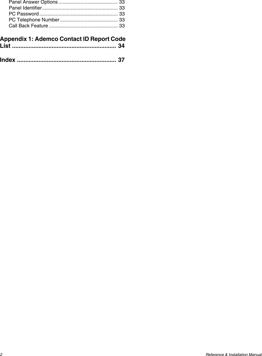
![Paradox Magellan Systems 13Zone ProgrammingMagellan supports up to 16 wireless zones where each zone can be configured with a different zone definition and option. Each zone can also have a voice label recorded for it. Magellan’s zones can be programmed using section programming or through the Installer menu.See Quick Setup on page 4 for more information on zone programming using the Installer menu.Zone Programming OverviewAfter assigning and setting up your wireless transmitters, define the associated zone's parameters. The zone parameters define the type of zone and how the control panel will react when an alarm condition occurs on that zone. These zone parameters are programmed into one section as detailed in Figure 16 on page 13.Figure 16: Magellan Zone Programming OverviewZone DefinitionsSections [001] to [016] represent zones 1 through 16 respectively, where the first three digits in each of these sections represents the zone's definition. To disable a zone, enter 000 and then press the [#] key. There are 15 available Zone Definitions, which are described as follows:Entry Delay 1Sections [001] to [016]: Zones 1 to 16, 3-digit # = 001When the system is armed and a zone defined with Entry Delay 1 opens, the console will generate an alarm after the programmed Entry Delay 1 Timer elapses. This is to provide users with enough time to enter the protected area and disarm the system. Entry Delay zones are commonly used at the entry/exit points of the protected area (i.e. front/back door, garage, etc.). Using different Entry Delays (see Entry Delay 2 below) is useful when, for example, one entry point requires a longer delay than the other entry point.Entry Delay 1 TimerSection [060]: 001 to 255 seconds; 000 = Disabled; Default = 45 secondsEnter the desired 3-digit delay value from 000 to 255 seconds into section [060] to program the Entry Delay 1 Timer.Entry Delay 2Sections [001] to [016]: Zones 1 to 16, 3-digit # = 002Entry Delay 2 zones are identical to the Entry Delay 1 zones (see Entry Delay 1 on page 13), except it uses a separate Entry Delay Timer.Entry Delay 2 TimerSection [061]: 001 to 255 seconds; 000 = Disabled; Default = 45 secondsEnter the desired 3-digit delay value from 000 to 255 seconds into section [061] to program the Entry Delay 2 Timer.Follow ZonesSections [001] to [016]: Zones 1 to 16, 3-digit # = 003When an armed Follow zone opens, the console will immediately generate an alarm unless an Entry Delay zone opens first as described in the situations below:• If an armed Follow zone opens after an Entry Delay zone opens, the console waits until the Entry Delay Timer has elapsed before generating an alarm.• If an armed Follow zone opens after more than one Entry Delay zone opens, the console will wait until the Entry Delay Timer of the zone that opened first has elapsed.This feature is commonly used when a motion detector is protecting the area occupied by the entry point keypad. This will prevent the motion detector from causing an alarm when a user enters through the entry point to disarm the system.Press and hold the [0] keyEnter your [INSTALLER CODE] or [MAINTENANCE CODE]Enter 3-digit [SECTION][001] = Zone 1[002] = Zone 2[003] = Zone 3[004] = Zone 4[005] = Zone 5[006] = Zone 6[007] = Zone 7[008] = Zone 8[009] = Zone 9[010] = Zone 10[011] = Zone 11[012] = Zone 12[013] = Zone 13[014] = Zone 14[015] = Zone 15[016] = Zone 16Zone Definition000 = Zone disabled001 = Entry Delay 1002 = Entry Delay 2003 = Follow004 = Follow / Stay005 = Instant006 = Instant / Stay007 = Instant Fire008 = Delayed Fire Zone009 = 24hr Burglary010 = 24hr Hold-up011 = 24hr Buzzer012 = 24hr Gas013 = 24hr Heat014 = 24hr Water015 = 24hr FreezeZone Options*[1] = Auto-zone Shutdown (default)[2] = Zone Bypass (default)[3] = Future use[6] = Intellizone[7] = Delay alarm transmission[8] = Force Zone[4] [5] Zone Alarm TypeOFF OFF Audible alarm (steady)OFF ON Audible alarm (pulsed)ON OFF Silent alarmON ON Generate report onlyEnter 3-digit [ZONE DEFINITION]Use feature select method (p. 11) to select the [ZONE OPTIONS]Press the [#] key to saveKeypad beeps twice* Available through Section Programming only.](https://usermanual.wiki/Paradox-Security-Systems/MG6060.Installation-guide-with-FCC-warnings/User-Guide-481305-Page-15.png)
![14 Reference & Installation ManualFollow/Stay ZonesSections [001] to [016]: Zones 1 to 16, 3-digit # = 004Follow/Stay zones function as follows:• All zones defined as Follow/Stay zones become Follow zones (refer to Follow Zones on page 13) when the Magellan system is Regular armed.• All zones defined as Follow/Stay zones become Stay zones when the Magellan system is Stay or Instant armed.Instant ZonesSections [001] to [016]: Zones 1 to 16, 3-digit # = 005When an armed Instant zone opens, the console immediately generates an alarm. Instant zones are commonly used for windows, patio doors, skylights and other perimeter type zones.Instant/Stay ZonesSections [001] to [016]: Zones 1 to 16, 3-digit # = 006Instant/Stay zones function as follows:• All zones defined as Instant/Stay zones become Instant zones (refer to Instant Zones on page 14) when the Magellan system is Regular armed.• All zones defined as Instant/Stay zones become Stay zones when the Magellan system is Stay or Instant armed.Standard 24Hr. Fire ZonesSections [001] to [016]: Zones 1 to 16, 3-digit # = 007Whenever a Standard 24Hr. Fire Zone opens, whether it is armed or disarmed, the console will generate the following:• The console can send the corresponding Alarm Report Code from sections [187] to [190]. • Alarms are always audible regardless of other settings. Fire alarms generate an intermittent (pulsed) bell/siren output signal as shown in Figure 17 on page 14.Figure 17: Bell/Siren Output during a Fire AlarmDelayed Fire ZonesSections [001] to [016]: Zones 1 to 16, 3-digit # = 008When a Delayed 24Hr. Fire Zone opens, whether it is armed or disarmed, the console will react as shown in Figure 18 on page 14. Delayed 24Hr. Fire Zones are commonly used in residential homes where a smoke detector often generates false alarms (i.e. burning bread, etc.).Figure 18: Delayed Fire Zone24Hr. Burglary ZonesSections [001] to [016]: Zones 1 to 16, 3-digit # = 009Whenever a 24Hr. Burglary Zone opens, whether the system is armed or disarmed, the console will immediately generate an alarm.24Hr. Hold-up ZonesSections [001] to [016]: Zones 1 to 16, 3-digit # = 010When a 24Hr. Hold-up zone opens, whether it is armed or disarmed, the console will immediately generate an alarm. The SIA FSK reporting format includes specific report codes to identify the alarm as a Hold-up alarm.24Hr. Buzzer ZonesSections [001] to [016]: Zones 1 to 16, 3-digit # = 011This zone definition is particularly useful when a user wishes to be notified when something such as a safe or locker within the home has been accessed (i.e. a child accessing a valuable collection). This zone definition functions as follows: • Whenever a 24Hr. Buzzer Zone opens, whether the console is armed or disarmed, the console sets off the keypads’ buzzers to indicate that the zone was breached. • The console will report the alarm, but will not enable the bell/siren output. • Enter any valid access code on the keypad to stop the buzzer.](https://usermanual.wiki/Paradox-Security-Systems/MG6060.Installation-guide-with-FCC-warnings/User-Guide-481305-Page-16.png)
![Paradox Magellan Systems 1524Hr. Gas ZonesSections [001] to [016]: Zones 1 to 16, 3-digit # = 012When a 24Hr. Gas zone opens, whether it is armed or disarmed, the console will immediately generate an alarm. The SIA FSK reporting format includes specific report codes to identify the alarm as a Gas alarm.24Hr. Heat ZonesSections [001] to [016]: Zones 1 to 16, 3-digit # = 013When a 24Hr. Heat zone opens, whether it is armed or disarmed, the console will immediately generate an alarm. The SIA FSK reporting format includes specific report codes to identify the alarm as a Heat alarm.24Hr. Water ZonesSections [001] to [016]: Zones 1 to 16, 3-digit # = 014When a 24Hr. Water zone opens, whether it is armed or disarmed, the console will immediately generate an alarm. The SIA FSK reporting format includes specific report codes to identify the alarm as a Water alarm.24Hr. Freeze ZonesSections [001] to [016]: Zones 1 to 16, 3-digit # = 015When a 24Hr. Freeze zone opens, whether it is armed or disarmed, the console will immediately generate an alarm. The SIA FSK reporting format includes specific report codes to identify the alarm as a Freeze alarm.Zone OptionsSections [001] to [016] represent zones 1 through 16 respectively as demonstrated in Figure 16 on page 13. After entering the 3-digit Zone Definition (see Zone Definitions on page 13), select one or more of the following Zone Options by using the Feature Select Programming Method (see page 11):Auto-zone ShutdownSections [001] to [016]: Zones 1 to 16; Option [1]Option [1] OFF =Auto-zone Shutdown disabledOption [1] ON =Auto-zone Shutdown enabled (default)If, in a single armed period, the number of alarms generated by a zone with the Auto Zone Shutdown option enabled exceeds the number defined by the Auto Zone Shutdown Counter, the console will no longer generate an alarm for that zone. The Auto Zone Shutdown Counter resets every time the system is armed.Auto-zone Shutdown CounterSection [067]: 001 to 015 alarms; 000 = Disabled; Default = 5 alarmsEnter the desired limit into section [067] to program the Auto-zone Shutdown Counter.Bypass OptionSection [001] to [016]: Zones 1 to 16; Option [2]Option [2] OFF =Bypass option disabledOption [2] ON =Selected zone is bypass enabled (default)When a user uses the Bypass Programming feature, only zones with the Bypass option enabled can be programmed as bypassed.Fire zones cannot be programmed with the Bypass option because the console will not bypass a Fire zone.Alarm TypesSections [001] to [016]: Zones 1 to 16; Options [4] and [5]When an alarm condition occurs, the console can be programmed to react as shown in Table 2 on page 15.Table 2: Alarm Type OptionsThe Alarm Type options cannot be programmed for Fire zones. Fire zones are automatically programmed with an audible pulsed alarm. This cannot be altered.IntellizoneSections [001] to [016]: Zones 1 to 16; option [6]Option [6] OFF =Intellizone disabled (default)Option [6] ON =Intellizone enabledThis feature reduces the possibility of false alarms. When a zone with the Intellizone option opens, the console does not immediately generate an alarm. First it triggers the Intellizone Delay Timer. If any of the following conditions occur during this period, the panel will generate an alarm:• During the Intellizone Delay, a second zone has caused an alarm.• During the Intellizone Delay, the zone in alarm has restored (closed) and re-occurred (opened).• The zone in alarm is still open after the Intellizone Delay has elapsed.Options Description[4] [5]OFF OFF Audible steady alarm (default)When the conditions for an alarm have been met, the control panel can transmit the appropriate Zone Alarm report code (see page 24) and provides a steady output for the on-board siren.OFF ON Audible pulsed alarmWhen the conditions for an alarm have been met, Magellan can transmit the appropriate Zone Alarm report code (see page 24) and provides a pulsed output (see Figure 17 on page 14) for the on-board siren.ON OFF Silent alarmWhen the conditions for an alarm are met, the control panel can transmit the appropriate Zone Alarm report code (see page 24) and will not activate the control panel’s bell output. The appropriate ARM or STATUS LED on the keypads will flash to indicate an alarm and the user will still have to disarm the system.ON ON Report onlyWhen the conditions for an alarm have been met, the control panel can transmit the appropriate Zone Alarm report code (see page 24). The system will not have to be disarmed.](https://usermanual.wiki/Paradox-Security-Systems/MG6060.Installation-guide-with-FCC-warnings/User-Guide-481305-Page-17.png)
![16 Reference & Installation ManualIntellizone Delay TimerSection [065]: 010 to 255 seconds; Default = 48 secondsEnter the desired 3-digit value into section [065] to program the Intellizone Delay Timer.Delay Before Alarm Report Code TransmissionSections [001] to [016]: Zones 1 to 16; option [7]Option [7] OFF =Delay alarm transmission disabled (default)Option [7] ON =Delay alarm transmission enabledThis feature is commonly used with Entry Delay zones to reduce false alarms created by new users who may not disarm the system in time. This feature works as follows: • When an alarm condition occurs on a zone with this option enabled, the console enables the bell/siren output, but does not report the alarm to the central station until the end of the Alarm Before Transmission Delay. • During this period, disarming the system disables the bell/siren output and cancels the report code transmission. Alarm Transmission DelaySection [075]: 001 to 255 seconds; 000 = Disabled; Default = 0 secondsEnter the desired 3-digit delay value into section [075] to program the Alarm Transmission Delay.Remote Panic Disarm Lock DelaySection [078]: 001 to 255 seconds; 000 = Disabled; Default = 20 secondsWhen a panic alarm is generated through the use of a remote control, the system cannot be disarmed by remote control during the Remote Panic Disarm Lock Delay.Enter the desired 3-digit delay value into section [078] to program the Remote Panic Disarm Lock Delay.Force ZonesSections [001] to [016]: Zones 1 to 16; Option [8]Option [8] OFF =Force zone disabledOption [8] ON =Selected zone is Force enabled (default)Any open Force zones at the time of arming will be considered deactivated by the console. If during this period a deactivated zone is closed, the console will revert that zone to active status. Consequently, the console will generate an alarm if the zone is breached.Fire zones cannot be programmed with the Force Zone option because the console will not bypass a Fire zone when the system is being Force armed.Stay Delay ZonesSection [094]: Options [1]Option [1] OFF =Stay Delay zone disabled (default)Option [1] ON =Stay Delay zone enabledWhen a Stay Delay zone is armed using the Stay or Instant arming methods and the zone is triggered, an alarm will not generate until the programmed Stay Delay elapses. A zone defined as Stay Delay 1 follows the Entry Delay 1 Timer of its assigned partition. Likewise, a zone defined as Stay Delay 2 follows the Entry Delay 2 Timer of its assigned partition. To program the Entry Delay Timers, refer to Entry Delay 1 and Entry Delay 2 on page 13. Zones 15 and 16 become Hardwire ZonesSection [095]: Options [1] and [2]Option [1] OFF = Wireless zone 15 remains unchanged (default)Option [1] ON = Wireless zone 15 uses the on-board hardwire zone input 1Option [2] OFF = Wireless zone 16 remains unchanged (default)Option [2] ON = Wireless zone 16 uses the on-board hardwire zone input 2The Magellan console comes with two on-board zone inputs, hardwire zone inputs 1 and 2. Section [095] options [1] and [2] allow you to convert zones 15 and 16 from wireless to hardwire by allowing you to connect hardwire detection devices (i.e. door contact) to zone inputs 1 and 2.• With section [095] option [1] ON, zone 15 is connected to zone input 1. • With section [095] option [2] ON, zone 16 is connected to zone input 2.EOL (End-Of-Line) ZonesSection [095]: Option [3]Option [3] OFF = Hardwire zones 1 & 2 do not require EOL resistors (default)Option [3] ON = Hardwire zones 1 & 2 require EOL resistorsThis feature only applies to Magellan’s on-board zone inputs. Section [095] options [1] and/or [2] (see Zones 15 and 16 become Hardwire Zones on page 16) must be ON in order to use this feature.If the hardwire detection devices connected to Magellan’s zone inputs 1 and 2 have input terminals that require 1K9 end of line resistors, enable (ON) section [095] option [3]. For details on using EOL resistors, refer to page 8.](https://usermanual.wiki/Paradox-Security-Systems/MG6060.Installation-guide-with-FCC-warnings/User-Guide-481305-Page-18.png)
![Paradox Magellan Systems 17Wireless ProgrammingThe Magellan system supports up to 16 wireless zones and two wireless doorbells. These wireless zones are monitored using transmitters such as wireless detectors and door contacts. The Magellan console only supports the Paradox Magellan series of wireless transmitters. The programming of the transmitters is accomplished in two steps:1. Assign the wireless transmitter to Magellan.2. Program the wireless zone.Assigning Wireless Zone TransmittersSections [021] to [036]: Zones 1-16; Wireless Transmitters 1-16Sections [021] to [036] represent zones 1 to 16. A wireless transmitter assigned to a section ([021] to [036]) will be assigned to the zone represented by the section.For example, a wireless transmitter assigned to section [025] will be assigned to zone 5. To assign a wireless transmitter:1. Access the installer programming mode (page 11).2. Enter the [SECTION] corresponding to the desired zone.3. Enter the 6-digit [SERIAL NUMBER] of the wireless transmitter.The serial number is located on the inside of the wireless transmitter.The wireless transmitters must be activated once having been assigned to the Magellan console. To activate a transmitter, insert the batteries and close the cover. To ensure proper synchronization between the console and the transmitter, open and close the zone corresponding to the transmitter.Are the zones that have wireless transmitters assigned to them programmed? See Zone Definitions on page 13 and Zone Options on page 15.Wireless transmitters can also be assigned through the Installer menu. Press [MENU] + [4] + [INSTALLER CODE] + [6]. Select the zone you wish to assign the transmitter to, press [OK], open the cover of the transmitter and then close the cover. The transmitter has been assigned. Refer to the Magellan Quick Setup for more information on the Installer menu and the assignment of the wireless transmitters.Assigning Wireless Doorbells to the ConsoleSections [058] and [059]: Wireless Doorbells 1 and 2Magellan supports the use of two wireless “doorbells”. By connecting a pushbutton to the Universal Transmitter inputs of a Magellan Wireless Door Contact (MG-DCT1), the MG-DCT1 will transmit a signal to Magellan whenever the pushbutton is pressed. Magellan will in turn become a “doorbell” and play a predetermined tone (see Wireless Doorbell Tones on page 17).Please refer to the appropriate Magellan Wireless Door Contact Instruction for information on the installation and configuration of the wireless door contact.To assign a wireless doorbell:1. Access the installer programming mode (page 11).2. Enter the [SECTION] corresponding to the desired doorbell.3. Enter the 6-digit [SERIAL NUMBER] of the MG-DCT1.Wireless Doorbell TonesSection [096]: Options [1] to [4]Options [1] and [2] = Set tone for wireless doorbell 1Options [3] and [4] = Set tone for wireless doorbell 2Section [096] options [1] to [4] set the tones that will be played when Magellan receives a signal from either wireless doorbell 1 or 2 or both. Magellan comes with four tones. Refer to Table 3 on page 17 to set the desired tone.Table 3: Wireless Doorbell TonesDeleting Assigned Wireless TransmittersSections [021] to [036]: Zones 1-16; Wireless Transmitters 1-16Sections [058] and [059]: Wireless Doorbells 1 and 2To delete an assigned wireless transmitter:1. Access the installer programming mode (page 11).2. Enter the [SECTION] corresponding to the desired zone or doorbell.3. Press the [0] key six times to clear the wireless transmitter’s serial number.Viewing Wireless Transmitter Signal StrengthSections [021] to [036]: Zones 1-16; Wireless Transmitters 1-16Sections [058] and [059]: Wireless Doorbells 1 and 2Once wireless transmitters have been assigned to the Magellan console, the signal strength of each transmitter can be verified in sections [021] to [036] (zones 1 to 16 respectively) and sections [058] and [059] (wireless doorbells 1 and 2 respectively). Each section represents the signal strength viewer for the wireless transmitter assigned to the corresponding zone. For example, section [021] is the viewer for the wireless transmitter assigned to zone 1 and section [036] is the viewer for the wireless transmitter assigned to zone 16. Section [096] - Options [1] and [2] Doorbell Tone #Option [1] OFF / Option [2] OFF (Doorbell 1) Tone 1 (default)Option [1] OFF / Option [2] ON (Doorbell 1) Tone 2Option [1] ON / Option [2] OFF (Doorbell 1) Tone 3Option [1] ON / Option [2] ON (Doorbell 1) Tone 4Section [096] - Options [3] and [4] Doorbell Tone #Option [3] OFF / Option [4] OFF (Doorbell 2) Tone 1Option [3] OFF / Option [4] ON (Doorbell 2) Tone 2 (default)Option [3] ON / Option [4] OFF (Doorbell 2) Tone 3Option [3] ON / Option [4] ON (Doorbell 2) Tone 4](https://usermanual.wiki/Paradox-Security-Systems/MG6060.Installation-guide-with-FCC-warnings/User-Guide-481305-Page-19.png)
![18 Reference & Installation ManualThe signal strength is displayed using two terms:• “Good”: This is an average reading and is acceptable.• “Weak”: This is the weakest reading. The transmitter should be moved to another location. Sometimes moving the transmitter by a small amount will greatly increase the signal reception.To view the signal strength of a wireless transmitter:1. Access the installer programming mode (page 11).2. Enter the [SECTION] corresponding to the desired zone or doorbell.3. The LCD will display either “Good” or “Weak” on the screen.When performing a signal strength test, Magellan also displays the noise level surrounding each of the transmitters. “Low” refers to a low level of noise while “High” refers to a noisy environment.The signal strength can also be verified by performing a system test. See Quick Setup on page 4 for more information.Assigning Remote ControlsSections [041] to [056]: Users 1 to 16; Remote Controls 1 to 16The Magellan console accepts up to 16 fully programmable remote controls. Every user code can have one remote control assigned to it.To assign a remote control:1. Press [MENU] + [4] + [2].Programming the Remote Control’s ButtonsSections [161] to [176]: Users 1 to 16; Remote Controls 1 to 16Sections [161] to [176] represent the remote controls assigned to user codes 1 to 16 (see Table 4 on page 18).The remote control will transmit a signal for only 1 second when a button is pressed. This is done to conserve the remote control’s batteries.Though remote controls can be assigned by the System Master, the remote control’s buttons are programmed by the installer.Each remote control can be programmed to perform up to 5 different actions. Each digit in sections [161] to [176] represents a button or combination of buttons (see Table 4 on page 18).To program a remote control’s buttons:1. Access the installer programming mode (page 11).2. Enter the [SECTION] (sections [161] to [176]) corresponding to the desired remote control.3. Enter the [HEXADECIMAL VALUE] (0 to D) of the desired button option from Table 20 (page 19).If you do not wish to program all the buttons or button combinations, press the [#] key at any time to save and exit.If you enable any Panic button options, you must enable the Panic options in the control panel (refer to Panic Alarms on page 23).Table 4: Remote Control Button ProgrammingFigure 19: Remote Control Button IdentificationSection #Data (refer to Table 20 on page 19) User #[161] _____/_____/_____/_____ Remote Control 1 001[162] _____/_____/_____/_____ Remote Control 2 002[163] _____/_____/_____/_____ Remote Control 3 003[164] _____/_____/_____/_____ Remote Control 4 004[165] _____/_____/_____/_____ Remote Control 5 005[166] _____/_____/_____/_____ Remote Control 6 006[167] _____/_____/_____/_____ Remote Control 7 007[168] _____/_____/_____/_____ Remote Control 8 008[169] _____/_____/_____/_____ Remote Control 9 009[170] _____/_____/_____/_____ Remote Control 10 010[171] _____/_____/_____/_____ Remote Control 11 011[172] _____/_____/_____/_____ Remote Control 12 012[173] _____/_____/_____/_____ Remote Control 13 013[174] _____/_____/_____/_____ Remote Control 14 014[175] _____/_____/_____/_____ Remote Control 16 015[176] _____/_____/_____/_____ Remote Control 16 016++++++++++++++++MG-REM1The button of the MG-REM1 remote control has been permanently programmed to disarm the system. The button’s functionality cannot be altered.The , and button combinations do not function with the MG-REM1 remote control.+ + +](https://usermanual.wiki/Paradox-Security-Systems/MG6060.Installation-guide-with-FCC-warnings/User-Guide-481305-Page-20.png)
![Paradox Magellan Systems 19Figure 20: Remote Control Button Options* = Hexa values A to F are keys [1] to [6] from Magellan’s Center Keypad.† = The panic feature (section [091] options [1] to [3]; see page 23) must be enabled in order for this to work.Figure 21: Replacing the Remote Control’s BatteryHexa Value Description Hexa Value Description0Button disabled 8Panic 1†1Regular arming 9Panic 2†2Stay arming A* Panic 3†3Instant arming B* PGM Activation (Event Group #07 - Refer to the Magellan Programming Guide)4Force arming C* PGM Activation (Event Group #08 - Refer to the Magellan Programming Guide)5Future use D* Turn FM radio ON/OFF6Future use E* FM radio memory scan7Future use F* Paramedic alarmInset 1: Removing the Battery Inset 2: Inserting the New BatteryStep 1Step 2WARNING!Damage to the metal prongs may occur if the battery is not inserted correctly.Battery type: One 3V lithium battery (CR2032)How to replace the battery:1. Remove the two screws from the back of the remote control and remove the back cover.2. Slide a teflon screwdriver, or any plastic device, under the battery to remove it from the battery compartment (see Inset 1 below). Avoid using metal as it may cause a short in the board.3. Insert the new battery as shown in Inset 2 below. The negative side of the battery is inserted face down.4. Set the back cover in place and fasten it with the two screws.](https://usermanual.wiki/Paradox-Security-Systems/MG6060.Installation-guide-with-FCC-warnings/User-Guide-481305-Page-21.png)
![20 Reference & Installation ManualArming and DisarmingRegular Arming Switches to Stay ArmingSection [092]: Option [4]Option [4] OFF = Switch to Stay arming disabled (default)Option [4] ON = Switch to Stay arming enabledIf a user Regular arms the system, but does not exit through (open and close) an Entry Delay zone during the Exit Delay, the console can be programmed to switch from Regular arming to Stay arming.Regular Arming Switches to Force ArmingSection [092]: Option [5]Option [5] OFF = Regular arming switches to Force arming disabledOption [5] ON = Regular arming switches to Force arming enabled (default)With this feature enabled, the console will always Force arm instead of Regular arm when a valid User code is entered. In installations where the User must always Force arm when leaving the protected area, this feature allows users to Force arm after entering their User code.Stay Arming Switches to Force ArmingSection [092]: Option [6]Option [6] OFF = Stay arming switches to Force arming disabled (default)Option [6] ON = Stay arming switches to Force arming enabledWith this feature enabled, the console will always Force arm and Stay arm when a valid User code is entered even if there are perimeter zones open.Timed Auto-ArmingSection [092]: Option [1]Option [1] OFF = Timed Auto-arming disabled (default)Option [1] ON = Timed Auto-arming enabledThe Magellan system can be programmed to arm every day at the time specified by the Auto-arm Timer (see Auto-arm Timer on page 20). The following also apply:• The Auto-arming options (Auto-Arming Options on page 20) determine the arming method. • Any open zones detected when the system is Auto-armed will be bypassed regardless of their definition (except 24hr. zones). • The console will enter a 60-second Exit Delay period before arming the system. At this point, Auto-arming can be cancelled by entering a valid access code. • Once the system has successfully armed, the console can transmit the Timed Auto-Arming report code programmed in section [124]. Example: To automatically arm the system everyday at 6:15PM, enable section [092] option [1] to activate Timed Auto-arming and then key in 18:15 into section [085].Auto-arm TimerSection [085]Program the time (use the 24-hour clock i.e. 6:30PM = 18:30) that you wish the console to attempt to arm the system and/or send the Late to Close report code.No Movement Auto-ArmingSection [092]: Option [2]Option [2] OFF = No Movement Auto-arming disabled (default)Option [2] ON = No movement Auto-arming enabledIf no movement occurs in a zone's protected area for the period specified by the No Movement Timer (see below), the console can automatically arm the system.• The Auto-arming option (Auto-Arming Options on page 20) determines the system's arming method. • Any open zones detected when the system is Auto-armed will be bypassed regardless of their definition (except 24hr. zones). • Upon arming, the console will transmit the No Movement report code if programmed in section [124]. • Regardless of whether the system was successfully armed or not, the console will always transmit the No Movement report code if programmed in section [124]. • If No Movement Auto-arming is disabled, the console will still send the No Movement report code at the time specified by the No Movement Timer. Example: To arm the system whenever there is no movement for a period of 4 hours, enable section [092] option [2] (No Movement Auto-arming) and then in section [064], enter 016 (16 x 15min. = 240min. = 4 hours).No Movement TimerSection [064]: 001 to 255 x 15 minutes; 000 = Disabled; Default = 000Program the interval of time without movement you wish the console to wait before arming and/or sending the No Movement report code. If No Movement Auto-arming is disabled, the console can still send the No Movement report code when no movement has been detected for the period specified by the No Movement Timer.Auto-Arming OptionsSection [092]: Option [3]Option [3] OFF = Auto-arm system using Regular arm (default)Option [3] ON = Auto-arm system using StayWhen using Timed Auto-arming (page 20) or No Movement Auto-Arming (page 20), the console can Regular or Stay arm the system.](https://usermanual.wiki/Paradox-Security-Systems/MG6060.Installation-guide-with-FCC-warnings/User-Guide-481305-Page-22.png)
![Paradox Magellan Systems 21One-Touch ArmingSection [092]: Options [7] and [8]Option [7] OFF = One-touch Regular/Force arming disabledOption [7] ON = One-touch Regular/Force arming enabled (default)Option [8] OFF = One-touch Stay arming disabledOption [8] ON = One-touch Stay arming enabled (default)The One-touch arming features allow users to arm the system without having to enter any access codes. To arm the system, press and hold the appropriate key for approximately 2 seconds.Exit DelaySection [062]: 001 to 255 seconds; 000 = disabled; Default = 60 secondsThe exit delay determines the amount of time a user has to leave the protected area before Magellan arms the system. The exit delay applies to all zones (except 24Hr zones) in the system. Program the exit delay from 001 to 255 seconds.Bell Squawk on Arm/Disarm with Remote ControlSection [093]: Option [3]Option [3] OFF = Bell squawk disabledOption [3] ON = Bell squawk enabled (default)When option [3] is enabled (ON), the siren will squawk once upon arming with a remote control and twice upon disarming with a remote control.No Exit Delay when Arming with Remote ControlSection [093]: Option [4]Option [4] OFF = Provides exit delay when arming with remote control (default)Option [4] ON = No exit delay when arming with remote controlWhen option [4] is enabled (ON), the console cancels the Exit Delay (arms instantly) when the system is armed with a remote control. When disabled, the Exit Delay timer will start when the system is armed with a remote control.Exit Delay TerminationSection [093]: Option [6]Option [6] OFF = Exit delay termination feature disabledOption [6] ON = Exit delay termination feature enabled (default)When option [6] is enabled (ON), the console will reduce the exit delay to 10 seconds when an Entry Delay zone (see Exit Delay on page 21) is opened and closed during the exit delay.Example: 15 seconds into a 45 second exit delay, an Entry Delay zone opens and closes. The remaining 30 seconds is reduced to 10 seconds.Follow Zone Switches to Entry Delay 2Section [093]: Option [7]Option [7] OFF = Follow zone triggers an alarm (default)Option [7] ON = Follow zone follows Entry delay 2 when openedWhen option [7] is enabled (ON) and an Entry Delay 1 zone is bypassed, an armed Follow zone that opens without an entry delay being triggered will switch to the entry delay 2 timer.Example: Zone 1 is an Entry Delay zone and zone 2 is a Follow zone protecting the area where the keypad is installed. The system is armed but zone 1 is bypassed. With option [7] enabled, zone 2 will switch to and wait for the entry delay 2 timer to elapse before triggering an alarm.Closing Delinquency TimerSection [080]: 001 to 255 days; 000 = Disabled; Default = 000The Magellan console will verify when the system was last armed at midnight of every day. If the last time the system was armed is greater than the programmed Closing Delinquency timer, the console will transmit a Closing Delinquency report code (page 25) to the central monitoring station. Enter a value from 001 to 255 days into section [080] to program the Closing Delinquency timer. Enter 000 to disable the timer.](https://usermanual.wiki/Paradox-Security-Systems/MG6060.Installation-guide-with-FCC-warnings/User-Guide-481305-Page-23.png)
![22 Reference & Installation ManualAlarm OptionsBell Cut-off TimerSection [063]: 001 to 255 minutes; 000 = Disabled; Default = 4 minutesAfter an audible alarm, the siren will stop upon disarming of the system or when the Bell Cut-Off timer has elapsed, whichever comes first.Wireless Transmitter Supervision OptionsSection [094]: Options [6] and [7]This feature determines how the Magellan console will react to a Supervision Loss trouble. Table 5 shows the different supervision loss combinations available and how the system will react when armed or disarmed.Table 5: Wireless Transmitter Supervision OptionsSupervision Bypass OptionsSection [094]: Option [8]Option [8] OFF =No Supervision Loss if detected on a Bypassed Zone (default)Option [8] ON =Generate Supervision Loss if detected on a Bypassed Zone• When option [8] is OFF, the Wireless Transmitter Supervision Options (page 22) will follow the zone's bypass definition. This means the console will not perform any action if a Supervision Loss occurs on a bypassed zone.• When option [8] is ON, the Wireless Transmitter Supervision Options (page 22) will ignore the bypass definition. This means the console will generate an incident as per the set Wireless Transmitter Supervision Option if a supervision loss occurs on a bypassed zone.Tamper Recognition OptionsSection [094]: Options [3] and [4]This feature determines how the Magellan console will react to a zone tamper. Table 6 shows the different tamper recognition combinations available and how the system will react when armed or disarmed.Table 6: Tamper Recognition OptionsTamper Bypass OptionsSection [094]: Option [5]Option [5] OFF =Ignore any tampers detected on a bypassed zone (default)Option [5] ON = Generate tamper if detected on a bypassed zone• When option [5] is ON, the Tamper Recognition feature (page 22) will ignore the zone’s bypass definition. This means the console will generate an incident as per the set Tamper Recognition option if a tamper occurs on a bypassed zone.• When option [5] is OFF, the Tamper Recognition feature (page 22) will follow the zone's bypass definition. This means the console will ignore any tampers that occur on a bypassed zone.Check-in Supervision OptionsSection [103]: Options [1] to [8]; Zones 1 to 8; Default: All ONSection [104]: Options [1] to [8]; Zones 9 to 16; Default: All ONIf enabled, Magellan can wait for each of its assigned wireless transmitters to send a status signal within a specified time (see Check-in Supervision Time on page 23) to confirm their Options Description[6] [7]OFF OFF Wireless transmitter supervision disabledOFF ON Trouble only (default)System armed or disarmed: If a supervision loss occurs on a zone, the console will display a trouble on the LCD screen and send a report to the central monitoring station.ON OFF Audible alarm when armedSystem armed: If a supervision loss occurs on a zone, the console will follow the zone's Alarm Types setting (see page 15).System disarmed: If a supervision loss occurs on a zone, the console will display a trouble on the LCD screen.ON ON Audible alarmSystem armed: If a supervision loss occurs on a zone, the console will follow the zone's Alarm Types setting (see page 15).System disarmed: It functions the same as Trouble Only setting, except it will also generate an audible alarm.Options Description[3] [4]OFF OFF Tamper recognition disabled (default)OFF ON Trouble onlySystem armed or disarmed: If a tamper wiring failure occurs on a zone, the console will follow the zone's Alarm Types setting (see page 15) and send a report to the central monitoring station.ON OFF Audible alarm when armedSystem armed: If a tamper failure occurs on a zone, the console will follow the zone's Alarm Types setting (see page 15).System disarmed: If a tamper failure occurs on a zone, the console will follow the zone's Alarm Types setting (see page 15) and send a report to the central monitoring station.ON ON Audible alarmSystem armed: If a tamper failure occurs on a zone, the console will follow the zone's Alarm Types setting (see page 15).System disarmed: It functions the same as Trouble Only setting, except it will also generate an audible alarm.](https://usermanual.wiki/Paradox-Security-Systems/MG6060.Installation-guide-with-FCC-warnings/User-Guide-481305-Page-24.png)
![Paradox Magellan Systems 23presence and functionality. If a device has not sent a signal within the specified time period, Magellan can generate a trouble, an alarm and/or transmit a report code to the central monitoring station as defined by the Wireless Transmitter Supervision Options (page 22). Sections [103] and [104] determine which zones will be supervised and which will not. Enable the option pertaining to the zone you wish Magellan to supervise.Check-in Supervision TimeSection [096]: Option [7]Option [7] OFF =Check-in supervision time = 24Hrs (default)Option [7] ON =Check-in supervision time = 80 minutesSection [096] option [7] defines the time period that Magellan will expect a check-in status signal from the specified wireless transmitters as defined in the Check-in Supervision Options (page 22). If no signal is received within the check-in supervision time, Magellan’s reaction will be defined by the Wireless Transmitter Supervision Options (page 22).Panic AlarmsSection [091]: Options [1], [2] and [3]Option [1] OFF = Panic 1 (Emergency Panic) disabled (default)Option [1] ON = Panic 1 (Emergency Panic) enabledOption [2] OFF = Panic 2 (Auxiliary Panic) disabled (default)Option [2] ON = Panic 2 (Auxiliary Panic) enabledOption [3] OFF = Panic 3 (Fire Panic) disabled (default)Option [3] ON = Panic 3 (Fire Panic) enabledEnable section [091] options [1], [2] and [3] to enable the system’s three Panic alarms. Each panic alarm is activated by pressing two keys simultaneously and holding them down for 2 seconds. See Table 7 on page 23 for the appropriate panic alarm keys. Whether these panic alarms will generate a silent or audible alarm is determined by section [091] options [4] to [6] (see Panic Alarm Types on page 23).Table 7: Panic Alarm KeysRemote controls can also be programmed to generate panic alarms. See Programming the Remote Control’s Buttons on page 18 for more information on programming remote controls to generate panic alarms.Panic Alarm TypesSection [091]: Options [4], [5] and [6]Option [4] OFF =Panic 1 (Emergency Panic) is silent (default)Option [4] ON =Panic 1 (Emergency Panic) is audibleOption [5] OFF =Panic 2 (Auxiliary Panic) is silent (default)Option [5] ON =Panic 2 (Auxiliary Panic) is audibleOption [6] OFF =Panic 3 (Fire Panic) is silent (default)Option [6] ON =Panic 3 (Fire Panic) is pulsed Options [4] to [6] represent the alarm types of panic alarms 1 to 3 respectively.Silent Alarm: The Magellan console will emit a confirmation beep and transmit the appropriate Panic report code (if programmed in section [139]). The console will not enable its speaker or the system siren.Audible Alarm: Same as the silent alarm except that the console will enable its speaker and system siren until a user cancels the alarm (disarms) with a valid access code or when the Bell Cut-off timer elapses (if enabled; see Bell Cut-off Timer on page 22).Pulsed Alarm (Fire Panic only): Same as the audible alarm except that the siren will be pulsed as shown in Figure 17 on page 14. Refer to Standard 24Hr. Fire Zones on page 14 for more information on a pulsed siren output.Keys to press Panic Alarm Type[1] and [3] Panic 1 (Emergency Panic)[4] and [6] Panic 2 (Auxiliary Panic)[7] and [9] Panic 3 (Fire Panic)](https://usermanual.wiki/Paradox-Security-Systems/MG6060.Installation-guide-with-FCC-warnings/User-Guide-481305-Page-25.png)
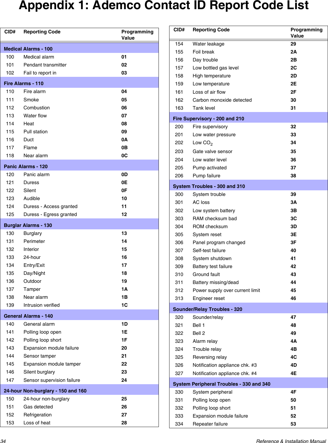
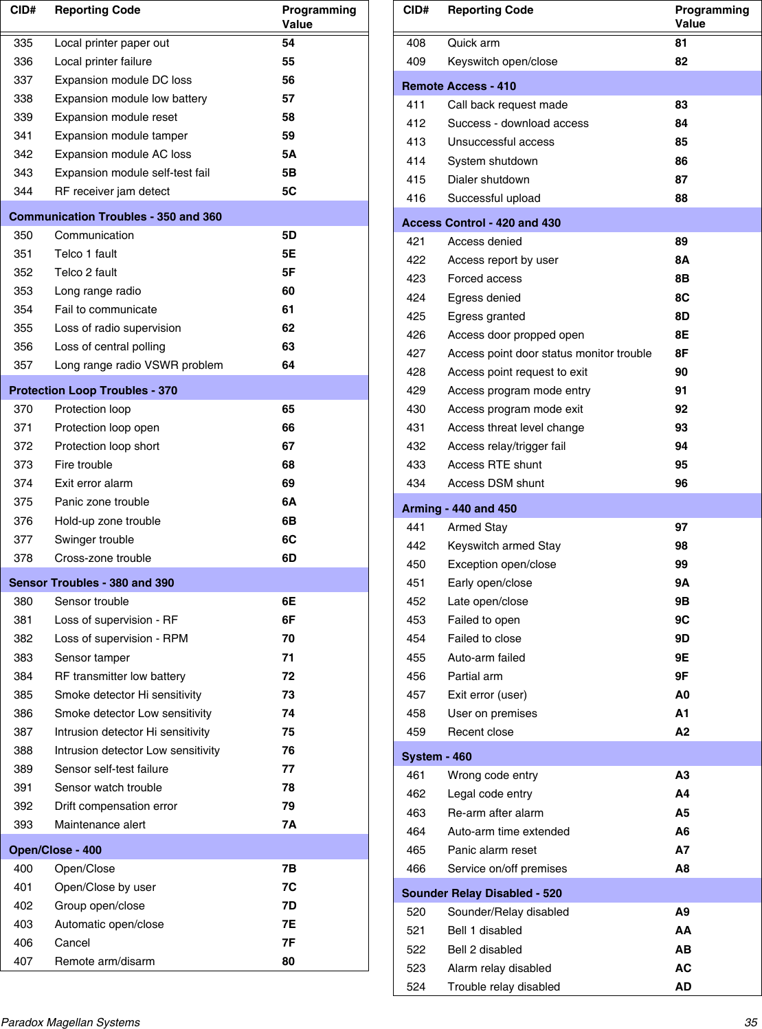
![24 Reference & Installation ManualReporting and Dialer SettingsReport CodesA report code is a 1- or 2-digit hexadecimal value consisting of digits from 1 to F. Each section from [120] to [156] represents a set of up to four specific events and each of these events can be programmed with a separate 1- or 2-digit report code.Only the Ademco Slow, Silent Knight, and Sescoa formats support 1-digit report codes. To program a 1-digit report code, press the [0] key followed by the desired hexadecimal digit or vice versa. When a specific event occurs, the console will attempt to transmit the programmed report code to the central station. The method of report code transmission is defined by the Reporting Formats (see page 27) and the Event Call Direction (see page 27). These two items define how and where the report codes are transmitted. If you are using the Ademco Contact ID format, sections [120] to [156] do not have to be programmed. For more information, refer to Reporting Formats (see page 27). The following sub-sections provide a brief description of the events that the Magellan console can report.Arming Report CodesSections [120] to [123]A report code can be programmed for each of the 16 User Codes. When using an access code to arm the system, the Magellan console can send the appropriate report code to the central station, identifying which user armed the system.Special Arming Report CodesSections [124] and [125]Whenever the system is armed using one of the special arming features listed below, the console can send the appropriate report code to the central station identifying how the system was armed.Section [124]• Timed Auto-arming: The system has armed itself at the programmed time (see page 20). • Late to Close: Reports every day at the time specified by the Auto-arm Timer (see page 20). • No Movement: The system has armed itself after the programmed period without movement (see No Movement Auto-Arming on page 20).• Partial Arming: The system was Stay, Instant or Force Armed or armed with Bypassed zones.Section [125]• One-touch Arming: The system was armed using a One-touch Arming feature (see page 21).• Remote Arming: The system was armed using the WinLoad software. • Future use• Future useDisarming Report CodesSections [126] to [129]A report code can be programmed for each of the 16 User Codes. Whenever an access code is used to disarm the system or an alarm, the Magellan console can send the appropriate report code to the central station, identifying which user disarmed the system. The Disarming and the Special Disarming report codes can be transmitted every time the system is disarmed or only when the system is disarmed after an alarm (see Disarming Reporting Options on page 29).Special Disarming Report CodesSection [130]Whenever using one of the special disarming features, the Magellan console can send the report code to the central station, identifying how the system was disarmed.• Cancel Auto-arm: The system is disarmed during the Timed Auto-arm's 60-second Exit Delay (see page 20). Only reports if Disarming Reporting Options (see page 29) are set to always report disarming. • Remote Disarm: System is disarmed using the WinLoad software.• Future use• Future useZone Alarm Report CodesSections [131] to [134]A report code can be programmed for each of the 16 available zones. Whenever a zone generates an alarm, the console can send the appropriate report code to the central station, identifying which zone generated an alarm.Zone Alarm Restore Report CodesSections [135] to [138]A report code can be programmed for each of the 16 available zones. The Magellan console can transmit these report codes to the central station identifying which zone was restored. A zone is restored when it closes after generating an alarm or once the bell has cut-off after alarm generation. Please refer to Zone Alarm Restore Report Codes on page 24. Special Alarm Report CodesSections [139] and [140]Whenever the system generates an alarm due to one of the conditions listed below, the control panel can send the appropriate report code to the central station identifying the type of alarm.Section [139]• Emergency Panic: Panic keys [1] and [3] (page 23) or the appropriate button(s) on a remote control (page 18) have been pressed.](https://usermanual.wiki/Paradox-Security-Systems/MG6060.Installation-guide-with-FCC-warnings/User-Guide-481305-Page-26.png)
![Paradox Magellan Systems 25• Auxiliary Panic: Panic keys [4] and [6] (page 23) or the appropriate button(s) on a remote control (page 18) have been pressed.• Fire Panic: Panic keys [7] and [9] (page 23) or the appropriate button(s) on a remote control (page 18) have been pressed.• Recent Closing: Reports when an alarm is generated after arming the system within period defined by the Recent Close Delay (see page 28).Section [140]• Auto-zone Shutdown: A zone communicates more than the programmed number of transmissions in a single armed period (see page 15). • Duress: A Duress access code is keyed in (see page 12). • Paramedical alarm• Future useZone Tamper Report CodesSection [141] to [144]A report code can be programmed for each of the 16 available zones. Whenever a tamper or wire fault occurs on a zone, the Magellan console can send the appropriate report code to the central station identifying which zone was tampered.If Tamper Recognition (see page 22) is disabled, the console will not report the occurrence of any tampers, wire faults or tamper restores.Zone Tamper Restore Report CodesSections [145] to [148]A report code can be programmed for each of the 16 available zones. Whenever a tampered zone is restored, the Magellan console can send the appropriate report code to the central station identifying which zone has been restored.If Tamper Recognition (see page 22) is disabled, the console will not report the occurrence of any tampers, wire faults or tamper restores.System Trouble Report CodesSection [149] to [151]Whenever the system generates one of the instances listed below, the console can send the appropriate report code to the central station identifying the type of system trouble.Section [149]• Console Tamper: A tamper has been detected on the console itself (see Console Tamper Supervision on page 31).• AC Failure: Magellan has detected a loss of AC power. Transmission of this report code can be delayed (see Power Failure Report Delay on page 29).• Battery Failure: The backup battery is disconnected or battery voltage is ≤ (less than or equal to)6.9V.• Timer Loss: The console has detected a loss in time or clock failure.Section [150]• Future use• Fail To Communicate: The Magellan console has failed all attempts to communicate with the central station. The report code will be transmitted upon the next successful attempt.• Wireless Low Battery: The battery voltage of an Omnia wireless transmitter (motion detector or contact switch) has dropped below recommended limits.• Tx Supervision Loss: Check-in Supervision (page 22) has been enabled and a transmitter is no longer communicating with the system.Section [151]• Future use• Future use• Future use• Future useSystem Trouble Restore CodesSections [152] to [154]Whenever the system restores one of the troubles listed in sections [149] and [150] (see System Trouble Report Codes on page 25), the Magellan console can send the appropriate report code to the central station identifying the type of system trouble restored. If Telephone Line Monitoring is enabled (see page 28), use the first two digits to program a TLM Restore report code that the console can transmit.Special Reporting CodesSections [155] and [156]Whenever the system generates one of the instances listed below, the Magellan console can send the appropriate report code to the central station identifying the type of system occurrence.Section [155]• Cold Start: The console was completely shutdown (no battery, no AC) and then was restarted.• Test Report: A test report has been generated automatically (see page 29).• Future use• WinLoad Logout: The console has ended communication with WinLoad.Section [156]• Installer logon: Installer has entered the programming mode.• Installer Logout: Installer has exited the programming mode.• Closing Delinquency: The last time the system was armed is greater than the programmed Closing Delinquency timer (page 21).• Future useConsole Telephone NumbersMagellan can dial up to two different central station telephone numbers and one Pager telephone number. You can enter any digit from 0 to 9 and any special keys or functions (see Table 8 on page 26) up to a maximum of 32 digits. If the number is less than 32 digits, press the left [ACTION] key (OK) to save the message.](https://usermanual.wiki/Paradox-Security-Systems/MG6060.Installation-guide-with-FCC-warnings/User-Guide-481305-Page-27.png)
![26 Reference & Installation ManualTable 8: Special Keys for Telephone NumbersCentral Station Telephone Numbers (CSTNs)Section [111] = Central Station Telephone Number 1Section [112] = Central Station Telephone Number 2The Magellan console uses the CSTNs (Central Station Telephone Numbers) programmed in sections [111] and/or [112] to connect and communicate with the central monitoring station. The following situations also apply:• If after eight attempts of calling one central station telephone number have failed, the console will then dial the backup telephone number (if section [099] option [1] is enabled. See CSTN 2 as Backup Number on page 26). • If the Alternate Dial option (page 28) is enabled, the console will dial the programmed backup telephone number after every failed attempt (if section [099] option [1] is enabled. See CSTN 2 as Backup Number on page 26). • If no backup telephone number is programmed, the console will never report to the backup telephone number. For more information on how these telephone numbers are used, please refer to Event Call Direction on page 27 and Reporting Formats on page 27. Also refer to Delay Between Dialing Attempts on page 28.CSTN 2 as Backup NumberSection [099]: Option [1]Option [1] OFF =Use CSTN 2 as a central station telephone number onlyOption [1] ON = CSTN 2 can be used a backup telephone number (default)CSTN 2 can also be used as a backup telephone number. If section [099] option [1] is enabled (ON) the console will use CSTN 2 as a backup telephone number.For more information, please refer to Central Station Telephone Numbers (CSTNs) on page 26 and Alternate Dial Option on page 28.Pager Telephone NumberSection [113]The Magellan console uses the Pager telephone number programmed in section [113] to connect and communicate the numeric pager message programmed in section [114] (see Pager Reporting Message on page 26) to a pager.Pager Reporting MessageSection [114]: 32-digit decimal number (0 to 9 as well as [*] and [#]) Program the desired numeric message you wish to send whenever the console dials the Pager telephone number in section [114]. If the message is less than 32 digits, press the left [ACTION] key (ok) to save the message.Voice Message Telephone NumbersThe Magellan console will use the Voice Message telephone numbers (which are programmed in the Installer menu. Refer to the Magellan Quick Setup Guide for more information) to play a pre-recorded message to an external telephone or cellular telephone. Please note the following when programming and using this feature:• The console will only dial a Voice Message telephone number when the system is in alarm. The console begins with the first programmed Voice Message telephone number.• When the call is connected, the console will play the pre-recorded message and the zone labels of all the zones that are in alarm.• The person at the other end of the telephone must acknowledge the call by pressing the [#] key on their telephone.• The console will repeat the message a programmed amount of times (see Voice Message Repetitions on page 26) if no acknowledgement is immediately received.• If no acknowledgement is received before the number of repetitions has elapsed, the console will then call the next programmed Voice Message telephone number and repeat the process.• After calling the last programmed Voice Message telephone number without an acknowledgement, the console will once again call the first Voice Message telephone number and repeat the process a maximum of three times.• If no acknowledgement is received after the third time, the console will generate a Fail to Comm. event and trouble.Voice Message RepetitionsSection [079]: 001 to 255 repetitions; Default = 3 repetitionsThis feature determines the amount of times the console will repeat the pre-recorded message played with the Voice Message telephone number without receiving an acknowledgement. Enter any 3-digit number from 001 to 255 into section [079] to program the Voice Message Repetitions feature.Service Telephone NumberSection [119]When there is a trouble in the system that requires servicing from your installer, the console will offer you the option of calling the telephone number programmed in section [119]. After selecting the option, the console becomes a speaker-phone.Refer to the Magellan User Guide for more information on using this feature.Console Account NumberSection [107]All report codes are preceded by a 4-digit or 3-digit Console Account Number to ensure correct identification of the Magellan console. The Console account number can be any hexa-digit from 1 to F. To enter a 3-digit account number, simply press the Keys to press Action or Value[*] *[#] #Center [ACTION] (pause) key Add a 4-second pause to the telephone number. Press the key and a “P” will be inserted into the telephone number](https://usermanual.wiki/Paradox-Security-Systems/MG6060.Installation-guide-with-FCC-warnings/User-Guide-481305-Page-28.png)
![Paradox Magellan Systems 27[0] key followed by the 3-digit account number. Also, when using 3-digit account numbers, you must use 1-digit report codes.Reporting FormatsSection [105] = Reporting Format for CSTN 1Section [106] = Reporting Format for CSTN 2The reporting formats apply only to the CSTNs (Central Station Telephone Numbers) programmed in sections [111] and [112] (page 26)The Magellan console can use a number of different reporting formats and each Central Station Telephone Number can be programmed with a different reporting format. The three digits entered into section [105] represents the reporting format used to communicate with Central Station Telephone Number 1 while the three digits entered into section [106] represents the reporting format used to communicate with Central Station Telephone Number 2.Table 9: Reporting FormatsUL Note: The installer is required to verify the complete compatibility of the DAC Receiver and formats at least once per year.Standard Pulse FormatsThe Magellan console can use the Ademco slow, Silent Knight and SESCOA standard pulse reporting formats (see Table 9 on page 27).Ademco Contact IDAdemco Contact ID is a fast communicator format that uses tone reporting instead of pulse reporting. This communicator format also uses a pre-defined list of industry standard messages and report codes that will suit most of your basic installation needs.• To manually program the report codes, use the 2-digit hexadecimal values from the Contact ID Report Codes List in the Magellan Programming Guide. • Enter 00 to disable reporting or FF to use the default report code from the Automatic Report Code List in the Programming Guide.Please refer to Appendix 1: Ademco Contact ID Report Code List on page 34 for a complete list of the format’s pre-defined industry standard messages and report codes.SIA FSKSIA FSK is a fast communicator format that uses tone reporting instead of pulse reporting. This communicator format uses a pre-defined list of industry standard messages and report codes that will suit most basic installation needs.Please refer to Appendix 1: Ademco Contact ID Report Code List on page 34 for a complete list of the format’s pre-defined industry standard messages and report codes.Event Call DirectionSection [100]: Options [1] to [3]; Arming/DisarmingOption [1] ON = Call CSTN 1Option [2] ON = Call CSTN 2Option [3] ON = Call Pager telephone numberSection [100]: Options [5] to [7]; Alarm/Alarm RestoreOption [5] ON = Call CSTN 1Option [6] ON = Call CSTN 2Option [7] ON = Call Pager telephone numberSection [101]: Options [1] to [3]; Tamper/Tamper RestoreOption [1] ON = Call CSTN 1Option [2] ON = Call CSTN 2Option [3] ON = Call Pager telephone numberSection [101]: Options [5] to [7]; Trouble/Trouble RestoreOption [5] ON = Call CSTN 1Option [6] ON = Call CSTN 2Option [7] ON = Call Pager telephone numberSection [102]: Options [1] to [3]; SpecialOption [1] ON = Call CSTN 1Option [2] ON = Call CSTN 2Option [3] ON = Call Pager telephone numberThe events are divided into five groups (see above) where each event group can be programmed to dial up to three telephone numbers (CSTN 1 & 2 and the Pager telephone number) with one as a possible backup (CSTN 2. See CSTN 2 as Backup Number on page 26).• When a reportable event occurs in the system, the Magellan console will begin dialing the numbers sequentially starting from CSTN 1 (if enabled), skipping any disabled numbers and stopping once all selected telephone numbers have been called.• If after eight attempts of trying to call the central monitoring station have failed, the console will then dial the selected backup telephone number (if enabled. See CSTN 2 as Backup Number on page 26). • If the Alternate Dial option (see page 28) is enabled, the console will dial the programmed backup telephone number (if enabled. See CSTN 2 as Backup Number on page 26) after every failed attempt. • If no backup telephone number is programmed or section [099] option [1] is disabled (OFF. See page 28), the console will never report to the backup telephone number. For more information, please refer to Central Station Telephone Numbers (CSTNs) on page 26, Alternate Dial Option on page 28, CSTN 2 as Backup Number on page 26 and Delay Between Dialing Attempts on page 28.Example: The system is armed and zone 1 has been breached causing an alarm. If options [5] and [7] are OFF and option [6] is ON in section [100], the console will attempt to communicate with CSTN 2 in order to transmit the Zone 1 Alarm Report Code programmed in section [131].3-digit Value Reporting Format001 Ademco slow (1400Hz, 1900Hz, 10BPS)002 Silent Knight Fast (1400Hz, 1900Hz, 10BPS)003 SESCOA (2300Hz, 1800Hz, 20BPS)004 Ademco Contact ID005 SIA FSK](https://usermanual.wiki/Paradox-Security-Systems/MG6060.Installation-guide-with-FCC-warnings/User-Guide-481305-Page-29.png)
![28 Reference & Installation ManualDelay Between Dialing AttemptsSection [076]: 001 to 255 seconds; 000 = disabled; Default = 20 secondsThis delay determines the amount of time the Magellan console will wait between each dialing attempt. Alternate Dial OptionSection [098]: Option [5]Option [5] OFF = Alternate Dial Disabled (default)Option [5] ON = Alternate Dial EnabledWith option [5] OFF, the Magellan console will dial the programmed backup telephone number CSTN 2 (See CSTN 2 as Backup Number on page 26) only after all attempts to call one CSTN have failed. With option [5] ON, the console will dial the backup telephone number after every failed attempt.Force Dial OptionSection [098]: Option [6]Option [6] OFF = Force Dial Disabled (default)Option [6] ON = Force Dial EnabledWhen option [6] is enabled, the Magellan console will dial a telephone number even if no dial tone is present after 3 seconds. Dialing MethodSection [098]: Option [7]Option [7] OFF = Pulse Dialing Option [7] ON = Tone / DTMF Dialing (default)When option [4] is ON, the Magellan console is set for Tone/DTMF dialing. When option [4] is OFF, the console is set for pulse dialing. Refer to Pulse Ratio on page 28 for information on setting the pulse ratio.Pulse RatioSection [098]: Option [8]Option [8] OFF = European Pulse Ratio of 1:2 Option [8] ON = U.S.A. Pulse Ratio of 1:1.5 (default)When using Pulse dialing, you can select one of two Pulse Ratios. Although most European countries use the 1:2 pulse ratio, the 1:1.5 ratio may provide better results in some cases. The same applies for North American countries. If the 1:1.5 pulse ratio is not providing the desired results, the 1:2 ratio may be used.Switch to Pulse Dialing on 5th AttemptSection [098]: Option [3]Option [3] OFF = Switch to pulse dialing on fifth attempt disabled (default)Option [3] ON = Switch to pulse dialing on fifth attempt enabledWhen section [098] option [3] is ON, the Magellan console switches from tone/DTMF dialing to pulse dialing on the fifth attempt to report events to the Central Monitoring Station. The console continues to use pulse dialing until it establishes communication. When the console switches to another CSTN, it returns to tone/DTMF dialing and will once again switch to pulse dialing on the fifth attempt.Telephone Line Monitoring (TLM)Section [098]: Options [1] and [2]When enabled, the system verifies the existence of a telephone line once every second. A line test failure occurs when the TLM detects less than 3 volts for the period defined by the TLM Fail Timer (page 28). If the line test fails, the Magellan console generates one or more conditions as defined by the TLM settings below. These will be restored when the console detects the telephone line again. Table 10: Telephone Line Monitoring OptionsPlease note that when the dialer detects an incoming call, the TLM test will stop for 1 minute.TLM Fail TimerSection [073]: 001 to 255 seconds; 000 = Disabled; Default = 32 secondsIf TLM does not detect the existence of a telephone line for the duration of this period, the control panel will generate the condition(s) defined by the TLM options (see Telephone Line Monitoring (TLM) on page 28).Recent Close DelaySection [066]: 001 to 255 seconds; 000 = Disabled; Default = DisabledIf after having armed the system, an alarm is generated within the period defined by the Recent Close Delay, the Magellan console will attempt to transmit the Recent Close report code programmed in section [139] (page 24). Options Description[1] [2]OFF OFF TLM disabled (default)OFF ON Trouble only: Upon a line test failure, a TLM trouble will appear in the console’s Trouble DisplayON OFF Alarm if System Armed: Upon a line test failure, a TLM trouble will appear in the console’s Trouble Display and if the system is armed, the console will generate an alarm.ON ON Silent Alarm becomes Audible: Upon a line test failure, a TLM trouble will appear in the console’s Trouble Display and causes a silent zone or silent panic alarm to switch to audible.](https://usermanual.wiki/Paradox-Security-Systems/MG6060.Installation-guide-with-FCC-warnings/User-Guide-481305-Page-30.png)
![Paradox Magellan Systems 29Auto-Test ReportSection [071]: 001 to 255 days; 000 = Disabled; Default = Disabled Section [084]: Time (HH:MM)The Magellan console will transmit the Test Report report code programmed into section [153] after the number of days programmed into section [071] has elapsed at the time programmed into section [084]. Use the 24-hour clock to program the time (i.e. 6:30PM = 18:30). The first Test Report will be transmitted within 24 hours after the feature is enabled at the time programmed in [084]. Example: Section [071] = 005 and section [084] = 13:00. The first Test Report will be sent at 1 PM that day and then the report will be sent every 5 days at 1 PM.Power Failure Report DelaySection [070]: 001 to 255 minutes; 000 = Disabled; Default = 15 minutesThe Magellan console will transmit the AC Failure report code programmed in section [149] after the Power Failure Report Delay period has elapsed. Disarm Reporting Options Section [093]: Option [5]Option [5] OFF = Always Report DisarmingOption [5] ON = Report Disarming only after Alarm (Default)With option [5] OFF, the Magellan console will send the Disarming report codes (see page 24) to the central monitoring station every time the system is disarmed. With option [5] ON, the console will send the Disarming report codes to the central monitoring station when the system is disarmed following an alarm.Zone Restore Report OptionsSection [094]: Option [2]Option [2] OFF = Report On Bell Cut-Off (Default)Option [2] ON = Report On Zone ClosureWith option [2] OFF, the Magellan console will send the Zone Alarm Restore report codes (see page 24) to the central monitoring station when the zone has returned to normal and the Bell Cut-Off Timer (see page 22) has elapsed. With option [2] ON, the console will send the Zone Alarm Restore report codes to the central station as soon as the zone returns to normal or when the system is disarmed.](https://usermanual.wiki/Paradox-Security-Systems/MG6060.Installation-guide-with-FCC-warnings/User-Guide-481305-Page-31.png)
![30 Reference & Installation ManualProgrammable OutputsA PGM is a programmable output that toggles to its opposite state (i.e. a normally open PGM will close) when a specific event has occurred in the system. For example, a PGM can be used to activate bells or strobe lights, open/close garage doors and much more. When a PGM closes, the control panel supplies a ground to the PGM activating any device or relay connected to it. When a PGM opens, the circuit opens from ground, therefore, cutting power to any devices connected to it. PGM Activation EventSection [086] = PGM1 Activation EventSection [088] = PGM2 Activation EventThis feature allows you to program the Magellan console to activate a PGM when a specific event occurs in the system. The PGM will remain in its active state until the programmed PGM Deactivation Event (see page 30) occurs or when the PGM Delay (see page 30) elapses. To program a PGM Activation Event:1. Enter the section that corresponds to the desired PGM; PGM1 = [086], PGM2 = [088].2. Enter the [EVENT GROUP #]. 3. Enter the [SUB-GROUP #]. The “AC Loss” PGM event (Event Group #28, Event Sub-group #01) will only occur after the Power Failure Report Delay elapses (see page 29).For the Event List, see the PGM Table in the Magellan Programming Guide.PGM Deactivation EventSection [087] = PGM1Section [089] = PGM2After PGM activation (see PGM Activation Event on page 30), the PGM will return to its normal state (deactivate) when the programmed PGM Deactivation Event occurs. To program a Deactivation Event:1. Enter section that represents the desired PGM; PGM1 = [087], PGM2 = [089].2. Enter the [EVENT GROUP #]. 3. Enter the [SUB-GROUP #].A PGM can also be set to deactivate after a programmed period elapses (see PGM Delay on page 30). If using the PGM Delay, sections [087] and [089] can be used as a second PGM Activation Event.For the Event List, see the PGM Table in the Magellan Programming Guide.PGM Delay Section [068] = PGM1, Section [069] = PGM2001 to 255 seconds; 000 = Follow Deactivation Event; Default = 5 secondsInstead of deactivating the PGM on the occurrence of a specific event, the PGM will deactivate after the period programmed in here has elapsed. Enter 000 to have the PGMs deactivate with a PGM Deactivation Event (see page 30).If a PGM Delay is programmed, the PGM Deactivation Event can be used as a second PGM Activation Event.PGM Normal StateSection [090]: Options [7] (PGM1) and [8] (PGM2)Option [7] OFF = PGM1 Normally Open (default)Option [7] ON = PGM1 Normally ClosedOption [8] OFF = PGM2 Normally Open (default)Option [8] ON = PGM2 Normally ClosedA PGM toggles to its opposite state (i.e. a normally open PGM will close) when a specific event has occurred in the system. You can program each PGM output to be normally open (N.O.) or normally closed (N.C.) by enabling or disabling options [7] and [8] in section [090].PGM X10 OptionSection [091]: Options [7] (PGM1) and [8] (PGM2)Option [7] OFF = PGM1 used as programmable output (default)Option [7] ON = PGM1 used as X10 output 7Option [8] OFF = PGM2 used as programmable output (default)Option [8] ON = PGM2 used as X10 output 8With section [091] options [7] and [8] enabled (ON), PGMs 1 and 2 will follow the ON/OFF state of X10 outputs 7 and 8. Therefore the PGMs will function as follows:• When X10 output 7 is enabled, PGM1 will activate. When X10 output 7 is disabled, PGM1 will deactivate.• When X10 output 8 is enabled, PGM2 will activate. When X10 output 8 is disabled, PGM2 will deactivate.When section [091] options [7] and [8] are enabled, the PGM outputs will disregard their PGM activation and deactivation events (sections [086] to [089]).](https://usermanual.wiki/Paradox-Security-Systems/MG6060.Installation-guide-with-FCC-warnings/User-Guide-481305-Page-32.png)
![Paradox Magellan Systems 31System SettingsSoftware ResetSection [201]Performing a software reset will reset all programmed sections back to the factory defaults. To perform a software reset:1. Access the installer programming mode (page 11).2. Enter section [201].You can also perform a software reset by removing power to the console, pressing and holding down the [*] and [#] keys and then reapplying power to the console.Installer LockSection [180]: 000 = Disabled; 147 = Lock Enabled; Default = DisabledProgram 147 into section [180] to lock all programming. Performing a hardware reset will not affect the current console settings. To remove the Installer Lock, enter 000.Console Tamper SupervisionSection [090]: Option [5]Option [5] OFF = Console Tamper Supervision disabled (default)Option [5] ON = Console Tamper Supervision enabledMagellan can be programmed to monitor its on-board tamper status. The console will follow its programmed tamper recognition options. Refer to Tamper Recognition Options on page 22 for more information.Console Audible Trouble WarningSection [090]: Option [2]Option [2] OFF = Console beep on trouble disabled (default)Option [2] ON = Console beep on trouble enabledWhen enabled, the console emits an intermittent beep tone whenever a trouble condition occurs in the system. The intermittent beep tone remains activated until the user enters the Trouble Display by pressing the left [ACTION] key (I). The intermittent beeps will re-initialize whenever a new trouble occurs or the trouble restores and re-occurs.The only trouble not covered by this feature is the AC Power Failure trouble. See AC Power Failure Warning on page 31.FM Tuner OptionSection [093]: Option [8]Option [8] OFF = FM tuner is disabled when the system is armed (default)Option [8] ON = FM tuner is enabled when system is armedWith section [093] option [8] ON, the Magellan’s radio is turned ON automatically after the system is armed (after the Exit Delay timer has elapsed).Daylight Savings TimeSection [096]: Option [5]Option [5] OFF = Daylight savings time disabled (default)Option [5] ON = Daylight savings time enabledWith section [096] option [5] ON, Magellan adjusts the system’s clock (time) for daylight saving changes. At 2:00AM on the first Sunday of a full weekend in April, the console will add one hour to the programmed time (clock). At 2:00 AM on the last Sunday of a full weekend in October, the console will subtract one hour from the programmed time.AC Power Failure WarningSection [096]: Option [6]Option [6] OFF = AC power failure warning disabled (default)Option [6] ON = AC power failure warning enabledWith this feature enabled, the console emits an intermittent beep tone whenever an AC power failure is detected. The intermittent beep tone remains activated until the user enters the Trouble Display by pressing the left [ACTION] key (i). The intermittent beeps will re-initialize whenever the trouble occurs or the trouble restores and re-occurs.The Trouble DisplayWhen the system experiences problems or is tampered with, the Information symbol ( ) will appear on the LCD screen and the light will illuminate. The potential troubles that the Magellan system can experience are listed below. To access the Trouble Display:1. Press the key.2. Use the [NEXT] key to scroll through the displayed troubles.3. Press the [OK] key to view details on the desired trouble.Trouble DescriptionBypass There is a zone (or zones) that is bypassed in the system.Alarm Memory An alarm has occurred in the system. The zones displayed went into alarm.Console Low Bat The backup battery pack is disconnected, needs to be recharged or replaced.Doorbell Low Bat Wireless transmitter being used as a doorbell (page 17) requires its batteries changed.Zone Low Battery Zone(s) displayed indicate where a wireless transmitter’s battery needs to be replaced.Clock Loss The time and date were reset to default. To reprogram:1. Press the [MENU] key.2. Press the [3] key.3. Press the [12HRS] key to display the time using the 12-hour clock or the [24HRS] key to display the time using the 24-hour clock.4. Enter the desired time and then press [OK].5. Enter the date and then press [OK].](https://usermanual.wiki/Paradox-Security-Systems/MG6060.Installation-guide-with-FCC-warnings/User-Guide-481305-Page-33.png)
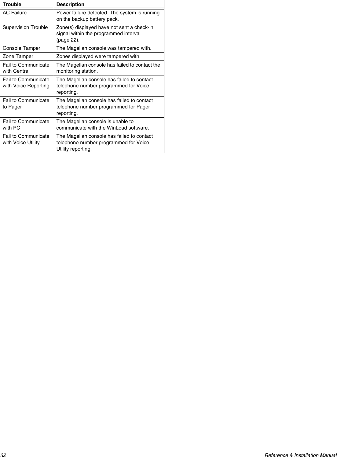
![Paradox Magellan Systems 33WinLoad Software SettingsPanel Answer OptionsThe following two options define how Magellan answers an incoming call from a computer using the WinLoad Installer Upload/Download Software.Answering Machine OverrideSection [074]: 010 to 255 seconds; 000 = disabled; Default = disabledWhen using WinLoad to communicate remotely with an installation site that uses an answering machine or service, the answering machine override must be programmed. Using WinLoad, you will call Magellan, hang up, then call back. If the installation site is called back within the delay programmed in section [074], the console will override the answering machine or service by picking-up the line after the first ring on the second call. You must wait at least 10 seconds before attempting the second call, otherwise, the console will think it is the same call. For details on how to use WinLoad, refer to the WinLoad On-line Help.Example: A security installation is using an answering machine set to answer after three rings. If section [074] has been programmed with 040 (40 seconds) and the second call is made within 40 seconds, Magellan will pick up the line on the first ring. If it takes more than 40 seconds, the console will not answer on the first ring and the answering machine will answer after three rings.Number of RingsSection [072]: 001 to 015 rings; 000 = disabled; Default = 008This value represents the number of rings Magellan will wait before picking-up the line. If the line is not answered after the number of programmed rings, the console will answer the call. You must wait at least 10 seconds before attempting the second call or Magellan will think it is the same call.Panel IdentifierSection [108]: 4-digit Hexa-decimal number from 0000 to FFFFThis 4-digit code identifies the console to WinLoad before initiating communication. Magellan will verify that the Panel Identifier in the WinLoad software is the same as the code programmed in section [108]. If the codes do not match, the console will not establish communication. Therefore, be sure to program the same panel identifier code into both Magellan and WinLoad.PC PasswordSection [109]: 4-digit Hexa-decimal number from 0000 to FFFFThis 4-digit password identifies the PC to Magellan before establishing communication. Program the same PC password into both the console and WinLoad. If the passwords do not match, WinLoad will not establish communication.PC Telephone NumberSection [118]Magellan will dial the number programmed in section [118] when trying to initiate communication with a computer using WinLoad. You can enter any digit from 0 to 9 and any special keys or functions (see Table 8 on page 26) up to a maximum of 32 digits.Call Back FeatureSection [098]: Option [4]Option [4] OFF = Call Back feature disabled (default)Option [4] ON = Call Back feature enabledThe Call Back feature provides additional security. When section [098] option [4] in ON and a computer using WinLoad attempts to communicate with Magellan, the console hangs up and calls the computer back to re-verify identification codes and re-establish communication. When Magellan hangs up, WinLoad automatically goes into Wait for Call Mode, ready to answer when the console calls back. The PC Telephone number must be programmed (see PC Telephone Number on page 33).](https://usermanual.wiki/Paradox-Security-Systems/MG6060.Installation-guide-with-FCC-warnings/User-Guide-481305-Page-35.png)