Paradox Security Systems OMNPMD75 Motion Detector User Manual OMN PMD75 EI00

Paradox Security Systems Motion Detector OMN PMD75 EI00

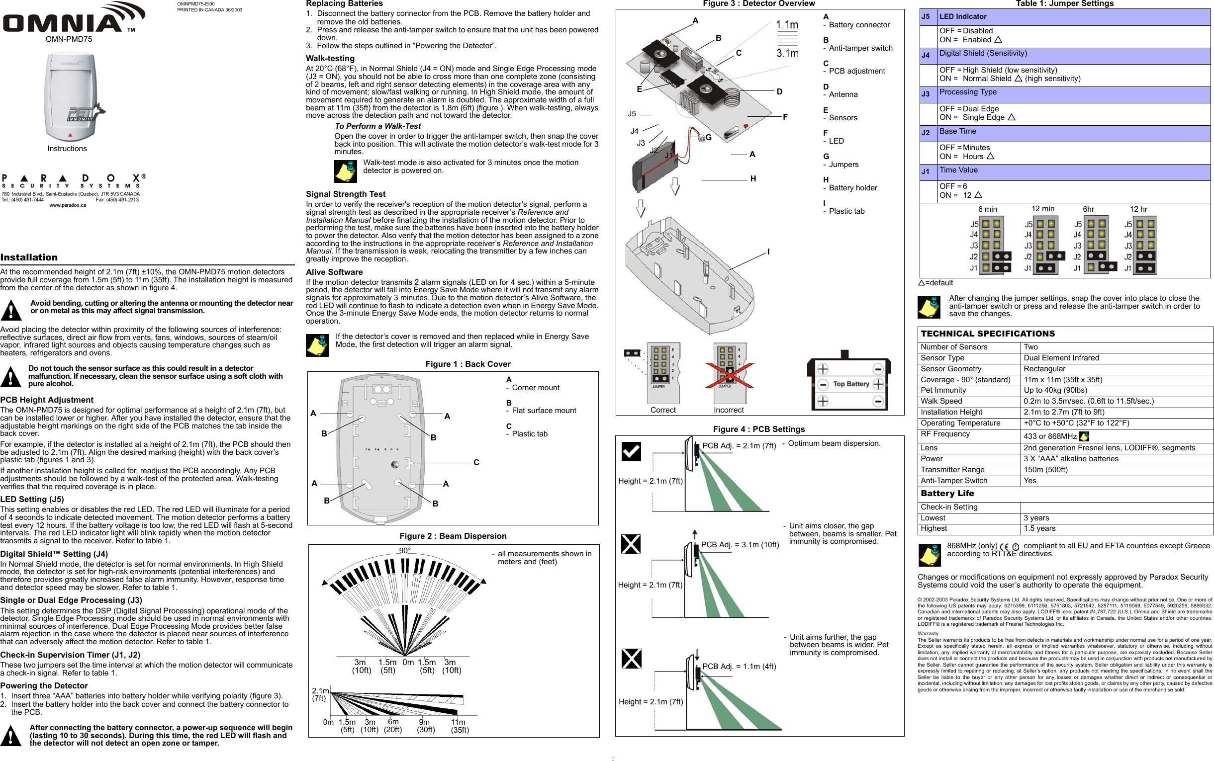
Installation Instructions

OMNPMD75-EI00PRINTED IN CANADA 06/2003InstallationAt the recommended height of 2.1m (7ft) ±10%, the OMN-PMD75 motion detectors provide full coverage from 1.5m (5ft) to 11m (35ft). The installation height is measured from the center of the detector as shown in figure 4.Avoid bending, cutting or altering the antenna or mounting the detector near or on metal as this may affect signal transmission.Avoid placing the detector within proximity of the following sources of interference: reflective surfaces, direct air flow from vents, fans, windows, sources of steam/oil vapor, infrared light sources and objects causing temperature changes such as heaters, refrigerators and ovens.Do not touch the sensor surface as this could result in a detector malfunction. If necessary, clean the sensor surface using a soft cloth with pure alcohol.PCB Height AdjustmentThe OMN-PMD75 is designed for optimal performance at a height of 2.1m (7ft), but can be installed lower or higher. After you have installed the detector, ensure that the adjustable height markings on the right side of the PCB matches the tab inside the back cover. For example, if the detector is installed at a height of 2.1m (7ft), the PCB should then be adjusted to 2.1m (7ft). Align the desired marking (height) with the back cover’s plastic tab (figures 1 and 3). If another installation height is called for, readjust the PCB accordingly. Any PCB adjustments should be followed by a walk-test of the protected area. Walk-testing verifies that the required coverage is in place. LED Setting (J5)This setting enables or disables the red LED. The red LED will illuminate for a period of 4 seconds to indicate detected movement. The motion detector performs a battery test every 12 hours. If the battery voltage is too low, the red LED will flash at 5-second intervals. The red LED indicator light will blink rapidly when the motion detector transmits a signal to the receiver. Refer to table 1.Digital Shield™ Setting (J4)In Normal Shield mode, the detector is set for normal environments. In High Shield mode, the detector is set for high-risk environments (potential interferences) and therefore provides greatly increased false alarm immunity. However, response time and detector speed may be slower. Refer to table 1.Single or Dual Edge Processing (J3)This setting determines the DSP (Digital Signal Processing) operational mode of the detector. Single Edge Processing mode should be used in normal environments with minimal sources of interference. Dual Edge Processing Mode provides better false alarm rejection in the case where the detector is placed near sources of interference that can adversely affect the motion detector. Refer to table 1.Check-in Supervision Timer (J1, J2)These two jumpers set the time interval at which the motion detector will communicate a check-in signal. Refer to table 1.Powering the Detector1. Insert three “AAA” batteries into battery holder while verifying polarity (figure 3).2. Insert the battery holder into the back cover and connect the battery connector to the PCB. After connecting the battery connector, a power-up sequence will begin (lasting 10 to 30 seconds). During this time, the red LED will flash and the detector will not detect an open zone or tamper.Replacing Batteries1. Disconnect the battery connector from the PCB. Remove the battery holder and remove the old batteries.2. Press and release the anti-tamper switch to ensure that the unit has been powered down.3. Follow the steps outlined in “Powering the Detector”.Walk-testingAt 20°C (68°F), in Normal Shield (J4 = ON) mode and Single Edge Processing mode (J3 = ON), you should not be able to cross more than one complete zone (consisting of 2 beams, left and right sensor detecting elements) in the coverage area with any kind of movement; slow/fast walking or running. In High Shield mode, the amount of movement required to generate an alarm is doubled. The approximate width of a full beam at 11m (35ft) from the detector is 1.8m (6ft) (figure ). When walk-testing, always move across the detection path and not toward the detector.To Perform a Walk-TestOpen the cover in order to trigger the anti-tamper switch, then snap the cover back into position. This will activate the motion detector’s walk-test mode for 3 minutes.Walk-test mode is also activated for 3 minutes once the motion detector is powered on.Signal Strength TestIn order to verify the receiver's reception of the motion detector’s signal, perform a signal strength test as described in the appropriate receiver’s Reference and Installation Manual before finalizing the installation of the motion detector. Prior to performing the test, make sure the batteries have been inserted into the battery holder to power the detector. Also verify that the motion detector has been assigned to a zone according to the instructions in the appropriate receiver’s Reference and Installation Manual. If the transmission is weak, relocating the transmitter by a few inches can greatly improve the reception.Alive SoftwareIf the motion detector transmits 2 alarm signals (LED on for 4 sec.) within a 5-minute period, the detector will fall into Energy Save Mode where it will not transmit any alarm signals for approximately 3 minutes. Due to the motion detector’s Alive Software, the red LED will continue to flash to indicate a detection even when in Energy Save Mode. Once the 3-minute Energy Save Mode ends, the motion detector returns to normal operation.If the detector’s cover is removed and then replaced while in Energy Save Mode, the first detection will trigger an alarm signal.Figure 1 : Back CoverFigure 2 : Beam DispersionFigure 3 : Detector OverviewFigure 4 : PCB Settings:Table 1: Jumper SettingsU=defaultAfter changing the jumper settings, snap the cover into place to close the anti-tamper switch or press and release the anti-tamper switch in order to save the changes.868MHz (only)  compliant to all EU and EFTA countries except Greece according to RTT&E directives.Changes or modifications on equipment not expressly approved by Paradox Security Systems could void the user’s authority to operate the equipment.© 2002-2003 Paradox Security Systems Ltd. All rights reserved. Specifications may change without prior notice. One or more ofthe following US patents may apply: 6215399, 6111256, 5751803, 5721542, 5287111, 5119069, 5077549, 5920259, 5886632.Canadian and international patents may also apply. LODIFF® lens: patent #4,787,722 (U.S.). Omnia and Shield are trademarksor registered trademarks of Paradox Security Systems Ltd. or its affiliates in Canada, the United States and/or other countries.LODIFF® is a registered trademark of Fresnel Technologies Inc. WarrantyThe Seller warrants its products to be free from defects in materials and workmanship under normal use for a period of one year.Except as specifically stated herein, all express or implied warranties whatsoever, statutory or otherwise, including withoutlimitation, any implied warranty of merchantability and fitness for a particular purpose, are expressly excluded. Because Sellerdoes not install or connect the products and because the products may be used in conjunction with products not manufactured bythe Seller. Seller cannot guarantee the performance of the security system. Seller obligation and liability under this warranty isexpressly limited to repairing or replacing, at Seller’s option, any products not meeting the specifications. In no event shall theSeller be liable to the buyer or any other person for any losses or damages whether direct or indirect or consequential orincidental, including without limitation, any damages for lost profits stolen goods, or claims by any other party, caused by defectivegoods or otherwise arising from the improper, incorrect or otherwise faulty installation or use of the merchandise sold.  InstructionsOMN-PMD75A-Corner mountB- Flat surface mountC-Plastic tabAAAABBBBC- all measurements shown in meters and (feet)90°  3m (10ft)  3m (10ft)1.5m (5ft)1.5m (5ft)0m0m2.1m(7ft)1.5m (5ft)  3m(10ft)  6m(20ft)  9m (30ft) 11m (35ft)ABCDFJ5J4J3J2 J1EA- Battery connectorB- Anti-tamper switchC- PCB adjustmentD- AntennaE-SensorsF-LEDG- JumpersH- Battery holderI-Plastic tabCorrect IncorrectGAHI- Optimum beam dispersion.- Unit aims further, the gap between beams is wider. Pet immunity is compromised.- Unit aims closer, the gapbetween, beams is smaller. Pet immunity is compromised.Height = 2.1m (7ft)PCB Adj. = 2.1m (7ft)PCB Adj. = 1.1m (4ft)PCB Adj. = 3.1m (10ft)Height = 2.1m (7ft)Height = 2.1m (7ft)J5 LED IndicatorOFF = DisabledON =  Enabled UJ4 Digital Shield (Sensitivity) OFF = High Shield (low sensitivity)ON =  Normal Shield U (high sensitivity)J3 Processing TypeOFF = Dual EdgeON =  Single Edge UJ2 Base TimeOFF = MinutesON =  Hours UJ1 Time ValueOFF = 6ON =  12 UTECHNICAL SPECIFICATIONSNumber of Sensors TwoSensor Type Dual Element InfraredSensor Geometry RectangularCoverage - 90° (standard) 11m x 11m (35ft x 35ft)Pet Immunity Up to 40kg (90lbs)Walk Speed 0.2m to 3.5m/sec. (0.6ft to 11.5ft/sec.)Installation Height 2.1m to 2.7m (7ft to 9ft)Operating Temperature +0°C to +50°C (32°F to 122°F)RF Frequency 433 or 868MHz Lens 2nd generation Fresnel lens, LODIFF®, segmentsPower 3 X “AAA” alkaline batteriesTransmitter Range 150m (500ft) Anti-Tamper Switch YesBattery LifeCheck-in SettingLowest 3 yearsHighest 1.5 years6 min  12 min  6hr 12 hr

Navigation menu