Paradox Security Systems OMNRCV3 OMN-RCV3 RECEIVER User Manual OMNRCV3S EI00
Paradox Security Systems OMN-RCV3 RECEIVER OMNRCV3S EI00
UserManual.wiki
>
Paradox Security Systems
>
OMNRCV3 User Manual
Installation manual
Navigation menu
Upload a User Manual
Namespaces
Wiki Guide
HTML
PDF
Info
Views
User Manual
Discussion / Help
Navigation
![6 Reference & Installation ManualTo successfully install an Omnia wireless system to your Spectra system, ensurethat the following steps are completed:1. Install the Omnia Receiver. Connect the Omnia Receiver to the Spectra controlpanel and power up.2. Assign the remote controls if necessary.3. Assign the transmitters (door contacts and motion detectors), and program theirzones.4. Install the transmitters. Insert the batteries, and close the transmitter cover.5. Wait for the control panel to be in “ready” mode. The status light on the keypadwill be green when the control panel is ready.6. In order to ensure proper synchronization between the transmitters and receiver,open and close the transmitters’ covers and zones.3.1 HOW TO ENTER PROGRAMMING MODEProgramming of the OMN-RCV3 is done in Programming Mode through any keypadconnected to the Spectra control panel.The OMN-RCV3’s programming guide can be found in the appropriateSpectra Programming Guide.3.2 WIRELESS TRANSMITTER PROGRAMMINGThe programming of the wireless transmitters (detectors and door contacts) isaccomplished in two steps:1. Assigning the detectors and door contacts to the Wireless Receiver Module.2. Programming the zones in the Spectra control panel.How to enter programming mode.1. Press the [ENTER] button.2. Enter your [INSTALLER CODE] (default = 000000).3. Enter the [SECTION NUMBER] you wish to program.4. Enter the required [DATA].](https://usermanual.wiki/Paradox-Security-Systems/OMNRCV3/User-Guide-168871-Page-6.png)
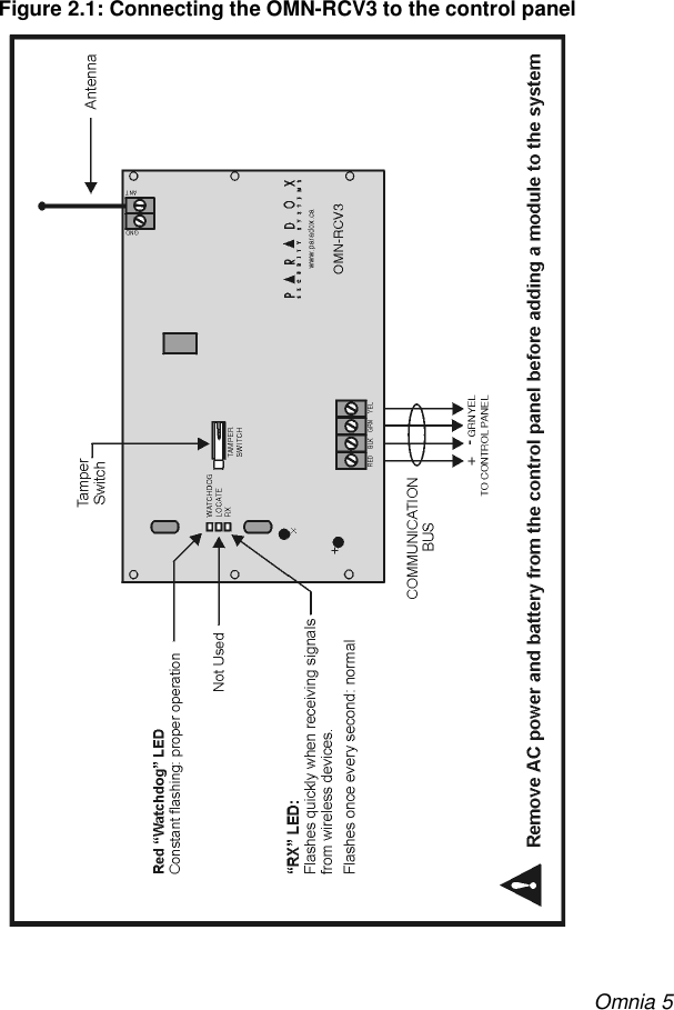
![Omnia 73.2.1 ASSIGNING DETECTORS AND DOOR CONTACTS TO THE RECEIVERSECTIONS [601] TO [608]In Spectra systems, up to 8 wireless transmitters (detectors and doorcontacts) can be assigned to each Receiver Module. Section [601] to [608]represent expansion inputs 1 to 8 respectively. For example, section [601] isassigned to expansion input 1, section [602] is assigned to expansion input 2,etc. (refer to Table 3.1). Each Expansion Input represents a specific zone inthe system depending on the type of Spectra control panel being used andwhether the ATZ option is enabled (refer to the appropriate Spectra controlpanel Programming Guide).Table 3.1: Sections and Expansion InputsDo not assign detection devices from different modules to the sameexpansion input. For example, do not assign a wireless transmitterto section [601], then connect a detection device to input Z1 of theAPR3-ZX8. Section # 6-digit Serial Number Expansion Input[601] ___/___/___/___/___/___ Input 1[602] ___/___/___/___/___/___ Input 2[603] ___/___/___/___/___/___ Input 3[604] ___/___/___/___/___/___ Input 4[605] ___/___/___/___/___/___ Input 5[606] ___/___/___/___/___/___ Input 6[607] ___/___/___/___/___/___ Input 7[608] ___/___/___/___/___/___ Input 8How to assign detectors & door contacts to the receiver module.In step 3 in section 3.1 on page 6:1. Enter the desired [SECTION NUMBER] (601 to 608). 2. Enter the 6-digit serial number of the detector or door contact.](https://usermanual.wiki/Paradox-Security-Systems/OMNRCV3/User-Guide-168871-Page-7.png)
![8 Reference & Installation ManualThe serial number is located on the inside of the transmitter or youcan use the Unknown Serial Number Display method (refer tosection 3.4 on page 10) to determine its serial number.The transmitters must be activated once having been assigned tothe Receiver. To activate a transmitter, insert the batteries and closethe cover. To ensure proper synchronization between the receiverand the transmitter, open and close the zone corresponding to thetransmitter.3.2.2 DELETING THE DETECTORS AND DOOR CONTACTSSECTIONS [601] TO [608]3.2.3 PROGRAMMING THE ZONES IN THE SPECTRA CONTROL PANELThe zones allocated to the wireless transmitters must be programmed in theSpectra control panel. Refer to the appropriate Spectra Reference &Installation Manual for instructions on programming the zones.3.3 VIEWING THE TRANSMITTER SIGNAL STRENGTHSECTIONS [631] TO [638]Once the detectors and/or door contacts have been installed and assigned to theReceiver Module, the signal strength of each transmitter can be verified in sections[631] to [638]. Each section represents the signal strength viewer for a specificdevice. For example, section [631] is the viewer for the device in section [601] andsection [638] is the viewer for the device in section [608]. Please note that thisfeature will only work with wireless transmitters that have already been assigned toan Expansion Input (zone) as described in section 3.2.1 on page 7. A reading of 1 isthe weakest and a reading of 8 is the strongest. An average reading of 3 and up isHow to delete the assigned transmitters.In step 3 in section 3.1 on page 6:1. Enter the desired [SECTION NUMBER] (601 to 608).2. Press the [FORCE] button six times to clear the serial number.](https://usermanual.wiki/Paradox-Security-Systems/OMNRCV3/User-Guide-168871-Page-8.png)
![Omnia 9acceptable. Sometimes moving the transmitter or receiver by a small amount willgreatly increase the signal reception.After entering the desired section, ignore the first reading as it will not beaccurate.You can also use the OMN-RCV3’s beep sequence feature to verify a transmitter’ssignal strength. When you press a transmitter’s tamper switch, beep tonesemanating from all the keypads connected to the communication bus will advise youof the transmitter’s signal strength.How to view a transmitter’s signal strength.In step 3 in section 3.1 on page 6:1. Enter the desired [SECTION NUMBER] (631 to 638).2. Press the transmitter’s tamper switch, or open the corresponding zone.On an LED keypad: The keypad will illuminate numbers 1 to 8.On an LCD keypad: The keypad will display from 1 to 8 characters on thescreen. For example, in the figure below the LCD screen shows a signalstrength reading of 5.How to attain a transmitter’s signal strength using the beep sequence.1. Press the transmitter’s tamper switch.2. Listen for the beep tones:If the signal strength is less than 3 = One beepIf the signal strength is between 3 and 6 = Two beepsIf the signal strength is greater than 6 = Three beeps](https://usermanual.wiki/Paradox-Security-Systems/OMNRCV3/User-Guide-168871-Page-9.png)
![10 Reference & Installation Manual3.4 VIEWING UNKNOWN SERIAL NUMBERSSECTION [630]This feature will display the serial number of any Omnia motion detector or doorcontact on any Spectra keypad. 3.5 SYSTEM RESETRefer to the appropriate Spectra Reference and Installation Manual.4.1 CHECK-IN SUPERVISIONSECTION [610]: OPTION [1]Option [1] enables the Check-in Supervision feature. The Wireless Receiver Modulewaits for each of its assigned detectors and/or door contacts to send a status signalwithin a specified time period (as programmed in section 4.2) to confirm theirpresence and functionality. If a device has not sent a signal within that time period,the Wireless Receiver Module will transmit a supervision loss signal to the controlpanel. The control panel can then generate a trouble, an alarm, and/or can transmitHow to view unknown transmitter serial numbers.In step 3 in section 3.1 on page 6:1. Enter section [630].2. Press the tamper switch of any Omnia wireless motion detector or doorcontact. When the signal has been received, the keypad will emit aconfirmation beep (“Beep-Beep-Beep-Beep-Beep”).3. On an LED Keypad: The serial number digits will appear one at a time byilluminating the corresponding LED light. To view the next digit press the[ENTER] button. On an LCD Keypad: The first 3 digits of the serial number will appear. Pressthe [ENTER] button 3 times to view the next 3 digits.](https://usermanual.wiki/Paradox-Security-Systems/OMNRCV3/User-Guide-168871-Page-10.png)
![Omnia 11a report code to the monitoring station. For details refer to the appropriate SpectraReference & Installation Manual.4.2 CHECK-IN SUPERVISION TIMER SETTINGSSECTION [610]: OPTIONS [2] AND [5]Options [2] and [5] define the time period that must elapse before the Omniatransmitters send a status signal to the Wireless Receiver Module. For example, ifthe timer is set to 12 min (option [5]=off ; option [2]=on), the transmitters will send astatus signal every 12 minutes to the Receiver Module. If the OMN-RCV3 does notreceive a signal from one of its wireless transmitters within the period defined here, itcan send a Supervision Loss signal to the control panel. Refer to section 4.1 forinstructions on enabling check-in supervision.The assigned transmitters must be set to the same Check-In timer settingas the Receiver. For example, if the Receiver Check-In timer is set at 12hours, the transmitters’ Check-In timers must also be 12 hours.How to enable check-in supervision.In step 3 in section 3.1 on page 6:1. Enter section [610].2. Enable or disable option [1].Option [1] OFF = Check-In Supervision disabled (default)Option [1] ON = Check-In Supervision enabled How to set the check-in supervision timer.In step 3 in section 3.1 on page 6:1. Enter section [610].2. Enable or disable options [2] & [5].Option [2] OFF = hours (default)Option [2] ON = minutesOption [5] OFF = 12 (default)Option [5] ON = 6](https://usermanual.wiki/Paradox-Security-Systems/OMNRCV3/User-Guide-168871-Page-11.png)
![12 Reference & Installation Manual4.3 LOW BATTERY SUPERVISIONWhen the battery voltage of an Omnia wireless transmitter (motion detector or doorcontact) drops to less than 3.1V, the Spectra control panel will send a low batteryreport code to the monitoring station, and a trouble will appear in the keypad’strouble display.4.4 ON-BOARD MODULE TAMPER SUPERVISION ZONE ASSIGNMENTSECTION [615]:The OMN-RCV3 comes equipped with an on-board tamper switch. This feature willallow a module tamper to report through one of the module’s Expansion Inputs(zone). When a tamper is detected on the module, it will send a Zone Tamper reportcode to the control panel via the communication bus. The Zone Tamper report codewill originate from the zone defined by the Expansion Input (001-008) you haveprogrammed in section [615]. Please note that the corresponding zone must beprogrammed (refer to the appropriate Spectra Reference & Installation Manual formore details).For example, when you program 003 (Expansion Input 3) in section [615] of aSpectra 1728 panel with the ATZ feature enabled, and a tamper occurs on the OMN-RCV3 module, the control panel will transmit the Zone Tamper report code asoriginating from zone 15.If you Enable the OMN-RCV3’s tamper switch in section [615], the tamperswitch will occupy one of the zones.How to assign the Receiver’s tamper switch to a zone.In step 3 in section 3.1 on page 6:1. Enter section [615].2. Enter an [INPUT NUMBER] (001-008). 000=Disabled (default)](https://usermanual.wiki/Paradox-Security-Systems/OMNRCV3/User-Guide-168871-Page-12.png)
![Omnia 13The Omnia Wireless Receiver Module accepts up to eight fully programmableremote controls. Programming the remote controls is accomplished in three steps:1. The remote controls must be assigned to the Wireless Receiver Module.2. The remote controls from the Wireless Receiver Module must be assigned toUser Access Codes. 3. The buttons on the remote controls must be programmed.In Spectra systems, sections [721]/[731] to [728]/[738], [701] to [708], and [711] to[718] are all interrelated. For example, when assigning a remote control to theReceiver Module: 1. The remote control is assigned using the Automatic Learning method in sections[721]/[731] to [728]/[738].2. The remote control is assigned to User Access Codes in sections [701] to [708].3. The remote control’s buttons are programmed in sections [711] to [718].The remote control will transmit a signal for only 1 second when a button ispressed. This is done to conserve the remote control’s batteries.5.1 ASSIGNING A REMOTE CONTROL TO THE RECEIVER MODULESECTIONS [721] / [731] TO [728] / [738]Remote controls are assigned to the module using the Automatic Learning method.Depending on which Spectra system version you are using, the automatic learningmethod differs. For installations using a Spectra control panel version 1.23 or lower:How to assign a remote control to the receiver module (V1.23 and lower).In step 3 in section 3.1 on page 6:1. Enter the desired [SECTION NUMBER] (721 to 728).2. Enter [111111]. A rejection beep will sound, and it will exit the section.3. Press any button on the remote control twice, or until you hear threeconsecutive rejection beeps (“Beeeeeeeeeeeeeeep”).](https://usermanual.wiki/Paradox-Security-Systems/OMNRCV3/User-Guide-168871-Page-13.png)
![14 Reference & Installation ManualFor installations using a Spectra control panel version 2.0 or higher:If you are having trouble assigning the remote control, the environmentmay be too noisy. Therefore, we recommend that you assign the remotecontrols before installing the detectors and door contacts.5.2 ASSIGNING THE REMOTE CONTROLS TO USER ACCESS CODESSECTIONS [701] TO [708]: Each remote control must be assigned to a User Access Code. All User Access Codesare given a User Number from 001 to 048. Enter the desired User Number in a sectionfrom [701] to [708] that represent the remote control assigned in sections [721]/[731] to[728]/[738] (refer to section 5.1 on page 13). For example, the remote control assignedin section [731] will be assigned to the User Access Code designated in section [701].5.3 PROGRAMMING THE REMOTE CONTROL BUTTONSSECTIONS [711] TO [718]Each remote control can be programmed to send a signal to the control panel to performup to 8 different actions. Each digit in sections [711] to [718] represents a button orcombination of buttons (refer to Table 5.1 on page 15). When a user arms or disarmsusing the remote control, the control panel will arm or disarm all the areas assigned tothe User Access Code. For example, you arm with a remote control whose User AccessCode is assigned to areas 1 and 2, the control panel will attempt to arm areas 1 and 2.How to assign a remote control to the receiver module (V2.0 and higher).In step 3 in section 3.1 on page 6:1. Enter desired [SECTION NUMBER] (731 to 738).2. Press any button on the remote control twice, or until the confirmation beepsounds (“Beep-Beep-Beep-Beep-Beep”).How to assign a remote control to a user access code.In step 3 in section 3.1 on page 6:1. Enter the desired [SECTION NUMBER] (701 to 708).2. Enter the User Number to be assigned to the remote control (001 to 048).](https://usermanual.wiki/Paradox-Security-Systems/OMNRCV3/User-Guide-168871-Page-14.png)
![Omnia 15Sections [711] to [718] represent the remote controls assigned to sections [721]/[731] to [728]/[738] (refer to section 5.1 on page 13). For example, the buttons forthe remote control assigned in section [731] will be programmed in section [711]. Table 5.1: Remote Control Button ProgrammingHow to program the remote control buttons:In step 3 in section 3.1 on page 6:1. Enter the desired [SECTION NUMBER] (711 to 718).2. Enter the hexadecimal value (0 to D) of the desired options from Table 5.2 onpage 16 in the appropriate space (refer to Table 5.1 on page 15). If you donot wish to program all the buttons or button combinations, simply press the[ENTER] button at any time to save and exit.Note: Press the [FORCE] button 8 times, that is, once for every button orbutton combination. Remote Control Button Programming (refer to Table 5.2)Section[711] ____/____/____/____/____/____/____/____ A B C D A+B C+D A+C B+D remote control #1 [712] ____/____/____/____/____/____/____/____ A B C D A+B C+D A+C B+D remote control #2 [713] ____/____/____/____/____/____/____/____ A B C D A+B C+D A+C B+D remote control #3 [714] ____/____/____/____/____/____/____/____ A B C D A+B C+D A+C B+D remote control #4 [715] ____/____/____/____/____/____/____/____ A B C D A+B C+D A+C B+D remote control #5[716] ____/____/____/____/____/____/____/____ A B C D A+B C+D A+C B+D remote control #6 [717] ____/____/____/____/____/____/____/____ A B C D A+B C+D A+C B+D remote control #7 [718] ____/____/____/____/____/____/____/____ A B C D A+B C+D A+C B+D remote control #8](https://usermanual.wiki/Paradox-Security-Systems/OMNRCV3/User-Guide-168871-Page-15.png)
![16 Reference & Installation ManualTable 5.2: Button OptionsTable 5.3: Decimal & Hexadecimal Programming Table[0] = Not used [7] = Regular Arm and Disarm[1] = Regular Arm [8] = Generate a Panic 1 Alarm (Police)[2] = Stay Arm [9] = Generate a Panic 2 Alarm (Medical)[3] = Instant Arm [A] = Generate a Panic 3 Alarm (Fire)[4] = Force Arm [B] = Activates any PGMs that have Event Group #07 as their Activation Event [5] = Disarm [C] = Activates any PGMs that have Event Group #08 as their Activation Event[6] = Disarm when there is no alarm [D] = Activates any PGMs that have Event Group #09 as their Activation EventValue or Action What Do I Press?What Do I See?10-Zone LED 16-Zone LED LCDValues 1 to 9 [1] to [9][1] to [9] [1] to [9] [1] to [9]A (hexa only) [0] [0 (10)] [10] 0B (hexa only) [STAY][STAY][11] BC (hexa only) [BYP][BYP] [12] CD (hexa only) [MEM][MEM] [13] DE (hexa only) [TBL] / [TRBL][TBL] [14] EF (hexa only) [PG] / [FNC1] [PG] [15] FExit Without Saving [CLEAR][ENTER] flashes [ARM1] & [STAY1] flash “SECTION [ ]”Insert Blank Digit [FORCE] Displays next digit or next sectionSave Data [ENTER] Advances to the next section](https://usermanual.wiki/Paradox-Security-Systems/OMNRCV3/User-Guide-168871-Page-16.png)
![Omnia 17Figure 5.4: Remote Control Button IdentificationThe User Code assigned to the remote control (refer to section 5.2 on page14) must have the same User Options enabled. For example, if you enablethe Force Arming button option, you must enable the appropriate ForceArming user option. Also, if you enable any Panic button options, youmust enable the Panic options in the Spectra control panel (refer to theappropriate Spectra Reference & Installation Manual).5.4 DELETING REMOTE CONTROLSSECTIONS [721]/[731] TO [728]/[738]For installations using a Spectra control panel version 1.23 or lower:How to delete a remote control (Spectra version 1.23 or lower):In step 3 in section 3.1 on page 6:1. Enter the desired [SECTION NUMBER] (721 to 728).2. Enter [000000].](https://usermanual.wiki/Paradox-Security-Systems/OMNRCV3/User-Guide-168871-Page-17.png)
![18 Reference & Installation ManualFor installations using a Spectra control panel version 2.0 or higher:5.5 REPLACING THE REMOTE CONTROL BATTERIESHow to delete a remote control (Spectra version 2.0 or higher):In step 3 in section 3.1 on page 6:1. Enter the desired [SECTION NUMBER] (731 to 738).2. Press the [FORCE] button.How to replace the remote control batteries.1. Remove the two screws from the back of the remote control and remove theback cover.2. Remove the old batteries from inside the remote control.3. Replace with two 3V lithium batteries (CR2016) ensuring proper polarity. Thepositive of the batteries is inserted face down.4. Set the back cover in place, and fasten it with the two screws.](https://usermanual.wiki/Paradox-Security-Systems/OMNRCV3/User-Guide-168871-Page-18.png)
![Omnia 19Section Description[601] to [608] - Assigning detectors and door contacts to the receiver- Deleting the detectors and door contacts[610] Option [1]: Check-in supervisionOption [2]: Check-in supervision base timeOption [5]: Check-in supervision time value[615] On-board module tamper supervision zone assignment[630] Viewing unknown serial numbers[631] to [638] Viewing the detector and door contact signal strengths[701] to [708] Assigning the remote controls to user access codes[711] to [718] Programming the remote control buttons[721] to [728] [731] to [738]- Assigning a remote control to the receiverFor Spectra versions 1.23 or lowerFor Spectra versions 2.0 or higher- Deleting a remote control](https://usermanual.wiki/Paradox-Security-Systems/OMNRCV3/User-Guide-168871-Page-19.png)