Paradox Security Systems OMNSMK1 Smoke Detector User Manual EXPLODE
Paradox Security Systems Smoke Detector EXPLODE
Users Manual
OMNSMK1-TI00
PRINTED IN CANADA 03/2003
English
Installation
The OMN-SMK1 should be mounted on the ceiling (or wall if necessary) in
accordance with the NFPA Standard 74 (National Protection Association,
Batterymarch Park, Quincy, MA 02169) outlined on reverse. The OMN-SMK1 is
a wireless detector designed to work with the OMN-RCV3 wireless receiver and
cannot be linked to other smoke detectors.
The detector will not warn people who are deaf or hard of
hearing. Special-purpose detectors with light or vibrating
devices should be installed.
For optimal detection, the unit should be mounted as close to the center of the
ceiling as possible. Always test the unit before it has been powered and after
installation as outlined in “Testing the Smoke Detector”. After selecting the
detector's location, drill or punch out holes for the screws as shown in Figure 2
on reverse and follow the steps outlined below.
Mounting the Detector
1. Use two of the eight keyhole slots to mark where you will drill the
mounting holes and insert the plastic wall plugs.
2. Align the mounting bracket to the wall plugs and partially insert the
screws.
3. Once the mounting bracket is positioned, secure it and tighten both
screws.
4. Join the detector to the mounting bracket, by aligning the lock tab to
the preferred lock slot (Figure 2 on reverse), then turn
counter-clockwise to lock detector into place.
The mounting bracket comes with two “tamper proof” threads. Remove
these threads in order to change the battery or if you wish to mount the
detector to an alternative location.
Unmounting the Detector
Remove the detector from the mounting bracket by gently pulling the
detector, then turning clockwise as shown in Figure 2 on reverse.
Alternative Locations
If a ceiling installation is not possible, the following alternative locations
are recommended:
• Ceiling mount no closer than 10cm (4”) from any wall or corner as
shown in Figure 6 on reverse.
• Wall mount (permitted by your local and state codes) between 10 and
15cm (4 to 6”) from the ceiling as shown in Figure 6 on reverse.
• For sloped or peaked ceiling, try to mount the detector 1m (3.2ft)
measured horizontally from the highest point of the ceiling as shown in
Figure 6 on reverse.
The OMN-SMK1 is designed to give early warning of developing
fires by sensing smoke. It will not sense gas, heat and flame
sources.
Residential Installations
The detector is designed for use inside a single residential unit such as a
family home or apartment. For complete coverage in residential units,
smoke detectors should be installed in the following locations:
• In any hallway outside bedroom areas. Additional detectors should be
installed for every bedroom area as shown in Figure 3 on reverse.
• On every floor of a multi-floor home or apartment as shown in Figure 5
on reverse.
• At both ends of a bedroom hallway if the hallway is more than 12m
(40ft) long.
• At the bottom of a basement stairwell.
• At the top of the first to second floor stairwell and subsequent stairwells
in multi-floored residential units.
Detectors should be installed as close to the center of the ceiling
as possible. If this is not practical refer to Figure 6 on reverse for
alternative locations.
Non-residential Installations
The detector is not intended for non-residential installations. The
following locations are not recommended:
• Warehouses.
• Industrial or commercial buildings.
• Places where people may live and work such as motels, hotels,
dormitories, nursing homes, group homes even if they were previously
used as family homes.
• Special non-residential buildings that require specific fire/smoke
detection systems.
• Lobbies or hallways or basements of multi-family buildings.
Please refer NFPA 101, the Life Safety Code, NFPA71, 72A, 72B,
72C, 72D and 72E for smoke detector requirements for fire
protection in buildings not defined as “households”.
Detection Parameters
Installation in the following areas may cause false alarms or impede with
the detector’s ability to provide sufficient early warning. Avoid the
following areas:
• Dusty areas such as a garage or attic.
• Areas where the temperature may fall below 4ºc (40ºF) or rise above
38ºC (100ºF).
• Near fluorescent electrical lights. If this cannot be avoided, ensure a
minimum installation distance of at least 1.5m (5ft).
• Areas with poor ventilation or obstructions that may prevent smoke from
reaching the detector. These can be the top of a peaked (sloped) roof or
ceiling (Figure 5 on reverse) and a partially or completely closed
bedroom door.
• Near furnaces or hot water heaters.
• Humid or damp areas such as a washroom or shower. If this cannot be
avoided, ensure a minimum installation distance of at least 3m (10ft).
• Near ventilated areas that may draw smoke away from the detector.
• Insect-infested areas.
• Areas less than 6m (20ft) away from the kitchen or cooking appliances.
Never remove the batteries to stop a false alarm. Allow
sufficient ventilation to reach the detector until the false
alarm stops. If false alarms persist, clean out the detector.
Powering the Detector
Insert the battery in the compartment located under the detector. You can insert
an optional screw to secure the compartment door. Align the terminals on the
end of the (alkaline) battery to those of the detector (Figure 1 on reverse). When
the detector first makes contact with the battery, the LED will flicker and the horn
will sound for one second. This means that the battery is properly connected.
Close the cover and hold down the test button for five seconds. The horn will
emit a loud pulsating sound to indicate that the unit is working.
LED Smoke Signal Indication
Once smoke is detected, the OMN-SMK1 will emit three continuous alarms,
pause and repeat this alarm pattern until the smoke condition has stopped. In
addition, during an alarm, the red LED will flicker rapidly.
Upon detection of an alarm condition (smoke) the OMN-SMK1 will transmit the
alarm signal every 30 seconds to the OMN-RCV3 receiver until the condition
stops.
Once the alarm condition has stopped, the detector will wait 5 seconds then
transmit a restore signal to the receiver. The restore signal is transmitted only
once to the receiver after an alarm condition has stopped.
Testing the Smoke Detector
Test the detector by pushing firmly on the test button with your finger until the
horn activates. Horn activation may take up to 20 seconds to occur. If the
detector does not emit an alarm, verify that the battery is connected or that any
old batteries have been replaced then re-test the unit. If the detector does not
respond, contact your distributor.
Do not use an open flame to test the detector.
Low Battery
The OMN-SMK1 transmits a supervision (self-test) signal to the receiver every
12 hours. If the detector experiences a low battery condition, it will wait 5 minutes
then transmit a low battery signal to the receiver. The detector will continue to
transmit a low battery signal every 12 hours until the battery is replaced.
Taking Care of Your Detector
Your smoke detector requires little maintenance. To optimize your detector’s
performance, the following guidelines are recommended.
• Test the detector once a week.
• Replace the battery once a year or upon hearing the “weak battery” signal.
• Use only 9V alkaline batteries. Carbon zinc batteries are not acceptable.
• Open the cover and remove any accumulated dust at least once a year. This
includes the detector’s sensing chamber as shown in Figure 1 on reverse.
Instructions
Instrucciones
Photoelectric Wireless
Smoke Detector
OMN-SMK1
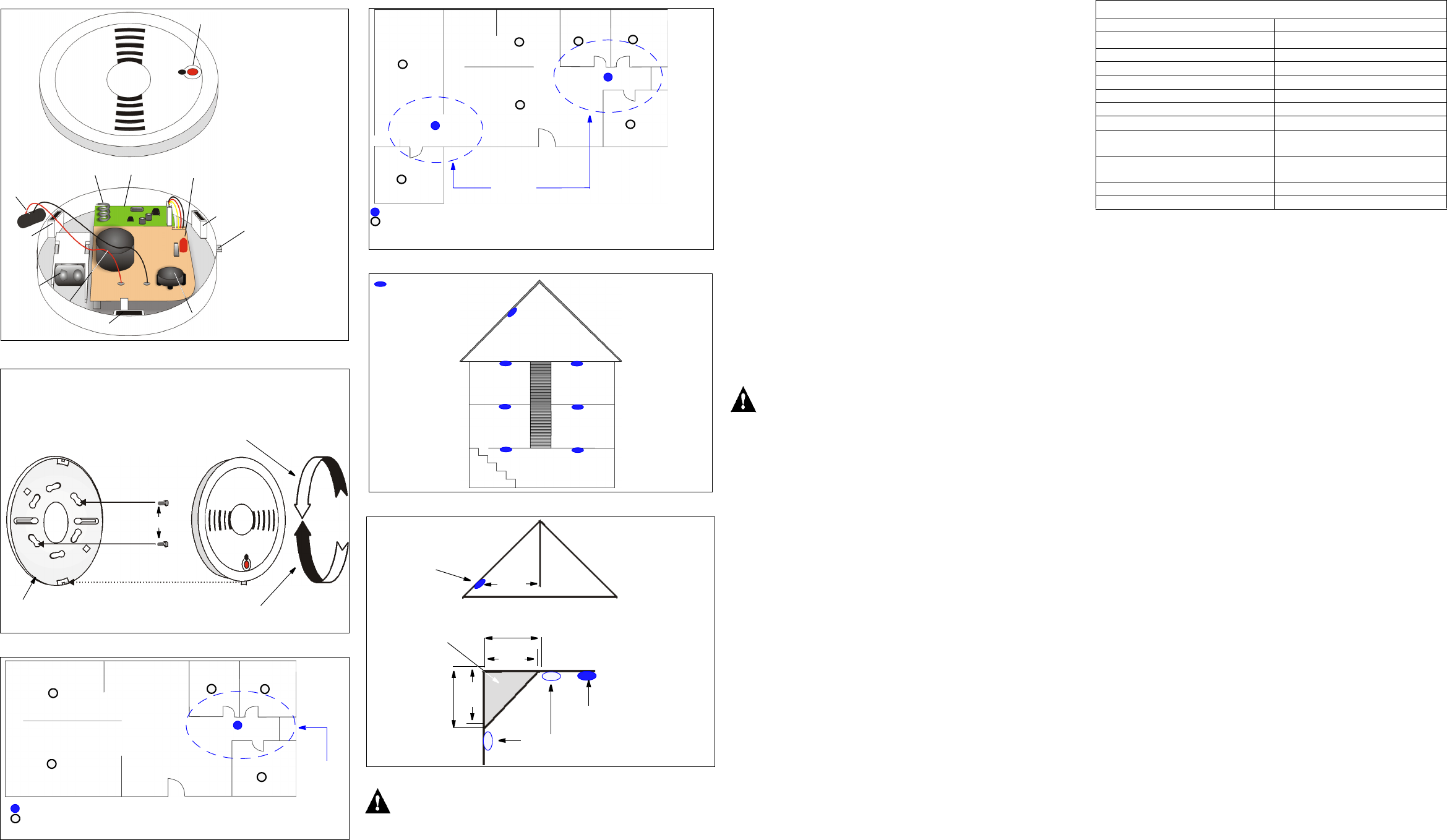
Figure 1: Detector Overview
Figure 2: Mounting
Figure 3: Single Residence with One Sleeping Area
Figure 4: Single Residence with Two Sleeping Areas
Figure 5: Locations for Multi-floor Residence
Figure 6: Alternative Mounting Locations
The following caution is required by the California State Fire Marshall:
“Early warning fire detection is best achieved by the installation of fire detection
equipment in all rooms and areas of the household as follows: (1) A smoke
detector installed in each sleeping area (in the vicinity, but outside of the
bedrooms) and (2) Heat or smoke detectors in the living rooms, dining rooms,
bedrooms, kitchens, hallways, attics, furnace rooms, closets, utility and storage
rooms, basements and attached garages.”
For your information, NFPA Standard 74, Section 2-4 reads as follows:
“2-4.1.1 Smoke detectors shall be installed outside of each separate sleeping
area in the immediate vicinity of the bedrooms and on each additional story of
the family living unit including basements and excluding crawl spaces and
unfinished attics.
The provisions of 2-4.1.1 represent the minimum number of detectors required
by this standard, It is recommended that the householder consider the use of
additional smoke detectors for increased protection for those areas separated by
a door from the areas protected by the required smoke detectors under 2-4.1.1
above. The recommended additional areas are living room, dining room,
bedroom(s), kitchen, attic (finished or unfinished), furnace rooms, utility room,
basement, integral or attached garage and hallways not included in 2-4.1.1
above. However, the use of additional remains the option of the householder.”
We recommend complete coverage and use of additional smoke detectors.
Locations to Install the Smoke Detector in Mobile Homes
and RVs
Mobile homes and RVs built after 1978 were designed and insulated to be
energy-efficient. In mobile homes and RVs built after 1978, smoke detectors
should be installed as outlined above. Older mobile homes and RVs may have
little or no insulation compared to current standards. Outside walls and roofs are
often made of non-insulated metal which can transfer thermal energy flow from
outdoors. This makes the air right next to them hotter or colder than the rest of
the inside air. These layers of hotter or colder air can keep smoke from reaching
the smoke detector. Therefore, install smoke detectors in such units only inside
walls. Place them between XCM (4”X) and XCM (6”) from the ceiling. If you are
not sure how much insulation is in your mobile home or RV, then install the
detector in each room for security. Before you install any detector, please read
the section “Detection Parameters” on page 1.
FCC Compliance Statement
Changes or modifications not expressly approved by Paradox Security
Systems could void your authority to use this equipment.
This equipment generates and uses radio frequency energy and if not installed
and used properly, in strict accordance with the manufacturer’s instructions, may
cause interference to radio or television reception. It has been type tested and
found to comply with the limits of Class B device in accordance with the
specifications in Subpart “B” if Part 15 of FCC Rules, which are designed to
provide reasonable protection against such interference in any residential
installation. However, there is no guarantee that interference will not occur in a
particular installation. If this equipment does cause interference to television or
radio reception, which can be determined by turning the equipment off and on,
the user is encouraged to try to correct the interference by one or more of the
following measures:
• Re-orient the receiving antenna.
• Relocate the alarm control with respect to the receiver.
• Move the alarm control away from the receiver.
• Connect the alarm control into a different outlet so that alarm control and
receiver are on different circuits.
If necessary, the user should consult the dealer or an experienced radio/
television technician for additional suggestions. The user may find the following
booklet prepared by the FCC helpful: “How to Identify and Resolve Radio/
Television Interference Problems”. This booklet is available from the U.S.
Government Printing Office, Washington, D.C. 20402, Stock # 004-000-00345-4.
Industry Canada Compliance Statement
This Class “B” digital apparatus meets all requirements of the Canadian
interference-causing equipment regulations.
IC: 2438A-0MnS7K1
“The term “IC:” before the radio certification number only signifies that Industry
Canada technical specifications were met.”
*The following batteries are acceptable for proper smoke detector operation:
Eveready #522, #1222, #216, Duracell #MN1604 and Gold Peak #1604P,
#1604S.
Specifications may change without prior notice.
For the latest information on product approvals, such as UL and CE, please visit our Web site at www.paradox.ca. One or more of
the following US patents may apply: 6215399, 611256, 5077549, 5751803, 5721542, 5287111, 5119069, and 5077549. LODIFF®
lens: patent #4,787,722 (U.S.). Canadian and International patents may also apply: LODIFF® a registered trademark of Fresnel
Technologies Inc. Digigard and Shield are trademarks of Paradox Security Systems.
Warranty
The Seller warrants its products to be free from defects in materials and workmanship under normal use for a period of one year.
Except as specifically stated herein, all express or implied warranties whatsoever, statutory or otherwise, including without
limitation, any implied warranty of merchantability and fitness for a particular purpose, are expressly excluded. Because Seller
does not install or connect the products and because the products may be used in conjunction with products not manufactured by
the Seller. Seller cannot guarantee the performance of the security system. Seller obligation and liability under this warranty is
expressly limited to repairing or replacing, at Seller’s option, any products not meeting the specifications. In no event shall the
Seller be liable to the buyer or any other person for any losses or damages whether direct or indirect or consequential or
incidental, including without limitation, any damages for lost profits stolen goods, or claims by any other party, caused by defective
goods or otherwise arising from the improper, incorrect or otherwise faulty installation or use of the merchandise sold.
© 2003 Paradox Security Systems Ltd.
A = Test button
B = Cover slots
C = Transmitter PCB
D = Antenna
E = Sensing chamber
F = Horn
G = LED
H = Battery connector
L = Lock tab
M = Battery
A
B
C
D
E
F
B
B
G
H
L
M
Turn counter-clockwise to lock to mounting
bracket.
Gently pull, then turn clockwise to unlock
from mounting bracket.
BA
C
D
D
1) Remove tamperproof thread from lock slot (A), then align with
preferred lock tab (B).
2) Insert screws (C) into preferred keyhole slots (D).
Mounting bracket
B
Dining Room Kitchen
Living Room
Bedroom
Bedroom Bedroom
= Detectors for minimum security.
= Detectors for additional
security.
Sleeping
area
Bedroom Bedroom
Bedroom
Bedroom
Family Room
Living Room
= Detectors for minimum security.
= Detectors for additional
security.
Kitchen Bedroom
Bedroom
Living Room
Kitchen
Bedroom
Bedroom
Family Room
Sleeping
areas
= Detectors for minimum
security.
Bedroom
Bedroom Study
Room
Bedroom
Basement
Kitchen
Center of ceiling
best location
Acceptable
location
Never
install in
this area
10cm
(4”)
10cm
(4”)
15cm
(6”)
15cm
(6”)
Horizontal distance
from peak
1m
(3.2ft)
Sloped ceiling
Corner
mounting
TECHNICAL SPECIFICATIONS
Detector Type
Power 9Vdc Alkaline battery*
Sensitivity 2.3±1.2%ft
Alarm Sound Output 85dB at (Xcm) (10ft)
Indicator Light Red LED flashed once every 45 sec.
Low Battery Life Up to 30 days
Relative Humidity 10% to 85%
Dimensions 140mm (5.5”) X 45mm (1.47”)
Supervisory Transmission Frequency
UL, ULC
64 minute intervals
Supervisory Transmission Frequency
ULC
12 minute intervals
Sounder Alarm Pattern UL, EU Evacuation temporal pattern
Sounder Alarm Pattern ULC Continuos beeps