Paradox Security Systems PARAKEYTX User Manual Parkei02
Paradox Security Systems Parkei02
Contents
- 1. USERS MANUAL
- 2. PROGRAMMING GUIDE
USERS MANUAL

Remote Arming Module V1.10
318MHz/433MHz
With
KEELOQ
high-security code encryption
Installer’s Guide
PARKEI-02
i i

TABLE OF CONTENTS
INTRODUCTION . . . . . . . . . . . . . . . . . . . . . . . . . . 2
1.1 Features . . . . . . . . . . . . . . . . . . . . . . . . . . . . . . . 2
1.2 Technical Specifications . . . . . . . . . . . . . . . . . . . . 3
INSTALLATION . . . . . . . . . . . . . . . . . . . . . . . . . . . 4
2.1 Location & Mounting . . . . . . . . . . . . . . . . . . . . . . 4
2.2 Power & Communication . . . . . . . . . . . . . . . . . . . 4
2.2.1 With Esprit Control Panel
. . . . . . . . . . . . . 4
2.2.2 Stand Alone
. . . . . . . . . . . . . . . . . . . . . . . 5
2.3 Keypad . . . . . . . . . . . . . . . . . . . . . . . . . . . . . . . . 5
2.4 Antenna. . . . . . . . . . . . . . . . . . . . . . . . . . . . . . . . 6
2.5 Programmable Outputs (PGMs) . . . . . . . . . . . . . . 6
2.6 Hand-Held Remote Control . . . . . . . . . . . . . . . . . 7
2.7 System Reset . . . . . . . . . . . . . . . . . . . . . . . . . . . 8
HOW TO PROGRAM . . . . . . . . . . . . . . . . . . . . . . 11
PROGRAMMING THE SYSTEM . . . . . . . . . . . . 13
4.1 Access Code Length . . . . . . . . . . . . . . . . . . . . . 13
4.2 Installer Code . . . . . . . . . . . . . . . . . . . . . . . . . . 13
4.3 User Parameters . . . . . . . . . . . . . . . . . . . . . . . . 13
4.3.1 User Access Codes
. . . . . . . . . . . . . . . . 14
4.3.2 Remote Control Assignment
. . . . . . . . . . 15
4.3.3 Remote Control Options
. . . . . . . . . . . . . 16
4.4 Panic Output Programming . . . . . . . . . . . . . . . . 17
4.5 Panic Lockout Timer . . . . . . . . . . . . . . . . . . . . . 18
4.6 PGM Output Timing . . . . . . . . . . . . . . . . . . . . . . 18
4.7 Button PGM Options . . . . . . . . . . . . . . . . . . . . . 19
4.8 Panic Option . . . . . . . . . . . . . . . . . . . . . . . . . . . 20
11

INTRODUCTION
The PARAKEY is a wireless remote control system that
consists of a receiving module and up to eight 2 or 4-button
remote controls (transmitters). When used in conjunction
with any
Paradox Esprit Series Control Panel
, remote
controls can perform actions such as remote arming and
disarming, communicating panic alarms and/or activating
programmable outputs (PGMs). Each remote control is
assigned to a specific user and therefore, identifies the user
to the control panel when used. If desired, it can be used as
a stand-alone system where the remote controls will only
activate the on-board PGM outputs. When a button on the
remote control is pressed, it will transmit an RF signal.
When the PARAKEY receives this signal, it then processes
the request and performs the programmed action(s).
• Simple, user-friendly programming.
• Supports 8 User Codes, each linked to a unique RF
Code (2 or 4-button remote control).
• Encrypted RF codes for additional security. Does not
use DIP switch programming.
• 4 programmable outputs (PGMs).
• Stand-alone operation (trigger PGMs only) or in
conjunction with a
Paradox Esprit Series Control Panel
(arm/disarm, panic & PGM activation).
• Programming keypad connects directly to the Parakey
Receiving Module.
• Programmable Installer Code.
• Software reset.
1.2.1 Receiver:
Compatible Programming Keypads: (616 V4.2A & up)
(626 V4.1A & up)
DC input: 12VDC
PGM outputs: 4
PGM Output 1-3 Current Rating: 30mA max.
PGM Output 4 Current Rating: 5A relay
Max Transmission Range: 53.34m (175 ft.)
Operating Conditions: 0°C to 50°C
Operating Humidity: 85%
Operating Frequency: 318 or 433.92MHz
Sensitivity: -110dbm
1.2.2 Remote Control:
Water Resistant
Battery:
Lithium 3V (CR2032)
Battery Life: Apprx. 2 years
Power Transmission: 7mW
Current Consumption:
6mA (transmission)
1.2 Technical Specifications
1.1 Features
2 3
INSTALLATION
We recommend installing the receiver in a centralized
location on the main floor. Avoid installing the receiver in
the basement. Although, if desired, it can be installed in
proximity of the control panel. When selecting an
installation site please take into consideration that the
maximum reception distance of the receiver is
approximately 54 meters (175 feet) line of sight. The circuit
is static sensitive, thus take great care during handling.
Avoid installing the receiving module near or in
the path of strong RF fields, such as neon lights
or computers. Also avoid installing the receiver
on or near metal objects, circuit breaker boxes,
air conditioners and heater ducts. These devices
may cause interference, reducing the receiver's
sensitivity.
If installing the Parakey away from the control panel, mount
the Parakey Receiver Module on a wall, leaving at least 2"
around the panel box to permit adequate ventilation/heat
dissipation. Selecting a site that is not susceptible to
drastic changes in temperature and humidity.
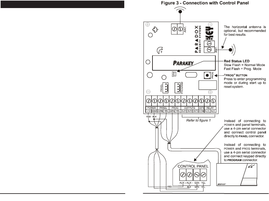
2.2.1 With Esprit Control Panel
When used in conjunction with any
Paradox Esprit Series
Control Panel
, the auxiliary terminals (12VDC) of the
control panel may power the Parakey Receiving Module
as shown in figure 3. If using an external power source
please ensure that the "GND" of the receiver and the
power source are connected to the "AUX-" terminal of the
control panel.
The "GRN" and "YEL" terminals of the control panel must
be connected to the "GRN" and "YEL" terminals of the
Parakey Receiving Module in order to provide
communication between the modules. Alternatively, you
can use a 4-pin serial connector between the control
panel's "SERVICE KEYPAD" connector and the Parakey
Module's "PANEL" connector.
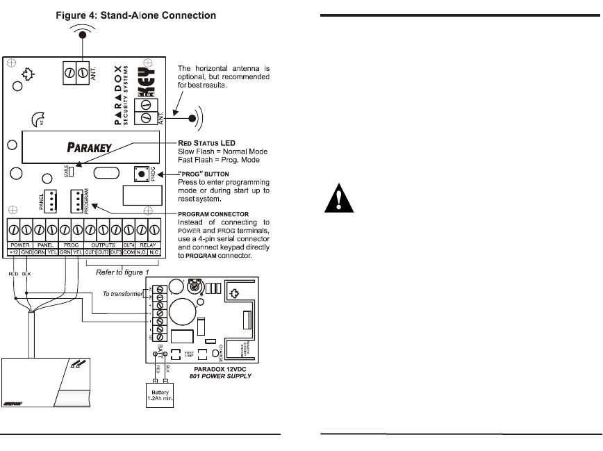
2.2.2 Stand Alone
When used as a stand-alone system, you will need a
Paradox 12VDC 801 Power Supply
and a 12VDC backup
battery. Connect the power supply and the backup
battery as shown in figure 4.
The Parakey Receiving Module is programmed using a
616 or 626 Esprit LED Keypad. Connect the keypad as
shown in figure 3 or 4. Alternatively, you can connect the
keypad to the Parakey Module's "PROGRAM" connector
using a 4-pin serial connector.
The Parakey can only be programmed using:
616 keypad version 4.2A and up or
626 keypad version 4.1A and up.
2.3 Keypad
2.2 Power & Communication
2.1 Location & Mounting
4 5
Firmly screw the vertical and horizontal antennas to the
corresponding "ANT" connections on the Receiving
Module as shown in figure 3 or 4. Use of the horizontal
antenna is optional, but is recommended for best results.
Do not cut, bend or alter the antenna in any way, as
this may reduce the receiver's sensitivity (range).
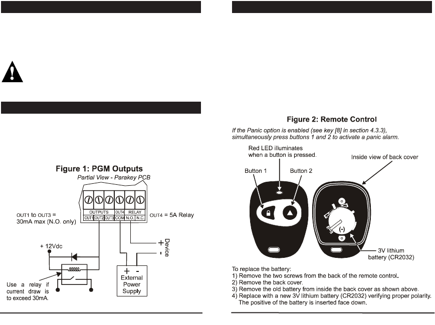
The Parakey provides four programmable outputs (OUT1 to
OUT4) each of which can be programmed for a variety of
home/office automation applications, such as opening a
garage door when button 1 is pressed on the remote control.
Please refer to figure 1 and section 4 for more information.
There are two types of hand-held PARAKEY remote
controls. There is a 2-button RF transmitter and a 4-
button RF transmitter. Each button can perform different
actions depending on how the system is programmed.
These remote controls can transmit a signal up to a
maximum of 54 meters (175ft). The remote controls are
powered by a 3V lithium battery. Occasionally this battery
must be changed as shown in figure 2. References to
button 3 and button 4 indicate keys on the 4-button
remote control only.
2.6 Hand-Held Remote Control
2.5 Programmable Outputs (PGMs)
2.4 Antenna
6 7
Performing a system reset will set the Parakey to default
settings. Please note that if connected to a control panel,
the reset sequence of the Parakey will not cause the
control panel to reset and vice versa. To execute a
system reset perform the following:
1) Remove the power connections ("+12" & "GND") from
the receiver.
2) Press and hold the “PROG” button and re-connect the
power connections to the receiver.
3) Wait approximately 2 seconds and release the “PROG“
button. The red LED will flash for 15 seconds, the
keypad will beep, and all system settings will be reset
to factory default.
2.7 System Reset
8 9
HOW TO PROGRAM
Press the [CLEAR] key at any time to revert to the preceding
step, unless entering data, in which case you will remain
in the section and the current data entry will be erased.
3.1.1 Step 1 - Enter the Programming Mode
When in "Normal Mode", the red LED on the Parakey
Receiver flashes on and off at 2-second intervals. To
enter the Programming Mode, press the "PROG" button
located on the Parakey Receiver. The program keypad
will beep once, the red LED will flash and the keypad's
"READY" light will illuminate.
If at any time you wait longer than 2 minutes
between each key entry, the Parakey will
automatically exit the Programming Mode.
3.1.2 Step 2 - Key in Installer Code
Press [ENTER] and key in the [INSTALLER CODE]. The [ENTER]
key will flash. Default installer code: [757575]
3.1.3 Step 3 - Key in Desired Section
Key in the desired 2-digit [SECTION] you wish to program.
The [ENTER] key will remain illuminated. The [2ND]key will
flash if the current section is empty. Pressing the [2ND]
key followed by the [ENTER]key will clear the contents of
the current section.
3.1.4 Step 4 - Key in the required data
• Sections [00] - [08]
Access Code Programming - Use any digits from 0
to 9 to enter the desired access code. When the
10 11
required data is entered, the keypad will emit a
confirmation beep and the Parakey will
automatically save and exit the section. If you make
a mistake, pressing [CLEAR] when entering data will
erase the current entry. Return to step 3 or press
[CLEAR] to exit Programming Mode.
• Sections [09] to [16]
RF Programming - Press the [ENTER] key and press
button 1 twice on the remote control to assign
remote control to corresponding user. The keypad
will emit a confirmation beep and the Parakey will
save and exit the section. Return to step 3 or press
[CLEAR] to exit Programming Mode.
• Sections [25] - [30]
Decimal Select - Each section represents one
feature and each key from [0] to [8] represents a
specific setting. Unlike feature select programming,
only one key can be selected. The selected key will
remain illuminated. Press the key representing the
desired setting and press [ENTER].
• Sections [17] - [24] & [31] - [35]
Feature Select - After entering the section, each key
from [1] to [8] represents a feature or option. The on/off
status of these keys determines the feature's setting.
Turn the keys on/off by pressing the appropriate key
until the desired options are set and press the [ENTER]
key. The keypad will emit a confirmation beep and the
Parakey will save and exit the section. Return to step
3 or press [CLEAR] to exit Programming Mode.
PROGRAMMING THE SYSTEM
Section [35] - Feature Select Programming: [1]
The Parakey can be set to accept 6-digit or 4-digit User
and Installer Access Codes.
Key [1] OFF = 4-digit access codes.
Key [1] ON = 6-digit access codes (default).
This option must be set to the same access code
length as set in the control panel at address 088,
key [9].
Section [00] - Access Code Programming
The Installer Code provides you with access to program
all the functions & features of the Parakey System. The
Installer Code can be 4 or 6 digits in length (see section
4.1) with each digit being any value from 0 to 9.
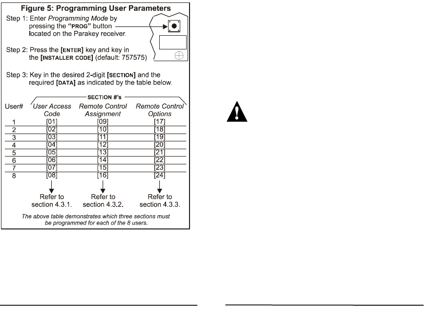
The Parakey system supports up to eight users, each with a
different remote control. As demonstrated in figure 5, the
three parameters listed below are specific to each user and
each user must be defined with all three of these parameters.
• User Access Code
• Remote Control Assignment
• User Remote Control Options
4.3 User Parameters
4.2 Installer Code (Default: 757575)
4.1 Access Code Length
12 13
4.3.1 User Access Codes
Sections [01] to [08] - Access Code Programming
When a user presses a button, the Parakey determines
which user the remote control belongs to and transmits the
corresponding User Access Code to the control panel. To
arm/disarm the system, the
Paradox Esprit Series Control
Panel
must receive a valid access code. Therefore, the
programmed User Access Code must be the same as a
User Access Code programmed in the
Paradox Esprit
Series Control Panel
. If no access code is programmed,
only the programmed PGMs will be activated. The User
Access Codes can be 4 or 6 digits in length (see section 4.1)
with each digit being any value from 0 to 9. Program the
User Access Code into the section corresponding to the
desired user, where sections [01] to [08] represent users 1
through 8 respectively (figure 5).
The User Access Code programmed in the
Parakey must be the same as a User Access
Code programmed in the Paradox Esprit Series
Control Panel.
4.3.2 Remote Control Assignment
Sections [09] to [16] - RF Programming
Every time a button is pressed on the remote control, it
transmits its RF code to the Parakey, identifying it as a user
in the system. Therefore, each remote control in the
system must be assigned to a user. After entering the
section corresponding to the desired user (see figure 5),
press the [ENTER] key and the “READY” and “ARM” lights will
illuminate. Then press button 1 on the remote control once,
the Parakey will beep once. Press button 1 again for
confirmation, the Parakey will beep twice to indicate that
the remote control was successfully assigned. One long
beep indicates that remote control assignment was
unsuccessful (i.e. remote control already assigned to
another user). To delete a remote control, enter the desired
section, press the [2ND] key and press the [ENTER] key.
14 15
4.3.3 Remote Control Options
Sections [17] to [24] - Feature Select: [1] to [8]
As described in figure 5, sections [17] to [24] correspond
to users 1 through 8 respectively. By turning keys [1] to
[8] on or off, set the desired remote control options as
described below and press [ENTER].
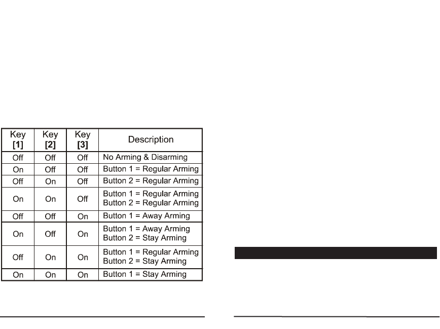
Buttons 1 and 2 on the remote controls can be set to perform
different arming and disarming actions when pressed,
depending on the setting of keys [1] to [3] as shown in the
table below. (Default: Button 1 = Regular Arming)
Each key from [4] to [7] represents buttons 1 through 4
respectively. When the key is enabled, pressing the
corresponding button will activate (toggle) any PGMs defined
by the
Button PGM Options
(section 4.7). Default all ON.
Key [4] OFF = Disabled
ON = Button 1 PGM Enabled
Key [5] OFF = Disabled
ON = Button 2 PGM Enabled
Key [6] OFF = Disabled
ON = Button 3 PGM Enabled
(4-button remote only)
Key [7] OFF = Disabled
ON = Button 4 PGM Enabled
(4-button remote only)
When the [8] key is enabled, pressing any two buttons
simultaneously on the remote control will generate a
panic alarm (see sections 4.4, 4.5 and 4.8)
Key [8] OFF = Panic Disabled
ON = Panic Enabled (Default)
Section [25] - Decimal Select: [0] to [4]
When a remote control-activated panic alarm is generated
(see section 4.3.3), the Parakey can activate one of the four
on-board PGM outputs. In section [25], select only one:
4.4 Panic Output Programming
16 17
Section [25]
Key [0] ON = No output on panic alarm
Key [1] ON = Toggle output 1 on panic alarm
Key [2] ON = Toggle output 2 on panic alarm
Key [3] ON = Toggle output 3 on panic alarm (default)
Key [4] ON = Toggle output 4 on panic alarm
Section [26] - Decimal Select: [0] to [4]
When a remote control-activated panic alarm is
generated (see section 4.3.3), the Parakey can ignore
any incoming RF signals for a specified period. This
prevents an aggressor from disarming the system in case
of a panic situation. In section [26], select only one:
Section [26]
Key [0] ON = No signal lock-out on panic alarm (default)
Key [1] ON = 30 second signal lockout on panic alarm
Key [2] ON = 60 second signal lockout on panic alarm
Key [3] ON = 90 second signal lockout on panic alarm
Key [4] ON = 120 second signal lockout on panic alarm
Section [27] to [30] - Decimal Select: [0] to [8]
When any of the PGM outputs are activated (see section
4.3.3 & 4.4), the Parakey can latch the output in its
opposite state until the output is toggled again or for a
specified period of time. At the end of this period, the
output will return to its normal state. Each PGM output
can be programmed with a separate output timer. In the
section corresponding to the desired PGM output, where
sections [27] to [30] represent PGM outputs 1 through 4
respectively, select the desired output timer.
Key [0] ON = Latched Key [5] ON = 40 sec.
Key [1] ON = 1 sec. Key [6] ON = 60 sec.
Key [2] ON = 5 sec. (default) Key [7] ON = 2 min.
Key [3] ON = 10 sec. Key [8] ON = 4 min.
Key [4] ON = 20 sec.
Sections [31] to [34] - Feature Select: [1] to [4]
This feature allows you to determine which PGM outputs
a PGM enabled button will activate (see section 4.3.3).
Please note that this feature is a global feature.
For example, if button 1 is programmed to toggle
PGM outputs 1 and 2, then button 1 on all the
remote controls will toggle PGM outputs 1 and 2.
In the section corresponding to the desired button, where
sections [31] to [34] represent buttons 1 through 4
respectively, select which outputs will be triggered.
OFF Key ON
Disabled [1] Activate Output 1
Disabled [2] Activate Output 2
Disabled [3] Activate Output 3
Disabled [4] Activate Output 4
4.7 Button PGM Options
4.6 PGM Output Timing
4.5 Panic Lockout Timer
18 19

Section [35] - Feature Select: [2]
When a remote control-activated panic alarm is
generated (see section 4.3.3), the Parakey can perform
one of two actions:
Key [2] OFF = Panics generated from the remote control
will only toggle the enabled PGM output
(see section 4.4).
Key [2] ON = Panics generated from the remote control
will toggle any enabled PGM outputs (see
section 4.4) and sends the Panic
command to the control panel generating
a Panic alarm on the control panel.
Warranty
The Seller warrants its products to be free from defects in
materials and workmanship under normal use for a
period of one year. Except as specifically stated herein,
all express or implied warranties whatsoever, statutory or
otherwise, including without limitation, any implied
warranty of merchantability and fitness for a particular
purpose, are expressly excluded. Because Seller does
not install or connect the products and because the
products may be used in conjunction with products not
manufactured by Seller. Seller cannot guarantee the
performance of the security system. Seller obligation and
liability under this warranty is expressly limited to
repairing or replacing, at Seller's option, any product not
meeting the specifications. In no event shall the Seller be
liable to the buyer or any other person for any loss or
damages whether direct or indirect or consequential or
incidental, including without limitation, any damages for
lost profits stolen goods, or claims by any other party,
caused by defective goods or otherwise arising from the
improper, incorrect or otherwise faulty installation or use
of the merchandise sold.
FCC Warnings
This device complies with part 15 of the FCC Rules.
Operation is subject to the followintg two conditions: (1)
this device may not cause interference, and (2) this
device must accept any interference, including
interference that may cause undesired operation of the
device.
4.8 Panic Option
20