Paradyne 6381 A3 Users Manual Router User’s Guide
6381-A2-GB23-10 6381-A2-GB23-10
6381-A2-GB23-10 6381-A2-GB23-10
6381-A3 to the manual 86a4be14-c46e-4cd1-8f4d-682c7df8c894
2015-02-06
: Paradyne Paradyne-6381-A3-Users-Manual-516572 paradyne-6381-a3-users-manual-516572 paradyne pdf
Open the PDF directly: View PDF ![]() .
.
Page Count: 78
- Contents
- About This Guide
- Introduction
- Hardware Installation and PC Setup
- Using the Web Interface
- Troubleshooting
- Terminology
- Index

6381-A3 Router
User’s Guide
Document No. 6381-A2-GB23-10
January 2005

A January 2005 6381-A2-GB23-10
Copyright © 2005 Paradyne Corporation.
All rights reserved.
Printed in U.S.A.
Notice
This publication is protected by federal copyright law. No part of this publication may be copied or distributed,
transmitted, transcribed, stored in a retrieval system, or translated into any human or computer language in any form or
by any means, electronic, mechanical, magnetic, manual or otherwise, or disclosed to third parties without the express
written permission of Paradyne Corporation, 8545 126th Ave. N., Largo, FL 33773.
Paradyne Corporation makes no representation or warranties with respect to the contents hereof and specifically
disclaims any implied warranties of merchantability or fitness for a particular purpose. Further, Paradyne Corporation
reserves the right to revise this publication and to make changes from time to time in the contents hereof without
obligation of Paradyne Corporation to notify any person of such revision or changes.
Changes and enhancements to the product and to the information herein will be documented and issued as a new
release to this manual.
Warranty, Sales, Service, and Training Information
Contact your local sales representative, service representative, or distributor directly for any help needed. For additional
information concerning warranty, sales, service, repair, installation, documentation, training, distributor locations, or
Paradyne worldwide office locations, use one of the following methods:
Internet: Visit the Paradyne World Wide Web site at www.paradyne.com. (Be sure to register your warranty at
www.paradyne.com/warranty.)
Telephone: Call our automated system to receive current information by fax or to speak with a company
representative.
— Within the U.S.A., call 1-800-870-2221
— Outside the U.S.A., call 1-727-530-2340
Document Feedback
We welcome your comments and suggestions about this document. Please mail them to Technical Publications,
Paradyne Corporation, 8545 126th Ave. N., Largo, FL 33773, or send e-mail to userdoc@paradyne.com. Include the
number and title of this document in your correspondence. Please include your name and phone number if you are
willing to provide additional clarification.
Trademarks
Acculink, Bitstorm, Comsphere, DSL the Easy Way, ETC, Etherloop, FrameSaver, GranDSLAM, GrandVIEW, Hotwire,
the Hotwire logo, iMarc, Jetstream, MVL, NextEDGE, Net to Net Technologies, OpenLane, Paradyne, the Paradyne
logo, Paradyne Credit Corp., the Paradyne Credit Corp. logo, Performance Wizard, ReachDSL, StormPort, TruePut are
registered trademarks of Paradyne Corporation.
ADSL/R, Connect to Success, Hotwire Connected, JetFusion, JetVision, MicroBurst, PacketSurfer, Quick Channel,
Reverse Gateway, Spectrum Manager, and StormTracker are trademarks of Paradyne Corporation.
All other products or services mentioned herein are the trademarks, service marks, registered trademarks, or
registered service marks of their respective owners.

6381-A2-GB23-10 January 2005 B
Important Safety Instructions
1. Read and follow all warning notices and instructions marked on the product or included in the manual.
2. Slots and openings in the cabinet are provided for ventilation. To ensure reliable operation of the product and to
protect it from overheating, these slots and openings must not be blocked or covered.
3. Do not allow anything to rest on the power cord and do not locate the product where persons will walk on the power
cord.
4. Do not attempt to service this product yourself, as opening or removing covers may expose you to dangerous high
voltage points or other risks. Refer all servicing to qualified service personnel.
5. General purpose cables are used with this product for connection to the network. Special cables, which may be
required by the regulatory inspection authority for the installation site, are the responsibility of the customer. Use a
UL Listed, CSA certified, minimum No. 24 AWG line cord for connection to the Digital Subscriber Line (DSL)
network.
6. When installed in the final configuration, the product must comply with the applicable Safety Standards and
regulatory requirements of the country in which it is installed. If necessary, consult with the appropriate regulatory
agencies and inspection authorities to ensure compliance.
7. A rare phenomenon can create a voltage potential between the earth grounds of two or more buildings. If products
installed in separate buildings are interconnected, the voltage potential may cause a hazardous condition. Consult
a qualified electrical consultant to determine whether or not this phenomenon exists and, if necessary, implement
corrective action prior to interconnecting the products.
8. Input power to this product must be provided by one of the following: (1) a UL Listed/CSA certified power source
with a Class 2 or Limited Power Source (LPS) output for use in North America, or (2) a certified transformer, with a
Safety Extra Low Voltage (SELV) output having a maximum of 240 VA available, for use in the country of
installation.
9. In addition, since the equipment is to be used with telecommunications circuits, take the following precautions:
— Never install telephone wiring during a lightning storm.
— Never install telephone jacks in wet locations unless the jack is specifically designed for wet locations.
— Never touch uninsulated telephone wires or terminals unless the telephone line has been disconnected at the
network interface.
— Use caution when installing or modifying telephone lines.
— Avoid using a telephone (other than a cordless type) during an electrical storm. There may be a remote risk of
electric shock from lightning.
— Do not use the telephone to report a gas leak in the vicinity of the leak.
CE Marking
When the product is marked with the CE mark on the equipment label, a supporting Declaration of Conformity may be
downloaded from the Paradyne World Wide Web site at www.paradyne.com. Select Library → Technical Manuals →
CE Declarations of Conformity.
FCC Part 15 Declaration
An FCC Declaration of Conformity may be downloaded from the Paradyne World Wide Web site at www.paradyne.com.
Select Support -> Technical Manuals -> Declarations of Conformity.
This device complies with Part 15 of the FCC Rules. Operation is subject to the following two conditions: (1) this device
may not cause harmful interference, and (2) this device must accept any interference received, including interference
that may cause undesired operation.
The authority to operate this equipment is conditioned by the requirement that no modifications will be made to the
equipment unless the changes or modifications are expressly approved by the responsible party.
!

C January 2005 6381-A2-GB23-10
This equipment has been tested and found to comply with the limits for a Class B digital device, pursuant to Part 15 of
the FCC Rules. These limits are designed to provide reasonable protection against harmful interference in a residential
installation. This equipment generates, uses, and can radiate radio frequency energy and, if not installed and used in
accordance with the instructions, may cause harmful interference to radio communications. However, there is no
guarantee that interference will not occur in a particular installation. If this equipment does cause harmful interference
to radio or television reception, which can be determined by turning the equipment off and on, the user is encouraged to
try to correct the interference by one or more of the following measures:
Reorient or relocate the receiving antenna.
Increase the separation between the equipment and receiver.
Connect the equipment into an outlet on a circuit different from that to which the receiver is connected.
Consult the dealer or an experienced radio/TV technician for help.
Notice to Users of the United States Telephone Network
The following notice applies to versions of the modem that have been FCC Part 68 approved.
This equipment complies with Part 68 of the FCC rules and the requirements adopted by the Administrative Council for
Terminal Attachment (ACTA). On the bottom side of this equipment is a label that contains, among other information, a
product identifier in the format US:AAAEQ##TXXXX. If requested, this number must be provided to the Telephone
Company.
This equipment is intended to connect to the Public Switched Telephone Network through a Universal Service Order
Code (USOC) type RJ11C jack. A plug and jack used to connect this equipment to the premises wiring and telephone
network must comply with the applicable FCC Part 68 rules and requirements adopted by the ACTA. A compliant
telephone cord and modular plug is provided with this product. It has been designed to be connected to a compatible
modular jack that is also compliant.
The Ringer Equivalence Number (or REN) is used to determine the number of devices that may be connected to a
telephone line. Excessive RENs on a telephone line may result in the devices not ringing in response to an incoming
call. In most but not all areas, the sum of RENs should not exceed five (5.0). To be certain of the number of devices that
may be connected to a line, as determined by the total RENs, contact the local Telephone Company. The REN for this
product is part of the product identifier that has the format US:AAAEQ##TXXXX. The digits represented by ## are the
REN without a decimal point. For example, 03 represents a REN of 0.3.
If the modem causes harm to the telephone network, the Telephone Company will notify you in advance that temporary
discontinuance of service may be required. But if advance notice is not practical, the Telephone Company will notify the
customer as soon as possible. Also, you will be advised of your right to file a complaint with the FCC if you believe it is
necessary.
The Telephone Company may make changes in its facilities, equipment, operations or procedures that could affect the
operation of the equipment. If this happens, the Telephone Company will provide advance notice in order for you to
make necessary modifications to maintain uninterrupted service. If trouble is experienced with the modem, refer to the
repair and warranty information in this document.
If the equipment is causing harm to the telephone network, the Telephone Company may request that you disconnect
the equipment until the problem is resolved.
The user may make no repairs to the equipment.
Connection to party line service is subject to state tariffs. Contact the state public utility commission, public service
commission or corporation commission for information.
If the site has specially wired alarm equipment connected to the telephone line, ensure the installation of the modem
does not disable the alarm equipment. If you have questions about what will disable alarm equipment, consult your
Telephone Company or a qualified installer.

6381-A2-GB23-10 January 2005 D
Supplier's Declaration of Conformity
Place of Issue:
Paradyne Corporation
8545 126th Avenue North
Largo, FL 33773-1502
USA
Date of Issue: 4/2/2004
Paradyne Corporation, located at the above address, hereby certifies that Model Number 6381-A2-210, bearing
labeling identification number US:AW2DL03B6381-AX, complies with: the Federal Communications Commission's
("FCC") Rules and Regulations 47 CFR Part 68, the Administrative Council on Terminal Attachments ("ACTA")-adopted
technical criteria TIA-968-A, "Telecommunications - Telephone Terminal Equipment -Technical Requirements for
Connection of Terminal Equipment To the Telephone Network, October 2002."
Patrick Murphy
Senior Vice President, Chief Financial Officer
Notice to Users of the Canadian Telephone Network
NOTICE: This equipment meets the applicable Industry Canada Terminal Equipment Technical Specifications. This is
confirmed by the registration number. The abbreviation IC before the registration number signifies that registration was
performed based on a Declaration of Conformity indicating that Industry Canada technical specifications were met. It
does not imply that Industry Canada approved the equipment.
NOTICE: The Ringer Equivalence Number (REN) for this terminal equipment is labeled on the equipment. The REN
assigned to each terminal equipment provides an indication of the maximum number of terminals allowed to be
connected to a telephone interface. The termination on an interface may consist of any combination of devices subject
only to the requirement that the sum of the Ringer Equivalence Numbers of all the devices does not exceed five.
If your equipment is in need of repair, contact your local sales representative, service representative, or distributor
directly.
CANADA - EMI NOTICE:
This Class B digital apparatus meets all requirements of the Canadian interference-causing equipment regulations.
Cet appareil numérique de la classe B respecte toutes les exigences du règlement sur le matérial brouilleur du
Canada.
!

E January 2005 6381-A2-GB23-10
Japan Notices
This is a Class B product based on the standard of the Voluntary Control Council for
Interference from Information Technology Equipment (VCCI). If this is used near a radio or
television receiver in a domestic environment, it may cause radio interference. Install and use
the equipment according to the instruction manual.

6381-A2-GB23-10 January 2005 i
Contents
About This Guide
Document Purpose and Intended Audience . . . . . . . . . . . . . . . . . . . . v
Document Summary . . . . . . . . . . . . . . . . . . . . . . . . . . . . . . . . . . . . . . v
Product-Related Documents . . . . . . . . . . . . . . . . . . . . . . . . . . . . . . . . vi
1 Introduction
Definitions . . . . . . . . . . . . . . . . . . . . . . . . . . . . . . . . . . . . . . . . . . . . . . 1-1
Features of the 6381 Router . . . . . . . . . . . . . . . . . . . . . . . . . . . . . . . . 1-1
System Requirements . . . . . . . . . . . . . . . . . . . . . . . . . . . . . . . . . . . . . 1-2
Ports and Buttons (Back Panel) . . . . . . . . . . . . . . . . . . . . . . . . . . . . . . 1-2
LED Description (Front Panel) . . . . . . . . . . . . . . . . . . . . . . . . . . . . . . . 1-3
Packing List . . . . . . . . . . . . . . . . . . . . . . . . . . . . . . . . . . . . . . . . . . . . . 1-4
2 Hardware Installation and PC Setup
Overview . . . . . . . . . . . . . . . . . . . . . . . . . . . . . . . . . . . . . . . . . . . . . . . 2-1
Connecting the Hardware . . . . . . . . . . . . . . . . . . . . . . . . . . . . . . . . . . 2-1
Configuring Your PC . . . . . . . . . . . . . . . . . . . . . . . . . . . . . . . . . . . . . . 2-3
Windows USB Driver Installation . . . . . . . . . . . . . . . . . . . . . . . . . . . . . 2-3
Configuring Your PC’s IP Address . . . . . . . . . . . . . . . . . . . . . . . . . . . . 2-6
Assigning an IP Address to your PC Automatically by DHCP . . . . 2-6
Windows XP . . . . . . . . . . . . . . . . . . . . . . . . . . . . . . . . . . . . . . . . . 2-6
Windows 2000 . . . . . . . . . . . . . . . . . . . . . . . . . . . . . . . . . . . . . . . . 2-8
Windows ME . . . . . . . . . . . . . . . . . . . . . . . . . . . . . . . . . . . . . . . . . 2-9
Windows 95, 98 . . . . . . . . . . . . . . . . . . . . . . . . . . . . . . . . . . . . . . . 2-10
Windows NT 4.0 . . . . . . . . . . . . . . . . . . . . . . . . . . . . . . . . . . . . . . 2-11
3 Using the Web Interface
Logging Into Your Router . . . . . . . . . . . . . . . . . . . . . . . . . . . . . . . . . . . 3-1
Home Page . . . . . . . . . . . . . . . . . . . . . . . . . . . . . . . . . . . . . . . . . . . . . 3-2
Quick Start . . . . . . . . . . . . . . . . . . . . . . . . . . . . . . . . . . . . . . . . . . . . . . 3-2

Contents
ii January 2005 6381-A2-GB23-10
Setup . . . . . . . . . . . . . . . . . . . . . . . . . . . . . . . . . . . . . . . . . . . . . . . . . . 3-5
Wide Area Network Connection. . . . . . . . . . . . . . . . . . . . . . . . . . . 3-5
Local Area Network Connection . . . . . . . . . . . . . . . . . . . . . . . . . . 3-5
Saving Changes . . . . . . . . . . . . . . . . . . . . . . . . . . . . . . . . . . . . . . 3-5
Configuring the WAN . . . . . . . . . . . . . . . . . . . . . . . . . . . . . . . . . . . . . . 3-6
New Connection. . . . . . . . . . . . . . . . . . . . . . . . . . . . . . . . . . . . . . . . . . 3-7
PPPoE Connection Setup . . . . . . . . . . . . . . . . . . . . . . . . . . . . . . . 3-7
PPPoA Connection Setup . . . . . . . . . . . . . . . . . . . . . . . . . . . . . . . 3-9
Static Connection Setup . . . . . . . . . . . . . . . . . . . . . . . . . . . . . . . . 3-11
DHCP Connection Setup . . . . . . . . . . . . . . . . . . . . . . . . . . . . . . . . 3-12
Bridged Connection . . . . . . . . . . . . . . . . . . . . . . . . . . . . . . . . . . . . 3-13
CLIP Connection . . . . . . . . . . . . . . . . . . . . . . . . . . . . . . . . . . . . . . 3-15
Modify an Existing Connection. . . . . . . . . . . . . . . . . . . . . . . . . . . . . . . 3-16
Modem Setup. . . . . . . . . . . . . . . . . . . . . . . . . . . . . . . . . . . . . . . . . . . . 3-17
TSML . . . . . . . . . . . . . . . . . . . . . . . . . . . . . . . . . . . . . . . . . . . . . . . . . . 3-17
Configuring the LAN. . . . . . . . . . . . . . . . . . . . . . . . . . . . . . . . . . . . . . . 3-18
Enable/Disable DHCP . . . . . . . . . . . . . . . . . . . . . . . . . . . . . . . . . . 3-19
Changing the Router's IP address . . . . . . . . . . . . . . . . . . . . . . . . . . . . 3-20
Firewall/NAT Services . . . . . . . . . . . . . . . . . . . . . . . . . . . . . . . . . . . . . 3-21
Advanced . . . . . . . . . . . . . . . . . . . . . . . . . . . . . . . . . . . . . . . . . . . . . . . 3-22
UPnP . . . . . . . . . . . . . . . . . . . . . . . . . . . . . . . . . . . . . . . . . . . . . . . 3-22
SNTP . . . . . . . . . . . . . . . . . . . . . . . . . . . . . . . . . . . . . . . . . . . . . . . 3-23
SNMP . . . . . . . . . . . . . . . . . . . . . . . . . . . . . . . . . . . . . . . . . . . . . . 3-24
IP QoS . . . . . . . . . . . . . . . . . . . . . . . . . . . . . . . . . . . . . . . . . . . . . . 3-25
Port Forwarding . . . . . . . . . . . . . . . . . . . . . . . . . . . . . . . . . . . . . . . 3-25
IP Filters. . . . . . . . . . . . . . . . . . . . . . . . . . . . . . . . . . . . . . . . . . . . . 3-27
LAN Clients . . . . . . . . . . . . . . . . . . . . . . . . . . . . . . . . . . . . . . . . . . 3-28
LAN Isolation . . . . . . . . . . . . . . . . . . . . . . . . . . . . . . . . . . . . . . . . . 3-28
Bridge Filters . . . . . . . . . . . . . . . . . . . . . . . . . . . . . . . . . . . . . . . . . 3-29
Multicast. . . . . . . . . . . . . . . . . . . . . . . . . . . . . . . . . . . . . . . . . . . . . 3-31
IGMP Snooping . . . . . . . . . . . . . . . . . . . . . . . . . . . . . . . . . . . . . . . 3-32
Static Routing . . . . . . . . . . . . . . . . . . . . . . . . . . . . . . . . . . . . . . . . 3-32
Dynamic Routing . . . . . . . . . . . . . . . . . . . . . . . . . . . . . . . . . . . . . . 3-33
Access Control. . . . . . . . . . . . . . . . . . . . . . . . . . . . . . . . . . . . . . . . 3-35
Log Out . . . . . . . . . . . . . . . . . . . . . . . . . . . . . . . . . . . . . . . . . . . . . . . . 3-35

Contents
6381-A2-GB23-10 January 2005 iii
Tools . . . . . . . . . . . . . . . . . . . . . . . . . . . . . . . . . . . . . . . . . . . . . . . . . . 3-36
System Commands . . . . . . . . . . . . . . . . . . . . . . . . . . . . . . . . . . . . 3-36
Remote Log . . . . . . . . . . . . . . . . . . . . . . . . . . . . . . . . . . . . . . . . . . 3-36
User Management . . . . . . . . . . . . . . . . . . . . . . . . . . . . . . . . . . . . . 3-37
Update Gateway . . . . . . . . . . . . . . . . . . . . . . . . . . . . . . . . . . . . . . 3-38
Analyzer. . . . . . . . . . . . . . . . . . . . . . . . . . . . . . . . . . . . . . . . . . . . . 3-39
Ping Test . . . . . . . . . . . . . . . . . . . . . . . . . . . . . . . . . . . . . . . . . . . . 3-39
Modem Test. . . . . . . . . . . . . . . . . . . . . . . . . . . . . . . . . . . . . . . . . . 3-40
Status . . . . . . . . . . . . . . . . . . . . . . . . . . . . . . . . . . . . . . . . . . . . . . . . . . 3-41
4 Troubleshooting
The Router Is Not Functional . . . . . . . . . . . . . . . . . . . . . . . . . . . . . . . . 4-1
You Cannot Connect to the Router . . . . . . . . . . . . . . . . . . . . . . . . . . . 4-1
LEDs Blink in a Sequential Pattern . . . . . . . . . . . . . . . . . . . . . . . . . . . 4-2
The Status LED Continues to Blink . . . . . . . . . . . . . . . . . . . . . . . . . . . 4-2
The Status LED is Always Off . . . . . . . . . . . . . . . . . . . . . . . . . . . . . . . 4-2
A Terminology
What is a Firewall?. . . . . . . . . . . . . . . . . . . . . . . . . . . . . . . . . . . . . . . . A-1
What is NAT? . . . . . . . . . . . . . . . . . . . . . . . . . . . . . . . . . . . . . . . . . . . . A-1
What is a DMZ? . . . . . . . . . . . . . . . . . . . . . . . . . . . . . . . . . . . . . . . . . . A-1
What is a Router? . . . . . . . . . . . . . . . . . . . . . . . . . . . . . . . . . . . . . . . . A-2
Index

Contents
iv January 2005 6381-A2-GB23-10
6381-A2-GB23-10 January 2005 v
About This Guide
Document Purpose and Intended Audience
This guide contains detailed information about the 6381-A3 router. It is intended
for all users of the router.
Document Summary
A master glossary of terms and acronyms used in Paradyne documents is
available online at www.paradyne.com. Select Support → Technical Manuals →
Technical Glossary.
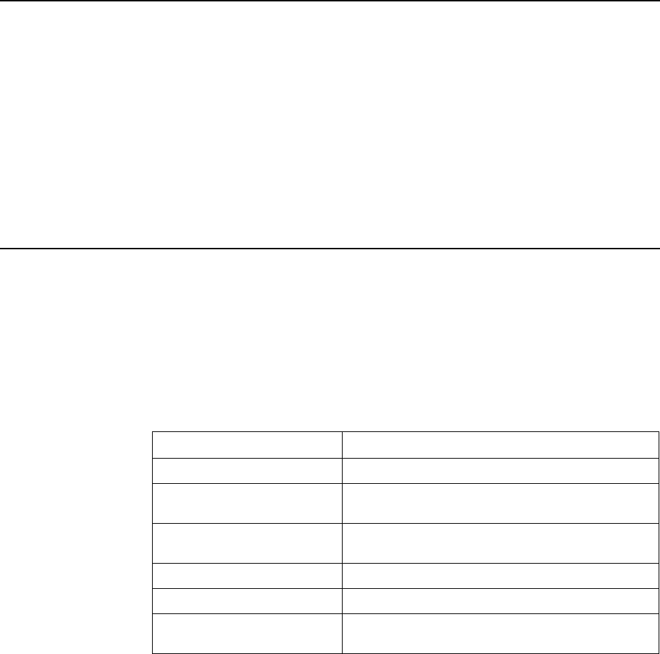
Section Description
Chapter 1, Introduction Describes the features of the router.
Chapter 2, Hardware
Installation and PC Setup
Shows how to connect the router and set up your PC to
manage the router.
Chapter 3, Using the Web
Interface
Explains how to use the web interface to configure and
monitor the router.
Chapter 4, Troubleshooting Contains tips on troubleshooting common problems.
Appendix A, Terminology Explains some major internetworking concepts.
Index Lists key terms, concepts, and sections in alphabetical
order.

About This Guide
vi January 2005 6381-A2-GB23-10
Product-Related Documents
Complete documentation for Paradyne products is available online at
www.paradyne.com. Select Support → Technical Manuals.
To order a paper copy of a Paradyne document, or to speak with a sales
representative, please call 1-727-530-2000.

6381-A2-GB23-10 January 2005 1-1
1
Introduction
Definitions
Before you install or use your new router, you may find it helpful to understand the
following terms:
A bridge is a device that forwards any message from one part of a network to
another.
A router is a device that forwards messages according to their network
addresses.
ADSL is Asymmetric Digital Subscriber Line, a version of DSL that allows a
higher speed for information coming from the Internet to your PC
(“downstream”) than it does for information going to the Internet from your PC
(“upstream”).
ReachDSL is a version of DSL that works on lines too long or too noisy for
ADSL.
ADSL/R is technology that combines ADSL and ReachDSL in one device.
The Model 6381 is a Digital Subscriber Line (DSL) modem that may be set by you
to run in bridge or router mode. Because it is most frequently used as a router, that
is how it is referred to in this manual. It supports ADSL/R.
Features of the 6381 Router
Your router has the following features:
Support for ADSL2+ and ReachDSL (ADSL/R)
10/100BaseT Ethernet port
USB port
The ability to connect multiple PCs to the Internet with just one WAN IP
Address (when configured in router mode with NAT enabled)
A user-friendly web interface for configuration and monitoring
Single-session IPSec and PPTP passthrough for Virtual Private Network
(VPN)

1. Introduction
1-2 January 2005 6381-A2-GB23-10
Preconfigured port settings for many popular games
Ability to act as a DHCP Server on your network
Compatibility with virtually all standard Internet applications
Address filtering and DMZ hosting
Downloadable flash software upgrades
Support for up to eight Permanent Virtual Circuits (PVCs)
Support for up to two PPPoE sessions
System Requirements
In order to use your modem for Internet access, you must have the following:
ADSL service subscription from your ISP.
One computer with an Ethernet 10/100BaseT network interface card (NIC) or
a free USB port.
(Optional) An Ethernet hub or switch, if you are connecting the device to
several computers on an Ethernet network.
For system monitoring or configuration using the supplied web interface, a
web browser such as Internet Explorer Version 5.5 or later.
Ports and Buttons (Back Panel)
POWER is where you connect the power supply.
RESET Button: The RESET button is used to reset the router to the factory
default settings selected by your service provider. Do not use the RESET
button unless advised to by your service representative.
LAN (Local Area Network) port: This is used to connect to Ethernet network
devices, such as a PC, hub, switch, or router.
USB (Universal Serial Bus port): Connects to a PC's serial port. The router
supports Windows-based PCs using an RNDIS driver (included on the CD).
PHONE port: This allows a phone to directly connect to the router. You do not
need to add splitter to the phone you connect here, since the router has an
internal splitter.
LINE port: This is the DSL interface which connects directly to your phone line.
1. Introduction
6381-A2-GB23-10 January 2005 1-3
LED Description (Front Panel)
Power LED: On indicates that the power is supplied to the router.
Status LED: The Status LED serves two purposes. If the LED is continuously
lit, the DSL interface is successfully connected to a device through the LINE
port. If the LED is flickering, it is an indication that the router is training
(negotiating the connection to its partner modem).
Activity LED: The Activity LED shows the state of the PPPoA or PPPoE
connection. Off: no PPP connection is established or the connection is not
used. Blinking: a PPP connection is being attempted. Solid green: a PPP
connection is established.
LAN LED: The LAN LED serves two purposes. If the LED is continuously lit,
the Ethernet interface is successfully connected to a device through the LAN
port. If the LED is flickering, it is an indication of network activity.
USB LED: The USB LED serves two purposes. If the LED is continuously lit,
the USB interface is successfully connected to a device through the LAN port.
If the LED is flickering, it is an indication of network activity.
05-17610
USB
LAN
ACTIVITY
STATUS
POWER

1. Introduction
1-4 January 2005 6381-A2-GB23-10
Packing List
Your router is shipped with the following:
Power adapter
Ethernet cable (RJ45, straight-through wiring)
Phone cable (RJ11)
USB cable
CD-ROM containing this manual and USB drivers
04-17511
USB
LAN
ACTIVITY
STATUS
POWER

6381-A2-GB23-10 January 2005 2-1
2
Hardware Installation and
PC Setup
Overview
This chapter provides basic instructions for connecting the router to a computer or
a LAN and to the Internet using DSL. The first part provides instructions to set up
the hardware, and the second part describes how to prepare your PC for use with
the router. Refer to Chapter 3, Using the Web Interface for router configuration
instructions.
It is assumed that you have already subscribed to DSL service with your telephone
company or other Internet service provider (ISP).
Connecting the Hardware
Shut down your PC before connecting the router. To connect your router:
Procedure
1. Connect the supplied modular phone cable to the LINE port, and connect the
other end of the cable to your phone jack.
2. If you would like to use a phone in the vicinity of the router, connect it to the
PHONE jack of the router using the cord that came with your telephone. The
router has an internal POTS filter, so you do not need to install one here.
3. Connect the USB port, the LAN port, or both.
— If you are connecting the router directly to a PC (rather than to a LAN), you
can use either the USB port or the LAN port. (Do not connect both the
USB port and the LAN port to the same PC.)
To use the USB port, connect the supplied USB cable to the USB port of
the router, then connect the other end of the cable to a free USB port on
your PC.
When you start your PC (in a later step), Windows will detect the new
hardware and initiate the Found New Hardware Wizard. Follow the
instructions under Windows USB Driver Installation on page 2-3.
— Alternatively, you can use the included Ethernet cable to connect your
computer directly to the router. Attach one end of the supplied Ethernet

2. Hardware Installation and PC Setup
2-2 January 2005 6381-A2-GB23-10
cable to the LAN port and connect the other end to the 10/100BaseT port
on the network interface card in your PC.
— If your LAN has more than one computer, you can attach one end of an
Ethernet cable to a hub or a switch and the other to the port labeled LAN
on the router. This probably will require an Ethernet crossover cable. See
the documentation for your hub or switch to be sure.
4. Connect the cylindrical power plug into the POWER connector on the back of
the device. Next:
— If you have a wall-mount adapter, plug the AC adapter into a wall outlet or
a power strip.
— If you have a table-top adapter, use the AC power cord to connect the
adapter to a wall outlet or power strip.
The supplied power adapter may look different than the one illustrated here.
5. Turn on your PC any other LAN devices, such as hubs or switches.
Figure 2-1. Hardware Installation
04-17510
LINE LAN POWERPHONE USB
OR
1
23
4
DEFAULT
RESET
2. Hardware Installation and PC Setup
6381-A2-GB23-10 January 2005 2-3
Configuring Your PC
Before you start to access the router via Ethernet, you must configure your PC's
TCP/IP address to be 192.168.1.x, where x is any number between 2 and 254.
The subnet mask must be 255.255.255.0. Your router's default IP address is
192.168.1.1.
If you used the Ethernet cable to connect your router and PC, you do not need any
specific driver installation and you can skip Windows USB Driver Installation,
below. If you used the USB cable on a PC running a Windows operation system,
install the provided USB driver.
Windows 95 and Windows NT 4.0 do not support USB without additional software
(not included with your router). If USB driver installation fails under those operating
systems, contact your service provider.
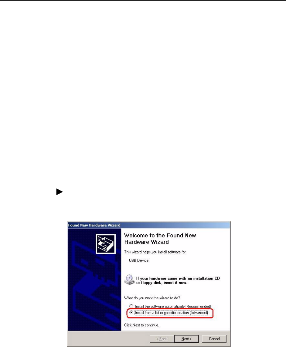
Windows USB Driver Installation
As soon as you connect the USB cable between your PC and the router, Windows
will detect new hardware and the Found New Hardware Wizard will pop up. To
install the USB driver:
Procedure
1. Choose "Install from a list or specific location" and click on Next (Figure 2-2).
Figure 2-2. Found New Hardware Wizard
2. Hardware Installation and PC Setup
2-4 January 2005 6381-A2-GB23-10
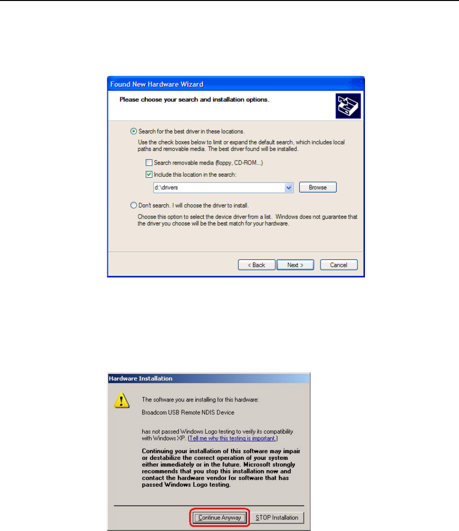
2. Insert the supplied CD and use Browse to include the location D:\drivers in the
search, where D: is the letter you use for your CD drive (Figure 2-3).
Figure 2-3. New Hardware Installation Options
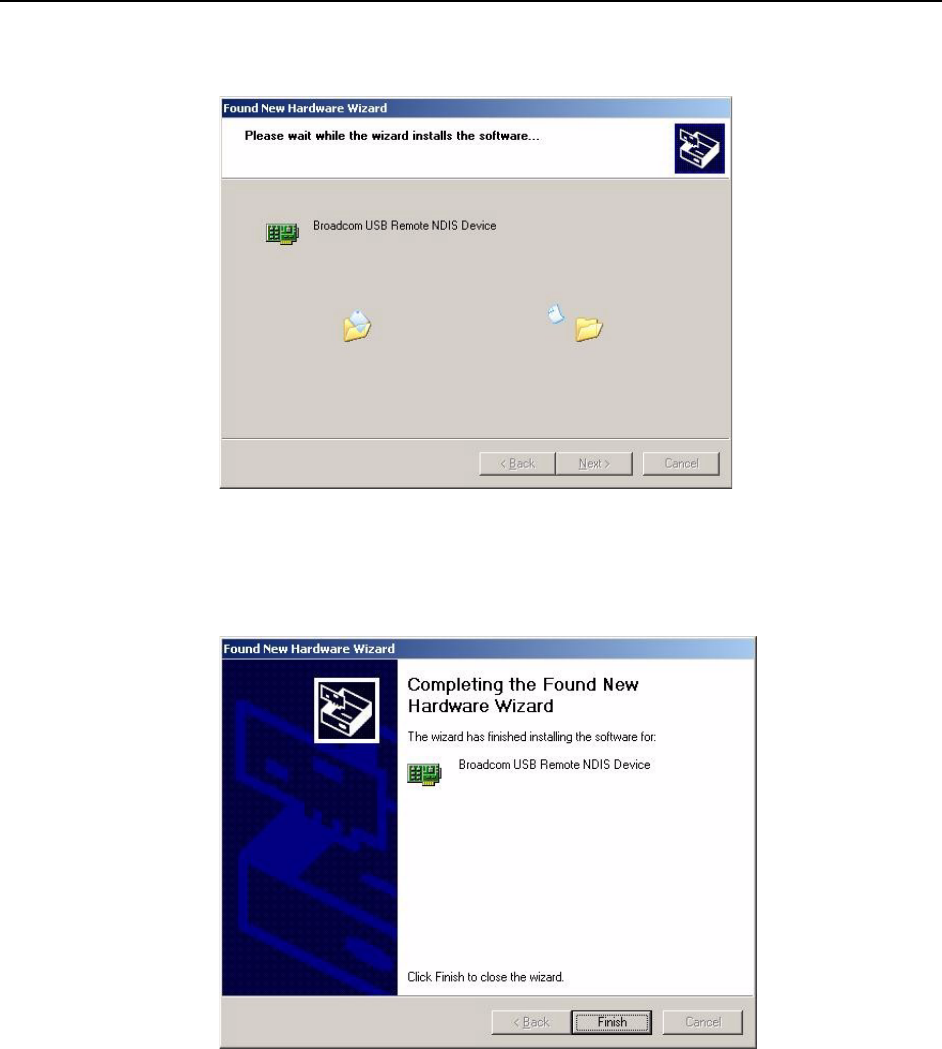
3. The Wizard will ask you to confirm the hardware installation. Choose Continue
Anyway. Windows will then install the supplied USB driver on your PC
(Figure 2-4 and Figure 2-5).
Figure 2-4. Hardware Installation Confirmation

2. Hardware Installation and PC Setup
2-6 January 2005 6381-A2-GB23-10
Configuring Your PC’s IP Address
Before you start to access the router using the Ethernet or USB connection, you
must configure your PC's TCP/IP address to be 192.168.1.x, where x is any
number between 2 and 254. The subnet mask is 255.255.255.0.
Your router's default IP address is 192.168.1.1.
Assigning an IP Address to your PC Automatically by DHCP
To use the router's DHCP feature, click in the radio button labeled “Obtain an IP
address automatically” instead of “Use the following IP address” in the following
procedures.
By default, the LAN port IP address of the router is 192.168.1.1. (You can change
this address, or another address can be assigned by your ISP.)
Windows XP
To configure the IP address under Windows XP:
Procedure
1. In the Windows task bar, click on the Start button, and then click on Control
Panel.
2. Double-click on the Network Connections icon.
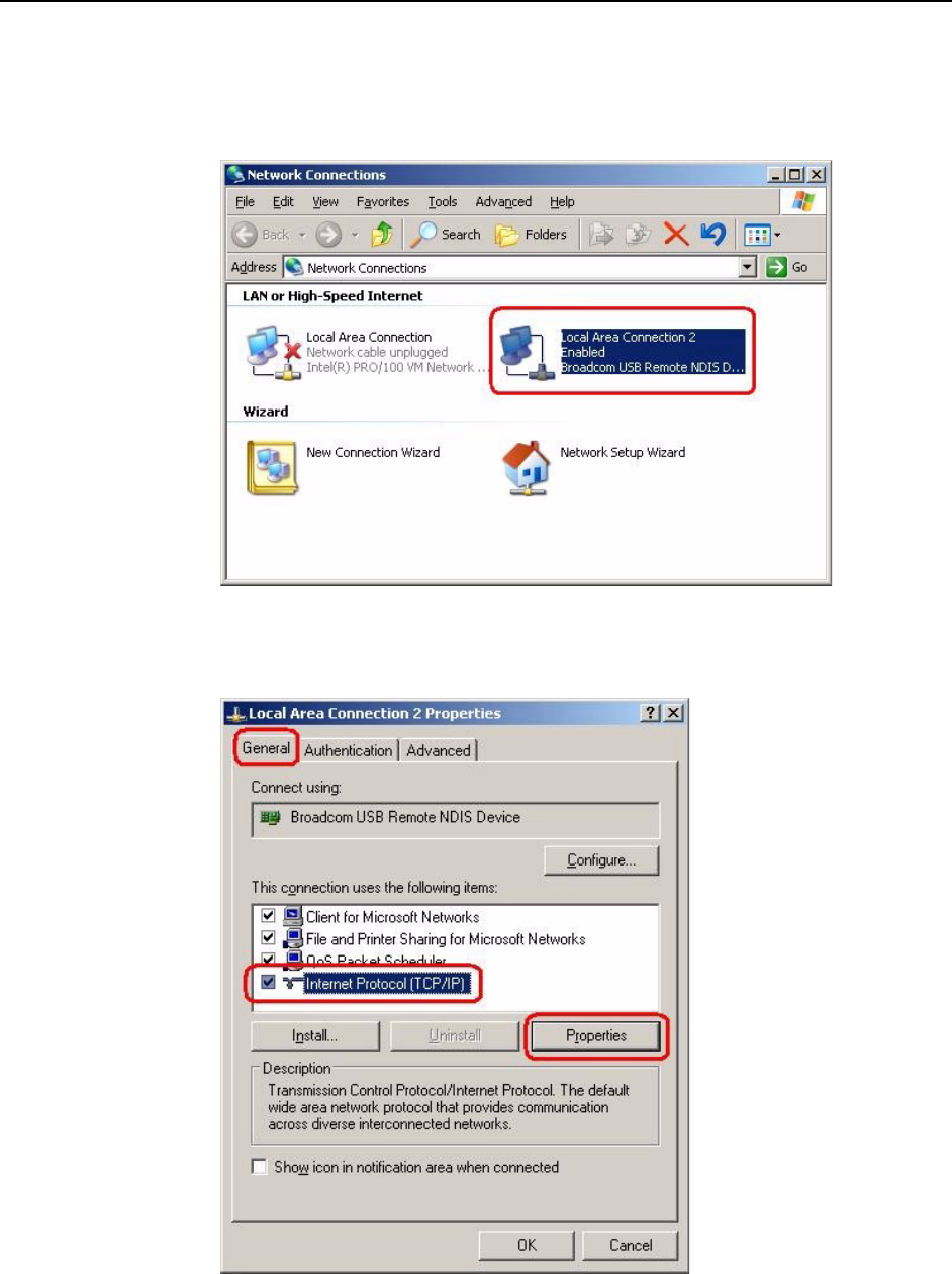
3. In the LAN or High-Speed Internet window, right-click on the icon
corresponding to your network interface card (NIC) and select Properties.
(Often this icon is labeled Local Area Connection). The Local Area Connection
dialog box is displayed with a list of currently installed network items.
2. Hardware Installation and PC Setup
6381-A2-GB23-10 January 2005 2-7
4. Ensure that the check box to the left of the item labeled Internet Protocol
(TCP/IP) is checked, and click on Properties.
Figure 2-7. Network Connections in Windows XP
Figure 2-8. Local Area Connection Properties in Windows XP

2. Hardware Installation and PC Setup
2-8 January 2005 6381-A2-GB23-10
5. In the Internet Protocol (TCP/IP) Properties dialog box, click in the radio button
labeled “Use the following IP address” and type 192.168.1.x (where x is any
number between 2 and 254) in the IP Address field. Type 255.255.255.0 in the
Subnet Mask field.
Figure 2-9. TCP/IP Properties in Windows XP
6. Click on OK twice to confirm your changes, and close the Control Panel.
Windows 2000
To configure the IP address under Windows 2000:
Procedure
1. In the Windows task bar, click on the Start button, point to Settings, and then
select Control Panel.
2. Double-click on the Network and Dial-up Connections icon.
3. In the Network and Dial-up Connections window, right-click on the Local Area
Connection icon, and then select Properties.
The Local Area Connection Properties dialog box is displayed with a list of
currently installed network components. If the list includes Internet Protocol
(TCP/IP), the protocol has already been enabled, in which case you can skip
to Step 10.

2. Hardware Installation and PC Setup
6381-A2-GB23-10 January 2005 2-9
4. If Internet Protocol (TCP/IP) does not appear as an installed component, click
on Install.
5. In the Select Network Component Type dialog box, select Protocol, and then
click on Add.
6. Select Internet Protocol (TCP/IP) in the Network Protocols list, and then click
on OK.
You may be prompted to install files from your Windows 2000 installation CD
or other media. Follow the instructions to install the files.
7. If prompted, click on OK to restart your computer with the new settings.
8. After restarting your PC, double-click on the Network and Dial-up Connections
icon in the Control Panel.
9. In Network and Dial-up Connections window, right-click on the Local Area
Connection icon, and then select Properties.
10. In the Local Area Connection Properties dialog box, select Internet Protocol
(TCP/IP), and then click on Properties.
11. In the Internet Protocol (TCP/IP) Properties dialog box, click in the radio button
labeled “Use the following IP address” and type 192.168.1.x (where x is any
number between 2 and 254) in the IP Address field. Type 255.255.255.0 in the
Subnet Mask field.
12. Click on OK twice to confirm and save your changes, and then close the
Control Panel.
Windows ME
To configure the IP address under Windows ME:
Procedure
1. In the Windows task bar, click on the Start button, point to Settings, and then
click on Control Panel.
2. Double-click on the Network and Dial-up Connections icon.
3. In the Network and Dial-up Connections window, right-click on the Network
icon, and then select Properties.
The Network Properties dialog box is displayed with a list of currently installed
network components. If the list includes Internet Protocol (TCP/IP), the
protocol has already been enabled, in which case you can skip to Step 11.
4. If Internet Protocol (TCP/IP) does not appear as an installed component, click
on Add.
5. In the Select Network Component Type dialog box, select Protocol, and then
click on Add.
6. Select Microsoft in the Manufacturers box.
7. Select Internet Protocol (TCP/IP) in the Network Protocols list, and then click
on OK.

2. Hardware Installation and PC Setup
2-10 January 2005 6381-A2-GB23-10
You may be prompted to install files from your Windows ME installation CD or
other media. Follow the instructions to install the files.
8. If prompted, click on OK to restart your computer with the new settings.
9. After restarting your PC, double-click on the Network and Dial-up Connections
icon in the Control Panel.
10. In Network and Dial-up Connections window, right-click on the Network icon,
and then select Properties.
11. In the Network Properties dialog box, select TCP/IP, and then click on
Properties.
12. In the TCP/IP Settings dialog box, click in the radio button labeled “Use the
following IP address” and type 192.168.1.x (where x is any number between 2
and 254) in the IP Address field. Type 255.255.255.0 in the Subnet Mask field.
13. Click on OK twice to confirm and save your changes, and then close the
Control Panel.
Windows 95, 98
To configure the IP address under Windows 95 or Windows 98:
Procedure
1. In the Windows task bar, click on the Start button, point to Settings, and then
click on Control Panel.
2. Double-click on the Network icon.
The Network dialog box is displayed with a list of currently installed network
components. If the list includes TCP/IP, the protocol has already been
enabled, in which case you can skip to Step 9.
3. If TCP/IP does not appear as an installed component, click on Add. The Select
Network Component Type dialog box appears.
4. Select Protocol, and then click on Add. The Select Network Protocol dialog
box appears.
5. Click on Microsoft in the Manufacturers list box, and then click on TCP/IP in
the Network Protocols list box.
6. Click on OK to return to the Network dialog box, and then click on OK again.
You may be prompted to install files from your Windows 95/98 installation CD.
Follow the instructions to install the files.
7. Click on OK to restart the PC and complete the TCP/IP installation.
8. After restarting your PC, open the Control Panel window, and then click on the
Network icon.
9. Select the network component labeled TCP/IP, and then click on Properties.
If you have multiple TCP/IP listings, select the listing associated with your
network card or adapter.

2. Hardware Installation and PC Setup
6381-A2-GB23-10 January 2005 2-11
10. In the TCP/IP Properties dialog box, click on the IP Address tab.
11. Click in the radio button labeled “Use the following IP address” and type
192.168.1.x (where x is any number between 2 and 254) in the IP Address
field. Type 255.255.255.0 in the Subnet Mask field.
12. Click on OK twice to confirm and save your changes. You will be prompted to
restart Windows. Click on Yes and restart your PC again.
Windows NT 4.0
To configure the IP address under Windows NT 4.0:
Procedure
1. In the Windows NT task bar, click on the Start button, point to Settings, and
then click on Control Panel.
2. In the Control Panel window, double click on the Network icon.
3. In the Network dialog box, click on the Protocols tab.
The Protocols tab displays a list of currently installed network protocols. If the
list includes TCP/IP, the protocol has already been enabled, in which case you
can skip to Step 9.
4. If TCP/IP does not appear as an installed component, click on Add.
5. In the Select Network Protocol dialog box, select TCP/IP, and then click on
OK.
You may be prompted to install files from your Windows NT installation CD or
other media. Follow the instructions to install the files.
After all files are installed, a window displays to inform you that a TCP/IP
service called DHCP can be set up to dynamically assign IP information.
6. Click on Yes to continue, and then click on OK if prompted to restart your
computer.
7. After restarting your PC, open the Control Panel window, and then double-click
on the Network icon.
8. In the Network dialog box, click on the Protocols tab.
9. In the Protocols tab, select TCP/IP, and then click on Properties.
10. In the Microsoft TCP/IP Properties dialog box, click in the radio button labeled
Use the following IP address and type 192.168.1.x (where x is any number
between 2 and 254) in the IP Address field. Type 255.255.255.0 in the Subnet
Mask field.
11. Click on OK twice to confirm and save your changes, and then close the
Control Panel.

2. Hardware Installation and PC Setup
2-12 January 2005 6381-A2-GB23-10
6381-A2-GB23-10 January 2005 3-1
3
Using the Web Interface
Logging Into Your Router
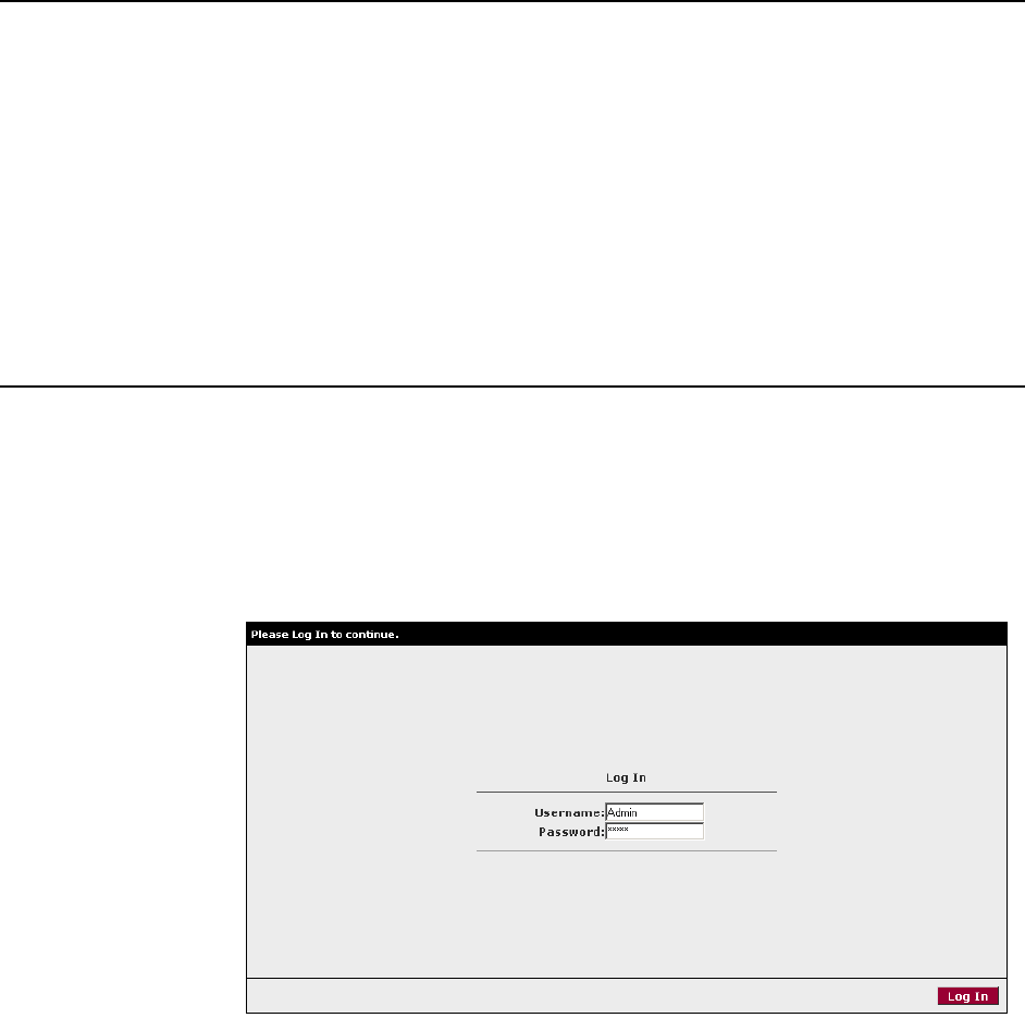
To configure your router, open your web browser. Ignore any error about lacking a
connection. Type the default IP address (192.168.1.1) into the Location field of
your browser and press the Enter key. The following screen appears.
Figure 3-1. Login Screen
The default user name is Admin and the password is Admin. Both are
case-sensitive.
Note: Before configuring your router, make sure you have followed the instructions
in Chapter 2, Hardware Installation and PC Setup. You should have your PCs
configured for DHCP mode (if your router will be), and have proxies disabled on
your browser. If you see a login redirection screen when you access the web
interface, verify that JavaScript support is enabled in your browser. Also, if you do
not get the screen shown in Figure 3-1, you may need to delete your temporary
Internet files.
3. Using the Web Interface
3-2 January 2005 6381-A2-GB23-10
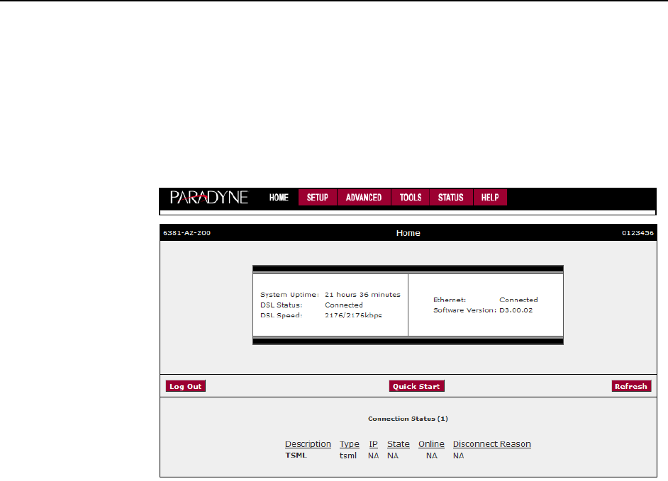
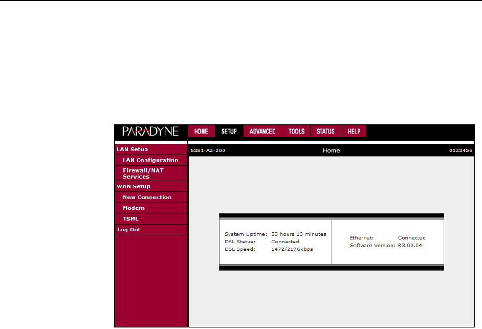
Home Page
The first screen (Figure 3-2) that appears after the log in screen is the Home page.
From this screen you can configure the LAN and WAN connections, configure the
router's security, routing, and filtering, access debugging tools, obtain the status of
the router, and view the online help.
Figure 3-2. Home Page
The footer displays router status, connection information, and other useful
information.
Click on Log Out to close the session, Refresh to update the status display, or
Quick Start to configure basic options.
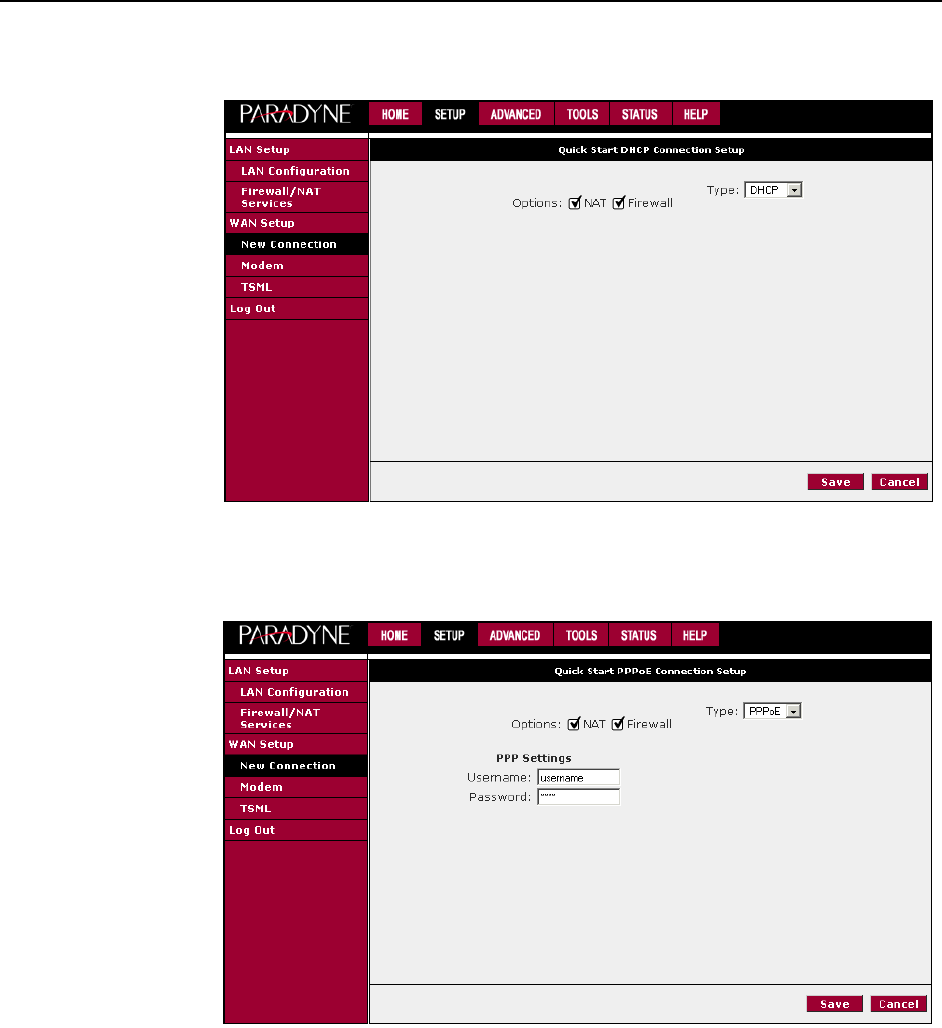
Quick Start
The Quick Start screen gives you immediate access to the options you are most
likely to need to specify or change. Click on the Quick Start button on the Home
page to access it.
Select a connection type from the drop-down list:
DHCP – The address of the router is automatically assigned
PPPoE – Your service provider has restricted access by name and password
Static – Your service provider has supplied a specific network address for your
router
3. Using the Web Interface
6381-A2-GB23-10 January 2005 3-3
Figure 3-3. Quick Start - DHCP
Figure 3-4. Quick Start - PPPoE
3. Using the Web Interface
3-4 January 2005 6381-A2-GB23-10
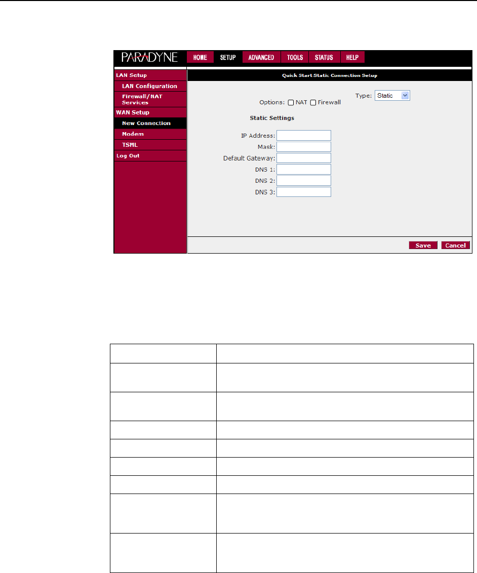
Figure 3-5. Quick Start - Static
Enter or select Quick Start options as shown in the following table.
Click on Save to make the changes permanent.
Table 3-1. Quick Start Options
Field Description
NAT Click in the check box to activate Network Address Translation
(NAT). See Appendix A, Te r m i n o l o gy , for a description of NAT.
Firewall Click in the check box to activate the firewall. See Appendix A,
Terminology, for a description of a firewall.
Username (PPPoE) Enter the user name given to you by your service provider.
Password (PPPoE) Enter the password given to you by your service provider.
IP Address (Static) Enter the IP address to be assigned to the router.
Mask (Static) Enter the subnet mask to be applied to the IP address.
Default Gateway (Static) Enter the IP address of a default gateway. Packets for which
the router has no appropriate route are sent to the default
gateway.
DNS 1–3 (Static) Enter the IP address of the primary domain name server, and
optionally the addresses of a secondary and tertiary DNS to
be used if the server before it is unavailable.
3. Using the Web Interface
6381-A2-GB23-10 January 2005 3-5
Setup
To set up options not available on the Quick Start screen, select Setup from the
Home page. Figure 3-6 shows the Setup page. The menu has two sections: the
WAN configuration and the LAN configuration.
Figure 3-6. Setup Options
Wide Area Network Connection
The DSL connection is the Wide Area Network (WAN) connection. The
requirements for the WAN connection depend on your Internet Service Provider
(ISP).
Local Area Network Connection
On the other side of your router are your own Local Area Network (LAN)
connections. This is where you plug in your local computers to the router. The
router is normally configured to automatically provide all the PCs on your network
with Internet addresses.
If you connected a PC (rather than a hub or a switch) directly to the router, your
LAN consists of that PC.
Saving Changes
Note that the Apply button temporarily saves changes you make. To make
changes permanent, click on Tools (at the top of the page) and select System
Commands. At the System Commands page, click on Save All.

3. Using the Web Interface
3-6 January 2005 6381-A2-GB23-10
Configuring the WAN
Before the router will pass any data between the LAN interface and the WAN
interface, the WAN side of the router must be configured. Depending upon your
ISP, you will need some or all of the information listed below before you can
properly configure the WAN:
Your DSL line’s Virtual Path Identifier (VPI) and Virtual Channel Identifier (VCI)
Your DSL encapsulation type and multiplexing mode
Your DSL training mode (default is MMODE)
If you use PPPoA or PPPoE, you also need these values from your ISP:
Your username and password
If you use multiprotocol encapsulation over ATM Adaptation Layer 5 (as described
in RFC 1483), you may need these values from your ISP:
Your DSL fixed Internet IP address
Your subnet mask
Your default gateway IP address
Your primary DNS IP address
Since multiple users can use the router, the router can simultaneously support
multiple connection types. You must set up different profiles for each connection.
The router supports the following protocols:
DHCP
PPPoA (RFC 2364)
PPPoE (RFC 2516)
Static
Bridged

3. Using the Web Interface
6381-A2-GB23-10 January 2005 3-7
New Connection
A new connection is basically a virtual connection. Your router can support up to 8
different virtual connections. If you have multiple different virtual connections, you
may need to utilize the static and dynamic routing capabilities of the router to pass
data correctly.
PPPoE Connection Setup
PPPoE is defined in the Internet standard RFC 2516. It is a method of
encapsulating PPP packets over Ethernet. PPP (Point-to-Point Protocol) is a
method of establishing a network session between network hosts. It usually
provides a mechanism of authenticating users.
To configure the router for PPPoE:
Procedure
1. Click on Setup and then click on New Connection. The default PPPoE
connection setup is displayed.
2. At the Type field, select PPPoE and the PPPoE Connection Setup page is
displayed.
3. Give your PPPoE connection a unique name. The name must not have spaces
and cannot begin with numbers.
4. Select a PVC Sharing type of Disable, Enable, or VLAN.
5. Select or enter a VPI and VCI (as supplied by your DSL service provider or
your ISP), or click in Auto PVC. (Auto PVC causes the router to perform
automatic VPI/VCI detection as defined in DSL forum TR-068.) For VLAN,
specify a VLAN ID and priority.
6. Select NAT and Firewall if you want them active for this connection. Firewall
and NAT services must be enabled. See Firewall/NAT Services on page 3-21.
7. Select the quality of service (QOS). Leave the default value if your ISP did not
provide this information. Depending on the QoS you select, you may also
enter:
— PCR (Peak Cell Rate)
— SCR (Sustainable Cell Rate)
— MBS (Maximum Burst Size)
— CDVT (Cell Delay Variation Tolerance)
Following is a description of the different options:
Username - The username for the PPPoE access. This is provided by your
DSL service provider or your ISP.
Password - The password for the PPPoE access. This is provided by your DSL
service provider or your ISP.

3. Using the Web Interface
3-8 January 2005 6381-A2-GB23-10
Idle Timeout - Specifies that PPPoE connection should disconnect if the link
has no activity detected for the specified number of seconds. This field is used
in conjunction with the On Demand feature. To disable the timeout feature,
enter a zero in this field.
Authentication – Specifies the authentication protocol: Auto (the protocol is
selected by the Central Office modem), PAP (Password Authentication
Protocol), or CHAP (Challenge Handshake Authentication Protocol).
Keep Alive - When the On Demand option is not enabled, this value specifies
the length of time to keep the connection from being shut down for inactivity by
sending PPP LCP echoes to the PPP server. To ensure that the link is always
active, enter a zero in this field.
MTU - The Maximum Transmission Unit the DSL connection can send. It is a
negotiated value. The maximum specified value is 1500, although some
DSL/ISP providers require a larger value. The minimum MTU value is 128.
On Demand - Enables on-demand mode. The connection will disconnect if no
activity is detected after the specified idle timeout value.
Default Gateway – Specifies whether a default gateway is used.
Enforce MTU - Check this box if you experience problems accessing the
Internet over a PPPoE connection. This feature will force all TCP traffic to
conform with PPP MTU by changing TCP Maximum Segment Size to the PPP
MTU.
Debug - Enables PPPoE connection debugging facilities. See Remote Log on
page 3-36.
PPP Unnumbered – Specifies that the calling and answering routers will not
request IP addresses.
Figure 3-7. PPPoE Connection Setup

3. Using the Web Interface
6381-A2-GB23-10 January 2005 3-9
To complete the connection you must now click the Apply button. The Apply button
will temporarily save this connection. To make the change permanent, click on
Tools (at the top of the page) and select System Commands. At the System
Commands page, click on Save All.
PPPoA Connection Setup
PPPoA is defined in the Internet standard RFC 2364. It is a method of
encapsulating PPP packets over ATM cells which are carried over the DSL line.
PPP (Point-to-Point Protocol) is a method of establishing a network session
between network hosts. It usually provides a mechanism of authenticating users.
LLC and VC are two different methods of encapsulating the PPP packet. Contact
your ISP to make sure which encapsulation is being supported.
By selecting PPPoA, you are forcing your router to act as the termination point for
the PPPoA connection. This frees up your PC resources and allows multiple users
to utilize the PPPoA connection.
To configure the router for PPPoA:
Procedure
1. Click on Setup and then click on New Connection. The default PPPoE
connection setup is displayed.
2. At the Type field select PPPoA and the PPPoA connection setup page is
displayed.
3. Give your PPPoA connection a unique name. The name must not have spaces
and cannot begin with numbers.
4. Select or enter a VPI and VCI (as supplied by your DSL service provider or
your ISP), or click in Auto PVC. (Auto PVC causes the router to perform
automatic VPI/VCI detection as defined in DSL forum TR-068.) For VLAN,
specify a VLAN ID and priority.
5. Select NAT and Firewall if you want them active for this connection. Firewall
and NAT services must be enabled. See Firewall/NAT Services on page 3-21.
6. Select the encapsulation type (LLC or VC); if you are not sure just use the
default mode.
7. Select the quality of service (QOS). Leave the default value if your ISP did not
provide this information. Depending on the QoS you select, you may also
enter:
— PCR (Peak Cell Rate)
— SCR (Sustainable Cell Rate)
— MBS (Maximum Burst Size)
— CDVT (Cell Delay Variation Tolerance)
Following is a description of the different options:

3. Using the Web Interface
3-10 January 2005 6381-A2-GB23-10
Username – The username for the PPPoA access. This is provided by your
DSL service provider or your ISP.
Password – The password for the PPPoA access. This is provided by your
DSL service provider or your ISP.
Idle Timeout – Specifies that PPPoA connection should disconnect if the link
has no activity detected for the specified number of seconds. This field is used
in conjunction with the On Demand feature. To disable the timeout feature,
enter a zero in this field.
Authentication – Specifies the authentication protocol: Auto (the protocol is
selected by the Central Office modem), PAP (Password Authentication
Protocol), or CHAP (Challenge Handshake Authentication Protocol).
Keep Alive – When the On Demand option is not enabled, this value specifies
the length of time to keep the connection from being shut down for inactivity by
sending PPP LCP echoes to the PPP server. To ensure that the link is always
active, enter a zero in this field.
MTU – The Maximum Transmission Unit the DSL connection can send. It is a
negotiated value. The maximum specified value is 1500, although some
DSL/ISP providers require a larger value. The minimum MTU value is 128.
On Demand – Enables on-demand mode. The connection will disconnect if no
activity is detected after the specified idle timeout value.
Default Gateway – Specifies whether a default gateway is used.
Debug – Enables PPPoA connection debugging facilities. See Remote Log on
page 3-36.
PPP Unnumbered – Specifies that the calling and answering routers will not
request IP addresses.
Figure 3-8. PPPoA Connection Setup

3. Using the Web Interface
6381-A2-GB23-10 January 2005 3-11
To complete the connection you must now click the Apply button. The Apply button
will temporarily save this connection. To make the change permanent, click on
Tools (at the top of the page) and select System Commands. At the System
Commands page, click on Save All.
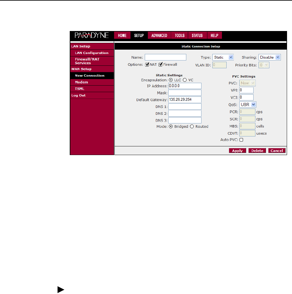
Static Connection Setup
A static connection is used whenever a known static IP is assigned. The
accompanying information such as the subnet mask and the default gateway
should also be specified. Up to three Domain Name Server (DNS) addresses can
also be specified. These servers give you access to other web servers. The valid
IP addresses range is 1.0.0.0 to 223.255.255.254.
To configure the router for a Static connection:
Procedure
1. Click on Setup and then click on New Connection. The default Static
connection setup is displayed.
2. At the Type field select Static. The Static Connection Setup page is displayed.
3. Give your Static connection a unique name. The name must not have spaces
and cannot begin with numbers.
4. Optionally enable Network Address Translation (NAT) and the Firewall options.
Firewall and NAT services must be enabled. See Firewall/NAT Services on
page 3-21.
5. Select a PVC Sharing type of Disable, Enable, or VLAN.
6. Select or enter a VPI and VCI (as supplied by your DSL service provider or
your ISP), or click in Auto PVC. (Auto PVC causes the router to perform
automatic VPI/VCI detection as defined in DSL forum TR-068.) For VLAN,
specify a VLAN ID and priority.
7. Select the encapsulation type (LLC or VC). If you are not sure which to use,
just use the default mode.
8. Based upon the information your ISP provided, enter your assigned IP
Address, Subnet Mask, Default Gateway (if provided), and Domain Name
Services (DNS) address (if provided). Specify the VPI and VCI settings. Your
DSL service provider or your ISP will supply these.
9. Select the quality of service (QOS). Leave the default value if your ISP did not
provide this information.
10. Set the mode to Bridged or Routed as instructed by your ISP.
3. Using the Web Interface
3-12 January 2005 6381-A2-GB23-10
Figure 3-9. Static IP Connection Setup
To complete the connection you must now click the Apply button. The Apply button
will temporarily save this connection. To make the change permanent, click on
Tools (at the top of the page) and select System Commands. At the System
Commands page, click on Save All.
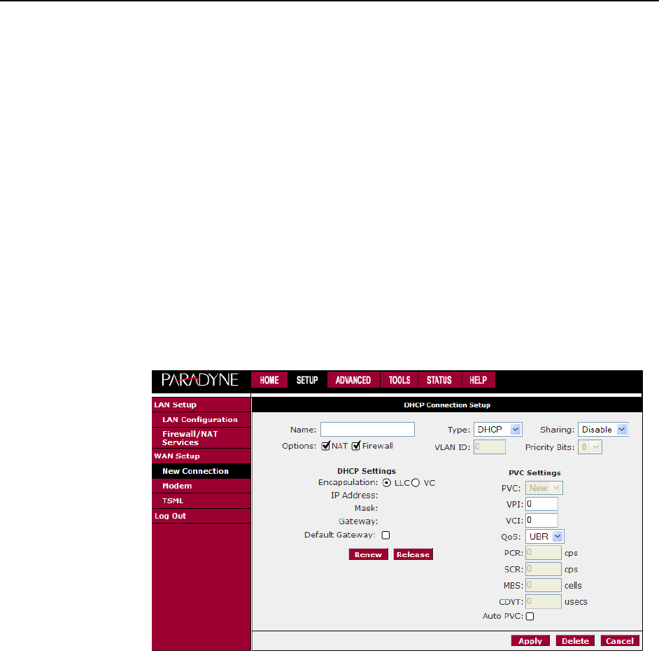
DHCP Connection Setup
Dynamic Host Configuration Protocol (DHCP) allows the router to automatically
obtain the IP address from the server. This option is commonly used in situations
where IP is dynamically assigned and is not known prior to assignment.
To configure the router for a DHCP connection:
Procedure
1. Click on Setup and then click on New Connection. The default PPPoE
connection setup is displayed.
2. At the Type field select DHCP and the DHCP connection setup page is
displayed.
3. Give your DHCP connection a unique name. The name must not have spaces
and cannot begin with numbers.
4. Select a PVC Sharing type of Disable, Enable, or VLAN.
5. Select or enter a VPI and VCI (as supplied by your DSL service provider or
your ISP), or click in Auto PVC. (Auto PVC causes the router to perform
automatic VPI/VCI detection as defined in DSL forum TR-068.) For VLAN,
specify a VLAN ID and priority.
6. Select NAT and Firewall if you want them active for this connection. Firewall
and NAT services must be enabled. See Firewall/NAT Services on page 3-21.
3. Using the Web Interface
6381-A2-GB23-10 January 2005 3-13
7. Select the encapsulation type (LLC or VC). If you are not sure which to use,
just use the default mode.
8. Select the quality of service (QOS). Leave the default value if your ISP did not
provide this information. Depending on the QoS you select, you may also
enter:
— PCR (Peak Cell Rate)
— SCR (Sustainable Cell Rate)
— MBS (Maximum Burst Size)
— CDVT (Cell Delay Variation Tolerance)
If your DSL line is connected and your DSL provider is supporting DHCP, you can
click on the Renew button and the router will retrieve an IP Address, Subnet Mask,
and Default Gateway address. At any time you can renew the DHCP address by
clicking on the Renew button.
Figure 3-10. DHCP Connection Setup
To complete the connection you must now click the Apply button. The Apply button
will temporarily save this connection. To make the change permanent, click on
Tools (at the top of the page) and select System Commands. At the System
Commands page, click on Save All.
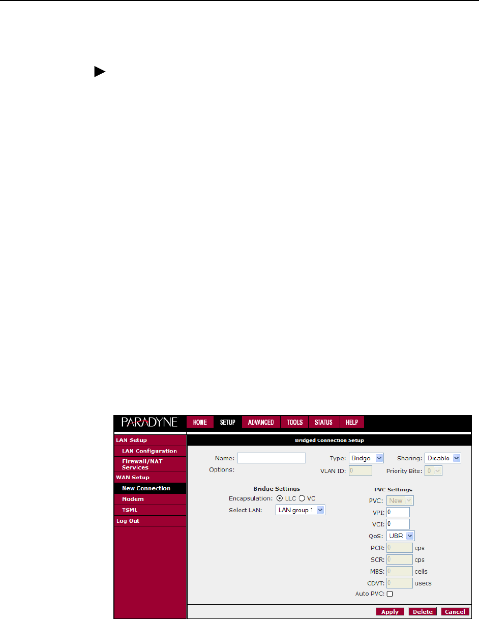
Bridged Connection
A pure bridged connection does not assign an IP address to the WAN interface.
This connection method makes the router act as a hub that passes packets across
the WAN interface to the LAN interface.
3. Using the Web Interface
3-14 January 2005 6381-A2-GB23-10
To configure the router as a bridge:
Procedure
1. From the Home page, click on Setup and then click on New Connection. The
default PPPoE connection setup is displayed.
2. At the Type field select Bridge and the Bridge connection setup page is
displayed (see Figure 3-11).
3. Give your Bridge connection a unique name; the name must not have spaces
and cannot begin with numbers.
4. Select a PVC Sharing type of Disable, Enable, or VLAN.
5. For a Sharing type of Enable or VLAN, select or enter a VPI and VCI. (Your
DSL service provider or your ISP will supply these.) For VLAN, specify a VLAN
ID and priority.
6. Select the encapsulation type (LLC or VC); if you are not sure which to use,
just use the default mode.
7. Select the quality of service (QoS). Leave the default value if you are unsure
or the ISP did not provide this information. Depending on the QoS you select,
you may also enter:
— PCR (Peak Cell Rate)
— SCR (Sustainable Cell Rate)
— MBS (Maximum Burst Size)
— CDVT (Cell Delay Variation Tolerance)
Figure 3-11. Bridged Connection Setup
To complete the connection you must now click the Apply button. The Apply button
will temporarily save this connection. To make the change permanent, click on

3. Using the Web Interface
6381-A2-GB23-10 January 2005 3-15
Tools (at the top of the page) and select System Commands. At the System
Commands page, click on Save All.
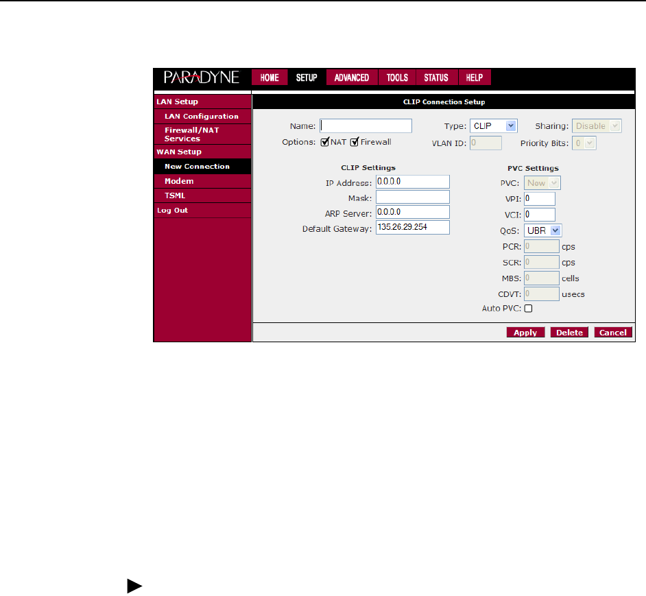
CLIP Connection
Classical IP and ARP over ATM (CLIP) allows IP datagrams and ARP (Address
Resolution Protocol) requests and replies to be transmitted over ATM using ATM
Adaptation Layer 5 (AAL5).
To configure a CLIP connection:
Procedure
1. From the Home page, click on Setup and then click on New Connection. The
default PPPoE connection setup is displayed.
2. At the Type field select CLIP and the CLIP connection setup page is displayed.
3. Give your CLIP connection a unique name; the name must not have spaces
and cannot begin with numbers.
4. Select NAT and Firewall if you want them active for this connection. Firewall
and NAT services must be enabled. See Firewall/NAT Services on page 3-21.
5. Select or enter a VPI and VCI (as supplied by your DSL service provider or
your ISP), or click in Auto PVC. (Auto PVC causes the router to perform
automatic VPI/VCI detection as defined in DSL forum TR-068.)
6. Specify the IP address and subnet mask.
7. Specify the address of the ARP server.
8. Specify the address of the Default Gateway.
9. Select the quality of service (QoS). Leave the default value if you are unsure
or the ISP did not provide this information. Depending on the QoS you select,
you may also enter:
— PCR (Peak Cell Rate)
— SCR (Sustainable Cell Rate)
— MBS (Maximum Burst Size)
— CDVT (Cell Delay Variation Tolerance)
3. Using the Web Interface
3-16 January 2005 6381-A2-GB23-10
Figure 3-12. CLIP Connection Setup
To complete the connection you must now click the Apply button. The Apply button
will temporarily save this connection. To make the change permanent, click on
Tools (at the top of the page) and select System Commands. At the System
Commands page, click on Save All.
Modify an Existing Connection
To modify an existing connection:
Procedure
1. From the Home screen, click on Setup.
2. Click on the connection you want to modify. The connections are listed by
name.
If you delete a connection, to make the change permanent, click on Tools (at the
top of the page) and select System Commands. At the System Commands page,
click on Save All.
3. Using the Web Interface
6381-A2-GB23-10 January 2005 3-17
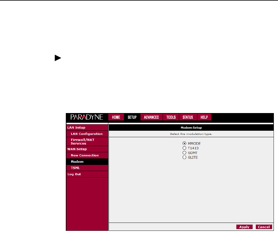
Modem Setup
To configure the DSL modulation type:
Procedure
1. From the Home screen, click on Setup.
2. Under WAN Setup, select Modem Setup. This will bring up the Modem Setup
screen. Leave the default value if your ISP did not provide this information.
For most cases, this screen should not be modified.
Figure 3-13. Modem Setup
The Apply button will temporarily save these settings. To make the change
permanent, click on Tools (at the top of the page) and select System Commands.
At the System Commands page, click on Save All.
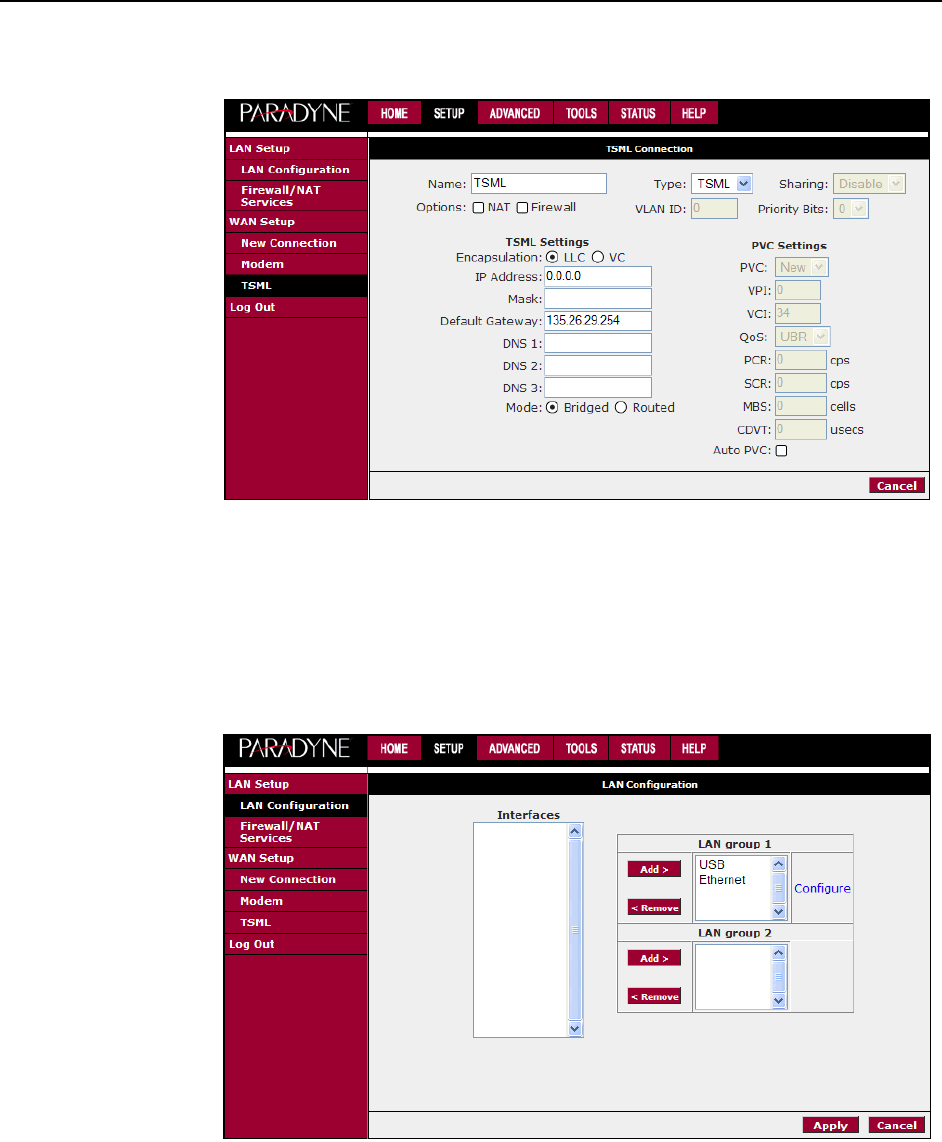
TSML
Troubleshooting Management Link (TSML) is a feature that lets authorized
Network Operations Center (NOC) personnel troubleshoot and manage the router
from the NOC.
The TSML connection (VPI 0, VCI 34) examines incoming packets, looking for
ICMP Echo Requests. If the TSML connection receives five ICMP Echo Request
packets with the same destination IP address within five seconds, it adopts the
destination IP address. The address can then be used to access the router. No
authentication is required over the link.
The TSML connection is automatically configured. The TSML Connection screen
shows the settings, but they cannot be altered and saved.
3. Using the Web Interface
3-18 January 2005 6381-A2-GB23-10
Figure 3-14. TSML Connection
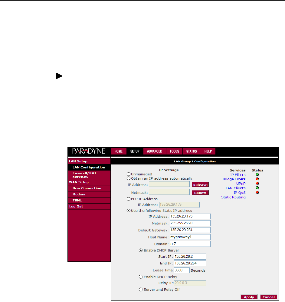
Configuring the LAN
To configure LAN parameters, click on Setup on the Home screen. Under LAN
Setup, click on LAN Configuration. The LAN Configuration screen appears.
Figure 3-15. LAN Configuration Screen
By default, both the Ethernet port and USB port are in LAN Group 1. The USB port
may be removed from LAN Group 1 and added to LAN Group 2 for separate
configuration.
3. Using the Web Interface
6381-A2-GB23-10 January 2005 3-19
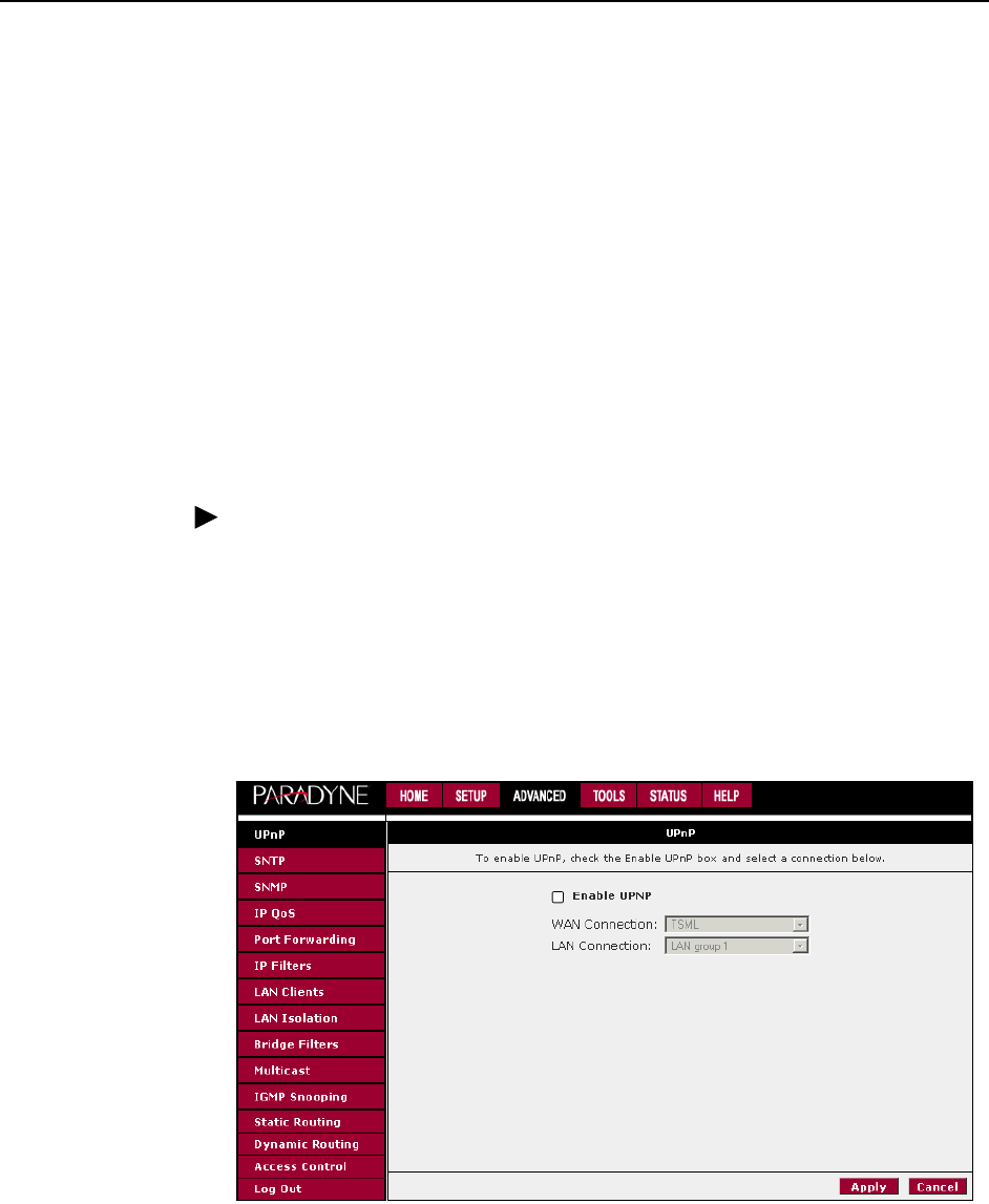
Enable/Disable DHCP
By default, the router has DHCP server (LAN side) disabled. If you already have a
DHCP server running on your network, do not enable the router’s DHCP server.
To enable or disable DHCP:
Procedure
1. From the Home screen, click on Setup.
2. Under LAN Setup, select LAN Configuration. This will bring up the screen
shown in Figure 3-15, LAN Configuration Screen.
3. Click on the Configure link in the LAN Group 1 window. The LAN Group 1
Configuration screen appears.
Figure 3-16. LAN Group 1 Configuration
4. The DHCP server is enabled when “Enable DHCP Server” is selected. If you
enable it:
— Specify a Start IP address. The Start IP Address is where the DHCP
server starts issuing IP addresses. This value must be greater than the
router's IP address value. For example, if the router's IP address is
192.168.1.1 (the default) than the Start IP address must be 192.168.1. 2
or higher.
— Specify an End IP address. The End IP Address is the last address the
DHCP server can issue. The ending address cannot exceed a subnet limit
of 254. The maximum IP address for a router using the default address is

3. Using the Web Interface
3-20 January 2005 6381-A2-GB23-10
192.168.1.254. If the DHCP server runs out of DHCP addresses, users
will not get access to network resources.
— Specify a Lease Time. The Lease Time is the amount of time a network
user will be allowed connection to the Router with their current dynamic IP
address. The amount of time is in units of seconds; the default value is
3600 seconds (1 hour).
Note: If you change the start or end values, make sure the values are still within
the same subnet as the router's IP address. For example, if the router's IP address
is 192.168.1.1 (the default), and you change the DHCP Start and End IP
addresses to be 192.128.1.2 and 192.128.1.100, you will not be able to
communicate with the router if your PC has DHCP enabled.
In addition to the DHCP server feature, the router supports the DHCP relay
function. When the router is configured as DHCP server, it assigns the IP
addresses to the LAN clients. When the router is configured as DHCP relay, it is
responsible for forwarding the requests and responses negotiating between the
DHCP clients and the server.
If the DHCP server and relay are turned off, you must configure the IP address,
subnet mask and DNS settings of every computer on your network. Do not assign
the same IP address to more than one computer. Your router must be on the same
subnet as the computers.
The Apply button will temporarily save these settings. To make the change
permanent, click on Tools (at the top of the page) and select System Commands.
At the System Commands page, click on Save All.
Changing the Router's IP address
Your router's default IP address and subnet mask are 192.168.1.1 and
255.255.255.0, respectively. This subnet mask allows the router to support 254
users. Since the DHCP server issues a maximum of 255 addresses, there is not
much advantage to changing the subnet mask to increase the number of
addresses. Further, remember that if you change your router’s IP address and you
have DHCP enabled, the DHCP configuration must reside within the same subnet.
The default gateway is the routing device used to forward all traffic that is not
addressed to a station within the local subnet. Your ISP will provide you with the
default gateway address.
The Hostname can be any alphanumeric word beginning with a letter and
containing no spaces. The domain name is used to in conjunction with the host
name to uniquely identify the router.
To change the router's IP address:
Procedure
1. From the Home screen, click on Setup.
2. Under LAN Setup, select LAN Configuration. This will bring up the screen
shown in Figure 3-15, LAN Configuration Screen.

3. Using the Web Interface
6381-A2-GB23-10 January 2005 3-21
3. Click on the Configuration link in the LAN Group 1 window. The LAN Group 1
Configuration screen appears, as shown in Figure 3-16, LAN Group 1
Configuration.
4. Click on “Use the following Static IP Address”.
5. Enter a new IP Address and Netmask.
The Apply button will temporarily save these settings. To make the change
permanent, click on Tools (at the top of the page) and select System Commands.
At the System Commands page, click on Save All.
Firewall/NAT Services
To enable or disable Firewall and NAT:
Procedure
1. From the Home screen, click Setup.
2. Under LAN Setup, select Firewall/NAT Services. By unselecting the Enable
Firewall and NAT Services button the firewall and NAT services is disabled for
all WAN connections. Enabling Firewall NAT does not automatically apply it to
connections.
The Apply button will temporarily save this setting. To make the change
permanent, click on Tools (at the top of the page) and select System Commands.
At the System Commands page, click on Save All.
Figure 3-17. Firewall/NAT Services Screen
3. Using the Web Interface
3-22 January 2005 6381-A2-GB23-10
Advanced
The router supports a host of advanced features. For basic router functionality, you
do not need to utilize these advanced features. The features help with routing,
security, port configuration, and plug and play capability.
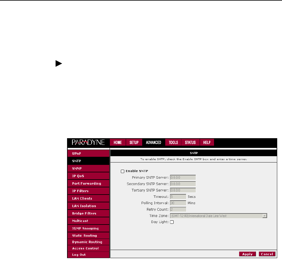
UPnP
UPnP NAT and Firewall Traversal allow traffic to pass through the router for
applications using the UPnP protocol. This feature requires one active DSL
connection. In the presence of multiple DSL connections, select the one over
which the incoming traffic will be present, such as the default Internet connection.
To enable UPnP you must first have a WAN connection configured. Once a WAN
connection is configured:
Procedure
1. From the Home screen, click on Advanced and under Advanced, select UPnP.
The UPnP screen appears.
2. Enable UPnP and then select which connection will utilize UPnP.
3. The Apply button will temporarily save these settings. To make the change
permanent, click on Tools and select System Commands. On the System
Commands page, click on Save All.
Figure 3-18. UPnP
3. Using the Web Interface
6381-A2-GB23-10 January 2005 3-23
SNTP
The SNTP screen lets you specify parameters related to SNTP (Simple Network
Time Protocol) servers. To use SNTP:
Procedure
1. From the Home screen, click on Advanced and under Advanced, select SNTP.
The SNTP screen appears.
2. Enable SNTP and then specify one or more SNTP servers.
3. The Apply button will temporarily save these settings. To make the change
permanent, click on Tools and select System Commands. On the System
Commands page, click on Save All.
Figure 3-19. SNTP
3. Using the Web Interface
3-24 January 2005 6381-A2-GB23-10
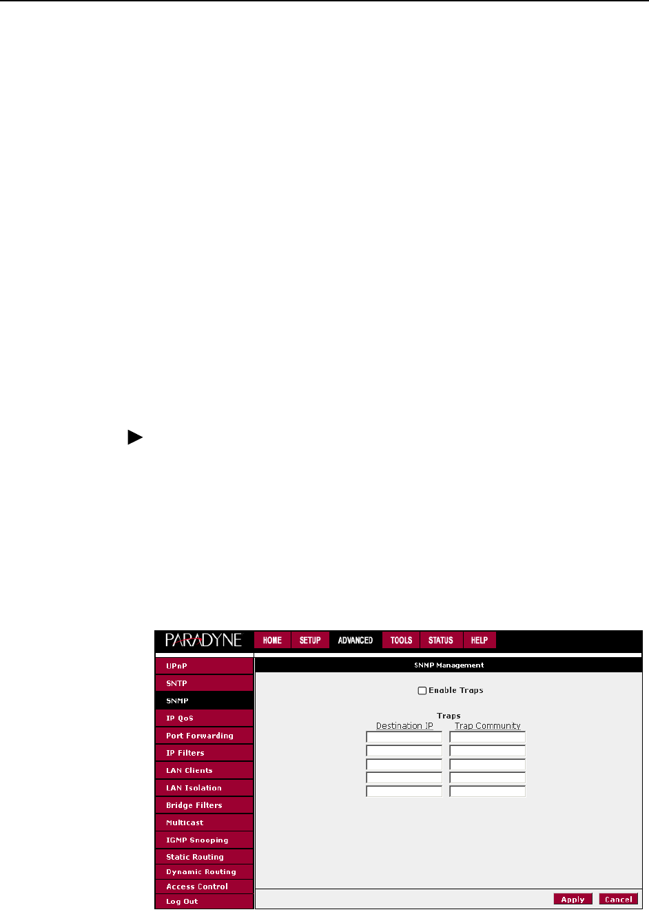
SNMP
Use the SNMP (Simple Network Management Protocol) screen to enable and
configure the SNMP agent and SNMP trap managers.
The SNMP feature generates a trap whenever the IP address of the router
changes (except through the Troubleshooting Management Link). The trap sent
contains the following:
Community (the community name configured for the trap destination, or
“public” if no community name was configured)
sysObjectID for the router
IP address of the agent sending the trap
Time stamp (sysUpTime)
Serial Number of the router
IP address of the router
Interface name
To configure SNMP:
Procedure
1. From the Home screen, click on Advanced and under Advanced, select SNMP.
The SNMP screen appears.
2. Enable the SNMP traps, then enter up to five Destination IP Addresses and
Community names.
The Apply button will temporarily save these settings. To make the change
permanent, click on Tools and select System Commands. On the System
Commands page, click on Save All.
Figure 3-20. SNMP
3. Using the Web Interface
6381-A2-GB23-10 January 2005 3-25
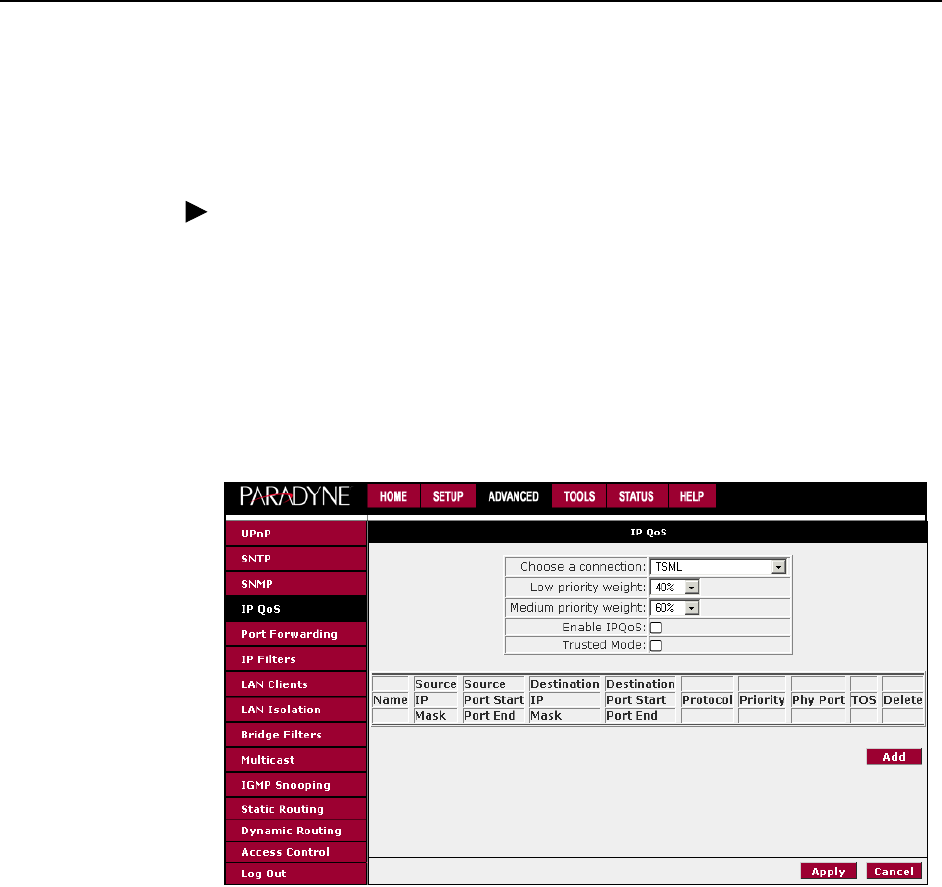
IP QoS
The IP QoS screen lets you establish a particular level of service for each
connection you have defined. To set QoS for a connection:
Procedure
1. From the Home screen, click on Advanced and under Advanced, select IP
QoS. The IP QoS screen appears.
2. Select a connection from the drop-down list and enter or select appropriate
options.
3. The Apply button will temporarily save these settings. To make the change
permanent, click on Tools and select System Commands. On the System
Commands page, click on Save All.
Figure 3-21. IP QoS
There are three queues for each PVC: low, medium, and high priority. The Low
Priority Weight and Medium Priority Weight fields determine how the low and
medium priority queues share bandwidth after the high priority traffic is
accommodated.
Port Forwarding
Using the Port Forwarding page you can provide local services (such as web
hosting) for people on the Internet. When users send this type of request to your
network via the Internet, the router will forward those requests to the appropriate
PC. Port forwarding can be used with DHCP-assigned addresses, but remember
that a DHCP address is dynamic. If you were configuring a Netmeeting server, for
example, you would want to assign this server a static IP address so that the IP
address is not reassigned. Also remember that if an Internet user is trying to
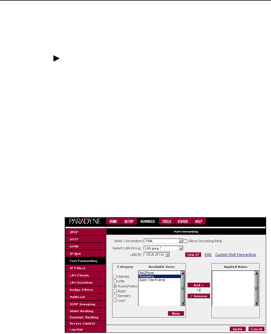
3. Using the Web Interface
3-26 January 2005 6381-A2-GB23-10
access an Internet application, they must use the WAN IP address. The port
forwarding feature will translate the WAN IP address into a LAN IP address.
To configure a service, game, or other application:
Procedure
1. From the Home screen, click on Advanced.
2. Under Advanced, select Port Forwarding.
3. Select the computer hosting the service and add the corresponding firewall
rule.
4. If you want to add a custom application, select the User category, click on
New, and fill in the port, protocols and description for your application.
For example, if you want to host a Netmeeting session, from the Home screen,
click on Advanced and under Advanced, select Port Forwarding. First select
the IP address for your Netmeeting server. Next select the Audio/Video
category and add Netmeeting to the Applied Rules box. To view the
management rules, highlight Netmeeting and select view. This will display the
preconfigured protocols and ports that Netmeeting will use. Now you can run
Netmeeting from your server and call users that are on the Internet. If they
know your WAN IP address, users can call you.
5. The Apply button will temporarily save these settings. To make the change
permanent, click on Tools and select System Commands. On the System
Commands page, click on Save All.
Figure 3-22. Port Forwarding: Netmeeting
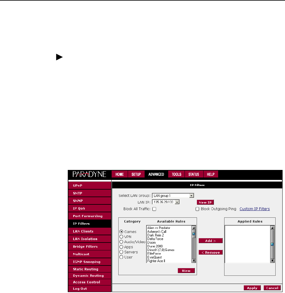
3. Using the Web Interface
6381-A2-GB23-10 January 2005 3-27
IP Filters
Use the IP Filters screen to block all or selected traffic. To set up IP Filters:
Procedure
1. From the Home screen, click on Advanced and under Advanced, select IP
Filters. The IP Filters screen appears.
2. Select the LAN Group from the drop-down list that these changes will apply to.
3. Select a LAN IP address from the LAN IP drop-down list. Click on New IP to
add a new IP address to the list.
4. Select available rules from the list, or click on Custom IP Filters to create a
new rule.
5. Click on Apply. The Apply button will temporarily save these settings. To make
the change permanent, click on Tools and select System Commands. On the
System Commands page, click on Save All.
Figure 3-23. IP Filters
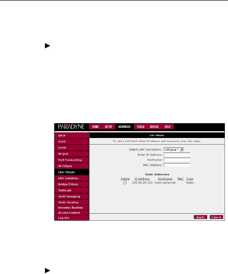
3. Using the Web Interface
3-28 January 2005 6381-A2-GB23-10
LAN Clients
To add a LAN client:
Procedure
1. From the Home screen, click on Advanced.
2. Under Advanced, select LAN Clients. If DHCP is used, all DHCP clients are
automatically assigned. If a fixed IP address server is on the LAN and you
want this server to be visible via the WAN, you must add its IP address. Once
the IP address has been added to you can apply Port Forwarding rules to this
IP address.
3. The Apply button will temporarily save these settings. To make the change
permanent, click on Tools and select System Commands. On the System
Commands page, click on Save All.
Figure 3-24. LAN Clients
LAN Isolation
Use the LAN Isolation screen to prohibit traffic between two LANs.
Procedure
1. From the Home screen, click on Advanced and under Advanced, select LAN
Isolation. The LAN Isolation screen appears.
2. Click in the Disable check box to prohibit traffic between the LANs.
3. The Apply button will temporarily save these settings. To make the change
permanent, click on Tools and select System Commands. On the System
Commands page, click on Save All.
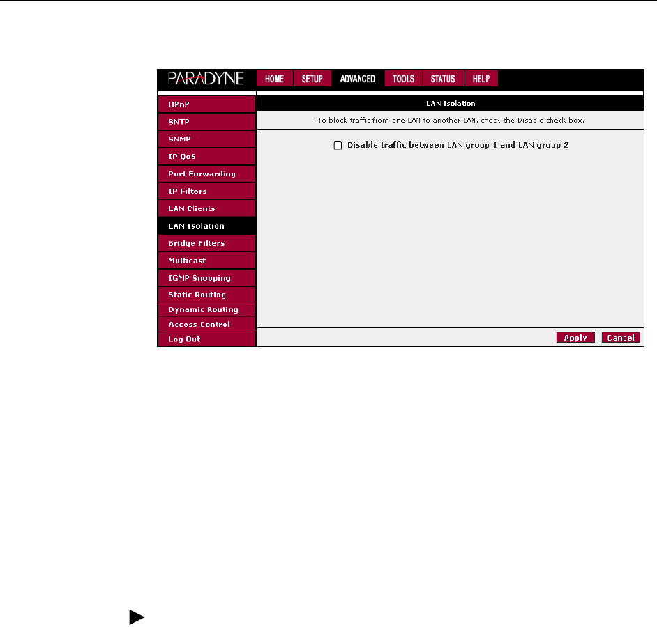
3. Using the Web Interface
6381-A2-GB23-10 January 2005 3-29
Figure 3-25. LAN Isolation
Bridge Filters
The bridge filtering mechanism provides a way for the users to define rules to
allow or deny frames through the bridge based on source MAC address,
destination MAC address and/or frame type. When bridge filtering is enabled,
each frame is examined against the defined filter rules sequentially, and when a
matched is determined, the appropriate filtering action (allow or deny) is
performed. The bridge filter will only examine frames from interfaces which are
part of the bridge itself. Twenty filter rules are supported with bridge filtering.
To enable Bridge Filters:
Procedure
1. From the Home screen, click on Advanced.
2. Under Advanced, select Bridge Filters. The Bridge Filters screen appears, as
shown in Figure 3-26, Bridge Filters.
The User Interface for Bridge Filter allows the user to add, edit, and delete, as well
as enable the filter rules. To add rules, define the source MAC address, destination
MAC address, and frame type with the desired filtering action (allow or deny), and
click on the Add button. The MAC address must be in a xx-xx-xx-xx-xx-xx format,
with 00-00-00-00-00-00 or blanks meaning any address.
To edit or modify an existing filter rule, select the desired rule created previously in
the Edit select box. The selected filter rule appears in the top section, as with the
Add procedure. Make the desired change to the MAC address, frame type and
access type, and click on Apply.
To delete a filter rules, select the filter rule entry to delete in the Delete selection
box. Note that multiple deletions are possible. Once all the desired filter rules are
selected for deletion, click on the Apply button. The Select All select box can also
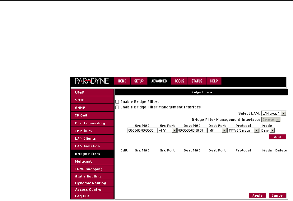
3. Using the Web Interface
3-30 January 2005 6381-A2-GB23-10
be used to delete the entire filter rule. It provides a quick method of selecting all
filter rules for deletion.
The Enable Bridge Filters button allows you to enable or disable bridge filtering. It
can be set or unset during any add, edit, or delete operation. It can also be set or
unset independently by pressing the Apply button.
Figure 3-26. Bridge Filters
Note: The bridge filter table contains three hidden rules. These rules are entered
automatically by the system to ensure that you don't lock yourself out of the
system. The first rule allows all ARP frames through the system. The second rule
allows all IPv4 frames with the destination MAC address of the router to go
through. The third rule allows all IPv4 frames with the source MAC address of the
router to go through.
The Apply button will temporarily save these settings. To make the change
permanent, click on Tools (at the top of the page) and select System Commands.
At the System Commands page, click on Save All.
Note: On a windows based machine, you can find a MAC address with the ipconfig
program. At a command prompt, type: ipconfig /all

3. Using the Web Interface
6381-A2-GB23-10 January 2005 3-31
Multicast
This option enables the IGMP proxy, which allows NAT clients to participate in
IGMP multicast groups. It should only be enabled if NAT is also enabled.
To enable Multicasting:
Procedure
1. From the Home screen, click on Advanced.
2. Under Advanced, select Muliticast.
3. Click in the check box to enable Multicast. Then select one or more available
connections.
The Apply button will temporarily save these settings. To make the change
permanent, click on Tools and select System Commands. On the System
Commands page, click on Save All.
Figure 3-27. Multicast
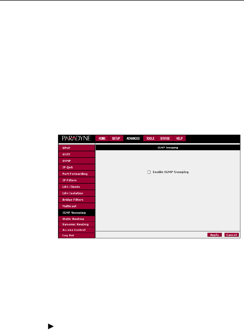
3. Using the Web Interface
3-32 January 2005 6381-A2-GB23-10
IGMP Snooping
Use the IGMP Snooping screen to specify whether IGMP Snooping is enabled.
When IGMP Snooping is enabled, the router analyzes Internet Group
Management Protocol (IGMP) packets to learn multicast group address and port
associations.
To enable IGMP Snooping:
1. From the Home screen, click on Advanced.
2. Under Advanced, select IGMP Snooping.
3. Click in the check box to enable snooping.
The Apply button will temporarily save these settings. To make the change
permanent, click on Tools and select System Commands. On the System
Commands page, click on Save All.
Figure 3-28. IGMP Snooping
Static Routing
If the router is connected to more than one network, you may need to set up a
static route between the networks. A static route is a predefined pathway that
network information must travel to reach a specific host or network. You can use
static routing to allow different IP domain users to access the Internet through the
router.
To enable Static Routing:
Procedure
1. From the Home screen, click on Advanced.
2. Under Advanced, select Static Routing.
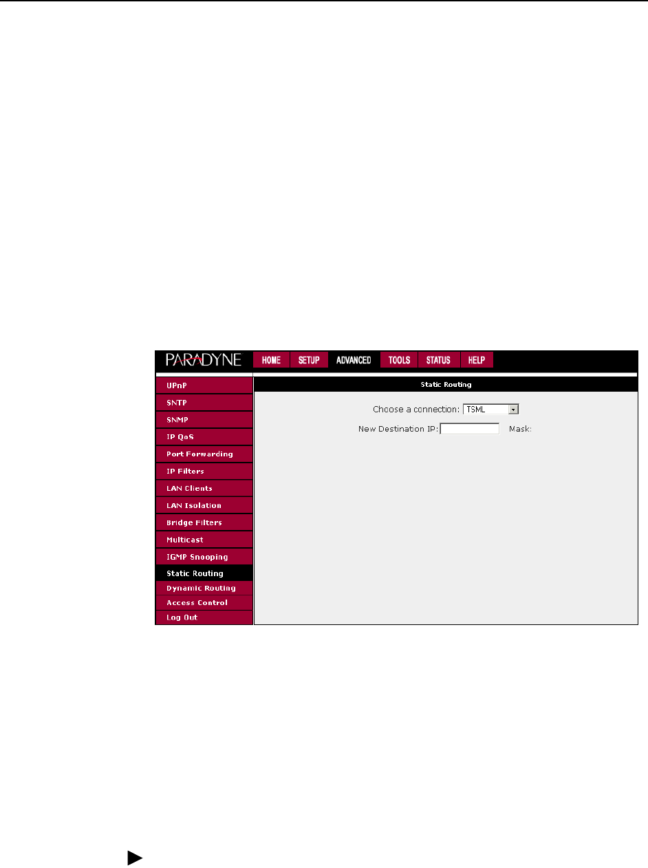
3. Using the Web Interface
6381-A2-GB23-10 January 2005 3-33
3. Specify the New Destination IP. This is the address of the remote LAN network
or host to which you want to assign a static route. Enter the IP address of the
host for which you wish to create a static route here. For a standard Class C IP
domain, the network address is the first three fields of the New Destination IP,
while the last field should be 0. The Subnet Mask identifies which portion of an
IP address is the network portion, and which portion is the host portion. For a
full Class C Subnet, the Subnet Mask is 255.255.255.0.
4. Specify the Gateway address. This is the IP address of the device that allows
contact between the router and the remote network or host.
5. Specify the Metric. This determines the maximum number of steps between
network nodes that data packets will travel. A node is any device on the
network (such as a router or switch).
6. The Apply button will temporarily save these settings. To make the change
permanent, click on Tools and select System Commands. On the System
Commands page, click on Save All.
Figure 3-29. Static Routing
Dynamic Routing
Dynamic Routing allows the router to automatically adjust to physical changes in
the network. The router, using the RIP protocol, determines the network packets'
route based on the fewest number of hops between the source and the
destination. The RIP protocol regularly broadcasts routing information to other
routers on the network.
To enable Dynamic Routing:
Procedure
1. From the Home screen, click on Advanced.
2. Under Advanced, select Dynamic Routing.
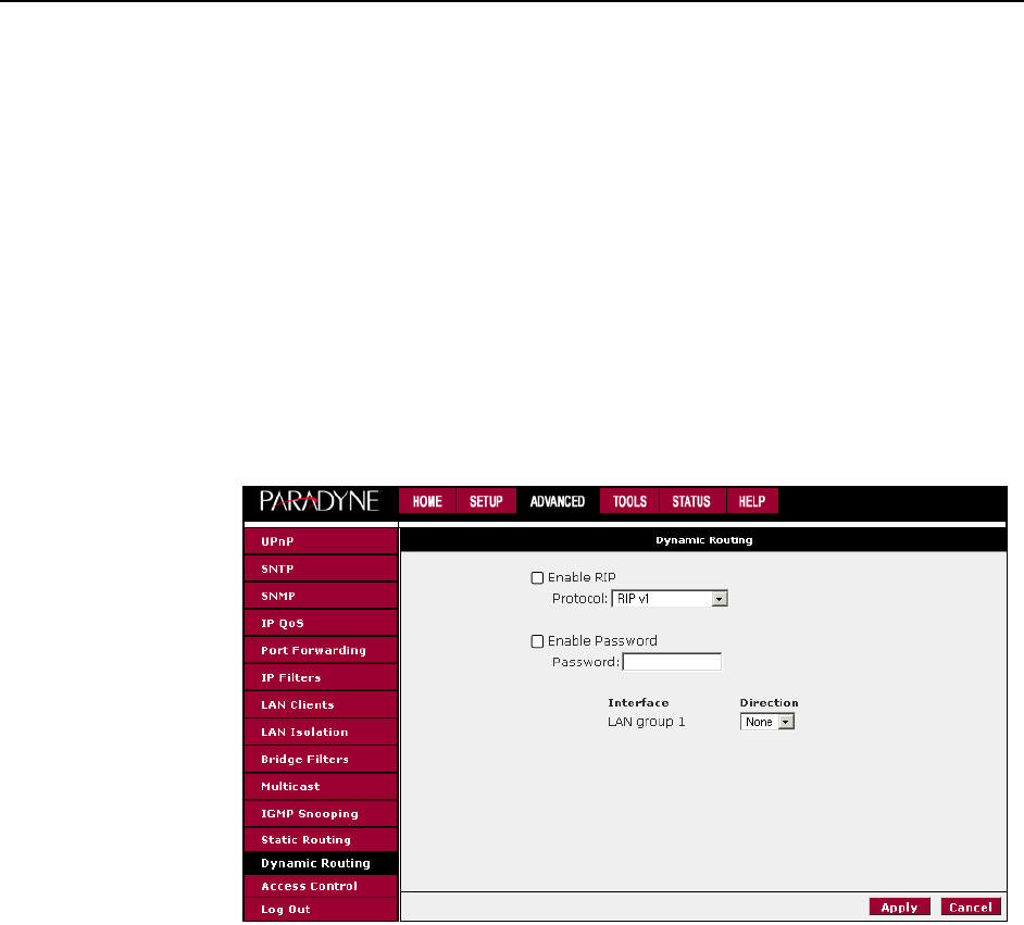
3. Using the Web Interface
3-34 January 2005 6381-A2-GB23-10
3. Specify the Protocol. The protocol is dependent upon the entire network. Most
networks support Rip v1. If RIP v1 is selected, routing data will be sent in RIP
v1 format. If Rip V2 is selected, routing data will be sent in RIP v2 format using
subnet broadcasting. If Rip V1 Compatible is selected, routing data will be
sent in RIP v2 format using multicasting.
4. Specify the Direction. This determines the direction that RIP routes will be
updated. Selecting In means that the router will only incorporate received RIP
information. Selecting Out means that the router will only send out RIP
information. Selecting both means that the router will incorporate received RIP
information and send out updated RIP information.
5. The Apply button will temporarily save these settings. To make the change
permanent, click on Tools and select System Commands. On the System
Commands page, click on Save All.
Figure 3-30. Dynamic Routing
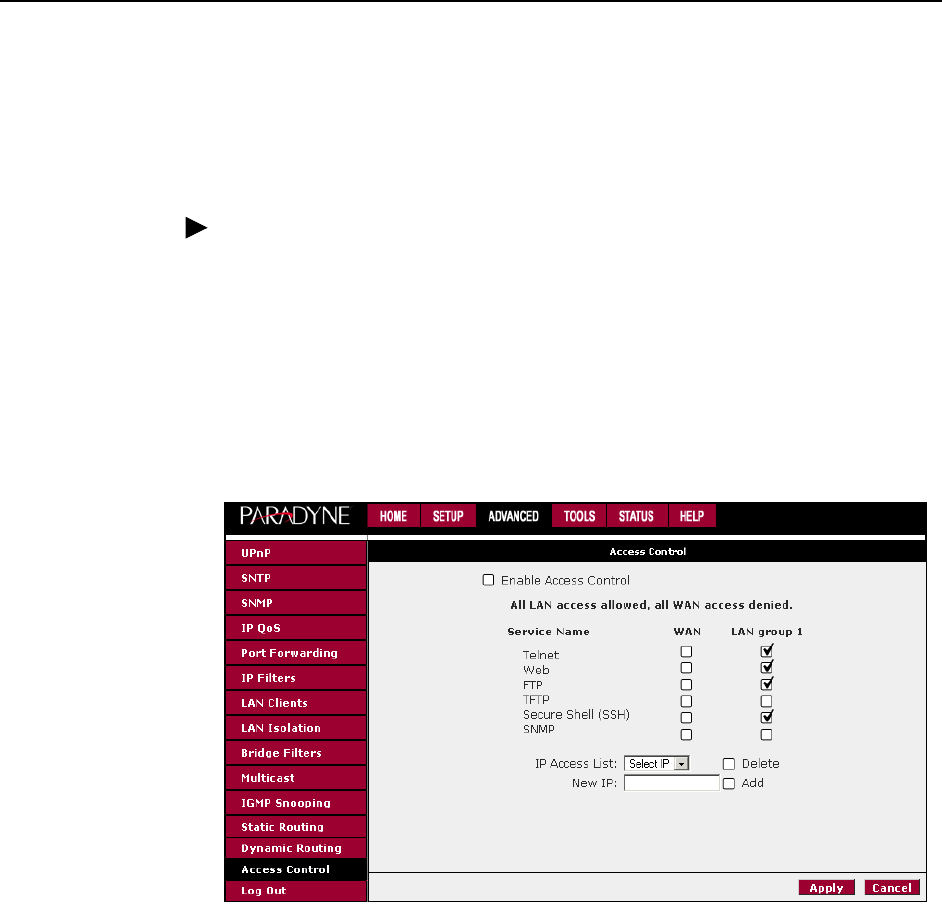
3. Using the Web Interface
6381-A2-GB23-10 January 2005 3-35
Access Control
Access control allows certain PCs to access the router after the firewall is enabled.
To enable any of the Access Control features:
Procedure
1. From the Home screen, click on Advanced.
2. Under Advanced, select Access Control. The Access Control screen appears.
All Access Control rules have precedence over rules that were added via the
Port Forwarding page.
3. The Apply button will temporarily save these settings. To make the change
permanent, click on Tools and select System Commands. On the System
Commands page, click on Save All.
Figure 3-31. Access Control
The Apply button will temporarily save these settings. To make the change
permanent, click on Tools (at the top of the page) and select System Commands.
At the System Commands page, click on Save All.
Log Out
Click on Log Out to close the session.

3. Using the Web Interface
3-36 January 2005 6381-A2-GB23-10
Tools
The Tools tab provides access to system commands and functions.
System Commands
To make changes permanent, click on Tools (at the top of the page) and select
System Commands. The following commands are used to configure the router:
Save all: Press this button in order to permanently save the current
configuration of the router. If you do restart the system without saving your
configuration, the router will revert back to the previously saved configuration.
Restart: Use this button to restart the system. If you have not saved your
configurations, the router will revert to the previously saved configuration upon
restarting. Connectivity to the unit will be lost. You can reconnect after the unit
reboots.
Restore Defaults: Use this button to restore factory default configuration.
Connectivity to the unit will be lost. You can reconnect after the unit reboots.
Remote Log
The remote log feature forwards all logged information to a remote PC. The type of
information forwarded to the remote PC depends upon the log level. Each log
message is assigned a severity level, which indicates how seriously the triggering
event affects router functions. When you configure logging, you must specify a
severity level for each facility. Messages that belong to the facility and are rated at
that level or higher are logged to the destination.
For PPPoE and PPPoA connections, select Debug if you want to log the
connection information. This is helpful when trying to debug connection problems.
Verify that the Debug box is checked on the PPPoA or PPPoE Connection Setup
screen.
Ta b le 3 - 2 defines the different severity levels.
Table 3-2. Severity Levels (1 of 2)
Severity Level Description
Panic System panic or other condition that causes the router to stop
functioning.
Alert Conditions that require immediate correction, such as a corrupted
system database.
Citical Potentially critical conditions, such as hard drive errors.
Error Error conditions that generally have less serious consequences
than errors in the panic, alert, and critical levels.
Warning Conditions that warrant monitoring.
Notice Conditions that are not errors but might warrant special handling.
Info Events or non-error conditions of interest.

3. Using the Web Interface
6381-A2-GB23-10 January 2005 3-37
To forward logging information, click on Tools and select Remote Log.
User Management
To change your router's username and password:
Procedure
1. From the Home screen, under the tools menu, click on User Management.
2. Change the login name and password.
3. If desired, you can change the idle timeout from this screen. The idle timeout
determines after how many minutes of inactivity the web interface is logged
off.
The Apply button will temporarily save these settings. To make the change
permanent, click on Tools (at the top of the page) and select System Commands.
At the System Commands page, click on Save All.
If you forget your password, you can press and hold the reset to factory defaults
button for 10 seconds. The router will be reset to its factory default configuration
and all custom configurations will be lost.
Figure 3-32. User Management
Debug Software debugging messages. Specify this level only if so directed
by your technical support representative.
Table 3-2. Severity Levels (2 of 2)
Severity Level Description

3. Using the Web Interface
3-38 January 2005 6381-A2-GB23-10
Update Gateway
You can remotely upgrade the router's firmware from the web interface.
To upgrade the firmware:
Procedure
1. From the Home screen, under the Tools title, click on Update Gateway.
2. Click on Browse, and find the firmware file to download. Make sure this is the
correct file.
3. Click on upgrade firmware. Once the upgrade is complete the router will
reboot. You will need to log back onto the router after the firmware upgrade is
complete.
The firmware upgrade should take less that 5 minutes to complete. If it takes
longer than 5 minutes, something has gone wrong.
Caution: Do not remove power from the router during the firmware upgrade
procedure.
Figure 3-33. Update Gateway
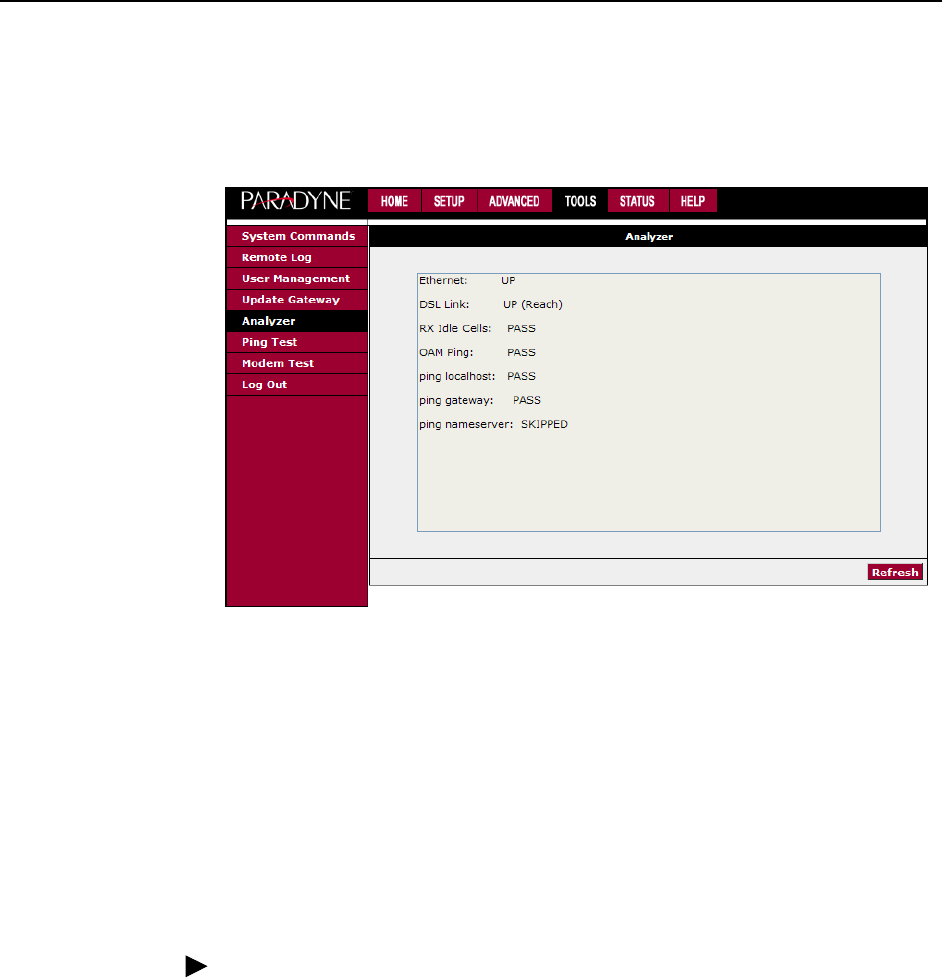
3. Using the Web Interface
6381-A2-GB23-10 January 2005 3-39
Analyzer
The Analyzer screen shows link statuses and test results.
Figure 3-34. Analyzer
Ping Test
Once you have your router configured, it is a good idea to make sure you can ping
the network. If you have your PC connected to the router via the default DHCP
configuration, you should be able to ping the network address 192.168.1.2. If your
ISP has provided their server address you can try to ping that address. If the pings
for both the WAN and the LAN side are successful, and you have the proper
protocols configured, you should be able to access the Internet.
To run a ping test:
Procedure
1. From the Home screen, under the Tools title, click on Ping Test.
2. Specify the target IP Address that you want to ping.
Optionally, specify:
— TOS Byte value. This is part of the IP header of the ping packet. Valid
values are 0 to 255.
— Packet size. Valid values are 36 to 65507.
— Number of echo requests. Valid values are 1 to 9.
3. Click on Test.
By default, when you select ping test, the router will ping itself three times. In
Figure 3-35, the router passed the Ping Test; this basically means that the TCP/IP
protocol is up and running. If this first test does not pass, the TCP/IP protocol is
not loaded. In this case, restart the router.
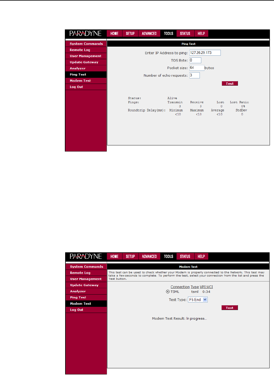
3. Using the Web Interface
3-40 January 2005 6381-A2-GB23-10
Figure 3-35. Ping Test
Modem Test
The Modem Test is used to check whether your router is properly connected to the
WAN Network by running OAM F4 and F5 end-to-end and segment tests. The test
may take a few seconds to complete. To perform the test, select your connection
from the list, select a Test Type, and click on the Test button.
Before running this test, make sure you have a valid DSL link; if the DSL link is not
connected, this test will always fail. Also, the DSLAM must support this feature.
Not all DSLAMs have OAM F4 and F5 support.
Figure 3-36. Modem Test
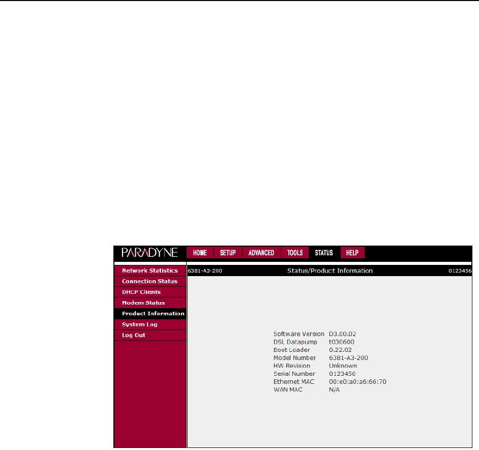
3. Using the Web Interface
6381-A2-GB23-10 January 2005 3-41
Status
The Status section allows you to view the Status/Statistics of different connections
and interfaces:
Network Statistics – Select to view the Statistics of different interfaces:
Ethernet, USB, and DSL.
Connection Status – Select to view the Status of different connections.
DHCP Clients – Select to view the list of DHCP clients.
Modem Status – Select to view the Status and Statistics of your broadband
(DSL) connection.
Product Information – Select to view the router's driver and run-time
information, as shown in Figure 3-37.
Figure 3-37. Product Information
System Log – Select to view all logged information. Depending upon the
severity level, this logged information will generate log reports to a remote host
(if remote logging is enabled).

3. Using the Web Interface
3-42 January 2005 6381-A2-GB23-10

6381-A2-GB23-10 January 2005 4-1
4
Troubleshooting
The Router Is Not Functional
1. Check to see that the power LED is green and the network cables are installed
correctly. Refer to the quick start guide for more details.
2. Check to see that the LAN and Status LEDs are green.
3. Make sure you are not connecting the USB and the Ethernet port to the same
PC at the same time.
4. Check the settings on your PC. Again, refer to the quick start guide for more
details
5. Check the router's settings.
6. From your PC, can you ping the router? Assuming that the router has DHCP
enabled and your PC is on the same subnet as the router, you should be able
to ping the router.
7. Can you ping the WAN? Your ISP should have provided the IP address of their
server. If you can ping the router and your protocols are configured correctly,
you should be able to ping the ISP's network. If you cannot ping the ISP's
network, make sure you are using the correct protocols with the correct
VPI/VCI values.
8. Make sure NAT is enabled if you are using private addresses on the LAN
ports.
You Cannot Connect to the Router
1. Check to see that the power LED is green and that the network cables are
installed correctly.
2. Make sure you are not connecting the USB and the Ethernet port to the same
PC at the same time.
3. Make sure that your PC and the router are on the same network segment. The
router's default IP address is 192.168.1.1. If you are running a Windows-based
PC, type ipconfig /all (or winipcfg /all on Windows 95, 98, or ME) at a
command prompt to determine the IP address of your network adapter. Make
sure that it is within the same 192.168.1.x subnet. Your PC's subnet mask

4. Troubleshooting
4-2 January 2005 6381-A2-GB23-10
must match the router's subnet mask. The router has a default subnet mask of
255.255.255.0.
4. Make sure NAT is enabled if you are using private addresses on the LAN
ports.
LEDs Blink in a Sequential Pattern
This typically means that either the kernel or flash file system is corrupted. Notify
your service representative.
The Status LED Continues to Blink
This means that the DSL line is trying to train but for some reason it cannot
establish a valid connection. The likely cause of this is that you are too far away
from the central office. Contact your DSL service provider for further assistance.
The Status LED is Always Off
1. Make sure you have DSL service. You should receive notification from your
ISP that DSL service is installed. You can usually tell if the service is installed
by listening to the phone line: you will hear some high-pitched noise. If you do
not hear high-pitched noise, contact your ISP.
2. Verify that the phone line is connected directly to the wall and to the line input
on the router. If the phone line is connected to the phone side of the router or
you have a splitter installed on the phone line, the DSL light will not come on.

6381-A2-GB23-10 January 2005 A-1
A
Terminology
What is a Firewall?
A firewall is protection between the Internet and your local network. It acts as the
firewall in your car does, protecting the interior of the car from the engine. Your
car's firewall has very small opening that allow desired connections from the
engine into the cabin (gas pedal connection, etc), but if something happens to your
engine, you are protected.
The firewall in the router is very similar. Only the connections that you allow are
passed through the firewall. These connections normally originate from the local
network, such as users web browsing, checking e-mail, downloading files, and
playing games. However, you can allow incoming connections so that you can run
programs like a web server.
What is NAT?
NAT stands for Network Address Translation. Another name for it is Connection
Sharing. What does this mean? Your ISP provides you with a single network
address to access the Internet with. However, you may have several machines on
your local network that want to access the Internet at the same time. The router
provides NAT functionality that converts your local network addresses to the single
network address provided by your ISP. It keeps track of all these connections and
makes sure that the correct information gets to the correct local machine.
Occasionally, there are certain programs that don't work well through NAT. Some
games and other specialty applications have a bit of trouble. The router contains
special functionality to handle the vast majority of these troublesome programs
and games. NAT does cause problems when you want to run a server. See the
DMZ section below.
What is a DMZ?
DMZ really stands for Demilitarized Zone. It is a way of separating part of your
local network so that is more open to the Internet. Suppose that you want to run a
web server, or a game server. Normal servers like these are blocked from working
by the NAT functionality. The solution is to isolate the single local computer into a
DMZ. This makes the single computer look like it is directly on the Internet, and
others can access this machine.

A. Terminology
A-2 January 2005 6381-A2-GB23-10
Your machine isn't really directly connected to the Internet, and it really has an
internal local network address. When you provide the server's network address to
others, you actually provide the address of the router. The router fakes the
connection to your machine.
You should use the DMZ when you want to run a server that others will access
from the Internet. Internal programs and servers (like print servers) should not be
connected to the DMZ.
What is a Router?
The Internet is so large that a single network cannot handle all of the traffic and
still deliver a reasonable level of service. To overcome this limitation, the network is
broken down into smaller segments or subnets that can deliver good performance
for the stations attached to that segment. This segmentation solves the problem of
supporting a large number of stations, but introduces the problem of getting traffic
from one subnet to another.
To accomplish this, devices called routers are placed between segments. If a
machine wishes to contact another device on the same segment, it transmits to
that station directly using a simple discovery technique. If the target station does
not exist on the same segment as the source station, then the source actually has
no idea how to get to the target.
One of the configuration parameters transmitted to each network device is its
default gateway. This address is configured by the network administrators and it
informs each personal computer or other network device where to send data if the
target station does not reside on the same subnet as the source. If your machine
can reach all stations on the same subnet (usually a building or a sector within a
building), but cannot communicate outside of this area, it is usually because of an
incorrectly configured default gateway.

6381-A2-GB23-10 January 2005 IN-1
Index
A
Access Control, 3-35
Activity LED, 1-3
ADSL, 1-1
ADSL/R, 1-1
ADSL2+, 1-1
Advanced Features, 3-22
Analyzer screen, 3-39
Assigning IP address by DHCP, 2-6
B
Back Panel, 1-2
Bridge, 1-1
Connection, 3-13
Filters, 3-29
C
Cables
Included, 1-3
Installing, 2-1
CE Marking, B
Changing IP address, 3-20
CLIP Connection, 3-15
Configuring
LAN, 3-18
PC, 2-3
PC’s IP Address, 2-6
WAN, 3-6
Connecting Hardware, 2-1
CPE update feature, 3-24
D
Declaration of Conformity, D
default settings, 1-2
Definitions, 1-1
DHCP
Connection Setup, 3-12
Enable/Disable, 3-19
DMZ, Explained, A-1
DoC, D
Document
Feedback, A
Purpose and Intended Audience, v
Summary, v
Driver Installation, 2-3
Dynamic Routing, 3-33
E
EMI Notice
Canada, D
Japan, E
ending session, 3-35
end-to-end test, 3-40
F
factory default settings, 1-2
FCC Part 15 Declaration, B
Features of the 6381 Router, 1-1
Filters, IP, 3-27
Firewall
Enabling, 3-21
Explained, A-1
Firewall/NAT Services, 3-21
Firmware Upgrade, 3-38
Found New Hardware Wizard, 2-3
H
Hardware Installation, 2-1
Home Page, 3-2
I
ICMP echo request, 3-39
IGMP Snooping, 3-32
Important Safety Instructions, B
IP Address
assigning by DHCP, 2-6
of PC, 2-6
of Router, 3-20
trap upon change, 3-24
IP Filters, 3-27
IP QoS, 3-25
J
Japan Notices, E

Index
IN-2 January 2005 6381-A2-GB23-10
L
LAN
Clients, 3-28
Configuring, 3-18
Connection, 3-5
Isolation, 3-28
LED, 1-3
LED
Blinking in a Sequential Pattern, 4-2
Description, 1-3
Status LED Continues to Blink, 4-2
Logging Into Your Router, 3-1
Logging out, 3-35
M
Management link (TSML), 3-17
Modem
Setup, 3-17
Test, 3-40
Modify Existing Connection, 3-16
Modulation Type, 3-17
Multicast, 3-31
N
NAT, Explained, A-1
New Connection, 3-7
NOC access, 3-17
Notice
to Users of the Canadian Telephone Network, D
to Users of the United States Telephone Network, C
O
OAM F4 and F5 tests, 3-40
P
packet size, 3-39
Packing List, 1-4
Password, 3-1
Ping Test, 3-39
Port Forwarding, 3-25
Power LED, 1-3
PPPoA
Connection Setup, 3-9
Troubleshooting, 3-36
PPPoE
Connection Setup, 3-7
Support, 1-2
Troubleshooting, 3-36
Product-Related Documents, vi
PVC Support, 1-2
Q
QoS, 3-25
Quality of Service, 3-25
Quick Start Options, 3-4
R
ReachDSL, 1-1
Remote Log, 3-36
Requirements, 1-2
Reset Button, 1-2
Router, 1-1
Routing
Dynamic, 3-33
Static, 3-32
S
Saving changes, 3-5
segment test, 3-40
Setup, 3-5
Severity Levels, 3-36
Shipping List, 1-3
Simple Network Management Protocol, 3-24
Simple Network Time Protocol, 3-23
SNMP, 3-24
SNTP, 3-23
Static
Connection Setup, 3-11
Routing, 3-32
Status, 3-41
Status LED, 1-3
Always Off, 4-2
Continues to Blink, 4-2
Supplier's Declaration of Conformity, D
System
Commands, 3-36
Requirements, 1-2
T
Tests
OAM F4 and F5, 3-40
Ping, 3-39
results, 3-39
Tools, 3-36
TOS byte, 3-39
Trademarks, A
Traps, 3-24
Troubleshooting, 4-1
PPPoA and PPPoE connections, 3-36
Troubleshooting Management Link, 3-17
TSML, 3-17

Index
6381-A2-GB23-10 January 2005 IN-3
U
UDP, 3-31
Update Gateway, 3-38
Upgrade Firmware, 3-38
UpnP, 3-22
USB
Driver Installation, 2-3
LED, 1-3
User Management, 3-37
Username, 3-1
W
WAN
Configuring, 3-6
Connection, 3-5
Warranty, Sales, Service, and Training Information, A
Windows
2000, 2-8
95, 98, 2-10
ME, 2-9
NT 4.0, 2-11
USB Driver Installation, 2-3
XP, 2-6

Index
IN-4 January 2005 6381-A2-GB23-10
