Park Air Systems BT6MBS User Manual User Guide
Park Air Systems Limited User Guide
User Guide
T6M Base Station
User Guide
Handbook Part Number: 31-360T6MBS

Handbook Title: T6M Base Station User Guide
Handbook Part Number: 31-360T6MBS
Issue Number: one
Date of Issue: September 2000
Published by: Park Air Electronics
Northfields
Market Deeping
Peterborough
England
Telephone: From UK, 01778 345434
From outside UK, 44 1778 345434
Fax: From UK, 01778 342877
From outside UK, 44 1778 342877
T6M Base Station User Guide
Page 2

Amendment Record
Amendments to this User Guide, initiated by PAE, are recorded in the following table.
Amendment
Number
Incorporated
by:
Date Brief Details
Modification Record
Modifications to the T6M base station, authorized by PAE, are recorded
in the following table.
Modification
Number
Embodied by: Date Brief Details
T6M Base Station User Guide
Page 3
Changes or modifications to the T6M base station that are not expressly approved by
Park Air Electronics could void your authority to operate the equipment.

SAFETY
Warnings
[Failure to comply with warnings can result in personal injury, fire, or electric shock.]
qDO NOT operate equipment at high volume levels. Hearing experts advise against continuous
high volume operation. If you experience ringing in your ears, reduce the volume level, or
discontinue use.
qThe Radio module's power amplifier circuit contains beryllium oxide that can be extremely toxic.
No instructions within this user guide remove any of the radio module's covers so users are not
exposed to a potential beryllium hazard. If the radio module is to be disposed of, users must be
aware of current disposal regulations regarding equipment containing beryllium.
qThe antenna used with this radio equipment must be installed such that the resultant radiated
field strength is below 10 W/m²in areas normally accessible to personnel.
qThe base station can be fitted with an optional internal battery. It is a sealed lead-acid type with a
thixotropic electrolyte. The battery has self sealing safety vents that may release small quantities
of gas under extreme conditions. Because of this, users must ensure that the enclosure's vents
are always free from obstruction.
FEDERAL COMMUNICATIONS COMMISSION (FCC) REGULATIONS
qThis device complies with Part 15 of the FCC Rules. Operation is subject to the condition that this
device does not cause harmful interference.
qYou are required to obtain a station licence before transmitting from your base station.
qThis equipment is only licenced for operation on 25 kHz channel spacing. Operation on 8.33 kHz
channel spacing is not allowed within the USA.
qThe base station power output must not exceed the output necessary for satisfactory technical
operation taking account of local conditions and the area to be covered.
qThe base station's frequency and parameters should be checked by authorized service
personnel before use, and at least yearly thereafter.
T6M Base Station User Guide
Page 4

FOREWORD
This user guide describes the purpose, installation, and operation of the Park Air Electronics (PAE) T6M
base station. Read all instructions given in this user guide before operating the equipment.
TRADEMARKS
The following trademarks are used in this user guide.
IBM Is a registered trademark of International Business Machines.
Microsoft Is a registered trademark of Microsoft Corporation in the USA and other countries.
Windows Is a registered trademark of Microsoft Corporation in the USA and other countries.
T6M Base Station User Guide
Page 5

T6M Base Station User Guide
Page 6
CONTENTS
SAFETY 4
Federal Communications Commission (FCC) Regulations 4
Foreword 5
Trademarks 5
Chapter 1 - Overview 9
About this Handbook 9
Associated Handbook 9
Introduction to the T6M Base Station 9
Facilities 10
Remote Controllers 10
Power Supplies 10
Programming the Base Station's Personality 10
Options 11
Internal Battery 11
Rack Mount Option 11
Local Monitoring of Transmitted Audio 11
Chapter 2 - Specification 13
General 13
Dimensions and Weight 14
Input Supplies 14
ac Supply 14
dc Supply 14
Optional Internal Battery 14
Receive Circuit 15
Transmit Circuit 15
Chapter 3 - Operation 17
Introduction 17
Front Panel Controls 18
Display 18
Transmit Indicator 18
Busy Indicator 18
Power Indicator 18
Microphone/Diagnostics Connector 18
Volume Control 18
External Tx Inhibit Indicator 18
Battery Indicator 18
Loudspeaker Grille 18
PRI Button 19
SQL Button 19
SELsand SELtButtons 19

T6M Base Station User Guide
Page 7
CHsand CHtButtons 19
SCN Button 19
VOLsand VOLtButtons 19
Power Button 19
Switching On and Off 20
Operating the Base Station in Normal Mode 21
Selecting Normal Mode 21
Selecting a Channel Frequency 21
Transmitting and Receiving 21
Switching and Adjusting the Squelch Facility 21
Operating the Base Station in Priority Mode 23
Selecting Priority Mode 23
Selecting a Priority Channel Frequency 23
Transmitting and Receiving 23
Operating the Base Station in Scan Mode 24
Selecting Scan Mode 24
Selecting a Scan Group 24
Transmitting and Receiving 24
Programmable Options 25
Display Blanking 25
Warning Beeps 25
Key Beeps 25
Transmit Inhibit 26
Maximum Transmit Time 26
Front Panel Display for 25 kHz and 8.33 kHz Channel Spacing 26
Fault and Error Codes 28
Chapter 4 - Installation 29
Introduction 29
Unpacking 30
Setting Internal Links 30
Siting the Base Station 31
Connecting a T6M Controller to the Base Station 31
Connecting an antenna 31
Connecting the Chassis Stud to Earth 31
Connecting a microphone 32
Securing the Microphone Bracket 32
Connecting External Facilities 33
Connecting a dc Input Supply 35
Connecting an ac Input Supply 36
Connecting a PC to the Base Station 36
Chapter 5 - Programming the Base Station 37
Introduction 37
Programmable Options 39
Display Blanking 39

T6M Base Station User Guide
Page 8
Warning Beeps 39
Key Beeps 39
Hold on Scan Mode 40
Installing the Programming Software onto a Laptop, or PC 40
Creating a New Personality 40
Saving a Personality 44
Opening a Saved Personality 45
Loading a Personality into the Radio 45
Reading a Personality from the Radio 45
Printing a Personality Report 46
Chapter 6 - Spares 47
Introduction 47
List of Spares 47
Chapter 7 - Maintenance 49
Scheduled Maintenance 49
Test Equipment Required 49
Test Lead 49
Transmit Power and Frequency Accuracy Test 50
Receiver Sensitivity Check 52
Battery Replacement 52
Fault Finding 53
Replacing Modules 55
Chapter 8 - Figures 57

Chapter 1 - Overview
This chapter gives a brief overview of the T6M base station and its facilities.
ABOUT THIS HANDBOOK
This handbook describes the Park Air Electronics (PAE) T6M Base Station. Its purpose is to provide the
information necessary for users to install, operate, and maintain the equipment to module level. To
achieve this, the handbook is divided into eight chapters as follows:
Chapter 1. Gives a brief overview of the equipment and its facilities.
Chapter 2. Provides the equipment specification.
Chapter 3. Details the equipment's controls, indicators and connectors, and provides the
operating instructions.
Chapter 4. Provides detailed installation procedures and defines all interfaces.
Chapter 5. Describes how the base station's ‘personality’ can be changed.
Chapter 6. Lists the spares available for the base station.
Chapter 7. Gives maintenance information.
Chapter 8. Contains the A3 size figures that are referred to throughout this user guide.
Associated Handbook
When reading this handbook it may be necessary to refer to the following handbook:
T6M Controller User Guide. Part number 31-3600T6MC.
INTRODUCTION TO THE T6M BASE STATION
The T6M multichannel base station provides two-way communication within the VHF aeronautical
frequency band 118 to 136.9916 MHz. The radio provides a nominal 10 watt amplitude modulated (AM)
output, and operates on both 25 kHz and 8.33 kHz spaced channel frequencies. A fist microphone, with
an integral PTT switch, is provided for transmissions; received signals are monitored through the built-in
loudspeaker.
Before use, the radio's ‘personality’ is programmed into its internal memory. The personality defines up
to 760 channel frequencies, the required operating modes, and various secondary options. Three
operating modes are available: Normal, Priority, and Scan.
Normal Mode In normal mode, any channel frequency programmed into the base station can
be selected using the front panel controls. Up to 760 channel frequencies can
be programmed into the radio's personality.
Priority Mode Priority mode allows faster access to frequently used channels. Up to 15 of the
channel frequencies that are available in Normal mode can be programmed
into the priority list.
Scan Mode If scan mode is selected, the radio scans a number of pre-defined channels
searching for a ‘busy’ one. When a busy channel is found, and depending on
the programmed options, the radio remains tuned to that channel. Up to 15
scan groups can be set up, each group containing up to 15 channel
frequencies.
T6M Base Station User Guide
Page 9

FACILITIES
A facilities connector is fitted to the base station's rear panel. It provides the following interfaces:
qAudio in/out and PTT control for connection to a Voice Communication and Control System
(VCCS).
qAudio out for connection to a tape recording system.
qAn audio operated squelch signal that allows an external ‘busy’ indication.
qA transmit inhibit input signal. This input may be used to prevent the base station being keyed.
REMOTE CONTROLLERS
Up to four T6M Controllers can be connected to a base station. Each controller allows remote
transmission and reception on the frequency currently selected at the base station. Full details of the
controller are contained in the T6M Controller User Guide.
POWER SUPPLIES
The base station can operate from an ac mains supply, an external dc supply, or an internal battery (see
‘Options’ on page 11). When both an ac and a dc supply are connected, the base station operates from
the ac input; the dc input acts as a backup in case the mains fails.
PROGRAMMING THE BASE STATION'S PERSONALITY
The base station's ‘personality’ is programmed into its internal memory and defines up to 760 channel
frequencies, the required operating modes, and various secondary options. When the equipment is
received from PAE, the personality is either:
qA personality programmed to the user's specific requirements.
or,
qA default personality that covers the 760 channels (25 kHz spaced) available in the VHF
aeronautical frequency band. No frequencies are allocated to the priority list, and no scan
groups are set.
A programming kit is available from PAE. This allows a new personality to be programmed into the radio
at any time.
The kit comprises software loaded on a CD-ROM, and a programming lead. An IBM™ compatible
laptop, or Personal Computer (PC) running Microsoft Windows™ 95 or 98 must be available to
reprogramme the radio.
To order the programming kit, contact PAE quoting part number 70-T6MPMKIT.
T6M Base Station User Guide
Page 10

OPTIONS
Internal Battery
An internal battery can be fitted to act as a backup should the ac mains supply fail. This option may be
required when no external dc backup supply is available.
The battery is float charged from the ac supply. If the mains fails, the battery provides a minimum two
hours of operation, at 25°C, provided the duty cycle does not exceed 10%. When operating from the
internal battery, the transmit power output is reduced by up to 3 dB.
When the battery option is fitted, link JP2 on the interface module must be correctly set (see ‘Setting
Internal Links’ in the installation chapter).
Rack Mount Option
The base station is normally supplied in a free-standing desktop polymer enclosure. As an option, the
base station's chassis can be fitted in a metal enclosure suitable for 19 inch (483 mm) rack mounting.
Local Monitoring of Transmitted Audio
Normally, transmit and received audio is monitored through the base station's internal loudspeaker; this
allows a base station operator to monitor both sides of voice traffic when remote controllers are being
used. Alternatively, the equipment can be configured so that only receiver audio is monitored through the
loudspeaker.
This facility is enabled by setting link JP1 on the interface module (see ‘Setting Internal Links’ in the
installation chapter).
T6M Base Station User Guide
Page 11

Intentionally Blank
T6M Base Station User Guide
Page 12

Chapter 2 - Specification
Chapter 2 gives the specification of the T6M base station.
GENERAL
The general parameters of the T6M base station are listed below.
Operation Simplex VHF AM transmit and receive.
Operating modes Normal, priority, and scan.
Channel bandwidth 25 kHz and 8.33 kHz.
Frequency range (at 25 kHz) Between 118 and 136.975 MHz.
Frequency range (at 8.33 kHz) Between 118 and 136.9916 MHz.
Frequency stability ±1.5 ppm
Channel selection In Normal mode up to 760 channel frequencies can be
programmed into the radio. The channels can have
25 kHz spacing, 8.33 kHz spacing, or a mixture of both.
Priority mode allows up to 15 of the stored channels to
be allocated to a priority list. Channel selection can then
be limited to those frequencies in the priority list.
In Scan mode, the radio can have up to 15 scan groups
each containing up to 15 channel frequencies.
Duty cycle (receive) Continuous.
Duty cycle (transmit) 25% with a maximum transmit time of 5 minutes. A
longer transmit time, or a higher duty cycle, reduces the
output power by up to 6 dB.
When the base station operates from the optional
internal battery, a duty cycle above 10% rapidly
discharges the battery (see ‘Optional Internal Battery’ on
page 14).
Operating temperature range Between -20°C and +55°C.
Storage temperature range Between -40°C and +70°C.
Humidity Can be operated in humidity up to 80%.
Cooling Fan assisted air flow. Fan turns on at approximately
40°C; the fan's speed increases as temperature
increases.
T6M Base Station User Guide
Page 13

DIMENSIONS AND WEIGHT
The dimensions and weight of the base station fitted within the standard enclosure are:
Width 446 mm.
Height 176 mm.
Depth 400 mm.
Weight 9.5 kg without battery option fitted.
11.5 kg with battery option fitted.
The dimensions and weight of the rack mounted base station are:
Width 483 mm.
Height 89 mm (2U).
Depth 423 mm.
Weight 9 kg without battery option fitted.
11 kg with battery option fitted.
INPUT SUPPLIES
The base station can operate from an ac mains supply, or an external dc input supply. When both
supplies are connected, the dc supply acts as a backup supply should the mains fail.
ac Supply
The base station requires the following ac input supply:
Input voltage Between 98 and 254 V ac at either 50 or 60 Hz.
Maximum current 2 A.
dc Supply
The base station requires the following dc input supply:
Input voltage Between 12 and 15.5 V. For maximum transmitter output
power, the dc input must be between 14 and 15.5 V.
Maximum current 9 A.
OPTIONAL INTERNAL BATTERY
An optional internal battery can be fitted to power the base station when external supplies fail. The
battery provides:
Voltage 12 V dc.
Operating time The battery provides at least two hours of operation
when the duty cycle does not exceed 10% (measured at
a working temperature of 25°C). The transmitter output
power is reduced by up to 3 dB during battery operation.
T6M Base Station User Guide
Page 14

RECEIVE CIRCUIT
The specification of the receive circuit is listed below.
Sensitivity -104 dBm at 30% modulation depth for 10 dB (S+N):N.
Selectivity 8.33 kHz spaced: <6 dB at ±3 kHz; >60 dB at ±8.33 kHz.
25 kHz spaced: <6 dB at ±8.5 kHz; >70 dB at ±25 kHz.
Intermodulation suppression >70 dB.
Spurious response suppression >80 dB.
Audio power output 2 W into 8 ohm integral speaker (<10% THD).
Distortion <10% THD for 90% modulation depth.
RF input impedance 50 ohms.
TRANSMIT CIRCUIT
The specification of the transmit circuit is listed below.
RF output power Adjustable between approximately 5 and 12 W.
Spurious <-46 dBm when more than 1 MHz from the carrier.
Harmonics <-36 dBm.
Modulation depth Up to 85%. Compression above 85% to prevent over
modulation.
RF load impedance 50 ohms.
Frequency stability ±1.5 ppm.
T6M Base Station User Guide
Page 15

Intentionally Blank
T6M Base Station User Guide
Page 16

Chapter 3 - Operation
This chapter gives the instructions for operating the base station after it has been correctly installed.
Users should note that the facilities available to an operator depend on how the radio's personality has
been configured.
INTRODUCTION
The base station provides transmission and reception on any 25 kHz, or 8.33 kHz, spaced channel
frequency within the VHF aeronautical frequency band between 118 and 136.9916 MHz. However, only
those frequencies and operating modes that are pre-programmed into the radio can be selected. The
radio can be reprogrammed at any time using the supplied software. Instructions for doing this are given
in chapter 5 starting on page 37.
Three operating modes are available: Normal, Priority, and Scan. In Normal mode, any frequency
programmed into the system can be selected using the radio's front panel controls. Priority mode is
similar to Normal mode, but allows faster selection of up to 15 frequently used channels.
In Scan mode, the radio scans a number of pre-defined channels searching for a ‘busy’ one. When a
busy channel is found, and depending on the programmed options, the radio remains tuned to that
channel ready for use. Scanning can be resumed at any time.
The following topics are covered in this chapter:
qDescription of front panel controls and indicators; page 18.
qSwitching on and off; page 20.
qOperating the base station in normal mode; page 21.
qOperating the base station in priority mode; page 23.
qOperating the base station in scan mode; page 24.
qProgrammable options; page 25.
qFront panel display for 25 kHz and 8.33 kHz channel spacing; page 26.
qFault and error codes; page 28.
T6M Base Station User Guide
Page 17
When a T6M base station is received from PAE, the personality is either:
qA personality programmed to the user's specific requirements.
or,
qA default personality that covers the 760 channels (25 kHz spaced) available in the VHF
aeronautical frequency band. No frequencies are allocated to the Priority list, and no scan
groups are set.
A programming kit is available from PAE. This allows a new personality to be programmed and downloaded.
The radio does not have to be removed from its installed position to download a new personality.
Note that operation using 8.33 kHz channel spacing is not currently allowed within the USA.

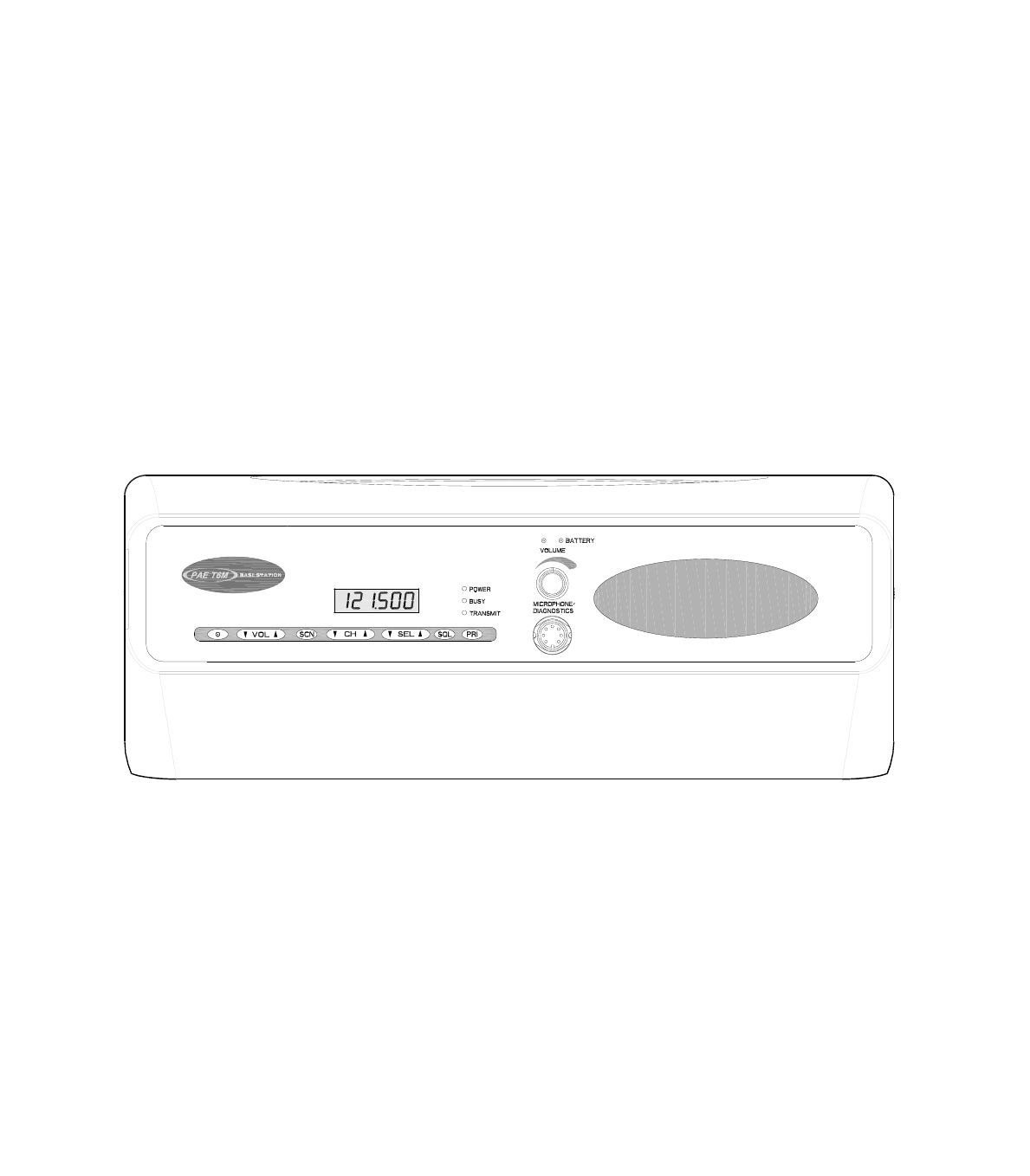
FRONT PANEL CONTROLS
Display
(Figure 3, Item 1). In Normal mode, the display shows the currently selected channel frequency. In
Priority mode, the display shows the channel frequency but alternates to show a ‘P’ every few seconds.
In Scan mode, and when the radio is scanning, the display shows Scn and the currently selected scan
group (a number between 1 and 15). When a busy channel is found, the channel's frequency is
displayed.
The display, in the event of a detected unserviceability, shows fault and error codes.
Transmit Indicator
(Figure 3, Item 2). A red indicator that lights when the transmitter is keyed and producing power.
Busy Indicator
(Figure 3, Item 3). A yellow indicator that lights when a signal, of sufficient strength to overcome the
squelch circuit, is received. This indicator is always lit when the squelch facility is switched off.
Power Indicator
(Figure 3, Item 4). A green indicator that lights when the radio is switched on by pressing the front panel
Power button. The front panel Power button cannot be operated unless the rear panel power switch is set
to on. Note that when the radio is switched off using the front panel Power switch, and the rear panel
switch remains at on, the internal battery (if fitted) continues to charge.
Microphone/Diagnostics Connector
(Figure 3, Item 5). A 7-pin DIN socket used to connect the fist microphone normally supplied with the
base station. This connector will also accept a microphone/headset; the connector's pin-out is shown on
page 32.
This socket is also used to connect the base station to a laptop, or PC, so that the base station's
personality can be programmed.
Volume Control
(Figure 3, Item 6). A rotary control used to adjust the volume of the internal loudspeaker. The control has
an integral switch: when the control is pushed in, the loudspeaker is switched on; when the control is
pulled out, the loudspeaker is switched off.
External Tx Inhibit Indicator
(Figure 3, Item 7). A red indicator that flashes when the external Tx inhibit facility is active. When active,
the transmitter cannot be keyed on any frequency.
External Tx Inhibit is set, if required, by physically connecting pin 14 on the rear panel Facilities
connector to earth (see ‘Connecting External Facilities’ in chapter 4).
Battery Indicator
(Figure 3, Item 8). This indicator is used only when the internal battery option is fitted. When the battery
is charging, the indicator is amber. When the battery is charged to approximately 75% of its maximum,
the indicator changes to green.
Loudspeaker Grille
(Figure 3, Item 9). The base station's internal loudspeaker is fitted behind this grille.
T6M Base Station User Guide
Page 18

PRI Button
(Figure 3, Item 10). The Priority button is used to select Priority mode operation. This mode can only be
selected when it is programmed into the base station's personality.
The Priority button is also used in the sequence to enter Test mode.
SQL Button
(Figure 3, Item 11). Used to switch the squelch facility on and off; it must be switched on before the
squelch level is adjusted by using the VOLsand VOLtbuttons . The Squelch button is also used in the
sequence to enter Test mode.
SELsand SELtButtons
(Figure 3, Item 12). The Select buttons have different functions for different operating modes.
In Normal mode, the select buttons skip through the programmed channel frequencies 10 channels at a
time. These buttons are used in conjunction with the CHsand CHtbuttons to select the required
channel frequency.
In Priority mode, these buttons are used to select the required Priority channel frequency.
In Scan mode, these buttons are used to select the required scan group.
These buttons are also used in the sequence to enter Test mode and as a coarse adjustment when
setting the transmitter's output power.
CHsand CHtButtons
(Figure 3, Item 13). The Channel buttons have different functions for different operating modes.
In Normal mode, the channel buttons are used to select, the required channel frequency.
In Scan mode, these buttons are used to resume scanning after a busy channel has been found and the
radio is paused, or on hold.
These buttons are also used as a fine adjustment when setting the transmitter's output power.
SCN Button
(Figure 3, Item 14). This button is used to switch on and off Scan mode. The scan button is also used in
the sequence to enter Test mode.
VOLsand VOLtButtons
(Figure 3, Item 15). The Vol buttons are used to adjust the receiver's squelch threshold. These buttons
do not adjust the loudspeaker volume.
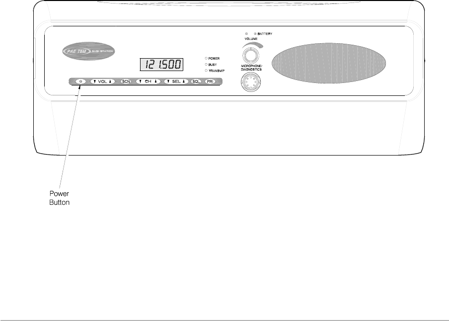
Power Button
(Figure 3, Item 16). The power button is used to switch on and off power to the radio circuits. When using
this switch, it must be pressed, and kept pressed for approximately one second until the front panel
display shows On or Off.
Note...
In addition to the front panel Power button, there is also a Power on/standby switch fitted on the
rear panel (see ‘Switching On and Off’ on page 20).
Warning!
Neither the Power button, nor the rear panel Power switch, isolates the input supply from the
equipment. Lethal voltages are still present in the base station's internal power supply. To
ensure safe working during maintenance, the ac and dc input supplies must be
disconnected from the base station.
T6M Base Station User Guide
Page 19
SWITCHING ON AND OFF
To switch on the base station:
(1) Ensure the Supply switch fitted to the base station's rear panel is set to on. Note that there is
no front panel indication as to whether the rear panel supply switch is on or set to standby.
(2) Press the front panel Power button for approximately one second until the display reads ‘On’.
Then release the button.
(3) Check that a warbling sound is heard for a few seconds and then a channel frequency is
displayed.
(4) The base station is now ready for use.
To switch off the base station, press the Power button until the display reads ‘Off’. Then release the
button. Note that this action removes power only from the radio module; power to other modules is
removed when the rear panel Supply switch is set to standby.
Warning!
Neither the Power button, nor the rear panel Power switch, isolates the input supply from the
equipment. Lethal voltages are still present in the base station's internal power supply. To
ensure safe working during maintenance, the ac and dc input supplies must be
disconnected from the base station.
Note ...
Always switch off the rear panel Power switch, and allow at least 10 seconds, before disconnecting
the ac and dc supply connectors. If this is not done, when next switched on the base station may
revert to previous channel and mode settings, and not those that were active immediately before
switching off.
T6M Base Station User Guide
Page 20
Base Station Front Panel Power Button Location

OPERATING THE BASE STATION IN NORMAL MODE
Operating the base station in Normal mode requires the following operations. Each operation is
explained in following paragraphs.
(1) Select Normal mode if not currently selected.
(2) Select the required channel frequency.
(3) Transmit using the fist microphone, and receive using the base station's internal
loudspeaker.
(4) Adjust, if necessary, the Squelch facility.
Selecting Normal Mode
Normal mode is active when neither Priority mode or Scan mode is selected. If Priority mode is selected,
the display shows ‘P’ every few seconds. If Scan mode is selected the display shows ‘Scn’ when
scanning, or the frequency when locked onto a busy channel. To select Normal mode if currently in
Priority or Scan mode:
qTo select Normal mode if currently in Priority mode, press the CH▲or CH▼button.
qTo select Normal mode if currently in Scan mode, press the SCN button.
Selecting a Channel Frequency
To select the required channel frequency, press the CH▲or CH▼button to scroll up or down through the
channel frequencies that are programmed into the base station. Release the button when the required
frequency is displayed.
In conjunction with the CH▲and CH▼buttons, the SEL▲and SEL▼buttons can be used to step
10 channels at a time.
Transmitting and Receiving
To key the transmitter press the fist microphone's PTT button. Check that the base station's Tx indicator
lights, and then speak clearly into the microphone.
Reception is heard through the base station's internal loudspeaker. The volume is adjusted using the
front panel's rotary Volume control that must be pushed in to switch on the loudspeaker. Users should
note that the VOL▲and VOL▼buttons do not adjust the volume. When a signal is received, the
base station's busy indicator lights if squelch is switched on; if squelch is switched off, the busy indicator
is permanently lit.
Switching and Adjusting the Squelch Facility
The base station has an adjustable squelch facility that can also be turned on and off. The squelch
facility, when correctly set, mutes unwanted background noise when no signals are being received.
During normal use of the base station the squelch facility should be switched on. After initially setting the
squelch level, there should be no reason to adjust it unless a problem is evident. The symptoms of an
incorrectly adjusted squelch level are:
qBackground noise is continuously, or intermittently heard when no signals are being received. If
this is the case, the setting is too low.
qWeak signals (signals below the squelch threshold) are not being received. If this is the case, the
setting is too high.
T6M Base Station User Guide
Page 21
These operating procedures assume the fist microphone that is normally supplied with the base station
is being used. As an alternative to the fist microphone, a microphone/headset can be used.

To Switch On the Squelch
To switch on the squelch facility:
(1) Press the SQL button.
(2) Check that the display shows an ‘S’ and the current level (a number between 1 and 20).
(3) Check that after a few seconds the display changes to show the currently selected channel
frequency. The squelch facility is now on.
To Switch Off the Squelch
To switch off the squelch facility:
(1) Press the SQL button.
(2) Check that the display shows an ‘S’ and the current level (a number between 1 and 20).
(3) Press the SQL button while the display is showing ‘S’ and the current level.
(4) Check that the display shows ‘S OFF’.
(5) Check that after a few seconds the display changes to show the currently selected channel
frequency. The squelch facility is now off.
To Adjust the Squelch Level
To adjust the squelch facility:
(1) Press the SQL button.
(2) Check that the display shows an ‘S’ and the current level (a number between 1 and 20).
(3) Press the VOL▲button to increase the squelch threshold, or the VOL▼button to decrease it.
The squelch should be set to the lowest threshold setting (a number between 1 and 20) that
eliminates background noise when no signal is being received.
(4) After the required setting is selected, press no more buttons and check that after a few
seconds the display changes to show the currently selected channel frequency. The squelch
facility is now set.
T6M Base Station User Guide
Page 22

OPERATING THE BASE STATION IN PRIORITY MODE
Priority mode allows faster access to frequently used channel frequencies. Up to 15 channel frequencies
can be programmed into the base station's priority list. The Priority facility must be programmed into the
base station before it can be selected, or used.
Operating the base station in Priority mode requires the following operations. Each operation is
explained in following paragraphs.
(1) Select Priority mode if not currently selected.
(2) Select the required channel frequency.
(3) Transmit using the fist microphone, and receive using the base station's internal
loudspeaker.
Selecting Priority Mode
Select Priority mode by pressing the PRI button. When selected, the display shows ‘P’ every few
seconds.
Selecting a Priority Channel Frequency
To select the required channel frequency, press the SEL▲or SEL▼button to scroll up or down through
the priority channel frequencies that are programmed into the base station. Release the button when the
required frequency is displayed.
Transmitting and Receiving
To transmit, key the transmitter by pressing the fist microphone's PTT button. Check that the base
station's Tx indicator lights, and then speak clearly into the microphone.
Reception is heard through the base station's internal loudspeaker. The volume is adjusted using the
front panel's rotary Volume control that must be pushed in to switch on the loudspeaker. Users should
note that the VOL▲and VOL▼buttons do not adjust the volume. When a signal is received, the
base station's busy indicator lights if squelch is switched on; if squelch is switched off, the busy indicator
is permanently lit. If the squelch facility requires adjusting, use the procedure ‘Switching and Adjusting
the Squelch Facility’ given on page 21.
T6M Base Station User Guide
Page 23

OPERATING THE BASE STATION IN SCAN MODE
In this mode the base station scans a number of pre-defined channel frequencies searching for a busy
one. When a busy channel is found, the base station provides reception on that channel. The Scan
facility must be programmed into the base station before it can be selected, or used.
Note …
A channel is defined as busy when it is receiving a signal strong enough to override the squelch
setting.
What happens after a busy channel is found depends on how the base station is programmed. There are
two possible options: Hold and Pause.
qIf Hold is programmed, the base station remains tuned to the busy channel until the CH▲button
is pressed to resume scanning.
qIf pause is programmed, the base station remains tuned to the busy channel for six seconds,
then automatically resumes scanning. If during the six seconds the radio is keyed, or the CH▲
button is pressed, the base station remains tuned to the busy channel; scanning does not
resume until the CH▲button is pressed again.
The base station can be programmed with up to 15 scan groups, each containing up to 15 channel
frequencies. Squelch is automatically switched on when scan mode is selected. Display blanking does
not operate in scan mode.
Selecting Scan Mode
To select Scan mode, press the SCN button. Check that the display shows Scn and a number between
1 and 15; the number corresponds to the currently selected scan group.
Selecting a Scan Group
When in Scan mode, the required scan group (a number between 1 and 15) is selected by pressing the
SEL▲or SEL▼button.
Transmitting and Receiving
To transmit when the scan function is on hold, or pause, key the transmitter by pressing the fist
microphone's PTT button. Check that the base station's Tx indicator lights, and then speak clearly into
the microphone.
Reception is heard through the base station's internal loudspeaker. The volume is adjusted using the
front panel's rotary Volume control that must be pushed in to switch on the loudspeaker. Users should
note that the VOL▲and VOL▼buttons do not adjust the volume. When a signal is received, the
base station's busy indicator lights if squelch is switched on; if squelch is switched off, the busy indicator
is permanently lit. If the squelch facility requires adjusting, use the procedure ‘Switching and Adjusting
the Squelch Facility’ given on page 21.
T6M Base Station User Guide
Page 24

PROGRAMMABLE OPTIONS
A number of options can be programmed into the radio's personality. The options are detailed in the
following paragraphs.
Display Blanking
Display blanking is applicable only to Normal and Priority modes; not Scan mode.
When display blanking is programmed, the radio's normal frequency display is replaced by a flashing bar
if the radio is not keyed during the display blanking time period (between 10 and 300 seconds).
Example,
Display blanking is programmed
Display blanking time is 60 seconds
Selected channel frequency is 121.500 MHz.
In this example, the display normally shows 121.500. If the transmitter is not keyed for
60 seconds, the display changes to a flashing bar.
Normal frequency display is reinstated when the radio is keyed, or when the VOL▲or VOL▼
button is pressed. Note that the display can be reinstated by pressing any other button, but
doing so may also alter other settings.
Warning Beeps
When programmed, the following conditions cause a warning beep to be heard when an attempt is made
to key the transmitter:
qThe radio has a fault that prevents transmissions.
qTrying to key the radio on a channel frequency that has the ‘Transmit Inhibit’ option set to ‘Always
Inhibit’.
qTrying to key the radio on a busy channel that has the ‘Inhibit if Busy’ option selected.
qImminent transmitter time out.
The volume of warning beeps is set in the personality (a value between 1 and 7); the front panel volume
control does not affect the beeps.
Key Beeps
This option, when programmed, produces a single beep whenever a button is pressed on the radio's
front panel. The volume of the beep is the same as the Warning beep.
T6M Base Station User Guide
Page 25

Transmit Inhibit
Any frequency programmed into the radio can be made ‘receive only’. To achieve this, the transmit
function on the channel is always inhibited, or the transmit facility can be inhibited only when the channel
is busy. If warning sounds have been set, a warning is heard when an attempt is made to key the
transmitter.
Maximum Transmit Time
A maximum continuous transmit time can be programmed into the radio's personality. The options are:
qNo limit.
qA limit that can be set between 30 and 300 seconds.
qIf a limit has been set, and warning sounds have been set, the radio produces warning beeps
10 seconds before the transmission time expires.
FRONT PANEL DISPLAY FOR 25 kHz AND 8.33 kHz CHANNEL SPACING
When selecting an 8.33 kHz channel frequency, the displayed frequency differs from the actual channel
frequency. Table 1 on page 27 shows the pattern used for 25 kHz and 8.33 kHz spaced channel
frequencies from 118.0000 MHz to 118.1916 MHz. The pattern is the same for any frequency within the
radio's frequency range. The display conforms to ICAO convention for 8.33 kHz operation.
Note that operation using 8.33 kHz channel spacing within the USA is not currently allowed under FCC
regulations.
T6M Base Station User Guide
Page 26

Table 1. Display for 25 kHz and 8.33 kHz Channel Spacing
Actual Frequency
(to 4 decimal places)
Channel
Spacing
Displayed Frequency
at Radio's Front Panel
118.0000 MHz
118.0000 MHz
118.0083 MHz
118.0166 MHz
118.0250 MHz
118.0250 MHz
118.0333 MHz
118.0416 MHz
118.0500 MHz
118.0500 MHz
118.0583 MHz
118.0666 MHz
118.0750 MHz
118.0750 MHz
118.0833 MHz
118.0916 MHz
118.1000 MHz
118.1000 MHz
118.1083 MHz
118.1166 MHz
118.1250 MHz
118.1250 MHz
118.1333 MHz
118.1416 MHz
118.1500 MHz
118.1500 MHz
118.1583 MHz
118.1666 MHz
118.1750 MHz
118.1750 MHz
118.1833 MHz
118.1916 MHz
25 kHz
8.33 kHz
8.33 kHz
8.33 kHz
25 kHz
8.33 kHz
8.33 kHz
8.33 kHz
25 kHz
8.33 kHz
8.33 kHz
8.33 kHz
25 kHz
8.33 kHz
8.33 kHz
8.33 kHz
25 kHz
8.33 kHz
8.33 kHz
8.33 kHz
25 kHz
8.33 kHz
8.33 kHz
8.33 kHz
25 kHz
8.33 kHz
8.33 kHz
8.33 kHz
25 kHz
8.33 kHz
8.33 kHz
8.33 kHz
118.000 MHz
118.005 MHz
118.010 MHz
118.015 MHz
118.025 MHz
118.030 MHz
118.035 MHz
118.040 MHz
118.050 MHz
118.055 MHz
118.060 MHz
118.065 MHz
118.075 MHz
118.080 MHz
118.085 MHz
118.090 MHz
118.100 MHz
118.105 MHz
118.110 MHz
118.115 MHz
118.125 MHz
118.130 MHz
118.135 MHz
118.140 MHz
118.150 MHz
118.155 MHz
118.160 MHz
118.165 MHz
118.175 MHz
118.180 MHz
118.185 MHz
118.190 MHz
T6M Base Station User Guide
Page 27

FAULT AND ERROR CODES
A number of fault and error codes are shown on the radio's display if an internal fault is detected. The
codes and their meaning are detailed in Table 2.
Table 2. Fault and Error Codes
Displayed
Fault or
Error Code
Title Meaning
F1 Synthesiser
failure
An internal fault on the synthesiser has been detected. Switch off the base
station and switch on again after a few minutes. If the fault persists, refer to
‘Maintenance’ in chapter 7.
F2 Unstable
output
An internal fault on the power amplifier has been detected. Switch off the base
station and switch on again after a few minutes. If the fault persists, refer to
‘Maintenance’ in chapter 7.
F4 Over
temperature
This condition may occur if the transmitter's duty cycle has been exceeded, or
when transmitting for long periods. The fault should clear if the radio is not
keyed and allowed to cool.
F8 High reflected
power Indicates a faulty antenna, antenna cable, or RF connector.
F16
F32
Low supply
voltage
High supply
voltage
These two faults indicate the internal power supply is faulty. Switch off the base
station and switch on again after a few minutes. If the fault persists, refer to
‘Maintenance’ in chapter 7.
Fault code F16 may be displayed when operating using the battery option and
the battery starts to run flat.
cErr Critical error
This error is displayed when the base station is initially switched on and no
personality information, or corrupted personality information, is detected. Refer
to ‘Programming the Base Station’ on page 37 and load a personality into the
base station.
T6M Base Station User Guide
Page 28

Chapter 4 - Installation
The instructions in this chapter should be followed, in the order given, to install the T6M base station.
INTRODUCTION
Warning. Lethal Voltages!
The instructions given in this chapter involve connecting lethal voltages to the
equipment. The instructions, therefore, must be carried out only by suitably qualified
personnel.
Warning. Unauthorized Modifications!
Changes, or modifications, made to this equipment that are not expressly approved by
Park Air Electronics, or parties authorized by Park Air Electronics, could void the user’s
authority to operate the equipment.
Warning. Antenna Radiation!
The antenna used with this radio equipment must be installed such that the resultant
radiated field strength is below 10 W/m²in areas normally accessible to personnel.
Installing the base station involves the following operations. Each operation is detailed in this chapter of
the user guide.
qUnpacking and checking the installation kit is complete.
qSetting (if necessary) internal links.
qSiting the base station.
qConnecting one, or more, RCUs to the base station (if required).
qConnecting an antenna.
qConnecting the base station chassis to earth.
qConnecting the microphone (or a microphone/headset).
qConnecting external facilities (if required) to the base station.
qConnecting a dc input supply (if required).
qConnecting a mains supply (if required).
qConnecting a PC, or laptop, so that the base station's personality can be modified.
T6M Base Station User Guide
Page 29
Before the base station is put into operational service, the required ‘personality’ information should be
programmed in. This information, includes channel frequencies and operating modes.
When a T6M base station is received from PAE, the personality is either:
qA personality programmed to the user's specific requirements.
or,
qA default personality that covers the 760 channels (25 kHz spaced) available in the VHF
aeronautical frequency band. No frequencies are allocated to the Priority list, and no scan
groups are set.
A programming kit is available from PAE. This allows a new personality to be programmed and downloaded.
The base station does not have to be removed from its installed position to download a new personality.
[Note that operation using 8.33 kHz channel spacing is not currently allowed within the USA.]

UNPACKING
When the base station is received from PAE, remove the packaging and check that the items listed in
Table 3 are included.
Table 3. Installation Materials
Item
Number
Description Quantity PAE
Part Number
1 Base station complete with enclosure 1 BT6MBS
2 Microphone terminated with 7-pin DIN plug 1 24-11030301
32 metres of mains cable terminated with a
3-pole socket (mates with AC input plug) 1 17-03000038S
4
15-way D-type plug (mates with Facilities
socket) comprising:
Plug connector
Cover
1
1
20-01150100
20D09150101
If ordered, a programming kit may be included. This kit, part number 70-T6MPMKIT, comprises:
qCD containing the software.
qBase station to PC connecting cable.
SETTING INTERNAL LINKS
Two internal links must be correctly set before the base station is used. Both links are factory set, but
may require checking if a replacement Interface module is fitted during the life of the base station. The
two links are:
qInterface module JP1. This link determines whether received audio, or transmitted and received
audio, is monitored through the internal loudspeaker (see ‘Local Monitoring of Transmitted
Audio’ on page 11).
qInterface module JP2. This link is set to correspond with the internal battery being fitted, or not
fitted.
When a base station is received from PAE, the links are normally set as per the user's requirements. If
there are any doubts, however, check the links as follows:
(1) Refer to Figure 5 that shows the base station in its enclosure. Remove and retain the six M4
pan head screws and associated washers that secure the equipment within the enclosure.
(2) Slide the equipment forward out of the enclosure. Refer to Figure 8 and identify the Interface
PCB. Refer to Figure 11 and identify links JP1 and JP2.
(3) Ensure the two links are set to the required positions.
(4) Slide the equipment back into its enclosure. Refit the six M4 securing screws and washers.
T6M Base Station User Guide
Page 30

SITING THE BASE STATION
Site the base station away from sources of heat and in a position that allows access to the rear panel
connectors and the On/Standby switch. If your base station is a rack mounted version, refer to Figure 2
and fit into an equipment rack either on telescopic slides, or fixed runners.
CONNECTING A T6M CONTROLLER TO THE BASE STATION
Up to four T6M Controllers can be connected to a base station. Users should refer to the T6M Controller
User Guide (part number 31-3600T6MC) for installation details.
The controllers are terminated on any of the base station's four RCU connectors. Figure 4 shows the
interconnections. The pin-out of the RCU connector is given in Table 4.
Table 4. RCU Connector Pin-Out
RCU Connector
Pin Number Signal
1 Ground
2 Line +
3 Line -
4 PTT (0 V active)
5 Not connected
6 Not connected
7 Not connected
8 Not connected
9 Not connected
CONNECTING AN ANTENNA
Warning. Antenna Radiation!
The antenna used with this radio equipment must be installed such that the resultant
radiated field strength is below 10 W/m²in areas normally accessible to personnel.
A suitable antenna must be connected to the base station's rear panel Antenna connector (see Figure 1).
An N-type plug should be used to connect the feeder cable; the connector is designed to accept UR67 or
RG213 coaxial cable that has an overall diameter of approximately 10 mm. Figure 12 shows the RF
cable to N-type connector termination. A suitable connector is PAE part number 19-01030301.
CONNECTING THE CHASSIS STUD TO EARTH
A chassis stud, marked is fitted to the base station's rear panel. When using the rack mounted
version of the base station, and in order not to compromise the equipment’s EMC the chassis stud must
be connected to the equipment rack or the system earth. The connection should be made using a single
tri-rated, green-and-yellow cable having a cross-sectional area of 2.5 mm2. The cable should have CSA
and UL1015 approval, and be connected to the chassis stud through an M6 eyelet.
T6M Base Station User Guide
Page 31

CONNECTING A MICROPHONE
The supplied fist microphone (Table 3, item 2) plugs directly into the base station's front panel
Microphone/Diagnostics connector.
The pin-out of the Microphone/Diagnostics connector is given in Table 5. Figure 4 shows the
connections used for the fist microphone circuit.
As an alternative to the fist microphone, a microphone/headset can be used. The ‘receiver audio monitor’
(Table 5 pin 5) should be used as the headset connection.
Table 5. Base Station Microphone/Diagnostics Socket Pin-Out
Pin Number Signal Input or Output Signal Level
1 Microphone ground Input 0 V
2 RS232 Tx Output RS232
3 Microphone PTT Input 0V=PTT
4 RS232 Rx Input RS232
5
Sidetone and
receiver audio
monitor
Output Maximum 1 V rms. Rout = 200 W
6 Microphone audio Input Passive microphone
7 Ground - 0 V
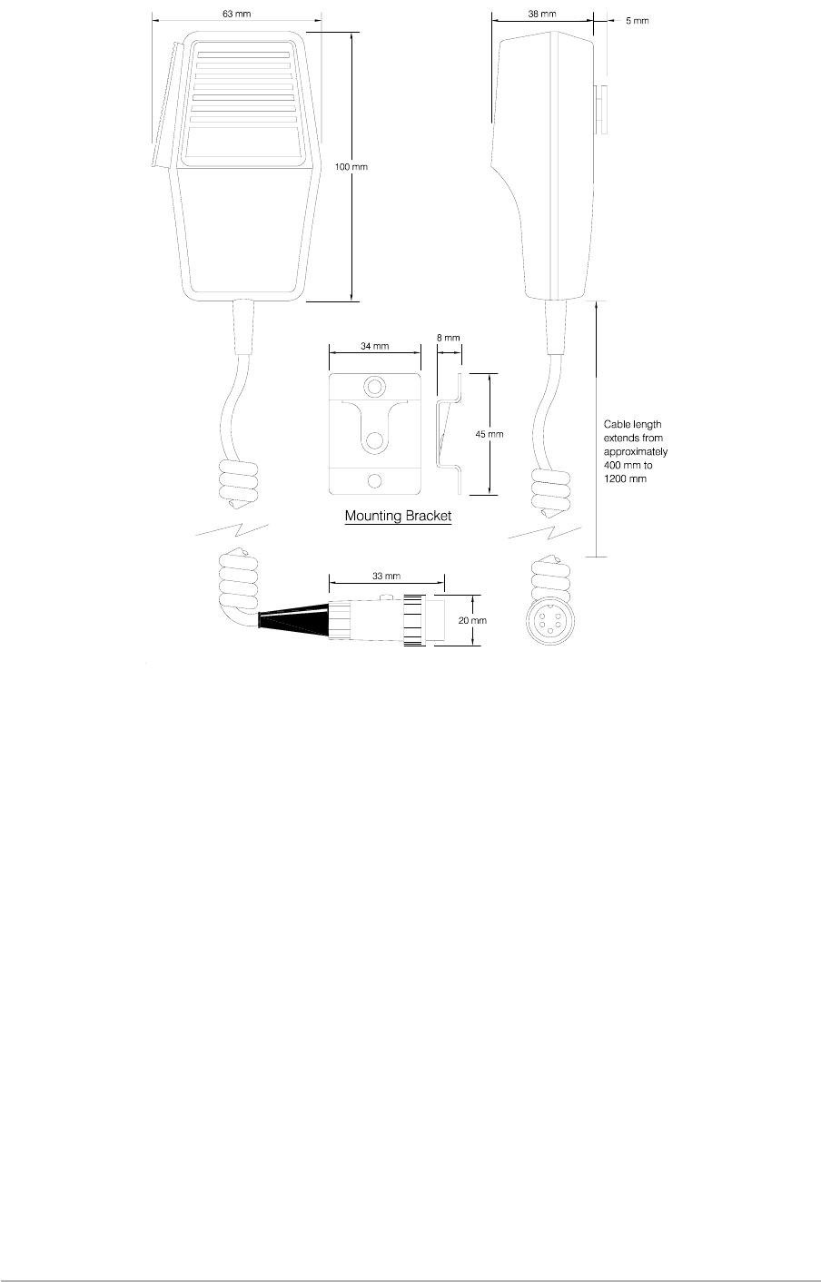
SECURING THE MICROPHONE BRACKET
A mounting bracket is supplied with each fist microphone (see illustration on the next page). The bracket
should be fitted to any convenient vertical surface, noting that the coiled microphone lead extends from
approximately 400 mm to 1200 mm.
Two screws secure the bracket to the chosen surface. The actual bracket should be used as a template
for drilling the two screw holes.
T6M Base Station User Guide
Page 32
CONNECTING EXTERNAL FACILITIES
Four optional external facilities can be connected to the base station. They are:
qAn audio output to drive an external tape recorder.
qTransmit audio, received audio, and PTT lines for use with a control desk.
qA transmit inhibit signal.
qAn audio operated squelch signal.
The external facilities are connected to the base station's rear panel Facilities connector. This connector
is detailed in Table 6. A 15-way D-type plug (Table 3, item 4) is provided to make the facilities
connections. Connection to the plug should be made using screened cable; the braid should be
connected to the plug's shell as shown in the illustration on page 35.
T6M Base Station User Guide
Page 33
Fist Microphone

Table 6. Base station Facilities Connector Pin-Out
Base Station's
Facilities
Connector Pin
Number
Signal Input or
Output Description
1 Ground - 0 V.
2
3
Tape +
Tape -
Output
A balanced 600 Wtwisted pair providing audio to drive
a tape recording system. The output level is 0 dBm
(sine wave on 600 W) for 85% modulation depth.
4Audio operated
squelch Output
0 V when received audio having a modulation depth
>20% is present. Open circuit at other times. This
signal can be used as an external ‘busy’ indication.
5
6
7
8
9
10
Control Desk Rx +
Control Desk Rx -
Control Desk Tx +
Control Desk Tx -
Control Desk PTT +
Control Desk PTT -
Output
Input
Input
A 6-wire system comprising two 600 Wtwisted pair
balanced lines for Rx and Tx audio, plus a line pair for
PTT.
The audio line levels are 0 dBm (sine wave on 600 W)
for 85% modulation depth. PTT can be activated either
by shorting together the PTT lines, or by phantom
keying on the Tx lines. Note that Control Desk PTT - is
internally connected to 0 V.
11
12
13
Not connected
Not connected
Not connected
--
14 External Tx inhibit Input When this line is connected to 0 V, the base station
cannot be keyed.
15 Ground - 0 V.
T6M Base Station User Guide
Page 34
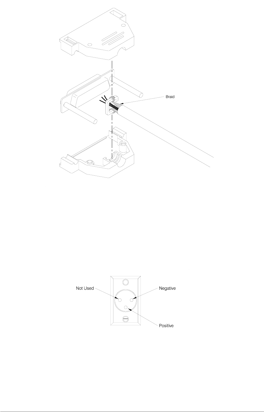
CONNECTING A DC INPUT SUPPLY
The base station can operate using a 12 to 15.5 V dc input supply, or it can be used as a backup to the
mains ac input. The DC Input connector fitted to the rear panel (see following illustration) is used for this
supply. Connection should be made using a free XLR socket; for example, PAE part number
20-01030106.
T6M Base Station User Guide
Page 35
DC Input Connector
Cable Braid Connection to D-Type's Shell
CONNECTING AN AC INPUT SUPPLY
An ac input supply must be connected to the base station using the supply connector provided (Table 3,
item 3). The free end of the cable should be terminated with a connector suitable for the local mains
supply.
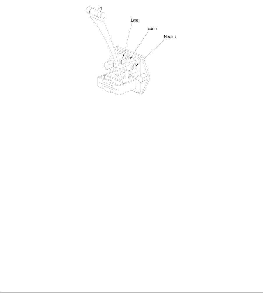
The T6M base station is a class 1 equipment. The ac supply cable must have a green-and-yellow
protective earthing conductor electrically connected to the protective earthing terminal of the equipment
connector, and the supply output connector.
The ac supply cable should be colour coded in accordance with the electrical appliance (colour code)
regulations for the UK. That is:
Line: Brown
Neutral: Blue
Earth: Green-and-yellow
Connections are shown below.
CONNECTING A PC TO THE BASE STATION
To modify the base station's personality, the microphone is disconnected from the
Microphone/Diagnostics connector and is replaced by an RS232 cable connected to a laptop, or PC. The
cable is part of the T6M programming kit, part number 70-T6MPMKIT. Figure 4 shows the connections
used for the RS232 cable.
T6M Base Station User Guide
Page 36
Base Station's Chassis AC Connector

Chapter 5 - Programming the Base Station
This chapter describes how a personality is compiled and then downloaded into the base station's
internal memory.
INTRODUCTION
During manufacture, the base station is programmed with a default personality, or with a personality as
per the user's requirements.
Note …
A personality is the programme that defines the radio's channel frequencies, operating modes,
and other options.
A new personality can be compiled and loaded into the radio at any time using the programming kit
(70-T6MPMKIT) available from PAE. The kit contains CD-ROM based software and a programming
lead. A laptop computer, or PC, must be available to compile the personality.
The following topics and procedures are detailed in this chapter:
qProgrammable options (see page 39).
qInstalling the programming software onto a laptop computer, or PC (see page 40).
qCreating a new personality (see page 40).
qSaving a personality (see page 44).
qOpening a saved personality (see page 45).
qLoading a personality into the radio (see page 45).
qReading a personality from the radio (see page 45).
qPrinting a personality report (see page 46).
T6M Base Station User Guide
Page 37

Table 7. Programming Options
Option Range Default Notes
Display blanking On or off Off See ‘Display Blanking’ on page 39.
Display blanking
time
10 to 300
seconds 60 seconds See ‘Display Blanking’ on page 39.
Maximum
transmit time
30 to 300
seconds, or
0 (unlimited)
180 seconds Limits the maximum continuous transmit time.
Hold on scan
mode On or off On See ‘Hold on Scan Mode’ on page 40.
Key beeps On or off On See ‘Key Beeps’ on page 39.
Warning beeps On or off On See ‘Warning Beeps’ on page 39.
Warning beep
volume 1 to 7 3 See ‘Warning Beeps’ on page 39.
Personality
description
46 character
alphanumeric
string
Empty string A free format text string that defines the radios
personality.
Use channel
strings Yes or no No
Defines whether channel frequencies are to include
descriptive strings. Selecting Yes for this option
reduces the maximum number of channels that can
be stored from 760 to 400.
Busy on time 0.1 to 5 seconds 0.5 seconds Squelch must be open for this time before a channel
is considered to be busy.
Offset channels On or off On When set to on, the radio scans for the strongest
frequency within a 25 kHz channel. Always set to On.
Frequency 118.000 to
136.9916 MHz
760 (25 kHz
spaced)
channels from
118.000 to
136.975 MHz
Enter this in ICAO format (see Table 1 on page 27);
this format automatically defines the frequency and
the bandwidth.
Priority channel Yes or no No Up to 15 channels can be defined as priority
channels.
Scan group 1to15ornot
assigned
No scan
groups
assigned
Up to 15 channels can be assigned to each of 15
scan groups. A channel frequency can be included in
more than one group.
Transmit
inhibited
Never inhibit
Always inhibit
Inhibit if busy
Never inhibit This option can be used to prevent the radio
transmitting on any particular channel frequency.
Identification
string
16 character
alphanumeric
string
Empty string A free format text string that describes the channel
frequency.
Base Enabled or
disabled Disabled Must be enabled for correct operation of the base
station.
T6M Base Station User Guide
Page 38

PROGRAMMABLE OPTIONS
A number of programmable options can be set in the base station's personality. These are listed in Table
7. The following paragraphs provide further explanation regarding display blanking, warning beeps, key
beeps, and hold on scan.
Display Blanking
Display blanking is applicable only to Normal and Priority modes; not Scan mode.
When display blanking is enabled, the radio's normal frequency display is replaced by a flashing bar if
the radio is not keyed during the display blanking time period.
Example,
Display blanking is enabled
Display blanking time is 60 seconds
Selected channel frequency is 121.500 MHz.
In this example, the display normally shows 121.500. If the transmitter is not keyed for
60 seconds, the display changes to a flashing bar.
Normal frequency display is reinstated when the radio is keyed, or when the VOL▲or VOL▼
button is pressed. Note that the display can be reinstated by pressing any other button, but
doing so may also alter radio settings.
Warning Beeps
When enabled, the following conditions cause a warning beep to be heard when an attempt is made to
key the transmitter:
qThe radio has a fault that prevents transmissions.
qTrying to key the radio on a channel frequency that has the ‘Transmit Inhibit’ option set to ‘Always
Inhibit’.
qTrying to key the radio on a busy channel that has the ‘Inhibit if Busy’ option selected.
qImminent transmitter time out.
The volume of warning beeps is set in the personality (a value between 1 and 7); the front panel volume
control does not affect the beeps.
Key Beeps
This option, when enabled, produces a single beep whenever a button is pressed on the radio's front
panel. The volume of the beep is the same as the Warning beep.
T6M Base Station User Guide
Page 39

Hold on Scan Mode
When in scan mode, what happens after a busy channel is found depends on how the radio is
programmed. There are two possible options: Hold and Pause.
qIf Hold is programmed, the radio remains tuned to the busy channel until the CH▲button is
pressed to resume scanning.
qIf pause is programmed, the radio remains tuned to the busy channel for six seconds, then
automatically resumes scanning. If during the six seconds the radio is keyed, or the CH▲button
is pressed, the radio remains tuned to the busy channel; scanning does not resume until the
CH▲button is pressed again.
INSTALLING THE PROGRAMMING SOFTWARE ONTO A LAPTOP, OR PC
The programming software is supplied on a CD-ROM. The software should be installed onto a laptop
computer, or PC, running Windows™ 95 or 98. To install the software:
(1) Insert the CD-ROM into the computer's CD drive.
(2) From Windows Explorer, select the CD-ROM drive, and run the programme called
Setup.exe.
(3) Follow the on-screen instructions. The programming files are stored in the directory
C:\Program Files\PAE unless a different directory is specified during installation. Icons, and
an uninstall programme are automatically created during installation.
CREATING A NEW PERSONALITY
This procedure creates a new personality for use by the radio. The personality includes all channel
frequencies, operating modes and programmable options that are required when the radio is in
operational use. When the personality has been compiled, it can be loaded into the radio's memory by
connecting the laptop (or PC) to the radio using the programming lead.
To create a new personality:
(1) At the laptop (or PC) run the PAE programmer software. Check that the General page (see
page 41) is displayed. If the Frequencies page is displayed, select the General tab.
(2) From the menu-bar select File then New. This action resets all options to the default value
and clears all entries, except one, in the frequency table.
T6M Base Station User Guide
Page 40
(3) Use Channel Strings.Decide if you wish to store descriptive text for any of the channel
frequencies that will be programmed. If you do, use the mouse to ensure the box is checked.
If you do not wish to use this facility, use the mouse to ensure the box is empty.
Notes …
If the Use Channel Strings facility is selected, the maximum number of channel
frequencies that can be stored is reduced from 760 to 400.
Descriptive text is shown on the frequency list within this programme; it is not displayed
at the radio.
T6M Base Station User Guide
Page 41
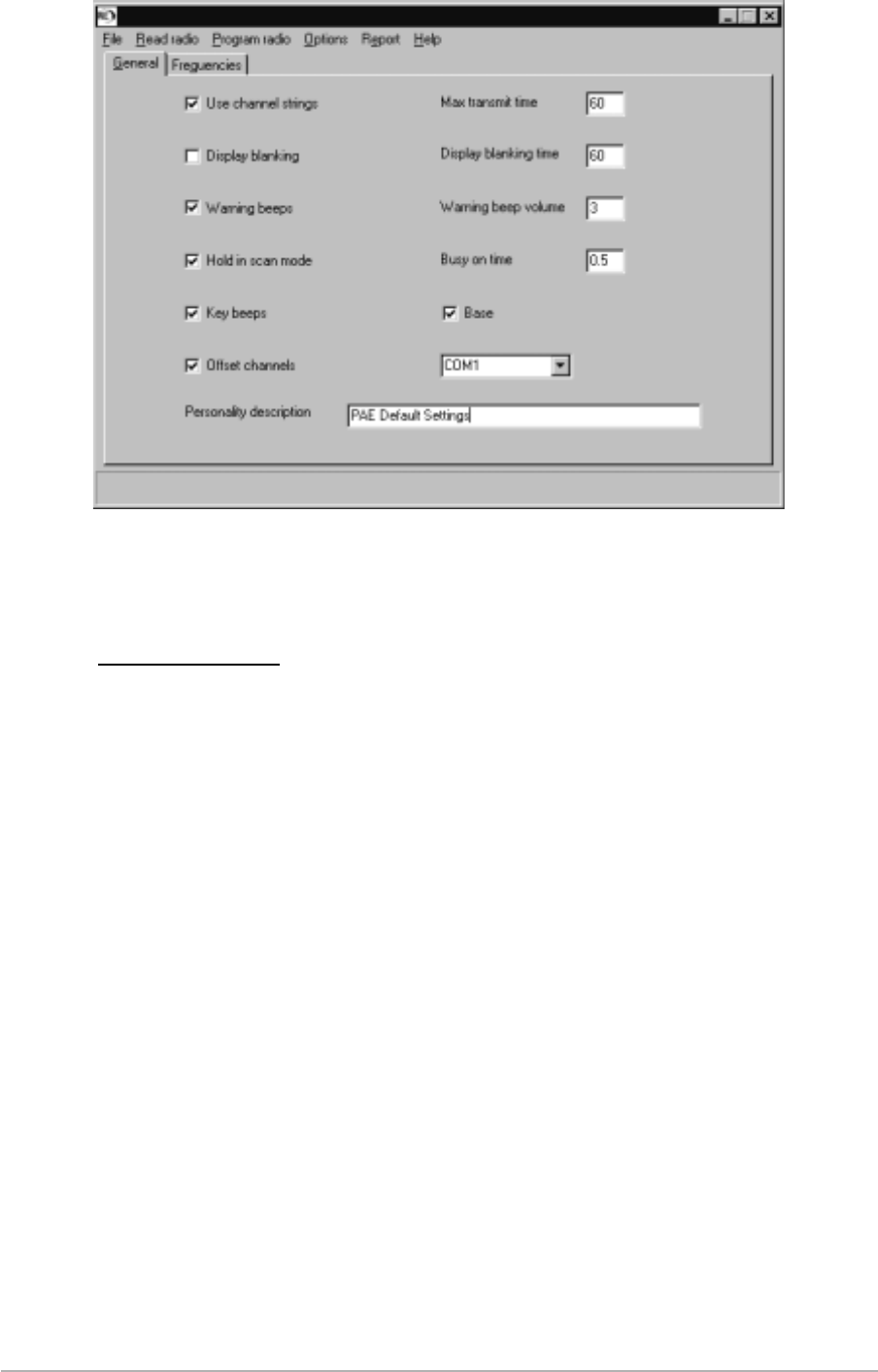
General Page
[Note that the status line at the bottom of the page displays help messages when the mouse pointer is placed
over a programmable option.]

(4) Maximum Transmit Time. This setting alters the maximum time the transmitter can be keyed.
Key in a value between 30 and 300 (seconds), or if no limit is required, enter 0. If a limit has
been set, and warning beeps are set, a warning is heard 10 seconds before the radio stops
transmitting.
(5) Display Blanking. Display blanking is described on page 39. If you require this facility use the
mouse to ensure the box is checked. If you do not wish to use this facility, use the mouse to
ensure the box is empty.
(6) Display Blanking Time. Enter a number between 10 and 300 (seconds). This is the time used
when the display blanking facility is selected to be active. Display blanking is described on
page 39.
(7) Warning Beeps. Warning beeps, as described on page 39, can be set to on or off. To set
them to on use the mouse to ensure the box is checked. To switch them off, ensure the box is
empty.
(8) Warning Beep Volume. The volume of warning beeps (if used) is represented by a figure
between 1 and 7. Enter the required value in the box.
(9) Hold in Scan Mode. This facility, which is only applicable to scan mode, is explained on page
40. When this box is checked, hold in scan mode is selected; if not checked, pause in scan
mode is selected.
(10) Busy On Time. This is the time a radio must be busy, when scan mode is selected, before the
radio holds, or is paused. Enter a value between 0.1 and 5 seconds.
(11) Key Beeps. When key beeps are enabled, a single beep is heard whenever a button is
pressed on the radio's front panel. The volume of the beep is the same as the Warning beep.
To enable this facility, check the box; to disable it, ensure the box is empty.
(12) Base. This check box must always display a tick. If it does not have a tick (unchecked), the
base station will not operate correctly.
(13) COM1 or COM2 Selection. Either Com port 1, or Com port 2, can be selected from the
drop-down menu. This selection determines which Com port on the laptop, or PC, the radio
must be connected to when transferring the personality to the radio.
(14) Offset Channels. The offset channels box should always be checked. This is one of the
radio's internal characteristics. It does not refer to offset frequency channels as defined by
ICAO.
(15) Personality Description. A unique name for the personality can be entered here (maximum
of 46 characters).
(16) When all fields on the General page are correctly configured, use the mouse and click on the
Frequencies tab. Check that the Frequencies page is shown (see next page).
T6M Base Station User Guide
Page 42

(17) When the Frequencies page is first selected there will be one default frequency shown. If this
frequency is required leave it as it is; if not, click in the frequency box and change the
frequency to that required.
Note …
Enter frequencies in ICAO format. The software recognizes the frequency and
appropriate channel spacing (Width). There is no need to manually enter the channel
spacing. The ICAO format is illustrated on page 27.
(18) If the frequency is required to be included in the Priority list, key in Y in the priority column. If
not required, ensure the column reads No.
(19) If the frequency is required to be included in a Scan group, enter the scan group number
(between 1 and 15) in the scan group column. If the frequency is to be included in more than
one scan group, enter the group numbers, separating each with a comma. Note that up to 15
frequencies can be included in each scan group.
(20) The Tx inhibit facility must now be set for the frequency. This facility determines when the
radio can transmit. Three options are allowed:
qNever. Key in N. This means the inhibit function is never enabled. The transmitter can be
keyed at any time, including at times when the channel is busy.
qBusy. Key in B. This means the inhibit function is enabled when the channel is busy. The
transmitter can however be keyed at all other times.
qAlways. Key in A. This means the inhibit function is always enabled. The channel is
therefore ‘receive only’ and the transmitter can never be keyed.
(21) If the Channel String option was selected from the General page, descriptive text (maximum
of 16 characters) can be keyed into the Identity column.
(22) One frequency channel entry is now complete. Further channels can be entered in the same
way by clicking on the Add channel box. To delete any entered channel, highlight the
frequency and click on the Delete channel box. When all the required frequency channels
have been entered, click on the ‘Verify and sort the table’ box. Any errors made when
compiling the frequencies page are automatically identified to the user.
T6M Base Station User Guide
Page 43
Frequencies Page
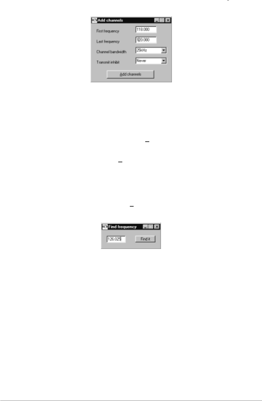
(23) As an alternative to manually entering frequency channels, and when many channels must
be entered, a range of frequencies can be entered. To do this, click on the Fill table box and
check that the Add channels sub-page is displayed.
(24) From the Add channels sub-page, enter the first and last frequencies in the required range.
From the drop-down menu, select the channel spacing (bandwidth); this can be 25 kHz,
8.33 kHz, or both. From the drop-down menu select the Transmit inhibit condition (Always,
Never, or Busy). When complete, click on the Add channels box. After the list of frequencies
is displayed on the Frequencies page, any individual frequency can be amended, for
example adding it to the priority list, as required. When all the required frequency channels
have been entered, click on the ‘Verify and sort the table’ box. Any errors made when
compiling the frequencies page are automatically identified to the user.
(25) When a lot of frequencies are entered and it is required to amend the entry, for example
adding it to the priority list, a quick method of displaying the frequency is by clicking on the
Find channel box. This displays the Find frequency sub-page. Enter the frequency on the
sub-page and click on Find it. The frequency is then displayed on the Frequencies page.
After amending the entry, click on the ‘Verify and sort the table’ box. Any errors made are
automatically identified to the user.
SAVING A PERSONALITY
When a personality has been compiled, it should be saved. To do this:
(1) From the programming menu, select File, then Save As.
(2) When the Save As window is displayed enter a file name for the personality. The file name
must have the extension .PER.
(3) Click on Save to store the personality. Before the save process, the personality is
automatically checked for any errors. If errors do exist they are highlighted to the user.
(4) If the save is successful, the file name appears at the top of the programming window. At any
time, the personality can be edited and saved using the same filename.
T6M Base Station User Guide
Page 44
Add Channels Sub-Page
Find Frequency Sub-Page

OPENING A SAVED PERSONALITY
To open a previously saved personality:
(1) From the programming menu, select File, then Open.
(2) Select one of the personality files and click on Open.
LOADING A PERSONALITY INTO THE RADIO
Use the following procedure to load a personality into the radio:
(1) Switch off the laptop (or PC) and the radio.
(2) At the radio, disconnect the microphone from the front panel. Replace it with the
programming lead.
(3) Connect the other end of the programming lead to the laptop's (or PC's) Com port 1 or Com
port 2. Note that the appropriate port is set in the personality. The connected port must match
that stated in the personality. Check, and amend if necessary.
(4) Switch on the laptop and then the base station (laptop must be switched on before the base
station). At the base station check that Pr is shown on the front panel display.
(5) Ensure the programming software is running and display the required personality on screen.
(6) From the programming menu-bar select ‘Program radio’ and then ‘Personality’.
The programmer automatically verifies the personality is valid and downloads it to the radio. If it is not
valid the nature of the error will be displayed. The progress of the programming operation is displayed on
the status line at the bottom of the programming screen.
When programming is complete, switch off the radio and laptop, remove the programming lead,
reconnect the radio's microphone and restore the equipment ready for operational use.
READING A PERSONALITY FROM THE RADIO
To read a personality from the radio:
(1) Switch off the laptop (or PC) and the radio.
(2) At the radio, disconnect the microphone from the front panel. Replace it with the
programming lead.
(3) Connect the other end of the programming lead to the laptop's (or PC's) Com port 1 or Com
port 2. Note that the appropriate port is set in the personality. The connected port must match
that stated in the personality. Check, and amend if necessary.
(4) Switch on the laptop and then the base station (laptop must be switched on before the base
station). At the base station check that Pr is shown on the front panel display.
(5) Ensure the programming software is running.
(6) From the programming menu-bar select ‘Read radio’ and then ‘Personality’.
The progress of the read operation is displayed on the status line at the bottom of the programming
screen.
When complete, switch off the radio and laptop, remove the programming lead, reconnect the radio's
microphone and restore the equipment ready for operational use.
T6M Base Station User Guide
Page 45

PRINTING A PERSONALITY REPORT
A personality can be printed as follows:
(1) From the programming menu, select Report, then Generate.
(2) The programmer automatically verifies the personality is valid. If it is not valid the nature of
the error will be displayed.
(3) A textual representation of the personality is displayed using the Windows Notepad
programme. When Notepad displays the personality it can be saved as a text file, or printed.
Previously saved Notepad files containing personalities can be retrieved by selecting Report, then Open
from the menu-bar.
T6M Base Station User Guide
Page 46

Chapter 6 - Spares
INTRODUCTION
The base station is manufactured using surface mount technology. Because of this, and the specialist
test equipment required to set up the circuits, spares are limited to modules and components as listed
below.
LIST OF SPARES
The following spares are available from PAE. When ordering, the part number should always be
quoted.
T6M base station (complete) BT6MBS
Radio module 25F00000T6M
Interface module 68-T6MBS635
Switched mode power supply unit 69F07150135S
Reservoir capacitor 33000 mF 63 V 14-06339200
Fan, dc, 12 V operation 69F12120612
Loudspeaker, 4 W, 4 ohm 04F05509034
Fuse 5 A anti-surge, 20 mm
(located in ac connector) 29F01140102S
Fuse 15 A, size 0 (dc input) 29-01350201
Microphone 24-11030301
Optional battery 06F30012300
Programming kit (includes
CD-ROM and programming lead) 70-T6MPMKIT
T6M Base Station User Guide
Page 47

Intentionally Blank
T6M Base Station User Guide
Page 48

Chapter 7 - Maintenance
This chapter details the scheduled maintenance required by the T6M base station.
It also provides fault finding guidance.
SCHEDULED MAINTENANCE
Scheduled maintenance to the T6M base station involves the following checks:
(1) Transmit power and frequency accuracy test. This check should be carried out annually.
(2) Receiver sensitivity check. This check should be carried out annually.
(3) Battery replacement (applicable only to base stations fitted with the internal battery option).
The life of the battery depends upon its usage; refer to ‘Battery Replacement’ on page 52.
Test Equipment Required
The test equipment necessary to complete the scheduled maintenance is listed in Table 8.
Table 8. List of test equipment
Item Description
1 Through-line wattmeter.
2 20 dB attenuator (>15 W continuous power rating).
3 VHF Frequency counter.
4 RF signal generator.
5 AF wattmeter.
6 Test lead for connecting the base station to the AF wattmeter. [See next heading.]
Test Lead
The test lead (Table 8, item 6) connects the base station to the AF wattmeter during receiver sensitivity
tests. The lead connections are detailed in Table 9.
Table 9. Test Lead Connections
7-Pin DIN Plug
(connects to base station's
Microphone connector)
AF Wattmeter Connector
Pin 5, receiver audio monitor Input
Pin 7, earth 0 V
T6M Base Station User Guide
Page 49
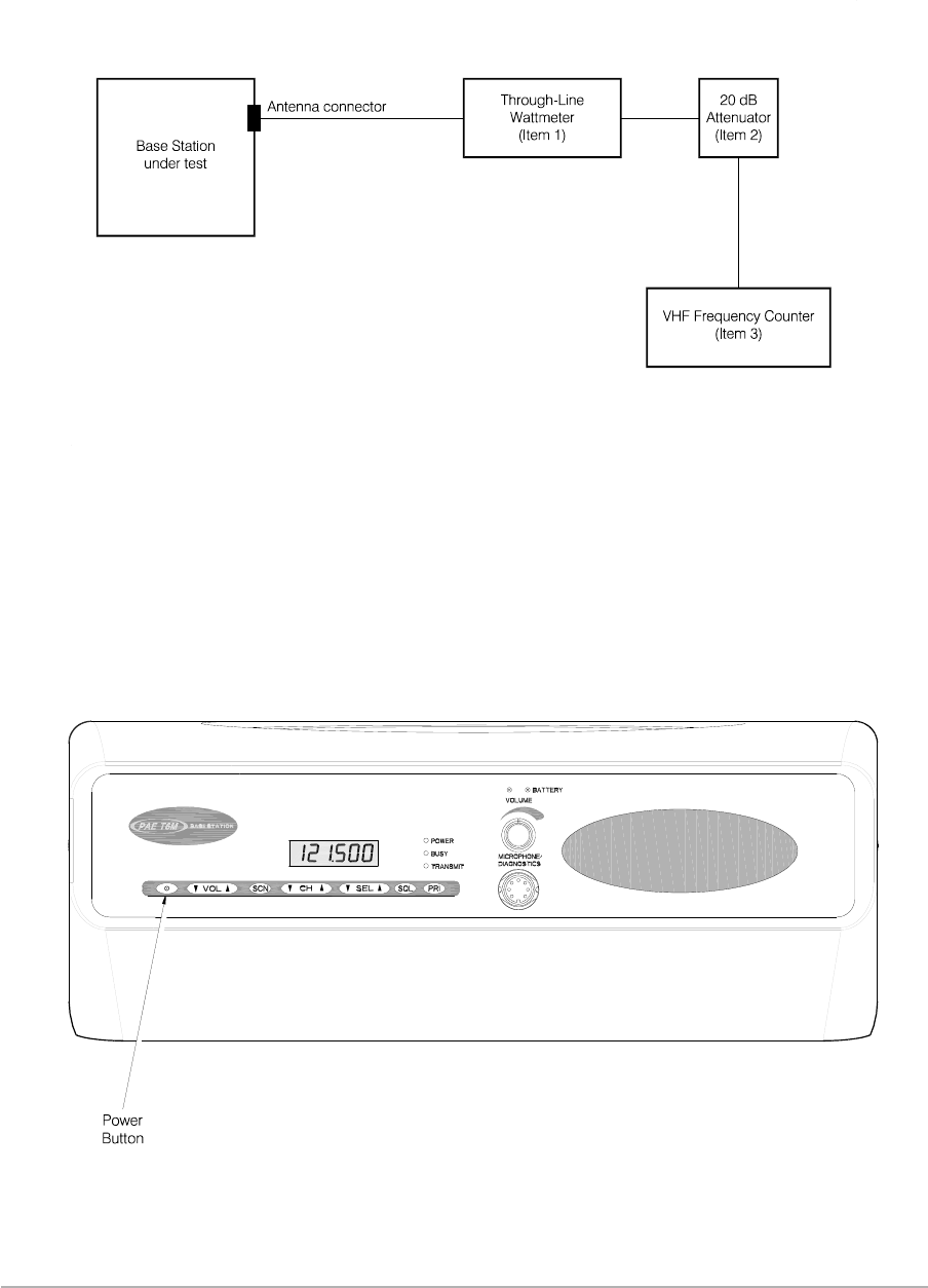
Transmit Power and Frequency Accuracy Test
To check the base station's transmit power, and the accuracy of the carrier frequency, carry out the
following procedure:
(1) Isolate power from the base station and connect the test equipment as shown below. Ensure
the wattmeter is switched to forward power.
(2) Reconnect the power and ensure the base station's rear panel Power switch is set to on.
(3) To enter Test mode switch on the base station by pressing, and keeping pressed, the front
panel Power button. Without releasing the Power button, press and release the SQL button,
then the SCN button, and finally the PRI button. Release the Power button.
T6M Base Station User Guide
Page 50
Transmit Power and Frequency Accuracy Test - Test Equipment Connection
Base Station Front Panel Power Button Location

(4) Check that the display shows tESt and after a few seconds it changes to show the current
power level setting (a number between 1 and 240 representing approximately 6 to 12 watts).
(5) Press the SQL button to select the test frequency 127.500 MHz. The test frequency is
displayed for a couple of seconds and the display then reverts to the power setting.
Note …
Using the SQL key to select a test frequency always selects a 25 kHz spaced channel.
Squelch is automatically switched off in Test mode.
(6) Key the transmitter and note the wattmeter's reading.
(7) With the transmitter de-keyed, use the CHsand CHtbuttons to increment or decrement
the power setting in steps of 1. Alternatively, use the SELsand SELtbuttons to increment
or decrement the power setting in steps of 10. Then key the transmitter and note the
wattmeter's reading. The power setting cannot be adjusted when the transmitter is
keyed. Adjust the power output until the required power is set (nominally 8 watts).
Note …
The transmit indicator lights when the transmitter is keyed. If a fault is detected, the
indicator does not light. No fault codes, however, are displayed in Test mode.
(8) Key the transmitter and check that the frequency counter reads between 127.499808 and
127.500192 MHz.
(9) To save the new power setting in the base station's memory, press and keep pressed the
front panel Power button. Without releasing the Power button, press and release the PRI
button, then the SCN button, and finally the SQL button.
(10) When the new setting is saved, the display shows ‘S’ and two short beeps are heard.
Release the Power button.
(11) To switch off without saving the new power setting, press and release the Power button. The
display shows nS and a single long tone is heard.
(12) Enter test mode again by pressing, and keeping pressed, the front panel Power button.
Without releasing the Power button, press and release the SQL button, then the SCN button,
and finally the PRI button. Release the Power button.
(13) Check that the display shows tESt and after a few seconds it changes to show the current
power level setting.
(14) Press the SQL button to select the test frequency 118.000 MHz.
(15) Key the transmitter and check that the wattmeter reads between 6 and 12 watts. Check that
the frequency counter reads between 117.999823 and 118.000177 MHz.
(16) Press the SQL button to select the test frequency 136.975 MHz.
(17) Key the transmitter and check that the wattmeter reads between 6 and 12 watts. Check that
the frequency counter reads between 136.974745 and 136.975205 MHz.
(18) On completion, switch off the base station and disconnect the test equipment. Restore the
base station ready for operational use.
T6M Base Station User Guide
Page 51

Receiver Sensitivity Check
To check the base station's receiver sensitivity carry out the following procedure:
(1) Isolate power from the base station and connect the test equipment as shown below.
(2) Reconnect the power and ensure the base station's rear panel Power switch is set to on.
(3) Adjust the signal generator to operate at 118.000 MHz with an RF level of -100 dBm and a
1 kHz tone modulated at 30%.
(4) At the base station's front panel press the squelch (SQL) button. Check that the display
shows an ‘S’ and a number between 1 and 20. This number is the squelch level setting.
(5) Adjust the squelch level, by pressing the VOLsand VOLtbuttons, until the display shows a
level of 2.
(6) Adjust the volume control until a reference reading (approximately mid-scale) is shown in the
AF wattmeter. Note the reading in dB.
(7) Set the signal generator's modulation to off.
(8) Increase the sensitivity of the AF wattmeter until a reading is obtained. Note the reading in
dB.
(9) Check that the difference in readings noted in steps (6) and (8) are not less than 10 dB.
(10) Repeat steps (3) to (9) for test frequencies of 127.500 MHz and 136.975 MHz.
(11) On completion, switch off the base station and disconnect the test equipment. Restore the
base station ready for operational use.
Battery Replacement
An optional battery can be fitted to act as a backup supply if the mains supply fails. The lead acid battery
is fitted in the position shown in Figure 8.
The battery should be replaced after a period of time that depends on usage. Table 10 details the
replacement period according to usage.
T6M Base Station User Guide
Page 52
Receiver Sensitivity Test - Test Equipment Connection

Table 10. Battery Replacement
Battery Usage Replacement After
Not used. Battery kept fully charged. 8 years.
Battery used until fully discharged (that is, 2 hours use
at 10% duty cycle). 60 discharges.
Battery used for approximately 1 hour at 10% duty
cycle (50% discharge). 120 partial discharges.
Battery used for approximately 30 minutes at 10% duty
cycle (25% discharge). 240 partial discharges.
Battery used for approximately 10 minutes at 10% duty
cycle (10% discharge). 600 partial discharges.
FAULT FINDING
Warning!
Neither the Power button, nor the rear panel Power switch, isolates the input supply from the
equipment. Lethal voltages are still present in the base station's internal power supply. To
ensure safe working during maintenance, the ac and dc input supplies must be
disconnected from the base station.
The T6M base station contains the following replaceable modules (see Figures 6, 7, and 8):
qA T6M radio module (a self-contained transceiver).
qAn interface module that interconnects the various external signals, and the power supplies, to
the radio module.
qA switched mode power supply (SMPS).
The base station's modules are manufactured using surface mount technology. Because of this, and the
specialist test equipment required to set up the circuits, spares are limited to modules and components
as listed on page 47.
The following table gives help in fault diagnosis.
T6M Base Station User Guide
Page 53

Table 11. Fault Diagnosis
Symptom Check
No front panel indicators lit. Check input supplies.
Check ac supply input fuse (located in rear panel ac
connector) and dc supply fuse.
Check output of switched mode power supply (SMPS). This
should be +15.6 V dc (wrt 0 V) at TP21 (located next to CN10)
of the Interface PCB (see Figures 7 and 11). If the SMPS is
suspect, remove it from the base station and test it on the
workbench ensuring a load is connected across its output.
Fault, or error code displayed at front panel. Fault and error codes are displayed on the front panel to
indicate faults detected by the radio module. These codes are
detailed in Table 12.
Transmit function not operating correctly.
Transmit inhibit indicator flashing.
External transmit inhibit facility is deliberately or inadvertently
enabled. This facility is enabled when pin 14 on the base
station's Facilities connector is grounded (see Table 6 on
page 34.
Transmit function not operating correctly. No
fault code displayed.
Complete the ‘Transmit Power and Frequency Accuracy Test’
detailed on page 50. If the test fails, check for any obvious
problems such as a faulty PTT switch. Note also that the
signal from the microphone connector passes through the
Interface module before being connected to the radio module
(see Figures 6 and 7). If the signals are correct at the radio
input, then change the radio module.
Receive function not operating correctly. No
fault code displayed.
If some signals are not being received, refer to the operating
instructions and check the squelch level is correctly set.
Complete the ‘Receiver Sensitivity Check’ on page 52. If the
test fails, use Figures 6 and 7 to determine where the fault lies.
For example, audio out of the radio module can be monitored
at the Interface module connector CN8 pins 3 and 7. The
Interface module's audio output to the loudspeaker can then
be monitored on CN7 pins 13 and 14. Using Figures 6 and 7
should enable the fault to be diagnosed to either the radio
module, or the Interface PCB.
If the ‘Receiver Sensitivity Check’ is OK, the fault is probably
in the antenna system.
T6M Base Station User Guide
Page 54

Table 12. Fault and Error Codes
Displayed
Fault or
Error Code
Title Meaning
F1 Synthesiser
failure
An internal fault on the synthesiser has been detected. Switch off the base
station and switch on again after a few minutes. If the fault persists, replace the
radio module with a serviceable spare.
F2 Unstable
output
An internal fault on the power amplifier has been detected. Switch off the base
station and switch on again after a few minutes. If the fault persists, replace the
radio module with a serviceable spare.
F4 Over
temperature
This condition may occur if the transmitter's duty cycle has been exceeded, or
when transmitting for long periods. The fault should clear if the radio is not
keyed and allowed to cool.
F8 High reflected
power
Indicates a faulty antenna, antenna cable, or RF connector. Check the antenna
circuit and replace any unserviceable component.
F16
F32
Low supply
voltage
High supply
voltage
These two faults indicate the internal power supply is faulty. Switch off the base
station and switch on again after a few minutes. If the fault persists, replace the
power supply module with a serviceable spare.
Fault code F16 may be displayed when operating using the battery option and
the battery starts to run flat.
cErr Critical error
This error is displayed when the base station is initially switched on and no
personality information, or corrupted personality information, is detected. Refer
to ‘Programming the Base Station’ on page 37 and load a personality into the
base station.
REPLACING MODULES
If it is necessary to remove a module, refer to the following figures for guidance:
qFigure 8 Base station layout diagram
qFigure 9 Radio module and PSU removal
qFigure 10 Interface PCB and reservoir capacitor removal.
Modules are accessed as follows:
(1) Refer to Figure 5 that shows the base station in its enclosure. Remove and retain the six M4
pan head screws and associated washers that secure the equipment within the enclosure.
(2) Slide the equipment out of the enclosure.
Note that when fitting a new Interface module, two links must be correctly set. Refer to ‘Setting Internal
Links’ on page 30.
T6M Base Station User Guide
Page 55

Intentionally Blank
T6M Base Station User Guide
Page 56

Chapter 8 - Figures
This chapter contains the A3 size figures referred to throughout this user guide.
1 Front and rear layout
2 Rack mounted version
3 Key to front panel controls
4 External connection diagram
5 Enclosure securing detail
6 Base station block diagram
7 Base station interconnection diagram
8 Base station layout diagram
9 Radio module and PSU removal
10 Interface PCB and reservoir capacitor removal
11 Interface PCB layout diagram
12 Cable termination at the N-type connector
T6M Base Station User Guide
Page 57

Intentionally Blank
T6M Base Station User Guide
Page 58
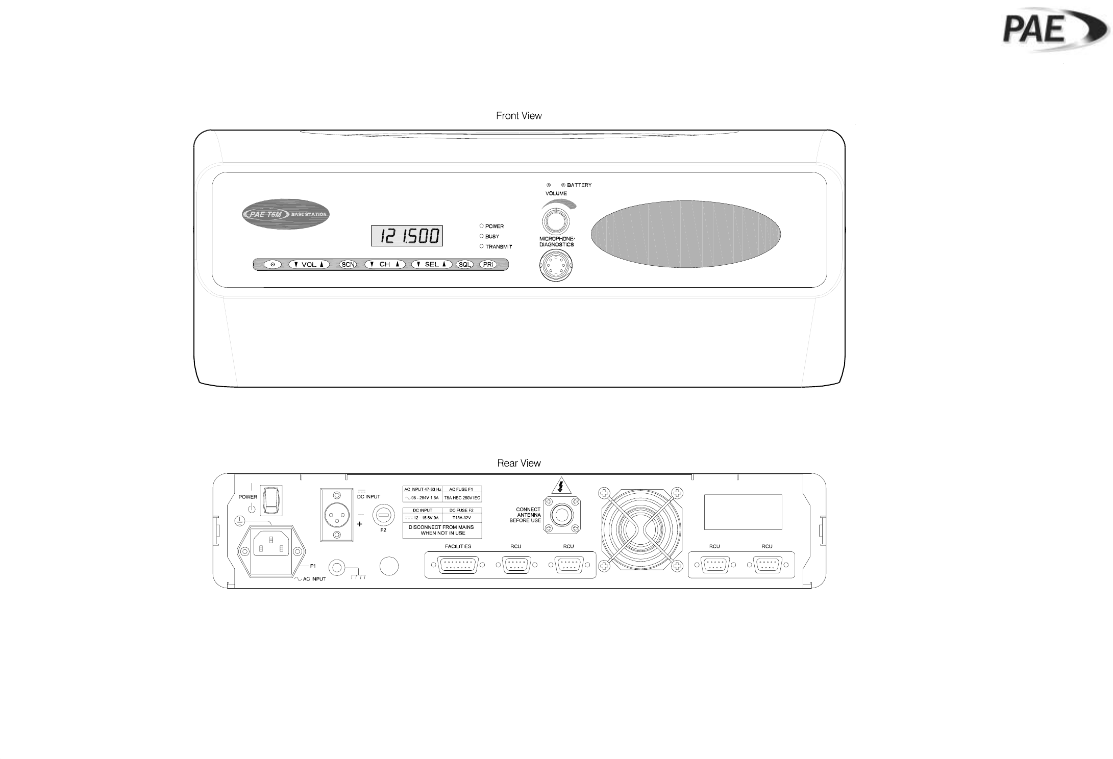
BT6MBS-01
Front and Rear Layout
Figure 1
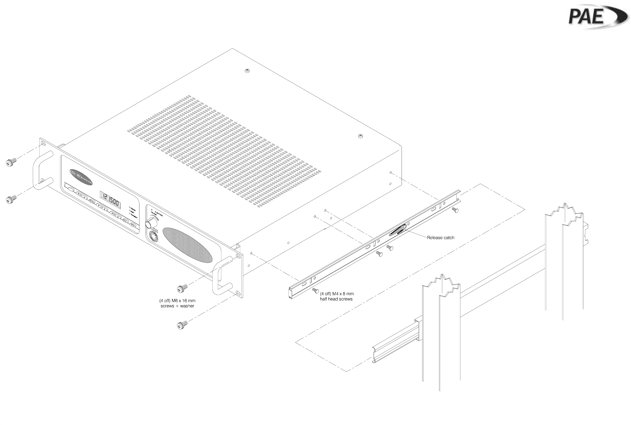
BT6MBS-13
Rack Mounted Version
Figure 2
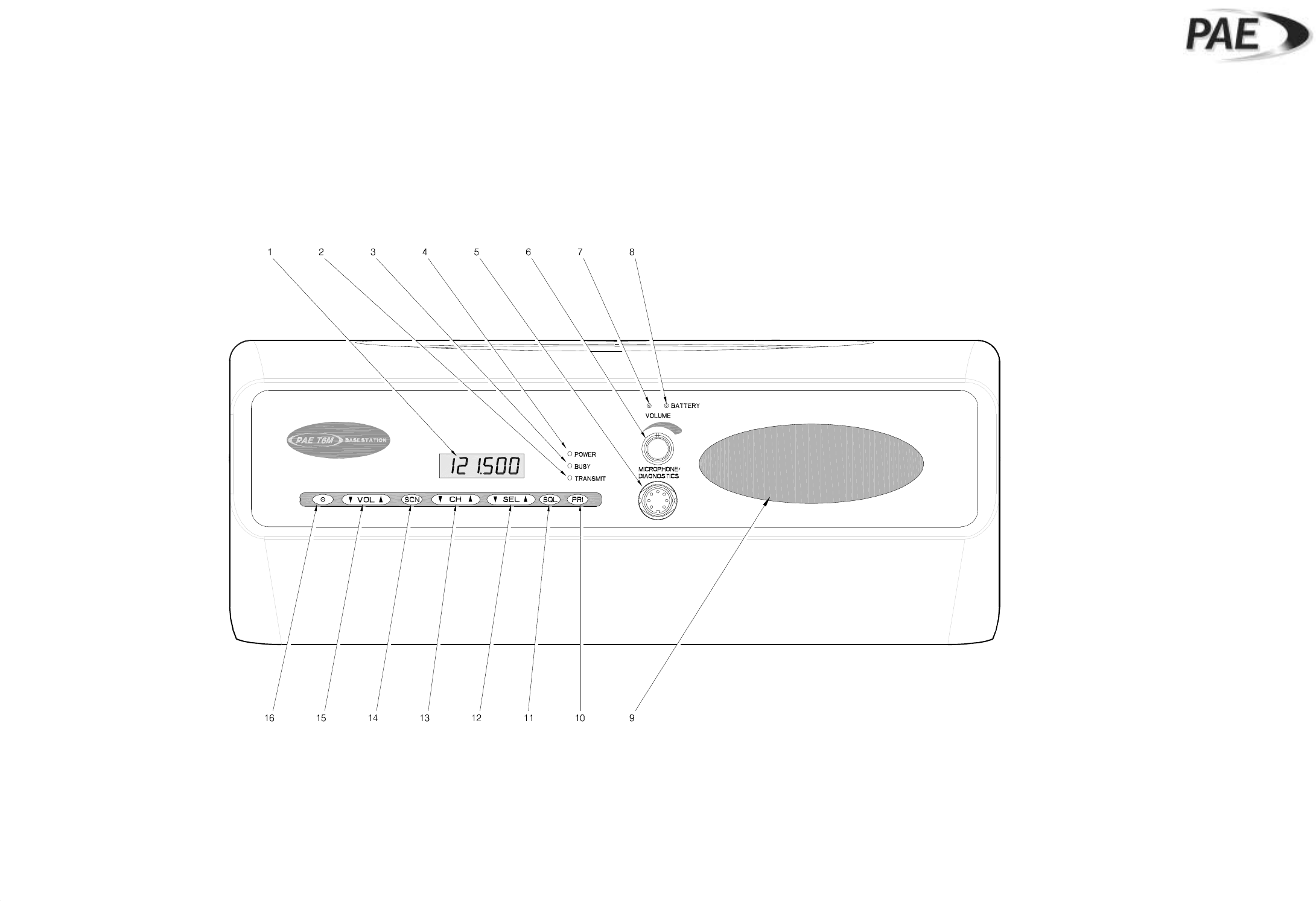
GA10642 Iss. 1
Key to Front Panel Controls
Figure 3
For description of controls, see text in chapter 3.
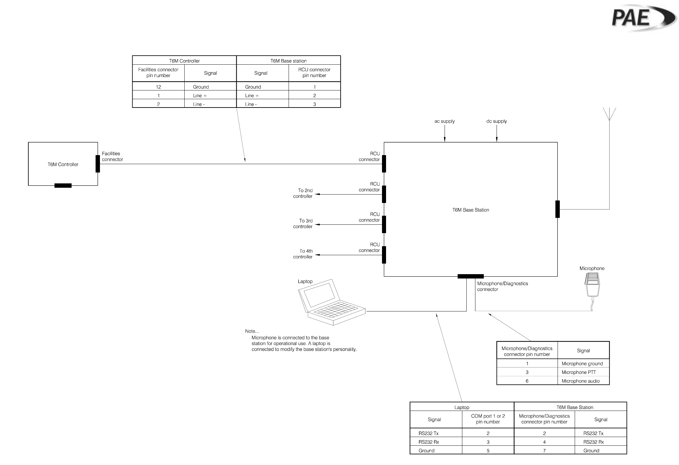
BT6MBS-11
External Connection Diagram
Figure 4
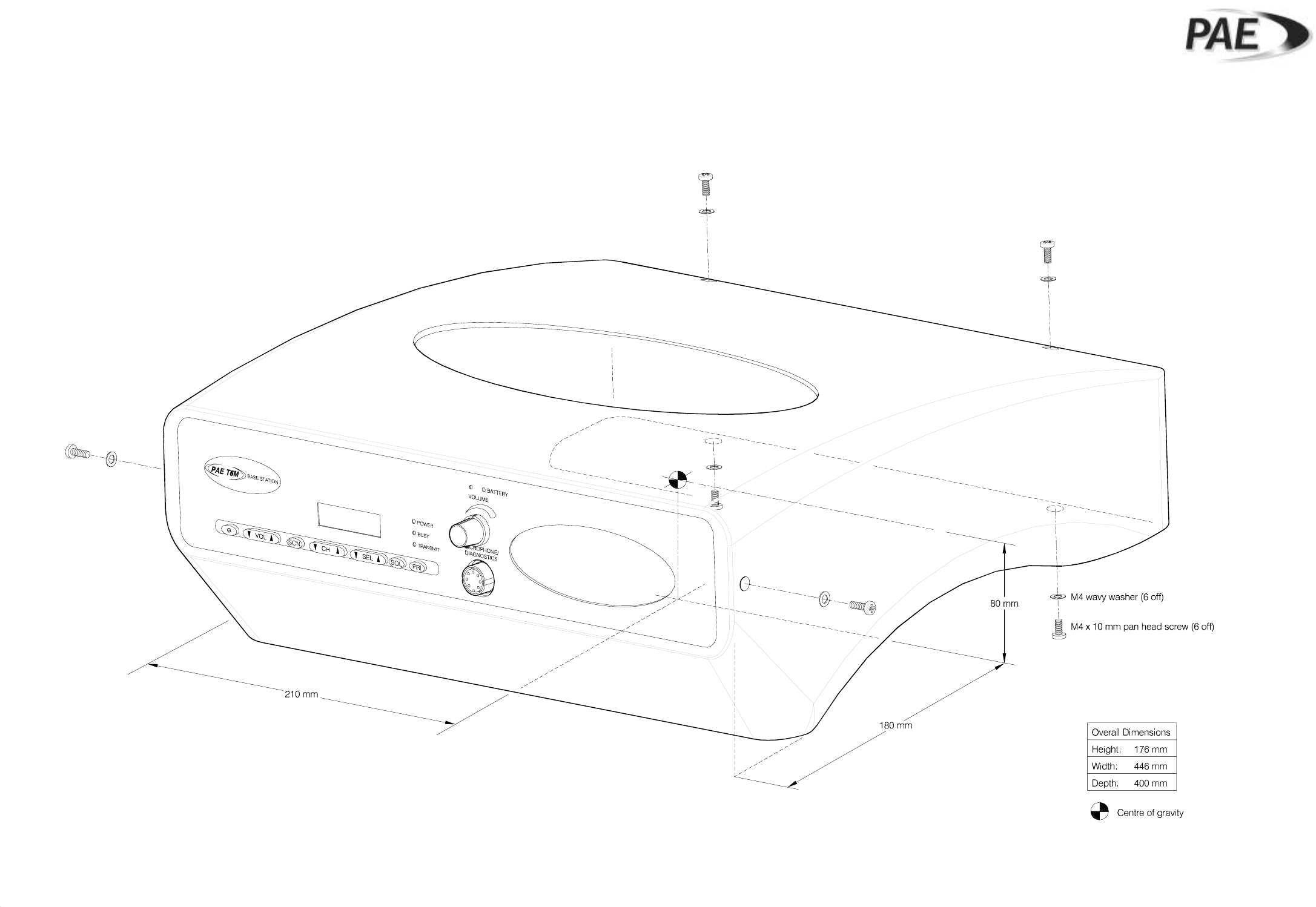
BT6MBS-10
Enclosure Securing Detail
Figure 5
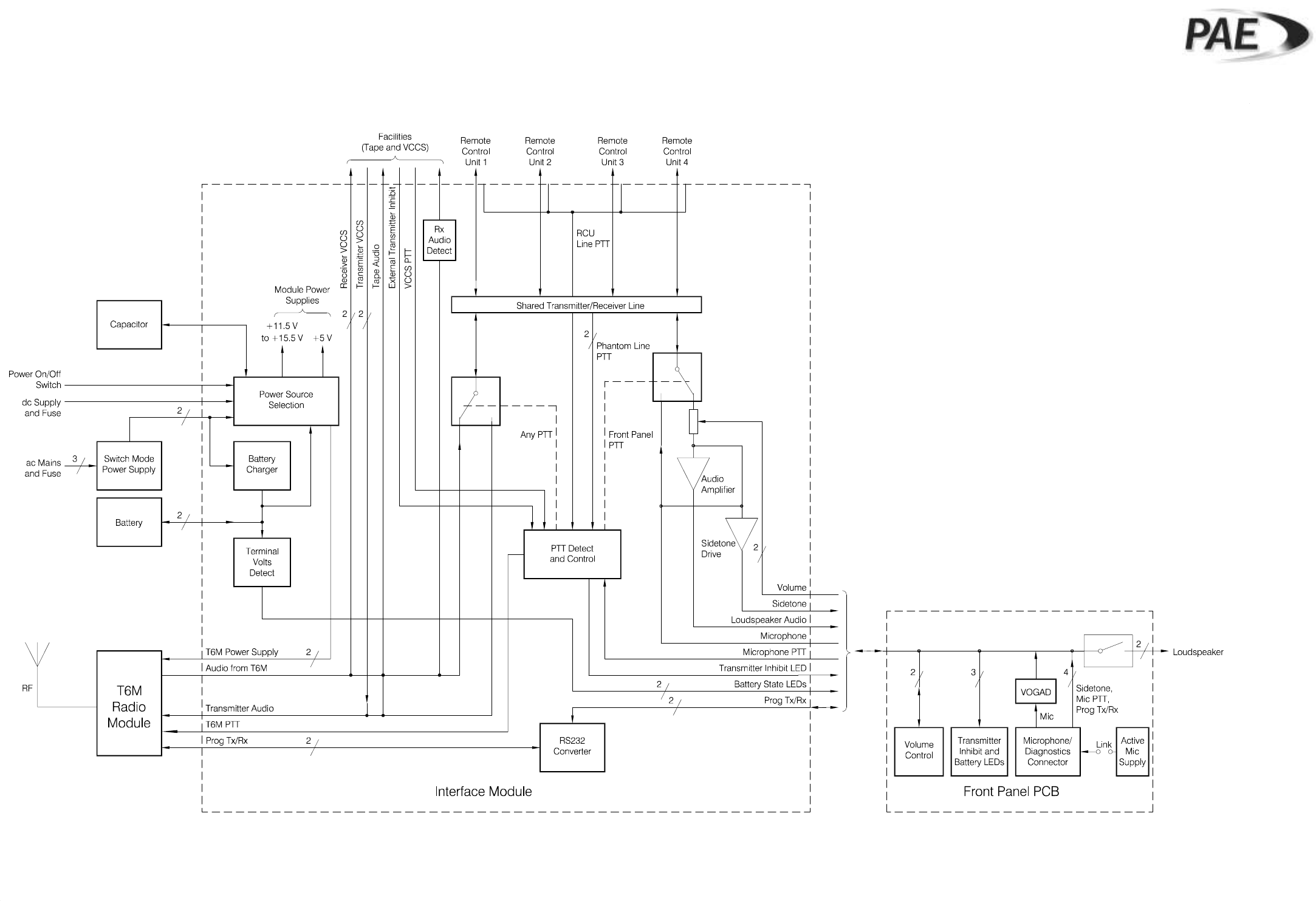
Base Station Block Diagram
Figure 6
GA10547 Iss. 3
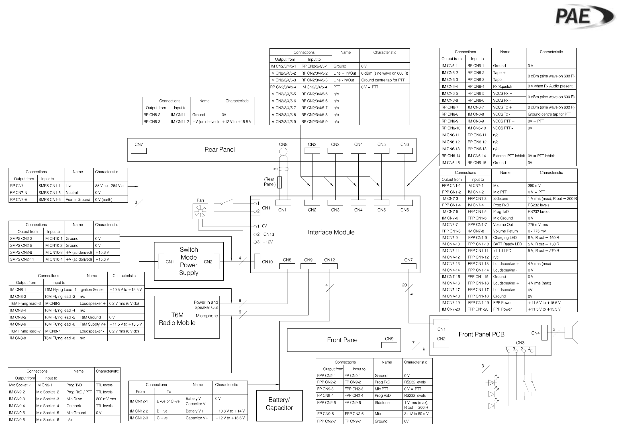
Base Station Interconnection Diagram
Figure 7
GA10548 Iss. 3
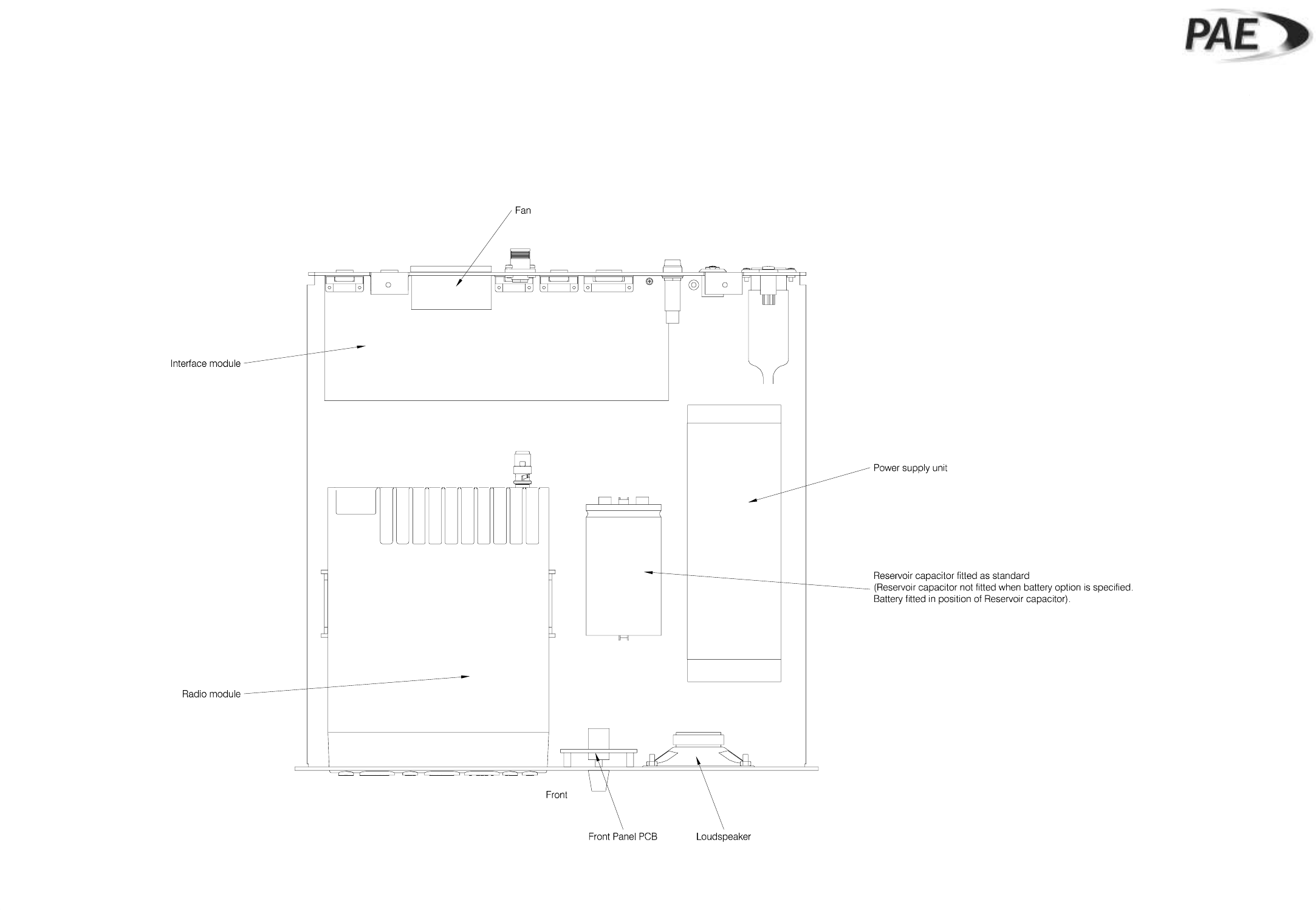
Base Station Layout Diagram
Figure 8
GA10719 Iss. 1
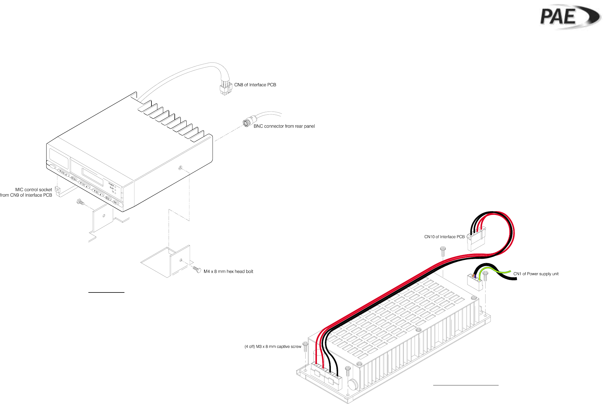
Radio Module and PSU Removal
Figure 9
GA10721 Iss. 1 (radio) and GA10731 Iss. 1 (PSU)
Radio Module
Power Supply Unit (PSU)
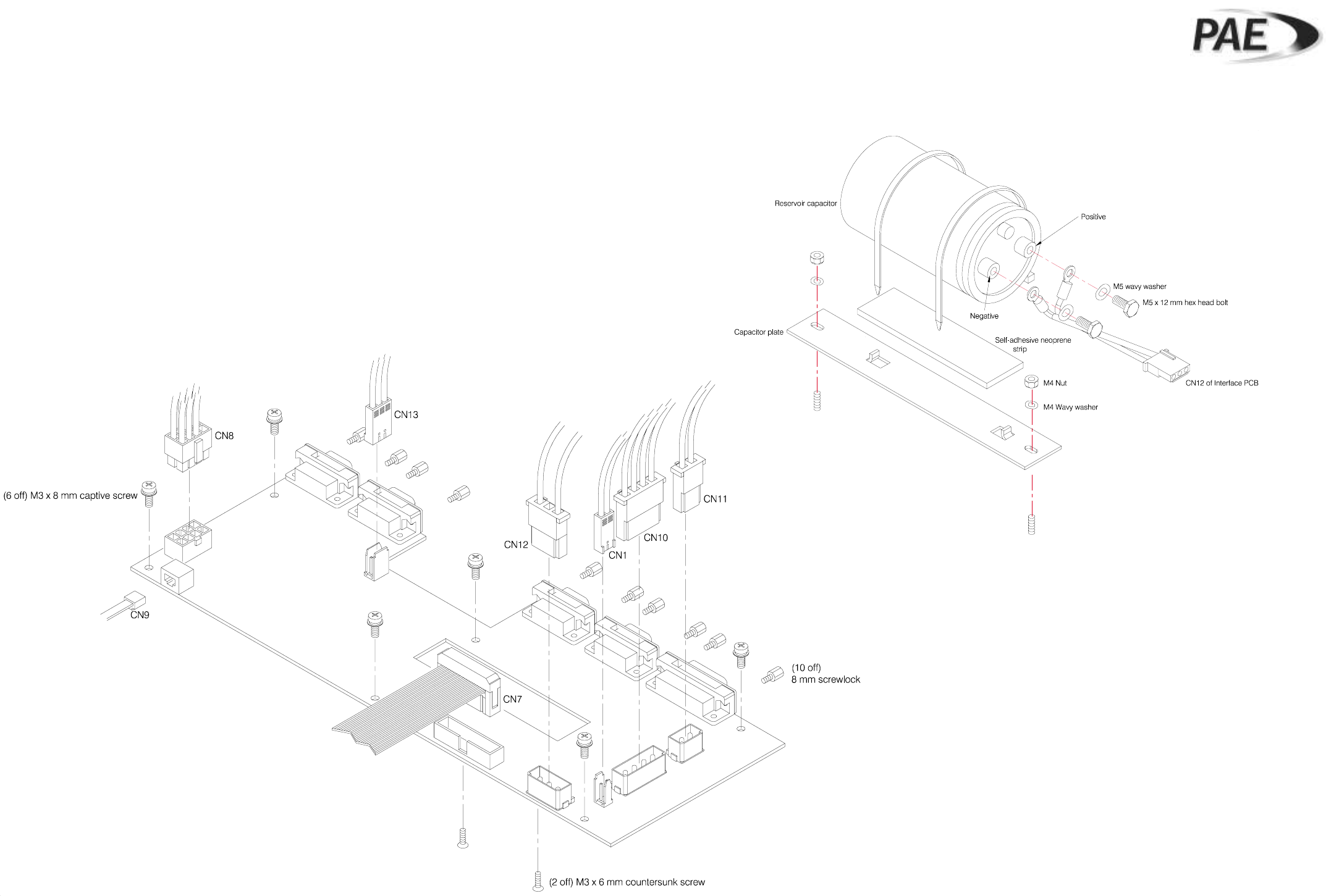
Interface PCB and Reservoir Capacitor
Removal
Figure 10
GA10732 Iss. 1 and GA10720 Iss. 1
Interface PCB
Reservoir Capacitor
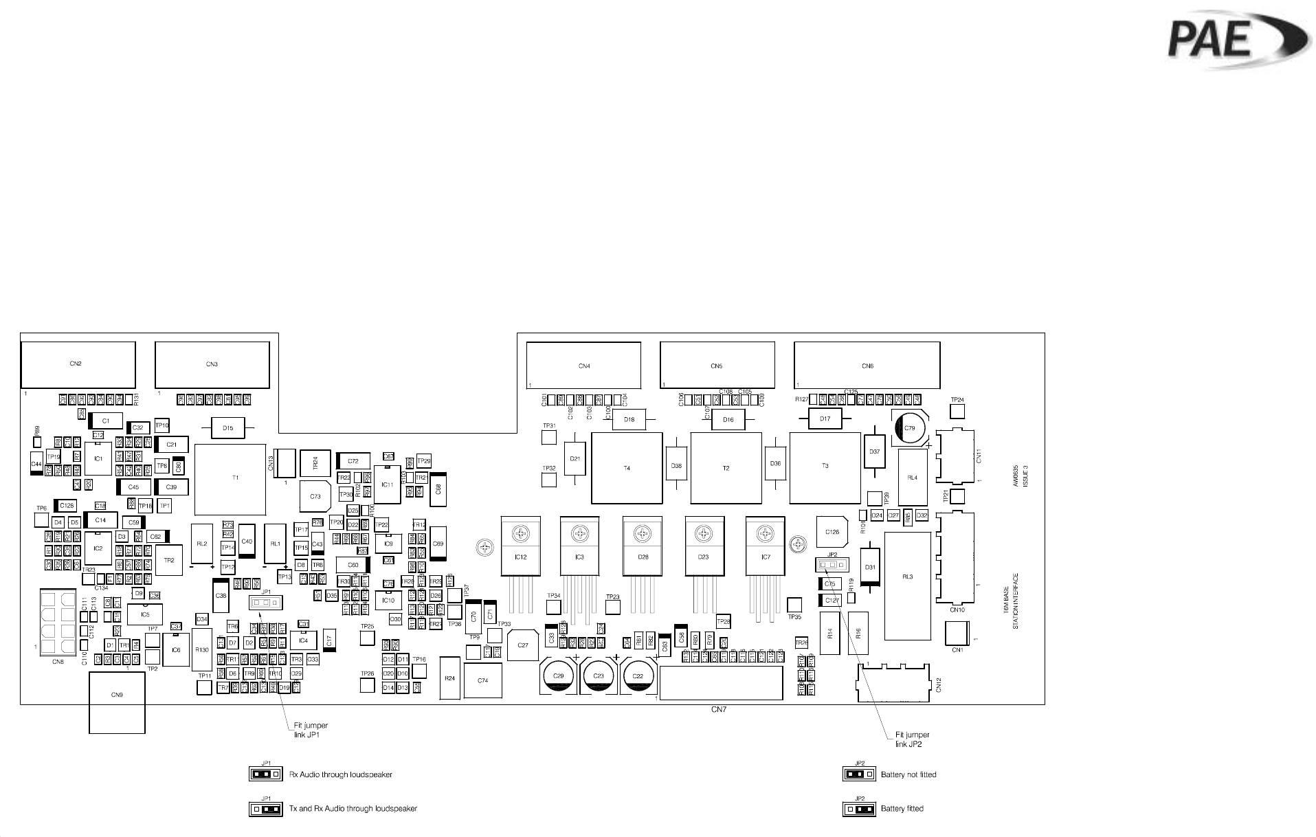
Interface PCB Layout Diagram
Figure 11
GA10751 Iss 1
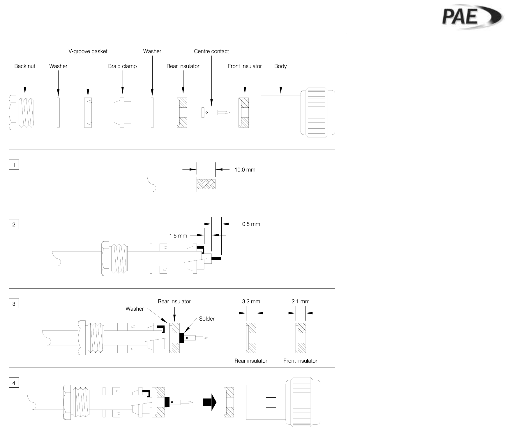
BT6MBS-12-1
Cable Termination at the N-Type Connector
Figure 12