Parker Hannifin MSLINK0003 2.4 GHz Radio Module User Manual x
MicroStrain, Inc. 2.4 GHz Radio Module x
manual
SerialLink Manual
Serial-Link Serial Packet Protocol (SPP) Draft version
1.20, for Internal MicroStrain use only
Working Draft: 8/7/2012
Overview
The Serial-Link Serial Packet Protocol (SPP) defines a standard for delivery of data and
commands over the Serial-Link UART communications pipeline. To communicate,
each device is capable of reading, responding to, and forwarding an SPP Packet. Any
device may originate a message and receive a reply from any other device. A single
packet may be delivered to multiple devices. If a device does not exist on the pipeline,
or is incapable of responding to a particular packet, it replies with an error, but will
propagate the packet to the next device, if it exists, so that the next device may respond to
the packet. The protocol to send a packet is shown below.
Hardware UART specifications
115,200 bps, no parity, 8 data bits, 1 stop bit
Packet Description
The basic structure of the SPP Packet looks like this:
Start Of Packet (SOP): 0xAA
Delivery Stop Flags: <1 byte>
App Data Type: <1 byte>
Node Address: <2 bytes>
Application data Length: <1 byte>
Application data: <0 to 100 bytes>
CheckSum: <2 bytes>
The size of the packet is always AppDataLength + 8 (except for a variant – see Packet
Variants) and the checksum is always the last 2 bytes (even for variants).
Start Of Packet (SOP) (1 byte: Pkt[0]):
The start of packet is a single byte of the value 0xAA (or binary 10101010)
Delivery Flags (1 byte: Pkt[1])
Delivery flag instructs the receiving device how to act upon reception of the packet.
This is currently fixed at a hex value 01H which instructs the receiving device to forward
the received packet over its UART.
App Data Type (previously: Address Mode) (1 byte: Pkt[2])
The App Data Type defines the type of the application data. It allows the target MCU to
determine what to do with the payload. If a target MCU does not recognize the App Data
Type, it simply ignores it (or generates an error reply). Even if a target does not
recognize the App Data Type, it should still pass the packet through to the next target (if
any).
All devices should utilize the Standard Command App Data Type (and the corresponding
Command Packet Reply) for most I/O. Standard command app data has an App Data
type value of 0. The Application Data in a standard command packet contains a 2 byte
(16 bit, MSB:LSB) command followed by command data (if any). The standard
command generally reflects available serial (non-packet) commands for a device. In
other words, the application data of a standard command data type is simply a standard
serial command wrapped in a packet header and checksum. If a Command Packet
generates a reply, the reply should be in a Command Packet Reply App Data Type. Other
standard App Data Types are:
App Data Type Name Description
00 Command packet 2 byte command + command data
01 Cmd Packet reply 2 byte echoed cmd + cmd result
02 Error reply packet 2 bytes of error code
Node Address (2 bytes: Pkt[3] Pkt[4])
In outbound packets the Node Address is the address of the wireless link node. The
exception is the “broadcast” address which is defined as 0xFFFF (65535). Packets
addressed to 0xFFFF are received and processed by all nodes.
The node address allows the Serial-Link pipeline to become a “star” network at the base
station to link board device. Each node on the star has an individual 16 bit address with
valid address values being in the range of 1 to 65535. Practically speaking, a single star
cannot have 65535 nodes at one time. The practical limit depends primarily on the duty
cycle of the nodes, the limitations of the supporting host software, and the link quality or
LQI (in the case of a wireless link).
Application Data Length (1 byte: Pkt[5])
The maximum application data is restricted to 100 bytes. It may contain any binary data.
Application Data (0 - 100 bytes: Pkt[6] -> Pkt[AppDataLen + 5])
In the SerialLink system, there are some commands carried in the application data that
are common to all devices and so no prior knowledge of the type of device is needed, but
there are many command and data application datas that are specific to a particular
device. These commands are referenced in the documentation for the particular device.

As a general convention, multi-byte values in the application data are recommended to be
represented as big-endian values (MSB:LSB). Several standard app data types
Checksum (2 bytes: Pkt[AppDataLen + 6], Pkt[AppDataLen + 7])
The checksum is a 16 bit big-endian integer (MSB:LSB) that is the byte-wise sum of all
the bytes in the packet starting AFTER the SOP and ending with the last byte of the
application data. The SOP is not part of the checksum. In packet variants (see Packet
Variants) additional packet bytes between the application data and the checksum bytes
are NOT included in the checksum. The length of the array that is checksummed is
AppDataLength + 5. The total size of the packet including the checksum bytes is
AppDataLength + 8.
POWERING THE DEVICE AND CONNECTING TO THE UART
The device is powered by providing a DC voltage between 3.3 volts and 10 volts on pin 4
of the input connector. The ground return is provided on Pin 14 of the input connector.
The voltage input is internally regulated to provide a steady 3.0 Voltage source to the
board.
Pin 19 is the Transmit Line of the UART, this should be connected to the receive line of
the interface microprocessor. Pin 18 is the RX Line of the UART, this should be
connected to the transmit line of the interface microprocessor. The interface voltage
levels should be 3.0 V +/ 0.3 V.
ALLOWABLE ANTENNAE
The device has been tested for FCC approval with the following antenna. This antenna
must be used with this module. The external antenna connects to the module via a u.FL
connector.
HG2402RD-RSF
Manufacturer: L-Com
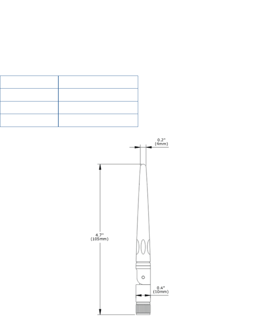
Electrical Specifications
Frequency 2400-2500 MHz
Gain 2.2 dBi
Impedance 50 Ohm
VSWR < 2.0
HOST PRODUCT LABELING:
The host product must be labeled with the following:
“Contains FCC ID: XJQMSLINK0003”
“Contains IC: 8505A-MSLINK0003”
HOST PRODUCT MANUAL STATEMENTS:
The host product user’s manual must contain the following statements when the Link
Data Transceiver is installed.
FCC –
“Changes or modifications not expressly approved by Microstrain, Inc. could void the
user’s authority to operate the device.”
“This device complies with Part 15 of the FCC Rules. Operation is subject to the
following two conditions: (1) this device may not cause harmful interference, and (2)
this device must accept any interference received, including interference that may cause
undesired operation.”
“To comply with RF exposure compliance requirements, the antenna used for this
transmitter must be installed to provide a separation distance of at least 20cm from all
persons and must not be co-located or operated in conjunction with any other antenna or
transmitter.”
INDUSTRY CANADA -
This device complies with Industry Canada licence-exempt RSS standard(s). Operation is
subject to the following two conditions: (1) this device may not cause interference, and
(2) this device must accept any interference, including interference that may cause
undesired operation of the device.
French:
Cet appareil est conforme avec Industrie Canada exempts de licence standard RSS (s).
L‘utilisation de ce dispositif est autorisée seulement aux conditions suivantes : (1) il ne
doit pas produire de brouillage et (2) l’ utilisateur du dispositif doit étre prêt à accepter
tout brouillage radioélectrique reçu, même si ce brouillage est susceptible de
compromettre le fonctionnement du dispositif.
Under Industry Canada regulations, this radio transmitter may only operate using an
antenna of a type and maximum (or lesser) gain approved for the transmitter by Industry
Canada. To reduce potential radio interference to other users, the antenna type and its
gain should be so chosen that the equivalent isotropically radiated power (e.i.r.p.) is not
more than that necessary for successful communication.
French:
Sous la réglementation d'Industrie Canada, ce transmetteur radio ne peut fonctionner en
utilisant une antenne d'un type et un maximum (ou moins) gain approuvées pour
l'émetteur par Industrie Canada. Pour réduire le risque d'interférence aux autres
utilisateurs, le type d'antenne et son gain doivent être choisis de manière que la puissance
isotrope rayonnée équivalente (PIRE) ne dépasse pas ce qui est nécessaire pour une
communication réussie.
This radio transmitter, IC ID: 8505A-MSLINK0003, has been approved by Industry
Canada to operate with the onboard antenna or a detachable WLAN antenna with a
maximum gain of 3.0dBi. Any other detachable antennas, with a different type or having
a gain greater than 3.0dB is strictly prohibited for use with this device. The required
antenna impedance is 50 ohms.
French:
Cet émetteur radio, IC ID: 8505A-MSLINK0003, a été approuvé par Industrie Canada
pour fonctionner avec l'antenne intégrée ou une antenne amovible PIFA avec un gain
maximum de 3.0dBi. Toute autre antenne détachable, avec un type différent ou ayant un
gain supérieur à 3.0dBi est strictement interdit pour une utilisation avec cet appareil.
L'impédance d'antenne requise est de 50 ohms.
Caution: Exposure to Radio Frequency Radiation.
To comply with RSS 102 RF exposure compliance requirements, for mobile
configurations, a separation distance of at least 20 cm must be maintained between the
antenna of this device and all persons. This device must not be co-located or operating in
conjunction with any other antenna or transmitter.
French:
Pour se conformer aux exigences de conformité 102 RSS RF exposition, pour des
configurations mobiles, une distance de séparation d'au moins 20 cm doit être maintenue
entre l'antenne de cet appareil et toutes les personnes. Cet appareil ne doit pas être co-
localisés ou fonctionnant en conjonction avec une autre antenne ou transmetteur.