Parker Hannifin MSLINK0008 Wireless Sensor Node User Manual My
Lord Corporation Wireless Sensor Node My
Exhibit D Users Manual per 2 1033 b3
LORD QUICK START GUIDE
SHM-Link-201
Ruggedized Wireless Structural Health Monitoring Node
NODEOVERVIEW
The SHM- Link- 201 structural health monitoring node is used for in- situ,
multidimensional measurement and analysis of component strain and fatigue.
The SHM-Link-201 has three input channels and is designed to integrate with
field-installed strain gauge rosettes.
The SHM-Link-201 embedded processing algorithms provide sophisticated data
outputs, including damage estimations using user- configurable strain number
curves, estimations along various user-configurable angles, and an ASTM e1049
rainflow- counting histogram output. Sampling modes include continuous and
activity-sense. The SHM-Link-201 is designed for extended use with a lithium
battery.
To acquire sensor data, the SHM-Link-201 is used with any LORD Sensing data
gateway, such as the WSDA®-Base -10
x
-LXRS®, or the network-ready WSDA®-
1500 - LXRS ®. The SensorConnect software interface is used for node
configuration, and SensorCloud™ is available for advanced data visualization,
aggregation, and analysis. Users can also build custom software interfaces with
the MicroStrain Communications Library (MSCL).
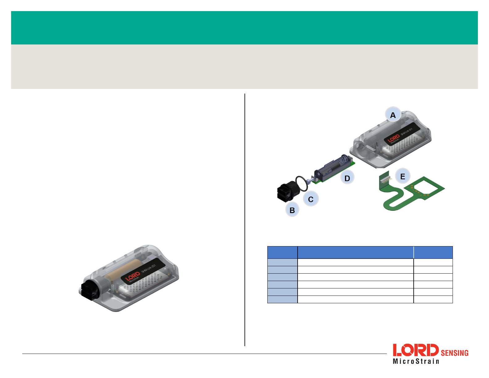
Figure 1 - Wireless Sensor Node
Figure 2 - Node Components
Item Description Quantity
ASHM-Link-201node assembly 1
BBattery compartment cap 1
CBattery compartment o-ring 1
DBattery tray 1
EStrain gauge bonding cable 1
FDielectric grease (not shown) 1
Table 1 - Component List
Wireless Simplicity, Hardwired Reliability™
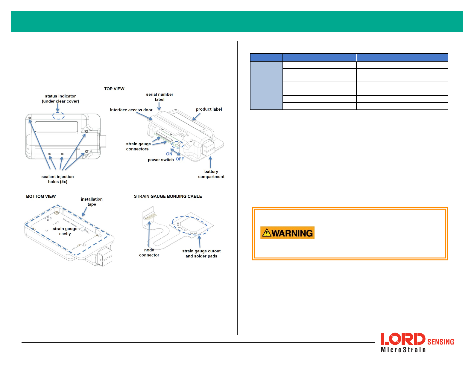
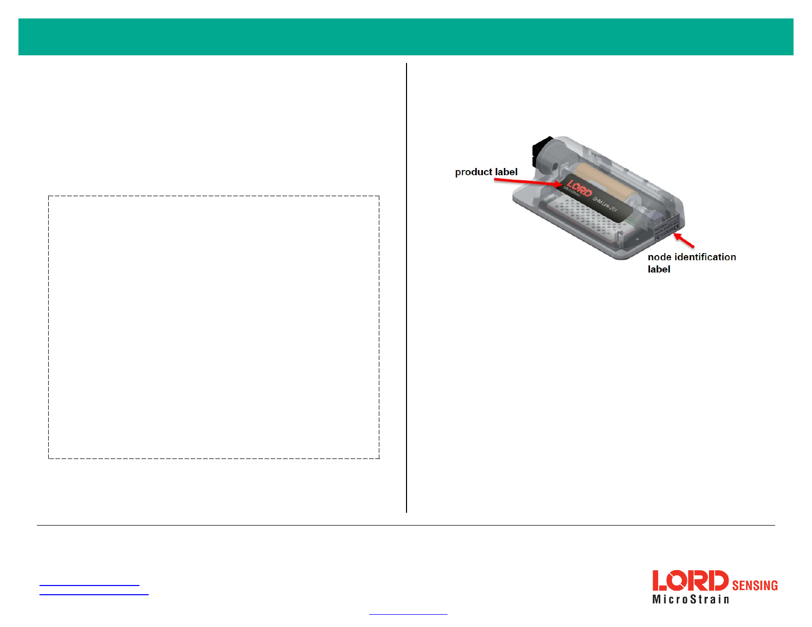
The SHM- Link- 201 interfaces includes a battery compartment and
accommodations for strain gauges and node installation. A device status
indicator is visible through a light-pipe below the product label.
Indicator Behavior Node Status
Device
status
indicator
OFF Node is OFF
Rapid multi-color flash on
start-up Node is booting up
Slow pulse ~ once/2 sec Node is idle and waiting for a
command
Quick blink ~ once/sec Node is sampling
Quick blink ~ once/10 sec Node is in sleep mode
Table 1 - Indicator Behaviors
NODEDEPLOYMENT
The SHM-Link-201 is designed for use with the provided bonding cable. The
cable connects the node and strain gauges in a way that allows the gauges to fit
underneath the node in the strain gauge cavity, protected from damage. The
strain gauge cavity can also be sealed after installation. The following procedure
outlines this process. These steps may not be necessary for all applications but
provide the best protection for the node circuitry and the gauges.
Install the Node Battery
The SHM-Link-201 operates on an internal
AA-type battery with a voltage between 1 V
dc and 5 V dc. Use only batteries that meet
this specification. Do not short circuit, crush,
puncture, or otherwise misuse the battery.
Disposal is subject to federal and local laws.
2
Wireless Sensor Node Quick Start Guide
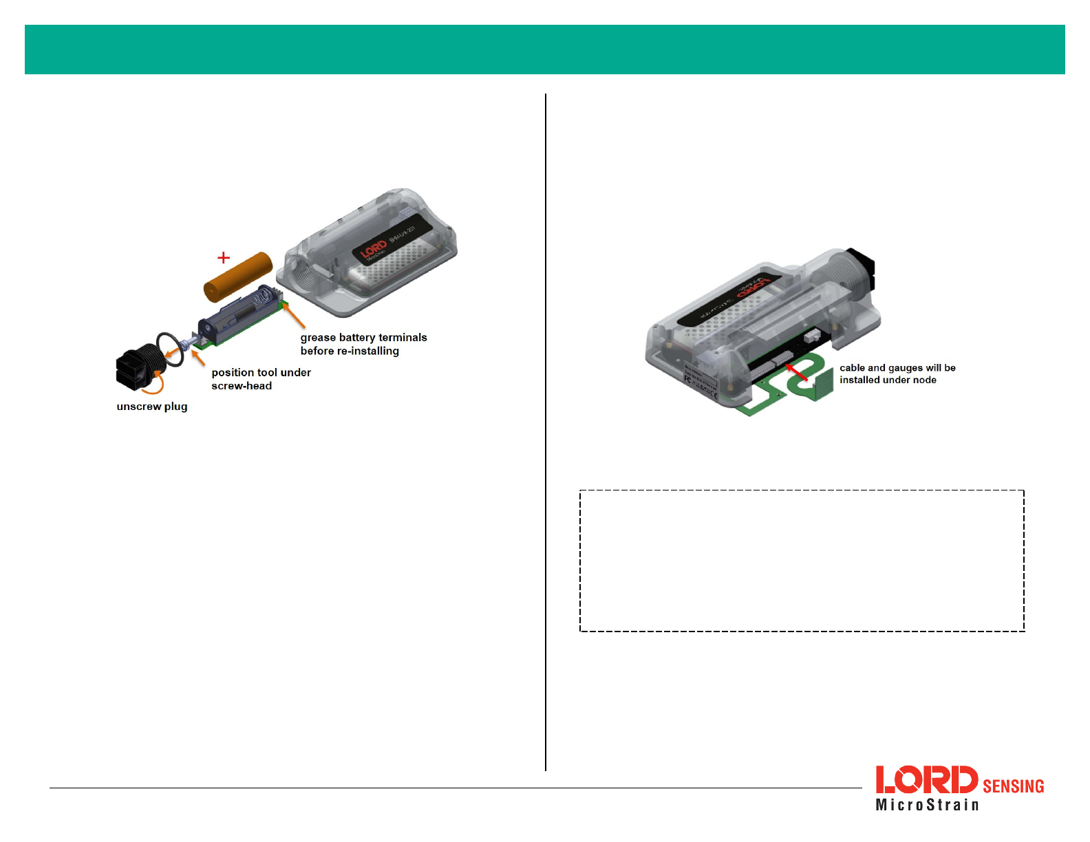
1. Remove the SHM-Link-201 battery compartment cap.
2. Position a pliers or a hook-ended tool behind the battery tray screw-head.
Pull firmly outward, or leverage the edge of the housing, to release the
tray from the terminals inside. It should unseat and slide out.
Figure 3 - Battery Compartment Assembly
3. Apply dielectric grease to the battery tray terminals.
4. Install the battery.
5. Firmly re-seat the battery tray in the battery compartment
6. Install the compartment cap, ensuring the o-ring remains intact and prop-
erly seated.
Test Fit Node and Gauge Assembly
7. Determine the location of the component to be monitored where the strain
gauges will be installed.
8. Place the bonding cable and node in the chosen location to verify gauge
placement and that there is space for the node to fit over the top of them.
The gauges are installed in the cable cutout, and the node strain gauge
cavity fits over the gauges and cable.
Figure 4 - Gauge and Node Location
Install Strain Gauges
NOTE
For accurate fatigue data, strain gauge installation must be completed in
compliance with strain gauge manufacturer recommendations and
industry standard processes such as
ASTM E1237-93, Standard Guide
for Installing Bonded Resistance Strain Gauges
. Failure to properly
attach and connect the gauges will result in erroneous data.
3
Wireless Sensor Node Quick Start Guide
9. Wire the strain gauges to the bonding cable so that the strain gauge
assembly will be positioned in the central cutout .
10. Bond the cable and strain gauges onto the surface of the component to be
monitored with strain gauge adhesive or equivalent. Install the gauges in
the desired orientation for measurement and in accordance with the strain
gauge manufacturers installation instructions.
Figure 5 - Strain Gauge Wiring
Connect Node to Strain Gauges and Test
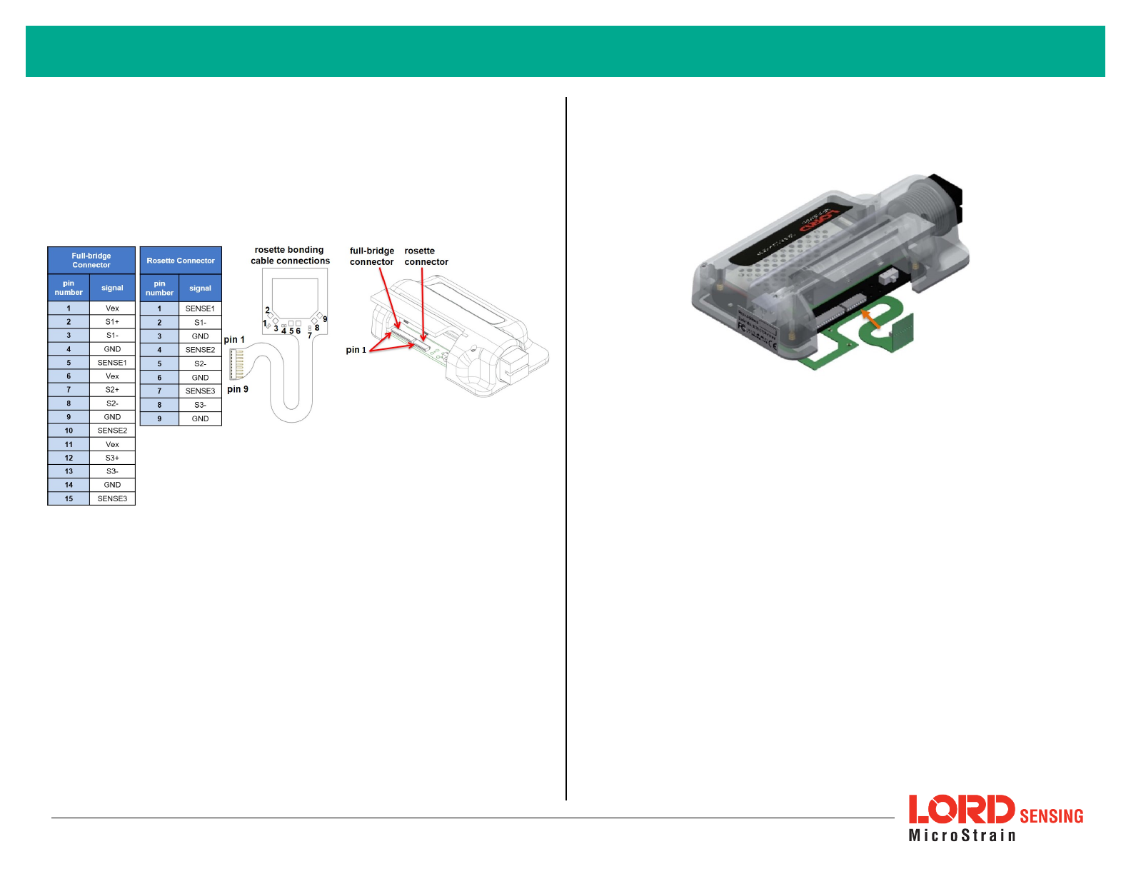
11. Connect the node to the strain gauge assembly. Attach the bonding cable
to one of the node connectors in the orientation shown. Two are provided
for node positioning convenience and have identical pins. The cable
should lay flat against the bottom of the node circuit board and wrap up
the edge of it to plug into the connecter.
12. Place the node over the strain gauge assembly and verify the strain
gauge cavity covers the strain gauge assembly without damaging it.
13. Test the strain gauage installation and basic node functioning by per-
forming an auto-calibration in SensorConnect (See Calibrate the Node on
page 7).
Figure 6 - Connecting to the Node
Install and Seal the Node
14. Remove the node battery or put it in sleep mode (to conserve battery life).
Verify the node power switch is in the ON position. Once the node is
sealed, the access door will no longer open.
15. Close the node interface access door and remove the installation tape
backing from the bottom of the node. Adhere the node in place over the
gauges.
16. Apply a high-strength adhesive sealant (such as Sikaflex®255 FC or equi-
valent) around the perimeter of the node where it meets the component
surface.
17. Remove the set screws from the sealant injection hole, and fill the strain
gauge cavity with a flexible, injectable sealant (such as Self-Levling
Green, or equivalent). Avoid over-filling the sealant and allowing it to leak
into other cavities (such as the battery compartment and under the access
door). This is more likely to happen if the node is mounted vertically.
4
Wireless Sensor Node Quick Start Guide
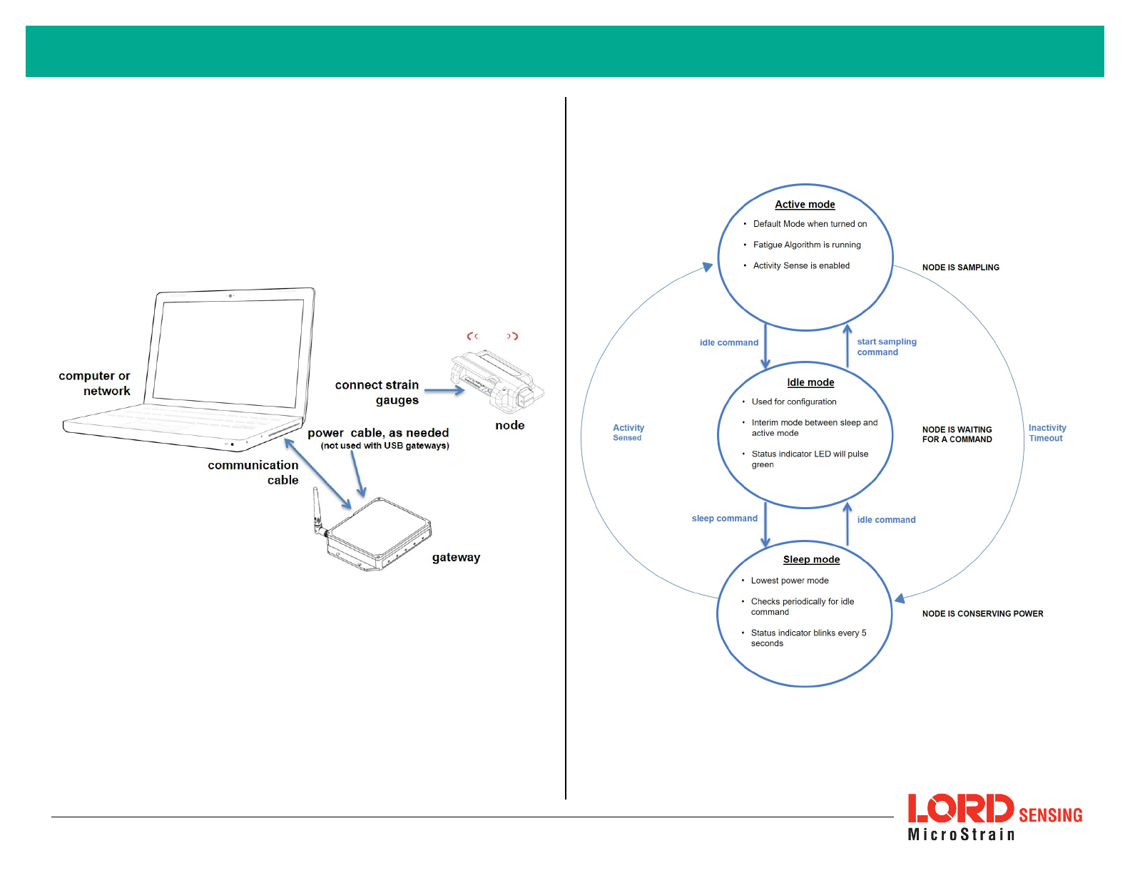
Make System Connections
To acquire sensor data, the SHM-Link-201 is used with a LORD Sensing data
gateway such as the WSDA®-200-USB or WSDA®-1500 - LXRS®. Connect the
gateway to the computer or network and to a power source as required. Refer to
the gateway user manual for more information.
Figure 7 - System Connections
Node Operational Modes
Figure 8 - Node Operational Modes
5
Wireless Sensor Node Quick Start Guide
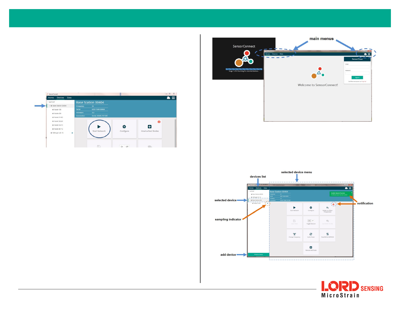
Synchronized Sampling
Use the Base Station menu to start sampling for multiple nodes in Synchronized
Sampling mode. For single nodes, or non- synchronized sampling, the node
menu can be used.
Figure 9 - Base Station Menu
Software Installation and Navigation
SensorConnect can be installed on any Windows operating system (Vista or
newer). The installer is downloaded from the LORD Sensing website and is also
provided with many products.
There are three main pages: Home, Devices, and Data, which are always
accessible at the top of page. A quick-link to the SensorCloud™ platform log-in
and a software settings menu is also available here. On start-up the software
scans for attached sensors and then opens the home page.
Figure 10 - SensorConnect Home Page
SensorConnect automatically detects any LORD Sensing device plugged into an
active port. Device connections are managed on the Devices page. The menu
options will vary between devices (such as gateways, nodes, and sensors) but
have similar interfaces.
Figure 11 - Devices Page
6
Wireless Sensor Node Quick Start Guide
Devices list - Found devices appear in the device list. This list also includes
previously found devices even when the software is restarted.
Selected device and device menu - Each type of device has its own menu. Once
selected, the device name is highlighted, and the corresponding menu displayed.
Menu options vary between devices but typically include device configuration,
start sampling, sensor mode selections, and data downloading. Click on the
device name (in the devices list) to get back to the main device menu.
Add Device - Manually add a device if it does not appear automatically. .
Notifications and indicators - information specific to a device, or in response to a
requested action, appears next to the applicable device name in the device list, or
in the device menu. These notifications provide information about device
performance, such as communication and sampling status. Green typically
indicates confirmed actions, while orange indicates information that may require
further action. Blue indicates they are currently sampling.
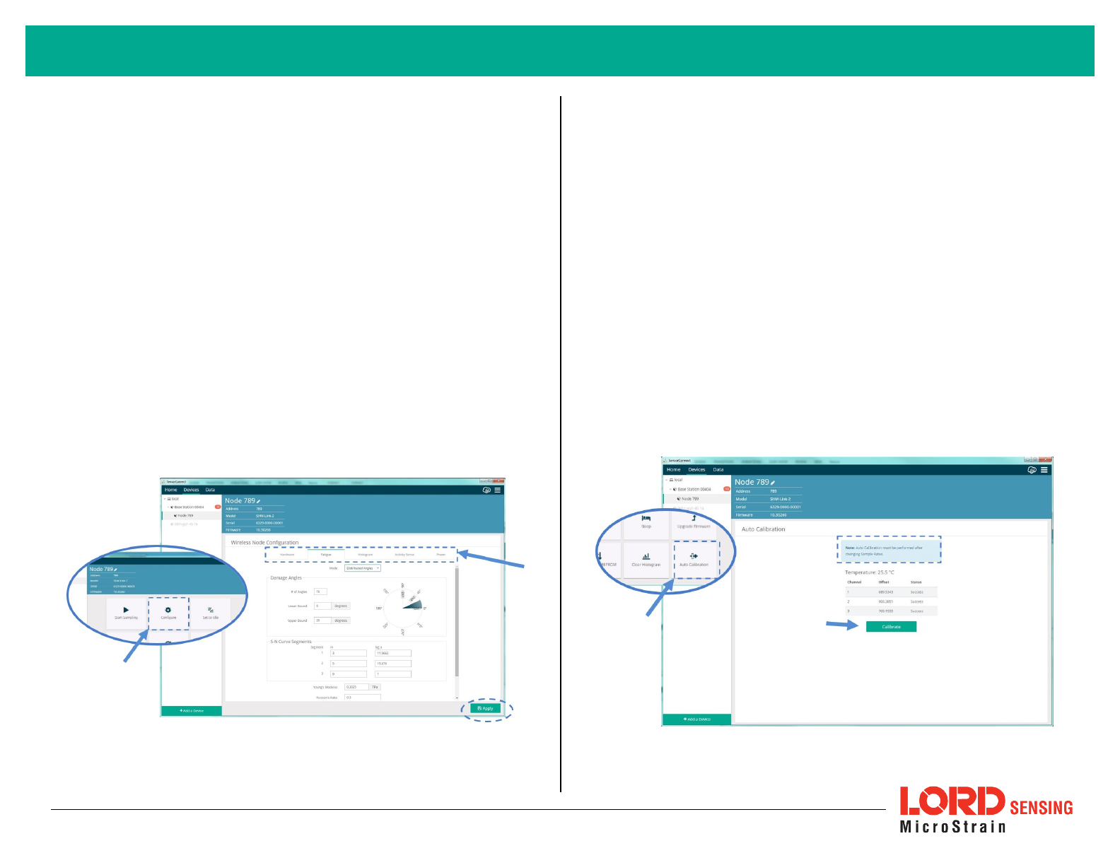
Configure the Node
Power settings, some sampling settings, data output options, and gauge settings
specific to the SHM-Link-201 are adjustable through the Configure menu. All
other settings are adjusted when sampling is started. Click Apply to save
changed settings.
Figure 12 - Configure Menu
Hardware - Set the strain gauge provided by the gauge manufacturer.
Fatigue - Select from data output options that produce fatigue measurements.
Histogram - Set the rainflow-counting bin thresholds and data transmit rate. Data
will still be collected at the rate set in the Start Sampling menu.
Activity Sense - Activity sense mode is power- saving mode. When enabled,
sampling will only occur when movement is detected by the internal
accelerometer. Sampling will occur at the rate set in the Start Sampling menu
until the (also configurable) inactivity period has passed.
Power - Set the node transmit power, radio-check interval (when the node goes
into sleep mode), and the inactivity timeout.
Calibrate the Node
Calibration of the SHM-Link-201 is done through an internal circuit. With the
strain gauges connected, simply open the Auto-Calibrate menu, and select the
Calibrate button. This will calibrate all three channels automatically. If the gauges
are connected correctly, and the calibration is completed, "Success" will be
indicated in the status column. Otherwise it will indicate the sensor is detached.
Figure 13 - Calibration Menu
7
Wireless Sensor Node Quick Start Guide
IMPORTANT:Auto- calibration must be
performed anytime sampling settings
are changed.
Start Sampling
Data sampling is initiated for each device through its device menu. For a wireless
sensor network, sampling can also be started for the entire network by initiating
sampling from the network gateway menu. The sampling menu options vary
depending on the type of device.
Figure 14 - Sampling Menu
Sampling menu - The sampling menu typically includes options for sampling
mode, sample rate, and sample duration. Apply the settings to begin collecting
data.
Sampling indicator - The sampling indicator shows when data is being collected
from the device. At slow sampling rates it will turn on and off as readings are
taken, while at fast sampling rates it will be on continuously.
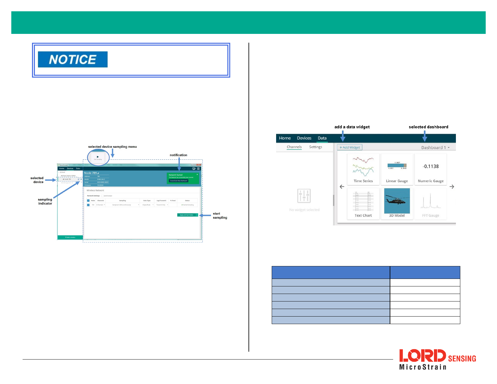
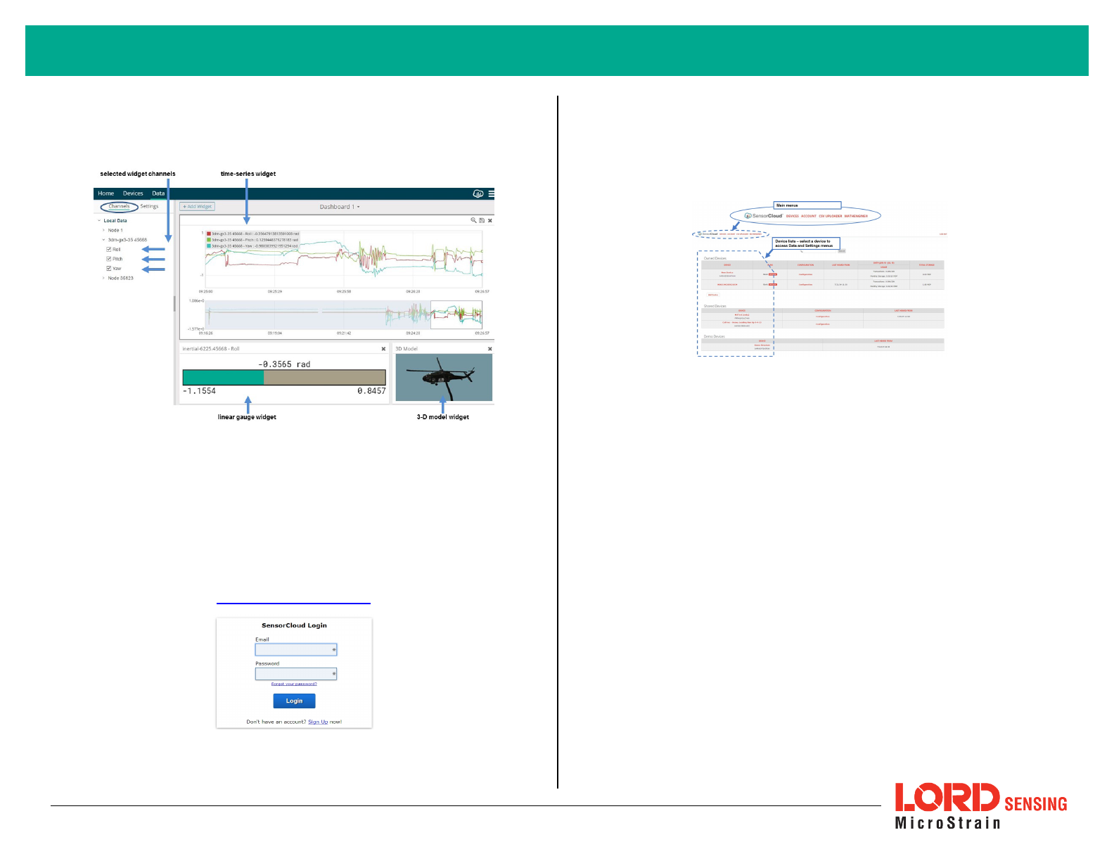
Create Data Views
Collected data is viewed on the Data page through the creation of dashboards
and widgets. Think of dashboards as individual pages and widgets as an
illustration on the page. Create multiple data widgets on each dashboard to
display sampled data as a time-series graph, text chart, or a simple gauge that
only displays the most current reading.
This format provides an easy way to organize many sensors and networks, and it
allows the information to be displayed in the most appropriate layout.
Figure 15 - Data Page
Use the mouse along with the shift and control keys inside the graph window to
adjust the data view.
Control Action
Mouse wheel Zoom in/out on
x
-axis
Shift + mouse wheel Zoom in/out on
y
-axis
Mouse double-click Zoom to extends
Shift + mouse left-click and drag left/right Zoom window left/right
Shift + mouse left-click and drag up/down Zoom window up/down
Ctrl +mouse left-click and drag Zoom box
Table 2 - Graph View Controls
8
Wireless Sensor Node Quick Start Guide
The widget configuration menu is different for each type of widget but typically
includes sensor or channel selections and widget settings such as titles and
legends.
Figure 16 - Widget Configuration Menu
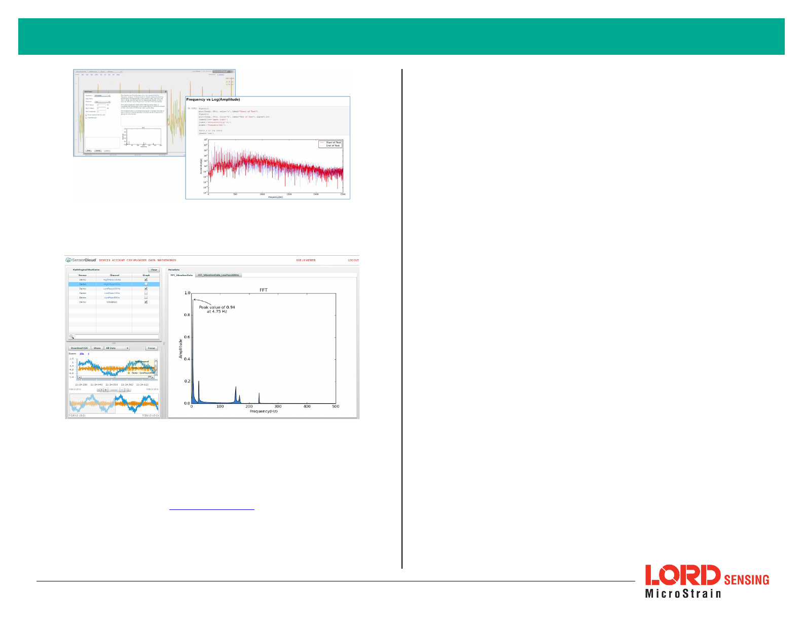
Connect to SensorCloud™
For global data aggregation, visualization, and analysis, data can be uploaded to
the SensorCloud web platform. Basic SensorCloud services are available to all
users free of charge.
Go to the SensorCloud website and select sign-in to enter the log-in credentials,
or register as a new user if needed.
http://sensorcloud.com/log-in/
Figure 17 - SensorCloud™ Log-in or Register
The SensorCloud interface has six main views . When logging in as a
registered user, the Device view is the default. Navigate to other views by
clicking the view name at the top of the page. The Data and Settings views
are only available once a device is selected from the device list.
Figure 18 - SensorCloud™ Menu Views
Device - The device list shows every Ethernet gateway and API device
associated with the SensorCloud account, including owned, shared, and demo
devices. This view provides links to each device’s SensorCloud subscription
plan, configuration options, and a summary of last communications and data
transactions.
Account - The account view is for logistic management of the SensorCloud
account, such as changing the log- in password, accessing user email, and
reviewing billing information.
CSVUploader - The data upload feature enables data from any source (such as
non-Ethernet LORD Sensing gateways or third-party sensor) to be uploaded to
the SensorCloud platform. The data must be in the LORD Sensing .CSV format.
9
Wireless Sensor Node Quick Start Guide
Wireless Sensor Node Quick Start Guide
Radio Specifications
The SHM-Link-201 employs a 2.4GHz IEEE 802.15.4-compliant radio transceiver
for wireless communication. The radio is a direct-sequence spread spectrum
radio and can be configured to operate on 16 separate frequencies ranging from
2.405 GHz to 2.480 GHz. Following the 802.15.4 standard, these frequencies are
aliased as channels 11 through 26. For all newly manufactured nodes, the
default setting is 2.425 GHz (channel 15).
FCC ID: XJQMSLINK0008
IC ID: 8505A-MSLINK0008
This device complies with Part 15 of the United States FCC Rules, and
Industry Canada’s license- exempt RSSs. Operation is subject to the
following two conditions: 1) This device may not cause interference, and
2) This device must accept any interference, including interference that
may cause undesired operation of the device. Changes or modifications,
including antenna changes not expressly approved by LORD
Corporation could void the user’s authority to operate the equipment.
Cet appareil est conforme à la Partie 15 des Règles de la FCC des
États-Unis et aux RSSS exempts de licence d'Industrie Canada. Le
fonctionnement est soumis aux deux conditions suivantes: 1) Cet
appareil ne doit pas causer d'interférences et 2) Cet appareil doit
accepter toute interférence, y compris les interférences pouvant
entraîner un fonctionnement indésirable de l'appareil. Les changements
ou modifications, y compris les changements d'antenne non
expressément approuvés par LORD Corporation, pourraient annuler
l'autorisation de l'utilisateur d'utiliser l'équipement.
Figure 21 - SHM-Link-201 Identification Labels
LORDCorporation
MicroStrain®Sensing Systems
459 Hurricane Lane , Suite 102
Williston, VT 05495 USA
ph: 802-862-6629
sensing_sales@LORD.com
sensing_support@LORD.com
Copyright © 2016 LORD Corporation
Document 8501-0091 Revision A. Subject to change without notice. www.microstrain.com