Parker Hannifin Er Users Manual
ER to the manual c42444ba-e2d9-4c26-b935-d2983d2a4c2a
2015-02-06
: Parker-Hannifin Parker-Hannifin-Er-Users-Manual-516710 parker-hannifin-er-users-manual-516710 parker-hannifin pdf
Open the PDF directly: View PDF ![]() .
.
Page Count: 44

Rotary Actuators and
Effective: July 1, 2000
Bulletin PM-ER01/USA
Maintenance
Instructions &
Parts List
ER Series
Rodless Actuator
Automation

Parker Hannifin Corporation
Automation Actuator Division
Wadsworth, Ohio
2
Automation
PM-ER01/USA
ER Series Rodless Actuator
Maintenance Instructions and Parts List
© Copyright 1997, Parker Hannifin Corporation, All Rights Reserved
The items described in this document are hereby offered for sale by Parker Hannifin Corporation, its subsidiaries or its authorized
distributors. This offer and its acceptance are governed by the provisions stated on the separate page of this document entitled "Offer of
Sale".
Offer of Sale
FAILURE OR IMPROPER SELECTION OR IMPROPER USE OF THE PRODUCTS AND/OR SYSTEMS DESCRIBED HEREIN OR
RELATED ITEMS CAN CAUSE DEATH, PERSONAL INJURY AND PROPERTY DAMAGE.
This document and other information from Parker Hannifin Corporation, its subsidiaries and authorized distributors provide product and/or
system options for further investigation by users having technical expertise. It is important that you analyze all aspects of your application
and review the information concerning the product or system in the current product catalog. Due to the variety of operating conditions and
applications for these products or systems, the user, through its own analysis and testing, is solely responsible for making the final selection
of the products and systems and assuring that all performance, safety and warning requirements of the application are met.
The products described herein, including without limitation, product features, specifications, designs, availability and pricing, are subject to
change by Parker Hannifin Corporation and its subsidiaries at any time without notice.
WARNING
Who's Who
ER Series Rodless Actuators
Voice (330)336-3511 - Fax (330)334-3335
Karen Dutt Ext. 122
David Bugajski Ext. 125
Mark Fisher Ext. 123
Ben Furnish Ext. 128
TBD Ext. 124 Electro-Mechanical Product Sales Manager
Bill Service Ext. 107 Marketing Manager
Roger Sherrard Ext. 103 General Manager
Order Entry & Expediting
Technical Information
Applications, Spare Parts
Programming

Parker Hannifin Corporation
Automation Actuator Division
Wadsworth, OH 44281
3
Automation
ER Series Rodless Actuator
PM-ER01/USA Maintenance Instructions and Parts List
Table of Contents
Description Page No.
Product Overview ............................................................................................... 4, 5
Ordering Information .......................................................................................... 6, 7
Parts Lists and Exploded Views
Actuators ................................................................................................. 9 - 15
Motor Mounts......................................................................................... 16 - 21
Maintenance
Cleaning ........................................................................................................ 22
Lubrication .................................................................................................... 22
Adjusting Timing Belt Tension ....................................................................... 23
Motor Coupler and Pulley Spacing ................................................................ 24
Torque Specifications .................................................................................... 25
Adhesives ..................................................................................................... 25
Bearing Carriage Adjustments ................................................................ 26 - 30
Belt Drive Tensioning ..................................................................................... 30
Motor Information
Step Motors ........................................................................................... 31 - 33
Brushless Servo Motors ......................................................................... 34 - 35
DC Brush Motors ................................................................................... 36 - 38
End of Travel and Home Sensor Information ................................................. 39 - 40
Brake Option ....................................................................................................... 41
Offer of Sale ........................................................................................................ 43

Parker Hannifin Corporation
Automation Actuator Division
Wadsworth, Ohio
4
Automation
PM-ER01/USA
ER Series Rodless Actuator
Maintenance Instructions and Parts List
The ER Series Rodless Actuator combines a robust, modular design with a variety of options that allow it to be tailored to
many applications. With two load bearing carriage styles available on all actuator sizes and two drive types (belt and screw
drive), the ER Series may be ordered specifically designed for the application. Combined with a Parker Hannifin stepper,
servo or DC brush system, the ER Series becomes a fully programmable linear actuator system.
ER Series Features
• Produced to hard metric ISO standards
• Three ISO mount sizes: 32mm, 50mm, 80mm
• Standard roller bearing carriage
• Square rail carriage option for greater load carrying capability
• Extruded, anodized aluminum body with t-slots for mounting switches and clamps
• Angular contact thrust bearings at rear of screw
• Polyurethane bumper at ends of travel
• Low-friction ball bearing nut and quality rolled ball screw option
• Low-friction burnished lead screw with bronze nut option
• Steel reinforced polyurethane drive belt (belt drives only)
• Integral sensing magnet
• High quality flexible couplings
• High performance stepper, servo and DC brush motors
• Designed for multi-axis connectivity (available from the Automation Actuator Division)
Motor Systems
• Microstepping systems
• DC Brushless servo systems with encoder or resolver feedback
• AutoDrive DC brush limit switch controller systems
• User provided AC or DC motor systems
ER Series Rodless Actuator
Product Information
Product Introduction and Features
Parker Hannifin Corporation
Automation Actuator Division
Wadsworth, OH 44281
5
Automation
ER Series Rodless Actuator
PM-ER01/USA Maintenance Instructions and Parts List
Features
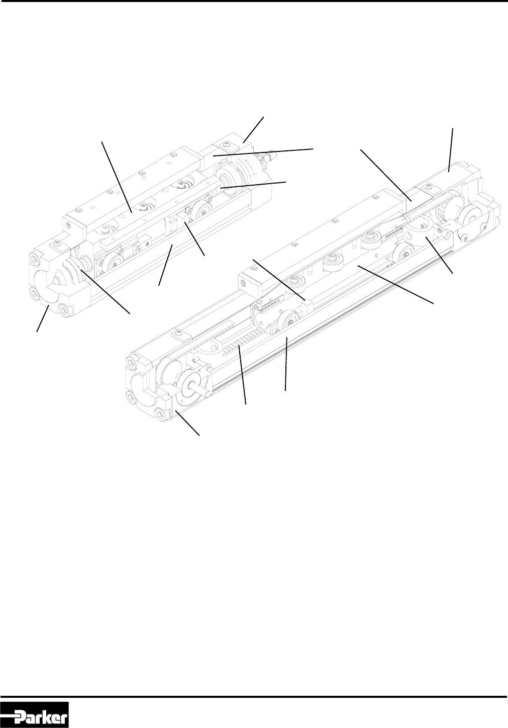
ER Series Overview
The figures below represent the main components of an ER Series Linear Actuator.
Screw Driven Unit
Front End Cap
Load Bearing Carriage
Actuator Body
Strip Seal
Load Bearing Carriage
Actuator Body
Rear End Cap
Rear End Cap
Belt Driven Unit
Front End Cap
Steel Reinforced
Polyurethane Drive Belt
Overstroke Bumper
Overstroke Bumper
Ball Screw or
Acme Lead Screw
Sensing Magnet
Parker Hannifin Corporation
Automation Actuator Division
Wadsworth, Ohio
6
Automation
PM-ER01/USA
ER Series Rodless Actuator
Maintenance Instructions and Parts List
Drive Ratio Availability
Step Motors and DC Brush Motors
Drive Ratio
Size 1:1 1:1.5 1.5:1 2:1
ERS/D32 2 2 — —
ERS/D50 2 & 3 — 2 & 3 2
ERS/D80 3 & 4 — 3 & 4 3
Model Code
Frame Size
2NEMA 23 (ER32, ER50)
3NEMA 34 (ER50, ER80)
4NEMA 42 (ER80)
9Special
Profile Size
32 32 mm
50 50 mm
80 80 mm
Series/Motor Type
ERS Stepper
ERB Servo
ERD DC Brush
Drive Type Available Sizes
A04 Acme Screw, 0.250 in lead ER32, 80
A05 Acme Screw, 0.200 in lead ER50
A08 Acme Screw, 0.125 in lead ER32
B01 Ball Screw, 1.000 in lead ER50, 80
B02 Ball Screw, 0.500 in lead ER50, 80
B04 Ball Screw, 0.250 in lead ER80
B05 Ball Screw, 0.200 in lead ER50
B08 Ball Screw, 0.125 in lead ER32
BLT Belt Drive All
ERS 50 – B05 R A 21 –
Motor Mounting Style – Screw Drive
LInline Motor Mounting
MParallel with Timing Belt, Motor Position 2
NParallel with Timing Belt, Motor Position 3
QParallel with Timing Belt, Motor Position 4
RReverse Parallel with Timing Belt, Motor Position 1
SReverse Parallel with Timing Belt, Motor Position 2
TReverse Parallel with Timing Belt, Motor Position 3
VReverse Parallel with Timing Belt, Motor Position 4
Motor Mounting Style – Belt Drive
RDirect Drive, Drive Right
LDirect Drive, Drive Left
M* Parallel with Timing Belt, Over Right
NParallel with Timing Belt, Under Right
S* Parallel with Timing Belt, Over Left
TParallel with Timing Belt, Under Left
VReverse Parallel with Timing Belt, Over Right
WReverse Parallel with Timing Belt, Under Right
YReverse Parallel with Timing Belt, Over Left
ZReverse Parallel with Timing Belt, Under Left
JReverse Parallel with Timing Belt, Rear Right
KReverse Parallel with Timing Belt, Rear Left
Drive Ratio
(See Tables Below for Availability)
A1:1 (Inline or Parallel)
B1.5:1 (Parallel)
D2:1 (Parallel)
Z1:1.5 (Parallel, ER32 only)
Option
0No Motor, Flange and Coupler/Pulley Only
1Std. Motor, Cable Grommet w/o Damper
2Std. Motor, Conduit Connector w/o Damper
3Std. Motor, Brad Harrison Connector, w/o Damper
4* Std. Motor, Cable Grommet w/ Damper
5* Std. Motor, Conduit Connector w/ Damper
6* Std. Motor, Brad Harrison Connector w/ Damper
9Used w/Frame Size 9, Special Motor to be Mounted
XUsed with Frame Sizes 2, 3, 4, Other Parker Motor
Step Motor and DC Brush Motor
* Not available with motor
codes 2n for ERB32 and
motor codes 6n and Jn
for ERB50
* Step motors only.
Parker Hannifin Corporation
Automation Actuator Division
Wadsworth, OH 44281
7
Automation
ER Series Rodless Actuator
PM-ER01/USA Maintenance Instructions and Parts List
Servo Motor
Motor Code Sizes
20 NEMA 23 Flange and Coupling/ Pulley Only ER32, 50
22 SM233BE-TTQN Motor with 10 ft. Cables ER32, 50
23 SM233BR-TMSN Motor with 10 ft. Cables ER32, 50
2X Other Parker NEMA 23 Motor to be Mounted ER32, 50
30 NEMA 34 Flange and Coupling/ Pulley Only ER50, 80
3X Parker NEMA 34 motor to be Mounted ER50, 80
60 Parker 92 mm Flange and Coupler/Pulley Only ER50, 80
6X Other Parker 92mm Motor to be Mounted ER50, 80
J1 J0922JR-KMSN with 25 ft. Cables ER50, 80
J2 J0923HR-KMSN with 25 ft. Cables ER50, 80
J3 J0923KR-KMSN with 25 ft. Cables ER80
90 Special Flange and Coupler/ Pulley Only Any
99 Special Motor to be Mounted Any
B S R E 150 L – A
Brake Option (ER50, 80)
OmitNo Brake
E1115 VAC with Flying Leads and Cable Gland
F124 VDC with Flying Leads and Cable Gland
G1115 VAC with Brad Harrison Conn.
and 4 m Cable
H124 VDC with Brad Harrison Conn.
and 4 m Cable
V2115 VAC w/ Flying Leads, Cable Gland on
Step Motor ( NEMA 34,42)
W224 VDC w/ Flying Leads, Cable Gland on
Step Motor (NEMA 34,42)
Y2115 VAC w/ Brad Harrison Conn. and
4 m Cable on Step Motor (NEMA 34, 42)
Z224 VDC w/ Brad Harrison Conn. and
4 m Cable on Step Motor (NEMA 34,42)
1Not available on inline screw drives or direct drive belt
drives. Not compatible with rear mounting options (B, H, N).
2Not compatible with damper or encoder options.
Carriage Style
SStandard
XSpecial (Consult Factory)
Carriage Bearing Style
RRoller Bearing Carriage
SSquare Rail Carriage
(Screw Drive Only)
A Assigned by Factory
Linear Potentiometer Option
Omit- No Linear Potentiometer
L- Linear Potentiometer
Stroke Sizes
50 50 mm (1.97 in.) ER32, 50
100 100 mm (3.94 in.) All
150 150 mm (5.91 in.) All
200 200 mm (7.87 in.) All
300 300 mm (11.81 in.) All
450 450 mm (17.72 in.) All
600 600 mm (23.62 in.) All
750 750 mm (29.53 in.) All
1000 1000 mm (39.37 in.) All
1250 1250 mm (49.21 in.) ER50, 80 Screw, All Belt
1500 1500 mm (59.05 in.) ER80 Screw, All Belt
Up to 2800 mm All Belt
Up to 3300 mm ER50, 80 Belt
Actuator Mounting Options
B* Foot Mount (MSI)
E* Rear Eye (MP4)
FBottom Tap (MS4) Standard
GFoot Side Lug, Screw Drive Only
H* Rear Flange (MF2)
Screw Drive Only
JFront Flange (MF1)
N* Front and Rear Flange (MF1 and MF2)
Screw Drive Only
XSpecial
* Parallel motor mounting only.
Drive Ratio Availability
Servo Motors
Drive Ratio
Size 1:1 1:1.5 1.5:1
ETB32 22 & 23 22 & 23 —
ETB50 22 & 23 — 22 & 23
J1/J2
ETB80 J1/J2/J3 — J1/J2/J3
Model Code

Parker Hannifin Corporation
Automation Actuator Division
Wadsworth, Ohio
8
Automation
PM-ER01/USA
ER Series Rodless Actuator
Maintenance Instructions and Parts List
Parker Hannifin Corporation
Automation Actuator Division
Wadsworth, OH 44281
9
Automation
ER Series Rodless Actuator
PM-ER01/USA Maintenance Instructions and Parts List
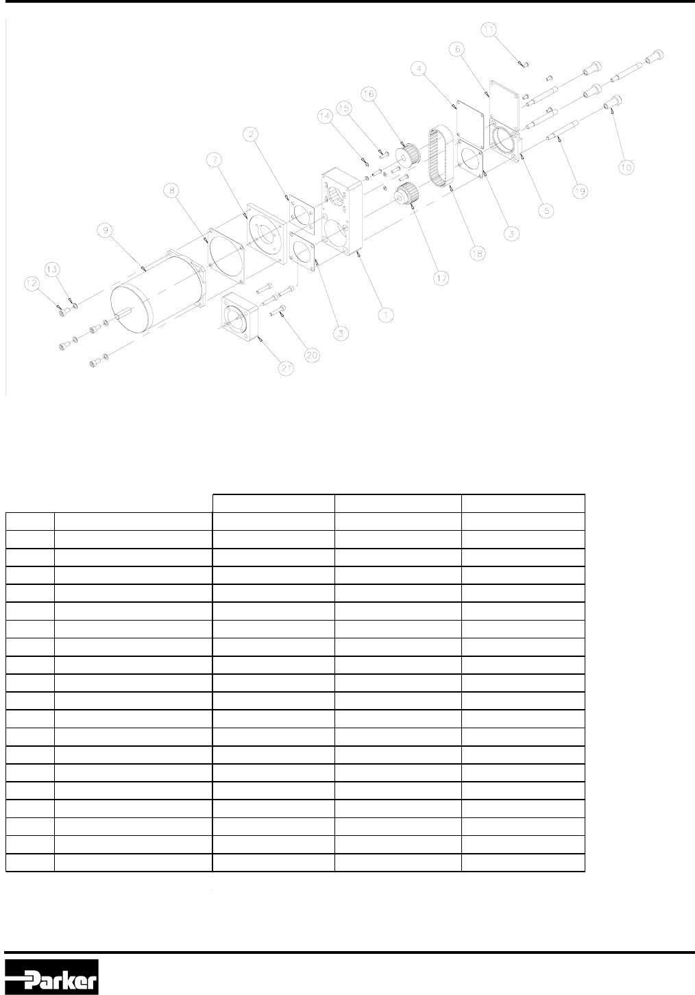
Parts List Introduction
The ER Series Rodless Actuator is available in three basic form factors, each of which carries a separate exploded
view drawing and parts list. After determining your ER form factor, refer to the parts list section corresponding to that
form factor.
1 Parts listed on page 13.
Screw Drive Belt Drive
DRIVE TYPE
BEARING TYPE
ER Series Form Factors
Square Rail
Bearing Roller Bearing
Roller Bearing
Pages 10-11
Motor Mounting Styles
The ER Series Rodless Actuator includes pre-mounted DC stepper, brushless servo or brush motors. Motors may
be mounted inline, or directly coupled to the screw shaft (screw drive) or pulley shaft (belt drive). Alternatively, motor
may be mounted in a variety of parallel (or reverse-parallel) configurations. Parallel mounting link the motorshaft and
actuator drive shaft through a timing belt and pulley system. Refer to the model code pages (pp. 6-7) and Catalog
1894, Electromechanical Actuator Products, for a detailed description of the many mounting possibilities. Each
motor mounting assembly may be applied to all ER Series types: screw and belt drive, roller bearing and square rail.
Pages 14-15
Pages 12-13
MOTOR MOUNTING
TYPE Parallel MountInline Mount
Pages 16-17 Pages 18-19
Parker Hannifin Corporation
Automation Actuator Division
Wadsworth, Ohio
10
Automation
PM-ER01/USA
ER Series Rodless Actuator
Maintenance Instructions and Parts List
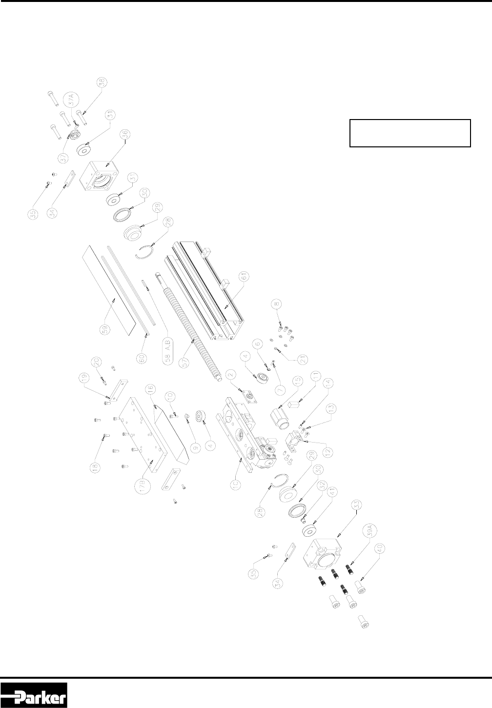
ER Series Roller Bearing Carriage and Screw Drive
Exploded View- Roller Bearing/Screw Drive
←←
←←
← Drawing Orientation

Parker Hannifin Corporation
Automation Actuator Division
Wadsworth, OH 44281
11
Automation
ER Series Rodless Actuator
PM-ER01/USA Maintenance Instructions and Parts List
PART DESCRIPTION QTY 32 50 80
1C CARRIAGE BODY, ROLLER 1 ER32R03RS ER50R03RS ER80R03RS
2 ROLLER PLATE 4 ER32R10 ER50R10 ER80R10
4 ROLLER WHEEL A SSEMBLY 7 ER32RCA ER50RCA ER80RCA
6 BEA RING RETAINER 4 ET32R04 ET32R04 ET80R04
7 BEA RING RETAINER SCREWS 4 CFT-CM3X0.5-008 CFT-CM3X0.5-008 CF-CM6X1.0-016
8 ROLLER PLATE BOLTS 16 CS-CM3X0.5-006 CS-CM4X0.7-008 CS-CM5X0.8-016-Z
9 ECCENTRICS 3 ER32R12 ER32R12 ER80R04
10 TOP ROLLER SCREWS 3 CB-CM4X0.7-012 CS-CM4X0.7-016 CS-CM6X1.0-020
11 SWITCH MAGNETS 2 ER32M10 ER80M10 ER80M10
12 NUT RETAINER 1 ER32R07 ER50R07 ER80R07
13 NUT RETAINER SCREWS 4 CF-CM4X0.7-012 CF-CM4X0.7-012 CF-CM6X1.0-020
14 NUT RETAINER SET SCREWS 2 SB-CM4X0.7-006 SB-CM6X1.0-008 SB-CM81.25-010
15 ACME\BALL SCREW NUT 1 TNXXXXX TNXXXXX TNXXXXX
16 U.H.M.W. COVER SLIDE 1 ER32R14BSC ER50R14BSC ER80R14BSC
17B TOP LOAD PLATE (SCREW) 1 ER32R05-S ER50R05-S ER80R05-S
18 TOP LOAD PLATE SCREWS 8 CS-CM3X0.5-010-Z CS-CM4X0.7-012-Z CS-CM5X0.8-016-Z
19 STRIP GUIDES 2 ER32R06 ER50R06 ER80R06
20 STRIP GUIDES SCREWS 4 CS-CM3X0.5-008-Z CS-CM4X0.7-008-Z CS-CM4X0.7-010-Z
21 SERRATED WASHER 16 B2124 B2125 B2115
28 END CAP SNAP RINGS 2 BNVH-112 BNVH-162 BNVH-275
29 CARRIAGE STOPS 2 ER32M02 ER50M02 ER80M02
30 SCREW DRIV E END CAP BUMPERS 2 ET32M01 ET50M01 ET80M01
31 THRUST BEARINGS 2 RA 373 RA336 RA342
32 SCREW SHAFT SLEEVE 1 ER32R08 N/A N/A
33 SCREW DRIV E OPP.SIDE END CAP 1 ER32E01 ER50E01 ER80E01
34 STRIP GUIDE CLAMP 2 ER32M05 ER50M05 ER80M05
35 STRIP GUIDE CLAMP SCREWS 4 CB-CM4X0.7-008-Z CB-CM4X0.7-008-Z CB-CM4X0.7-008-Z
36 SCREW DRIV E MOTOR SIDE END CAP 1 ER32E02 ER50E02 ER80E02
37 BEARING LOCKNUT 1 ET32R07 B8777 B8776
37A BEA RING LOCKNUT SCREW 1 CS-CM3X0.5-008 SUPPLIED SUPPLIED
38 SCREW DRIVE END SHCS IN LINE 4 CS-CM5X0.8-030 CS-CM6X1.0-035 CS-CM8X1.25-050
39A TIE ROD BOLTS 4 M6-M5-A M8-M6-A M10-M8-A
40 TIE ROD NUTS 4 32-27015 50-27015 80-27015
41 RADIAL BEARING 1 RA339 RA374 RA375
57 ACME/BALL SCREW 1 ERTSXXXXXNXXXXXX ERTSXXXXXNXXXXXX ERTSXXXXXNXXXXXX
58A ACME/BALL SCREW KEY IN LINE 1 B8534M2-06 B8534M2-08 B8534M5-14
58B ACME/BALL SCREW KEY PARALLEL 1 B8534M2-20 B8534M3-20 B8534M5-32
59 STRIP SEAL 1 ER32M06BSC ER50M06BSC ER80M06BSC
60 STRIP SEAL MAGNETS 2 ER32M11BSC ER32M11BSC ER32M11BSC
61 BODY 1 ER32CXXXX ER50CXXXX ER80CXXXX
Parts List-Roller Bearing/Screw Drive
Parker Hannifin Corporation
Automation Actuator Division
Wadsworth, Ohio
12
Automation
PM-ER01/USA
ER Series Rodless Actuator
Maintenance Instructions and Parts List
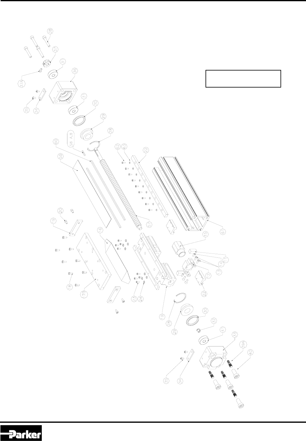
ER Series Square Rail Carriage and Screw Drive
←←
←←
← Drawing Orientation
Exploded View- Square Rail/Screw Drive

Parker Hannifin Corporation
Automation Actuator Division
Wadsworth, OH 44281
13
Automation
ER Series Rodless Actuator
PM-ER01/USA Maintenance Instructions and Parts List
PART DESCRIPTION QTY 32 50 80
1B CARRIAGE BODY , SQUA RE RA IL 1 ER32R03SS ER50R03SS ER80R03SS
11 SWITCH MAGNETS 2 ER32M10 ER80M10 ER80M10
12 NUT RETA INER 1 ER32R07 ER50R07 ER80R07
13 NUT RETAINER SCREWS 4 CF-CM4X0.7-012 CF-CM4X0.7-012 CF-CM6X1.0-020
14 NUT RETAINER SET SCREWS 2 SB-CM4X0.7-006 SB-CM6X1.0-008 SB-CM81.25-010
15 ACME\BALL SCREWS NUT 1 TNXXXXX TNXXXXX TNXXXXX
16 U.H.M.W. COV ER SLIDE 1 ER32R14BSC ER50R14BSC ER80R14BSC
17B TOP LOAD PLATE (SCREW) 1 ER32R05-S ER50R05-S ER80R05-S
18 TOP LOAD PLATE SCREWS 8 CS-CM3X0.5-010-Z CS-CM4X0.7-012-Z CS-CM5X0.8-016-Z
19 STRIP GUIDES 2 ER32R06 ER50R06 ER80R06
20 STRIP GUIDES SCREWS 4 CS-CM3X0.5-008-Z CS-CM4X0.7-008-Z CS-CM4X0.7-010-Z
22 SQUARE RAIL BEARING SETS 1 RA377-XXXX RA378-XXXX RA379-XXXX
23 SQUARE RAIL BEARING SCREWS 8 CS-CM3X0.5-020 CS-CM3X0.5-008 CS-CM5X0.8-035
24 SERRATED WASHER 8 B2124 B2125 B2125
28 END CAP SNAP RINGS 2 BNVH-112 BNVH-162 BNVH-275
29 CARRIAGE STOPS 2 ER32M02 ER50M02 ER80M02
30 SCREW DRIVE END CAP BUMPERS 2 ET32M01 ET50M01 ET80M01
31 THRUST BEA RINGS 2 RA 373 RA336 RA342
32 SCREW SHAFT SLEEV E 1 ER32R08 N/A N/A
33 SCREW DRIV E OPP.SIDE END CA P 1 ER32E01 ER50E01 ER80E01
34 STRIP GUIDE CLA MP 2 ER32M05 ER50M05 ER80M05
35 STRIP GUIDE CLAMP SCREWS 4 CB-CM4X0.7-008-Z CB-CM4X0.7-008-Z CB-CM4X0.7-008-Z
36 SCREW DRIV E MOTOR SIDE END CA P 1 ER32E02 ER50E02 ER80E02
37 BEARING LOCKNUT 1 ET32R07 B8777 B8776
37A BEA RING LOCKNUT SCREW 1 CS-CM3X0.5-008 SUPPLIED SUPPLIED
38 SCREW DRIVE END SHCS IN LINE 4 CS-CM5X0.8-030 CS-CM6X1.0-035 CS-CM8X1.25-050
39A TIE ROD BOLTS 4 M6-M5-A M8-M6-A M10-M8-A
40 TIE ROD NUTS 4 32-27015 50-27015 80-27015
41 RADIAL BEARING 1 RA339 RA374 RA375
57 ACME/BALL SCREW 1 ERTSXXXXXNXXXXXX ERTSXXXXXNXXXXXX ERTSXXXXXNXXXXXX
58A ACME/BALL SCREW KEY IN LINE 1 B8534M2-06 B8534M2-08 B8534M5-14
58B ACME/BALL SCREW KEY PARALLEL 1 B8534M2-20 B8534M3-20 B8534M5-32
59 STRIP SEAL 1 ER32M06BSC ER50M06BSC ER80M06BSC
60 STRIP SEAL MAGNETS 2 ER32M11BSC ER32M11BSC ER32M11BSC
61 BODY 1 ER32CXXXX ER50CXXXX ER80CXXXX
62 SQUARE RAIL SCREWS - CS-CM3X0.5-006 CS-CM3X0.5-006 CS-CM4X0.7-016
63 SQUA RE RA IL SCREW WASHERS - B2124 B2125 B2125
Parts List- Square Rail/Screw Drive
Parker Hannifin Corporation
Automation Actuator Division
Wadsworth, Ohio
14
Automation
PM-ER01/USA
ER Series Rodless Actuator
Maintenance Instructions and Parts List
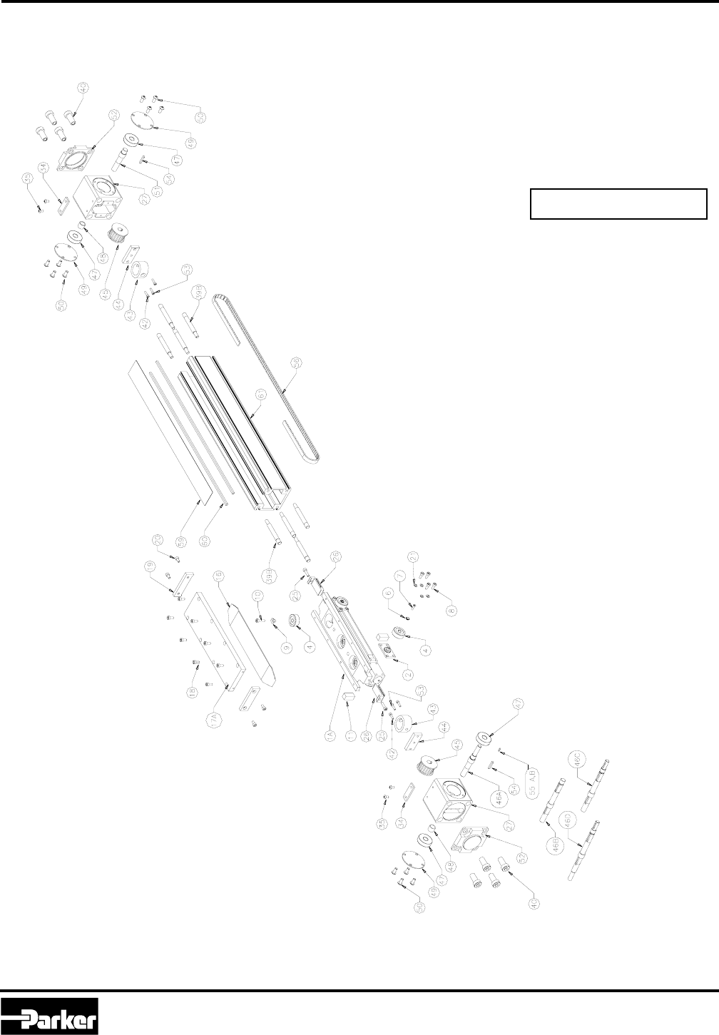
ER Series Roller Bearing Carriage and Belt Drive
Exploded View- Roller Bearing/Belt Drive
←←
←←
← Drawing Orientation

Parker Hannifin Corporation
Automation Actuator Division
Wadsworth, OH 44281
15
Automation
ER Series Rodless Actuator
PM-ER01/USA Maintenance Instructions and Parts List
Parts List- Roller Bearing/Belt Drive
PART DESCRIPTION QTY 32 50 80
1A CA RRIA GE BODY, BELTED 1 ER32R03RB ER50R03RB ER80R03RB
2 ROLLER PLATE 4 ER32R10 ER50R10 ER80R10
4 ROLLER WHEEL A SSEMBLY 7 ER32RCA ER50RCA ER80RCA
6 BEARING RETAINER 4 ET32R04 ET32R04 ET80R04
7 BEARING RETA INER SCREWS 4 CFT-CM3X0.5-008 CFT-CM3X0.5-008 CF-CM6X1.0-016
8 ROLLER PLATE BOLTS 16 CS-CM3X0.5-006 CS-CM4X0.7-008 CS-CM5X0.8-016-Z
9 ECCENTRICS 3 ER32R12 ER32R12 ER80R04
10 TOP ROLLER SCREWS 3 CB-CM4X0.7-012 CS-CM4X0.7-016 CS-CM6X1.0-020
11 SWITCH MAGNETS 2 ER32M10 ER80M10 ER80M10
16 U.H.M.W. COVER SLIDE 1 ER32R14BSC ER50R14BSC ER80R14BSC
17A TOP LOAD PLATE (BELTED) 1 ER32R05-SB ER50R05-SB ER80R05-SB
18 TOP LOAD PLATE SCREWS 8 CS-CM3X0.5-010-Z CS-CM4X0.7-012-Z CS-CM5X0.8-016-Z
19 STRIP GUIDES 2 ER32R06 ER50R06 ER80R06
20 STRIP GUIDES SCREWS 4 CS-CM3X0.5-008-Z CS-CM4X0.7-008-Z CS-CM4X0.7-010-Z
21 SERRATED WASHER 16 B2124 B2125 B2115
25 BELT CLAMP ADJ. SCREWS 2 CS-CM4X0.7-016 CS-CM4X0.7-016 CS-CM5X0.8-018
26 BELT CLA MP 2 ER32R09 ER50R09 ER80R09
27 BELT DRIV E END CAPS 2 ER32E03 ER50E03 ER80E03
34 STRIP GUIDE CLA MP 2 ER32M05 ER50M05 ER80M05
35 STRIP GUIDE CLAMP SCREWS 4 CB-CM4X0.7-008-Z CB-CM4X0.7-008-Z CB-CM4X0.7-008-Z
39B TIE ROD BOLTS 4 M6-M5-C M8-M6-C M10-M8-C
40 TIE ROD NUTS 8 32-27015 50-27015 80-27015
42 BUMPER PLATE MOUNTING SCREWS 4 CS-CM3X0.5-012 CS-CM3X0.5-010 CS-CM5X0.8-010
43 BELT DRIVE BUMPER 2 B8504-32ER B8504-50ER B8504-80ER
44 BELT DRIV E BUMPER PLA TE 2 ER32M12 ER50M12 ER80M12
45 BELT DRIVE PULLEY 2 ER32P01 ER50P01 ER80P01
46A BELT DRIV E IN LINE SHAFT 1 ER32S02 ER50S02 ER80S02
46B BELT DRIV E PA RA LLEL SHA FT 1 ER32S03 ER50S03 ER80S03
46C BELT DRIV E PA RA LLEL SHA FT W/ BK 1 N/A ER50S04 ER80S04
46D BELT DRIV E PARA LLEL W/ LINK & BK 1 N/A ER50S09 ER80S09
47 BELT DRIVE BEARINGS 4 RA382 RA374 RA375
48 BELT DRIVE SHAFT SPACER 2 ER32S05 ER50S05 ER80S05
49 BELT DRIV E END CAP COV ERS 3 ER32M07 ER50M07 ER80M07
50 BELT DRIVE E.C. COVERS SCREW 12 CB-CM3X0.5-008-Z ESF4005-12 ESF4006-08
51 BELT DRIVE IDLER SHAFT 1 ER32S01 ER50S01 ER80S01
52 BELT DRIV E END MOUNTING CA PS 2 ET32E07 ET50E07 ET80E07
53 BELT DRIVE BUMPER SCREWS 2 CS-CM5X0.8-012 CS-CM5X0.8-020 CS-CM6X1.0-010
54 BELT DRIVE IDLER SHAFT KEYS 2 B8534M2-14 B8534M3-20 B8534M5-25
55A BELT DRIVE IN LINE SHAFT KEY 1 B8534M2-06 B8534M2-08 B8534M5-14
55B BELT DRIVE PARALLEL KEY. 1 B8534M2-20 B8534M2-20 B8534M5-32
56 BELT DRIVE BELT 1 ER32B01BSC ER50B01BSC ER80B01BSC
59 STRIP SEAL 1 ER32M06BSC ER50M06BSC ER80M06BSC
60 STRIP SEAL MAGNETS 2 ER32M11BSC ER32M11BSC ER32M11BSC
61 BODY 1 ER32CXXXX ER50CXXXX ER80CXXXX
Parker Hannifin Corporation
Automation Actuator Division
Wadsworth, Ohio
16
Automation
PM-ER01/USA
ER Series Rodless Actuator
Maintenance Instructions and Parts List
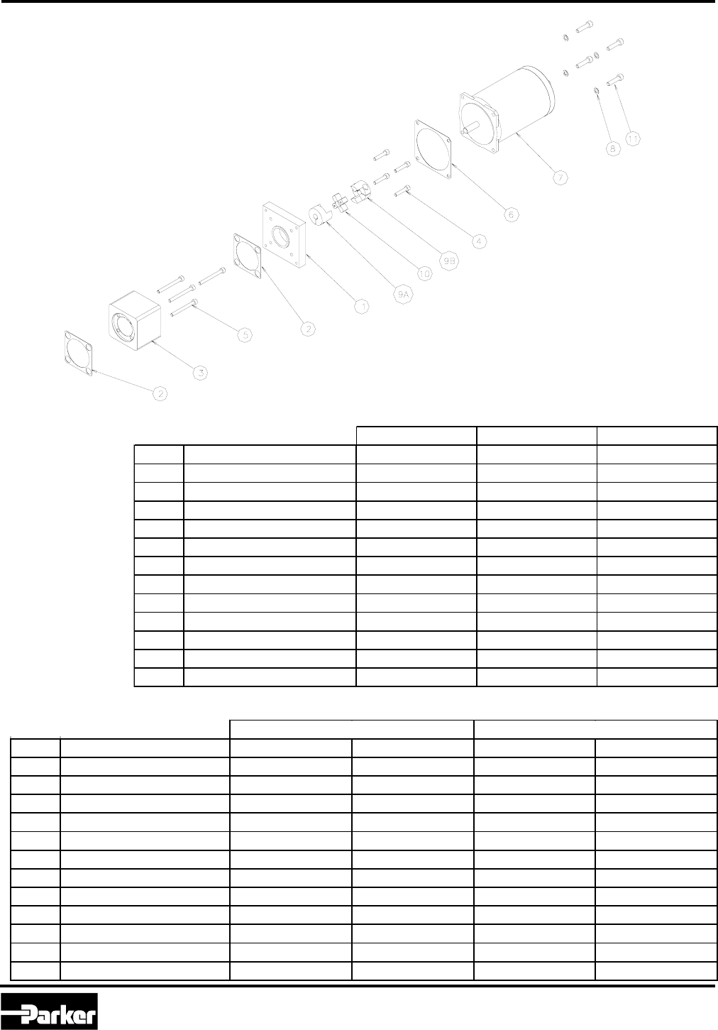
Exploded View- Inline Motor Mounting
ER Series Inline Motor Mounting
Step Motors Servo Motors DC Brush Motors
Part No. Description S57-102 SM233B AD23A
1 MOTOR ADAPTOR FLANGE ET32E05 ET32E09 ET32E05
2 GASKET ET32M05 ET32M05 ET32M05
3 COUPLER HOUSING ET32E04 ET32E04 ET32E04
4 FLANGE MOUNTING BOLTS CFT-CM3X0.5-012 CS-CM3X0.5-025 CFT-CM3X0.5-012
5 COUPLER HOUSING SCREWS CS-CM3X0.5-035 CS-CM3X0.5-035 CS-CM3X0.5-035
6 GASKET ET50M06 ET50M06 ET50M06
7 MOTOR S57-102MO M233B (2 VERSIONS) AD23A-048-10
8 WASHER WS-SLR-CM05-Z WS-SLR-CM05-Z WS-SLR-CM05-Z
9A SCREW COUPLER GCM100602 RGSM090602 GCM100602
9B MOTOR COUPLER GC102500 RGS093813 GC102500
10 COUPLER INSERT GC12-SU RGS0998 GC12-SU
11 MOTOR MOUNTING SCREWS CS-CM5X0.8-012-Z CS-CM5X0.8-018-Z CS-CM5X0.8-012-Z
Step Motors Servo Motors
Part No. Description S57-102 S83-135 SM233B J092
1 MOTOR ADAPTOR FLANGE N/A ET50E05 N/A ET50E11
2 GASKET ET50M05 ET50M05 ET50M05 ET50M05
3 COUPLER HOUSING ET50E04 ET50E04 ET50E15 ET50E04
4 FLANGE MOUNTING BOLTS N/A CS-CM5X0.8-016 N/A CF-CM5X0.8-016
5 COUPLER HOUSING SCREWS CS-CM5X0.8-050 CS-CM5X0.8-050 CS-CM5X0.8-050 CS-CM5X0.8-050
6 GASKET ET50M06 ET50M13 ET50M06 ET50M11
7 MOTOR S57-102MO S83-135MO M233B (2 VERSIONS) J092 (3 VERSIONS)
8 WASHER WS-SLR-CM05-Z WS-SLR-CM05-Z WS-SLR-CM05-Z WS-SLR-CM06-Z
9A SCREW COUPLER GCM18082 GCM18082 RGSM140802 RGSM140802
9B MOTOR COUPLER GC182500 GC183800 RGS143813 RGS141405
10 COUPLER INSERT GC19-SU GC19-SU RGS1498 RGS1498
11 MOTOR MOUNTING SCREWS CS-CM5X0.8-016-Z CS-CM5X0.8-016-Z CS-CM5X0.8-018-Z CS-CM6X1.0-025-Z
ER50
ER32
Parker Hannifin Corporation
Automation Actuator Division
Wadsworth, OH 44281
17
Automation
ER Series Rodless Actuator
PM-ER01/USA Maintenance Instructions and Parts List
DC Brush Motors
Part No. De s cription AD23A AD34A
1 MOTOR ADAPTOR FLANGE N/A ET50E05
2 GASKET ET50M05 ET50M05
3 COUPLER HOUSING ET50E04 ET50E04
4 FLANGE MOUNTING BOLTS N/A CS-CM5X0.8-016
5 COUPLER HOUSING SCREWS CS-CM5X0.8-050 CS-CM5X0.8-050
6 GASKET ET50M06 ET50M13
7 MOTOR AD23A-048-10 AD34A-048-10
8 WASHER WS-SLR-CM05-Z WS-SLR-CM05-Z
9A SCREW COUPLER GCM18082 GCM18082
9B MOTOR COUPLER GC182500 GC183800
10 COUPLER INSERT GC19-SU GC19-SU
11 MOTOR MOUNTING SCREWS CS-CM5X0.8-016-Z CS-CM5X0.8-016-Z
Step Motors Servo Motors
Part No. Description S83-135 S106-178 J092 APEX620
1 MOTOR A DAPTOR FLA NGE N/A ET80E05 N/A ET80E11
2 GASKET ET80M05 ET80M05 ET80M05 ET80M05
3 COUPLER HOUSING ET80E04 ET80E04 ET80E14 ET80E04
4 FLANGE MOUNTING BOLTS N/A CF-CM5x0.8-020 N/A CF-CM5X0.8-030
5 COUPLER HOUSING SCREWS CS- CM6x 1.0-080 CS-CM6x 1.0-080 CS-CM6x 1.0-080 CS-CM6x 1.0-080
6 GASKET ET80M13 ET80M12 ET50M11 ET100M12
7 MOTOR S83-135 S106-178 J092 (3 VERSIONS) APEX620
8 WASHER WS-SLR-CM05-Z WS-SLR-CM06-Z WS-SLR-CM06-Z ESF1108
9A SCREW COUPLER GCM401405 GCM401405 RGSM191405 RGSM191405
9B MOTOR COUPLER GC403800 GC406313 RGS RGSM192408
10 COUPLER INSERT GC42-SU GC42-SU RGS1998 RGS1998
11 MOTOR MOUNTING SCREWS CS-CM5X0.8-016-Z ESF4106-20 CS-CM6X1.0-025-Z CS-CM8X1.25-035-Z
DC Br us h M otor s
Part No. Description AD34A AD42A
1 MOTOR ADAPTOR FLANGE N/A ET80E05
2 GASKET ET80M05 ET80M05
3 COUPLER HOUSING ET80E04 ET8 0E04
4 FLANGE MOUNTING BOLTS N/A CF-CM5x0.8-020
5 COUPLER HOUSING SCREWS CS-CM6x1.0-080 CS-CM6x 1.0- 080
6 GASKET ET80M13 ET80M12
7 MOTOR AD34A-048-10 AD42A-090-10
8 WA SHER WS- SLR- CM05- Z WS-SLR- CM06- Z
9A SCREW COUPLER GCM401405 GCM401405
9B MOTOR COUPLER GC403800 GC406313
10 COUPLER INSERT GC42-SU GC42-SU
11 MOTOR MOUNTING SCREWS CS-CM5X0.8-016-Z ESF4106-20
Exploded View- Inline Motor Mounting
ER50
ER80
ER80
Parker Hannifin Corporation
Automation Actuator Division
Wadsworth, Ohio
18
Automation
PM-ER01/USA
ER Series Rodless Actuator
Maintenance Instructions and Parts List
Exploded View- Parallel Motor Mounting
Step Motors Servo Motors DC Brush Motors
Part No. Description S57-102 SM233B AD23A
1 PARALLEL MOUNT HOUSING ET32E06 ET32E06 ET32E06
2 GASKET ET32M09 ET32M09 ET32M09
3 GASKET ET32M05 ET32M05 ET32M05
4 GASKET ET32M08 ET32M08 ET32M08
5 END CAP ET32E07 ET32E07 ET32E07
6 PARALLEL MOUNT COVER ET32E10 ET32E10 ET32E10
7 MOTOR ADAPTOR FLANGE ET32E08 ET32E08 ET32E08
8 GASKET ET50M06 ET50M06 ET50M06
9 MOTOR S57-102 SM233B (2 VERSIONS) AD23A-048-10
10 TIE ROD NUT 32-27015 32-27015 32-27015
11 COVER SCREWS CB-CM3X0.5-008-Z CB-CM3X0.5-008-Z CB-CM3X0.5-008-Z
12 MOTOR MOUNTING SCREWS CS-CM5X0.8-012-Z CS-CM5X0.8-014-Z CS-CM5X0.8-012-Z
13 WASHER WS-SLR-CM05-Z WS-SLR-CM05-Z WS-SLR-CM05-Z
14 WASHER B2128-M4 B2128-M4 B2128-M4
15 ADAPTOR SCREWS CB-CM4X0.7-010 CB-CM4X0.7-010 CB-CM4X0.7-010
16-18 SEE PULLEY-BELT TABLES
19 PARALLEL MOUNT STUD B8805-M6-50 B8805-M6-50 B8805-M6-50
20 ADPATOR SCREWS* CS-CM3X0.5-020 CS-CM3X0.5-020 CS-CM3X0.5-020
21 ER BELT DRIV E A DA PTOR* ER32M09 ER32M09 ER32M09
* ER BELT DRIV E ONLY
ER32

Parker Hannifin Corporation
Automation Actuator Division
Wadsworth, OH 44281
19
Automation
ER Series Rodless Actuator
PM-ER01/USA Maintenance Instructions and Parts List
ER50
Step Motors Servo Motors
Part No. Description S57-102 S83-135 SM233B J092
1 PARALLEL MOUNT HOUSING ET50E06 ET50E06 ET50E06 ET50E06
2 GASKET ET50M09 ET50M09 ET50M09 ET50M09
3 GASKET ET50M05 ET50M05 ET50M05 ET50M05
4 GASKET ET50M08 ET50M08 ET50M08 ET50M08
5 END CAP ET50E07 ET50E07 ET50E07 ET50E07
6 PARALLEL MOUNT COVER ET50E10 ET50E10 ET50E10 ET50E10
7 MOTOR ADAPTOR FLANGE ET50E08 ET50E09 ET50E08 ET50E17
8 GASKET ET50M06 ET50M06 ET50M06 ET50M06
9 MOTOR S57-102 S83-135 SM233B (2 VERSIONS) J092 (3 VERSIONS)
10 TIE ROD NUT 50-27015 50-27015 50-27015 50-27015
11 COVER SCREWS CB-CM4X0.7-012-Z CB-CM4X0.7-012-Z CB-CM4X0.7-012-Z CB-CM4X0.7-012-Z
12 MOTOR MOUNTING SCREWS CS-CM5X0.8-012-Z CS-CM5X0.8-012-Z CS-CM5X0.8-014-Z CS-CM6X1.0-025-Z
13 WASHER WS-SLR-CM05-Z WS-SLR-CM05-Z WS-SLR-CM05-Z WS-SLR-CM06-Z
14 WASHER B2128-M5 B2128-M5 B2128-M5 B2128-M5
15 ADAPTOR SCREWS CB-CM5X0.8-010 CB-CM5X0.8-010 CB-CM5X0.8-010 CB-CM5X0.8-010
16-18 SEE PULLEY-BELT TABLES
19 PARALLEL MOUNT STUD B8805-M8-60 B8805-M8-60 B8805-M8-60 B8805-M8-60
20 ADAPTOR SCREWS* CS-CM5X0.8-025 CS-CM5X0.8-025 CS-CM5X0.8-025 CS-CM5X0.8-025
21 ER BELT DRIV E ADA PTOR* ER50M09 ER50M09 ER50M09 ER50M09
* ER BELT DRIVE ONLY
DC Brush Motors
Part No. Description AD23A AD34A
1 PARALLEL MOUNT HOUSING ET50E06 ET50E06
2 GASKET ET50M09 ET50M09
3 GASKET ET50M05 ET50M05
4 GASKET ET50M08 ET50M08
5 END CAP ET50E07 ET50E07
6 PARALLEL MOUNT COVER ET50E10 ET50E10
7 MOTOR ADAPTOR FLANGE ET50E08 ET50E09
8 GASKET ET50M06 ET50M06
9 MOTOR AD23A-048-10 AD34A-048-10
10 TIE ROD NUT 50-27015 50-27015
11 COVER SCREWS CB-CM4X0.7-012-Z CB-CM4X0.7-012-Z
12 MOTOR MOUNTING SCREWS CS-CM5X0.8-012-Z CS-CM5X0.8-012-Z
13 WASHER WS-SLR-CM05-Z WS-SLR-CM05-Z
14 WASHER B2128-M5 B2128-M5
15 ADA PTOR SCREWS CB-CM5X0.8-010 CB-CM5X0.8-010
16- 18 SEE PULLEY - BELT TA BLES
19 PARALLEL MOUNT STUD B8805-M8-60 B8805-M8-60
20 ADAPTOR SCREWS* CS-CM5X0.8-025 CS-CM5X0.8-025
21 ER BELT DRIVE ADAPTOR* ER50M09 ER50M09
* ER BELT DRIVE ONLY
Exploded View- Parallel Motor Mounting

Parker Hannifin Corporation
Automation Actuator Division
Wadsworth, Ohio
20
Automation
PM-ER01/USA
ER Series Rodless Actuator
Maintenance Instructions and Parts List
Exploded View- Parallel Motor Mounting
Step Motors Servo Motor
Part No. Description S83-135 S106-178 J092
1 PARALLEL MOUNT HOUSING ET80E06 ET80E06 ET80E06
2 GASKET ET80M09 ET80M09 ET80M09
3 GASKET ET80M05 ET80M05 ET80M05
4 GASKET ET80M08 ET80M08 ET80M08
5 END CAP ET80E07 ET80E07 ET80E07
6 PARALLEL MOUNT COVER ET80E10 ET80E10 ET80E10
7 MOTOR ADAPTOR FLANGE ET80E08 ET80E09 ET80E16
8 GASKET ET80M13 ET80M12 ET50M11
9 MOTOR S83-135 S106-178 J092 (3 VERSIONS)
10 TIE ROD NUT 80-27015 80-27015 80-27015
11 COVER SCREWS ESF4005-12 ESF4005-12 ESF4005-12
12 MOTOR MOUNTING SCREWS CS-CM5X0.8-012-Z CS-CM6X1.0-016-Z ESF4106-20
13 WASHER WS-SLR-CM05-Z WS-SLR-CM06-Z WS-SLR-CM06-Z
14 WASHER B2128-M6 B2128-M6 B2128-M6
15 ADAPTOR SCREWS CB-CM6X1.0-012 CB-CM6X1.0-012 CB-CM6X1.0-012
16-18 SEE PULLEY-BELT TABLES
19 PARALLEL MOUNT STUD B8805-M10-90 B8805-M10-90 B8805-M10-90
20 ADAPTOR SCREWS* CS-CM6X1.0-035 CS-CM6X1.0-035 CS-CM6X1.0-035
21 ER BELT DRIV E A DA PTOR* ER80M09 ER80M09 ER80M09
* ER BELT DRIV E ONLY
DC Brush Motors
Part No. Description AD34A AD42A
1 PARALLEL MOUNT HOUSING ET80E06 ET80E06
2 GASKET ET80M09 ET80M09
3 GASKET ET80M05 ET80M05
4 GASKET ET80M08 ET80M08
5 END CAP ET80E07 ET80E07
6 PARALLEL MOUNT COVER ET80E10 ET80E10
7 MOTOR ADAPTOR FLANGE ET80E08 ET80E09
8 GASKET ET80M13 ET80M12
9 MOTOR AD34A-048-10 AD42A-090-10
10 TIE ROD NUT 80-27015 80-27015
11 COVER SCREWS ESF4005-12 ESF4005-12
12 MOTOR MOUNTING SCREWS CS-CM5X0.8-012-Z CS-CM6X1.0-016-Z
13 WASHER WS-SLR-CM05-Z WS-SLR-CM06-Z
14 WASHER B2128-M6 B2128-M6
15 ADA PTOR SCREWS CB-CM6X1.0-012 CB-CM6X1.0-012
16-18 SEE PULLEY-BELT TABLES
19 PARALLEL MOUNT STUD B8805-M10-90 B8805-M10-90
20 ADAPTOR SCREWS* CS-CM6X1.0-035 CS-CM6X1.0-035
21 ER BELT DRIV E A DAPTOR* ER80M09 ER80M09
* ER BELT DRIV E ONLY
ER80
Parker Hannifin Corporation
Automation Actuator Division
Wadsworth, OH 44281
21
Automation
ER Series Rodless Actuator
PM-ER01/USA Maintenance Instructions and Parts List
Exploded View- Parallel Motor Mounting
Step Motors Servo Motors DC Brush Motors
S57-102 SM233B w/ T shaft option AD23A
Part No. Description Ratio > 1:1 1:1.5 1:1 1:1.5 1:1 1:1.5
16 MOTOR PULLEY B8793F-20 B8793F-24 B8793-2038 B8793-2438 B8793F-20 B8793F-24
17 DRIVEN PULLEY B8789-20 B8789-16 B8789-20 B8789-16 B8789-20 B8789-16
18 TIMING BELT B8801-15-56 B8801-15-56 B8801-15-56 B8801-15-56 B8801-15-56 B8801-15-56
Step Motors
S57-102 S83-135
Part No. Description Ratio > 1:1 1.5:1 2:1 1:1 1.5:1
16 MOTOR PULLEY B8793F-28 B8793F-22 B8793F-18 B8794F-18 B8794F-14
17 DRIVEN PULLEY B8790-28 B8790-33 B8790-36 B8791-18 B8791-21
18 TIMING BELT B8801-15-78 B8801-15-78 B8801-15-78 B8802-15-51 B8802-15-51
Servo motors
SM233B w/ T shaft option J092
Part No. Description Ratio > 1:1 1.5:1 1:1
16 MOTOR PULLEY B8793-2838 B8793-2238 B8794-1855
17 DRIVEN PULLEY B8790-28 B8790-33 B8791-18
18 TIMING BELT B8801-15-78 B8801-15-78 B8802-15-51
DC Brush Motors
AD23A AD34A
Part No. Description Ratio > 1:1 1.5:1 2:1 1:1 1.5:1
16 MOTOR PULLEY B8793F-28 B8793F-22 B8793F-18 B8794F-18 B8794F-14
17 DRIVEN PULLEY B8790-28 B8790-33 B8790-36 B8791-18 B8791-21
18 TIMING BELT B8801-15-78 B8801-15-78 B8801-15-78 B8802-15-51 B8802-15-51
Step Motors
S83-135 S106-178
Part No. Description Ratio > 1:1 1.5:1 2:1 1:1 1.5:1
16 MOTOR PULLEY B8794F-28 B8794F-22 B8794F-18 B8795F-28 B8794F-22
17 DRIVEN PULLEY B8792-28 B8792-33 B8792-36 B8792-28 B8791-33
18 TIMING BELT B8802-15-66 B8802-25-66 B8802-25-66 B8802-25-70 B8802-25-70
Servo motors
J092
Part No. Description Ratio > 1:1 1.5:1
16 MOTOR PULLEY B8795-2855 B8795-2255
17 DRIVEN PULLEY B8792-28 B8792-33
18 TIMING BELT B8802-25-66 B8801-15-78
DC Brush Motors
AD34A AD42A
Part No. Description Ratio > 1:1 1.5:1 2:1 1:1 1.5:1
16 MOTOR PULLEY B8794F-28 B8794F-22 B8794F-18 B8795F-28 B8794F-22
17 DRIVEN PULLEY B8792-28 B8792-33 B8792-36 B8792-28 B8791-33
18 TIMING BELT B8802-15-66 B8802-25-66 B8802-25-66 B8802-25-70 B8802-25-70
ER Series Belt-Pulley Tables
ER80
ER32
ER50

Parker Hannifin Corporation
Automation Actuator Division
Wadsworth, Ohio
22
Automation
PM-ER01/USA
ER Series Rodless Actuator
Maintenance Instructions and Parts List
ER Series Maintenance
ER Series Maintenance
Contents:
Cleaning 22
Lubrication 22
Timing Belt Tension Adjustment 23
Coupler and Pulley Spacing 24
Torque Specifications 25
Assembly Information (Adhesives and Lubricants) 25
Roller Bearing Carriage Preloading 26
Belt Drive Tensioning 30
Cleaning
Actuator external surfaces may be cleaned with a clean, dry cloth. Use only mild, non-corrosive cleaning agent. Keep strip
seal clear of debris. Inspect area around carriage for signs of contamination. Keep the strip seal free of debris. Environ-
ments with high concentrations of small particles, such as metal shavings, dust, and sawdust may require the ER unit to
be fitted with a positive pressurization tube and fitting. Call the factory for details at (330) 336-3511.
Do not use high pressure washdown or steam-lance cleaning systems.
Lubrication
ER Series actuators are lubricated upon assembly. In most cases, this lubrication will suffice for the life of the actuator.
Applications that require high speeds, high duty cycles or strokes that do not allow ball nut ball bearings to completely
recirculate may require additional lubrication. The angular contact thrust bearings are lubricated for life, as are the roller
bearing wheels. Square rail bearings supplied with ER Series actuators typically require no additional lubrication.
To inspect the ball screw or acme lead screw to determine if lubrication is necessary, remove the strip clamps from either
end cap and lift the strip seal. Be careful not to pull on the seal. With the drive screw exposed, verify that an adequate
amount of lubrication is present on the screw threads. Should additional lubrication be required, Parker AAD recommends
the following:
•MagnaLube (p/n 1331815-000-01), 1.5 oz tube (grease)
•Thomson Linear Lube, 14.5 oz tube (grease)
Depending on the conditions of use, it may be necessary to establish a lubrication schedule for your actuator. Please
contact the factory at (330) 336-3511 for additional information.
Parker Hannifin Corporation
Automation Actuator Division
Wadsworth, OH 44281
23
Automation
ER Series Rodless Actuator
PM-ER01/USA Maintenance Instructions and Parts List
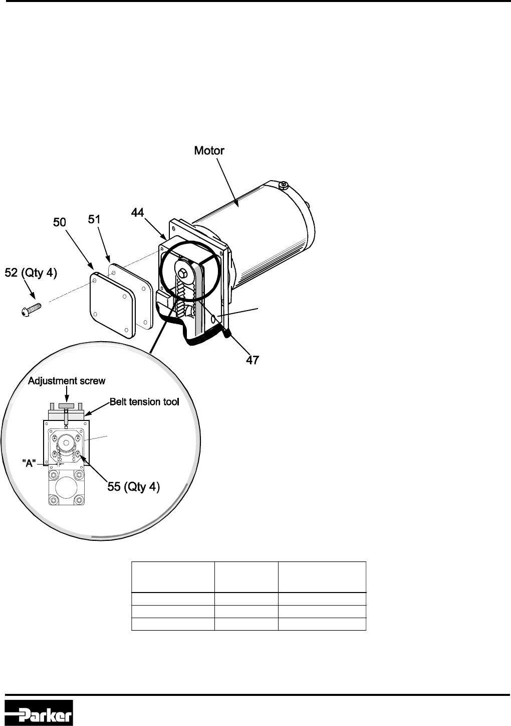
53
Adjusting Timing Belt Tension
for Parallel Mount Motors
In order to ensure long belt life and consistent performance,
it is important to tension the timing belt correctly. Too little
tension may lead to belt tooth skipping, while too much
tension adds tension to the belt and causes side loading on
both the motor and screw shafts.
Timing Belt Adjustment
(available from Parker AAD)
Belt Tensioning Procedure
1. Remove four button head cap screws (52).
2. Remove cover (50) and gasket (51) from end
cap (44).
3. Loosen four button head cap screws (55).
Loosen just enough to allow motor to move
freely.
4. Adjust belt (47) tension. Refer to Belt tension
table for deflection values. A belt with correct
tension should deflect the listed value (table
below) with the force applied at the access hole
in the housing (44) using Gates Tension Tester
(P/N 7401-0076).
• Using belt tension tool
Attach belt tension tool assembly to mounting
plate (53). Turn adjustment screw as required
to properly tension the timing belt. (Tensioning
procedure supplied with tool.)
• By hand
a. Maintaining proper tension force on the belt at
the middle of the belt span (see chart), tighten
button head cap screws (55).
b. Check for proper belt deflection.
5. Visually inspect for proper seating of belt teeth
in pulley grooves.
6. Torque the four button head cap screws (55).
(Refer to the torque values chart located on
page XX.)
7. Place gasket (51) and cover (50) on end cap
(44), securing with four button head cap screws
(52).
8. Torque the four button head cap screws (52) as
required. (Refer to the torque values chart
located earlier in this section.)
* At mid-span of belt via access hole.
Dimension "A"
Profile Deflection Force
Size Value*
32 3 mm (0.12 in) 17 N (3.7 lb)
50 3 mm (0.12 in) 25 N (5.5 lb)
80 3 mm (0.12 in) 10 N (2.2 lb)
Access Hole
Parker Hannifin Corporation
Automation Actuator Division
Wadsworth, Ohio
24
Automation
PM-ER01/USA
ER Series Rodless Actuator
Maintenance Instructions and Parts List
1. Determine type of motor (inline or parallel).
2. Referring to the appropriate illustration and specification table, assemble coupler to motor shaft using Loctite
609. Make sure to measure the “A” dimension from the mounting face of the motor. Do not measure off of the
pilot. Tighten set screw (if applicable).
3. Make sure to torque motor mounting hardware as necessary (if applicable). Refer to page 14 for torque
values.
NOTE: Use precautions contained with Loctite or any other adhesive used in assembly.
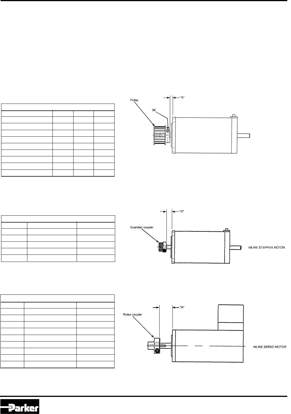
Motor Coupler and Pulley spacing
Motor coupler and pulley spacing refers to the required position of the coupler or pulley on the motor
shaft to ensure correct coupler or belt engagement.
Coupler and Pulley Spacing
Inline Servo Motors dimension “A”
Model Motor Dimension
ERB32 SM16 0.984
ERB32 SM233B* 0.450
ERB50 SM233B* 0.773
ERB50 J034x 0.852
ERB50 J092x, APEX605 & 606 0.749
ERB80 J034x 0.356
ERB80 J092x 0.218
ERB80 APEX605, 606, & 610 0.218
ERB80 APEX620 0.995
PARALLEL STEPPER MOTOR
Inline Stepper and DC Motors dimension “A”
Model Motor (Step, DC) Dimension
ERS32 S57-102, AD23A 0.331
ERS50 S57-102, AD23A 0.102
ERS50 S83-135, AD34A 0.693
ERS80 S83-135, AD34A 0.134
ERS80 S106-178, AD42A 0.528
Coupler Spacing
for Inline Driven Units
* T- shaft option
Pulley Spacing
for Parallel Driven Units
Motor ER32 ER50 ER80
S57-102, AD23A 0.176 0.193 —
S83-135, AD34A —0.190 0.255
S106-178, AD42A ——0.193
SM16x 0.364 ——
SM233* 0.176 0.193 —
J034x —0.190 0.193
J092x —0.410 0.311
APEX605,6 ——0.311
APEX610 ——0.311
Parallel Motors dimension “A”
* T- shaft option
Parker Hannifin Corporation
Automation Actuator Division
Wadsworth, OH 44281
25
Automation
ER Series Rodless Actuator
PM-ER01/USA Maintenance Instructions and Parts List
Assembly Requirements
Part Description Lubricant/Adhesive
Cylinder rod-end - Female Loctite 271
Flat Head Cap Screw Loctite 242
Set screw Loctite 242
Cylinder rod-end - Male Loctite 271
Tie rod bolt and tie rod nut Loctite 271
Apply between the tie rod
bolt and nut only.
Screw support bearing Grease
If not sealed
Fastener Adhesives
The following parts, when assembled, require the use of industrial lubricants or adhesives as indicated.
Part Numbers ER32 ER50 ER80
Description Screw Belt Size in-lb Nm Size in-lb Nm Size in-lb Nm
Roller Plate SHCS 8 8 M3 19 2.1 M4 41 4.6 M5 84 9.5
Roller Retainer FHCS (SH) 7 (10) 7 (10) M3(M4) 11(25) 1.2(2.8) M3(M4) 11(41) 1.2(4.6) M6(M6) 84(84) 9.5(9.5)
Square Rail Bearing SHCS 23 n/a M3 11 1.2 M3 11 1.2 M5 84 9.5
Bearing Locknut SHCS 37A n/a M3 11 1.2 M3 11 1.2 M4 50 4
Actuator Tie Bolts 38,40 38/40 M5,M6 85 9.6 M6,M8 210 23.7 M8,M10 415 46.9
Coupler SHCS (Servo) 11
M2,M5111.2M3111.2M4414.6
Coupler SHCS (Step/DC) 11
3/32 11 1.2 7/64 11 1.2 5/32 41 4.6
Motor Adaptor SH/FHCS 4 4 M3 11 1.2 M5 50 5.7 M6 50 5.7
Motor Mounting Bolts 11,12 211,12 2M5 50 5.7 M5,M6 50,85 5.7,9.6 M5,M6 50,85 5.7,9.6
Parallel Flange BHCS 15 15 M4 41 4.6 M5 50 5.7 M6 85 9.6
Parallel Cover BHCS 11 11 M3 11 1.2 M4 41 4.6 M5 50 5.7
Drive Pulley SHCS 11
M2,M5 11 1.2 M2,5 11 1.2 M3,M4 11,41 1.2,4.6
Load Attachment SHCS 18 18 M3 11 1.2 M4 25 2.8 M5 84 9.5
Strip Clamp BHCS 35 35 M4 25 2.8 M4 25 2.8 M4 25 2.8
Strip Guide SHCS 20 20 M3 11 1.2 M4 25 2.8 M4 25 2.8
Nut Retainer FHCS 13 13 M4 25 2.8 M4 25 2.8 M6 84 9.5
1 Not pictured; coupler parts are 9A and 9B 2 11 for inline, 12 for parallel mounting
Fastener Torque Table
Parker Hannifin Corporation
Automation Actuator Division
Wadsworth, Ohio
26
Automation
PM-ER01/USA
ER Series Rodless Actuator
Maintenance Instructions and Parts List
Bearing Carriage Adjustment
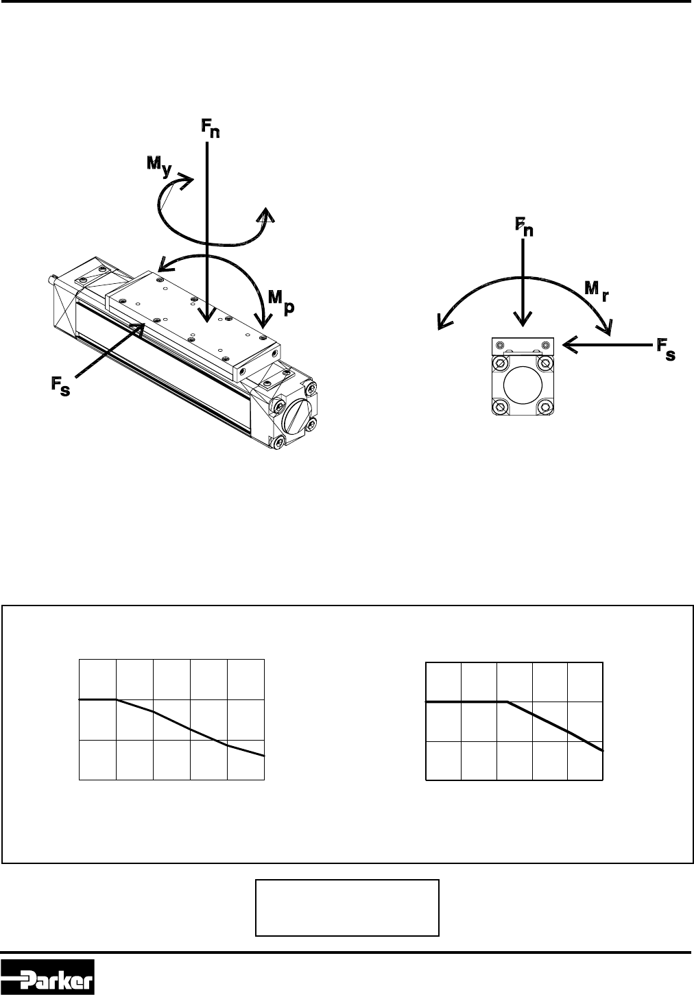
The ER Series roller bearing carriage is preloaded against normal and side loading, and pitch, yaw and roll moment
loading (as shown at right). Each of the seven roller bearing wheels consist of a quality radial bearing and Nylon
cover. This Nylon material is designed for long life and minimal distortion under load.
ER Series Roller Bearing Carriages
Key to Terms:
Fn= Normal Load
Fs= Side Load
Mp= Pitch Moment
Mr = Roll Moment
My = Yaw Moment
Calculate Effective Load (Leff):
Leff = Lact / (fsp x ftemp)
Load Considerations
It is important to consider the parameters of the application to best select an actuator. Should the actuator experi-
ence difficulties during use, it may be necessary to consider the application when searching for a cause.
Two factors limit the performance of the roller bearing carriage, speed and temperature. Under conditions of exces-
sive speed or temperature, the load capacity of the carriage should be derated as shown in the graphs to the right.
To calculate the effective load, divide the actual load by the temperature and speed factors as shown in the formula
below.
012345
0.0
0.5
1.0
1.5
Speed Factor vs Speed
fsp
Speed, m/sec (in/sec)
0 (40) (80) (120) (160) (200)
Temperature Factor vs Temperature
ftemp
Temperature, ˚C (˚F)
0 1020304050
0.0
0.5
1.0
1.5
(32) (50) (68) (86) (104) (122)
Parker Hannifin Corporation
Automation Actuator Division
Wadsworth, OH 44281
27
Automation
ER Series Rodless Actuator
PM-ER01/USA Maintenance Instructions and Parts List
Roller Bearing Carriage Preloading
When would it be necessary to preload the carriage?
Under normal operating conditions (as specified in Parker Catalog 1894), the carriage should not lose preload. A
loss of preload can result in noticable play in the carriage in any direction. Should the carriage feel "loose" in the
actuator body, follow the following procedure to reset the carriage preload.
Screw Drive Actuators
1. Disassemble the actuator.
a Detach the load from the actuator.
b Remove the load attachment plate (8 socket head cap screws).
c Loosen the screws on the strip seal clamps and carefully remove the strip seal.
CAUTION: Strip seal edges are sharp!
d Detach the motor mounting assembly. For parallel driven units, it may be necessary to loosen the
timing belt before removing the four mounting bolts that attach the entire assembly. For inline driven
units, remove the motor and coupler housing (four screws for each part).
e Remove the bolts that attach the motor-side end cap (containing the thrust bearings) to the actuator body.
f Remove the mounting bolts from the non-driven end cap.
The carriage-screw assembly should now be axially somewhat loose in the actuator body.
g Separate the non-driven end cap from the actuator body. To do this, rotate the drive screw unitl the carriage lightly
meets the end of travel at the non-driven end cap. Once there, slowly rotate the drive screw; it will act as a jacking
screw to separate the end cap from the body. The screw and bearing are held together with an adhesive, and it
may require some effort to carefully separate them.
h Remove the carriage and screw assembly from the actuator body, but do not remove the carriage from the screw!
i Procede to Preloading Procedure.
Belt-Drive Actuators
1. Disassemble the actuator.
a Detach the load from the actuator.
b Remove the load attachment plate (8 socket head cap screws).
c Loosen the screws on the strip seal clamps and carefully remove the strip seal.
CAUTION: Strip seal edges are sharp!
d Detach the belt clamps from both sides of the carriage by removing the single socket head cap screws from the
carriage.
e Remove the bolts that attach the non-driven end cap to the actuator body and remove the end cap.
f Remove the carriage from the actuator body.
g Procede to Preloading Procedure.
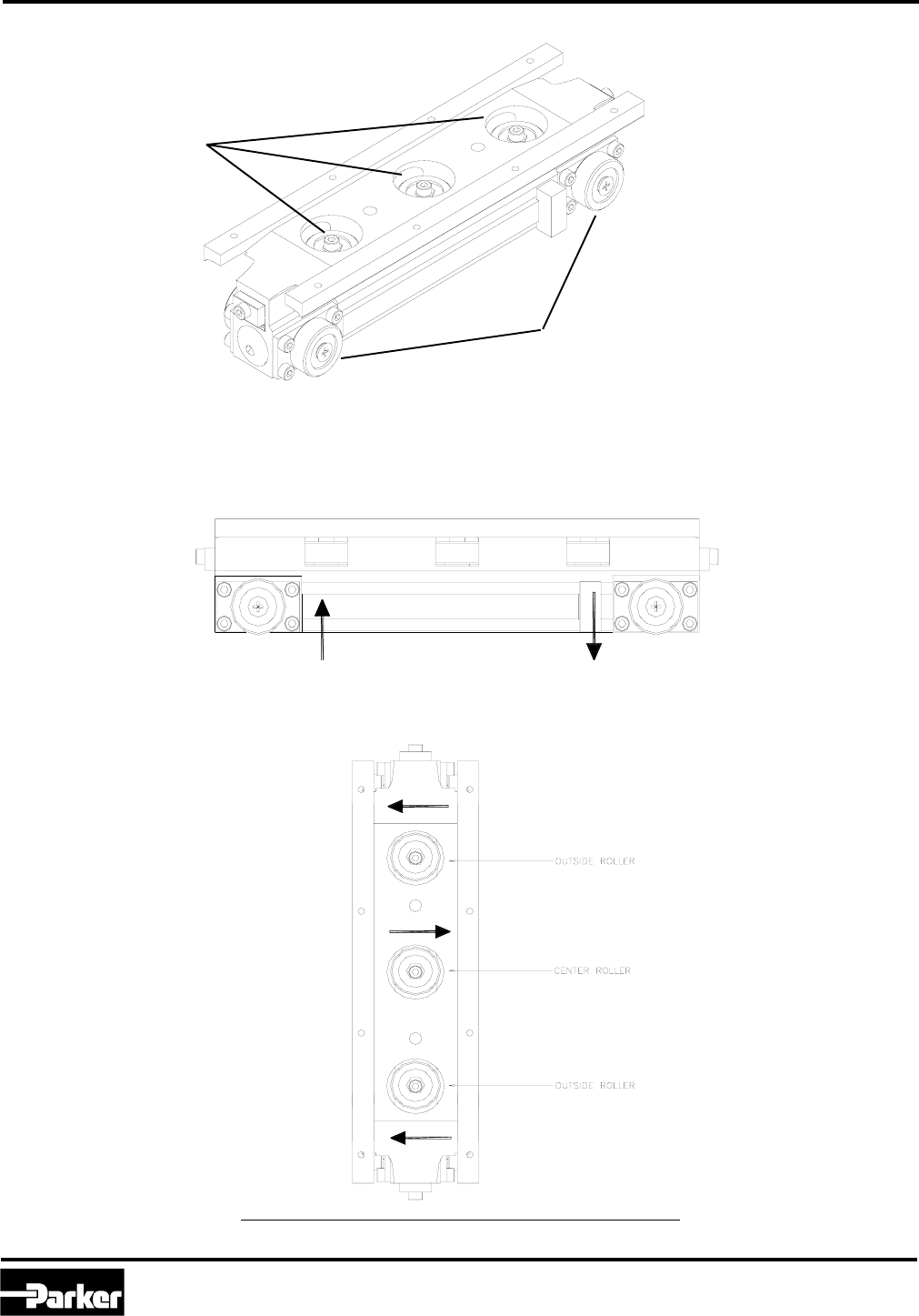
Figure 1: Actuator Components
Top: Screw Drive
Bottom: Belt Drive
Strip Seal Clamp
Strip Seal Clamp
Strip Seal Clamp
Strip Seal Clamp
Load Attachment Plates
Belt Clamp
Belt Clamp Screw

Parker Hannifin Corporation
Automation Actuator Division
Wadsworth, Ohio
28
Automation
PM-ER01/USA
ER Series Rodless Actuator
Maintenance Instructions and Parts List
Roller Bearing Carriage Preloading Procedure
1. Inspect the carriage for excess grease or contamination. Wipe off excess with a clean cloth.
2. Inspect the wheel material for any damage. If wheel material shows excessive wear, consult the factory for a
replacement.
3. Pitch/Roll (Side) Wheel Adjustment (Refer to Figure 2-a on page 29)
a. Loosen the side wheel attachment plates on both side of the carriage. Do not remove the screws.
b. With the side of the carriage facing you, push the wheel on the left upward and tighten the upper right attachment
screw. Push the wheel on the right downward and tighten the lower left screw.
c. Repeat this procedure on the other side, again moving the left wheel up and the right wheel down.
d. Set the final side wheel position by moving the carriage toward the end of the extrusion, where access to the wheels is
possible. Using a flat head screw driver, move the side wheels into contact with the appropriate edge of the slot, using
the initial settings of left wheel up and right wheel down. Hold the wheel in place against the slot with the screwdriver
and tighten the accessible plate screws.
e. Remove the carriage and tighten the remaining screws.
4. Yaw (Top) Wheel Adjustments (Refer to Figure 2-b on page 29)
a. Place the carriage in the body extrusion with the top slot facing you.
b. Preload the wheels. The top, or yaw wheels are adjusted via eccentric hex bushings. The wheels are brought into
contact with the extrusion slot by turning the eccentrics clockwise with a socket. When adjusting yaw wheels, be sure
that the two outer wheels contact the same side of the slot, while the center wheel contacts the opposite side.
Note: When mounting the actuator on its side, consider orienting the outer wheel downward to support the majority of the load.
c. Apply removable threadlocker just prior to adjusting. To tighten the wheel in place, tighten the mounting screw while
holding the eccentric bushing in place.
5.) Inspect the Carriage
a. Carriage Alignment
After all wheels have been preloaded, move the carriage back and forth to ensure that there are no alignment issues.
Also inspect the carriage to ensure that it is situated parallel to the body extrusion. Allowing the carriage to run poorly
aligned will cause premature wear on the bearings and on the strip guide bearings.
b. Magnitude of the Preload
When pulling the carriage out of the body, you should feel a slight bump when the carriage disengages. If the bump is
significant, consider readjusting.
Questions?
Call the Automation Actuator Division Electromechanical
Applications Department at (330) 336-3511
Roller Bearing Carriage Preloading
Important note: The tighter the contact with the wheels, the greater the effects of flat spots developing on the wheels at rest.
It is only necessary to have slightly firm contact between the wheel and the extrusion. Excessive preload reduces the life of the
bearings.
Parker Hannifin Corporation
Automation Actuator Division
Wadsworth, OH 44281
29
Automation
ER Series Rodless Actuator
PM-ER01/USA Maintenance Instructions and Parts List
Roller Bearing Carriage Preloading
Figure 2: Roller Bearing Carriage
Preloading Diagrams
Figure 2-a: Pitch/Roll (Side) Wheel
Preloading
Figure 2-b: Yaw (Top) Wheel
Preloading
Pitch/Roll (Side) Wheels
Yaw (Top) Wheels

Parker Hannifin Corporation
Automation Actuator Division
Wadsworth, Ohio
30
Automation
PM-ER01/USA
ER Series Rodless Actuator
Maintenance Instructions and Parts List
Making Adjustments
Square Rail Carriages
Square rail carriage units typically require no adjustment during the life of the actuator. Square rail bearing carriages
are installed prelubricated, and under catalogued operating conditions should not require additional lubrication. Once
the square rail bearing has exceeded its catalogued life, it may become necessary to replace the bearing set.
Excessive carriage play and increased friction torque are indications of bearing wear. Normally, the ball or lead
screw will end its useful life prior to the square rail bearing.
Replacement bearings are available from the Automation Actuator Division at (330) 336-3511. Please indicate the
profile size and stroke of the actuator.
Drive Belt Tensioning for Belt Drive Versions
Under normal operating conditions (as specified in Catalog 1894), the drive belt of ER Series belt driven actuators
may lose their factory set preload over time. As loss in preload may induce accuracy problems, belt slippage or
rough motion. Should this occur during use, the belt drive tension may be reset following two methods. The first
requires an inductive tension meter, available from AAD. It measures the rate of decay of the vibration of the belt
after it is struck by measuring changes in induction in the steel reinforcement strands. The second method can be
performed with simply a ruler and a weight with a known value, in which deflection of the belt is measured.
Tension Meter Method (requires Tension Meter available from AAD)
1. Remove the load attachment plate by loosening the eight screws.
2. Loosen the strip seal clamps at each end of the actuator and remove the strip seal.
3. Move the carriage to one end of the actuator; let it rest against the end of travel bumper.
4. Measure the unsupported length of the belt from the attachment clamp at the carriage to the center of the
opposite end cap.
5. Select the mass of the belt based on the actuator size: ER32- 30 g/m, ER50- 48 g/m, ER80- 75 g/m.
6. Following the instructions provided in the meter's operating manual, measure and adjust the belt tension until the
correct preload is achieved. Belt adjustments are made by turning the screw that attaches the belt clamp to the carriage.
Clockwise rotation increases tension. Once the tension has been set, move the carriage to the other end and re-
measure the belt to verify the tension. Factory tension values are: ER32- 108 N, ER50- 212 N, ER80- 336 N.
Force-Deflection Method
1. Remove the load attachment plate by loosening the eight screws.
2. Loosen the strip seal clamps at each end of the actuator and remove the strip seal.
3. Move the carriage to one end of the actuator; let it rest against the end of travel bumper.
4. Measure the unsupported length of the belt from the attachment clamp at the carriage to the center of the
opposite end cap.
5. Insert a ruler into the actuator at the center point of the unsupported belt length. Note the height of the belt on the ruler.
6. Using the values in the table below, place the required weight at the center point of the belt and measure the deflection.
Adjust the belt tension by turning the screw that attaches the belt clamp to the carriage. Clockwise rotation increases
tension. Once the appropriate deflection has been achieved, move the carriage to the other end and re-measure the belt
to verify the tension.
Actuator Series Applied Load lb (N) Belt Deflection inches (mm)
ER32 2 (9) 0.016 (0.41) x Unsupported belt length
ER50 3 (14) 0.013 (0.33) x Unsupported belt length
ER80 4 (18) 0.011 (0.28) x Unsupported belt length
Parker Hannifin Corporation
Automation Actuator Division
Wadsworth, OH 44281
31
Automation
ER Series Rodless Actuator
PM-ER01/USA Maintenance Instructions and Parts List
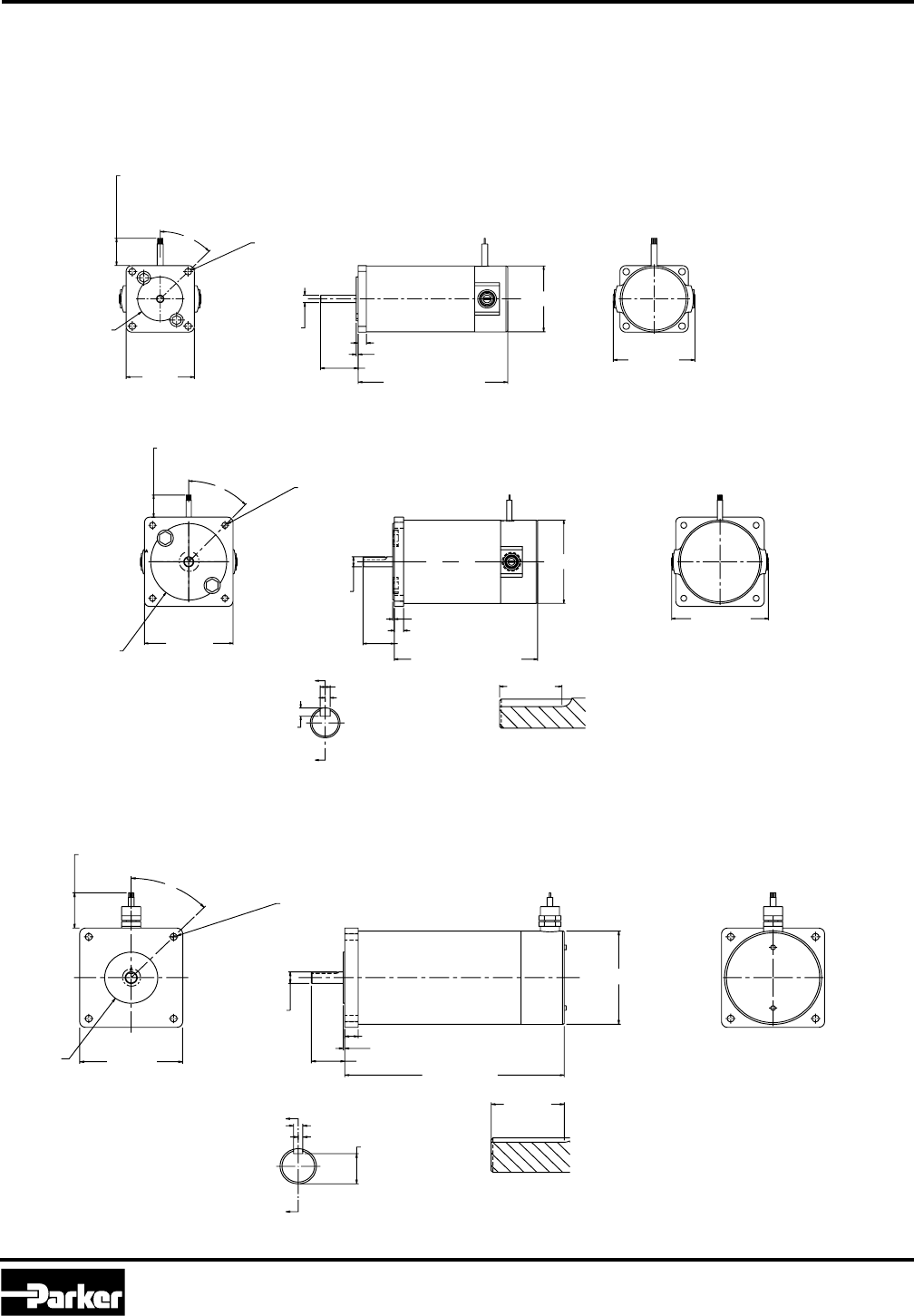
Step Motors
Step Motors
ER Series Rodless Actuators are available with premounted step motors in three frame sizes. Motor data and motor
connections are available for each size.
23 Frame Size Step Motors (S57-102 - Motor Code 21)
Model A
S57-102 4.0 (101.6)
Model A
S83-135 5.2 (129.0)
Size 34 Frame
Size 23 Frame
34 Frame Size Step Motor (S83-135 - Motor Code 31)
Dimensions: inch (mm)
Dimensions: inch (mm)
Dimensions: inch (mm)
#6-32 UNC-2B
Thd
x 6.50 (0.25) DP
(4) equally
A
30°
4.83 (0.19)
1.60
(0.063)
9.52 (0.3750)
9.51 (0.3745)
5.79 (0.228) dia
(4)
5.54 (0.218)
73.07 (2.877) dia.
72.97 (2.873)
shielded
31.24 (1.23)
29.21 (1.15)
82.55
(3.25)
max
69.34 (2.730)
69.85 (2.750)
86.36
(3.40)
Max casting size 305 (120) 8 wire
30°A
2.29 (0.09) max
1.45 (0.057)
1.70 (0.067)
15.87 (0.6250)
15.86 (0.6245)
Shaft dia
See Detail View
#6-32 UNC-2B Thd
x 6.50 (0.25) DP
(4) equally spaced
on 74.98 (2.952) BC
12.70 (0.5000)
12.69 (0.4995)
Shaft dia
35.56
(1.40)
34.54
(1.36)
#10-32 x 9.65 (0.38) DP
Mounting holes at 120°
on 76.2 (3.00) BC (3)
except 106-250 motors
106.68
(4.20)
max
88.90
(3.50)
108.20
(4.26)
dia max
155.52
(2.186) dia 13.16 (0.518)
12.70 (0.500)
dia
7.39 (0.291)
6.88 (0.271)
Holes (4)
17.53
(0.69)
3.19 (0.1255)
3.15 (0.1240)
Wide
12.17
(0.483
+0.000
-0.127
+0.000)
-0.005)
#404 Woodruff Key
Detail View33.78
(1.33)
29.72
(1.17) 0.50-14 NPT
Size 42 Frame
Model A
S106-178 195.32 (7.69)
42 Frame Size Step Motor (S106-178 - Motor Code 41)
5.481 (0.216) dia (4)
57.66
(2.27)
max
305 (120) 8 wire
shielded
47.14
(1.856)
4.953 (0.195)
on 66.67 (2.625) BC A
1.60 (0.063)
38.15 (1.502)
38.05 (1.498)
21.08 (0.83)
18.54 (0.73)
#6-32 UNC-2B Thd
x 6.50 (0.25) DP
(3) equally spaced
on 47.37 (1.865) BC
20.83 (0.82)
18.29 (0.72) 60°
6.35 (0.2500)
6.34 (0.2495)
Shaft dia. (2)
4.83 (0.19)

Parker Hannifin Corporation
Automation Actuator Division
Wadsworth, Ohio
32
Automation
PM-ER01/USA
ER Series Rodless Actuator
Maintenance Instructions and Parts List
Step Motor Options
Conduit Connector Option (Motor Codes 22 and 32)
AB
CD
E
φF
G
Motor Code A B C D E ∅∅
∅∅
∅FG
22 38.1 50.8 33.0 61.5 57.2 6.3 15.0
(1.50) (2.00) (1.30) (2.42) (2.25) (0.25) (0.59)
32 38.1 63.5 35.0 76.2 82.5 9.6 25.0
(1.50) (2.50) (1.38) (3.00) (3.25) (0.38) (1.00)
Dimensions: mm (inch)
Conduit Connector Option (Motor Code 42)
1/2 in NPS
1/2 in NPS
Parker Hannifin Corporation
Automation Actuator Division
Wadsworth, OH 44281
33
Automation
ER Series Rodless Actuator
PM-ER01/USA Maintenance Instructions and Parts List
Brad Harrison Quick Disconnect Option (Motor Codes 23 and 33)
Motor Code A B C D E ∅∅
∅∅
∅FG
23 38.1 50.8 33.0 61.5 57.2 6.3 15.0
(1.50) (2.00) (1.30) (2.42) (2.25) (0.25) (0.59)
33 38.1 63.5 35.0 76.2 82.5 9.6 25.0
(1.50) (2.50) (1.38) (3.00) (3.25) (0.38) (1.00)
Dimensions: mm (inch)
Brad Harrison Quick Disconnect Option (Motor Code 43)
Brad Harrison
Male 5 Pin Receptacle
Step Motor Cable Color Coding
Motor Codes 21, 22, 31 and 32
Color Assignment
Red A+
Black A-
Yellow A Center Tap
Blue A Center Tap
Shield Ground
White B+
Green B-
Orange B Center Tap
Brown B Center Tap
Motor Codes 41 and 42
Color Assignment
Red A+
Black A-
Shield Ground
White B+
Green B-
Motor Codes 23, 33 and 43
Color Assignment
Red A+
Red-Black A-
Green Ground
Red-White B+
Red-Orange B-
Step Motor Options
Brad Harrison
Male 5 Pin Receptacle

Parker Hannifin Corporation
Automation Actuator Division
Wadsworth, Ohio
34
Automation
PM-ER01/USA
ER Series Rodless Actuator
Maintenance Instructions and Parts List
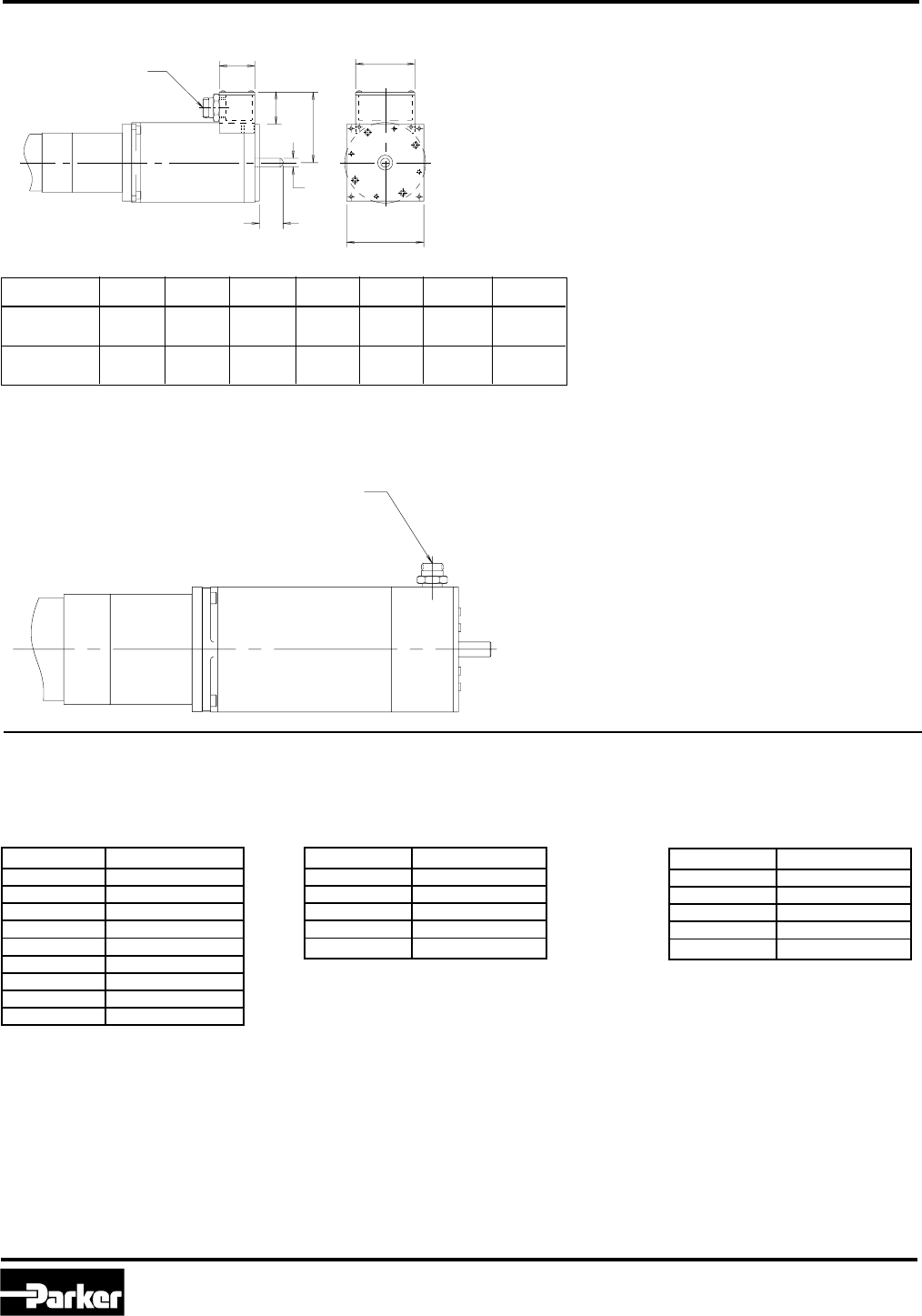
Servo Motors
Servo Motors
ER Series Rodless Actuators are available with premounted brushless servo motors in two frame sizes. Motor data
and motor connections are available for each motor.
23 Frame Size Servo Motors (SM233B - Motor Codes 22 and 23)
Dimensions: inch (mm)
5.98 (151.89)
1.25 (31.75) (SEE NOTE)
1.19 (30.23) Note: Motor Codes 22 and 23
include a 1/8 inch keyway on
the shaft.
92 mm Frame Size Servo Motors (J092n - Motor Codes J1, J2 and J3)
Dimensions: inch (mm)
Parker Hannifin Corporation
Automation Actuator Division
Wadsworth, OH 44281
35
Automation
ER Series Rodless Actuator
PM-ER01/USA Maintenance Instructions and Parts List
Servo Motors
Servo Motor Cable Color Coding
Motor Code 22
Cable Part Number:
23 TQ CABLE-10
Feedback Cable
Color Assignment
Red +5V
White A+
Yellow A-
Green B+
Blue B-
Orange Z+
Brown Z-
Black Ground
Shield Shield
Motor/ Hall Effect Cable
White-Green Hall Ground
White-Blue Hall +5V
White-Brown Hall 1
White-Orange Hall 2
White-Violet Hall 3
Yellow Motor Temp +
Yellow Motor Temp -
Red-Yellow Motor Phase A
White-Yellow Motor Phase B
Black-Yellow Motor Phase C
Green-Yellow Motor Ground
Shield Shield
Motor Code 23
Cable Part Number:
23 MS CABLE-10
Feedback Cable
Color Assignment
Red Stator 3
Black Stator 1
Green Stator 2
Blue Stator 4
Brown Rotor 1
White Rotor 2
Yellow Motor Temp +
Yellow Motor Temp -
Shield Shield
Motor Cable
Red-Yellow Motor Phase A
White-Yellow Motor Phase B
Black-Yellow Motor Phase C
Green-Yellow Motor Ground
Shield Shield
Motor Codes J1, J2 and J3
Cable Part Number:
92 RS CABLE-25
Feedback Cable
Color Assignment
Red Stator 3
Black Stator 1
Green Stator 2
Blue Stator 4
Brown Rotor 1
White Rotor 2
Yellow Motor Temp +
Yellow Motor Temp -
Shield Shield
Motor Cable
Red-Yellow Motor Phase A
White-Yellow Motor Phase B
Black-Yellow Motor Phase C
Green-Yellow Motor Ground
Shield Shield
Parker Hannifin Corporation
Automation Actuator Division
Wadsworth, Ohio
36
Automation
PM-ER01/USA
ER Series Rodless Actuator
Maintenance Instructions and Parts List
DC Brush Motors
6.99 (.275)
1.60 (0.63)
31.8 ± .13 (1.250 ± .005)
4 x ( .220 ± .005) THRU HOLES
EQUALLY SPACED ON A
(2.625) BOLT CIRCLE
∅5.59 ± .13
66.68
∅
∅
57.2 (2.25)
71.12 (2.800)
MAX
#18 AWG LEADWIRE, 10' LONG
3 WIRE SHIELDED CABLE WITH
INTERNAL CASE GROUND
45°
126.37 ± .50 (4.975 ± .020)
6.350 +.000
–.013 (.2500 )
+.0000
–.0005
57.7 (2.27)
SQUARE
∅38.10 +.000
–.050 ( 1.500 )∅+.000
–.002
4 x ( .220 ± .008) THRU HOLES
EQUALLY SPACED ON A
(3.875) BOLT CIRCLE
∅5.59 ± .20 ∅
∅98.43
#18 AWG LEADWIRE, 10' LONG
3 WIRE SHIELDED CABLE WITH
INTERNAL CASE GROUND
9.525
+.000
–.008
()
.3750
+.0000
–.0003
∅73.03
+.000
–.050
()
2.875∅
+.000
–.002
79.4 (3.13)
95.25 (3.750)
MAX
85.1 (3.35)
SQUARE
1.60 (.063)
8.89 (.350)
30.23 ± .75 (1.190 ± .030)
137.80 ± .38 (5.425 ± .015)
B
B
VIEW A
3.18 ± .03 (.125 ± .001)
1.588 (.0625)
2.67
+.00
–.38
()
.015
+.000
–.015
SECTION B-B
19.99 (.787)
Keyway Detail
45°
4 x ( .280) THRU HOLES
EQUALLY SPACED ON A
(4.950) BOLT CIRCLE
∅7.10
125.75
∅
∅
25 FOOT LONG CABLE
(MEASURED FROM REAR END BELL EXIT)
12.70
+.000
–.013
()
.5000
+.0000
–.0005
∅55.58
+.000
–.075
( 2.188 )∅
+.000
–.003
45°
101.6 (4.00)
108.0 (4.25)
SQUARE
13.97 (.550)
1.52 (.060)
35.0 ± .8 (1.38 ± .03)
230.0 (9.06) REF
SECTION B-B
VIEW A
B
B25.4 (1.00)
FULL USABLE
KEYWAY
3.20 ± .03 (.126 ± .001)
1.60 (.0630) 10.92
+.00
–.38
()
.430
+.000
–.015
Keyway Detail
DC Brush Motors
ER Series Rodless Actuators are available with premounted DC brush motors in two frame sizes. Motor data and
motor connections are available for each motor.
Dimensions in mm (inch)
42 Frame Size DC Brush Motors (AD42A - Motor Code 41)
34 Frame Size DC Brush Motors (AD34A - Motor Code 31)
23 Frame Size DC Brush Motors (AD23A - Motor Code 21)

Parker Hannifin Corporation
Automation Actuator Division
Wadsworth, OH 44281
37
Automation
ER Series Rodless Actuator
PM-ER01/USA Maintenance Instructions and Parts List
DC Brush Motor Options
Conduit Connector Option (Motor Codes 22 and 32)
AB
CD
E
φF
G
Motor Code A B C D E ∅∅
∅∅
∅FG
22 38.1 50.8 33.0 61.5 57.2 6.3 15.0
(1.50) (2.00) (1.30) (2.42) (2.25) (0.25) (0.59)
32 38.1 63.5 35.0 76.2 82.5 9.6 25.0
(1.50) (2.50) (1.38) (3.00) (3.25) (0.38) (1.00)
Dimensions: mm (inch)
Conduit Connector Option (Motor Code 42)
1/2 in NPS
1/2 in NPS

Parker Hannifin Corporation
Automation Actuator Division
Wadsworth, Ohio
38
Automation
PM-ER01/USA
ER Series Rodless Actuator
Maintenance Instructions and Parts List
DC Brush Motor Options
Brad Harrison Quick Disconnect Option (Motor Codes 23 and 33)
Motor Code A B C D E ∅∅
∅∅
∅FG
23 38.1 50.8 33.0 61.5 57.2 6.3 15.0
(1.50) (2.00) (1.30) (2.42) (2.25) (0.25) (0.59)
33 38.1 63.5 35.0 76.2 82.5 9.6 25.0
(1.50) (2.50) (1.38) (3.00) (3.25) (0.38) (1.00)
Dimensions: mm (inch)
Brad Harrison Quick Disconnect Option (Motor Code 43)
Brad Harrison
Male 3 Pin Receptacle
DC Brush Motor Cable Color Coding
Motor Codes 21, 22, 31 and 32
Color Assignment
Blue Motor +
Green/Yellow Motor Ground
Brown Motor -
Motor Codes 41 and 42
Color Assignment
Red Motor +
Green/Yellow Motor Ground
Black Motor -
Motor Codes 23, 33 and 43
Color Assignment
Black Motor +
Green/Yellow Motor Ground
White Motor -
Brad Harrison
Male 3 Pin Receptacle
Parker Hannifin Corporation
Automation Actuator Division
Wadsworth, OH 44281
39
Automation
ER Series Rodless Actuator
PM-ER01/USA Maintenance Instructions and Parts List
LOAD
_
+DC 5 - 24V
SWITCH
LOAD
_
+
SWITCH
PNP Wiring Connection
Hall Effect Sensors
NPN Wiring Connection
(BLUE)
(BROWN)
(BROWN)
(BLUE)
Two types of Hall effect sensors are available for use
with ER Series actuators. The normally open sensor is
typically used for mid-position sensing, such as homing
applications. The normally closed sensor is generally
used to indicate over-travel at the end of the stroke, and
is used in a safety circuit to prevent damage to compo-
nents caused by over-travel.
(BLACK)
(BLACK)
Specifications
Type: Solid State Type (PNP or NPN)
Switching Logic: Normally Open or Normally Closed
Supply Voltage Range: 5 - 24 VDC
Max. Switch Current: 150 mA
Current Consumption: 7 mA at 12 VDC, 14 mA at 24 VDC
Switching Response: 500 Hz Maximum
Residual Voltage: 0.8 V Maximum (150 mA)
Leakage Current: 10 uA Maximum
Insulation Resistance: 100 M Ohm min.
Min. Current for LED: 1mA
Operating Temperature: -10° to 85°C (14° to 185°F)**
Lead Termination 1500 mm (60 in) or
150 mm (6 in) with connector
Industrial Protection: IP66
Shock Resistance: 50 g's, 490 m/sec2
Note: End of travel sensors do not reduce available
stroke.
The SX, PDX, ZETA6104 and APEX 615n controls use
NPN sensors for Home and End-of-Travel.
PDX requires external +5VDC power supply for Hall
Effect Sensors.
DC 5 - 24V
BASIC CONNECTION DIAGRAM (PNP AND NPN)
Brown: DC Voltage (5-24 VDC)
Black: Limit Input
Blue: Ground
Hall Effect Sensor Ordering Information
Sensor Only
ER Series (without Clamp)
Hall Effect Sensor Information
Part No. Type LED Color Logic Cable/Connector
SMH-1P N.O. Green PNP
SMH-1N N.O. Red NPN
SMC-1P N.C. Yellow PNP
SMC-1N N.C. White/Red NPN
SMH-1PC N.O. Green PNP
SMH-1NC N.O. Red NPN
SMC-1PC N.C. Yellow PNP
SMC-1NC N.C. White/Red NPN
1.5m Black
with Leads
150mm Black
with Connector*
Hall Effect Sensor Information
Part No.** Type LED Color Logic Cable/Connector
SMHnn-1P N.O. Green PNP
SMHnn-1N N.O. Red NPN
SMCnn-1P N.C. Yellow PNP
SMCnn-1N N.C. White/Red NPN
SMHnn-1PC N.O. Green PNP
SMHnn-1NC N.O. Red NPN
SMCnn-1PC N.C. Yellow PNP
SMCnn-1NC N.C. White/Red NPN
1.5m Black
with Leads
150mm Black
with Connector*
Sensor with Clamp Included
Sensor Clamps
(Ordered Separately)
Part Number Actuator Size
SC32 ER32
SC50 ER50
SC80 ER80
* Sensor cable assemblies purchased separately.
** nn = 32, 50 or 80 to fit ER32, ER50 or ER80
* Sensor cable assemblies purchased separately.
Hall Effect Sensors
Parker Hannifin Corporation
Automation Actuator Division
Wadsworth, Ohio
40
Automation
PM-ER01/USA
ER Series Rodless Actuator
Maintenance Instructions and Parts List
Reed Switches
Reed Switches
Reed switches are available in a normally open or
normally closed configuration. The low amp switch is
suitable for connection to PLCs or other low current
devices. The high amp switch can be used to drive
sequencers, relays, coils, or other devices directly. Not
compatible with TTL level I.O. Logic (switch will work with
TTL level if wired backwards but LED will not light).
Low Amp Reed Switch Specifications
Switching Logic: Normally Open (SMR-1L)
Normally Closed (SMD-1L)
Voltage Rating: 85-125 VAC or 6-24 VDC*
(NO)
6-24 VAC, 6-24 VDC* (N.C.)
Power Rating:
AC or DC Resistive Load: 10 watts (N.O.)
AC or DC Inductive Load: 5 watts (N.O.)
AC or DC: 3 watts (N.C.)
Switching Current Range:
Resistive Load (PC, Sequencer): 5-40 mA (N.O.), 5-25 mA (NC)
Inductive Load (Relay): 5-25 mA
Minimum Current for LED: 5 mA
Switching Response: 300 Hz (N.O.), 200 Hz (NC)
Breakdown Voltage: 200 VDC
Contact Resistance: 100 M Ohm min.
Operating Temperature: -10° to 85°C (14° to 185°F)**
Lead Termination: 1500 mm (60 in) or
150 mm (6 in) with connector
Industrial Protection: IP66
Shock Resistance: 30 g's, 300 m/sec2
(Required for proper operation 24VDC)
Put Diode parallel to load (CR) with polarity as shown
below.
12VDC
+
D: Diode: select a Diode with the breakdown voltage
and current rating according to the load.
CR: Relay coil (under 0.5 W coil rating)
(Recommended for longer switch life 125VAC)
Put resistor and capacitor parallel to load (CR).
125VAC
+
CR: Relay coil (under 2 W coil ratings)
R: Resistor under 1 K Ohm
C: Capacitor 0.1 µF
C
RCR
DCR
Integral Circuit for Switching Contact Protection
(BROWN)
(BROWN)
High Amp Reed Switch Specifications
Switching Logic: Normally Open
Voltage Rating: 85-125 VAC or 6-24 VDC*
Power Rating:
AC or DC Resistive Load: 10 watts
AC or DC Inductive Load: 5 watts
Switching Current Range:
Resistive Load (PC, Sequencer): 30-300 mA
Inductive Load (Relay): 30-100 mA
Minimum Current for LED: 18 mA
Switching Response: 300 Hz Maximum
Breakdown Voltage: 200 VDC
Contact Resistance: 100 M Ohm min.
Operating Temperature: -10° to 85°C (14° to 185°F)**
Lead Termination: 1500 mm (60 in) or 150 mm
(6 in) with connector
Industrial Protection: IP66
Shock Resistance: 30 g's, 300 m/sec2
* Polarity is restricted for DC operation: (+) to Brown (-) to Blue
If these connections are reversed for TTL levels the contacts
will close, but the LED will not light. Connector versions are for
DC operation only.
** Exceeds temperature range for ET Series mechanical components.
(BLUE)
-
-
(BLUE)
DC Operation
AC Operation (1.5 m Cable with Leads Only)
Reed Switch Information
Part No. Type LED Color Rating Cable/Connector
SMR-1 N.O. Green Hi Amp
SMR-1L N.O. Red Low Amp
SMD-1L N.C. Yellow Low Amp
SMR-1C N.O. Green Hi Amp
SMR-1LC N.O. Red Low Amp
SMD-1LC N.C. Yellow Low Amp
1.5m Grey
with Leads
150mm Grey
with Connector*
*Switch cable assemblies purchased separately.
DC operation only.
** nn = 32, 50 or 80 to fit ER32, ER50 or ER80
Reed Switch Information
Part No.** Type LED Color Rating Cable/Connector
SMRnn-1 N.O. Green Hi Amp
SMRnn-1L N.O. Red Low Amp
SMDnn-1L N.C. Yellow Low Amp
SMRnn-1C N.O. Green Hi Amp
SMRnn-1LC N.O. Red Low Amp
SMDnn-1LC N.C. Yellow Low Amp
1.5m Grey
with Leads
150mm Grey
with Connector*
Switch Ordering Information
Note: Care must be taken not to exceed the Power Rating of the
switch while still observing the voltage and current limitations.
Switch Clamps (Ordered Separately)
Actuator Size ER32 ER50 ER80
Clamp Part No. SC32 SC50 SC80
Switches Only (ER Series w/o Clamp) Switches with Clamp Included
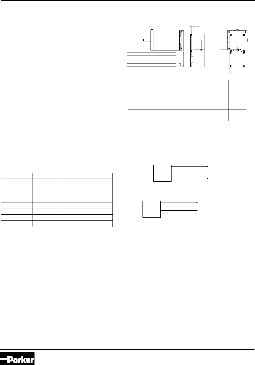
Parker Hannifin Corporation
Automation Actuator Division
Wadsworth, OH 44281
41
Automation
ER Series Rodless Actuator
PM-ER01/USA Maintenance Instructions and Parts List
Actuator Lead (in) Holding Force N (lb)
ER50-B01 1.000 735 N (165 lb)
ER50-B02 0.500 1560 N (350 lb)
ER50-B05 0.200 3560 N (800 lb)*
ER50-A05 0.200 3560 N (800 lb)*
ER80-B01 1.000 2560 N (575 lb)
ER80-B02 0.500 5120 N (1150 lb)
ER80-B04 0.250 7120 N (1600 lb)*
ER80-A04 0.250 7120 N (1600 lb)*
Brake Option (E, F, G, H)
A brake option is available on the ER Series size 50 and 80
rodless actuators to prevent back driving of the bearing
carriage when power is removed from the motor. The brake
is a spring loaded, friction disc type that requires a separate
power signal (24 VDC or 115 VAC) to the solenoid that
releases the brake. The brake option attaches directly to the
rear of the ball or Acme screw, preventing movement of the
bearing carriage for static conditions. Options which mount
to the rear of the actuator are not available with the brake
option.
Ordering Information
Specify brake option, voltage, and connector style within
complete actuator part number.
E: 115 VAC with flying leads and cable gland
F: 24 VDC with flying leads and cable gland
G: 115 VAC with Brad Harrison and 4 m cable
H: 24 VDC with Brad Harrison and 4 m cable
Notes:
•Brake option available on ET/ER50, ET/ER80, and ET/ER100.
•To be used as static brake only! Not intended for
dynamic braking.
•Contact factory for use with inline or reverse parallel
motor styles.
•Not available with mounting options that attach to rear of
cylinder, including B, C, E, H, and N.
•External power supply required when used with
Parker controls.
Specifications:
Mounting: Mechanically attached to end of lead screw
and enclosed in a sealed metal housing.
Voltage: 24 VDC or 115 VAC (to release)
Current: ER50: 24 VDC = 0.542A,
115 VAC = 0.113A
ER80: 24 VDC = 0.667A,
115 VAC = 0.139A
Holding Torque: ER50: 3.36 Nm (30 lb-in)
ER80: 11.2 Nm (100 lb-in)
Connector: Flying leads 3.5 m (12 ft) or
Brad Harrison 3 pin connector
(4 m mating cable supplied)
Cylinder A B C D E
ET/ER50 50.0 36.3 75.0 63.5 7
(1.96) (1.43) (2.95) (2.50) (.276)
ET/ER80 76.0 60.0 95.3 95.3 10
(3.00) (2.36) (3.75) (3.75) (.39)
ET100*** 82.6 66.5 136.7 127.0 10
(3.25) (2.62) (5.38) (5.00) (.39)
DIMENSIONS: mm
Inch equivalents for mm dimensions are shown in ( ).
Wiring information:
Flying lead:
Connector version:
* Figure has been truncated at maximum catalog thrust rating
of standard actuator. Consult factory for higher holding forces.
** Note: 115 VAC is rectified internally.
*** C & D dimensions exceed actuator envelope.
Dimensional Information:
C
D
E
B
A
BRAKE
Chassis Ground
115 VAC** or 24 VDC
Red/Black
Red/White
115 VAC** or 24 VDC
BRAKE Black
Black

Parker Hannifin Corporation
Automation Actuator Division
Wadsworth, Ohio
42
Automation
PM-ER01/USA
ER Series Rodless Actuator
Maintenance Instructions and Parts List
Notes

Parker Hannifin Corporation
Automation Actuator Division
Wadsworth, OH 44281
43
Automation
ER Series Rodless Actuator
PM-ER01/USA Maintenance Instructions and Parts List
Offer Of Sale
1. Terms and Conditions of Sale: All descriptions, quotations, proposals,
offers acknowledgments, acceptances and sales of Seller's products are
subject to and shall be governed exclusively by the terms and conditions
stated herein. Buyer's acceptance of any offer to sell is limited to these terms
and conditions. Any terms or conditions in addition to, or inconsistent with
those stated herein, proposed by Buyer in any acceptance of an offer by
Seller, are hereby objected to. No such additional, different or inconsistent
terms and conditions shall become part of the contract between, Buyer and
Seller unless expressly accepted in writing by Seller. Seller's acceptance of
any offer to purchase by Buyer is expressly conditional upon Buyer's assent
to all the terms and conditions stated herein, including any terms in addition to,
or inconsistent with those contained in Buyer's offer. Acceptance of Seller's
products shall in all events constitute such assent.
2. Payment: Payment shall be made by Buyer net 30 days from the date of
delivery of the items purchased hereunder. Amounts not timely paid shall bear
interest at the maximum rate permitted by law for each month or portion thereof
that the Buyer is late in making payment. Any claims by Buyer for omissions
or shortages in a shipment shall be waived unless Seller receives notice
thereof within 30 days after Buyer's receipt of the shipment.
3. Delivery: Unless otherwise provided on the face hereof, delivery shall be
made F.O.B. Seller's plant. Regardless of the method of delivery, however, risk
of loss shall pass to Buyer upon Seller's delivery to a carrier. Any delivery
dates shown are approximate only and Seller shall have no liability for any
delays in delivery.
4. Warranty: Seller warrants that the items sold hereunder shall be free from
defects in material or workmanship for a period of 18 months from date of
shipment from Parker Hannifin Corporation. THIS WARRANTY COMPRISES THE
SOLE AND ENTIRE WARRANTY PERTAINING TO ITEMS PROVIDED HEREUN-
DER. SELLER MAKES NO OTHER WARRANTY, GUARANTEE, OR REPRESEN-
TATION OF ANY KIND WHATSOEVER. ALL OTHER WAR-RANTIES, INCLUDING
BUT NOT LIMITED TO, MERCHANTABILITY AND FITNESS FOR PURPOSE,
WHETHER EXPRESS, IMPLIED, OR ARISING BY OPERATION OF LAW, TRADE
USAGE, OR COURSE OF DEALING ARE HEREBY DISCLAIMED.
NOTWITHSTANDING THE FOREGOING, THERE ARE NO WARRANTIES
WHATSOEVER ON ITEMS BUILT OR ACQUIRED WHOLLY OR PARTIALLY, TO
BUYER'S DESIGNS OR SPECIFICATIONS.
5. Limitation of Remedy: SELLER'S LIABILITY ARISING FROM OR IN ANY
WAY CONNECTED WITH THE ITEMS SOLD OR THIS CONTRACT SHALL BE
LIMITED EXCLUSIVELY TO REPAIR OR REPLACEMENT OF THE ITEMS SOLD
OR REFUND OF THE PURCHASE PRICE PAID BY BUYER, AT SELLER'S SOLE
OPTION. IN NO EVENT SHALL SELLER BE LIABLE FOR ANY INCIDENTAL,
CONSEQUENTIAL OR SPECIAL DAMAGES OF ANY KIND OR NATURE
WHATSOEVER, INCLUDING BUT NOT LIMITED TO LOST PROFITS ARISING
FROM OR IN ANY WAY CONNECTED WITH THIS AGREEMENT OR ITEMS SOLD
HEREUNDER, WHETHER ALLEGED TO ARISE FORM BREACH OF CONTRACT,
EXPRESS OR IMPLIED WARRANTY, OR IN TORT, INCLUDING WITHOUT
LIMITATION, NEGLIGENCE, FAILURE TO WARN OR STRICT LIABILITY.
6. Changes, Reschedules and Cancellations: Buyers may request to modify
the designs or specifications for the items sold hereunder as well as the
quantities and delivery dates thereof, or may request to cancel all or part of
this order, however, no such requested modification or cancellation shall
become part of the contract between Buyer and Seller unless accepted by
Seller in a written amendment to this Agreement. Acceptance of any such
requested modification of cancellation shall be at Seller's discretion, and shall
be upon such terms and conditions as Seller may require.
7. Special Tooling: A tooling charge may be imposed for any special tooling,
including without limitation, dies, fixtures, molds and patterns, acquired to
manufacture items sold pursuant to this contract. Such special tooling shall be
and remain Seller's property notwithstanding payment of any charges by Buyer.
In no event will Buyer acquire any interest in apparatus belonging to Seller
which is utilized in the manufacture of the items sold hereunder, even if such
apparatus has been specially converted or adapted for such manufacture and
notwithstanding any charges paid by Buyer. Unless otherwise agreed, Seller
shall have the right to alter, discard or otherwise dispose of any special tooling
or other property in its sole discretion at any time.
8. Buyer's Property: Any designs, tools, patterns, materials, drawings
confidential information or equipment furnished by Buyer, or any other
items which become Buyer's property, may be considered obsolete and
may be destroyed by Seller after two (2) consecutive years have elapsed
without Buyer placing an order for the items which are manufactured
using such property. Seller shall not be responsible for any loss or
damage to such property while it is in Seller's possession or control.
9. Taxes: Unless otherwise indicated on the face hereof, all prices and
charges are exclusive of excise, sales, use, property, occupational or
like taxes which may be imposed by any taxing authority upon the
manufacture, sale or delivery of the items sold hereunder. If any such
taxes must be paid by Seller or if Seller is liable for the collection of
such tax, the amount thereof shall be in addition to the amounts for the
items sold. Buyer agrees to pay all such taxes or to reimburse Seller
therefore upon receipt of its invoice. If Buyer claims exemption from any
sales, use or other tax imposed by any taxing authority, Buyer shall save
Seller harmless from and against any such tax, together with any interest
or penalties thereon which may be assessed if the items are held to be
taxable.
10. Indemnity For Infringement of Intellectual Property Rights: Seller
shall have no liability for infringement of any patents, trademarks,
copyrights, trade dress, trade secrets or similar rights except as
provided in this Part 10. Seller will defend and indemnify Buyer against
allegations of infringement of U.S. patents, U.S. trademarks, copyrights,
trade dress and trade secrets (hereinafter 'Intellectual Property Rights').
Seller will defend at its expense and will pay the cost of any settlement
or damages awarded in an action brought against Buyer based on an
allegation that an item sold pursuant to this contract infringes the
Intellectual Property Rights of a third party. Seller's obligation to defend
and indemnify Buyer is contingent on Buyer notifying Seller within ten
(10) days after Buyer becomes aware of such allegations of infringement,
and Seller having sole control over the defense of any allegations or
actions including all negotiations for settlement or compromise. If an
item sold hereunder is subject to a claim that it infringes the Intellectual
Property Rights of a third party, Seller may, at its sole expense and
option, procure for Buyer the right to continue using said item, replace or
modify said item so as to make it noninfringing, or offer to accept return
of said item and return the purchase price less a reasonable allowance
for depreciation. Notwithstanding the foregoing, Seller shall have no
liability for claims of infringement based on information provided by
Buyer, or directed to items delivered hereunder for which the designs are
specified in whole or part by Buyer, or infringements resulting from the
modification, combination or use in a system of any item sold hereunder.
The foregoing provisions of this Part 10 shall constitute Seller's sole and
exclusive liability and Buyer's sole and exclusive remedy for infringement
of Intellectual Property Right.
If a claim is based on information provided by Buyer or if the design for
an item delivered hereunder is specified in whole or in part by Buyer,
Buyer shall defend and indemnify Seller for all costs, expenses or
judgements resulting from any claim that such item infringes any patent,
trademark, copyright, trade dress, trade secret or any similar right.
11. Force Majeure: Seller does not assume the risk of and shall not be
liable for delay or failure to perform any of Seller's obligations by reason
of circumstances beyond the reasonable control of Seller (hereinafter
'Events of Force Majeure'). Events of Force Majeure shall include
without limitation, accidents, acts of God, strikes or labor disputes, acts,
laws, rules or regulations of any government or government agency,
fires, floods, delays or failures in delivery of carriers or suppliers,
shortages of materials and any other cause beyond Seller's control.
12. Entire Agreement/Governing Law: The terms and conditions set
forth herein, together with any amendments, modifications and any
different terms or conditions expressly accepted by Seller in writing,
shall constitute the entire Agreement concerning the items sold, and
there are no oral or other representations or agreements which pertain
thereto. This Agreement shall be governed in all respects by the law of
the State of Ohio. No actions arising out of the sale of the items sold
hereunder of this Agreement may be brought by either party more than
two (2) years after the cause of action accrues.
The items described in this document and other documents or descriptions provided by Parker Hannifin Corporation, its subsidiaries and its authorized
distributors are hereby offered for sale at prices to be established by Parker Hannifin Corporation, its subsidiaries and its authorized distributors. This offer
and its acceptance by any customer ("Buyer") shall be governed by all of the following Terms and Conditions. Buyer's order for any such item, when
communicated to Parker Hannifin Corporation, its subsidiary or an authorized distributor ("Seller") verbally or in writing, shall constitute acceptance of this
offer.

Parker Hannifin Corporation
Automation Actuator Division
135 Quadral Drive
Wadsworth, Ohio 44281 USA
Tel: (330) 336-3511
Fax: (330) 334-3335
Web site: http://www.parker.com/automation
Automation
