Parker Products Compax M S L Users Manual
COMPAX-M /-S (L) COMPAX_UG_V6.26_Oct_2001
COMPAX-M -S (L) to the manual 705d6290-6aa1-428d-8736-0389ca516865
2015-02-06
: Parker-Products Parker-Products-Compax-M-S-L-Users-Manual-516743 parker-products-compax-m-s-l-users-manual-516743 parker-products pdf
Open the PDF directly: View PDF ![]() .
.
Page Count: 242 [warning: Documents this large are best viewed by clicking the View PDF Link!]
- C
- Contents
- Unit assignment:
- Safety instructions
- COMPAX – CD
- Switch-on status
- Conditions for usage
- S
- Start-up manual
- Overview:
- COMPAX-M unit features
- Mains module NMD10/NMD20
- COMPAX 35XXS unit features
- COMPAX 25XXS unit characteristics
- COMPAX 45XXS/85XXS unit characteristics
- COMPAX 1000SL Unit characteristics
- Connections to the motor
- Interfaces
- Digital inputs and outputs (excluding COMPAX 1000SL)
- Digital inputs and outputs for COMPAX 1000SL
- Technical data / Connections of inputs and outputs
- Initiators and D/A monitor
- Service D/A monitor / override
- Service D/A monitor
- D/A monitor option D1
- RS232 interface
- Absolute value sensor (option A1)
- X13: Encoder interfaces, ...
- HEDA interface (option A1/A4)
- Bus connection
- Technical data
- Operating Instructions
- Overview:
- Configuration
- Configuration via PC using "ServoManager"
- Positioning and control functions
- Absolute positioning [POSA]
- Relative positioning [POSR]
- Process velocity [SPEED]
- Acceleration and braking time [ACCEL]
- Setting/resetting an output [OUTPUT]
- Setting multiple digital outputs [OUTPUT O12=1010]
- Switch off drive unit. [OUTPUT O0]
- OUTPUT O0=... in program
- Password [GOTO]
- External velocity specification. [SPEED SYNC]
- Mark-related positioning [POSR]
- Preparatory instructions
- Changes in speed within a positioning process [POSR SPEED]
- Comparators during positioning [POSR OUTPUT]
- Cam controller with compensation for switching delays
- rogrammable waiting time [WAIT]
- Program jump [GOTO]
- Sub-program jump [GOSUB]
- Instruction to end a sub-program. [RETURN]
- END instruction [END]
- Start a program loop [REPEAT]
- Branching [IF I7=1]
- Binary IF query of inputs [IF I12=101-1]
- Comparative operations
- Specific processing of data record groups. WAIT START.
- Jump with data record selection [GOTO EXT]
- Sub-program jump with data record selection [GOSUB EXT]
- Error handling [IF ERROR GOSUB]
- STOP / BREAK handling [IF STOP GOSUB xxx]
- Arithmetic
- Position monitoring (P93=1, 2, 3)
- Idle display
- Speed monitoring in speed control mode (P93="4")
- PLC sequential step tracking
- Engaging and disengaging the motor brake
- Output of variable voltage
- Optimization functions
- Interfaces
- Accessories and options
- Appendix
- Application examples
- Index
COMPAX-M /-S (L)
Subject to technical modification. 11.10.01 11:01 192-040053 N2
Data correspond to the state of technical development at the time of printing.
COMPAX User Guide
Compact Servo Controller
We automate motion
DIN EN ISO 9001
C
E
R
T
I
F
I
E
D
Q
U
A
L
I
T
Y
S
Y
S
T
E
M
Reg. Nr. 36 38
Parker Hannifin GmbH
EMD Hauser
P. O. Box: 77607-1720
Robert-Bosch-Str. 22
D-77656 Offenburg, Germany
Phone: +49 (0)781 509-0
Fax: +49 (0)781 509-176
http://www.parker-emd.com
Parker Hannifin plc
Electromechanical Division
21 Balena Close
Poole, Dorset
BH17 7DX UK
Phone: +44 (0)1202 69 9000
Fax: +44 (0)1202 69 5750
http://www.parker-emd.com
From software version V6.26 October 2001

Contents COMPAX-M / -S
2
1. Contents
1. Contents...................................................................................................2
2. Unit assignment: ....................................................................................7
3. Safety instructions.................................................................................8
3.1 General dangers........................................................................................8
3.2 Safe working practices .............................................................................8
3.3 Special safety instructions.......................................................................8
3.4 Conditions of warranty .............................................................................9
4. COMPAX – CD...........................................................................................9
5. Switch-on status...................................................................................10
5.1 Configuration when supplied.................................................................10
5.2 Commissioning .......................................................................................10
5.3 Equipment replacement..........................................................................12
6. Conditions for usage ...........................................................................13
7. Start-up manual ....................................................................................14
7.1 Overview: .................................................................................................14
7.1.1 Components required....................................................................................... 14
7.1.2 Overview of unit technology ............................................................................ 15
7.2 COMPAX-M unit features........................................................................17
7.2.1 Connector and terminal assignment............................................................... 17
7.2.2 COMPAX-M system network, NMD10 / NMD20 mains module...................... 18
7.2.3 COMPAX-M dimensions/installation ............................................................... 20
7.2.4 Connector assignment COMPAX-M ................................................................ 21
7.3 Mains module NMD10/NMD20................................................................22
7.3.1 Overview NMD................................................................................................... 22
7.3.2 Dimensions / installation.................................................................................. 22
7.3.3 NMD connector assignment............................................................................. 23
7.3.4 Technical data / power features NMD.............................................................. 23
7.4 COMPAX 35XXS unit features................................................................26
7.4.1 Plug and connection assignment COMPAX 35XXM....................................... 26
7.4.2 Installation and dimensions of COMPAX 35XXM ........................................... 27
7.4.3 Wiring COMPAX 35XXM.................................................................................... 28

3
7.4.4 COMPAX 35XXM connector assignment ........................................................ 29
7.5 COMPAX 25XXS unit characteristics ....................................................30
7.5.1 COMPAX 25XXS connector and connection assignment.............................. 30
7.5.2 COMPAX 25XXS-specific technical data......................................................... 32
7.5.3 COMPAX 25XXS dimensions / installation ..................................................... 33
7.5.4 Connector assignment COMPAX 25XXS ........................................................ 34
7.6 COMPAX 45XXS/85XXS unit characteristics ........................................35
7.6.1 Plug and connection assignment COMPAX 45XXS/85XXS........................... 35
7.6.2 COMPAX 45XXS/85XXS installation / dimensions ......................................... 36
7.6.3 COMPAX 45XXS/85XXS-specific wiring.......................................................... 37
7.6.4 COMPAX 45XXS/85XXS connector and pin assignment ............................... 39
7.7 COMPAX 1000SL Unit characteristics...................................................40
7.7.1 Connector and terminal assignment for COMPAX 1000SL........................... 40
7.7.2 Connector assignment COMPAX 1000SL (overview) .................................... 42
7.7.3 Mounting and dimensions COMPAX 1000SL ................................................. 43
7.7.4 Safety chain / emergency stop functions ....................................................... 44
7.8 Connections to the motor.......................................................................46
7.8.1 Resolver / SinCos.............................................................................................. 46
7.8.2 Additional brake control................................................................................... 51
7.9 Interfaces .................................................................................................52
7.9.1 Digital inputs and outputs (excluding COMPAX 1000SL).............................. 52
7.9.2 Digital inputs and outputs for COMPAX 1000SL............................................ 53
7.9.3 Technical data / Connections of inputs and outputs..................................... 54
7.9.4 Initiators and D/A monitor ................................................................................ 55
7.9.5 Service D/A monitor / override......................................................................... 56
7.9.6 Service D/A monitor.......................................................................................... 56
7.9.7 D/A monitor option D1 ...................................................................................... 58
7.9.8 RS232 interface ................................................................................................. 59
7.9.9 Absolute value sensor (option A1).................................................................. 59
7.9.10 X13: Encoder interfaces, ... .............................................................................. 60
7.9.10.1 Encoder interfaces / analogue rpm specification for COMPAX............ 60
7.9.10.2 Area of application of process interfaces ............................................. 60
7.9.10.3 Encoder interfaces / Analogue rpm specification / Step direction
input for COMPAX 1000SL .................................................................. 61
7.9.11 HEDA interface (option A1/A4)......................................................................... 63
7.9.12 Bus connection ................................................................................................. 63
7.10 Technical data .........................................................................................64
8. Operating Instructions...........................................................................67
8.1 Overview: .................................................................................................67
8.1.1 Block structure of the basic unit (not applicable for COMPAX 1000SL)...... 68
8.1.2 Password protection......................................................................................... 70
8.2 Configuration...........................................................................................71
8.2.1 Front plate operation (not available with COMPAX 1000SL)......................... 71
8.2.2 Configuration when supplied........................................................................... 72

Contents COMPAX-M / -S
4
8.2.3 Configuration process...................................................................................... 72
8.2.4 Safety instructions for initial start-up ............................................................. 73
8.2.5 Configurationparameters ................................................................................. 74
8.2.6 Absolute value function with standard resolver ............................................ 79
8.2.7 Machine zero mode........................................................................................... 80
8.2.8 Limit switch operation ...................................................................................... 89
8.3 Configuration via PC using "ServoManager".......................................91
8.3.1 Installing ServoManager................................................................................... 91
8.3.2 Configuring COMPAX ....................................................................................... 91
8.3.3 Individual configuration of synchronous motors........................................... 91
8.4 Positioning and control functions.........................................................95
8.4.1 Absolute positioning [POSA]........................................................................... 96
8.4.2 Relative positioning [POSR]............................................................................. 96
8.4.3 Process velocity [SPEED] ................................................................................ 97
8.4.4 Acceleration and braking time [ACCEL] ......................................................... 97
8.4.5 Setting/resettingan output [OUTPUT] ............................................................. 98
8.4.6 Setting multiple digital outputs [OUTPUT O12=1010]................................... 98
8.4.7 Switch off drive unit. [OUTPUT O0]................................................................. 98
8.4.8 OUTPUT O0=... in program............................................................................... 98
8.4.9 Password [GOTO] ............................................................................................. 99
8.4.10 External velocity specification. [SPEED SYNC] ............................................. 99
8.4.11 Mark-related positioning [POSR]................................................................... 100
8.4.12 Preparatory instructions................................................................................. 101
8.4.13 Changes in speed within a positioning process [POSR SPEED] ............... 101
8.4.14 Comparators during positioning [POSR OUTPUT] ...................................... 103
8.4.15 Cam controller with compensation for switching delays............................ 104
8.4.16 Programmable waiting time [WAIT]............................................................... 107
8.4.17 Program jump [GOTO].................................................................................... 107
8.4.18 Sub-program jump [GOSUB].......................................................................... 107
8.4.19 Instruction to end a sub-program. [RETURN] .............................................. 107
8.4.20 END instruction [END] .................................................................................... 107
8.4.21 Start a program loop [REPEAT]..................................................................... 108
8.4.22 Branching [IF I7=1].......................................................................................... 108
8.4.23 Binary IF query of inputs [IF I12=101-1] ........................................................ 108
8.4.24 Comparative operations ................................................................................. 109
8.4.25 Specific processing of data record groups. WAIT START. ......................... 109
8.4.26 Jump with data record selection [GOTO EXT] ............................................. 109
8.4.27 Sub-program jump with data record selection [GOSUB EXT] ................... 110
8.4.28 Error handling [IF ERROR GOSUB]............................................................... 110
8.4.29 STOP / BREAK handling [IF STOP GOSUB xxx] .......................................... 111
8.4.30 Arithmetic ........................................................................................................ 113
8.4.30.1 Parameter assignments ..................................................................... 113
8.4.30.2 Arithmetic and variables..................................................................... 114
8.4.31 Position monitoring (P93=1, 2, 3) .................................................................. 117
8.4.32 Idle display....................................................................................................... 119
8.4.33 Speed monitoring in speed control mode (P93="4") ................................... 120
8.4.34 PLC sequential step tracking......................................................................... 122
8.4.35 Engaging and disengaging the motor brake ................................................ 123
8.4.36 Output of variable voltage.............................................................................. 124

5
8.5 Optimization functions .........................................................................125
8.5.1 Optimization parameters ................................................................................ 127
8.5.2 Speed monitor................................................................................................. 132
8.5.3 Optimization display ....................................................................................... 133
8.5.4 External position localization with position adjustment ............................. 136
8.6 Interfaces ...............................................................................................138
8.6.1 Digital inputs and outputs.............................................................................. 138
8.6.1.1 Digital inputs and outputs for COMPAX 1000SL................................ 140
8.6.1.2 Free assignment of inputs and outputs.............................................. 143
8.6.1.3 COMPAX virtual inputs ...................................................................... 145
8.6.1.4 I/O assignment of variants ................................................................. 147
8.6.1.5 Function of inputs............................................................................... 148
8.6.1.6 Synchronous STOP using I13............................................................ 151
8.6.1.7 Function of outputs ............................................................................ 153
8.6.1.8 Diagrams:........................................................................................... 154
8.6.2 PLC data interface (function not available with COMPAX 1000SL)............ 156
8.6.3 RS232 interface ............................................................................................... 160
8.6.3.1 Interface description........................................................................... 160
8.6.3.2 Interface functions.............................................................................. 162
8.6.3.3 Read and write program sets and parameters................................... 163
8.6.3.4 Binary data transfer using RS232 ...................................................... 166
8.6.4 Process coupling using HEDA (Option A1 / A4)........................................... 168
9. Accessories and options..................................................................173
9.1 System concept.....................................................................................173
9.2 Overview ................................................................................................174
9.3 Motors ....................................................................................................176
9.4 HAUSER linear actuators .....................................................................177
9.5 Data interfaces.......................................................................................178
9.5.1 RS232 ............................................................................................................... 178
9.5.2 Bus systems.................................................................................................... 178
9.5.2.1 Interbus-S / Option F2........................................................................ 178
9.5.2.2 RS485 / Option F1/F5........................................................................ 178
9.5.2.3 Profibus / option F3............................................................................ 178
9.5.2.4 CAN - Bus / Option F4 ....................................................................... 178
9.5.2.5 CANopen / Option F8......................................................................... 178
9.5.2.6 CS31system bus / Option F7 ............................................................. 178
9.6 Process interfaces ................................................................................179
9.6.1 Encoder interface............................................................................................ 179
9.6.2 Absolute value sensor (A1)............................................................................ 183
9.6.3 High resolution SinCos sensor system (S1/S2)
......................................... 183
9.6.4 Option S3 for linear motors............................................................................ 184
9.6.5 HEDA interface................................................................................................ 185
9.6.6 D/A monitor (D1) (option not available with COMPAX 1000SL) ................. 185
9.6.7 Analogue speed specification (E7) (option not available with COMPAX
1000SL) ............................................................................................................ 186
9.7 Accessories ...........................................................................................187

Contents COMPAX-M / -S
6
9.7.1 External control panel (not available for COMPAX 1000SL) ....................... 187
9.7.2 Terminal module for COMPAX 1000SL (EAM).............................................. 188
9.7.3 EAM5/01: DC feed for COMPAX-M................................................................. 189
9.7.4 EMC measures ................................................................................................ 191
9.7.4.1 Power filter......................................................................................... 191
9.7.4.2 Motor output throttle........................................................................... 192
9.7.5 External ballast resistors................................................................................ 193
9.7.6 ServoManager ................................................................................................. 200
9.7.7 Hand-held terminal.......................................................................................... 200
9.8 Appendix: COMPAX components.......................................................206
10.Appendix ..............................................................................................207
10.1 Status values of the standard unit (COMPAX XX00)..........................207
10.2 Additional COMPAX measuring quantites..........................................210
10.3 COMPAX parameter ..............................................................................212
10.3.1 VP parametercan be modified "On Line"..................................................... 212
10.3.2 COMPAX standard parameters...................................................................... 212
10.3.3 Monitoring and limitation characteristics..................................................... 222
10.4 Error handling and error messages ....................................................223
11.Application examples ........................................................................226
11.1.1 Overview .......................................................................................................... 226
11.1.2 External data record selection....................................................................... 227
11.1.3 Mark-referenced positioning.......................................................................... 229
11.1.4 Speed step profiling / comparator switching points.................................... 231
11.1.5 SPEED SYNC................................................................................................... 233
11.1.6 Speed control mode........................................................................................ 234
11.1.7 Fast start.......................................................................................................... 236
11.1.8 Implementing a torque controller .................................................................. 237
12.Index .....................................................................................................238
The parameter and program memory are created using ZP-RAM. This memory is
unaffected by mains power failure.
This module has a guaranteed service life of 10 years (calculated from the first
start-up).
ZP-RAM failure causes data loss; COMPAX contains wild data.
If you encounter problems of this kind, contact HAUSER.
SinCos is a registered trademark of Firma Stegmann.
Data security

General dangers
7
2. Unit assignment:
This documentation applies to the following units:
!
!!
!COMPAX 10XXSL
!
!!
!COMPAX 25XXS
!
!!
!COMPAX 45XXS
!
!!
!COMPAX 85XXS
!
!!
!COMPAX P1XXM
!
!!
!COMPAX 02XXM
!
!!
!COMPAX 05XXM
!
!!
!COMPAX 15XXM
!
!!
!COMPAX 35XXM
XX: Unit variants
e.g.: COMPAX 0260M:
COMPAX: name
02: performance class
60: Variant e.g. "00": Standard model
"60": electronic transmission
M: unit type "M": multi-axis model
"S": single-axis unit
...
The type plate is located on the upper side of the unit and contains the
following:
equipment
name
part numberserial number
option name
038106 0001 951-160101 Compax 0260M
E2
Please check the software version of your unit.
Despite all efforts on our part, software modifications may change procedures as
well as cause functional changes.
Please notify us immediately if you detect unexplainable problems when using a
new software version.
Key to unit
designation
HAUSER type plate
Notes for repeat
customers
regarding
modified software
versions:

Safety instructions COMPAX-M / -S
8
3. Safety instructions
3.1 General dangers
General dangers when safety instructions are not complied with
The unit described contains leading edge technology and is operationally reliable.
However, hazards may occur if the unit is employed incorrectly or for improper use.
Energized, moving or rotating parts can
! cause fatal injury to the user
! cause material damage
Proper use
This unit is designed for use in high voltage units (VDE0160). This unit automates
motion processes. The ability to switch several units at once makes it possible to
combine several motion processes. Reciprocal interlocks must be installed in such
cases.
3.2 Safe working practices
The unit must be operated by skilled staff only.
! When used in this manual, the term "trained staff" refers to people who,
• due to their training, experience and knowledge of current standards,
guidelines, accident prevention regulations and operating conditions, have
received authorization from the head of health and safety at the site to perform
the necessary activities, while recognizing and avoiding any associated dangers
(definition of personnel as per VDE105 or IEC364)
• are familiar with first aid and the on-site safety equipment,
• have read and observed the safety instructions
• have read and observed the User Guide (or the section which applies to the
tasks to be executed).
This applies to all tasks relating to set-up, start-up, configuration, programming and
modification of the operating conditions, operating modes and maintenance.
Please note in particular the functions contained in the start-up manual relating to
operational readiness and emergency stop.
The User Guide must be present at the unit at all times.
3.3 Special safety instructions
! Check the arrangement of unit and documentation.
! Never disconnect the electrical connections when energized.
! Use safety equipment to ensure that moving or rotating parts cannot be touched.
! Ensure that the unit is in perfect working order before operation.
! Include the operational readiness and emergency stop functions of the unit (see
start-up manual) in the safety and emergency stop functions of your machine.
! Only operate unit with the front cover attached.
! Ensure mains module has sufficient nominal and peak power ratings.
! Ensure that the unit arrangement enables the units with higher power ratings to
be fitted more closely to the power unit than the units with lower ratings
(COMPAX-M).
! Ensure that motors and linear drive units (if available) are sufficiently secured.
! Ensure that all energized connectors cannot be touched. The unit carries
voltages ratings of up to 750V, which could fatally injure the operator.
! Please mind the limits of the mechanical equipment connected.

Conditions of warranty
9
3.4 Conditions of warranty
! The unit must not be opened.
! Do not make any alterations to the unit, except for those described in the User
Guide.
! Only activate inputs, outputs and interfaces as described in the User Guide.
! When installing units, ensure that the heat sinks receive sufficient ventilation.
! Secure units as per the assembly instructions contained in the start-up manual
using the securing bores provided for this purpose. We cannot assume any
responsibility for any other methods used for securing the units.
Note on option exchange
In order to check hardware and software compatibility, it is necessary for COMPAX
options to be changed at the factory.
4. COMPAX – CD
On the accompanying CD, you will find all instructions for COMPAX and the
operating software "ServoManager".
Once the CD is inserted in a Windows – computer, the HTML desktop (default.htm)
is normally automatically started – if an Internet browser is present. If you do not
have an Internet browser on your computer, please install a version: the software is
usually available to download free of charge.
If the desktop does not start automatically, please execute the file "default.htm"
(e.g. by double clicking on the file or via "Start":"Run"). The "default.htm" file is
located directly on the CD (not in the sub-directory).
Use Language selection (top right in window) to select the language required.
Follow the CD instructions shown on the window in the center of the screen.
Use the list on the left-hand side to select the required instructions or software.
Switch-on status COMPAX-M / -S
10
5. Switch-on status
5.1 Configuration when supplied
When supplied, COMPAX is not configured. Parameter P149 is set to "0":
P149="0": COMPAX is not configured and switches to OFF mode when switched
on (24V DC and operating voltage) (motor switched off). In addition to
this, when switched on, all parameters (apart from bus settings P194,
P195, P196 and P250) are set to their default values.
P149="1": COMPAX is configured and once switched on (24V DC and operating
voltage) tries to engage the motor.
5.2 Commissioning
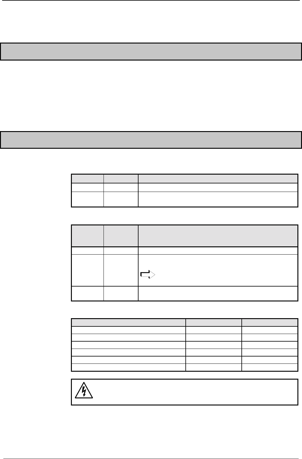
Meaning of LEDs on the front panel
COMPAX-M / -S
LED Color Meaning, when switched on
Ready green 24V DC present and initialization complete
Error red COMPAX - Error (E1...E56) present or COMPAX is
initialized.
Mains module
LED
red
Error
LED
green
Ready
Possible errors
off on no errors
on off Heat sink temperature too high or
error in logic voltage (24V DC too low or unit is defective)
Emergency stop is activated and ready contact is
released.
on on Ballast switching unit overload or
undervoltage (<100V DC or <80V AC).
COMPAX 1000SL
Status Red LED (H2) Green LED (H1)
24V not available off off
24V are switched on, boot up on off
Unit OFF off blinking
Unit error; drive switched off on blinking
Unit error; drive powered on on
Unit RUNNING off on
Caution!
If there is no control voltage, no displays will appear to indicate
that operating voltage is present.
With Error E40, external enabling is missing with COMPAX 45XXS, COMPAX
85XXS and COMPAX 1000SL (Hardware input).
Note:
Commissioning
11
After 24V DC of control voltage is switched on, COMPAX has two statuses
available once the initialization phase has been completed:
1. COMPAX is OFF
COMPAX is not configured (P149="0") or
with COMPAX XX70:
I12="0" (final stage blocked).
Now configure COMPAX (e.g. using the ServoManager / ParameterEditor).
Set P149="1"
Configuration is accepted with VC and VP of COMPAX.
2. COMPAX displays error E57
COMPAX is configured (P149="1"). However, operating voltage is not present.
Check COMPAX configuration* .
Alterations are accepted with VC and VP of COMPAX.
*) Configuring
a) Using ServoManager:
P149="1", VP and VC are transferred when being downloaded to COMPAX
from the ServoManager.
b) Using hand-held terminal:
P149="1", VP and VC are generated by the hand-held terminal.
c) Without an auxiliary device, e.g. a terminal:
P149="1", VP and VC must be transmitted after COMPAX configuration.
Switch on operating voltage
With E57: acknowledge error by pressing Enter.
When OFF: command: "OUTPUT O0=0" or
switch 24V DC on / off
Motor is powered; COMPAX display shows "RUN".
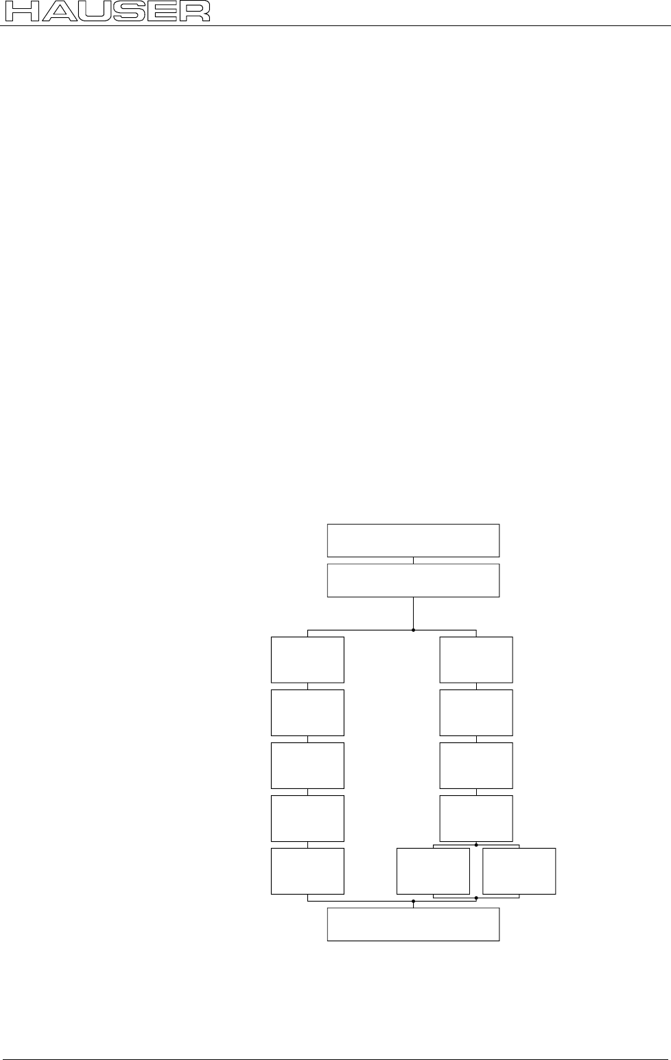
Flow chart:
connection of control
voltage 24 V DC
initializing stage
COMPAX configured
(P149="1") COMPAX not configured
(P149="0")
error E57
in COMPAX
display
OFF in
Display
check
configuration execute
configuration
VC, VP P149="1",
VC, VP
connect
DC bus
voltage
clear
error E57 24V DC
ON / OFF
connect
DC bus
voltage
OUTPUT
O0="0"
RUN
motor enabled

Switch-on status COMPAX-M / -S
12
5.3 Equipment replacement
Previous software ≥
≥≥
≥V2.0
! Procedure for copying the complete COMPAX setting onto a new unit
! Start ServoManager.
! Connect old COMPAX via RS232.
! Use menu "Insert: Axis: From controller" to set up an axis which contains all
COMPAX settings (all parameters: including system parameters, data records
and (with COMPAX XX70) existing curves).
! Connect new COMPAX.
! Use menu "Online: Download" to transfer data (without system parameters1) into
the new COMPAX.
Transferring system parameters
! Call up ParameterEditor (Menu: PC Tools: ParameterEditor)
! Use menu "Online: Copy" menu to transfer all parameters (including system
parameters) to COMPAX.
Previous software ≤
≤≤
≤V2.0
Procedure for copying the complete COMPAX setting onto a new unit
! Start ServoManager.
! Connect old COMPAX via RS232.
! Use menu "Insert: Axis: New" to set up a new axis.
! Use menu "Online: Upload" to load all COMPAX settings (all parameters:
including system parameters, data records, and (in COMPAX XX70) existing
curves) into the new axis.
! Connect new COMPAX.
! Use menu "Online: Download" to transfer data (without system parameters) into
the new COMPAX.
Transferring system parameters
! Call up ParameterEditor (Menu: PC Tools: ParameterEditor)
! Use menu "Online: Copy" menu to transfer all parameters (including system
parameters) to COMPAX.
1 System parameters are internal parameters; you will only obtain an identical
COMPAX – setting if these are also transferred.
Equipment replacement
13
6. Conditions for usage
- for CE-compliant operation in industrial and
business sectors -
The EU guidelines on electromagnetic compatibility 89/336/EEC and electrical
means of production for use within particular voltage limits 73/23/EEC are satisfied,
if the following peripheral conditions are complied with.
Only operate the units in the condition in which they are supplied, i.e. with all
housing plates and the front cover.
COMPAX P1XXM, COMPAX 02XXM, COMPAX 05XXM and COMPAX 15XXM
may only be operated with HAUSER mains modules (NMD10 or NMD20) or on
COMPAX 35XXM.
A power filter is required in the power line. The filtering can be executed
once for the entire system or as separate process for each unit.
The following power filters are required for standalone operation:
NMD10 / COMPAX 45XXS / COMPAX 85XXS: Order No.: NFI01/02
NMD20: Order No.: NFI01/03
COMPAX 35XXM: Order No.: NFI01/04 or /05
COMPAX 25XXS: Order No.: NFI01/01 or /06
COMPAX 10XXSL: Order No.: NFI01/01 or /02
Length of connection: connection between power filter and unit: unscreened: < 0.5m
screened: < 5m
Only operate the unit with a HAUSER motor and resolver cable (with
connectors containing special surface screening).
In such cases, the following cable lengths are permitted.
Motor cable < 100m (the cable must not be rolled up)
For motor lines of >20m, a motor output throttle must be used
Up to 16A nominal motor current: Type: MDR01/01 16A / 2mH.
Between 16A and 30A: Type: MDR01/02 30A / 1.1mH.
Over 30A nominal motor current: Type: MDR01/03 >30A /
0.64mH.
Resolver cable < 100m
Operation with HAUSER motors.
Only operate with calibrated controller (avoid feedback oscillation).
! The filter housing, the mains module and the COMPAX must be surface
connected with good metal conductivity and low inductivity to the cabinet ground.
! Never secure the filter housing or the unit to coated surfaces.
! Ensure that you have largest spacing possible between the signal and load lines.
! Signal lines must never pass sources of strong interference (motors,
transformers, relays,...).
! Only use accessories recommended by HAUSER (absolute value sensor,
encoder,...).
Provide large surface contact areas down both sides of all cable screening.
This is a product of the restricted sales class as per IEC 61800-3. In a domestic
environment, this product may cause high frequency disturbances, in which case
the user can be requested to implement suitable measures.
Power filter:
Motor and
resolver cable:
Motors:
Control:
Earthing:
Cable laying:
Accessories
Warning:

Start-up manual COMPAX-M / -S
14
7. Start-up manual
Compact Servo Controller
7.1 Overview:
7.1.1 Components required
In addition to a COMPAX, you will require the following
components for a COMPAX application:
! a motor with or without a transmission.
! mains supply.
! emergency stop circuit.
! various cables for connecting components.
! motor cable and resolver cable.
! supply line for voltage supply.
! supply line for 24V DC control voltage.
! hand-held terminal or PC (with RS232 cable)
containing the ServoManager program for
configuring COMPAX.
Overview:
Overview of unit technology
15
Unit
hardware
Connector
assignment / cable
Technical dataConfigurationPositioning and
control functions
Optimization
functions
InterfacesAccessories /
options
StatusParameterError list
7.1.2 Overview of unit technology
COMPAX-M and COMPAX-S
!
!!
!work with the same firmware,
yet have differences with regard to
!housing and assembly technology and
!power areas.
The following table shows the main features of the range of available units
Interfaces: 16 (8 with COMPAX 1000SL) digital inputs/outputs,
RS232; machine zero, limit switch, override input
Fieldbus options: RS485, Interbus-S, Profibus, CS31, CAN – Bus,
CANopen, HEDA (synchronous serial realtime interfaces)
Other options (excluding COMPAX 1000SL): absolute encoder sensor; encoder
input; encoder simulation; D/A monitor
Supply via central mains module: NMD10 / NMD20: Up to max. 3*500V AC
Dimensions (DxHxW): COMPAX P1XXM:
340*400*60 [mm]
COMPAX-M:
340*400*85 [mm]
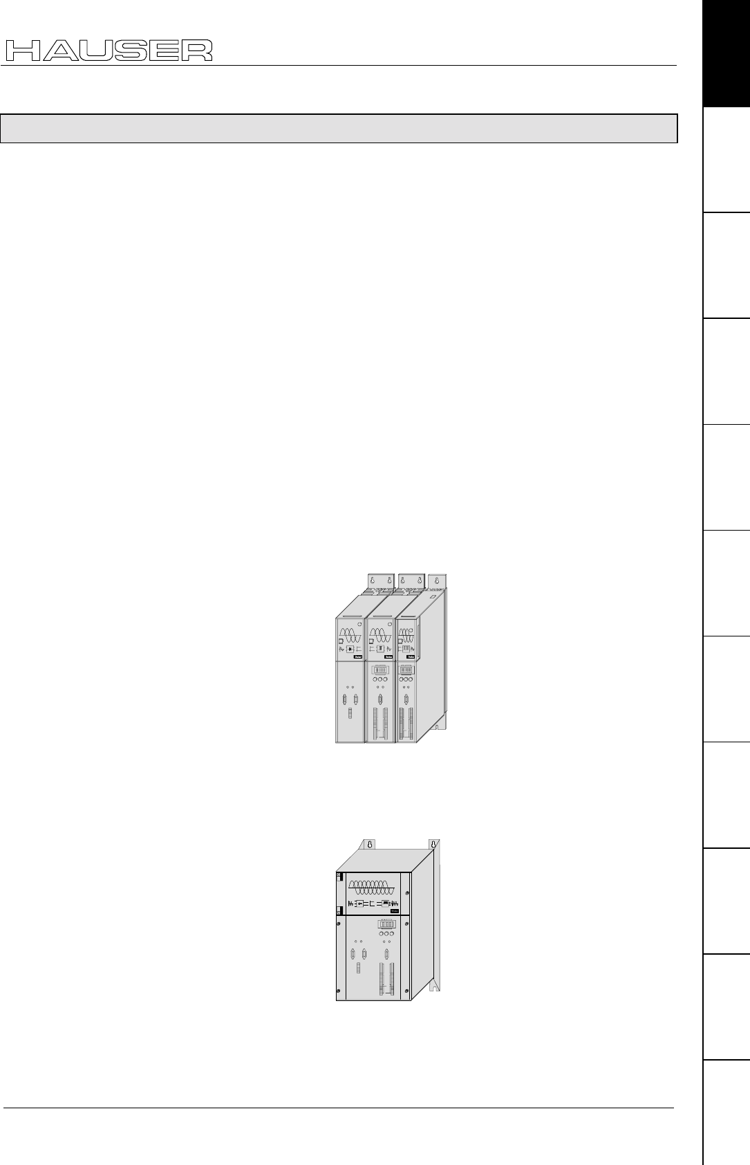
Design:
COMPAX-M with NMD
mains module
Installation: in series
X6 X7
X8
Ready Error
RS485IN OUT
Control
Status Number
X6
X8 X10
-+Enter
Ready Error
RS232
Input
Output
Test
Control
X9 X11
Value
DIGITAL
Power Supply COMPAX-M
Status
Number
X6
X8
X10
-
+
Enter
Ready
Error
RS232
Input
Output
Test
Contr ol
X9
X11
Value
DIGITAL
COMPAX-M
Power:
COMPAX ...
P1XXM: 3.8 kVA
02XXM: 4.5 kVA
05XXM: 8.0 kVA
15XXM: 17 kVA
Supply Up to max. 3 * 500V AC (integrated power unit)
Dimensions (DxHxW): 40 * 400 * 220 [mm]
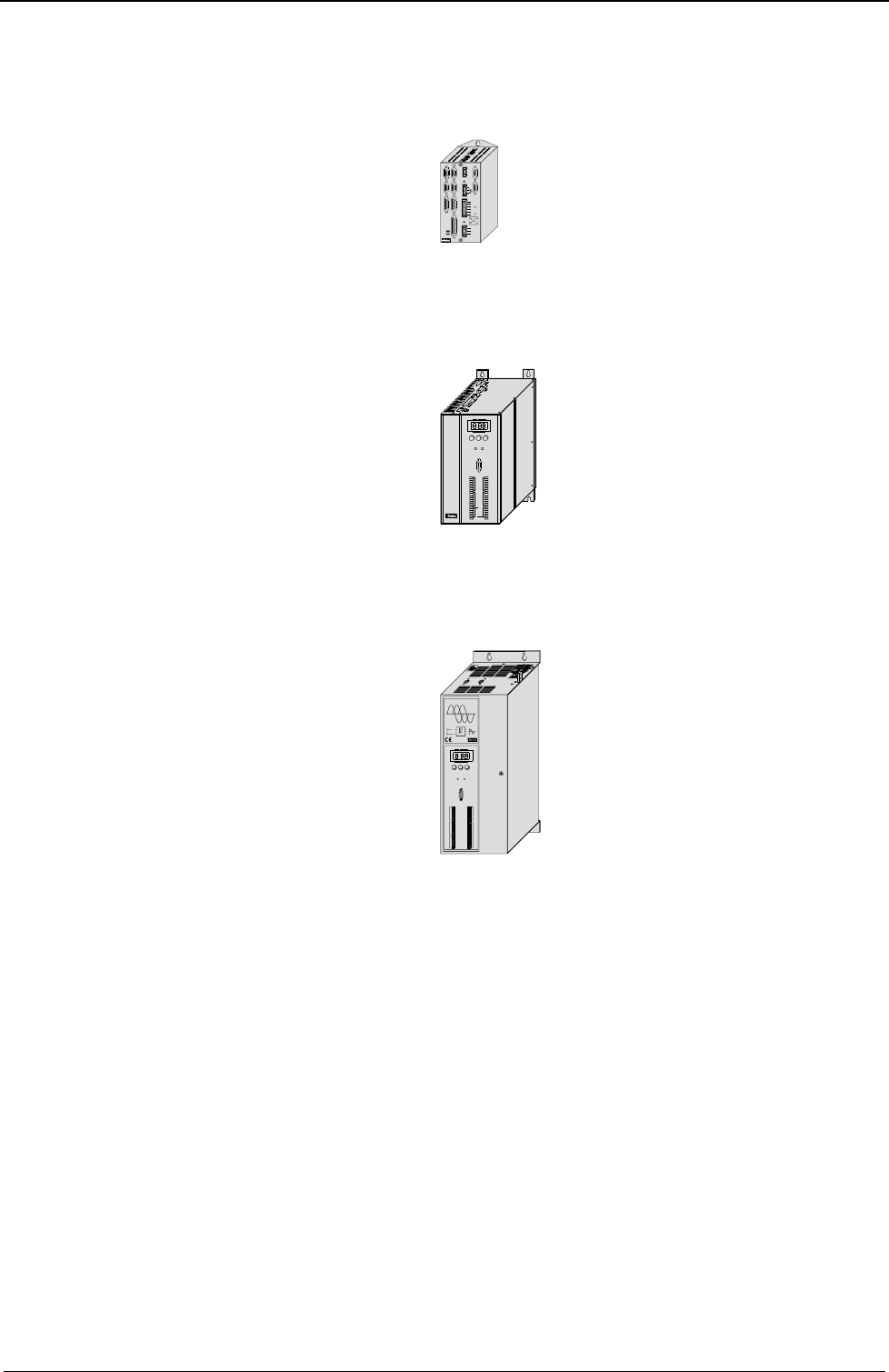
Design:
Digital
COMPAX-M
Automation
X6 X7
X8
Ready Error
RS485IN OUT
Control
Status Number
X6
X8 X10
-+Enter
Ready Error
RS232
Input
Output
Test
Control
X9 X11
Value
Power
35.0 kVA
Common function
characteristics:
COMPAX P1XXM
COMPAX 02XXM
COMPAX 05XXM
COMPAX 15XXM
COMPAX 35XXM
Start-up manual COMPAX-M / -S
16
Supply Up to max. 1*250V AC (integrated power unit)
Dimensions (DxHxW): 146*180*85 [mm]
Design:
RDump
Input
+-
Fieldbus In
Encoder
Input / Output Resolver Fieldbus Out Limit Switch
24 V DC
H2
H1
RS232 X6X5X13
X12 X17
X19
X2 X1 X4 X3
X14 X15
HEDA Out HEDA In
L1 N PE UV
WPE + -
Motor Brake
PE
230 V AC
COMPAX - SL
X7
Power
1 kVA
Supply Up to max. 1 (3)*250V AC (integrated power unit)
Dimensions (DxHxW): 220*240*130 [mm]
Design:
Status Number
X6
X8 X10
-+Enter
Ready Error
RS232
Input
Output
Test
Control
X9 X11
Value
COMPAX-S
Motion & Co ntrol
Power
2.5 kVA
Supply Up to max. 3*500V AC (integrated power unit)
Dimensions (DxHxW): 275*350*125 [mm]
Design:
X11X9
Input
Output Output
Input
Test Control
X10
X6
X8
RS232
Ready Error
ENTER+-
Value
Status Number
COMPAX-S
DIGITAL
Power
4.5 kVA
8.6 kVA
COMPAX 1000SL
COMPAX 25XXS
COMPAX 45XXS
COMPAX 85XXS
COMPAX-M unit features
Connector and terminal assignment
17
Unit
hardware
Connector
assignment / cable
Technical dataConfigurationPositioning and
control functions
Optimization
functions
InterfacesAccessories /
options
StatusParameterError list
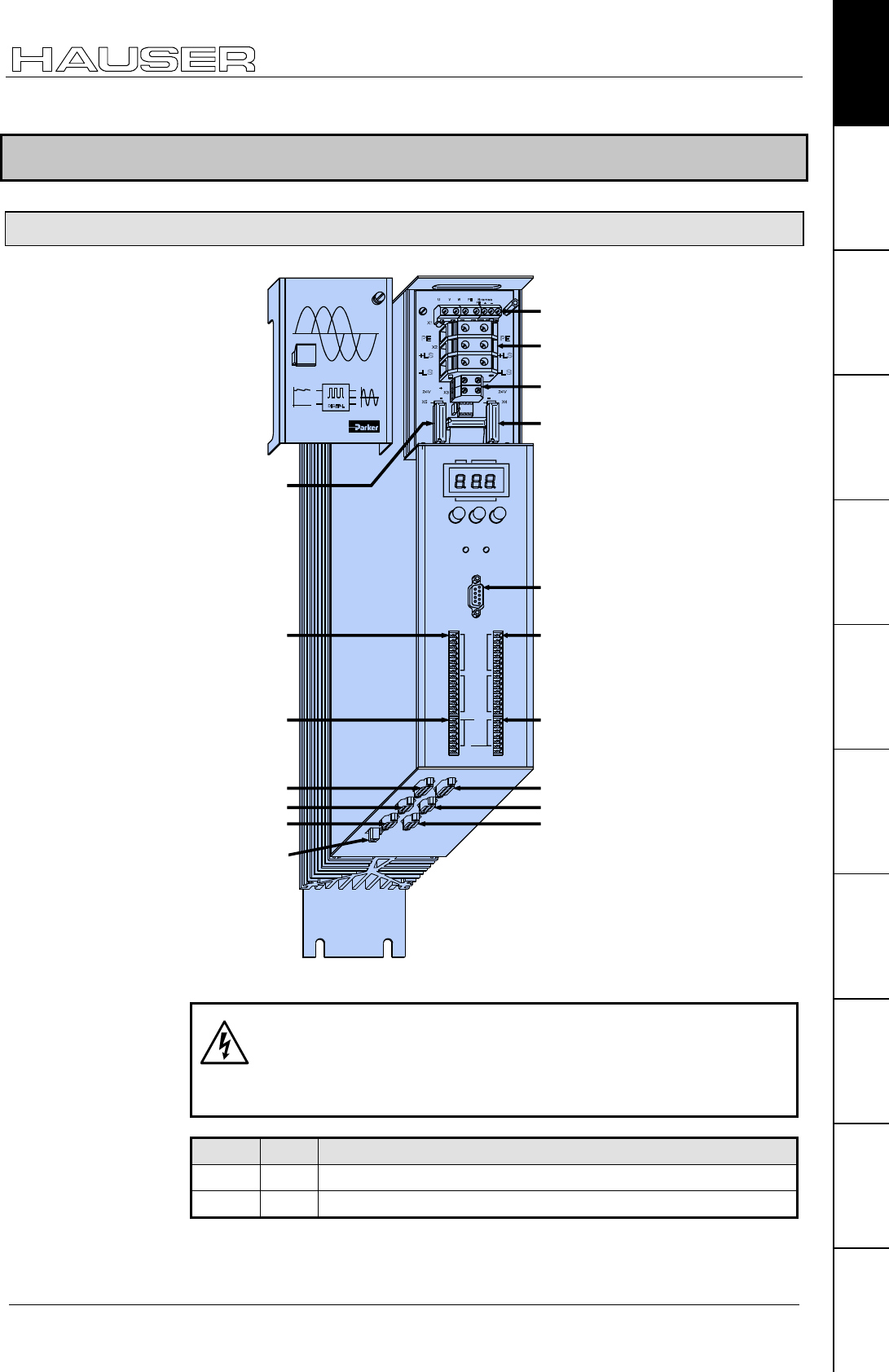
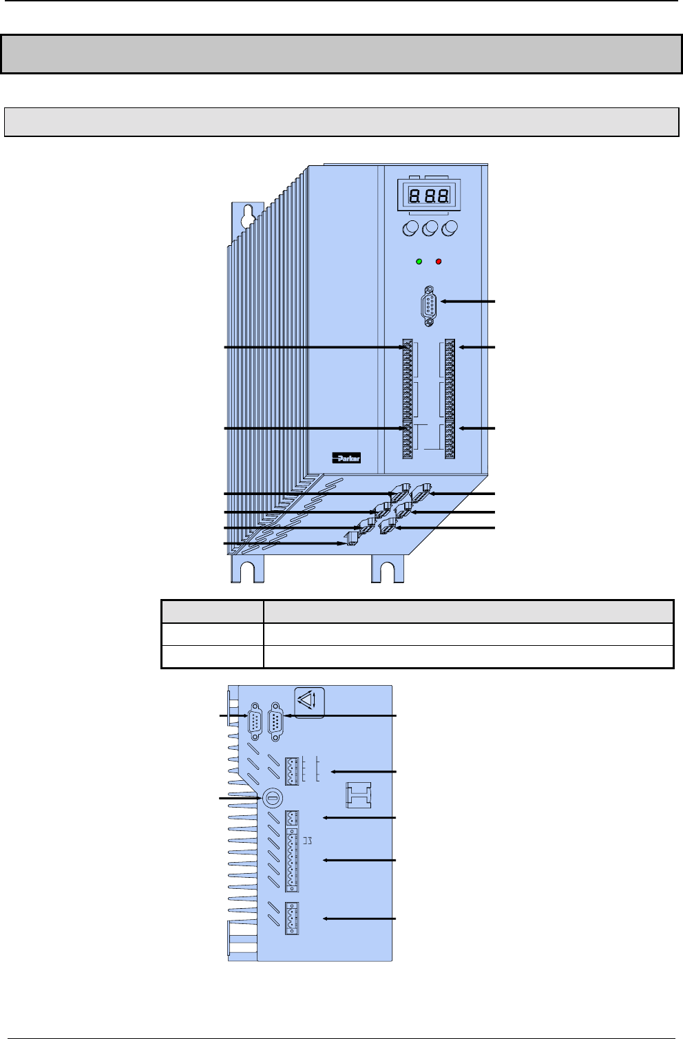
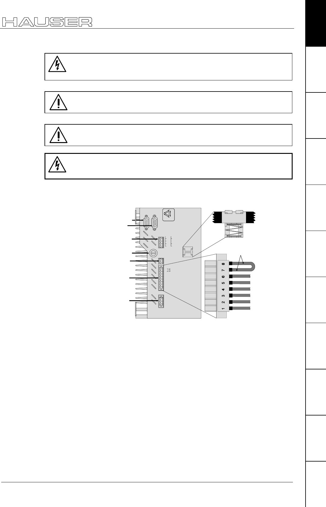
7.2 COMPAX-M unit features
7.2.1 Connector and terminal assignment
X2 intermediate loop
power connections
X3 24V control voltage
X4 control- and status
signals / bus signals
or short circuit plug
X13 Encoder
COMPAX-M
X6
Inp u t
Output
Status
Value
+- Enter
Ready Error
RS 232
Test
Control
X8 X10
X9 X11
Number
X1 motor
X5 control- and
status- signal
bus-signals
input
X6 RS232
X10 Input / Output
X11 Control
X8 Input
/ Output
X9 Test
X12 resolver
X14 HEDA
X16 absolute
encoder
X18 fan
X15 HEDA
X17 initiators
Before wiring up, always de-energize the unit.
Even once the mains supply has been switched off,
dangerous levels of voltage can remain in the system for
up to 5 min.
LED Color Meaning, when switched on
Ready green 24V DC present and initialization complete
Error red COMPAX - fault (I1...E56) present.
Meaning of LEDs on
front plate
Start-up manual COMPAX-M / -S
18
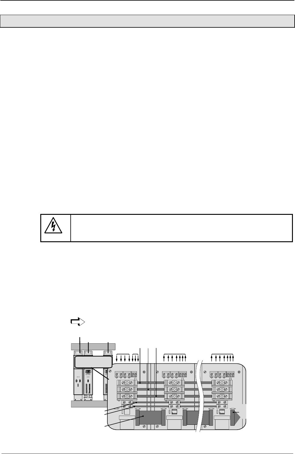
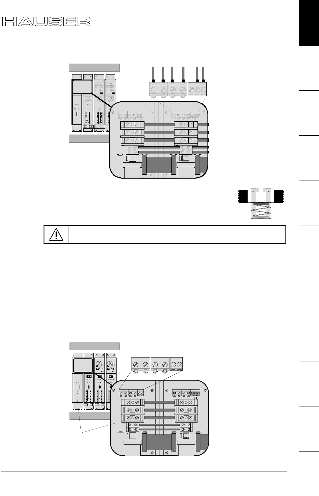
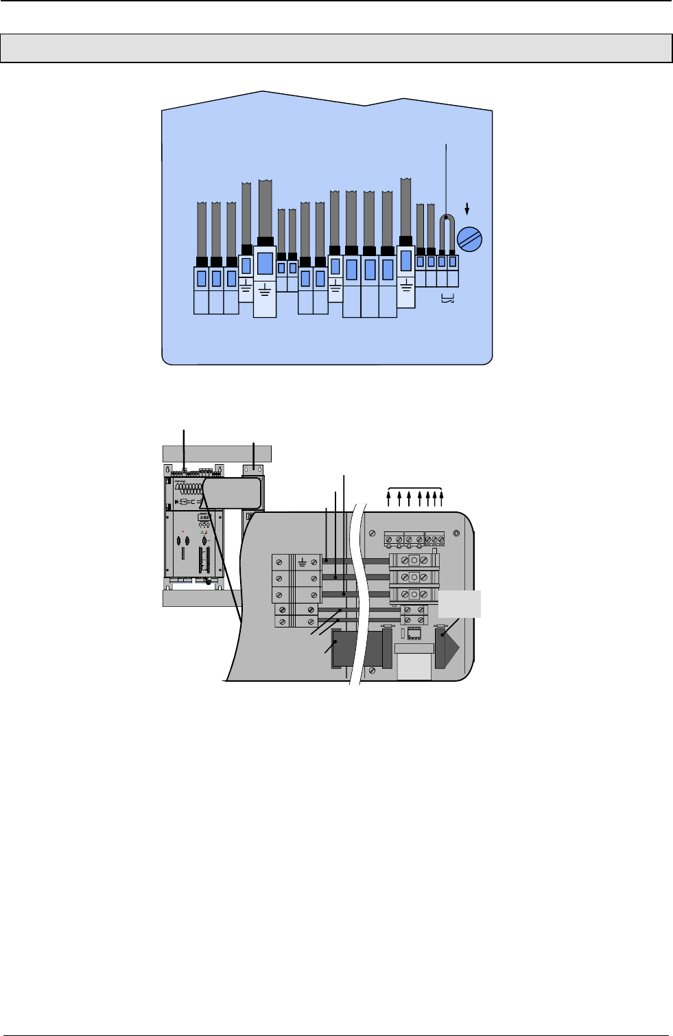
7.2.2 COMPAX-M system network, NMD10 / NMD20 mains module
A COMPAX-M drive system consists of one mains module and one or more drive
controllers. The units are coupled with one another with flatband cables (see
below). These are arranged behind the front plate cover of the power unit and the
drive controller.
The power unit converts mains power (up to 3 * 500V AC) into DC current for the
intermediate circuit.
The two connectors for connection to the bus systems are located on the front
plate of the power unit. The connection assignment complies with the specifications
for 2-cable remote bus.
The 24V DC control voltage required by the system network is supplied from the
power unit.
A connector terminal on the front of the power unit is used for connecting the
control and status signals (EMERGENCY STOP, readiness) which you can
incorporate in the control of the entire system.
These signals and the bus lines are connected internally via a preformed
doublesided flatband cable. These cables are included with the drive controller.
The connectors which receive these connection cables are housed under the front
plate cover of the mains module and the drive controller.
Attach a short circuit connector to the outgoing connector on the drive controller
that is furthest away from the mains module. The short circuit connector (order No.
102-908000) is included with the mains module.
Installation arrangement
Before wiring up, always de-energize the unit.
Even once the mains supply has been switched off, dangerous
levels of voltage can remain in the system for up to 5 min.
The wires required for creating the system network are included in the delivery.
Open the front cover (upper section of front side) by loosening the top right knurled
screw and wire up the following:
! 24V DC voltage supply.
! PE and DC current.
! Emergency stop, ready and bus signals with a terminating connector on the last
unit.
From the mains module to the individual COMPAX-M.
When delivered, the terminating connector is located on the mains module.
HAUSER
COMPAX-M
DIGITAL
Status Number
X6
X8 X10
-+Enter
Ready Error
RS232
Input
Output
Test
Control
X9 X11
Value
HAUSER
COMPAX-M
DIGITAL
Status
Number
X6
X8
X10
-
+Enter
Ready
Error
RS232
Input
Output
Test
Control
X9
X11
Value
cable conduit
HAUSER
POWER SUPPLY
X6 X7
X8
Ready Error
RS485IN OUT
Control
power supply module
COMPAX-M COMPAX-M
main 24V motor
...
motor
L1 L2L3 PE 24V
+-
24V+
-
PE
+LS
-LS
X1
X2
X3
X4
UVWPEbrake
PE+ -
X5
X1
X2
X3
X4
UVWPEbrake
PE+ -
X5
X1
X2
X3
X4
PE LS+ LS-
{
voltage supply
24V
emergency stop,
stand by and bus
signals
last device
equiped
with
terminal
plug
Short circuit
connectors
Wiring up the
system network
COMPAX-M unit features
COMPAX-M system network, NMD10 / NMD20 mains module
19
Unit
hardware
Connector
assignment / cable
Technical dataConfigurationPositioning and
control functions
Optimization
functions
InterfacesAccessories /
options
StatusParameterError list
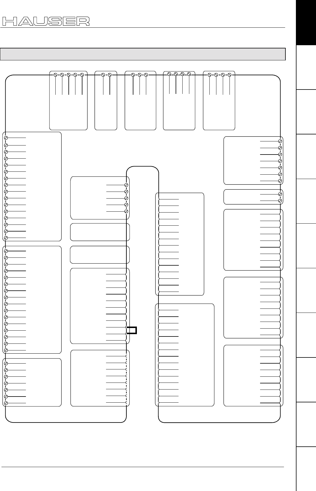
Unit side
HAUSER
POW ER SUPPLY
X6 X7
X8
ReadyError
RS485INOUT
Control
HAUSER
CO MPAX- M
DIGITAL
StatusNumber
X6
X8 X10
-+Enter
ReadyError
RS232
Input
Output
Test
Control
X9 X11
Valu e
DIGITAL
StatusNumber
X6
X8 X10
-+Enter
ReadyError
RS232
Input
Output
Test
Control
X9 X11
Valu e
COMPA X-M
Motion & Control
COMPA X-M
Motion & Control
DIGITAL
StatusNumb er
X6
X8 X10
-+Enter
ReadyError
RS232
Input
Output
Test
Control
X9 X11
Valu e
cable conduit
L1L2L3PE 24V
+-
24V+
-
PE
+LS
-LS
UVWPEbrake
PE + -
X1
X2
X3
X5
X1
X2
X3
X4X4
UVWPE
PE +-
X1
123 45
black 1
black 2
black 3
green/
yellow
free
black 4
black 5
brake
Note the screened connection of the motor cable on the
upper unit side.
Clamp the motor cable with the open place of the screen
braid under the ground terminal (see figure on the right).
Only wire up brake in motors which have a holding brake! If not, do not
wire.
The mains supply and the control voltage supply are provided by the mains
module.
Power supply:
! 3*80V AC – max. 3*500V AC; 45 - 65Hz
! Fuse protection:
NMD10: 16A (K circuit breaker in 20A)
NMD20: 35A
K circuit breaker or similar Neozed
fusible cut-out.
Control voltage
! 24V DC ±10%
Ripple <1VSS
Fuse protection: max. 16A
COMPAX-M
Motion & Control
COMPAX-M
Motion & Control
HAUSER
POWER SUPPLY
X6 X7
X8
Ready Error
RS485IN OUT
Control
HAUSER
COMPAX-M
DIGITAL
Status Number
X6
X8 X10
-+Enter
Ready Error
RS232
Input
Output
Test
Control
X9 X11
Value
DIGITAL
Status Number
X6
X8 X10
-+Enter
Ready Error
RS232
Input
Output
Test
Control
X9 X11
Value
DIGITAL
Status Number
X6
X8 X10
-+Enter
Ready Error
RS232
Input
Output
Test
Control
X9 X11
Value
cable conduit
L1 L2 L3 PE 24V
+-
24V+
-
PE
+LS
-LS
UVWPEbrake
PE+ -
X1
X2
X3
X5
X1
X2
X3
X4X4
power supply
module
L1 L2 L3 PE
+-
X1
123 45
24V
Wiring up the
motor
Screened
connection
Wiring up mains
power / control
voltage
Start-up manual COMPAX-M / -S
20
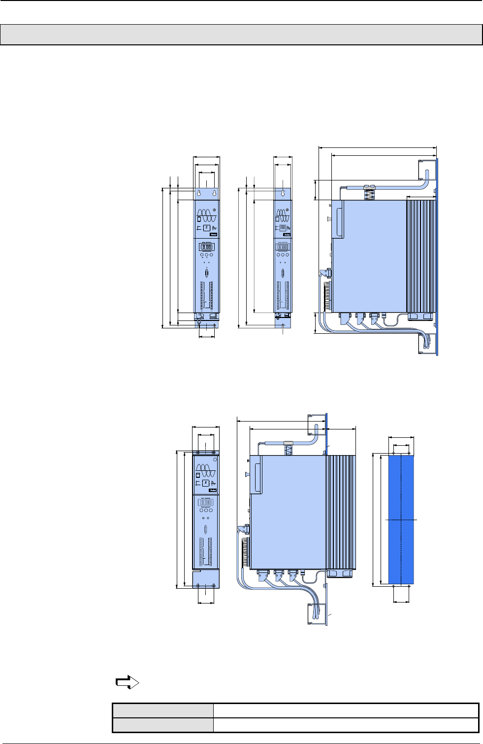
7.2.3 COMPAX-M dimensions/installation
The specific design of the COMPAX-M controller allows for wall installation
(distance: 61mm in COMPAX P1XXM and 86mm in larger units) in two different
ways.
Direct wall installation and dimensions of COMPAX-M and the mains
modules.
31
85
75
50
10
40
450
430
364
50
390
340
96
65
Attach with four 6-mm
hex-socket-head-screws
Status Number
X6
X8
X10
-
+
Enter
Ready Error
RS232
Input
Output
Test
Control
X9
X11
Value
DIGITAL
60
49
10
40
450
430
364
02XXM, 05XXM,
15XXM, NMD10
& NMD20
P1XXM
COMPAX-M
DIGITAL
Statu s Number
X8 X10
Enter
Ready Error
RS232
Input
Output
Test
Control
Value
COMPAX-M
Attach with two 6-mm
hex-socket-head-screws
65
The controllers are attached to the mounting plate with the back of the heat sink.
Indirect wall installation of COMPAX 02XXM, COMPAX 05XXM and COMPAX
15XXM and the mains modules NMD10 and NMD20.
50
50
82
424
408
Status Number
X6
X8 X10
-
+
Enter
Ready Error
RS232
Input
Output
Test
Control
X9 X11
Value
DIGITAL
50
441,5
424
85
50
COMPAX-M
294
244 96
mounting
plate
mounting
plate
The heat sink is pushed back through a hole in the panel (on right of diagram). A
separate heat chamber is created between the installation plate and the rear wall
of the control cabinet. The angles required under designation MTS2 must be
complied with.
Indirect wall installation is not possible with COMPAX P1XXM.
Units with fan: COMPAX P1XXM, COMPAX 05XXM, COMPAX 15XXM
Units without fan: COMPAX 02XXM, NMD10, NMD20
Direct
wall installation:
Indirect
wall installation:
Fan configuration
COMPAX-M unit features
Connector assignment COMPAX-M
21
Unit
hardware
Connector
assignment / cable
Technical dataConfigurationPositioning and
control functions
Optimization
functions
InterfacesAccessories /
options
StatusParameterError list
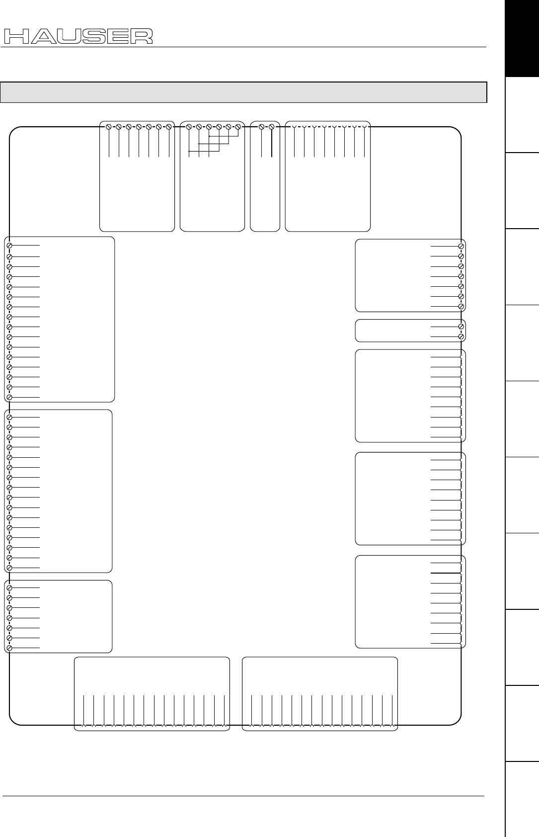
7.2.4 Connector assignment COMPAX-M
X12/1 housing
X12/2 +8V
X12/3 NC
X12/4 REF-
X12/5 SIN-
X12/6 NC
X12/7 GND
X12/8 ST+
X12/9 +5 V
X12/10 TEMP
X12/11 COS-
X12/12 COS+
X12/13 SIN+
X12/14 REF+
X12/15 ST-
X13/1 housing
X13/2 N2
X13/3 B2
X13/4 A2
X13/5 N1
X13/6 B1
X13/7 A1
X13/8 +5V
X13/9 N2/
X13/10 B2/
X13/11 A2/
X13/12 N1/
X13/13 B1/
X13/14 A1/
X13/15 GND
X10/1 I9
X10/2 I10
X10/3 I11
X10/4 I12
X10/5 I13
X10/6 I14
X10/7 I15
X10/8 I16
X10/9 O9
X10/10 O10
X10/11 O11
X10/12 O12
X10/13 O13
X10/14 O14
X10/15 O15
X10/16 O16
X9/1 +24V
X9/2 GND
X9/3 reserviert
X9/4 reserviert
X9/5 24V*
X9/6 15V - 24V emergency
stop*
X9/7 housing
X14(15)/1
NC
X16/1
T-
X17/6
GND
X17/7
Sig.MN
X17/8
Sig. E2
X17/9
Sig. E1
X14(15)/2
RxC
X14(15)/3
TxC
X14(15)/4
RxD
X14(15)/5
TxD
X14(15)/6
RxC/
X14(15)/7
TxC/
X14(15)/8
RxD/
X14(15)/9
TxD/
X16/2
NC
X16/3
D-
X16/4
NC
X16/5
GND
X16/6
T+
X16/7
NC
X16/8
D+
X16/9
+24V
X17:
DA-monitor
initiators
X14/X15:
HEDA
X16:
Absolut
encoder
X13: encoderX12: resolver / SinCos
X9
X10:
input /
output
I9...I16
O9...O16
X8/1 I1
X8/2 I2
X8/3 I3
X8/4 I4
X8/5 I5
X8/6 I6
X8/7 I7
X8/8 I8
X8/9 O1
X8/10 O2
X8/11 O3
X8/12 O4
X8/13 O5
X8/14 O6
X8/15 O7
X8/16 O8
X17/1
DA-channel 0
X18/-
0V
X18/+
24V
X11/4
DA-channel 2
X11/3
Override
X11/2
GND
X11/1
+24V
X11/5
DA-channel 3
X11/6
Override (old)
X11/7
shield
X17/2
DA-channel 1
X17/3
shield
X17/4
GND 24V
X17/5
+24V
(option D1)
X11
X18: fan
X8:
input /
output
I1...I8
O1...O8
* can be
parameterized
X1/2
V
PE
+LS
-LS
X3/1
+24 V
X3/2
0V
X6/2
RxD
X6/3
TxD
X6/4
DTR
X6/5
GND
X6/6
DSR
X6/7
RTS
X6/8
CTS
X6/9
+5V
X1/1
U
X1/3
W
PE
PE
X1/4
Br-
X1/5
Br+
X1:
motor
brake
X2:
power inter-
mediate loop
X3:
control
voltage
X6:
RS232
The assignment of X12 does not apply for the S3 option.
The bus connections are made via the mains module.
Start-up manual COMPAX-M / -S
22
7.3 Mains module NMD10/NMD20
The mains module ensures the supply of current to the COMPAX-M (not COMPAX
35XXM) axis controller and the SV drive connected into the network. It is
connected to the 3-phase power supply with 3 * 400V AC and PE. 24V DC voltage
must be provided for the control electronics.
7.3.1 Overview NMD
L1 L2 L3 PE 24V
PE + -
X1
X2
X3
X4
24V +
-
+
-
24V
PE
+LS
-LS
PE
+LS
-LS
X6
Ready Error
X7
IN OUTRS 485
X8
Control
Power Supply
X8 Control
X7 bus-systems
OUT
X4 control- and
status-signals
Bus signals
continuation
X3 control
voltage 24 V
X2 power inter-
mediate loop
voltage supply
3*(80-500)V AC/
X1 24V CC
X6 bus-
systems IN
X18 fan
Before wiring up, always de-energize the unit.
Even once the mains supply has been switched off, dangerous
levels of voltage can remain in the system for up to 5 min.
The PE connection must be a 10mm2 version
7.3.2 Dimensions / installation
Dimensions and installation of the NMD10 and NMD20 power units correspond to
the data for COMPAX-M (see Page 20).

Mains module NMD10/NMD20
NMD connector assignment
23
Unit
hardware
Connector
assignment / cable
Technical dataConfigurationPositioning and
control functions
Optimization
functions
InterfacesAccessories /
options
StatusParameterError list
7.3.3 NMD connector assignment
X1/1 L1
X1/2 L2
X1/3 L3
X1/4 PE
X1/5 +24V
X1/6 0V
X1:
voltage
supply
+24V
0V
X3:
Control
voltage
X8/2
GND
X8/1
+24V
X8/3
P
X8/4
S
X8/5
+24V
X8/6
15V-24 V emerg. stop
X8
X8/6
housing
stand by
+LS
-LS
X2:
power inter-
mediate loop
PF
X1/1 L1
X1/2 L2
X1/3 L3
X1/4 PE
X1/5 +24V
X1/6 0V
+LS
-LS
PE
X6: input bus systems X7: output bus systems
Assignment depends on the
bus system
Assignment depends on the
bus system
7.3.4 Technical data / power features NMD
Function
Generates DC current when run directly off a mains source.
CE conformity
! EMC immunity/emissions as per EN61800-3.
! Safety: VDE 0160/EN 50178.
Output power
Nominal power Peak power
NMD10: 10 kW 20 kW (<3s)
NMD20: 20 kW 40 kW (<3s)
Mains fuse protection
NMD10: 16A (K circuit breaker in 20A)
NMD20: 35A
K circuit breaker or similar Neozed fusible cut-out.
Supply voltage up to max. 3*500V AC
! Operating range: 3*80V AC - 3*500V AC, 45 - 65 Hz.
Typical AC mains: 400V ±10%; 460V ±10%; 480V ±5%
! Layout of contactors for the power supply:
Capacity according to device performance: Application group AC3.
Control voltage
! 21.6V up to 26.4V DC (0.8A)
! Ripple: < 1VSS
! Fuse protection: max. 16A
Dissipation power
! without fan: max. 120W (standard)
! with fan: max. 250W.
Start-up manual COMPAX-M / -S
24
Overvoltage limitation
Energy recuperated during braking is stored in the supply capacitors. The capacity
and storable energy is:
NMD10/NMD20: 1100µ
µµ
µF / 173 Ws
If the energy recuperated from braking causes overvoltage, then ballast
resistances are engaged.
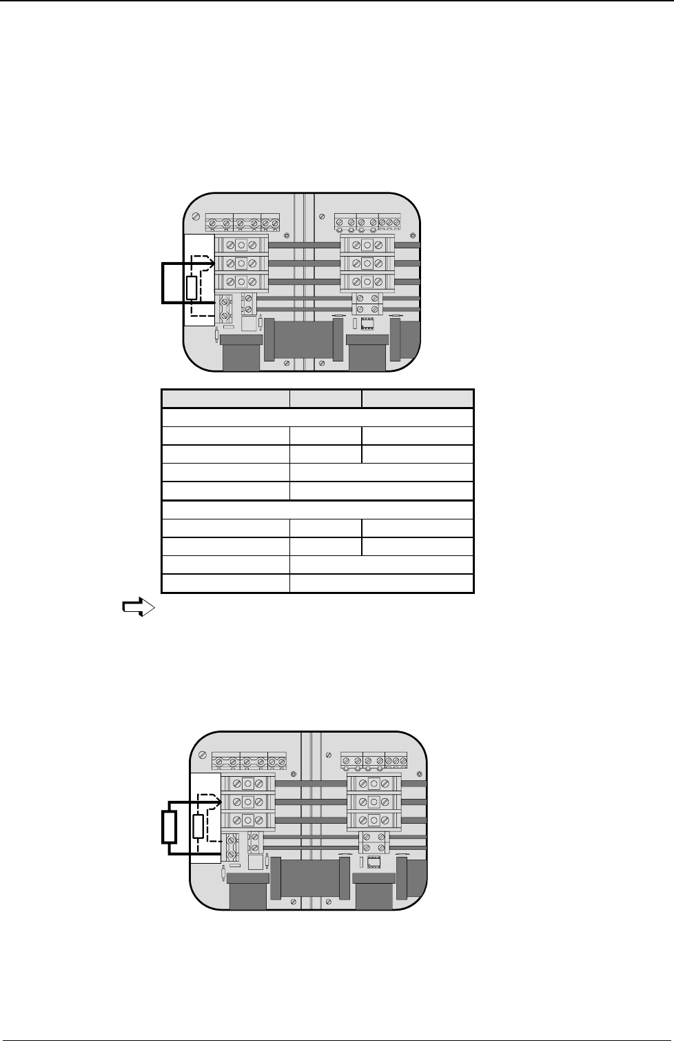
The internal ballast resistance is activated by a bridge between +LS and X5/1.
In the NMD20 delivery status this bridge is fitted.
L1 L2 L3 PE 24V
+-
X5
PE
+LS
-LS
UVWPEBrake
PE+ -
X1
X2
X5
X1
X2
X3
X4X4
1
2
X3
RBext
RBint
Braking power Duration Cooling down time
NMD10
17 kW <50 ms ≥ 10s
4.0 kW <1s ≥ 50s
Without fan: 120W unlimited
With fan: 250W unlimited
NMD20
9.5 kW <50 ms ≥ 10s
2.5 kW <1s ≥ 50s
Without fan: 120W unlimited
With fan: 200W unlimited
External ballast resistances can be used with NMD20 (see Page 193).
If the braking power of the internal ballast resistance is insufficient, an external
ballast resistance can be connected.
The external ballast resistance is connected between +LS and X5/2.
To do this, the bridge between +LS and X5/1 must be removed.
The full braking power cannot be used with this bridge present.
L1 L2 L3 PE 24V
+-
X5
PE
+LS
-LS
UVWPEBrake
PE+ -
X1
X2
X5
X1
X2
X3
X4X4
1
2
X3
RBext
RBint
RBext
Output X5 is protected from short circuits.
Thermal protection
An emergency stop is triggered at 85°C heat sink temperature, the ready contact is
released and the red LED lights up.
Activation of the
internal ballast
resistance for
NMD20
Maximum braking
power:
Connecting the
external ballast
resistance
Mains module NMD10/NMD20
Technical data / power features NMD
25
Unit
hardware
Connector
assignment / cable
Technical dataConfigurationPositioning and
control functions
Optimization
functions
InterfacesAccessories /
options
StatusParameterError list
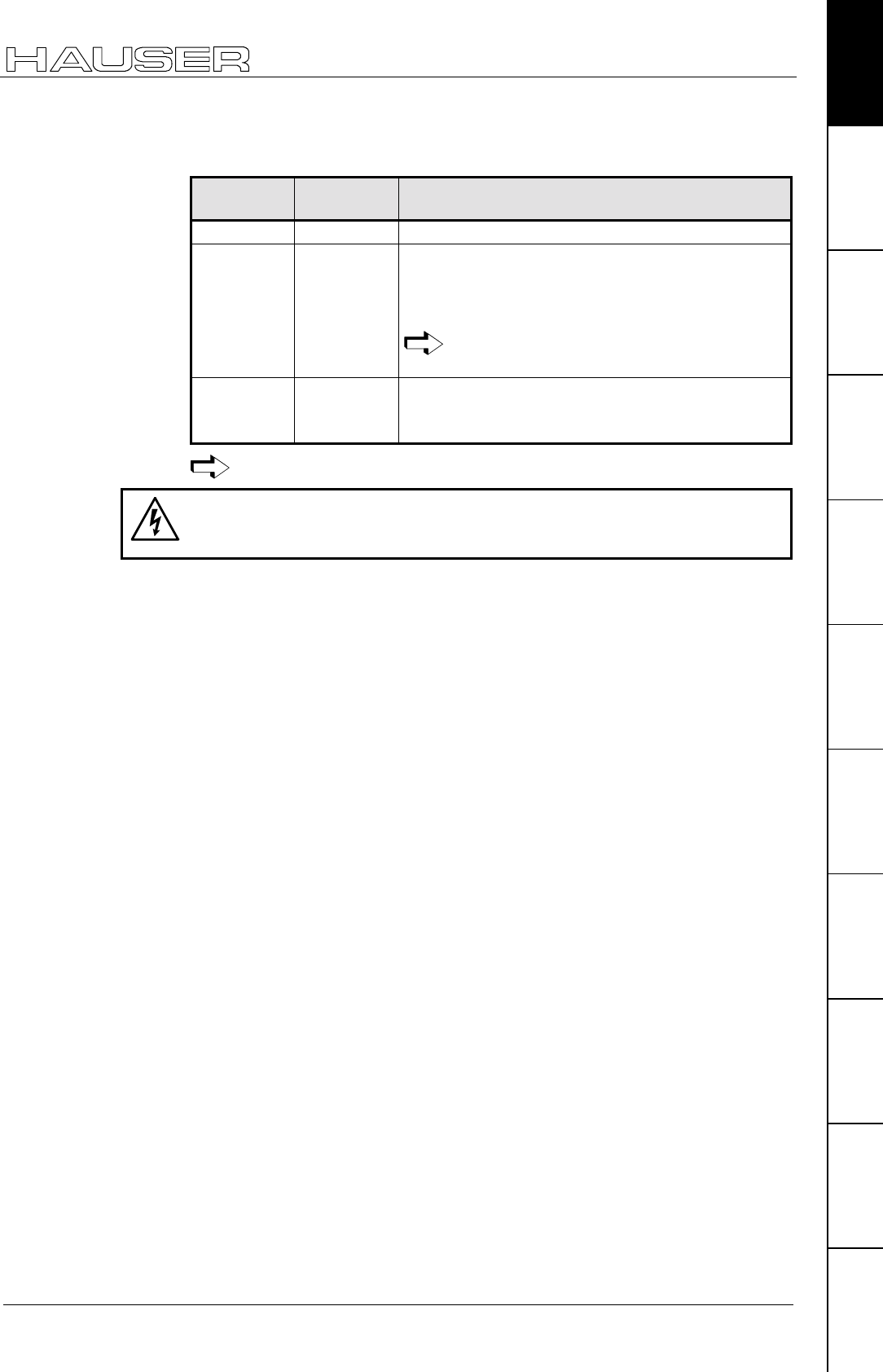
If a phase malfunctions, no displays appear
LED red
Error LED green
Ready Possible errors
off on no errors
on off ! Heat sink temperature too high
or
! error in logic voltage (24V DC too low or unit is
defective)
Emergency stop is activated and ready
contact is released.
on on ! Ballast switch overloaded
or
! undervoltage (<100V DC or <80V AC).
Ready contact and green LED are coupled.
Caution!
If the unit has no control voltage, no displays will indicate that operating voltage is
present.
Error diagnosis in
the mains module
Start-up manual COMPAX-M / -S
26
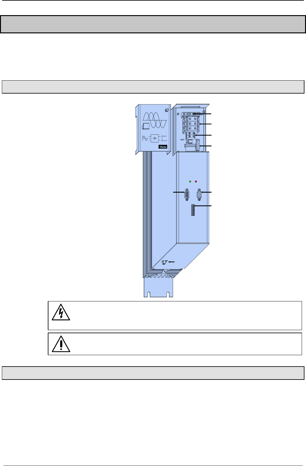
7.4 COMPAX 35XXS unit features
The 35 kW servo control COMPAX 35XXM - a performance upgrade to the
COMPAX family.
! Compact unit with output currents of 50 Aeff / 100 Aeff (<5s) with integrated power
unit.
! Additional COMPAX-M controllers of up to 15 KW can be arranged in rows.
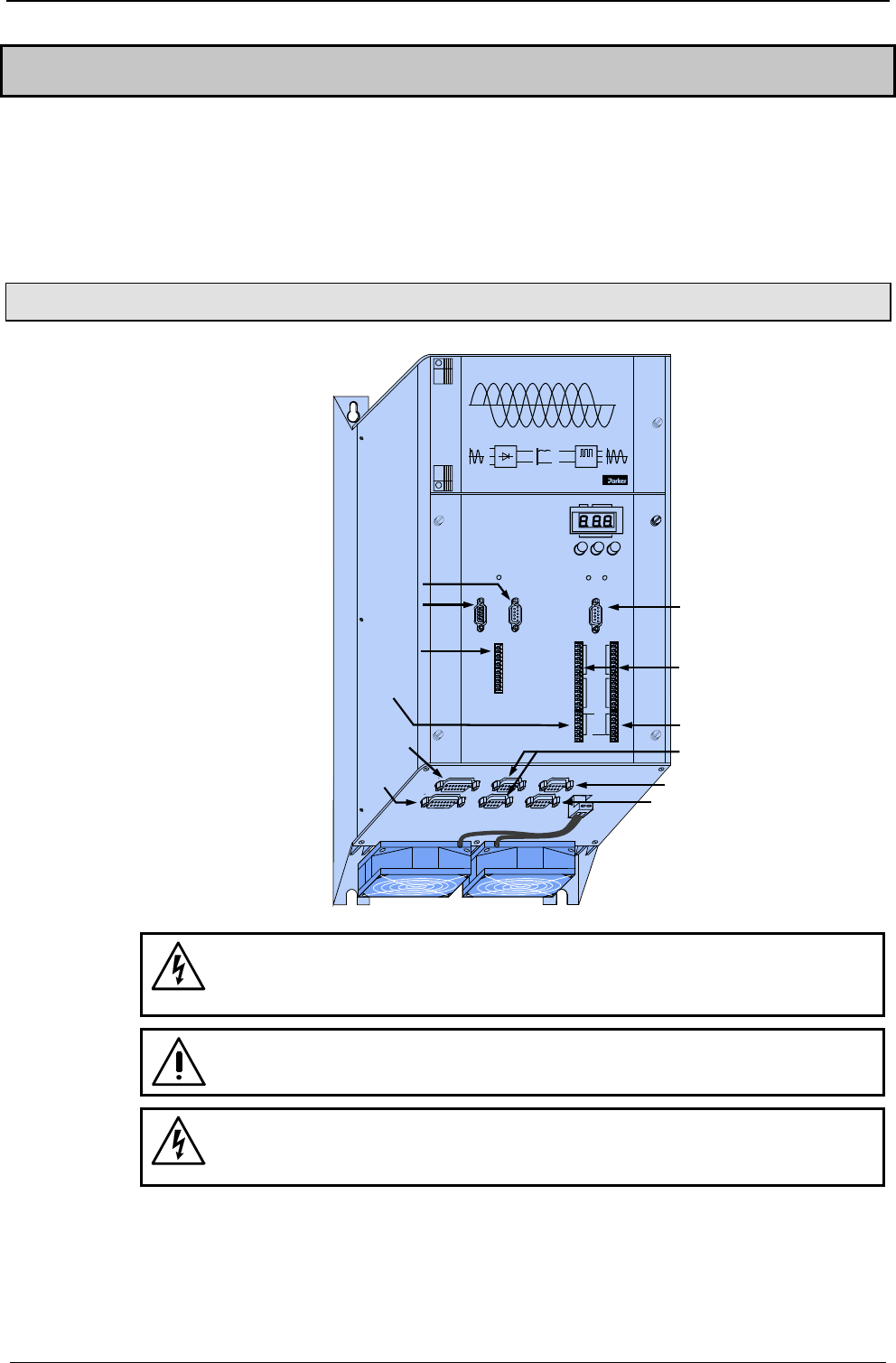
7.4.1 Plug and connection assignment COMPAX 35XXM
Digital
COMPAX-M
X5 X7
IN OUT
X19
Control
H1
X6
Input
Output
Status
Value
+- Enter
Ready Error
RS 232
Test
Control
X8 X10
X9 X11
Number
X13
Encoder
X9 Test
X6 RS232
X7 OUT
X5 IN
Bus
systems:
X19
Control X8/X10 In-/
Output
X11 Control
X14/X15
HEDA
X17 Initiators
X16 Absolute
encoder
X12
Resolver
Before wiring up, always de-energize the unit.
Even once the mains supply has been switched off, dangerous
levels of voltage can remain in the system for up to 5 min.
When working with motors without a holding brake, the brake lines
must not be connected to COMPAX
Caution!
If the unit has no control voltage, no displays will indicate that operating
voltage is present.
COMPAX 35XXS unit features
Installation and dimensions of COMPAX 35XXM
27
Unit
hardware
Connector
assignment / cable
Technical dataConfigurationPositioning and
control functions
Optimization
functions
InterfacesAccessories /
options
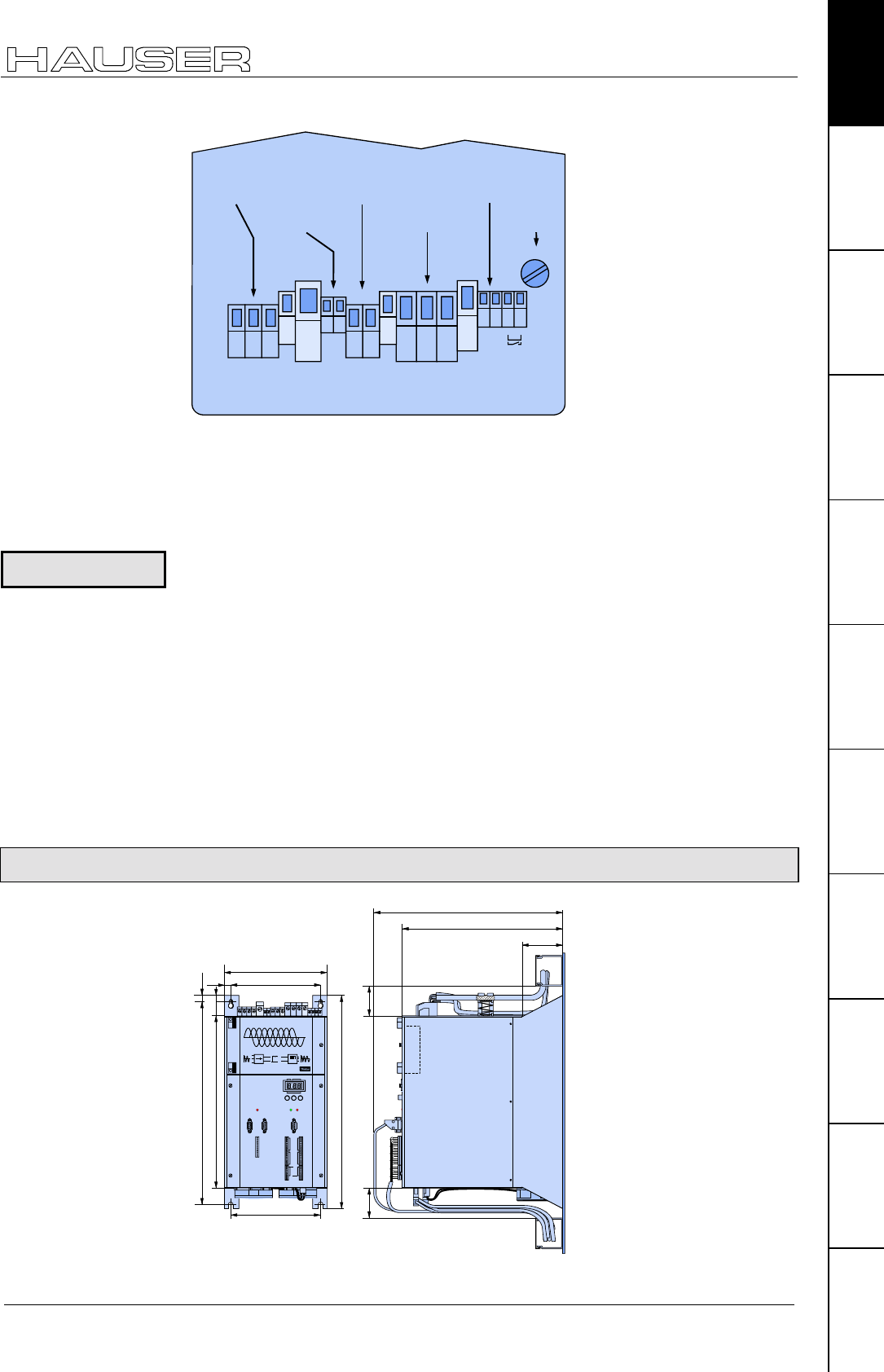
StatusParameterError list
L1 L2 L3
PE
PE
PE
+-
UVW
PE
+-
F1
Mains Input
DC - In Braking
Motor
Motor
X 20
24 V
X 21
Resistance
X 22 X 1
Brake
X 23
motor
AC - voltage
up to 500V AC
24V control
voltage
external
ballast
resistor motor
brake
F1
3.16A
Supply voltage up to max. 3 * 500V AC
Operating range: 3*80V AC - 3*500V AC; 45 - 65 Hz.
Typical AC mains: 400V ±10%; 460V ±10%;480V ±5%
! Layout of contactors for the power supply:
Capacity according to device performance: Application group AC3
Switching on the operating voltage for a second time:
Before switching on the operating voltage for a second time, you must wait for at
least 2.5 minutes otherwise you may overload the condenser load resistance.
Control voltage
! 21.6V to 26.4V DC • Ripple: < 1VSS • fuse protection: max. 16A
Mains supply fuse protection
62A K circuit breaker or suitable Neozed conventional fuse.
Regeneration mode
! Storable energy: 3450µF/542 Ws
! External ballast resistance: 10Ω/2 kW
For the external ballast resistors available, please see Page 193.
7.4.2 Installation and dimensions of COMPAX 35XXM
390
340
86
65 65
218
190
450
363
190
430 10
14
38
Digital
COMPAX-M
X5 X7
IN OUT
X19
Control
H1
X6
Input
Output
Status
Value
+-Enter
Ready Error
RS 232
Test
Control
X8 X10
X9 X11
Number
Fastening with 4 M6 hex-socket head screws.
Plan view
Specific technical
data
Note!
Start-up manual COMPAX-M / -S
28
7.4.3 Wiring COMPAX 35XXM
L1 L2 L3
PE
PE
PE
+-
UVW
PE
+-
F1
Mains Input
DC - In Braking
Motor
Motor
X 20
24 V
X 21
Resistance
X 22 X 1
Brake
X 23
UVW
+-
L1 L2 L3
PE PE
Motor
Supply up to
500V AC
24V Control voltage
External
braking resistance
Motor
brake*
F1
3.16A
Connection for
external contact
for brake control
black 5
black 4
black 3
black 2
black 1
green / yellow
123
45
68910
11121314
7
green / yellow
green / yellow
* max. 1.6A
The PE connection must be a version of at least 10mm2
COMPAX-M / SV-M
...
X5 X7
IN OUT
X19
Control
H1
HAUSER
COMPAX-M
DIGITAL
Status Number
X6
X8 X10
-+Enter
Ready Error
RS232
Input
Output
Test
Control
X9 X11
Value
Cable conduit
COMPAX 35XXM
...
Motor
UVWPEBrake
PE+ -
X5
X1
X2
X3
X4
24V+
-15
16
17
18
PE
LS+
LS-
Voltage supply 24V
Emergency stop,
stand by and
bus signals
Last device
equiped with
terminal plug
Wiring up motor,
mains power /
control voltage
and external
ballast resistance
Wiring up system
network
COMPAX 35XXS unit features
COMPAX 35XXM connector assignment
29
Unit
hardware
Connector
assignment / cable
Technical dataConfigurationPositioning and
control functions
Optimization
functions
InterfacesAccessories /
options
StatusParameterError list
7.4.4 COMPAX 35XXM connector assignment
X13/1 Housing
X13/2 N2
X13/3 B2
X13/4 A2
X13/5 N1
X13/6 B1
X13/7 A1
X13/8 +5V
X13/9 N2/
X13/10 B2/
X13/11 A2/
X13/12 N1/
X13/13 B1/
X13/14 A1/
X13/15 GND
X10/1 I9
X10/2 I10
X10/3 I11
X10/4 I12
X10/5 I13
X10/6 I14
X10/7 I15
X10/8 I16
X10/9 O9
X10/10 O10
X10/11 O11
X10/12 O12
X10/13 O13
X10/14 O14
X10/15 O15
X10/16 O16
X9/1 +24V
X9/2 GND
X9/3 reserved
X9/4 reserved
X9/5 24V
X9/6 15-24V Emerg. stop*
X9/7 Housing
X14(15)/1
NC
X16/1
T-
X17/6
GND
X17/7
Sig.MN
X17/8
Sig. E2
X17/9
Sig. E1
X14(15)/2
RxC
X14(15)/3
TxC
X14(15)/4
RxD
X14(15)/5
TxD
X14(15)/6
RxC/
X14(15)/7
TxC/
X14(15)/8
RxD/
X14(15)/9
TxD/
X16/2
NC
X16/3
D-
X16/4
NC
X16/5
GND
X16/6
T+
X16/7
NC
X16/8
D+
X16/9
+24V
X17: DA-monitor
initiators
X14/X15:
HEDA
X16:
Absolute
encoder
X13: Encoder
X9
X10:
Input / output
I9...I16; O9...O16
X8/1 I1
X8/2 I2
X8/3 I3
X8/4 I4
X8/5 I5
X8/6 I6
X8/7 I7
X8/8 I8
X8/9 O1
X8/10 O2
X8/11 O3
X8/12 O4
X8/13 O5
X8/14 O6
X8/15 O7
X8/16 O8
X17/1
DA-channel 0
X18/-
0V
X18/+
24V
X11/4
DA-channel 2
X11/3
Override
X11/2
GND
X11/1
+24V
X11/5
DA-channel 3
X11/6
Override (old)
X11/7
Shield
X17/2
DA-channel 1
X17/3
Shield
X17/4
GND 24V
X17/5
+24V
(Option D1) X11
X18:
Fan
X8:
Input / output
I1...I8; O1...O8
* can be parameterized
X1/2
V
PE
+LS
-LS
X21/1
+24 V
X21/2
0V
X6/2
RxD
X6/3
TxD
X6/4
DTR
X6/5
GND
X6/6
DSR
X6/7
RTS
X6/8
CTS
X6/9
+5V
X1/1
U
X1/3
W
PE
X23/3
Br'+
X23/4
Br+
X1:
Motor
HV dc and 24V
for additional
COMPAX-M
X21:
Control
voltage
X6:
RS232
X19/6
15-24V Emerg.stop
X19/7
24V
X19/8
reserved
X19/9
+24V
X19
X19/1
+24V
X19/2
GND
X19/3
Stand by P
X19/4
Stand by S
X19/5
+24V
X19/10
Enable
X19/11
Shield
X5: output bus systems
Assignment depends on
the bus system
X7: output bus systems
Assignment depends on
the bus system
X20/2
L2
X20/1
L1
X20/3
L3
PE
X20:
AC Supply
PE
X3/1
Braking
resistance X3/2
X22: Braking
resistance
X3/2
PE
X23/1
Br'+
X23/2
Br-
X23:
Motor brake
+24V
0V
X12/1 Housing
X12/2 +8V
X12/3 NC
X12/4 REF-
X12/5 SIN-
X12/6 NC
X12/7 GND
X12/8 ST+
X12/9 +5 V
X12/10 TEMP
X12/11 COS-
X12/12 COS+
X12/13 SIN+
X12/14 REF+
X12/15 ST-
X12: Resolver / SinCos
The assignment of X12 does not apply for the S3 option.
Enable final stage
Start-up manual COMPAX-M / -S
30
7.5 COMPAX 25XXS unit characteristics
7.5.1 COMPAX 25XXS connector and connection assignment
X6
Input
Out put
Status
Value
+
-
Ent er
Ready
Error
RS 232
Test
Control
X8
X10
X9
X11
Number
X6 RS232
X10 digital input
and output
X11 control
X8 input
/ output
X9 test
X12 resolver
X14 HEDA
X16 absolute
X18 fan
X13 encoder
X15 HEDA
X17 initiators
COMPAX-S
LED / color Meaning, when switched on
Ready / green 24V DC present and initialization complete
Error / red COMPAX - fault (E1...E56) present.
X5 Bus
systems IN
X7
X2
X3
X1
X4
F19
3.16 AT
PE
L3
L2
L1
PE
N
L
3 x 230V AC
1 x 230V AC
AC
supply
+
-24V DC
supply
Bus systems
OUT
motor and
motor brake
-
+
PE
W
V
U
PE
B
B-
+
braking
resistance
1
2
3
4
1
2
1
2
3
4
5
6
7
8
1
2
3
X2/
X3/
X1/
X4/
230V AC
230V AC
230V AC
L1
L2 L3
max. 230V AC +10%
line to line voltage
!
Meaning of the
LEDs on the front
plate
Plan view of
COMPAX 25XXS
COMPAX 25XXS unit characteristics
COMPAX 25XXS connector and connection assignment
31
Unit
hardware
Connector
assignment / cable
Technical dataConfigurationPositioning and
control functions
Optimization
functions
InterfacesAccessories /
options
StatusParameterError list
Before wiring up, always de-energize the unit.
Even once the mains supply has been switched off, dangerous
levels of voltage can remain in the system for up to 5 min.
When working with motors without a holding brake, the brake lines
must not be connected to COMPAX
The PE connection occurs with 10mm2 under a fixing bolt
Caution!
If the unit has no control voltage, no displays will indicate that operating
voltage is present.
On unit side
X5 RS485 IN
X7
X2
X3
X1
X4
F19 3.16 AT
PE
L3
L2
L1
PE
N
L
3 x 230V AC
1 x 230V AC
AC
supply
+
-
24V DC
supply
RS485
OUT
motor and
motor brake
-
+
PE
W
V
U
PE
B
B-
+
braking
resistance
connection for
external contact
for brake control
brake
+
-
PE
W
V
U
black 5
black 4
green/yellow
black 3
black 2
black 1
X1
sheetshielding of motor cable
230V AC
230V AC
230V AC
L1
L2 L3
max. 230V AC +10%
line to line voltage
!
! Note the screened connection of the motor cable on the upper side of the unit.
! Clamp the motor cable with the open section of the screen braid under the
ground terminal.
Motor side
! Via connectors.
The mains supply and control voltage supply are located on the upper side of the
unit.
Power supply: there are 2 options (with the same output power):
3 * 80V AC - 3 * 250V AC •
••
• 45-65Hz •
••
• fuse protection: 10A
1 * 100V AC - 1 * 250V AC •
••
• 45-65Hz •
••
• Fuse protection: 16A
! Layout of contactors for the power supply:
Capacity according to device performanc: Application group AC3.
Wiring up motor
Wiring up mains
power / control
voltage
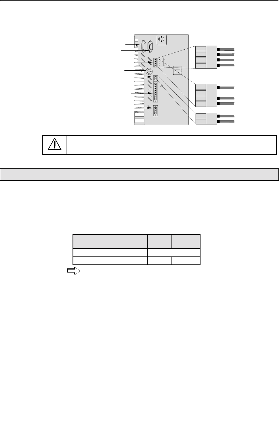
Start-up manual COMPAX-M / -S
32
! Control voltage 24V DC ±10% ripple <1VSS
Fuse protection: 16A
X4
PE
L3
L2
L1
PE
N
L
3 x 230V AC
1 x 230V AC
+
-
-
+
PE
W
V
U
PE
B
B-
+
brake
resistance
1234
PE
L3
L2
L1
1234
PE
L
N
12
-
+
Connections for
3 x 230V AC
Connections for
1 x 230V AC
Bus system
X5 IN
X2
X3
X1
F19 3.16 AT
AC
supply
24V DC
supply
Bus system
X7 OUT
motor and
motor brake
24V control voltage
230V AC
230V AC
230V AC
L1
L2 L3
max. 230V AC +10%
line to line voltage
!
Note! Do not apply 3 * 400V AC.
Only wire up brake in motors with a holding brake! Otherwise, do not
wire up.
7.5.2 COMPAX 25XXS-specific technical data
! Energy recuperated during braking is stored in the supply capacitors. The
capacity and storable energy is:
COMPAX 25XXS: 1000 µ
µ µ
µF / 27 Ws
If the recuperated energy causes overvoltage, then external ballast resistances can
be engaged.
Braking power Duration Cooling
down time
COMPAX 25XXS: ≤1.0 kW unlimited
with Rext ≥ 56Ω: ≤2.5 kW <2s ≥ 10s
We can supply external ballast resistances for COMPAX 25XXS
(see Page 193).
Connecting ballast resistance to COMPAX-S
The ballast resistance is connected to B+, B- and, if necessary, PE.
Output X4 is protected from short circuits.
Mating connectors for X1,..X4 from Phoenix are included with the following type
designations:
X1: MSTB2.5/8/STF-5.08 (with screw connection)
X2: MSTB2.5/4/ST-5.08 (without screw connection)
X3: MSTB2.5/2/ST-5.08 (without screw connection)
X4: MSTB2.5/3/STF-5.08 (with screw connection)
You can acquire Phoenix housings for these connectors and these can be used
once adapted to our cables. Designation: KGG-MSTB2.5/(pin number).
Overvoltage
limitation
Maximum braking
power with
external ballast
resistance
Mating
connectors X1,
X2, X3 and X4
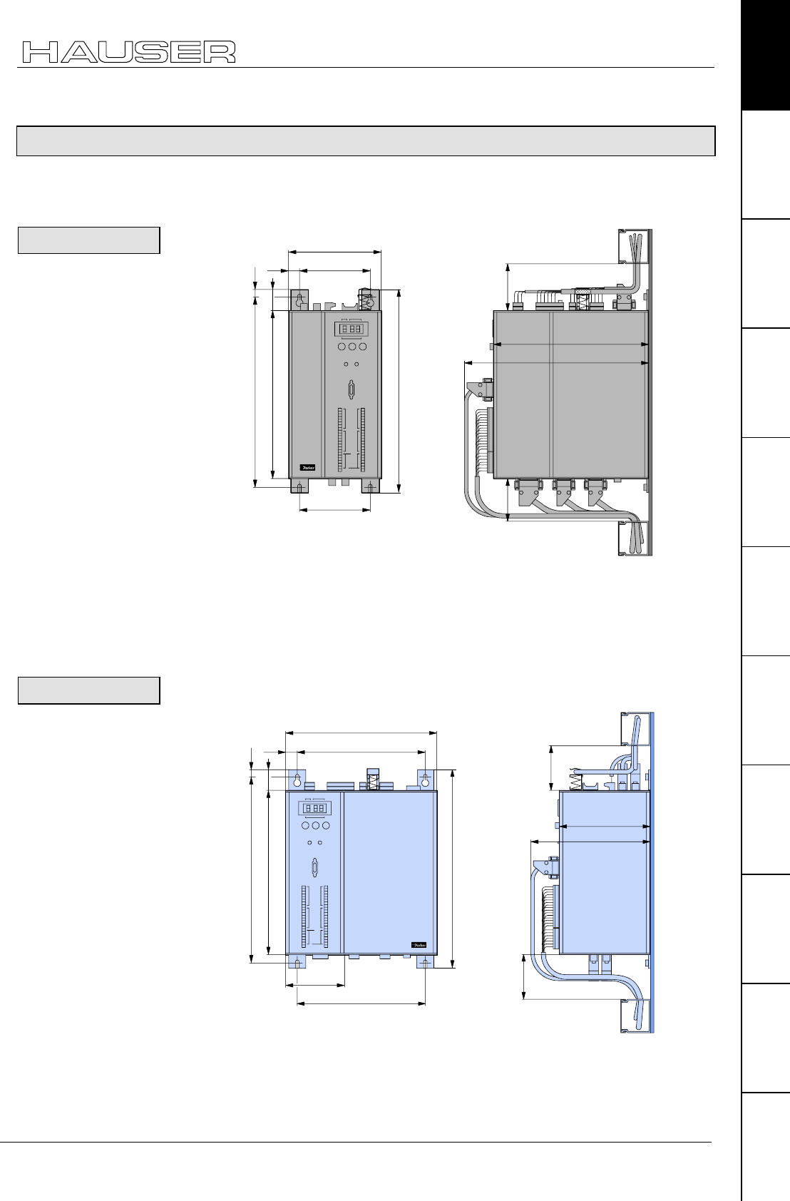
COMPAX 25XXS unit characteristics
COMPAX 25XXS dimensions / installation
33
Unit
hardware
Connector
assignment / cable
Technical dataConfigurationPositioning and
control functions
Optimization
functions
InterfacesAccessories /
options
StatusParameterError list
7.5.3 COMPAX 25XXS dimensions / installation
The two retaining plates supplied can be attached to the back/left side or the heat
sink side. Retaining screws: 4 M6 hex-socket head screws.
290
Status Number
X6
X8 X10
-+Enter
Ready Error
RS232
Input
Output
Test
Control
X9 X11
Value
98
130
270
240
10
30
16
65
65
221
271
98
COMPAX-S
The left-hand side of the unit heat sink is fastened to a metal wall using 2 retaining
plates.
Installation distance: 135mm (device distance:5mm)
Delivery status
The design is delivered ready for connection in series!
The left-hand side of the unit heat sink is fastened to a metal wall using 2 retaining
plates.
Status Number
X6
X8 X10
-+Enter
Ready E rror
RS232
Inp ut
Output
Test
Control
X9 X11
Value
186
270
240
290
10
30
186
220
65
65
131
181
17
95
COMPAX-S
! Install the retaining plate on the required side.
! Unfasten front plate and blind plate. There are 2 screws on both the upper and
lower sides of the unit.
Install the front plate and then the blind plate at the required point.
Design in series
Flat design
Converting the
front plates
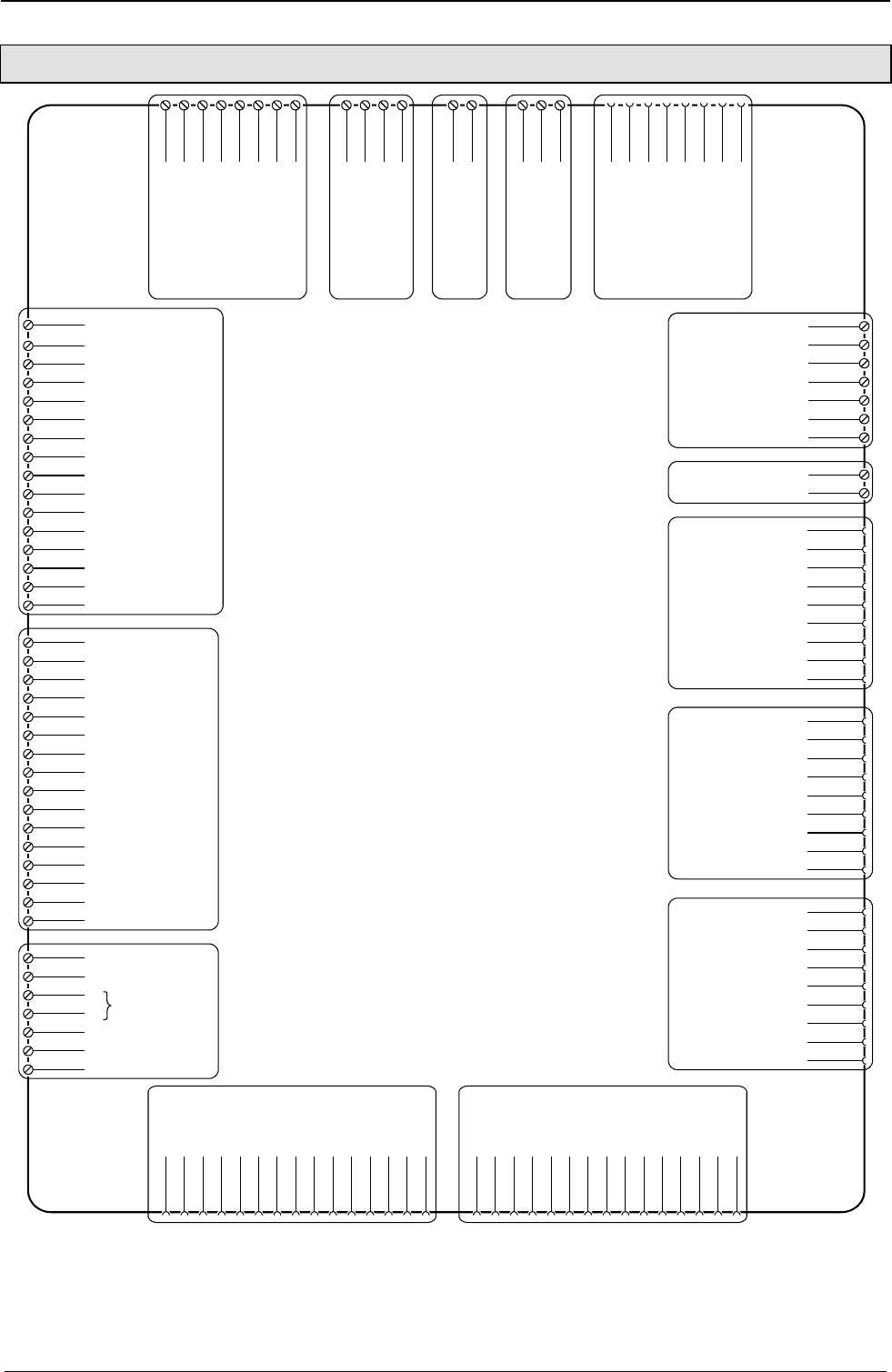
Start-up manual COMPAX-M / -S
34
7.5.4 Connector assignment COMPAX 25XXS
X12/1 housing
X12/2 +8V
X12/3 NC
X12/4 REF-
X12/5 SIN-
X12/6 NC
X12/7 GND
X12/8 ST+
X12/9 +5 V
X12/10 TEMP
X12/11 COS-
X12/12 COS+
X12/13 SIN+
X12/14 REF+
X12/15 ST-
X13/1 housing
X13/2 N2
X13/3 B2
X13/4 A2
X13/5 N1
X13/6 B1
X13/7 A1
X13/8 +5V
X13/9 N2/
X13/10 B2/
X13/11 A2/
X13/12 N1/
X13/13 B1/
X13/14 A1/
X13/15 GND
X1/2
V
X2/1
L1
X2/2
L2
X2/3
L3
X2/4
PE
X3/1
+24 V
X3/2
0V
X4/1
B+
X4/2
B-
X4/3
PE
X8/1 I1
X8/2 I2
X8/3 I3
X8/4 I4
X8/5 I5
X8/6 I6
X8/7 I7
X8/8 E8
X8/9 O1
X8/10 O2
X8/11 O3
X8/12 O4
X8/13 O5
X8/14 O6
X8/15 O7
X8/16 O8
X10/1 I9
X10/2 I10
X10/3 I11
X10/4 I12
X10/5 I13
X10/6 I14
X10/7 I15
X10/8 I16
X10/9 O9
X10/10 O10
X10/11 O11
X10/12 O12
X10/13 O13
X10/14 O14
X10/15 O15
X10/16 O16
X9/1 +24V
X9/2 GND
X9/3 P
X9/4 S
X9/5 24V
X9/6 15V - 24V emerg. stop
X9/7 housing
X14(15)/1
NC
X17/1
DA-channel 0
X18/-
0V
X18/+
24V
X11/4
DA-channel 2
X11/3
Override
X11/2
GND
X11/1
+24V
X16/1
T-
X6/2
RxD
X6/3
TxD
X6/4
DTR
X6/5
GND
X6/6
DSR
X6/7
RTS
X6/8
CTS
X6/9
+5V
L
N
PE
X11/5
DA-channel 3
X11/6
Override (old)
X11/7
shield
X17/2
DA-channel 1
X17/3
shield
X17/4
GND 24V
X17/5
+24V
X17/6
GND
X17/7
Sig.MN
X17/8
Sig. E2
X17/9
Sig. E1
X14(15)/2
RxC
X14(15)/3
TxC
X14(15)/4
RxD
X14(15)/5
TxD
X14(15)/6
RxC/
X14(15)/7
TxC/
X14(15)/8
RxD/
X14(15)/9
TxD/
X16/2
NC
X16/3
D-
X16/4
NC
X16/5
GND
X16/6
T+
X16/7
NC
X16/8
D+
X16/9
+24V
(Option D1)
Stand by
X1/1
U
X1/3
W
X1/4
PE
X1/5
Br`+
X1/6
Br-
X1/7
Br`+
X1/8
Br+
X1:
motor
brake
X2:
AC supply X3:
control
voltage
X4:
braking
resistance
X6:
RS232
X11
X18: fan
X17:
DA-monitor
initiators
X14/X15:
HEDA
X16:
absolute
encoder
X13: encoderX12: resolver / SinCos
X9
X10:
input /
output
I9...I16
O9...O16
X8:
input /
output
I1...I8
O1...O8
The assignment of X12 does not apply for the S3 option.
You will find the assignment of the connectors X5 and X7 (bus systems)
on Page 63!
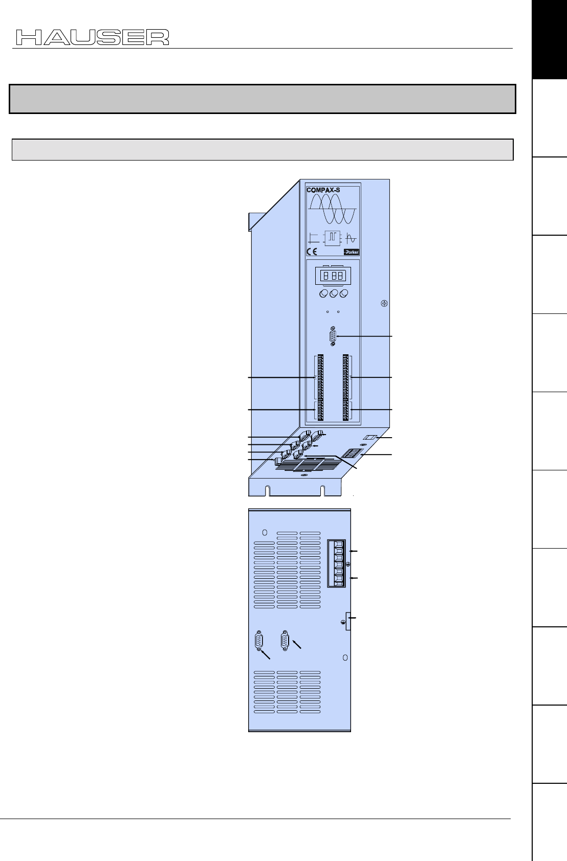
COMPAX 45XXS/85XXS unit characteristics
Plug and connection assignment COMPAX 45XXS/85XXS
35
Unit
hardware
Connector
assignment / cable
Technical dataConfigurationPositioning and
control functions
Optimization
functions
InterfacesAccessories /
options
StatusParameterError list
7.6 COMPAX 45XXS/85XXS unit characteristics
7.6.1 Plug and connection assignment COMPAX 45XXS/85XXS
X11X9
Input
Output Output
Input
Test Control
X10
X6
X8
RS232
Ready Error
ENTER+-
Value
Status Number
X9 test
X12 resolver
X16 absolute
X14 HEDA
X18 reserved
X11 Control
X6 RS232
output
motor
X17 initiators
X13 encoder
DIGI TAL
X15 HEDA
X8 digital input
/ output X10 digital input
/ output
ext. supply
HV
TD
L1
L2
L3
AC
supply
Ballast
resistor
X5 RS485 IN
X7 RS485 OUT
RD
X2
Connection
PE 10mm2
Plan view
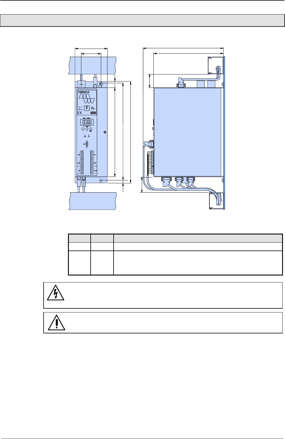
Start-up manual COMPAX-M / -S
36
7.6.2 COMPAX 45XXS/85XXS installation / dimensions
395
DIGI TAL
24
378
351
77
125
65
275
325
11
65
Fastening: 4 M5 hex-socket head screws
Installation distance: 130mm (device distance:5mm)
LED Color Meaning, when switched on
Ready Green 24V DC present and initialization complete
Error red CPX error present.
or
mains supply or control voltage absent.
Before wiring up, always de-energize the unit.
Even once the mains supply has been switched off, dangerous
levels of voltage can remain in the system for up to 5 min.
When working with motors without a holding brake, the brake lines
must not be connected to COMPAX
Meaning of the
LEDs on the front
plate
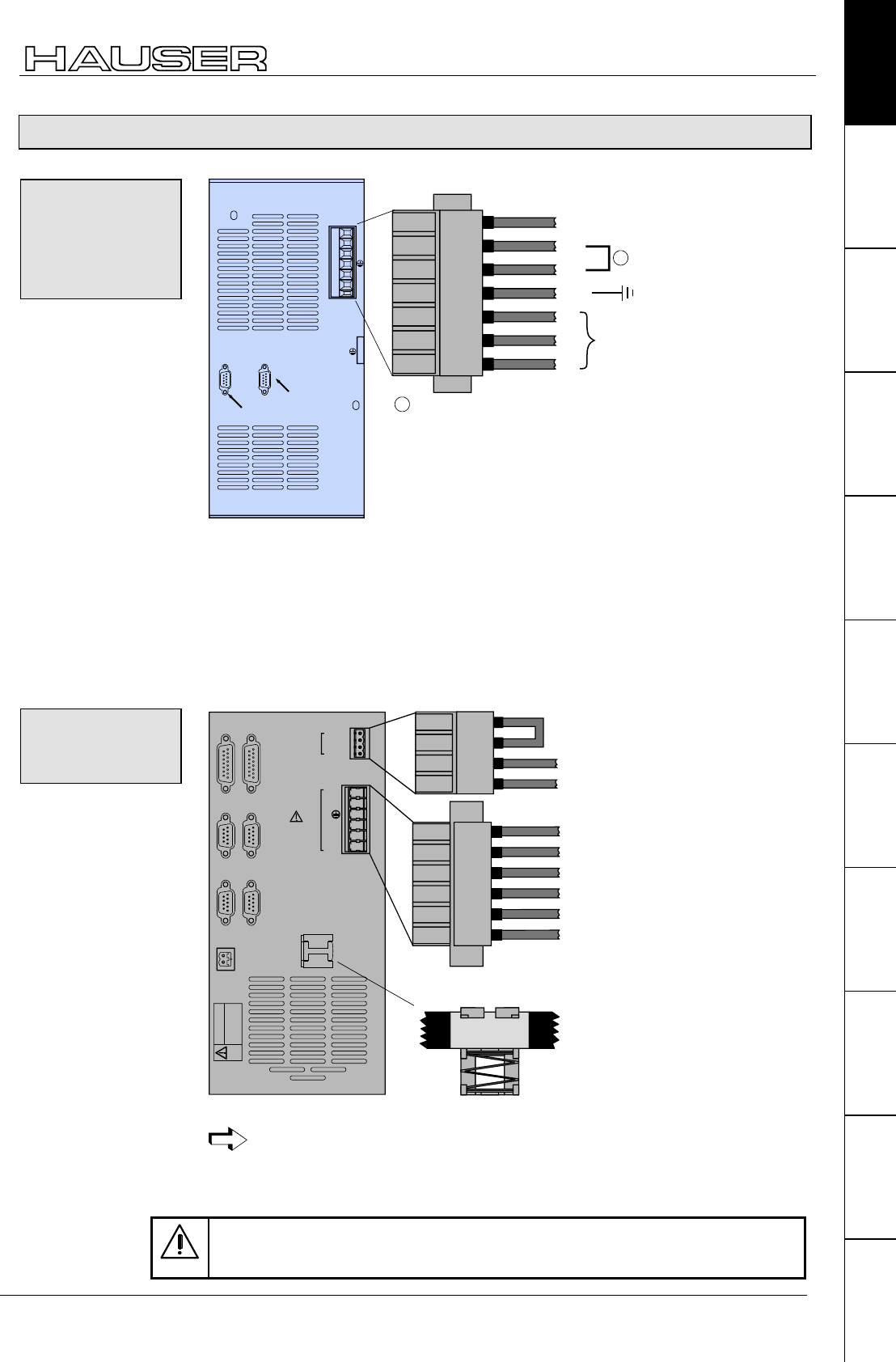
COMPAX 45XXS/85XXS unit characteristics
COMPAX 45XXS/85XXS-specific wiring
37
Unit
hardware
Connector
assignment / cable
Technical dataConfigurationPositioning and
control functions
Optimization
functions
InterfacesAccessories /
options
StatusParameterError list
7.6.3 COMPAX 45XXS/85XXS-specific wiring
PE
L1
L2
L3 400V -
line
1234 756
RD
HV:
1
TD
High vol-
tage DC
1Enable internal ballast resistor
X2
HV
TD
L1
L2
L3
X5 IN
X7 OUT
RD
X2
Bus system
X2HV: DC current output
! Power supply: 3 * 80V AC - max. 3 * 500V AC
Fuse protection: max. 16A
! Layout of contactors for the power supply
♦
Capacity according to device performance: Application group AC3
Control voltage: 24V DC ±10% ripple <1VSS -
BR1
W
V
U
ISOL 0V
Motor
Outputs
Enable -
Enable +
24V Input
24V GND
123456
Brake
+
-
PE
W
V
U
black 5
black 4
green/yellow
black 3
black 2
black 1
X1
Sheetshielding of
motor cable
Enable
Enable
+24V DC
0V
1234
X3
WARNING
Risk of electric shock
If case is not erthed
Connenct earth
before connecting supply
X1
Note the screened connection of the motor cable on the lower side of the unit.
Clamp the motor cable with the open section of the braided screen under the
ground terminal.
Only wire up brake lines in motors which have a holding brake.
Otherwise, do not wire up.
Wiring up mains
power /
enabling
internal ballast
resistance
Wiring up motor
/ control voltage
/ enable
Start-up manual COMPAX-M / -S
38
The final stage is enabled using a bridge between X3/1 - X3/1.
If this connection is missing, the final stage is voltage-free and error message E40
appears (see from Page 223).
! Energy recuperated during braking is stored in the supply capacitors. The
capacity and storable energy is:
COMPAX 45XXS: 330µF/52 Ws
COMPAX 85XXS: 500µF/80 Ws
If the recuperated energy causes overvoltage, then the internal ballast resistance is
engaged.
Enable internal ballast resistance: X2/5 - X2/6
The internal ballast resistance is enabled by a bridge between X2/5 and X2/6.
If this connection is missing, the controller operates without ballast resistance; in
braking mode, error message E38 may appear (see from Page 223).
Braking power Duration Cooling
down time
COMPAX 45/85S: 300W unlimited
≤1.5 kW <10s ≥ 10s
We provide external ballast resistances for COMPAX 45XXS / 85XXS (see
Page 193).
Connecting a ballast resistance to COMPAX 4500S/ COMPAX 8500S
The ballast resistance is connected to HV, TD and PE.
The output is protected from short circuits.
Note!
When an external ballast resistance is connected, the bridge between RD and TD
must be removed.
Enable bridges:
X3/1 - X3/2
Overvoltage
limitation
Maximum braking
power of the
internal ballast
resistance
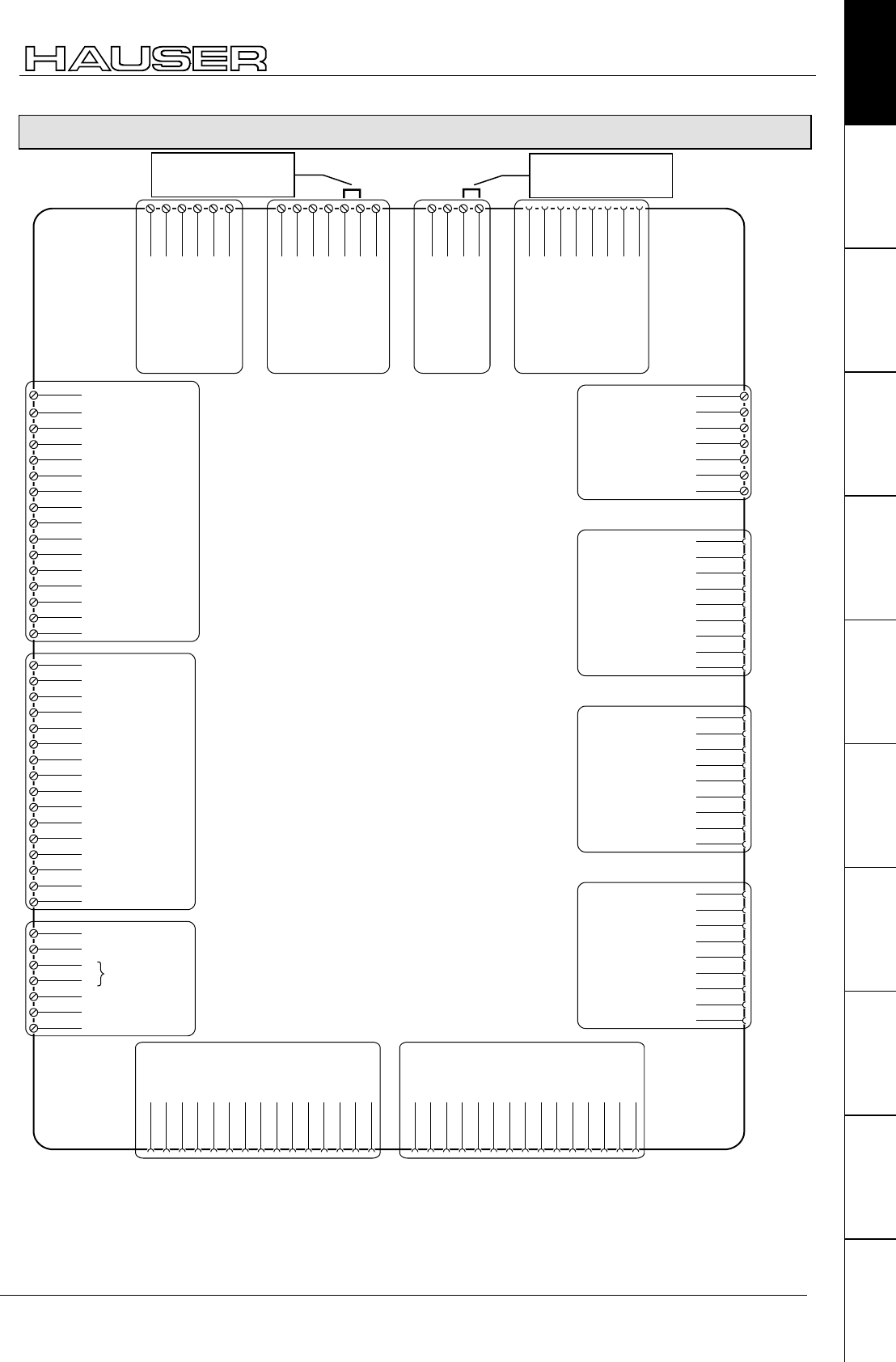
COMPAX 45XXS/85XXS unit characteristics
COMPAX 45XXS/85XXS connector and pin assignment
39
Unit
hardware
Connector
assignment / cable
Technical dataConfigurationPositioning and
control functions
Optimization
functions
InterfacesAccessories /
options
StatusParameterError list
7.6.4 COMPAX 45XXS/85XXS connector and pin assignment
X12/1 housing
X12/2 +8V
X12/3 NC
X12/4 REF-
X12/5 SIN-
X12/6 NC
X12/7 GND
X12/8 ST+
X12/9 +5 V
X12/10 TEMP
X12/11 COS-
X12/12 COS+
X12/13 SIN+
X12/14 REF+
X12/15 ST-
X13/1 housing
X13/2 N2
X13/3 B2
X13/4 A2
X13/5 N1
X13/6 B1
X13/7 A1
X13/8 +5V
X13/9 N2/
X13/10 B2/
X13/11 A2/
X13/12 N1/
X13/13 B1/
X13/14 A1/
X13/15 GND
X8/1 I1
X8/2 I2
X8/3 I3
X8/4 I4
X8/5 I5
X8/6 I6
X8/7 I7
X8/8 I8
X8/9 O1
X8/10 O2
X8/11 O3
X8/12 O4
X8/13 O5
X8/14 O6
X8/15 O7
X8/16 O8
X10/1 I9
X10/2 I10
X10/3 I11
X10/4 I12
X10/5 I13
X10/6 I14
X10/7 I15
X10/8 I16
X10/9 O9
X10/10 O10
X10/11 O11
X10/12 O12
X10/13 O13
X10/14 O14
X10/15 O15
X10/16 O16
X9/1 +24V
X9/2 GND
X9/3 P
X9/4 S
X9/5 24V
X9/6 15V - 24V emergency
stop
X9/7 housing
stand by
X1/2
V
X1/1
U
X1/3
W
X1/4
PE
X1/5
brake +
X1/6
brake -
X1:
motor
brake
X6/2
RxD
X6/3
TxD
X6/4
DTR
X6/5
GND
X6/6
DSR
X6/7
RTS
X6/8
CTS
X6/9
+5V
X6:
RS232
X11/4
DA-channel 2
X11/3
Override
X11/2
GND
X11/1
+24V
X11/5
DA-channal 3
X11/6
Override (old)
X11/7
shield
X11
X17/1
DA-channel 0
X17/2
DA-channel 1
X17/3
shield
X17/4
GND 24V
X17/5
+24V
X17/6
GND
X17/7
Sig.MN
X17/8
Sig. E2
X17/9
Sig. E1
(Option D1)
X17:
DA-monitor
Initiators
X14(15)/1
NC
X14(15)/2
RxC
X14(15)/3
TxC
X14(15)/4
RxD
X14(15)/5
TxD
X14(15)/6
RxC/
X14(15)/7
TxC/
X14(15)/8
RxD/
X14(15)/9
TxD/
X14/X15:
HEDA
X16/1
T-
X16/2
NC
X16/3
D-
X16/4
NC
X16/5
GND
X16/6
T+
X16/7
NC
X16/8
D+
X16/9
+24V
X16:
absolute-
encoder
X13: encoder
X12: resolver / SinCos
X9
X10:
Input /
Output
I9...I16
O9...O16
X8:
Input /
Output
I1...I8
O1...O8
X2/1
L1
X2/2
L2
X2/3
L3
X2/4
PE
X2:
AC supply
X2/5
RDX2/6
X2/7
+direct current
voltage
TD
X3/4
0 V
X3/3
+24V
X3:
control
voltage
X3/2
Enable power
output stage X3/1
The assignment of X12 does not apply for the S3 option.
You will find the assignment of the connectors X5 and X7 (bus systems)
on Page 63!
Releasing internal
ballast resistance
Releasing final stage
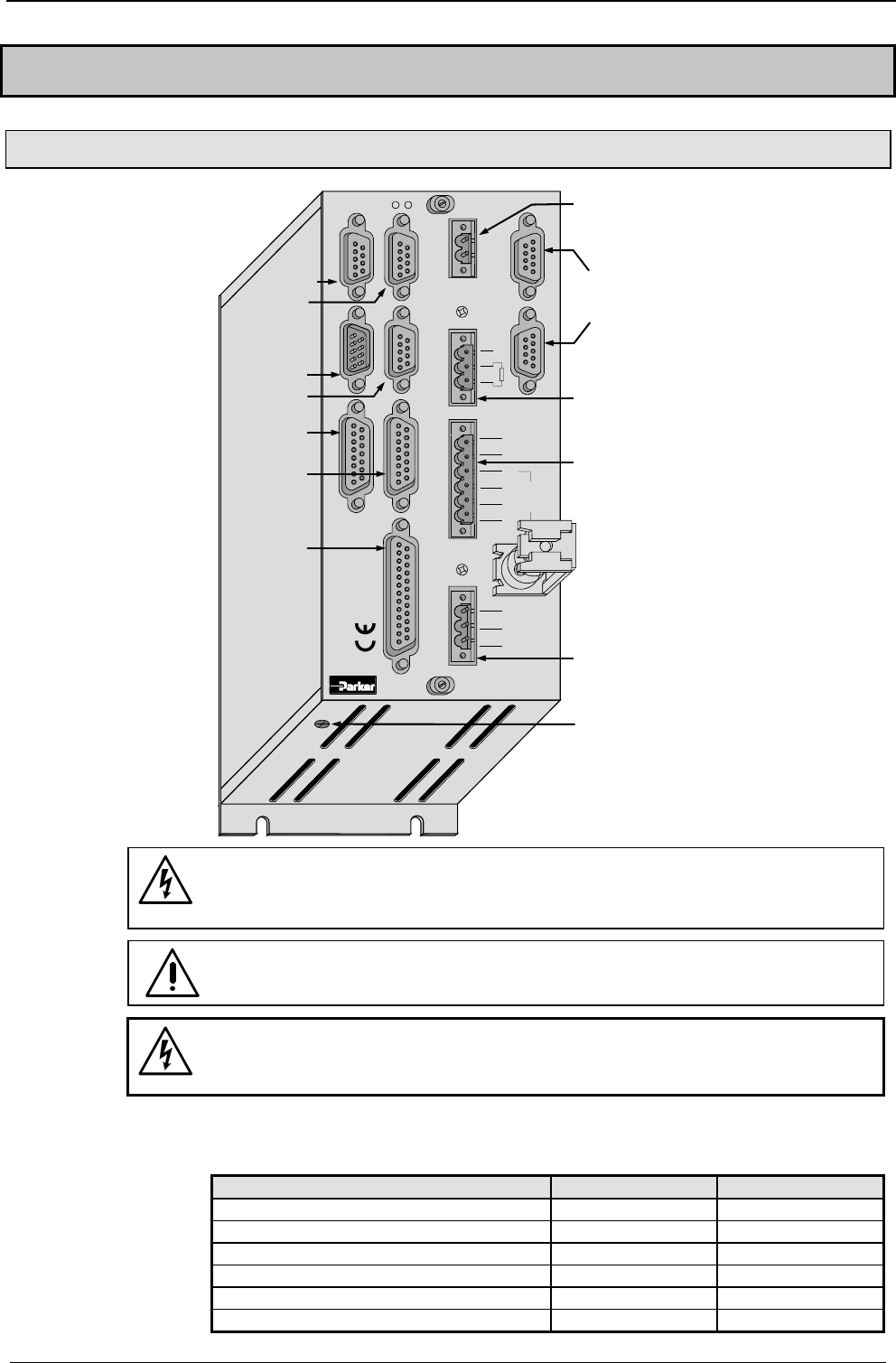
Start-up manual COMPAX-M / S
40
7.7 COMPAX 1000SL Unit characteristics
7.7.1 Connector and terminal assignment for COMPAX 1000SL
Fieldbus In
Encoder
Input / Output Resolver Fieldbus Out Limit Switch
24 V DC
RDump
H2
H1
RS232 X6X5X13
X12 X17
X19
X2 X1 X4 X3
X14 X15
HEDA Out HEDA In
Input
+-
L1 N PE UVWPE + -
Motor Brake
PE
+-
230 V AC
COMPAX - SL
X7
X13
encoder
X6 RS232
X7 OUT
X5 IN
bus
systems:
X19 in-/
output
X14/X15
HEDA
X17
initiators
X12
resolver
X3 24V DC
supply
X4 ballast
resistance
X1 motor /
motor brake
X2 230V AC
supply
PE -
connection
Before wiring up, always de-energize the unit.
Even once the mains supply has been switched off, dangerous
levels of voltage can remain in the system for up to 5 min.
When working with motors without a holding brake, the brake lines
must not be connected to COMPAX
Caution!
If the unit has no control voltage, displays will not indicate if operating
voltage is present.
at least 2.5mm2
The following statuses are shown by the LEDs.
Status Red LED (H2) Green LED (H1)
24V not available off off
24V are switched on, boot up on off
Unit OFF off blinking
Unit error; drive switched off on blinking
Unit error; drive powered on on
Unit RUNNING off on
PE – terminal:
LED display
(Option)
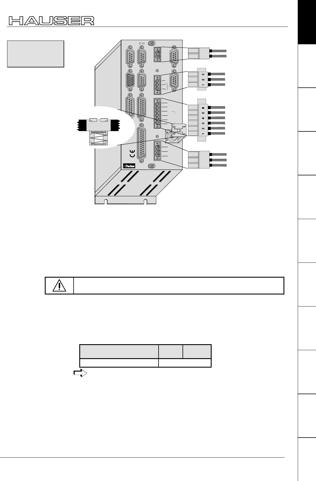
COMPAX 1000SL Unit characteristics
Connector and terminal assignment for COMPAX 1000SL
41
Unit
hardware
Connector
assignment / cable
Technical dataConfigurationPositioning and
control functions
Optimization
functions
InterfacesAccessories /
options
StatusParameterError list
Fieldbus InEncoder
Input / Output Resolver Fieldbus Out Limit Switch
24 V DC
RDump
H2
H1
RS232 X6X5X13
X12 X17
X19
X2 X1 X4 X3
X14 X15
HEDA Out HEDA In
Input
+-
L1 N PE UVWPE + -
Motor Brake
PE
+-
230 V AC
COMPAX - SL
X7
123
PE
L
N
X2 230V AC supply
12
-
+
24V control voltage
brake
+
-
PE
W
V
U
black 5
black 4
green / yellow
black 3
black 2
black 1
X1 motor / motor brake
PE
-
+
green / yellow
X4 ballast resistance
sheetshielding of motor cable
! Clamp the motor cable with the open section of the screen braid under the
ground terminal.
! Power supply:
1*100V AC - 1*250V AC • 45-65Hz • Fuse protection: 10A
! Layout of contactors for the power supply
Capacity according to device performance: Application group AC3
! Control voltage 24V DC ±10% ripple <1VSS • Fuse protection: max. 16A
The screen clamp for the screen connection of the motor cable is included and
must be screwed on in the illustrated position.
Only wire up brake in motors with a holding brake! Otherwise, do not
wire up.
! Energy recuperated during braking is stored in the supply capacitors. The
capacity and storable energy is:
COMPAX 10XXSL: 660 µ
µ µ
µF / 17 Ws
If the recuperated energy causes overvoltage, then external ballast resistances can
be engaged.
Braking power Duration Cooling
down time
COMPAX 10XXSL: ≤ 1.6kW unlimited
We provide external ballast resistances for COMPAX 1000SL
(see Page 193).
The ballast resistance is connected to B+, B- and, if necessary, PE.
Output X4 is protected against short circuiting.
Unit wiring
COMPAX
1000SL
Overvoltage
limitation
Maximum braking
power with external
ballast resistance
Connecting the
ballast resistance
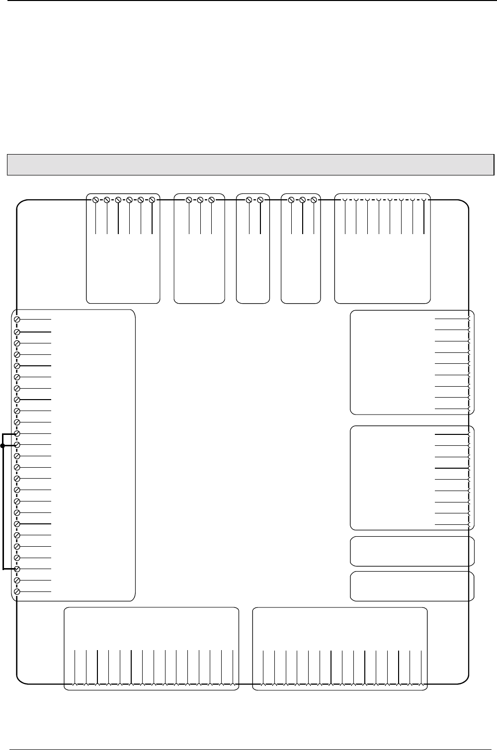
Start-up manual COMPAX-M / S
42
Mating connectors for X1,..X4 from Phoenix are included with the following type
designations:
X1: MSTB2.5/6/STF-5.08 (with screw connection)
X2: MSTB2.5/3/ST-5.08 (without screw connection)
X3: MSTB2.5/2/ST-5.08 (without screw connection)
X4: MSTB2.5/3/STF-5.08 (with screw connection)
You can acquire Phoenix housings for these connectors and these can be used
once adapted to our cables. Designation: KGG-MSTB2.5/(pin number).
7.7.2 Connector assignment COMPAX 1000SL (overview)
X12/1 housing
X12/2 +8V
X12/3 NC
X12/4 REF-
X12/5 SIN-
X12/6 NC
X12/7 GND
X12/8 ST+
X12/9 +5 V
X12/10 TEMP
X12/11 COS-
X12/12 COS+
X12/13 SIN+
X12/14 REF+
X12/15 ST-
X12: resolver / SinCos©
X13/1 housing
X13/2 NC
X13/3 NC
X13/4 A2 analog
X13/5 N1
X13/6 B1
X13/7 A1
X13/8 +5V
X13/9 NC
X13/10 NC
X13/11 A2/ analog
X13/12 N1/
X13/13 B1/
X13/14 A1/
X13/15 GND
X1/2
V
X2/1
X2/2
X2/3
X3/1
+24 V
X3/2
0V
X4/1
B+
X4/2
B-
X4/3
PE
X6/2
RxD
X6/3
TxD
X6/4
DTR
X6/5
GND
X6/6
DSR
X6/7
RTS
X6/8
CTS
X6/9
+5V
L
N
PE
X1/1
U
X1/3
W
X1/4
PE
X1/5
Br+
X1/6
Br-
X1:
motor
brake
X2:
Ac supply X3:
control
voltage
X4:
braking
resis-
tance
X6:
RS232
X13: encoder
X19/1 GND
X19/2 Input
X19/10
X19/11 emerg.-Stop
X19/12 enable
X19/13 Override
X19/14 GND
X19/15 Output
X19/16 Output
X19:
In- and
output/
Emergency
stop/
enable/
override/
stand by
X19/17 Output
X19/18 Output
X19/19 Output
X19/20 Output
X19/21 Output
X19/22 Output
X19/23 24V
X19/24 stand by P
X19/25 stand by S
X19/3 Input
X19/4 Input
X19/5 Input
X19/6 Input
X19/7 Input
X19/8 Input
X19/9 Input
X14(15)/1
NC
X17/1
DA-channel 2
X17/2
DA-channel 3
X17/3
shield
X17/4
GND 24V
X17/5
+24V
X17/6
GND
X17/7
Sig.MN
X17/8
Sig. E2
X17/9
Sig. E1
X14(15)/2
RxC
X14(15)/3
TxC
X14(15)/4
RxD
X14(15)/5
TxD
X14(15)/6
RxC/
X14(15)/7
TxC/
X14(15)/8
RxD/
X14(15)/9
TxD/
X17:
DA-monitor
initiators
X14/X15:
HEDA
X5: bus systems input
Assignment depends on
the bus system
X7: bus systems output
Assignment depends on
the bus system
The assignment of X12 does not apply for the S3 option.
Mating connectors
X1, X2, X3 and X4
Bridges for test operation
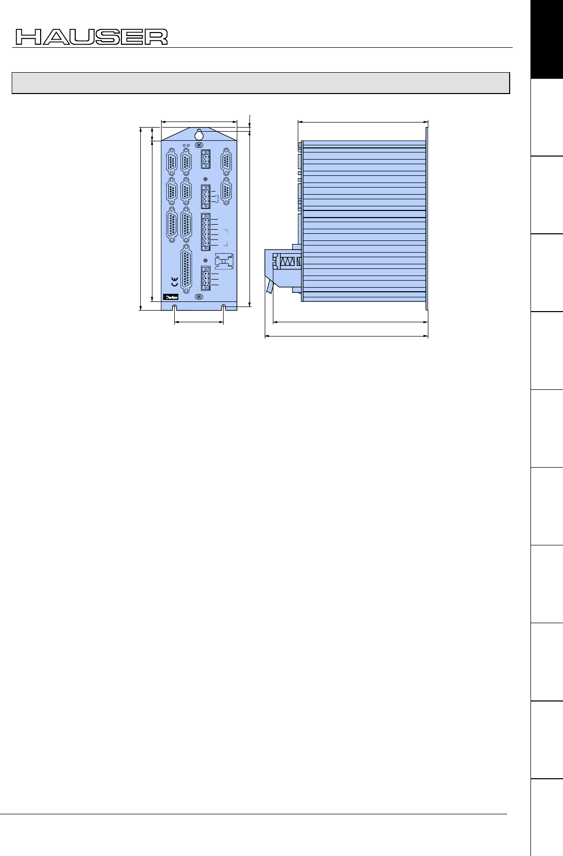
COMPAX 1000SL Unit characteristics
Mounting and dimensions COMPAX 1000SL
43
Unit
hardware
Connector
assignment / cable
Technical dataConfigurationPositioning and
control functions
Optimization
functions
InterfacesAccessories /
options
StatusParameterError list
7.7.3 Mounting and dimensions COMPAX 1000SL
Fieldbus InEncoder
Input / Output Resolver Fieldbus Out Limit Switch
24 V DC
RDump
H2
H1
RS232 X6X5X13
X12 X17
X19
X2 X1 X4 X3
X14 X15
HEDA Out HEDA In
Input
+-
L1 N PE UV
WPE + -
Motor Brake
PE
230 V AC
85
180
206.5
145.5
197.5
16
5
55 174
+-
COMPAX - SL
183
X7
Fastening: 3 M4 hex-socket head screws
Installation distance: 100mm (device distance:15mm)
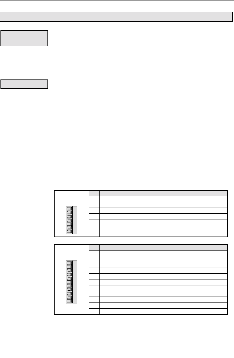
Start-up manual COMPAX-M / S
44
7.7.4 Safety chain / emergency stop functions
Establishing a safety chain for monitoring the drives and other control components
or a superordinate control unit usually requires a connection protected from wire
breaks. The contact outputs (closer) P (X8(9)/3) and S (X8(9)/4) are used for this
purpose. This closer establishes sequential switching for the mains module and the
axis controller. When the unit is operating correctly, the contacts are closed (P and
S are connected) and thereby indicate the readiness of the unit. If an error occurs
or if the drive system is switched off, the readiness is not displayed and the chain is
interrupted (see below).
The emergency stop input is used to activate or deactivate all drive controllers or
an individual controller supplied by the mains module. In accordance with the
safety chain described above, this input must be activated to power the motors.
This occurs either via an external contact between X8(9)/5 and X8(9)/6 (as is
shown in the figure below) or by applying voltage of between 15V and 24V to the
input X8(9)/6 against GND (X8(9)/2). If the contact is opened or the voltage is
removed from X8(9)/6 or routed to GND24V, the emergency stop sequence is
processed, e.g. all motors of the connected drive controller are decelerated and
switched off (no torque on the motor shaft); the ready contact drops.
! After an emergency stop: error E55 (even in OFF status) and O1="0". The current
command is interrupted.
! The controller brakes the motor (P10 = braking time from 100% speed to 0%).
! When at a standstill, the controller is switched off and any idle holding brake is
closed.
! Once the problem has been rectified, E55 must be acknowledged.
! The current command is continued after START.
NMD: X8
COMPAX-S: X9:
Pin Assignment
1 +24V DC (<50mA)
20V
3 P: Ready contact
4 S: Ready contact
5 +24V DC – Output for emergency stop
6 Emergency stop input (activated by 15V – 24V)
Connectors: Phoenix
MC1.5/7-ST-3.81
4567123
7 Screen
COMPAX 35XXM: X19
Pin Assignment
1 +24V DC (<50mA)
20V
3 P: Ready contact
4 S: Ready contact
5 +24V DC – Output for emergency stop
6 Emergency stop input (activated by 15V – 24V)
7 +24V DC (<50mA)
8 reserved
9 +24V DC (<50mA)
10 Enable
Connectors: Phoenix
MC1.5/7-ST-3.81
4567123 8 9 10 11
11 Screen
Readiness,
safety chain
Emergency stop
Emergency stop
characteristics :
Emergency stop
and ready on
connector:
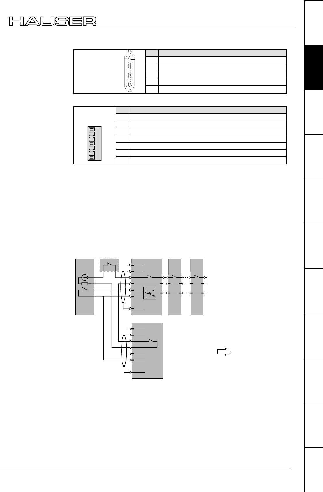
COMPAX 1000SL Unit characteristics
45
Unit
hardware
Connector
assignment / cable
Technical dataConfigurationPositioning and
control functions
Optimization
functions
InterfacesAccessories /
options
StatusParameterError list
COMPAX 1000SL X19
Pin Assignment
23 +24V DC (<50mA)
10V
24 P: Ready contact
25 S: Ready contact
25 pin Sub-D
socket strip
screw connection
UNC4-40
14
25
1
13 11 Emergency stop input (activated by 15V – 24V)
Emergency stop input direct to COMPAX-M X9
Pin Assignment
1 +24V DC (<50mA)
20V
3 reserved
4 reserved
5 +24V DC – Output for emergency stop
6 Emergency stop input (activated by 15V – 24V)
Connector: Phoenix
MC1.5/7-ST-3.81
4567123
7 Screen
*Emergency stop input on COMPAX-M
The emergency stop input on COMPAX-M X9 is enabled via parameter P219.
Meaning:
! P219="0": No emergency stop input on COMPAX-M X9
! P219="7": Emergency stop input on COMPAX-M X9 with the following data
! Stop with P10 as relative ramp time (P10 = braking time from 100% speed to
0%).
! The motor is switched off.
! Error message E56 is generated.
! The ready contact drops.
Ready contact: max. 0.5A,
60V, 30W
control power supply
module
COMPAX-M
No. 1
COMPAX-M
No. x
external
component
X8/1
X8/2
X8/3
X8/4
X8/5
X8/6
X8/7
+24V
GND
shield
readiness
emerg. stop
X./1
X./2
X./3
X./4
X./5
X./6
X./7
+24V
GND
shield
COMPAX-S X9 i.e. COMPAX 35XXM X19
Applies to potential -
24V power supply.
Principle of safety
chain and
emergency stop
function
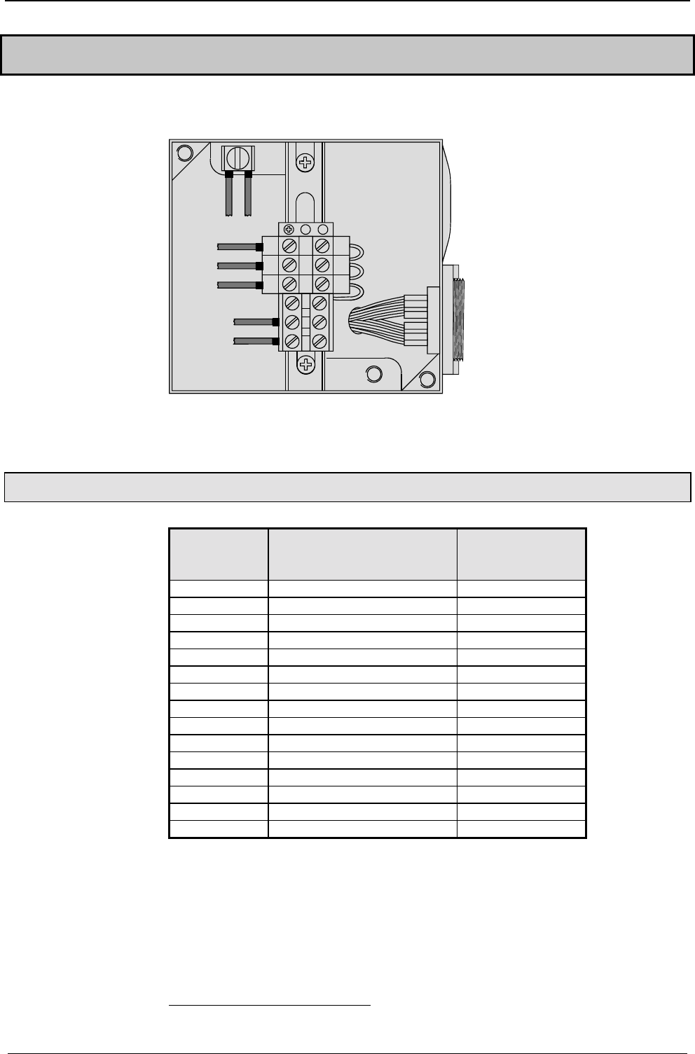
Start-up manual COMPAX-M / -S
Resolver / SinCos
46
7.8 Connections to the motor
black 5
black 4
brake
black 3
black 2
black 1
green/
yellow
PE
W
V
U
shield
black
7.8.1 Resolver / SinCos
Pin from X12 Standard assignment
Assignment with resolver
or option S1/ S22
Assignment with
option S33
1 Housing Housing
2+8V +8V
3NC HALL3
4REF- +5V
5 SIN- SIN- / A/
6NC HALL2
7 GND GND
8ST+ +5V
9+5V +5V
10 TEMP TEMP
11 COS- COS- / B/
12 COS+ COS+ / B
13 SIN+ SIN+ / A
14 REF+ HALL1
15 ST- GND HALL
2 The S1/2 options are required for operation with the sensor system SinCos.
3 The S3 option is required for operation of linear motors.
Cable assignment
in the terminal
boxes
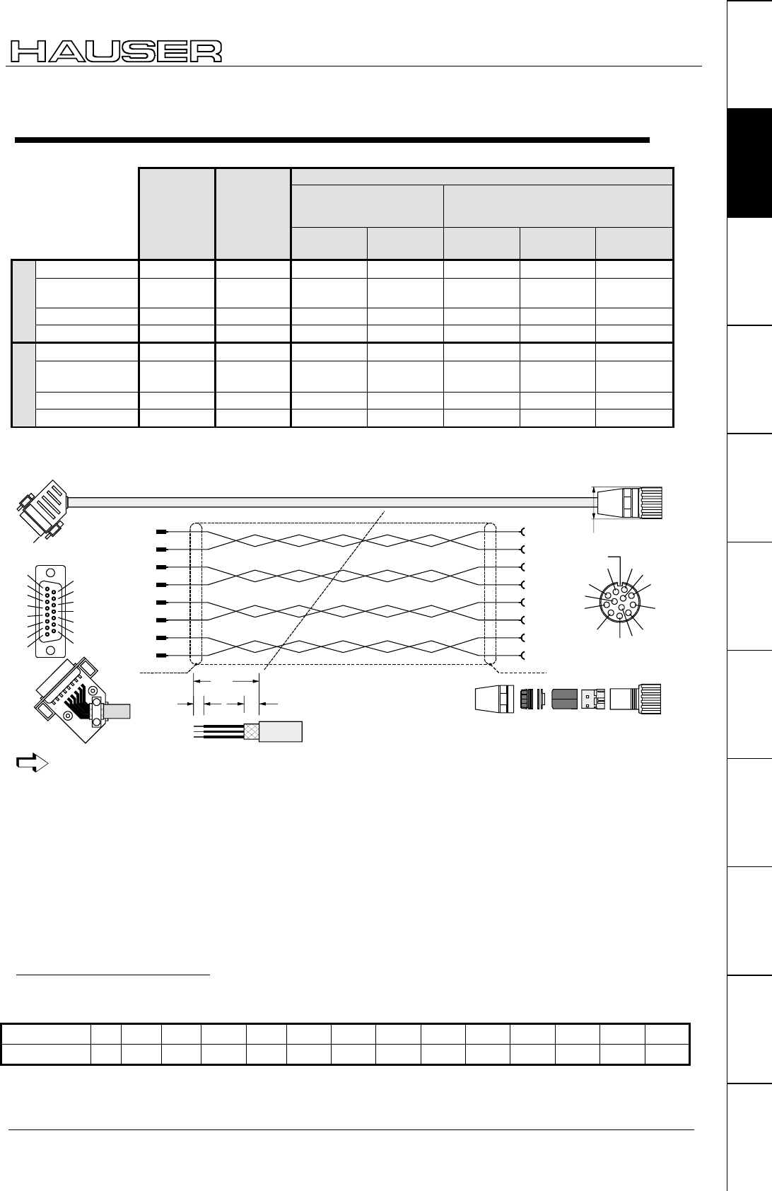
Connections to the motor
47
Unit
hardware
Connector
assignment / cable
Technical dataConfigurationPositioning and
control functions
Optimization
functions
InterfacesAccessories /
options
StatusParameterError list
Length codes for preformed cables
Length [m] 1.0 2.5 5.0 7.5 10.0 12.5 15.0 20.0 25.0 30.0 35.0 40.0 45.0 50.0
Code 01 02 03 04 05 06 07 08 09 10 11 12 13 14
Example REK32/09: length 25m
Connecting cable to motor
Motor cable
With connectors:
HJ96, HJ116, HDY55,
HDY70, HDY92, HDY115
With terminal boxes:
HJ155, HJ190
HDY142
Resolver
cable
Sensor
cable
(SinCos
)1.5mm2
up to 13.8A
2.5mm2
up to 18.9A
2.5mm2
up to 18.9A
6mm2
up to 32.3A
10mm2
up to 47.3A
Cable sheathed REK32/.. GBK16/.. MOK42/.. MOK43/.. MOK21/.. MOK11/.. MOK46/..
Connector set 085-301312
800-030031
085-301317
800-030031
085-301306 085-301306 125-518162
125-216800
125-518211
125-217000
125-518200
Cable 102-150200 102-150210 102-508896 102-508902 102-508902 102-150030 102-150040
Standard cable
Cable data in mm 18,0/80/120 7,5/38/113 10,7/107/107 13,7/137/137 13,7/137/137 16,5/124/124 22,5/168/168
Cable sheathed REK33/.. GBK17/.. MOK44/.. MOK45/.. MOK14/.. MOK11/.. MOK46/..
Connector set 085-301312
800-030031
085-301317
800-030031
085-301306 085-301306 125-518162
125-216800
125-518211
125-217000
125-518200
Cable 102-000030 - 102-000020 102-000010 102-000010 102-150030 102-150040
High-flex cable
Cable data in mm *8,2/61,5/61,5 8,0/40/64 9,2/69/69 11/82,5/82,5 11/82,5/82,5 16,5/124/124 22,5/168/168
Resolver cable for HJ and HDY motors
12
11 12
11
5
13 2
1
gr
rs
gn
rt
bl
ws
br
ge
10
7
Ref+
Ref-
9
8+Temp
-Temp
COS-
COS+
SIN-
SIN+
REK32
Li2YCY 4x2x0,25
No. 102-150200
2x0,25
2x0,25
2x0,25
2x0,25
Pin 1
grey
pink
green
red
blue
white
brown
yellow
4
14
Ref+
Ref-
10
9
+Temp (+5V)
-Temp
COS-
COS+
SIN-
SIN+
solder side
1
2
3
4
5
10
11
12
13
6
7
8
14
15
9
98
7
6
5
4
3
2
1
12
11
10
Codiernut 20°
solder side
4 mm 6 mm
26 mm
27
In HJ – motors, ensure that the thermal sensor has the correct terminal arrangement.
Version in high-flex: REK33 (same layout)
Packaging
Packaging of motor in accordance with connector manufacturer's specification
Packaging of device
• Strip 26mm sheathing off.
• Cut sheath down to 6 mm.
• Strip 4mm of insulation of ends and coat in tin.
*1 Cable diameter / minimum bending radius (static) / minimum bending radius (dynamic)
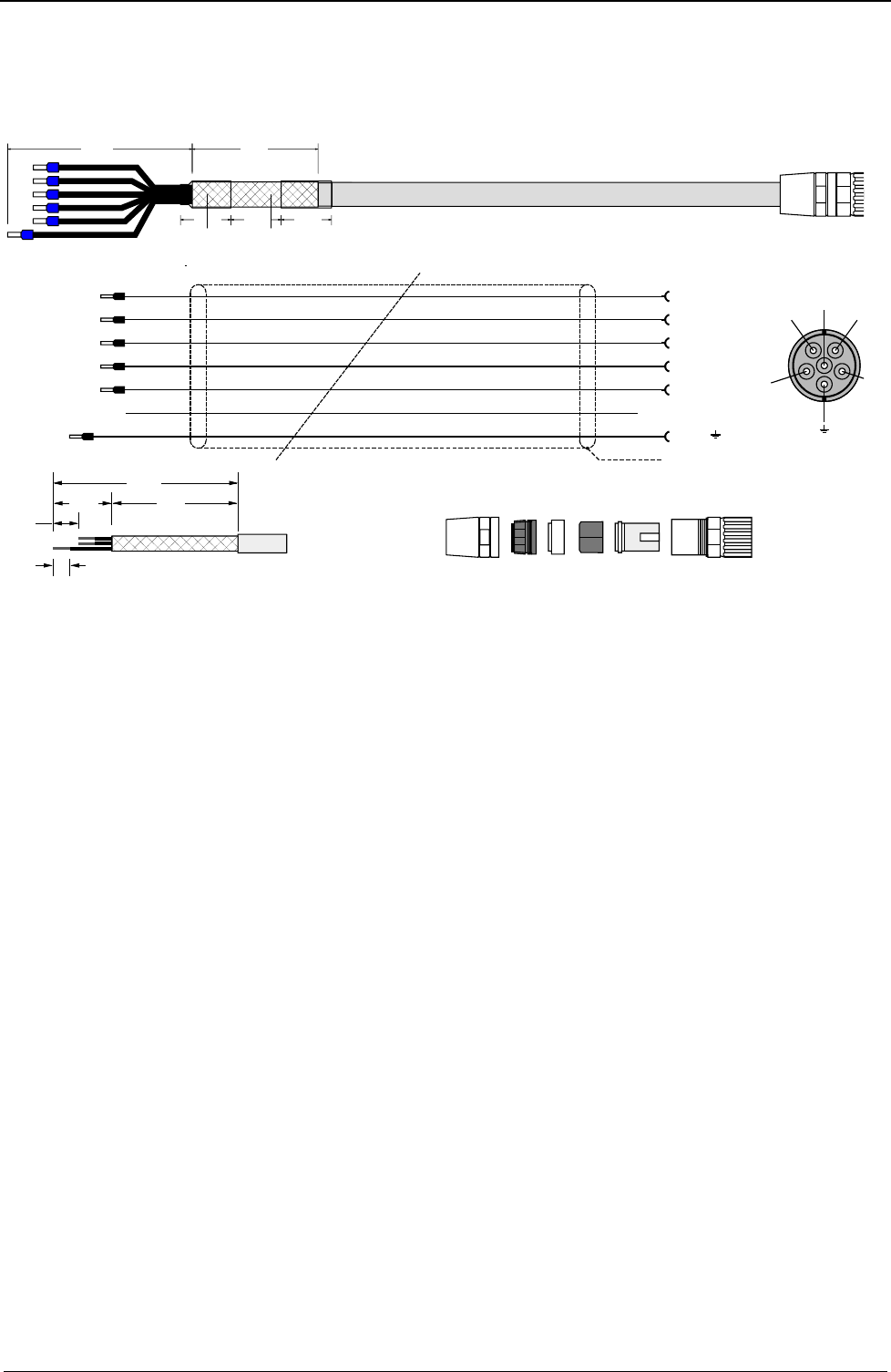
Start-up manual COMPAX-M / -S
Resolver / SinCos
48
Motor cable for HJ and HDY – motors
MOK42 (max. 13,8A)
MOK42
CY-JZ 7x1,5
No 102-508896
PE
Br. -24V
Br. +24V
W
V
U
6
5
2
1
3
4
sw1/sw
sw2/br
sw3/bl
sw4/rt
sw5/gr
sw6
gn/ge
standard/hochflex
Br-
Br+
W
V
ULötseite / Crimpseit
e
6
4
1
5
3( )
30 mm30 mm30 mm
110 mm 75 mm
110 mm
75 mm
35 mm
15 mm
10 mm
black1/black
black2/brown
black3/blue
black4/red
black5/green
black6
green-yellow
standard/highflex
Version in high-flex: MOK44 (same layout)
MOK43/.. (max. 18.9A): HJ (version in high-flex: MOK45)
Layout corresponds to MOK42, however motor lines in 2.5 mm2
Packaging
Packaging of motor in accordance with connector manufacturer's specification
Contacts for 1.5 mm2 and 2.5 mm2 are supplied with the connector set.
Packaging of device
Material:
• 6 x crimping sleeves.
• 6 cm shrink-fit hose.
Procedure:
• Strip 110 mm sheathing off cable.
• Cut down sheath to approx. 35 mm, loosen,
• fold back over outer cover (approx. 75 mm) and stick with insulating tape.
• Shorten sw1,sw2,sw3,sw4,sw5 approx. 15 mm ; (gn/ge approx. 15 mm longer); cut down sw6.
• Attach 2 x approx. 30 mm shrink-fit hose (sticky).
• Strip 10 mm of insulation of ends of wires and secure with crimping sleeve 1.5.
Shrink-fit hose
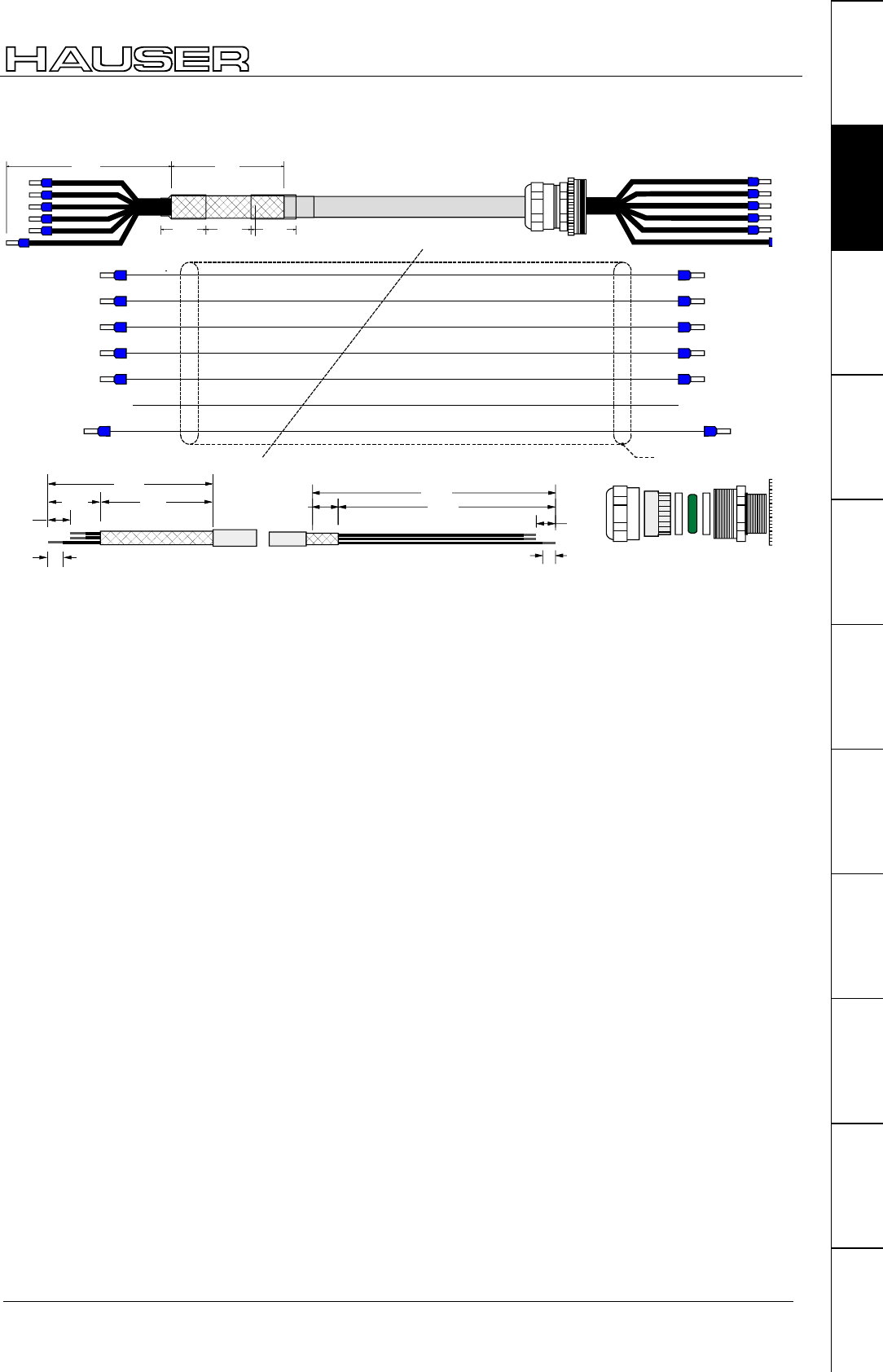
Connections to the motor
49
Unit
hardware
Connector
assignment / cable
Technical dataConfigurationPositioning and
control functions
Optimization
functions
InterfacesAccessories /
options
StatusParameterError list
MOK21 (max. 18,9A)
CY-JZ 7x2,5
No. 102-508902
PE
Br. -24V
Br. +24V
W
V
U
PE
Br-
Br+
W
V
U
MOK21
30 mm30 mm30 mm
110 mm 75 mm
110 mm
75 mm
35 mm
15 mm
10 mm
190 mm
20 mm 170 mm
15 mm
10 mm
sw1/sw
sw2/br
sw3/bl
sw4/rt
sw5/gr
sw6
gn/ge
standard/hochflex
black1/black
black2/
brown
black3/blue
black4/red
black5/
green
black6
green-yellow
standard/highflex
Version in high-flex: MOK14 (same layout)
MOK11 (max. 32.3A) in high-flex (same layout to MOK21, however in 6 mm2)
MOK46 (max. 47.3A) in high-flex (same layout to MOK21, however in 10mm2)
Packaging
Packaging of device
Material:
6 x crimping sleeves.
6 cm shrink-fit hose.
Procedure:
• Strip 110 mm sheathing off cable.
• Cut sheath down to approx. 35 mm, loosen,
• fold back over outer cover (approx. 75 mm) and stick with insulating tape.
• Shorten sw1,sw2,sw3,sw4,sw5 ca. 15 mm (gn/ge approx. 15 mm longer) cut down sw6.
• Attach 2 x approx. 30 mm shrink-fit hose (sticky).
• Strip 10 mm of insulation off ends of wires and secure with crimping sleeves 2.5.
Packaging of motor in accordance with manufacturer's specification
• Strip 190 mm sheathing of cable.
• Cut sheath down to approx. 170 mm, stick remaining 20 mm with insulating tape.
• Shorten sw1,sw2,sw3,sw4,sw5 by approx. 15 mm (gn/ge approx. 15 mm longer) cut down sw6.
• Strip 10 mm of insulation of ends of wires and secure with crimping sleeves 2.5.
Shrink-fit hose
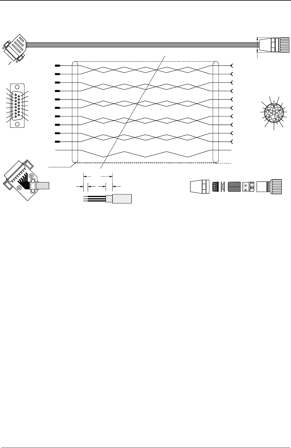
Start-up manual COMPAX-M / -S
Resolver / SinCos
50
SinCos
cable for HJ and HDY motors
2
7
10
7
+8V
GND
+V
GND
9
10 9
8
Th1
Th2
K1
K2
15
8
13
3
ST-
ST+ +485
-485
12
11 12
11
COS-
COS+
COS-
COS+
5
13
0r
red
blue
green
grey
pink
black
white
brown
violet
yellow
2
1
0r
rt
bl
gn
gr
rs
sw
ws
br
vio
ge
SIN-
SIN+
SIN-
SIN+
screen at
sceen contact
LiYC11Y 4x2x0,25+2x0,5+0,14
No. 102-150210
2x0,5
1x0,14
2x0,25
2x0,25
2x0,25
2x0,25
solder side
1
2
3
4
5
10
11
12
13
6
7
8
14
15
9
Pin 1
Packing according as the regulation of the manufacturer
solder- / Crimp side
84
657
3
2
1
9
16
11
10 12
13
15 14
17
8 x Crimp contacts 0.14-0.56
GBK16
4 mm 6 mm
26 mm
27
Version in high-flex: GBK17 (same layout)
Packaging
Packaging of motor in accordance with connector manufacturer's specification
Packaging of device
• Strip 26mm sheathing off.
• Cut sheath down to 6 mm.
• Strip 4mm of insulation of ends and coat in tin.
• Place sheath over large area of housing (e.g. fold sheath over outer cover and fasten down by relieving tension).
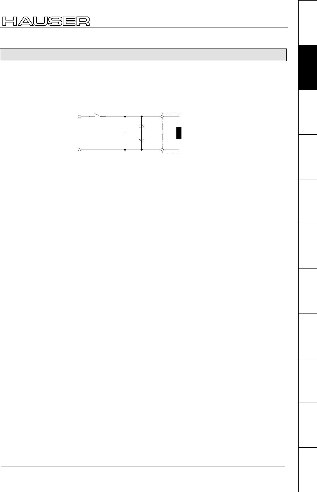
Connections to the motor
51
Unit
hardware
Connector
assignment / cable
Technical dataConfigurationPositioning and
control functions
Optimization
functions
InterfacesAccessories /
options
StatusParameterError list
7.8.2 Additional brake control
COMPAX controls the motor retaining brake independently (also see Page 123).
When running applications which require additional brake control note the
following, based on the unit type used.
With these units, you must implement measures for suppression. Note the
following application example:
Br.+
BR.-
33V
33V
0,47uF
contact to external
brake control stop
brake
within
motor
These protective measures are available in COMPAX-M / COMPAX 45XXS /
COMPAX 85XXS for applications without external brake control.
In COMPAX 25XXS (X1/7 and X1/8) and in COMPAX 35XXM (X23: bridge), 2
connections are available for connecting the external contact. These connections
are already bridged in the connector when supplied.
External protective measures are not required for COMPAX 25XXS and COMPAX
35XXM.
External contact connection:
The bridge is removed and is replaced by connecting an external contact.
COMPAX-M /
COMPAX 45XXS /
COMPAX 85XXS,
COMPAX 1000SL
COMPAX 25XXS /
COMPAX 35XXM
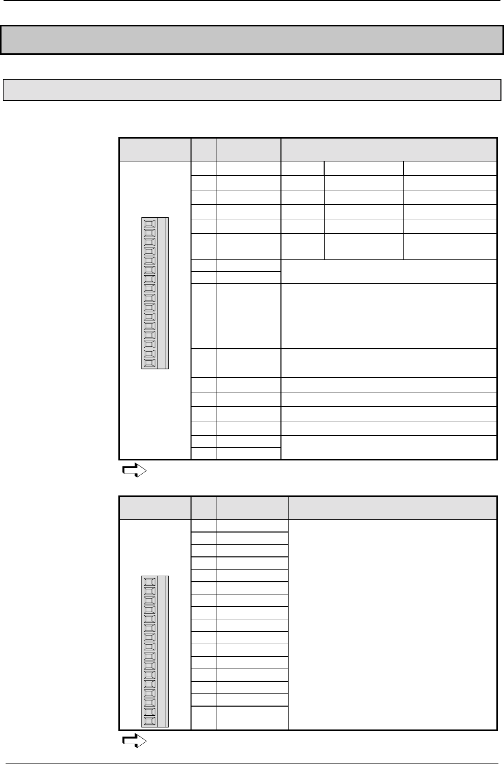
Start-up manual COMPAX-M / -S
Digital inputs and outputs (excluding COMPAX 1000SL)
52
7.9 Interfaces
7.9.1 Digital inputs and outputs (excluding COMPAX 1000SL)
The inputs and outputs have PLC voltage levels (High signal = 24V DC)
X8
Pin
Assignment Meaning
1. Input I1 SHIFT ="0" ="1"
2. Input I2 Manual+ Find machine zero
3. Input I3 Manual– Approach real zero
4. Input I4 Quit Teach real zero
5. Input I5 Start -
6. Input I6 Stop (interrupt
data record)
Break (breaks off
data record)
7. Input I7
8. Input I8
Freely assignable in the standard unit.
9. Output O1 ="1":No fault
="0":errors E1 ... E58; the drive does not
accept any positioning commands.
After "Power on" O1 remains at "0" until after
the self test.
10. Output O2 ="1":No warning
="0":error ≥ E58
11. Output O3 Machine zero has been approached
12. Output O4 Ready for start
13. Output O5 Programmed set point reached
14. Output O6 Idle after stop
15. Output O7
Connectors:
Phoenix
MC1.5/16-ST-
3.81
4 5 6 7 8 9 10111213141516123
16. Output O8
Freely assignable in the standard unit.
The "SHIFT signal" (I1) must be assigned before or at the same time as the
relevant input.
X10
Pin
Assignment Meaning
1. Input I9
2. Input I10
3. Input I11
4. Input I12
5. Input I13
6. Input I14
7. Input I15
8. Input I16
9. Output O9
10. Output O10
11. Output O11
12. Output O12
13. Output O13
14. Output O14
15. Output O15
Connector:
Phoenix
MC1.5/16-ST-
3.81
4 5 6 7 8 9 10111213141516123
16. Output O16
Freely assignable in the standard unit.
Note the assignment for unit variants and for special functions.
Assignment of X8
(Input/Output)
Assignment of
X10 (Input/Output)
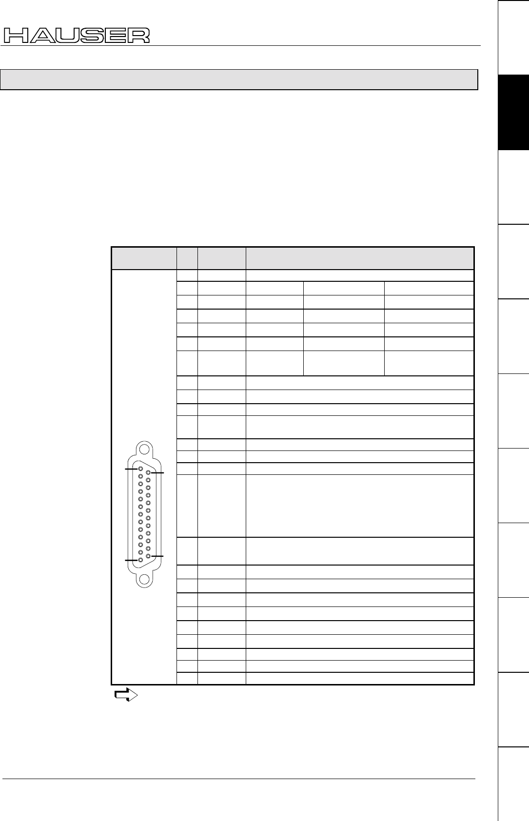
Interfaces
53
Unit
hardware
Connector
assignment / cable
Technical dataConfigurationPositioning and
control functions
Optimization
functions
InterfacesAccessories /
options
StatusParameterError list
7.9.2 Digital inputs and outputs for COMPAX 1000SL
COMPAX 1000SL physically has 8 digital inputs and 8 digital outputs which are
assigned to connector X19.
COMPAX internally has 16 logic inputs and 16 logic outputs, some of which have
functions assigned to them. This means that not all logic inputs and outputs can be
interrogated or output via physical inputs and outputs. In order to enable flexible
assignment, a matrix was created for input and output assignment respectively
which makes it possible to assign the logic inputs and outputs to any of the
physical inputs and outputs. The matrices for allocation are realized via parameters
P156 to P160 (see Page 140). The assignment described below applies to
COMPAX 1000SL (standard unit) with default settings for parameters P156 to
P160.
X19
Pin
Assign-
ment
Meaning for COMPAX 1000SL standard unit and default
settings for parameters P156 to P160
1. GND
2. Input SHIFT ="0" ="1"
3. Input Manual+ Find machine zero
4. Input Hand– Approach real zero
5. Input Quit Teach real zero
6. Input START -
7. Input Stop (interrupts
data record)
Break (breaks off
data record)
8. Input Freely assignable in the standard unit. (I12)
9. Input Freely assignable in the standard unit. (I16)
10. reserved
11. Emergen
cy stop
Emergency stop input (emergency stop is triggered
by voltage < 15V DC)
12. Enable COMPAX 1000SL is enabled by 24V DC at X19/12
13. Override Input voltage 0 - +5V.
14. GND
15. Output ="1":No fault
="0":errors E1 ... E58; the drive does not accept
any positioning commands.
After "Power on" O1 remains at "0" until after the
self test.
16. Output ="1":No warning
="0":Error ≥ E58
17. Output Machine zero has been approached
18. Output Ready for start
19. Output Programmed set point reached
20. Output Idle after stop
21. Output Freely assignable in the standard unit. (O7)
22. Output Freely assignable in the standard unit. (O8)
23. 24VDC Load < 50mA
24. Ready P Ready contact for building a safety chain
25 pin Sub-D
socket strip
screw
connection
UNC4-40
14
25
1
13
25. Ready S Ready contact for building a safety chain
Note the assignment for unit variants and for special functions.
Assignment X19
for COMPAX
1000SL
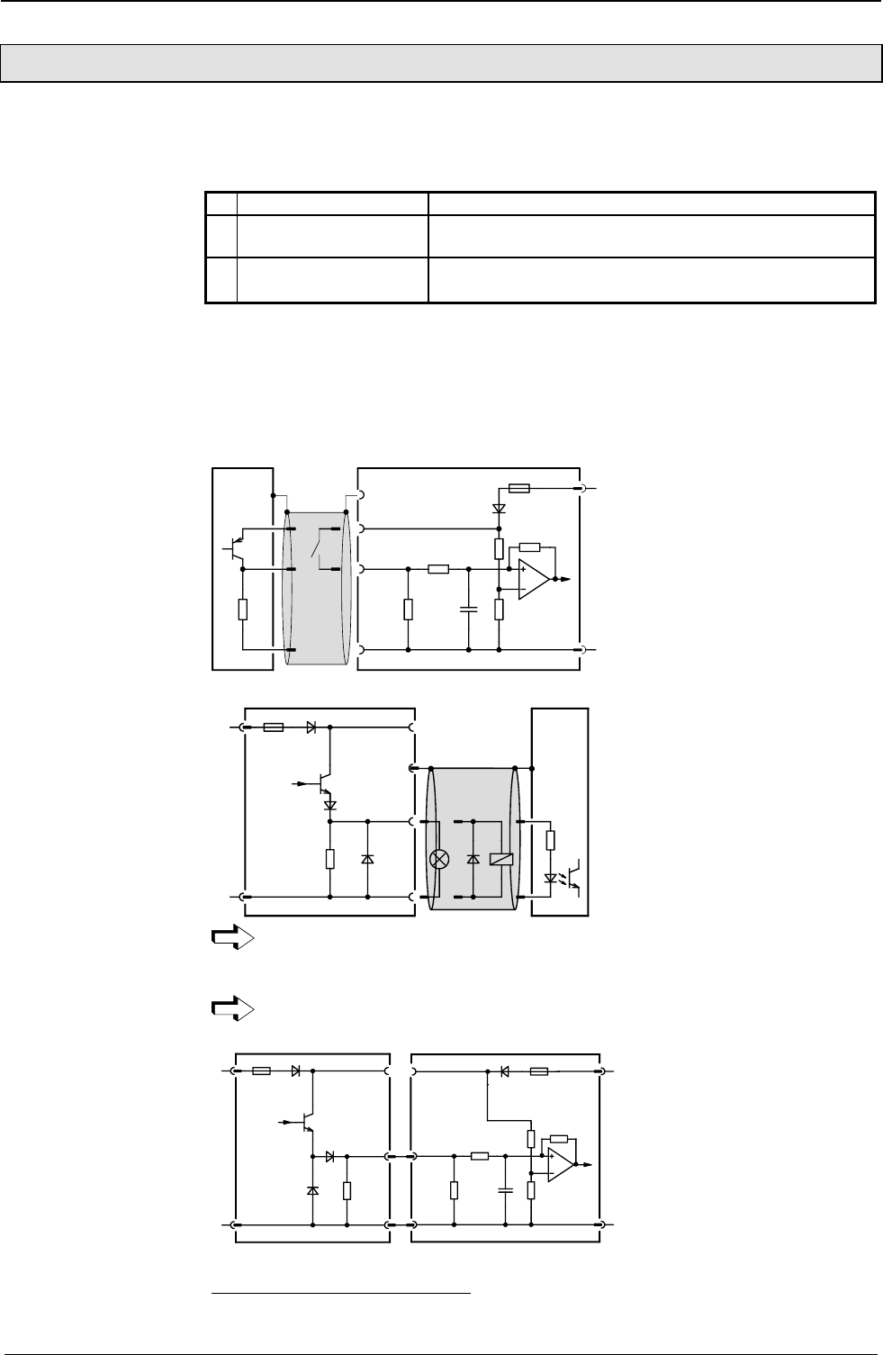
Start-up manual COMPAX-M / -S
Technical data / Connections of inputs and outputs
54
7.9.3 Technical data / Connections of inputs and outputs
0 → 1 over 9.15V means that "1" is recognised
1 → 0 over 8.05V means that "0" is recognised
1. O1...O16 Total of max. 1.6A
2. O1...O4, O5...O8,
O9...O12, O13...O16
Per group of 4, max. 0.8A; taking due account of 1.
3. O per output, max. 0.3A and 40nF capacitive4; taking
into account 1. and 2.
Per output, max. 0.3A • In total a sum load for all 8 outputs of max. 0.48A and
40nF capacitive5;
If overload occurs, an error message appears (E43: can be acknowledged with
Power off/on); the corresponding group of four is switched off.
10nF
22KΩ
12KΩ
F23
22KΩ
X8/7
PLC
24V
0V
X11/1
X11/2
22KΩ
X11/7
100KΩ
X19/23
X19/14
X19/.
(X19 applies for COMPAX 1000SL)
F23
PLC
24V
0V
X8/15
4.7KΩ
X19/14
X11/1
X11/2
X11/7
X19/23
X19/.
(X19 applies for COMPAX 1000SL)
For reasons of interference protection, we would recommend that you use a
screened cable for the digital inputs and outputs.
With COMPAX 1000SL, the screen is connected with the Sub-D housing.
A protective connection is required when there is inductive load present.
F23
24V
0V
X8/15
4.7KΩ
X19/23
X19/14
X11/1
X11/2
10nF
22KΩ
12KΩ
22KΩ
X8/7
24V
0V
X11/2
22KΩ
F23
100KΩ
X19/.
X19/14
X19/.
X19/23
X11/1
(X19 applies for COMPAX 1000SL)
4 A maximum of 4 COMPAX – inputs can be connected to one output.
5 A maximum of 4 COMPAX – inputs can be connected to one output.
Detection of input
signals:
Load on outputs
(not applicable for
COMPAX 1000SL):
Load on outputs for
COMPAX 1000SL:
Input connection
using I7 as an
example
Output connection
using O7 as an
example
Input/output
connection for
2 COMPAXs
1st COMPAX 2nd COMPAX
COMPAX
COMPAX
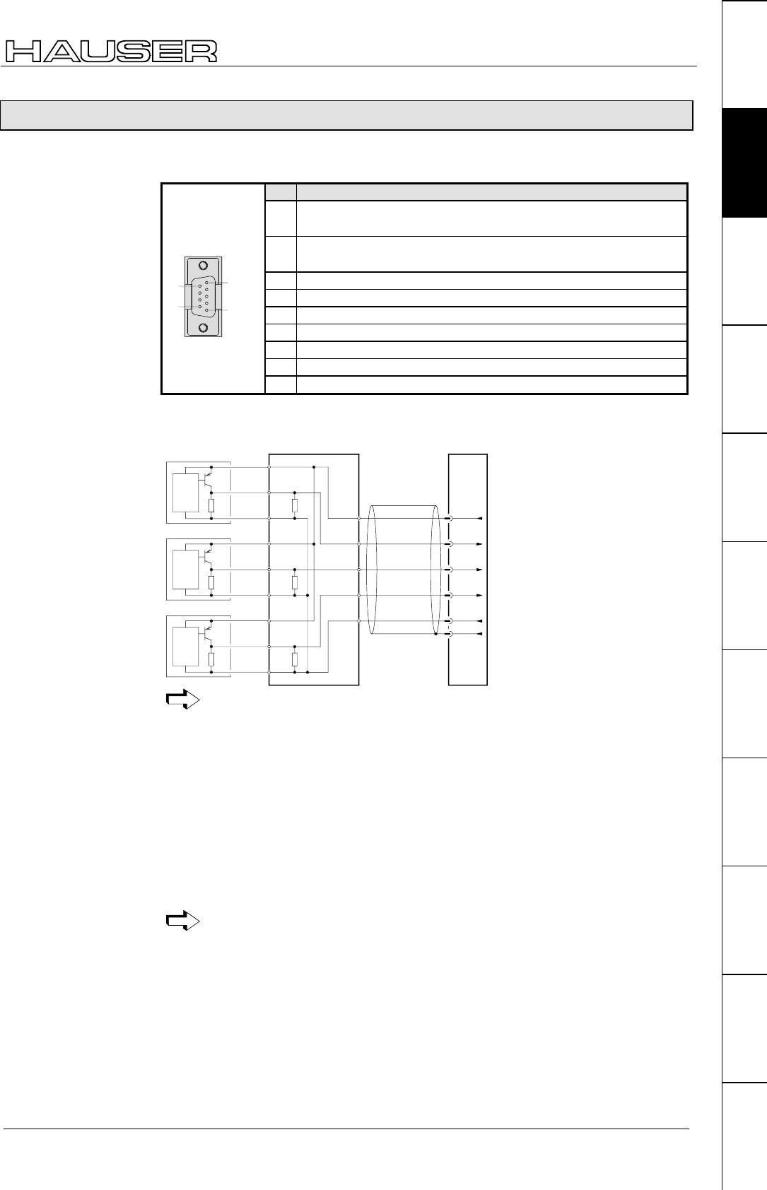
Interfaces
55
Unit
hardware
Connector
assignment / cable
Technical dataConfigurationPositioning and
control functions
Optimization
functions
InterfacesAccessories /
options
StatusParameterError list
7.9.4 Initiators and D/A monitor
Connection assignment on X17
Pin Assignment
1DA channel 0 (option D1) Ri=2.8kΩ;
COMPAX 1000SL: DA channel 2; Ri=0.33kΩ;
2DA channel 1 (option D1) Ri=2.8kΩ;
COMPAX 1000SL: DA channel 3; Ri=0.33kΩ;
3 reserved
4 Ground 24V (Initiators supply)
5 +24V (Initiators supply) <50 mA
6 Ground for DA channels
7 Input MZ initiator
8 Input I2 initiator
9 pin Sub-D pin strip
plug housing with
screw connection
UNC4-40
1
5
6
9
9 Input I1 initiator
X3/9
X3/8
X3/7
X2/6
X2/5
X2/4
X1/3
X1/2
X1/1
X4/15
X4/14
X4/13
X4/12
X4/10
+24V
Sig. MN
GND
initiatorbox
X17/5
X17/9
X17/7
X17/8
X17/4
X17/3
+24V
Sig. E1
Sig. MN
Sig. E2
GND
br
sw
bl
br
ge
gn
ws
bl
E1
E2
4,75kΩ4,75kΩ4,75kΩ
+24V
Sig. E2
GND
br
sw
bl
normally
closed pnp
+24V
Sig. E1
GND
br
sw
bl
MN
normally
closed pnp
normally
closed pnp
Ensure that the initiator is rebound-free!
Standard
When operating with one initiator (machine zero), this must be attached to one
side of the stroke. When attaching the initiator, ensure that an initiator attached to
the left-hand side can no longer be cleared to the left. The flank to be analyzed can
therefore also be positioned before the end of the travel distance. The same
applies correspondingly for the right-hand side.
Extended operation
When operating with three initiators (not standard), initiators I1 and I2 must be
attached to the outer limits of the stroke range. The machine zero initiator is fitted
between I1 and I2. The following limitation applies in such cases: the flank of the
machine zero initiator must not be activated at the same time as a limit switch.
If COMPAX is only operating as a speed controller or in the "continuous
mode" or normal operating mode with a special machine zero mode
(P212="10" see Page 80 onwards), then no initiators are required.
Connection plan
for the initiators
with initiator
connector
Requirements
concerning the
position of the
initiators
COMPAX
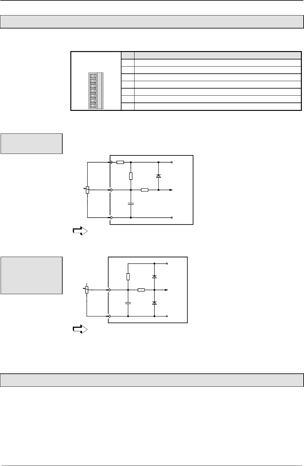
Start-up manual COMPAX-M / -S
Service D/A monitor / override
56
7.9.5 Service D/A monitor / override
Assignment of X11 (not applicable for COMPAX 1000SL)
Pin Assignment
1 +24V
2 Ground 24V
3 Override for speed reduction
4Standard DA channel 2: 8 Bit, Ri=2.21kΩ;
5Standard DA channel 3: 8 Bit, Ri=2.21kΩ;
6 Override; previous input for existing applications
Connector: Phoenix
MC1.5/7-ST-3.81
4567123
7 Screen
With COMPAX 1000SL, the override input is on X19/13 (see Page 53),
the Service D/A monitors on X17/1 und X17/2 (see Page 55).
(not applicable for COMPAX 1000SL)
X11/3
X11/2
1KΩ
10KΩ
+5V
GND
100%
0% 10KΩ
100nF
X11/6
10KΩ
Override-
Signal
The override input is read in a cycle of 100 ms.
You can continue to use the previous override connection for current applications.
X19/13
X19/14
10KΩ
+5V
GND
100%
0% 10KΩ
100nF
Override-
Signal
1KΩ
The override input is read in a cycle of 100 ms.
Wiring of override with screened cables only
7.9.6 Service D/A monitor
The service D/A monitor gives you the option of outputting internal measurement
and intermediate parameters from COMPAX in the form of analogue voltage in the
range of ±10V via X11 (X17 with COMPAX 1000SL) and visualizing these by
means of an oscilloscope. This provides you with a capable aid for making the unit
functions clear and qualifiable, especially during the start-up.
This function (which is available in all units) provides you with two analogue output
channels with a resolution of 8 bit and these are updated every 100 µs.
Override
connection
Override -
Connection for
COMPAX
1000SL
Note:
COMPAX
COMPAX 1000SL
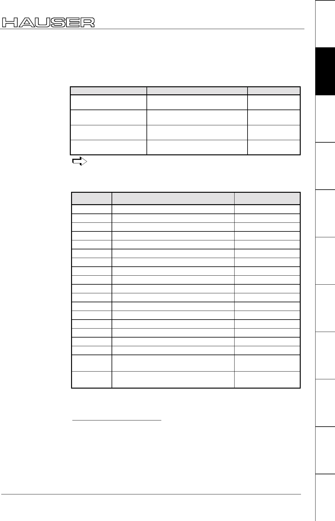
Interfaces
57
Unit
hardware
Connector
assignment / cable
Technical dataConfigurationPositioning and
control functions
Optimization
functions
InterfacesAccessories /
options
StatusParameterError list
Using the parameters P76 and P77, you can select 2 parameters and adapt them
to the required measuring range.
Channel 2: X11/4; X17/1 for COMPAX 1000SL6
Channel 3: X11/5; X17/2 for COMPAX 1000SL
No. Parameter Range
P76
Value before decimal p.
Measuring parameter of channel 2.
(see below for meaning).
0...18
P76
Value after decimal point7
Gain factor from channel 2.
(factor = value * 10 000 000)
0.1... 10 000 000
P77
Value before decimal p.
Measuring parameter of channel 3.
(see below for meaning).
0...18
P77
Value after decimal point
Gain factor from channel 3.
(factor = value * 10 000 000)
0.1... 10 000 000
The parameters can only be actuated once you have entered the password.
They are validated using VP.
Service D/A monitor: Selection of measuring parameter using P76 / P77
D/A monitor (option D1): Selection of measuring parameter using P73 / P74
Measuring
parameter No. Measuring parameter Reference value8
0 Nominal speed value sensor 20 000 min-1
1 Tracking error 128›Motor revolutions
2 Advance speed control 20 000 min-1
3 Nominal speed value of position controller 20 000 min-1
4 Actual speed value 20 000 min-1
5 Speed deviation 20 000 min-1
6 Not assigned
7 Not assigned
8 Nom. value of transverse current (torque)9200A
9 Intermediate circuit voltage 1000V
10 Sine for co-ordinate transformation
11 Voltage positioning signal for phase U 2 * ULS
12 Voltage positioning signal for phase V 2 * ULS
13 Phase current for phase U 200A
14 Phase current for phase V 200A
15 Actual value of transverse current (torque)10 200A
16 Longitudinal current 200A
17 Scaled transverse voltage
(For amplification of 1 use: 10V = 2 * ULS )
2 * ULS
18 Scaled longitudinal voltage
(For amplification of 1 use: 10V = 2 * ULS )
2 * ULS
You will find additional measuring parameters on Page 210!
6 The initiator signals are looped through the monitor box ASS1/01.
7 .0000001=factor 1
.000001=factor 10
.999999=factor 10 000 000
8 Physical value with 10V output voltage and an amplification of 1
9 To determine torque:
torque = transverse current * 0.71 * total torque constant
10 To determine torque:
torque = transverse current * 0.71 * total torque constant
Assignment of the
channels
Meaning and
range of values of
P76 / P77
D/A monitor
standard
measuring
parameters
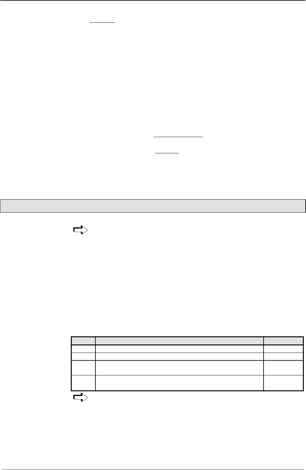
Start-up manual COMPAX-M / -S
D/A monitor option D1
58
10V*VS
BG*MW
PG =
PG: physical parameter
MW: voltage on output channel in [V]
BG: reference value from the above table
VS: gain factor
P76 = 4.000 0010 P77 = 13.000 0005
Therefore the following applies:
channel 2: measuring parameter 4 (actual speed value).
gain factor = 10
channel 3: measuring parameter 13 (phase current for phase U).
gain factor = 5
measured values:
channel 0:MW=2.5V=> 10V*10
20000min*2,5
PG
1
−
==500 rpm
channel 1: MW = 3V => 10V*5
200A*3
PG = = 12A
The parameters of the D/A monitor can also be set to status S15 or be viewed via
the optimization display (see Page 133).
7.9.7 D/A monitor option D1
The option D1 cannot be used for COMPAX 1000SL.
This option provides you with two additional analogue output channels with a
resolution of 12 bit. These channels are updated every 100 µs. Use the parameters
P73 and P74 (as you do with the service D/A monitor) to select 2 quantities and to
adapt them to the required measuring range using 2 parameters (P71 and P72).
D/A monitor option D1 must be ordered as a separate item.
To obtain output from the measured signals, you will need an externally connected
monitor box (ASS1/01) with 2 BNC bushes for connecting the measurement
instruments. This is connected as follows:
! monitor box is connected to COMPAX connector X17.
! the initiator line is connected from X17 to the monitor box. The signals are fed
through the monitor box.
Meaning and range of values of P71 - P74
No. Parameter Range
P71 Gain factor from channel 0. 1...10 000
P72 Gain factor from channel 1. 1...10 000
P73 Measuring parameter of channel 0. (For the meaning, see
table on Page 56).
0...18
P74 Measuring parameter of channel 1. (For the meaning, see
table on Page 56).
0...18
The parameter can only be actuated once you have entered the password.
Example:P71=10 P72=5 P73=4 P74=13
Therefore, the following applies:
channel 0: measuring parameter 4 (actual speed value).
gain factor = 10
channel 1: measuring parameter 13 (phase current for phase U).
gain factor = 5
Calculation of
physical parameter
using the measured
value:
Example:
The measuring
parameters are
selected using P73
or P74
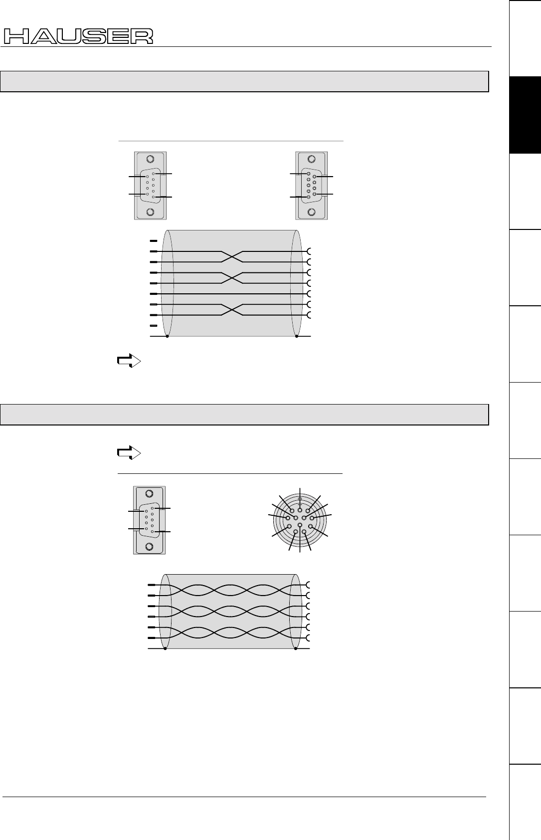
Interfaces
59
Unit
hardware
Connector
assignment / cable
Technical dataConfigurationPositioning and
control functions
Optimization
functions
InterfacesAccessories /
options
StatusParameterError list
7.9.8 RS232 interface
Wiring diagram SSK1/...:COMPAX - PC/terminal
PC / terminal
9-way Sub-D-pin
plug shell with screwed
connection UNC4-40
9pol. Sub-D-socket board
housing
GND
housing
GND
7 x 0.25mm + shield
2
2
3
4
6
5
7
8
RxD
TxD
DTR
DSR
RTS
CTS
2
3
4
6
5
7
8
RxD
TxD
DTR
DSR
RTS
CTS
9+5V
1n.c.
1
5
6
9
1
5
6
9
X6
Apply screen on both sides to surface.
7.9.9 Absolute value sensor (option A1)
The option A1 cannot be used for COMPAX 1000SL.
X16
11
3
10
2
1
8
1
2
3
4
5
6
7
8
9
10
11
12
1
5
6
9
T+
T-
D+
D-
+24V
GND
6
1
8
3
9
5
2
4
7
n.c.
n.c.
n.c.
absolute enoder
plug :
9-way Sub-D-pin
plug housing with
screwed connection
UNC4-40
plug :
C12FUR
4 x ( 2 x 0.25mm ) + shield
2
housing housing
Cable plan
GBK1/..: COMPAX
absolute value
sensor
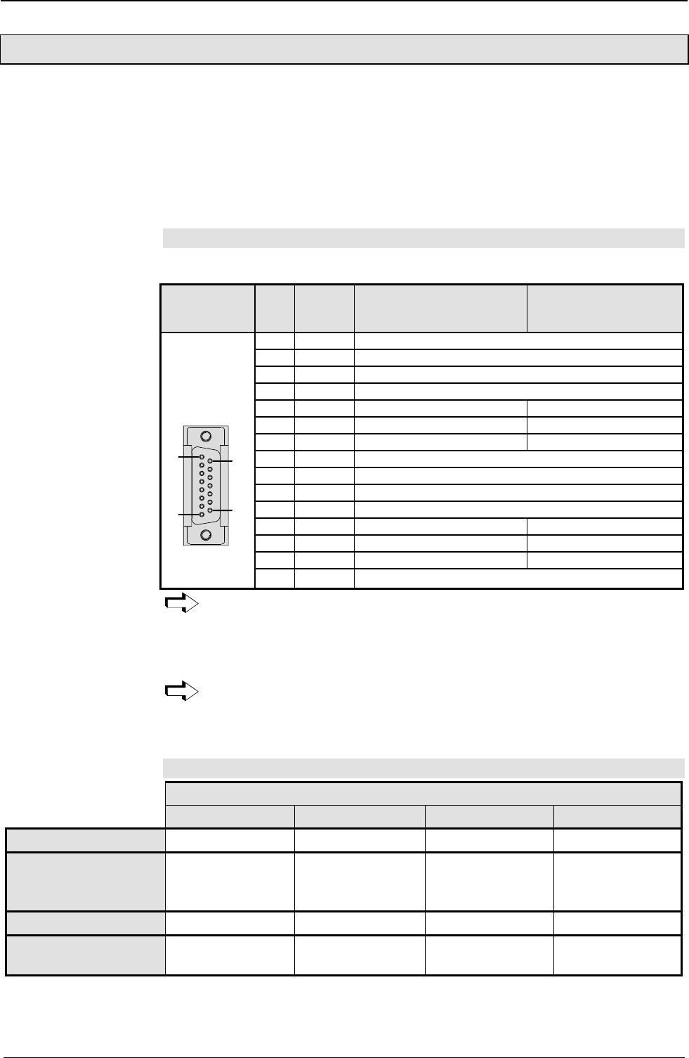
Start-up manual COMPAX-M / -S
X13: Encoder interfaces, ...
60
7.9.10 X13: Encoder interfaces, ...
The encoder interfaces are available as options for COMPAX (excluding COMPAX
1000SL). 2 channels are present; channel 1 can be equipped as the encoder input
and channel 2 as the encoder simulation. The necessary options are described on
Page 179.
With COMPAX 1000SL, an encoder interface is integrated in the standard unit.
This can be configured either as the encoder input or encoder simulation.
7.9.10.1 Encoder interfaces / analogue rpm specification for COMPAX
(not COMPAX 1000SL)
Connector X13 X13
Pin
Designat
ion:
Function with encoder input
or simulation
Function of channel 1 with
option I7 for COMPAX
XX6X or COMPAX XX70
1 Housing Screen terminal:
2 N2 Channel 2 zero impulse
3 B2 Channel 2 track B
4 2A Channel 2 track A
5 N1 Channel 1 zero impulse Enable
6 B1 Channel 1 track B +15V (<10mA)
7 1A Channel 1 track A Input (±10V)
8 +5V Output +5V
9 N2/ Channel 2 zero impuse inverted
10 B2/ Channel 2 track B inverted
11 A2/ Channel 2 track A inverted
12 N1/ Channel 1 zero impuse inverted Direction of rotation
13 B1/ Channel 1 track B inverted -15V (<10mA)
14 A1/ Channel 1 track A inverted Input (±10V)
15 pin
Sub-D socket
terminal strip
Screws
UNC4-40
1
8
9
15
15 GND Reference point
The "Incremental encoder" function is an option for which additional boards
are required . If the relevant options are available, the following applies:
Channel 1: encoder input. Channel 2: encoder emulation
We can provide the relevant cables and a bus distributor for wiring up the encoder
signals. Use these to implement various applications (see Page 179).
When working with COMPAX XX6X (electronic transmission) and COMPAX
XX70 (electronical curve control) variants, you can use option I7 via channel
1 to implement an analogue speed specification (see Page 186).
7.9.10.2 Area of application of process interfaces
Unit variants
COMPAX XX00 COMPAX XX30 COMPAX XX60 COMPAX XX70
Encoder emulation "
""
""
""
""
""
""
""
"
Encoder input ! External pos.
localization
! SPEED SYNC
! External position
localization
(actual value)
! Master position
(set value)
! Master position
(set value)
Analogue input ! SPEED SYNC -! Master speed ! Master speed
Cycle / direction input ! SPEED SYNC -! Master position
(set value)
! Master position
Encoder interfaces
for COMPAX
Encoder interfaces
for
COMPAX 1000SL
Assignment on
X13:
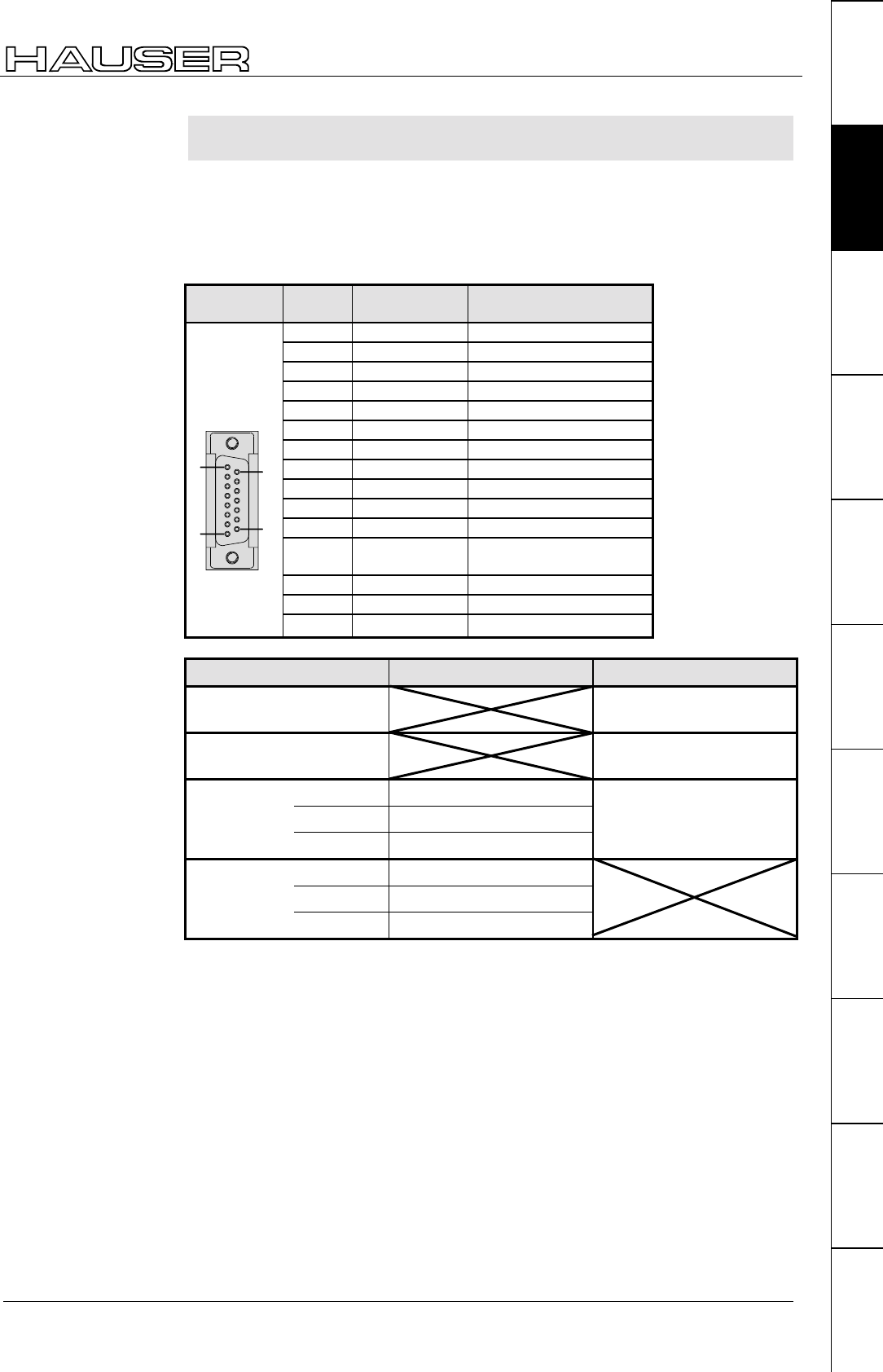
Interfaces
61
Unit
hardware
Connector
assignment / cable
Technical dataConfigurationPositioning and
control functions
Optimization
functions
InterfacesAccessories /
options
StatusParameterError list
7.9.10.3 Encoder interfaces / Analogue rpm specification / Step
direction input for COMPAX 1000SL
COMPAX 1000SL has an interface which can be configured either as encoder
input, encoder simulation, analogue input or step direction input. Encoder
simulation and analogue input can be used simultaneously.
This interface is a fixed part of COMPAX 1000SL. No other encoder interfaces are
possible. The connections are on connector X13:
Connector
X13
X13 Pin Designation: Function
1 Housing Screen terminal:
2nc
3nc
4 2A A2 (Analogue input)*
5 N1 Channel 1 zero impulse
6 B1 Channel 1 track B or direction
7 1A Channel 1 track A or step
8 +5V Output +5V
9nc
10 nc
11 A2/ A2/ (Analogue input)*
12 N1/ Channel 1 zero impuse
inverted
13 B1/ Channel 1 track B inverted
14 A1/ Channel 1 track A inverted
15 pin
Sub-D socket
terminal strip
Screws
UNC4-40
1
8
9
15
15 GND Reference point
Setting Outputs Inputs
P144 = 4 or 6
P146 = 0 Not possible! Encoder input
P144 = 5
P146 = 0 Not possible! Cycle / direction input
Encoder emulation
P146=8 512 Pulse/rev.
P144=7
P146 = 0 1024 Pulse/rev.
Analogue input ±
±±
± 10V*
Encoder emulation
P146 = 8 512 Pulse/rev.
P144 = 0
P146 = 0 1024 Pulse/rev.
switched off!
*The analogue input is only available with COMPAX XX60 and COMPAX XX70!
Encoder interface
/ Step direction
input for COMPAX
1000SL
Connector
assignment X13 for
COMPAX 1000SL
Process
interfaces
Configuration
options

Start-up manual COMPAX-M / -S
X13: Encoder interfaces, ...
62
P144 P146 Setting
= 4/6 = 0 Encoder input (without terminator) for individual connections, use
bus termination BUS06/01)
Cycle input O1 – O1/= 5 = 0 Cycle / direction input11
Counter cycle signal
(RS485/422)
Direction input B1 – B1/
= 0 = 0 Encoder simulation 1024 pulse / revolution without analogue
input
= 7 = 0 Encoder simulation 1024 pulse / revolution with analogue input
= 0 = 8 Encoder simulation 512 pulse / revolution without analogue
input
= 7 = 8 Encoder simulation 512 pulse / revolution with analogue input
= 7 = 0
= 7 = 8
Analogue input ±10V
Input on A2 and A2/
Resolution: 20mV
Rpm specification as with option I7,
however without direction of rotation
input*
The I7 function "direction of rotation" can be implemented in COMPAX 1000SL
by exchanging the differential inputs or by changing the rotation direction with
parameter P214 Bit 0.
The I7 function "enable" can be implemented via Input I11. Use P232=4 to assign
this function to Input I11 (COMPAX 1060/70SL only).
I11 ="1": Release analogue input
I11="0": Digital input value = 0 (input is set drift-free to 0)
1. Direct encoder – COMPAX 1000SL connection
Cable: GBK11 Bus terminal: BUS06/01 (the bus terminal is allocated to X13 as
adapter)
2. Direct COMPAX (simulation) – COMPAX 1000SL (input) connection
Cable: SSK7
3. Direct COMPAX 1000SL (simulation) – COMPAX (including COMPAX 1060SL
or COMPAX 1070L) connection (input); Cable: SSK17
4. An encoder distributor (EAM4/01) is used for the integration of COMPAX
1000SL into an encoder bus consisting of several COMPAX, as described in the
COMPAX User Guide.
It should be noted that COMPAX 1000SL always uses channel 1 (encoder input
and simulation).
11 The operation mode is also configured via the parameters P143 and P98.
These have the following significance:
P98 = Reference dimension P143 = 4
ensiondimReferenceperImpulses
Example: Reference dimension = 100mm
10 000 input pulses should give a movement of 100mm
P143=10 000/4 = 2500
Configuring the
process
interfaces
* function analogue
input
Applications with
COMPAX 1000SL
and encoder
(see page 179)
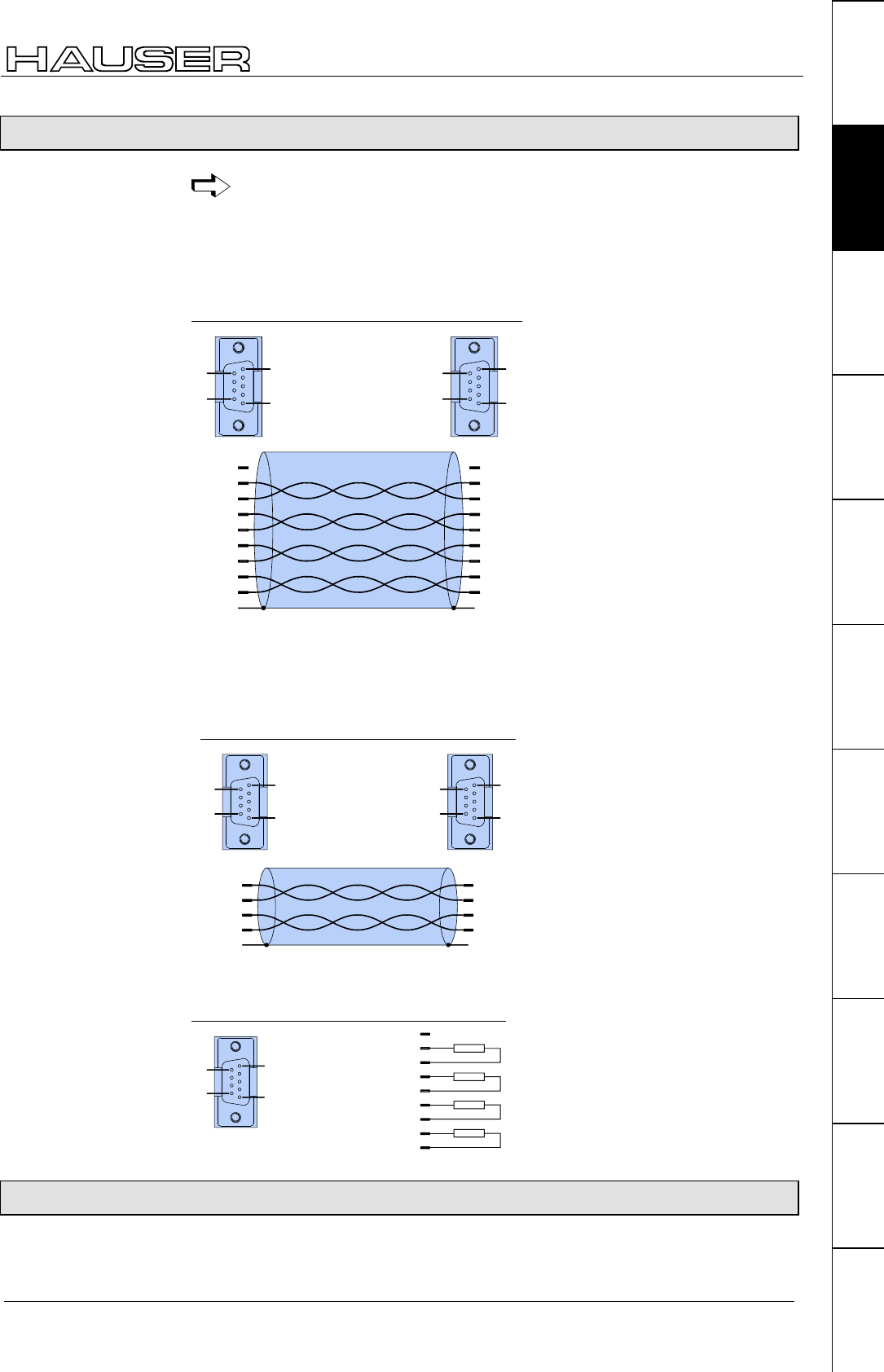
Interfaces
63
Unit
hardware
Connector
assignment / cable
Technical dataConfigurationPositioning and
control functions
Optimization
functions
InterfacesAccessories /
options
StatusParameterError list
7.9.11 HEDA interface (option A1/A4)
The HEDA interface is available for COMPAX XX00, COMPAX XX60 and
COMPAX XX70.
HEDA option A4: for COMPAX 1000SL
HEDA option A1: for all other COMPAX
IPM - COMPAX and COMPAX - COMPAX
housing
4 x 2 x 0.25mm + shield
2
housing
D-pin 9-way
D-plug shell 9-way
1
5
6
9
1
5
6
9
RxC 2
RxC/ 6
RxD 4
RxD/ 8
TxC 3
TxC/ 7
TxD 5
TxD/ 9
2 RxC
6 RxC/
4 RxD
8 RxD/
3 TxC
7 TxC/
5 TxD
9 TxD/
11
X15X14/PC
NC NC
data from Slave
clock from Slave
data from Master
clock from Master
SSK14 must not be used on a COMPAX which is configured as a master
(P243=1).
Cables for COMPAX master and COMPAX slave coupling:
housing
2 x 2 x 0.25mm + shield
2
1
5
6
9
1
5
6
9
TxC 3
TxC/ 7
TxD 5
TxD/ 9
housing
D-pin 9-way
D-plug shell 9-way
Slave: X14Master: X15
2 RxC
6 RxC/
4 RxD
8 RxD/
The last unit on the HEDA has a terminating connector (BUS2/01).
BUS 2/01
1
5
6
9
X15
RxC 2
RxC/ 6
RxD 4
RxD/ 8
TxC 3
TxC/ 7
TxD 5
TxD/ 9
1
NC 150Ω
150Ω
D-pin socket 9-way
D-plug shell 9-way
150Ω
150Ω
7.9.12 Bus connection
Special operating instructions are available for the bus systems.
Cable plan
SSK14/..:
Cable plan
SSK15/..
Terminating
connector
(BUS2/01).
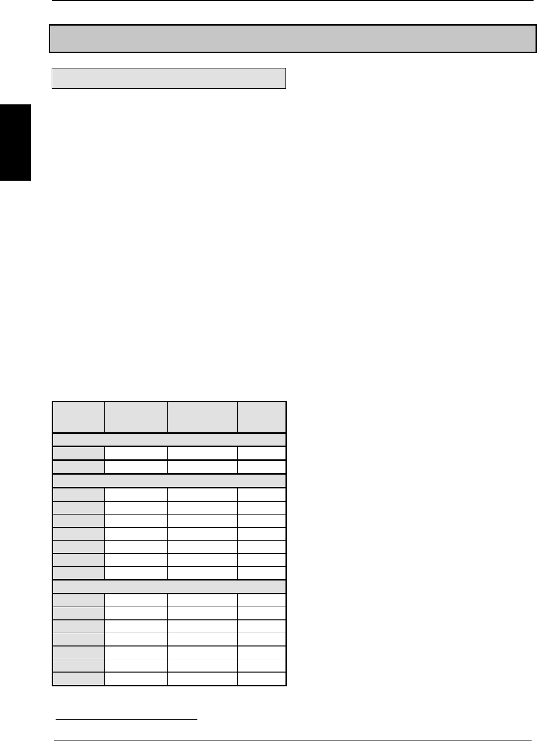
Start-up manual COMPAX-M / -S
64
Technical data
7.10 Technical data
Power characteristics
Functional capability
• Position, speed and current controller.
• IGBT final stage protected from short circuits and
ground/earth faults.
• Digital positioning controller.
• Motion controller.
Supported motors/resolvers
• Sine-commuted synchronous motors up to a max.
speed of 9000 rpm.
• Asynchronous motors.
• Supported resolvers:
• Litton:JSSBH-15-E-5
JSSBH-21-P4
RE-21-1-A05
RE-15-1-B04
• Tamagawa: 2018N321 E64
• Siemens: 23401-T2509-C202
• SinCos support (Stegmann).
• 3-phase synchronous linear motors12
• Sine-cosine linear encoder (1Vss) or TTL
(RS422)
• Digital Hall sensor commutation (5V).
Output data for individual units
Unit
COMPAX .
Nom.cur-
rent [Aeff] Peak current
[Aeff] <5s Power
[kVA]
with mains supply: 230V AC
10XXSL 2.5 5.0 1.0
25XXS 6.3 12.6 2.5
at mains supply: 400V AC
45XXS 6.5 13.0 4.5
85XXS 12.5 25.0 8.6
P1XXM 5.5 8.5 3.8
02XXM 6.5 8.5 4.5
05XXM 11.5 17.0 8.0
15XXM 25.0 50.0 17.0
35XXM 50.0 100.0 35.0
with mains supply: 460V AC
45XXS 5.4 13.0 4.5
85XXS 10.5 25.0 8.6
P1XXM 4.5 8.5 3.8
02XXM 5.4 8.5 4.5
05XXM 9.6 17.0 8.0
15XXM 21.0 50.0 17.0
35XXM 42.0 100.0 35.0
12 Reduced nominal data apply for linear motors; see Page 177.
CE conformity
• EMC immunity/emissions as per EN61800-3.
• Safety: VDE 0160/EN 50178.
Supply voltage (limit values)
COMPAX-M (NMD)
• 3 * 80V AC - 3 * 500V AC; 45-65Hz.
COMPAX 35XXM
• 3 * 250V - 3 * 500V AC; 45 - 65 Hz.
COMPAX 25XXS
• 3 * 80V AC - 3 * 250V AC; 45 - 65 Hz
1 * 100V AC-1 * 250V AC; 45-65Hz
COMPAX 10XXSL
• 1 * 100V AC-1 * 250V AC; 45-65Hz
COMPAX 45XXS/85XXS
• 3 * 80V AC - 3 * 500V AC; 45-65Hz.
Mains supply fuse protection
K circuit breaker or similar Neozed fusible cut-out.
• NMD (COMPAX-M)
NMD10: 16A (K circuit breaker: 20A) NMD20:
35A
• COMPAX 35XXM: 62A
• COMPAX 25XXS: 1x230V AC: 16A
3 * 230V AC: 10A
• COMPAX 10XXSL: 16A
• COMPAX 45XXS/85XXS: 16A
DC bus voltage
• 300V DC with 3(1) * 230V AC.
• 560V DC of 3 * 400V AC supply.
• 650V DC with 3 * 460V AC.
Output voltage to motor
Ignoring power losses, motor output rating is the
maximum motor output voltage of the AC supply
voltage available
Braking operation
• Storable energy
• NMD10/20: 1100µF / 173Ws
• CPMPAX 35XXM:3450µ / 542Ws
• COMPAX 25XXS: 1000µF/27Ws
• COMPAX 45XXS: 330µF/52Ws
• COMPAX 85XXS: 500µF/80Ws
• COMPAX 1000SL: 660µF/17Ws
• Ballast resistances (see Page 193)
Control voltage
• 24V DC ±10%, Ripple <1VSS
Current required:
• 1.3A for COMPAX 35XXM.
• 1A for COMPAX 45XXS/85XXS.

Technical data
65
Unit
hardware
Connector
assignment / cable
Technical dataConfigurationPositioning and
control functions
Optimization
functions
InterfacesAccessories /
options
StatusParameterError list
• 0.8A for the other units (incl. NMD).
• Digital outputs, each 100 mA.
• If needed, for fan approx. 100 mA.
• For motor holding brake (0.35A-1.6A).
• If needed, absolute encoder: 0.3A.
Accuracy
• Positioning on the motor shaft:
Resolution: 16 bits (= 0.3 minutes of angle)
Absolute accuracy: +/-15 minutes of angle
Maximum power dissipation
• COMPAX 10XXSL:......................50W
• COMPAX P1XXM:.....................140W
• COMPAX 02XXM / NMD10/20: . 120W
• COMPAX 05/10/15XXM: ...........250W
• COMPAX 25XXS: ....................... 80W
• COMPAX 45XXS/85XXS:.......... 170W
• COMPAX 35XXM: .....................610W
Data record memory
250 data records, protected from power failure.
Data record functions
• Positioning commands, I/O instructions, program
commands:
ACCEL, SPEED, POSA, POSR, WAIT, GOTO,
GOSUB, IF, OUTPUT, REPEAT, RETURN, END,
WAIT START, GOTO EXT, GOSUB EXT, SPEED
SYNC, OUTPUT A0, GOTO, POSR SPEED,
POSR OUTPUT , +, -, *, /.
Target value generator
• Ramps: linear, quadr., smooth; 10ms...60s.
• Travel specified in increments, mm, inch or
variable using a scaling factor.
Monitoring functions
• Mains power/auxiliary control voltage.
• Motor and final stage temperature/blocking
protection.
• Tracking error monitoring.
• Ready contact: 0.5A; 60V; 30W.
Ambient conditions
• Temperature range: 0...45°C.
• Max. relative air humidity as per DIN 40040 class
F (≤75%); no condensation.
Interfaces
Control inputs: 16 (8 for COMPAX 1000SL)
• 24V DC, 10 kOhm (see ex page 52).
Control outputs: 16 (8 for COMPAX 1000SL)
• active HIGH, short circuit protected; 24V (see ex
page 52).
RS 232
• 9600 baud or 4800 baud
(for COMPAX 1000SL, fixed at 9600 baud).
• Length of words 8 bits, 1 start bit, 1 stop bit.
• Software handshake XON, XOFF.
Programmable controller data interface
(excluding COMPAX 1000SL)
• via 5 binary inputs and outputs.
Encoder interface (option; standard for
COMPAX 1000SL)
• Encoder emulation: 512 or 1024 counts/rev
• Encoder input: RS422 interface; supply: 5V 120-
10000 lines/rev
COMPAX 1000SL signal interfaces
(optional)
• Encoder emulation or
• encoder input or
• step/direction input or
• analogue input ± 10V
Absolute value sensor interface (option A1)
(excluding COMPAX 1000SL)
• Supply voltage: 24V+/-10%.
• Sensing code: grey code, single step.
• Direction of counting: in clockwise direction when
looking at the shaft: rising.
• Data interface: RS422 /24 bit data format (start:
MSB). • Cycle frequency: 100 kHz.
SinCos
(option S1/S2/S3)
• High-resolution encoder instead of resolver.
• Single-turn or multi-turn (absolute value over 4096
motor revolutions).
• Option S2 with multi-turn: absolute value sensor
with programmable transmission factor.
• Option S3 for linear motors.
HEDA: synchronous, serial real time
interface
Included in option A4 or option A1.
Bus connection: optional
dc-insulated bus connection.
RS485
• Max. 115k baud • 2 or 4 wire/RS485
Interbus S
• 2-conductor remote bus • 500 kBaud.
• max. 64 participants per ring.
Profibus
• 1.5 MBaud • Sinec L2-DP and FMS.
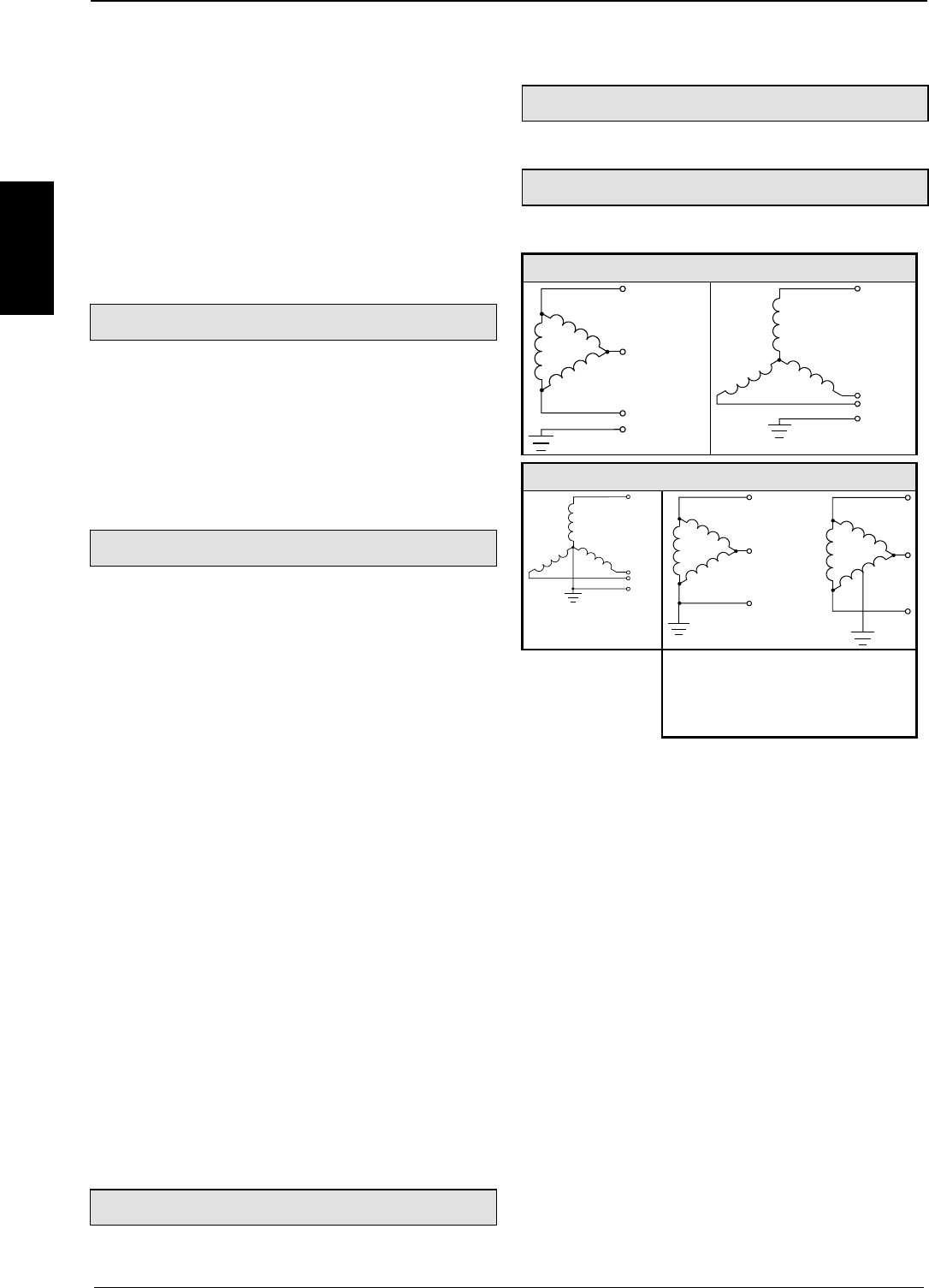
Start-up manual COMPAX-M / -S
66
Technical data
CS31
• COMPAX - ABB interface.
CANbus
• Up to 1.0 MBaud • Basic CAN.
• CAN protocol as per specification 1.2.
• Hardware as per ISO/DIS 11898
CANopen
• Protocol as per CiA DS 301.
• Profile CiA DS 402 for drives.
Operation
Parameter input/status request
• Via COMPAX hand-held terminal.
• Via RS232 and bus interface.
• Via the programmable controller data interface
(excluding COMPAX 1000SL).
• Status query also via the 3-digit LED display on
the front plate (excluding COMPAX 1000SL).
Housing
Housing
• Fully-enclosed metal housing.
• Insulation: VDE 0160/protection class IP20.
• IP54 on request.
Connections
• Motor, power bus, control inputs/outputs via
terminals.
• Sensor cables, interfaces via connectors.
Installation
• Wall mounting, suitable for installation in industrial
control cabinets.
Dimensions
• NMD/COMPAX-M: see Page 20.
• COMPAX 25XXS: see Page 33.
• COMPAX 10XXSL: see Page 43.
• COMPAX 45XXS/85XXS: see Page 36.
• Weights: COMPAX P1XXM: .............5.6 kg
COMPAX 10XXSL: ...........1.6 kg
COMPAX 25XXS: .............4.6 kg
COMPAX 45XXS/85XXS: ..6.5 kg
COMPAX 02XX:.................7.1 kg
COMPAX 05/15: ................7.8 kg
COMPAX 35XXM:............22.5 kg
NMD10:..............................7.6 kg
NMD20:..............................8.1 kg
Standard delivery
• COMPAX with User Guide.
• ServoManager.
Mains module
For technical data, see Page 23.
Permissible 3-phase mains
The units (COMPAX or NMD) can be operated on
all mains types1. Examples:
IT mains
TN mains
1When using Delta mains, note that CE
requirements (low voltage guideline)
are no longer met when the voltage
between a phase and earth >300V AC
(isolated measurement voltage).
Leakage current
The leakage current (current on the mains PE) is mainly caused
by the capacitive resistance between the conductor and
screening of the motor cable. Additional leakage current occurs
when using a radio interference suppresser as the filter circuit is
connected to earth via the capacitors.
The size of the leakage current depends on the following factors:
! length of motor cable.
! cycle frequency.
! with or without radio interference suppresser.
! motor cable screened or not.
! motor earthed at site or not.
The leakage current is very important regarding safety when
handling and operating the unit.
Please note
The unit must be operated with an effective earth connection
which satisfies the appropriate specifications for high levels of
leakage current (>3.5 mA).
The Servo booster must not be operated with a fault current
circuit breaker due to the risk of higher levels of leakage current.
If an FI circuit breaker is installed, it must not interrupt the
current circuit despite the following conditions (e.g. from ABB
series F804):
! DC component in leakage current (3-phase rectifier bridge).
! Brief occurence of pulse-shaped leakage currents when
switching on.
! High levels of leakage current.

Overview:
67
Unit
hardware
Connector
assignment / cable
Technical dataConfigurationPositioning and
control functions
Optimization
functions
InterfacesAccessories /
options
StatusParameterError list
8. Operating Instructions
Compact Servo Controller
8.1 Overview:
The COMPAX digital positioning system has been
designed for multi-axis applications in handling and
automation technology. COMPAX contains all the
functions required for a compact positioning system.
These functions are:
! digital inputs and outputs (PLC interface)
! a serial interface (RS232)
! a data record memory
! an integrated IGBT final stage.
You will need auxiliary equiment (PC, hand-held
terminal) to configure and program COMPAX.
COMPAX is very flexible and offers all the advantages
of digital control technology thanks to its completely
digital design which encompasses positioning, speed
and current control. The main features are:
! controller parameters which can be reproduced and
are drift-free
! simple copying of set values
! no offset problems
! the implementation of efficient, flexible and adaptable
setpoint generation.
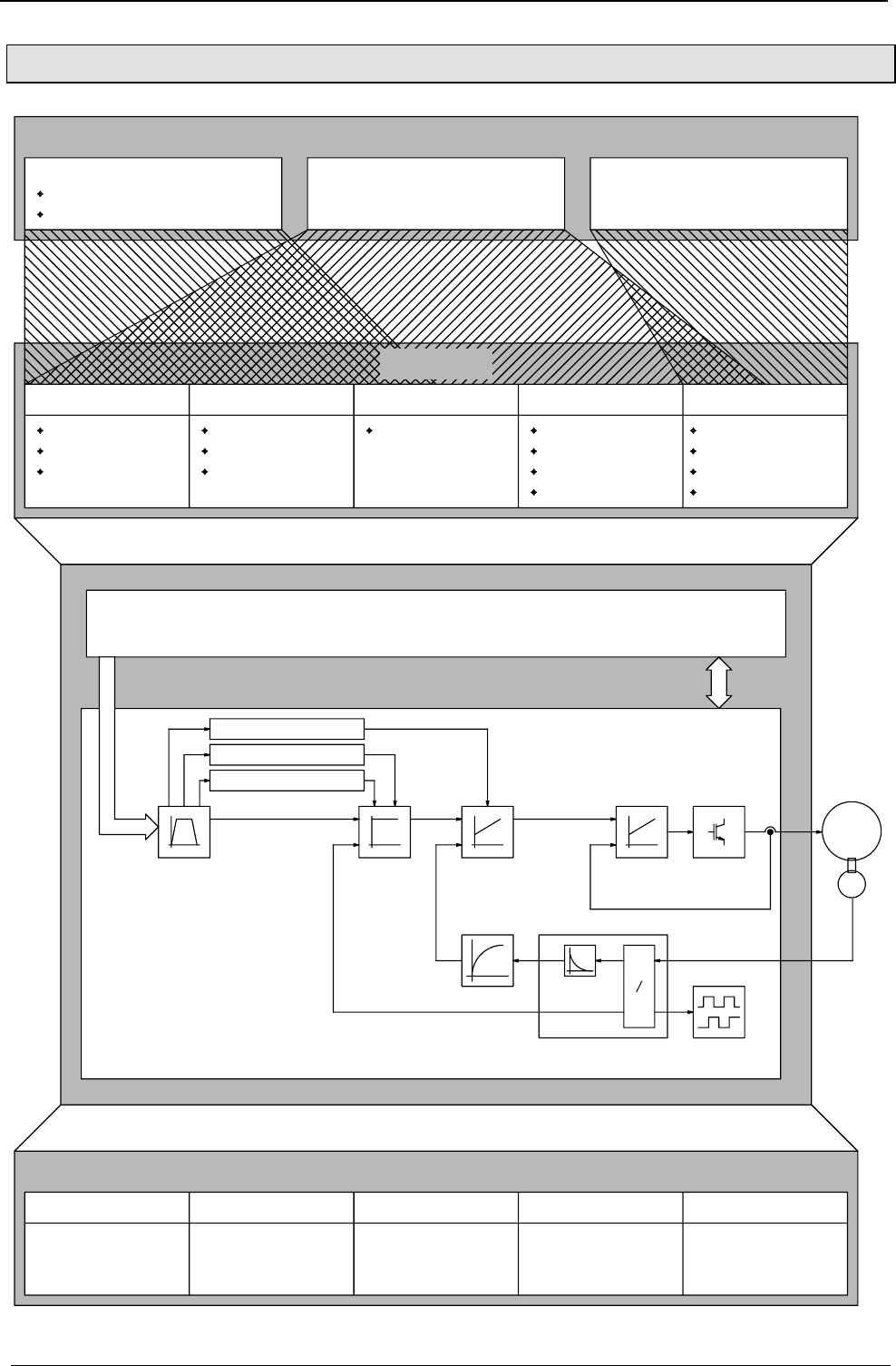
Operating Instructions COMPAX-M / -S
68
8.1.1 Block structure of the basic unit (not applicable for COMPAX 1000SL)
PLC data interface
Query the most important status values
Setting the most important parameters
RS232 / RS485 Bus-Systems
for connection of PLC, IPC, PC
or general. control unit /e.g.:
COMTAC from Hauser
16 Binary inputs and outputs
Status queries
Actual values
Diagnostic values
Setting parameters
Configuration
Optimization
General settings
Direct commands
ACCEL, SPEED
POSA, POSA HOME,
POSR, OUTPUT,
GOTO, ...
Programming
250 lines
Positioning commands
I/O instructions
Program flow commands
Controlling
manual+, manual-
Start, Stop, Break
Machine zero, real zero
Teach real zero, program line
Device IDs
Override input
Externally controlled
Absolute encoder Encoder input
Synchronization
to external
speeds and position
Encoder emulation
Output of
actual speed and
D/A monitor
reference drives
not required
position
2 analogue outputs for
internal values
(rotational speed, current, etc.)
Program memory / parameter memory
Travel commands Settings,
data
R
Rotational speed
controller
Position
controller
Setpoint
generator Current
controller Output stage
RD
Rotational speed filter
acceleration feed forward
Rotational speed and
position generation Encoder
simulation
current feed forward
speed feed forward
Interfaces for data and status
Functions
Interfaces for signals
System controller
Servo control
Motor
speed reduction

Overview:
Block structure of the basic unit (not applicable for COMPAX 1000SL)
69
Unit
hardware
Connector
assignment / cable
Technical dataConfigurationPositioning and
control functions
Optimization
functions
InterfacesAccessories /
options
StatusParameterError list
Explanations for the block structure
Interfaces for data and status
The following commands are available via 5 binary inputs (I7...I11) and 5 binary
outputs (O7...O11):
POSA, POSR, SPEED, ACCEL, GOTO, VP, modifying parameters P1..P49,
querying status S1...S12. (Function not available with the COMPAX 1000SL)
All functions are available via RS232.
All functions are available via the bus interface (Interbus S, Profibus, CAN bus,
CANOpen, CS31 or RS485 (ASCII/binary with 2 or 4 wires). A description is
available as a separate item.
Inputs:
I1...I6: control functions or freely assignable.
I7...I16: freely assignable or programmable.
Outputs:
O1...O6: control outputs or freely assignable.
O7...O16: freely assignable or programmable.
The status can be queried via the PLC date interface, the bus interface and
partially via the front plate display.
Operating mode, units for travel data, motor types, ramp shapes, directions, drive
types, reference systems, ....
Via the uncoupled stiffness, damping and advance control parameters.
Replacement and specification values,
limitations,
control parameters.
Programming a sequential program with up to 250 data records.
Functions: manual mode, start, stop, break, teach functions ....
Messages no fault, no warning, machine zero has been approached, ready for
start, position reached, idle after stop or break.
Program control: external data record selection, analyzing binary inputs, setting
binary outputs, triggering positioning processes,... .
Function monitoring and co-ordination
Digital control with robust control loops. Automatic calculation from existing design
quantities.
PLC data interface
RS 232
Bus systems
Binary inputs and
outputs
Functions
Query status
Setting
parameters
Configuring
Optimizing
General settings
Programming data
records
Controlling
System controller
Control

Operating Instructions COMPAX-M / -S
Password protection
70
Analogue input (see Start-up manual) for continual reduction of the set speed.
This option supports an absolute value sensor attached to the motor; reference
travel is therefore no longer required after initialization has been executed once
(see Start-up manual and Accessories and options).
(Function not available with the COMPAX 1000SL)
Real time data channel
For implementing track and contour tasks using the HAUSER "IPM" interpolation
module for PC and IPC or
direct COMPAX - COMPAX coupling with one COMPAX as the master.
COMPAX can be synchronized to an external speed (and/or position, e.g. with the
"Electronic transmission" unit variant) via this input (see Start-up manual and
Accessories and options).
The actual position value can be made available to other units via this channel (see
Start-up manual and Accessories and options) .
An encoder bus can also be created. (see description in "Accessories and
options")
18 internal measuring and intermediate parameters are output as analogue voltage
(+/-10V) via two 8 bit channels (or optionally 12 bit channels).
8.1.2 Password protection
COMPAX contains password protection to prevent unwanted data manipulation.
Before you configure COMPAX or set your parameters, you must enable these
functions with a password. When the axis is at standstill, proceed as follows to
enable and block:
♦
transmit GOTO 302 to COMPAX
♦
switch the unit off
or
♦
transmit GOTO 270 to COMPAX.
All parameters, except P40-P49, are protected by password.
The COMPAX program is not protected by a password.
Conditions for password input :
♦
There must not be any programs running.
Interfaces for
signals
Override input
Absolute value
sensor (option)
HEDA (option)
Encoder input
Encoder simulation
D/A monitor
Deactivate
password
protection:
activate password
protection:
Protected
parameters
Note!
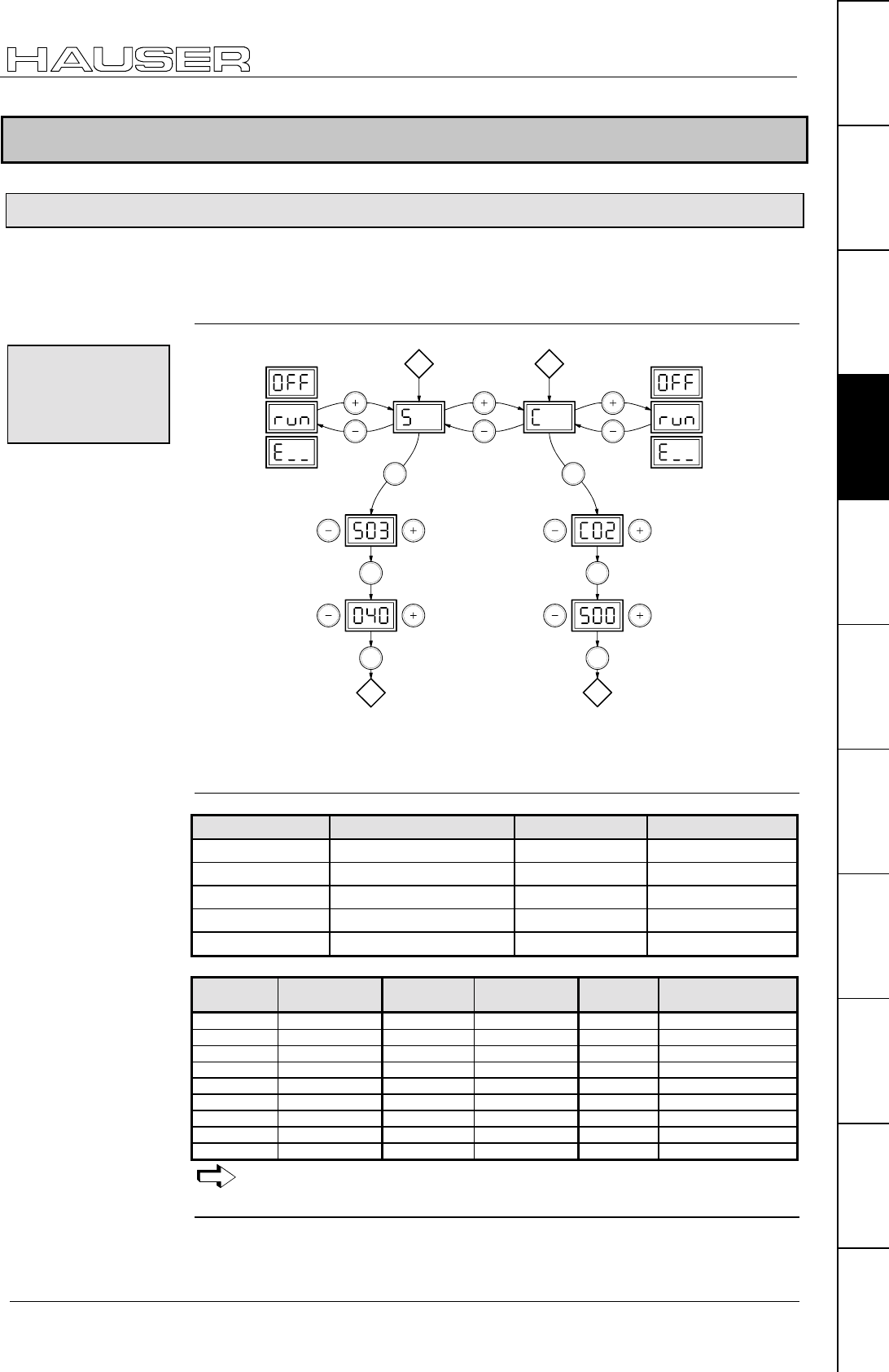
Configuration
Front plate operation (not available with COMPAX 1000SL)
71
Unit
hardware
Connector
assignment / cable
Technical dataConfigurationPositioning and
control functions
Optimization
functions
InterfacesAccessories /
options
StatusParameterError list
8.2 Configuration
8.2.1 Front plate operation (not available with COMPAX 1000SL)
Using the COMPAX front plate, you can query particular status values and perform
the most important bus settings. Also whenever an error occurs, COMPAX shows
the error number on the display.
call smaller
Status
number
without
function
decrease
value
increase
value
choose
Status
number
choose
number of
C-parameter
status
indicator
change
C-parameter
without
function
call higher
Status
number
call smaller
C-parameter
number
call higher
C-parameter
number
Enter Enter
Enter
A
Enter
B
AB
Enter Enter
choice of operation
modes
The following status values can be displayed via the front plate:
S03-S08, S11, S19-S26 (hexadecimal display), S27, S30, S31, S37-S39
(description of the status values: see Page 207).
The remaining status values can be queried via the interfaces.
C parameters COMPAX parameters Meaning Valid from
C01 P194 Address of unit Power on
C02 P195 Baud rate: Power on
C03 P196 Bus protocol Power on
C11 P250 HEDA address immediately
C04 - C10 reserved
Display
value Baud rate
[Baud] Display
value Baud rate
[Baud] Display
value Baud rate [Baud]
0 600 31 31 250 172 172 800
1 1200 38 38 400 187 187 500
2 2400 50 50 000 250 250 000
4 4800 57 57 600 345 345 600
9 9600 62 62 500 375 375 000
10 10 000 76 76 800 500 500 000
19 19 200 100 100 000 800 800 000
20 20 000 115 115 200 999 1 000 000
28 28 800 125 125 000
Please see operating instructions for the bus option used for the relevant
range of values and the precise setting options.
Once you have rectified the cause of the error, you can acknowledge the error by
pressing the "Enter" key.
Querying status
values and
modifying the
bus parameters.
Meaning of the
bus parameters:
Acknowledging
error messages
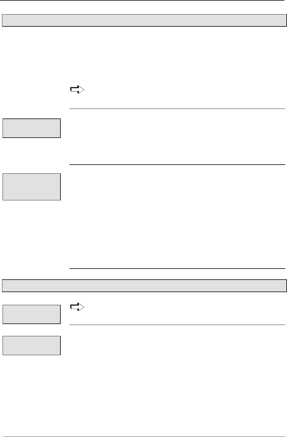
Operating Instructions COMPAX-M / -S
Configuration when supplied
72
8.2.2 Configuration when supplied
When supplied, COMPAX is not configured. Parameter P149 is set to "0":
P149="0": COMPAX is not configured and switches to OFF mode when switched
on (24V DC and operating voltage) (motor switched off). In addition to
this, when switched on, all parameters (apart from bus settings P194,
P195, P196 and P250) are set to their default values.
P149="1": COMPAX is configured and once switched on (24V DC and operating
voltage) tries to engage the motor.
If you are configuring using ServoManager, P149 is automatically set to "1"
once ServoManager has executed successful configuration.
To operate the COMPAX controller design concept, you must have a basic level of
technical control knowledge. COMPAX calculates the internal system and
controller parameters required using simple, application-specific values, which are
generally accessible.
A strong controller design obviates the need for tedious controller optimization.
This configuration provides you with a stable controller.
If the control process is unstable because COMPAX has been incorrectly
configured, you can switch on COMPAX so that the drive remains switched off
even with power on. To do this, when switching on COMPAX simultaneously press
the "-" key. The following will then happen:
♦
the drive is switched off.
♦
the digital outputs O1...O6 are set to "0".
♦
when the PLC data interface is switched on: O7=1, O8, O11=0
♦
the password protected functions are enabled.
Once you have correctly configured COMPAX or you have corrected the relevant
parameters, you can engage the drive and outputs again using the command
"OUTPUT O0 = 0".
(Function not available with the COMPAX 1000SL)
8.2.3 Configuration process
Before you configure COMPAX or modify the configuration, the drive must
be switched off e.g. using the command OUTPUT O0=1 or 2 (see Page 98).
The COMPAX configuration is carried out using parameters as follows:
♦
select operating mode.
♦
specify units for the travel data.
♦
select motor from the motor list or configure an external motor.
♦
select ramp shape.
♦
define direction.
♦
use the design data to specify the drive type.
♦
define the reference system.
Controller
design concept
Power on with
motor switched
off
Switching off
the drive
Modifying
parameters
Configuration
Safety instructions for initial start-up
73
Unit
hardware
Connector
assignment / cable
Technical dataConfigurationPositioning and
control functions
Optimization
functions
InterfacesAccessories /
options
StatusParameterError list
The ParameterEditor (part of the ServoManager) automatically guides you into the "Guided
configuration" menu through the input masks with the configuration settings.
From the next page, there is a clear description of the configuration process for
implementing new configurations. If this process is followed, you can specify all the
parameters required for your application.
In Chapter "Machine zero mode", you will find a description of options for machine
zero and limit switch configurations which deviate from the standard.
The configuration parameter are not accepted directly once they have been
modified. COMPAX will only accept the new parameters once the VC
commands (valid configuration) have been issued.
The ServoManager automatically sets the parameters as valid after
configuration!
Using the command OUTPUT O0=0.
Note that once a configuration has been set or modified, there
is a risk if some parameters have been incorrectly
programmed.
You must secure the displacement area of your system when
switching on the drive.
Please mind the limit values of the mechanical component!
Defiance of the limit values may lead to destruction of the
mechanical component!
8.2.4 Safety instructions for initial start-up
Risks from incorrect wiring!
In order to avoid the risks from incorrectly wired systems during initial start-up, use
the following settings for personal safety and protection of the mechanical system:
P15 = 10% (motor speed limited to 10% nominal value)
P16 = 100% (torque limited to 100% nominal value)
• The drive must remain at standstill after the system switch on.
• Execute a travel operation e.g. with POSR * or manually +/-.
If this travel operation is executed correctly, then P15 and P16 can be reset to their
original values.
The following faults may occur:
• The drive does not remain at standstill when switched on, or
• the drive runs out of control after the start command.
In both cases, either error E10 or error E54 is triggered.
If error E54 occurs, the drive is switched off.
A possible cause of the error is incorrect wiring in the motor or resolver systems.
Power on for
drive
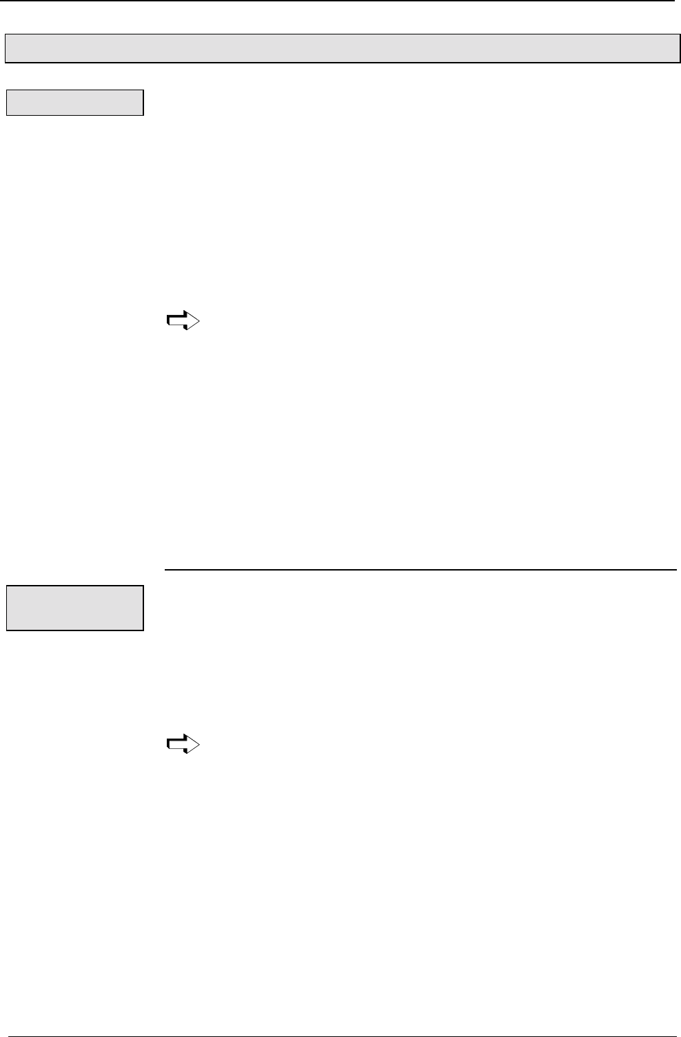
Operating Instructions COMPAX-M / -S
Configuration parameters
74
8.2.5 Configuration parameters
Parameter P93: valid from next move command.
P93 ="1"
Positioning processes refer to real zero.
To set the reference, use the "Find machine zero" function (Input I1="1" and I2="1",
see Page 148) once the system is switched on.
Various machine zero modes are described from Page 80.
P93 ="2"
Positioning processes always refer to the relevant start position.
The "Find machine zero" function is not necessary but possible.
Set P1 (real zero) = 0.
To avoid inaccuracies during conversions, use the "Increments" measurement
units in continuous mode (see below).
Operation with absolute value sensors is not permitted when working in
continuous mode.
P93 ="4":
In this operating mode, the drive controller operates as a speed controller, the
position controller is switched off. The following applies:
♦
Commands not permitted: POSA, POSR, POSR SPEED, POSR OUTPUT, POSA
HOME, ACCEL-.
♦
The SPEED command contains a prefix for the direction of rotation.
♦
Output O3 is not assigned;
O5 has the "Programmed nominal speed reached" function (see Page 120).
♦
The data record indicator is set to N001 using "Approach real zero".
♦
The "Find machine zero" function (I1&I2) is not assigned.
Parameter P90
P90 ="1"
P90 ="2"
P90 = "0": Accurate increment operation without conversion inaccuracies.
This measuring unit is only useful when using the "General drive" drive type
and especially in continuous mode. The levels of accuracy are not increased
when working with other drive types.
The "Travel per motor revolution" (P83) is specified in increments.
Meaning: P83 = 2n when n = 4, 5, 6, ...16
This corresponds to a resolution of 16 .... 65 536 increments per motor
revolution.
P83 influences the resolution and also the max. travel distance:
Operating mode
Normal mode:
Continuous
mode:
Speed controller
Unit for travel
data
mm
Inch
Increments
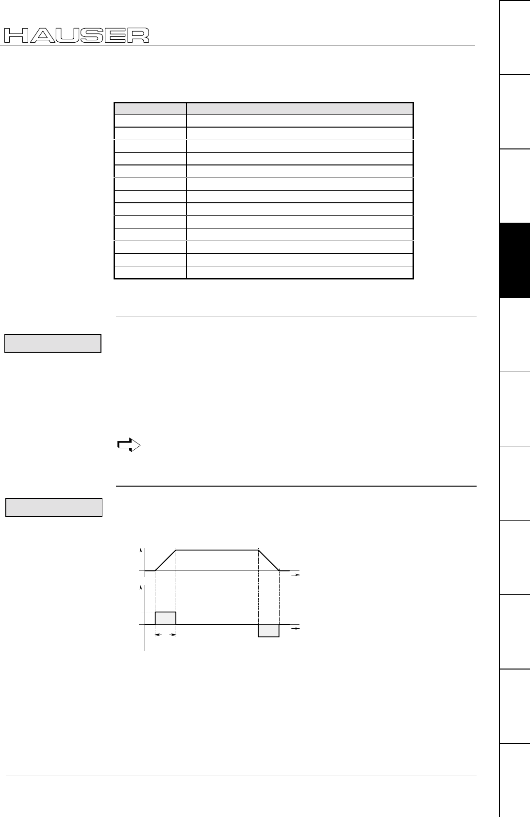
Configuration
Configuration parameters
75
Unit
hardware
Connector
assignment / cable
Technical dataConfigurationPositioning and
control functions
Optimization
functions
InterfacesAccessories /
options
StatusParameterError list
the max. travel distance is limited to ±4 million units. This corresponds to 61
revolutions at a maximum resolution of 65 536 increments per motor revolution.
The maximum travel distance can be increased by reducing P83. Meaning:
P83 Maximum travel in motor revolutions
16 ±250 000
32 ±125 000
64 ±62 500
128 ±31 250
256 ±15 625
512 ±7812
1024 ±3906
2048 ±1953
4096 ±976
8192 ±488
16 384 ±244
32 768 ±122
65 536 ±61
In continuous mode, this limitation applies to a single command.
In normal mode, this limit applies to the entire displacement area.
Parameter P100
The motor parameters are required for COMPAX motor-specific settings.
The motor parameters of the HAUSER motors recommended for COMPAX are
available in a list in ServoManager / ParameterEditor and can be selected from
there.
You can configure additional motors using the "External motor" function.
♦
Sine-commuted motors (sinusoidal EMC)
♦
Resolver / SinCos (see start-up manual under "Technical data" on Page 64).
The nominal currents of the motors and units must be adapted.
If you are using nominal currents which are smaller in relation to the unit
nominal current, current recording will be less accurate.
Parameter P94
P94 ="1"
Simplest, time-oriented function; not smooth
t
V
t
a , M
0
0
ta
1,0
Current requirement: 1 times
Motor type
Basic conditions
for external
motors:
Ramps
linear
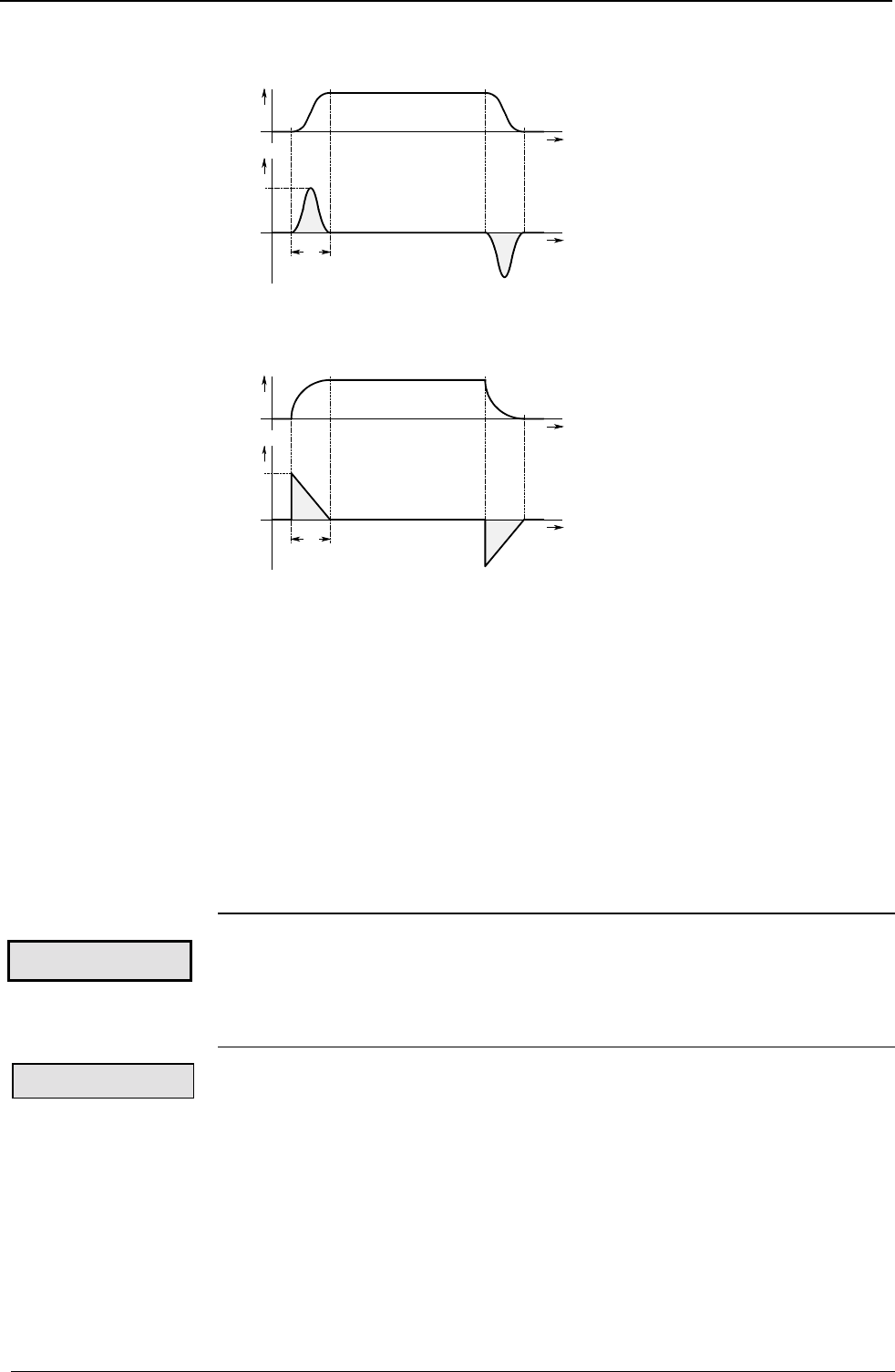
Operating Instructions COMPAX-M / -S
Configuration parameters
76
P94 ="2"
The mechanics are subject to minimum load when using the smooth function.
t
V
t
a , M
0
0
ta
1,9
Current required: 1.9 times
P94="3"
Gentle running in to the nominal value; overswings are prevented.
t
V
t
a , M
0
0
ta
2,0
Current required: 2 times
ta:Ramp time (can be set using the command "ACCEL", see Page 97)
v: Speed:
a: Acceleration.
M: acceleration torque
Transfer of P94
Modifications to P94 become effective from the next move command.
For the functions:
♦
stop after passing a limit switch and
♦
synchronous stop via I13 (see Page 151).
the ramp type only becomes valid with VC
Parameter P80: select drive type
Various data are required for additional configuration depending on the drive type
selected. This modifies the assignment of the parameters P81 - P85.
Continue configuration with the drive type selected.
P80=2:
Length of spindle
Range: 0 ... 5000mm
Diameter of spindle
Range: 8 ... 80mm
Pitch per spindle revolution.
Range: 1 ... 400mm
smooth
quadratic
Exception:
Drive type:
Spindle drive:
P81: length
P82: diameter
P83: Pitch
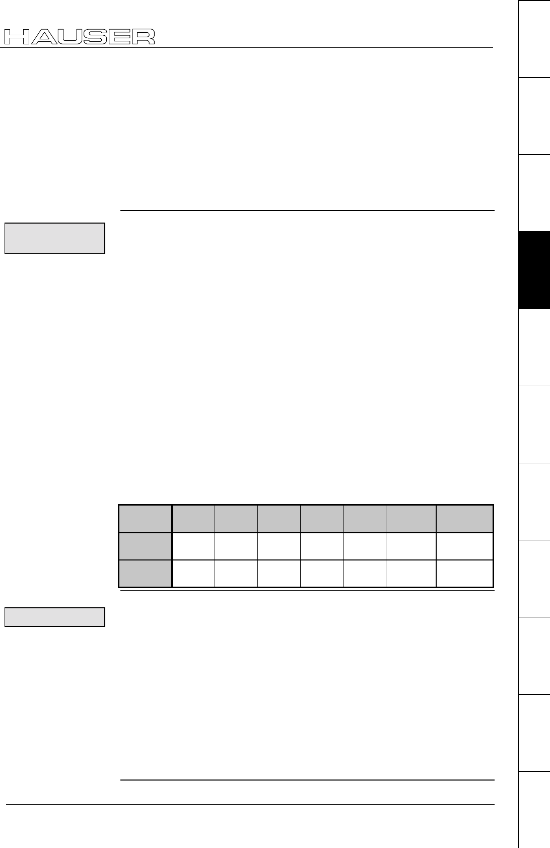
Configuration
Configuration parameters
77
Unit
hardware
Connector
assignment / cable
Technical dataConfigurationPositioning and
control functions
Optimization
functions
InterfacesAccessories /
options
StatusParameterError list
Motor / spindle ratio.
Range: 1 (1:1)...100 (100:1) ≡ motor: transmission
Moment of inertia of transmission and clutch referenced to the drive side.
Range: 0...200kgcm2
Minimum translational mass moved [kg].
Range: 0...P88
Maximum translational mass moved in [kg].
Range: 0...500kg
P80= "4" or "8"
Range: see tooth pitch
Distance between two teeth
The range of values for the number of teeth and tooth pitch is determined by the
pitch. Meaning: pitch = number of teeth * tooth pitch.
Range of pitch values: 1 ... 410 mm
Ratio from motor to rack-and-pinion/toothed belt.
Range: motor: transmission ≡ 1 (1:1)...100 (100:1)
Moment of inertia of transmission and clutch referenced to motor shaft.
Range: 0...200kgcm2
Minimum translational mass moved [kg]. Range: 0...P88
Maximum translational mass moved in [kg].
Range: 0...500kg
HLE80C HLE100C HLE150C HPLA80 HPLA120 HPLAB180 HPLAR180
rack+pinion
Teeth on
pinion (P82) 19 17 24 18 27 21 28
Tooth pitch
(P83) 10mm 10mm 10mm 10mm 10mm 20mm 10mm
P80=16:
Total minimum moment of inertia: motor, transmission and load referenced to the
motor shaft.
Range: 0...P82 [kgmm2]
Total maximum moment of inertia: motor, transmission and load referenced to the
motor shaft.
Range: P81...200 000kgmm2
Range: 10 ... 4 000 000µm
or 16 ... 65 536 increments.
P85: ratio
P84: moment of
inertia
P92: Minimum mass
P88: Maximum
mass
Rack+pinion/
toothed belts
P82: Number of
teeth on pinion
P83: tooth pitch
P85: ratio
P84: moment of
inertia
P92: minimum
mass
P88: maximum
mass
HLE / HPLA data for
the drive type:
"Toothed belt"
General drive
P81: Minimum
moment of inertia
P82: maximum
moment of inertia
P83: travel per
motor revolution

Operating Instructions COMPAX-M / -S
Configuration parameters
78
Parameter P213: direction of machine zero
(this describes the default setting, for more information see Page 80
Standard reference system: no end or reversing initiators; one machine zero
initiator at the end of the displacement area
The machine zero initiator must be attached so that it can only cleared in one
direction; i.e. attached to one side.
Use parameter P213 to inform COMPAX of the side on which the MZ13 (machine
zero) initiator is attached.
The machine zero initiator is approached with the motor turning clockwise (when
facing the motor shaft).
The machine zero initiator is approached with the motor turning anti-clockwise.
Set P215="0":
Actuate Hand+; the drive moves in the direction of the MZ initiator, then the
following applies: P213="0", if this is not the case, set P213="1".
The following basic setting applies for this standard reference system (≡ no
end or reversing initiators; one machine zero initiator at the end of the
displacement area): P212="1", P217="0", P216="0". You will find other
options for defining a reference system in the next chapter.
Specify the software end limits of the displacement area by using parameters P11
and P12. Each time a positioning command is issued, COMPAX checks whether
the target is within the travel distance. If this is not the case, error E25 is reported.
When working in continuous mode, these limits always apply for the current
positioning process.
Range: ±4 000 000 [units corresp. P90]
Range: ±4 000 000 [units corresp. P90]
Absolute positioning commands refer to RZ.
RZ is specified relative to machine zero.
P1 must be set to 0 in continuous mode .
Range: ±4 000 000 [units corresp. P90]
P215 establishes the positive direction of travel (positive end of displacement area)
referenced to the motor direction of rotation.
P215="0" the motor is turning clockwise when traveling in the positive direction
P215="1" the motor is turning anti-clockwise when traveling in the positive
direction
♦
Clockwise means when looking at the motor shaft.
Proceed with Hand+; the motor must move in the direction which is defined as
being the positive direction. If this is not the case, then P215 must be modified.
P215 has no influence on the setting of the machine zero direction (P213); if
it has the same mechanical design.
13 MZ: machine zero
Reference
system
P213="0":
P213="1":
Setting aid
Specifying
software end
limits
P11: maximum
position
P12: minimum
position
Specifying point
of real zero (RZ)
P1: point of real
zero
P215: direction
of rotation
Setting aid:
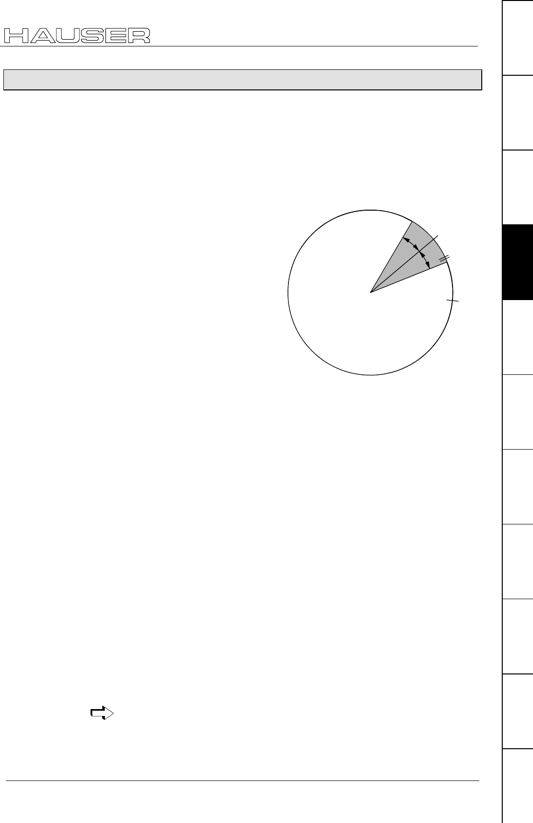
Configuration
Absolute value function with standard resolver
79
Unit
hardware
Connector
assignment / cable
Technical dataConfigurationPositioning and
control functions
Optimization
functions
InterfacesAccessories /
options
StatusParameterError list
8.2.6 Absolute value function with standard resolver
Absolute value function without special sensor for up to 4096 rpm
♦
Parameter P206=2 is used to activate the absolute value resolver.
♦
COMPAX reads the current actual position cyclically every 2ms and stores this
data alternatively onto 2 memory stores (Pos 2, Pos 3) protected against power
failure.
♦
The current imported position is shown in Status S12.
♦
After Power On, the last stored actual positions (Pos 2 and Pos 3) are read and
compared with each other and the current read resolver angle (Pos 1).
A3 is set, when
♦
the last saved actual position (Pos
2) lies within a definable window
(P161) around Pos 1,
and when
♦
Pos 2 and Pos 3 are less than
P161 from one another (to ensure
that the drive stops when
switched off).
Renewed referencing (find machine
zero) is not required.
S12 is copied after Power On,
enabling of the controller or after an
error in S1.
Pos 1
Pos 2
Pos 4
P
1
6
1
P
1
6
1
Pos 3
If the last saved actual position (Pos 4) lies outside a definable window (P161),
then A3 is not set, so a renewed referencing (find machine zero) is necessary.
in the switched off status, the motor or mechanics must not be moved. Ensure this
by using e.g. a motor brake or self-braking gearbox.
P161 gives the maximum permissible angle difference between the saved and the
current actual position when switching on.
Range: 1 ... 2047; default value 100; where 4096 = 1 motor revolution.
If P161 is exceeded, then a new reference is necessary (find machine zero).
♦
After error E42 (resolver/sensor error), referencing must always be implemented.
♦
The absolute value sensor function described above only functions with
resolvers.
♦
The absolute value function with resolvers is not supported by COMPAX XX30.
The value range of the absolute value S12 lies between –2048 and 2047.9999 (0
corresponds to the machine zero when P1=0). In addition, a value sign conversion
occurs (value jumps from the positive maximum value to the negative maximum
value; or vice versa), whereby at the next comparison S12→S1 an error of
precisely 4096 occurs.
Use a real zero P1 to shift the value range (around –P1).
Ex. 1: P1=-2000 value range S12: -48 ... 4047 rpm.
With knowledge of this relationship, it is possible to create a positive travel area of
maximum 0 ... 4096 by the following actions:
! Travel to center of total travel area
! PH with P1=-2048 and P212=10
! S1 = S12 = 2048 at this point
Travel from POSA 0 ... POSA 4095.9999 possible without value sign conversion.
Activated with
P206=2
Condition:
Maximum angle
difference P161:
Note
Value range S12
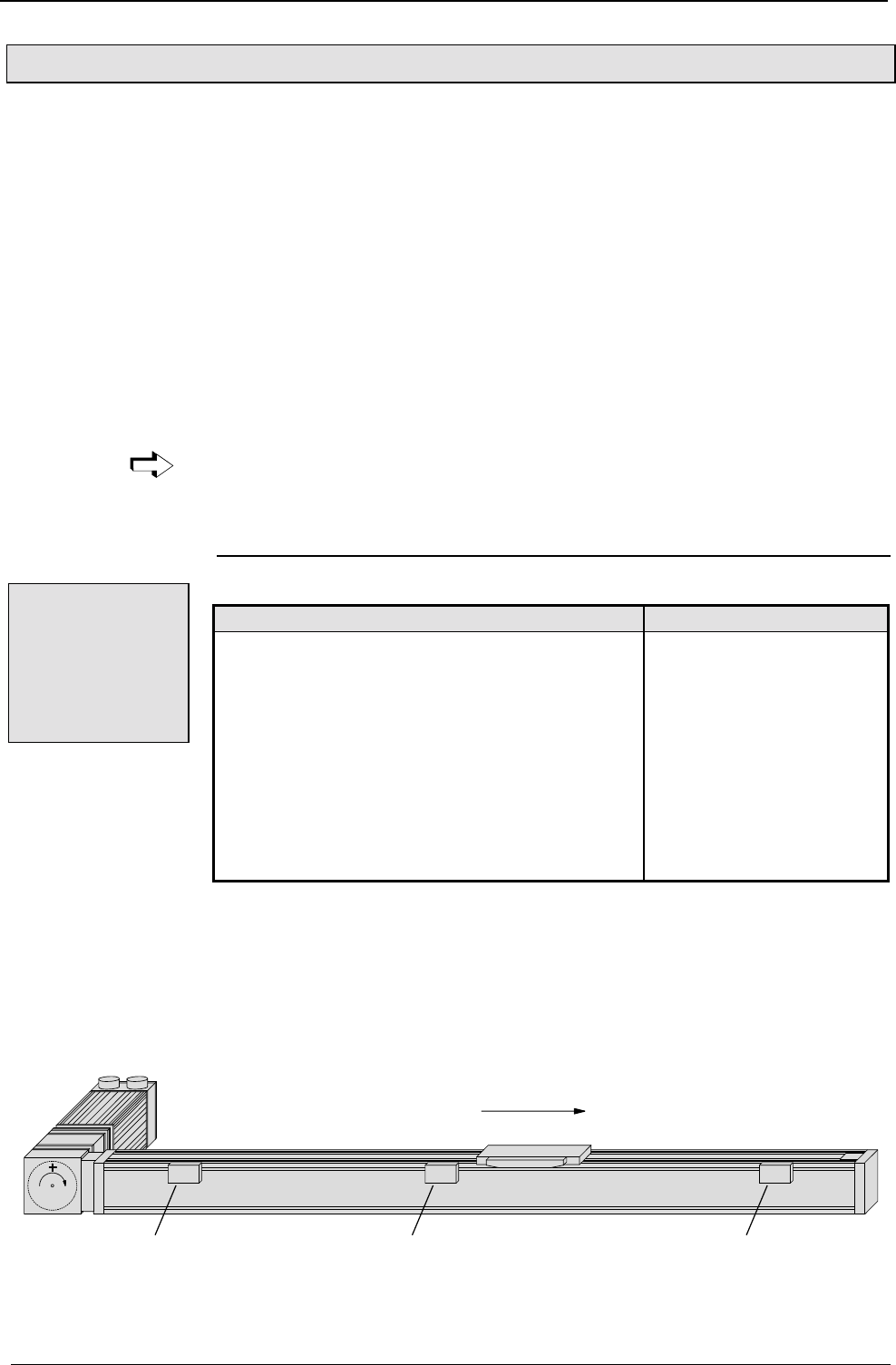
Operating Instructions COMPAX-M / -S
Machine zero mode
80
8.2.7 Machine zero mode
P212: setting the machine zero mode
="0": MZ equals external initiator rounded with resolver zero & machine zero travel
using 2 reversing initiators.
="1": MZ equals external initiator rounded with resolver zero.
="3": MZ equals external zero pulse*
="4": MZ equals external initiator rounded with the external zero pulse.*
="5": MZ equals resolver zero
="6": reserved
="7": MZ equals external initiator (without resolver zero).
="8": MZ equals a limit switch
="10": MZ teach
="11": Machine zero - initiator (without resolver zero) with 2 reversing initiators
P212 becomes valid immediately after a modification.
* P212=3 & P212=4 is only permitted for COMPAX XX00 and COMPAX XX30.
Function of the machine zero mode
P212 ="0"
Start search direction / initiator side Application
P213: defines the initiator flank of the machine zero
initiator that is being evaluated; i.e. the side
from which the initiator is approached.
P3: the prefix defines the start search direction.
P215: influences the start search direction during
find machine zero.
P29: shifts the actual machine zero in the direction
of the clockwise rotating motor.
P216: sets the limit switch position
(must also then be set if there are no
configured limit switches (P217=0)
Linear movements
P215="0": the motor rotates clockwise when traveling in the positive direction; i.e.
the positive end in the diagram is on the right-hand side.
P212="0": operating mode with reversing initiators; i.e. with 3 initiators.
P217="0": operating mode without end initiators. I1 and I2 act as reversing
initiators during "Find machine zero".
P216="0": the I1 initiator is started by the clockwise rotating motor.
P3 = positive (when P3 = negative, reverses start search direction)
E2 MN E1
gear doesn`t change
the direction
direction "clockwise rotating motor"
Overview:
Machine zero
equals external
initiator &
resolver zero / 2
reversing
initiators.
Example of a
reference system
definition
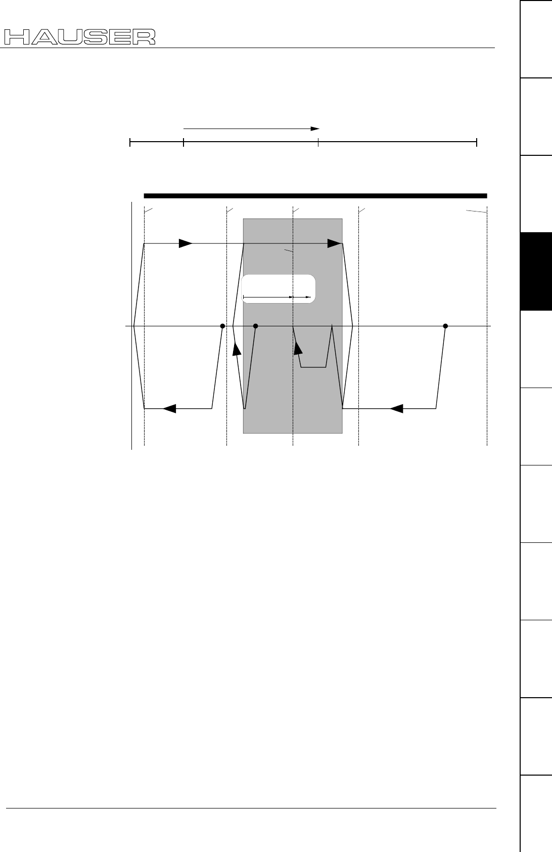
Configuration
Machine zero mode
81
Unit
hardware
Connector
assignment / cable
Technical dataConfigurationPositioning and
control functions
Optimization
functions
InterfacesAccessories /
options
StatusParameterError list
The position reference for positioning process is real zero; this can be freely
defined over the entire displacement area. Real zero is defined with reference to
machine zero.
machine zero
P12 real zero P11
value at P1 (real zero)
speed
distance
machine zero
switch
resolver
zero pulse
reverse initiator/
limit switch
reverse initiator/
limit switch
starting
position 1 starting
position 2
starting
position 3
E2 E1
resolver
zero pulse
resolver
zero pulse
actual machine
zero
shift machine
zero by P29
P29=90°...360°
P29=
0...90°
The speed used for find machine zero is specified by P3; the accelerating and
braking time by P7.
Real zero
Movement
process during
find machine
zero, depends on
start point:
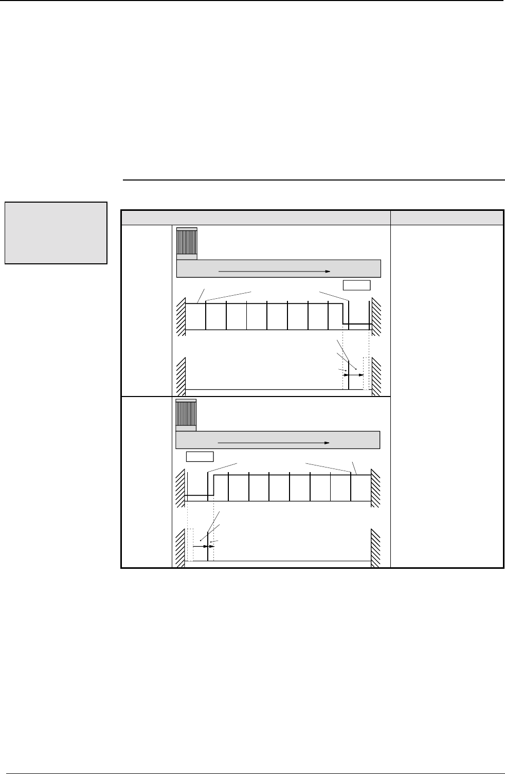
Operating Instructions COMPAX-M / -S
Machine zero mode
82
Additional machine zero modes
The machine zero modes described below are all used without reversing initiators.
The search direction and the evaluated initiator side are influenced as follows with
these machine zero modes:
P213: defines the start search direction and (if there is an initiator fitted) the initiator
flank of the machine zero initiator which is being evaluated; i.e. the side from
which the initiator is approached
P3: no influence in the start search direction during find machine zero.
P215: no influence on find machine zero.
P29: shifts the actual machine zero in the direction of the clockwise rotating motor
(see below).
P212 ="1"
Find machine zero Application
P213
="0
"
clockwise rotating motor
resolver zero pulse MN-Ini.
P29 = 270°- 360°
P29 = 0° - 270°
actual machine zero
signal of MZ
initiators
Standard machine
zero mode for linear
movements
P213="1"
clockwise rotating motor
resolver zero pulse
MN-Ini
actual machine zero
P29 = 100°- 360°
P29 = 0°-100°
signal of MZ initiators
Machine zero
equals external
initiator &
resolver zero
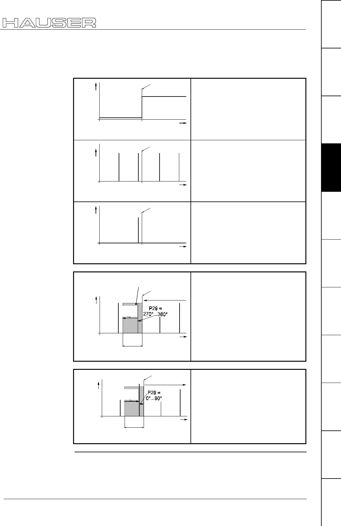
Configuration
Machine zero mode
83
Unit
hardware
Connector
assignment / cable
Technical dataConfigurationPositioning and
control functions
Optimization
functions
InterfacesAccessories /
options
StatusParameterError list
Explanation for shifting machine zero using P29, taking the example
of P212="1"
machine zero
initiator active machine zero
initiator disabled
0
signal
MZ-INI
mechanical
limit
position
initiator edge
The machine zero initiator (MZ-INI) is
low active
0
resolver
zero
pulse
machanical
limit
position
initiator edge
α0
The resolver zero pulse is a fixed
position of the rotor position
0
position
of the
actual MZ
mechanical
limit
position
α0
initiator edge
The actual machine zero (MZ) results
from the "AND" connection of the
machine zero initiator with the resolver
zero pulse
0
mechanical
limit
position
P29 =
0...270°
range within which the position of the
actual MZ can be shifted by P29
clockwise
rotating motor
360°
position of
actual MZ
initiator edge
α0
P29 shifts the actual machine zero in
the direction of the clockwise rotating
motor
0
mechanical
limit
position
P29 =
90...360°
clockwise
rotating motor
360°
position
of the
actual MZ
initiator edge
α0
P29 shifts the actual machine zero in
the direction of the clockwise rotating
motor
Shifting machine
zero
Example 1: α
αα
α0 = 90°;
clockwise rotating
motor in direction
of mechanical
limitation
Example 2: α
αα
α0 = 90°;
clockwise rotating
motor away from
the direction of the
mechanical
limitation travel
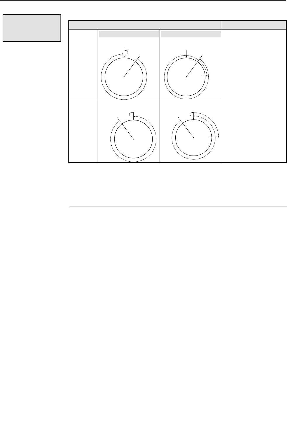
Operating Instructions COMPAX-M / -S
Machine zero mode
84
P212="3" (only permitted for COMPAX XX00 and COMPAX XX30!)
Find machine zero Application
P213="0" P29=0°
external
zero pulse command
"search MZ"
P29=90°
external
zero pulse command
"search MZ"
90°
General rotatory
movements
P213="1" external
zero pulse
command
"search MZ"
external
zero pulse
90°
command
"search MZ"
♦
External encoder; read via an encoder input module (I2, I4)
♦
Encoder input parametrized by: P144="6"
Specify P98 (travel per encoder revolution), P214 (encoder direction) and P143
(encoder pulse number).
Machine zero
equals external
zero pulse
Conditions for
this operating
mode:
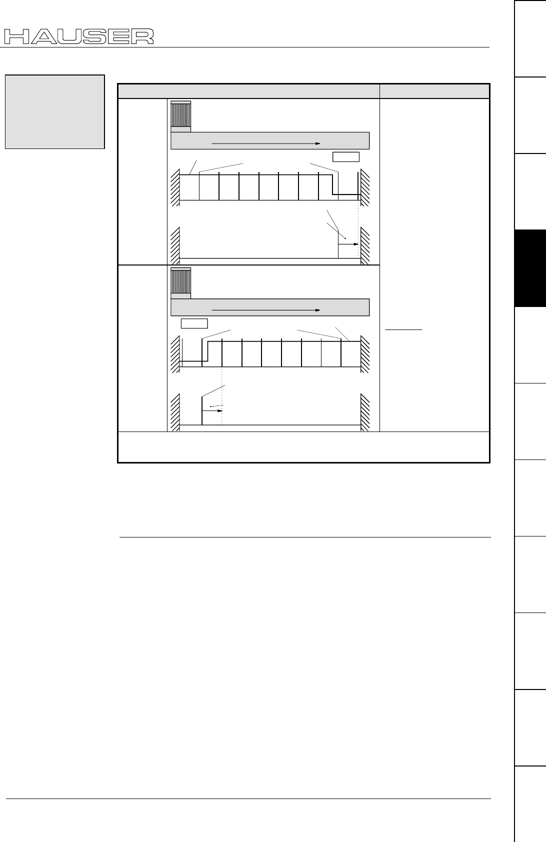
Configuration
Machine zero mode
85
Unit
hardware
Connector
assignment / cable
Technical dataConfigurationPositioning and
control functions
Optimization
functions
InterfacesAccessories /
options
StatusParameterError list
P212="4" (only permitted for COMPAX XX00 and COMPAX XX30!)
Find machine zero. Application
P213="0"
clockwising rotating motor
encoder zero pulse MN-Ini
P29 = 0°- 360°
position of the actual MZ
signal MZ-ini.
0° 360°
Linear and rotatory
movements.
If you have an encoder
on the load, with this
setting you obtain a
reproducible machine
zero response to any
transmission factor
which does not round
to whole digits (i.e. not
precisely displayable).
P213="1"
clockwise rotating motor
encoder zero pulse
MN-Ini
position of the actual MZ
P29 = 0°-360°
signal MZ-ini.
0° 360°
Example of an
transmission factor
that cannot be
displayed exactly:
teeth11
teeth17
Note!
If P75≠0 for this setting, external position localization is switched on.
♦
External encoder; read via an encoder input module (E2, E4)
♦
Encoder input parametrized by: P144="6"
Specify P98 (travel per encoder revolution), P214 (encoder direction) and P143
(encoder pulse number).
Machine zero
equals external
initiator &
external zero
pulse
Conditions for
this operating
mode:
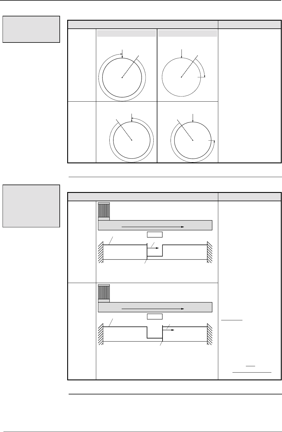
Operating Instructions COMPAX-M / -S
Machine zero mode
86
P212 ="5"
Find machine zero Application
P213="0" P29=0°
resolver
zero pulse command
"search MZ"
P29=90°
resolver
zero pulse command
"search MZ"
90°
General rotatory
movements.
This is a simple
method of
implementing machine
zero, especially if the
transmission runs at
high speeds.
P213="1" resolver
zero pulse
command
"search MZ"
resolver
MZ pulse
command
"search MZ"
90°
P212 ="7"
Find machine zero Application
P213="0"
clockwise rotating motor
MN-Ini
position of actual MZ
signal of MZ-ini.
P29 = 0° - 360°
0° 360°
Linear and rotatory
movements.
If you have an encoder
on the motor side, with
this setting you obtain
a reproducible
machine zero
response to any
transmission factor
which does not round
to whole digits (i.e. not
precisely displayable).
P213="1"
clockwise rotating motor
MN-Ini
position of actual MZ
signal MZ-ini.
P29 = 0° - 360°
0° 360°
Example of an
transmission factor
that cannot be
displayed exactly:
teeth11
teeth17
Accuracy: depends on
P3.
Accuracy in motor
revolutions:
=••
•
13
100 104
60 1000
ms PP
Machine zero
equals resolver
zero
Machine zero
equals external
initiator
(without
resolver zero)
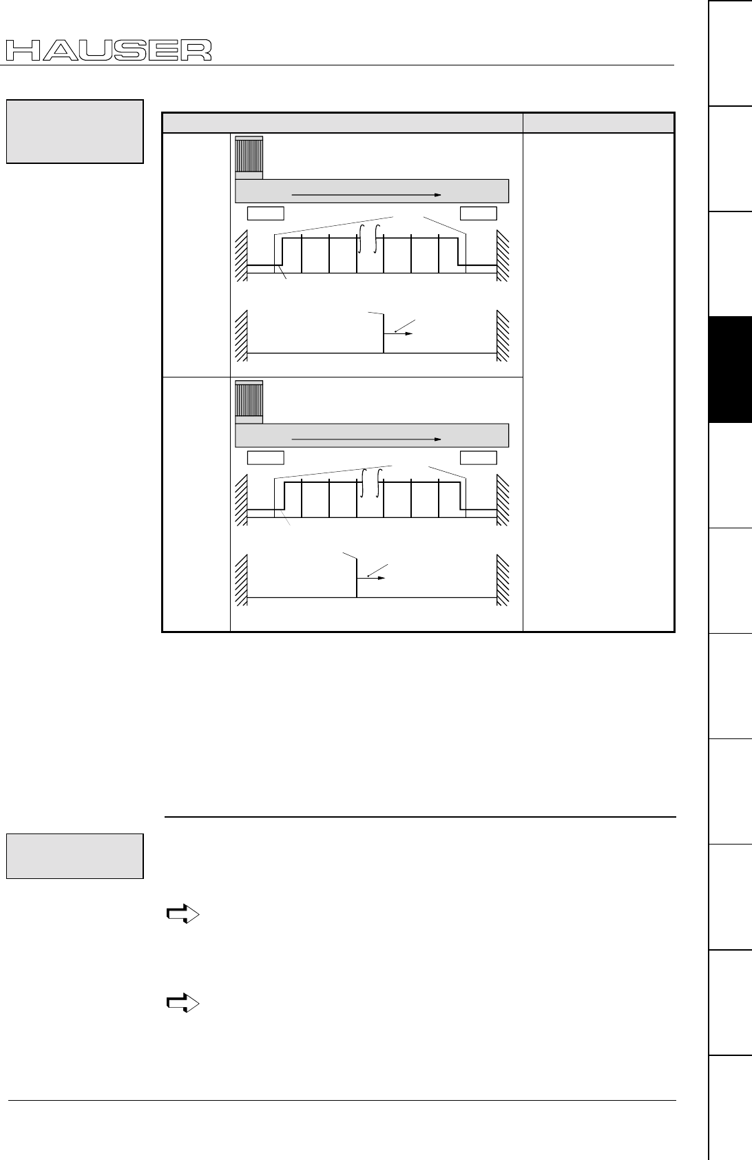
Configuration
Machine zero mode
87
Unit
hardware
Connector
assignment / cable
Technical dataConfigurationPositioning and
control functions
Optimization
functions
InterfacesAccessories /
options
StatusParameterError list
P212 ="8"
Find machine zero Application
P213="0"
clockwise rotating motor
E2
P29 = 0°- 360°
position of actual MZ
signal MZ-ini.
E1
0° 360°
...
resolver zero
pulse
Linear movements.
No need for a machine
zero initiator.
Function
Travels during "Find
machine zero":
♦
to the relevant limit
switch.
♦
back to the 3rd
resolver zero pulse.
The 3rd resolver zero
pulse is evaluated as
machine zero.
P213="1"
clockwise rotating motor
E2
P29 = 0°- 360°
position of actual MZ
signal MZ-ini.
E1
0° 360°
...
resolver zero
pulse
Supplement
With P202, the distance
between initiator and
machine zero can be
increased (e. g. for large
gear ratios). Meaning:
P202=0 or 3; function as
described.
With P202>3, the
distance of the machine
zero can be moved by
further resolver zero
pulses.
P202 unit:
Resolver zero pulses =
motor revolutions
P217 ="1"
P216 = set correctly.
In the above diagram: P216="1": (limit switch E1 is approached with anti-clockwise
rotating motor)
The input of the machine zero initiator (X17/7) must be wired up with the relevant
limit switch:
P213="0": X17/8 must be connected to X17/7.
P213="1": X17/9 must be connected to X17/7.
P212="10": Teach machine zero
When activated via the command "Find machine zero" (Input I1&I2 or
command "POSA Home"), the current position of the motor is defined
as the machine zero.
A machine zero initiator is not required with this method.
Via parameter P29, machine zero can be moved from the teached point by up to
one motor revolution. The drive then executes machine zero travel from the current
position by the angle P29 in a clockwise direction.
Range of values for P29: 0...360 degrees (other values are considered as 0).
If P29=0, machine zero travel is not implemented.
Machine zero
equals a limit
switch
Condition:
Wiring up:
Teach machine
zero

Operating Instructions COMPAX-M / -S
Machine zero mode
88
P212="11": Machine zero - initiator (without resolver zero) with 2
reversing initiators
Application: Applications with belt drives where the belts may skip during operation.
Machine zero -
initiator
(without
resolver zero)
with 2 reversing
initiators

Configuration
Limit switch operation
89
Unit
hardware
Connector
assignment / cable
Technical dataConfigurationPositioning and
control functions
Optimization
functions
InterfacesAccessories /
options
StatusParameterError list
8.2.8 Limit switch operation
P217 ="0" Operating mode without end initiators
P217 ="1" Operating mode with two end initiators
2 initiators are required.
The displacement area is limited by the initiators attached at both ends of it. When
one of the end initiators is activated, an error message appears, the drive is
decelerated using P10; this does not apply to the "Find machine zero" function.
Subsequently, the limit switches can be deactivated with Hand+ or Hand-.
When P212 = 0 (or = "2"), the initiators are used as reversing initiators during "Find
machine zero".
In other machine zero modes, the initiators can be switched to end initiators by
P217 via bit 0="1".
Bit 114 (P217) = 0: limit switches are not monitored during reference travel.
= 1: (P217= 3) limit switches are monitored during "Find machine
zero" (when P212<>0 and P212<>2).
The operating mode bit 1 (P217)=1 assumes that 3 initiators are connected. Here it
is not possible to use one of the two end initiators as a machine zero initiator.
Regardless of the search direction P213, both limit switches are monitored.
When one of the two limit switches is reached, COMPAX responds with an
emergency stop.
Then the following applies: move out of the danger zone using Hand+/-, then
acknowledge.
In such cases, the "MZ approached" output is not set.
Bit 2 (P217) = 0: function corresponding to Bit 0 and Bit 1.
= 1: (P217= 5) after activation of a limit switch, the drive is braked
with P10 (standard), however travel movements are still
possible afterwards using POSA and POSR.
The operating mode bit 1 (P217)=5 assumes that 3 initiators are connected. Here it
is not possible to use one of the two end initiators as a machine zero initiator.
Initiator I1 is assigned the direction of motor rotation using P216.
P216: ="0": initiator I1 is approached with the clockwise rotating motor.
P216: ="1": initiator I1 is approached with the anti-clockwise rotating motor.
Clockwise rotation defined when looking at the motor shaft.
Move to a limit switch using Hand+ (when P215="0"); an error message appears in
the COMPAX display:
♦
error 50: I1 has been activated; i.e. P216="0"
♦
error 51: I2 has been activated; i.e. P216="1"
This allocation only applies if P215="0"; if P215="1" the allocation is
reversed.
When operating with the reversing initiators, but no limit switches, an error
message will not appear. You then have two options:
14 Bit-counting begins with Bit 0.
Limit switch
monitoring
during the
reference travel
Response when the
limit switch is
reached:
Limit switch
monitoring
without locking
the movement
P216:
specifying the
limit switch
position
Setting aid:

Operating Instructions COMPAX-M / -S
Limit switch operation
90
♦
to set P216, switch on operation with limit switches (P216="1") or
♦
in status value S24, see bits 3 and 4 (from the left) to determine which initiator is
activated. Meaning:
Bit 3: I2 is activated, i.e. P216="1
Bit 4: I1 is activated, i.e. P216="0"

Configuration via PC using "ServoManager"
Installing ServoManager
91
Unit
hardware
Connector
assignment / cable
Technical dataConfigurationPositioning and
control functions
Optimization
functions
InterfacesAccessories /
options
StatusParameterError list
8.3 Configuration via PC using "ServoManager"
There is a separate manual describing how to work with ServoManager.
8.3.1 Installing ServoManager
Before installation, deactivate the following programs:
♦
any virus detection software.
♦
the Miro Pinboard in Miro graphic cards.
Information concerning these programs.
Following installation, the virus software can be reactivated.
Problems may also occur during program execution with Miro Pinboard.
Start the "Setup.exe" program on disk 1. The installation is a menu-guided process.
Following the installation, a Windows program group will appear containing the
ServoManager and the terminal.
8.3.2 Configuring COMPAX
♦
Create connection to COMPAX: cable SSK1 (see Page 59).
♦
Call up ServoManager.
♦
Create a new project (Menu: Project: New).
♦
Using the menu "Axis: Insert: From controller" to set up an axis which contains all
COMPAX settings (all parameters: including system parameters and data
records, curves are also available for COMPAX XX70).
♦
Use the menu "Servo-Tools: to switch to ParameterEditor.
♦
Call up menu "Configuration: Guided configuration".
All configuration parameters are queried one after another.
8.3.3 Individual configuration of synchronous motors
In addition to the motors contained in ServoManager / ParameterEditor, you can
configure almost all synchronous motors. The conditions required for the motors
and resolvers are listed in the start-up manual under "Technical data".
To modify motor parameters, the motor must be switched off (use OUTPUT O0=1
or press the "-" button on the front plate while switching on COMPAX).
You will find the data required for this on the HAUSER motor type plate.
Preparation
Installation
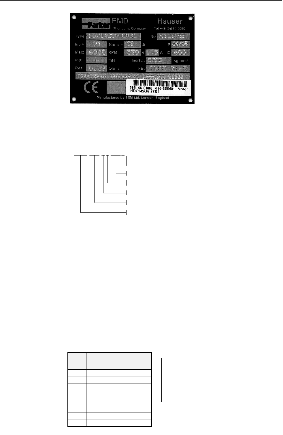
Operating Instructions COMPAX-M / -S
Individual configuration of synchronous motors
92
The following parameters can be read directly from the motor type plate :
♦
P101 number of motor terminals
♦
P102: EMC [V/1000 rpm]
These two values are included in the motor type description (type).
HDY xxx Ax-xxxS
S: sinusoida l E MF
T: trapezoidal EMF
EMF given in V per 1000 rpm
number of poles of motor
motor type: HDY,HJ or HBMR
motor length
flange size of motor
♦
P103: motor moment of inertia (inertia) [kgmm2]
♦
P109: stator inductivity (ind) [µH]
♦
P113: maximum mechanical speed (max)[rpm]
♦
P116: stator resistance (res) [Ω]
♦
P105: effective value of nominal current IN[mA]
HBMR motors: IN= 0.95 * I0
HDY motors: IN= 0.85 * I0
HBMR 55 and 70: IN = 0.85 * I0
♦
P106: nominal torque MZ
HBMR motors: MN= 0.92 * M0
HDY motors: MN= 0.82 * M0
HBMR 55 and 70: MN= 0.82 * M0
when I0= idle current
M0= idle torque
The other parameters are derived from the type plate data
Nominal motor speed for the HBMR motors
♦
P104: nominal motor speed [rpm]
EMC nN [min-1]
UZW=300V UZW=560V
32 5000
44 4000 5000
64 2600 5000
88 3500
130 2400
180 1700
260 1250
360 800
Motor type plate
Proceed as follows:
with
EMC: counter EMC
nN: nominal speed
UZW: intermediate circuit voltage
300V: with 230V AC
560V: with 3 * 400V AC
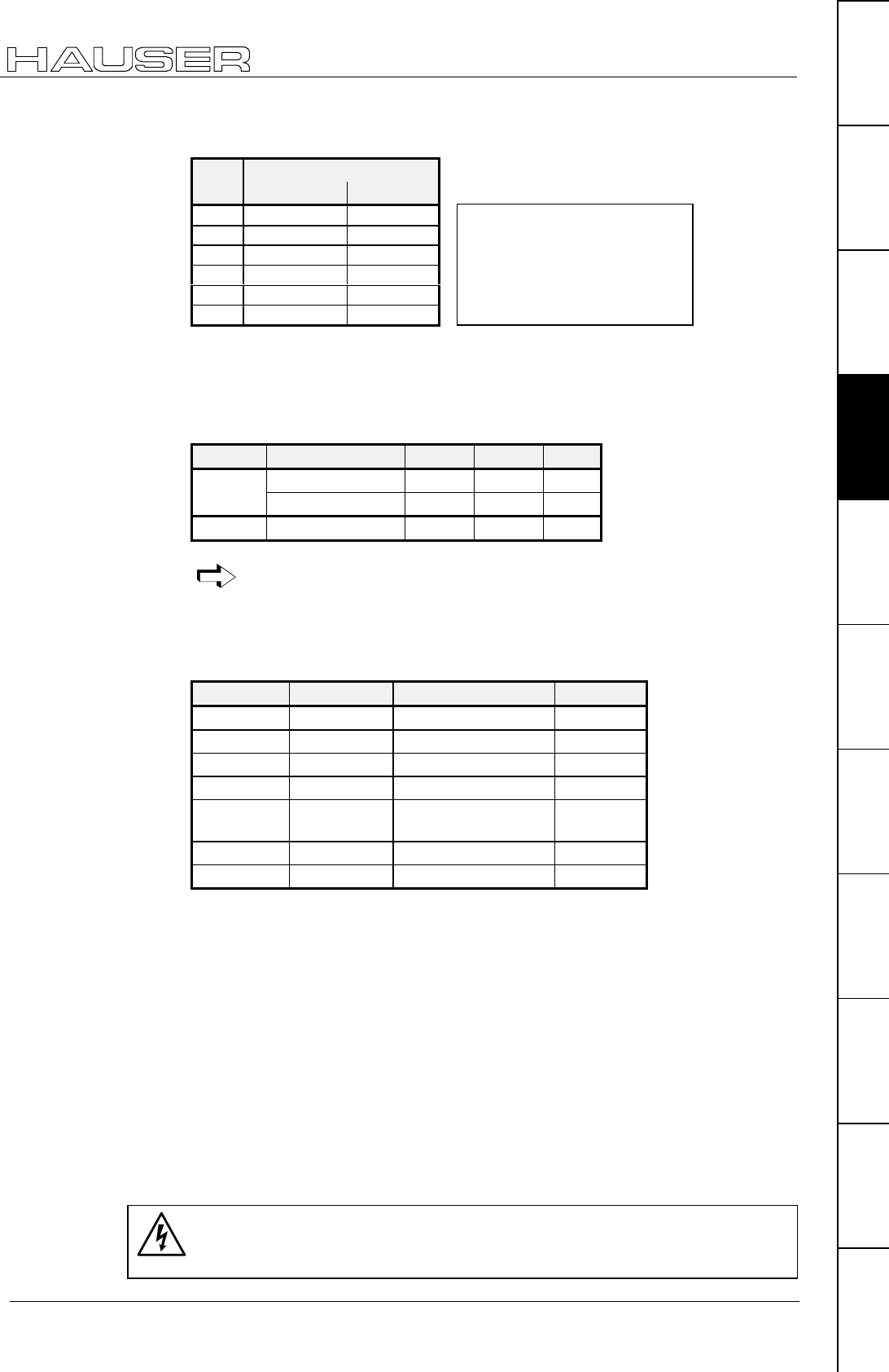
Configuration via PC using "ServoManager"
Individual configuration of synchronous motors
93
Unit
hardware
Connector
assignment / cable
Technical dataConfigurationPositioning and
control functions
Optimization
functions
InterfacesAccessories /
options
StatusParameterError list
Nominal motor speedfor HDY motors:
♦
P104: nominal motor speed [rpm]
EMC nN [min-1]
UZW=300V UZW=560V
32 5000
44 4400 5000
64 2800 5000
88 2000 3800
130 1400 2500
180 1800
Parameter for saturation characteristic curve:
♦
P119 start of saturation [%]
♦
P120: end of saturation [%]
♦
P121: minimum stator inductivity [%]
Flange size P119 P120 P121
HBMR <= 115 mm 100 280 40
>= 142 mm 70 240 40
HDY/ HJ 100 400 100
Saturation is switched off when P119 = P121 = 100% and P120 = 400%.
If the saturation is unknown, use the HDY values.
The additional parameters in the motor table should only be modified
under exceptional circumstances.
Default values of the HBMR and HDY motors:
Parameter Standard Meaning Unit
P107 300 Pulse current %
P108 3000 Pulse current time ms
P129 0 Resolver offset Degree
P130 "2" Resolver frequency
P131 "2" Resolver
amplification
P132 "2" Position sensor
P133 65 536 Sensor dash count Increments
For motors with holding brake.
Calculate the braking delay in P17 (for more information, see Page 123).
The parameters for Parker motors can be found in the motor catalogue (Art.
No.190-060011)
Drive type
If you initially want to operate the motor without mechanics, select:
• P80=16: general drive.
• P81=P82=moment of inertia of the motor.
• P93=2: continuous mode.
♦
Call up the "Parameter: Guided parameter setting" menu.
The remaining parameters are queried one after the other.
♦
Use menu "Online: Download" to transfer the data into COMPAX and validate the
settings.
Caution!
Secure the displacement area of your system or the motor. When
switching on, a risk may be posed by incorrect configuration data.
Holding brake
with
EMC: counter EMC
nN: nominal speed
UZW: intermediate circuit voltage
300V: with 230V AC
560V: with 3 * 400V AC

Operating Instructions COMPAX-M / -S
Individual configuration of synchronous motors
94
Risks from incorrect wiring!
In order to avoid risks caused by incorrect system wiring during first start-up, use
the following settings for personal safety and to protect the mechanics:
P15 = 10% (motor speed limited to 10% nominal value)
P16 = 100% (torque limited to 100% of nominal torque)
♦
The drive must remain at standstill after the system has been switched on.
♦
Execute a travel operation, e.g. with POSR x or manually +/-.
If this travel operation is executed correctly, reset P15 and P16 to their original
values.
The following faults may occur:
♦
The drive does not remain at standstill once switched on, or
♦
the drive runs out of control after the start command.
In both cases, either error E10 or error E54 is triggered.
If error E54 occurs, the drive is switched off.
A possible cause of the error is incorrect wiring in the motor or resolver systems.
The servo controller will operate once error E55 is acknowledged on the front plate
using "Enter".
If the controller is set to "OFF", it will be brought into operation by switching the
24V control voltage off and then on.
♦
Use menu "Online: Command" to transmit commands to COMPAX
(e.g. POSR 100: the motor travels 100 units in the positive direction).
COMPAX is now configured.
For more information, please use the table of contents or the glossary
at the end of the User Guide.
Safety
instructions for
the first start-up

Positioning and control functions
Individual configuration of synchronous motors
95
Unit
hardware
Connector
assignment / cable
Technical dataConfigurationPositioning and
control functions
Optimization
functions
InterfacesAccessories /
options
StatusParameterError list
8.4 Positioning and control functions
The COMPAX basic unit is designed to meet the technical control requirements of
a servo axis. Special control commands are implemented in the different unit
variants for synchronisation or gearing functions. The support of a superordinate
control unit is required for more complex systems, especially for the co-ordination
of several axes. Parker supplies solutions based on PCs and PLCs, as well as the
compact industrial computer COMTAC as a multi-axis simultaneous control unit.
Up to 250 sequentially numbered sets of commands can be stored in the COMPAX
program memory. Program execution can be controlled via data interfaces or
binary inputs/outputs. It is possible to select addresses (data record selection)
using the interpretation of the adjoining binary input signals (external data record
selection).
The command set structure has been deliberately kept simple and resembles the
well-known programming language Basic. Program control instructions, comparator
functions, setting/resetting of outputs and the motion-related commands for
specifying velocity, position, acceleration time, etc. are also possible.
N001: ACCEL 250 acceleration time 250 ms
N002: SPEED 80 velocity 80%
N003: REPEAT 10 specified wait loop 1s
N004: IF I7=1 GOTO 9 query I7 to log. 1
N005: WAIT 100 waiting time 100 ms
N006: END end REPEAT loop
N007: OUTPUT O7=1 sets output; no positioning
N008: GOTO 13
N009: POSA 1250 positioning
N010: OUTPUT O8=1 sets O8 for 500 ms
N011: WAIT 500
N012: OUTPUT O8=0
N013: END
The range of commands used with the compact COMPAX servo control unit is
deliberately different in terms of type and range to the standardized NC
programming standards as described in DIN 66024 and DIN 66025. COMPAX is
not designed with the control and calculation capability of a complete CNC
controller, even though it can perform many CNC functions.
All commands are processed in sequence (sequential step programming). The
program can be interrupted or suspended using a break or stop signal. The axis is
then decelerated using the preset time delay. The program can then be continued
from another point.
Once "Power on" is in place, the data record indicator is at 1. If the program is to
started at another point, the data record indicator can be adjusted using the
command "GOTO xxx" (The direct command is only recognized by COMPAX if A4
"Ready for start" ="1").
Using the "START" command (via the digital Input I5 or using the direct "START"
command via an interface), you can start the program from the selected data
record number.
The data record indicator is set to 001 using the "Find machine zero" or
"Approach real zero".
This function can be set to binary inputs using parameter P211.
Program example:
Start program

Operating Instructions COMPAX-M / -S
Absolute positioning [POSA]
96
8.4.1 Absolute positioning [POSA]
Reference point is real zero (RZ).
Positioning is executed with the acceleration speed set using ACCEL and the
velocity set using SPEED. If these values have not previously been set, substitute
values will apply:
SPEED: parameter P2; ACCEL: parameter P6 (see Page 212)
POSA value
Value: figure with two digits after the decimal point (three for inches) in the unit
defined in P90; a control parameter (P40..P49) or a variable (V1..V39)
e.g. POSA .P40
The range is defined by the software end limits P11 and P12.
N005: POSA 150.50 Absolute positioning to +150.5 units
N006: POSA -500 Absolute positioning to -500 units
♦
A position approached manually can be transferred as a POSA command into a
previously selected data record using "TEACH data record" (via an interface).
♦
POSA HOME command via interface triggers "find machine zero".
POSA HOME is not permitted in the COMPAX – program.
When in continuous mode, relative positioning is also adopted with POSA.
8.4.2 Relative positioning [POSR]
The reference point is the current position.
POSR value
Value: two digits after the decimal point (three for inches) in the unit defined in
P90; a control parameter (P40..P49) or a variable (V1..V39)
e.g. POSR .P40
The range is defined by the software end limits P11 and P12.
N005: POSR 2000
N006: POSR-100.25
Relative positioning by +2000
Relative positioning by -100.25
The positioning commands POSR and POSA can be controlled using binary input I15 "Fast start". This
function is switched on using P18. COMPAX then waits until I15="1" before it executes POSR or
POSA (see Page 151).
POSA
Syntax:
Example:
Additional function:
POSR
Syntax:
Example:
POSA
POSR
SPEED
ACCEL
OUTPUT
Password
SPEED
SYNC
Mark
reference
POSR
SPEED
POSR
OUTPUT
Cam
controller
WAIT
GOTO
GOSUB
RETURN
END
REPEAT
IF I..
Comparison
WAIT Start
GOTO /
GOSUB EXT
IF Error/ Stop
Arithmetic
Position
monitoring
Idle display
Speed
monitoring
Engage /
disengage
brake / final
stage
Variable
voltage
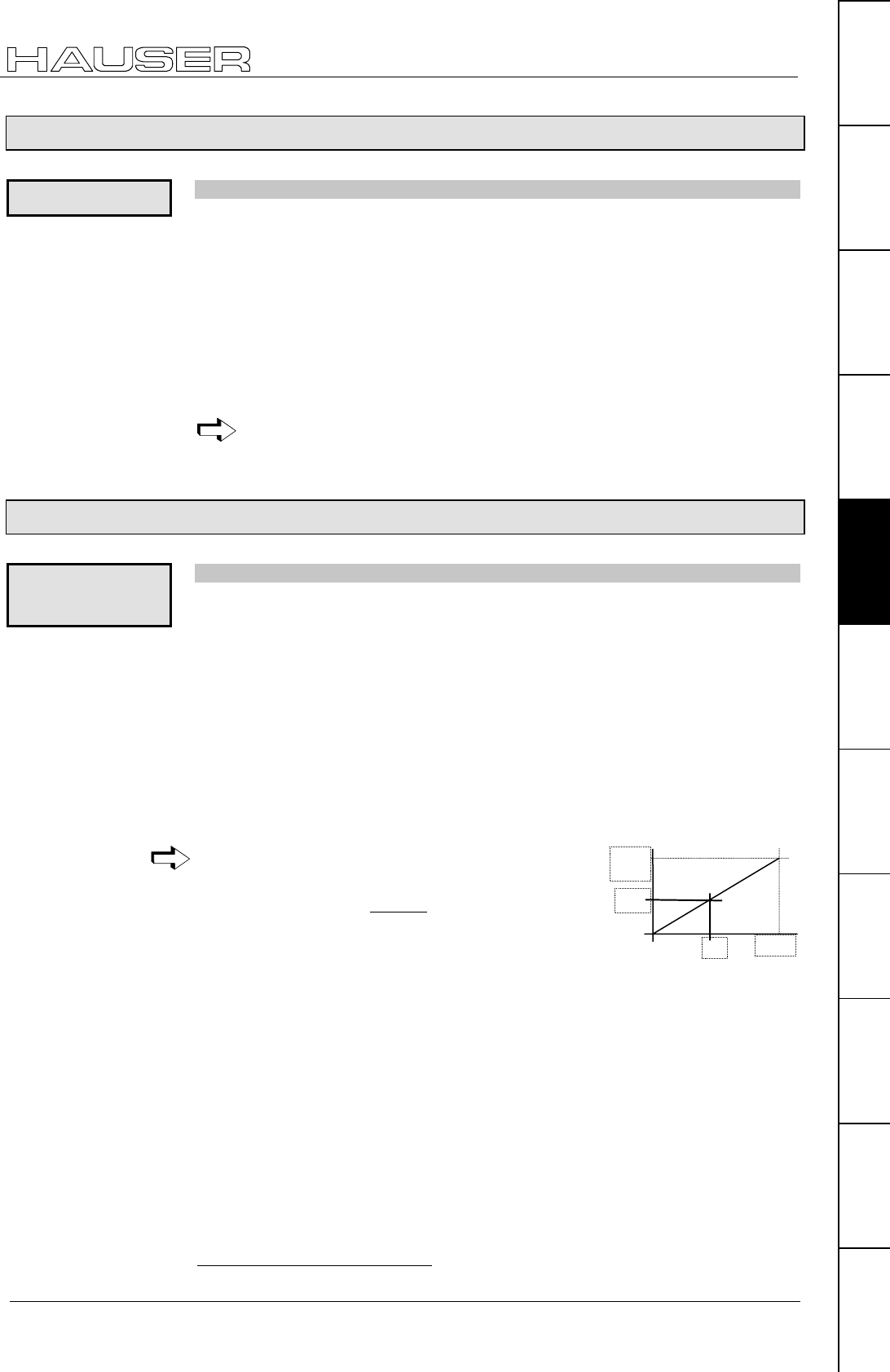
Positioning and control functions
Process velocity [SPEED]
97
Unit
hardware
Connector
assignment / cable
Technical dataConfigurationPositioning and
control functions
Optimization
functions
InterfacesAccessories /
options
StatusParameterError list
8.4.3 Process velocity [SPEED]
Process velocity as % of nominal velocity
(Nominal velocity ≡ nominal speed * travel per motor rotation).
♦
valid until a new value is programmed.
When in speed control mode , direction of rotation is specified by the prefix.
SPEED value
Value: 0.0000001...100%15, a control parameter (P40..P49) or a variable
(V1..V39) e.g. SPEED .P40
Smallest steps = 0.002384min-1
N005: SPEED 70 sets velocity to 70% of nominal speed.
The set velocity can be reduced using the analogue overrride input (X11.6)
(see start-up manual).
8.4.4 Acceleration and braking time [ACCEL]
Specification for acceleration and braking time .
♦
without prefix: time specification for acceleration and decceleration process.
♦
negative prefix: separate time specification for decceleration process.
♦
valid until a new value is programmed.
♦
Acceleration process can be specified using parameter P94 (see Page 75).
♦
If a travel command is interrupted by STOP or BREAK, the STOP / BREAK – ramp
is not executed by ACCEL- but by the value defined as the acceleration time.
ACCEL value
Value: 10...65 000 ms, a control parameter (P40..P49) or a variable (V1..V39) e.g.
ACCEL .P40 (timescale = 10 ms)
The negative prefix for the decceleration time specification must be set
before the control parameters e.g.: ACCEL- .P40 (P40 > 0)
The time specified in ms applies for nominal velocity
(100%). The actual time is proportional to the velocity
selected. Meaning: ACCEL
%100
SPEED
ta =
N005: ACCEL 300 sets the acceleration and deceleration ramp to 300 ms
N006: ACCEL -200 sets the deceleration ramp to 200 (≡200 ms when
SPEED=100%)
15 For asynchronous motors, up to a max. of 300%.
SPEED
Syntax:
Example:
ACCEL
ACCEL-
Note:
Syntax:
Example:
40%
SPEED
100%
ta ACCEL

Operating Instructions COMPAX-M / -S
Setting/resetting an output [OUTPUT]
98
8.4.5 Setting/resetting an output [OUTPUT]
OUTPUT output = 1/0
Output O116...O16
N005: OUTPUT O8=1 Sets output 8
N005: OUTPUT O8=0 Resets output 8
8.4.6 Setting multiple digital outputs [OUTPUT O12=1010]
Multiple outputs can be set simultaneously.
OUTPUT O12=1010
OUTPUT O10=01--011 ("-"17 = is not modified)
O10="0"; O11="1"; O12, O13 are not changed; O14="0"; O15=O16="1".
(this is valid for max. 8 outputs)
♦
A maximum of 8 outputs can be processed per OUTPUT command.
♦
The comparator command "POSR .... OUTPUT ...." is still limited to setting one
output.
8.4.7 Switch off drive unit. [OUTPUT O0]
OUTPUT O0 = number
Number: 0/3: drive subject to torque when brake is open.
1: Drive 9 switched off when brake is closed.
2: Drive switched off when brake is open.
The time behaviour of the final stage and brake can be configured; see Page 123.
Note: The command can only be set within a program with COMPAX XX00 and
COMPAX XX60! (see below!)
OUTPUT O0=1 Drive switched off when brake closed.
8.4.8 OUTPUT O0=... in program
The command OUTPUT O0=0,1,2 can only be programmed on the COMPAX
XX00 and COMPAX XX60 in the program.
No error monitoring is executed during switched off status except for emergency
stop (E55/E56).
16 O1...O6 only if masked via P225.
17 Instead of "-", "." is also an option
OUTPUT
Syntax:
Example:
OUTPUT
O12=1010
Syntax:
Note
OUTPUT O0
Syntax:
Example:
Limitation:
POSA
POSR
SPEED
ACCEL
OUTPUT
Password
SPEED
SYNC
Mark
reference
POSR
SPEED
POSR
OUTPUT
Cam
controller
WAIT
GOTO
GOSUB
RETURN
END
REPEAT
IF I..
Comparison
WAIT Start
GOTO /
GOSUB EXT
IF Error/ Stop
Arithmetic
Position
monitoring
Idle display
Speed
monitoring
Engage /
disengage
brake / final
stage
Variable
voltage

Positioning and control functions
Password [GOTO]
99
Unit
hardware
Connector
assignment / cable
Technical dataConfigurationPositioning and
control functions
Optimization
functions
InterfacesAccessories /
options
StatusParameterError list
This means that all errors which can be acknowledged (e.g. lag errors or resolver
errors), which occur during the switched off status (e.g. by separating the resolver
line) are ignored.
Only errors still present after Power On are displayed.
8.4.9 Password [GOTO]
GOTO number
Number ="302": Deactivates password protection
="270": Activates password protection
Note: You can also use this command in the data record memory.
GOTO 302 Enables programming levels and parameters.
8.4.10 External velocity specification. [SPEED SYNC]
Entry at BDF2: SPEED Ent
COMPAX synchronizes itself to an external velocity specification.
Note: function only applies to COMPAX XX00 with options E2, E4 or E7!
SPEED SYNC cannot be used at the same as the external
position adjustment (switched on via P75 ≠
≠≠
≠ 0)!
Instead of specifying velocity using the SPEED command, the process command
velocity is read externally from the encoder interface when you use SPEED SYNC.
Setting condition: P144="4" and P188="0"
Setting aid: the speed of the motor and sensor is the same when using P98=P83
and the correctly set parameter P143 (pulse speed sensor).
♦
No travel synchronization; use our "Electronic transmission" or "Electronical curve
control" unit variant for this purpose.
External speed set via option E7
Meaning: 10V = 100% of nNominal (P104)
P93=1 or 2
P80=16 (general drive)
P83= distance per motor revolution [µm]
P90=1 [mm]
P144=7 (analogue rpm specification)
Calculation of P98:
0000001601000
143P104P83P
98P ••
••
=
with: P143=1 000 000
P104 in [1/min]
Accuracy data can be found on Page 186
GOTO
Syntax:
Example:
SPEED SYNC
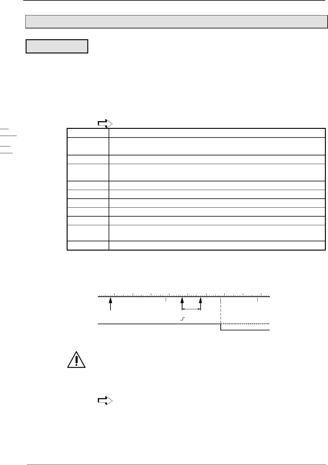
Operating Instructions COMPAX-M / -S
Mark-related positioning [POSR]
100
8.4.11 Mark-related positioning [POSR]
Use this command to position e.g. a mark relative to an external signal.
POSR value
Value: two digits after the decimal point (three for inches) in unit corresp. to P90; a
control parameter (P40..P49) or a variable (V1..V39)
e.g. POSR .P40.
The prefix determines the direction in which the mark is approached.
Note!
POSR 0 is not permitted!
When the mark reference is activated, do not use the POSA command!
I14: Activating mark reference . I14 must be present before the command.
I16: Mark input The rising flank is evaluated (pulse > 0.6ms).
(is read in with a rating of 100µs; the max. error is therefore 100 µs)
O16: With "0", the mark is missing after travel to the mark is completed (P38).
P35: ="1": Mark reference switched on;
="0": Mark reference switched off.
P37,P38: A mark window is specified relative to the start position using P37 and P38.
P37: Minimum travel to mark. (relative to start position).
Range of values for P37: 0.00 ... P38
P38: Maximum travel to mark. (relative to start position).
Range of values for P38: P37 ... 4 000 000
P39: Maximum feed length, if there is no mark in the mark window (relative to start
position).
Range of values for P39: P38 ... P11 or P12
POSR 100 P35="1"; P37=+300; P38=+600; P39=+800; I14="1".
If the mark is between +300 and +600, mark +100 is positioned, if the mark is
outside the window it is positioned to 800.
start point
P37 = +300 P38 = +600 P39 = +800
100
mark on
I16
Driven to
label position
O16
It will go on "0" if no label
come until P38.
Note!
The drive positioning is not limited by P39.
If the mark is within the mark window, COMPAX executes positioning using the
POSR value for a value of the corresponding size, even after P39.
The process range can be limited using P11 and P12.
When the mark reference is switched on, the inputs I14, I15, and I16 are no
longer available for external data record selection (GOTOEXT,
GOSUBEXT).
POSR
Syntax:
Note:
Example:
POSA
POSR
SPEED
ACCEL
OUTPUT
Password
SPEED
SYNC
Mark
reference
POSR
SPEED
POSR
OUTPUT
Cam
controller
WAIT
GOTO
GOSUB
RETURN
END
REPEAT
IF I..
Comparison
WAIT Start
GOTO /
GOSUB EXT
IF Error/ Stop
Arithmetic
Position
monitoring
Idle display
Speed
monitoring
Engage /
disengage
brake / final
stage
Variable
voltage

Positioning and control functions
Preparatory instructions
101
Unit
hardware
Connector
assignment / cable
Technical dataConfigurationPositioning and
control functions
Optimization
functions
InterfacesAccessories /
options
StatusParameterError list
8.4.12 Preparatory instructions
The following command combinations are preparatory instructions for creating
speed step profiles or setting comparator switch points . The prepared positioning
process is started using POSA or POSR. Note the following:
♦
Combined commands can be mixed (POSR SPEED, POSR OUTPUT).
♦
A total of 8 combined commands can be programmed per positioning process.
♦
The positioning values of the command combinations are always positive and
refer to the start point of the positioning process. They represent differences in
travel. The direction is specified by the next positioning command. This can be
relative (POSR) or absolute (POSA) . Meaning:
♦
The positioning values for speed steps, ramp times or comparators always apply
from the point at which positioning starts (for POSA and POSR)
♦
The positioning values for speed steps, ramp times or comparators are numerical
values:
♦
If the following positioning is positive, COMPAX calculates them as positive
values.
♦
If the following positioning is negative, COMPAX calculates them as negative
values.
♦
If a process cycle has been interrupted by "Stop", continue the cycle using
"Start".
♦
The preparatory instructions are canceled by the "Hand+/-", "Find machine zero"
and "Approach real zero" commands.
8.4.13 Changes in speed within a positioning process [POSR SPEED]
Each speed step profile can have a maximum of 8 speed steps. The comparator
value is specified as a relative dimension. It is referenced to the positioning start
point.
POSR value 1 SPEED value 2
Value 1: only positive values permitted (unit corresponds to P90); two digits after
the decimal point (three for inches), a control parameter (P40..P49) or a
variable V1 ... V39.
Value 2: no digits after the decimal point; numerical value, a control parameter
(P40..P49) or a variable V1 ... V39.
e.g.: POSR .P40 SPEED .P41
N001: ACCEL 250 Acceleration and braking time = 250 ms
N002: SPEED 20 Starting velocity = 20%
N003: POSR 150 SPEED 30 1st speed step when starting position ±150, sets velocity to
30%.
N004: POSR 300 SPEED 50 2st speed step when starting position ±300, sets velocity to
50%.
N005: POSR 500 SPEED 80 3st speed step when starting position ±500, sets velocity to
80%.
N006: POSR 900 SPEED 60 4st speed step when starting position ±900, sets velocity to
60%.
N007: POSA -1000 Positioning command to position -1000 (position -1000 is
approached with all of or one part of the speed step profile
depending on the start point).
N008: POSR 200 SPEED 50 Prepares a new speed step profile.
N009: ...
POSR SPEED
Syntax:
Example:

Operating Instructions COMPAX-M / -S
Changes in speed within a positioning process [POSR SPEED]
102
Speed step profile extended by ramp time
Speed step profiling is still possible in the previous version with no restrictions.
♦
In addition to the new velocity, the acceleration time can be defined for the speed
step profile.
This becomes effective at the transition to the defined velocity and remains valid
until a new acceleration time is defined.
♦
The braking time is assigned within the speed step profile, not by using ACCEL-,
but defined by the velocity change.
♦
The deceleration ramp for the target position is defined by the previously set
ramp (braking time applicable before the speed step profile).
Abbreviation: PR x SD y AL z
x, y, z: number, parameter .P40 (P40-P49) or variable .V1 (V1-V39)
PR .P40 SD .V31 AL 200
♦
The last ramp time selected using a prepared command from ACCEL remains
valid for future positioning processes.
♦
The situation with SPEED is same.
♦
A braking time previously defined with ACCEL- remains unaffected.
ACCEL 1000 Generally valid acceleration time
ACCEL -2000 Generally valid braking time
SPEED 25 Generally valid velocity
POSR x SPEED 100 ACCEL 300 1st speed step at position x
POSR y SPEED 10 ACCEL 100 2nd speed step at position y
POSA z Start positioning to z
POSA 0 Return with SD 10, AL100 and AL-2000
Position
Speed
100%
Start x y
z
25%
10%
10%
2000ms
2000ms
100ms
100ms
300ms
1000ms
1 Position x is reached at 25% velocity and 1000ms acceleration time.
2 Position y is reached at 100% velocity and 300ms acceleration time.
3 Position z is reached at 10% velocity and 100ms acceleration time.
4 To stop at position z, a braking ramp of 2000ms is used for early deceleration.
5. After the command POSA 0, the drive returns to the starting point (= position 0). The
drive accelerates for the last set 100 ms to the last set velocity of 10% and returns to
position 0. The braking time of 2000 ms set before the speed step profile is used as the
braking ramp.
Compatibility:
Function:
POSR x SPEED y
ACCEL z
Example:
Note:
Example:
POSA
POSR
SPEED
ACCEL
OUTPUT
Password
SPEED
SYNC
Mark
reference
POSR
SPEED
POSR
OUTPUT
Cam
controller
WAIT
GOTO
GOSUB
RETURN
END
REPEAT
IF I..
Comparison
WAIT Start
GOTO /
GOSUB EXT
IF Error/ Stop
Arithmetic
Position
monitoring
Idle display
Speed
monitoring
Engage /
disengage
brake / final
stage
Variable
voltage
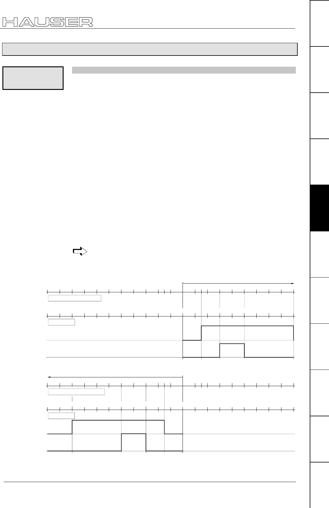
Positioning and control functions
Comparators during positioning [POSR OUTPUT]
103
Unit
hardware
Connector
assignment / cable
Technical dataConfigurationPositioning and
control functions
Optimization
functions
InterfacesAccessories /
options
StatusParameterError list
8.4.14 Comparators during positioning [POSR OUTPUT]
Setting and resetting freely assignable outputs within a positioning process.
A maximum of 8 comparators can be set in one positioning process. The
comparator value is specified as a relative dimension. It is referenced to the
positioning start point.
POSR value OUTPUT output = 1/0
Value: only positives value are permitted (unit corresponds to P90); two digits
after the decimal points (three for inches) a control parameter (P40..P49)
or a variable (V1..V39)
e.g. POSR .P40 OUTPUT A7=1.
N001: ACCEL 250 Acceleration and braking time = 250 ms
N002: SPEED 50 Starting velocity = 50%
N003: POSR 150 OUTPUT A8=1 1st comparator at start position 150, sets output O8 to
1.
N004: POSR 300 OUTPUT A7=1 2nd comparator at start position 300, sets output O7 to
1.
N005: POSR 500 OUTPUT O7=0 3rd comparator at start position 500, sets output O7 to
0.
N006: POSR 900 OUTPUT O8=0 4th comparator at start position ±900, sets output O8 to
0.
N007: POSA 1000 Positioning command to 1000 (Position +1000 is
approached; the travel-dependent comparators are set
once the relative positions have been reached).
N008: POSR 200 OUTPUT O7=1 Prepares new comparators.
Outputs O1 to O6 can also be used as comparators once enabled via P225
(see Page 139).
Diagram of specified example for POSR OUTPUT
0100
starting position
300-150 500
1000
900
200 300 500 700 800 900
absolute position
position relative to starting position
150-300-500
-900
-100-200-300-400-500-600-700-800-900-1000
POSA 1000
400 600
A8
A7
Diagram of example using POSA -1000 as positioning
0100
starting position
300-150 500
1000
900
200 300 500 700 800 900
150-300-500
-900
-100-300-500-600-700-900-1000
POSA 1000
400 600-800 -400 -200
position relative to starting positionen
absolute position
A8
A7
POSR
OUTPUT
Syntax:
Examples:
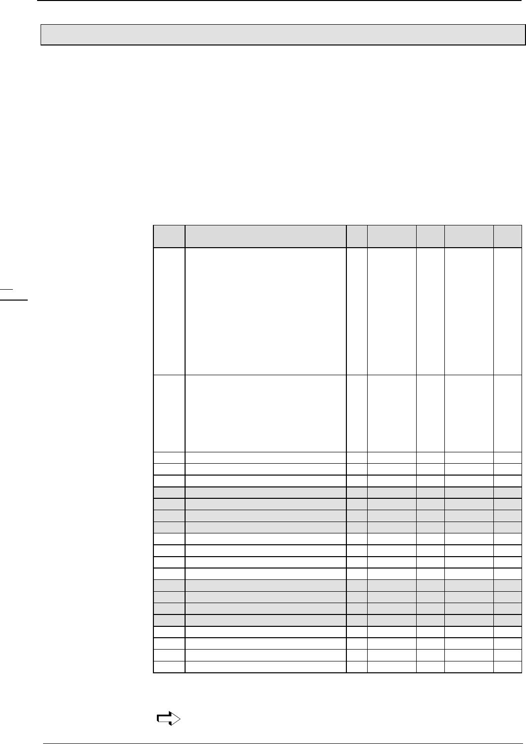
Operating Instructions COMPAX-M / -S
Cam controller with compensation for switching delays
104
8.4.15 Cam controller with compensation for switching delays
With the function "Cam controller", you can switch 4 actuators (switch elements)
dependent on position.
♦
The switching positions are fixed positions within the positioning range.
♦
The reference value for the switching positions can be selected from:
the position actual value (S1) or
the position set point or
the absolute value (S12)
♦
The switching delay of the actuators is compensated for dependent on the speed.
Outputs O9 ... O12
Parametrization occurs via variables in the range V50 ... V70.
No.: Contents Unit min stand
ard
max valid
from
V50 Operation mode cam controller
0: inactive
1: position actual value
(without consideration of P1 and P215)
2: position set point
(without consideration of P1 and P215)
3: reserved
4: S1 (position actual value)
Number range: +/- 4 mill. units (P90)
5: position set point
Number range: +/- 4 mill. units (P90)
6: absolute value (S12)
Number range: +/- 2048 units (P90)
00 VP
V51 Polarity O9...O12 Valence
Bit 9: Polarity O9 256
Bit 10: Polarity O10 512
Bit 11: Polarity O11 1024
Bit 12: Polarity O12 2048
If the corresponding bit is set, then the
relevant output is inverted.
0 0 3840 VP
V52 reserved VP
V53 reserved VP
V54 reserved VP
V55 Position control cam 1 (O9) on* P90 -4 000 000 0.00 +4 000 000 VP
V56 Switch-on lag control cam 1 ms 0 0 1000 VP
V57 Position control cam 1 (O9) off* P90 -4 000 000 0.00 +4 000 000 VP
V58 Switch-off lag control cam 1 ms 0 0 1000 VP
V59 Position control cam 2 (O10) on* P90 -4 000 000 0.00 +4 000 000 VP
V60 Switch-on lag control cam 2 ms 0 0 1000 VP
V61 Position control cam 2 (O10) off* P90 -4 000 000 0.00 +4 000 000 VP
V62 Switch-off lag control cam 2 ms 0 0 1000 VP
V63 Position control cam 3 (O11) on* P90 -4 000 000 0.00 +4 000 000 VP
V64 Switch-on lag control cam 3 ms 0 0 1000 VP
V65 Position control cam 3 (O11) off* P90 -4 000 000 0.00 +4 000 000 VP
V66 Switch-off lag control cam 3 ms 0 0 1000 VP
V67 Position control cam 4 (O12) on* P90 -4 000 000 0.00 +4 000 000 VP
V68 Switch-on lag control cam 4 ms 0 0 1000 VP
V69 Position control cam 4 (O12) off* P90 -4 000 000 0.00 +4 000 000 VP
V70 Switch-off lag control cam 4 ms 0 0 1000 VP
* The switching processes described apply for increasing setpoint and P215=0;
with decreasing setpoint switch off occurs at the same position where switch on
previously occured.
The variables for parametrization of the cam controller are not password
protected!
Function of the
cam controller:
Outputs of the cam
controller
Parametrization of
the cam controller
POSA
POSR
SPEED
ACCEL
OUTPUT
Password
SPEED
SYNC
Mark
reference
POSR
SPEED
POSR
OUTPUT
Cam
controller
WAIT
GOTO
GOSUB
RETURN
END
REPEAT
IF I..
Comparison
WAIT Start
GOTO /
GOSUB EXT
IF Error/ Stop
Arithmetic
Position
monitoring
Idle display
Speed
monitoring
Engage /
disengage
brake / final
stage
Variable
voltage
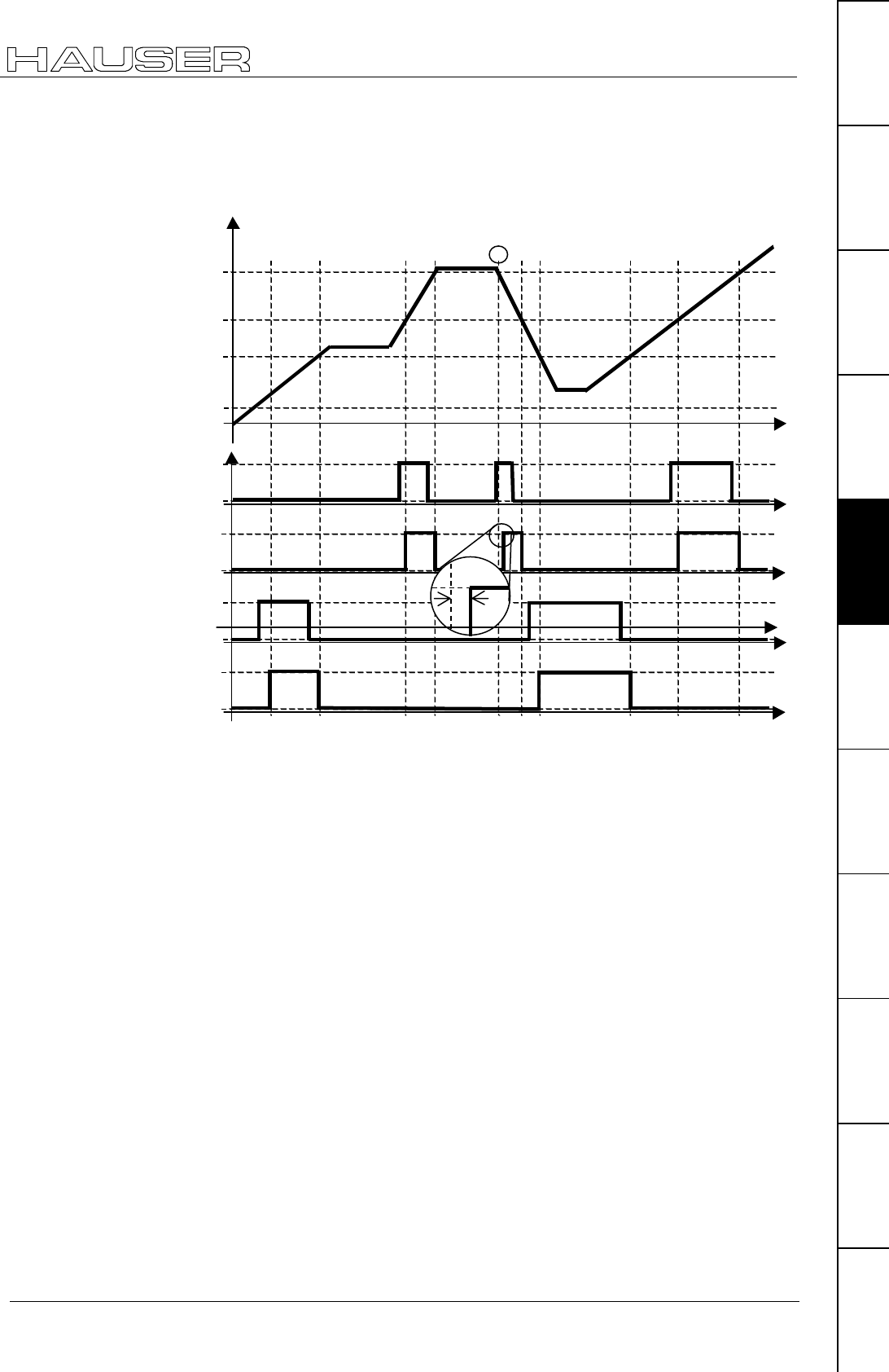
Positioning and control functions
Cam controller with compensation for switching delays
105
Unit
hardware
Connector
assignment / cable
Technical dataConfigurationPositioning and
control functions
Optimization
functions
InterfacesAccessories /
options
StatusParameterError list
With the instruction V0=x (global instruction to all variables), variables V50 ... V70
will also be changed!
Example 1: Normal
positioning
V57
V55
V61
V59
0
1
0
1
0
1
0
1
0
1
0
1
conrtol cam 1
control cam 2
control cam 2
control cam 1
control signal 1
control signal 2
Actuator 1 (effect)
Actuator 1 (effect)
t
t
t
t
t
Position
1
error
COMPAX calculates a travel difference from the lag times of the switch elements
(∆pon and ∆poff). A constant speed is assumed.
The switching signal is (with increasing setpoint)
activated by ∆pon before the control cam position for On and
deactivated again by ∆poff before the control cam position for Off.
Requirements for safe and time correct switching of the cam controller:
The cam positions, as well as the range ∆p before the cam position must be moved
through at constant speed.
Problem point:
In Example 1, point ➀, the idle position is located just above V57, so that the
control cam 1 cannot be activated too early. This means that the switch-on lag of
the actuator cannot be compensated. This causes a switching error.
In this case, COMPAX activates the control cam output immediately after the
relevant positioning command is received.
Note!
Explanation
regarding cam
controller
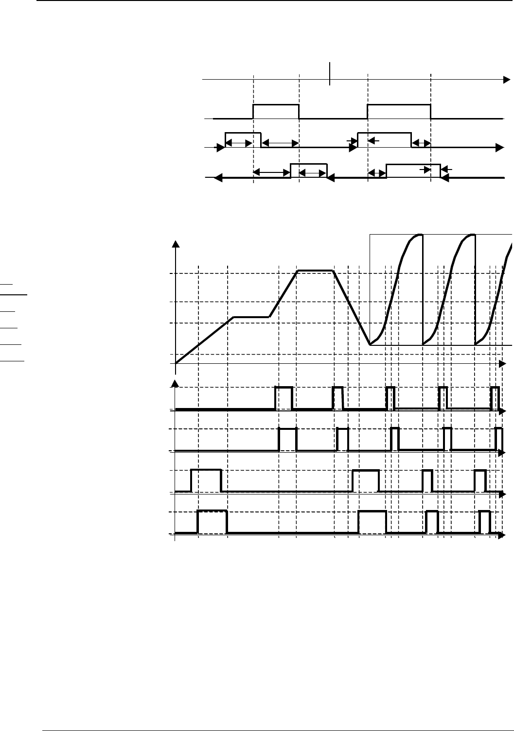
Operating Instructions COMPAX-M / -S
Cam controller with compensation for switching delays
106
Behaviour of the control signal during negative position values, falling
position and P215=0
0
negative positions
S1
positive positions
V57 V55 V61 V59
V58
V56
V56
V58
V60
V60 V62
V62
rising
positions
falling
positions
A10 A9
The relevant distances ∆p resulting from the times are shown.
Example 2: Positioning with subsequent cam operation (COMPAX XX70)
V57
V55
V61
V59
0
1
0
1
0
1
0
1
0
1
0
1
control cam 1
control cam 2
control cam 2
control cam 1
control signal 1
control signal 2
Actuator 1 (effect)
Actuator 2 (effect)
t
t
t
t
t
Position
➁
At position ➁ (reset function to next curve) no compensation is implemented for the
switching delay.
Note:
The cam controller is calculated using a cycle of 1ms.
Explanation:
POSA
POSR
SPEED
ACCEL
OUTPUT
Password
SPEED
SYNC
Mark
reference
POSR
SPEED
POSR
OUTPUT
Cam
controller
WAIT
GOTO
GOSUB
RETURN
END
REPEAT
IF I..
Comparison
WAIT Start
GOTO /
GOSUB EXT
IF Error/ Stop
Arithmetic
Position
monitoring
Idle display
Speed
monitoring
Engage /
disengage
brake / final
stage
Variable
voltage
Positioning and control functions
rogrammable waiting time [WAIT]
107
Unit
hardware
Connector
assignment / cable
Technical dataConfigurationPositioning and
control functions
Optimization
functions
InterfacesAccessories /
options
StatusParameterError list
8.4.16 rogrammable waiting time [WAIT]
Programmable waiting time in ms before the next data record is processed.
WAIT value Value:10...65 000 [ms] a control parameter (P40..P49) or a
variable (V1..V39)
e.g. WAIT .P40 (time pattern 10 ms)
N005: WAIT 500 Sets the waiting time to 500 ms before the next data record is
processed.
8.4.17 Program jump [GOTO]
Program jump to specified data record number.
GOTO data record number
Data record number: 1...250
N045: GOTO 60 Jumps to data record N060
8.4.18 Sub-program jump [GOSUB]
Jump to a sub-program .
GOSUB data record number
Data record number: 1...250
N005: GOSUB 100
N100: ...
N101: ...
...
Nxxx: RETURN
Calls up sub-program
Starts sub-program
Ends sub-program, jumps back to N006
Never use GOTO to jump out of a sub-program or to a sub-program.
8.4.19 Instruction to end a sub-program. [RETURN]
This executes a return jump to the main program.
RETURN
8.4.20 END instruction [END]
END instruction for a REPEAT loop or for the program.
To end a program, you implement a program stop. The data record indicator
is not modified.
END
WAIT
Syntax:
Example:
GOTO
Syntax:
Example:
GOSUB
Syntax:
Example:
Note:
RETURN
Syntax:
END
Syntax:

Operating Instructions COMPAX-M / -S
Start a program loop [REPEAT]
108
8.4.21 Start a program loop [REPEAT]
The following program sequence is run through the number of times
specified until an END instruction appears.
REPEAT value
Value: 1...65 000 a control parameter (P40..P49) or a variable (V1..V39)
e.g. REPEAT .P40
N005: REPEAT 10
N006: ...
N007: END
Starts a program loop, which is run through 10 times
End of loop
A loop can be prematurely exited using GOTO.
8.4.22 Branching [IF I7=1]
Branching related to a control input
IF control input=1/0 GOTO/GOSUB data record number
Control input: I118...I16
IF I7=1 GOTO 010
IF I7=0 GOSUB 010
If I7 = "1", a jump is made to data record N010
If I7 = "0", a jump is made to the sub-program in data record
N010
8.4.23 Binary IF query of inputs [IF I12=101-1]
Multiple inputs can be queried simultaneously.
The inputs are compared with a mask. The mask contains individual bits 1 or 0,
and a space marker (-)19 for "not taken into consideration".
IF I12=101-1 GOTO 123
-> I12 = 1, I13=0, I14=1, I15= "not considered", I16 = 1.
Binary IF querying of status values or outputs is not possible.
A maximum of 8 inputs can be queried per IF instruction.
18 I1...I6 only if masked via P221.
19 Instead of "-", "." is also an option
REPEAT
Syntax:
Example:
IF I7=1
Syntax:
Examples:
IF I12=101-1
Syntax:
POSA
POSR
SPEED
ACCEL
OUTPUT
Password
SPEED
SYNC
Mark
reference
POSR
SPEED
POSR
OUTPUT
Cam
controller
WAIT
GOTO
GOSUB
RETURN
END
REPEAT
IF I..
Comparison
WAIT Start
GOTO /
GOSUB EXT
IF Error/ Stop
Arithmetic
Position
monitoring
Idle display
Speed
monitoring
Engage /
disengage
brake / final
stage
Variable
voltage

Positioning and control functions
Comparative operations
109
Unit
hardware
Connector
assignment / cable
Technical dataConfigurationPositioning and
control functions
Optimization
functions
InterfacesAccessories /
options
StatusParameterError list
8.4.24 Comparative operations
IF <single Operand> <compare> <Operand> GOTO xxx
or
IF <single Operand> <compare> <Operand> GOSUB xxx
a parameter Pxxx or
a variable 20 Vxxx or
a status value Sxxx (S1-S15, S30, S40ff)
A simple Operand or
A constant with max. 8 significant digits
<smaller
>larger
=equals
<> not equal
<= equal to/less than
>= equal to/greater than
Depending on the result of the comparison, a GOTO or GOSUB is carried out.
IF P40>100 GOTO 234
IF V030<>P49 GOTO 123
Within the IF query, operations with logic operators (AND, OR) are not possible.
Writing convention of variables (V0-V39) and control parameters (P40-P49)
For reasons of compatibility, a preceding point (full stop) is expected in the syntax for motion commands:
e.g.: POSA .P40, ACCEL .V10
The new comparison and arithmetic commands will operate without a preceding point (full stop): e.g.:
P41=V10+S1, IF V20 > S2 GOTO 10
8.4.25 Specific processing of data record groups. WAIT START.
Entry at BDF221: WAIT Ent
When this instruction is issued, COMPAX interrupts the programming procedure
until a external START (E5 or via interface) is issued (reaction time <30 ms). For
shorter reaction times, refer to I15 on Page 151.
WAIT Start
8.4.26 Jump with data record selection [GOTO EXT]
Jump with data record selection via the inputs I9 to I16.
Entry at BDF2: GOTO Ent
Data record selection as for GOSUB EXT (see below).
20 for variables, see Page 114.
21 Applies to the manual terminal BDF2/01
Syntax:
Simple Operand:
Operand:
Comparison:
Examples:
Limitation:
WAIT START
Syntax:
GOTO EXT
Operating Instructions COMPAX-M / -S
Sub-program jump with data record selection [GOSUB EXT]
110
8.4.27 Sub-program jump with data record selection [GOSUB EXT]
Entry at BDF2: GOSUB Ent
Jump into a sub-program with data record selection via the inputs I9 to I16.
The bit pattern of inputs I9 to I16 is interpreted as a data record number (binary).
I16............I9 => 27..............20
e.g. 00 010 100 = 20 jumps to sub-program at data record 20.
Note!
If inputs have been assigned functions (e.g. fast start I15 or external position
adjustment I11), they are not taken into consideration when using GOSUB EXT
(read logically as "0"):
The assignments of each of the binary inputs I16...I9 must be taken into
consideration for the individual unit variants (COMPAX XX50M,...).
When the PLC data interface is activated, the commands GOTO EXT and GOSUB
EXT are blocked!
8.4.28 Error handling [IF ERROR GOSUB]
To influence the error reactions.
IF ERROR GOSUB xxx
This instruction can only be programmed as normal IF instructions in the program.
Use this instruction to define the program procedure when an error status occurs.
The error sub-program is called up with a delay by P17 (brake delay). When
performing a WAIT START, COMPAX does not branch into the error sub-program
if an error occurs!
Normally, an error in the COMPAX will cause an actively running move to be
interrupted. Depending on the type of error, the drive is switched off. The program
is however stopped no matter what the error type.
The instruction 'IF ERROR GOSUB xxx' allows you to, e.g. set the outputs to
defined statuses when an error occurs.
If such an instruction has been run once in the program and then an error later
occurs,
♦
the current move is interrupted,
♦
if necessary, the axis is (depending on the error) switched off and
♦
the 'Error program', which has been programmed from program number xxx, is
executed.
The error program has priority over the stop program.
A running stop program is interrupted by the error program and continued after the
error program is executed.
The error program must not contain
♦
any motion commands (POSA, POSR, POSR ..., WAIT POSA, WAIT POSR,
SPEED in the speed control mode, ),
♦
any sub-program jumps (GOSUB, IF ... GOSUB, ...),
♦
any COMPAX XX70 commands,
♦
any approach real zero and find machine zero commands,
♦
any speed step commands (POSR ... SPEED ...) or
♦
comparator commands (POSR ... OUTPUT ...)
GOSUB EXT
IF ERROR
GOSUB
Syntax:
Note!
Function:
Priority:
Error program:
POSA
POSR
SPEED
ACCEL
OUTPUT
Password
SPEED
SYNC
Mark
reference
POSR
SPEED
POSR
OUTPUT
Cam
controller
WAIT
GOTO
GOSUB
RETURN
END
REPEAT
IF I..
Comparison
WAIT Start
GOTO /
GOSUB EXT
IF Error/
Stop
Arithmetic
Position
monitoring
Idle display
Speed
monitoring
Engage /
disengage
brake / final
stage
Variable
voltage

Positioning and control functions
STOP / BREAK handling [IF STOP GOSUB xxx]
111
Unit
hardware
Connector
assignment / cable
Technical dataConfigurationPositioning and
control functions
Optimization
functions
InterfacesAccessories /
options
StatusParameterError list
and is used to bring the individual outputs (e.g. the control output for a pump or a
valve) into a safe status.
Each error program must contain a 'WAIT START' instruction.
The 'WAIT START' instruction causes the programming procedure to stop until an
external QUIT and START occurs.
Then OUTPUT instructions can again be present for resetting the outputs.
There must be a RETURN or END instruction at the end of the error program.
♦
The END instruction stops the program.
♦
The RETURN instruction executes a jump back into the program line which was
previously interrupted. If necessary, an interrupted movement is continued
(provided that the error has been acknowledged).
Main Program Error Program
N001: IF ERROR GOSUB 200 N200: OUTPUT O9=0
N002: OUTPUT O9=1 N201: WAIT START
N003: POSA 0 N202: OUTPUT O9=1
N004: POSA 4000 N203: RETURN
N005: OUTPUT O9=0
N006: GOTO 002
If the axis is now stopped and switched off due to an error, e.g. during POSA 4000
positioning, a sub-program jump is then executed to program line 200 and output
O9 is set to zero at this point.
The program then stops in program line 201 and waits until the error has been
acknowledged and, if necessary, a new start is made.
At program line 202, output O9 is switched on again, at program line 203, a jump is
made back to the previously interrupted program line N004.
The axis executes the rest of the travel to position 4000, and the main program is
then continued at program line N005.
If the error program is concluded with END rather than RETURN, the program
indicator remains in the same position. The program stops running at this point.
Machine zero then has to approached or the program indicator must be reset
explicity.
8.4.29 STOP / BREAK handling [IF STOP GOSUB xxx]
For influencing behavior after STOP or BREAK.
IF STOP GOSUB xxx
This instruction can only be programmed, like normal IF instructions, in the
program. It controls the procedure executed in the program when a stop status
occurs.
Normally, a STOP / BREAK command in the COMPAX will cause a actively
running move to be interrupted; the program is stopped.
The 'IF STOP GOSUB xxx' instruction makes it possible to set the outputs to
defined states in a stopped condition.
If such an instruction has already run in the program and a stop command occurs
later:
♦
the current travel motion is interrupted and then
♦
a 'Stop program' is run, this is stored from program line number xxx.
Error program with
WAIT START
Example:
IF STOP
GOSUB xxx
Syntax:

Operating Instructions COMPAX-M / -S
STOP / BREAK handling [IF STOP GOSUB xxx]
112
The stop program must not contain
♦
any motion commands (POSA, POSR, POSR ..., WAIT POSA, WAIT POSR,
SPEED in the speed control mode, ),
♦
any sub-program jumps (GOSUB, IF ... GOSUB, ...),
♦
any COMPAX XX70 commands,
♦
any approach real zero and find machine zero commands,
♦
any speed step commands (POSR ... SPEED ...) or
♦
comparator commands (POSR ... OUTPUT ...)
and is used to bring the individual outputs (e.g. the control output for a pump or a
valve) into a safe status.
The 'WAIT START' instruction must be included; it stops the programming
procedure before an external START is executed again.
Then OUTPUT instructions can again be present for resetting the outputs.
There must be a RETURN or END instruction at the end of the stop program.
♦
The END instruction stops the program.
♦
The RETURN instruction executes a jump back into the previously interrupted
program line, a travel motion which was interrupted by STOP is continued; the
next command is executed after the BREAK.
The error program has priority over the stop program.
A running stop program is interrupted by the error program and continued after the
error program has run.
Main Program Stop Program
N001: IF STOP GOSUB 240 N240: OUTPUT O9=0
N002: OUTPUT O9=1 N241: WAIT START
N003: POSA 0 N242: OUTPUT O9=1
N004: POSA 4000 N243: RETURN
N005: OUTPUT O9=0
N006: GOTO 002
If the axis has been stopped due to a STOP, e.g. during POSA 4000 positioning,
sub-program jump is then made to program line 240 and output O9 is set to zero at
this point.
The program then stops in program line 241 and waits until a new start occurs.
At program line 242, output O9 is switched on again, at program line 243, a jump is
made back to the previously interrupted program line N004.
The axis therefore executes the rest of the travel to position 4000 and the main
program is then continued at program line N005.
If the stop program is concluded using END rather than RETURN, the program
indicator remains in the same position. The program stops running at this point.
Machine zero has to approached or the program indicator must be reset explicity.
Stop program:
Error program with
WAIT START
Priority:
Example:
POSA
POSR
SPEED
ACCEL
OUTPUT
Password
SPEED
SYNC
Mark
reference
POSR
SPEED
POSR
OUTPUT
Cam
controller
WAIT
GOTO
GOSUB
RETURN
END
REPEAT
IF I..
Comparison
WAIT Start
GOTO /
GOSUB EXT
IF Error/ Stop
Arithmetic
Position
monitoring
Idle display
Speed
monitoring
Engage /
disengage
brake / final
stage
Variable
voltage

Positioning and control functions
Arithmetic
113
Unit
hardware
Connector
assignment / cable
Technical dataConfigurationPositioning and
control functions
Optimization
functions
InterfacesAccessories /
options
StatusParameterError list
8.4.30 Arithmetic
8.4.30.1 Parameter assignments
N001: P40 = 123.456
N002: V19 = P1
The assignments for parameters and variables are defined with an equal sign. The
variables are represented by V0 to V39.
The assignment of variables is also possible as a direct command, e.g. from a
terminal.
• a parameter Pxxx or
• a variable Vxxx (V0 - V39) or
• a curve point Ixxxx (digital or analogue auxiliary functions when using COMPAX
XX70) or
• a curve point Fxxxx (set points when using COMPAX XX70)
• an operand
or
• a simple arithmetic term22
• a parameter Pxxx or
• a variable Vxxx (V1 - V39) or
• a status value Sxxx or
• a constant with max. 8 significant digits + sign + decimal point.
All parameters may be assigned.
The commands "VP" and "VC" (with which the parameters are validated) can be
programmed in the program.
N123: P081=30 (modifies moment of inertia)
N124: VC
N234: P013=10 (modifies lag tolerance)
N235: VP
COMPAX XX70: the curve memory is also accessible:
N200: F5450=0.5 (modifies idle postion of 1st curve)
N201: I5460=128 (modifies master cycle route of 1st curve)
N202: VF (validates curve)
For more information, see operating instructions for electronical curve
control.
22 Curve points can only be modified using an assignment; an arithmetic term is
not allowed.
Syntax:
Note
Items permitted to
the left of the equal
sign:
Items permitted to
the right of the
equal sign:
An operand is:
Example:
Curve memory
Example:

Operating Instructions COMPAX-M / -S
Arithmetic
114
8.4.30.2 Arithmetic and variables
Values can be linked with one another using the four basic types of calculation and
the result can be assigned to a parameter or a variable.
A simple arithmetic term is:
♦
<Operand> <Operator> <Operand> ♦
P10+10; V1-S1; 2*P13; P13/P14;
V7\V3; S12%P40
♦
<Befehl> <Operand> ♦
POSA .V10; SPEED .V30; ...
Operations are not allowed after commands; use variables instead for such cases,
e.g..
N001: V001= S1 + 100.5 not allowed: POSA S1 + 100.5
N002: POSA .V001
Function Example:
+for addition P10+10
-for subtraction V1-S1
* for multiplication 2 * P13
/for division P13/P14
\for whole number division
(formation of the whole number
component)
V7\V3: where V7=30 and V3=7, the result
is:
V7\V3=4
V7/V3=4.2857...; whole number
component= 4
%for the formation of the division
remainder (Modulo) S12%P40 with S12=30 and P40=7, the
result is:
S12%P40=2
S12/P40=4 remainder 2; division remainder
= 2
The following operands may be used:
• constants,
• parameters,
• status values, (S1-S15, S30, S40ff)
• variables (V1-V39); after commands with preceding point (full stop): POSA .V1
Not all status values can be used as operands.
Status values S01 to S15, S30, and S40ff are permitted.
In addition to the 10 user parameters P40 to P49, 39 variables V1-V39 are
available. V0 is used for global assigning of a value to all variables.
The variables are automatically buffer-stored in the ZPRAM, i.e. after Power On
they contain the old value.
When the cam controller is switched off (V50=0), it is possible to use the variables
V51 ... V70 as free variables
After commands the variables (like user parameters P40 to P49) are
preceded by a "point" (full stop): POSA .V1, ACCEL .V22
V0 is used for globally assigning a value to all variables.
Example:
V0=0: V1...V70=0
V0=17: V1...V70=17
With the instruction V0=x, variables V50 ... V70 and therefore the settings of the
cam controller are also changed!
Syntax:
Operators:
Operands
Status values:
Variables:
Note:
Note:
Global assignment:
Note!
POSA
POSR
SPEED
ACCEL
OUTPUT
Password
SPEED
SYNC
Mark
reference
POSR
SPEED
POSR
OUTPUT
Cam
controller
WAIT
GOTO
GOSUB
RETURN
END
REPEAT
IF I..
Comparison
WAIT Start
GOTO /
GOSUB EXT
IF Error/ Stop
Arithmetic
Position
monitoring
Idle display
Speed
monitoring
Engage /
disengage
brake / final
stage
Variable
voltage

Positioning and control functions
Arithmetic
115
Unit
hardware
Connector
assignment / cable
Technical dataConfigurationPositioning and
control functions
Optimization
functions
InterfacesAccessories /
options
StatusParameterError list
N001: P013 = 2 * P013 (Multiplication)
N002: P010 = P040 + 1000.1234 (Addition)
N003: P005 = P005 / 2 (Division)
N004: P250 = P250 - 1 (Subtraction)
N005: V002 = V001 \ 1 (Whole number division)
N006: V3 = S15 % P12 (Modulo)
N007: POSR .V30
Only one operation or command is permitted per program line.
All calculations are executed in 48 bit format (real number); 24 bits before the
decimal point and 24 bits after the decimal point.
Such a real number can be represented with a maximum of 10 places, incl. prefix
and decimal point.
Up to 7 places can be recorded after the decimal point.
Ex. 1234567.89; -1.2345678
If a number overrun occurs while an arithmetic term is being calculated (because
the range of values is not sufficient or if divided by 0), COMPAX reacts as follows:
♦
collective error message E07 is activated.
♦
the program is stopped for safety reasons.
♦
the drive remains powered.
♦
any travel movements are interrupted using the stop ramp.
After Quit and Start, the same command would be processed again and probably
cause another error message.
For this reason, appropriate care should be taken when programming.
The causes of the error are stored in the optimization display (P233/P234=39) and
the last calculation error stored is always the first to be displayed.
Errors occur in the arithmetic due to the systematic errors which arise during the
display of figures in the control processor (the smallest number which can be
displayed is 2-24).
The calculation error can usually be ignored for addition, subtraction and
multiplication.
When dividing, significant discrepancies can result.
The "maximum relative input error" for the division y = x1 / x2 is calculated using
the following formula:
δ∆∆
≤+
xx
x
1
1
x
2
2
x1, x2 ≠ 0 when ∆x1 = ∆x2 = 2-24
or absolute:
∆∆∆
yxxxx
x
=+2112
22
**
x2 ≠ 0 when ∆x1 = ∆x2 = 2-24
x1=12345.6; x2 = 0.0001
Result: y = 123456000
max. relative error: δ≤ 2-24
12345.6 +2-24
0.0001 = 0.000596
max. absolute error: 73585.51=
0.0001
2*12345.6+2*0.0001
=y 2
-24-24
∆
Arithmetic and
variable
examples:
Number format:
Dealing with
calculation errors:
Accuracy of
calculations:
Note!
Division y = x1 / x2
Example:

Operating Instructions COMPAX-M / -S
Arithmetic
116
To include the actual position in a calculation, for example, you may assign as
follows:
N100: V030=S1
or
N100: V030= S1 + 10
The variable V030 derived in this way can be used later, for example, in a
positioning instruction as a preset target.
After Power On, the variables retain the old value as before Power Off as they are
stored in the ZPRAM. With the special instruction V000=x, all variables (on the cam
controller settings) are set to the value x.
Writing convention of variables (V0-V39) and control parameters (P40-P49)
For reasons of compatibility, a preceding point (full stop) is expected in the syntax for motion commands:
e.g.: POSA .P40, ACCEL .V10
The new comparison and arithmetic commands will operate without a preceding point (full stop): e.g.:
P41=V10+S1, IF V20 > S2 GOTO 10
Read status and
assign variables
Initializing
variables:
POSA
POSR
SPEED
ACCEL
OUTPUT
Password
SPEED
SYNC
Mark
reference
POSR
SPEED
POSR
OUTPUT
Cam
controller
WAIT
GOTO
GOSUB
RETURN
END
REPEAT
IF I..
Comparison
WAIT Start
GOTO /
GOSUB EXT
IF Error/ Stop
Arithmetic
Position
monitoring
Idle display
Speed
monitoring
Engage /
disengage
brake / final
stage
Variable
voltage
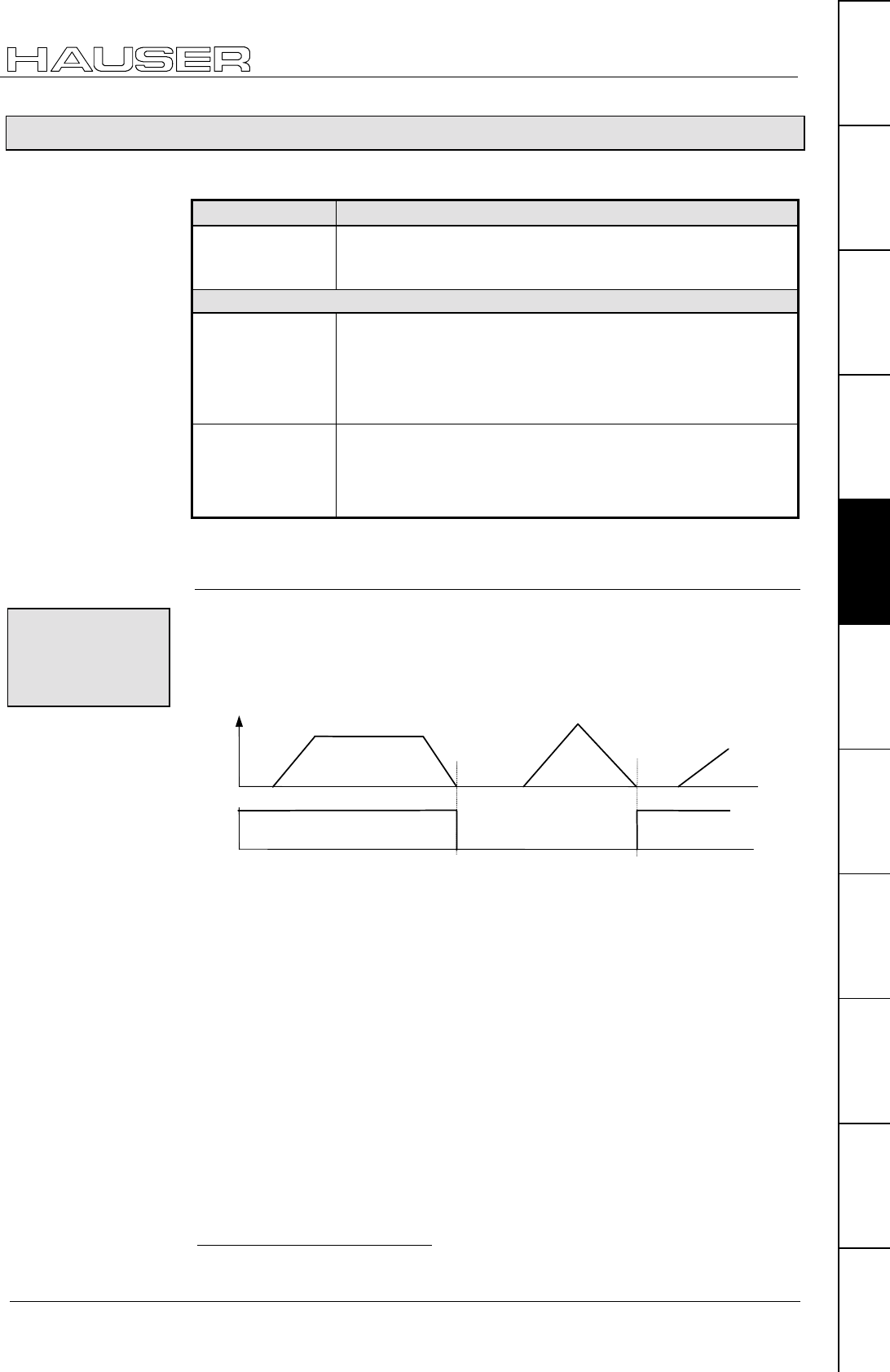
Positioning and control functions
Position monitoring (P93=1, 2, 3)
117
Unit
hardware
Connector
assignment / cable
Technical dataConfigurationPositioning and
control functions
Optimization
functions
InterfacesAccessories /
options
StatusParameterError list
8.4.31 Position monitoring (P93=1, 2, 3)
There are 2 settings for O5 "Position reached" which are set with P227:
P227 bit 423 ="1" Meaning / function
OM124 O5 toggles when the position is reached
O5 toggles after every new positioning when position is
reached.
P227 bit 4 ="0"
P14>0, small
values
(small in comparison
with the process
travel)
OM2
O5 = "1": nominal value reached and lag error < P14
O5="1" if set point generator has finished the ramp and the lag
error is smaller than P14.
If the lag error after O5="1" is greater than P14, then O5 = "0"
until the lag is again less than P14.
P14>>0, large
value
(large in comparison
with process travel)
OM3
O5 = "1": nominal value reached (independent of P14)
O5 = "1" as soon as the set point generator has finished the
ramp and stays at "1" until the start of the next positioning
move.
Functional description:
O5 is toggled (=changed, i.e. from O5="1" to O5="0", from O5="0" to O5="1") after
every positioning move (set point generator has reached target position) .
When an error occurs (Exx is indicated), O5 stays at the current value.
Can be adjusted using: P227 bit 4 ="1"
V
O5
t
t
With this function you can use a host PLC for precise tracking of the COMPAX
positioning. You will find a description of this from Page 122.
23 Bit counting begins with 0.
24 OM: Operating mode
OM1: O5
toggles when
the position is
reached
Example:
PLC - sequential
step tracking
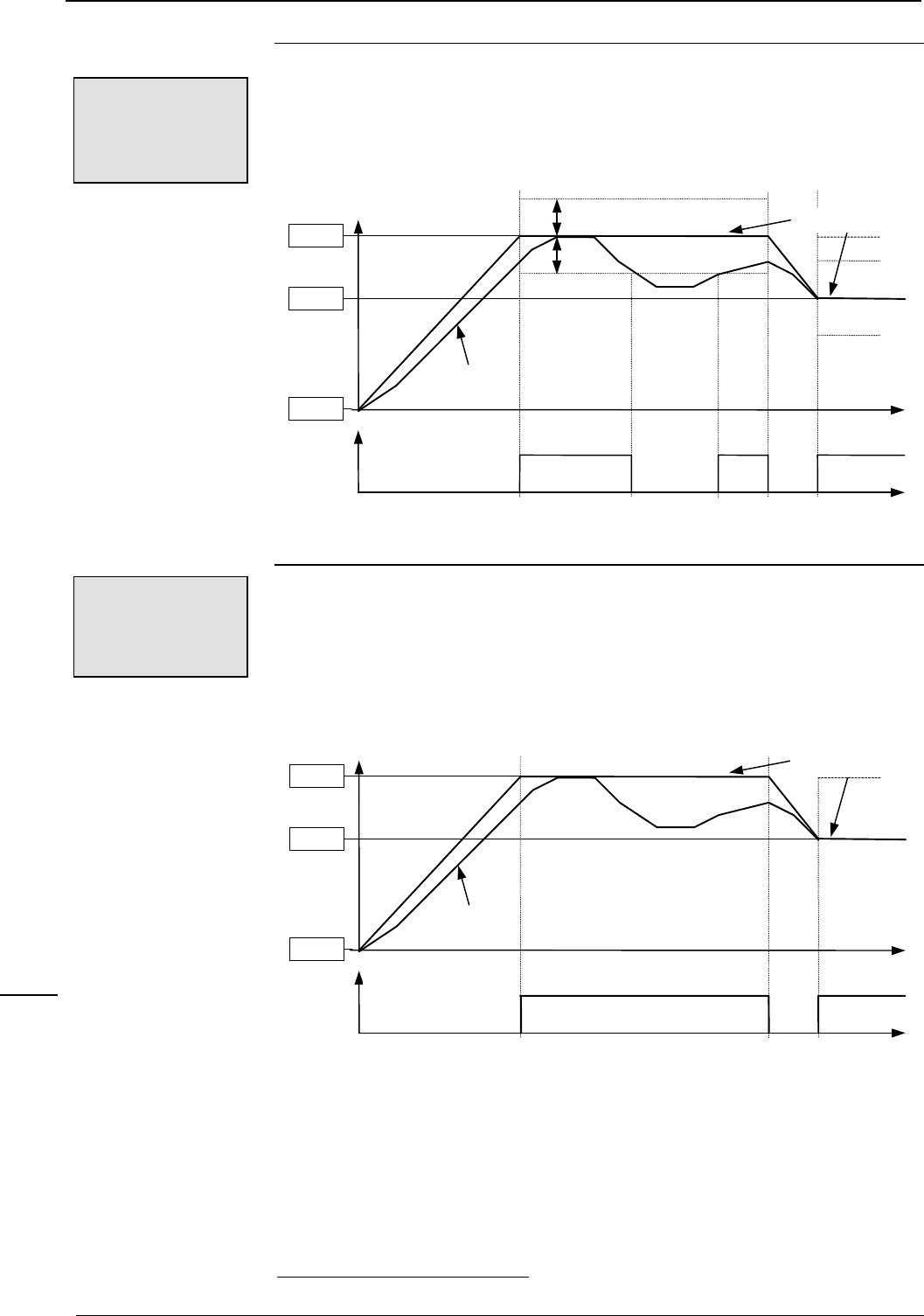
Operating Instructions COMPAX-M / -S
Position monitoring (P93=1, 2, 3)
118
O5="1": nominal value on nominal value sensor reached and lag error < P14.
If the lag error is again > P14, then O5="0" is set.
Can be adjusted using: P227 bit 4 ="0" (default setting)
P14
t
t
Position
O5
Actual value
of position
Target positions
Position 0
Position 2
Position 1
For purposes of clarity a poor loop setting is shown here.
O5="1": nominal value on nominal value generator reached (independent of P14,
since P14 is set as very large value)
Can be adjusted using: P227 bit 425 ="0" (default setting)
t
t
Position
O5
Actual value
of position
Target positions
Position 0
Position 2
Position 1
A poor controller setting has been selected by way of illustration.
25 Bit counting begins with 0.
OM2: O5 = "1":
nominal value
reached and lag
error < P14
Example:
OM3: O5 = "1":
nominal value
reached
(independent of P14)
Example:
POSA
POSR
SPEED
ACCEL
OUTPUT
Password
SPEED
SYNC
Mark
reference
POSR
SPEED
POSR
OUTPUT
Cam
controller
WAIT
GOTO
GOSUB
RETURN
END
REPEAT
IF I..
Comparison
WAIT Start
GOTO /
GOSUB EXT
IF Error/ Stop
Arithmetic
Position
monitoring
Idle display
Speed
monitoring
Engage /
disengage
brake / final
stage
Variable
voltage
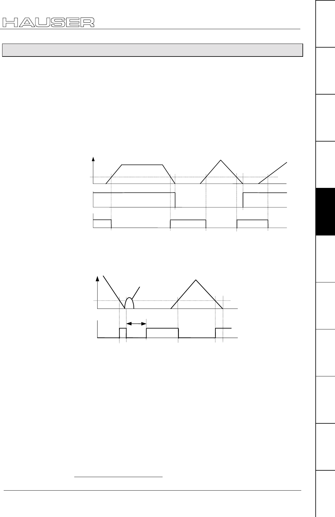
Positioning and control functions
Idle display
119
Unit
hardware
Connector
assignment / cable
Technical dataConfigurationPositioning and
control functions
Optimization
functions
InterfacesAccessories /
options
StatusParameterError list
8.4.32 Idle display
Display showing whether the axis is at standstill or moving.
The display is set to output O2 using the setting P227 bit 126 ="1" ; the standard
function of O2 "No warning" no longer applies in this case.
P229 then serves as a switching threshold, above which an idle condition is
reported with O2="1" and indicated in per-thousands (€ of P104) of nominal speed.
Nominal speed < P229: O2="1"; drive at standstill
Nominal speed ≥ P229: O2="0"; drive moving
P229 = 0: O2="0"; no idle display
Range of numbers P229: 0 - 255‰
P227 bit 1 ="0" O2 assigned the "No warning" display (default value).
V
P229
O5
Ba1
O2
t
t
t
To avoid O2 continuously switching over during nominal speed value disturbance
(during synchronization applications), a minimum pulse time (≡ minimum
positioning time) is defined.
Once nominal speed < P229 has been detected and P229 has then been
exceeded again, the next nominal speed check is executed after 50 ms.
V
P229
O2
t
t
50ms
Disturbance
26 Bit counting begins with 0.
Example:
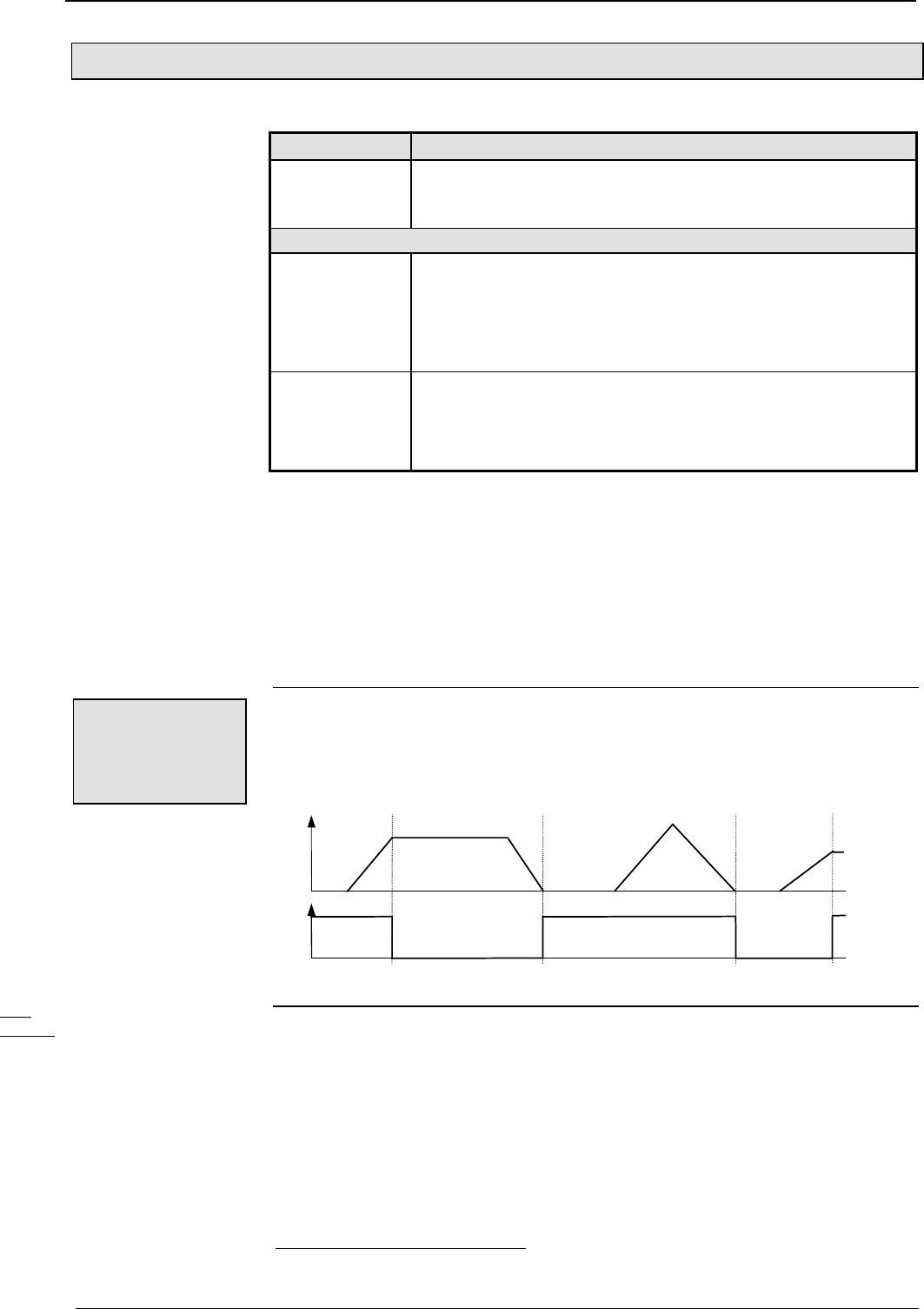
Operating Instructions COMPAX-M / -S
Speed monitoring in speed control mode (P93="4")
120
8.4.33 Speed monitoring in speed control mode (P93="4")
There are 2 settings for O5 "Position reached" which are set with P227:
P227 Bit 4=127 Meaning / function
OM128:O5 toggles when speed is reached
O5 toggles after every new speed definition when speed is
reached.
P227 bit 4 ="0"
P14>0, small
values
(small in comparison
with the changes in
speed)
OM2:
O5 = "1": nominal value reached and < P14
O5="1" if set point generator has finished the ramp and the
speed difference is smaller than P14.
If, after O5="1", the speed difference is again greater than P14,
then O5 = 0 until the difference is again less than P14.
P14>P15
(large in comparison
with changes in
speed)
OM3:
O5 = "1": nominal value reached (independent of P14)
O5=1 as soon as the set point generator has reached the set
speed, and stays at "1" until the next speed change.
Functional description:
In speed control mode, P14 is given as a percentage of the set speed.
In addition, the speed is checked against the speed tolerance defined in P13.
P13 is defined in speed control mode as a percentage of the set speed and is an
absolute limit.
Speed difference > P13: error E10 is triggered
When P13=0, error E10 (and E49) can be switched off.
O5 is toggled (=changed, i.e. from O5="1" to O5="0", from O5="0" to O5="1")
following every speed change (set point generator has reached demanded speed)
In case of error (Exx is indicated), O5 remains at the current value.
Can be adjusted using: P227 bit 4 ="1"
V
O5
t
t
27 Bit counting begins with 0.
28 OM1: operating mode 1
Special features
in speed control
mode:
OM1: O5
toggles when
speed is
reached
Example:
POSA
POSR
SPEED
ACCEL
OUTPUT
Password
SPEED
SYNC
Mark
reference
POSR
SPEED
POSR
OUTPUT
Cam
controller
WAIT
GOTO
GOSUB
RETURN
END
REPEAT
IF I..
Comparison
WAIT Start
GOTO /
GOSUB EXT
IF Error/ Stop
Arithmetic
Position
monitoring
Idle display
Speed
monitoring
Engage /
disengage
brake / final
stage
Variable
voltage
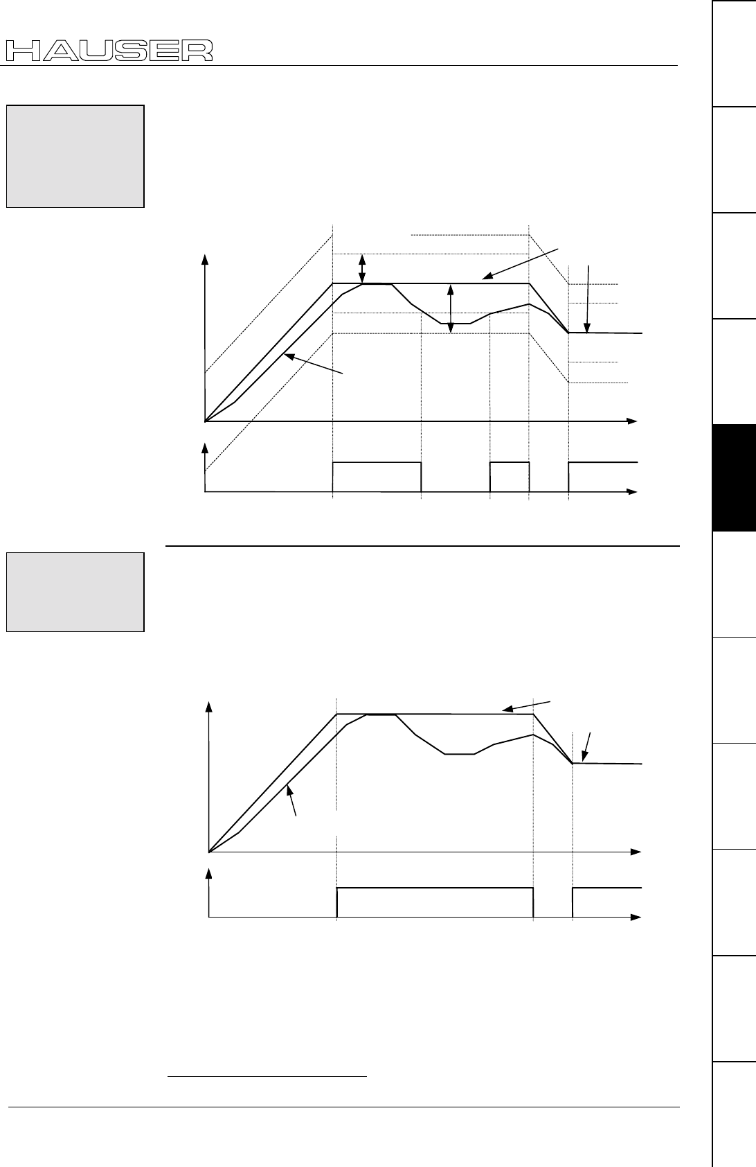
Positioning and control functions
Speed monitoring in speed control mode (P93="4")
121
Unit
hardware
Connector
assignment / cable
Technical dataConfigurationPositioning and
control functions
Optimization
functions
InterfacesAccessories /
options
StatusParameterError list
O5="1": nominal value reached on nominal value generator and speed deviation
< P14.
If the speed deviation returns to > P14, O5="0" is set.
Can be adjusted using: P227 bit 4 ="0" (default setting)
P14
s
p
eed
P13
t
t
O5
Programmed
demanded
s
p
eed
A
ctual value
If the actual value moves outside P13, error E10 is triggered.
O5="1": nominal value on nominal value generator reached (independent of P14
asP14 is set as a very large value)
Can be adjusted using: P227 bit 429 ="0" (default setting)
S
p
eed
O5
Actual value
Programmed
demanded
speed
29 Bit counting begins with 0.
OM2: O5 = "1":
nominal value
reached and
speed error <
P14
Example:
OM3: O5 = "1":
nominal value
reached
(independent of P14)
Example:
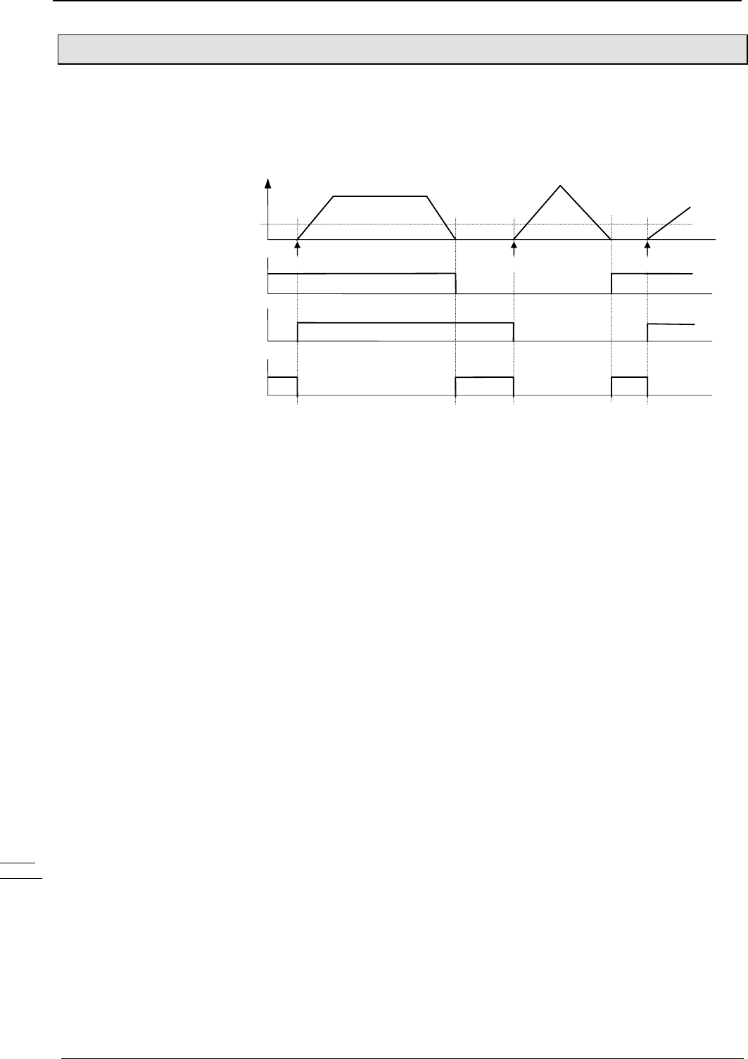
Operating Instructions COMPAX-M / -S
PLC sequential step tracking
122
8.4.34 PLC sequential step tracking
Use the function "O5 toggles when position/speed reached" and a marker in the
PLC to implement precise tracking of the COMPAX.
This also recognizes positioning processes which are completed again during the
next PS cycle.
V
P229
PLC internal
position reached
Flag
PLC ⊕
O5
Flag
PLC
O5 POSAPOSR POSR
The PLC marker is toggled when a positioning command is transmitted.
The "EXCLUSIVE-OR" operation of the PLC marker and output O5 can be
processed as a PLC-internal "Position reached" message.
Implementation:
POSA
POSR
SPEED
ACCEL
OUTPUT
Password
SPEED
SYNC
Mark
reference
POSR
SPEED
POSR
OUTPUT
Cam
controller
WAIT
GOTO
GOSUB
RETURN
END
REPEAT
IF I..
Comparison
WAIT Start
GOTO /
GOSUB EXT
IF Error/ Stop
Arithmetic
Position
monitoring
Idle display
Speed
monitoring
Engage /
disengage
brake / final
stage
Variable
voltage
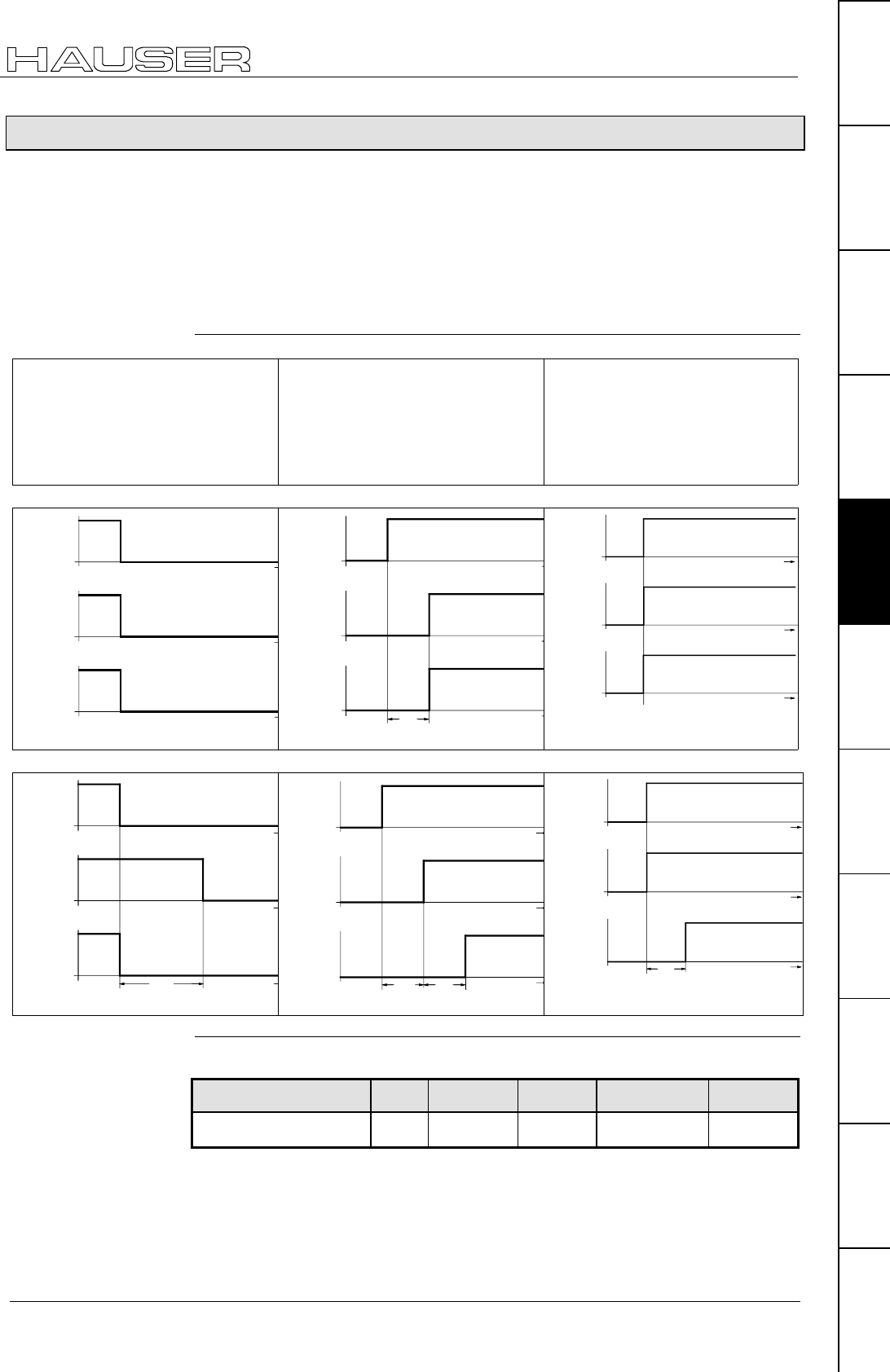
Positioning and control functions
Engaging and disengaging the motor brake
123
Unit
hardware
Connector
assignment / cable
Technical dataConfigurationPositioning and
control functions
Optimization
functions
InterfacesAccessories /
options
StatusParameterError list
8.4.35 Engaging and disengaging the motor brake
COMPAX controls the idle holding brake of the motor and final stage. The time
behaviour can be set using P17 and P211 Bit 2.
If you are using an axis which is under torque when idle (e.g. when using a z axis),
the drive can be engaged and disengaged in a manner which ensures that the load
does not move. To do this, the drive remains powered during the reaction time of
the idle holding brake. This can be set using P17 (see following diagrams).
Final stage blocked by:
♦
error or
♦
OUTPUT O0="1" or
♦
emergency STOP.
The final stage is enabled via:
♦
quit or
♦
OUTPUT O0="0" or
♦
once Power is on
with P211 Bit 2="0".
The final stage is enabled
via:
♦
OUTPUT O0="0"
P211 Bit 2="1"
(the lag of 0.5s is switched off)
P17=0
t
disabled
power out-
put stage
enable
t
de-energised
t
close
brake
open
energised
t
t
t
0,5s
disabled
power out-
put stage
enable
de-energised
close
brake
open
energised
t
t
t
disabled
power out-
put stage
enable
de-energised
close
brake
open
energised
P17>0
t
t
t
P17
disabled
power out-
put stage
enable
de-energised
close
brake
open
energised
t
disabled
power out-
put stage
enable
t
de-energised
energised
t
close
brake
open
0,5s P17
t
t
t
P17
disabled
power out-
put stage
enable
de-energised
close
brake
open
energised
Meaning Unit Min. Value Standard Maximum value Applies to ...
Braking delay ms 0 0 500 VP
Application:
Range of values
for P17:
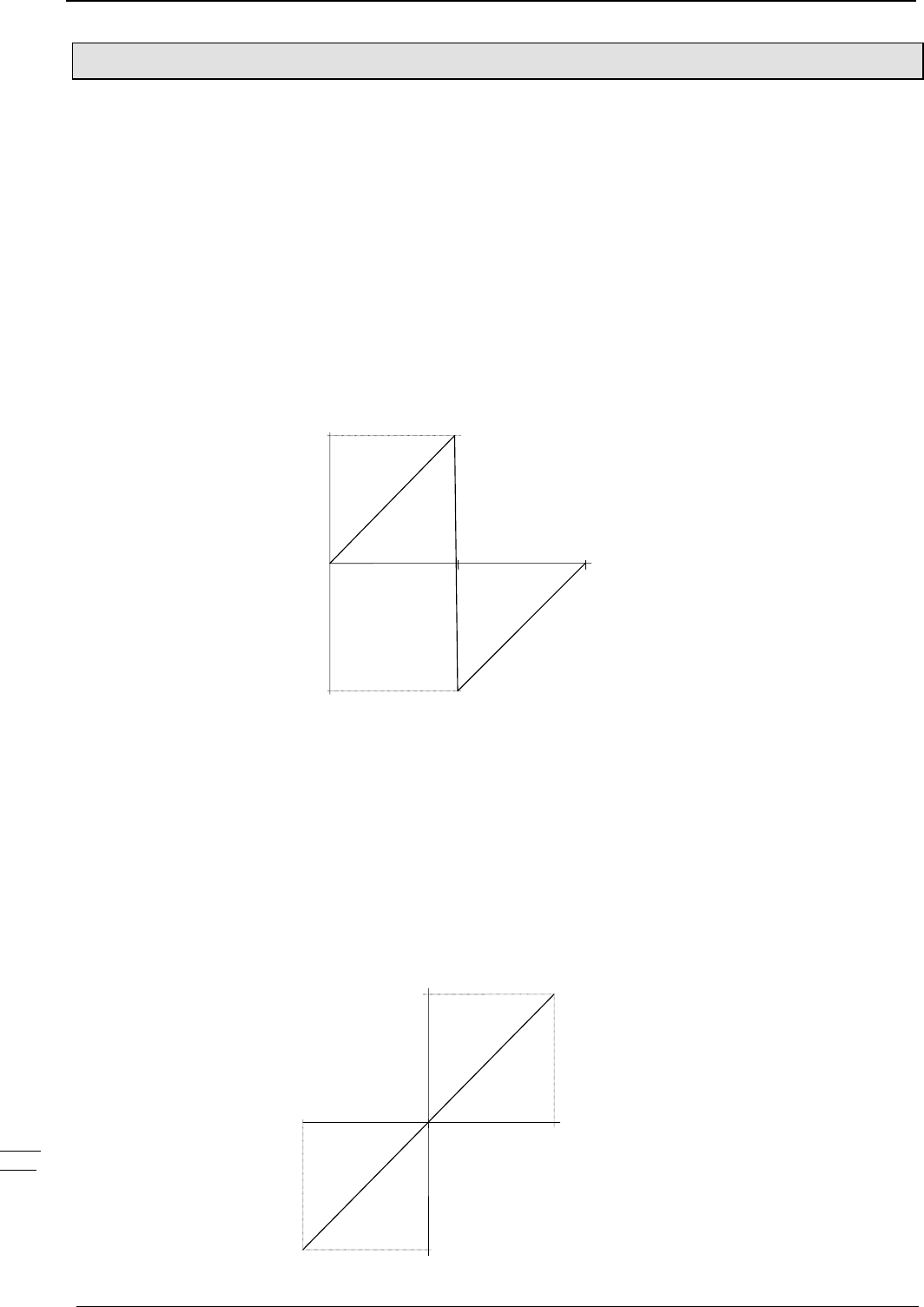
Operating Instructions COMPAX-M / -S
Output of variable voltage
124
8.4.36 Output of variable voltage
The direct output of variable voltage is supported via the D/A monitor channels 0 to
3.
Addressable using parameters P76 (channel 2) and P77 (channel 3)
P76 Channel 2 X11/4
P77 Channel 3 X11/5
Resolution: 8 bit (incl. sign); corresponds to a resolution of 80 mV
Range: -10V...+10V
The calculation for output on the 8 bit channels 2 & 3 is as follows:
Parameter setting for required voltage U (-10V ... +10V)
P76 (P77) = 39 + Y (39,Y)
39: selection of voltage output
For positive voltage: Y = U * 0.0101067 / 10V
For negative voltage: Y = U * 0.0101067 / 10V + 0.0202134
(Note: set U negative in the 2nd formula)
-10.0V
+9.96V
0.0202134
0.0101067
Addressable using P71 (channel 0) and P72 (channel 1)
P71 Channel 0 X17/1
P72 Channel 1 X17/2
Resolution: 12 bit (incl. sign); corresponds to a resolution of 5 mV
Range: -10V...+10V
The calculation for the output on the 12-bit channels 0 and 1 is as follows:
Parameter setting for required voltage U (-10V ... +10V)
P71 (P72) = Y
P73 (P74) = 39: selection of voltage output
Y = U * 101067 / 10V
-10.0V
+10.0V
0.010106
-0.0101067
Service D/A
monitor (channels
2 & 3):
Value before
decimal point:
Value after decimal
point:
Characteristic
curve:
Option D/A
monitor (channels
0 & 1):
Calculating the
output value:
Characteristic
curve:
POSA
POSR
SPEED
ACCEL
OUTPUT
Password
SPEED
SYNC
Mark
reference
POSR
SPEED
POSR
OUTPUT
Cam
controller
WAIT
GOTO
GOSUB
RETURN
END
REPEAT
IF I..
Comparison
WAIT Start
GOTO /
GOSUB EXT
IF Error/ Stop
Arithmetic
Position
monitoring
Idle display
Speed
monitoring
Engage /
disengage
brake / final
stage
Variable
voltage

125
Unit
hardware
Connector
assignment / cable
Technical dataConfigurationPositioning and
control functions
Optimization
functions
InterfacesAccessories /
options
StatusParameterError list
8.5 Optimization functions
Important requirements for a rapid, stable adjustment are the correct information
about the physical characteristic values of the application. COMPAX requires the
following data:
♦
The parameters of the motor.
For Parker – standard motors, select the connected motor type from a list; the
relevant parameters are stored in the ServoManager.
For other motors, the relevant parameters P100-P133 must be set according to
the connected motor (see from Page 91).
♦
The parameters of the application.
These are mainly the moments of inertia (with and without load) that the drive
has to move, which are set, depending on the drive type, via the parameters
P80 ... P92.
♦
Dependent on the sensor system, you can select from 2 structure variants; these
also contain (set via the ServoManager) fixed settings of optimizing parameters.
The standard structure corresponds to the previous COMPAX control structure.
With the standard structure, you can directly transfer previous, already
optimized parameter sets.
♦
After this, the optimal control dynamic is set by increasing the stiffness (P23).
This is usually sufficient to obtain good control results.
User-defined settings
♦
For further optimization, you can adapt the parameters of the set structure
variants optimally to your application (user-defined settings).
♦
As another alternative, you can select structure variant 3 and optimize it with the
relevant parameters.
Optimizing the movement cycle
♦
At the end of every optimization of the control accuracy, the movement cycle
must be optimized. For this, use the pre-control parameters P25, P26, P69 and
P70.
Optimizing with the ServoManager:
Use the menu "Online: Parameters" to change the optimizing parameters
directly in COMPAX (these settings are accepted after modification with
"Return").
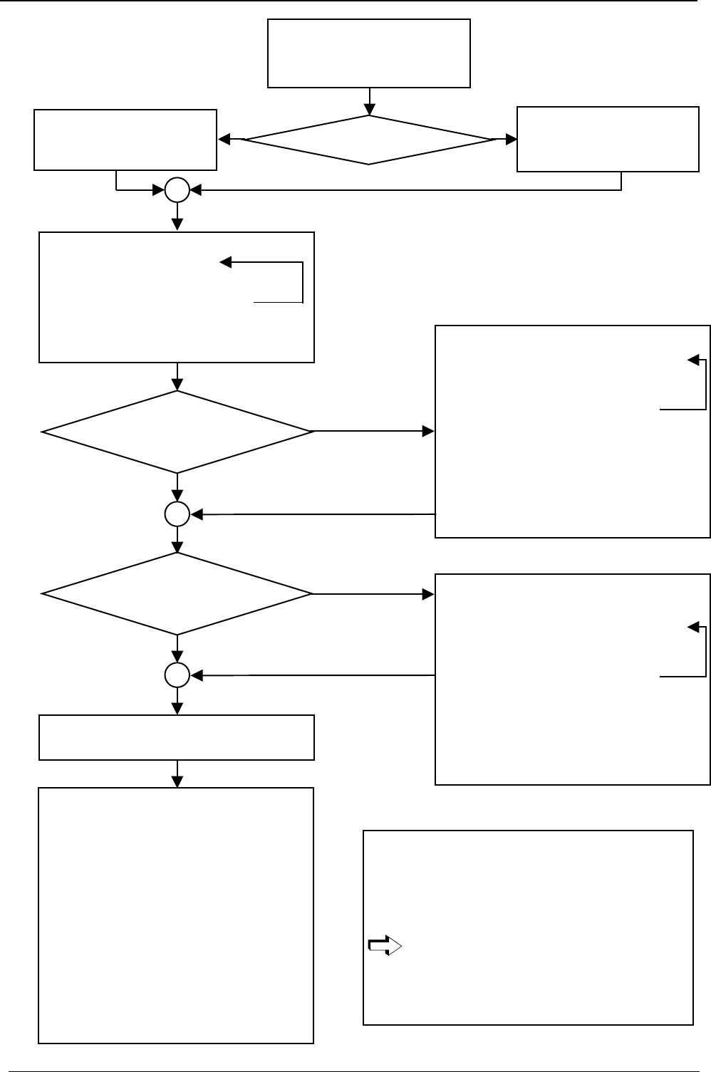
Operating Instructions COMPAX-M / -S
Output of variable voltage
126
Optimization
process:
Note
♦ The arrows behind the parameters show the preferred
direction for the parameter optimization.
↓Reduce parameter
↑Increase parameter
↓↑ Both directions could lead to a better setting.
The optmizing direction shown usually leads
to a good control result in our experience:
however, this cannot apply to every
application case!
Sensor
?
Select structure/parameter
variant 1
P59=4 (Optimise P24 if necessary)
Select structure/parameter
variant 2
P59=3 (Optimise P24 if necessary)
Set motor
Configure drive type:
Parameters P81 ... P92
Motor with
resolver
Motor with
SinCos
Increase control dynamic
Increase P23
Travel slowly over the positioning range
⇒ stable, quiet travelling
⇒ unstable, unquiet travelling
(no longer corresponds to to the requirements)
Reset P23 to the last settin
g
User-defined settings
Modify P56 ↓↑ (D section rpm controller)
Increase P23
Travel slowly over the positioning range
⇒ stable, quiet travelling
⇒ unstable, unquiet travelling
(no longer corresponds to to the requirements)
Reset P23 & P56 to the last setting
Implement the same process for P57 ↓ (lag D
sectionl), P58 ↓ (lag rpm filter) and P151 ↓↑
(monitor speed)!
Optimizing the movement cycle
Optimise pre-control parameters P25 ↓↑ (rpm
pre-control), P26 ↓ (acceleration pre-control), P69
↓ (current pre-control) and P70 ↓ (return pre-
control).
Check current restriction:
During acceleration/braking, the current limit
should not be reached or only briefly.
The optimizing display (P233/234=13 and 14)
shows the time in which the controller is operating
at the current limit.
Use the pre-control parameters or increase
ACCEL to reduce the "time at current limit".
Further
optimization?
Further
optimization? User-defined settings with variant 3
(P59= 8)
Modify P56 ↓↑ (D section rpm controller)
Increase P23
Travel slowly over the positioning range
⇒ stable, quiet travelling
⇒ unstable, unquiet travelling
(no longer corresponds to to the requirements)
Reset P23 & P56 to the last setting
Implement the same process for P57 ↓ (lag D
section), P58 ↓ and (lag rpm filter)!
y
es
y
es
no
no
Evaluate results.
Set best result.
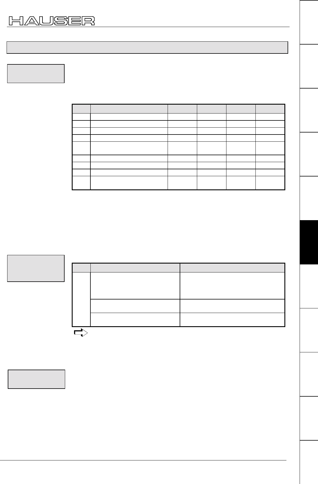
127
Unit
hardware
Connector
assignment / cable
Technical dataConfigurationPositioning and
control functions
Optimization
functions
InterfacesAccessories /
options
StatusParameterError list
8.5.1 Optimization parameters
In addition to the standard structure (which corresponds to the previous COMPAX
control structure), you can select from 3 structure variants.
These include, in addition to a specific control structure, pre-defined settings for
specific optimizing parameters. By selecting the individual structures in the
ParameterEditor, the following parameters can be set:
No. Meaning Standard Variant 1 Variant 2 Variant 3
P59 Structure switch measuring 0 4 3 8
P56 D section rpm controller (%) 0 40 40 40
P57 Filter acceleration (%) 100 175 350 100
P58 Lag rapid rpm signal (%) 100 0 0 100
P50 Monitor 100
(switched off)
101
(switched on)
101
(switched on)
100
(switched off)
P151 Monitor speed (%) 30 30 30 30
P27 Moment of inertia (%) 100 100 85 100
P69 Return pre-control (%) 0 100 100 100
P70 Current pre-control value
(%)
0 100 100 100
Standard: Previous COMPAX control structure; use this structure if you already
have optimized parameter sets.
Variant 1: Structure switch: Variant 1 for resolver
Variant 2: Structure switch: Variant 2 for SinCos
Variant 3: Structure switch: Variant 3 "Rapid rpm controller"
The structure switch measuring (P59) permits the following settings:
No. Meaning Settings
Structure switch measuring 0: Standard
4: Variant 1 (for resolver)
3: Variant 2 (for SinCos)
8: Variant 3 (rapid rpm controller)
Sensitive stiffness (P23)
Larger setting range for P23
+16
P59
Sensitive D section (P56)
Larger setting range for P56
+65536
The D section is reduced by 1/256.
By selecting a structure variant with the structure switch P59, no further
parameters are influenced.
Only by selecting a variant through ServoManager (menu parameters:
controller structure / monitor) can complete parameter sets (as described
above) be set.
The stiffness is proportional to the controller speed.
Nominal value: 100% Range: 10%...5000%
Control is faster. The control circuit starts from a critical value. Set the stiffness so
that sufficient safety distance from the critical value is ensured.
Control is slower. This increases lag error. Current limitation is reached later.
Structure
variants:
Structure and
parameter settings
using the
ServoManager:
P59: Structure
switch
measuring
P23: stiffness of
drive
Increase stiffness
Reduce stiffness
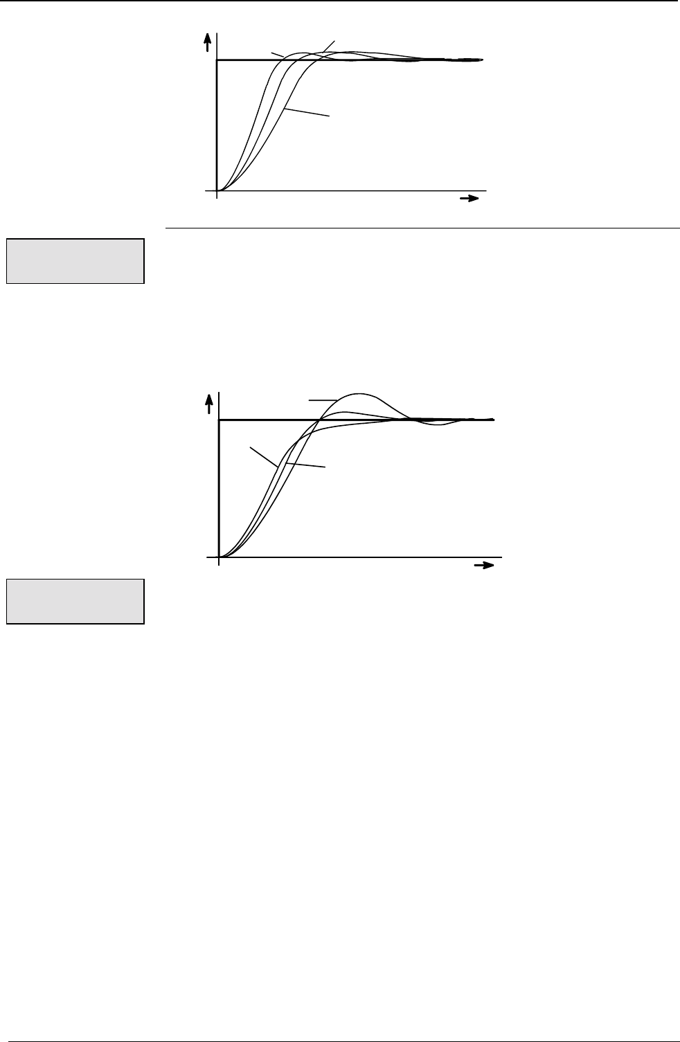
Operating Instructions COMPAX-M / -S
Optimization parameters
128
P23>100% P23=100%
P23<100%
t
speed
reference
value,
actual
value
Damping influences the height of the harmonies and reduces the vibrations.
Nominal value: 100% Range: 0%...500%
Harmonies become smaller. The drive vibrates at high frequency from a specific
value.
The harmonies of the actual value increase and it vibrates longer around the
nominal value. The drive vibrates permanently from a specific value.
P24>100%
P24=100%
P24<100%
t
speed
reference
value,
actual
value
P56: D section rpm controller
Nominal value: 0 Range: 0%...500%
The D section should generally be set for elastically coupled double mass systems.
These are systems in which the connection between the motor and the load is not
rigid. It must be noted here, that with sufficiently high torques being transmitted,
even supposedly rigid connections can become elastic.
P57: Lag D section rpm controller
Nominal value: 100% Range: 0%...550%
P58: Lag rpm filter
Nominal value: 100% Range: 0%...550%
Use this parameter to adapt the controller to very large changes in load.
Nominal value: 100% Range: 10%...500%
COMPAX is informed of the relative change in moment of inertia which occurs
before a change in load when the motor is idle (e.g. via the RS232 interface).
The nominal value (100%) corresponds to the value calculated by parameters P81
to P92.
After changing P27, P23 usually needs modification P23 in order to achieve
optimal control results.
Main effect:
P24: damping of
drive
Increase damping
Reduce damping
Main effect:
P56: D section
rpm controller
P57: Lag D
section rpm
controller
P58: Lag rpm
filter
P27: moment of
inertia
Note:
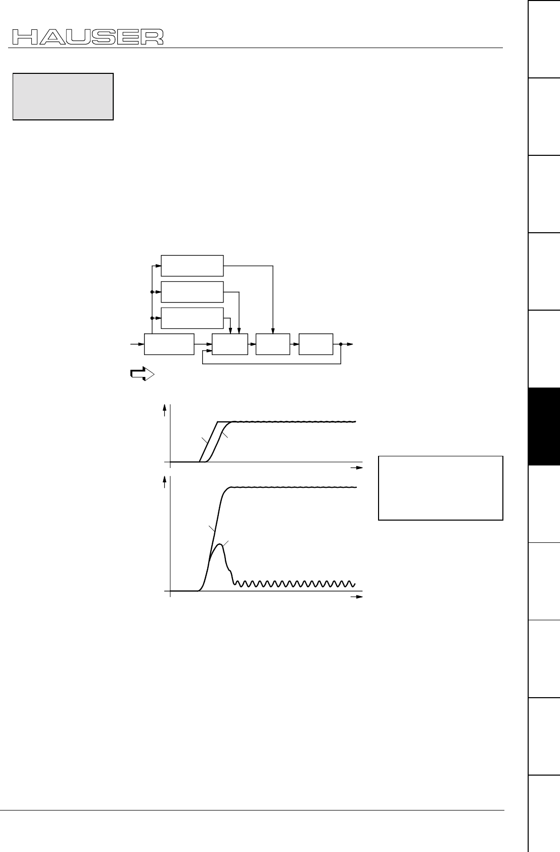
Optimization functions
Optimization parameters
129
Unit
hardware
Connector
assignment / cable
Technical dataConfigurationPositioning and
control functions
Optimization
functions
InterfacesAccessories /
options
StatusParameterError list
Advance control of speed, acceleration and power
♦
Minimum lag error
♦
Better attenuation characteristics
♦
Higher dynamic levels with lower maximum current
The positioning process is calculated in the nominal value setter and is specified to
the position controller as the nominal value. This ensures that the nominal value
setter contains the advance information required for positioning: speed,
acceleration and power processes. This information is switched to the controller so
the lag error is reduced to a minimum, the controller has better attenuation
characteristics and drive dynamics are increased.
current
feed forward
acceleration
feed forward
speed
feed forward
target
posi-
tion reference point
target
position
control
speed
control
position
integrator
position
actual
value
The stability of the control process is not influenced by the advance control
measures.
Reference
value,
actual
value
t
Driving
fault,
current
t
12
4
3
Advance
control
measures
Advantages:
Principle:
Main structure:
Without advance
control measures:
1: Nominal speed value
2: Actual speed value
3: Motor power
4: Lag error
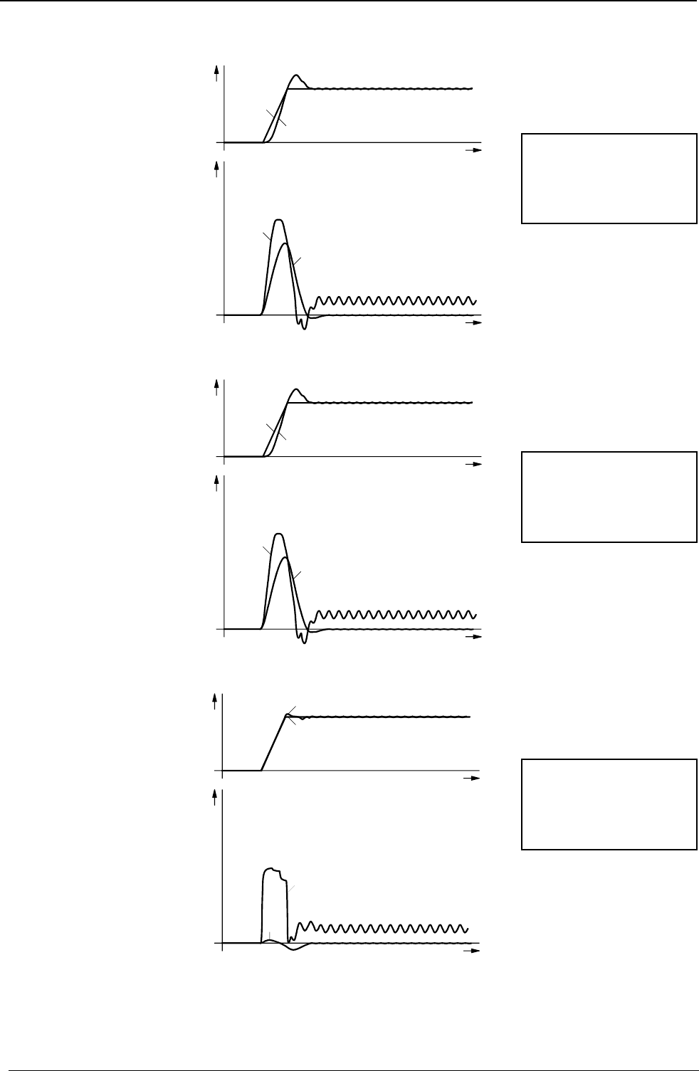
Operating Instructions COMPAX-M / -S
Optimization parameters
130
Advance speed control
Nominal value: 100% Range: 0%...500%
t
Driving
fault,
current
t
1
2
3
4
reference
value,
actual
value
Advance speed and acceleration control
Nominal value: 100% Range: 0%...500%
t
Driving
fault,
current
t
1
2
3
4
reference
value,
actual
value
Advance speed, acceleration and power control
Nominal value: 100% Range: 0%...500%
t
Driving
fault,
current
t
2
1
3
4
reference
value,
actual
value
The advance reverse control can be engaged to increase optimization of guide
characteristics and reduce dynamic lag error by using P69. Nominal value: 100%
Range: 0 ... 500% default value: 0; applies to VP
P25: Advance
speed control:
P26: Advance
acceleration
control
P70: Advance
power control
Advance reverse
control
1: Nominal speed value
2: Actual speed value
3: Motor power
4: Lag error
1: Nominal speed value
2: Actual speed value
3: Motor power
4: Lag error
1: Nominal speed value
2: Actual speed value
3: Motor power
4: Lag error

Optimization functions
Optimization parameters
131
Unit
hardware
Connector
assignment / cable
Technical dataConfigurationPositioning and
control functions
Optimization
functions
InterfacesAccessories /
options
StatusParameterError list
Control processes for optimization
Targets / problems Stiff-
ness
(P23)
Damp-
ing (P24) Advance contr.
factors (P25,
P26, P70)
Acceleration
time
(ACCEL)
Ramp
shape
(P94)
Other
measures
Minimizing lag error increase - =100%
optimize if
necessary
increase - -
No harmonies - increase decrease increase quadratic
(P94="3")
increase max.
torque (P16)
Unusually high
harmonies caused
by power limitation
decrease decrease decrease increase linear
(P94="1")
increase max.
torque (P16)
Vibrating at higher
frequencies
(perceptible as noise)
decrease decrease - - - check min. mass
(P92) and min.
moment of inertia
(P81).
Vibrating at lower
frequencies
(perceptible as
motion)
- increase - - - check max. mass
(P88) and max.
moment of inertia
(P82).
High motor or final
stage temperatures
decrease - - increase linear
(P94="1")
decrease max.
torque (P16)

Operating Instructions COMPAX-M / -S
Speed monitor
132
8.5.2 Speed monitor
In COMPAX the drive speed is required as an actual value for speed control (loop
underlying the position control).
The actual speed value is derived by differentiating the position signal.
In certain applications, such as with large ratios Jload/Jmotor, the loop response time
is limited by quantization noise.
COMPAX includes a speed monitor for determining speed, which can be turned on
using parameter P50.
Use the speed monitor to set a higher level of stiffness corresponding to a faster
control process.
The monitor reproduces the dynamic behavior of the drive. It receives the same
input signal as the physical drive. An additional loop is used to compare the output
magnitude with the actual output magnitude of the drive (actual position value from
resolver) and hold it at the same value. This additional loop makes corrections to
the internal monitor values.
The advantage is that the speed is available directly as an intermediate value of
the monitor and can be used for speed control.
Use this speed signal to attain a stable control process or to operate the drive
control process with higher levels of stiffness (P23) and the same levels of
damping.
P50=100: without monitor (default setting and function as before)
P50=101: with monitor
P151: responsiveness of the monitor control (standard 30%)
P151>30%: monitor loop becomes faster
P151<30%: monitor loop becomes slower
• For large ratios Jload/Jmotor.
Note! Do not use the speed monitor when operating
asynchronous motors.
Speed
determination
standard:
Speed monitor:
Function:
Settings:
Using the speed
monitor
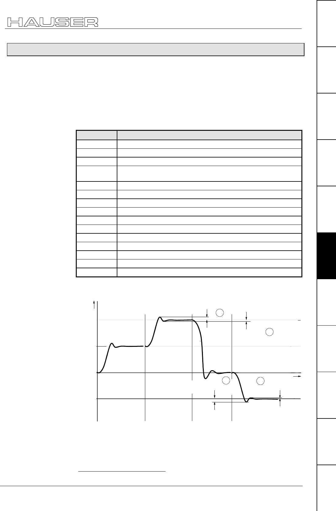
Optimization functions
Optimization display
133
Unit
hardware
Connector
assignment / cable
Technical dataConfigurationPositioning and
control functions
Optimization
functions
InterfacesAccessories /
options
StatusParameterError list
8.5.3 Optimization display
The optimization display (status S13 and S14) is an aid for optimizing COMPAX
without the need for an additional visual aid. It provides access to the characteristic
parameters of the positioning process (optimization parameters).
From a selection of 14 different parameters for the positioning process, you can
assign 2 parameters to the status values S13 and S14 by using the parameters
P233 (S13) and P234 (S14).
The optimization parameters are reset before each new positioning process and
they are continually updated during the positioning process.
P233/P23430 Meaning
1 Positioning time (from start of positioning to "Position reached")
2 max. intermediate circuit voltage in [V]
3 reserved
4 max. undershoot referenced to max. position (amount) (only for
highly shifted loops)
5 max. position overshoot [units corresp. P90] (amount)
6 max. position undershoot [units corresp. P90] (amount)
7 max. acceleration lag error [units corresp. P90]
8 max. braking lag error [units corresp. P90]
9 max. acceleration speed in [%] of motor nominal speed
10 max. braking speed in [%] of motor nominal speed
11 max. acceleration current in [%] of motor nominal current
12 max. braking current in [%] of motor nominal current
13 max. time in current limit for acceleration, in [ms]
14 max. time in current limit for braking, in [ms]
56 square of peak motor current (reference value: 80 000A2)
Enter the corresponding number in the first column in the parameter. This means
♦
P233 determines status S13 !P234 determines status S14
positive sense
of rotation
negative sense
of rotation
negative sense
of rotation
max.
position overshoot
max.
position undershoot
max position overshoot
max.
position undershoot
positive sense
of rotation
50
25
0
-25
position
time
5
5
6
6
30 P233/P234 are set as valid with VP
Optimization
parameters:
Description of
optimization
parameters
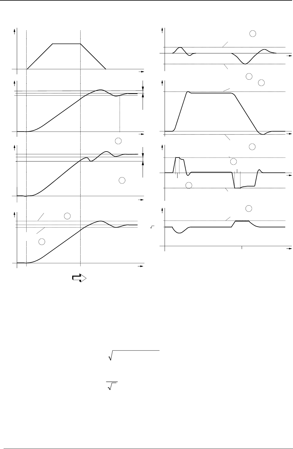
Operating Instructions COMPAX-M / -S
Optimization display
134
x
t
x
x
t
acceleration phase decerleration phase
speed
set
point
actual
value
of
position
time needed for positioning
actual
value
of
position max. backshoot with
ref. to max. position
actual
value
of
position
max. position overshoot
1
4
5
6
max. position overshoot
P14
t
t
x
t
t
t
t
7
8
9
10
13
14
2
xb
n
Iq
max. acceleration tracking error
max. acceleration speed
pos. current limit
time in pos. current limit
neg. current limit
time in neg. current limit
max. deceleration tracking error
max. deceleration speed
U
ZW
2.Umain
max. intermediate voltage
You will find a complete status list on Page207.
Reference value: 80 000A2
The maximum peak current of a motor phase is continually determined once
COMPAX is switched on and this is stored as status S13 or S14 using
P233/234=56.
This display is generated as long as the motor is powered. The value is reset when
COMPAX is switched off (after "OFF").
Obtaining the peak motor current using S13 (P233=56) as an example:
2
max A00080*13SI =
Use the effective value
II
eff =max
2
to calculate the peak load within the motor cycle.
If this value rises to 1.5 times the peak current of the system, error E41 is triggered.
You will find more detailed explanations on the limiting characteristics of COMPAX
on Page 222.
Square of peak
motor current
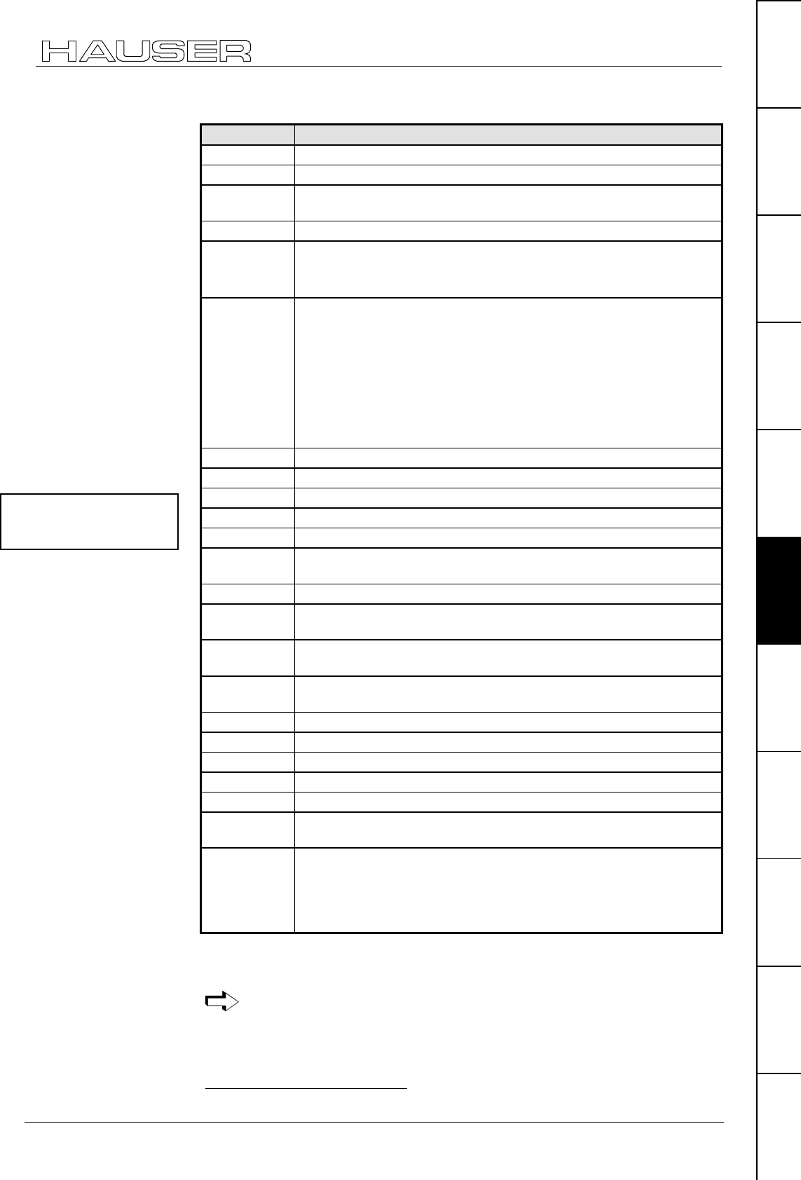
Optimization functions
Optimization display
135
Unit
hardware
Connector
assignment / cable
Technical dataConfigurationPositioning and
control functions
Optimization
functions
InterfacesAccessories /
options
StatusParameterError list
Access to additional parameters via S13 and S14:
P233/P234 Meaning
15 Current number of HEDA transmission errors
16 Average no. of HEDA transmission errors per second
17 Total number of HEDA transmission errors since beginning of
synchronization
18 Process nominal value received via HEDA
19 HEDA control word
Bit 331: Transmission error COMPAX -> IPM
Bit 8: fast start via HEDA
20 HEDA status word
Bit 0="1": no errors (corresponds to COMPAX output O1)
Bit 1="1": no warnings (corresponds to COMPAX output O2)
Bit 3="1": transmission error IPM -> COMPAX
Bit 8="1": COMPAX lag warning (="1" - in position, i.e. within lag
warning window)
Bit 9="1": HEDA interface active (COMPAX synchronized)
Default setting: Bit 0="1", Bit 1="1", Bit 3="0", Bit 8="1", Bit 9="1":
S13/S14=771
21 CPX X50 max. pos. synchronous lag error [units corresp. P90]
22 CPX X50 max. neg. synchronous lag error [units corresp. P90]
23 Output value of D/A monitor channel 0 (10V corresponds to 1)
24 Output value of D/A monitor channel 1 (10V corresponds to 1)
25 Output value of service D/A monitor channel 2 (10V corresp. to 1)
26 Output value of service – D/A monitor channel 3 (10V corresp. to
1)
27 External encoder position (units corresp. P90)
28 Measuring error (Difference between resolver position and external
encoder position in the unit corresponding to P90)
29 Effective motor load in % of the permitted continuous motor load
(E53 is indicated from 100%)
30 Effective unit load in % of the permitted continuous unit load (E53
is indicated from 100%)
31 Mark synchronization function indicator (COMPAX XX70)
32 "Scaled correction factor" (COMPAX XX70)
33 "Cycle counter" (COMPAX XX70)
35 Digital inputs I1-I16
36 Status S16 (bits 16...23) and digital outputs O1-O16 (bits 0...15)
37 Encoder frequency channel 4 in incr./ms" (COMPAX XX60,
COMPAX XX7X)
39 Cause of calculation error E07
0 Invalid Operator
1 Division by 0
2Overflow
3 Underflow
The corresponding number in the first column should be entered in the parameter.
This means
♦
P233 determines status S13 !P234 determines status S14
You will find additional special diagnosis values on Page 210.
31 Bit counting begins with 0.
You will find the meanings
of the DA monitor values on
Page 52.

Operating Instructions COMPAX-M / -S
External position localization with position adjustment
136
8.5.4 External position localization with position adjustment
The external position localization with position adjustment described below is only
available in the standard unit (COMPAX XX00). Solutions adapted to specific
applications are available in the unit variants.
A slip between motor position and the position of the drive (e.g. a material feed) is
not detected. If the slip is too large, the external position can be entered(e.g.
recorded by a measuring wheel) using encoder channel 1. In this way, COMPAX
corrects the internal actual position value.
To limit access to the position adjustment, use P36 to limit the speed correction
value resulting from the difference in positions.
This can be especially useful in the acceleration phase, if the material is slipping
through because of the higher correction speed.
To avoid all inaccuracies during internal calculations, it is important to use the
measuring unit "Increments".
Para-
meter Meaning valid
from..
P75 Maximum permitted measuring error (difference between resolver
position and encoder position)
The external position adjustment is enabled using measuring
error P75 > 0.
When P75 is reached, error E15 is generated and the drive is
switched off.
Control position adjustment via digital input I11
If the external position measurement and position adjustment
(P75>0) is switched off, position adjustment operation can be
switched on and off using input I11. For this, assign I11 with this
function via P232=4.
I11="0": External position adjustment switched off (reaction time
approx. 5 ms).
I11="1": External position adjustment switched on.
P232 becomes effective immediately and has a default value of 0.
If P232=0, I11 will not have an effect on the position adjustment;
this is then switched on and off using P75.
Note! If P232=4 (activated I11), I11 can no longer be used for
GOTO / GOSUB EXT.
VP
P36 Limitation of speed correction value for external position
adjustment (only available in COMPAX XX00 and COMPAX XX30)
"0": switched off (default value)
When P36=0, the speed correction value is not limited.
P36 is specified in % of the nominal speed (P104).
Note! When position localization is switched off, P36 must = 0!
VP
P144 Sets encoder channel 1
="4": without external position localization
="6": external position localization switched on via channel 1.
VC
P143 Number of encoder pulses per encoder rotation from channel 1;
range: 120...2 000 000.
VC
P98 Travel of load per encoder rotation units (corresp. to P90). VC
Only available in
COMPAX XX00!
Recommendation:
Configuring the
external position
adjustment:
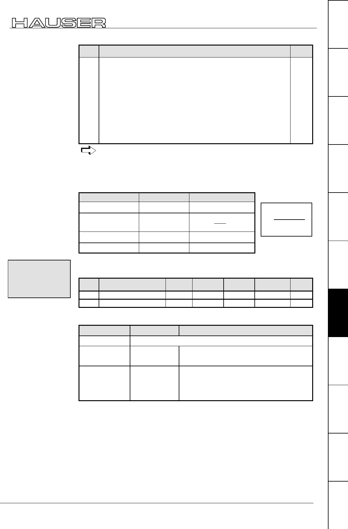
Optimization functions
External position localization with position adjustment
137
Unit
hardware
Connector
assignment / cable
Technical dataConfigurationPositioning and
control functions
Optimization
functions
InterfacesAccessories /
options
StatusParameterError list
Para-
meter Meaning valid
from..
P214 Encoder direction.
="0": positive direction for encoder rotating clockwise.
="1": positive direction for encoder rotating anti-clockwise.
Setting aid:
♦
Switch off external position adjustment (P144=4) and data record
P214=0.
♦
Note S42 (position of external sensor).
♦
Proceed with POSR x axis.
♦
S1 and S42 must change by the same value (x).
• If the prefix of the modification is different, set data record P214="1".
• If the modification has a different amount, check P143 and P98.
VP
The command "SPEED SYNC" cannot be used in external position
localization!
A number overrun is possible in special applications. To prevent this occurring, the
following condition must be met: V ≥
≥≥
≥ 1
Determine V depending on drive type and measuring unit:
Drive type Measuring unit Determining V
Spindle drive mm (inch) )4.25(85PKV ••=
Rack-and-pinion/
toothed belt
mm (inch) )4.25(
82P
85P
KV ••=
General drive mm (inch) )4.25(1000KV ••=
General drive Incr. VK=
A slip filter with a differentiating element (D-element) is provided to optimize
external position adjustment.
No. Meaning Unit Minimum
value Default
value Maximum
value Valid
from...
P67 D-element slip filter % 0100 500 VP
P68 Slip filter lag % 0100 5000 VP
Both parameters are set to 100% as standard. The time constants are then
identical and the filter ineffective. Meaning:
Parameter Effect Application
P67 = P68 Filter ineffective (standard)
P67 < P68 or
P67 = 0
Filter has
delaying effect
♦
Low resolution of measuring system
♦
Interference on the measuring signal
P67 > P68 Filter has
differentiating
effect
at high dynamic requirements.
Conditions: high-resolution measuring
system and low interference on the measuring
signal.
Limit values of
parameters
Slip filter for
external
position
localization
Using
KP
PP
=•
•
98 16384
83 143 .
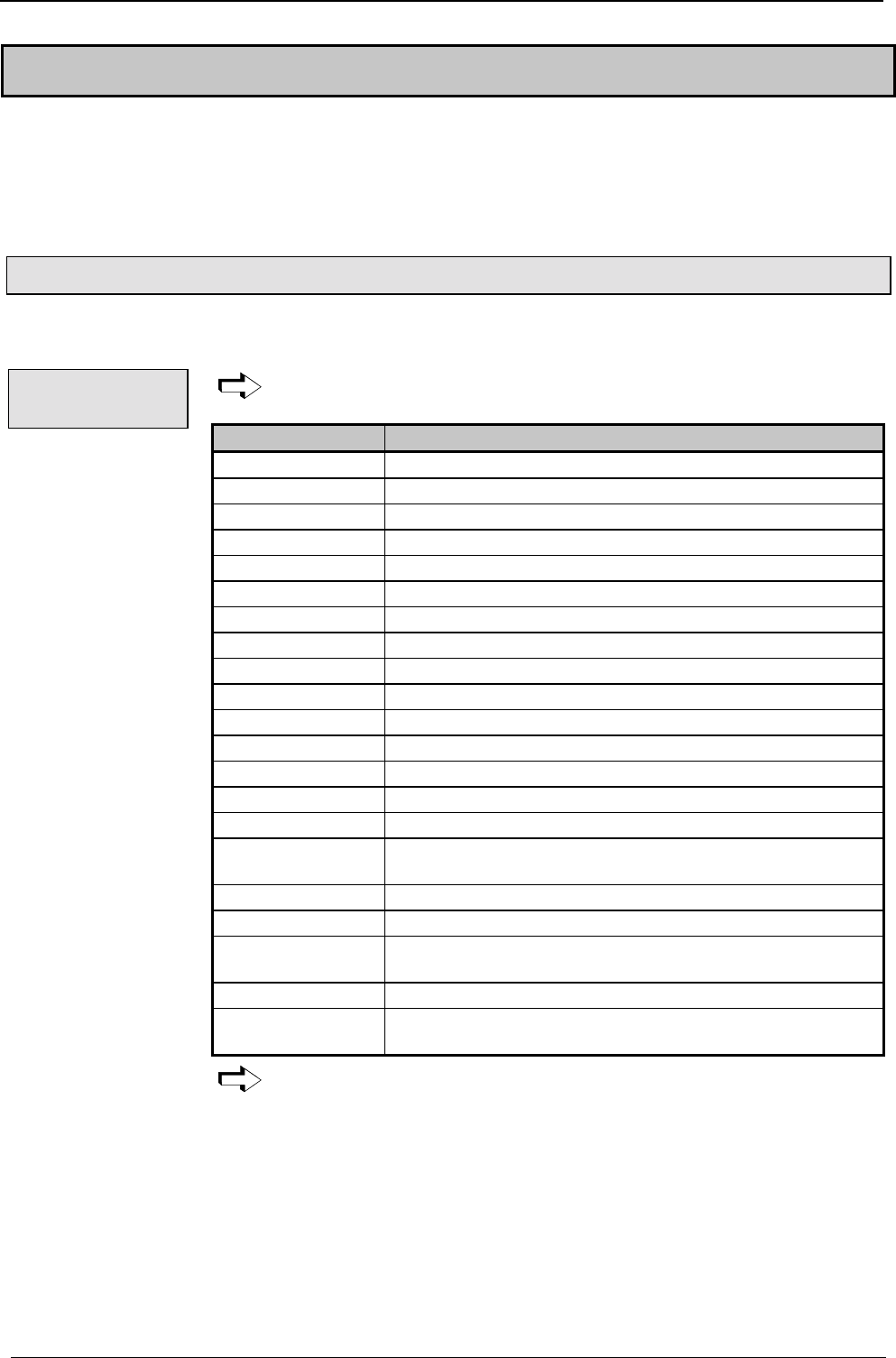
Operating Instructions COMPAX-M / -S
Digital inputs and outputs
138
8.6 Interfaces
The COMPAX interfaces for data and status are digital inputs with an PLC data
interface, an RS232 interface and an optional bus interface (interbus S, CAN bus,
CANopen, profibus, CS31 or RS485).
The RS232 interface can be operated simultaneously with other interfaces.
8.6.1 Digital inputs and outputs
To control the program process, 16 inputs and 16 outputs are available (8 inputs
and 8 outputs with COMPAX 1000SL).
O7-O11 and I7-I11 are assigned when the PLC data interface is switched
on.
Input Assignment
I1 (X8/1; X19/x) SHIFT
I2 (X8/2; X19/x) Manual+
I3 (X8/3; X19/x) Hand–
I4 (X8/4; X19/x) Quit
I5 (X8/5; X19/x) START
I6 (X8/6; X19/x) Stop (interrupts data record)
I7 (X8/7; X19/x) Freely assignable in the standard unit.
I8 (X8/8; X19/x) Freely assignable in the standard unit.
SHIFT I2 Find machine zero (MZ)
SHIFT I3 Approach real zero (RZ)
SHIFT I4 Teach real zero
SHIFT I5 reserved
SHIFT I6 Break (breaks off data record)
I9 (X10/1; X19/x) Freely assignable in the standard unit.
I10 (X10/2; X19/x) Freely assignable in the standard unit.
I11 (X10/3; X19/x) Assigned when P232=4 (activates position adjustment);
otherwise free.
I12 (X10/4; X19/x) Freely assignable in the standard unit.
I13 (X10/5; X19/x) Freely assignable in the standard unit.
I14 (X10/6; X19/x) Assigned when mark reference is activated (P35=1)
(activates mark reference); otherwise free.
I15 (X10/7; X19/x) Fast start (can be activated using P18)
I16 (X10/8; X19/x) Is assigned if mark reference is activated (P35=1) (mark
input); otherwise free.
The assignment of inputs on X19 applies only to COMPAX 1000SL.
I/O - assignment
of standard unit
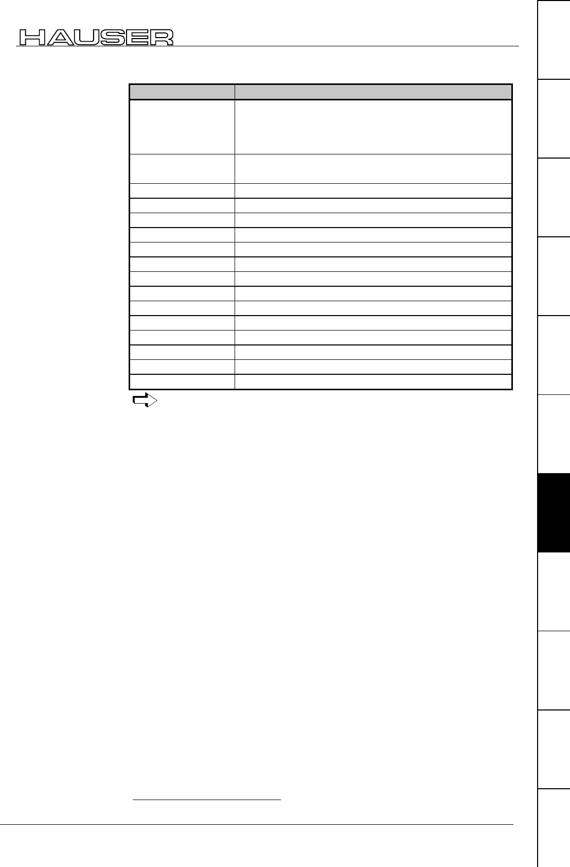
Interfaces
Digital inputs and outputs
139
Unit
hardware
Connector
assignment / cable
Technical dataConfigurationPositioning and
control functions
Optimization
functions
InterfacesAccessories /
options
StatusParameterError list
Output Assignment
O1 (X8/9; X19/x) ="1":No fault
="0":errors E1 ... E58; the drive does not accept any
positioning commands.
After "Power on" O1 remains at "0" until after the self test.
O2 (X8/10; X19/x) ="1":No warning
="0":error ≥ E58
O3 (X8/11; X19/x) Machine zero has been approached
O4 (X8/12; X19/x) Ready for start
O5 (X8/13; X19/x) Programmed nominal position reached
O6 (X8/14; X19/x) Idle after stop
O7 (X8/15; X19/x) Freely assignable in the standard unit.
O8 (X8/16; X19/x) Freely assignable in the standard unit.
O9 (X10/9; X19/x) Freely assignable in the standard unit.
O10 (X10/10; X19/x) Freely assignable in the standard unit.
O11 (X10/11; X19/x) Freely assignable in the standard unit.
O12 (X10/12; X19/x) Freely assignable in the standard unit.
O13 (X10/13; X19/x) Freely assignable in the standard unit.
O14 (X10/14; X19/x) Freely assignable in the standard unit.
O15 (X10/15; X19/x) Freely assignable in the standard unit.
O16 (X10/16; X19/x) For "0": mark disappears after max. feed length32
The assignment of outputs on X19 applies only to COMPAX 1000SL.
32 Only assigned if the mark reference is activated (P35=1).
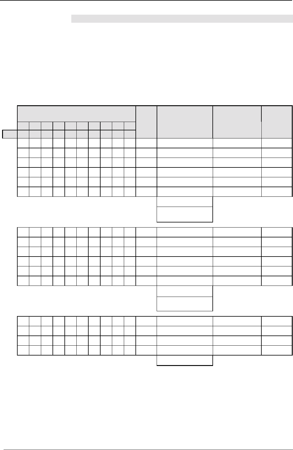
Operating Instructions COMPAX-M / -S
Digital inputs and outputs
140
8.6.1.1 Digital inputs and outputs for COMPAX 1000SL
Allocation of logic inputs for input pins of X19
The source (input pin on X19) from which the respective logic input is to be read is
specified via parameters P156, P157 and P158. Inputs which are not read by an
input pin on X19 can be allocated a fixed "0" or "1 (this is not, of course, applicable
for all inputs). The parameters are 24 bits large with 4 bits defined per logic input.
This allocation can be easily done with the assistance of the ServoManager.
With direct access via RS232, a terminal or a fieldbus, the following table can be
used for setting the parameters.
Source
fixed logical value (0 or 1) or pin of X19
=0 =1 /2 /3 /4 /5 /6 /7 /8 /9
Value: 0123456789
factor computed values Allocation:
Input reads from
which source
Logical
inputs
1Value * factor P156 bit 0...3 Input 1
16 +Value * factor P156 bit 4...7 Input 2
256 +Value * factor P156 bit 8...11 Input 3
4096 +Value * factor P156 bit 12...15 Input 4
65536 +Value * factor P156 bit 16...19 Input 5
1048576 +Value * factor P156 Bit 20...23 Input 6
ΣTotal
Value of P156:
♦ Total ≤
≤≤
≤ 8 388 607:
P156 = Total
♦ Total > 8 388 607:
P156 = Total – 16 777 216
1Value * factor P157 bit 0...3 Input 7
16 +Value * factor P157 bit 4...7 Input 8
256 +Value * factor P157 bit 8...11 Input 9
4096 +Value * factor P157 bit 12...15 Input10
65536 +Value * factor P157 bit 16...19 Input 11
1048576 +Value * factor P157 Bit 20...23 Input 12
ΣTotal
Value of P157:
♦ Total ≤
≤≤
≤ 8 388 607:
P156 = Total
♦ Total > 8 388 607:
P156 = Total – 16 777 216
1Value * factor P158 bit 0...3 Input 13
16 +Value * factor P158 bit 4...7 Input 14
256 +Value * factor P158 bit 8...11 Input 15
4096 +Value * factor P158 bit 12...15 Input 16
Value of P158: Σ
Note that only one selection can be made per line, i.e. only one cross is permitted!
Note
Allocation table:
Logical input is read by
X19 pin ...
Allocation table:
Logical input is read by
X19 pin ...
Allocation table:
Logical input is read by
X19 pin ...
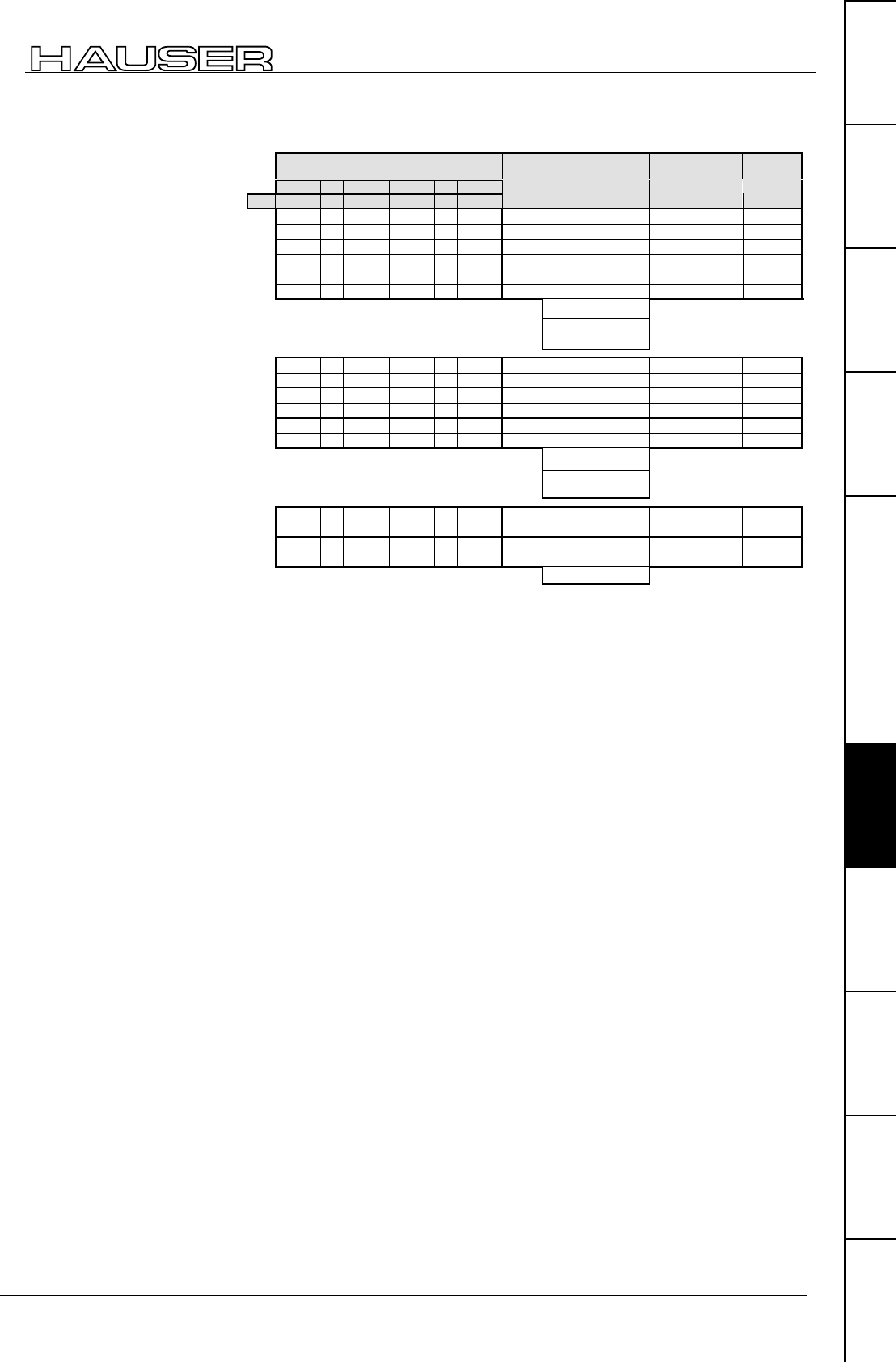
Interfaces
Digital inputs and outputs
141
Unit
hardware
Connector
assignment / cable
Technical dataConfigurationPositioning and
control functions
Optimization
functions
InterfacesAccessories /
options
StatusParameterError list
Example:
The following
assignment must be
configured:
"0" → input 1
X19 pin 3 → input 2
X19 pin 4 → input 3
X19 pin 5 → input 4
X19 pin 6 → input 5
X19 pin 7 → input 6
"0" → input 7
"0" → input 8
"0" → input 9
"0" → input 10
"0" → input 11
X19 pin 8 → input 12
X19 pin 2 → input 13
"1" → input 14
"0" → input 15
X19 pin 9 → input 16
The remaining inputs stay open and are therefore not imported.
You can see the calculation of the setting values on the right.
Note
♦
It is in principle possible to read 2 inputs from the same input pin. Of course note
should be taken of the resulting function.
♦
If you do not need the enable input I12, fixed logic "1" can be allocated.
♦
With P233=49 (or P234=49), physical inputs pin 9 – pin 2 are written to the
optimization display status S13 (S14). Meaning: pin 2 = bit 0 ... pin 9 = bit 7.
Source
fixed logical value (0 or 1) or pin of X19
=0 =1 /2 /3 /4 /5 /6 /7 /8 /9
Wert: 0 1 2 3 4 5 6 7 8 9
factor computed values Allocation:
Input reads from
which source
Logical
inputs
X10*1=0 P156 bit 0...3 Input 1
x16 +3*16=48 P156 bit 4...7 Input 2
x256 +4*256=1024 P156 bit 8...11 Input 3
x4096 +5*4096=20480 P156 bit 12...15 Input 4
x65536 +6*65536= 393216 P156 bit 16...19 Input 5
x1048576 +7*1048576=7340032 P156 bit 20...23 Input 6
Σ7 754 800
Value of P156: 7 754 800
♦ Total ≤
≤≤
≤ 8 388 607
P156 = Total
♦ Total > 8 388 607
P156 = Total – 16 777 216
x10*1=0 P157 bit 0...3 Input 7
x16 +0*16=0 P157 bit 4...7 Input 8
x256 +0*256=0 P157 bit 8...11 Input 9
x4096 +0*4096=0 P157 bit 12...15 Input 10
x65536 +0*65536=0 P157 bit 16...19 Input 11
x1048576 +8*1048576=8388608 P157 bit 20...23 Input 12
Σ8 388 608
Value of P157: -8 388 608
♦ Total ≤
≤≤
≤ 8 388 607
P156 = Total
♦ Total > 8 388 607
P156 = Total – 16 777 216
x12*1=2 P158 bit 0...3 Input 13
x16 +1*16=16 P158 bit 4...7 Input 14
x256 +0*256=0 P158 bit 8...11 Input 15
x4096 +9*4096=36 864 P158 bit 12...15 Input 16
Value of P158: Σ36 882
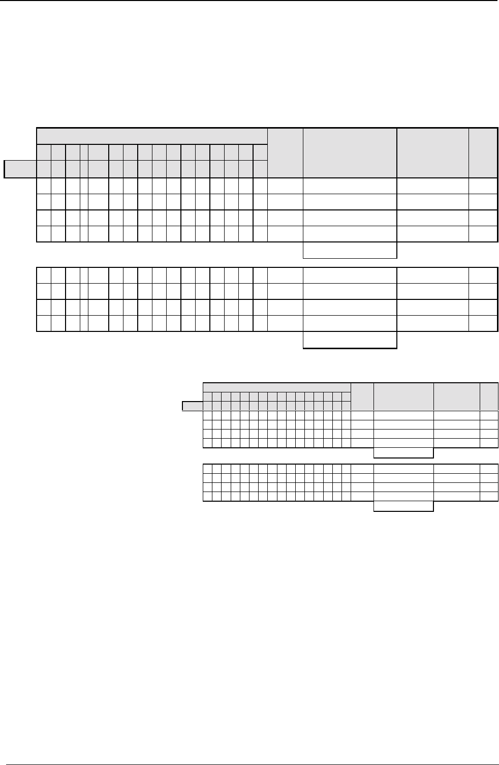
Operating Instructions COMPAX-M / -S
Digital inputs and outputs
142
Allocation of output pins of X19 to the logic outputs
The target (output pin on X19) on which the respective logic output is to be written
is specified via parameters P159 and P160. The parameters are 24 bits large with
4 bits defined for allocating each output to an output pin
This allocation can be easily done with the assistance of the ServoManager.
With direct access via RS232, a terminal or a fieldbus, the following table can be
used for setting the parameters.
Outputs
2 3 4 5 6 7 8 9 10 11 12 13 14 15 16
value: 0 1 2 3 4 5 6 7 8 9 10 11 12 13 14 15
factor computed values Allocation:
output is
assigned to pin
X
X19
Outp
ut
Pin
1Value * factor P159 bit 0...3 /15
16 +Value * factor P159 bit 4...7 /16
256 +Value * factor P159 bit 8...11 /17
4096 +Value * factor P159 bit 15...11 /18
Value of P159:
Σ
1Value * factor P160 bit 0...3 /19
16 +Value * factor P160 bit 4...7 /20
256 +Value * factor P160 bit 8...11 /21
4096 +Value * factor P160 bit 11...15 /22
Value of P160:
Σ
Example:
The following assignment must be configured:
Output 1 → X19 Pin 15
Output 3 → X19 Pin 16
Output 4 → X19 Pin 17
Output 5 → X19 Pin 18
Output 8 → X19 Pin 19
Output 10 → X19 Pin 20
Output 14 → X19 Pin 21
Output 16 → X19 Pin 22
You can see the calculation of the
setting values on the right.
Note
♦
With P233=49 (or P234=49 respectively) physical outputs pin 22 – pin 15 are
written to the optimization display status S13 (S14). Meaning: pin 15 = bit 8 ...
pin 22 = bit 15.
Allocation table:
output is assigned ... to
pin X19
Allocation table:
output is assigned ... to
pin X19
Outputs
1 2 3 4 5 6 7 8 9 10 11 12 13 14 15 16
Value: 0 1 2 3 4 5 6 7 8 9 10 11 12 13 14 15
factor computed values Allocation:
output is
assigned to pin
X
X19
Out-
put
Pin
X10*1=0 P159 bit 0...3 /15
X16 +2*16=32 P159 bit 4...7 /16
X256 +3*256=768 P159 bit 8...11 /17
X4096 +4*4096=16384 P159 bit 11...15 /18
Value of P159:
Σ
17184
X17*1=7 P160 bit 0...3 /19
X16 +9*16=144 P160 bit 4...7 /20
X256 +13*256=3328 P160 bit 8...11 /21
X4096 +15*4096=61440 P160 bit 11...15 /22
Value of P160:
Σ
64919
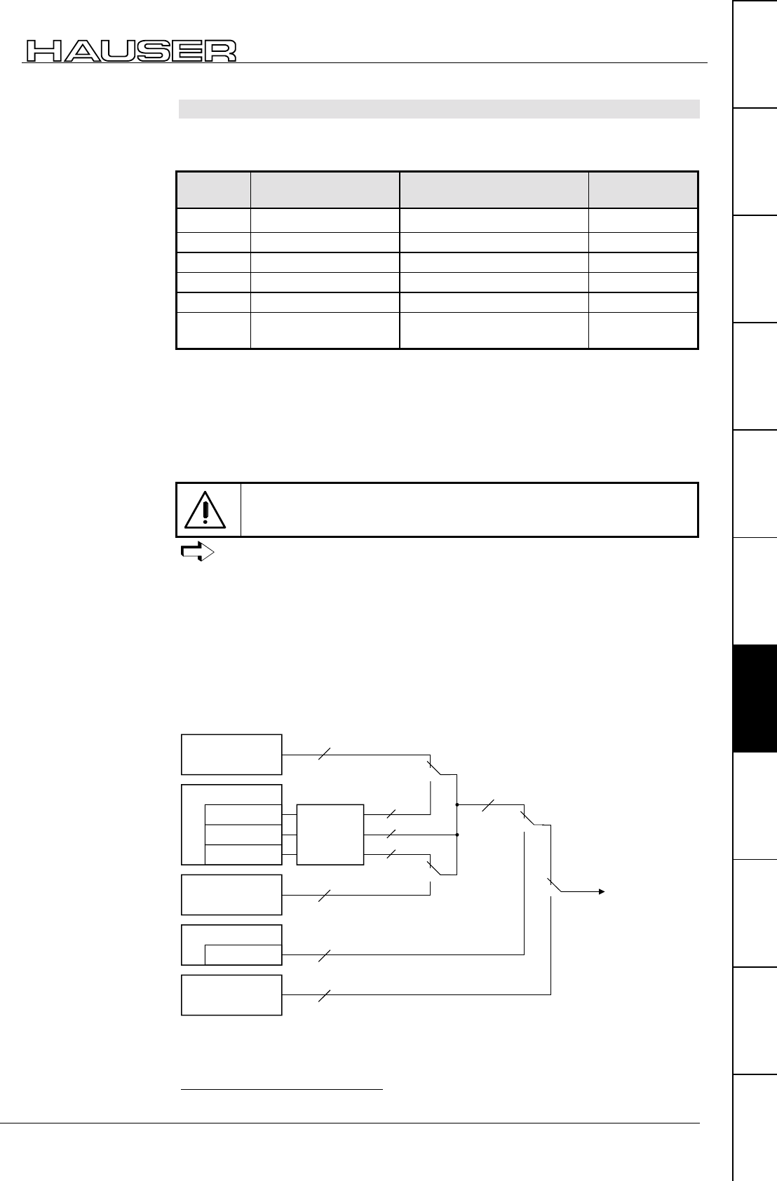
Interfaces
Digital inputs and outputs
143
Unit
hardware
Connector
assignment / cable
Technical dataConfigurationPositioning and
control functions
Optimization
functions
InterfacesAccessories /
options
StatusParameterError list
8.6.1.2 Free assignment of inputs and outputs
You can make the permanently assigned standard inputs I1 to I6 available for
assignment using parameter P221. Meaning:
Input Function without
SHIFT Function with SHIFT Valency
I1 (X8/1) SHIFT - 1(Bit 1)33
I2 (X8/2) Manual+ Find machine zero (MZ) 2(Bit 2)
I3 (X8/3) Hand– Approach real zero (RZ) 4(Bit 3)
I4 (X8/4) Quit Teach real zero 8(Bit 4)
I5 (X8/5) START reserved 16 (Bit 5)
I6 (X8/6) STOP Break (breaks off data
record) 32 (Bit 6)
Each input is assigned a valency. Calculate the sum of the valencies of the
required free inputs and enter this in parameter P221.
Hand+ and Hand- should be possible via the inputs; I1, I4, I5 and I6 should be
freely available.
1 (I1) + 8 (I4) +16 (I5) +32 (I6) = 57
You will obtain this setting using P221 = 57.
Note that when I1 is freely assigned (SHIFT), you can no longer
perform any "Functions with shift" via the inputs!
You can directly cancel all input functions (apart from Hand+ and Hand-) as
commands using interfaces (RS232, bus system).
♦
The status outputs O1 to O6 can be freely assigned using parameter P225.
♦
Use P223 and P224 to assign the outputs of the OUTPUT WORD command of
the bus systems (Interbus-S, Profibus, CAN – Bus, ...).
♦
Use P245 and P246 to assign the outputs of the HEDA bus (COMPAX with IPM
via the option A1).
♦
Permanently assigned outputs of unit variants (COMPAX XX30, ...) cannot be
masked.
RS232
Output x=y
bussystems
Output WORD
command line
bussystems
PLC data interface
HEDA via IPM
O1 ... O6
status outputs
or
≥ 1
O1 ... O6
O1 ... O6
O7 ... O11
O1 ... O16
O1 ... O16
O7 ... O11
0
0
0
1
1
1
P18
= "1" or "3"
O12 ... O16 O1 ... O16
P225
P223 /
P224
P245 /
P246
towards
outputs
33 Counting starts at 1.
Free assignment
of inputs
Setting P221
Example:
Free assignment
of outputs
Structural diagram

Operating Instructions COMPAX-M / -S
Digital inputs and outputs
144
Explanation:
The permanently assigned standard outputs O1 to O6 can be made freely
available using parameter P225. Meaning:
Output Function Valency
O1 (X8/1) ="1": No fault
="0": errors E1 ... E58 1(Bit 1)34
O2 (X8/2) ="1": No warning
="0": Error ≥ E58
2(Bit 2)
O3 (X8/3) Machine zero has been approached 4(Bit 3)
O4 (X8/4) Ready for start 8(Bit 4)
O5 (X8/5) Programmed nominal position reached 16 (Bit 5)
O6 (X8/6) Idle after stop 32 (Bit 6)
Each output is assigned a valency. Calculate the total of the valencies for the
required free outputs and enter this in parameter P225.
"Ready for start" and "Idle after stop" should be possible via the outputs; O1, O2,
O3 and O5 should be freely available.
1 (O1) + 2 (O2) +4 (O3) +16 (O5) = 23
You will obtain this setting using P225 = 23.
Using the interfaces (RS232, bus systems) and using the data record
program, the outputs can optionally (in parallel) be described using OUTPUT
Ox=y.
When the PLC data interface is activated, the outputs must not be addressed using
the interfaces (RS232, bus systems) or using the data record program.
Simultaneous operation with the OUTPUT WORD command or with HEDA is not
permitted!
P223 / P224: switching to OUTPUT WORD command
P245 / P246: switching to HEDA bus
Access to the outputs can be assigned as bits to the OUTPUT WORD command or
to HEDA. Only the enabled outputs are then described by the OUTPUT WORD
command or by HEDA.
34 Counting starts at 1.
P225: makes
outputs freely
available.
Setting P225
Example:
PLC data interface
Note!
Switching to
OUTPUT WORD
command or to
HEDA bus
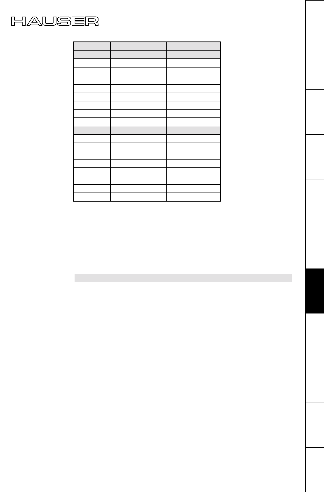
Interfaces
Digital inputs and outputs
145
Unit
hardware
Connector
assignment / cable
Technical dataConfigurationPositioning and
control functions
Optimization
functions
InterfacesAccessories /
options
StatusParameterError list
Outputs OUTPUT parallel HEDA
P223 P245
O1 1(Bit 1)35 1(Bit 1)
O2 2(Bit 2) 2(Bit 2)
O3 4(Bit 3) 4(Bit 3)
O4 8(Bit 4) 8(Bit 4)
O5 16 (Bit 5) 16 (Bit 5)
O6 32 (Bit 6) 32 (Bit 6)
O7 64 (Bit 7) 64 (Bit 7)
O8 128 (Bit 8) 128 (Bit 8)
P224 P246
O9 1(Bit 1) 1(Bit 1)
O10 2(Bit 2) 2(Bit 2)
O11 4(Bit 3) 4(Bit 3)
O12 8(Bit 4) 8(Bit 4)
O13 16 (Bit 5) 16 (Bit 5)
O14 32 (Bit 6) 32 (Bit 6)
O15 64 (Bit 7) 64 (Bit 7)
O16 128 (Bit 8) 128 (Bit 8)
Each output is assigned a valency. Calculate the total of the valencies of the
required outputs and enter this in the relevant parameter.
O4 to O16 should be influenced by the OUTPUT WORD command; O1, O2 and
O3 should be available via OUTPUT Ox=y.
8 (O4) + 16 (O5) +32 (O6) +64 (O7) +128 (O8) = 248
When P223 = 248 and P224 = 255 (total of all valencies), you will obtain this
setting.
8.6.1.3 COMPAX virtual inputs
COMPAX provides 48 logic inputs. These are divided into:
♦
inputs I1 ... I16 which are actuated via the physical inputs.
♦
virtual inputs I17 ... I32 which are activated via a fieldbus (object CPX_STW).
♦
virtual inputs I33 ... I48 which are activated via a COMPAX command (OUTPUT
O33 ... OUTPUT O48, or abbreviated: OT O33 ... OT O48).
Access to COMPAX control functions
Access to COMPAX control functions (functions which are allocated to inputs
I1...I16 by default) can be configured via parameters P221 and P222 (see
structural diagram on the right).
The allocation of the bits in P221 and P222 respectively to the relevant inputs can
be found in the parameter description)
35 Counting starts at 1.
Setting P223, P224,
P245, P246
Example:
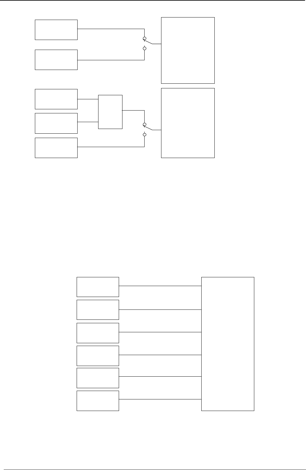
Operating Instructions COMPAX-M / -S
Digital inputs and outputs
146
Logical inputs *
I1...I8
Field bus I17...I24
Logical inputs *
I9...I16
Field bus I25...I32
≥
≥≥
≥1
="0"
P222
="1"
="0"
P221
="1"
COMPAX –
control functions
Depends on COMPAX
device variants (for
P222=”0” corresponds to
arrangement of inputsIE9
to I16)
COMPAX - control
functions
(for P221=”0”
corresponds to
arrangement of inputs I1
to I8)
SHIFT, Hand+, Hand-,
Quit, Start, Stop,
approach Mn, approach
RN, Tech RN
logical I1...I8
logical I9...I16
logical
I9...I16
COMPAX–command
I41...I48
(OTA41...OTA48)
Structural diagram: Access to
COMPAX control functions via
inputs
* The logic inputs I1 ... I16 are,
excluding COMPAX 1000SL, also
the physical inputs I1 ...I16 on
connectors X8 and X10.
With COMPAX 1000SL, the 8
physical inputs on connector X19
are allocated (via parameters P156
... P158) to 8 logic inputs from the
range I1 ... I16 (see Page 140)
Remarks regarding the structural diagram
♦
The control functions corresponding to I1.. I8 cannot be activated via OT
O33...OT O40.
♦
The control functions corresponding to I9...I16 can be activated simultaneously
via the physical inputs and via OT O41...OT O48.
♦
The enable input I12 (in COMPAX 1000SL, COMPAX XX70 and COMPAX XX30)
must also be activated when allocated to the fieldbus (via P222).
Interrogation of inputs in the COMPAX program (IF I ..)
All inputs can be interrogated independently of parameters P221 and P222 in the
COMPAX program with IF I... .
The virtual inputs I33...I48 in the COMPAX program can also be set via the
commands OT O33...OT O48.
COMPAX–command
I33...I40
(OTA33...OTA40)
COMPAX–command
I41...I48
(OTA41...OTA48)
Logical inputs *
I1...I8
Field bus I17...I24
Logical inputs *
I9...I16
Field bus I25...I32
COMPAX – program
Interrogation of inputs with
IF I1=
To
IF I48=
Regardless of parameters
P221 and P222
With P233=48 (or P234=48), virtual inputs I48 – I25 are written to the optimization
display status S13 (S14). Meaning: I25 = bit 0 ... I48 = bit 23.

Interfaces
Digital inputs and outputs
147
Unit
hardware
Connector
assignment / cable
Technical dataConfigurationPositioning and
control functions
Optimization
functions
InterfacesAccessories /
options
StatusParameterError list
8.6.1.4 I/O assignment of variants
I12: final stage enable
I13: measuring error compensation by external position measurement
I14: release brake
O14: no measuring error
O16: no power to final stage
I6: STOP ineffective during synchronization process.
I1 & I6: BREAK interrupts the synchronization process.
I12: Material simulation
I13: Manual step
I14: Switches on mark reference
I15: Ends synchronous travel
(The "Fast start" function is not possible)
I16: Mark input
O5: Position reached at synchronization command (WAIT POSA, WAIT POSR)
="0"; when the axis starts
="1": after return run.
O14: Synchronous comparator
O15: Chaff length
O16: Reject length
I14: Switches over the dimension reference
I15: Transmission factor selection
I16: Enable master nominal value
I12: Enable final stage
I13: ="0": Decoupling ="1": Coupling
I14: Mark input
I15: ="0": Disables auxiliary functions ; ="1": Enables auxiliary functions
I16: Enables master position
O7...O14: Digital auxiliary functions.
O13/O14: Cannot be used via OUTPUT.
O14: Mark not in mark window.
O15: Lag warning
O16: Synchronous run
Please refer to the instructions for the variant you are
using for up-to-date information!
COMPAX XX30:
Round table
control
COMPAX XX50:
Synchronous
cycle control
COMPAX XX60:
Electronic
transmission
COMPAX XX70:
Cam control
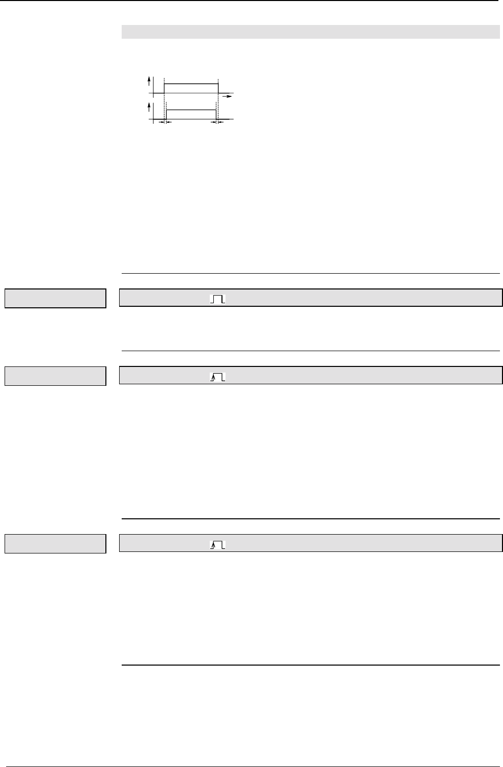
Operating Instructions COMPAX-M / -S
Digital inputs and outputs
148
8.6.1.5 Function of inputs
When working with pre-assigned inputs, always note the following:
♦
The SHIFT signal (I1) may only change if I2...I5 ="0".
t
I1
SHIFT
I2-I5
> 0,2ms > 0,2ms
♦
The "STOP" and "BREAK" functions (input I6) have top priority.
♦
For the inputs I1 to I5, only the first input present will be detected and the relevant
function activated. The other functions are then blocked; this means, e.g.:
If Quit (I4) is set during a process involving Hand+ (I2="1"), Quit is not detected
even after I2="0". A new rising flank will be required for Quit (I4).
If a program is interrupted by STOP when START is present (I5), the program is
then continued using I6="0" (STOP is deactivated).
For sure detection, the signals must be present for ≥ 1ms.
Input I1
♦
Switches to the functions for inputs I2 to I6.
♦
Signal I1 may only change if I2...I6 ="0".
Input I2/I3
♦
Processes the axis in manual mode (velocity: P5; ramp time: P9).
♦
Conditions for manual procedure:
♦
The axis must be stationary and powered.
♦
There must not be any programs running (exception: program is at WAIT
START).
♦
When the end limits are reached (P11, P12), the drive is stopped.
♦
The outputs O5 "Nominal position reached" and O4 "Ready for START" are at "0"
during manual mode; O5 remains at "0" even once manual mode has been
completed.
Input I4
♦
Acknowledges an error message or warning.
♦
If the error is rectified, O1 "No fault" or O2 "No warning" is set.
♦
The following functions are possible when there is an error present:
♦
VP, VC, VF
♦
Quit
♦
OUTPUT O0
♦
GOTO data record indicator / password
Exception: START
Length of signal ≥
≥≥
≥
1ms
SHIFT
Hand+/Hand–
QUIT
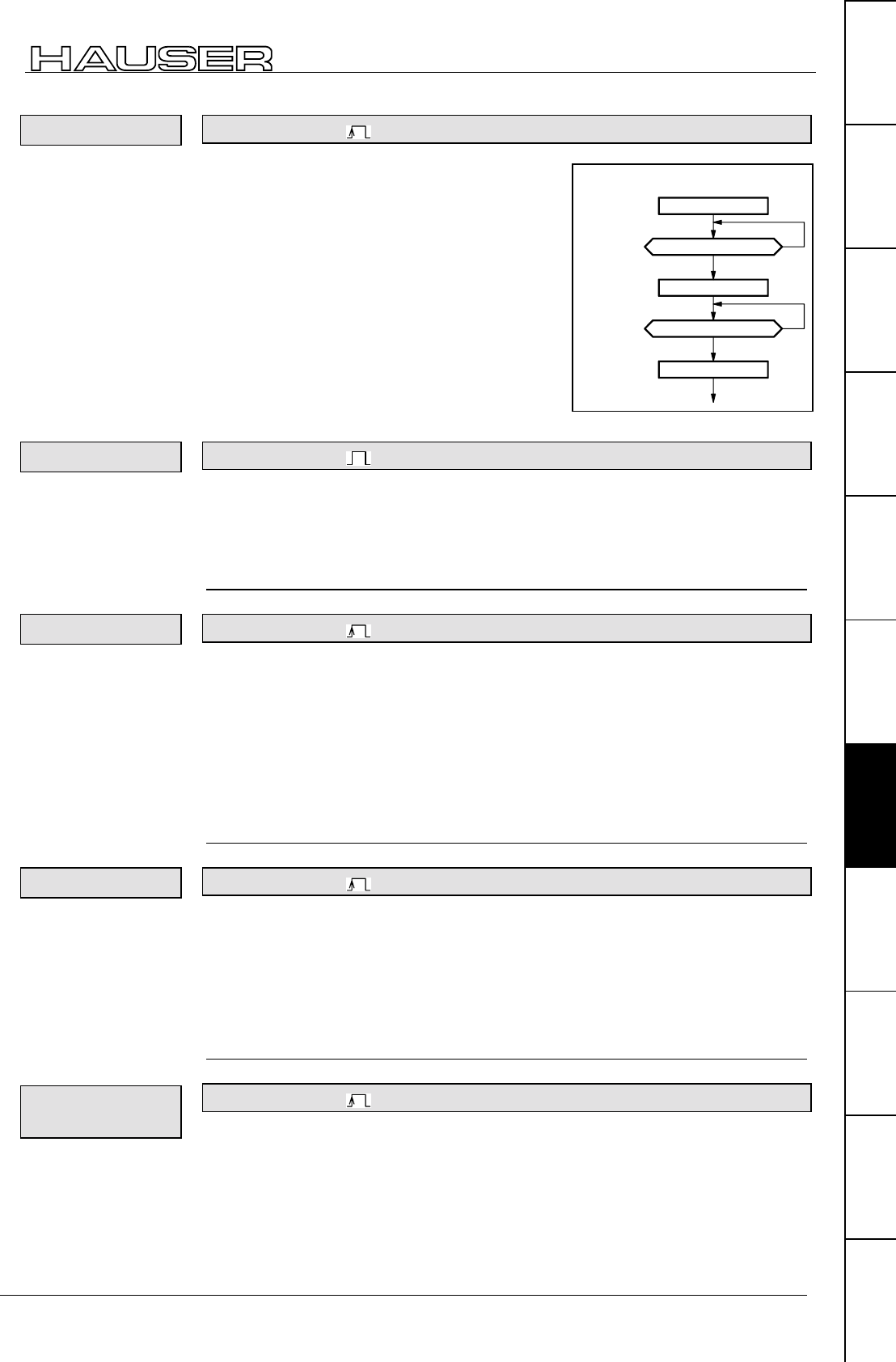
Interfaces
Digital inputs and outputs
149
Unit
hardware
Connector
assignment / cable
Technical dataConfigurationPositioning and
control functions
Optimization
functions
InterfacesAccessories /
options
StatusParameterError list
Input I5
♦
Starts the program data record at WAIT
START, after Power On and after STOP.
♦
Performs the next data records (commands)
before the next WAIT START command, an
END instruction or a STOP or BREAK signal.
♦
O4 "Ready for start" is reset.
♦
Once a positioning process has been
interrupted by STOP (I6="1"), the process can
be continued, when START (I5="1") is
present, using a descending flank at STOP
(I6="0").
Input I6
♦
The positioning process is interrupted using "1" and the axis is stopped in a
controlled manner.
♦
O4 "Ready for start" and O6 "Idle after stop" ="1".
♦
A new start command is required to complete the positioning process. When
START is present, resetting the STOP signal is sufficient (I6="0").
Input SHIFT I2
♦
Finds the machine zero point (when using reversing initiators: process velocity:
P3 - the direction of the search can be determined using the P3 sign ; ramp
time: P7).
♦
Once the MZ is reached, output O3 "Machine zero approached" is set. This
remains set until another "Find MZ" order is issued.
♦
Output O5 "Programmed position reached" ="0".
♦
The data record indicator is reset to N001.
♦
Reference travel, prompted by the digital inputs, interrupts a positioning
command specified by the interfaces (POSA, POSR, LOOP).
Input SHIFT I3
♦
The axis travels to the real zero point (process velocity: P4; ramp time: P8).
♦
O4 "Ready for start" ="0" until RZ is reached.
♦
Output O5 "Programmed position reached" ="0", and once real zero is
approached ="1".
♦
Data record indicator is reset to N001.
♦
In continuous mode the axis does not move; the data record indicator is set to
N001.
Input SHIFT I4
♦
The current position of the axis is used as the reference point (real zero) for all
positioning instructions; i.e. P1 is modified.
♦
The data record indicator is set to 1.
♦
The real zero is stored protected against power failure.
♦
O4 "Ready for start" is not modified.
♦
The teach in function can be switched off using P211.
♦
The function does not operate in continuous mode.
START
Temporal course of a start sequence:
O4 (ready for start) = "1" ?
yes
no
I5 (start signal) = "1"
O4 (ready for start) = "0" ?
I5 (start signal) = "0"
yes
no
drive to MN
Note!
STOP
Find MZ
Approach RZ
Teach in real
zero (Teach Z)
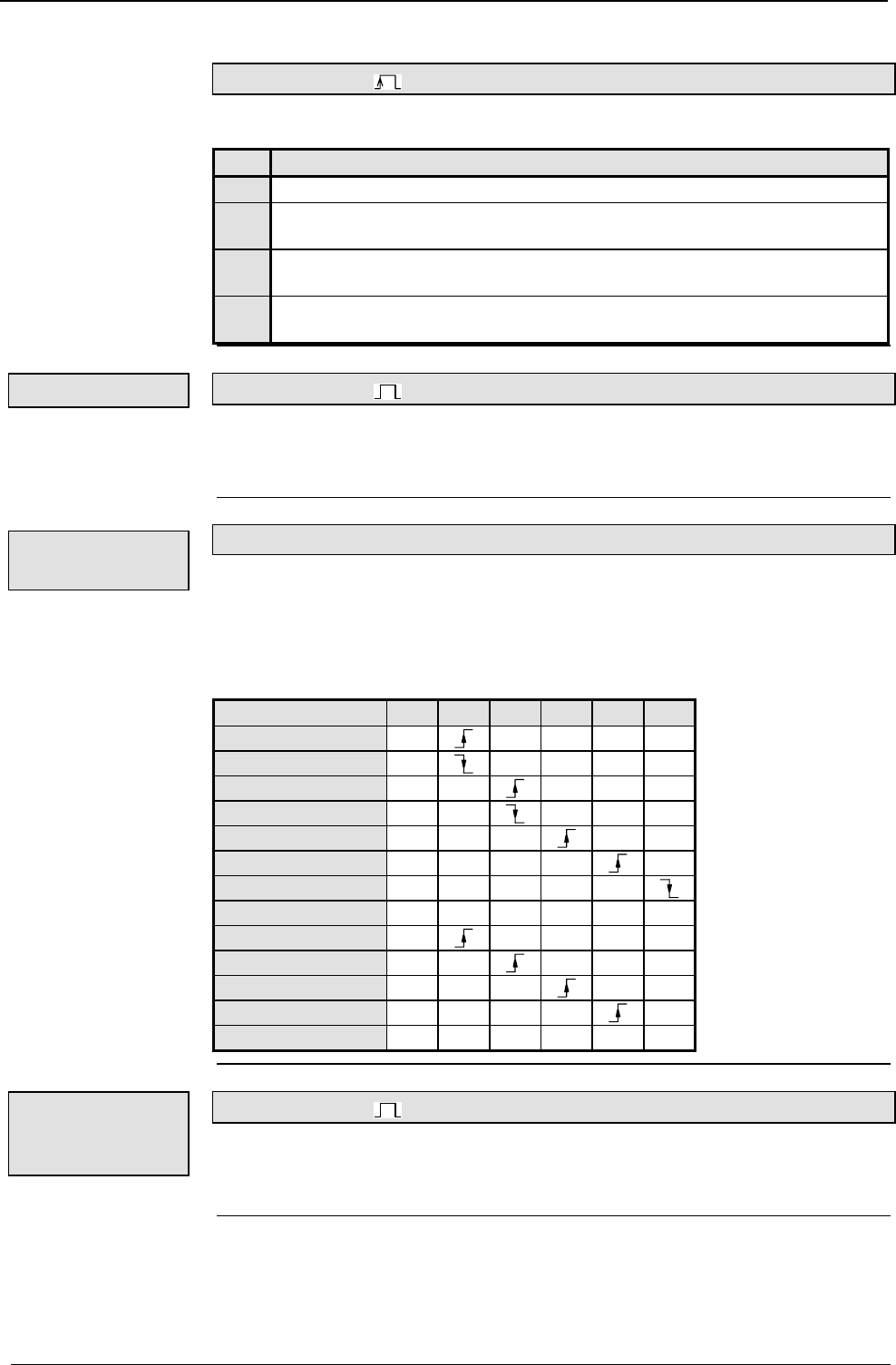
Operating Instructions COMPAX-M / -S
Digital inputs and outputs
150
Input SHIFT I5
♦
When P211="3", the data record indicator is set to 1 using "Shift I5".
P211 Function
= 0 The functions I1 + I4, Teach N, I1 + I5 and Teach Z are enabled.
= 1 Teach Z is blocked; the data record indicator is set to 1 using I1 + I4 or
"Teach Z".
= 2 Teach N is blocked; the data record indicator is set to 1 using I1 + I5 or
"Teach N". (Teach Z is enabled)
= 3 The functions Teach N and Teach Z are blocked. With I1 + I4, Teach N, I1
+ I5 or Teach Z, the data record indicator is set to 1.
Input SHIFT I6
♦
The positioning process is interrupted, the axis is stopped.
♦
O4 "Ready for start" is reset.
♦
The program data record is not ended after a start. The next data record applies.
♦
During an EMERGENCY STOP, the data record is interrupted, the drive brakes
with braking time P10; after P10, the motor is switched off.
♦
The interrupted data record is continued to its completion after acknowledgment
and START.
Transfers that trigger functions are described. All other transfers and statuses do
not trigger any functions.
Function I1 I2 I3 I4 I5 I6
Start Hand+ 00000
End Hand+ XXXX0
Start Hand- 00 000
End Hand- XX XX0
QUIT 000 00
START 0000 0
START 00001
STOP 0XXXX1
Find MZ 10000
Approach RZ 10 000
Teach - RZ 100 00
SHIFT I5 1000 0
BREAK 1XXXX1
Input I11
♦
Function is switched on by P232="4" (see Page 136).
♦
I11="0":External position adjustment switched off (reaction time approx. 5 ms).
♦
I11="1":External position adjustment switched on.
P211: blocking
and modifying
teach in functions
Break
EMERGENCY
STOP
Triggering
functions:
Activate
position
adjustment
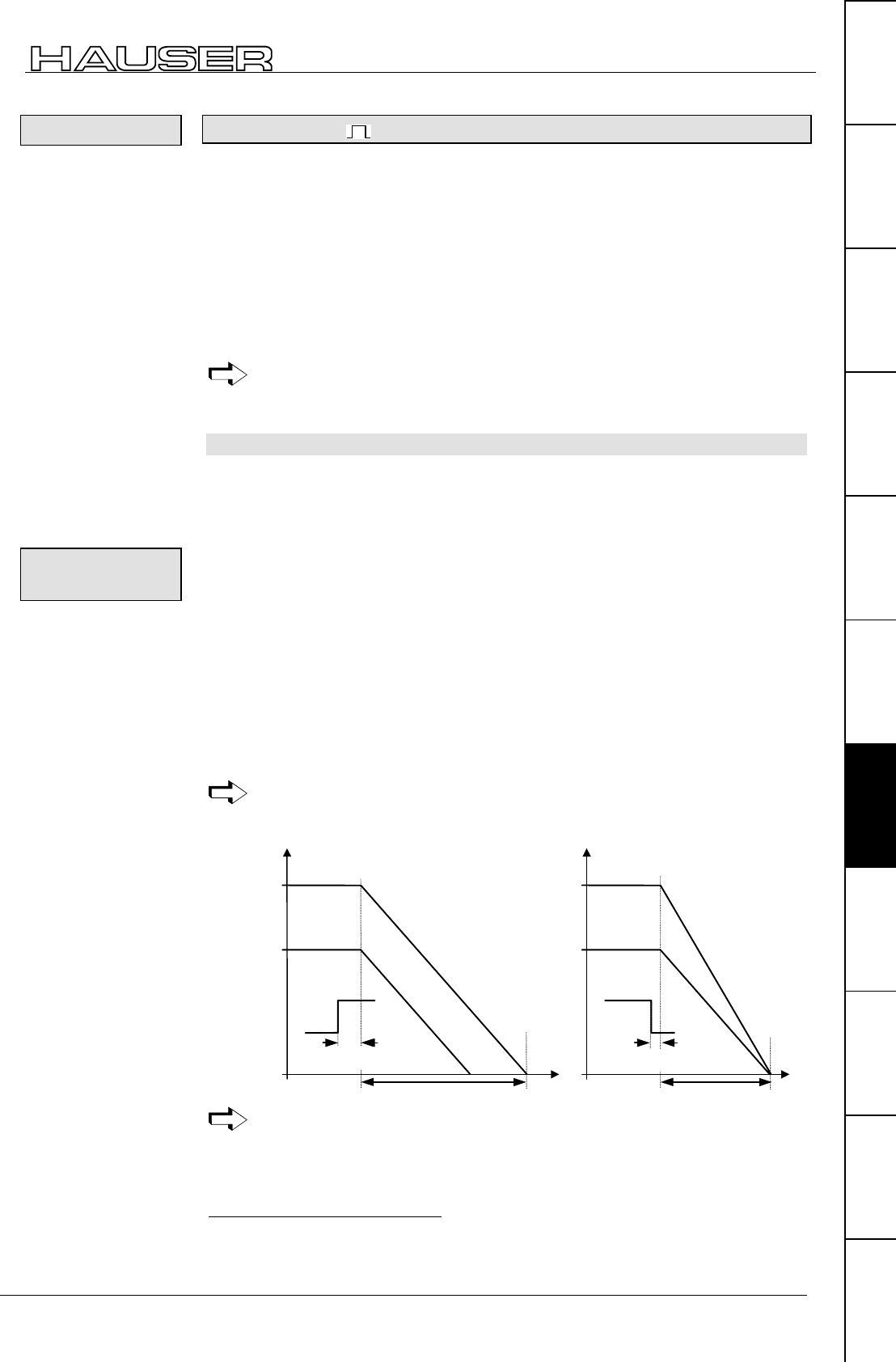
Interfaces
Digital inputs and outputs
151
Unit
hardware
Connector
assignment / cable
Technical dataConfigurationPositioning and
control functions
Optimization
functions
InterfacesAccessories /
options
StatusParameterError list
Input I15 Special START input
♦
Input for fast and defined starting of positioning process.
♦
The "Fast start" function is switched on using P18=2 or 3 (when using P18=3, the
PLC data interface is also switched on).
♦
When I15="0", all positioning processes (POSA, POSR) are blocked.
♦
When I15="1", positioning processes are started. I15 has no influence during a
positioning process.
♦
A positioning process interrupted with STOP is continued using START (I5="1")
and "Fast START" (I15="1").
♦
The reaction time of I15 before the start of the positioning process is 1.5 ms.
♦
I15 has no effect in speed control mode.
Note! The START signal (I5) is not replaced by I15; after STOP, a START
signal (I5) is required to start the program and for WAIT START.
8.6.1.6 Synchronous STOP using I13
I13 in the standard model (COMPAX XX00) provides a STOP function with which
you can stop and idle multiple COMPAX units simultaneously, regardless of the
current speed.
P219=128 or 135 enables the synchronous stop via I13 (P219 bit 736=1).
I13="1": Normal mode
I13="0": Synchronous STOP is activated.
After I13="0"
♦
the drive is stopped using P10 as the absolute ramp time and
♦
the ramp type selected via P9437.
♦
Error message E08 is output,
♦
O1 is set to 0 and
♦
the ready contact is opened.
While I13=0, any further positioning attempts are negatively acknowledged with
E08. No negative acknowledgment comes from HEDA.
Synchronous STOP function using I13 is only available on the standard unit
(COMPAX XX00).
Stop using I6 Stop using I13
2...5ms
60%
100%
tt
P10
STOP
(I6)
The same
brake ramp
Speed
COMPAX 1
Speed
COMPAX 2
<1,1ms
STOP
(I13)
Brake ramp
P10 (absolute)
Speed
COMPAX 1
Speed
COMPAX 2
P10
Using I13 for stop bring both axes to a stop simultaneously.
36 Bit counting begins with bit 0.
37 A modified ramp time is used after "VC" for the "Synchronous stop via I13"
function.
Fast start
Synchronous
STOP:
Diagram:

Operating Instructions COMPAX-M / -S
Digital inputs and outputs
152
If MZ travel is interrupted by the synchronous stop, then O3 "Machine zero
approached" is not output.
P219 = xx000000=0: COMPAX-M does not evaluate the additional emergency
stop input.
(Additional emergency stop input: X9/5-X9/6 (front plate);
COMPAX-M only)
P219 = xx000111=7: Emergency stop with P10 as relative ramp time, then switch
off, message E56, display E56, output O1 = 0, ready contact
removed.
Also effective in programming mode!
Note for MZ travel:
Additional
assignment of
P219:

Interfaces
Digital inputs and outputs
153
Unit
hardware
Connector
assignment / cable
Technical dataConfigurationPositioning and
control functions
Optimization
functions
InterfacesAccessories /
options
StatusParameterError list
8.6.1.7 Function of outputs
O1
♦
O1="1" if there is no error for group E1 ... E57.
♦
O1="0" if there is an error for group E1 ... E57; the drive does not accept
positioning commands.
O2
♦
O2="1" if there are no errors ≥E58.
♦
O2="0" if there is an error ≥E58.
O2 is assigned the "Idle display" function via P227 bit 1="1" (see Page ).119
O3
♦
When "1" is displayed, this indicates that a reference system has been defined,
i.e. there is information about the position of machine zero.
♦
When in "Normal mode", positioning is only possible when O3="1".
♦
By using an absolute value sensor and the relevant option (O1), O3="1" remains
as such even if the unit has been switched off in the meantime.
♦
Once the "Find machine zero" function has been activated (I1&I2="1"), O3="0"
until machine zero is found.
O4
♦
"Ready for START" is used for program control.
♦
O4 is set,
♦
if the program is at a WAIT START instruction and waiting for the START signal,
♦
after an interruption with STOP or BREAK and these signals are no longer
present,
♦
after a corrected error condition and
♦
after Power On.
♦
at program end with the END command.
♦
O4 has no significance for direct command specifications.
O5
♦
O5 is set to "0" when starting a positioning process; this applies for POSA,
POSR, WAIT POSA, WAIT POSR, approach real zero, approach machine zero,
Hand+, Hand-.
♦
O5 is set once the positioning has been completed in the correct manner. This
applies for POSA, POSR, WAIT POSA, WAIT POSR, approach real zero.
POSR 0 causes the brief resetting of O5.
♦
Conditions for O5="1":
♦
The actual position value is in the positioning window (+/-P14) and
♦
the nominal value sensor has reached the target point of the nominal value
specification.
♦
O5 is set in speed control mode, if the nominal value generator has processed
the speed ramp.
No fault
No warning
Machine zero
has been
approached
Ready for start
Position
reached
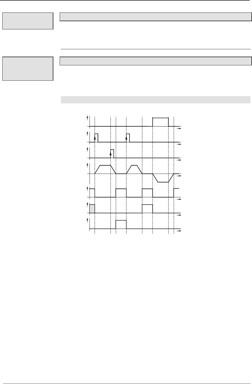
Operating Instructions COMPAX-M / -S
Digital inputs and outputs
154
O6
♦
O6="1" indicates that the axis is at a standstill due to a STOP (I6) or BREAK
(I1&I6).
♦
O6 is reset when the axis moves again.
O16
♦
Only assigned if mark reference is activated (P35=1).
♦
With "0", the mark disappears once the maximum feed length is reached (see
Page 100)
8.6.1.8 Diagrams:
t
t
t
t
tt
tt
t
I3
Jog-
I5
Start
I6
Stop
V
O4
Ready
to Start
O5
Progr. target
pos. reached
O6
Out of action
after stop
0
01 23 4 5 6 78
0 COMPAX ready for new start.
1 When using START at input I5, the outputs O4 and O5 are reset. The axis moves.
2 Interruption using STOP at input I6. After idle, message at output O6 (3).
4 START using I5. Positioning process is continued.
5 Positioning process ended. Message via O4 and O5="1".
6 Manual processing of axis. O5 and O4 ="0".
7 Specification for manual processing ended. Drive decelerates.
8 Manual process ended. Drive at standstill. Ready message for output O4 is set.
Idle after stop
or break
Mark missing
after maximum
feed length
In data record
memory mode
Caption:
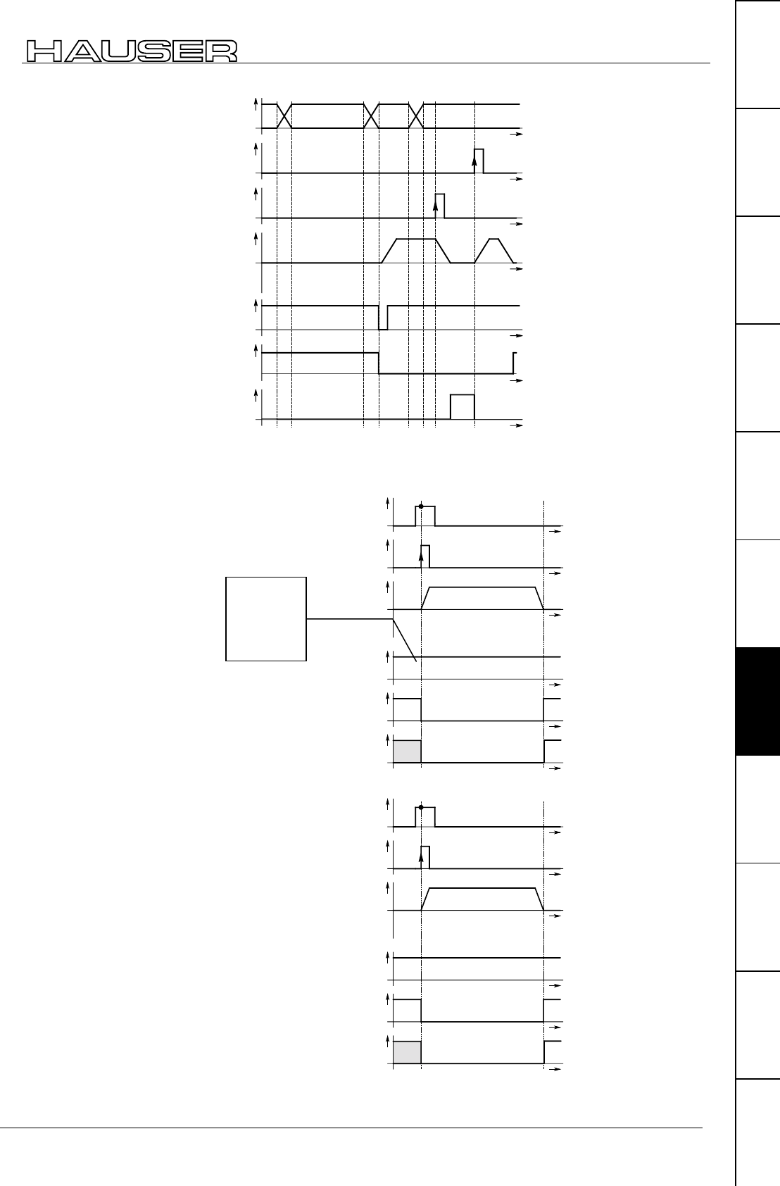
Interfaces
Digital inputs and outputs
155
Unit
hardware
Connector
assignment / cable
Technical dataConfigurationPositioning and
control functions
Optimization
functions
InterfacesAccessories /
options
StatusParameterError list
t
t
t
t
tt
tt
t
Inter-
face
I5
Start *
I6
Stop
V
O4
Ready
to start
O5
Progr. target
pos. reached
O6
Out of action
after stop
0
012345678
POSA 100 CR
* When using this START, a processing command interrupted by STOP and
specified by a interface is restarted.
t
t
tt
tt
t
I1
SHIFT
I3
Drive to RN
V
0
t
O4
Ready
to start
O5
Progr. target
pos. reached
O3
Machine zero
reached
t
t
tt
tt
t
I1
SHIFT
I3
Drive to RN
V
0
t
O4
Ready
to start
O5
Progr. target
pos. reached
O3
Machine zero
reached
Direct command
specification
Finding machine
zero in normal
mode
Approaching real
zero
Before the
1st machine
zero travel,
O3="0"
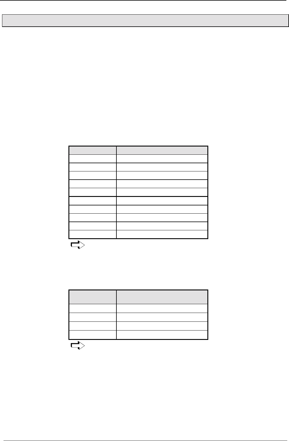
Operating Instructions COMPAX-M / -S
PLC data interface (function not available with COMPAX 1000SL)
156
8.6.2 PLC data interface (function not available with COMPAX 1000SL)
This universal data interface allows data to be exchanged with all PLC types,
regardless of manufacturer and origin. You will need five binary inputs and outputs
for this process. These can be divided into four data lines (BCD format) and one
control line.
♦
Direct commands
♦
Absolute and relative positioning commands (POSA, POSR)
♦
Specification of acceleration time and velocity (ACCEL, SPEED)
♦
Password enabling or modifying data record indicator (GOTO)
♦
Queries of status S1...S12 (actual values).
♦
Modifying parameters P1...P49 with defined parameter acceptance (VP).
The PLC data interface is activated by setting P18 (P18="1" or "3". When it is "3",
the "Fast start" function I15 is also switched on) and by switching off and on. The
following binary inputs and outputs are assigned:
Input/output Meaning
I7 (X8/7) Control line "UBN"
I8 (X8/8) Data bit 20
I9 (X10/1) Data bit 21
I10 (X10/2) Data bit 22
I11 (X10/3) Data bit 23
O7 (X8/15) Control line "RDY"
O8 (X8/16) Data bit 20
O9 (X10/9) Data bit 21
O10 (X10/10) Data bit 22
O11 (X10/11) Data bit 23
O7...O11 are no longer available for the OUTPUT command. The GOSUB
EXT and GOTO EXT commands are no longer permitted when P18="1".
Instead use the GOTO command.
Each transfer begins with the start letter "E" and ends with the end letter "F". In
between them is the command. This consists of two BCD numbers (called function
code) for the command type and of numerical values for position, velocity,
acceleration time, etc. The numerical values can contain special figures:
Figure
BCD coded Meaning
"D" ≡ "1101" Negative prefix
"0" ≡ "0000" Positive prefix
"C" ≡ "1100" Decimal point
"A" ≡ "1010" Assignment "="
Use status S29 to e.g. track the interface data via the front plate display.
Functions
available:
Activation:
Interfaces
PLC data interface (function not available with COMPAX 1000SL)
157
Unit
hardware
Connector
assignment / cable
Technical dataConfigurationPositioning and
control functions
Optimization
functions
InterfacesAccessories /
options
StatusParameterError list
Syntax of individual commands:
Start sign "E" ≡ "1110"
Function code 1: "0" ≡ "0000"
Function code 2: "1" ≡ "0001": POSA
"2" ≡ "0010": POSR
Sign "0" ≡ "0000": positive
"D" ≡"1101": negative
Numerical value 106
Numerical value 105
Numerical value 104
Numerical value 103
Numerical value 102
Numerical value 101
Numerical value 100
Decimal point "C" ≡ "1100"
Numerical value 10-1
Numerical value 10-2
Numerical value 10-3
End sign "F" ≡ "1111"
Start sign "E" ≡ "1110"
Function code 1: "0" ≡ "0000"
Function code 2: "4" ≡ "0100"
Sign "0" ≡ "0000": positive
"D" ≡"1101": negative
Numerical value 101
Numerical value 100
Decimal point "C" ≡ "1100"
Numerical value 10-1
Numerical value 10-2
Numerical value 10-3
End sign "F" ≡ "1111"
Start sign "E" ≡ "1110"
Function code 1: "0" ≡ "0000"
Function code 2: "5" ≡ "0101"
Sign "0" ≡ "0000": positive
"D" ≡ "1101":negative
Numerical value 104
Numerical value 103
Numerical value 102
Numerical value 101
Numerical value 100
End sign "F" ≡ "1111"
Start sign "E" ≡ "1110"
Function code 1: "0" ≡ "0000"
Function code 2: "6" ≡ "0110"
Numerical value 102
Numerical value 101
Numerical value 100
End sign "F" ≡ "1111"
Positioning
commands POSA,
POSR
Velocity
specification
SPEED
Acceleration time
ACCEL
Adjust data
record indicator /
enable password:
GOTO

Operating Instructions COMPAX-M / -S
PLC data interface (function not available with COMPAX 1000SL)
158
Start sign "E" ≡ "1110"
Function code 1: "1" ≡ "0001"
Function code 2: "3" ≡ "0011"
Parameter No. tens column
Parameter No. digits column
Assignment code: "A" ≡ "1010"
Sign "0" ≡ "0000": positive
"D" ≡"1101": negative
Numerical value 106
Numerical value 105
Numerical value 104
Numerical value 103
Numerical value 102
Numerical value 101
Numerical value 100
Decimal point "C" ≡ "1100"
Numerical value 10-1
Numerical value 10-2
End sign "F" ≡ "1111"
Start sign "E" ≡ "1110"
Function code 1: "1" ≡ "0001"
Function code 2: "4" ≡ "0100"
End sign "F" ≡ "1111"
Start sign "E" ≡ "1110"
Function code 1: "1" ≡ "0001"
Function code 2: "6" ≡ "0110"
Numerical value 101
Numerical value 100
End sign "F" ≡ "1111"
Start sign "E" ≡ "1110"
Sign "0" ≡ "0000": positive
"D" ≡"1101": negative
Numerical value 106
Numerical value 105
Numerical value 104
Numerical value 103
Numerical value 102
Numerical value 101
Numerical value 100
Decimal point "C" ≡ "1100"
Numerical value 10-1
Numerical value 10-2
Numerical value 10-3
End sign "F" ≡ "1111"
The following signs are not necessary when transferring:
♦
Positive prefixes and initial zeros.
♦
For whole number values: the decimal point and the figures after the decimal
point.
Modify
parameters
P1...P49
Acceptance of VP
parameter
Status query
S1...S12 (actual
values)
Status response
S1...S12 (actual
values)
Interfaces
PLC data interface (function not available with COMPAX 1000SL)
159
Unit
hardware
Connector
assignment / cable
Technical dataConfigurationPositioning and
control functions
Optimization
functions
InterfacesAccessories /
options
StatusParameterError list
Function code
BCD coded Command
F-code1 F-code2
0 1 POSA
02POSR
0 4 SPEED
05ACCEL
0 6 GOTO
1 3 Modify parameters (P1-P49)
1 4 VP (valid parameter)
1 6 Query status (S1-S12)
♦
PLC assigns the sign (4 bit) to I8...I11.
♦
Once the data is stable, the PLC sets the UBN to "1".
♦
COMPAX reads the sign and sets RDY to "0".
♦
PLC sets UBN to "0".
♦
COMPAX sets RDY to high.
If the data direction is then reversed, COMPAX can set the RDY line to "0". This is
the case for the last sign of a status query.
♦
PLC sets UBN to "1".
♦
COMPAX assigns the sign (4 bit) to O8...O11.
♦
COMPAX sets RDY to "1"
♦
PLC reads the sign and sets UBN to "0".
♦
COMPAX sets RDY to "0".
If the data direction is then reversed, COMPAX can set the RDY line to "1". This is
the case for the last sign of a status response.
Signal procedure using the example of a status query
PLC
Data
4 Bit
COMPAX
Data
4 Bit
PLC
UBN
COMPAX
RDY
t
valid valid valid
valid valid valid
valid valid
PLC COMPAX COMPAX PLC PLC COMPAX
It is important that the data ready message is only assigned after the data
(when using PLC, one cycle later); i.e. once the data has been safely
assigned.
If a fault means that the signal "RDY" is missing, the interface can be reset to its
initial status using signal "E" (start sign). The next "UBN" is then detected even
though "RDY" is missing.
Function codes of
commands
Procedure for
transmitting a
sign
Exception:
Process for
receiving a sign
Exception:
Reset interface
Operating Instructions COMPAX-M / -S
RS232 interface
160
8.6.3 RS232 interface
You can communicate with COMPAX via an RS232 interface on a PC. The
following functions are available.
♦
Direct command input and execution in on-line mode.
♦
Read status values.
♦
Read and write program data records (the complete stock of commands is
available here).
♦
Read and write (password protected) parameters.
♦
Transmit control instructions.
8.6.3.1 Interface description
Interface RS 232
Baud rate: 9600* or 4800 (selected with P19)
COMPAX 1000SL: fixed setting 9600
Word length: 8 bit
Stop bit: 1
Parity: none
Hardware handshake: yes (RTS,CTS)
Software handshake: XON, XOFF (can be selected using P20)
Entry buffer: error string, max. 30 characters
Output buffer: status string, max. 30 characters
Data format: ASCII
End sign: CR (carriage return) or CR LF (carriage return, line
feed)
* Default setting; simultaneously press the three front plate buttons while switching
on to set COMPAX to 9600 Baud.
♦
all displayable ASCII characters
♦
any inserted spaces
♦
a function sign, if nec. ($, ?, !)
♦
CR (carriage return) for storing the command in the intermediate memory. If no
function signs have been transmitted, the command is accepted and executed if
necessary (see next page).
♦
LF (line feed) has no meaning to COMPAX
COMPAX only receives a command if a previously transmitted command
was answered with CR LF >.
♦
if the syntax is error-free with CR LF > or the required response and CR LF >
♦
if there are errors, depending on the contents of P20
$Automatic "Position reached" message
1. only applies to POSA and POSR
2. COMPAX transmits: $CRLF> when the position is reached.
,Interpreting and storing commands
COMPAX stores the instruction in the intermediate memory (capacity: one
instruction) without executing it.
?Echo
COMPAX sends the data received with CRLF>.
!Executing commands
Whenever a "!" occurs, the instruction is executed from the intermediate
memory.
These function signs can be attached to any instruction.
Example: POSA 100 $ CR LF
COMPAX moves and responds once position 100 is reached with: $ CR LF >
Interface
parameters
COMPAX receives
COMPAX
responds:
Meaning of
function signs
Interfaces
RS232 interface
161
Unit
hardware
Connector
assignment / cable
Technical dataConfigurationPositioning and
control functions
Optimization
functions
InterfacesAccessories /
options
StatusParameterError list
Function Activation using P20 Valid
from
Software
handshake
"0": without
"1": with XON, XOFF
Power
on
Error transmission "0": Error only when there is activity at the interface
and if the transmitted command triggers an error.
No negative command acknowledgement (E90
...E94).
"2": No transmission of error or negative command
acknowledgments (E90 ...E94).
"4": Messages are indicated for all errors and negative
command acknowledgments (E90 ...E94) when
they occur using Exx CR LF >.
"6": Error and negative command acknowledgement
(E90 ...E94) only when there is activity at the
interface.
Imme-
diately
End sign selection "0": CR LF > "8": CRPower
on
Binary transfer "0": without "16": with imme-
diately
BCC: Block check "0": without "128": with
(EXOR via all signs apart from the end sign)
Power
on
Implment the required setting by entering the sum of the set values in P20.
Example in Quick-Basic of how to transmit and receive COMPAX data via the RS232
interface.
DIM text$(30) ´ The text string "text$" is defined with a length of 30.
a$="com1:9600,N,8,1" ´
´
´
´
´
´
The interface parameters are assigned to the "a$" string. Meaning:
com1:the com1 serial interface is used.
9600: sets baud rate to 9600
N: no parity
8: 8 bit word length
1: one stop bit
OPEN a$ for RANDOM AS #1 ´ The interface is initialized and marked with #1 (channel 0).
text$="S1" ´ Status S1 must be queried.
PRINT #1,text$ ´ text$ is output on channel 1.
text$="" ´ text$ is deleted so that the response can be accepted.
INPUT #1, text$ ´ S1 is read by channel 1 in text$
PRINT text$ ´ S1 is output on screen
END
P20: Software
handshake (SH) /
error
transmission
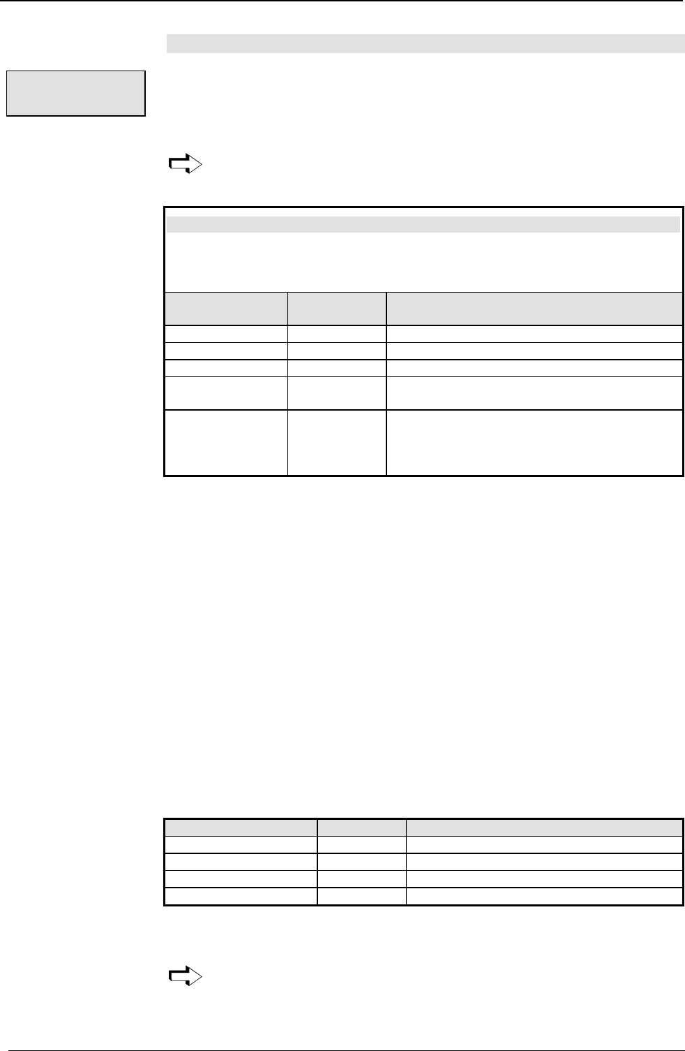
Operating Instructions COMPAX-M / -S
RS232 interface
162
8.6.3.2 Interface functions
When making direct command entries via RS232, use the abbreviated form for
most instructions (two letters).
Refer to table on Page 165!
When using "Direct command entry", write an "END" instruction in data
memory No. 1 because the start command refers to the program memory if
the unit contains no direct commands.
Preparatory positioning commands
3. These commands can be transmitted to COMPAX when idle and during a
positioning process.
4. The commands are accepted with the next positioning command
Instruction Abbreviated
form Meaning
ACCEL AL Accelerating and braking time in ms
ACCEL- AL- Separate specification of braking time.
SPEED SD Velocity in %
POSR value1
SPEED value2 PR SD Preparation for speed step profiling.
POSR value1
OUTPUT Oxx=y PR OT Sets comparator function.
The comparators are also indicated using
"CRLF> comparator No." via RS232 (see
example 2).
Example 1: POSR 100 SPEED 50 CR LF or
PR 100 SD 50 CR LF
Prepares a speed step.
Example 2: PR 200 OT O9=1 1st comparator
PR 100 OT O10=1 2nd comparator
POSA1000$
The following signs are returned:
♦
2 CRLF > after 100 units
♦
1 CRLF > after 200 units
♦
$ CRLF > after 1000 units
♦
Positioning commands can be transmitted to COMPAX when idle and during a
positioning process.
♦
If the axis is moving, the command is acknowledged negatively.
♦
The current settings (ACCEL, SPEED, ...) apply to the positioning command; i.e.
these settings can still be modified before the positioning command is
transmitted.
♦
A positioning command specified by the interfaces is interrupted by a reference
journey prompted by the digital inputs. (POSA, POSR, LOOP).
Instruction Abbr. form Meaning
POSA PA Absolute position
POSA HOME PH Find machine zero
POSR PR Relative position
OUTPUT O0 OT O0 Switch off drive
Example 1: POSA 2500CRLFor PA 2500CRLF
Proceed to position 2500
This command is only permitted if COMPAX has not received any more
commands since the positioning command currently being processed
(excluding commands which are not position dependent, such as OUTPUT,
GOTO and ACCEL, ACCEL-).
Direct
command entry
Commands
permitted for the
various modes of
operation
Positioning
commands
Influencing the
active positioning
process
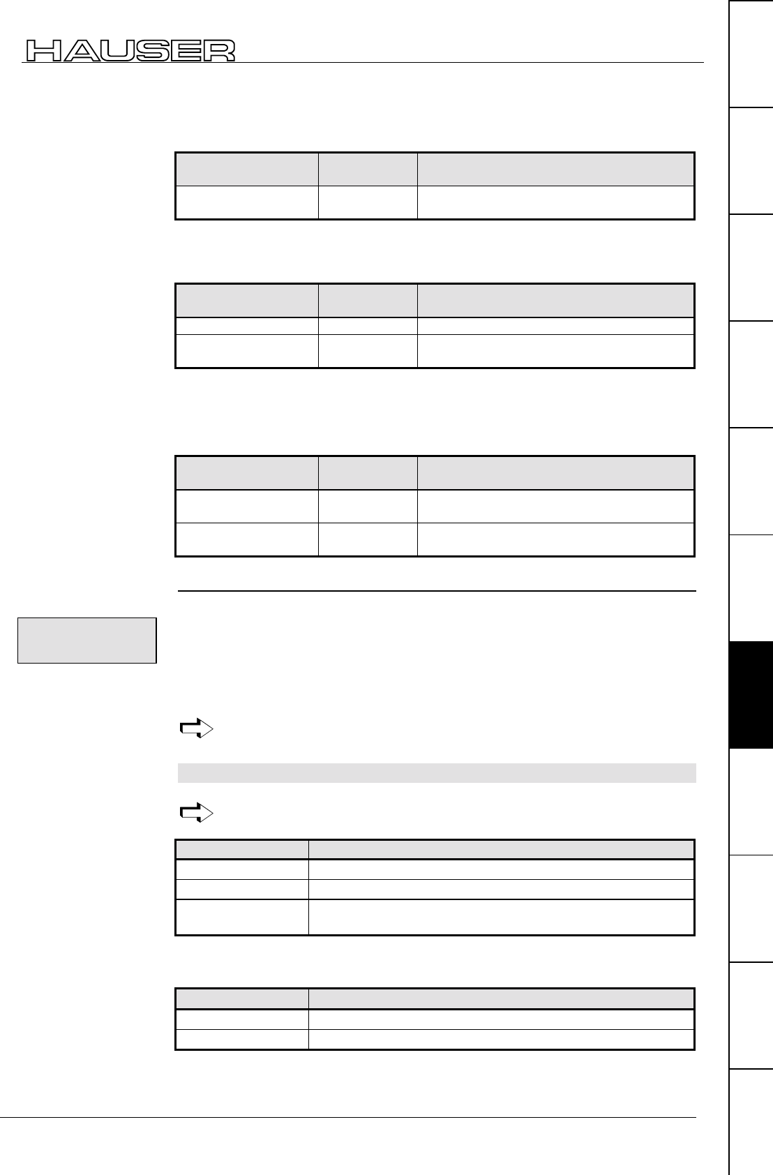
Interfaces
RS232 interface
163
Unit
hardware
Connector
assignment / cable
Technical dataConfigurationPositioning and
control functions
Optimization
functions
InterfacesAccessories /
options
StatusParameterError list
♦
Direct modification of velocity of an active positioning process.
♦
The type of speed transfer and the ensuing braking ramp can be influenced by
previously modified acceleration times (ACCEL, ACCEL-).
Instruction Abbreviated
form Meaning
POSR 0 SPEED
value PR 0 SD Direct speed modification.
♦
These commands are processed regardless of a positioning process specified by
the interface (not during an internal data record procedure).
Instruction Abbreviated
form Meaning
OUTPUT OT Set output
GOTO GO Adjusts data record indicator
and enables / blocks password.
♦
The axis must be at a standstill if modified VP parameters are to be transferred.
♦
The axis must be switched off if modified VC parameters are to be transferred
(e.g. via OUTPUT O0=1).
Instruction Abbreviated
form Meaning
VALID
PARAMETER VP Modified parameter accepted (not
configuration parameters).
VALID
CONFIGURATION VC All parameters are accepted with VC.
Use the serial interface to query all status values, even during a positioning
process.
♦
Sxx transmitted, xx = number of the status value.
♦
COMPAX returns the current value.
Example: S1 CR LF
Response: S001:xxxxxxxx,xxxmm CR LF >
The decimal point for S1 - S12 is always the ninth digit after the ":".
8.6.3.3 Read and write program sets and parameters
Also possible during a positioning process.
Instruction Meaning
Nxxx: Instruction Write set xxx with instruction.
Pxxx=value Write parameter xxx with value.
Pxxx="name"
(Only for P40-P49)
Assigns parameter xxx with name.
Example: N005: POSA 100 CR LF or N005: PA 100 CR LF
The POSA 100 instruction is written in data record 5.
Instruction Meaning
Nxxx Read data record xxx.
Pxxx Read parameter xxx.
Commands which
are not position-
dependent
Commands which
are only permitted
when drive is idle
Read the status
values
Download: writing
the sets and
parameters
Upload: read the
sets and
parameter
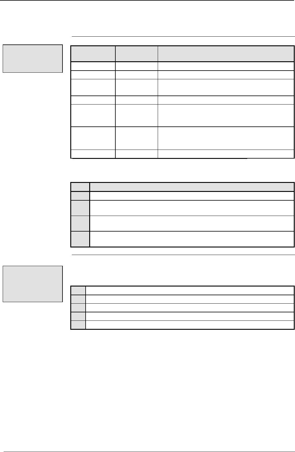
Operating Instructions COMPAX-M / -S
RS232 interface
164
Example: P40 CR LF
COMPAX transmits the contents of P40: P40=value name CR LF>
Instruction Abbreviated
form Meaning
START Nxxx SNxxx Execute program set xxx (this set only).
START ST Start program.
STOP SP Stop program/positioning.
SP corresponds to a STOP pulse
QUIT QT Acknowledge error
TEACH Z TZ Accepts current position as real zero point. (P1 is
modified).
The data record indicator is set to 1.
TEACH Nxxx TNxxx Current position is written into set xxx using the
POSA command.
Not possible in "Reset mode".
BREAK BK Interrupts positioning or program step.
Example: START N010 CR LF or SN 010 CR LF
Set 10 is executed
P211 Function
= 0 The functions I1 + I4, Teach N, I1 + I5 and Teach Z are enabled.
= 1 Teach Z is blocked; the data record indicator is set to 1 using I1 + I4 or
"Teach Z".
= 2 Teach N is blocked; the data record indicator is set to 1 using I1 + I5 or
"Teach N". (Teach Z is enabled)
= 3 The functions Teach N and Teach Z are blocked. With I1 + I4, Teach N, I1
+ I5 or Teach Z, the data record indicator is set to 1.
If commands are issued using RS232 and they cannot be executed (invalid
commands, missing password or COMPAX is busy), a warning is sent back.
Meaning:
E90 Syntax error; command not valid
E91 Command cannot be executed in this COMPAX operating mode.
E92 Function running, command cannot be executed
E93 Data record memory active, command cannot be executed
E94 Password missing
These warnings are not entered in status S18 (error history).
Transmitting
control
instructions
P211: blocking
and modifying the
teach in functions
Negative
command
acknowledge-
ment
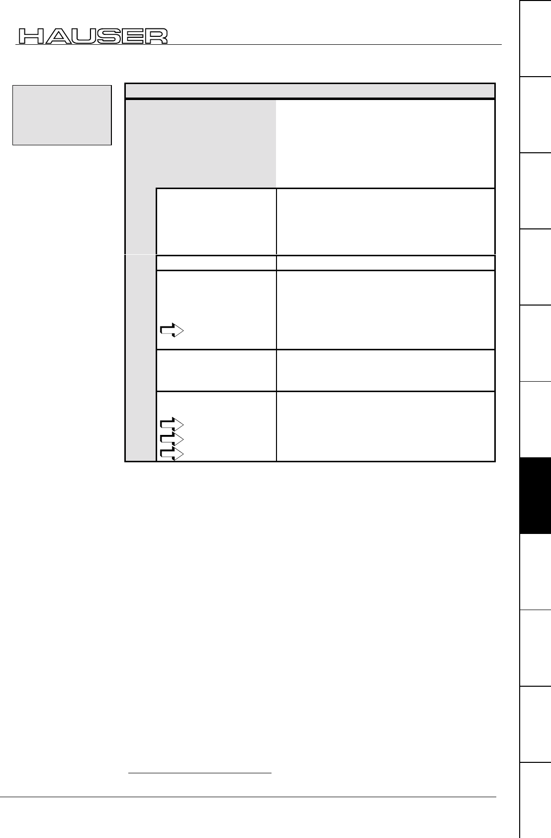
Interfaces
RS232 interface
165
Unit
hardware
Connector
assignment / cable
Technical dataConfigurationPositioning and
control functions
Optimization
functions
InterfacesAccessories /
options
StatusParameterError list
Operating status Commands available
Commands available in
all operating modes /
statuses
♦
Status query (Sxx)
♦
Parameter query and assignment (Pxxx,
Pxxx=value)
♦
Data record query and assignment (Nxxx,
Nxxx=value)
♦
Set / reset outputs (OUTPUT Ox=y); Not
OUTPUT O0!
♦
Stop
♦
Emergency stop
♦
OFF (motor switched
off)
♦
Error present
♦
VP, VC, VF
♦
Quit
♦
OUTPUT O0
♦
GOTO data record indicator / password
♦ ♦
In data record operation ♦
VP
♦
During positioning
process
(as preparation for the
next command)
No program
processing!
♦
VP
♦
SPEED38 / ACCEL
♦
POSR value SPEED value / POSR value
OUTPUT Ox=y
♦
GOTO data record indicator / password
♦
Find machine zero
♦
Approach real zero
♦
Manual +/-
No other commands possible!
♦
During RUN and
motor under torque
No positioning!
No stop present!
No error present!
All commands and functions are possible!
38 SPEED is not available in speed control mode.
Authorization of
commands in
different modes
of operation
Operating Instructions COMPAX-M / -S
RS232 interface
166
8.6.3.4 Binary data transfer using RS232
A series of commands can be transferred in the COMPAX internal binary format for
time-critical applications. This saves times as ASCII into COMPAX internal binary
format conversion is not required. You can still transfer data in the normal ASCII
format (mixed mode).
P20 = P20 + 16
Adds 16 to the required P20 setting (see interface parameters section in the User
Guide). This ensures that binary data transfer is available in addition to normal
transfer (ASCII).
P20="3": with XON, XOFF; no error response message; no binary data transfer.
P20="19": with XON, XOFF; no error response message; binary data transfer.
!The end sign must not be transmitted!
!The entire length of the binary format must always be transferred!
!Function signs ("$" "," "?" "!") are not available when using binary transfer.
as ASCII transfer:
♦
without error: using "CR LF >".
♦
with error: depending on the value of P20
(refer to "Error transmission" in the User Guide).
Command Binary format (hexadecimal)
POSA value 88 41 xx xx xx xx xx xx
LSB MSB
POSR value 88 52 xx xx xx xx xx xx
LSB MSB
SPEED value 88 53 xx xx xx xx xx xx
LSB MSB
ACCEL value 84 4C yy yy
MSB LSB
ACCEL- value 84 44 yy yy
MSB LSB
OUTPUT Oyy=0 85 4F yy yy 30
MSB LSB
OUTPUT Oyy=1 85 4F yy yy 31
MSB LSB
POSR value OUTPUT Oyy=0 8C 52 xx xx xx xx xx xx 4F yy yy 30
LSB MSB MSB LSB
POSR value OUTPUT Oyy=1 8C 52 xx xx xx xx xx xx 4F yy yy 31
LSB MSB MSB LSB
POSR value1 SPEED value2 8F 52 xx xx xx xx xx xx 53 xx xx xx xx xx xx
LSB MSB LSB MSB
Numerical formats of "xx xx xx xx xx xx" *2
3 bytes after the decimal point, 3 bytes before the decimal point.
Valency:
2-24 2-23 ... 2-2 2-1 , 20 21 22 ... 222 223
Transmission sequence, e. g.: "88 41 LSB....MSB"
2 bytes before the decimal point.
no digits after the decimal point.
P20: switching on
binary data
transfer
Example:
COMPAX response
Meanings of the
binary command
codes
Numerical formats
Numerical formats
of "yy yy"
Interfaces
RS232 interface
167
Unit
hardware
Connector
assignment / cable
Technical dataConfigurationPositioning and
control functions
Optimization
functions
InterfacesAccessories /
options
StatusParameterError list
Valency: *1
215 214 ... 22 21 20.
Transmission sequence, e.g.: "84 4C MSB LSB".
Negative numbers are represented in complement to two format. Creating the
complement to two:
♦
Determine bit combination of the positive numerical value.
♦
Negate the binary value.
♦
Add 1.
You can generate this format from any number (as long as it has digits after the
decimal place) as follows.
Number = 450.5
1. Multiply number by 224.
450.5 * 224 = 7 558 135 808.
2. 7 558 135 808: convert into a hexadecimal number (if necessary into an integer
first) =>0x00 01 C2 80 00 00 ≡ before decimal place, after decimal place ≡
MSB,.... LSB, MSB,.... LSB.
3. These bytes must now be entered into the commands in the sequence
specified. The sequence of the bytes is reversed. Do not alter the sequence of
the bits.
This conversion also applies to negative numbers.
Examples of the number format of "xx xx xx xx xx xx"
Number MSB LSB
10 00 00 0A 00 00 00
360 00 01 68 00 00 00
450,5 00 01 C2 80 00 00
-1 FF FF FF 00 00 00
Digits before the decimal place Digits after the decimal place
The following string will be produced, e.g. for POSA 360.0:
"88 41 00 00 00 68 01 00"
Note: transfer all digits!
Note: when binary transfer is switched on, note the following.
Only create RS232 connection when participants are switched on or
when participants are enabled, the RS232 can be re-initialized by COMPAX using
Power on.
*
1
Negative numbers
*
2
Format
conversion
Example:
Start-up during
binary transfer
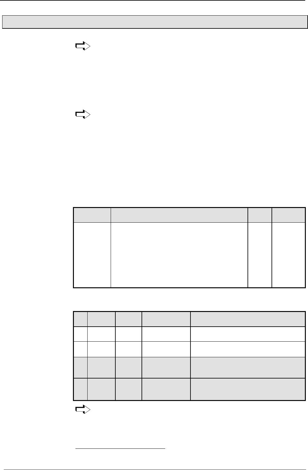
Operating Instructions COMPAX-M / -S
Process coupling using HEDA (Option A1 / A4)
168
8.6.4 Process coupling using HEDA (Option A1 / A4)
See also Page 185.
HEDA (SSI interface) can be used for synchronization of several axes with
simultaneous (±2.5 µs) processing of individual controller time slices.
The master (operating mode 1) transmits 2 synchronization words to the slave
axes, enabling them to synchronize. The slave axes (operating mode 2)
synchronize automatically. No response is transmitted from the slave axes to the
master.
The master only transmits to axis address 1. Therefore, all slaves must also be set
to address 1 (P250=1).
Acyclic communication between master and slave is not possible.
COMPAX XX00 as slave to transmit "Fast start" or as master
COMPAX XX60 as master or slave not when P212=3 and P212=4
COMPAX XX70 as master or slave only when P31=9 or 0
Max. 16 participants in the master/passive slave operating mode and max. 50m
cable length.
The units must be fitted with the O1 / A4 (COMPAX 1000SL) option. There must be
a terminating connector bus 2/01 on the last slave.
Parameter
No. Meaning Valid
from Default
value
P243 HEDA operating mode VP 0
P245* Assgn outputs O1 ... O8 to the HEDA bus imme-
diately
0
P246* Assgn outputs O9 ... O16 to the HEDA bus imme-
diately
0
P247 Max. average transmission errors VP 5
P248 Max. transmission errors VP 15
P249 Synchronization monitoring VP 10
P250 Unit addresses (in master – slave mode =1) VP 0
*In the HEDA master - HEDA slave operating mode (passive slave to COMPAX
master), P245=P246=0 is set.
No
.P243 P250 Operating
mode Description
0Not
relevant
= 0 Independent
single axis
No coupling, no synchronization
0 0 = 1 ... 9 Slave on IPM39
via HEDA
Coupled operation and acyclic
communication possible via HEDA
1Bit
0="1"
(P243=1)
= 1 COMPAX as
master Master axis transmits synchronous
word and 7 words to address 1
2Bit
1="1"
(P243=2)
= 1 Passive slave
to COMPAX
master
Slave receives at address 1 (P250=1),
but does not send anything back
Note!
If HEDA coupling is activated and the master executes "Find machine zero",
this will result in a positional offset between master and slave.
You should therefore execute machine zero travel when the HEDA coupling
is deactivated.
39 The interpolation module IPM can also be used as a master, but only with
COMPAX XX00; COMPAX XX60, COMPAX XX70
Synchronization
and fast start via
HEDA:
Variant support:
Physical limits:
Hardware
requirements:
HEDA
parameters:
Operating modes:
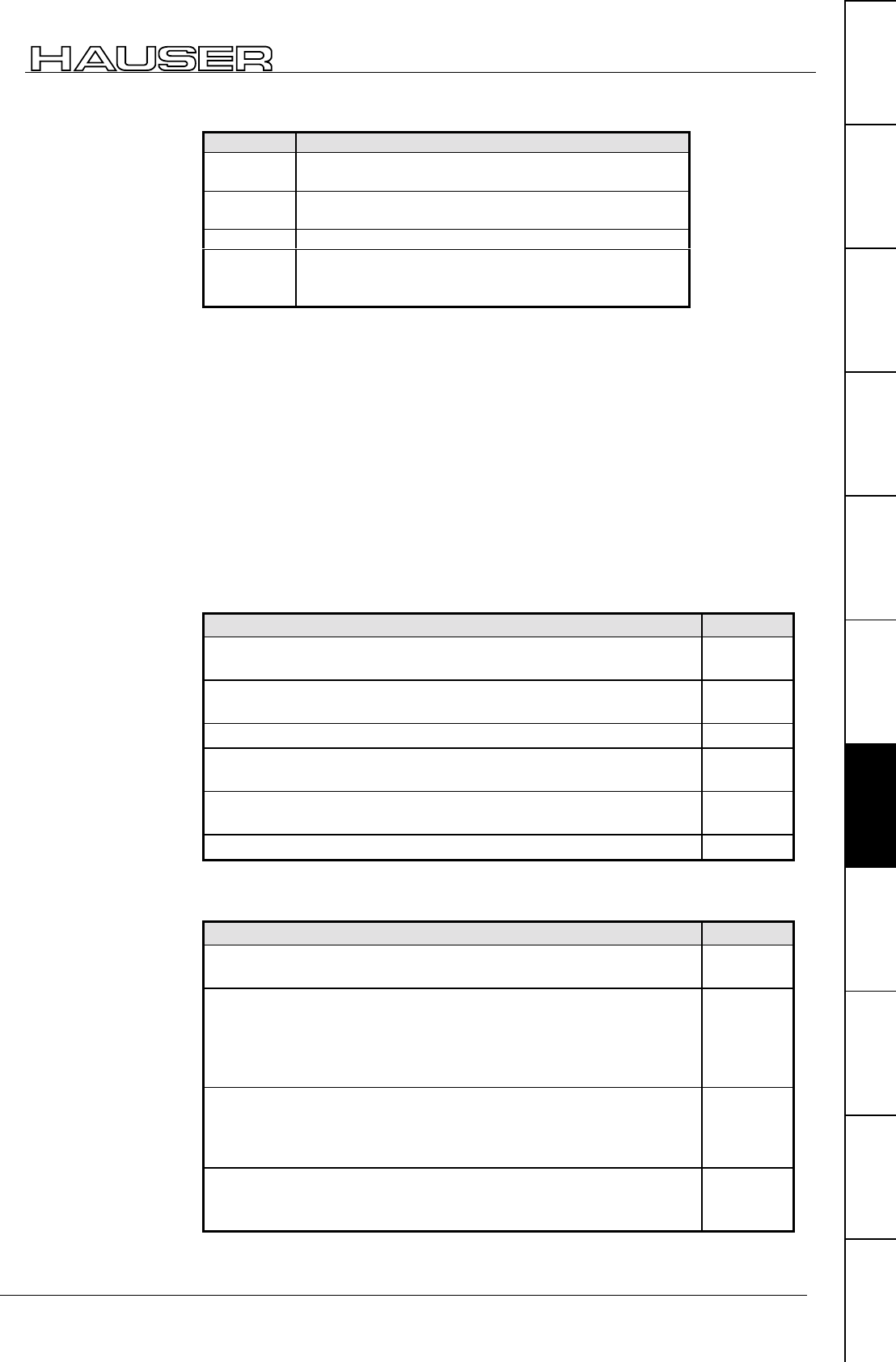
Interfaces
Process coupling using HEDA (Option A1 / A4)
169
Unit
hardware
Connector
assignment / cable
Technical dataConfigurationPositioning and
control functions
Optimization
functions
InterfacesAccessories /
options
StatusParameterError list
P18 is expanded with the following bits:
P18 Meaning
Bit 0 =0 without PLC data interface
=1 with PLC data interface
Bit 1 =0 fast start on I15 not active
=1 fast start on I15 active
Bit 2 reserved
Bit 3 =0 fast start on HEDA bit 8 not active
=1 fast start on HEDA bit 8 active
only permitted with P18: bit 1=1 (see below).
The fast start is synchronized using P18 bit 3 for HEDA with master and slave, i.e.
input 15 must be on the slave and the master fast start (triggered by I15 in master)
must also be on HEDA so that it can be executed.
This operating mode is also set with P18=10.
If I15 is not required on the slave, then set I15="1".
The fast start is additionally delayed by 1 ms for all axes; i. e. in total 2.5ms
(+1.5ms reaction time I15)
The master transmits one data block per ms to address 1, consisting of
♦
HEDA control word, inc. fast start on bit 8 (bit 8 is automatically generated in the
master from I15 "Fast start").
♦
Process value, selected with parameter P184 depending on family (COMPAX
XX00, COMPAX XX60, COMPAX XX70) between:
Output quantity Master
Encoder position (COMPAX XX70) +
master channel duration period P184=40
Internal time base / encoder velocity before P35*
(COMPAX XX70) P184=42
Scaled master position before P35* (COMPAX XX70) P184=43
Nominal position value in resolver increments
[65536 increments/revolution] P184=44
Actual position value in resolver increments
[65536 increments/revolution] P184=45
Differentiated resolver position [increments/ms] P184=46
* The quantity is unaffected by P35.
Coupling the slave to the transmitted quantity is implemented with P188.
Input quantities Slave
Encoder coupling (P184 in master =40)
The input signal is used as an encoder signal. P188=40
Internal time base / encoder velocity before P35* (COMPAX
XX70)
The input signal is used as a master velocity.
Application: coupling several axes to one master signal (e.g. an
internal time base)
P188=42
Scaled master position before P35* (COMPAX XX70)
The input signal is used as a master position.
Application: coupling several axes to one master signal (e.g. an
internal time base)
P188=43
Input quantity is interpreted as an encoder signal even though it is
not an encoder signal (P184 in master ≠ 40) see below for more
information.
P188=140
* The quantity can be influenced by P35.
Fast start
Note:
Transmittable
parameters:
Master output
quantity:
Slave input
quantities:
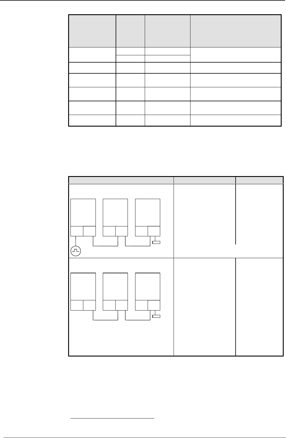
Operating Instructions COMPAX-M / -S
Process coupling using HEDA (Option A1 / A4)
170
Master output
quantites:
P184=
Slave
input
quanti-
ties:
P188=
Can be used in
slave unit
versions:
Settings in master and slave for
adapting the process quantities:
P98 is identical in all units
40 40 CPX 60, CPX 70 P143s=P14340M
(CPX 00 CPX 60, CPX 70) 43 CPX 70
42
(CPX 70)
42 CPX 70 P143s=P143M
43 140* CPX 60, CPX 70 P143s=P143M
(CPX 70) 43 CPX 70
44 140* CPX 60, CPX 70 P143s = 214 = 16384
(CPX 00 CPX 60, CPX 70) 43 CPX 70
45 140* CPX 60, CPX 70 P143s = 214 = 16384
(CPX 00 CPX 60, CPX 70) 43 CPX 70
46
(CPX 00 CPX 60, CPX 70)
42 CPX 70 P143s=P143M
∗
When the encoder position P184=40 is transferred, the encoder position is
transferred into high word and the duration period of the pulses is transferred into
low word to support a duration period measurement in the slave.
If a mixture of application purposes is undertaken, e.g. master P184=44 (nominal
value) and slave with encoder coupling, then the slave must be informed using
P188=140 (in such cases only the high word is processed).
1st unit: Master Slave
COMPAX XX60
COMPAX XX70 (P31=1)
Encoder input
P184=40 (encoder
position+duration
period)
P188=40
COMPAX XX60
COMPAX XX70
(P31=9)
P188=40
(encoder input;
duration period
available)
Coupling of several axes to one
encoder; HEDA distributes the signals
O1/O3
Slave 2Slave 1Master
BUS2/01SSK14SSK15
GBK11
I2 O1/O3 O1/O3
P98 and P143 must have the same
values for master and slave!
Replacing the encoder emulation using
HEDA bus
O1/O3
Slave 2Slave 1Master
BUS2/01SSK14SSK15
O1/O3 O1/O3
Note: There is a time misalignment
between master and slave of 2ms;
Remedy: activate identical program
sets together using "Fast start".
COMPAX XX00
COMPAX XX60
COMPAX XX70
P184=44 (nominal
position value) or
P184=45 (actual
position value)
P188=0
COMPAX XX60
COMPAX XX70
P188=140
Setting P143 =
16384
(¼ of the increments
are always in P143
as quadrupling
occurs during
encoder inputs)
40 P143s: parameter P143 of the slave
P143M: parameter P143 of the master
Permissible
combinations and
required
parameter
settings:
Application
examples:
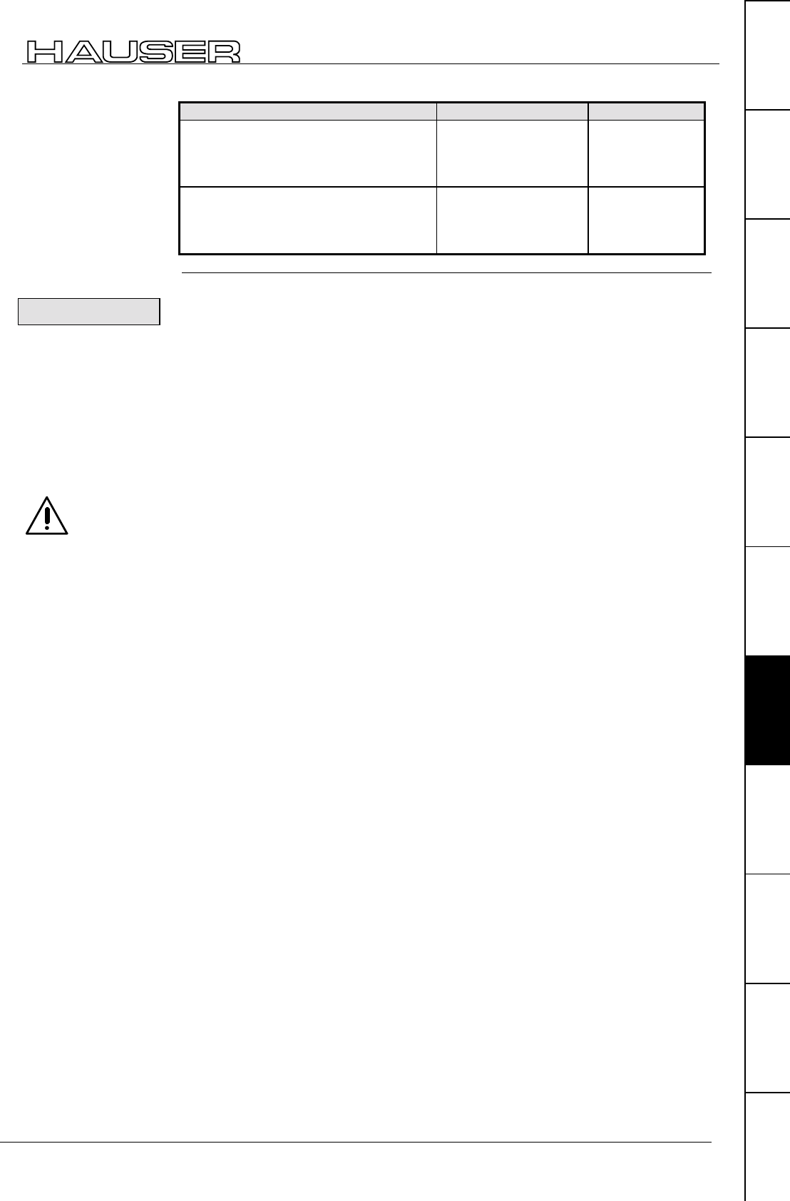
Interfaces
Process coupling using HEDA (Option A1 / A4)
171
Unit
hardware
Connector
assignment / cable
Technical dataConfigurationPositioning and
control functions
Optimization
functions
InterfacesAccessories /
options
StatusParameterError list
1st unit: Master Slave
Coupling of several cams with the
same time base and separate master
or slave oriented label synchronization
(see above)
COMPAX XX70
P184=42 (time base)
P188=42
COMPAX XX70
P188=42
P143s=P143M
Linking of several cams with the same
time base and absolute zero drift
between the axes due to the transfer of
a position value (see above)
COMPAX XX70
P184=43 (scaled
master position)
P188=43
COMPAX XX70
P188=43
P143s=P143M
Only position signals can be completely restored following HEDA transmission
errors . When transmitting velocities, transmission errors can lead to drift
tendencies between the axis positions. For this reason use of the position
values is preferred.
HEDA transmission or synchronization errors are errors E76, E77 and E78.
Synchronization is interrupted with E76, therefore an alignment is implemented
whereby the process position value is aligned in such a manner that a position leap
does not occur.
With E77/E78, the slave attempts to reach the new undisturbed process position
value in order to maintain the reference system.
Transmitting "VC" interrupts the synchronization.
Only activate "VC" when the unit is switched off.
When working with the user terminal BDF2, "VC" is transmitted when the
"Parameter edit" menu is exited.
Position values / position (P184=40/43/44/45): linear interpolation using old
values
Velocity values / frequencies (P184=42/46): retains old value
In cases when P188>0 on the master side, a fixed delay in the associated process
value is implemented, amounting to a total of 2 ms. This ensures that the master
waits until all axes have received the process value. This ensures that all axes,
including the master, continue to process the new nominal values simultaneously.
♦
Except for fast start, no additional I/O's are sent.
♦
There can be only one master on the bus!
♦
The position values for P184=44 and P184=45 are derived independently of the
current positioning operating mode (normal, continuous, reset). They are
obtained from the nominal position value and the actual position value and
made available in 24-bit format, as if with counter channels. This avoids jerky
changes in the start torque (in continuous mode) or when reading the end of the
curve (in reset mode). Only the lower 24 bits of these values are transmitted,
consisting of the resolver value and maximum 256 motor revolutions.
The required cable types are listed on Page 63.
Error handling
Error messages:
E76:
E77/E78:
Note!
Transmission error
procedure:
Synchronizing
process values:
Note:
Note:

Operating Instructions COMPAX-M / -S
Process coupling using HEDA (Option A1 / A4)
172
Please note: the operating instructions (pages 67 - 171) as well as
the application examples (pages 225 - 237) can be found in the com-
plete product manual which is available as PDF file on CD
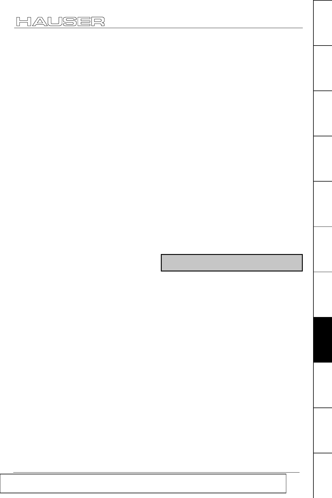
System concept
173
Unit
hardware
Connector
assignment / cable
Technical dataConfigurationPositioning and
control functions
Optimization
functions
InterfacesAccessories /
options
StatusParameterError list
9. Accessories and options
Compact Servo Controller
9.1 System concept
The COMPAX system concept is based on a basic
unit which contains the function-important
components and additional system components.
These can be used to extend a system for your
specific requirements.
The system consists of the following components:
! COMPAX
This contains:
• digital inputs and outputs (PLC interface)
• serial interface (RS232)
• front plate with status and error display
• data record memory
• integrated IGBT final stage
! mains module to produce power voltage (without
transformer); with emergency stop function.
! drive unit (motor, transmission and cable).
! aids for controlling COMPAX using the digital
inputs and outputs.
! interface cable for operating COMPAX via the
serial interface RS232.
! options which support other application areas.
! hand-held terminal for menu-guided configuration
and programming of COMPAX.
! PC software for supported parameter
specification and for creating programs.
Please note: the operating instructions (pages 67 - 171) as well as the application examples (pages
225 - 237) can be found in the complete product manual which is available as PDF file on CD
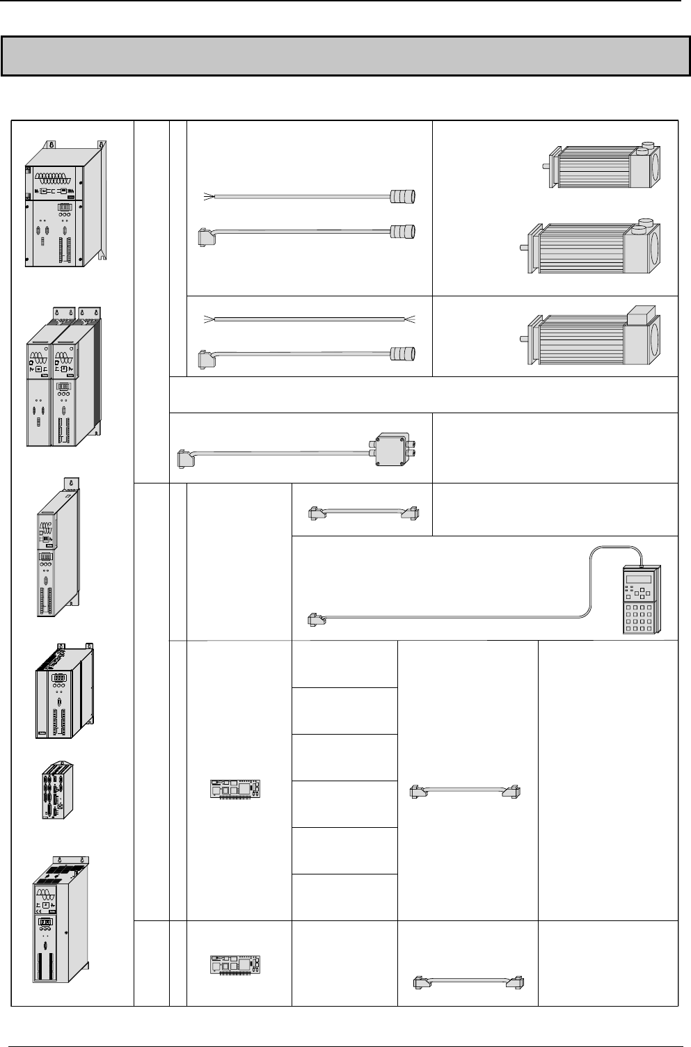
A
ccessories and options COMPAX-M / -S
174
9.2 Overview
The following table shows the COMPAX system components and the relevant associated cables.
Drives
MOK 21 / MOK11 / MOK46
REK 32
MOK 42 / MOK43
REK 32
Interfaces
RS232
To PC or Terminal
Iinitiators: IN HE 521506
RS 485 ASCII / binary
Option F1: 4-Wire
Option F5: 2-Wire
The RS232 -
Other motor types
Interbus-S
Option F2
Profibus
Option F3
CAN Bus
Option F4
HEDA
SSK 1/..
SSK13/...
HDY055..
HDY070..
HDY092..
HDY115..
HJ96..
HJ116..
HDY142..
HJ155
HJ190..
CANopen
Option F8
CS31-System bus
Option F7
initiator set IVD 1/.. for 3 initiators
interface is
available in the
standard device
handheld terminal BDF 2/01
Synchronous motor
bus systems
as plug-in option to further bus
subscribers
as plug-in option to an IPC with Hauser
plug-in board "IPM" for
contouring
COMPAX-M with
Power module NMD
X6 X7
X8
Ready Error
RS485IN OUT
Control
DIGITAL
Status Numbe r
X6
X8 X10
-+Enter
Ready Error
RS232
Input
Output
Test
Control
X9 X11
Value
Power Supply COMPAX- M
Status
Number
X6
X8 X10
-
+
Enter
Ready Error
RS232
Input
Output
Test
Control
X9 X11
Value
DIGITAL
COMPAX P1XXM
COMPAX-M
Status Number
X6
X8 X10
-+Enter
Ready Error
RS232
Input
Output
Test
Control
X9 X11
Value
COMPAX-S
COMPAX 25XXS
COMPAX 45XXS
COMPAX 85XXS
X11X9
Input
Output Output
Input
Test Control
X10
X6
X8
RS232
Ready Error
ENTER+-
Value
Status Number
COMPAX-S
DIGITAL
Digital
COMPAX-M
X6 X7
X8
Ready Error
RS485IN OUT
Control
Status Number
X6
X8 X1 0
-+Enter
Ready Error
RS232
Input
Output
Test
Control
X9 X1 1
Value
COMPAX 35XXM
RDump
Input
+-
Fieldbus InEncoder
Input / Output Resolver Fieldbus Out Limit Switch
24 V DC
H2
H1
RS232 X6X5X13
X12 X17
X19
X2 X1 X4 X3
X14 X15
HEDA Out HEDA In
L1 N PE U V W PE + -
Motor Brake
PE
230 V AC
COMPAX - SL
X7
COMPAX 10XXSL
HEDA
Option A1
COMPAX 1000SL:
Option A4
BUS 2/01:Bus termination
SSK14/.. : IPM - COMPAX
COMPAX - COMPAX
SSK15/.. : COMPAX-Master
- COMPAX-Slave
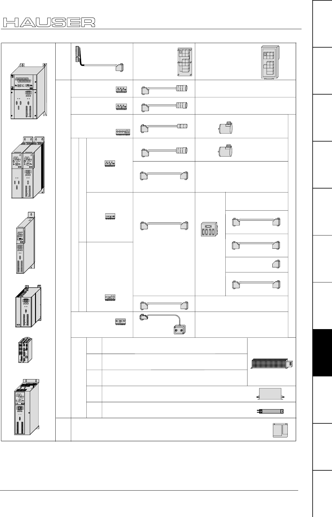
Overview
175
Unit
hardware
Connector
assignment / cable
Technical dataConfigurationPositioning and
control functions
Optimization
functions
InterfacesAccessories /
options
StatusParameterError list
Options
Absolute encoder
Interface A1
Encoder
Channel 1
Encoder-
Input I 2
(with cable connection)
Channel 2
Encoder-
EAM 4/01 SSK 7/..
distributor
to the
Encoder distributors
channel 1 incoming
SSK 7/..
Channel 1 relaying
SSK 7/..
Channel 2 output
SSK 4/..
SSK 7/.. Direct to an encoder input
e.g. to COMPAX-M
SSK 7/.. Direct to encoder simulation of
COMPAX oder SV Drive
GBK 11/..
GBK 1/.. Absolute encoder
STEGMANN
AA100
Encoder Litton
G71SSLDBI-
4096-151-050BX
D/A - Monitor D1 (12 Bit)
COMPAX
Monitor
DA0 DA1
ASS 1/01 to oscilloscope
Interfaces
SSK 6/..
BDF 1/02 BDF 1/03
Operating panel
Bus termination
BUS 1/01
PC-
Software
COMPAX ServoManager with:
ParameterEditor and
ProgrammEditor
CamEditor for COMPAX XX70
Ballast resistor BRM 4/..witht 1.5m cable
optainable in 3 ratings for connection to
the power module NMD20
Analogue output of
intermediate values
Ballast resistors
COMPAX
45XXS/
85XXS
COMPAX
2500S
Ballast resistor BRM 5/01 with 0.3m cable
for connection to COMPAX 25XXS
(without cable
connection)
Encoder-
Input I 4
SinCos
Option S1/S2
GBK 16/.. SinCos imstalled in the motor
EncoEer-
simulation
Option I 3
COMPAX
35XXM NMD20
Ballast resistor BRM 6/01 with 1.5m cable
for connection to COMPAX 45XXS / COMPAX 85XXS
Ballast resistor BRM 7/01 with 1.5m cable
for connection to COMPAX 35XXM
COMPAX-M with
Power module NMD
X6 X7
X8
Ready Error
RS485IN OUT
Control
DIGITAL
Status Number
X6
X8 X10
-+Enter
Ready Error
RS232
Input
Output
Test
Control
X9 X11
Value
Power Supply COMPAX-M
Status
Number
X6
X8 X10
-
+
Enter
Ready Error
RS232
Input
Output
Test
Control
X9 X11
Value
DIGITAL
COMPAX P1XXM
COMPAX-M
Status Number
X6
X8 X10
-+Enter
Ready Error
RS232
Input
Output
Test
Control
X9 X11
Value
COMPAX-S
COMPAX 25XXS
COMPAX 45XXS
COMPAX 85XXS
X11X9
Input
Output Output
Input
Test Control
X10
X6
X8
RS232
Ready Error
ENTER+-
Value
Status Number
COMPAX-S
DIGITAL
Digital
COMPAX-M
X6 X7
X8
Ready Error
RS485IN OUT
Control
Status Number
X6
X8 X1 0
-+Enter
Ready Error
RS232
Input
Output
Test
Control
X9 X1 1
Value
COMPAX 35XXM
RDump
Input
+-
Fieldbus InEncoder
Input / Output Resolver Fieldbus Out Limit Switch
24 V DC
H2
H1
RS232 X6X5X13
X12 X17
X19
X2 X1 X4 X3
X14 X15
HEDA Out HEDA In
L1 N PE UVWPE+-
Motor Brake
PE
230 V AC
COMPAX - SL
X7
COMPAX 10XXSL
These Options are not available for COMPAX 1000SL
COMPAX
1000SL
Ballast resistor BRM 8/01 with 0.25m cable
for connection to COMPAX 10XXSL
SinCos
Option S3 für
Linearmotoren
GBK 18/.. SinCos installed in the motor
Operating panel
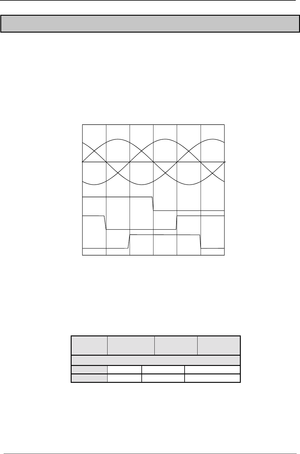
A
ccessories and options COMPAX-M / -S
176
9.3 Motors
Suitable motors are described in the motor catalogue (Article No.: 192-
060011)!
COMPAX also supports the operation of linear motors. For this, COMPAX requires
option S3 (interface to linear encoder and Hall sensor; assignment X12 see Page
46).
Conditions regarding the linear motor:
♦
3 phase synchronous linear motors with:
• sine-cosine linear encoder (1Vss).or TTL (RS422)
• digital Hall sensor commutation (5V) with following signal sequence:
Hall 2
Hall 3
Hall 1
Phase
V-U
Phase
U-W
Phase
W-V
The depicted signal sequence applies for positive direction.
Only the modes P212=7 and P212=11 are presently available as reference modes
for linear motors!
For highly dynamic and precise applications, we provide the linear motor LXR,
which can be operated with COMPAX 25XXS or COMPAX 10XXSL (with the S3
option and GBK18 and GBK20 cable). Ask for our leaflet.
When operating the linear motor LXR, reduced norminal and peak currents apply to
COMPAX:
Unit
COMPAX ..
Nominal
current [Aeff] Peak current
[Aeff] <5s Power [kVA]
with mains supply: 230V AC
10XXSL 2.1 4.2 0.8
25XXS 4.1 8.2 1.4
EMD motors
Linear motor:
Note concerning
the reference mode:
Linear motor LXR
Note:
HAUSER linear actuators
177
Unit
hardware
Connector
assignment / cable
Technical dataConfigurationPositioning and
control functions
Optimization
functions
InterfacesAccessories /
options
StatusParameterError list
9.4 HAUSER linear actuators
The HAUSER "HLEc" linear unit is available with various cross sections:
♦
HLE80C cross section: 80 mm x 80 mm up to 6m long
♦
HLE100C cross-section: 100 mm x 100 mm up to 7m long
♦
HLE150C cross-section: 150 mm x 150 mm up to 10m long
Highly dynamic, modular linear axis "HPLA" with toothed belt drive or rack-
and-pinion drive:
♦
HPLA80: cross section: 80 mm x 80 mm
up to 50m for rack-and-pinion, up to 20m for toothed belt
♦
HPLA120: cross section: 120 mm x 120 mm
up to 50m for rack-and-pinion, up to 20m for toothed belt
♦
HPLA180: cross section: 180 mm x 180 mm
up to 50m for rack-and-pinion, up to 20m for toothed belt
Electric cylinder ET: with 50 - 1500 mm stroke. Tensile and shear forces up to
21000 N
Vertical actuators with toothed belt: up to 2500mm stroke; up to 100kg
payload
The attached transmissions are available with ratios of 3:1, 5:1, 7:1, 10:1 and 25:1.
Please contact us if you require more information.
If you are using, e.g. a rack-and-pinion drive, toothed belt drive or spindle drive,
you can obtain the necessary initiators and initiator connectors and cable from us.
We can also supply you with retaining material on request.
Initiator set

A
ccessories and options COMPAX-M / -S
178
9.5 Data interfaces
9.5.1 RS232
Use the RS232 interface, fitted as standard in COMPAX, to connect COMPAX with
a PC or terminal. This can then be used to operate COMPAX. The SSK1/..
interface cable is available as a connecting cable (for available lengths, see Page
206).
9.5.2 Bus systems
The bus systems are options which you can select to use or not. They require an
additional board to be fitted in COMPAX. The connection is located on the mains
module or, in COMPAX-S and COMPAX 35XXM, directly on the unit.
The controllers, connected to the mains module or COMPAX 35XXM, are already
connected via the flatband cable available in the system network.
9.5.2.1 Interbus-S / Option F2
You will find an object directory in the special documentation. The connection
arrangement is based on the specifications of 2-conductor remote bus.
9.5.2.2 RS485 / Option F1/F5
The RS485 interface is described in the special documentation. 2 different options
are available:
♦
F1: 4 wire RS485F5: 2 wire RS485
9.5.2.3 Profibus / option F3
The Profibus is described in the special documentation. Functions:
♦
Sinec L2-DP and FMS
♦
1.5M Baud
♦
Communication with Simatic S7 is supported by special function modules.
9.5.2.4 CAN - Bus / Option F4
The Profibus is described in the special documentation. Functions:
♦
BasicCAN
♦
up to 1M Baud
♦
CAN protocol as per specification 1.2
♦
Hardware as per ISO/DIS 11898
9.5.2.5 CANopen / Option F8
♦
Protocol as per CiA DS 301.
♦
Profile CiA DS 402 for drives.
9.5.2.6 CS31system bus / Option F7
♦
COMPAX – ABB – interface.
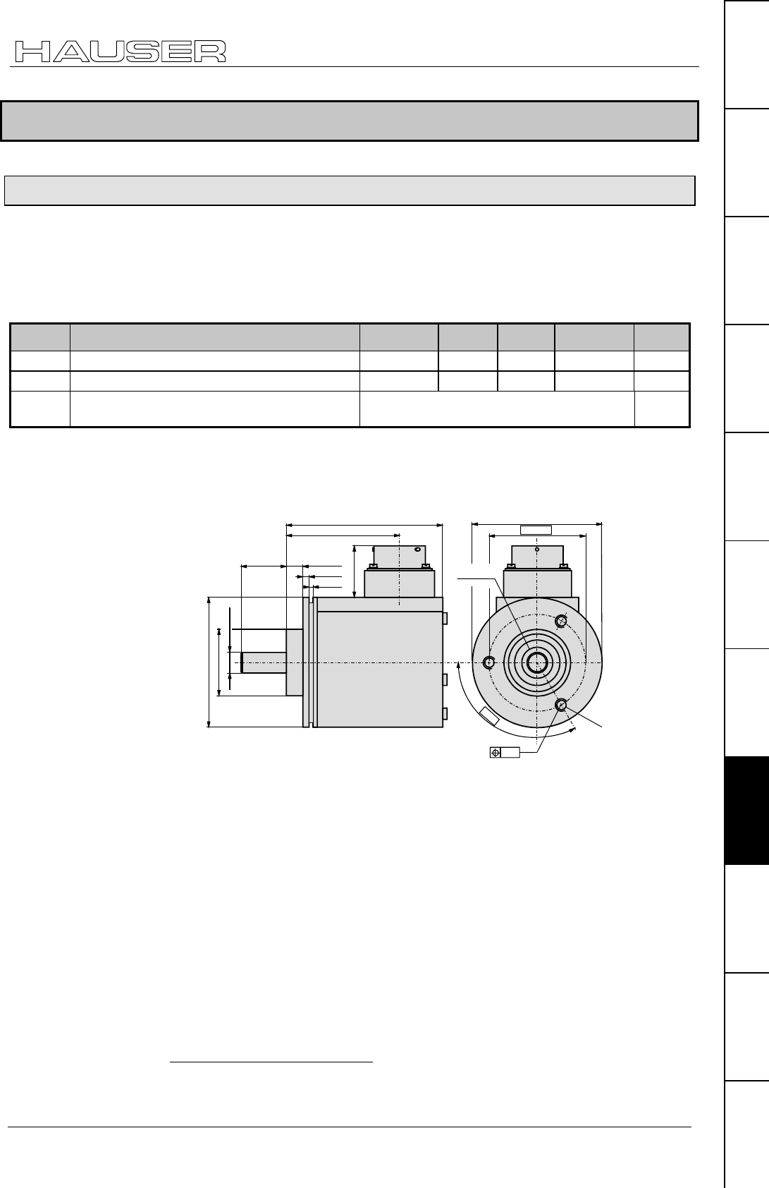
Process interfaces
179
Unit
hardware
Connector
assignment / cable
Technical dataConfigurationPositioning and
control functions
Optimization
functions
InterfacesAccessories /
options
StatusParameterError list
9.6 Process interfaces
9.6.1 Encoder interface
The encoder interface option E2 (E4)41 enables the connection of an external
incremental encoder (such as: Litton encoder G71SSLDBI-4096-151-05BX). Use
this to synchronize COMPAX with an external speed using the "SPEED SYNC"
command. The encoder pulses per revolution and the translational travel per
encoder revolution are set via the COMPAX parameters P143 and P98.
No. Meaning Unit Minimu
m value Default
value Maximum
value Valid
from...
P98 Travel of axis per encoder revolution corresp. P90 00.0000000 4 000 000 VC
P143 Encoder pulses per revolution (channel 1) 120 4096 2 000 000 VC
P146 Resolution of encoder emulation (channel 2)
(for permanent SinCos setting, see Page 183)
=0: 1024 =8: 512 VC
♦
RS422 interface ♦5V supply;
♦
120-10 000 increments/revolution (fmin: 4 kHz; fmax: 500 kHz).
Dimensional diagram for Litton encoder G71SSLDBI-4096-151-05BX:
63.5±0.1
47.625
120°
Shaft seal
∅
∅∅
∅0.2
26
2.65-0.25
2.65-0.25
7.5+0.25
∅
∅∅
∅ 9.52-0.008
∅
∅∅
∅ 31.75 -0.01
∅
∅∅
∅ 58.87-0.25
22.2±0.5
46.35±0,2
68 max
for screw:
10-32 UNF-2B
thread 4,8 deep
41 Does not apply for COMPAX 1000SL. COMPAX 1000SL allows to configure the
generally available signal interface either as encoder input or as encoder emulation (See
page 61).
Technical data:
Dimension diagram:
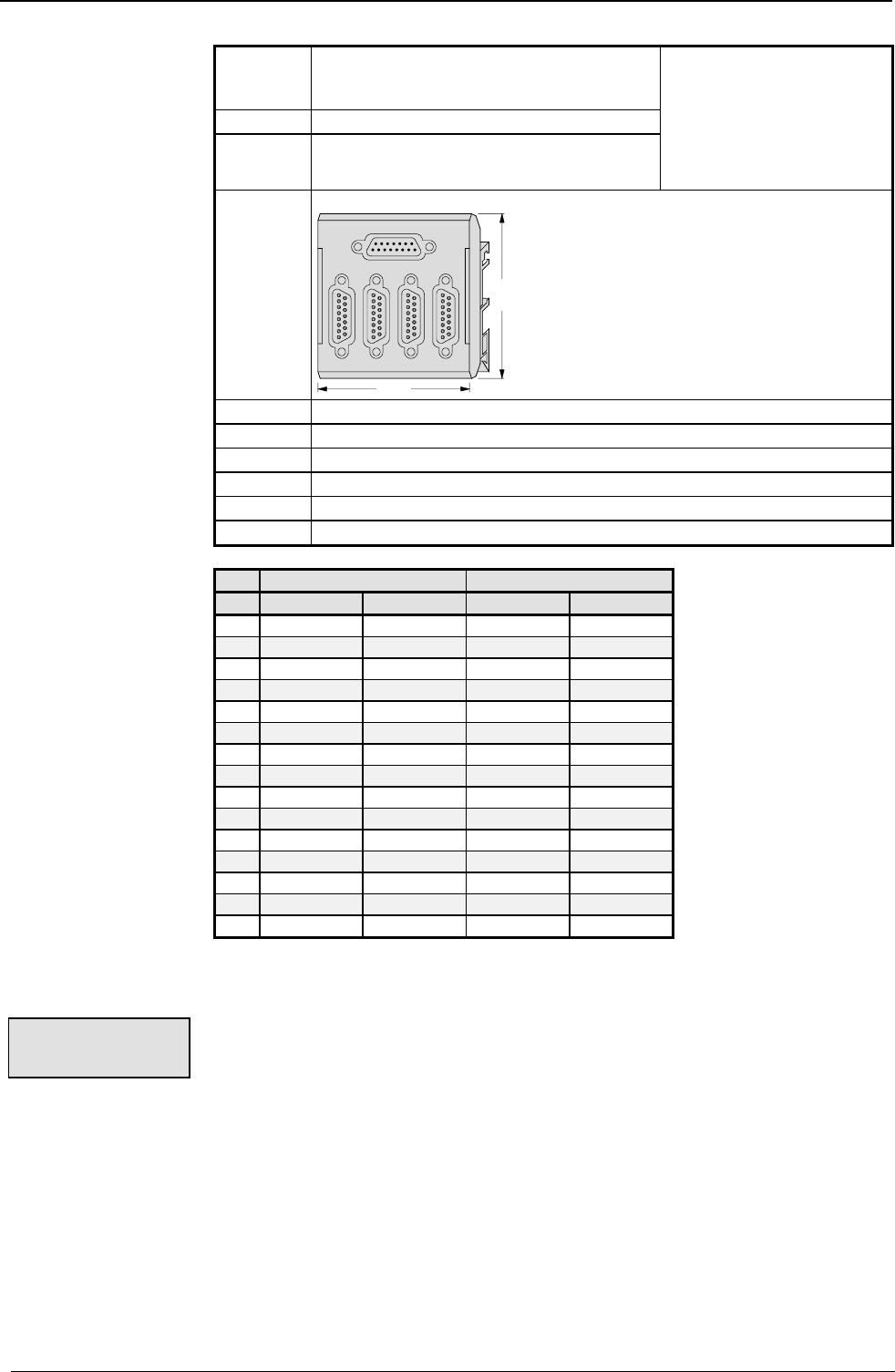
A
ccessories and options COMPAX-M / -S
180
E2 Encoder input module with line terminator for
individual connections; not for creating an
encoder bus.
E3 E3: Encoder emulation
E4 Encoder input module without line terminator
for creating an encoder bus.
Not for COMPAX 1000SL:
With COMPAX 1000SL, the
signal interface usually
present can be configured
either as an encoder input or
encoder simulation (see Page
61.
EAM4/01 Encoder distributor for creating an encoder bus.
Design:
70mm
80mm
BUS1/01 Bus termination for encoder distributor EAM4/01.
BUS6/01 Bus termination for encoder - COMPAX 1000SL connection
GBK11/.. Encoder cablefor connecting COMPAX with an encoder.
SSK7/.. Connector cable between encoder distributors or from an encoder emulation.
SSK4/.. Connector cable between COMPAX and encoder distributor.
SSK17/.. Connector cable between COMPAX 1000SL (encoder emulation) – COMPAX
Channel 1 Channel 2
Pin X1: IN X2: OUT X3: IN X4: OUT
1 Screen Screen Screen Screen
2NC N1 NC N2
3NCB1NCB2
4NC 1A NC A2
5N1NCN2NC
6B1 NC B2 NC
71A NC A2 NC
8+5V NC +5V NC
9 NC N1/ NC N2/
10 NC B1/ NC B2/
11 NC O1/ NC A2/
12 N1/ NC N2/ NC
13 B1/ NC B2/ NC
14 O1/ NC A2/ NC
15GNDNCGNDNC
Applications with encoder:
Encoder COMPAX
♦
Cable: GBK 11/..
♦
Encoder input module E2 with line terminator, or for
♦
COMPAX 1000SL: Configured as encoder input (P144=4; P146=0) and with bus
termination BUS 6/01 (sits as an intermediate connector on X13)
SV drive COMPAX
♦
Cable: SSK 7/..
Note! Note direction.
cable in: SV drive
cable out: COMPAX
♦
Encoder input module E2 with line terminator, or for
♦
COMPAX 1000SL: Configured as encoder input (P144=4; P146=0) and with bus
termination BUS 6/01 (sits as an intermediate connector on X13).
Encoder module
and accessories:
Assignment of
EAM4/01
(corresp. X13)
Individual
connections
Depth: 40 mm without mating connector
The module is engaged on the terminal
bus bar.
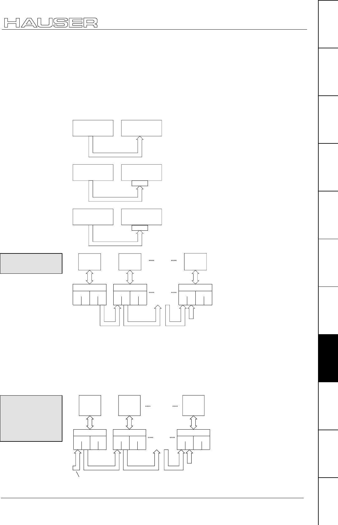
Process interfaces
181
Unit
hardware
Connector
assignment / cable
Technical dataConfigurationPositioning and
control functions
Optimization
functions
InterfacesAccessories /
options
StatusParameterError list
COMPAX COMPAX
♦
Cable: SSK 7/.. or SSK17 (see principal diagrams below)
Note! Note direction.
cable in: COMPAX with encoder emulation
cable out: COMPAX with encoder input
♦
Encoder simulation E3 for COMPAX (master) (in COMPAX 1000SL encoder
simulation configured)
♦
Encoder input module E2 for COMPAX (slave) (in COMPAX 1000SL encoder
input configured and with bus termination BUS 6/01)
cable in
cable out
X13
COMPAX
(not COMPAX 1000SL)
X13 E3 E2
SSK7
COMPAX
(not COMPAX 1000SL)
cable in
cable out
X13
COMPAX
(not COMPAX 1000SL)
X13 E3
SSK7
COMPAX 1000SL
(Encoder emulation)
Bus6/01
cable in
cable out
X13
COMPAX 1000SL
(Encoder emulation)
X13
SSK17
COMPAX 1000SL
(Encoder emulation)
Bus6/01
cable in
cable out
Other
slaves
cable in
cable out
cable in
cable out
Other
encoder
distributors
Slave 1
X13
Slave n
X13
Master
X13
BUS1/01
Bus ter-
mination
IN OUT IN OUT
X1 X2 X3
Channel 1 Channel 2
X4
EAM4/01 X5
IN OUT IN OUT
X1 X2 X3 X4
EAM4/01 X5
IN OUT IN OUT
X1 X2 X3 X4
EAM4/01 X5
SSK4 SSK4 SSK4
Channel 1Channel 2 Channel 1 Channel 2
E3 E4 E4
Requirements per COMPAX:
• one encoder distributor .................................................................. EAM 4/01
• one cable for the COMPAX and encoder distributor connection ... SSK 4/..
• one bus cable for connecting the encoder distributors .................. SSK 7/..
♦
Encoder simulation in the master................................................... E3
♦
Encoder input module in each slave .............................................. E4
♦
Bus terminator................................................................................ BUS 1/01
cable in
cable out
cable in
cable out
Other
encoder
distributors
cable in
cable out
cable out
X13 X13 X13
BUS1/01
Bus ter-
mination
SSK4 SSK4 SSK4
IN OUT IN OUT
X1 X2 X3
Channel 1 Channel 2
X4
EAM4/01 X5
IN OUT IN OUT
X1 X2 X3 X4
IN OUT IN OUT
X1 X2 X3 X4
Channel 1Channel 2 Channel 1 Channel 2
E4E4E4
EAM4/01 X5 EAM4/01 X5
COMPAX –
COMPAX (both not
COMPAX 1000SL)
COMPAX (not
COMPAX 1000SL) –
COMPAX 1000SL
COMPAX 1000SL –
COMPAX 1000SL
Encoder bus
with COMPAX
Encoder bus
with encoder or
encoder
emulation in SV
drive
SSK7 SSK7SSK7
SSK7SSK7SSK7
From encoder (GBK11) or SV drive encoder emulation (SSK7)
Additional
COMPAX
COMPAX
COMPAX
COMPAX
(configured in
COMPAX 1000SL
)
(configured in
COMPAX 1000SL
)
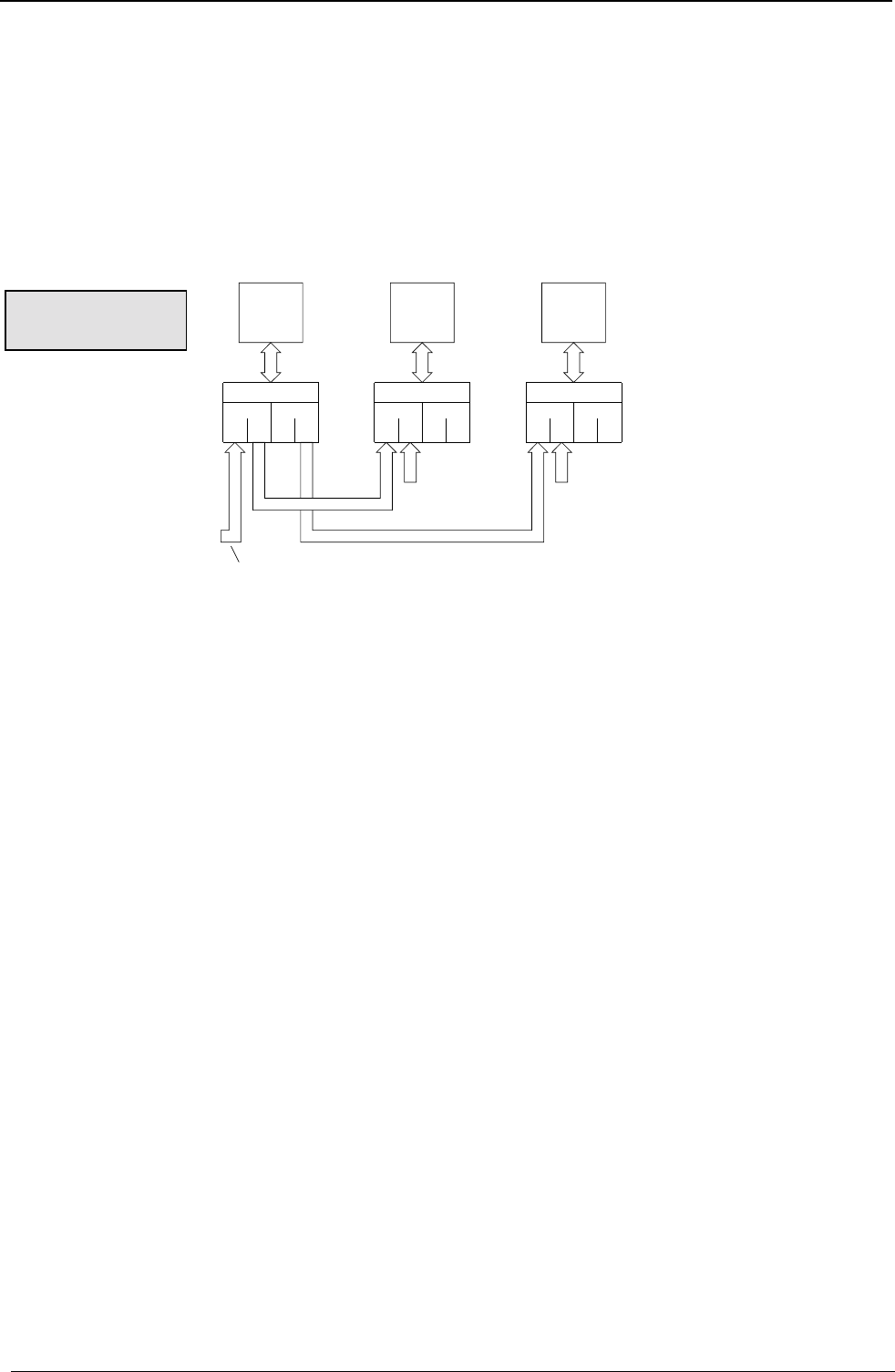
A
ccessories and options COMPAX-M / -S
182
The following are required:
♦
per COMPAX
• one encoder distributor .................................................................. EAM 4/01
• one cable for the COMPAX and encoder distributor connection ... SSK 4/..
• one bus cable for the connection between the encoder distributors... SSK7/..
♦
Encoder input module .................................................................... E4
♦
Bus terminator................................................................................ BUS 1/01
♦
For the encoder: encoder cable .................................................. GBK11/..
♦
For the SV drive: Cable: ................................................................ SSK7/..
cable in
cable out
cable in
cable out
cable out
X13 X13 X13
No. 1No. 2No. 3
BUS1/01
Bus ter-
mination
IN OUT IN OUT
X1 X2 X3
Channel 1 Channel 2
X4
EAM4/01 X5
IN OUT IN OUT
X1 X2 X3 X4
EAM4/01 X5
IN OUT IN OUT
X1 X2 X3 X4
EAM4/01 X5
SSK4 SSK4 SSK4
Channel 1 Channel 2 Channel 1 Channel 2
BUS1/01
Bus ter-
mination
E3&
E4 E4 E4
♦
COMPAX 1 and COMPAX 2 receive the signals from one encoder.
♦
COMPAX 3 receives the actual COMPAX 1 value concerning its emulation.
The following are required:
♦
per COMPAX
• one encoder distributor................................................................ EAM 4/01
• one cable for the COMPAX and encoder distributor connection SSK 4/..
♦
3 bus cables .................................................................................. SSK 7/..
♦
2 bus terminators .......................................................................... BUS1/01
Encoder module:
♦
COMPAX 1 (not possible with COMPAX 1000SL as there is only 1 encoder channel present!):
• Encoder input module.................................................................. E4
• Encoder emulation ...................................................................... E3
♦
COMPAX 2, 3:
• Encoder input module.................................................................. E4
• Encoder cable: ............................................................................ GBK11/..
Encoder bus
mixed
From encoder (GBK11) or SV drive encoder emulation (SSK7)
SSK7
COMPAXCOMPAXCOMPAX
SSK7
(configured in
COMPAX 1000SL
)
(configured in
COMPAX 1000SL)
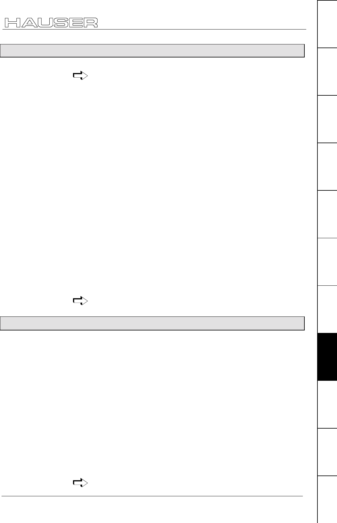
Process interfaces
183
Unit
hardware
Connector
assignment / cable
Technical dataConfigurationPositioning and
control functions
Optimization
functions
InterfacesAccessories /
options
StatusParameterError list
9.6.2 Absolute value sensor (A1)
The option A1 cannot be used for COMPAX 1000SL.
When using option A1 (the absolute value sensor interface), the reference travel
(find machine zero) normally required in normal mode after switching on is not
required. The reference travel is then only required during start-up. The current
read sensor position can be found in Status S12.
Supported absolute value sensors
The following Stegmann - absolute value sensors types are supported:
♦
AG100MS/GRAY 4096/4096
or
♦
AG626XSR 4096/4096.
♦
Supply voltage: 24V ±10%.
♦
Sensing code: grey code, single step.
♦
Direction of counting: in clockwise direction when looking at the shaft: rising.
♦
Data interface: RS422 /24 bit data format (starting with: MSB).
♦
Cycle frequency: 100 kHz.
Enable absolute value sensor input
When using equipped A1 option (if this is not already being executed by HAUSER),
the absolute value sensor input is enabled using parameter P206. Meaning:
P206 ="1" absolute value sensor input enabled.
♦
Only activate the absolute value sensor input if an absolute value sensor has
been connected correctly and physically.
♦
Continuous mode is not permitted when the absolute value sensor is active.
Option A1 also contains the HEDA interface.
Further information on the value range of S12 can be found on Page 79
9.6.3 High resolution SinCos sensor system (S1/S2)
COMPAX uses option S1 to support the high-resolution, optical motor position
recording process via the Stegmann SinCos sensor system (as a substitute for the
motor position recording via resolver).
SinCos single-turn:Type SRS50
SinCos multi-turn: Type SRM50
A SinCos sensor provides the following improvements.
♦
Better concentricity.
♦
Position recorded with greater absolute accuracy:
Resolver:± 0.25°
SinCos: ± 0.005°
♦
Resolution of motor speed:
Resolver:16/12 bit (speed-dependent ; 12 bit at higher speeds)
SinCos: 19 bit over the whole range of motor speeds.
♦
Less noise at a higher dynamic level via the motor speed resolution.
• With the SinCos multi-turn you also get economical absolute value sensor
function.
4096 motor revolutions detected absolute.
Further information on the value range of S12 can be found on Page 79
Technical data
Note!
Note
A
ccessories and options COMPAX-M / -S
184
SinCos multi-turn with programmable transmission factor
When using a SinCos multi-turn, you can use the S2 option to adapt the range of
the absolute position S12 to your application via a transmission factor. S12 then
always contains the position value referenced to the reset path P96.
Positioning is still implemented with reference to the actual value in Status S1.
SinCos multi-turn records an absolute position of 4096 rotations.
In applications such as controlling a round table via a transmission, the position of
the table cannot be determined very accurately because 4096 rotations usually
signifies several rotations of the table.
By specifying the transmission factor P96 (ratio of motor : table), the absolute
position S12 is reset to 0 after a table rotation. After "Power on" and after an error
has occurred, S12 is transferred as the actual value (S1=S12).
The function is switched on via P206="1".
No. Meaning Unit Minimum
value Default
value Maximum
value Valid
from...
P96 Transmission factor for the reset path of S2 –
option ("0": no reset function)
-0 0 2048 VC
P206 Enabled absolute value sensor input or the
reset functions of the S2 option
="1": absolute value sensor input enabled or
reset function switched on.
VP
Please note
♦
Set P1=0. Using P212=10 (see Page 80) you can still select the machine zero
point as required.
This function does not affect the actual positioning process.
Example:P96=10 (sensor revolutions); P83=40 000µm (40mm)
After POSA 450 and then POSA 0, the drive reverses by 450 mm (and
not just 50 mm).
To execute a positioning process within the reset path after traveling in
one direction for a long time, evaluate S12.
E.g.: required position within the reset path = 10 mm
V1=10-S12
POSR .V1
9.6.4 Option S3 for linear motors.
See Page 176
S2 – option:
Standard:
Note!
Process interfaces
185
Unit
hardware
Connector
assignment / cable
Technical dataConfigurationPositioning and
control functions
Optimization
functions
InterfacesAccessories /
options
StatusParameterError list
9.6.5 HEDA interface
HEDA using option A1 (e.g. A4 for COMPAX 1000SL) for COMPAX XX00
and the interpolation module IPM as master,
or
for a COMPAX – COMPAX –coupling with the unit variants COMPAX
XX00, COMPAX XX60 and COMPAX XX70, see from Page 168).
Implementing tracking and contouring tasks with the HAUSER interpolation module
(IPM) for PCs and industrial PCs.
Communication occurs via the HEDA interface, a rapid synchronous serial
interface.
Functional scope of the IPM and COMPAX network:
!contours can be stored for up to 9 axes with up to 100000 points.
!16 zero-related digital outputs.
!Exchange of data between 9 axes within 1ms (setpoint values, auxiliary functions,
position, lag error, speed, torque)
!Freely programmable inputs and outputs
(Once enabled via P221, P222 and P225, and allocation of outputs to HEDA via
P245 and P245; see Page 139).
!internal data record memory can still be used to its full extent
!can be independently operated as a single axis positioning system
♦
Physical transfers:
• RS485 level (counter-cycle driver);
• DC decoupled using an optical coupler;
• Cycle frequency: 5 Mbit/s.
Working with the HEDA interface is described from Page 168, where
used with the interpolation module IPM, a special manual is available!
9.6.6 D/A monitor (D1) (option not available with COMPAX 1000SL)
♦
The D/A monitor offers you the option of outputting COMPAX internal
measurement and intermediate parameters in the form of analogue voltage in
the range of ±10V. For description, see Page 58.
A
ccessories and options COMPAX-M / -S
186
9.6.7 Analogue speed specification (E7) (option not available with COMPAX 1000SL)
Option E7 "Analogue speed specification" is available with COMPAX
XX6X "Electronic transmissions" and COMPAX XX70 "Cam controller".
Exception:
In addition, E7 can be used with COMPAX XX00 to implement an external
speed specification with the command "SPEED SYNC"; see Page 99
The "Encoder input" option (E2 or E4) cannot be used at the same time as
E7.
Using option E7, you can specify a nominal speed value via connector X13 as
analogue voltage in the range -10V to +10V. Use 2 digital inputs (PLC level), to
define a nominal speed value of 0 and to initiate a change in the rotational
direction.
The following configuration data must therefore be assigned permanent values:
P80 = "16" (general drive).
P90 = "1" (mm unit).
P83 = 100000 µm (travel per motor revolution).
P93 = "4" (speed control mode).
P143 = 600 000
P144 = "7" (analogue speed specification).
P35 = "1" (transmission factor 1) (I15="0")
I16 = "1" (external nominal value is valid)
These parameters influence the interrelation between voltage and speed; they
must therefore be specified and fixed. Specify the required speed directly in P98 in
min-1 when input voltage is +10V.
Linearity error: <1%
Amplification error: <5% (you can compensate for these with P98).
Offset: <15 mV
Temperature drift: 100 ppm/K
Connector X13:
Pin X13 or
EAM4/01 X1:
(encoder assignment)
COMPAX-
Input I
Output O
Signal Circuit proposal
6 (B1) A +15V <10 mA
7 (O1) E UE
13 (B1\) A -15V <10 mA
15 (GND) A GND
14 (O1\) E UE\ Bridge to 15 (GND)
5 (N1) E Enable "1" for enable
"0" ≡ nominal digital
value 0
12 (N1\) E Direction of
rotation
"1" for positive direction
of rotation
1 Screen
Level on the "Enable" and "Direction of rotation" inputs: 5.5V...30V = "1".
UE and UE\ is a differential input. Actively assign UE\ to a potential (e.g. to
GND).
Only in COMPAX
XX6X and
COMPAX XX70
Configuration:
Accuracy
Connection
assignment
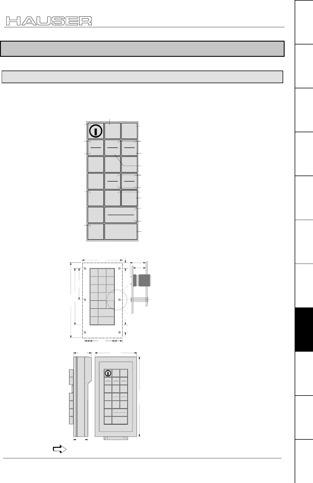
Accessories
187
Unit
hardware
Connector
assignment / cable
Technical dataConfigurationPositioning and
control functions
Optimization
functions
InterfacesAccessories /
options
StatusParameterError list
9.7 Accessories
9.7.1 External control panel (not available for COMPAX 1000SL)
Use the control panels to control COMPAX via the digital inputs. They contain the
following functions:
Release
TEACH
Search
machine
zero
Move to
machine
zero
Move to
real zero
Break
block
TEACH
real zero point
TEACH
block
Error/
warning/
quit
No error
No
warning
I7 / I8
O7 / O8
JOG+
JOG-
START
Ready for
START
Stop block
TEACH
ZERO TEACH
HOME
OK
QUIT
NO
WARNING
QUIT
NO
ERROR
I7
O7
I8
O8
ZERO JOG+ JOG-
START
READY
BREAK STOP
The control panel is available for front plate installation or with housing.
86.0 19.5
15
173
57.80
8.36 14.10
134.0
74.16
14.32
12.34
35
44
195
TEACH
ZERO TEACH
HOME
OK
QUIT QUIT
NO
WARNING
NO
ERROR
I7
O7
I8
O8
ZERO JOG+ JOG-
START
READY
BREAK STOP
101
The control panels are connected with COMPAX via the cable SSK6/..
BDF1/02: for front
plate installation
BDF1/03: with
housing
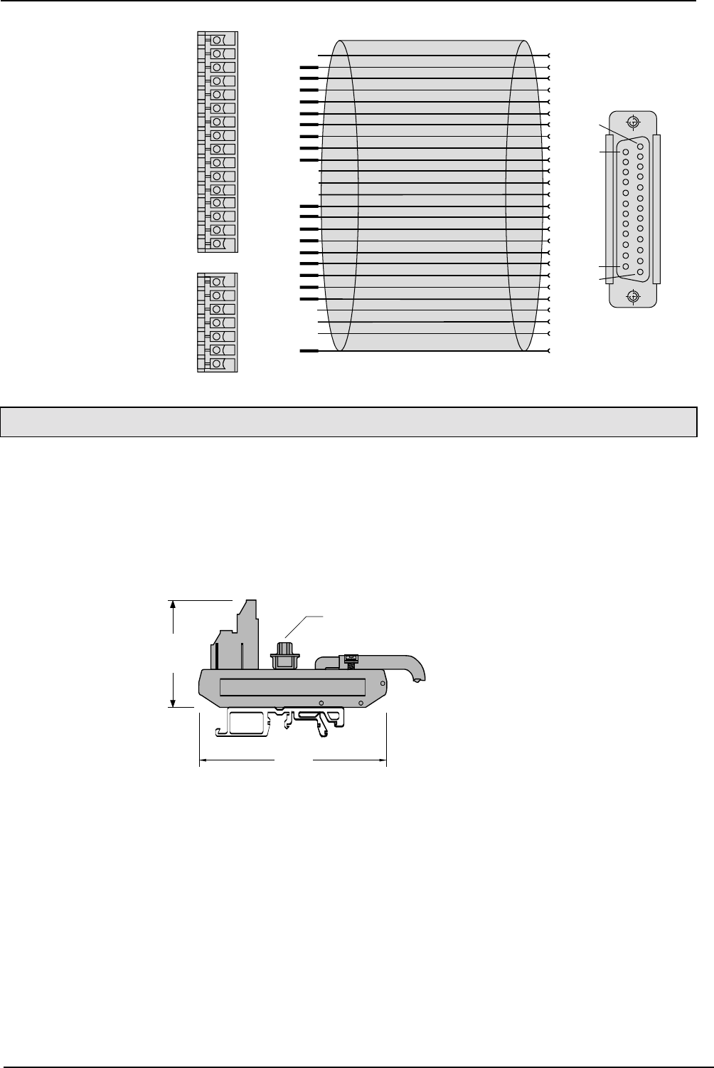
A
ccessories and options COMPAX-M / -S
188
1
2
3
4
5
6
7
8
9
10
11
12
13
14
15
16
17
18
19
20
21
22
23
24
25
X8/9
X8/10
X8/11
X8/12
X8/13
X8/14
X815
X8/16
X9/2
X9/1
X8/1
X8/2
X8/3
X8/4
X8/5
X8/6
X8/7
X8/8
X9/7
Cable KiYCY 25x0,14
X8
X9
16 (O8)
15(O7)
14(O6)
13(O9)
12(O8)
11(O3)
10(O2)
9(O1)
8(I8)
7(I7)
6(I6)
5(I5)
4(I4)
3(I3)
2(I2)
1(I1)
7(Shield)
6
5
4
3
2(GND)
1(+24V)
MC1.5/7-ST-3.81
MC1.5/16-ST-3.81
1
13
14
25
BDF1
D-socked board
DB25 S 0671
white
brown
green
yellow
grey
pink
blue
red
black
violet
grey/pink
red/blue
white/green
brown/green
white/yellow
yellow/brown
white/grey
grey/brown
white/pink
pink/brown
white/blue
brown/blue
white/red
brown/red
white/black
9.7.2 Terminal module for COMPAX 1000SL (EAM)
The terminal module EAM3/.. is used for the onward wiring of the COMPAX
1000SL connector X19 (physical inputs / outputs, ...) to a terminal series and a
Sub-D connector.
The module can be fixed in the control cabinet to an installation rail with a mounting
rail.
The terminal module EAM3/.. contains the cable for connecting with COMPAX
1000SL.
Available lengths of connection lead: 1m; 2.5m; 5m
91 mm
80mm
45mm
Top hat rail
sub-D plug
Width:
Terminal assignment
The terminal assignment corresponds to the pin assignment on X19.
Wiring plan and
assignment of
SSK6/..
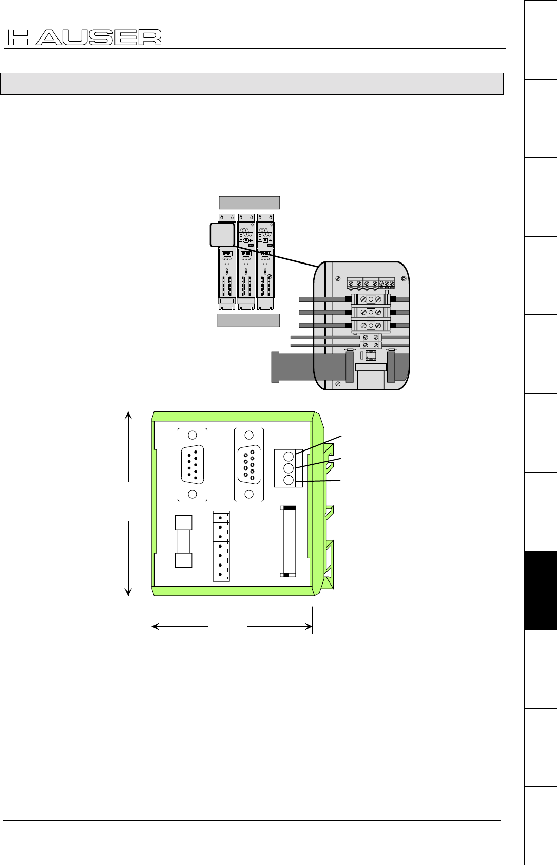
Accessories
EAM5/01: DC feed for COMPAX-M
189
Unit
hardware
Connector
assignment / cable
Technical dataConfigurationPositioning and
control functions
Optimization
functions
InterfacesAccessories /
options
StatusParameterError list
9.7.3 EAM5/01: DC feed for COMPAX-M
The power supply is normally over a central mains module; NMD10 or NMD20.
With the component EAM5/01, available as an accessory, DC voltage can be
supplied: the component contains the connections of the mains module.
Input voltage range 100V DC – 650V DC.
The DC intermediate circuit must be limited to 750V in braking mode.
Power voltage is connected directly to COMPAX-M X2
HAUSER
COMPAX-M
DIGITAL
Status Number
X6
X8 X10
-+Enter
Ready Error
RS232
Input
Output
Test
Control
X9 X11
Value
DIGITAL
Status Number
X6
X8 X10
-+Enter
Ready Error
RS232
Input
Output
Test
Control
X9 X11
Value
COMPAX-M
Motion & Control
COMPAX-M
Motion & Control
DIGITAL
Status Number
X6
X8 X10
-+Enter
Ready Error
RS232
Input
Output
Test
Control
X9 X11
Value
UVWPE
Brake
PE+ -
X5
X1
X2
X3
X4
24V DC
0V
PE
+LS
-LS
COMPAX-M
EAM5/01 X4
Design of EAM5/01:
X6 X7
X3
X4
X8
F21
78.0 mm
68.0 mm
Note
♦
UMK housing from Phoenix
♦
to be attached to top hat rail of various sizes
♦
without mating connector approx. 4.5 cm deep
Terminal assignment
The component contains the connections of the mains module.
EAM5/01 X6 = mains module X6: input bus systems
EAM5/01 X7 = mains module X7: output bus systems
EAM5/01 X3 = mains module X3: 24V DC supply
X3/3: PE
X3/2: 24V DC
X3/1: 0V
Supply voltage
for functions of
X8.

Accessories and options COMPAX-M / -S
EAM5/01: DC feed for COMPAX-M
190
EAM5/01 X8 = mains module X8: control
EAM5/01 X4 = mains module X4: signal connection to COMPAX-M X5; connection
cable included
EAM5/01 F21: 24V DC fuse 0.5A/M
Delivery scope:
EAM5/01.
Mating connector X8.
Signal connection EAM5/01 - COMPAX-M (0.5m).
Short circuit connector for the last COMPAX-M on X4.
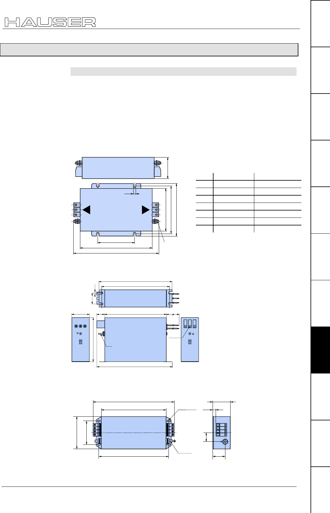
Accessories
EMC measures
191
Unit
hardware
Connector
assignment / cable
Technical dataConfigurationPositioning and
control functions
Optimization
functions
InterfacesAccessories /
options
StatusParameterError list
9.7.4 EMC measures
9.7.4.1 Power filter
The following power filters can be used for RF suppression and compliance with
the emission limit values specified in EN61800-3.
Type: NFI01/02
Type: NFI01/03
Dimension diagram:
6,6
A
B
C
D
E
FG
Ø 4
L
I
N
E
L
O
A
D
Type: NFI01/04
307
61
152
337
320
35 6.5
M5
25 400
347
Line
Netzseite Load
Lastseite
10mm2
COMPAX 35XXM with serially mounted COMPAX-M contr.: Type: NFI01/05
LINE
LOAD
110 ±0.3
150 max.
325 ±1 M10
17Nm
6.5 x 15
301 max.
378 max. 81 max.
15
42
58
Do not loosen the locking nut!
NMD10 / COMPAX
45XXS / 85XXS
COMPAX 1000SL (in
COMPAX 1000SL for
motor lines >50m):
NMD20:
COMPAX 35XXM:
NFI01/02 NFI01/03
A 177 240
B 151 217
C 70±0.3 115±0.3
D 140 159
E 125 145±0.5
F 111 129
G65 64
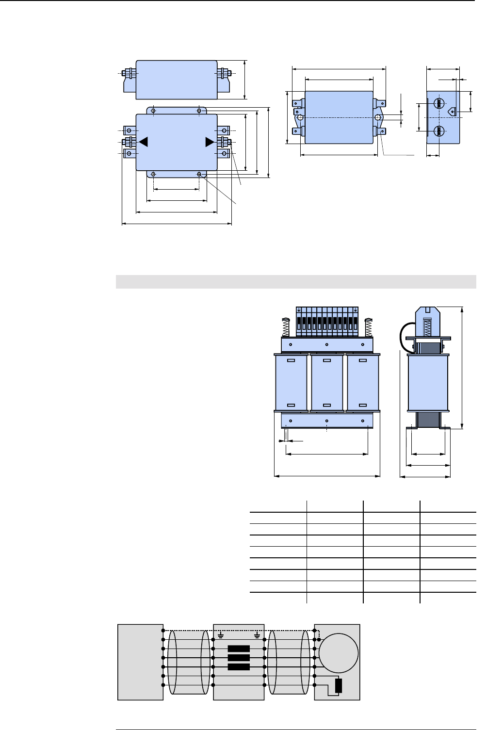
Accessories and options COMPAX-M / -S
EMC measures
192
COMPAX 25XXS: motor cable >10m
COMPAX 10XXSL: motor cable >50m COMPAX 25XXS: motor cable ≤
≤≤
≤10m
Type: NFI01/01 dimension diagr.: Type: NFI01/06 dimension diagram:
50.8±0.3
85.4
116
139
79.5
101
88.9±0.4
55.5
Ø 4
5.2 x 4
L
I
N
E
L
O
A
D
66 max.
91 max.
51 max.
75 ±0.3
5.3
L
N
FASTON
6.3 x 0.8
L'
N'
LINE
LOAD
27
12
32 max.
3.5
20
• Unscreened: <0.5m
♦
Screened: <5m
9.7.4.2 Motor output throttle
We supply motor output throttles for use with long motor lines (greater than 20m)
♦
Type: MDR01/01 16A / 2mH
♦
Type: MDR01/02 30A / 1.1mH
♦
Type: MDR01/03 >30A / 0.64mH
M
motor
PE
PE
U
V
W
Br+
Br-
+
+
--
U1 U2
V2
V1
W1 W2
motor output filterdevice
COMPAX 25XXS:
COMPAX 10XXSL
Length of
connection between
power filter and
unit:
Up to 16A
nominal motor
current:
Up to 30A
nominal motor
current:
Over 30A nominal
motor current:
Wiring of motor
output throttle
MDR01/01 MDR01/02 MDR01/03
A [mm] 150 180 205
B [mm] 67 76 107
D [mm] 113 136 157
E [mm] 50 57 83
F [mm] 6 6 7
H [mm] 195 195 260
I [mm] 95 110 150
Weight [kg] 4 6 17
AB
I
F
DE
H
U1 V1 W1 + - U2 V2 W2 + -
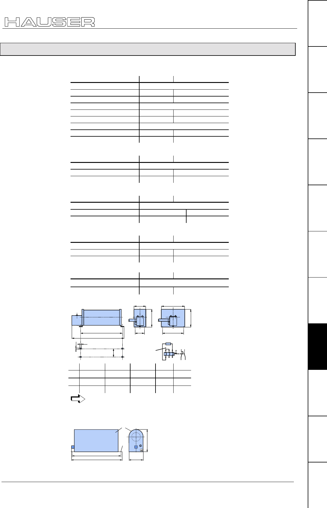
Accessories
External ballast resistors
193
Unit
hardware
Connector
assignment / cable
Technical dataConfigurationPositioning and
control functions
Optimization
functions
InterfacesAccessories /
options
StatusParameterError list
9.7.5 External ballast resistors
NMD20 with external ballast resistance of 15Ω
ΩΩ
Ω
Braking power Duration Cooling down time
BRM4/01: 0.57 kW unlimited
6.8 kW <1s >20s
37 kW <0.4s >120s
BRM4/02: 0.74 kW unlimited
8.9 kW 1s >20s
37 kW <0.4s >120s
BRM4/03: 1.50 kW unlimited
18 kW <1s >20s
37 kW <0.4s >120s
COMPAX 25XXS with external ballast resistance of 56Ω
ΩΩ
Ω
Braking power Duration Cooling down time
BRM5/01: 180W unlimited
1 kW <1s >10s
2.3 kW <0.4s ≥8s
COMPAX 45XXS/85XXS with external ballast resistance of 22Ω
ΩΩ
Ω
Braking power Duration Cooling down time
BRM6/01: 450W
unlimited
6.9 kW
<1s
>20s
28 kW
<0.4s
≥120s
COMPAX 35XXM with external ballast resistance of 10Ω
ΩΩ
Ω
Braking power Duration Cooling down time
BRM7/01: 2.00 kW unlimited
56 kW <1s >100s
17 kW <1s >10s
COMPAX 10XXSL with external ballast resistance of 100Ω
ΩΩ
Ω
Braking power Duration Cooling down time
BRM8/01: 60W unlimited
Dynamic 253W <1s ≥10s
Overloading
protection
switch
95 97
96 98
A
BC
120
6.5
C
92
12
C
120
150
BRM4/01 BRM4/02 BRM4/03 BRM6 BRM7
A 250 300 540 250 560
B 330 380 620 330 640
C 64 64 64 64 150
The ballast resistors are fitted with a 1.5m connecting cable. The maximum
permitted length is 2m.
protection against
contact
∅
∅∅
∅5,8
222
239 71
101
BRM5/01 is fitted with a 0.3m connecting cable.
The maximum permitted length is 2m.
External ballast
resistors:
Dimension diagram:
BRM4, BRM6 and
BRM7
Dimension diagram:
BRM5/01
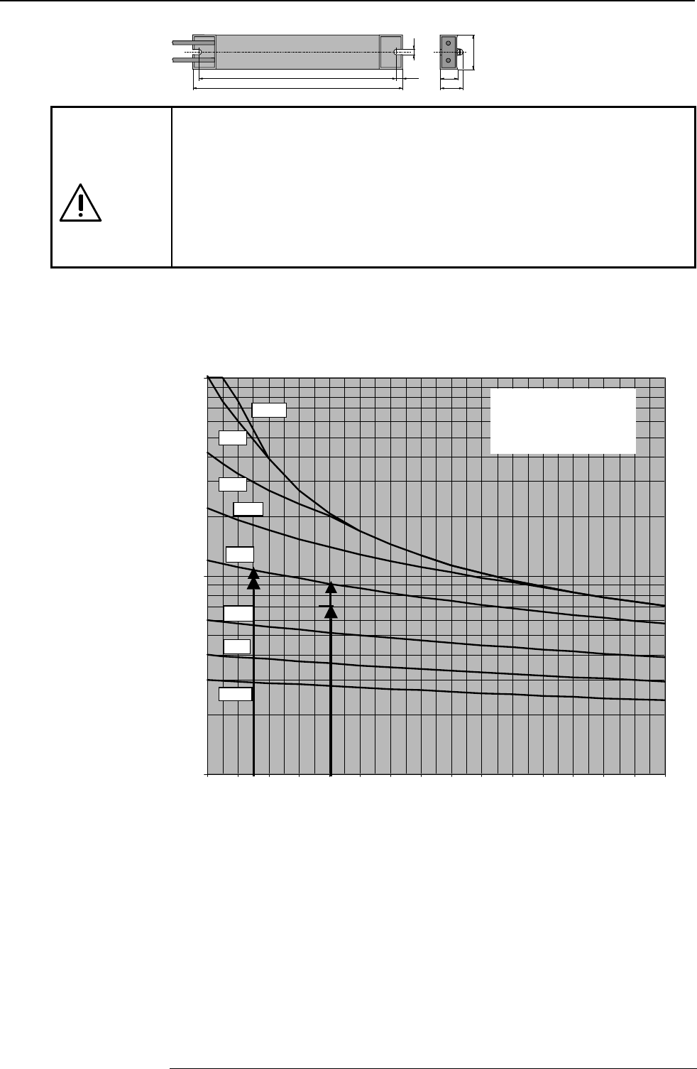
Accessories and options COMPAX-M / -S
External ballast resistors
194
6
7,5
40
20
26
240
225
BRM8/01 is fitted with a 0.25m
connecting cable.
The maximum permitted length
is 2m.
Danger!
Housing temperature may reach 200°C.
Dangerous voltage!
The device may only be used if completely fitted!
The external ballast resistances should be fitted so that contact protection is
provided.
The housing temperature of the ballast resistance may rise to 200°C depending
on the application.
Fit the connection lines underneath.
Observe the information on the resistances (warning signs).
Diagrams: Brake pulse power - cooling period
Authorised braking impulse power with NMD20
100
1000
1
0000
0,0 0,2 0,4 0,6 0,8 1,0 1,2 1,4 1,6 1,8 2,0 2,2 2,4 2,6 2,8 3,0
Braking time / s
Pbdyn / W
F=50
F=5
F=10
F=2
F=1
F=0.5
F=100
F=20
For a braking time of 0.8s, a braking power of 700W is required.
The following can be determined from the diagram:
At the required magnitudes, this is between factor F=2 and factor F=5.
To maintain operating safety, select factor F=5; therefore the required cooling
down time equals:
Cooling down time = F * braking time = 5 * 0.8s = 4s
For a braking time of 0.3s, a braking power of 1000W is required.
The following can be determined from the diagram:
At the required magnitudes, this is between factor F=2 and factor F=5.
To maintain operating safety, select factor F=5; therefore the required cooling
down time equals:
Cooling down time = F * braking time = 5 * 0.3s = 1.5s
Dimension diagram:
BRM8/01
Example 1:
Example 2:
700W
F: Factor
Cooling down time = F *
braking time
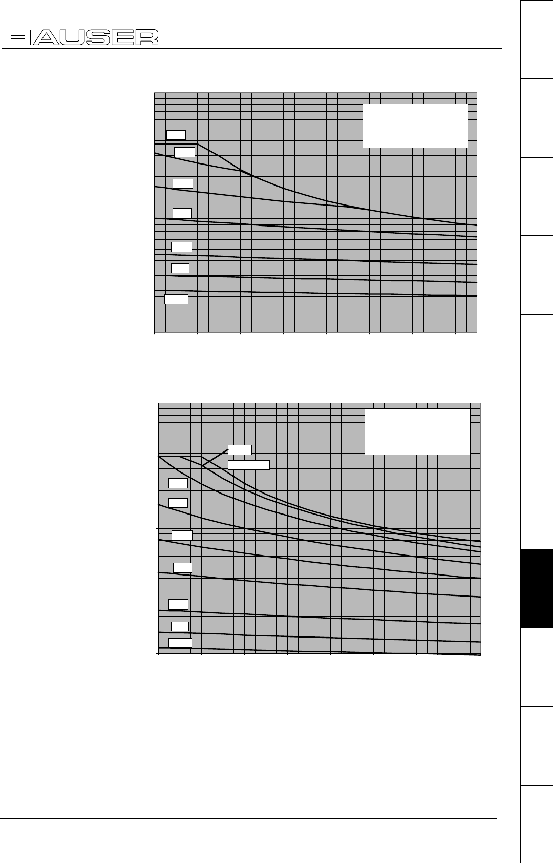
Accessories
External ballast resistors
195
Unit
hardware
Connector
assignment / cable
Technical dataConfigurationPositioning and
control functions
Optimization
functions
InterfacesAccessories /
options
StatusParameterError list
Authorised braking impulse power for NMD20 with BRM4/03
1000
10000
100000
0,0 0,2 0,4 0,6 0,8 1,0 1,2 1,4 1,6 1,8 2,0 2,2 2,4 2,6 2,8 3,0
Braking time / s
Pbdyn / W
F=50
F=5
F=10
F=2
F=1
F=0.5
F=20
Authorised braking impulse power for NMD20 with BRM4/02
1000
10000
100000
0,00,20,40,60,81,01,21,41,61,82,02,22,42,62,83,0
Braking time / s
Pbdyn / W
F=50
F=5
F=10
F=2
F=1
F=0.5
F=100
single pulse
F=20
F: Factor
Cooling down time = F *
braking time
F: Factor
Cooling down time = F *
braking time
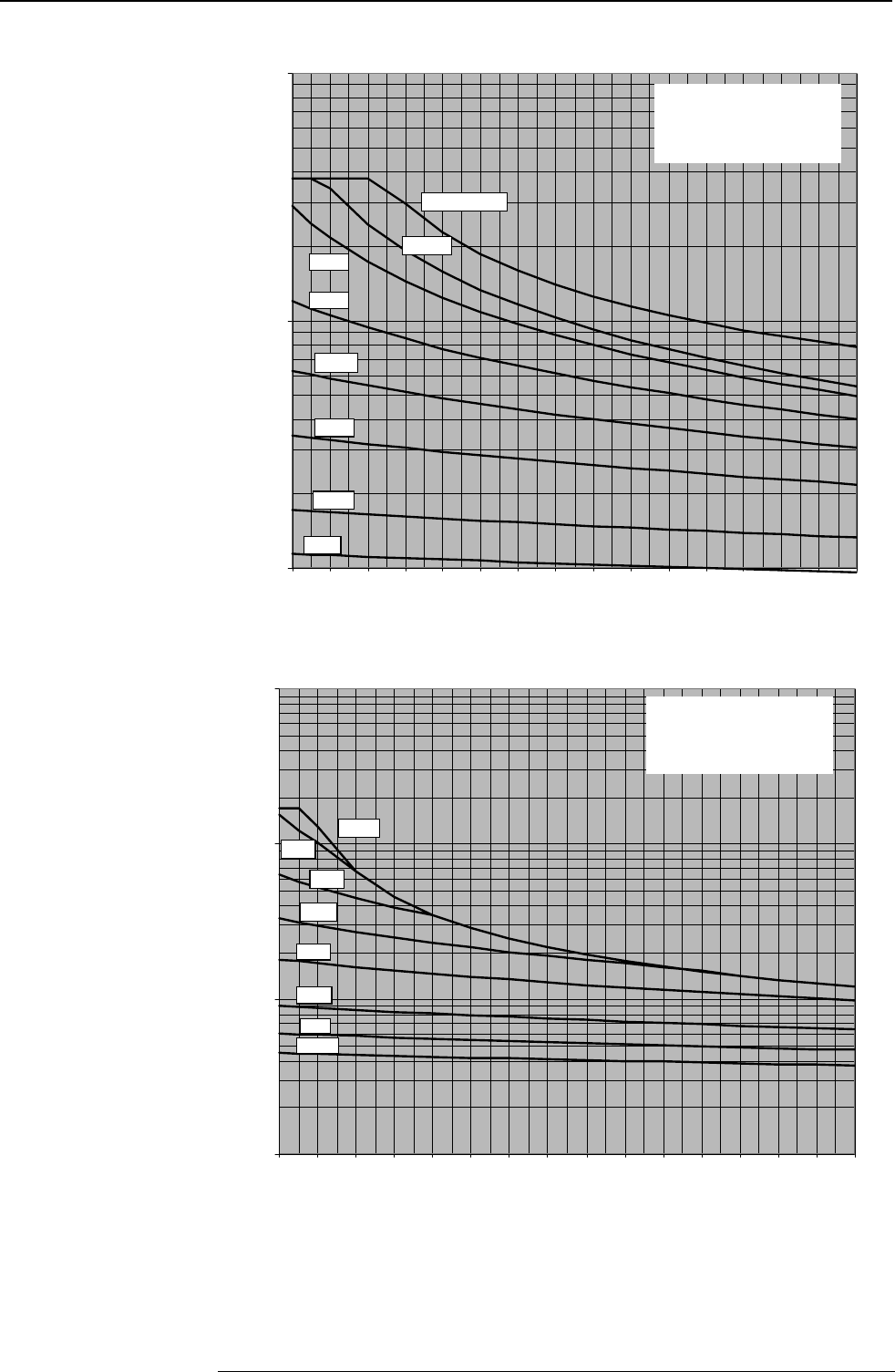
Accessories and options COMPAX-M / -S
External ballast resistors
196
Authorised braking impulse power for NMD20 with BRM4/01
1000
10000
100000
0,0 0,2 0,4 0,6 0,8 1,0 1,2 1,4 1,6 1,8 2,0 2,2 2,4 2,6 2,8 3,0
Braking time / s
Pbdyn / W
F=50
F=5
F=10
F=2
F=1
F=100
single pulse
F=20
Authorised braking impulse power for NMD10
100
1000
10000
100000
0,00,20,40,60,81,01,21,41,61,82,02,22,42,62,83,0
Braking time / s
Pbdyn / W
F=50
F=5
F=10
F=2
F=1
F=0.5
F=100
F=20
F: Factor
Cooling down time = F *
braking time
F: Factor
Cooling down time = F *
braking time
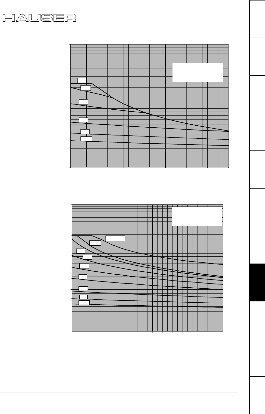
Accessories
External ballast resistors
197
Unit
hardware
Connector
assignment / cable
Technical dataConfigurationPositioning and
control functions
Optimization
functions
InterfacesAccessories /
options
StatusParameterError list
Authorized braking impulse power for COMPAX 2500S with BRM5/01
100
1000
10000
0,00,20,40,60,81,01,21,41,61,82,02,22,42,62,83,0
Braking time / s
Pbdyn / W
F=50
F=5
F=10
F=2
F=1
F=0.5
Authorised braking impulse power for COMPAX 4500S and
COMPAX 8500S
100
1000
10000
100000
0,0 0,2 0,4 0,6 0,8 1,0 1,2 1,4 1,6 1,8 2,0 2,2 2,4 2,6 2,8 3,0
Braking time / s
Pbdyn / W
F=50
F=5
F=10
F=2
F=1
F=0.5
F=100
single pulse
F=20
F: Factor
Cooling down time = F *
braking time
F: Factor
Cooling down time = F *
brakin
g
time
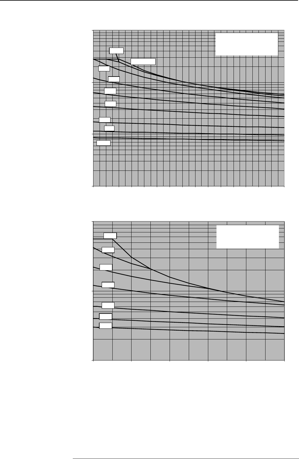
Accessories and options COMPAX-M / -S
External ballast resistors
198
Authorised braking impulse power for COMPAX 4500S and
COMPAX 8500S with BRM 6/01
100
1000
10000
100000
0,0 0,2 0,4 0,6 0,8 1,0 1,2 1,4 1,6 1,8 2,0 2,2 2,4 2,6 2,8 3,0
Braking time / s
Pbdyn / W
F=50
F=5
F=10
F=2
F=1
F=0.5
F=100
single pulse
F=20
Authorised braking impulse power for COMPAX3500M with BRM7/01
1000
10000
100000
0,0 2,0 4,0 6,0 8,0 10,0
Braking time / s
Pbdyn / W
F=50
F=5
F=10
F=2
F=1
F=0.5
F=20
F: Factor
Cooling down time = F *
braking time
F: Factor
Cooling down time = F *
braking time
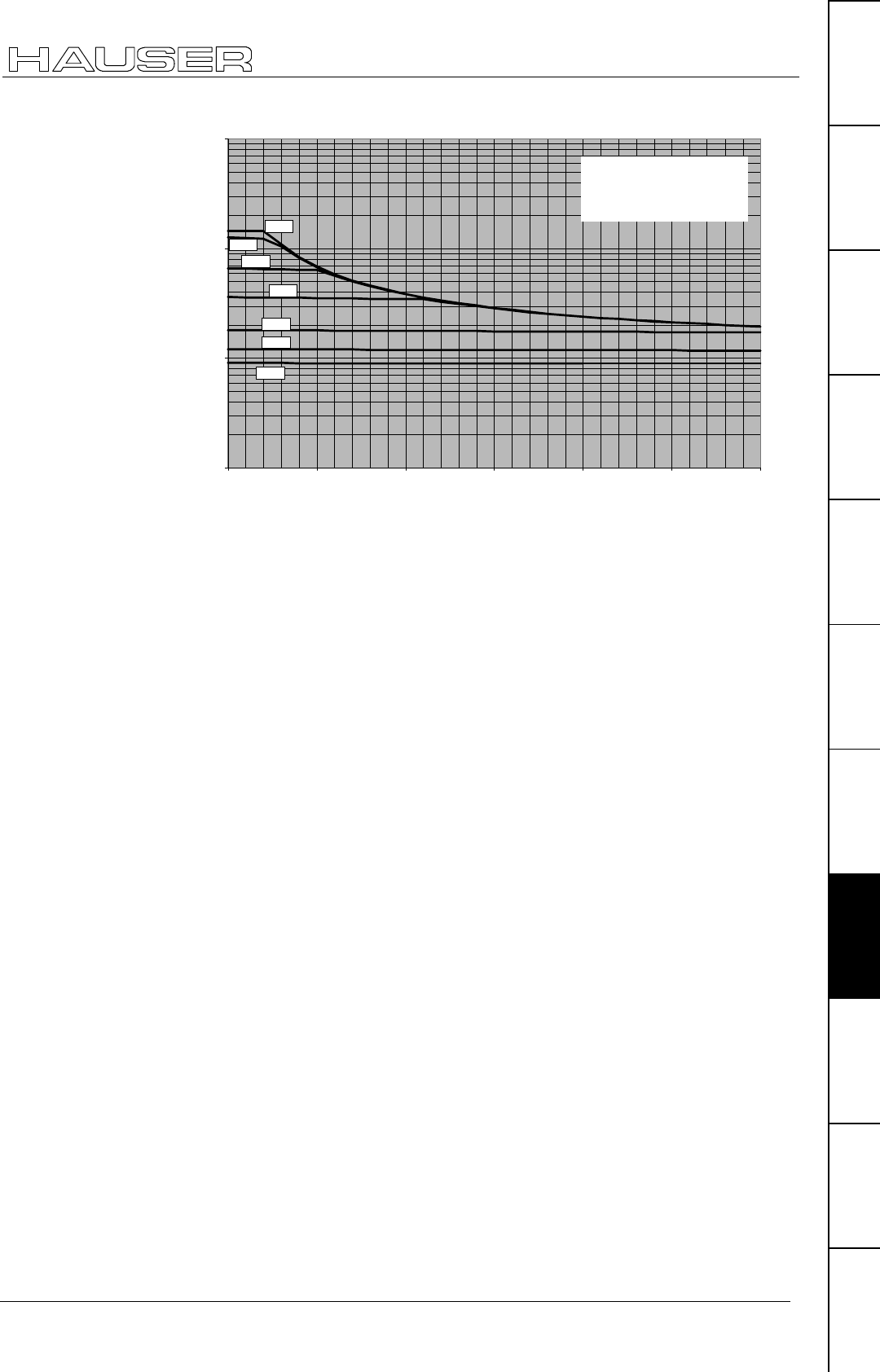
Accessories
External ballast resistors
199
Unit
hardware
Connector
assignment / cable
Technical dataConfigurationPositioning and
control functions
Optimization
functions
InterfacesAccessories /
options
StatusParameterError list
Permissible brake pulse power for COMPAX 1000SL with BRM8/01
10
100
1000
10000
0.0 0.5 1.0 1.5 2.0 2.5 3.0
Braking Time [s]
PBdyn [W]
F=50
F=20
F=10
F=5
F=2
F=1
F=0,5
F: Factor
Cooling down time = F *
braking time
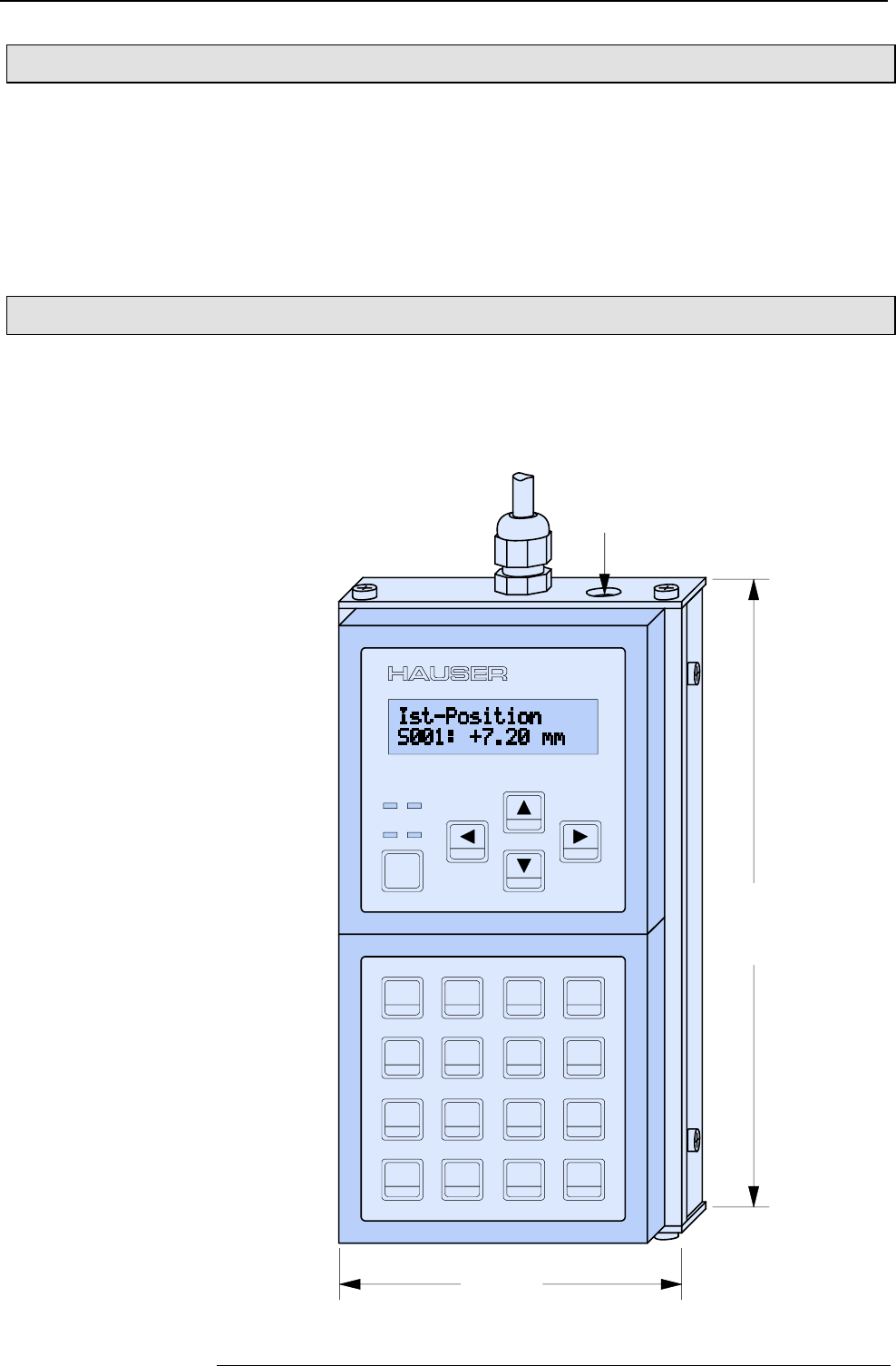
Accessories and options COMPAX-M / -S
ServoManager
200
9.7.6 ServoManager
Use the ServoManager to process complete COMPAX projects; it is included with
COMPAX. It contains the following program modules:
♦
ParameterEditor: for configuring and parametrizing COMPAX.
♦
ProgramEditor: for creating COMPAX programs
♦
Terminal: for working directly on the connected COMPAX.
The ServoManager and the program modules are described in a separate manual.
9.7.7 Hand-held terminal
The BDF2/01 hand-held terminal is a simple aid with which you can operate and
easily configure COMPAX with the guided menus. The hand-held unit is connected
to COMPAX X6 and powered via the RS232 interface. It is therefore suitable for
rapid diagnosis and supporting start-up.
100mm
180mm
COMPAX
789
456
123
+/- 0 .
NO
YES
Esc
Ent
DELETE
SHIFT
P
N
INSERT
H1 H2
SHOK
REPEAT IF OUTPUT F1
F2RETURNGOSUBGOTO
POSA SPEED ACCEL F3
F4ENDWAITPOSR
depth:
45mm
5V-plug for
RS232-cable >5m.
HB-plug 1,95/5,5mm
control knob 6mm
polarity: + outside
Design:
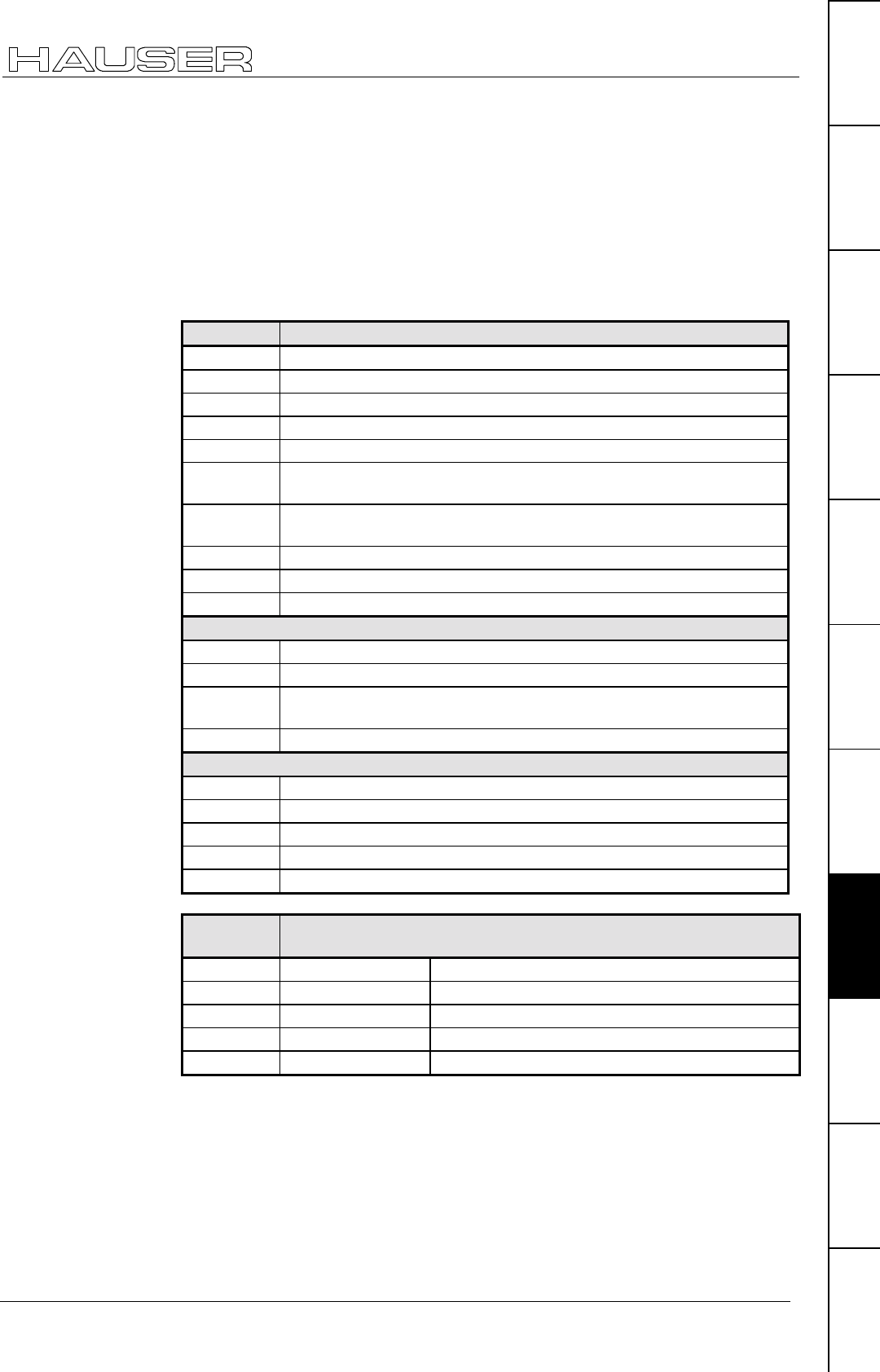
Accessories
Hand-held terminal
201
Unit
hardware
Connector
assignment / cable
Technical dataConfigurationPositioning and
control functions
Optimization
functions
InterfacesAccessories /
options
StatusParameterError list
The hand-held terminal contains the following functions:
♦
display any status value.
♦
menu-guided configuration
♦
view and edit programs.
♦
view and edit parameters
♦
direct entry of commands
The keys are all assigned two functions. Press the SHIFT key to activate the
second function of a key. The second function is displayed in turquoise in the lower
section of the key.
Keys Function
NO Answers a question negatively
YES Answers a question positively
ESC Escape
ENT Confirms and accepts
SHIFT Selects second function of the key: press once: on; press again: off
DELETE Deletes program data record, all jumps to addresses are
automatically corrected
INSERT Inserts program data record, all jumps to addresses are
automatically corrected
P Directly select parameter input
N Directly select program memory
F3 Quit
Special functions
WAIT Ent WAIT START
GOTO Ent GOTO EXT
GOSUB
Ent
GOSUB EXT
SPEED Ent SPEED SYNC
Special COMPAX XX70 commands
F1 SETC x
F2 SETM x
F3 SETS
F4 LOOP x
POSR Ent POSR CAM
Lit display Function
dark bright
H1 (red) No error Error
H2 (amber) No warning Warning: heat sink temperature >70°C
OK (green) Unit not ready Unit ready for operation
SH (amber) First key function Second key function (SHIFT key pressed)
All No voltage Unit not ready for operation
The cable is 1.5 m long. The hand-held terminal is also powered through this cable.
If the distances involved are longer (>5m), the hand-held terminal will require a
direct power supply for fault-free operation.
When an error message is present, you can modify the parameter and
configuration. To do this, press ESC; the error display goes out and the menu
appears. The H1 LED indicates that the error is still present. Once you have
modified the parameter, acknowledge the error using F3.
Functions
Key functions
Supply
Error handling
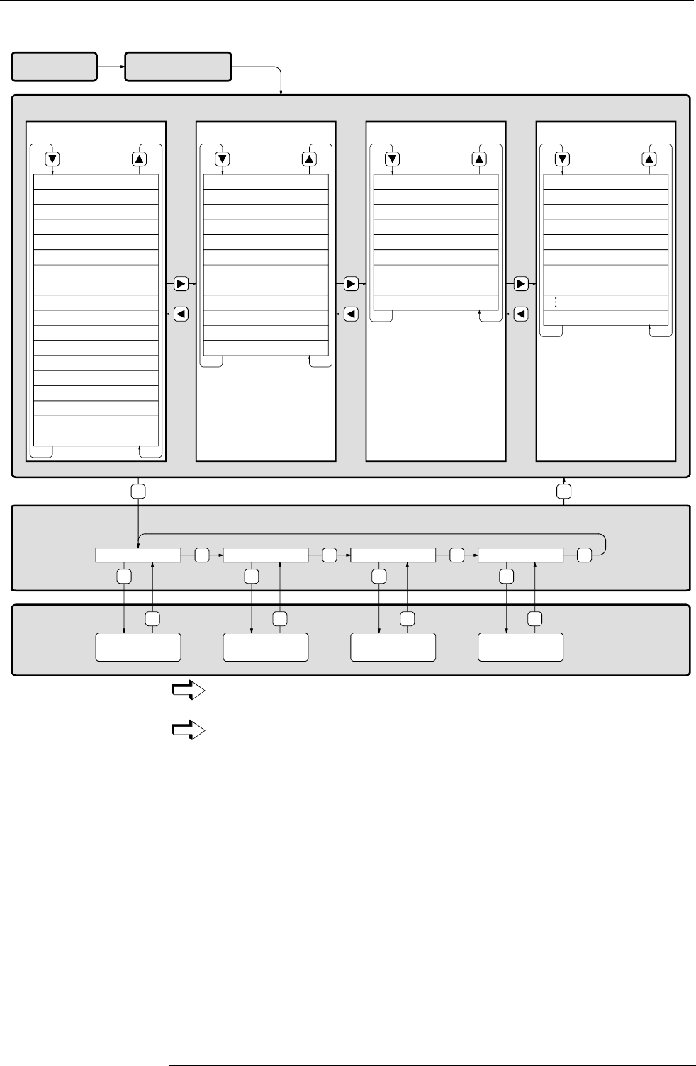
Accessories and options COMPAX-M / -S
Hand-held terminal
202
Menu:
Status Level
Function Level
Setting Level
see, edit, delete
program Enter commands see, set up
configuration
see, edit, delete
parameters
Set Up Mode ?Parameter Mode ?Command Mode ?Program Mode?
Esc
YES
Esc
NO
YES
Esc
NO
YES
Esc
NO
YES
Esc
NO
Esc
BDF2/01 Version
Date
COMPAX Typ Version
P20= value
Actual Values
Actual Position
Target Position
Tracking Error
Speed
Torque
Temperature
Control Voltage
Power Voltage
Position Cycles
Operationg Hours
Repeat Counter
Encoder Position
optimization dispaly P233
optimization display P234
status-monitor P182
standard config. A1-A6
enlarged status info.
error history
Diagnosis Values
I1 - I8
I9 - I16
O1 - O8
O9 - O16
Status Motor
Status Switches
Status Limits
Status Output stage
Current Command
RS232 Data
Bus Data
Last Error
Identification
Software Version
Release Date
Commission
Part
Version
Language
Power Stage
Special Status Value
S40: number
S41
S42
S43
S44
S45
S46
S47Device Family
Device no.
When the hand-held terminal is connected to COMPAX, the password
remains the same.
The menu items of the setting levels are described below.
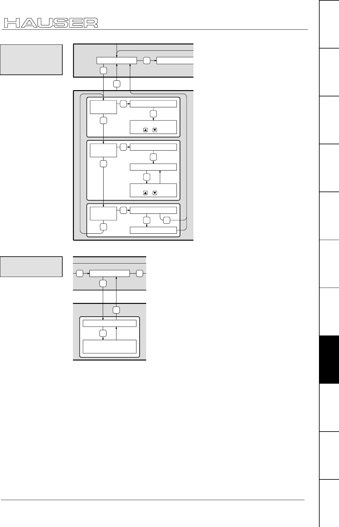
Accessories
Hand-held terminal
203
Unit
hardware
Connector
assignment / cable
Technical dataConfigurationPositioning and
control functions
Optimization
functions
InterfacesAccessories /
options
StatusParameterError list
View
Program ?
Edit
Program?
NO
NO
YES
NO
Enter block no.
Ent
Select other blocks
using or .
YES Enter block no.
Ent
Select other blocks
using or .
Edit block
Ent
YES Are You sure
Program is deleted
NOYES
YES
Program Mode ?
Delete
Program?
Esc
NO Command Mode?
Commands or numerical values are modified by overwriting them.
YES
Esc
NO
Command Mode ?
NO
Enter command
Ent
Command is transferred
by COMPAX
Once you have transmitted the command using "Ent", this command reappears in
the display and it can be modified and transmitted again.
When OUTPUT O.="X", the cursor is positioned under "X" after the command is
transmitted. The value can be modified and transmitted.
View,
edit, delete
program
Direct
command entry
Special control
function
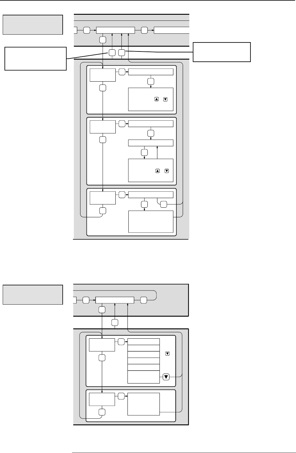
Accessories and options COMPAX-M / -S
Hand-held terminal
204
View
Parameters?
Edit
parameters?
NO
NO
YES
NO
Enter Parameter no.
Ent
Select other para-
meters using or or
edit parameter no.
YES Enter Parameter no.
Ent
Select other para-
meters using or
edit parameter no.
Edit Parameter no.
Ent
YES Are You sure ?
Parameters are set
to defaults;
reconfigure the device
NOYES
YES
Parameter Mode ?
Reset
Parameters?
Esc
NO Set up Mode ?
NO
No
♦
When you exit the "Parameter edit" menu using "Esc", the "VC" command
(transfer configuration) is transmitted to COMPAX. The configuration
parameters are therefore only valid from this moment.
♦
When exiting the "Parameter edit" menu using "NO", the "VC" command is not
transmitted.
Con-
tinue
with
YES
Esc
NO
Set Up Mode ?
NO
YES Operating Mode
Measurement unit
Ramp shape
Drive type
Drive type
Parameter of
Drive type
View
Set up?
NO
YES
Update
Set Up ?
NO
Update Set
Up
(see below)
View, edit and
reset parameter
View, set
configuration
"VC" is generated
when you exit the
menu.
Exits the menu
without "VC".
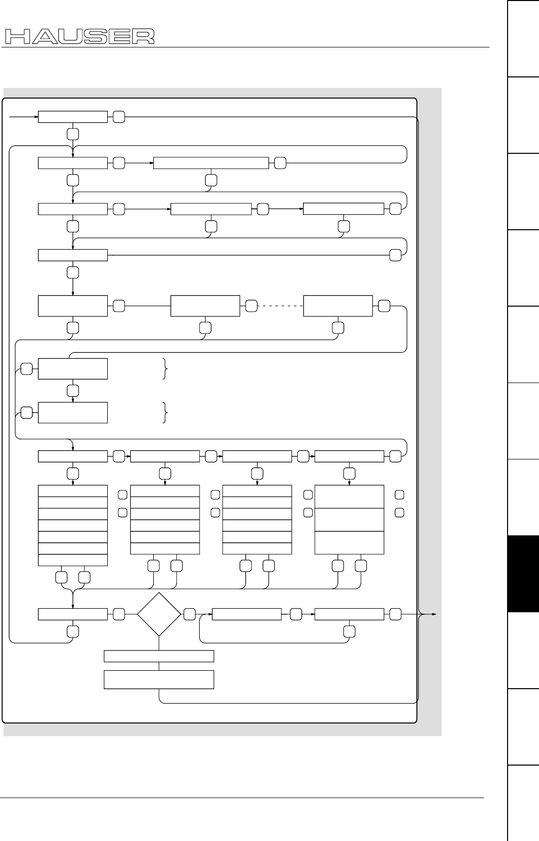
Accessories
Hand-held terminal
205
Unit
hardware
Connector
assignment / cable
Technical dataConfigurationPositioning and
control functions
Optimization
functions
InterfacesAccessories /
options
StatusParameterError list
Set configuration
NO
YES
Mode: Normal ? Mode: Endless ?
NO NO
YES
Input unit: mm ? NO Input unit: inch ? NO
YES
YES
YES
Accel: linear ?
YES
NO NO
Input unit: incr
Spindle Drive ? NO NO NO
Rack and pinion ? Timing belt ? Universal Drive ?
Spindle Length
Spindle Diameter
Spindle Slope
Gear ratio
Inertia gear
Minimal load
Maximal load
Teeth in pinion
Pitch if teeth
Gear ratio
Inertia gear
Minimal load
Maximal load
Teeth in pinion
Pitch in teeth
Gear ratio
Inertia gear
Minimal load
Maximal load
Inertia minimum
Inertia maximum
Travel path per
motor revolution
YES YES YES YES
Switch off Motor ?
YES Ent
YES Ent YES Ent YES Ent
All correct ?
NO
YES Switch on motor ? Switch off motor ?
YES
NO
Changes values and
YES Ent
continue with or
NO
Ent
NO
YES
Selected motor? NO
P100 = XXX
YES You can configure a motor individually by setting P100=0. Therefore
fill in the motor data and the motor parameters (from P101)
The standart motors (HBMR- and HDS-Motors)
can be configured via the motor number.
YES
NO
Motor type 1
P100 = XXX
YES
NO
Motor type n
P100 = XXX
HDX/Individual motor
P100 = 0
Motor number
P100 = ...
NO
YES
HDX/
Individual
motor
NO YES
enter motor parameter from P100
enable drive by power off/on or by
command output O0=0
Changes values and
YES Ent
continue with or
Changes values and
YES Ent
continue with or
Changes values and
YES Ent
continue with or
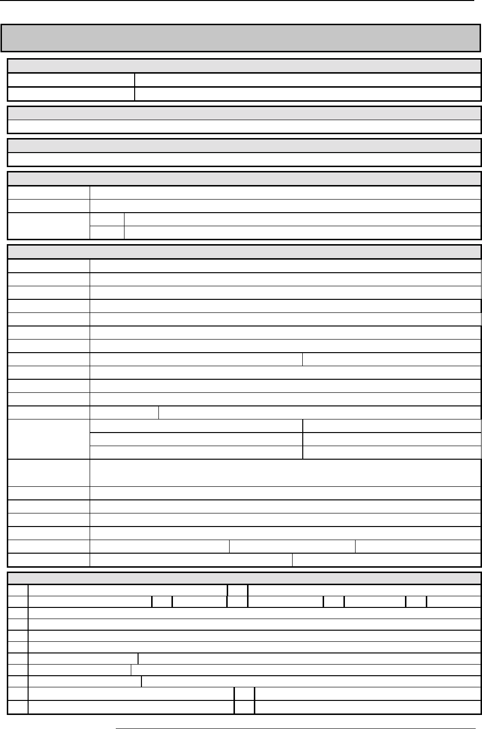
Accessories and options COMPAX-M / -S
Hand-held terminal
206
9.8 Appendix: COMPAX components
Mains module for COMPAX-M (excluding COMPAX 35XXM)
NMD10 Up to 3 x 500 V AC mains supply connection; direct mains supply operation 10 kW cont. output
NMD20 As NMD10, but with 20 kW continuous output; external ballast resistances available in 3 sizes.
HDY and HJ motors
You will find information about our range of motors in the motor documentation.
Motor and resolver cable for HDY and HJ motors
You will find motor and resolver cables on Page 46.
HAUSER linear unit and initiator equipment
HLE 80mm / 100mm / 150mm edge length (ask for information material!)
HPLA 80mm / 120mm / 180mm edge length (ask for information material!)
Initiator equipment IVD1/. Initiator distr.connect. w. cables of the f. lengths [m]:2.5; 5; 7.5; 10; 12.5; 15; 20; 25; 30; 35; 40; 45; 50
Initiator PNP induction proximity switch: IN HE 521 506 with 6m cable.
Accessories
BDF2/01 Hand-held terminal for configuring and operating COMPAX
BDF1/03 External control panel with housing and without cable
BDF1/02 External control panel for front plate installation without cable
SSK6/.. Interface cable between contr. panel and COMPAX av.- in the following lengths: 2.5; 5; 7.5; 10; 12.5; in [m]
SSU1/01 RS232 - RS485 converters used in conjunction with option F1
GBK16 COMPAX – motor cable for disposing of SinCos.
Encoder: GBK11/.. Encoder cable for connecting COMPAX with an encoder.
EAM4/01 Encoder distributor for creating an encoder bus. BUS1/01 Bus termination for encoder bus
SSK4/.. Connector cable between COMPAX and encoder distributor.
SSK7/.. Connector cable between encoder distributors or from an encoder emulation.
ASS1/01 Monitor box for outputting internal measurement signals with D1 option.
SSK1/.. RS 232 Interface cable for PC COMPAX, available in the following lengths: 2.5; 5; 7.5; 10; in [m]
Ballast resistors NMD20: BRM4: 0.57 kW-1.5 kW (15Ω)COMPAX 25XXS: BRM5/01: 250W (56Ω)
COMPAX 45XXS/85XXS: BRM6/01: 450W (22Ω)COMPAX 35XXM: BRM7/01: 2 kW (10Ω)
COMPAX 1000SL BRM8/01: 60W (100Ω)
AC power filter NMD10 / COMPAX 45XXS/85XXS: NFI01/02 COMPAX 25XXS: NFI01/01 or NFI01/06 (≤ 10m motor cable)
COMPAX 35XXM: NFI01/04 or NFI01/05 (with additional COMPAX-M) NMD20: NFI01/03
COMPAX 1000SL: NFI01/01 (<50m motor cable) or NFI01/02 (>50m motor cable)
Motor outp. throttle For motor lines >20m: MDR01/01 (16A/2mH) • MDR01/02 (30A/1.1mH) • MDR01/03 (>30A/0.64mH)
Ass. angle bracket: MTS2: for indirect wall installation (heat sink in separate heat chamber) of COMPAX 02/05/15XXM
Fan set for NMD Fan set for NMD10 and NMD20 to increase max. brake performance
ServoManager To read and write COMPAX parameters and programs
Bus terminal BUS1/01: Encoder bus BUS2/01: HEDA BUS3/01: Profibus
BUS4/01: RS485 BUS6/01: Encoder terminal for COMPAX 1000SL
Options
F1 4-wire RS485 interface F5 2-wire RS485 interface
F2 Interbus S interface F3 Profibus F7 CS31 F8 CANopen F4 CANbus
E2 Encoder interface with line terminator for individual connections.
E3 Encoder simulation for resolver
E4 Encoder interface without line terminator for creating an encoder bus.
E7 Analogue speed specification only for COMPAX XX6X and COMPAX XX70 or for SPEED SYNC with COMPAX XX00!
A1 Absolute value sensor/HEDA Cable to COMPAX: GBK1/.. lengths: 2.5; 5; 7.5; 10; 12.5; 15; 20; 25; 30; 35; 40; 45; 50 [m]
A4 HEDA f. COMPAX 1000SL Cable COMPAX/COMPAX: SSK14/.. lengths :2.5; 5; 7.5; 10; 12.5; 15; 20; 25; 30; 35; 40; 45; 50 [m]
D1 D/A monitor To output the measurement signals, you will need monitor box ASS1/01.
S1 Sensor interface for SinCos, single-turn or multi-turn S2 Programmable sensor interface for SinCos multi-turn
S3 Sensor–interface for linear motors (cable: GBK18)
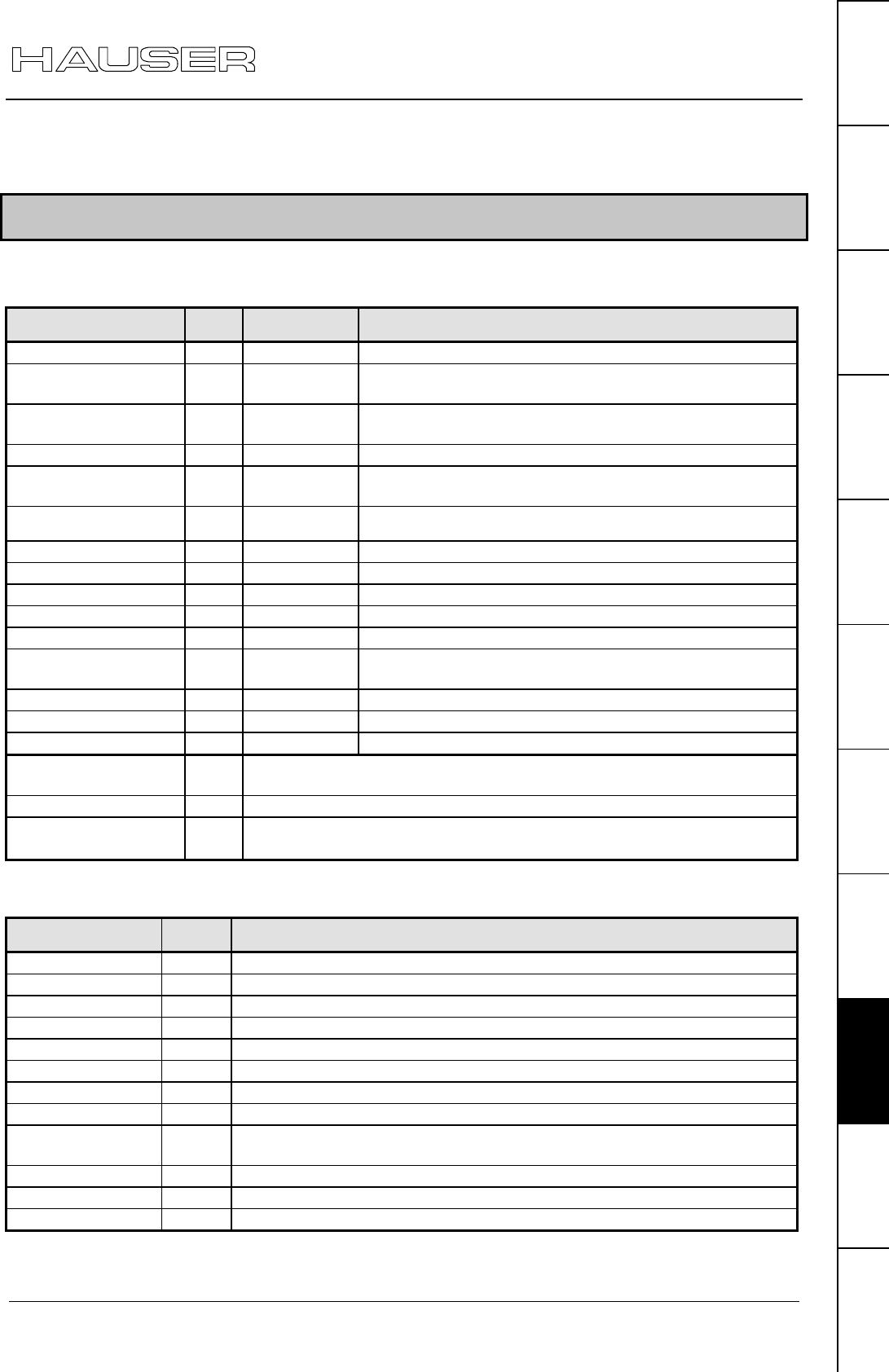
Status values of the standard unit (COMPAX
XX00)
207
Unit
hardware
Connector
assignment / cable
Technical dataConfigurationPositioning and
control functions
Optimization
functions
InterfacesAccessories /
options
StatusParameterError list
10. Appendix
10.1 Status values of the standard unit (COMPAX XX00)
Actual values
Designation: Status
No. Unit Meaning
Actual position S01 corresp. P90 Current position referenced to real zero.
Target position S02 corresp. P90 End position of current or last positioning cycle
implemented.
Lag error S03 0.1
[corresp. P90]
Difference between nominal and actual position during a
positioning cycle.
Velocity S04 [%] Current axis traversing speed.
Torque S05 [%] Current torque as a percentage of the nominal motor
torque.
Temperature S06 [°C]
C is transmitted Temperature of power final stage (≤ 85°C)
Control voltage S07 [V] Value of control voltage
Mains power S08 [V] Value of power or intermediate circuit voltage
Travel cycle S09 - Number of axis motion cycles.
Operating hours S10 [h] COMPAX controller operating hours
Repeat counter S11 - Loop counter of an active REPEAT loop.
Sensor position S12 corresp. P90 Position of absolute value sensor (option A1) not available
in COMPAX XX10 and COMPAX XX30.
Optimization display S13 With optimization parameter selected using P233.
Optimization display S14 With optimization parameter selected using P234.
Status monitor S15 D/A monitor value selected using P182.
Status bits 1 S16 Information from the status outputs O1...O6 and the last OUTPUT O0
command
Status bits 2 S17 Information about COMPAX status.
Error history S18 The last 4 errors and type of acknowledgement. See below.
(all errors but E00, E47, E72 and >E90)
Diagnosis values
Designation: Status
No. Meaning
I1-I8 S19 Logic signal level of inputs 1...8
I9-I16 S20 Logic signal level of inputs 9...16
O1-O8 S21 Logic signal level of outputs 1...8
O9-O16 S22 Logic signal level of outputs 9...16
Status drive S23 Diagnosis values for the status of the drive. (see below for meaning)
Status switch S24 Diagnosis values for the status of the switch. (see below for meaning)
Status limits S25 Diagnosis values for the limit value monitoring . (see below for meaning)
Status final stage S26 Diagnosis value for the status of the final stage.
Current data
record S27 Display of the data record currently being executed.
RS232 data S28 reserved
Bus data S29 Interbus-S data / PLC data interface / RS485
Last error S30 Error number of the last error to occur (all errors but E00, E72 and >E90).
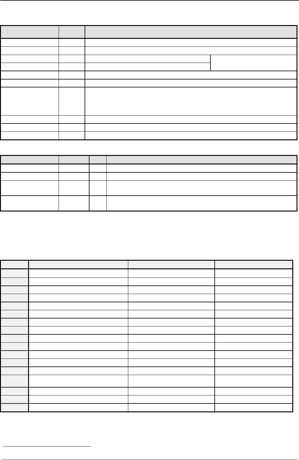
Appendix COMPAX-M/S
Hand-held terminal
208
Unit designations
Designation: Status
No. Meaning
Software version S31 Designation of software version.
Software date S32 Date when program was created.
Order S33 Order number (6 digits) Order&part (10 digits) is
Part S34 Serial four-digit number a unique unit no.
Version S35 Not assigned.
IFM identification S36 Date, version and designation of the bus option (hardware module)
Unit designation S37 COMPAX P1XXM: 80 COMPAX P1XXM N1: 90 COMPAX 02XXM: 85
COMPAX 05XXM: 170 COMPAX 15XXM: 500 COMPAX 35XXM: 1000
COMPAX 25XXS: 4 COMPAX 45XXS: 6 COMPAX 85XXS: 5
COMPAX 10XXSL: 20
Unit family S38 E.g. "00": COMPAX XX00 "30": COMPAX XX30 ...
Unit S39 "0": COMPAX E "1": COMPAX-M "2": COMPAX-S "4": COMPAX-SL "9": SV drive
Status values S40 Number of status values present
Special COMPAX XX00 status values
Designation: Status No. Unit Meaning
Speed S41 % External velocity when using the SPEED SYNC command.
Encoder position S42 P90 External position when using external position localization.
Measuring error S47 P90 During external position localization: difference between resolver
position and encoder position.
Current nominal
value S49 P90 Current internal nominal value (output of nominal value setter and
track nominal value directly specified by HEDA).
Meaning of status bits
The status bits are not relevant for normal operation; they must not be used for control purposes. They do
provide accurate error analysis if you contact HAUSER in case of problems. - The bits are counted from the
left to the right.
S23, S24, S25
Bit Drive status (S23) Switch status (S24) Limits status (S25)
-1111------1111--111--111--11042-- -11--11--11--11-
1 (left) Not assigned Not assigned Not assigned
2Drive not at standstill Override function reserved
3Deceleration phase Limit switch 2 (-) activated reserved
4Acceleration phase Limit switch 1 (+) activated Not assigned
5Speed reached (speed regulation) Not assigned Not assigned
6Not assigned Not assigned No motor current
7Not assigned Zero initiator activated
8Not assigned reserved Not assigned
9Not assigned reserved Not assigned
10 Not assigned Not assigned Position not OK.
11 Not assigned Not assigned Tracking error
12 Speed reached (positioning) reserved Not assigned
13 Positioning process complete Do not change data record
(emergency stop) Not assigned
14 Drive blocked reserved Speed limit reached
15 Machine zero reference present Not assigned Current limit reached
16 (right) Not assigned Not assigned Not assigned
42 The "0" is not shown on the front plate.
Status values of the standard unit (COMPAX
XX00)
209
Unit
hardware
Connector
assignment / cable
Technical dataConfigurationPositioning and
control functions
Optimization
functions
InterfacesAccessories /
options
StatusParameterError list
Output of status bits via the front plate
The status bits are output via the front plate using 2 hex values.
S16, S17
S16:
Bit Meaning
1 ="1":No fault
="0":errors E1 ... E57; the drive does not accept any positioning commands.
After "Power on", bit 1 remains at "0" until the self-test has been executed.
2 ="1":No warning
="0" Error ≥ E57
3 Machine zero has been approached
4 Ready for start
5 Programmed nominal position reached
6 Idle after stop
7, 8 Bit 7 Bit 8
0 0 after OUTPUT O0 = "0"
1 0 after OUTPUT O0 = "1"
0 1 after OUTPUT O0 = "2"
S17:
Bit Meaning when "1"
1 Password 302 active
2 Service password active
3Command active; move commands (POSA, POSR; speed in speed control mode) are rejected using
E92.
4 Program memory running
5 Stop via input I6
6 reserved
7 RUN ("0" = OFF or switched off when error occurs)
8 ---
Bit sequence during transmission of S16 / S17:
Bit 1 is on the left (the transmission starts with bit 1)
E.g.: S17= "1000 0000" during ASCII transfer.
COMPAX front plate: display "01"
E.g.: password 302 active S17 = 0x80 (if all other bits ="0").
Explanation of error history S18
The errors which occur are recorded by COMPAX in an 8-stage shift register. The entire contents of this
memory can be read using a status query. Once the error has been acknowledged, "99" is inserted. Once a
new error occurs, this is inserted in the shift memory.
When querying using S18, the contents of the shift register are output separated by spaces.
Once the unit is switched off, S18 is retained. If the unit is switched off while an error is present, a Power On
acknowledgement is created when the unit is switched on, i.e. a "98" is inserted in the shift memory.
Example: S18CRLF
Response: S018: 99 55 10 99 53 98 10 99CRLR>
♦
The last error, an emergency stop (E55), has been acknowledged.
♦
E10 occurred before this (E10 has not been acknowledged).
♦
E53 has been acknowledged.
♦
E10 has been acknowledged by Power on.
The error memory is completely reset to "00" by the reset parameter, i.e. "00" means no errors.
Bit 1
Appendix COMPAX-M/S
Hand-held terminal
210
Status monitor S15
You can assign the values of the service D/A monitor to status S15 using parameter P182.
Selection of status value using P182
P182 Measuring parameter Reference
parameter
0 Nominal speed value sensor 20 000 min-1
1 Tracking error 128 motor
revolutions
2 Advance speed control 20 000 min-1
3 Nominal speed value of position controller 20 000 min-1
4 Actual speed value 20 000 min-1
5 Loop difference for speed 20 000 min-1
6 Not assigned
7 Not assigned
8 Nominal value of transverse current (torque)43 200A
9 Intermediate circuit voltage 1000V
10 Sine for co-ordinate transformation
11 Voltage positioning signal for phase U
12 Voltage positioning signal for phase V
13 Phase current for phase U 200A
14 Phase current for phase V 200A
15 Actual value of transverse current (torque)44 200A
16 Longitudinal current 200A
17 Scaled transverse voltgage (For amplification 1 use: 10V = 2 * ULS ) 2 * ULS
18 Scaled longitudinal voltage (For amplification 1 use: 10V = 2 * ULS ) 2 * ULS
The reference parameter corresponds to value 1.
Note concerning status monitor S15
Scaling status monitor S15:
S15 does not have the same scaling as S13/S14.
For S15 use: S15=1 for the reference value which is given for the D/A monitor.
10.2 Additional COMPAX measuring quantites
D/A monitor channels 0 ... 3
Status monitor S15 (P182); HEDA Signal indicators (optimization display) S13 / S14
(P233/P234)
Selec-
tion Measuring quantity Reference
value Selec
tion Meaning
0 Nominal speed value sensor 20 000 min-1
1 Tracking error 128 motor
revolutions
1 Positioning time (from start of positioning to "Position reached")
2 Advance speed control 20 000 min-
1
2 max. intermediate circuit voltage in [V]
3 Nominal speed value of position controller 20 000 min-
1
3 reserved
4 Actual speed value 20 000 min-
1
4max. undershoot referenced to max. position (amount) (only for highly
misadjusted loops)
5 Loop difference for speed 20 000 min-
1
5 max. position overshoot [units corresp. P90] (amount)
6 Not assigned 6 max. position undershoot [units corresp. P90] (amount)
7 Speed controller output (nominal current value) 200A 7 max. acceleration lag error [units corresp. P90]
8 Nominal value of transverse current (torque) 200A 8 max. braking lag error [units corresp. P90]
9 Intermediate circuit voltage 1000V 9 Max. acceleration speed in [%] of the nominal motor speed
10 Sine for co-ordinate transformation 10 max. braking speed in [%] of motor nominal speed
11 Voltage positioning signal for phase U 2 * ULS 11 max. acceleration current in [%] of motor nominal current
12 Voltage positioning signal for phase V 2 * ULS 12 max. braking current in [%] of motor nominal current
13 Phase current for phase U 200A 13 max. time in current limit during acceleration, in [ms]
14 Phase current for phase V 200A 14 max. time in current limit during braking, in [ms]
15 Actual value of transverse current (torque) 200A 15 Current number of HEDA transmission errors
16 Longitudinal current 200A 16 Average no. of HEDA transmission errors per second
43 To determine torque: torque = 3 * transverse current * 0.71 * torque constant
44 To determine torque: torque = 3 * transverse current * 0.71 * torque constant
Additional COMPAX measuring quantites
211
Unit
hardware
Connector
assignment / cable
Technical dataConfigurationPositioning and
control functions
Optimization
functions
InterfacesAccessories /
options
StatusParameterError list
D/A monitor channels 0 ... 3
Status monitor S15 (P182); HEDA Signal indicators (optimization display) S13 / S14
(P233/P234)
Selec-
tion Measuring quantity Reference
value Selec
tion Meaning
17 Scaled transverse voltage
(For amplification of 1 use: 10V = 2 * ULS )
2 * ULS 17 Total number of HEDA transmission errors since beginning of
synchronization
18 Scaled longitudinal voltage
(For amplification of 1 use: 10V = 2 * ULS )
2 * ULS 18 Process nominal value HEDA
19 Host frequency 12/18 Mhz 2-23 19 HEDA control word
20 Analogue HF1 CPX 70 / IPM 100%≡0.1V 20 HEDA status word
21 Analogue HF2 CPX 70 / IPM 100%≡0.1V 21 CPX X50 max. pos. synchronous lag error [units corresp. P90]
22 Master position (CPX 70) MT≡0.1 V 22 CPX X50 max. neg. synchronous lag error [units corresp. P90]
23 Slave nominal position (CPX 70) ST≡0.1 V 23 Output value of D/A monitor channel 1 (10V corresponds to 1)
24 Master speed (CPX 60, CPX 70) 2000min-1≡1V 24 Output value of D/A monitor channel 2 (10V corresponds to 1)
25 25 Output value of service D/A monitor channel 3 (10V corresponds to 1)
26 26 Output value of service D/A monitor channel 4 (10V corresponds to 1)
27 27 External encoder position (units corresp. P90)
28 28 Measuring error (Difference between resolver position and external
encoder position in the unit corresponding to P90)
29 29 Effective motor load in % of the permissible motor continuous load
(from 100% = 1.1INominal E53 is indicated)
30 30 Effective unit load in % of the permitted continuous unit load (E53 is
displayed from 100%)
Meaning Variant: Reference values
31 Function pointer mark synchronization (range 0-7) 7x 10V = 223
32 Scaled correction factor 0 ... 1000 per thousands 7x 10V = 223 per thousands
33 Cycle counter X70 7x 10V = 223 cycles
34 DSP wait time [ms] 00,60,7x 10V = 223 ms
35 Digital inputs I1-I16 (range 0-216) 00,60,7x 10V = 223
36 Status S16 (Bit 16...23) & digital outputs O1-O16 (Bit 0...15) 00,60,7x 10V = 223
37 Frequency encoder channel 4 [inc/ms] 60,7x 10V = 223 encoder increments/ms
38 Frequency encoder channel 5 [Inc/ms] (reserved) 10V = 223 encoder increments/ms
39 Constant value 0.00001 39 Cause of calculation error E07
Meaning
40 Encoder position master channel 60,7x 10V = 223 encoder increments
41 Encoder velocity (reserved) 60,7x 10V = 223 encoder increments/ms
42 Internal time base of P35 7x 10V = 223 encoder increments/ms
43 Scaled master position 7x 10V = 223 encoder increments
44 Nominal position value in resolver increments 00,60,7x 10V = 128 motor revolutions
45 Actual position value in resolver increments 00,60,7x 10V = 128 motor revolutions
46 Differentiated resolver position 00,60,7x 10V = 222 increments/ms
47 47 Mark position (units corresp. P90) (COMPAX XX70)
48 Bit 23...8: virtual inputs I33...I48
Bit 7...0: virtual inputs I32...I25
49 49 COMPAX 1000SL only
Bit 15...8: physical output status on X19/22...X19/15
Bit 7...0: physical input status on X19/9...X19/2
50 smoothed load torque (reference 200A) 50 P-component position controller (reserved)
51 Actual position S1 in physical units P90 (integral digit) 51 P-component speed controller (reserved)
52 Actual position S1 in physical units P90 (fractional digits) 52 I-component speed controller (reserved)
53 53 D-component speed controller (reserved)
44 54 P-component current controller (reserved)
55 55 I-component current controller (reserved)
56 56 Square of motor – peak current (reference value: 80 000A2)45
57 57 from V5.61: square of the scaled resolver level (sin² + cos²);
reference value 1.0
<0.25 -> E42 (level error, 161) >1.0 -> E42 (limit error, 160)
58 58
59 Depiction of status monitor
60 Sensor designation SinCos
61 Value read acyclically by S1 option
62 1st cyclic channel of S1 = position (100µs) (reference: 2-24 revol.)
63 2nd cyclic channel of S1 (1 ms)
64 3rd cyclic channel of S1 (1 ms)
65 Absolute value from S2 option in format 12:12, limited to 0 ... P96
(reference: 1 revolution = 4096)
66 Absolute value from S1 option, not limited (reference: 2-12 revolutions)
67 Additional error numbers with E42
68 Option designation / SW version number (S1 / S2 option)
69
70
71
72 from V5.14: sensor temperature SinCos (SR types only)
45 The peak value is deleted after 24V off/on or after shut down of the final stage (OTA≡1/2).
Appendix COMPAX-M/S
VP parameter can be modified "On Line"
212
10.3 COMPAX parameter
10.3.1 VP parameter46can be modified "On Line"
VP parameters can be modified and transferred and the password specified in any COMPAX
operating mode.
Note!
Note the following points.
1. Processor load
When parameters are being validated using the "VP" command, the response time and
command execution time is temporarily extended due to the increased computing time.
e.g. when the parameters are transferred, a "Stop signal" is recognized after a short delay.
Typical delay times would be:
range of parameters: P1 ... P79: approx. 0.5 ms per parameter.
>P79: approx. 20 ms.
2. Modifying the controller setting
When modifying the controller setting via parameters P23, P24, P25, P26, P27 or P70,
comparison processes may occur. These may be detected as short axis readjustments.
Therefore: only modify parameters in small steps when the axis is active.
3. Area of application
This extension to the function is used for the start-up and for optimizing the axis.
It is not intended for the implementation of control tasks.
Please note: The axis must be switched off if modified VP parameters are to be transferred
(e.g. via OUTPUT O0=1).
10.3.2 COMPAX standard parameters
Parameter groups:
Control parameters P40 ... P49
Limitations P11 ... P16
Bus parameters P135 ... P142; P190 ... P196
D/A monitor, status monitor S15 P71 ... P74, P76, P77, P182
Inputs/outputs: assignment / meaning P18, P211, P221 ... P225, P227, P245, P246
Define encoder interfaces(option) P75, P98, P143, P144, P146, P232
Substitution and specification values: P1 ... P10
HEDA P181, P184 ... P188, P243, P247 ... P250
Configuration parameters P80 ... P85, P88, P90, P92, P93, P98
Mark reference P35, P37, P38, P39
Define mechanical reference system P29, P206, P212 ... P217,
Motor parameters P100 ... P133
Optimization parameters, optimization display P21 ... P27, P50, P67 ... P70, P94, P151, P233, P234
Parameters of software variants P30 ... P39
RS232 P19, P20
Other parameters P17, P218, P219, P229
PLC data interface P18
♦
Parameters not described here are reserved.
46 VP means "Valid Parameter" and is a COMPAX command with which COMPAX accepts a modified
parameter from a specific parameter group. The VP parameters are marked in the following parameter
lists in the column "Valid from...".
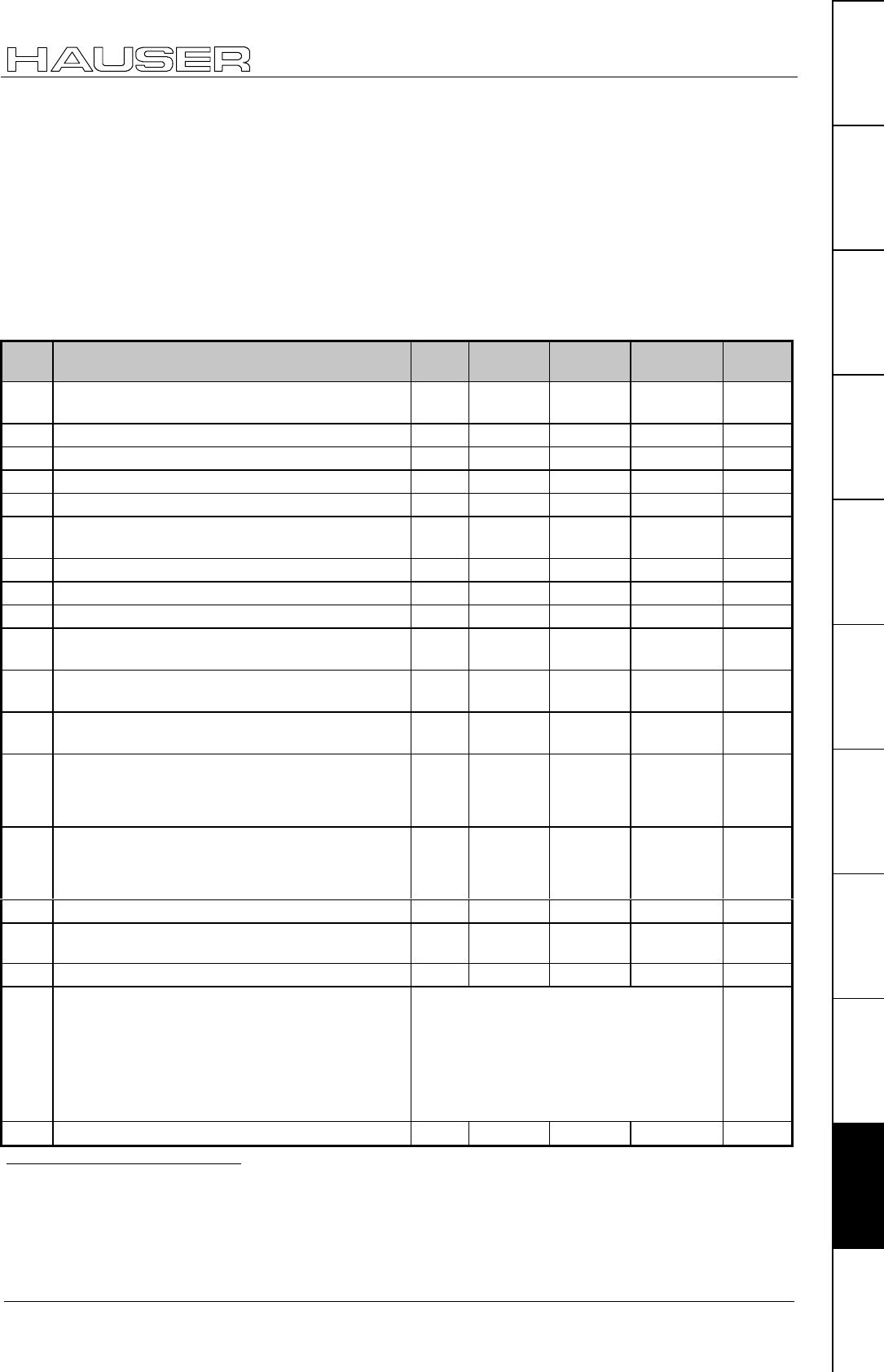
COMPAX parameter
213
Unit
hardware
Connector
assignment / cable
Technical dataConfigurationPositioning and
control functions
Optimization
functions
InterfacesAccessories /
options
StatusParameterError List:
Remark
The specified limit values refer to all parameters. Theoretical combinations are possible within these limits,
however they could cause an internal number overrun. The following limitation applies.
The travel per motor revolution must be greater than 0.01 mm or with increment unit: > 10 increments.
Travel per motor revolution:
♦
Spindle drive: P83;
♦
rack-and-pinion/toothed belt P82 * P83;
♦
general drive: P83 (/1000 in mm)
List of parameters, sorted by number
No. Meaning Unit Minimum
value Default
value Maximum
value Valid
from...
P1 Real – zero point (distance real zero-machine
zero).
corresp.
P90
-
1 000 000
0.00 +1 000 000 immediat.
P2 Substitute for non-programmed velocity. % 1.00 10.00 100.00 immediat.
P3 Velocity for find machine zero. % -100.00 10.00 100.00 immediat.
P4 Velocity for approach real zero. % 1.00 10.00 100.00 immediat.
P5 Velocity for processing by hand. % 1.00 10.00 100.00 immediat.
P6 Substitute value for non-programmed ramp
time.
ms 1 1000 60 000 immediat.
P7 Ramp time for approach machine zero. ms 1 1000 60 000 immediat.
P8 Ramp time for approach point of real zero. ms 1 1000 60 000 immediat.
P9 Ramp time for processing by hand. ms 1 1000 60 000 immediat.
P10 Ramp time after limit switch or emergency stop
is activated.
ms 1 250 60 000 immediat.
P11 Max. positive position referenced to machine
zero.
corresp.
P90
P12 +4 000 000.0
0
+4 000 000.00 VP
P12 Max. negative position referenced to machine
zero.
corresp.
P90
-
4 000 000.00
-
4 000 000.00
P11 VP
P13 Max. permitted lag tolerance (error E10 is
triggered when exceeded); E10 & E49 are
switched off with specification "0".
corresp.
P90
or % of
P10447
0 10.00 4 000 000.0
0
VP
"0"
immediat.
P14 Max. permitted positioning zone (applies for
message O5 : "Position reached")
corresp.
P90
or % of
P10448
0.00 1.00 4 000.00 VP
P15 Max. permitted velocity % 0.00 100.00 100.0049 VP
P16 Max. permissible torque % of
P105
0 200 300 VP
P17 Engine brake lag ms 0 0 4000 VP
P18 PLC data interface
Fast start via I15
Fast start via HEDA
Note!
Settings with bit 1 and bit 3 are only permitted
in COMPAX XX00.
Bit 050 =0 without PLC data interface
=1 with PLC data interface
Bit 1 =0 fast start via I15 not active
=1 fast start via I15 active
Bit 3 =0 no fast start via HEDA
=1 fast start via HEDA active
only permitted with P18 when bit 1=1!
VP
P19 RS232 Baud rate Bit/s 4800 960051 9600 Power on
47 In speed control mode in % of nominal speed (P104), otherwise corresponds to P90
48 In speed control mode in % of nominal speed (P104), otherwise corresponds to P90
49 For asynchronous motors, the maximum permitted velocity may be up to 300% of the nominal velocity.
50 Bit counting begins at bit 0.
51 By simultaneously pressing the three front plate keys when switching on, the baud rate is set to 9600.
With COMPAX 1000SL, the baud rate is always set to 9600.
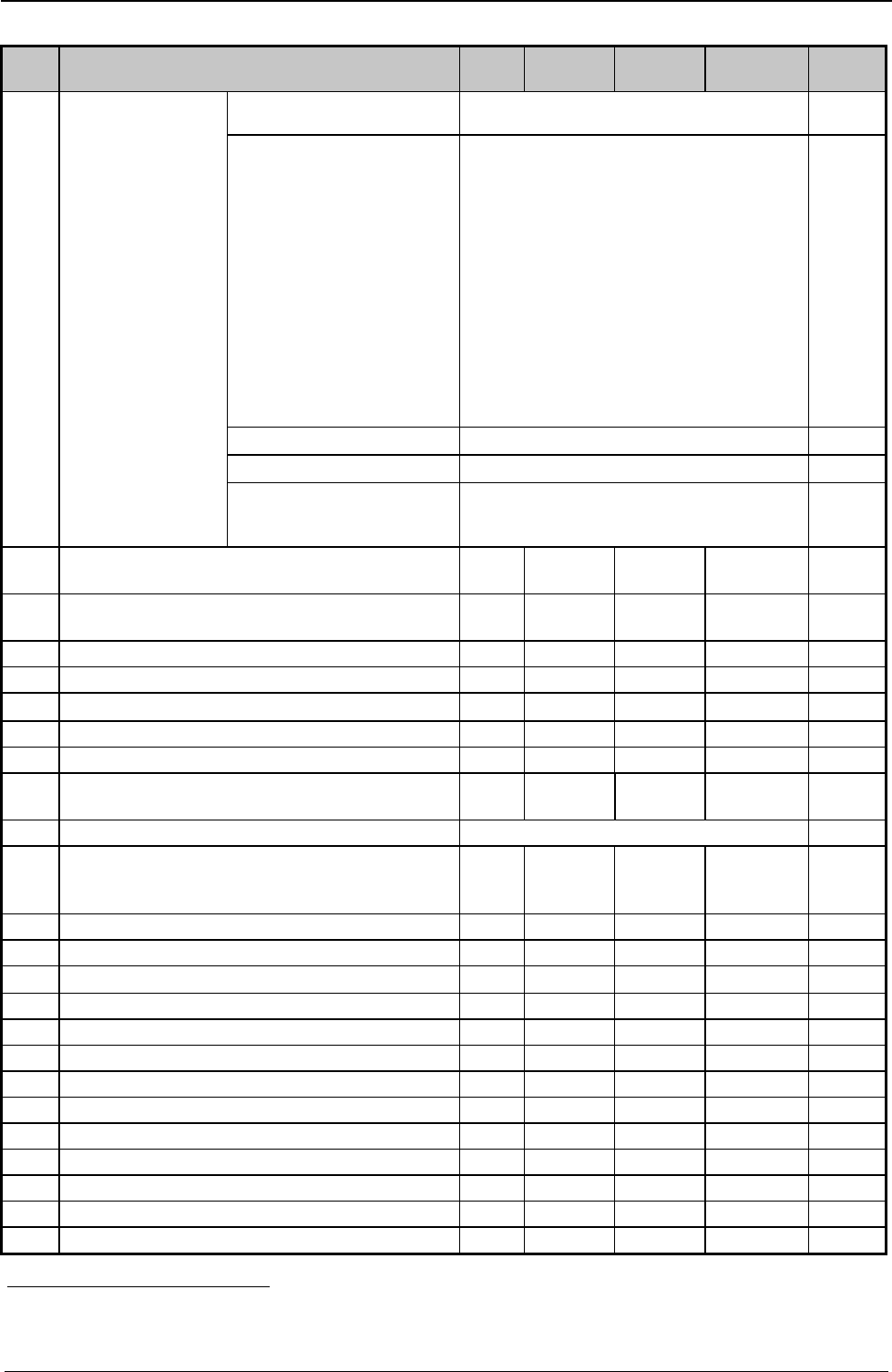
Appendix COMPAX-M/S
COMPAX standard parameters
214
No. Meaning Unit Minimum
value Default
value Maximum
value Valid
from...
P20 RS232 handshake Software handshake "0": without
"1": with XON, XOFF
Power on
P20 setting.
The sum of the
specified values is
entered in P20.
Error transmission /
negative command
acknowledgement
(E90 - E94)
"0": Error only with interface activity and if
the transmitted command triggers an
error.
No neg. command acknowledgement
(E90 - E94).
"2": no transmission of error and no neg.
command acknowl. (E90 – E94).
"4": Messages are indated for errors and
neg. command acknowl. (E90 – E94)
as soon as th. occur w. Exx CR LF >.
"6": errors & neg. command acknow.
(E90 – E94) only with interface
activity.
immediat.
End sign selection "0": CR LF > "8": CRPower on
Binary transfer "0": without "16": with immediat.
BCC: block check
EXOR via all signs apart
from the end sign
"0": without "128": with Power on
P21 Factor for influencing the travel per motor
revolution
0.1000 1.0000 10.0000 VP&VC
P22 Factor for modifying the speed which is
allocated to speed SPEED 100%.52
0.5000 1.0000 2.0000 VP&VC
P23 Stiffness of drive % 10 100 5000 VP
P24 Speed controller damping % 0 100 500 VP
P25 Speed – advance control value % 053 100 500 VP
P26 Acceleration – advance control value % 0 100 500 VP
P27 Moment of inertia % 10 100 500 VP
P29 Machine zero comparison Degre
e
0 0 360 VP
P35 Switch on mark reference "0": switched off "1": switched on VP
P36 Limitation of speed correction value for external
position adjustment (only COMPAX XX00 and
COMPAX XX30) ="0": switched off
% of
nominal
speed
(P104)
0 0 100 VP
P37 Minimum travel to mark corr.. P90 0.00 0.00 <P38 VP
P38 Maximum travel to mark corr.. P90 >P37 0.00 4 000 000.00 VP
P39 Maximum feed length corr..P90 ≥P38 0.00 <P11 or P12 VP
P40 Control parameters -4 000 000 0 +4 000 000 immediat.
P41 Control parameters -4 000 000 0 +4 000 000 immediat.
P42 Control parameters -4 000 000 0 +4 000 000 immediat.
P43 Control parameters -4 000 000 0 +4 000 000 immediat.
P44 Control parameters -4 000 000 0 +4 000 000 immediat.
P45 Control parameters -4 000 000 0 +4 000 000 immediat.
P46 Control parameters -4 000 000 0 +4 000 000 immediat.
P47 Control parameters -4 000 000 0 +4 000 000 immediat.
P48 Control parameters -4 000 000 0 +4 000 000 immediat.
P49 Control parameters -4 000 000 0 +4 000 000 immediat.
52 When motor nominal speeds have been modified, use this factor to perform a simple adaptation to the
current program.
53 When P93 = 4, P25 must be >0.
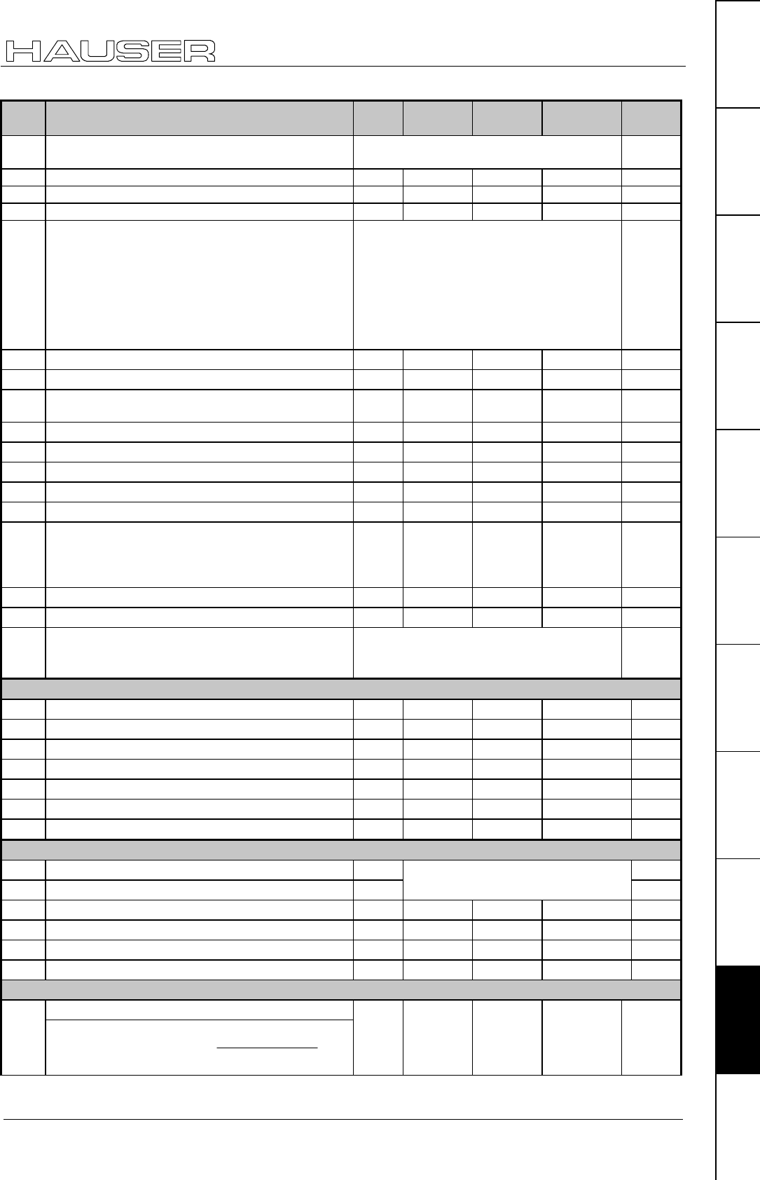
COMPAX parameter
215
Unit
hardware
Connector
assignment / cable
Technical dataConfigurationPositioning and
control functions
Optimization
functions
InterfacesAccessories /
options
StatusParameterError List:
No. Meaning Unit Minimum
value Default
value Maximum
value Valid
from...
P50 Enable speed monitor (=101) =100: without monitor (default setting)
=101: with monitor
VP
P56 D section rpm controller % 0 0 10 000 VP
P57 Filter acceleration % 0 100 550 VP
P58 Lag rapid rpm signal % 0 100 550 VP
P59 Structure switch measuring 0: Standard:
4: Variant 1 (for resolver)
3: Variant 2 (for SinCos)
8: Variant 3 (Rapid rpm controller)
+16: Sensitive stiffness (P23)
Larger setting range for P23
+65536: Sensitive D section (P56)
Larger setting range for P56
VP
P67 D-element slip filter % 0100 500 VP
P68 Slip filter lag % 0100 5000 VP
P69 Reverse advance control ("0" : without reverse
advance control)
%00 500 VP
P70 Current – advance control value % 0 0 500 VP
P71 D/A monitor 1 amplification 1 5 4 000 000 VP
P72 D/A monitor 2 amplification 1 10 4 000 000 VP
P73 Address of D/A monitor 1 0 4 18 VP
P74 Address of D/A monitor 2 0 15 18 VP
P75 Max. permitted measuring error (difference
betw. resolver pos. and external encoder pos.)
The external position localization is switched on with a
measuring error ≠ 0 and the internal position is corrected.
P90 0 0 4 000 000 VP
P76 Address of D/A monitor 3 (decimal place =0 ≡ amplification 1) 04.000 000 1 20 000 VP
P77 Address of D/A monitor 4 (decimal place =0 ≡ amplification 1) 015.000 000 1 20 000 VP
P80 Drive type "2": Spindle drive
"4/8": rack-and-pinion/toothed belt
"16": general drive / linear motor
VC
Drive type "Spindle drive" (P80="2")
P81 Length mm 0.00 0.00 5000.00 VC
P82 Diameter mm 8.00 0.00 80.00 VC
P83 Pitch mm 1.00 0.00 400.00 VC
P84 Moment of inertia for transmission and coupling kgcm20.00 0.00 200.00 VC
P85 Ratio 1.0000000 1.0000000 100.0000000 VC
P88 Max. translational mass moved kg 0 500 VC
P92 Min. translational mass moved kg 0 P88 VC
"Rack-and-pinion/toothed belt" drive type (P80="4/8")
P82 Tooth number Tooth number * tooth pitch VC
P83 Tooth pitch mm = 1.00 ........ 410.00 VC
P84 Moment of inertia for transmission and coupling kgcm20.00 0.00 200.00 VC
P85 Ratio 1.0000000 1.0000000 100.0000000 VC
P88 Max. translational mass moved kg 0 500 VC
P92 Min. translational mass moved kg 0 P88 VC
"General drive" drive type (P80="16")
Min. total moment of inertiaP81
With linear motors:
()
2
Π•2•1000
126•
=81 Pm
Pmin
kgmm20.00 0.00 Jmax.(82) VC
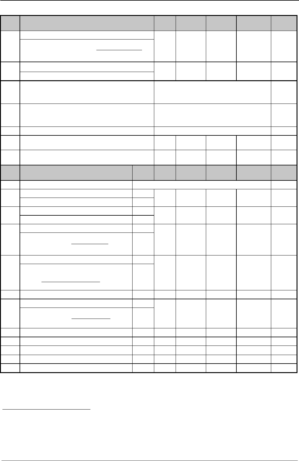
Appendix COMPAX-M/S
COMPAX standard parameters
216
No. Meaning Unit Minimum
value Default
value Maximum
value Valid
from...
Max. total moment of inertiaP82
With linear motors:
()
2
max
21000
126Pm
82P Π••
•
=
kgmm20 0.00 200 000 VC
Travel per motor revolutionP83
With linear motors: P83 = P126
µm or
increm.
10 0.00 4 000 000µm
65 536 Inkr.
VC
P90 Unit for travel "0": increments
"1": mm
"2": inch
VC
P93 Operating mode "1": normal mode
"2": Continuous mode
"4": speed control mode54
55
P94 Ramp shape "1": linear "2": smooth "3": quadratic. 56
P96 Transmission factor for the reset route of S2
option. ="0": no reset function.
-0 0 4095 VC
P98 Travel of axis per encoder revolution corresp.
P90
00.0000000 4 000 000 VC
No. Valid
for57
P100 Motor number Motor selection VC
Number of terminals A,SP101
Linear motor: P101=2 L
2212 VC
EMC SP102
P102=EMC[V/(m/s)] * P126/60 000 L
V * min/
1000 10 400 VC
Moment of inertia A,SP103
Linear motor:
()
2
21000
126
103 Π••
•
=Pm
PForcer L
kgmm
2
0 200 000 VC
Nominal speed A,SP104
Linear motor:
126
600001000
104 P
V
Palminno ••
=
L
min-1 500 9000 VC
P105 Nominal current A,S,L mA 200 100 000 VC
Nominal torque A,SP106
Linear motor:
()
Π••
•
=21000
126
106 PF
Palminno L
mNm 0 100 000 VC
P107 Pulse current A,S,L % 100 400 VC
P108 Max. time in current limit (P16) A,S,L ms 1000 5000 VC
P109 Stator inductivity A,S,L µH0 200 000 VC
P110 Magnetization current A mA 100 0.7 * P105 VC
P111 Rotor time constants A ms 5 2000 VC
54 When in speed control mode, P25 must > 0.
55 From next process command
56 From next process command
57 A: parameter for asynchronous motors
S: parameter for synchronous motors
L: parameter for linear motors
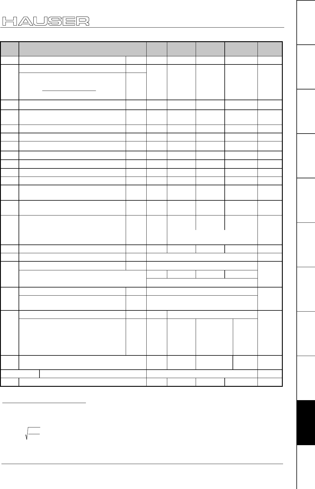
COMPAX parameter
217
Unit
hardware
Connector
assignment / cable
Technical dataConfigurationPositioning and
control functions
Optimization
functions
InterfacesAccessories /
options
StatusParameterError List:
No. Meaning Unit Minimum
value Default
value Maximum
value Valid
from...
P112 Slip frequency A mHz 100 20 000 VC
Maximum speed A,SP113
Linear motor:
126
60000•1000•
=113 P
V
Pmax
L
min-1 0 9000 VC
P115 Angular speed A % of
P104 50 100 200 VC
P116 Stator resistance A,S,L mOh
m
0 150 000 VC
P119 Start of saturation S,L % 70 100 <P120 VC
P120 End of saturation S,L % > P119 400 400 VC
P121 Minimum stator inductivity S,L % of
P109 10 100 100 VC
P122 Main inductivity A µH0 2 000 000 VC
P123 Rotor – scatter inductivity A µH0 200 000 VC
P124 Rotor resistance A mOhm 0 10 000 VC
P125 Nominal voltage A V 10 400 VC
P126 Pitch length of motor magnets in µm (2
* Pole distance)
L 20 000 100 000 VC
P127 Denominator: Dash count linear
encoder per pitch length (see P133)
L- 0 1 <P133 VC
P128 Cut-off value of temperature sensor for
E48
A,S,L Ω0 0 20 000 VC
"0": HDX / HDY – motors
"1270": HJ – motors
P129 Resolver offset A,S,L Degree 0 0 360 VC
P130 Resolver frequency A,S,L "2":5kHz(P4) VC
Resolver – transformation ratio58 A,S,L "2": ü = 0.5 (e.g. P4 resolver)
% 70 100 200
P131
Level adaptation (1/ü) for resolver or SinCos -
sensor (from V5.61) setting aids:59 100% ≡ 0.5; 200% ≡ 0.25; 70% ≡ 0.71;
VC
Position sensor A,S "2": 2-pol. resolver (P4)P132
With linear motors: L "10": TTL linear encoder
"11": SinCos linear encoder
VC
Sensor dash count A,S - 65 536P133
With linear motors: Dash count linear
encoder per pitch length (counter: see
P127)
Dash count per pitch length =
P133/P12760
L1/µm> P127 <
8388607
VC
P134 Nominal load capacity of the external ballast
resistance (100Ω) in [W]
Watts 260 8000 VC
P135 – P142 Bus – parameter
P143 Encoder pulses per revolution (channel 1) 128 4096 2 000 000 VC
58 Resolver transformation ratio = ü = resolver output voltage / resolver input voltage
59 The read-in level is displayed in the square of the channel 57 optimizing display.
With P233=57 this value is in S13. Meaning:
P131= %
S
.100
13
4050• (rounded to the nearest percent)
The current default setting "2" is still possible.
Note: Resolver with Ü=1 cannot be operated!
60 Select P133 as large as possible to achieve maximum accuracy. P133 does not have fractional digits.

Appendix COMPAX-M/S
COMPAX standard parameters
218
No. Meaning Unit Minimum
value Default
value Maximum
value Valid
from...
P144 Settting encoder channel 1 ="4": without external position
localization
="6": external position localization
switched on via channel 1.
VC
P146 Resolution of encoder emulation (channel 2) =0: 1024 =8: 512 VC
P148 End stage designation "Read only" – parameter ≡ S37
P149 Configuration "0": not valid "1": valid61 VC
P151 Responsiveness of the monitor control %0 30 500 VP
P156 Allocation of inputs I1...I6 to the input pins on
X19
Source for
Bit 0 – 3 input 1
Bit 4 – 7 input 2
Bit 8 – 11input 3
Bit 12 – 15 input 4
Bit 16 – 19 input 5
Bit 20 – 23 input 6
Bits -8388608 X19/2→I1
X19/3→I2
X19/4→I3
X19/5→I4
X19/6→I5
X19/7→I6
= 7 754 802
8388607 VP
P157 Allocation of inputs I7...I12 to the input pins on
X19
Source for
Bit 0 – 3 input 7
Bit 4 – 7 input 8
Bit 8 – 11input 9
Bit 12 – 15 input 10
Bit 16 – 19 input 11
Bit 20 – 23 input 12
Bits -8388608 X19/8→I12
I7 ... I11 = "0"
= -8 388 608
8388607 VP
P158 Allocation of inputs I13...I16 to the input pins on
X19
Source for
Bit 0 – 3 input 13
Bit 4 – 7 input 14
Bit 8 – 11input 15
Bit 12 – 15 input 16
Bit 16 – 19 free
Bit 20 – 23 free
Bits -8388608 X19/9→I16
I13...I15 ="0"
= 36 864
8388607 VP
P159 Allocation of output pins X19/15 ... X19/18 to
the logic outputs
Source for
Bit 0 – 3 Pin X19/15
Bit 4 – 7 Pin X19/16
Bit 8 – 11Pin X19/17
Bit 12 – 15 Pin X19/18
Bits 0O1→X19/15
O2→X19/16
O3→X19/17
O4→X19/18
= 12 816
65535 VP
P160 Allocation of output pins X19/19 ... X19/22 to
the logic outputs
Source for
Bit 0 – 3 Pin X19/19
Bit 4 – 7 Pin X19/20
Bit 8 – 11Pin X19/21
Bit 12 – 15 Pin X19/22
Bits 0O5→X19/19
O6→X19/20
O7→X19/21
O8→X19/22
= 30 292
65535 VP
P161 Maximum angle difference with absolute resolver
function
(4096 = 1 motor revolution)
1 100 2047 VP
P181 HEDA – parameter: coupling window (µm or
increments)
0 10 4 000 000 VP
P182 Setting status monitor S15 0 0 532 767 VP
61 When P149="0", all parameters apart from the bus settings P194, P195, P196, P250 are set to default values when switched on.
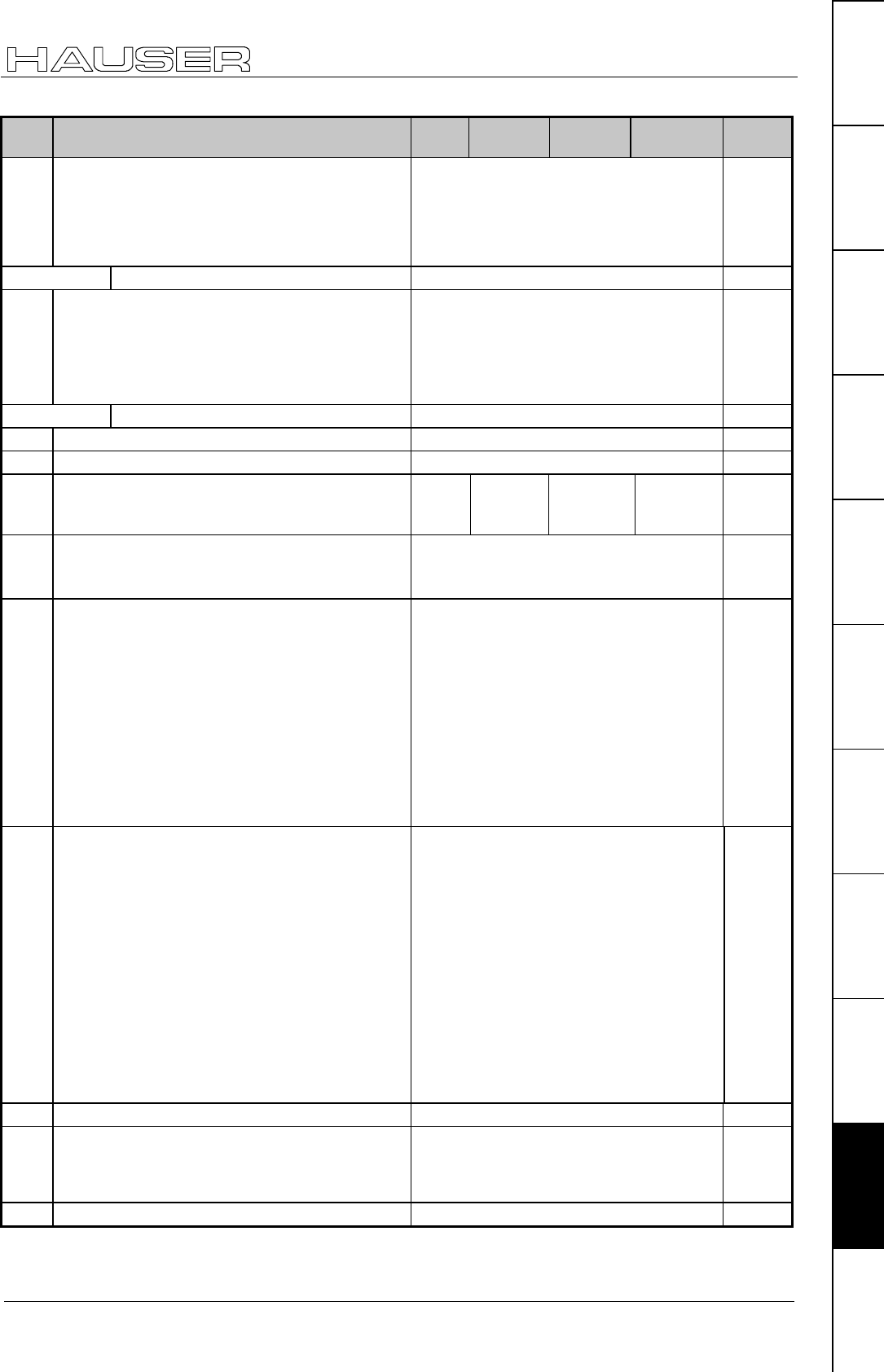
COMPAX parameter
219
Unit
hardware
Connector
assignment / cable
Technical dataConfigurationPositioning and
control functions
Optimization
functions
InterfacesAccessories /
options
StatusParameterError List:
No. Meaning Unit Minimum
value Default
value Maximum
value Valid
from...
P184 Selection parameters for HEDA – process value
(master)
Default value: P184=0
40: encoder position
42: internal time base
43: scaled master position
44: nominal pos. value in resolver increm.
45: actual pos. value in resolver increments
46: differentiated resolver position
VP
P185 – P187 HEDA – parameter
P188 Selection parameters for HEDA – process value
(slave)
Default value: P188=0
40: encoder coupling for encoder input
signals (P184=40)
140: encoder coupling for other input
signals (P184≠40)
42: internal time base
43: scaled master position
VP
P191 – P196 Bus – parameter
P197 Order (status S33) "Read only" – parameter
P198 Part (status S34) "Read only" – parameter
P202 With machine zero mode P212="8": Distance
machine zero – limit switch (setting "0"
corresponds to "3")
motor
revol. 3 0 255 VP
P206 Enables the absolute value sensor input / the
reset function of option S2 / absolute value
sensor
="1": absolute value sensor input enabled or
reset function switched on (S2 opt.)
= "2": absolute value sensor enabled
VP
P211 Disable and modify the Teach In – function
Also:
enable final stage with OUTPUT O0="0" without
lag (Bit 2="1")
"0" The teach data record and teach real
zero functions are enabled.
"1" Teach in real zero is blocked, data
record indicator is set to 1 using I1 + I4 .
"2" Teach in set is blocked, data record
indicator is set to 1 using I1 + I5 .
(Teach real zero is enabled)
"3" The teach data record and teach in real
zero functions are blocked. With I1 + I4,
Teach N or I1 + I5, the data record
indicator is set to 1.
"4...7": The final stage is enabled with
OUTPUT O0="0" without lag (P. 123)
immedia-
tely
P212 Machine – zero – mode
Settings "3" and "4" with COMPAX XX00 and
COMPAX XX30 only
"0": MZ equals external initiator & resolver
zero / 2 reversing initiators.
"1": MZ equals external initiator & resolver
zero.
"3": MZ equals external zero pulse
"4": MZ equals external initiator & external
zero pulse.
"5": MZ equals resolver zero
"6": reserved
"7": MZ equals external initiator (without
resolver zero).
"8": MZ equals limit switch
"10": teaches machine zero
"11": MZ equals initiator (without resolver
zero) / 2 reversing initiators.
immedia-
tely
P213 Machine zero direction "0": to the right "1": to the left VP
P214 Encoder direction "0": positive direction when encoder is
turning clockwise.
"1": positive direction when encoder is
turning anti-clockwise.
VP
P215 Direction of rotation "0": motor to the right "1": motor to the left VP

Appendix COMPAX-M/S
COMPAX standard parameters
220
No. Meaning Unit Minimum
value Default
value Maximum
value Valid
from...
P216 Limit switch position E1 is approached when
...
"0": motor turns clockwise
"1": motor turns anti-clockwise
immediat.
P217 Limit switch mode "0": without limit switch
"1": with limit switch (do not find during MZ)
"3": with limit switch (find during MZ)
"5": with limit switch (without pos. locking)
immediat.
P218 Error cutout
Default value: P218=0 (E57 active)
Bit 0 ="0" E57 active ="1" E57 switched
off
immediat.
P219 Emergency stop
input on COMPAX-
M / Synchronous
STOP on COMPAX
XX00
=0no evaluation of emergency stop input on COMPAX-M
=7 emergency stop input on COMPAX-M active
=128 synchronous STOP on COMPAX XX0X without evaluation of
emergency stop input on COMPAX-M
=135 synchronous STOP on COMPAX XX0X with evaluation of
emergency stop input on COMPAX-M
VP
P221 Freely assign
standard inputs I1
...I8 with "1"
Input (valency) [Bit No.]: E1 (1) [1] •
••
•E2 (2) [2] •
••
•E3 (4) [3] •
••
•E4 (8) [4]
E5 (16) [5] •
••
•E6 (32) [6] •
••
•E6 (64) [7] •
••
•E6 (128) [8]
P221 = sum of valencies of all required free inputs.
The control functions are assigned to the fieldbus with the bit set (I17 ... I24)
immedia-
tely
P222 Freely assign
standard inputs I9
...I16 with "1"
Input (valency) [Bit No.]: I9 (1) [1] •
••
•I10 (2) [2] •
••
•I11 (4) [3] •
••
•I12 (8) [4]
I13 (16)[5] •
••
•I14 (32)[6] •
••
•I15 (64)[7] •
••
•I16 (128)[8]
P222 = sum of valencies of all required free inputs.
The control functions are assigned to the fieldbus with the bit set (I25 ... I32)
immedia-
tely
P223 Assign outputs O1 -
O8 to the OUTPUT
WORD command
with a "1"
Output (valency) [Bit No.]: O1 (1) [1] •
••
•O2 (2) [2] •
••
•O3 (4) [3] •
••
•O4 (8) [4]
O5 (16) [5] •
••
•O6 (32) [6] •
••
•O7 (64) [7] •
••
•O8 (128) [8]
P223 = sum of valencies of the OUTPUT WORD outputs
immedia-
tely
P224 Assign outputs O9
- O16 to the
OUTPUT WORD62
command with "1"
Output (valency) [Bit No.]: O9 (1) [1] •
••
•O10 (2) [2] •
••
•O11 (4) [3] •
••
•O12 (8) [4]
O13 (16)[5] •
••
•O14 (32)[6] •
••
•O15 (64)[7] •
••
•O16 (128) [8]
P224 = sum of valencies of the OUTPUT WORD outputs
immedia-
tely
P225 Freely assign
standard outputs
with "1"
Output (valency) [Bit No.]: O1 (1) [1] •
••
•O2 (2) [2] •
••
•O3 (4) [3]
O4 (8) [4] •
••
•O5 (16) [5] •
••
•O6 (32) [6]
P225 = sum of valencies of all required free outputs.
immedia-
tely
P227 Assign special
functions to
outputs
Bit 163="0": O2 is assigned the default function (=no warning).
Bit 1="1": O2 is assigned the "Idle monitor" function.
Bit 4="0": O5 is assigned the default function (position reached with
evaluation of P14)
Bit 4="1": O5 is assigned with the "O5 toggles when position
reached" function.
immedia-
tely
P229 Speed threshold for "Idle display" function (only
switched on if P227 bit 1="1") ‰0 0 255 VP
P232 Function I11 =0: I11 can be freely assigned
With external position adjustment switched on (P75>0):
=4: I11 switches the external position adjustment
(I11="0": off and I11="1": switched on)
COMPAX 1060/70SL: With analogue ±10V – interface
=4: I11 has the function "Enable analogue input
(I11="0": Setpoint=0 I11="1": analogue input active)
VP
P233 Setting the optimization display S13 1...255 immedia-
tely
P234 Setting the optimization display S14 1...255 immedia-
tely
62 OUTPUT WORD – command is available with bus systems.
63 Bit-counting starts with Bit 0.

COMPAX parameter
221
Unit
hardware
Connector
assignment / cable
Technical dataConfigurationPositioning and
control functions
Optimization
functions
InterfacesAccessories /
options
StatusParameterError List:
No. Meaning Unit Minimum
value Default
value Maximum
value Valid
from...
P243 HEDA operation
mode
="0": single axis (when P250=0) or slave on IPM (P250=1 ... 9)
="1": COMPAX as master ="2": COMPAX as slave on a COMPAX master
VP
P245 Assign outputs O1
- O8 to the HEDA
bus
Output (valency) [Bit No]: O1 (1) [1] •
••
•O2 (2) [2] •
••
•O3 (4) [3] •
••
•O4 (8) [4]
O5 (16) [5] •
••
•O6 (32) [6] •
••
•O7 (64) [7] •
••
•O8 (128) [8]
P245 = sum of valencies of the outputs allocated to the HEDA bus
immedia-
tely
P246 Assign outputs O9
- O16 to the HEDA
bus
Output (valency) [Bit No]: O9 (1) [1] •
••
•O10 (2) [2] •
••
•O11 (4) [3] •
••
•O12 (8) [4]
O13 (16)[5] •
••
•O14 (32)[6] •
••
•O15 (64)[7] •
••
•O16 (128) [8]
P246 = sum of valencies of the outputs allocated to the HEDA bus
immedia-
tely
P247 - P250 HEDA parameter VP
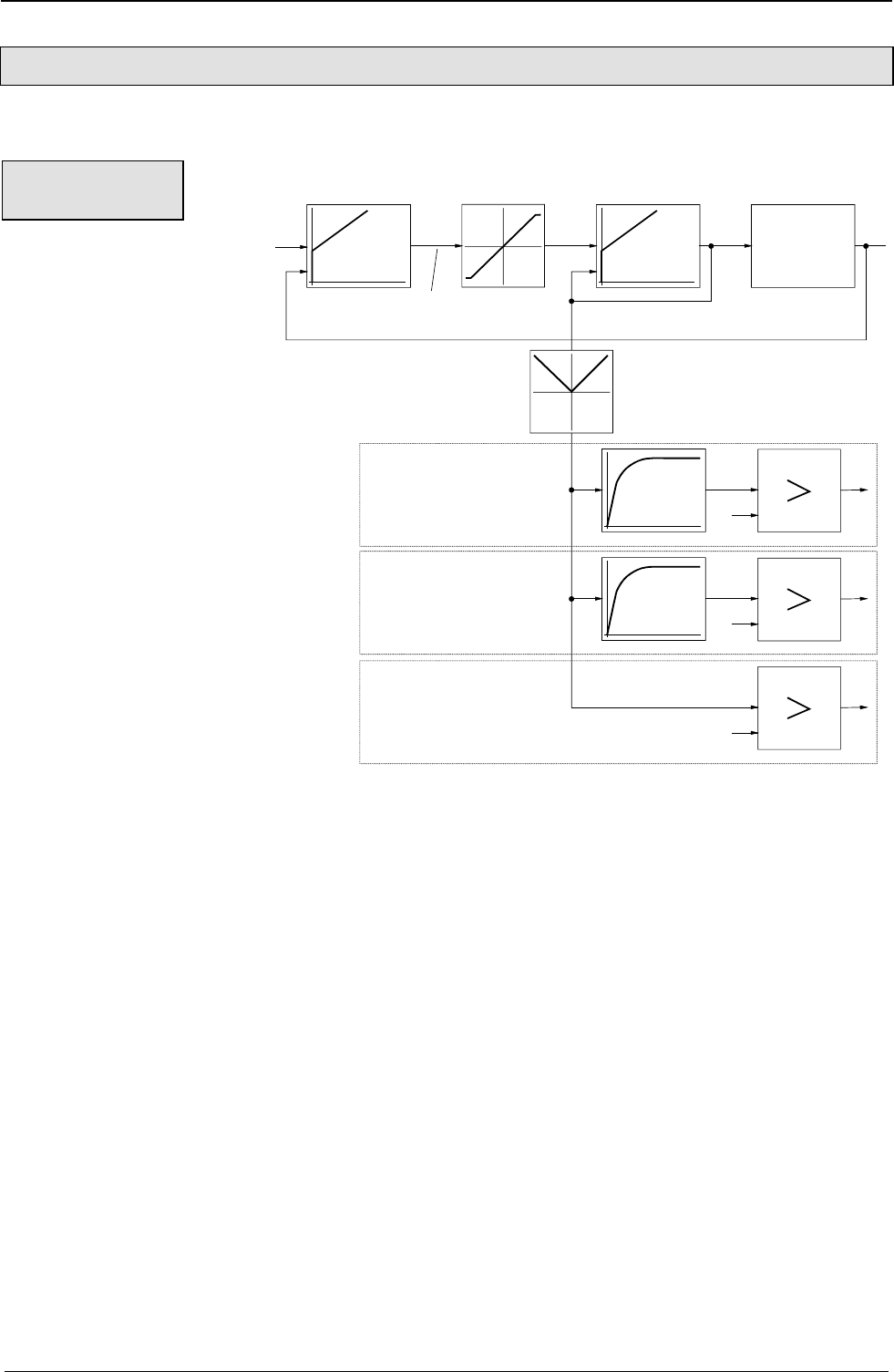
Appendix COMPAX-M/S
Monitoring and limitation characteristics
222
10.3.3 Monitoring and limitation characteristics
This section examines the relationships of COMPAX monitoring and limitation characteristics in more detail:
device supervision
Motor supervision
power output stage supervision
rate determination
current limit
min [IGS, P107*P105,P16*P105]
current control with
power output stage
speed control
motor
Hardware
Software
Software
1,5*IGS
1,1*IMnenn
IGnenn
E53
E53
E41
TG
TM
...
current actual value
current reference value
IUnom.: unit nominal current IUP: unit peak current IMnom.: motor nominal current
Dynamic monitoring:
In COMPAX, the nominal current value is limited to the smallest value of the following 3 quantities.
♦
IUP:♦
unit peak current
♦
P105 * P107: ♦
nominal motor current (P105) * maximum pulse current permitted for the motor (P107)
♦
P105 * P16: ♦
nominal motor current (P105) * maximum permitted (user-set) torque (P16)
Static monitoring
This executes triple monitoring:
Unit monitoring Using the unit-specific time constant TG, a current greater than
IUnom. is permitted for a specific period; E53 then switches the unit
off.
Motor monitoring Using the time constant TM, a current greater than 1.1 * IMnom. is
permitted for a specified period; E53 then switches the unit off.
TM is set so that the pulse current P107 can flow for the period set
in P108.
Final stage / short circuit monitoring Absolute monitoring to 1.5 * IUP.
Structural
diagram:
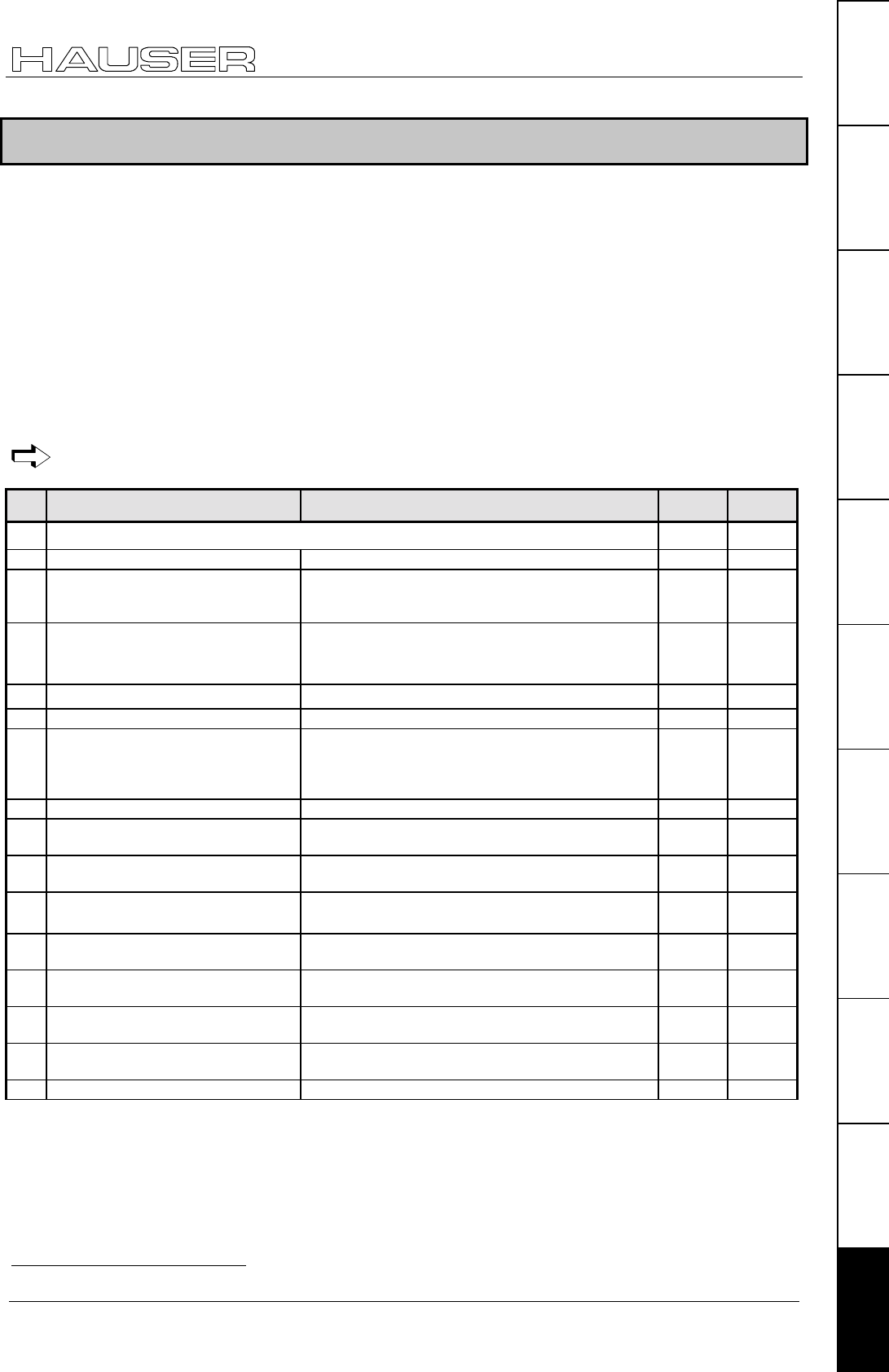
Error handling and error messages
223
Unit
hardware
Connector
assignment / cable
Technical dataConfigurationPositioning and
control functions
Optimization
functions
InterfacesAccessories /
options
StatusParameterError List:
10.4 Error handling and error messages
♦
All errors are indicated by messages on the front plate error LED.
♦ An error number EXX appears in the display. You can modify parameters when an error message is present.
♦
When you have rectified the cause of the error, acknowledge the error using Enter, Quit or by switching the
unit on again (Power on).
♦
When the LED (error) turns off, COMPAX is ready for operation.
♦
Switch off COMPAX if you are experiencing hardware errors (e.g. short circuit to outputs).
♦
The errors I1...I57 are also reported with the binary output O1="0"; the drive does not accept any
positioning commands and the ready contact is opened.
♦ If COMPAX executes a travel motion, the drive is then decelerated using the programmed ramp time (for E50, E51 and E55
using ramp time P10) and, if specified in the error table, the unit is switched off after this time.
♦
The errors ≥ E58 are also indicated with the binary output O2="0" (if O2 is configured in this manner, see
parameter P227).
If the specified measures cannot rectify the problem, there may be an electrical defect. Please send
the unit and an error description to HAUSER.
No. Cause Action Acknow-
ledge with Drive
volt.-free
E00 Interruption of a positioning command using STOP / BREAK; is only reported via RS232. Not
necessary no
E01 Not configured. Configure. Quit yes
E05 Machine zero initiator not found.
Error is only generated when using
reversing initiators.
Check initiator. Quit no
E07 Calculation error Check programmed arithmetic.
(more accurate cause shown in the optimizing
display P233/243=39; see Page 133)
Quit no
E08 Synchronous STOP present Check P219 Quit no
E09 Drive not running. Remove mechanical blockage (tools, foreign bodies). Quit no
E10 Lag error too large.
or
speed difference too great
Check mechanics for smooth operation, reduce load
or feed force or increase P13.
This error message can be turned off by setting
P13="0".
Quit see
below
E11 Programmed position not reached. Remove mechanical obstacles or increase P14. Quit no
E15 Error in 2nd position measuring
system.
Check configuration and wiring. Quit yes
E16 The data record number selected
does not exist.
Select data record number between 1...250. Quit no
E17 The data record number selected is
too large.64
Select data record number between 1...250. Quit no
E18 The maximum data record 250 is
already assigned.
Free data record 250. Quit no
E19 No space available in data record
memory.
Delete data records or entire data record memory. Quit no
E20 Target position beyond positive end
limit.
Correct target position. Quit no
E21 Target position beyond negative end
limit.
Correct target position. Quit no
E22 Machine zero is not approached. Find machine zero. This must be found after power on. Quit no
64 with COMPAX 70: Curve number not present.
Appendix COMPAX-M/S
Monitoring and limitation characteristics
224
No. Cause Action Acknow-
ledge with Drive
volt.-free
E23 The current command is not allowed. ♦
Positioning command in the speed control mode.
♦
Approach MZ in speed control mode.
♦
Travel command when drive is switched off.
♦
Hand +/- when an error is present.
♦
More than 8 consecutive comparator commands
(preparatory commands) in the data record
memory.
Quit no
E24 The speed selected is not valid. Enter speed between 0...100%. Quit no
E25 The position selected is not valid. Note end limits and "Software end limit monitoring"
chapter in variant documentation.
Quit no
E26 REPEAT without END or GOSUB
without RETURN .
Insert END / RETURN command. Quit no
E27 Parameter must not be written. Check parameter. Quit no
E29 Motor values missing. Send unit to HAUSER. Quit yes
E30 Hardware fault. Remove extreme external sources of fault. Quit yes
E31 Error in parameters. Check parameter. Quit no
E32 Error in parameters. Check parameter. Quit no
E33 Error in program memory. Check data record memory. Quit no
E34 Error in program memory. Check data record memory. Quit no
E35 Hardware fault. Remove extreme external sources of fault. Quit no
E36 Hardware fault. Faulty or incorrect unit hardware. Power on yes
E37 Auxiliary voltage +15 V missing. Switch on again. Power on yes
E38 Voltage in intermediate circuit too
high; e.g. if braking output is too
high. Limits:
COMPAX 25XXS: >400V
COMPAX 10XXSL: >400V
otherwise: >800V
Increase braking and idle times / check mains power.
COMPAX 25XXS: external ballast resistance
missing.
COMPAX 45XXS/85XXS: bridges X2/5 - X2/6
missing.
COMPAX 1000SL: Check value P134.
Quit yes
E39 Temperature too high (>85°), cycle
too hard.
Increase acceleration times. Quit yes
E40 Input "Enable final stage" (45/85S: X3/1-/2; 1000SL X19/24-X19/12, 35XXM: X19/9-/10) not assigned
Only with COMPAX 35XXM, COMPAX 45XXS, COMPAX 85XXS and COMPAX 1000SL!
Note!
With E40 there is no braking delay; the final stage is immediately switched off.
The input has a direct effect on the hardware.
Quit yes
E41 Final stage reports error.
COMPAX 35XXM: Short circuit of the
ballast resistance or undervoltage
24V
COMPAX 1000SL:
Overvoltage or ballast switching
Check motor and cable for ground fault, short circuit
fault and function; remove extreme external sources
of fault.
Quit yes
E42 Resolver / sensor error. Check resolver cable and connector for correct
connections and faults.
A special error code can be found in channel 67 of
the optimization display. This means
Error No. 1 ... 30: Sensor indicates error
Error No. > 30: COMPAX indicates error
Error No. =160: Sensor level too high
Error No. =161: Sensor level too low
(implement level adaptation using parameter P131)
Quit yes
E43 Output overloaded. Check I/O cables, connectors and external circuits.
Note load limits (refer to start-up manual).
Quit yes
E44 Positive auxiliary voltage outside
tolerances.
Switch unit on again. Power on yes
E45 Negative auxiliary voltage outside
tolerances.
Switch unit on again. Power on yes
E46 Supply voltage +24V is too high. Check +24V DC power unit. Power on yes
E47 Supply voltage +24V is too low. Check +24V DC power unit. Power on yes
Please note: the operating instructions (pages 67 - 171) as well as the application examples (pages
225 - 237) can be found in the complete product manual which is available as PDF file on CD
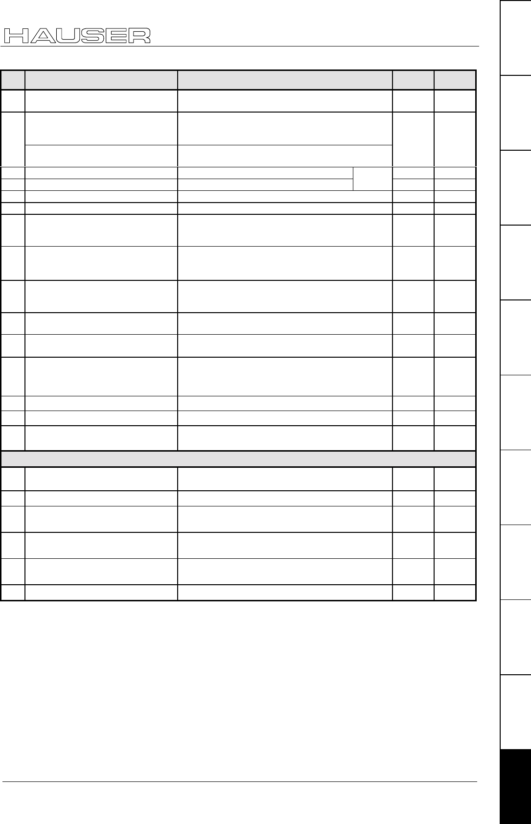
Error handling and error messages
225
Unit
hardware
Connector
assignment / cable
Technical dataConfigurationPositioning and
control functions
Optimization
functions
InterfacesAccessories /
options
StatusParameterError List:
No. Cause Action Acknow-
ledge with Drive
volt.-free
E48 Motor thermostatic switch reports
error.
Check resolver cable, motor type and motor / remove
external sources of heat.
Power on yes
E49 Motor or drive reports blockage.
Drive remains in the current limit
(P16) for longer than P108
Free mechanics. This error message can be
switched off by setting P13="0".
Check motor cable.
Quit yes
COMPAX-S: speed controller
oscillating
Optimize controller (reduce P23 stiffness).
E50 Limit switch 1 activated. Move by hand or POSA from limit switch. Quit no
E51 Limit switch 2 activated. Move by hand or POSA from limit switch.
see
P217 Quit no
E52 Error in emergency stop circuit. Check emergency stop switch contacts. Quit yes
E53 Motor overloaded. Check dimensions. Quit yes
E54 Speed higher than the maximum
motor speed or higher than P15 *
1.21
Reduce nominal speed or, if speed is too high due to
harmonies, optimize controller.
Quit yes
E55 External emergency stop.
Intermediate circuit not enabled.
Temperature overload.
Check system, then switch unit on again.
Voltage must be at least 2s >320V.
External load too great.
Quit yes
E56 Emergency stop directly in
COMPAX-M via X9/6 (switched on
via P219=7)
Check system, then switch unit on again. Quit yes
E57 Voltage in intermediate circuit too
low (<70V).
Check mains connection.
Switch off E57 using P218 ="1".
Quit yes
E58 Temperature is too high (>75°) or
SinCos - temperature error
Increase acceleration times. Quit no
E65 Encoder error Check encoder cable.
Axis is brought to a stop through speed control.
(switch off using P218)
Quit no
E76 HEDA synchronisation interrupted Check physical connection and P249 Quit no
E77 HEDA transmission error Check physical connection and P247 Quit no
E78 Successive HEDA transmission
errors
Check physical connection and P248 Quit no
Negative command acknowledgement (only for warnings)
E72 Block Check Character - error or
general fault.
Re-send the characters *no
E90 Syntax error; command not valid Check command structure. *no
E91 Command cannot be executed in this
COMPAX operating mode.
Check COMPAX status *no
E92 Function running, command cannot
be executed
*no
E93 Data record memory active,
command cannot be executed
*no
E94 Password missing *no
* Quit is not required.
Response to lag error (error E10)
Position controller
COMPAX is switched from position control mode to speed control mode and speed 0 specified. The drive
remains powered. (Does not apply for COMPAX xx60)
The next move command after the error acknowledgement brings the system back to position control.
Response to E15
COMPAX is switched from position control mode to speed control mode and speed 0 specified. The drive
remains powered.
Speed controller
In speed control mode, control is referenced to speed 0.

Application examples COMPAX-M/S
Overview
226
11. Application examples
11.1.1 Overview
External data record selection....................................................................................................227
Application:
One of eight various workpieces should be made available at a data collection station. The number of the
desired workpiece is set using a BCD selector switch. The transportation process is then triggered by a
starting pulse.
Mark-referenced positioning.......................................................................................................229
Application:
Pieces with lengths of between 100 mm and 500 mm should be cut from a plate roller. The cut-off
positions are specified by marks on the plate. If two marks are separated by more than 500 mm, the plate
should be pulled back to the last cut-off position.
Speed step profiling / comparator switching points ................................................................231
Application:
A bore spindle should be guided to the surface of the workpiece using a rapid feed movement. The bore
is then bored to a defined depth using a considerably longer feed. When reversing the bore spindle, the
unit should travel at a slow velocity while the drill is still in the bore. The remaining travel to the idle
position is performed at a rapid speed.
The bore spindle should be switched on just before the boring process commences and should be
switched off immediately after it has been removed from the bore. Movement of the conveyor belt should
be blocked for as long as there is a risk of collision between the workpiece and drill.
SPEED SYNC................................................................................................................................233
Application:
Cartons should be transferred from one conveyor belt (conveyor belt A), a belt operating at a very
variable belt speed, to another conveyor belt (conveyor belt C), a belt which has a constant belt speed.
This task should be performed using a transfer belt (conveyor belt B) installed between the two other
belts. This belt receives cartons from conveyor belt A and, when triggered by a pulse, passes them on to
conveyor belt B. In addition to this, when conveyor belt B is assigned, conveyor belt A should be blocked.
Conveyor belt B is controlled by COMPAX.
Speed control mode ....................................................................................................................234
Application:
A centrifuge for manual operation should be operated by an operating mode switch. The centrifugal
process should either be run at a permanently set speed or the test tubes should be removed, one after
another, through the removal aperture. The shutter on the removal aperture must only be able to open
when the centrifuge is at a standstill.
Fast start.......................................................................................................................................236
Application:
Material should be fed to an extender stamping machine which operates at a maximum speed of 150
rpm. The material may only be supplied if the stamping tool is open and if the workpiece (already
stamped) has been thrown up. The material supply should be released or blocked via a switch.
Implementing a torque converters.............................................................................................237
2 options are available for implementing a torque converters.
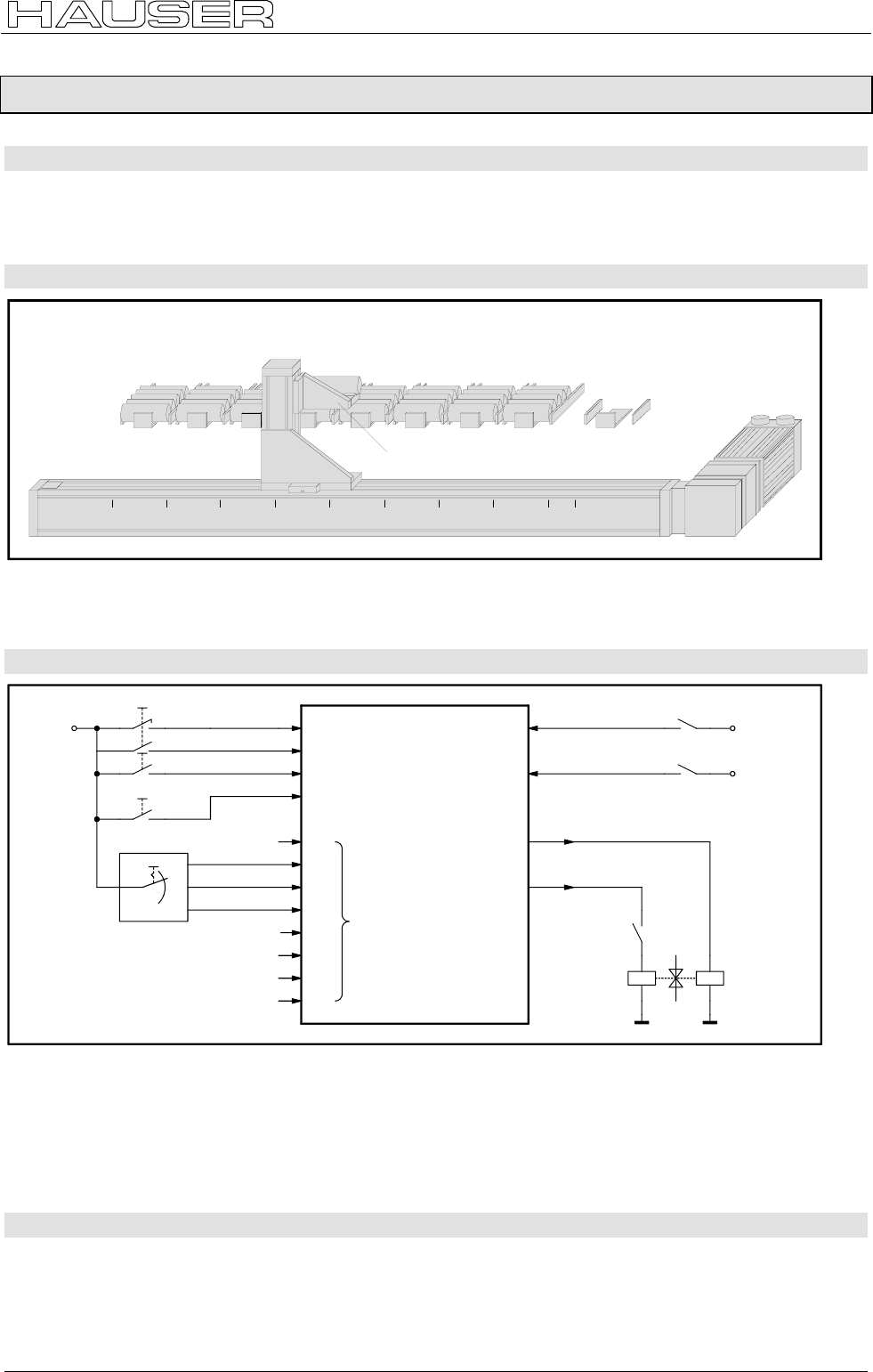
External data record selection
227
11.1.2 External data record selection
Application:
One of eight various workpieces should be made available at a data collection station. The number of the
desired workpiece is set using a BCD selector switch. The transportation process is then triggered by a
starting pulse.
Assignments:
station
7
removal
station
station
6
station
5
station
4
station
3
station
2
station
1
station
0
+960 +840 +720 +600 +480 +360 +240 +120 0-60
workpiece pick-up
The horizontal movement is implemented using an NC axis controlled by COMPAX. A pneumatic cylinder,
which is controlled by COMPAX using a double solenoid valve, raises and lowers the workpiece pick-up.
COMPAX performs all the functions required without superordinate control.
Wiring up the digital inputs and outputs:
I1
I2
I5
I6
I10
I11
I12
I13
O7
O8
I9
I14
I15
I16
search MZ
start
stop
BCD-switch
I7
I8
pick-up lifted
pick-up lowered
lower
pick-up
lift
pick-up
evaluation by
external calling
of command lines
removal
station empty
1
2
4
BCD
+24V +24V
+24V
COMPAX
+24V
Comments:
♦
The inputs I9, I14, I15 and I16 have to be placed on GND or left open.
♦
The BCD switch has eight settings. The outputs are encoded with binary.
♦
The "Data collection station empty" switch is closed when the data collection station is closed. The switch
operation prevents the workpiece pick-up being lowered for as long as there is a workpiece in the data
collection station.
Function:
The first event after COMPAX has been started is the approaching of the data collection station. If the
workpiece pick-up is not lowered, the assumption is made that there is still a workpiece in the workpiece
pick-up. This is deposited in the data collection station by lowering the workpiece pick-up. The system is now
ready for the first transportation process.

Application examples COMPAX-M/S
External data record selection
228
To move one particular workpiece to the data collection station, the number of the station in question is first
set on the BCD switch. The process is then triggered by a start pulse. To do this, the BCD switch setting
must remain the same until the start of the first axis movement. The lowered workpiece pick-up is positioned
under the station which is specified by the BCD switch. When the workpiece pick-up is raised, the front
workpiece is taken out of the station. The axis returns to the data collection station. The workpiece pick-up is
lowered there. The workpiece is thereby deposited in the data collection station. COMPAX now waits for the
next transportation process.
Programming:
Configuration:
P93 =+1 i.e. normal operating mode (absolute and relative positioning)
Names of inputs and outputs:
I7 pick-up raised 0 # no 1 # yes
I8 pick-up lowered 0 # no 1 # yes
O7 raise pick-up 0 # off 1 # on
O8 lower pick-up 0 # off 1 # on
List of programs:
N001: SPEED 50 ............................................... ;sets the speed
N002: ACCEL 500..............................................;sets the acceleration and braking ramps
N003: OUTPUT O7=0 ........................................ ;pick-up raise function = off
N004: OUTPUT O8=0 ........................................ ;pick-up lowering function = off
N005: POSA -60................................................. ;moves to data collection station
N006: IF I8=0 GOSUB deposits workpiece (36). ;if pick-up is not lowered: deposits workpiece
Wait for START: ........................................... ;mark
N007: WAIT START........................................... ;waits for the start pulse
N008: GOSUB EXT............................................ ;calls up the corresponding inputs I9-I16 for the sub-program
N009: GOSUB raises workpiece (32)................. ;calls "Raise workpiece" sub-program
N010: POSA -60................................................. ;proceeds to data collection station
N011: GOSUB deposits workpiece (36)............. ;calls up "Deposit workpiece" sub-program
N012: GOTO waits for START (7)...................... ;goes to data record N007
........................................................................... ;Link table for external data record selection
N016: POSA 120................................................;proceeds to station 0
N017: RETURN.................................................. ;returns to main program
N018: POSA 240................................................;proceeds to station 1
N019: RETURN.................................................. ;returns to main program
N020: POSA 360................................................;proceeds to station 2
N021: RETURN.................................................. ;returns to main program
N022: POSA 480................................................;proceeds to station 3
N023: RETURN.................................................. ;returns to main program
N024: POSA 600................................................;proceeds to station 4
N025: RETURN.................................................. ;returns to main program
N026: POSA 720................................................;proceeds to station 5
N027: RETURN.................................................. ;returns to main program
N028: POSA 840................................................;proceeds to station 6
N029: RETURN.................................................. ;returns to main program
N030: POSA 960................................................;proceeds to station 7
N031: RETURN.................................................. ;returns to main program
Raise workpiece :......................................... ;mark
N032: OUTPUT O7=1 ........................................ ;activates "Raise" solenoid valve
N033: IF I7=0 GOTO 33..................................... ;waits until workpiece pick-up is raised
N034: OUTPUT O7=0 ........................................ ;deactivates "Raise" solenoid valve
N035: RETURN.................................................. ;returns to main program
Deposit workpiece :...................................... ;mark
N036: OUTPUT O8=1 ........................................ ;activates "Lower" solenoid valve
N037: IF I8=0 GOTO 37..................................... ;waits until the workpiece pick-up is lowered
N038: OUTPUT O8=0 ........................................ ;deactivates "Lower" solenoid valve
N039: RETURN.................................................. ;returns to main program
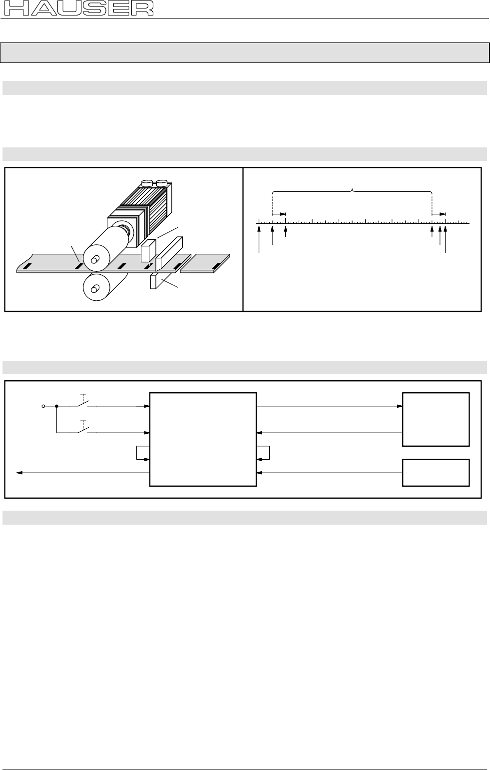
Mark-referenced positioning
229
11.1.3 Mark-referenced positioning
Application:
Pieces with lengths of between 100 mm and 500 mm should be cut from a plate roller. The cut-off positions
are specified by marks on the plate. If two marks are separated by more than 500 mm, the plate should be
pulled back to the last cut-off position.
Assignments:
label
light
barrier
shears
A
50mm
P38 = +650
P39 = +680
label window: range within which labels are detected
initial position B
P37 = +50
P39
P38
P37: minimum distance to label.
: maximum distance to label.
: maximum feed if no label appears
within the window.
A:
POSR 50mm
POSR
position if label
appears at 50mm.
B : position if label
appears at 650mm.
The plate is fed by a roller feed controlled by COMPAX. A reflex light barrier detects the marks on the plate
and reports this to COMPAX. The distance between the light barrier and the shears is 50 mm. The shears
are controlled and monitored by COMPAX.
Wiring up the digital inputs and outputs:
I5
I6
+24V start
stop
O7
I7
COMPAX
O15
massage 1 = label missing
0 = label detected I15
O16
shears 0 = block
1 = activate
shears 0 = block
1 = open
O14
I14
I16 label input 0 = no label
1 = label
shears
light
barrier
Function:
The first event after COMPAX has been started is a rest of the control outputs. Once assurance has been
received that the blades of the shears are open, COMPAX is ready for the initial cutting to length.
The cutting to length process is triggered by a start pulse. COMPAX firstly activates the mark reference (I14)
using O14. After a waiting time of 10 ms (which is used to compensate for any possible COMPAX timing
offset), the mark-referenced positioning process is started using the "POSR 50 mm" command. The mark
input (I16) is approved after a travel distance of 50 mm (P37). If the light barrier now detects a mark,
COMPAX pushes the plate another 50 mm. This distance corresponds to the distance between the light
barrier and the shears and is programmed using "POSR 50 mm". If no mark has been detected after a travel
distance of 650 mm (P38), COMPAX stops the feed movement after a total of 680 mm (P39).
At the end of the positioning process, output O16 indicates whether a mark has been detected within the
mark window or not. This output is queried using I15.
If I15 is at 1 (i.e. mark found), COMPAX sets the message output O15 to 0 and activates the shears. Once
the blades have opened, COMPAX waits for the next start pulse. If I15 is 0 (i.e. no mark found), COMPAX
sets the message output O15 to 1, blocks the mark reference (I14) via O14, pulls the plate back by 680 mm
to the last cut-off position and waits for the next start pulse.

Application examples COMPAX-M/S
Mark-referenced positioning
230
Programming:
Configuration:
P93 =+2 i.e. continuous operating mode
P35 =+1 i.e. mark reference switched on
P37 =+50 i.e. minimum travel to mark = 50 mm
P38 =+650 i.e. maximum travel to mark = 650 mm
P39 =+680 i.e. maximum feed length, if no marks appear in the mark window = 680 mm
Names of inputs and outputs:
I7 shears 0 # closed 1 # open
I15 mark 0 # missing 1 # found
O7 shears 0 # block 1 # activate
O14 mark reference 0 # block 1 # activate
O15 message 0 # mark found 1 # mark missing
List of programs:
N001: SPEED 50 ............................................... ;sets the speed
N002: ACCEL 250..............................................;sets the acceleration and braking ramp
N003: OUTPUT O7=0 ........................................ ;shears = block
N004: OUTPUT O14=0 ...................................... ;mark reference = block
N005: OUTPUT O15=0 ...................................... ;message = mark found
Wait for start:................................................ ;mark
N006: IF I7=0 GOTO 6....................................... ;waits until shears are open
N007: WAIT START........................................... ;waits for start pulse
N008: OUTPUT O14=1 ...................................... ;activates mark reference
N009: WAIT 10................................................... ;waits until mark reference is activated
N010: POSR 50 ................................................. ;mark-referenced positioning
N011: WAIT 10................................................... ;waits until mark is missing or set
N012: IF I15=0 GOTO reverses (18).................. ;if mark is missing, reverses plate
N013: OUTPUT O15=0 ...................................... ;sets "Mark found" message
N014: OUTPUT O7=1 ........................................ ;activates shears
N015: IF I7=1 GOTO 15..................................... ;waits until shears are closed
N016: OUTPUT O7=0 ........................................ ;blocks shears
N017: GOTO waits for start (6) .......................... ;goes to data record N006
Reverse:....................................................... ;mark
N018: OUTPUT O15=1 ...................................... ;sets "Mark missing" message
N019: OUTPUT O14=0 ...................................... ;blocks mark reference
N020: WAIT 10................................................... ;waits until mark reference is blocked
N021: POSR -680 .............................................. ;returns to start point
N022: GOTO waits for start (6) .......................... ;goes to data record N006
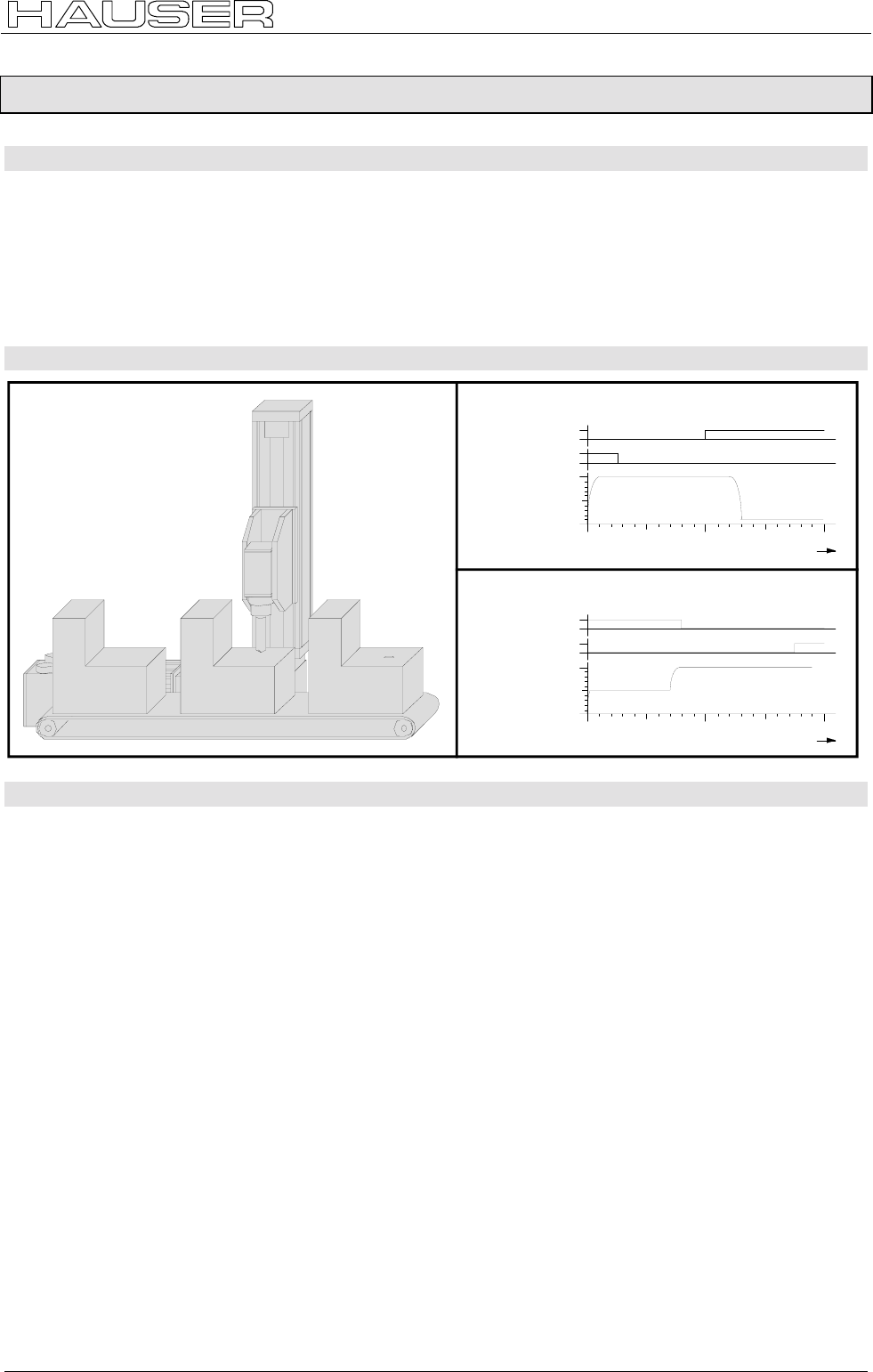
Speed step profiling / comparator switching points
231
11.1.4 Speed step profiling / comparator switching points
Application:
A bore spindle should be guided to the surface of the workpiece using a rapid feed movement. The bore is
then bored to a defined depth using a considerably longer feed. When reversing the bore spindle, the unit
should travel at a slow velocity while the drill is still in the bore. The remaining travel to the idle position is
performed at a rapid speed.
The bore spindle should be switched on just before the boring process commences and should be switched
off immediately after it has been removed from the bore. Movement of the conveyor belt should be blocked
for as long as there is a risk of collision between the workpiece and drill.
Assignments:
2001000position/mm
100
0
O8
O7
0
1
0
1
course command line N011: POSA 200mm
speed
mm/s
200 100 0
position/mm
100
0
O8
O7
0
1
0
1
course command line N016: POSA 0mm
speed
mm/s
Function:
The feed movement is implemented using speed step profiling. The initial speed is first set to 100 mm/s
using the "SPEED 100%" command (N007). This speed can be used until the start of the boring process.
After a travel distance of 120 mm, the boring begins and the speed should then be 10 mm/s. The "POSR 120
mm SPEED 10%" command (N011) ensures that the speed is reduced from 100 mm/s to 10 mm/s for the
following positioning after a distance of 120 mm. The position as of which the speed is then 10 mm/s
depends on the set braking ramp (N001) and the output speed (N007). This means that braking is initiated
from an appropriate stopping distance from the position where the bore starts.
When returning, the initial speed is set to 50 mm/s (N012) and, as of a travel distance of 70 mm, is
accelerated to 100 mm/s (N013).
The bore spindle is switched on and off with the aid of the comparator switching points. During the feed
movement, the spindle is switched on after a travel distance of 100 mm (N009). By the time the boring
process begins after 130 mm, the spindle must have reached its operating speed. The spindle is switched off
again when returning once the drill has left the bore (N014).
The conveyor belt is blocked for as long as the axis is located at a position of between 25 mm and 200 mm
(N008 and N015).

Application examples COMPAX-M/S
Speed step profiling / comparator switching points
232
Programming:
Configuration:
P93 =+1 i.e. normal operating mode (absolute and relative positioning)
P94 =+1 i.e. linear ramp shape
SPEED 100% corresponds to 100 mm/s
Names of the inputs and outputs:
O7 bore spindle 0 # off 1 # on
O8 conveyor belt 0 # block 1 # release
List of programs:
N001: ACCEL 200.........................................;sets the acceleration and braking ramps
N002: SPEED 100.........................................;sets the speed
N003: POSA 0............................................... ;approaches idle position
N004: OUTPUT O7=0 ...................................;bore spindle = off
N005: OUTPUT O8=1 ...................................;conveyor belt = release
Wait for start:........................................... ;mark
N006: WAIT START...................................... ;waits for start pulse
N007: SPEED 100.........................................;sets starts speed to 100%
N008: POSR 25 OUTPUT O8=0................... ;sets the comparator point of the "Block conveyor belt"
N009: POSR 100 OUTPUT O7=1................. ;sets the comparator point of the "Switch on bore spindle"
N010: POSR 120 SPEED 10 ........................ ;sets the speed steps
N011: POSA 200...........................................;performs the positioning command with the set procedure
N012: SPEED 50 ..........................................;sets starts speed to 50%
N013: POSR 70 SPEED 100 ........................ ;sets speed step
N014: POSR 80 OUTPUT O7=0................... ;sets the comparator point of the "Switch off bore spindle"
N015: POSR 175 OUTPUT O8=1................. ;sets the comparator point of the "Release conveyor belt"
N016: POSA 0............................................... ;performs the positioning command with the set procedure
N017: GOTO waits for start (6) ..................... ;goes to data record N006
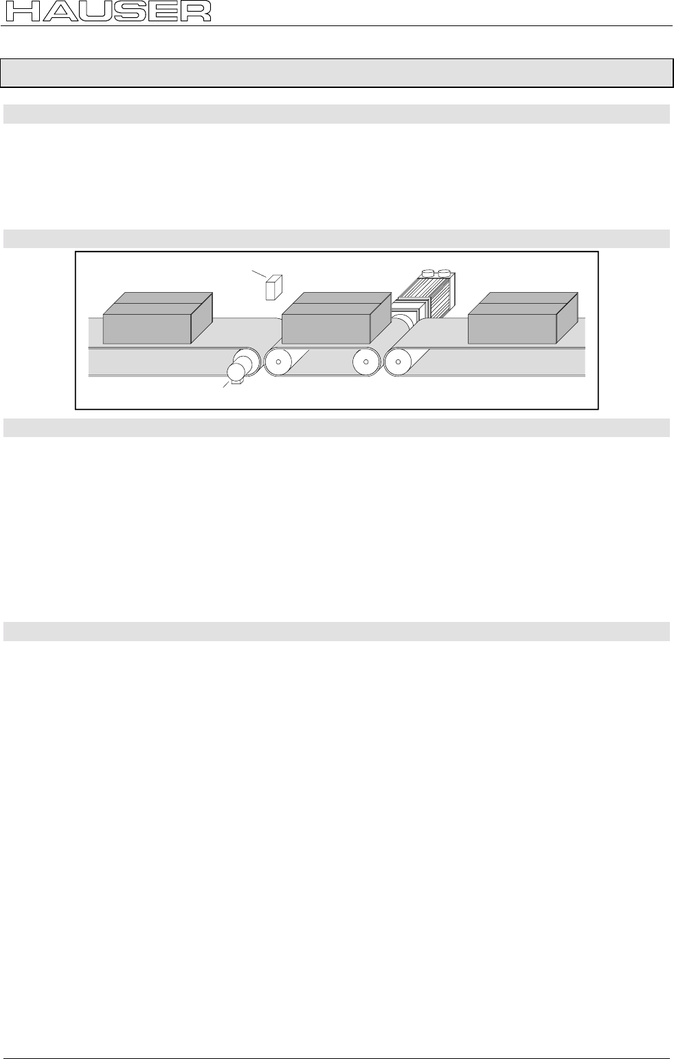
SPEED SYNC
233
11.1.5 SPEED SYNC
Application:
Cartons should be transferred from one conveyor belt (conveyor belt A), a belt operating at a very variable
belt speed, to another conveyor belt (conveyor belt C), a belt which has a constant belt speed. This task
should be performed using a transfer belt (conveyor belt B) installed between the two other belts. This belt
receives cartons from conveyor belt A and, when triggered by a pulse, passes them on to conveyor belt B. In
addition to this, when conveyor belt B is assigned, conveyor belt A should be blocked. Conveyor belt B is
activated using COMPAX.
Assignments:
light barrier
encoder
conveyor belt A conveyor belt B conveyor belt C
Function:
The first event after COMPAX has been started is the release of conveyor belt A. The system then waits until
the reflex light barrier (on I7) detects a carton (N003). Should a carton be received, the speed of conveyor
belt B is set to that of conveyor belt A (N004). This speed is recorded using an encoder on conveyor belt A
transmitting via the COMPAX encoder interface (channel 1). The positioning command (N005) now starts a
feed movement using the distance which is required to transfer the whole carton onto conveyor belt B. Since
the feed time is always the same as the speed of conveyor belt A, no errors occur due to slip between the
carton and one of the conveyor belts. Once the whole carton has been received, the system waits until I8
reports that the carton has been passed to conveyor belt C (N008). If, during this waiting time, another carton
arrives via conveyor belt A, this is blocked via O7. When the carton is passed on and conveyor belt A is
blocked, the speed of conveyor belt B is set to that of conveyor belt C (N010). The carton is transferred to
conveyor belt C at this constant speed using N011. Conveyor belt A is then released again (N002).
Programming:
Configuration:
Encoder input E2 option
P93 =+2 i.e. continuous operating mode
P98 =314 i.e. travel per axis per encoder revolution = 314 mm
P143 = 4096 i.e. encoder pulse number = 4096
Names of the inputs and outputs:
I7 receive carton 0 # no 1 # yes
I8 deposit carton 0 # no 1 # yes
O7 conveyor belt A 0 # block 1 # release
List of programs:
N001: ACCEL 200..............................................;sets the acceleration and braking ramps
Transfer carton:............................................ ;mark
N002: OUTPUT O7=1 ........................................ ;releases conveyor belt A
N003: IF I7=0 GOTO 3....................................... ;waits until carton is to be received
N004: SPEED SYNC.......................................... ;sets the speed to that on conveyor belt A
N005: POSR 360 ............................................... ;transfers the carton
N006: IF I7=0 GOTO 8....................................... ;queries whether carton is to be received
N007: OUTPUT O7=0 ........................................ ;blocks conveyor belt A
N008: IF I8=0 GOTO 6....................................... ;waits until carton is to be deposited
N009: OUTPUT O7=0 ........................................ ;blocks conveyor belt A
N010: SPEED 85 ............................................... ;sets the speed to that on conveyor belt C
N011: POSR 350 ............................................... ;deposits the carton
N012: GOTO transfers carton (2)....................... ;goes to data record N002
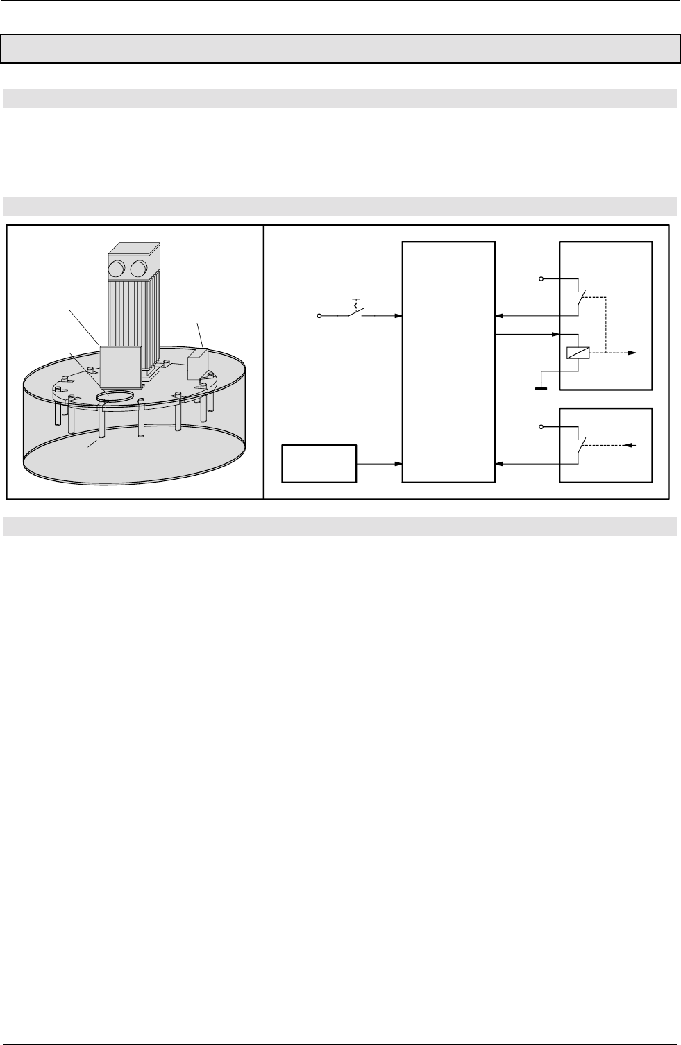
Application examples COMPAX-M/S
Speed control mode
234
11.1.6 Speed control mode
Application:
A centrifuge for manual operation should be operated by an operating mode switch. The centrifugal process
should either be run at a permanently set speed or the test tubes should be removed, one after another,
through the removal aperture. The shutter on the removal aperture must only be able to open when the
centrifuge is at a standstill.
Design and wiring up of the digital inputs and outputs:
light
barrier
opening
shutter
test tube
+24V
light
barrier
I10
I7
COMPAX
operating mode:
0 = remove
1 = centrifuge
I8
I9
O7
shutter
+24V
+24V
locking
Function:
The first event after COMPAX has been started is the setting of the accelerating and braking time 10s
(N001). A check is then run to find out whether the shutter is closed (N002). If it is not closed, the interlock is
opened (N003) and the system waits until the shutter is closed (N004). If the shutter is closed, the interlock is
also closed (N005). The interlock is checked for safety reasons (N006). The operating mode switch is then
queried (N007).
If this is set to "Removal", the speed is set to 0.1 % using N008. The system waits until the light barrier is
activated by a test tube (N010). When this occurs, the speed is set to 0 (N011) and the interlock is opened
(N012). The shutter can now be opened to insert or remove a test tube. COMPAX monitors the opening and
closing of the shutter (N013 / N014) to lock this again after the closing (N015 / N016) and to return to the
operating mode query. If "Removal" is still set, the centrifuge is turned further to the next test tube. (N009
ensures that once the speed has accelerated to 0.1% (N008), the system waits until the previous test tube
no longer activates the photoelectric barrier.)
If the operating mode switch is set in the "Centrifuge" position, the centrifuge is accelerated to 100% within
10s (N018). This speed is retained until the operating mode switch is set to "Removal" (N019 / N020). Then,
the centrifuge is decelerated to 0.1% (N008) and stops at the next test tube. The test tubes can then be
removed one after another.

Speed control mode
235
Programming:
Configuration:
P93 =+4 i.e. speed control operating mode
P94 =+2 i.e. smooth ramp shape
Names of the inputs and outputs:
I7 light barrier 0 # not activated 1 # activated
I8 shutter 0 # open 1 # closed
I9 interlock 0 # open 1 # closed
I10 operating mode 0 # remove 1 # centrifuge
O7 interlock 0 # closed 1 # open
List of programs:
N001: ACCEL 10 000......................................... ;sets the accelerating and braking ramps to 10s
N002: IF I8=1 GOTO locks (5) ........................... ;checks whether the shutter is closed
N003: OUTPUT O7=1 ........................................ ;opens interlock
N004: IF I8=0 GOTO 4....................................... ;waits until the shutter is closed
Lock:............................................................. ;mark
N005: OUTPUT O7=0 ........................................ ;closes interlock
N006: IF I9=0 GOTO 6....................................... ;checks whether interlock is closed
Operating mode query:
N007: IF I10=1 GOTO centrifuges (18).............. ;queries operating mode switch
Remove:....................................................... ;mark
N008: SPEED 0.1............................................... ;sets the speed to 0.1%
N009: WAIT 500.................................................;waits 500 ms
N010: IF I7=0 GOTO 10..................................... ;waits until the light barrier is activated
N011: SPEED 0 ................................................. ;sets the speed to 0
N012: OUTPUT O7=1 ........................................ ;opens interlock
N013: IF I8=1 GOTO 13..................................... ;waits until shutter is opened
N014: IF I8=0 GOTO 14..................................... ;waits until shutter is closed again
N015: OUTPUT O7=0 ........................................ ;closes interlock
N016: IF I9=0 GOTO 16..................................... ;checks whether interlock is closed
N017: GOTO operating mode query (7)............. ;goes to data record N007
Centrifuge:.................................................... ;mark
N018: SPEED 100.............................................. ;sets speed to 100%
N019: IF I10=0 GOTO removing (8)................... ;operating mode query
N020: GOTO 19 ................................................. ;goes to data record N019
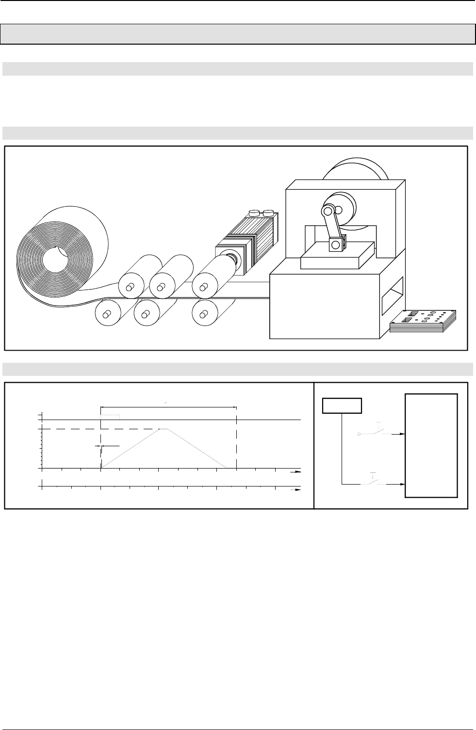
Application examples COMPAX-M/S
Fast start
236
11.1.7 Fast start
Application:
Material should be fed to an extender stamping machine which operates at a maximum speed of 150 rpm.
The material may only be supplied if the stamping tool is open and if the workpiece (already stamped) has
been thrown up. The material supply should be released or blocked via a switch.
Assignments:
Function:
I15
rotational
speed
j
t / ms
360°270°180°90°0°
4003002001000
1
0
100%
0
1.5ms
range within which positioning can be carried out
210° = 233ms initiator
I15
disable
enable
COMPAX
+24V I5
When the stamping machine runs at an operating speed of 150 strokes a minute, an operating cycle lasts
400 ms. The operating angle (at which the material can be fed) is 210°. 233 ms therefore remain for the feed
movement. To ensure that the necessary drive dynamics are kept within these limits, as much of this time as
possible must be used for the actual feed movement. This is why, the fast START is used here as it has a
response time of only 1.5 ms. The feed movement is triggered by the signal that the initiator (on the eccentric
axis) transfers via the release switch to COMPAX (I15) at an angle of ϕ = 90º.
Once the system has been switched on, COMPAX is started via a start pulse on I5. The values for the
accelerating and braking time are set in N001 and N002, as are those for the feed speed. The positioning
command in N003 is only performed, if a rising flank (from 0 to 1) is detected on I15 (fast START). The time
between the rising flank and the start of the feed movement is 1.5 ms. Data record N004 is used to return to
N003 which ensures that the next positioning command is prepared. This is then performed after a rising
flank on I15.

Implementing a torque controller
237
Programming:
Configuration:
P93 =+2 i.e. continuous operating mode
P94 =+1 i.e. linear ramp shape
P18 =+2 i.e. fast START activated
Names of the inputs and outputs:
I15 fast START a flank from 0 to 1 triggers the fast START
List of programs:
N001: ACCEL 100..............................................;sets the accelerating and braking ramps
N002: SPEED 100.............................................. ;sets the speed
Feed: ............................................................ ;mark
N003: POSR 225 ............................................... ;feed movement (triggered by fast START)
N004: GOTO feed (3)........................................ ;goes to data record N003
11.1.8 Implementing a torque controller
2 options are available:
Using speed control mode
You can attain a defined constant torque in speed control mode using the following setting.
♦
Set a high speed which cannot be reached.
♦
Define the desired torque using P16 in % of the nominal torque (max. 100%).
♦
Switch off errors E10 and E49 using P13=0.
COMPAX tries to reach the specified speed and increases the torque to the maximum permitted torque P16.
This value is maintained regardless of the load.
In position controller mode
♦
Specify a position which cannot be approached (which is beyond the load position).
♦
Define the desired torque using P16 in % of the nominal torque (max. 100%).
♦
Switch off errors E10 and E49 using P13=0.
♦
You can now use SPEED to also define the speed at which you can run up to the load (block position).
COMPAX tries to reach the specified postion and increases the torque in the load position to the maximum
permitted torque P16. This value is maintained regardless of the load.
Changing error response:
E49 can also be switched off individually:
E49 occurs when the current (and/or the torque) remains in the limitation for longer than P108.

Index COMPAX-M/S
238
12. Index
ABB – interface .................178
Absolute positioning ............96
Absolute value function
with standard resolver.......79
Absolute value resolver.......79
ACCEL ................................97
Acceleration and braking
time...................................97
Accessories and
options ...........................173
overview.........................174
Accuracy .............................65
Accuracy of calculations....115
Acknowledging error
messages .........................71
Activate position
adjustment ......................150
Activating mark
reference.........................100
Actual position...................207
Actual values Status
values .............................207
Addition .............................114
Advance acceleration
control P26......................130
Advance control
measures........................129
Advance power control
P70 .................................130
Advance reverse control....130
Advance speed control
P25 .................................130
Ambient conditions..............65
Analogue rpm
specification for
COMPAX 1000SL.............61
Analogue speed
specification (E7) ............186
Angle difference P161.........79
Application example
external data record
selection ........................227
fast start.........................236
mark-referenced
positioning......................229
speed control mode .......234
speed step profiling /
comparator switching
points .............................231
SPEED SYNC................233
Applications examples...226
Applications with
encoder...........................180
Arithmetic ..........................114
Assignment
absolute value sensor......59
EAM4/01 ........................180
HEDA...............................63
Incremental encoder ........60
Inputs/Outputs..................52
RS232 interface ...............59
X10 ..................................52
X11 ..................................56
X13 ................................186
X13 ..................................60
X14 ..................................63
X16 ..................................59
X17 ..................................55
X6 ....................................59
X8 ....................................52
Authorization of
commands in RS232.......165
Automatic "Position
reached" message ..........160
Avoiding harmonies...........131
Ballast resistance ....32, 38, 41
Ballast resistors .................193
Baud rate...........................160
BDF1/02 ............................187
BDF2/01 ............................200
Binary data transfer
using RS232 ...................166
Block check .......................161
Block structure of the
basic unit...........................68
Blocking and modifying
teach in functions P211...150
Blocking and modifying
the teach in functions
P211 ...............................164
Brake control .......................51
Braking delay.......................93
Braking operation ................64
Braking power
NMD.................................24
Braking power COMPAX
1000SL .............................41
Branching ..........................108
BREAK handling................111
BRM4 ................................193
BRM6 ................................193
BRM7 ................................193
Bus connection....................63
Bus data ............................207
Bus parameters
setting ..............................71
Bus systems ......................178
Bus termination .................180
Cable .................................206
Cable laying.........................13
Cable lengths.................... 206
Calculation errors ............. 115
Cam controller .................. 104
CAN-Bus........................... 178
CANopen .......................... 178
CE-compliant ...................... 13
Changes in speed within
a positioning process ..... 101
Command combinations... 101
Command variants ........... 109
Comparative operations.... 109
comparator switch points.. 101
COMPAX – CD..................... 9
COMPAX components..... 206
COMPAX 1000SL............... 40
COMPAX 25XXS
converting the front
plates .............................. 33
COMPAX 25XXS
specific technical data..... 32
COMPAX 25XXS
delivery status .................. 33
COMPAX 25XXS design
in series............................ 33
COMPAX 25XXS flat
design .............................. 33
COMPAX 25XXS unit
features ............................ 30
COMPAX 35XXS unit
features ............................ 26
COMPAX 45XXS/85XXS
connector assignment...... 39
COMPAX 45XXS/85XXS
unit characteristics ........... 35
COMPAX XX30 ................ 147
COMPAX XX50 ................ 147
COMPAX XX60 ................ 147
COMPAX XX70 ................ 147
COMPAX-25XXS
plan view ......................... 30
COMPAX-M / NMD
direct wall installation ....... 20
COMPAX-M / NMD
indirect wall installation .... 20
COMPAX-M system
network, mains module .... 18
COMPAX-M unit
features ............................ 17
Compensation of
switching delays............. 104
Components required ......... 14
Conditions for usage ....... 13
Conditions of warranty.......... 9
Configuration ...................... 72
Configuration data .............. 74
Configuration process......... 72

239
Configuration via PC ...........91
Configuration when
supplied ............................72
Connections to the drive......46
Connector and
connection assignment
COMPAX 25XXS.............30
Connector assignment
COMPAX 25XXS.............34
COMPAX-M.....................21
NMD ................................23
Connector assignment
COMPAX 1000SL.............42
Connector assignment
X13 for COMPAX
1000SL .............................61
Continuous mode ................74
point of real zero..............78
Control...............................147
Control voltage ............64, 207
CS31 .................................178
Current data record ...........207
Current nominal value .......208
Current requirement ............75
Currents ..............................64
Currents with linear
motor LXR.......................176
Curve memory...................113
D/A - Monitor (D1) ...............58
D/A monitor .........................56
D/A monitor (D1) ...............185
Damping P24 ....................128
Data format .......................160
Data security .........................6
Define encoder
interfaces ........................212
Delta mains .........................66
Diagnosis values ...............207
Digital inputs
Triggering functions .......150
Digital inputs and
outputs
Assignment....................138
Dimensions COMPAX
1000SL .............................43
Dimensions/installation
COMPAX 25XXS.............33
COMPAX-M.....................20
NMD ................................22
Direct command entry
conditions.......................162
Direction of rotation .............78
Division..............................114
Division remainder.............114
Drive status .......................208
Drive type ............................76
E10....................................225
E15....................................225
E49 ....................................237
E54 ....................................225
E76 ....................................171
E77 ....................................171
E78 ....................................171
EAM...................................188
EAM4/01............................180
Earthing ...............................13
Echo ..................................160
Effective motor load...135, 211
Effective unit load ......135, 211
Electronic transmission......147
EMC measures..................191
Emergency stop ..................44
Emergency stop
characteristics...................44
Emergency stop input on
COMPAX-M ......................45
Encoder .............................179
Encoder bus ......................182
Encoder cable ...................180
Encoder distributor ............180
Encoder input module........180
Encoder interface ..............179
Encoder interfaces for
COMPAX 1000SL.............61
Encoder module ................180
Encoder position................208
END...................................107
End sign ............................160
Entry buffer........................160
Equipment replacement.......12
Error diagnosis in the
mains module....................25
Error handling....................110
Error history.......................209
Error program ....................110
Error transmission .............161
EU guidelines ......................13
Executing commands ........160
External contact for
brake control .....................51
External control panel........187
External motors
conditions.........................75
External position
localization ......................136
Fan configuration
COMPAX-M .....................20
Fast start ...................168, 169
Final stage, engaging
and disengaging..............123
Find machine zero.............149
movement process...........81
Free assignment of
inputs and outputs...........143
Front plate operation ...........71
Function codes of
commands ......................159
Function of digital inputs... 148
Function of outputs ........... 153
Function overview............... 69
Function signs .................. 160
Fuse protection................... 64
Fuse protection
COMPAX 1000SL ............ 41
Fuse protection
COMPAX 2500S .............. 32
Fuse protection
COMPAX 3500M.............. 27
Fuse protection
COMPAX 45/8500S ......... 37
Fuse protection NMD.......... 23
GBK1 .................................. 59
General drive ...................... 77
Global assignment............ 114
GOSUB............................. 107
GOSUB EXT..................... 110
GOTO ......................... 99, 107
GOTO EXT ....................... 109
Hall sensor commutation .. 176
Hand-held terminal ........... 200
Hardware handshake ....... 160
HAUSER synchronous
motors ............................ 176
HEDA........................ 168, 183
HEDA address.................... 71
HEDA interface................. 185
HEDA parameters ............ 168
HEDA terminating
connector ......................... 63
HEDA transmission
errors.............................. 171
Higher level of stiffness .... 132
HJ motor ............................. 93
HLE data............................. 77
Housing .............................. 66
HPLA data .......................... 77
I/O assignment of
variants .......................... 147
I11..................................... 136
Idle display........................ 119
IF ERROR ........................ 110
IF ERROR GOSUB........... 110
IF I12=101-1 ..................... 108
IF I7=1 .............................. 108
IF query ............................ 108
IF STOP............................ 111
IFM identification .............. 208
Increments.......................... 74
Individual configuration
of synchronous motors
using Servo-Manager....... 91
Initial start-up ...................... 73
Initializing variables .......... 116
Initiator set ........................ 177

Index COMPAX-M/S
240
Initiators
connection plan................55
position ............................55
Initiators...............................55
Input connection..................54
Input I14 ............................100
Input I16 ....................100, 186
Input level............................54
Installation / dimensions
COMPAX
45XXS/85XXS .................36
Installation and
dimensions of
COMPAX 3500M ..............27
Installation arrangement
of the COMPAX-M
mains module ...................18
Interbus-S..........................178
Interfaces ..........................138
Interpreting and storing
commands ......................160
IPM....................................168
IT mains ..............................66
Lag error....................207, 225
Last error...........................207
Leakage current ..................66
LED display COMPAX
1000SL .............................40
LEDs ...................................10
Length code for cable..........47
Limit switch monitoring........89
Limit switch monitoring
without locking the
movement.........................89
Limit switch operation..........89
Limit torque P16 ................213
Limit values .......................213
Limitation functions............222
Limits status ......................208
Linear motor ......................176
Linear motor LXR ..............176
LXR ...................................176
Machine zero - initiator
(without resolver zero) ......88
Machine zero
comparison .......................83
Machine zero mode.............80
Mains...................................66
Mains module NMD10 /
NMD20 .............................22
Mains power......................207
Mains supply fuse
protection....................27, 64
Mark input .........................100
Mark-related positioning....100
Master output quantity.......169
Maximum feed length........100
Maximum mass ...................77
Maximum position P11 ........78
Maximum travel to mark ....100
Measuring error .135, 208, 211
Minimizing lag error ...........131
Minimum mass ....................77
Minimum position P12 .........78
Minimum travel to mark .....100
Modulo...............................114
Moment of inertia.................77
Monitoring..........................222
Monitoring functions ............65
Motor monitoring ...............222
Motor or final stage
temperature too high.......131
Motor output throttle ..........192
Motor throttle .....................206
Motor type ...........................75
Motor type plate...................92
Motors ...............................176
Mounting COMPAX
1000SL .............................43
Multiplication......................114
Multi-turn ...........................184
Negative command
acknowledgement...164, 225
NMD output power...............23
NMD20 internal ballast
resistance .........................24
Nominal current ...................92
Nominal currents .................64
Nominal currents with
linear motor LXR.............176
Nominal motor speed ..........93
Nominal torque ....................92
Normal mode.......................74
Number format ..................115
Number of teeth on
pinion ................................77
O5 toggles when speed.....120
Operating hours.................207
Operating mode...................74
Operating mode with two
end initiators......................89
Operators ..........................114
Optimization
control ............................131
Optimization display ..133, 207
Optimizing the controller....127
Option E7 ..........................186
Order .................................208
OUTPUT..............................98
Output buffer .....................160
Output connection ...............54
Output data..........................64
OUTPUT O0........................98
OUTPUT O0=... in
program ............................98
OUTPUT O12=1010............98
Output O16 ....................... 100
output O5.......................... 117
OUTPUT WORD .............. 143
Outputs
Load ................................ 54
Override input ..................... 97
P1 ....................................... 78
P100 ................................... 75
P11 ..................................... 78
P12 ..................................... 78
P14 ................................... 117
P143 ................................. 136
P144 ................................. 136
P151 ................................. 132
P17 ................................... 123
P18 ................................... 169
P182 ................................. 210
P184 ................................. 169
P188 ................................. 169
P206 ................................. 184
P213 ................................... 78
P214 ................................. 137
P215 ................................... 78
P217 ................................... 89
P219 ................................. 152
P223 ................................. 145
P224 ................................. 145
P227 ......................... 117, 119
P229 ................................. 119
P23 ................................... 127
P233 ................................. 133
P234 ................................. 133
P24 ................................... 128
P243 ................................. 168
P245 ................................. 145
P246 ................................. 145
P25 ................................... 130
P250 ................................. 168
P26 ................................... 130
P27 ................................... 128
P35 ................................... 100
P36 ................................... 136
P37 ................................... 100
P38 ................................... 100
P39 ................................... 100
P40-P49............................ 109
P50 ................................... 132
P69 ................................... 130
P70 ................................... 130
P71 ..................................... 58
P72 ..................................... 58
P73 ..................................... 58
P74 ..................................... 58
P75 ................................... 136
P80 ..................................... 76
P81 ..................................... 77
P81 - P85............................ 76
P82 ..................................... 77
P83 ..................................... 77

241
P88......................................77
P90......................................74
P92......................................77
P93......................................74
P94......................................75
P96....................................184
P98....................................136
Parameter assignments ....113
Parameter groups..............212
Parametrization of the
cam controller .................104
Parity .................................160
Part....................................208
Password ............................99
Password input....................70
Password protection............70
Peak current......................134
PLC data interface.............156
PLC sequential step
tracking ...........................122
Plug and connection
assignment
COMPAX 35XXM ............26
COMPAX
45XXS/85XXS .................35
POSA ..................................96
POSA HOME ..............96, 162
Position monitoring............117
Position of machine zero.....83
POSR ..........................96, 100
POSR OUTPUT ................103
POSR SPEED...................101
Potentiometer
connection ........................56
Power ..................................64
Power dissipation ................65
Power filter ........................191
Power on .............................73
Power on with motor
switched off.......................72
Power with linear motor
LXR.................................176
Priority ...............................110
Process coupling...............168
Process interfaces
Configuration options
for COMPAX 1000SL........61
Process interfaces for
unit variants ......................60
Process velocity ..................97
Profibus .............................178
Program control
data record selection .....110
Data record selection109, 110
WAIT START.................109
Program jump....................107
Program loop.....................108
Proper use.............................8
Pulse current .......................93
Pulse current time ...............93
Querying status values
via the front plate ..............71
Ramp shape ........................75
linear ................................76
quadratic ..........................76
smooth .............................76
Ramp time .........................102
Read and write program
sets and parameters
via RS232 .......................163
Read the status values
via RS232 .......................163
Readiness ...........................44
Ready contact .....................45
Real zero .............................81
Reduction of dynamic
lag error ..........................130
Reference systems
example ...........................80
Relative positioning .............96
REPEAT ............................108
Repeat counter..................207
Resolver / SinCos
assignment........................46
Resolver type ......................93
RETURN ...........................107
Return jump to main
program ..........................107
Round table control ...........147
RS232 ...............................160
Example in Quick-Basic .161
RS232 data .......................207
RS232 interface
parameters......................160
RS485 ...............................178
S1 ......................................183
S1/2/3 assignment X12 .......46
S13 ....................................133
S14 ....................................133
S15 ....................................210
S16 ....................................209
S17 ....................................209
S18 ....................................209
S2 ......................................184
S3 ......................................176
Safe working practices ..........8
Safety chain.........................44
Safety chain and
emergency stop
functions ...........................44
Safety instructions..............8
Saturation characteristic
curve .................................93
Screened connection of
motor cable
COMPAX 25XXS .............31
COMPAX-M .....................19
Sensor position................. 207
Sequential step tracking ... 122
Service D/A monitor.......... 124
Service D/A monitor (D1).... 56
Servo-Manager................. 200
Setting multiple digital
outputs ............................. 98
Setting/resetting outputs..... 98
Setting/resetting outputs
within positioning............ 103
SHIFT ............................... 148
SHIFT ............................... 148
Short circuit monitoring..... 222
Signal procedure during
status query via PLC
interface ......................... 159
SinCos .............................. 183
Slave input quantities ....... 169
Software date ................... 208
Software handshake......... 160
Software handshake......... 161
Software version....... 1, 7, 208
Specifying point of real
zero P1 (RZ)..................... 78
Specifying software end
limits................................. 78
Specifying the limit
switch position P216 ........ 89
Speed ............................... 208
SPEED ............................... 97
Speed control mode ........... 74
direction of rotation.......... 97
Speed control mode,
special features.............. 120
Speed monitor .................. 132
Speed monitoring in
speed control mode........ 120
Speed step profile............. 102
Speed step profiles........... 101
SPEED SYNC .................... 99
SSK1 .................................. 59
SSK14 ................................ 63
SSK15 ................................ 63
SSK6 ................................ 188
SSK7 ................................ 180
Standard commands .......... 96
Standard delivery................ 66
Standard parameters........ 212
Start-up
flow chart......................... 11
Status bits......................... 208
Status bits 1...................... 207
Status monitor .......... 207, 210
Status values .................... 207
Step direction input for
COMPAX 1000SL ............ 61
Stiffness P23 .................... 127
STOP................................ 149
Stop bit ............................. 160
STOP handling ................. 111

Index COMPAX-M/S
242
Stop program ....................112
Sub-program .....................107
Subtraction ........................114
Supply status.......................10
Supported resolvers ............64
Switch off.............................98
Switch off drive unit .............98
Switch status .....................208
Switching delays ...............104
Switching off........................72
Switch-on status ...............10
Synchronization errors ......171
Synchronizing to
external velocity................99
Synchronous cycle
control.............................147
Synchronous STOP
using I13 .........................151
System concept.................173
Table of contents................2
Target position ..................207
Teach in real zero..............149
TEACH position.................164
Technical data.....................64
Technical data / power
features
NMD ................................23
Temperature......................207
Terminal boxes....................46
Terminal module................188
Test / control .......................56
TN mains.............................66
Toggling when position
is reached .......................117
Tooth pitch ..........................77
Torque...............................207
Torque converter.......226, 237
Transmission errors...........171
Transmitting control
instructions via RS232 ....164
Travel cycle .......................207
Travel per motor
revolution ..........................77
Type plate .............................7
Unit....................................208
increments .......................74
Unit......................................74
Unit assignment ....................7
Unit designation ................208
Unit designations...............208
Unit family .........................208
Unit monitoring ..................222
Unit technology ...................15
Unit wiring COMPAX
1000SL .............................41
V0-V49 ..............................109
Variable voltage ................124
Variables ...........................114
Variables V51 ... V70.........114
Velocity..............................207
Velocity specification,
external .............................99
Version ..............................208
Vibrating at higher
frequencies .....................131
Voltage ..............................124
VP parameter, modifying
OnLine ............................212
WAIT .................................107
WAIT START.....................109
Waiting time.......................107
Weights ...............................66
Whole number division ......114
Wiring up mains power /
control voltage
COMPAX 25XXS .............32
COMPAX 45/85S.............37
COMPAX-M .....................19
Wiring up motor
COMPAX 25XXS .............31
COMPAX 45/85S.............37
Wiring up the motor
COMPAX-M .....................19
Wiring up the system
network .............................18
Word length .......................160
X12 ......................................46
Zero point shifting................83
