Particle ARGN Argon User Manual Argon
Particle Industries, Inc. Argon Argon
UserManual.wiki
>
Particle
>
ARGN User Manual
User Manual
Navigation menu
Upload a User Manual
Namespaces
Wiki Guide
HTML
PDF
Info
Views
User Manual
Discussion / Help
Navigation
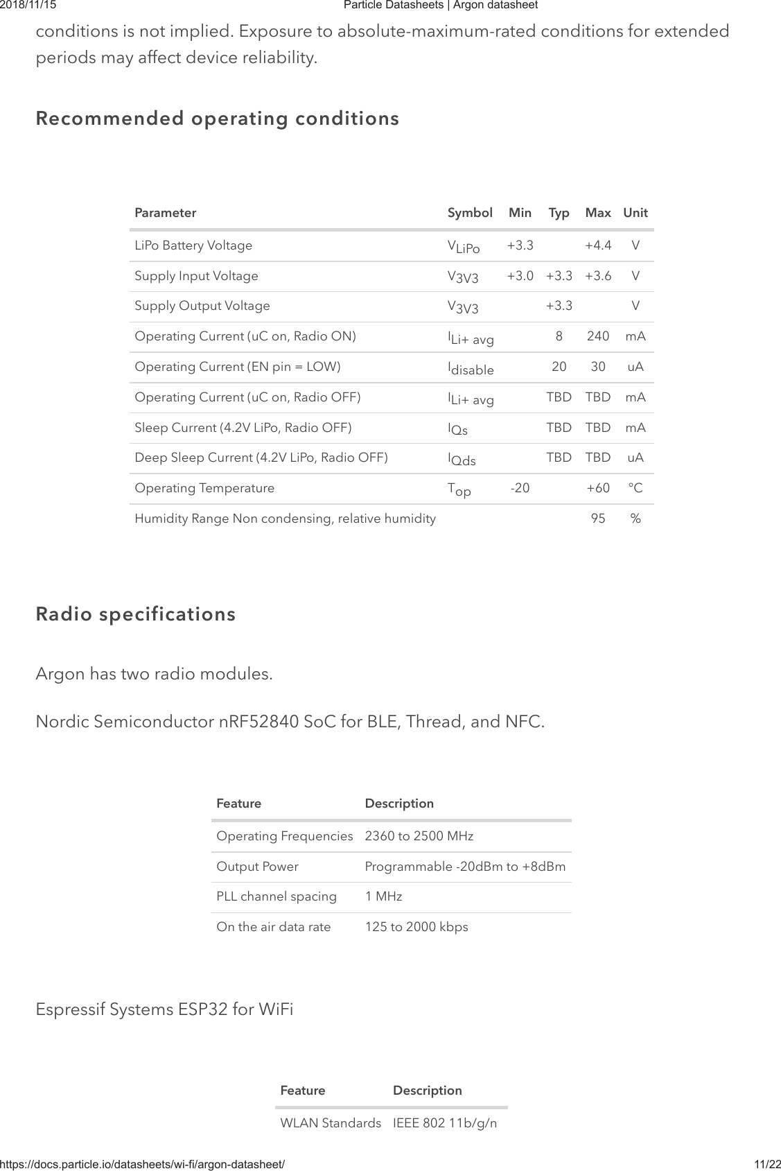
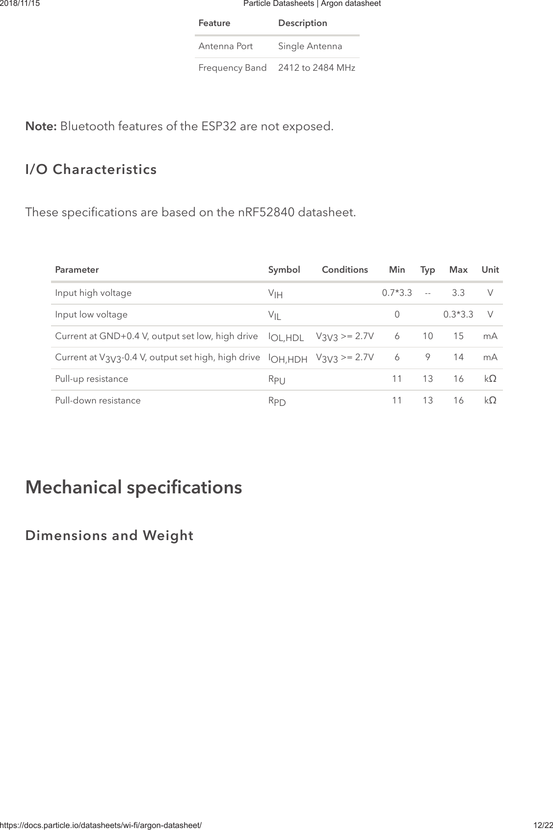
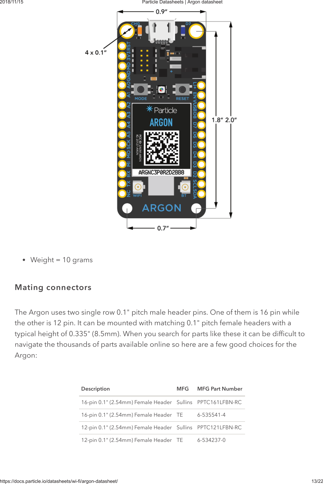
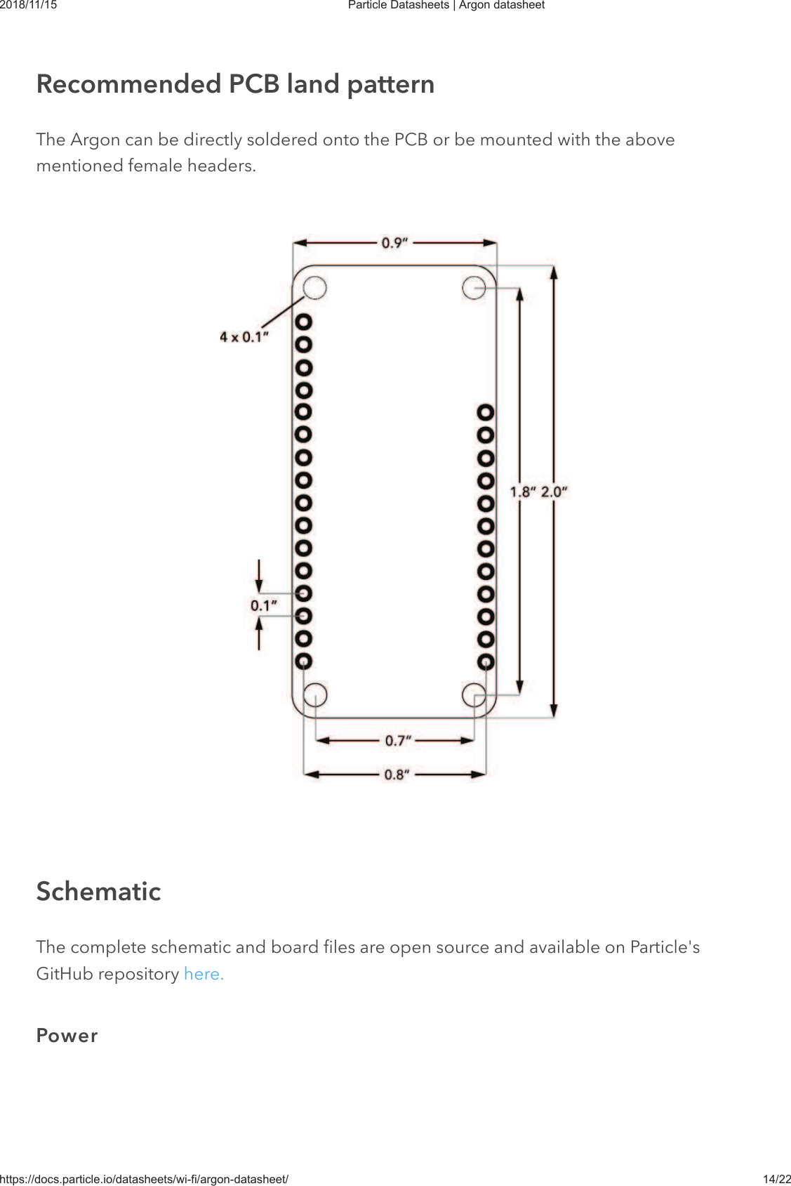
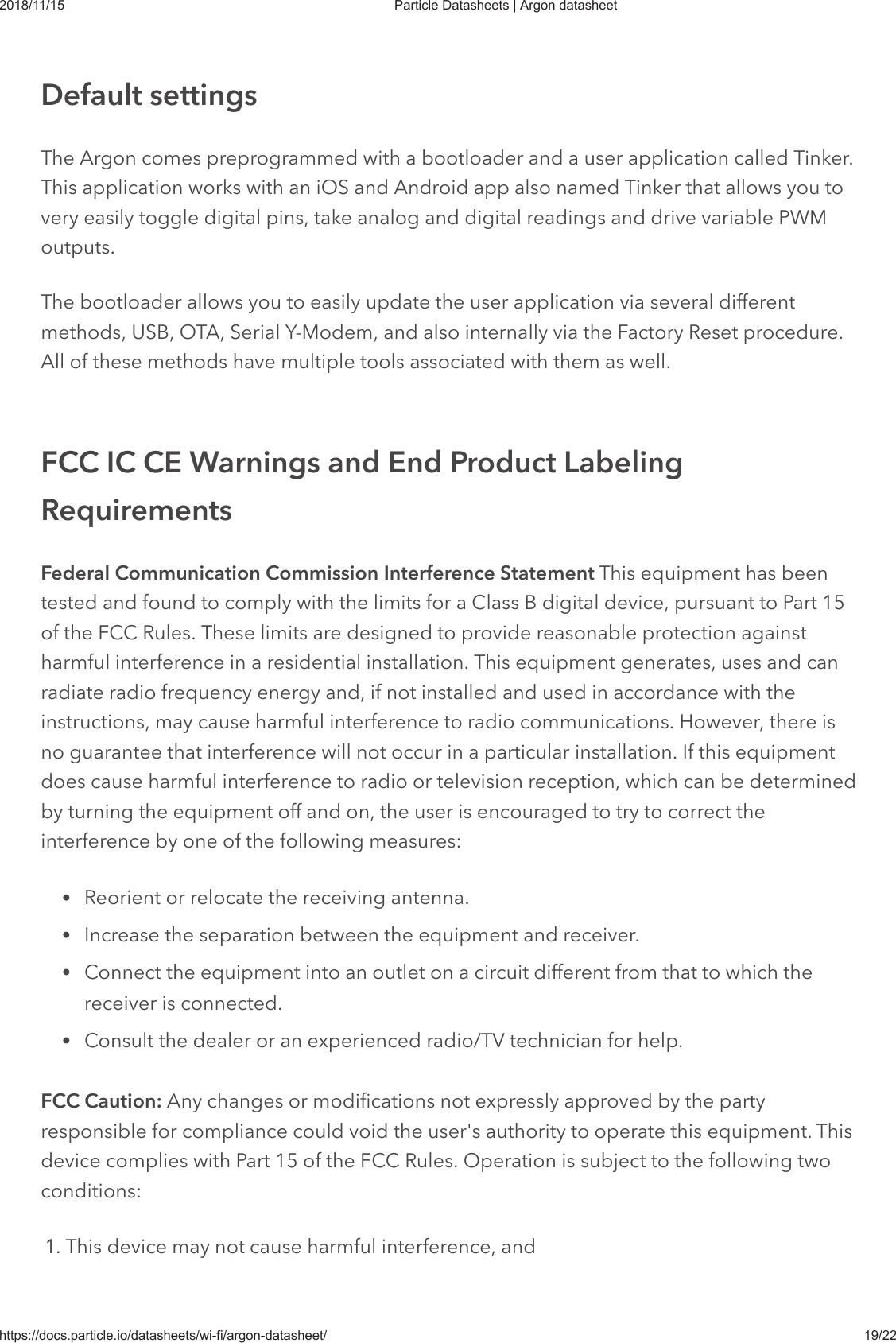
![2018/11/15 Particle Datasheets | Argon datasheethttps://docs.particle.io/datasheets/wi-fi/argon-datasheet/ 10/22Pin DescriptionD2-D8 These are generic GPIO pins. D2-D8 are PWM-able.A0-A5 These are analog input pins that can also act as standard digital GPIO. A0-A5 are PWM-able.For a detailed explanation of different color codes of the RGB system LED, please take alook here.State DescriptionON Charging in progressOFF Charging completeParameter Symbol Min Typ Max UnitSupply Input Voltage V +6.2 VBattery Input Voltage V +6.5 VSupply Output Current I 1000 mAStorage Temperature T -30 +75 °CESD Susceptibility HBM (Human Body Mode) V 2 kV Stresses beyond those listed under absolute maximum ratings may cause permanentdamage to the device. These are stress ratings only, and functional operation of the deviceat these or any other conditions beyond those indicated under recommended operatingLED statusSystem RGB LEDCharge status LEDTechnical specificationsAbsolute maximum ratings [1]IN-MAXLiPo3V3-MAX-LstgESD[1]](https://usermanual.wiki/Particle/ARGN/User-Guide-4196499-Page-10.png)