User Manual
2018/11/15 Particle Datasheets | Xenon datasheet
https://docs.particle.io/datasheets/mesh/xenon-datasheet/ 1/22
DOWNLOAD PDF
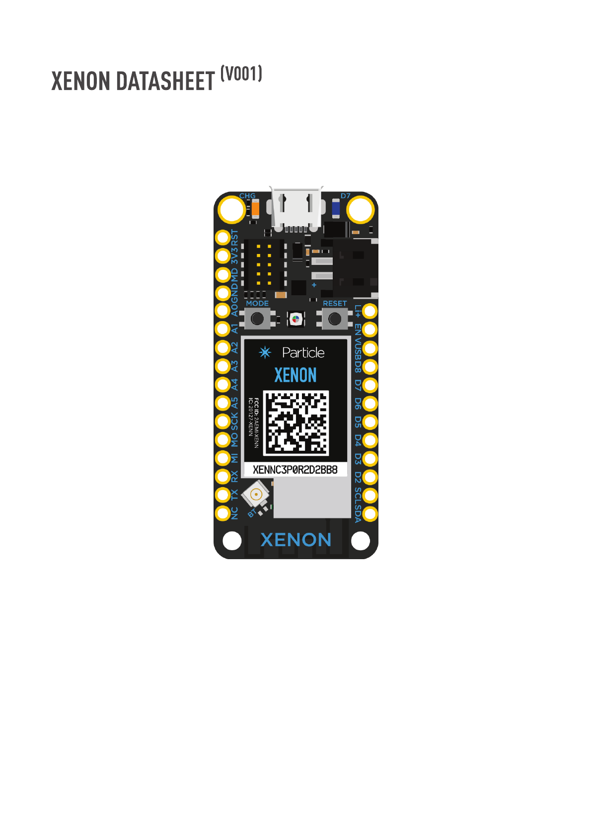
The Xenon is a low cost mesh-enabled development board that can act as either an
endpoint or repeater within a Particle Mesh network.
The Xenon is mesh only and designed to function as the endpoint of your IoT network. It is
based on the Nordic nRF52840 and has built-in battery charging circuitry so it’s easy to
Functional description
Overview
2018/11/15 Particle Datasheets | Xenon datasheet
https://docs.particle.io/datasheets/mesh/xenon-datasheet/ 2/22
connect a Li-Po and deploy your local network in minutes.
The Xenon is best for connecting sensors, motors, pumps, valves, and points of data-
interest. Pair it with an Argon or Boron gateway to get all that great data into the Device
Cloud.
Nordic Semiconductor nRF52840 SoC
ARM Cortex-M4F 32-bit processor @ 64MHz
1MB flash, 256KB RAM
IEEE 802.15.4-2006: 250 Kbps
Bluetooth 5: 2 Mbps, 1 Mbps, 500 Kbps, 125 Kbps
Supports DSP instructions, HW accelerated Floating Point Unit (FPU) calculations
ARM TrustZone CryptoCell-310 Cryptographic and security module
Up to +8 dBm TX power (down to -20 dBm in 4 dB steps)
NFC-A tag
On-board additional 4MB SPI flash
20 mixed signal GPIO (6 x Analog, 8 x PWM), UART, I2C, SPI
Micro USB 2.0 full speed (12 Mbps)
Integrated Li-Po charging and battery connector
JTAG (SWD) Connector
RGB status LED
Reset and Mode buttons
On-board PCB antenna
u.FL connector for external antenna
Meets the Adafruit Feather specification in dimensions and pinout
FCC, CE and IC certified
RoHS compliant (lead-free)
Features
Interfaces
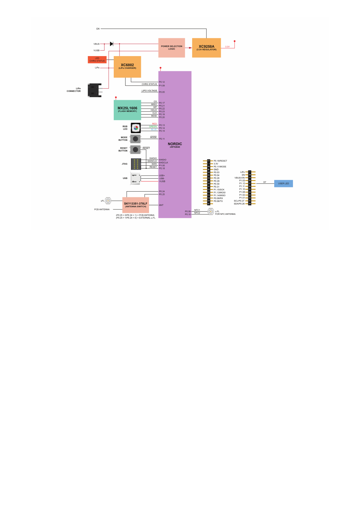
Block diagram
2018/11/15 Particle Datasheets | Xenon datasheet
https://docs.particle.io/datasheets/mesh/xenon-datasheet/ 3/22
The USB port is the easiest way to power up the Xenon. Please make sure that the USB
port is able to provided at least 500mA. Power from the USB is regulated down to 3.3V by
the on board Torex XC9258A step-down regulator.
The pin is internally connected to the VBUS of the USB port. The typical output should be
around 4.5 to 5 VDC when the device is plugged into the USB port and 0 when not
connected to a USB source. You can use this pin to power peripherals that operate at such
voltages. Do not exceed the current rating of the USB port, which is nominally rated to
500mA. This pin is also protected with an internal fuse rated at 1000mA.
Power
USB PORT
VUSB PIN
LiPo
2018/11/15 Particle Datasheets | Xenon datasheet
https://docs.particle.io/datasheets/mesh/xenon-datasheet/ 4/22
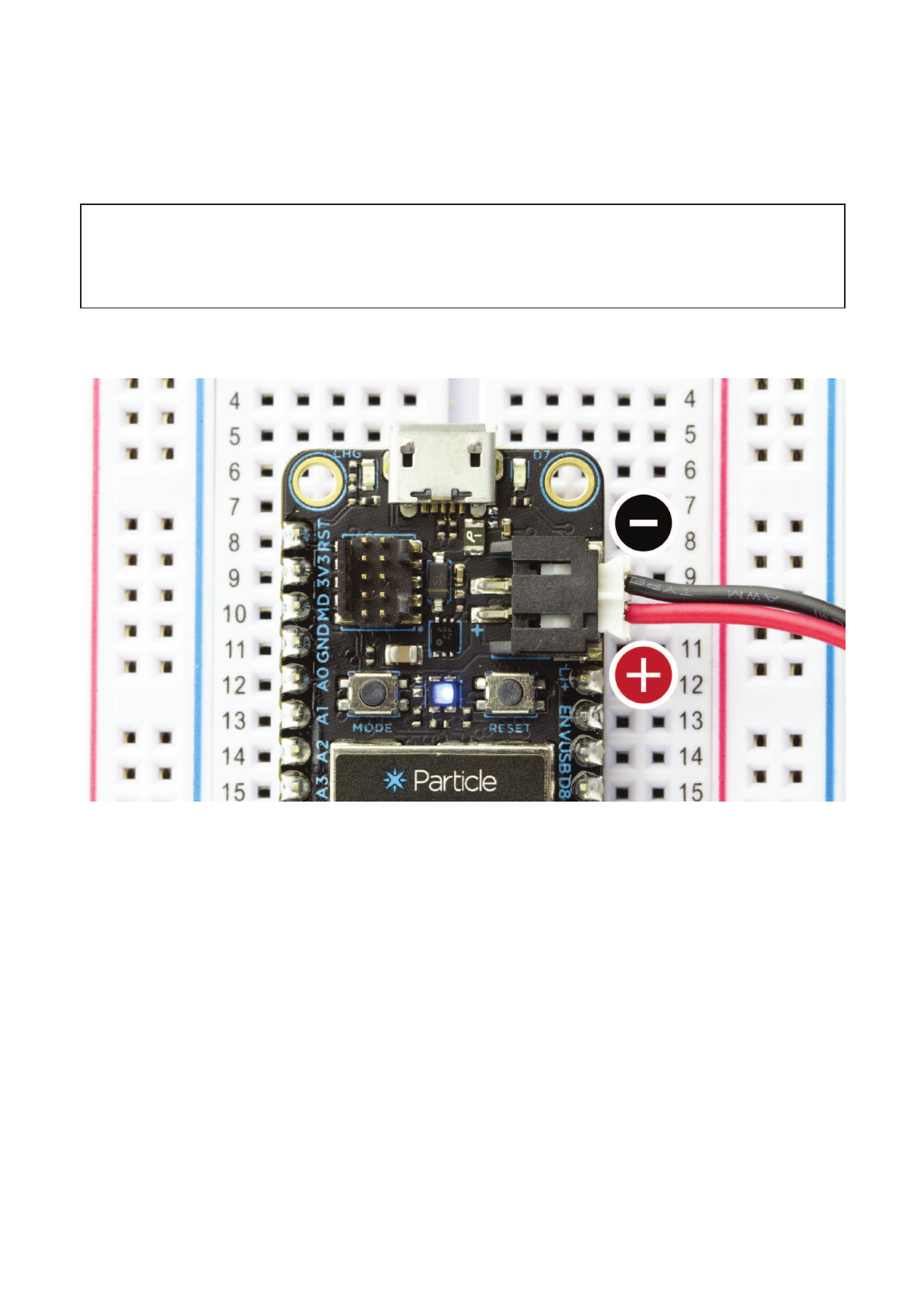
If you want to make your projects truly wireless, you can power the device with a single
cell LiPo/Lithium Ion (3.7V). The Xenon has an on board LiPo charger that will charge and
power the device when USB source is plugged in, or power the device from the LiPo alone
in the absence of the USB.
NOTE: Please pay attention to the polarity of the LiPo connector. Not all LiPo
batteries follow the same polarity convention!
This pin is internally connected to the positive terminal of the LiPo connector. You can
connect a single cell LiPo/Lithium Ion or a DC supply source to this pin for powering the
Xenon. Remember that the input voltage range on this pin is 3.6 to 4.2 VDC.
This pin is the output of the on board 3.3V step-down switching regulator (Torex
XC9258A). The regulator is rated at 1000mA max. When using this pin to power other
devices or peripherals remember to budget in the current requirement of the Xenon first.
This pin can also be used to power the Xenon in absence of the USB or LiPo power. When
Li+ PIN
3V3 PIN
2018/11/15 Particle Datasheets | Xenon datasheet
https://docs.particle.io/datasheets/mesh/xenon-datasheet/ 5/22
powering over this pin, please connect the ENABLE pin to GND so that the on board
regulator is disabled.
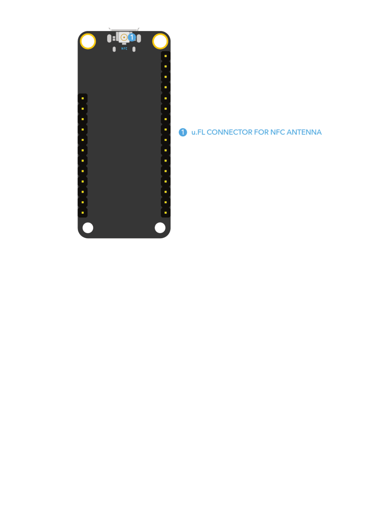
There are two options for the Mesh antenna on the Xenon. It comes with an on-board PCB
antenna which is selected by default in the device OS and a u.FL connector if you wish to
connect an external antenna. If you wish to use the external antenna, you'll need to issue
an appropriate command in the firmware.
The following antenna is optional, as the Xenon comes with an on-board PCB antenna.
Particle Device Frequency Antenna Type Manufacturer MFG. Part # Gain
Xenon 2400-2500 MHz PCB Antenna Particle ANT-FLXV2 2.0dBi peak
Peripheral Type Qty Input(I) / Output(O)
Digital 20 I/O
Analog (ADC) 6 I
UART 1 I/O
SPI 1 I/O
I2C 2 I/O
USB 1 I/O
PWM 8 O
Note: All GPIOs are only rated at 3.3VDC max.
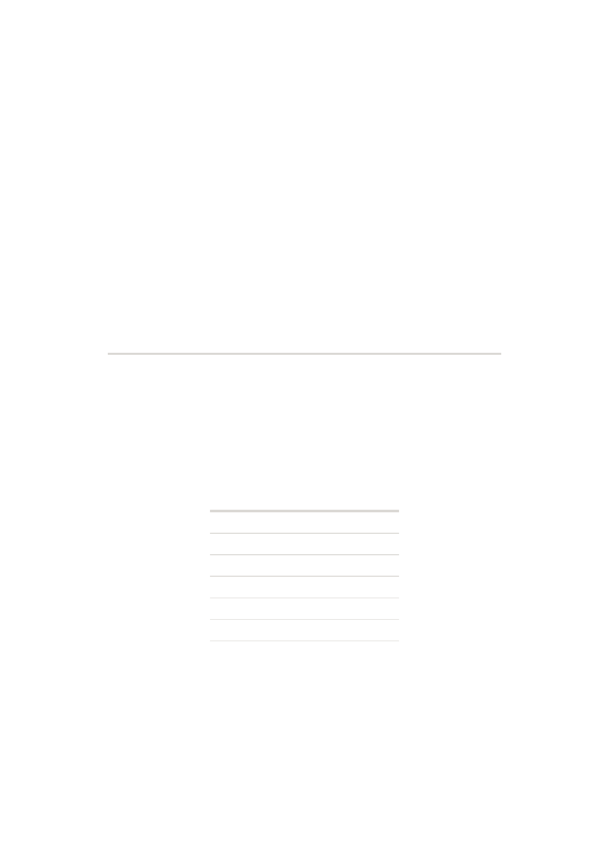
The Xenon has a dedicated 10 pin debug connector that exposes the SWD interface of
the nRF5280. This interface can be used to debug your code or reprogram your Xenon
Antenna
FCC approved antenna
Peripherals and GPIO
SWD
2018/11/15 Particle Datasheets | Xenon datasheet
https://docs.particle.io/datasheets/mesh/xenon-datasheet/ 6/22
bootloader, device OS, or the user firmware using any standard SWD tools including our
Mesh Debugger.
Bootloader (48KB, @0xF4000)
User Application (128KB, @0xD4000)
System (656KB, @0x30000)
SoftDevice (192KB)
OTA (1500KB, @0x00289000)
Reserved (420KB, @0x00220000)
FAC (128KB, @0x00200000)
LittleFS (2M, @0x00000000)
Memory map
nRF52840 Flash Layout Overview
External SPI Flash Layout Overview (DFU offset: 0x80000000)
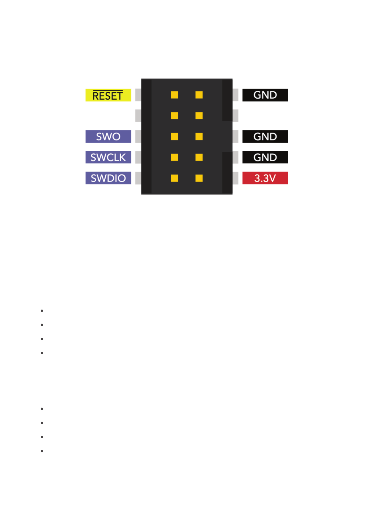
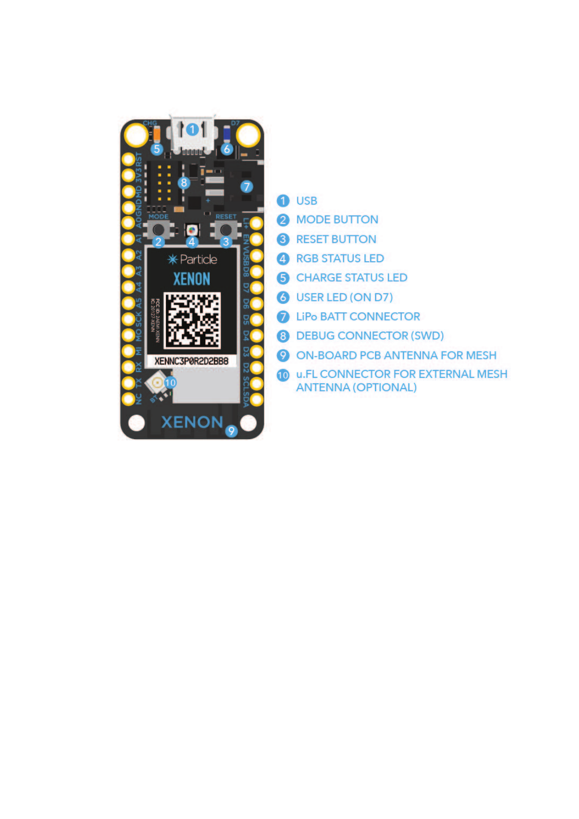
Pins and button definitions
2018/11/15 Particle Datasheets | Xenon datasheet
https://docs.particle.io/datasheets/mesh/xenon-datasheet/ 7/22
Pin markings
2018/11/15 Particle Datasheets | Xenon datasheet
https://docs.particle.io/datasheets/mesh/xenon-datasheet/ 8/22
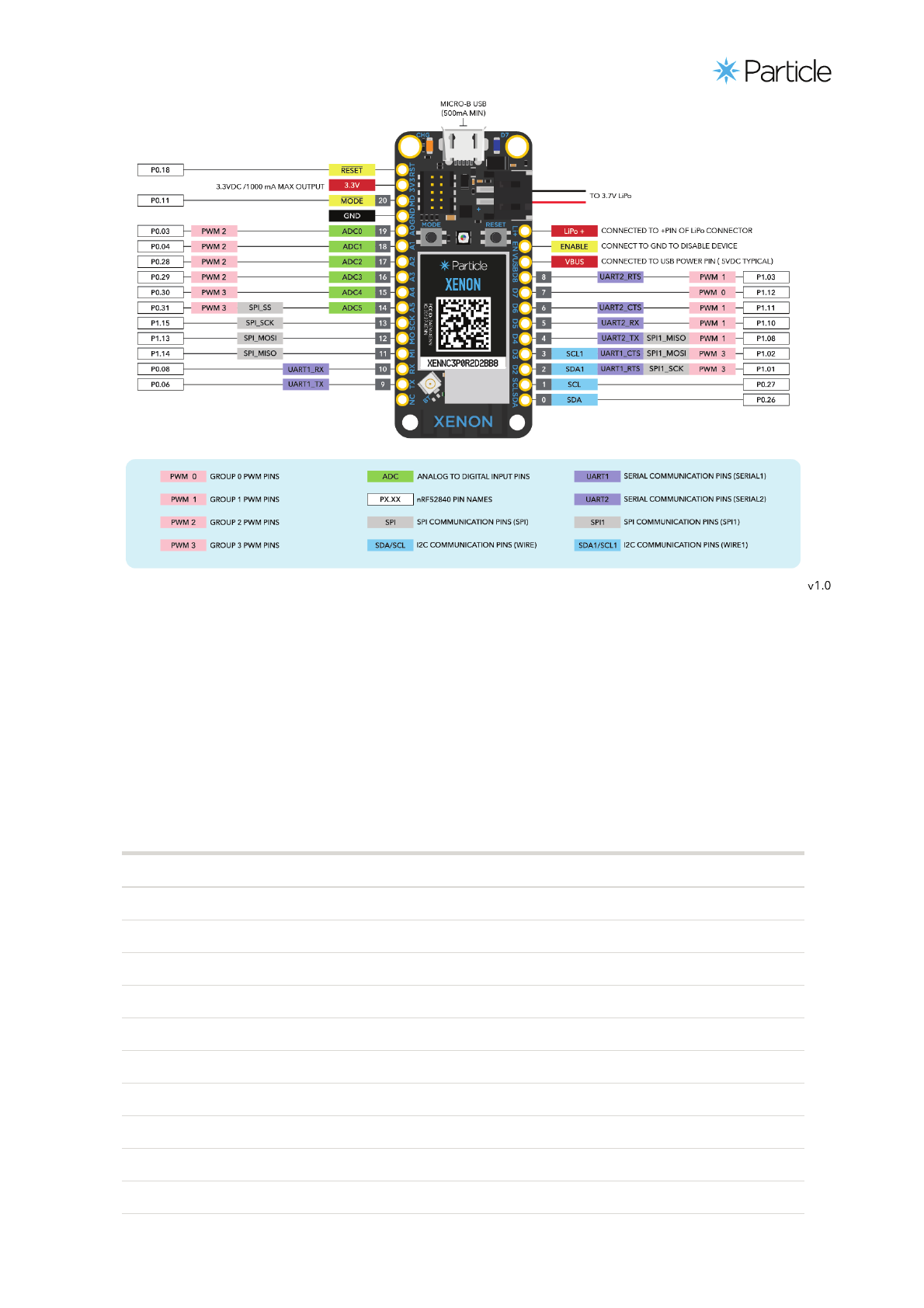
Pinout diagram
2018/11/15 Particle Datasheets | Xenon datasheet
https://docs.particle.io/datasheets/mesh/xenon-datasheet/ 9/22
You can download a high resolution PDF version of the pin out here.
Pin Description
Li+ This pin is internally connected to the positive terminal of the LiPo battery connector.
VUSB This pin is internally connected to the USB (+ve) supply.
3V3 This pin is the output of the on-board 3.3V regulator.
GND System ground pin.
EN Device enable pin is internally pulled-up. To disable the device, connect this pin to GND.
RST Active-low system reset input. This pin is internally pulled-up.
MD This pin is internally connected to the MODE button. The MODE function is active-low.
RX Primarily used as UART RX, but can also be used as a digital GPIO.
TX Primarily used as UART TX, but can also be used as a digital GPIO.
SDA Primarily used as data pin for I2C, but can also be used as a digital GPIO.
SCL Primarily used as clock pin for I2C, but can also be used as a digital GPIO.
MO,MI,SCK These are the SPI interface pins, but can also be used as a digital GPIO.
Pin description

2018/11/15 Particle Datasheets | Xenon datasheet
https://docs.particle.io/datasheets/mesh/xenon-datasheet/ 10/22
Pin Description
D2-D8 These are generic GPIO pins. D2-D8 are PWM-able.
A0-A5 These are analog input pins that can also act as standard digital GPIO. A0-A5 are PWM-able.
For a detailed explanation of different color codes of the RGB system LED, please take a
look here.
State Description
ON Charging in progress
OFF Charging complete
Parameter Symbol Min Typ Max Unit
Supply Input Voltage V +6.2 V
Battery Input Voltage V +6.5 V
Supply Output Current I 1000 mA
Storage Temperature T -30 +75 °C
ESD Susceptibility HBM (Human Body Mode) V 2 kV
Stresses beyond those listed under absolute maximum ratings may cause permanent
damage to the device. These are stress ratings only, and functional operation of the device
at these or any other conditions beyond those indicated under recommended operating
LED status
System RGB LED
Charge status LED
Technical specifications
Absolute maximum ratings [1]
IN-MAX
LiPo
3V3-MAX-L
stg
ESD
[1]
2018/11/15 Particle Datasheets | Xenon datasheet
https://docs.particle.io/datasheets/mesh/xenon-datasheet/ 11/22
conditions is not implied. Exposure to absolute-maximum-rated conditions for extended
periods may affect device reliability.
Parameter Symbol Min Typ Max Unit
LiPo Battery Voltage V +3.3 +4.4 V
Supply Input Voltage V +3.0 +3.3 +3.6 V
Supply Output Voltage V +3.3 V
Operating Current (uC on, Radio ON) I 6 20 mA
Operating Current (uC on, Radio OFF) I TBD TBD mA
Operating Current (EN pin = LOW) I 20 30 uA
Sleep Current (4.2V LiPo, Radio OFF) I TBD TBD mA
Deep Sleep Current (4.2V LiPo, Radio OFF) I TBD TBD uA
Operating Temperature T -20 +60 °C
Humidity Range Non condensing, relative humidity 95 %
Xenon uses the Nordic Semiconductor nRF52840 SoC as the main controller and the
mesh radio.
Feature Description
Operating Frequencies 2360 to 2500 MHz
Output Power Programmable -20dBm to +8dBm
PLL channel spacing 1 MHz
On the air data rate 125 to 2000 kbps
These specifications are based on the nRF52840 datasheet.
Recommended operating conditions
LiPo
3V3
3V3
Li+ avg
Li+ avg
disable
Qs
Qds
op
Radio specifications
I/O Characteristics
2018/11/15 Particle Datasheets | Xenon datasheet
https://docs.particle.io/datasheets/mesh/xenon-datasheet/ 12/22
Parameter Symbol Conditions Min Typ Max UnitParameter Symbol Conditions Min Typ Max Unit
Input high voltage V 0.7*3.3 -- 3.3 V
Input low voltage V 0 0.3*3.3 V
Current at GND+0.4 V, output set low, high drive I V >= 2.7V 6 10 15 mA
Current at V -0.4 V, output set high, high drive I V >= 2.7V 6 9 14 mA
Pull-up resistance R 11 13 16 kœ
Pull-down resistance R 11 13 16 kœ
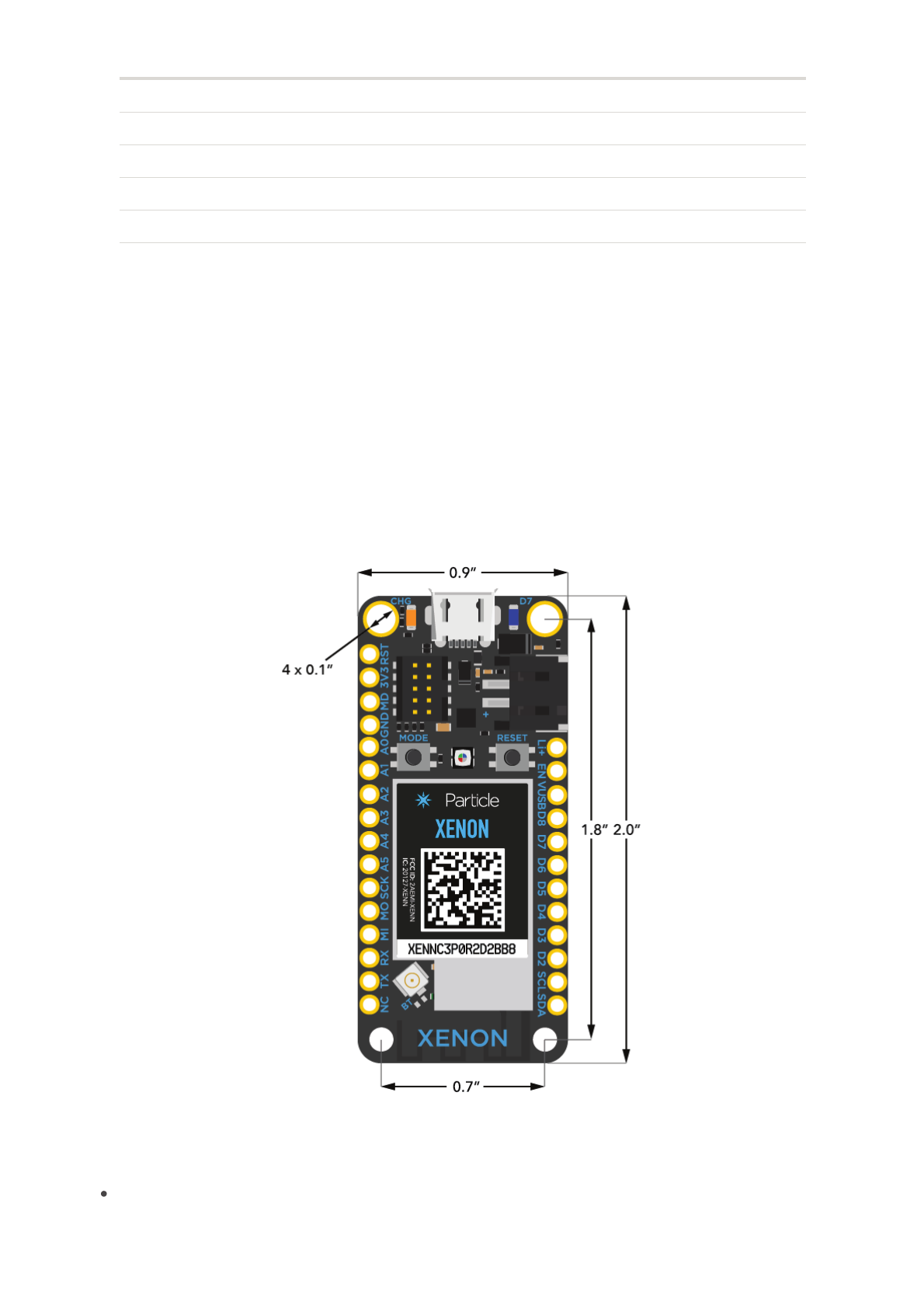
Weight = 10 grams
IH
IL
OL,HDL 3V3
3V3 OH,HDH 3V3
PU
PD
Mechanical specifications
Dimensions and Weight

2018/11/15 Particle Datasheets | Xenon datasheet
https://docs.particle.io/datasheets/mesh/xenon-datasheet/ 13/22
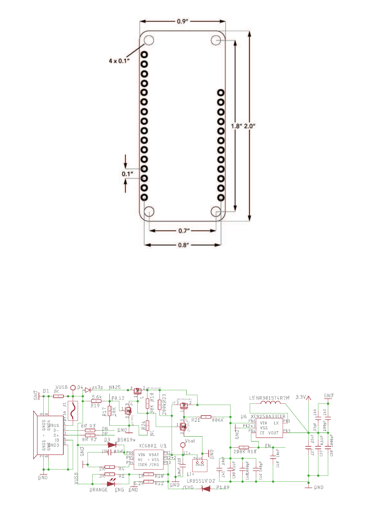
The Xenon uses two single row 0.1" pitch male header pins. One of them is 16 pin while
the other is 12 pin. It can be mounted with matching 0.1" pitch female headers with a
typical height of 0.335" (8.5mm). When you search for parts like these it can be difficult to
navigate the thousands of parts available online so here are a few good choices for the
Xenon:
Description MFG MFG Part Number
16-pin 0.1" (2.54mm) Female Header Sullins PPTC161LFBN-RC
16-pin 0.1" (2.54mm) Female Header TE 6-535541-4
12-pin 0.1" (2.54mm) Female Header Sullins PPTC121LFBN-RC
12-pin 0.1" (2.54mm) Female Header TE 6-534237-0
The Xenon can be directly soldered onto the PCB or be mounted with the above
mentioned female headers.
Mating connectors
Recommended PCB land pattern
2018/11/15 Particle Datasheets | Xenon datasheet
https://docs.particle.io/datasheets/mesh/xenon-datasheet/ 14/22
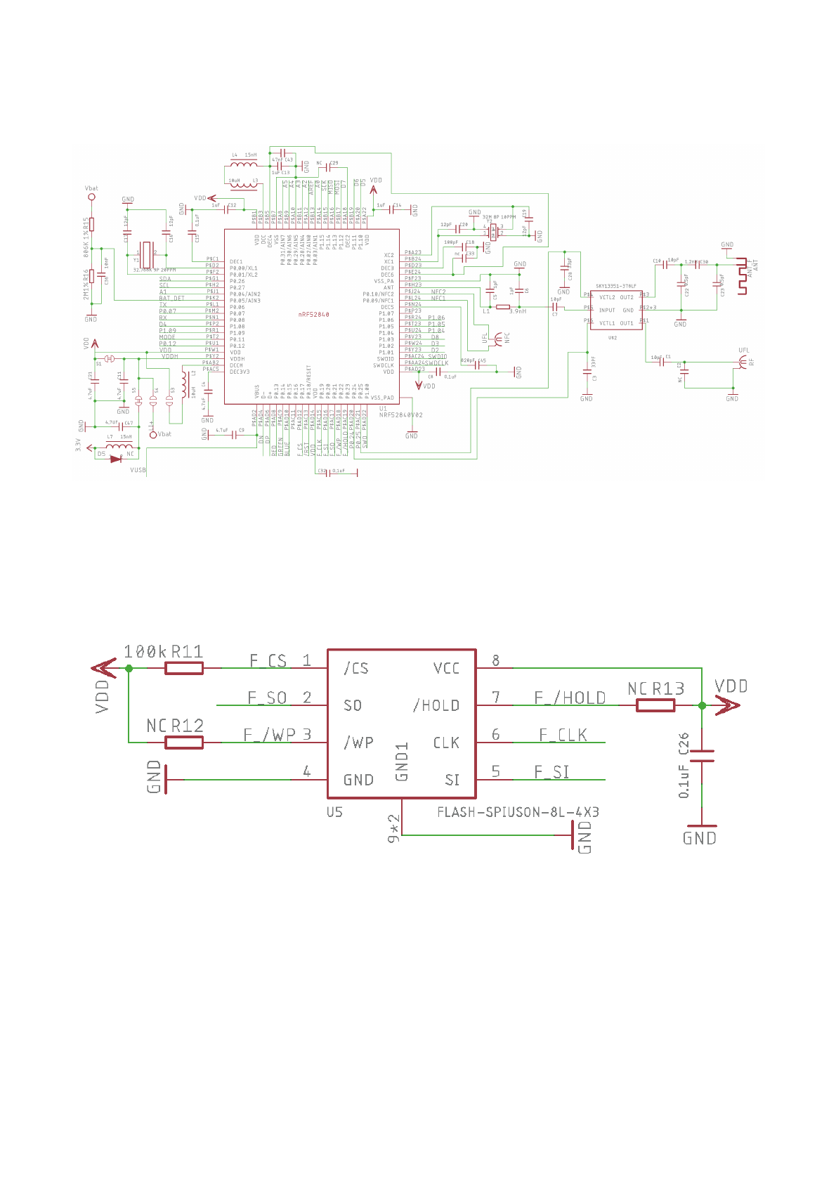
The complete schematic and board files are open source and available on Particle's
GitHub repository here.
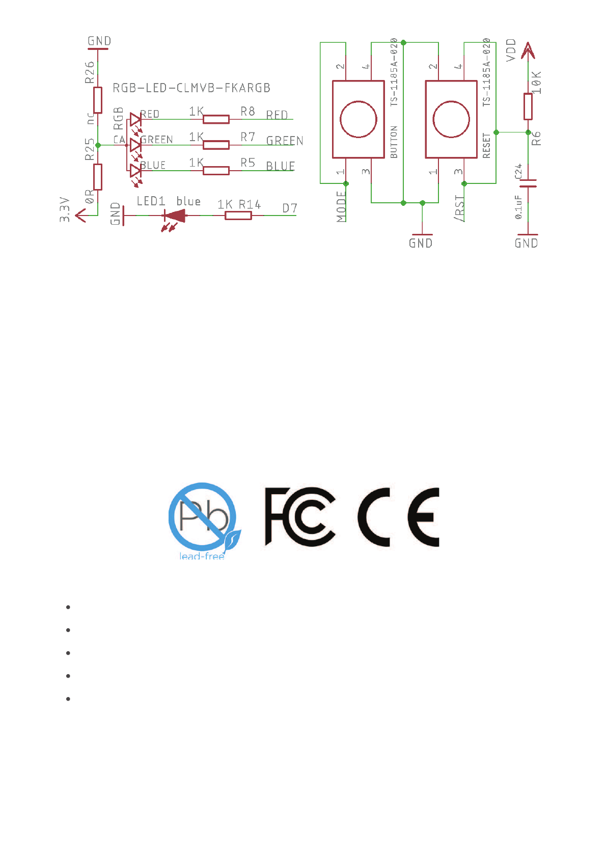
Schematic
Power
2018/11/15 Particle Datasheets | Xenon datasheet
https://docs.particle.io/datasheets/mesh/xenon-datasheet/ 15/22
nRF52840
SPI FLASH
Interfaces
2018/11/15 Particle Datasheets | Xenon datasheet
https://docs.particle.io/datasheets/mesh/xenon-datasheet/ 16/22
Xenons are available from store.particle.io in single quantities.
Model Number: XENN
RoHS
CE
FCC ID: 2AEMI-XENN
IC: 20127-XENN
Ordering information
Qualification and approvals
Product Handling
ESD Precautions
2018/11/15 Particle Datasheets | Xenon datasheet
https://docs.particle.io/datasheets/mesh/xenon-datasheet/ 17/22
The Xenon contains highly sensitive electronic circuitry and is an Electrostatic Sensitive
Device (ESD). Handling Xenon without proper ESD protection may destroy or damage it
permanently. Proper ESD handling and packaging procedures must be applied
throughout the processing, handling and operation of any application that incorporates
Xenon. ESD precautions should be implemented on the application board where the
Xenon is mounted. Failure to observe these precautions can result in severe damage to
the Xenon!
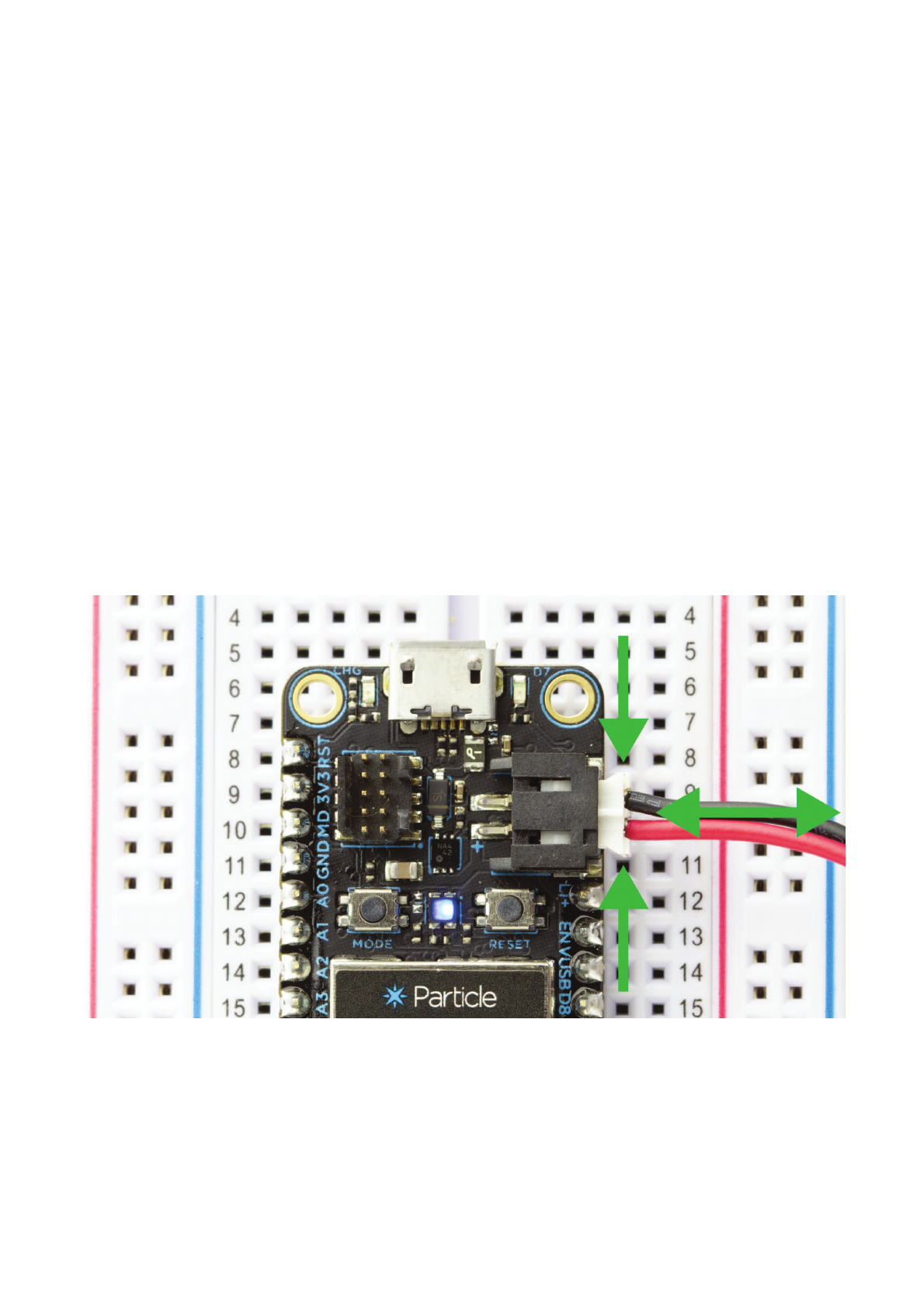
There are four connectors on the Xenon that will get damaged with improper usage. The
JST connector on the circuit board, where you plug in the LiPo battery, is very durable but
the connector on the battery itself is not. When unplugging the battery, take extra
precaution to NOT pull the connector using the wires, but instead hold the plug at its base
to avoid putting stress on the wires. This can be tricky with bare hands - nose pliers are
your friend here.
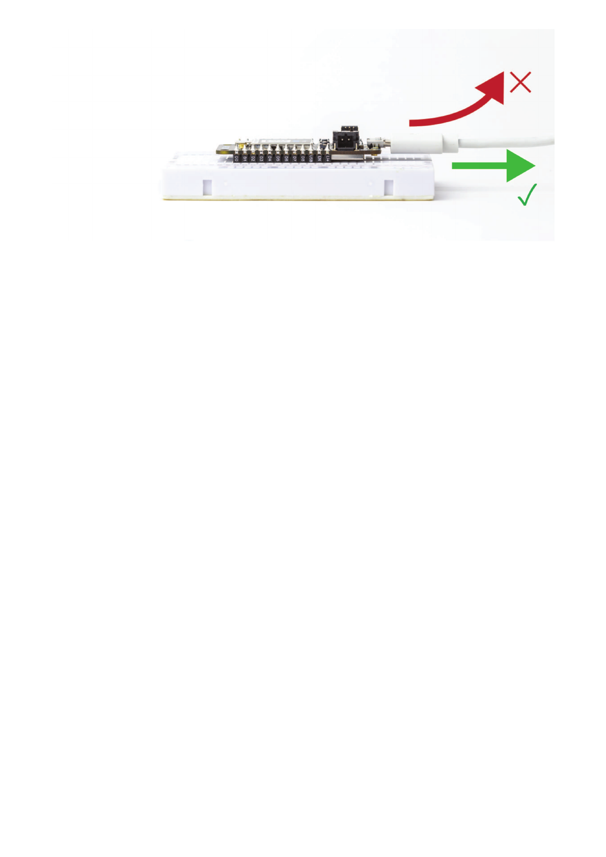
The micro B USB connector on the Xenon is soldered on the PCB with large surface pads
as well as couple of through hole anchor points. Despite this reinforcement, it is very easy
to rip out the connector if too much stress is put on in the vertical direction.
Connectors
2018/11/15 Particle Datasheets | Xenon datasheet
https://docs.particle.io/datasheets/mesh/xenon-datasheet/ 18/22
The u.FL antenna connector is a very fragile piece of hardware ( and is fancy too with all
the gold plating). The connector was not designed to be constantly plugged and
unplugged. Care must be taken not to put stress on it at any time (yes, swinging the
Xenon by the antenna is a very bad idea, this is not your cat). The antenna pin is also the
most static sensitive and you can destroy the radio with improper handling. If you are
feeling adventurous, we highly recommend putting a tiny dab of glue (epoxy, rubber
cement, liquid tape or hot glue) on the connector to securely hold the plug in place.
The 10 pin SWD connector provides an easy in-system debugging access to the device.
The pins on the connector can easily be damaged if the mating connector cable is
inserted improperly. If you are trying to debug the device, you probably are not in a good
mood to begin with. The last thing you want is to render the connector useless. Be nice,
and be gentle on the connector. Good luck with the debugging!
The breadboard provided with the Xenon is specifically designed to require low insertion
force. This makes it easy to plug the Xenon in and out of the breadboard. If you end up
using a different breadboard, remember that it may require more force. In this case,
always remember to pinch-hold your precious Xenon by the sides (along the header pins)
when plugging-unplugging and not by the USB connector (don't be this person).
The Xenon comes preprogrammed with a bootloader and a user application called Tinker.
This application works with an iOS and Android app also named Tinker that allows you to
Breadboarding
Default settings
2018/11/15 Particle Datasheets | Xenon datasheet
https://docs.particle.io/datasheets/mesh/xenon-datasheet/ 19/22
very easily toggle digital pins, take analog and digital readings and drive variable PWM
outputs.
The bootloader allows you to easily update the user application via several different
methods, USB, OTA, Serial Y-Modem, and also internally via the Factory Reset procedure.
All of these methods have multiple tools associated with them as well.
Federal Communication Commission Interference Statement This equipment has been
tested and found to comply with the limits for a Class B digital device, pursuant to Part 15
of the FCC Rules. These limits are designed to provide reasonable protection against
harmful interference in a residential installation. This equipment generates, uses and can
radiate radio frequency energy and, if not installed and used in accordance with the
instructions, may cause harmful interference to radio communications. However, there is
no guarantee that interference will not occur in a particular installation. If this equipment
does cause harmful interference to radio or television reception, which can be determined
by turning the equipment off and on, the user is encouraged to try to correct the
interference by one of the following measures:
Reorient or relocate the receiving antenna.
Increase the separation between the equipment and receiver.
Connect the equipment into an outlet on a circuit different from that to which the
receiver is connected.
Consult the dealer or an experienced radio/TV technician for help.
FCC Caution: Any changes or modifications not expressly approved by the party
responsible for compliance could void the user's authority to operate this equipment. This
device complies with Part 15 of the FCC Rules. Operation is subject to the following two
conditions:
1. This device may not cause harmful interference, and
2. This device must accept any interference received, including interference that may
cause undesired operation.
FCC Radiation Exposure Statement: This equipment complies with FCC radiation
exposure limits set forth for an uncontrolled environment. This transmitter module must
not be co-located or operating in conjunction with any other antenna or transmitter. This
FCC IC CE Warnings and End Product Labeling
Requirements

2018/11/15 Particle Datasheets | Xenon datasheet
https://docs.particle.io/datasheets/mesh/xenon-datasheet/ 20/22
End equipment should be installed and operated with a minimum distance of 20
centimeters between the radiator and your body.
IMPORTANT NOTE: In the event that these conditions can not be met (for example certain
laptop configurations or co-location with another transmitter), then the FCC authorization
is no longer considered valid and the FCC ID can not be used on the final product. In
these circumstances, the OEM integrator will be responsible for re-evaluating the end
product (including the transmitter) and obtaining a separate FCC authorization.
End Product Labeling The final end product must be labeled in a visible area with the
following:
Contains FCC ID: 2AEMI-XENN
Manual Information to the End User The OEM integrator has to be aware not to provide
information to the end user regarding how to install or remove this RF module in the user’s
manual of the end product which integrates this module.
Canada Statement This device complies with Industry Canada’s licence-exempt RSSs.
Operation is subject to the following two conditions:
1. This device may not cause interference; and
2. This device must accept any interference, including interference that may cause
undesired operation of the device.
Le présent appareil est conforme aux CNR d’Industrie Canada applicables aux appareils
radio exempts de licence.
L’exploitation est autorisée aux deux conditions suivantes:
1. l’appareil ne doit pas produire de brouillage;
2. l’utilisateur de l’appareil doit accepter tout brouillage radioélectrique subi, même si le
brouillage est susceptible d’en compromettre le fonctionnement.
Caution Exposure: This device meets the exemption from the routine evaluation limits in
section 2.5 of RSS102 and users can obtain Canadian information on RF exposure and
compliance. Le dispositif répond à l'exemption des limites d'évaluation de routine dans la
section 2.5 de RSS102 et les utilisateurs peuvent obtenir des renseignements canadiens
sur l'exposition aux RF et le respect.
The final end product must be labelled in a visible area with the following: The Industry
Canada certification label of a module shall be clearly visible at all times when installed in
the host device, otherwise the host device must be labelled to display the Industry

2018/11/15 Particle Datasheets | Xenon datasheet
https://docs.particle.io/datasheets/mesh/xenon-datasheet/ 21/22
Canada certification number of the module, preceded by the words “Contains transmitter
module”, or the word “Contains”, or similar wording expressing the same meaning, as
follows:
Contains transmitter module IC: 20127-XENN
This End equipment should be installed and operated with a minimum distance of 20
centimeters between the radiator and your body. Cet équipement devrait être installé et
actionné avec une distance minimum de 20 centimètres entre le radiateur et votre corps.
T
h
e
e
n
d
u
s
e
r
m
a
n
u
a
l
s
h
a
l
l
in
cl
u
d
e
a
l
l
r
e
q
u
ir
e
d
r
e
g
u
l
a
t
o
r
y
in
f
o
r
m
a
t
io
n
/
w
a
r
n
in
g
a
s
s
h
o
w
n
in
The end user manual shall include all required regulatory information/warning as shown in
t
h
is
m
a
n
u
a
l
.
this manual.
Revision Date Author Comments
v001 26 Oct 2018 MB Initial release
Web
https://www.particle.io
Community Forums
https://community.particle.io
Email
https://support.particle.io
Revision history
Known Errata
Contact

2018/11/15 Particle Datasheets | Xenon datasheet
https://docs.particle.io/datasheets/mesh/xenon-datasheet/ 22/22