Partner Tech MD150M Mifare USB Reader User Manual Mifare USB Reader
Partner Tech Corporation Mifare USB Reader Mifare USB Reader
MD 150M Manual English version
Users’ Manual
Product:
Mifare USB Reader
Model:
MD-150M
Federal Communication Commission Interference Statement
This equipment has been tested and found to comply with the limits for a Class
B digital device, pursuant to Part 15 of the FCC Rules. These limits are
designed to provide reasonable protection against harmful interference in a
residential installation. This equipment generates, uses and can radiate radio
frequency energy and, if not installed and used in accordance with the
instructions, may cause harmful interference to radio communications.
However, there is no guarantee that interference will not occur in a particular
installation. If this equipment does cause harmful interference to radio or
television reception, which can be determined by turning the equipment off and
on, the user is encouraged to try to correct the interference by one of the
following measures:
- Reorient or relocate the receiving antenna.
- Increase the separation between the equipment and receiver.
- Connect the equipment into an outlet on a circuit different from that to which
the receiver is connected.
- Consult the dealer or an experienced radio/TV technician for help.
This device complies with Part 15 of the FCC Rules. Operation is subject to the
following two conditions:
(1) This device may not cause harmful interference, and
(2) This device must accept any interference received, including interference
that may cause undesired operation.
INFORMATION TO USER
To assure continued compliance, (example - use only shielded interface
cables when connecting to computer or peripheral devices) any changes
or modifications not expressly approved by the party responsible for
compliance could void the user’s authority to operate this equipment.

MD-150M/MK-1500M User Manual
─ Table of contaens ─
I. MD-150M Specification ----------------------------- 3
II. Communication protocol -------------------------- 5
III. MD-150M command list ------------------------------ 6
IV. MD-150M command description ----------------- 7
NOTE
This document is written by SUNION Electronic Corp. SUNION Electronic Corp.
reserves the right to change devices or specifications detailed herein at any time
without notice. Any third party is forbidden strictly to copy, edit, modify or quote the
contents of this document without written approval from SUNION electronic Corp.
SUNION’s products are not authorized for use as critical components in life support
devices or systems.
Copyright 2003~2007, SUNION Electronic Corporation All right reserved.
- 2 -
MD-150M User Manual
I. MD-150 M Reader Specification
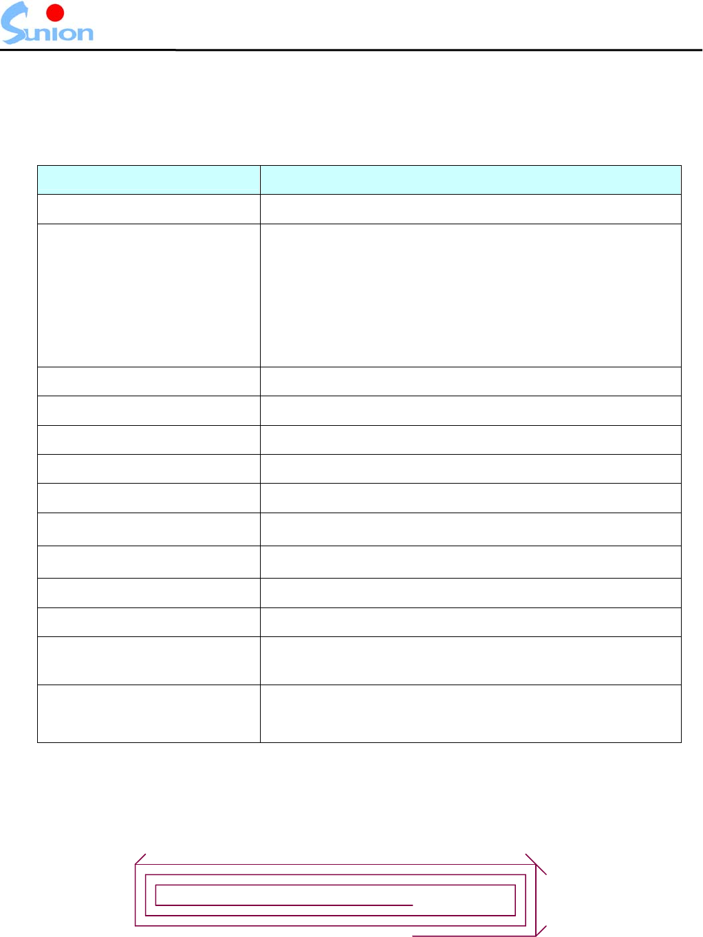
1 .Reader Specification
Part Number MD-150M
RF Transmit Frequency 13.56 MHz
Supported Transponder
Mifare_UltraLight
Mifare_One(S50)
Mifare_One(S70)
Mifare_Pro(X)
Mifare_DESFire
Maximum Reading Range* 25~30 mm
Reading Times 150 ms
Power Supply DC 5V/ 500mA Regulated
Power Consumption 68mA in operation
Communications Parameters 9600 baud, 8 data bits, no parity, 1 start bit, 1 stop bit
Operating Temperature 0°C ~ 55°C
Storage Temperature -25°C ~ 85°C
Storage Humidity 5 ~ 95%RH non-condensing
Communications Interface Mini USB
Dimension (L × W × H) MD-150M (PCBA) : 70mm × 30mm × 6.5mm
Other
1 Status indicators 1 Buzzer
Antenna On board or external (option)
* Reading range may vary in depend on different transponder type.
2 . Antenna Specification
58.81mm
5.26mm
Wire Diameter:0.3mm
Wire-wire distance:0.5mm
- 3 -
MD-150M/MK-1500M User Manual
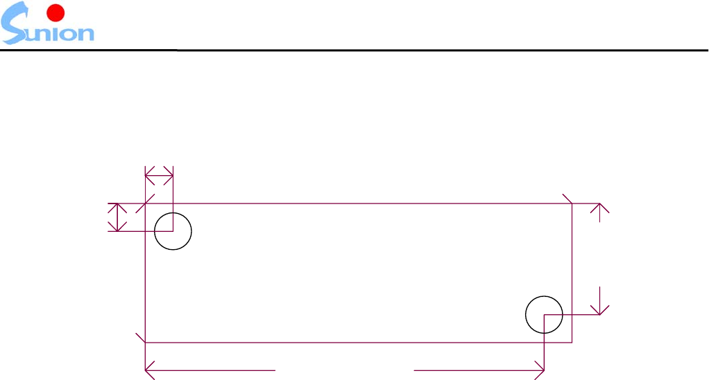
3. Dimension
70mm
0
4.275mm
2.575mm
66.875mm
26.975mm
0
30mm
孔
2mm
孔
2mm
- 4 -
MD-150M/MK-1500M User Manual
II. Communication protocol
This machine passes USB interface and computer end line homework in order to use a
USB connecting wire, USB of the homework is transfered to the driver of Serial Port through
can offer by institute of our company under the environment of Microsoft Windows XP/2000 (#1)
Succeed RS-232 signal USB signal simulation; So user meet device in operating system is it
increase one group communication mound newly to find on the administrator after the last
copies of machine on installation driver (COM PORT) ; Procedure of user can is it communicate
to go on through this communication between mound and copies of machine.
MD-150M are using t he international S tandard UART communication for mat,
and support RS-232 interface with communication parameters set to 9600.N.8.1.
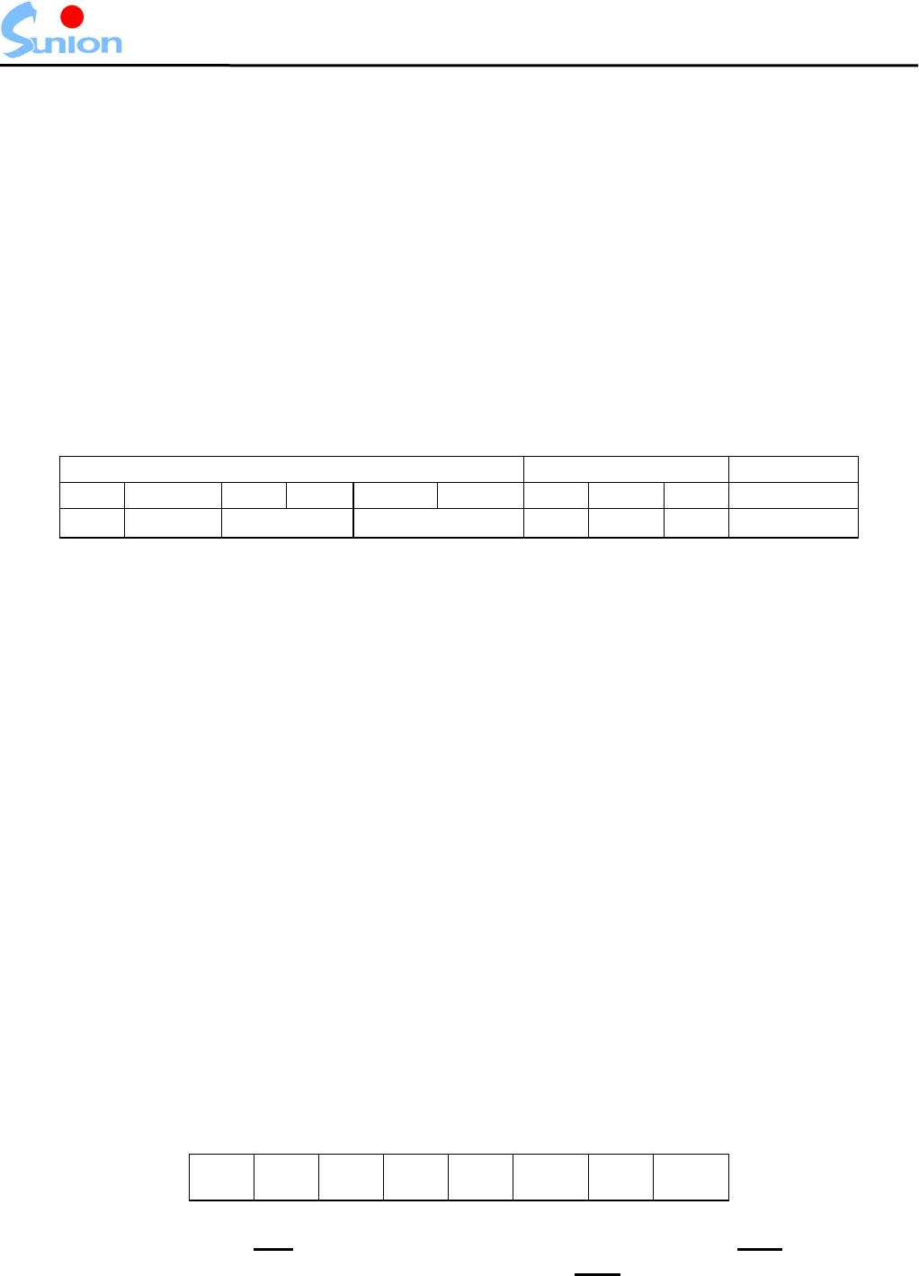
DA TA format are as follows:
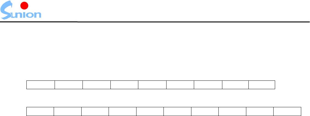
HEADER DATA CHECK
SOH PT ID1 ID2 FC1 FC2 STX DATA ETX BCC
01H Identify Reader ID Function Code 02H Data 03H Checksum
Description:
1. SOH, STX and ET X are all cont ained with one byte and used f or control byte, the
definition is:
SOH=01H, STX=02H, ETX=03H
Note: The “SOH” is the start byte for current command set
The “STX” is the start byte for “Data”
The “ETX” is the end byte for “Data”
You will need these to judge the data length you transmitted or received; the
data length will vary in depend on different command you given
2. PT (Packet T ype) is used to identify w here is the message come s from; “S” means it
comes from PC and “s” means from the reader.
3. ID1, ID2 are the ID codes of reader, the value is always “01”.
4. FC1 and F C2 are function codes, and relat ed to the DA TA, the relative dat a please
refers to the next page.
5. BCC is checksum,from SOH to ETX one byte do “xor”,then do “or” 20H.
Ex. Reader responds:
SOH “S” “01” “A1” STX “010” ETX BCC
BCC = 01H xor 53H xor 30H xor 31H xor 41H xor 31H xor 02H
Xor 30H xor 31H xor 30H xor 03H or 20H =33H
(#1) : Driver please to our company website download, procedure this by Prolific Technology Inc.
Offer.
- 5 -
MD-150M User Manual
III. USB Reader Command list
Function Code Description Page
1 "A0" Switch to Stand-Alone Operation 7
2 "A1" Read card and acquire card ID 8
3 "E1" Acquire model name and firmware version 9
4 "E2" Reset reader 10
5 "K0" Read data in specified page/block 11
6 "K1" Write data into specified page/block 12
7 "K2" Lock specified page/block 13
8 "K3" Set A,B Key value of 32 Sector groups 14
- 6 -
MD-150M/MK-1500M User Manual
IV. USB Reader command description
1. “A0” (Switch to Stand-Alone Operation)
Controller send:
SOH “S” ID1 ID2 “A” “0” STX ETX BCC
USB Reader responds:
SOH “s” ID1 ID2 “A” “0” STX data ETX BCC
Function description:
(1) This function code is able to switch the reader to the “Stand-Alone Operation”.
(2) Data response value is "Y" means successful, "N" means failure, duplicate, or no
data.
Example:
Controller send:
SOH + "S01A0" + STX + ETX + BCC
USB Reader responds:
SOH + "s01A0" + STX + " Y " + ETX + BCC (“Y” means Successful)
- 7 -

MD-150M User Manual
2. “A1” (Read card and acquire card ID)
Controller send:
SOH “S” ID1 ID2 “A” “1” STX ETX BCC
USB Reader responds:
SOH “s” ID1 ID2 “A” “1” STX data ETX BCC
Data description:
(1) The format of “data” will be: Card type (1 byte) + Card ID (16 byte).
(2) Card number is “0” ~ “9” , “A” ~ “F” 。 ex. "00000000003EA88F"。
Function description:
(1) Use this function to acquire card ID number through reader.
(2) The “data” will be “N” if no card presented or failed reading; Such as: STX + “ N ” +
ETX。
Example:
Controller send:
SOH + "S01A1" + STX + ETX + BCC
USB Reader responds:
SOH + "s01A1" + STX + " N " + ETX + BCC (“N” means no card been read or failed
reading)
SOH + "s01A1" + STX + "ME007000000123456" + ETX + BCC
Description:
1. The “data” responded by USB Reader is;
Card type is Multi-Page Typ.
Card ID is "E007000000123456".
- 8 -

MD-150M User Manual
3. “E1” (Acquire model name and firmware version)
Controller send:
SOH “S” ID1 ID2 “E” “1” STX ETX BCC
USB Reader responds:
SOH “s” ID1 ID2 “E” “1” STX date ETX BCC
Data description:
(1) The value of “data” will include current firmware version and model name.
Function description:
(1) Use this function to get model name and firmware version for current reader.
Example:
Controller send:
SOH + "S07E1" + STX + ETX + BCC
USB Reader responds:
SOH + "s07E1" + STX + "V1.01 USB Reader" + ETX + BCC
Description:
1. The current firmware version is: V1.01and the model name is: USB Reader.
2. Sunion reserved the right to update firmware at any time without prior notice.
- 9 -

MD-150M User Manual
4. “E2” ( Reset reader)
Controller send:
SOH “S” ID1 ID2 “E” “2” STX ETX BCC
USB Reader responds:
SOH “s” ID1 ID2 “E” “2” STX data ETX BCC
Function description:
1. Use this function to reset USB Reader.
2. If “data” value responded is “Y” means the set up is successful, “N” means failed,
repeated or no data.
3. CF Card will respond “Y” first then commence reset.
Example:
Controller send:
SOH + "S01E2" + STX + ETX + BCC
USB Reader responds:
SOH + "s01E2" + STX + “Y” + ETX + BCC (“Y” means the set up is successful)
- 10 -
MD-150M User Manual
5. “K0”( Read data in specified page/block)
Controller send:
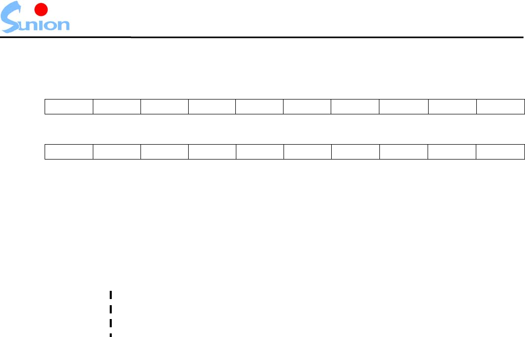
SOH “S” ID1 ID2 “K” “0” STX DATA ETX BCC
USB Reader responds:
SOH “s” ID1 ID2 “K” “0” STX data ETX BCC
Data description:
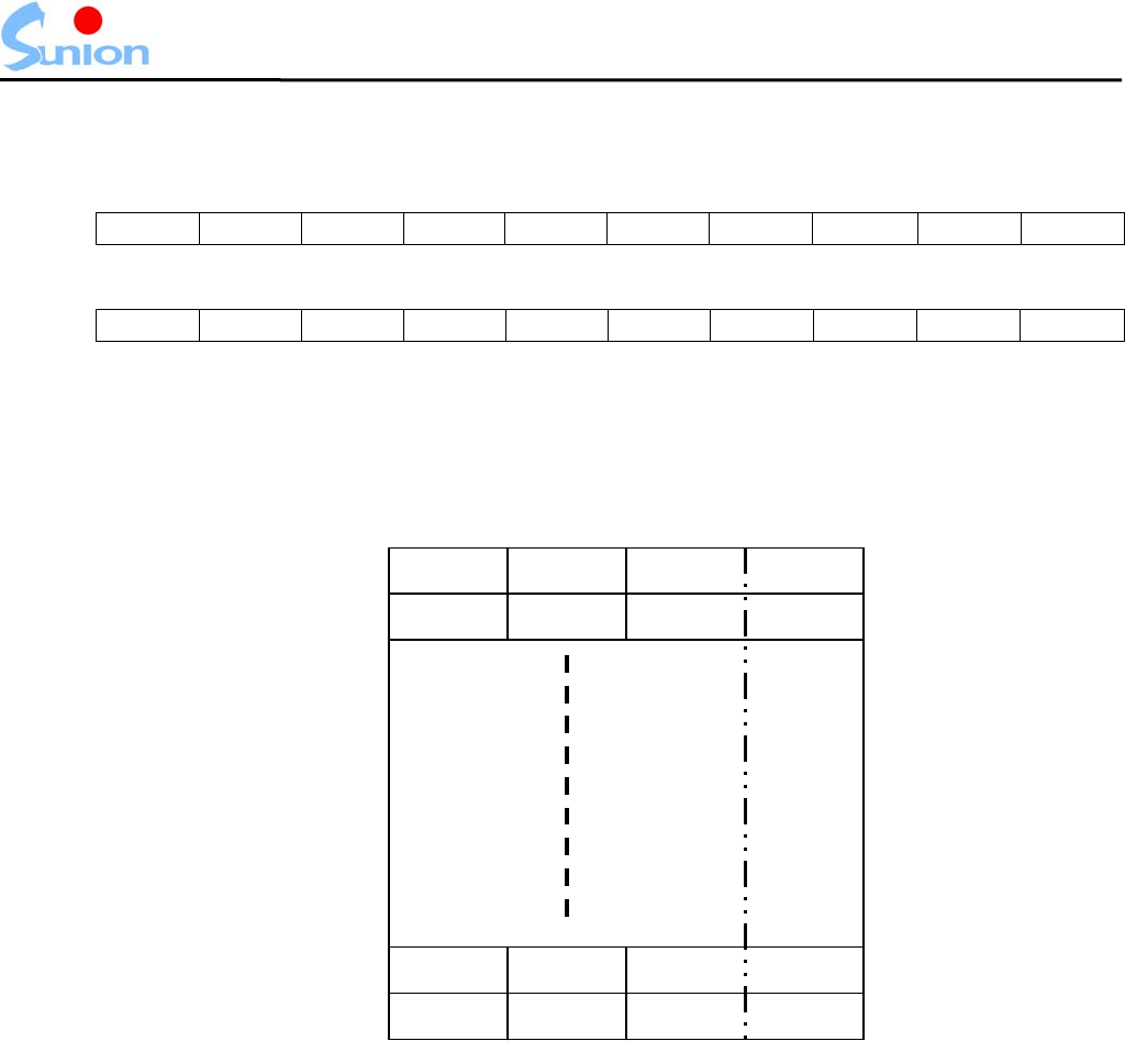
1. “DATA” should be entered as: Card type (1 bytes) + Page/Block number (2 bytes).
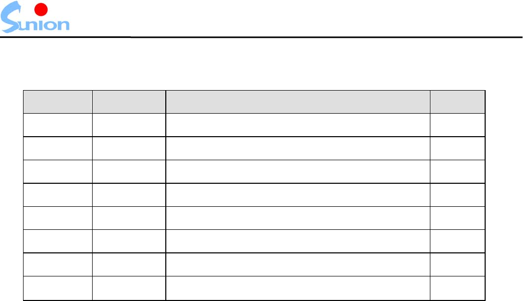
2. When Read Mifare Card, Card type is “M ” + Page/Block number;The page/block
number is fixed to 2 bytes. Number is “00” ~ “3F”(HEX) ,64 Blocks (0 Block is
first)。
Block0 Block1 Block2 Block3
Block4 Block5 Block6 Block7
Block60 Block61 Block62 Block63
Block56 Block57 Block58 Block59
Sector 0
Sector 1
Sector 14
Sector 15
AB
Key
Function description:
1. Use this function to Read Mifare Card Block DATA.
2. Every Sector last Block is A,B Key values.
3. Read Every Sector A Key is always “0”.
Example:
Controller send:
SOH + "S01K0" + STX + "M0E" + ETX + BCC
USB Reader responds:
SOH + "s01K0" + STX + "M00E0000456789ABCDEF1234567898765432" + ETX +
BCC
Description:
1. USB Reader responded:
"0E" ─ The information is from page/block NO.0E.
"0000456789ABCDEF1234567898765432" ─ The dat a ins ide the p age/block
NO.0E.
- 11 -

MD-150M User Manual
6. “K1” (Write data into specified page/block)
Controller send:
SOH “S” ID1 ID2 “K” “1” STX DATA ETX BCC
USB Reader responds:
SOH “s” ID1 ID2 “K” “1” STX data ETX BCC
Data description:
1. DATA should be entered as cars type, page/block number and the information you
want to input, just as follow:
Card type (1 byte) + Page/block number (2 bytes) + Information (16 bytes).
2. When Write Mifare Card, Card type is “M ” + Page/Block number;The page/block
number is “01” ~ “3F”(HEX) ,63 Blocks。
3. Responded “data” value will be as following:
a. If “data” is “Y” means writing is successful.
b. If “data” is “N” means failed or no data.
4. When Write data into specified page/block Sector A,B Key, please attend to
“DATA” value. Because If Responded “data” is “Y” means writing is successful,
Sector A,B Key was written and you can’t read this “DATA” value.
Function description:
1. Use this function to write information into desired block/Page of a card.
2. Use this function to write information into desired A,B Key of a Sector.
Example:
Controller send:
SOH + "S01K1" + STX + "M060000456789ABCDEF1234567898765432" + ETX + BCC
USB Reader responds:
SOH + "s01K1" + STX + "Y" + ETX + BCC
(“Y” means the set up is successful)
USB Reader responds:
SOH + "s01K1" + STX + "N" + ETX + BCC
(“N” means writing is failed or no data)
- 12 -

MD-150M User Manual
7. “K2” (Choose want to use Key)
Controller send:
SOH “S” ID1 ID2 “K” “2” STX DATA ETX BCC
USB Reader responds:
SOH “s” ID1 ID2 “K” “2” STX data ETX BCC
Data description:
1. “DATA” should be compare with A,B Key, sector number you want to lock, just as
follow: Card type (1 byte) + Page/block number (2 bytes)
2. Card type should be entered as: “M” for Multi-Page.
3. The range of page/block number is different in different card type.
4. “K2” function can’t lock a block of EM4135 tag. (Must use “K9”)
5. Responded “data” value will be as following:
If “data” is “Y” means page/block is successfully locked.
If “data” is “N” means failed.
Function description:
1. Use this function to lock the data in specified page/block.
2. Warning! This action is not recoverable, no any unlock maybe perform, use with
extreme care!!!
Example:
Controller send:
SOH + "S01K2" + STX + "M07" + ETX + BCC
USB Reader responds:
SOH + "s01K2" + STX + "Y" + ETX + BCC
(“Y” means page/block is successfully locked)
USB Reader responds:
SOH + "s01K2" + STX + "N" + ETX + BCC
(“N” means failed)
- 13 -
MD-150M User Manual
8. “K3” (Set A,B Key value of 32 Sector groups )
Controller send:
SOH “S” ID1 ID2 “K” “3” STX DATA ETX BCC
USB Reader responds:
SOH “s” ID1 ID2 “K” “3” STX data ETX BCC
Data description:
1. DATA should be entered as cars type, Sector group and the information you want
to input, just as follow:Card type (1 byte) +[Sector group(2 bytes)]+ Information (12
bytes).
2. The range of Sector group of Reader is "01"- "20"(HEX ) 32 groups altogether.
"01": Sector 0
"02": Sector 1
"03": Sector 2
"10": Sector 15
All groups of Sector picture of the Reader to reaching every group Sector of Mifare
card.
3. Responded “data” value will be as following:
If “data” is “Y” means page/block is successfully locked.
If “data” is “N” means failed.
4. The content of the Reader is while wanting to write into Key value of each one
Sector : " 123456789ABC " (12 yards of A , B Key value ).
Function description:
1. Use this function to Set A,B Key value of 32 Sector groups.
2. Can just use K0 to need K2 movements effectively after needing to use this
function.
3. As want to revise within Mifare card , must establish Key of this Sector to the
mould group first , Then choose to want Key of authentication , could read
and write the materials within Mifare card in this way.
Example:
Controller send:
SOH + "S01K3" + STX + " M01123456789ABC " + ETX + BCC
USB Reader responds:
SOH + "s01K3" + STX + "Y" + ETX + BCC
(“Y” means page/block is successfully locked)
Description:
1. USB Reader responded:
"M01" ─ Write into the first group.
"123456789ABC " ─ The first group A,B Key Sector 0.
- 14 -