Pasco Specialty And Mfg Equipopotential Field Mapper Pk 9023 Users Manual 0
2015-02-06
: Pasco-Specialty-And-Mfg Pasco-Specialty-And-Mfg-Equipopotential-And-Field-Mapper-Pk-9023-Users-Manual-516945 pasco-specialty-and-mfg-equipopotential-and-field-mapper-pk-9023-users-manual-516945 pasco-specialty-and-mfg pdf
Open the PDF directly: View PDF ![]() .
.
Page Count: 18
Copyright © October 1990 $5.00
Instruction Manual and
Experiment Guide for
the PASCO scientific
Model PK-9023
012-04346B
05/91
10101 Foothills Blvd. • P. O. Box 619011 • Roseville, CA 95661-9011 USA
Phone (916) 786-3800 • FAX (916) 786-8905 • TWX 910-383-2040
scientific
Instructional Manual and
Experiment Guide for the
PASCO scientific Model
PK-9023
FIELD MAPPER
10101 Foothills Blvd. • P. O. Box 619011 • Roseville, CA 95661-9011 USA
Phone (916) 786-3800 • FAX (916) 786-8905 • TWX 910-383-2040
scientific
Instructional Manual and
Experiment Guide for the
PASCO scientific Model
PK-9023
FIELD MAPPER
EQUIPOTENTIAL AND
FIELD MAPPER

012-04346B
scientific
Section Page
Copyright, Warranty, and Equipment Return................................................... ii
Introduction ...................................................................................................... 1
Equipment......................................................................................................... 1
Equipment Setup............................................................................................... 2
Experiments
Parallel Plate Capacitor ........................................................................ 4
Point Source and Guard Ring ............................................................... 4
Dipoles of Opposite Charge ................................................................. 5
Dipoles of Like Charge......................................................................... 5
Floating Electrode................................................................................. 6
Floating Insulator.................................................................................. 6
Line and Circular Source ...................................................................... 7
Line and "Sharp" Point ......................................................................... 7
Triode.................................................................................................... 8
Fluid Mechanism .................................................................................. 8
Appendix: Silver conductive ink Material Safety Data Sheet .......................... 9
Table of Contents
i

012-04346B
scientific
ii
Copyright Notice
The PASCO scientific Model PK-9023 Equipotential and
Field Mapper manual is copyrighted and all rights reserved.
However, permission is granted to non-profit educational
institutions for reproduction of any part of this manual
providing the reproductions are used only for their laborato-
ries and are not sold for profit. Reproduction under any
other circumstances, without the written consent of PASCO
scientific, is prohibited.
Limited Warranty
PASCO scientific warrants this product to be free from
defects in materials and workmanship for a period of one
year from the date of shipment to the customer. PASCO
will repair or replace, at its option, any part of the product
Please—Feel free to duplicate this manual
subject to the copyright restrictions below.
Copyright and Warranty
Should this product have to be returned to PASCO scientific,
for whatever reason, notify PASCO scientific by letter or
phone BEFORE returning the product. Upon notification,
the return authorization and shipping instructions will be
promptly issued.
NOTE: NO EQUIPMENT WILL BE ACCEPTED
FOR RETURN WITHOUT AN AUTHORIZATION.
When returning equipment for repair, the units must be
packed properly. Carriers will not accept responsibility for
damage caused by improper packing. To be certain the unit
will not be damaged in shipment, observe the following
rules:
1. The carton must be strong enough for the item shipped.
2. Make certain there is at least two inches of packing
material between any point on the apparatus and the
inside walls of the carton.
3. Make certain that the packing material can not shift in
the box, or become compressed, thus letting the
instrument come in contact with the edge of the box.
Equipment Return
which is deemed to be defective in material or workman-
ship. This warranty does not cover damage to the product
caused by abuse or improper use. Determination of whether
a product failure is the result of a manufacturing defect or
improper use by the customer shall be made solely by
PASCO scientific. Responsibility for the return of equip-
ment for warranty repair belongs to the customer. Equip-
ment must be properly packed to prevent damage and
shipped postage or freight prepaid. (Damage caused by
improper packing of the equipment for return shipment will
not be covered by the warranty.) Shipping costs for
returning the equipment, after repair, will be paid by
PASCO scientific.
scientific
1
012-04346B
Introduction
10101 Foothills Blvd. • P. O. Box 619011 • Roseville, CA 95661-9011 USA
Phone (916) 786-3800 • FAX (916) 786-8905 • TWX 910-383-2040
scientific
Instructional Manual and
Experiment Guide for the
PASCO scientific Model
PK-9023
FIELD MAPPER
10101 Foothills Blvd. • P. O. Box 619011 • Roseville, CA 95661-9011 USA
Phone (916) 786-3800 • FAX (916) 786-8905 • TWX 910-383-2040
scientific
Instructional Manual and
Experiment Guide for the
PASCO scientific Model
PK-9023
FIELD MAPPER
-+
The PASCO scientific MODEL PK-9023 Field Mapper
consists of two basic elements. The first is a carbon impreg-
nated paper in the resistance range of 5 KΩ to 20 KΩ per
square. This paper forms the conducting medium or space
between the electrodes. The second element is a conductive
ink dispensed from a pen. The ink is produced from silver
particles in a suspension liquid. As the ink dries, the silver
flakes settle on top of each other forming a conductive path,
(or conductive ink electrodes). The resistance of the ink is
between .03 and .05 Ω/cm for a 1 mm wide line.
Because the paper has a finite resistance, a current must flow
through it to produce a potential difference. This current is
supplied by the conductive ink electrodes which causes a
potential drop to occur across the paths. Because of the
large difference between the ink’s resistance and the
resistance of the paper, this potential drop is less than 1% of
that produced across the paper. Therefore, for all practical
purposes the potential drop across the electrodes may be
considered negligible.
Equipment
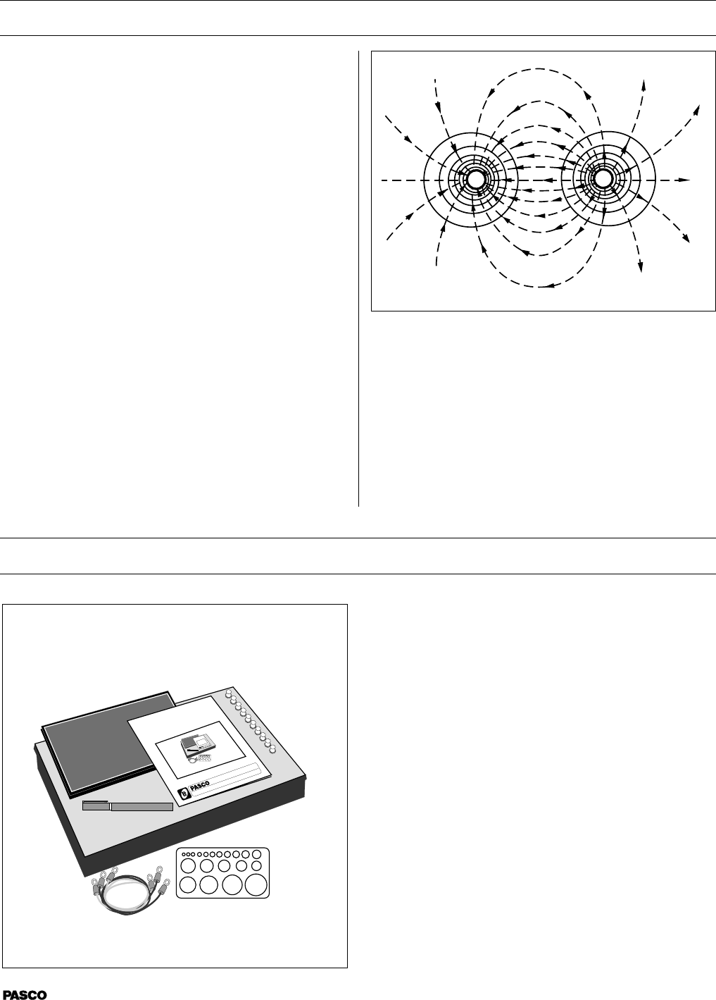
Equipotential and Field Lines
It would be desirable that the potential measuring instrument
have an infinite impedance. An electrometer such as the
PASCO Model ES-9054B would be optimal, however, a
standard electronic voltmeter such as PASCO's SE-9589
Handheld Digital Multimeter with a 10 MΩ (or higher) input
impedance is sufficient. Since this impedance is at least 100
times greater than that of the paper, the greatest distortion of
the field which can be produced by the voltmeter is approxi-
mately 1%.
The PK-9023 Field Mapper includes:
• 100 sheets of conductive paper with 23 x 30 cm grid
• a silver conductive ink pen for approximately 200 ft of
continuous line
• a corkboard working surface
• 10 push pins for attaching the paper to the board
• 3 wires for connecting the conductive paths
• a circle template for drawing the conductive paths.
• a large plastic tray for storing the paper and other
supplies
• Instruction manual and experiment guide.
The following supplies can be ordered separately
from PASCO scientific
Conductive ink pen Model No. PK-9031B
100 sheets of 23 x 30 cm conductive paper with cm grid
Model No. PK-9025A
100 sheets of 30 x 46 cm conductive paper (without grid)
Model No. PK-9026A
scientific
2
012-04346B
Equipment Setup
Figure 1
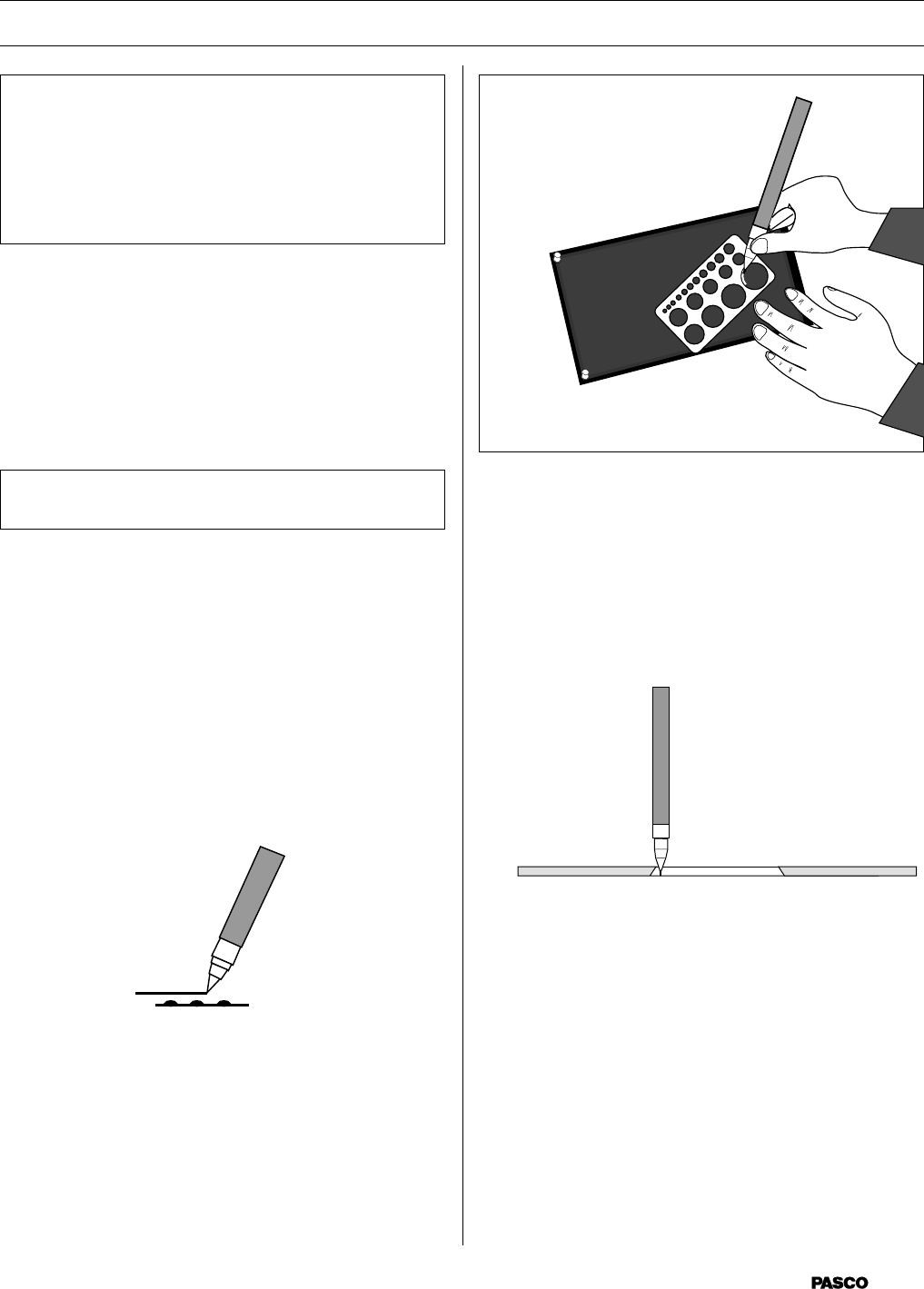
e. A plastic template is included with the PASCO
scientific Field Mapper, for drawing circles. (see
Figure 3) Place the template on the conductive
paper and draw the circles with the conductive ink
pen. (If desired, you may first draw the circle
template with a soft lead pencil and trace over the
pencil line with the ink.)
Figure 3
3. Mount the conductive paper on the corkboard using one
of the metal push pins in each corner.
IMPORTANT:
The silver conductive ink reaches its maximum
conductivity after 20 minutes drying time. For
optimal results plan the timetable for conducting the
experiments and correlate drawing the conductive
ink paths accordingly.
1. Plan and sketch the layout (size, shape and relative
spacing) of the charged paths to be studied on a piece of
scratch paper. These paths can be any two dimensional
shape, such as straight or curved lines, circles, dots,
squares, etc. Since the charged paths will actually be
conductive ink electrodes, they will be referred to as
electrodes.
2. Draw the electrodes on the black paper (see Figure 1).
NOTE: This is the most difficult and crucial part
of the experiment. Follow these steps carefully.
a. Place the conductive paper, printed side up, on a
smooth hard surface. DO NOT attempt to draw the
electrodes while the paper is on the corkboard.
b. Shake the conductive ink pen (with the cap on)
vigorously for 10-20 seconds to disperse any
particle matter suspended in the ink.
c. Remove the cap. Pressing the spring loaded tip
lightly down on a piece of scrap paper while
squeezing the pen barrel firmly starts the ink
flowing. Drawing the pen slowly across the paper
produces a solid line. Drawing speed and exerted
pressure determines the path width. (see Figure 2)
Figure 2
d. Once a satisfactory line is produced on the scrap
paper, draw the electrodes on the black conductive
paper. If the line becomes thin or spotty, draw
over it again. A solid line is essential for good
measurements.
The line will be air dry in 3-5 minutes at room
temperature. However, the medium won’t reach
maximum conductivity until after 20 minutes
drying time.
scientific
3
012-04346B
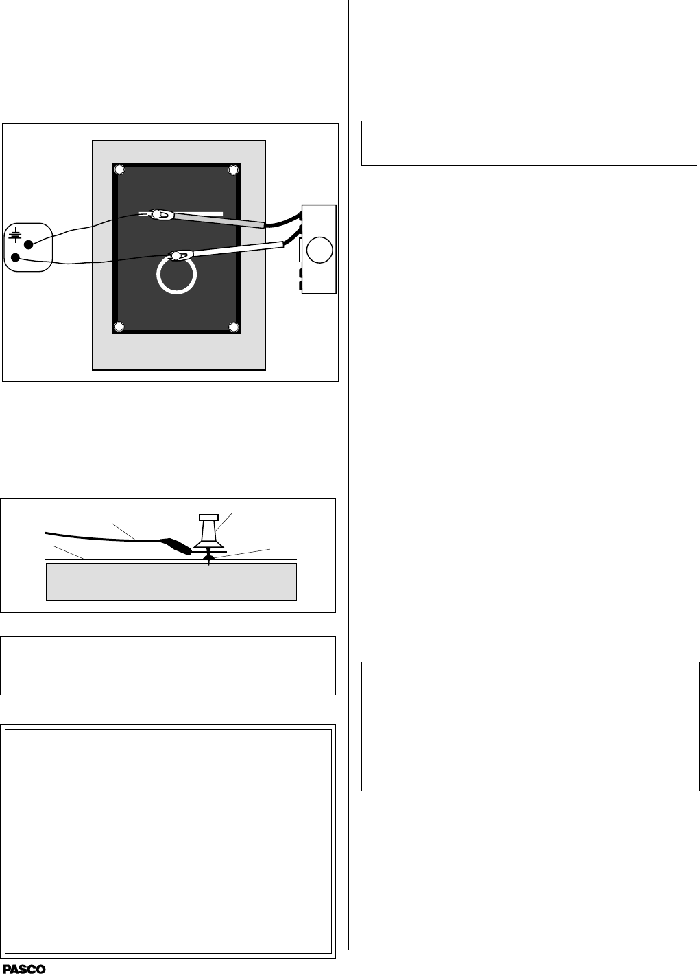
4. Connect the electrodes to a battery, DC power supply,
or any other potential source in the 5 to 20 VDC range
using the supplied connecting wires. (see Figure 4) The
potential source should be capable of supplying 25 mA.
(If possible, the potential should be equal to the full
scale reading of the electronic voltmeter used in the
experiment.)
5. To check the electrodes for proper conductivity connect
one voltmeter lead near the push pin on an electrode.
Touch the voltmeter’s second lead to other points on the
same electrode. If the electrode has been properly
drawn, the maximum potential between any two points
on the same electrode will not exceed 1% of the
potential applied between the two electrodes.
NOTE: This test can only be made if the potential
source is connected across the two electrodes.
If the voltage across the same electrode is greater than
1% of the voltage applied between the two electrodes,
then remove the paper from the corkboard and draw
over the electrodes a second time with the conductive
ink.
6. Equipotentials are plotted by connecting one lead of the
voltmeter (the ground) to one of the electrode push pins.
This electrode now becomes the reference. The other
voltmeter lead (the probe) is used to measure the
potential at any point on the paper simply by touching
the probe to the paper at that point.
To map an equipotential, move the probe until the
desired potential is indicated on the voltmeter. Mark the
paper at this point with a soft lead or light-colored lead
pencil. Continue to move the probe, but only in a
direction which maintains the voltmeter at the same
reading. Continue to mark these points. Connecting the
points produces an equipotential line.
7. To plot field gradients (field lines), neither lead of the
voltmeter is connected to an electrode. Instead, the two
leads of the voltmeter will be placed on the conductive
paper side-by-side at a set distance of separation (one
centimeter is a useful separation to use). It is best to tape
the two leads of the voltmeter together for this proce-
dure (see Figure 7). The technique is to use the voltme-
ter leads to find the direction from an electrode that
follows the path of greatest potential difference from
point-to-point.
NOTE: Do Not attempt to make measurements by
placing the leads on the grid marks on the conduc-
tive paper. Touch the voltmeter leads only on the
solid black areas of the paper. It may be necessary
to use a higher voltmeter sensitivity for this
measurement than was used in measuring
equipotentials.
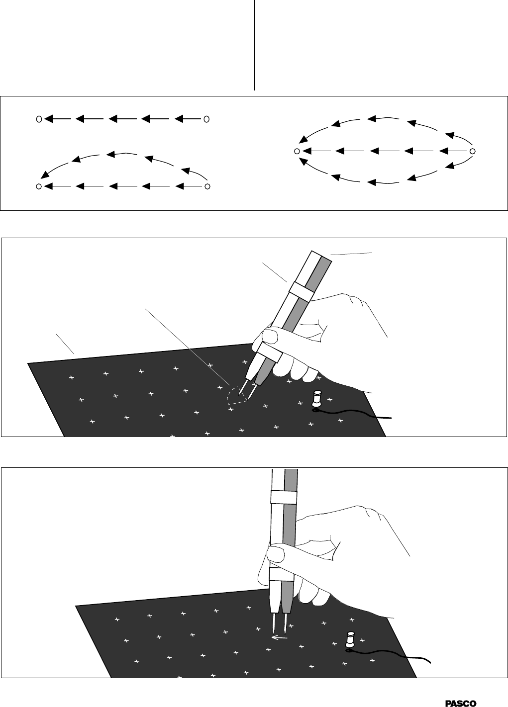
To plot the field lines on the conductive paper, place the
voltmeter lead connected to ground near one of the
dipoles. Place the other voltmeter lead on the paper and
note the voltmeter reading. Now pivot the lead to
several new positions while keeping the ground lead
stationary (see Figure 7). Note the voltmeter readings as
you touch the lead at each new spot on the paper. When
the potential is the highest, draw an arrow on the paper
from the ground lead to the other lead (see Figure 8).
Then move the ground lead to the tip (head) of the
M
Figure 4
Meter
DC Power
supply
a. Place the terminal of a connecting wire over the
electrode, then stick a metal push pin through its
terminal and the electrode into the corkboard.
Make certain that the pin holds the terminal firmly
to the electrode. (see Figure 5).
Push pin
Connecting
wire
Paper Electrode
Figure 5
NOTE: Check that the surface of the terminal
which touches the electrode is clean. A dirty path
may result in a bad contact.
Connect the other end of the wire to the battery.
THE ELECTRONIC VOLTMETER
Two specifications which a voltmeter must meet in
order to be used with the PASCO scientific Field
Mapper are
• first, an input impedance of 10 MΩ or higher
• second, a full scale range which is equal to or higher
than the potential used across the electrodes.
Any commercial electronic voltmeter, either digital
or analog, that meets these specifications is ad-
equate. The PASCO ES-9054B Electrometer or the
SE-9589 Handheld Digital Multimeter are recom-
mended.
scientific
4
012-04346B
arrow. Repeat the action of pivoting and touching with
the front lead until the potential reading in a given
direction is highest. Draw a new arrow. Repeat the
action of putting the ground lead at the tip (head) of
each new arrow and finding the direction in which the
potential difference is highest. Eventually , the arrows
drawn in this manner will form a field line. Return to the
dipole and select a new point at which to place the
voltmeter's ground lead. Again probe with the other lead
until the direction of highest potential difference is
found. Draw an arrow from the ground lead to the other
lead, and repeat the process until a new field line is
drawn. Continue selecting new points and drawing field
lines around the original dipole (see Figure 6).
Figure 8
Figure 6 (Example of 3 field lines between unlike dipoles)
Figure 7
Area to probe in order to
find highest potential
difference
Ground lead for
voltmeter
Tape
Pushpin Electrode to voltage
source (battery or
power supply)
Conductive
paper
Dipole Dipole
1st line
2nd line
3rd line
scientific
5
012-04346B
Experiments
The following are only some suggested experiments in
mapping equipotentials and field gradients using the PASCO
Field Mapper. The true value of the equipment, lies in its
complete flexibility permitting the user to design any system
of charged bodies and then to map the equipotentials and
field gradients.
NOTE: Only power supply connections are shown
in the following schematics. Voltmeter connections
are not shown because they vary depending on
whether equipotentials or field gradients are being
mapped.
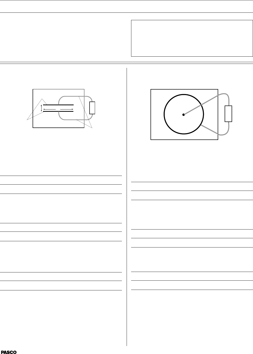
Parallel Plate Capacitor
l
d
Electrodes
DC
Source
Connecting
wires
+
Questions
What is the field outside the capacitor plates?
How does the ratio of the plate length (l) versus separation
(d) affect the fringing effect at the edges of the plates?
What redesign of the plates, or perhaps extra electrodes,
could help eliminate the fringing effect?
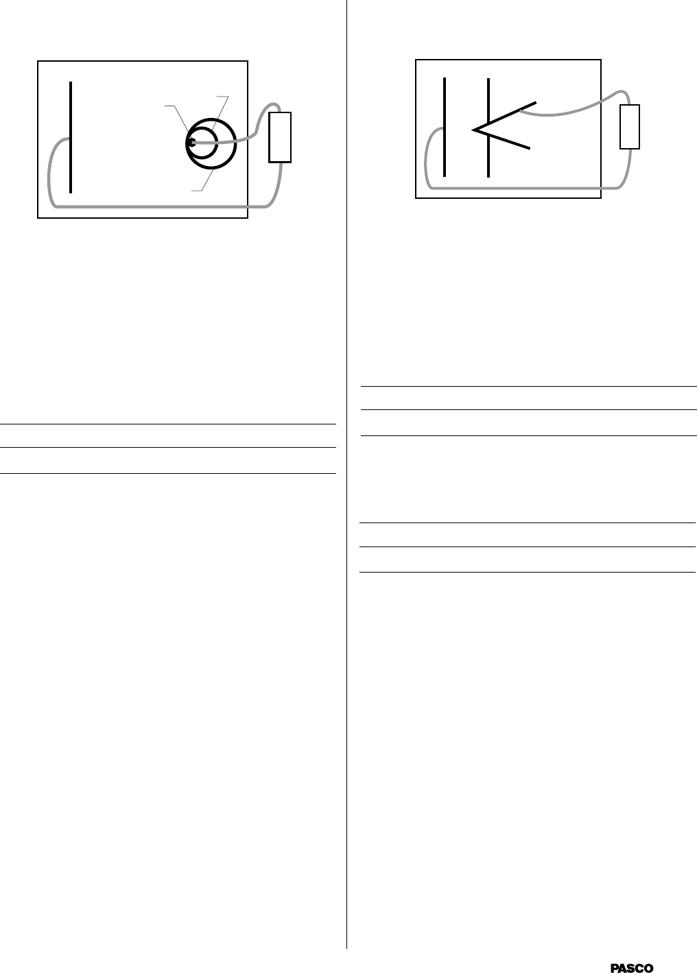
Point Source and Guard Ring
+
Questions
What relation can be derived between the distance from the
center of the point source and the equipotential value?
Would this same relation hold if the system were three
dimensional?
What purpose does the large outer ring serve in this experi-
ment?
scientific
6
012-04346B
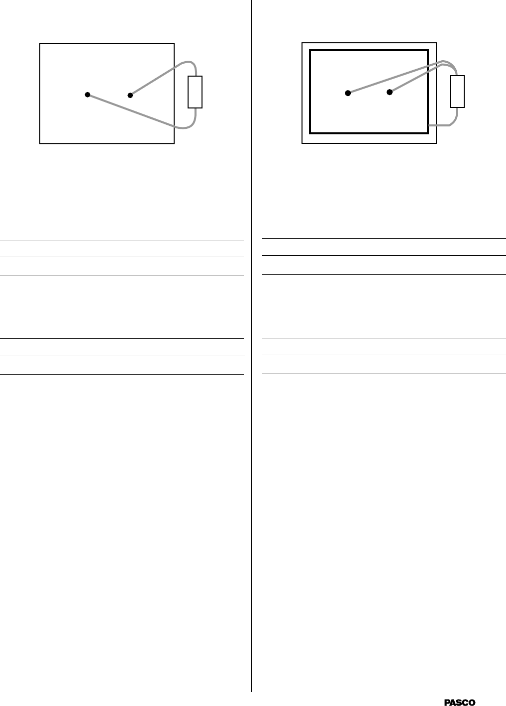
Dipoles of Like Charge
+
Questions
How does the field of this configuration compare with
dipoles of opposite charge? (See experiment “Dipoles of
Opposite Charge”.)
What distortion of the field is produced by the large elec-
trode around the perimeter of the paper?
Dipoles of Opposite Charge
+
Questions
What is the relation between the direction of a maximum
value field gradient and equipotential line at the same point?
(A geometrical relation is desired.)
What effect does the finite size of the black paper have on
the field?
scientific
7
012-04346B
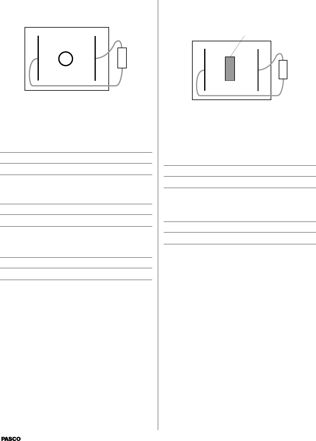
Floating Electrode
+
Before drawing the circular electrode, map the equipotentials
of the two straight electrodes. Draw the circular electrode
and again map the equipotentials.
Questions
How does the circular electrode distort the field?
What is the potential of the circular electrode? Of the area
inside the electrode?
What effect would moving the circular electrode have?
Floating Insulator
Rectangular cut-out
+
Before cutting the rectangular insulator, map the
equipotentials of the two straight electrodes. Cut out a
rectangular section of the paper and again map the
equipotentials.
Questions
How does the rectangular insulator distort the field?
What effect would moving the rectangular insulator have?
scientific
8
012-04346B
Line and Circular Source
ab
c
+
Draw only the line and point source “a.” Map the
equipotentials. Add circular electrode “b” and again map the
equipotentials. Add circular electrode “c” and again map the
equipotentials.
Questions
How is the spacing of equipotentials affected by the increas-
ing diameter of the circular electrode?
Line and “Sharp” Point
a
a
+
At first, do not draw the two electrodes marked “a.” Map
the equipotentials. Add the electrodes “a” and again map the
equipotentials.
Questions
What effect did adding the extra electrodes have on the
spacing of the equipotentials (field strength) around the
point?
Why did the field strength change even though the radius of
the point did not change?
scientific
9
012-04346B
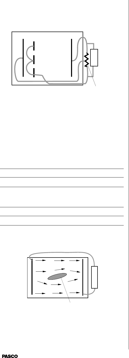
Triode
Equipment needed but not supplied: 5K Potentiometer
a
a
5K
Potentiometer
+
Use a 5 K potentiometer to provide three potentials. Con-
nect the three short electrodes with wires “a.” Do not let
these wires touch the black paper except at the conductive
ink electrodes.
Questions
How is the field in the area between the short electrodes
affected by the potential between the short electrodes and the
closer, long electrode?
Could this paper model of a triode act as an amplifying
device? If not, why not?
Fluid Mechanics Experiments
Cut-out shape
+
-
The PASCO Field Mapper can also be used to examine fluid
flow. In many fluid systems the velocity potential satisfies
the Laplace equations (so does the electromagnetic poten-
tial). Consequently, there is a direct analogy between fluid
flow and electric fields. In particular, the velocity potential
of an incompressible fluid where the flow is both steady and
not rotational satisfies the Laplace equation. A steady flow
of water is a good approximately of this type of flow. Now
the flow is generated by “sources” which supply fluid and
“sinks” which absorb fluid. We are interested in the
“streamlines” which can be thought of as lines traced out by
a particular particle in the fluid. The streamlines begin at the
sources and end at the sinks.
Turning to the Field Mapper, we need to draw electrodes in
the shape of the sources and sinks in the fluid flow to be
examined. Then the electric field lines which we plot
coincide with the streamlines in the fluid flow. (Remember
that the electric field lines are perpendicular to the equipo-
tential lines.) If there is some fixed obstruction in the fluid
glow, we can represent it by cutting the same shape from the
conductive paper. The schematic drawing shows a fluid
flow which is analogous to the flow in a section of pipe
(with frictionless walls). This source is a straight line at the
left, the sink is a straight line at the right. The tear-drop
shaped section cut out of the middle is some obstruction.
The field lines are the corresponding streamlines.
To use the Field Mapper to examine fluid flows, follow these
steps.
1. Make sure that the fluid is incompressible and the flow
is not rotational and steady.
2. Draw electrodes on the conductive paper in the same
shape and position as the sources and sinks in the flow.
3. Cut out sections of the conductive paper in the same
shape and position as the obstructions in the fluid.
4. Connect a battery between the sources and sinks. All
sources should be connected to the same side of the
battery. All sinks should be connected to the opposite
side.
5. Plot the equipotentials and draw lines perpendicular to
these. You can also pick any point and determine the
direction of the maximum field gradient. This is the
direction of the streamlines at that point.

scientific
10
012-04346B
Notes
scientific
11
012-04346B
Appendix
scientific
12
012-04346B

Technical Support
Feedback
If you have any comments about the product or
manual, please let us know. If you have any sugges-
tions on alternate experiments or find a problem in the
manual, please tell us. PASCO appreciates any
customer feedback. Your input helps us evaluate and
improve our product.
To Reach PASCO
For technical support, call us at 1-800-772-8700
(toll-free within the U.S.) or (916) 786-3800.
fax: (916) 786-3292
e-mail: techsupp@PASCO.com
web: www.pasco.com
Contacting Technical Support
Before you call the PASCO Technical Support staff,
it would be helpful to prepare the following infor-
mation:
➤ If your problem is with the PASCO apparatus,
note:
-Title and model number (usually listed on the
label);
-Approximate age of apparatus;
-A detailed description of the problem/sequence
of events. (In case you can’t call PASCO right
away, you won’t lose valuable data.);
-If possible, have the apparatus within reach
when calling to facilitate description of indi-
vidual parts.
➤ If your problem relates to the instruction manual,
note:
- Part number and revision (listed by month and
year on the front cover);
- Have the manual at hand to discuss your ques-
tions.
