Pass and Seymour d b a Legrand DA1104 802.11ac Dual Band In Ceiling WAP User Manual
Pass & Seymour, Inc. d/b/a Legrand 802.11ac Dual Band In Ceiling WAP
UserManual.wiki
>
Pass and Seymour d b a Legrand
>
DA1104 User Manual
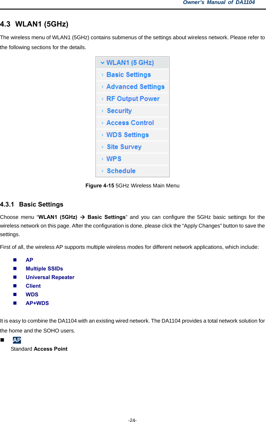
User Manual
Navigation menu
Upload a User Manual
Namespaces
Wiki Guide
HTML
PDF
Info
Views
User Manual
Discussion / Help
Navigation

![II cables and equipment other than manufacturer specified. It is the responsibility of the user to correct any interference caused by such unauthorized modification, substitution or attachment. Manufacturer and its authorized resellers or distributors will assume no liability for any damage or violation of government regulations arising from failing to comply with these guidelines. This device and its antenna(s) must not be co-located or operating in conjunction with any other antenna or transmitter. Declaration of Conformity (R&TTE directive 1999/5/EC) The following items were completed and are considered relevant and sufficient: Essential requirements as in [Article 3] Protection requirements for health and safety as in [Article 3.1a] Testing for electric safety according to [EN 60950] Protection requirements for electromagnetic compatibility in [Article 3.1b] Testing for electromagnetic compatibility in [EN 301 489-1] & [EN 301] Testing according to [489-17] Effective use of the radio spectrum as in [Article 3.2] Testing for radio test suites according to [EN 300 328-2] WARNING: TO PREVENT FIRE OR SHOCK HAZARD, DO NOT EXPOSE THIS PRODUCT TO RAIN OR MOISTURE. THE UNIT MUST NOT BE EXPOSED TO DRIPPING OR SPLASHING WATER. CAUTION: DO NOT OPEN THE UNIT. DO NOT PERFORM ANY SERVICING OTHER THAN THAT CONTAINED IN THE INSTALLATION AND TROUBLESHOOTING INSTRUCTIONS. REFER ALL SERVICING TO QUALIFIED SERVICE PERSONNEL. CAUTION: THIS DEVICE MUST BE INSTALLED AND USED IN STRICT ACCORDANCE WITH THE MANUFACTURER’S INSTRUCTIONS AS DESCRIBED IN THE USER DOCUMENTATION THAT COMES WITH THE PRODUCT. WARNING: POSTPONE INSTALLATION UNTIL THERE IS NO RISK OF THUNDERSTORM OR LIGHTNING ACTIVITY IN THE AREA. When using this device, basic safety precautions should always be followed to reduce the risk of fire, electric shock and injury to persons, including the following: Read all of the instructions {listed here and/or in the user manual} before you operate this equipment. Give particular attention to all safety precautions. Retain the instructions for future reference. Comply with all warning and caution statements in the instructions. Observe all warning and caution symbols that are affixed to this equipment. Comply with all instructions that accompany this equipment. Avoid using this product during an electrical storm. There may be a risk of electric shock from lightning. For added protection for this product during a lightning storm, or when it is left unattended and unused for long periods of time, unplug the power supply, and disconnect the Cat 5e to the DA1104 at the POE Inserter. This will prevent damage to the product due to lightning and power surges. It is recommended that the customer install an AC surge protector in the AC outlet to which this device is connected. This is to avoid damaging the equipment by local lightning strikes and other electrical surges. Operate this product only from the type of power source indicated on the product’s marking label.](https://usermanual.wiki/Pass-and-Seymour-d-b-a-Legrand/DA1104/User-Guide-2540229-Page-3.png)
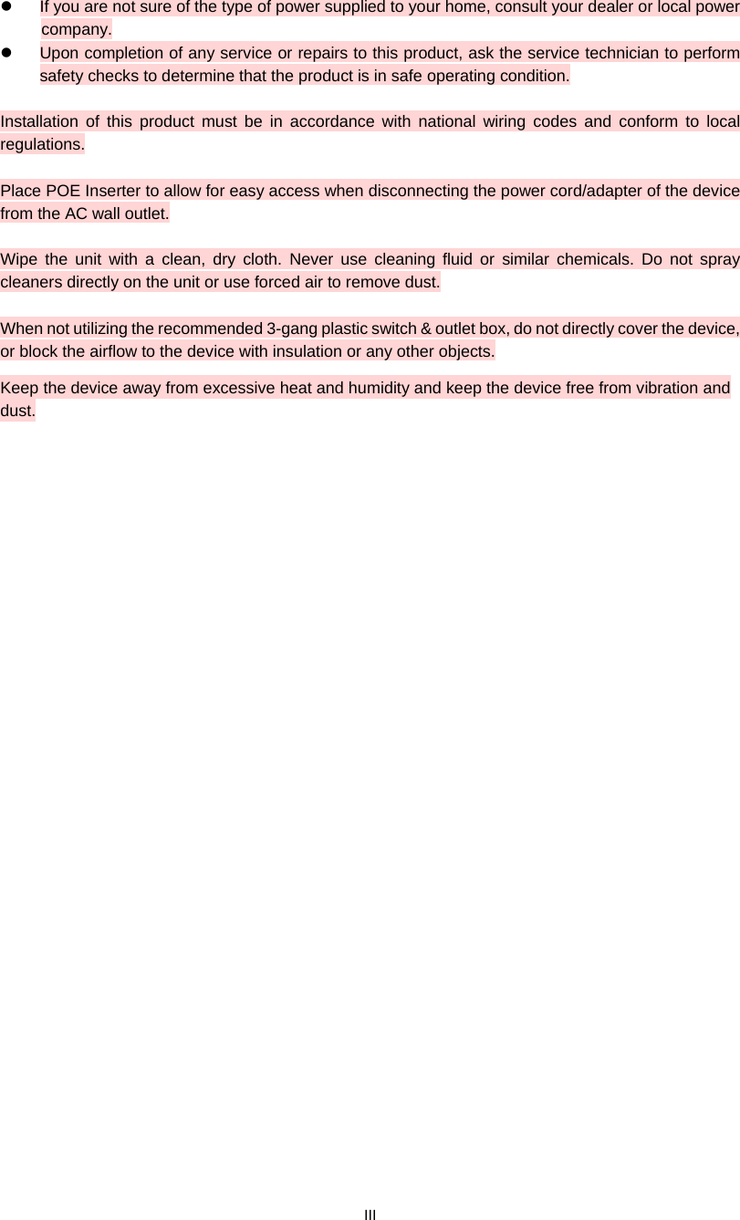


![Owner’s Manual of DA1104 -7- Chapter 2. Hardware Installation Please follow the instructions below to connect DA1104 to the existing network devices and your computers. 2.1 Product Installation Overview Installation Drawing : Figure 2-1 DA1104 Product Installation Drawing Reset Button Dual Band WAP LEDs From Internet AC Adapter PoE Injector Cat 5 cable [MR1]: Drawing labels need to be cleaned up](https://usermanual.wiki/Pass-and-Seymour-d-b-a-Legrand/DA1104/User-Guide-2540229-Page-16.png)


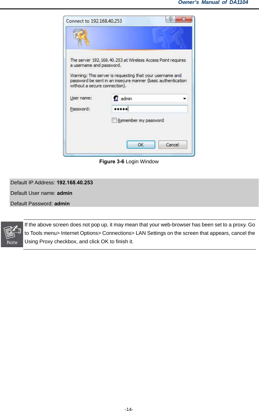


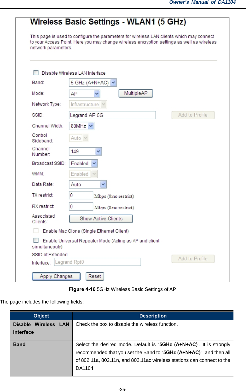
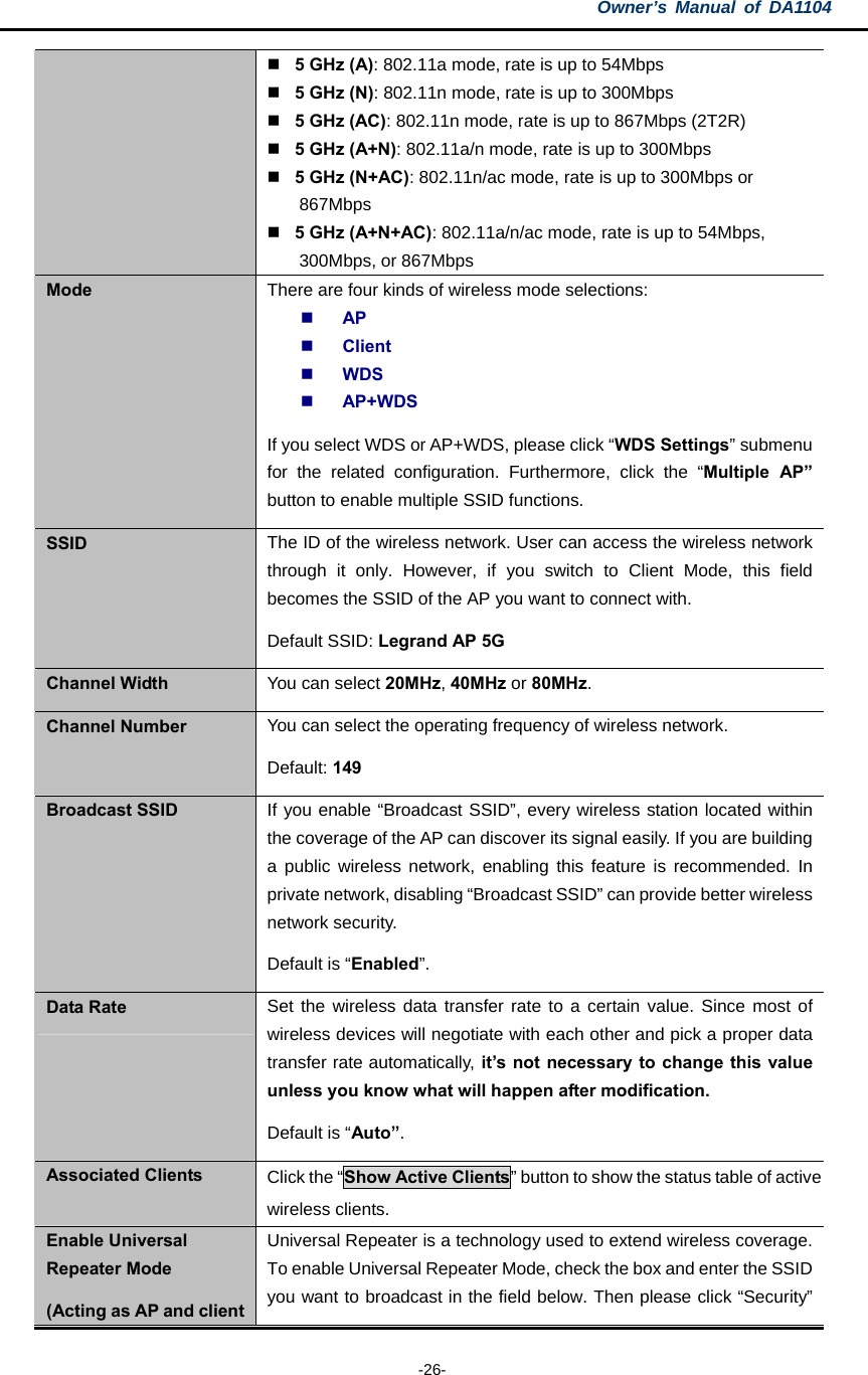
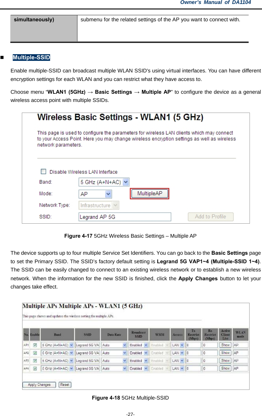
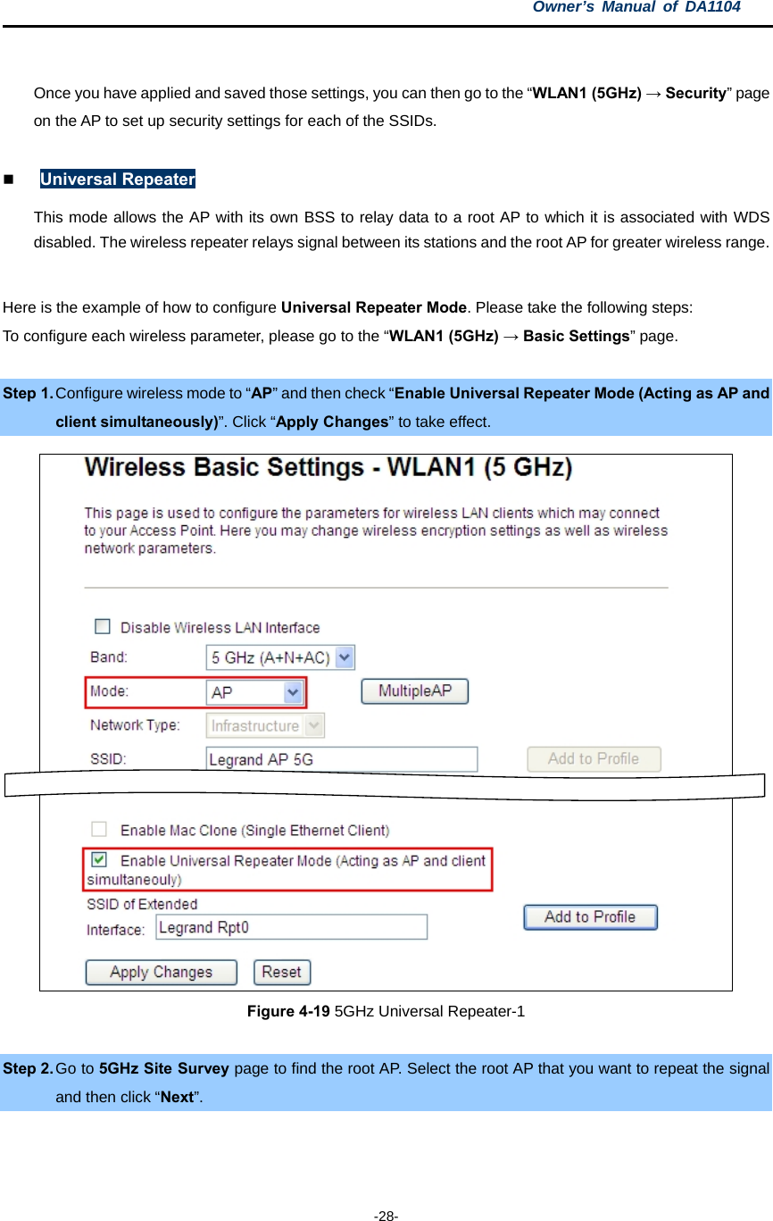

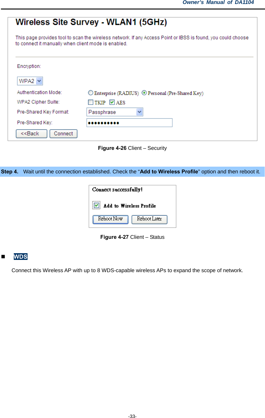
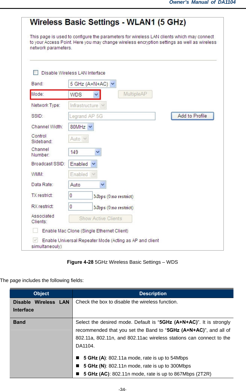
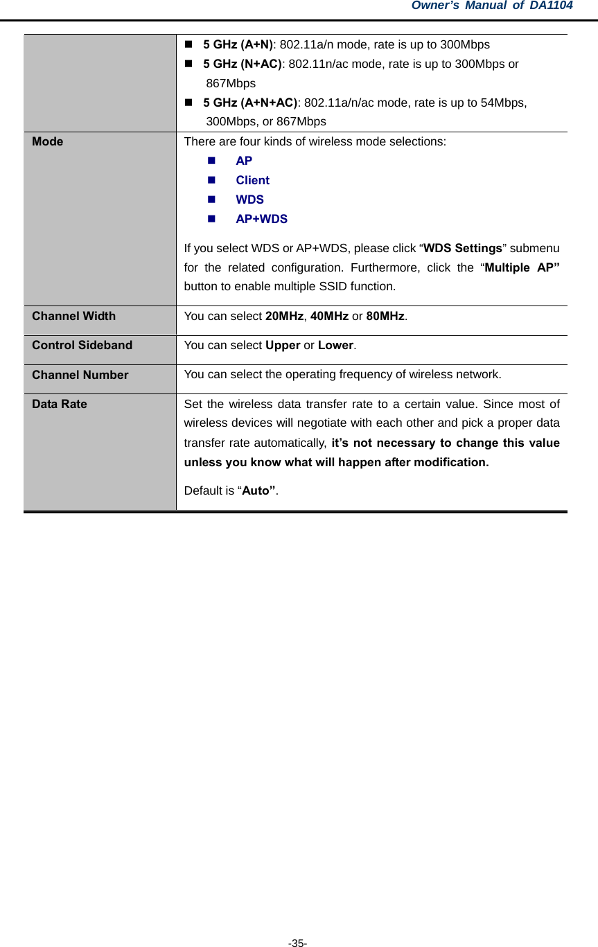
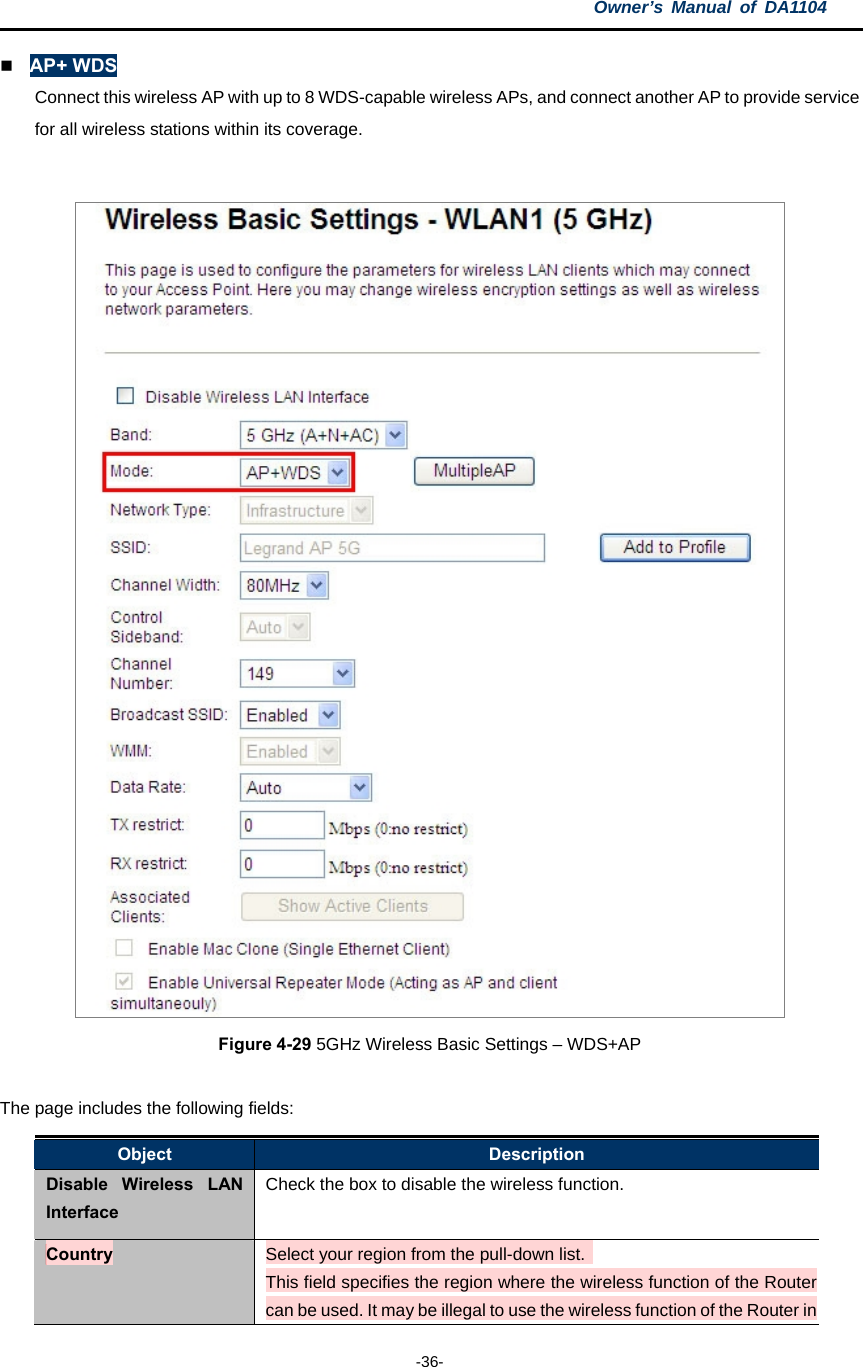
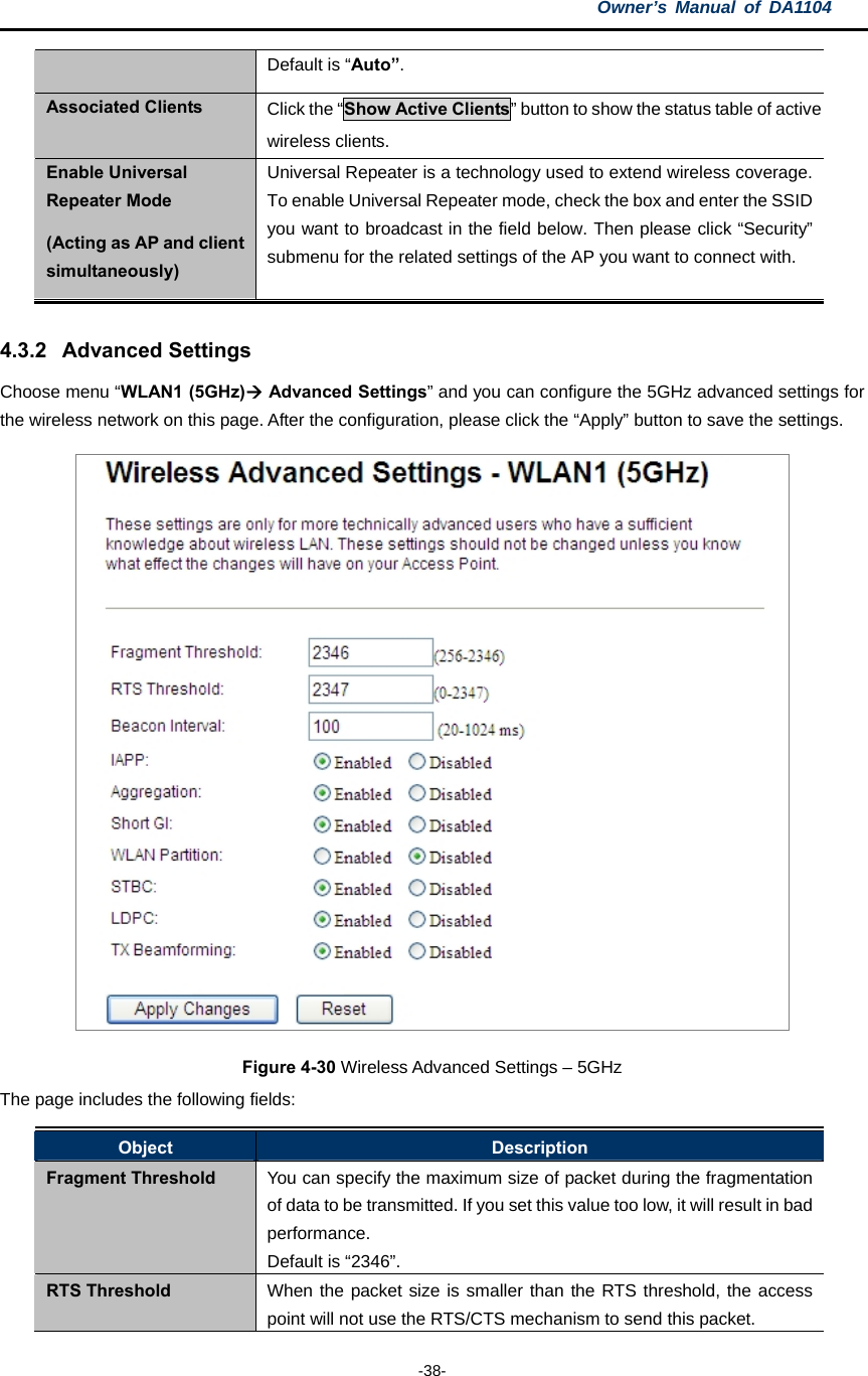
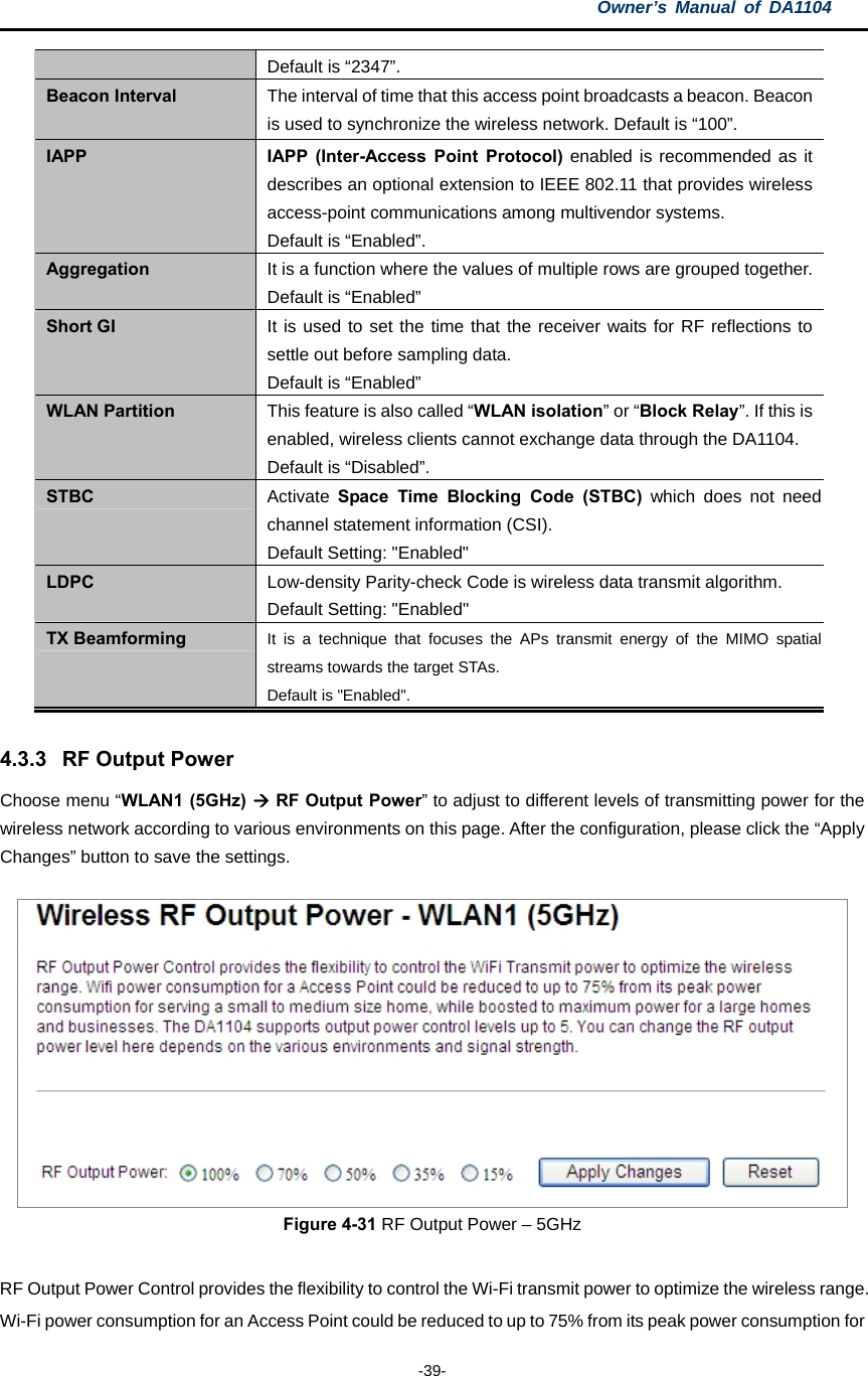
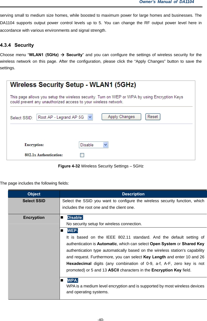
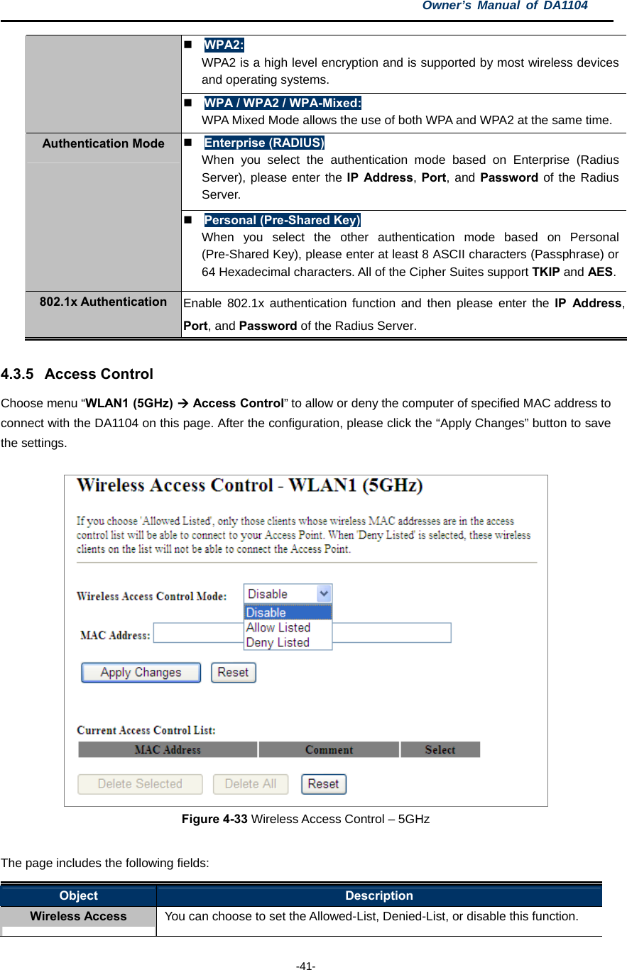
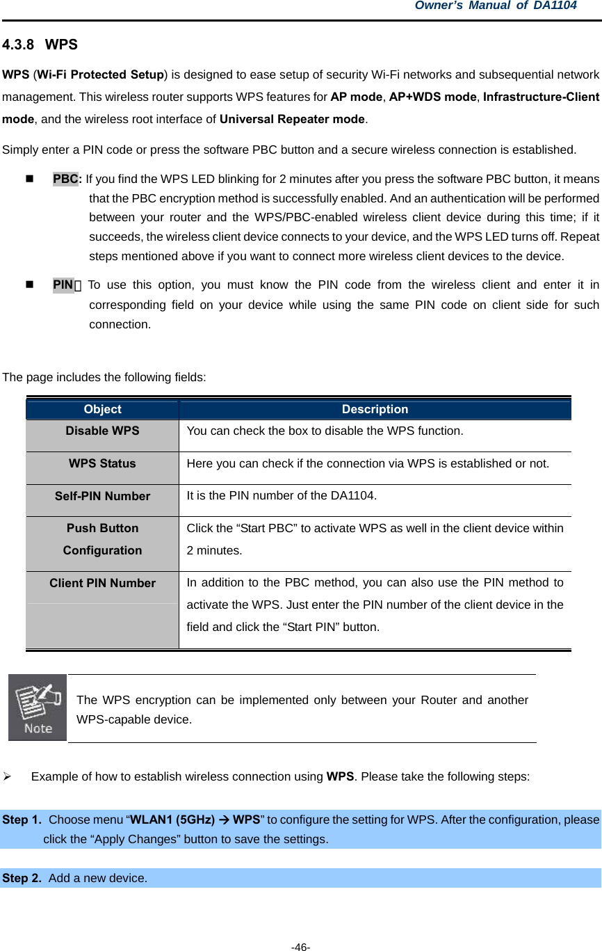
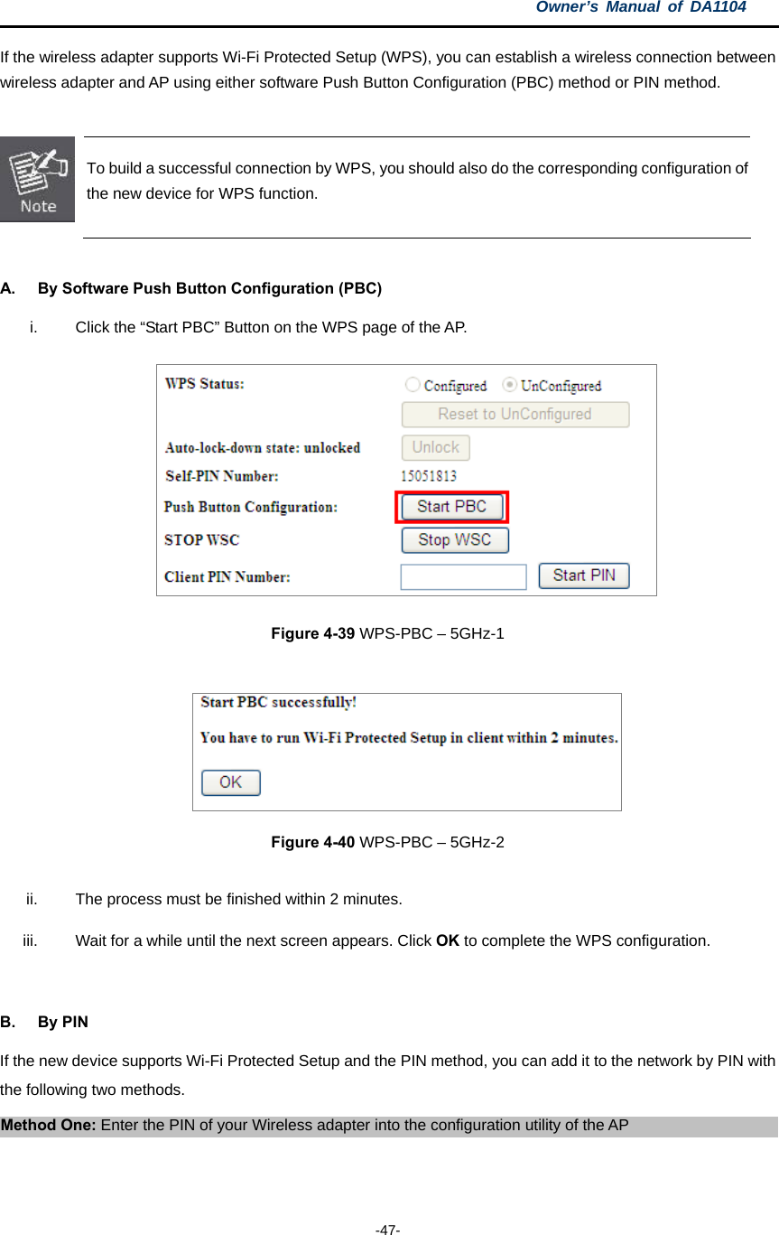
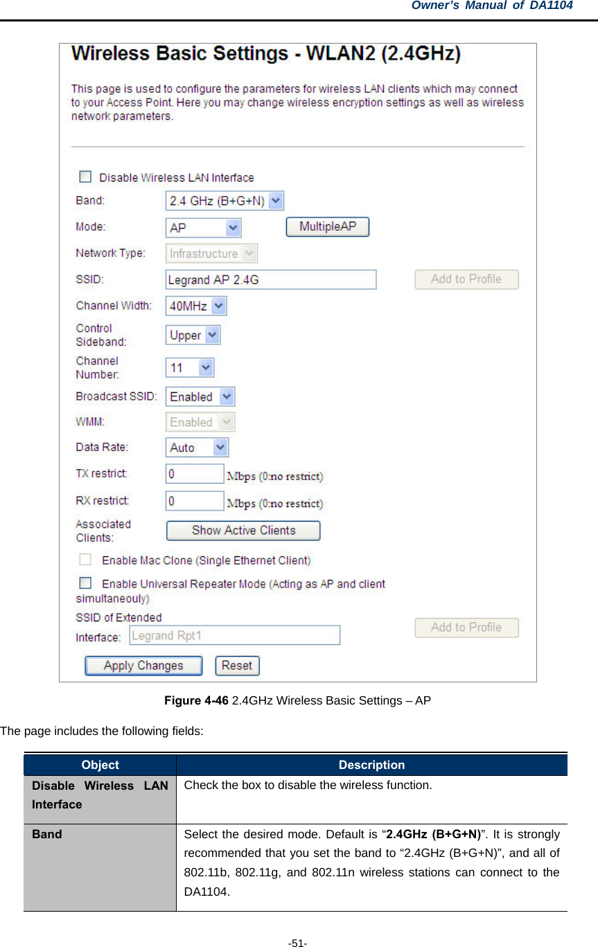
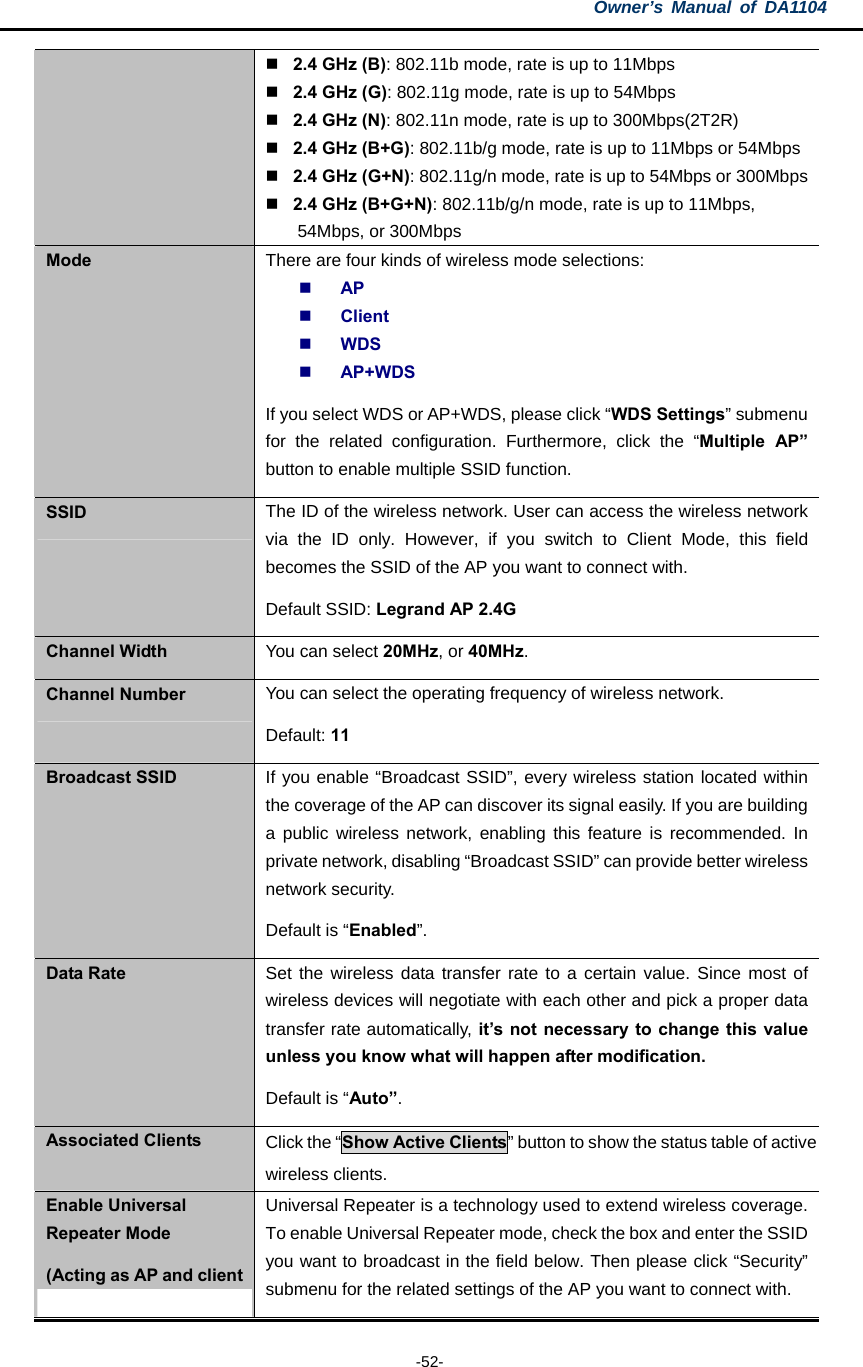
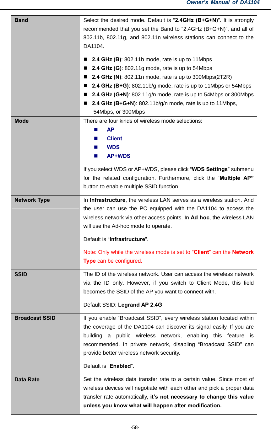
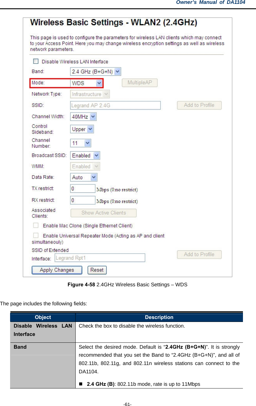
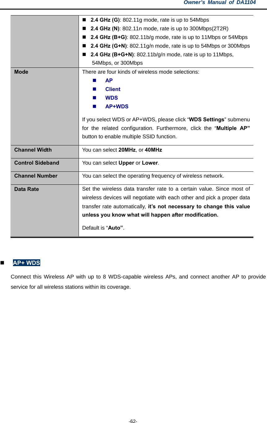
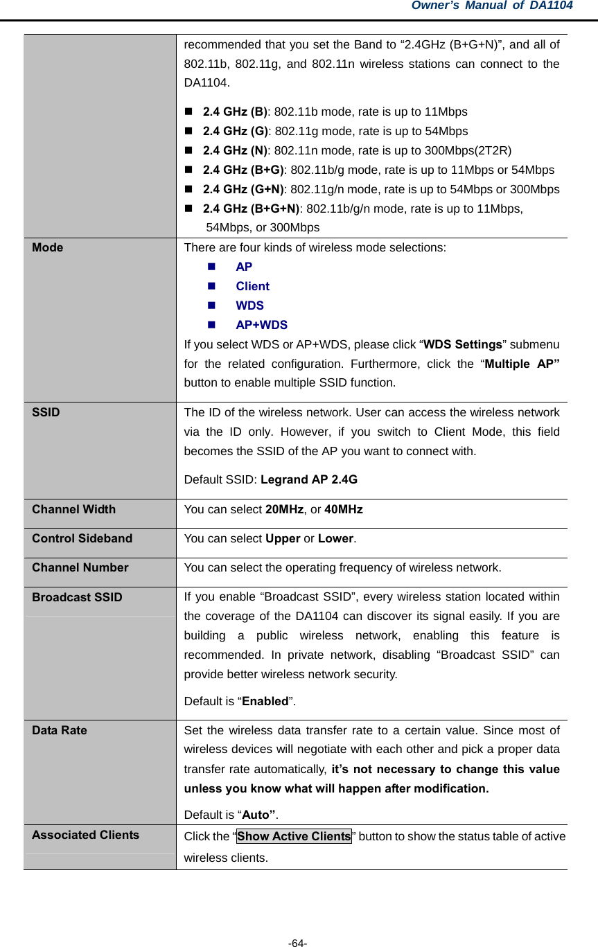
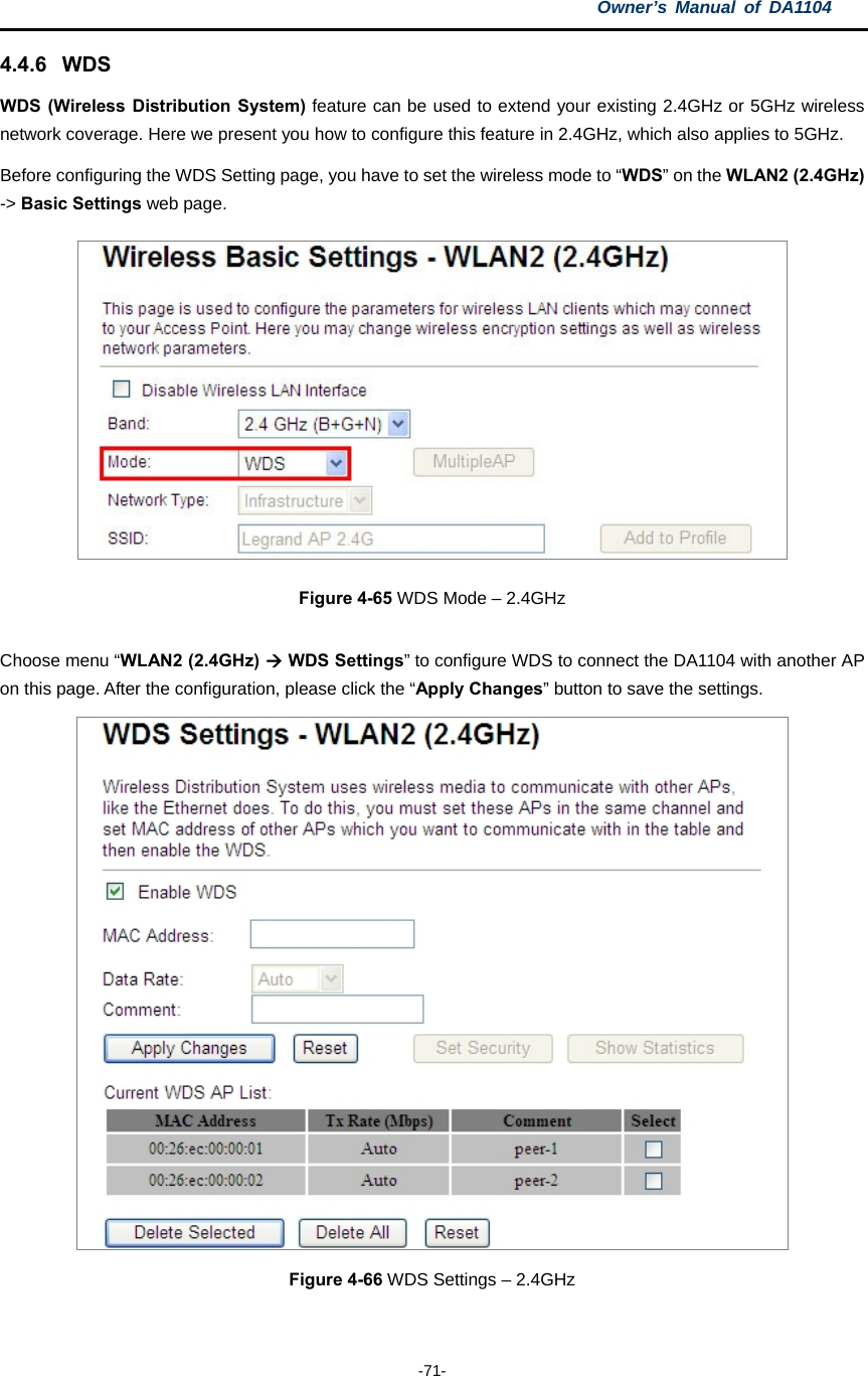
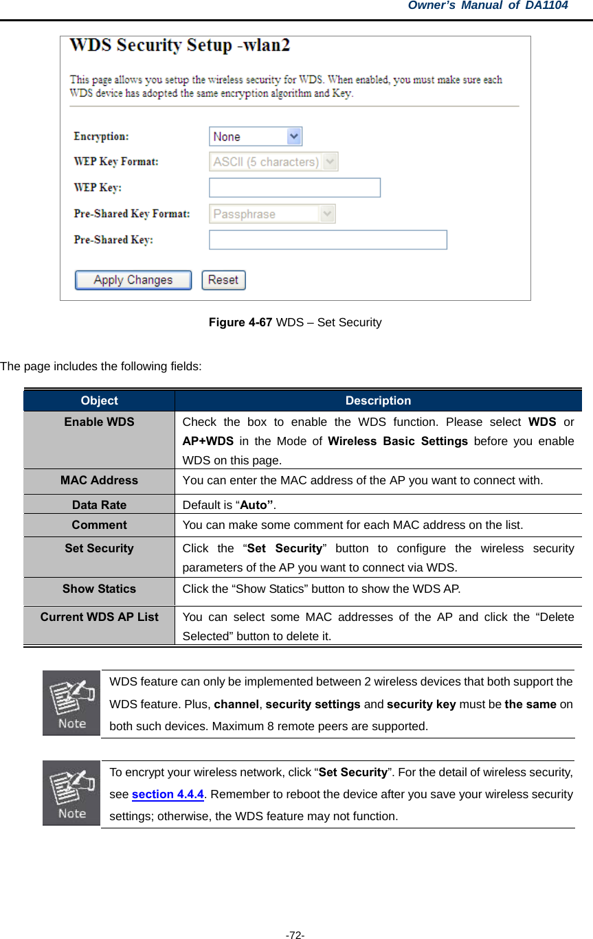
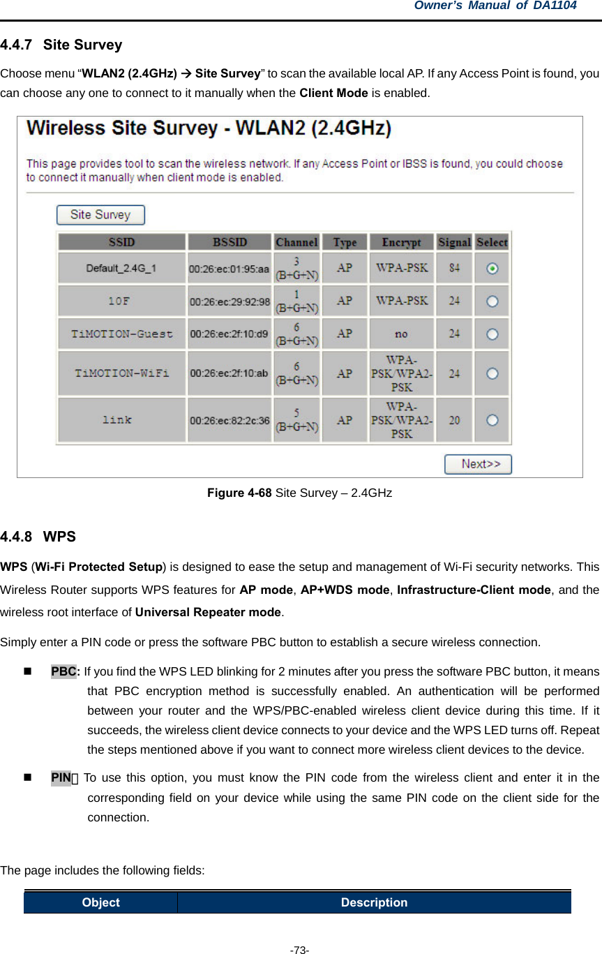
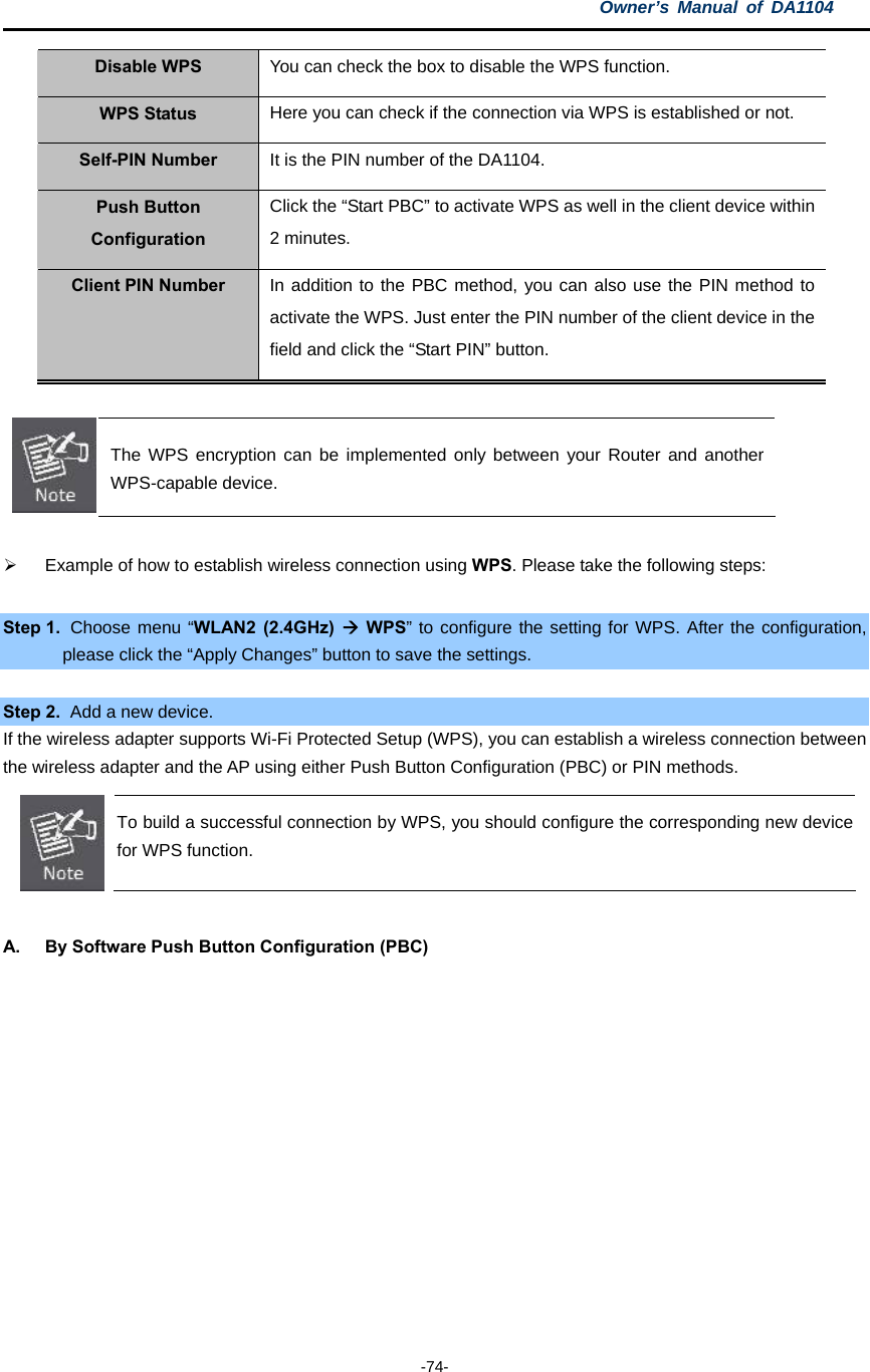
![Owner’s Manual of DA1104 -37- a region other than one of those specified in this field. If your country or region is not listed, please contact your local government agency for assistance. Band Select the desired mode. Default is “5GHz (A+N+AC)”. It is strongly recommended that you set the band to “5GHz (A+N+AC)”, and all of 802.11a, 802.11n, and 802.11ac wireless stations can connect to the DA1104. 5 GHz (A): 802.11a mode, rate is up to 54Mbps 5 GHz (N): 802.11n mode, rate is up to 300Mbps 5 GHz (AC): 802.11n mode, rate is up to 867Mbps (2T2R) 5 GHz (A+N): 802.11a/n mode, rate is up to 300Mbps 5 GHz (N+AC): 802.11n/ac mode, rate is up to 300Mbps or 867Mbps 5 GHz (A+N+AC): 802.11a/n/ac mode, rate is up to 54Mbps, 300Mbps, or 867Mbps Mode There are four kinds of wireless mode selections: AP Client WDS AP+WDS If you select WDS or AP+WDS, please click “WDS Settings” submenu for the related configuration. Furthermore, click the “Multiple AP” button to enable multiple SSID functions. SSID The ID of the wireless network. User can access the wireless network via its ID only. However, if you switch to Client Mode, this field becomes the SSID of the AP you want to connect with. Default SSID: Legrand AP 5G Channel Width You can select 20MHz, 40MHz or 80MHz. Control Sideband You can select Upper or Lower. Channel Number You can select the operating frequency of wireless network. Broadcast SSID If you enable “Broadcast SSID”, every wireless station located within the coverage of the DA1104 can discover its signal easily. If you are building a public wireless network, enabling this feature is recommended. In private network, disabling “Broadcast SSID” can provide better wireless network security. Default is “Enabled”. Data Rate Set the wireless data transfer rate to a certain value. Since most of wireless devices will negotiate with each other and pick a proper data transfer rate automatically, it’s not necessary to change this value unless you know what will happen after modification. 註解 [MSR2]: Where is this field?](https://usermanual.wiki/Pass-and-Seymour-d-b-a-Legrand/DA1104/User-Guide-2540229-Page-46.png)


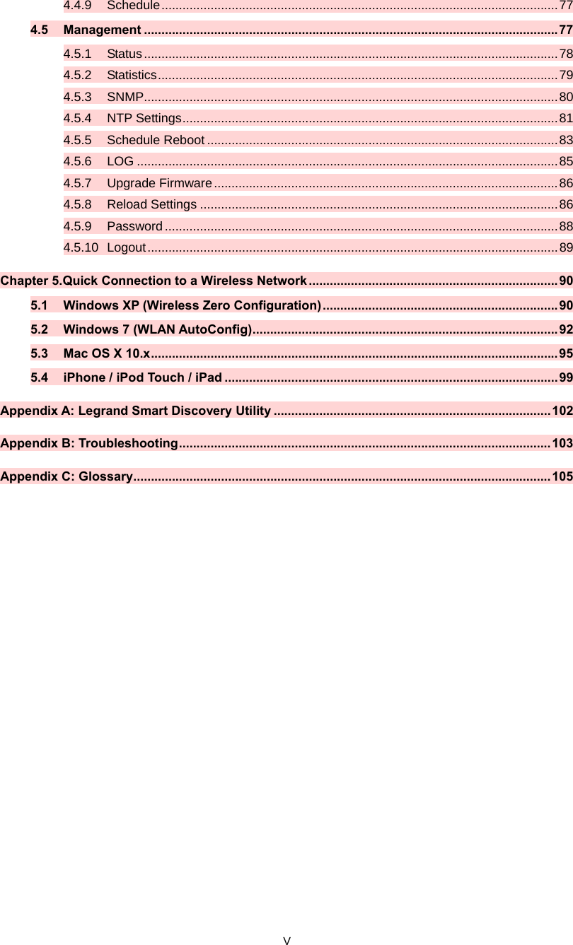
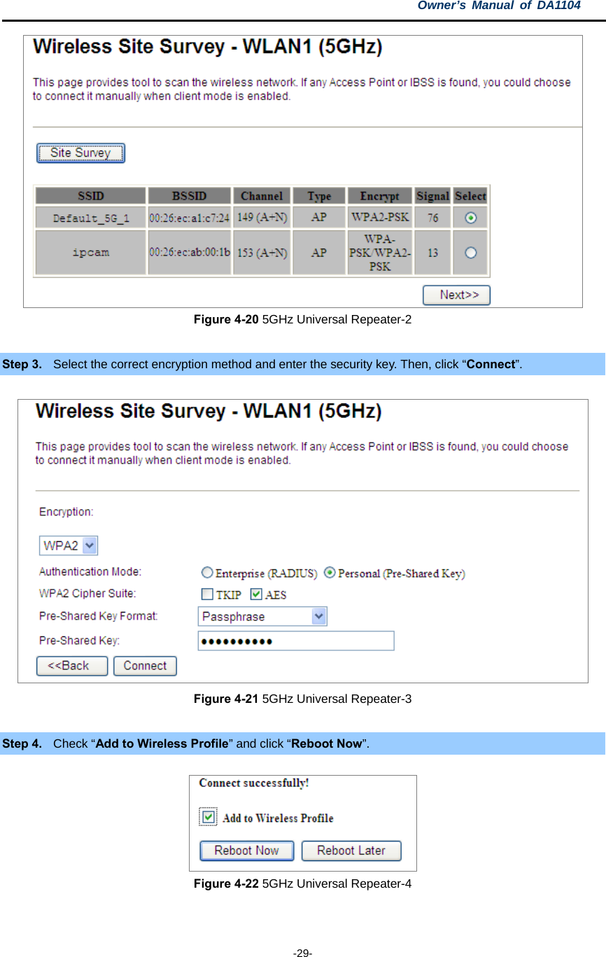
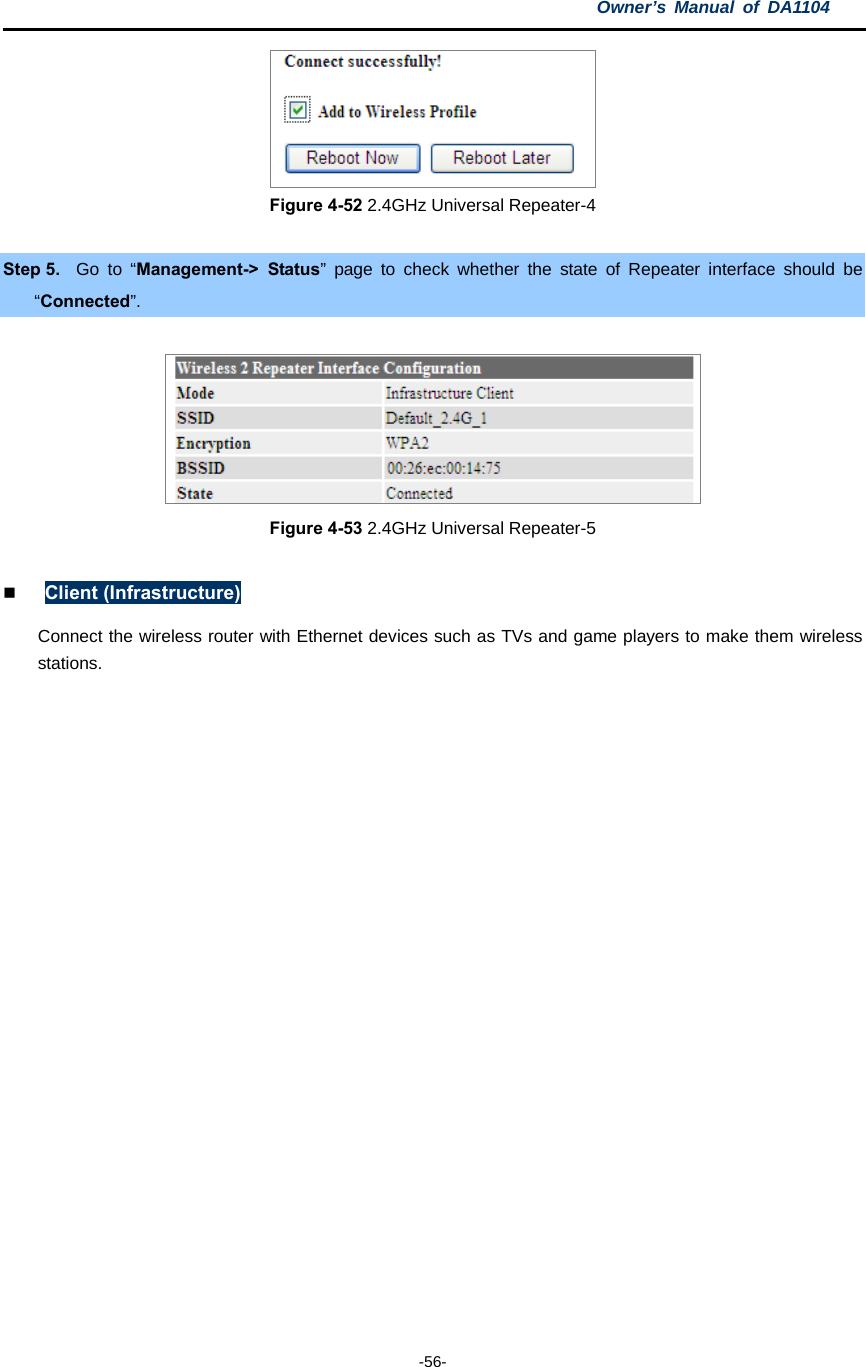
![Owner’s Manual of DA1104 -54- Universal Repeater This mode allows the AP with its own BSS to relay data to a root AP to which it is associated with WDS disabled. The wireless repeater relays the signal between its stations and the root AP for greater wireless range. Here is the example of how to configure Universal Repeater Mode.Use the following steps: To configure each wireless parameter, go to the “WLAN2 (2.4GHz) → Basic Settings” page. Step 1. Configure wireless mode to “AP” and then check “Enable Universal Repeater Mode (Acting as AP and client simultaneously)”. Click “Apply Changes” to take effect. Figure 4-49 2.4GHz Universal Repeater-1 Step 2. Go to 2.4GHz Site Survey page to find the root AP. Select the root AP that you want to repeat the signal, 註解 [MSR3]: simulaneously at the botttom is spelled wrong](https://usermanual.wiki/Pass-and-Seymour-d-b-a-Legrand/DA1104/User-Guide-2540229-Page-63.png)


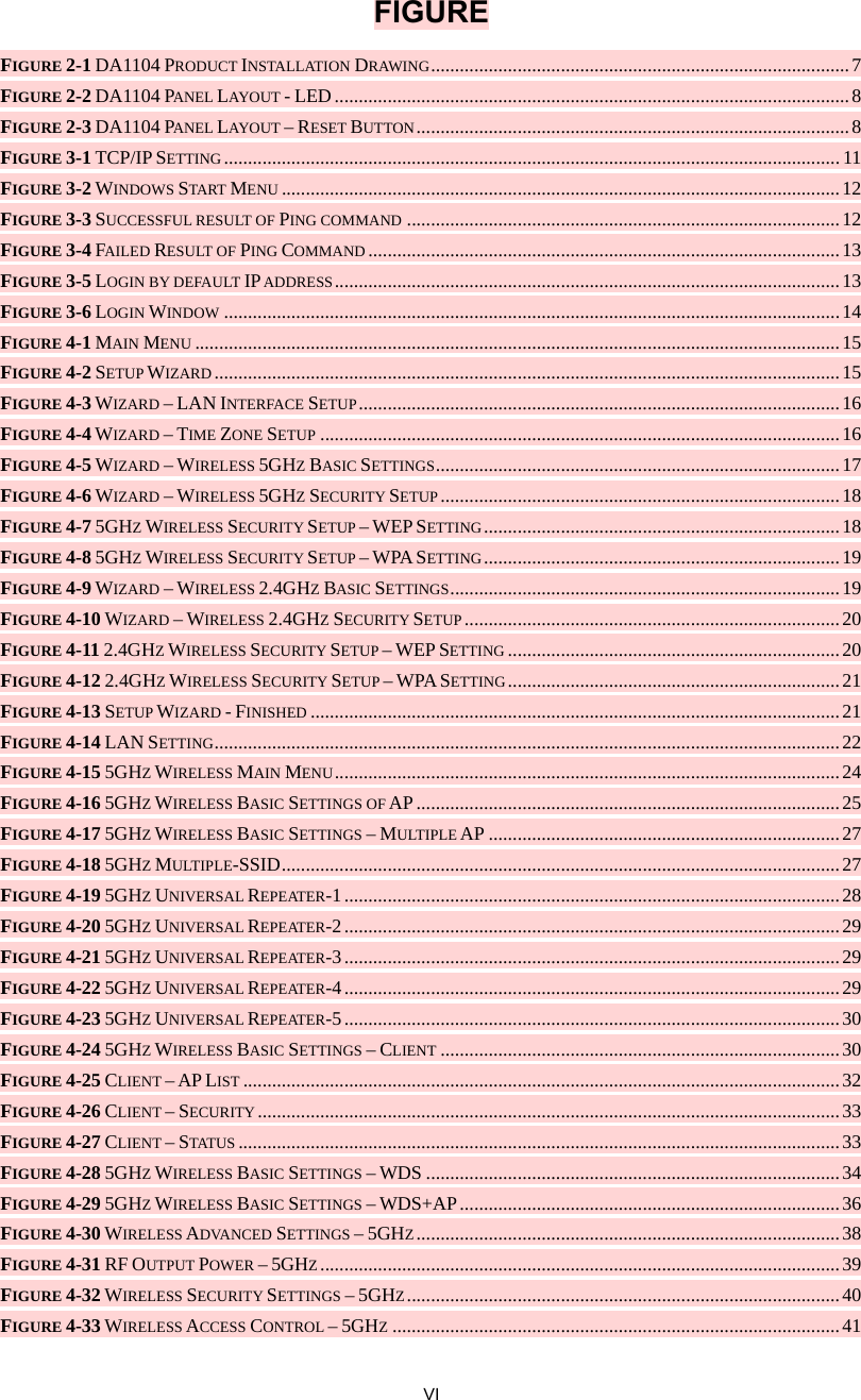
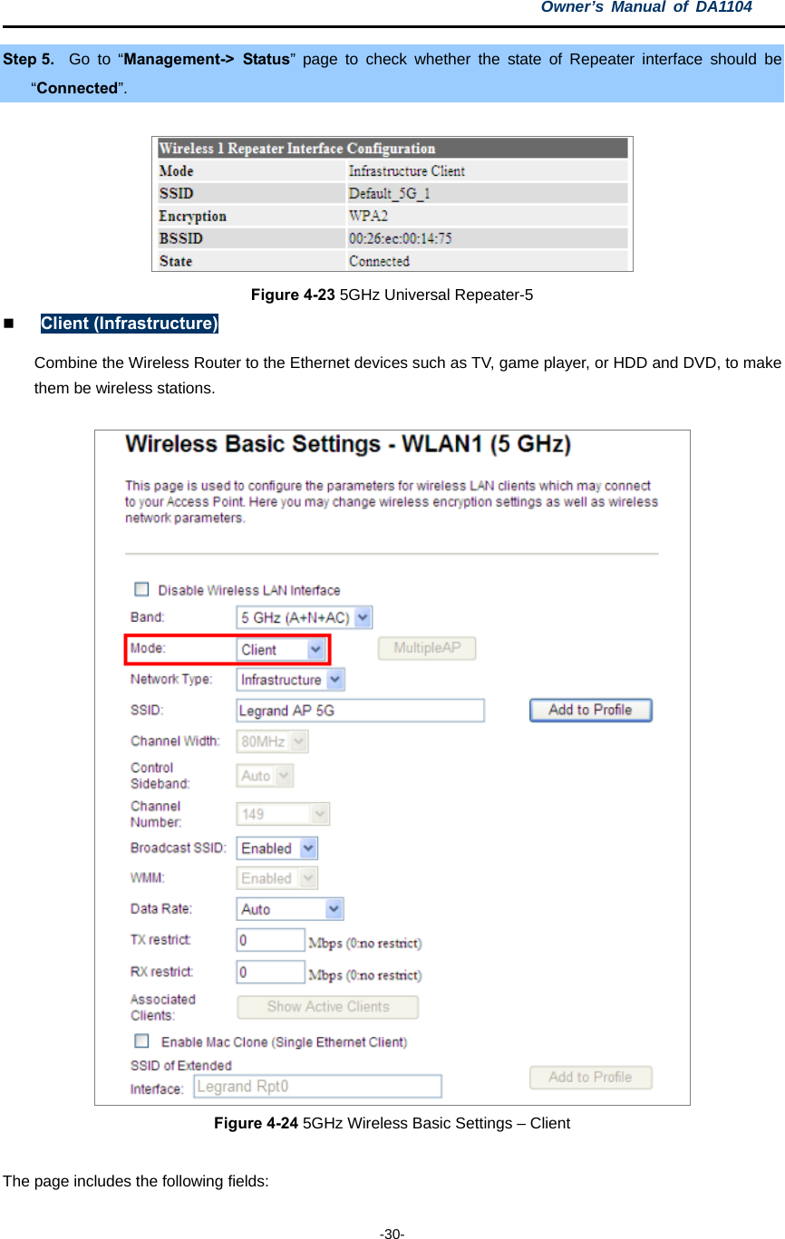
![Owner’s Manual of DA1104 -90- Chapter 5. Quick Connection to a Wireless Network In the following sections, the default SSID of the DA1104 is configured to “default”. 5.1 Windows XP (Wireless Zero Configuration) Step 1: Right-click on the wireless network icon displayed in the system tray Figure 5-1 System Tray – Wireless Network Icon Step 2: Select [View Available Wireless Networks] Step 3: Highlight and select the wireless network (SSID) to connect (1) Select SSID [default] (2) Click the [Connect] button Figure 5-2 Choose a wireless network](https://usermanual.wiki/Pass-and-Seymour-d-b-a-Legrand/DA1104/User-Guide-2540229-Page-99.png)
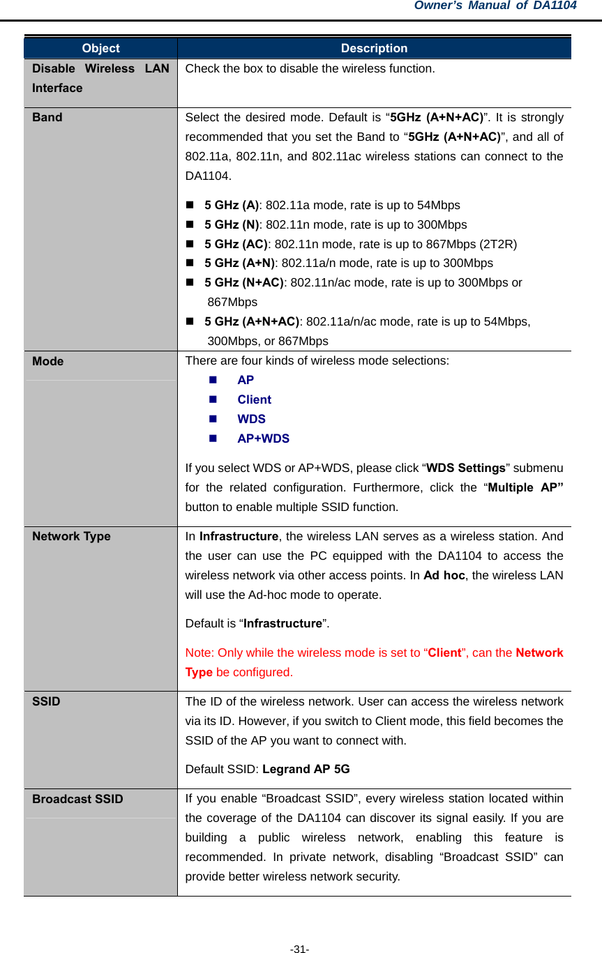
![Owner’s Manual of DA1104 -91- Step 4: Enter the encryption key of the Wireless AP (1) The Wireless Network Connection box will appear (2) Enter the encryption key that is configured in section 4.3.4 (3) Click the [Connect] button Figure 5-3 Enter the network key Step 5: Check if “Connected” is displayed Figure 5-4 Choose a wireless network -- Connected](https://usermanual.wiki/Pass-and-Seymour-d-b-a-Legrand/DA1104/User-Guide-2540229-Page-100.png)
![Owner’s Manual of DA1104 -92- Some laptops are equipped with a “Wireless ON/OFF” switch for the internal wireless LAN. Make sure the hardware wireless switch is switched to “ON” position. 5.2 Windows 7 (WLAN AutoConfig) WLAN AutoConfig service is built in to Windows 7 to detect and connect to wireless networks. This built-in wireless network connection tool is similar to the wireless zero configuration tool in Windows XP. Step 1: Right-click on the network icon displayed in the system tray Figure 5-5 Network icon Step 2: Highlight and select the wireless network (SSID) to connect (1) Select SSID [default] (2) Click the [Connect] button Figure 5-6 WLAN AutoConfig](https://usermanual.wiki/Pass-and-Seymour-d-b-a-Legrand/DA1104/User-Guide-2540229-Page-101.png)
![Owner’s Manual of DA1104 -93- If you will be connecting to this Wireless AP in the future, check [Connect automatically]. Step 4: Enter the encryption key of the Wireless AP (1) The Connect to a Network box will appear (2) Enter the encryption key that is configured in section 4.3.4 (3) Click the [OK] button Figure 5-7 Type the network key Figure 5-8 Connecting to a Network Step 5: Check if “Connected” is displayed](https://usermanual.wiki/Pass-and-Seymour-d-b-a-Legrand/DA1104/User-Guide-2540229-Page-102.png)

![Owner’s Manual of DA1104 -95- 5.3 Mac OS X 10.x In the following sections, the default SSID of the DA1104 is configured to “default”. Step 1: Right-click on the network icon displayed in the system tray The AirPort Network Connection menu will appear Figure 5-10 Mac OS – Network icon Step 2: Highlight and select the wireless network (SSID) to connect (1) Select and SSID [default] (2) Double-click on the selected SSID Figure 5-11 Highlight and select the wireless network Step 4: Enter the encryption key of the Wireless AP (1) Enter the encryption key that is configured in section 4.3.4 (2) Click the [OK] button](https://usermanual.wiki/Pass-and-Seymour-d-b-a-Legrand/DA1104/User-Guide-2540229-Page-104.png)
![Owner’s Manual of DA1104 -96- Figure 5-12 Enter the Password If you will be connecting to this Wireless AP in the future, check [Remember this network]. Step 5: Check if the AirPort is connected to the selected wireless network. If “Yes”, then there will be a “check” symbol in the front of the SSID. Figure 5-13 Connected to the network](https://usermanual.wiki/Pass-and-Seymour-d-b-a-Legrand/DA1104/User-Guide-2540229-Page-105.png)
![Owner’s Manual of DA1104 -97- There is another way to configure the MAC OS X Wireless settings: Step 1: Click and open the [System Preferences] by going to Apple > System Preference or Applications Figure 5-14 System Preferences Step 2: Open Network Preference by clicking on the [Network] icon Figure 5-15 System Preferences -- Network](https://usermanual.wiki/Pass-and-Seymour-d-b-a-Legrand/DA1104/User-Guide-2540229-Page-106.png)
![Owner’s Manual of DA1104 -98- Step 3: Check Wi-Fi setting and select the available wireless network (1) Choose the AirPort on the left-menu (make sure it is ON) (2) Select Network Name [default] here If this is the first time to connect to the Wireless AP, it should show “Not network selected”. Figure 5-16 Select the Wireless Network](https://usermanual.wiki/Pass-and-Seymour-d-b-a-Legrand/DA1104/User-Guide-2540229-Page-107.png)
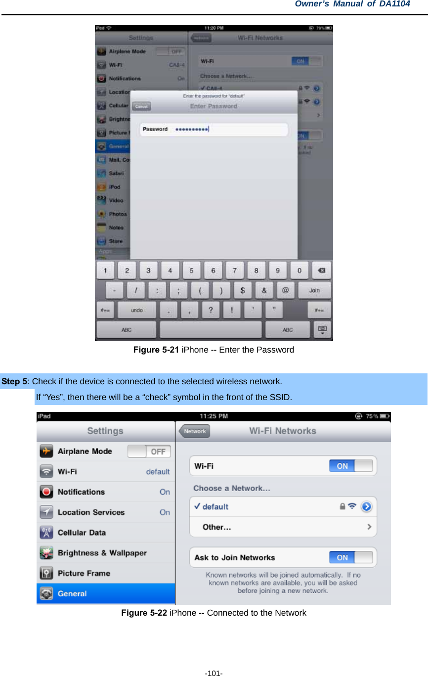
![Owner’s Manual of DA1104 -99- 5.4 iPhone / iPod Touch / iPad In the following sections, the default SSID of the DA1104 is configured to “default”. Step 1: Tap the [Settings] icon displayed in the home screen Figure 5-17 iPhone – Settings icon Step 2: Check Wi-Fi setting and select the available wireless network (3) Tap [General] \ [Network] (4) Tap [Wi-Fi] If this is the first time to connect to the Wireless AP, it should show “Not Connected”. Figure 5-18 Wi-Fi Setting](https://usermanual.wiki/Pass-and-Seymour-d-b-a-Legrand/DA1104/User-Guide-2540229-Page-108.png)
![Owner’s Manual of DA1104 -100- Figure 5-19 Wi-Fi Setting – Not Connected Step 3: Tap the target wireless network (SSID) in “Choose a Network…” (1) Turn on Wi-Fi by tapping “Wi-Fi” (2) Select SSID [default] Figure 5-20 Turn on Wi-Fi Step 4: Enter the encryption key of the Wireless AP (1) The password input screen will be displayed (2) Enter the encryption key that is configured in section 4.3.4 (3) Tap the [Join] button](https://usermanual.wiki/Pass-and-Seymour-d-b-a-Legrand/DA1104/User-Guide-2540229-Page-109.png)
![Owner’s Manual of DA1104 -105- Appendix C: Glossary 802.11ac - 802.11ac is a wireless networking standard in the 802.11 family (which is marketed under the brand name Wi-Fi), developed in the IEEE Standards Association process, providing high-throughput wireless local area networks (WLANs) on the 5 GHz band. 802.11n - 802.11n builds upon previous 802.11 standards by adding MIMO (multiple-input multiple-output). MIMO uses multiple transmitter and receiver antennas to allow for increased data throughput via spatial multiplexing and increased range by exploiting the spatial diversity, perhaps through coding schemes like Alamouti coding. The Enhanced Wireless Consortium (EWC) [3] was formed to help accelerate the IEEE 802.11n development process and promote a technology specification for interoperability of next-generation wireless local area networking (WLAN) products. 802.11a - 802.11a was an amendment to the IEEE 802.11 wireless local network specifications that defined requirements for an orthogonal frequency division multiplexing (OFDM) communication system. It was originally designed to support wireless communication in the unlicensed national information infrastructure (U-NII) bands (in the 5–6 GHz frequency range) as regulated in the United States by the Code of Federal Regulations, Title 47, Section 15.407. 802.11b - The 802.11b standard specifies a wireless networking at 11 Mbps using direct-sequence spread-spectrum (DSSS) technology and operating in the unlicensed radio spectrum at 2.4GHz, and WEP encryption for security. 802.11b networks are also referred to as Wi-Fi networks. 802.11g - specification for wireless networking at 54 Mbps using direct-sequence spread-spectrum (DSSS) technology, using OFDM modulation and operating in the unlicensed radio spectrum at 2.4GHz, and backward compatibility with IEEE 802.11b devices, and WEP encryption for security. DDNS (Dynamic Domain Name System) - The capability of assigning a fixed host and domain name to a dynamic Internet IP Address. DHCP (Dynamic Host Configuration Protocol) - A protocol that automatically configure the TCP/IP parameters for the all the PC(s) that are connected to a DHCP server. DMZ (Demilitarized Zone) - A Demilitarized Zone allows one local host to be exposed to the Internet for a special-purpose service such as Internet gaming or videoconferencing. DNS (Domain Name System) - An Internet Service that translates the names of websites into IP addresses. Domain Name - A descriptive name for an address or group of addresses on the Internet. DSL (Digital Subscriber Line) - A technology that allows data to be sent or received over existing traditional phone lines. ISP (Internet Service Provider) - A company that provides access to the Internet.](https://usermanual.wiki/Pass-and-Seymour-d-b-a-Legrand/DA1104/User-Guide-2540229-Page-114.png)
