Pass and Seymour d b a Legrand DA2131-V1A Outdoor 802.11n Wireless Access Point User Manual Selective Call System User s Guide
Pass & Seymour, Inc. d/b/a Legrand Outdoor 802.11n Wireless Access Point Selective Call System User s Guide
UserManual.wiki
>
Pass and Seymour d b a Legrand
>
DA2131 V1A User Manual
Users Manual
Navigation menu
Upload a User Manual
Namespaces
Wiki Guide
HTML
PDF
Info
Views
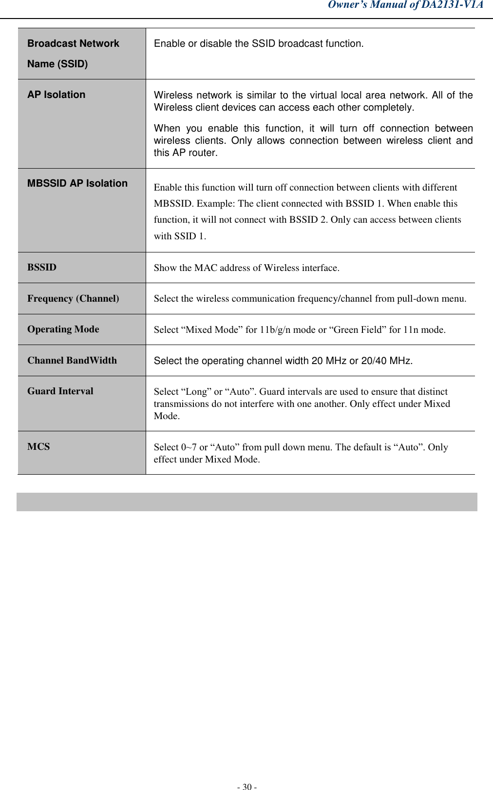
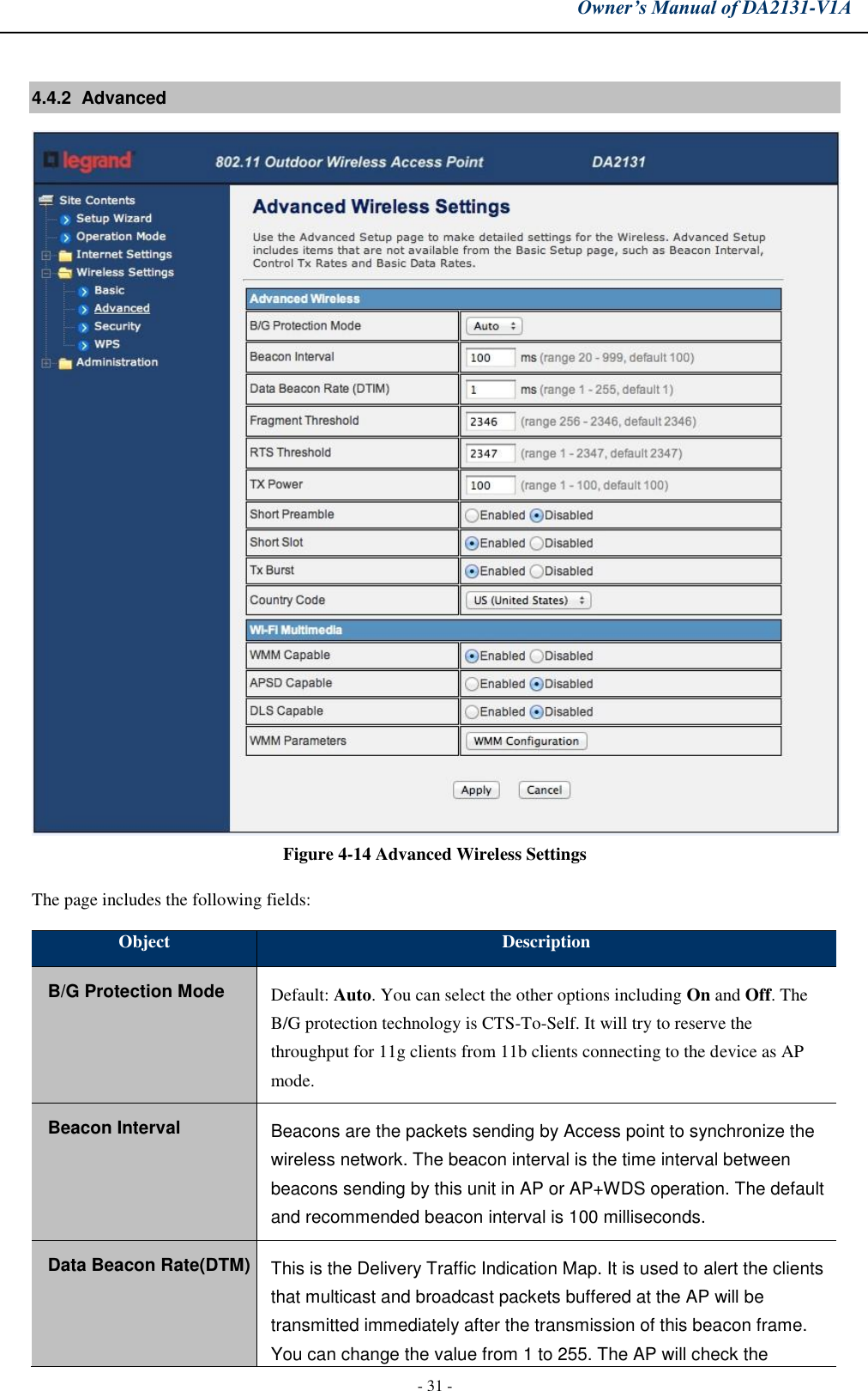
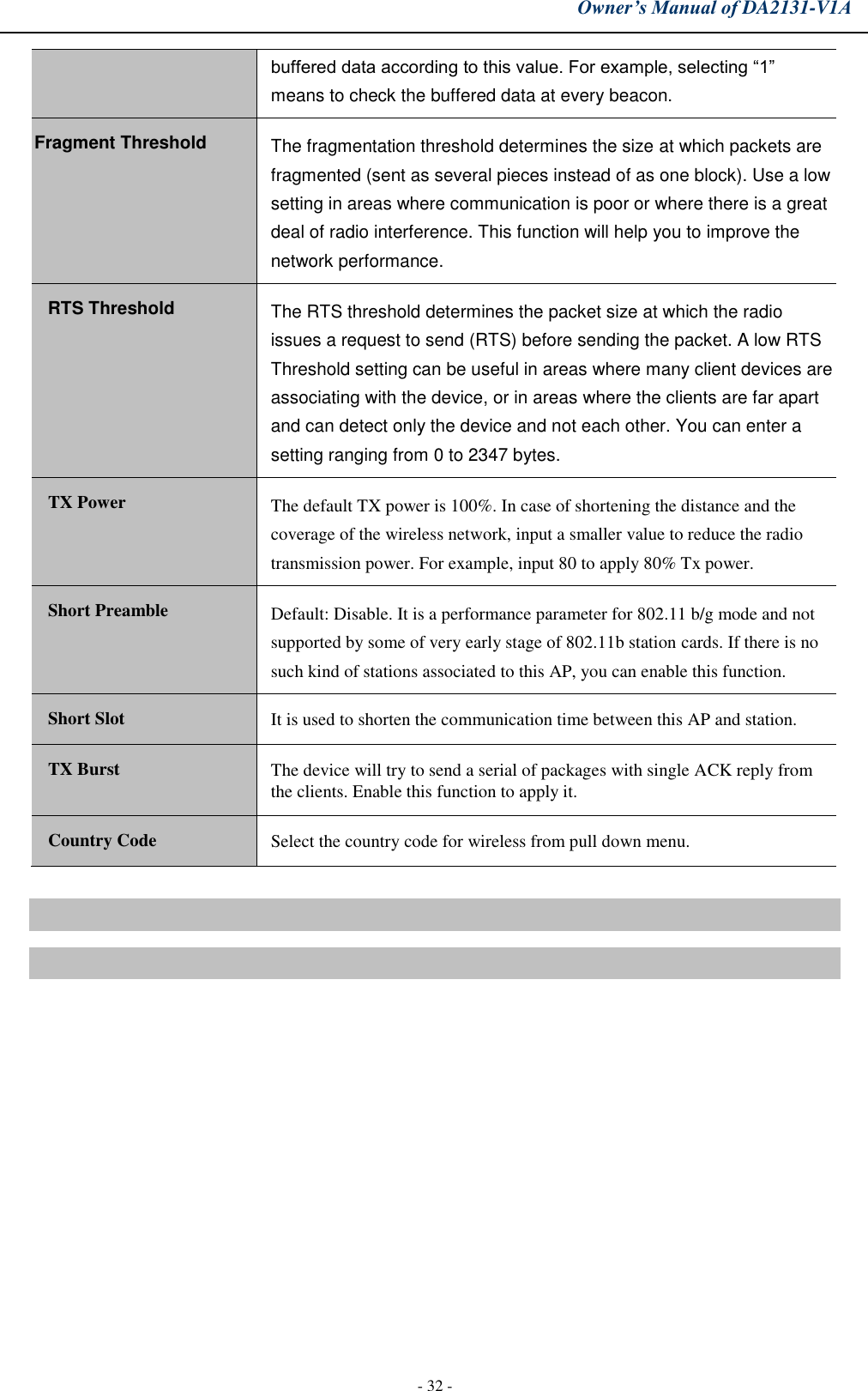
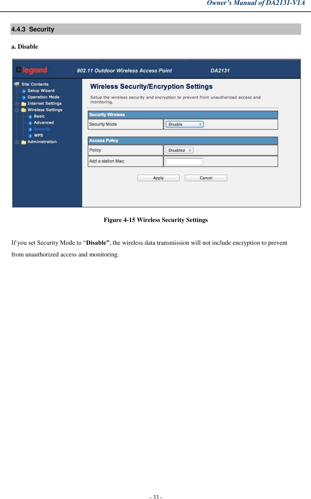
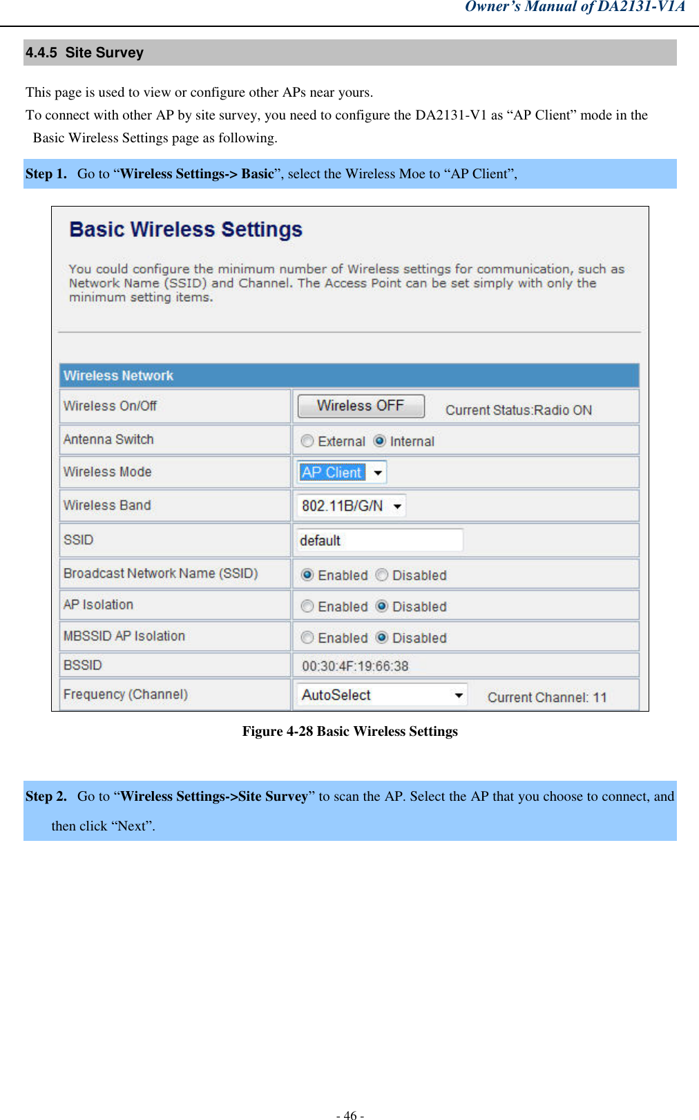
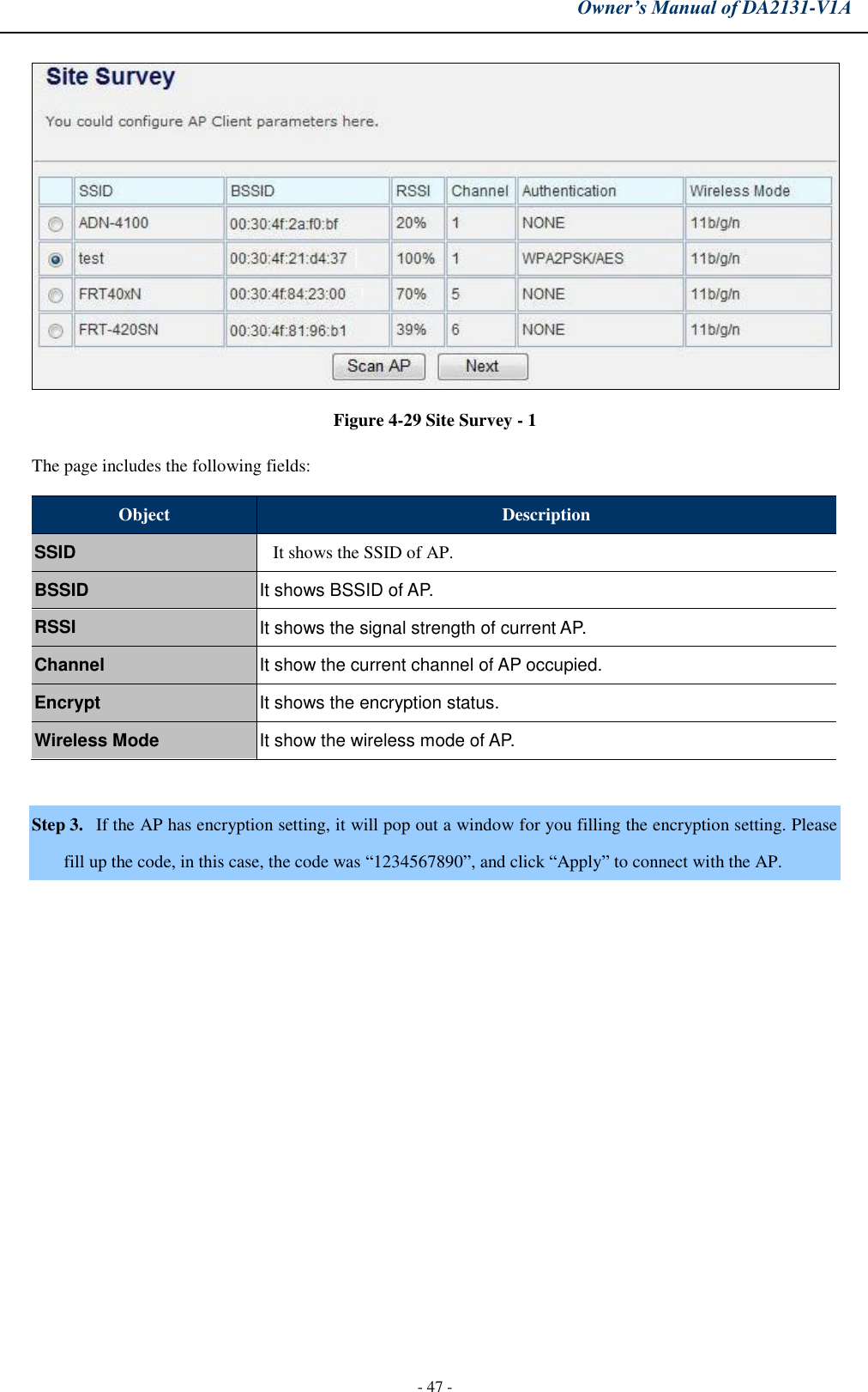
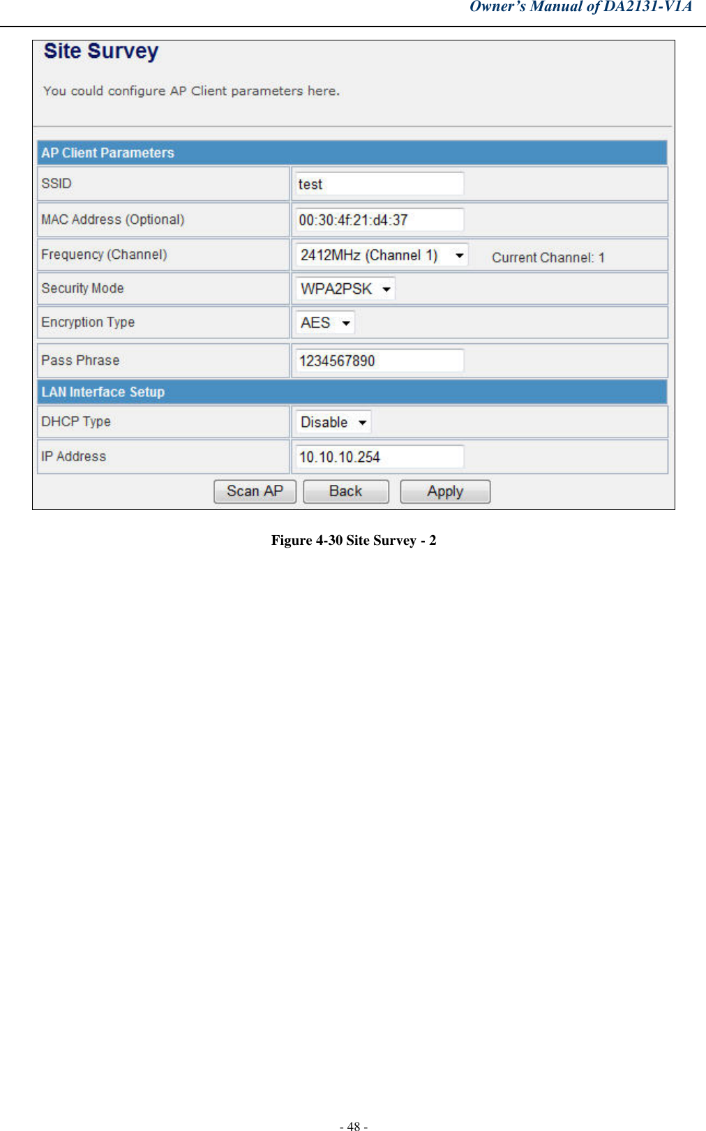
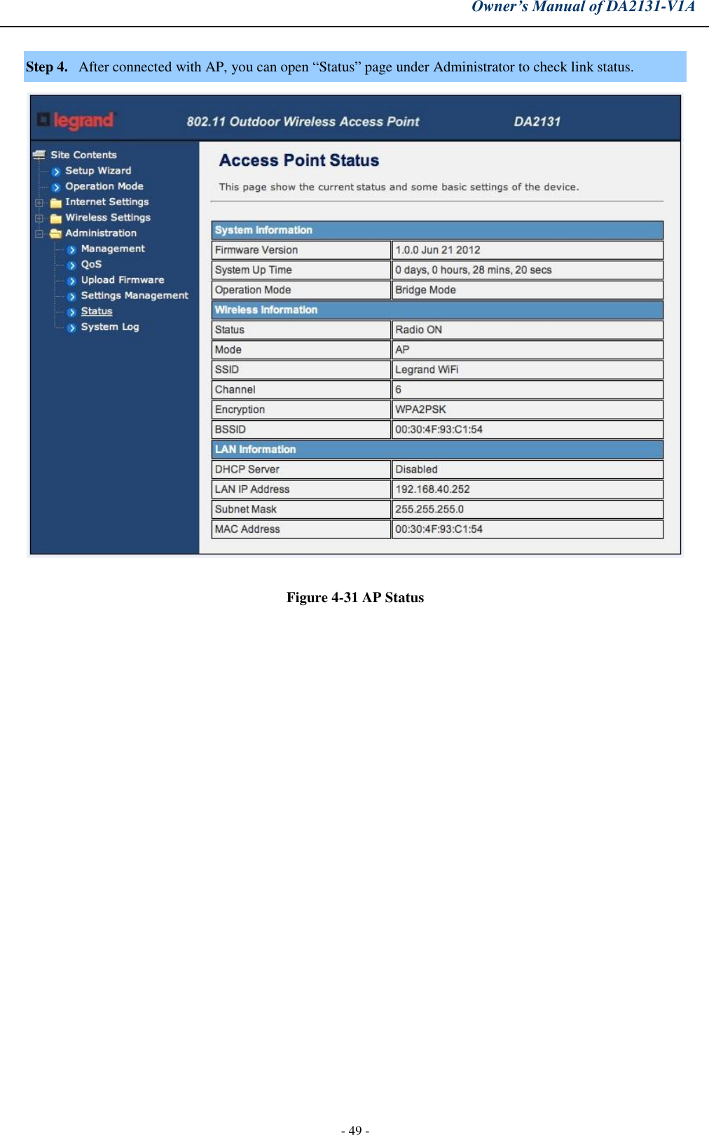
User Manual
Discussion / Help
Navigation
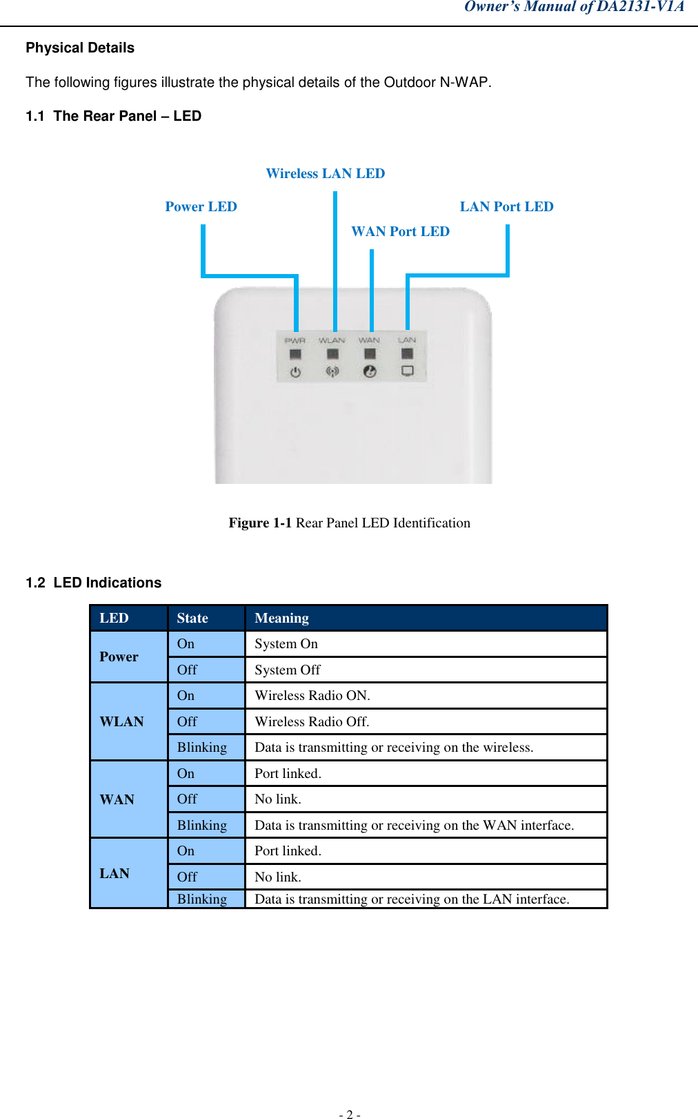
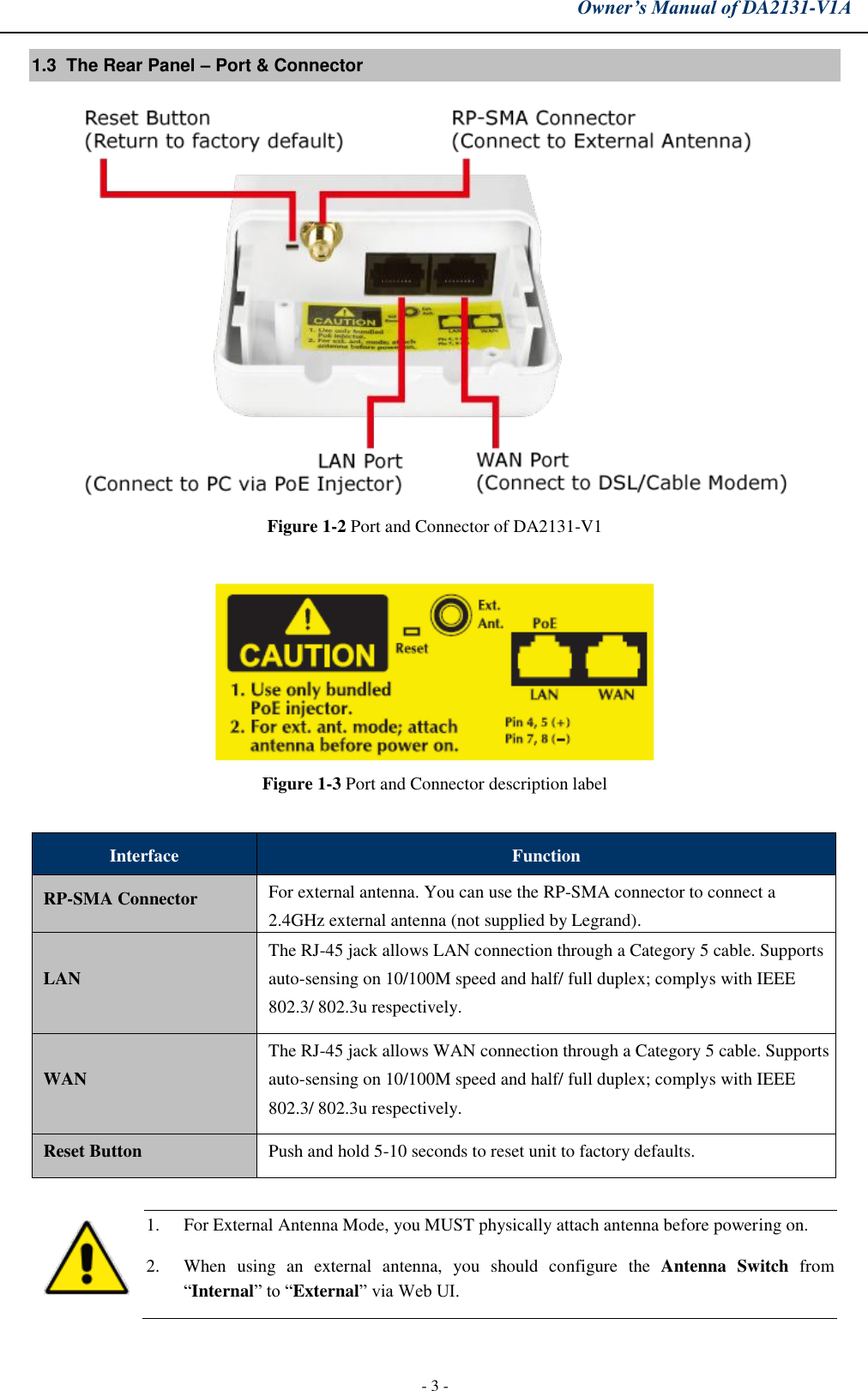
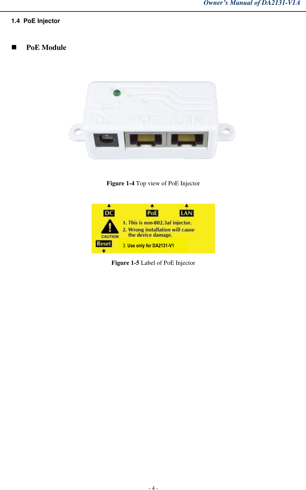
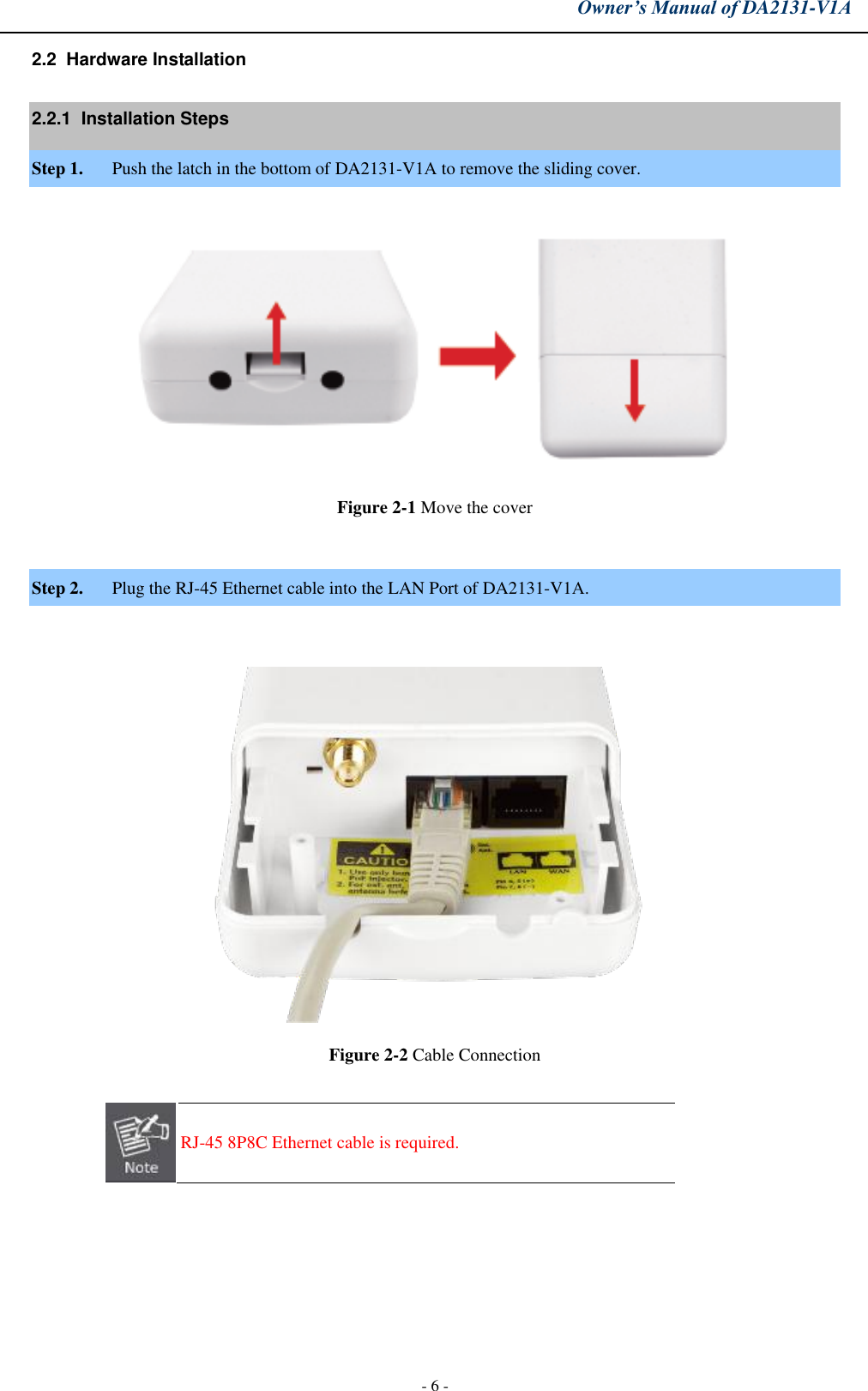
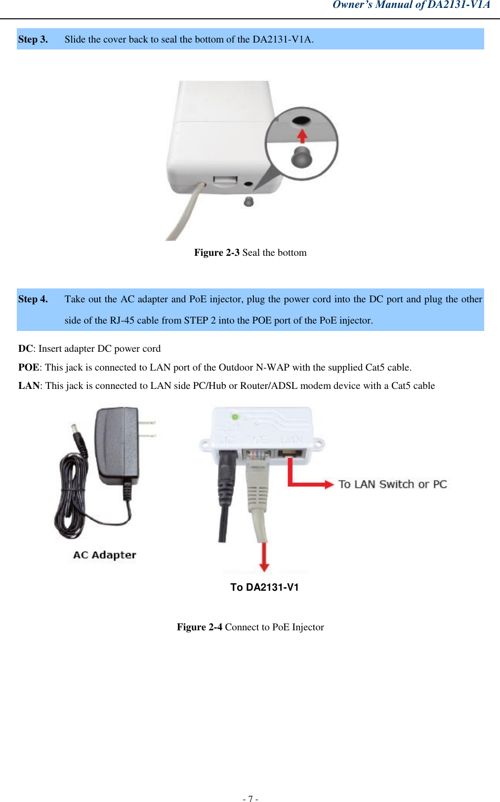
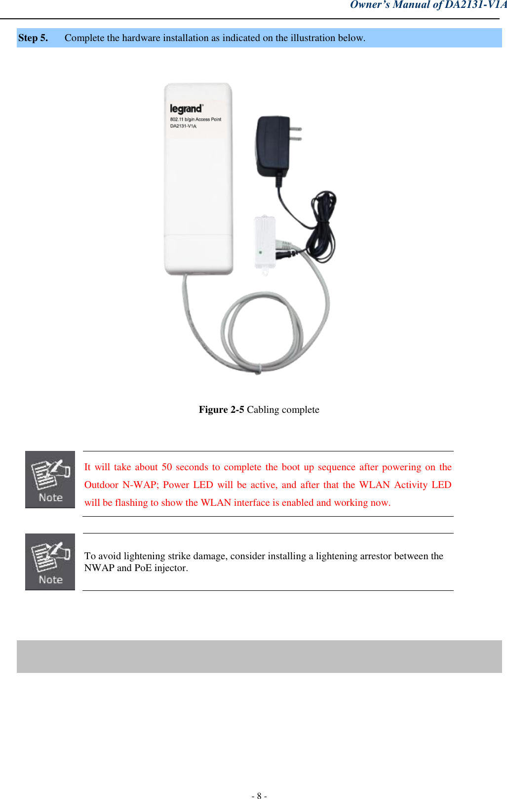
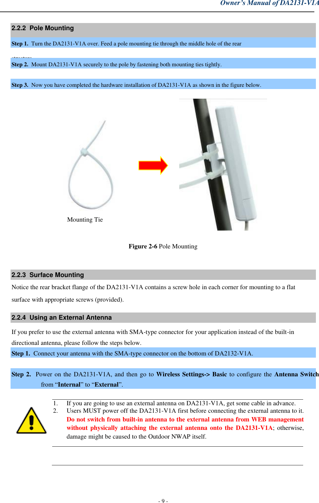
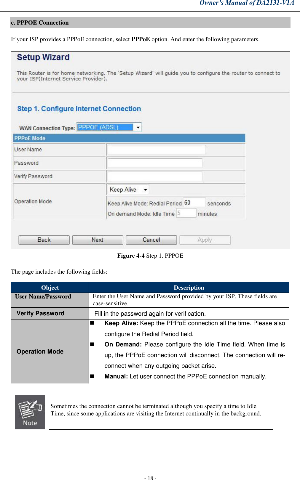
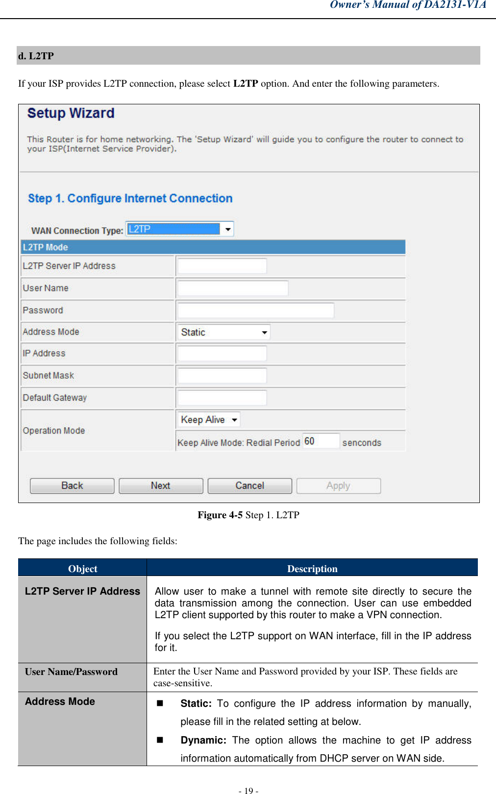
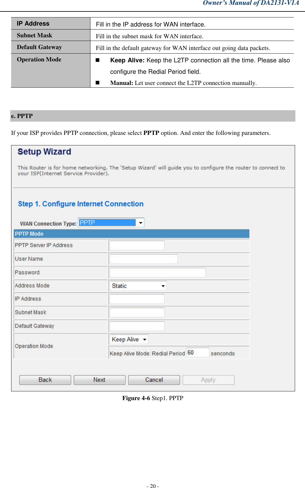
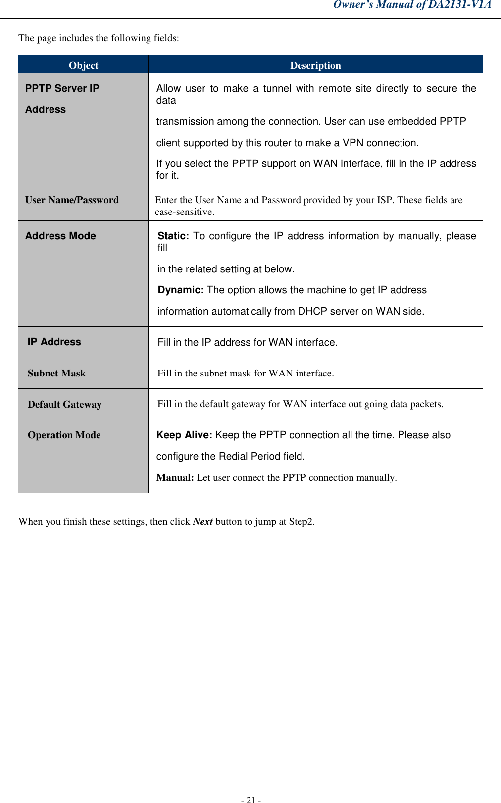
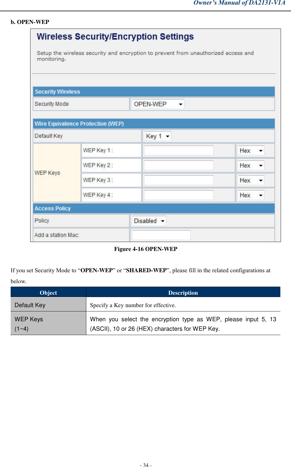
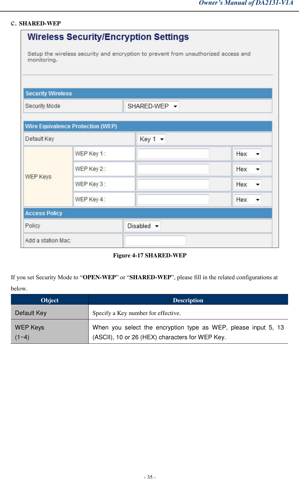
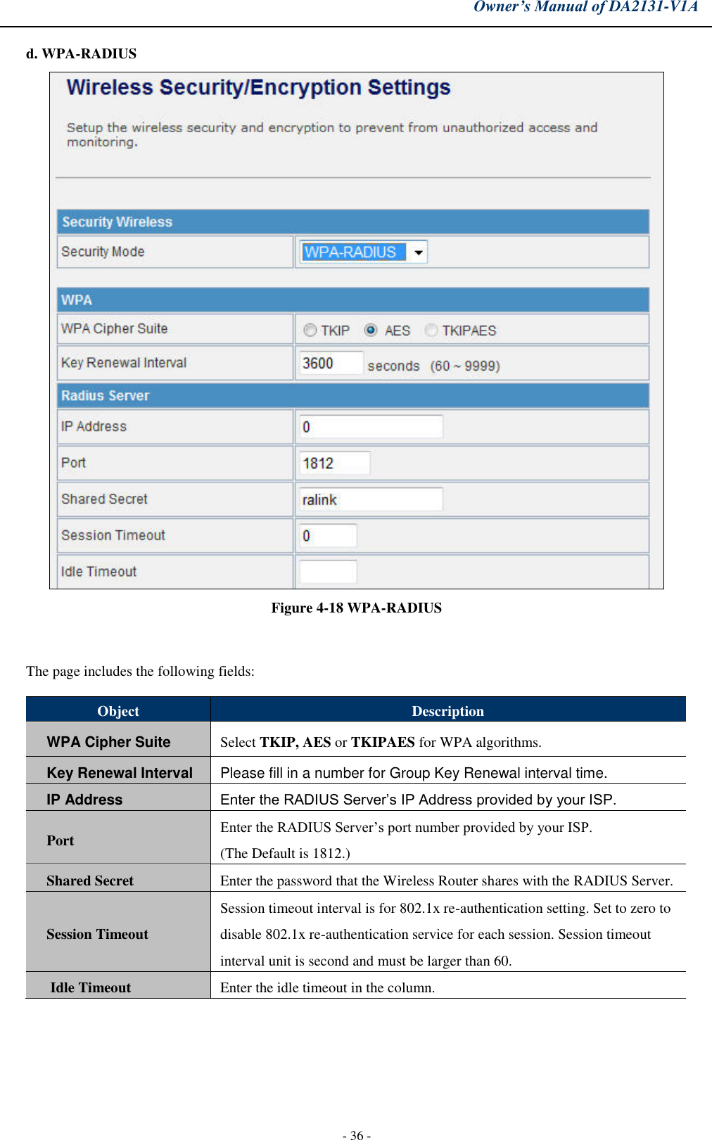
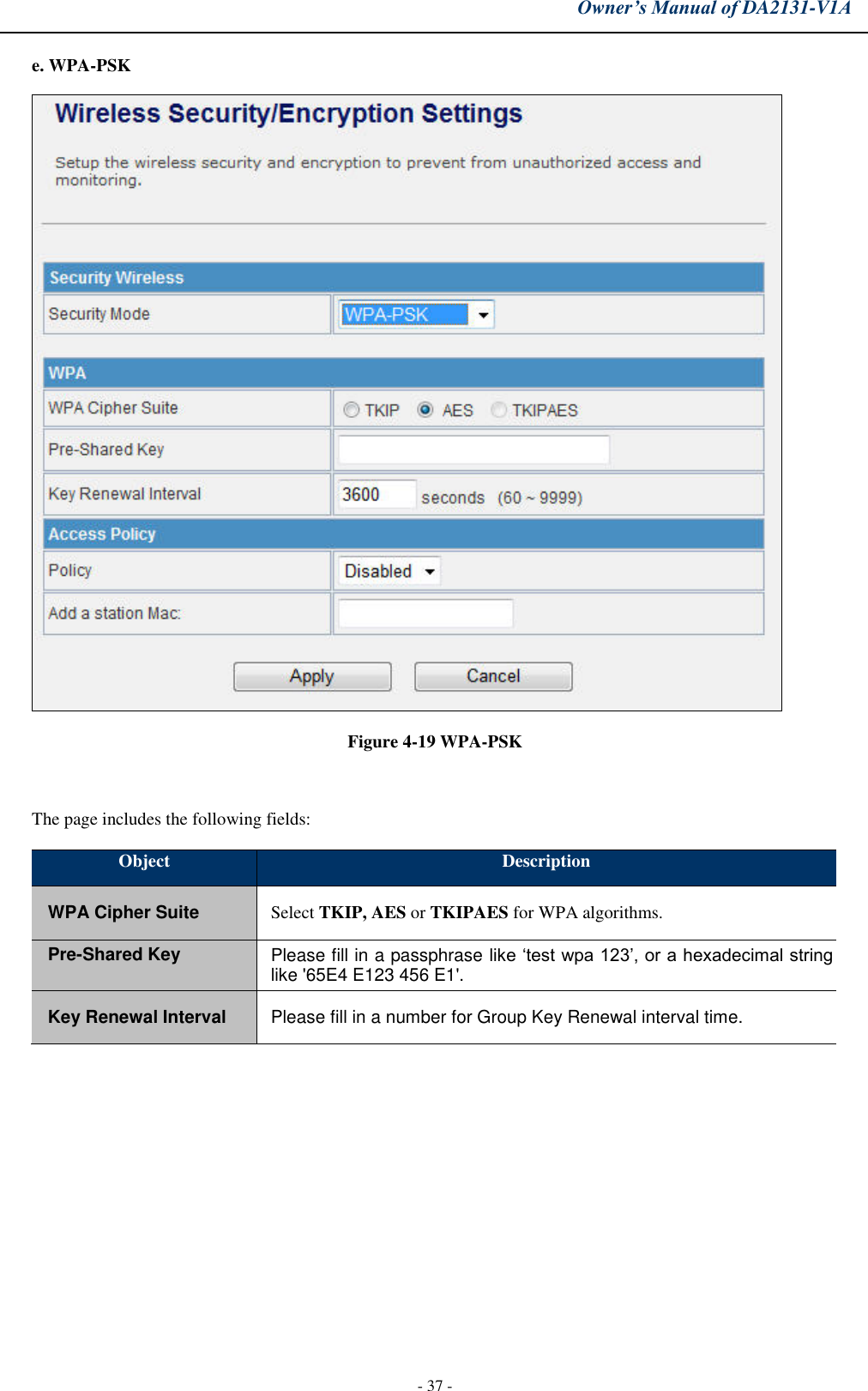
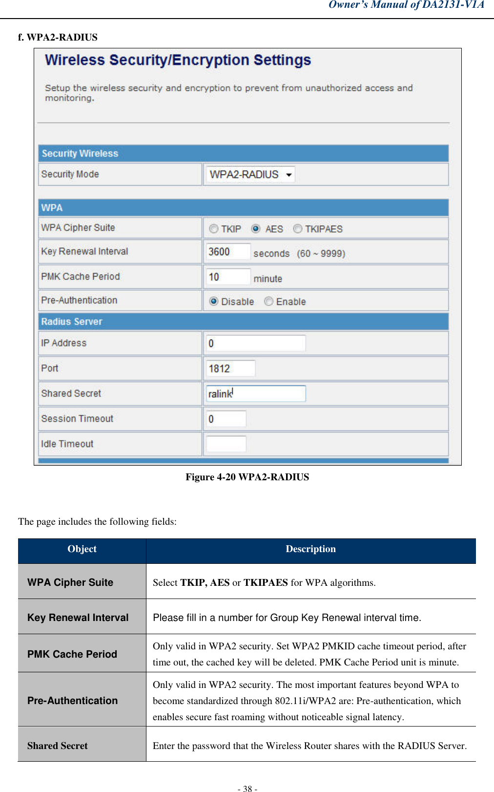
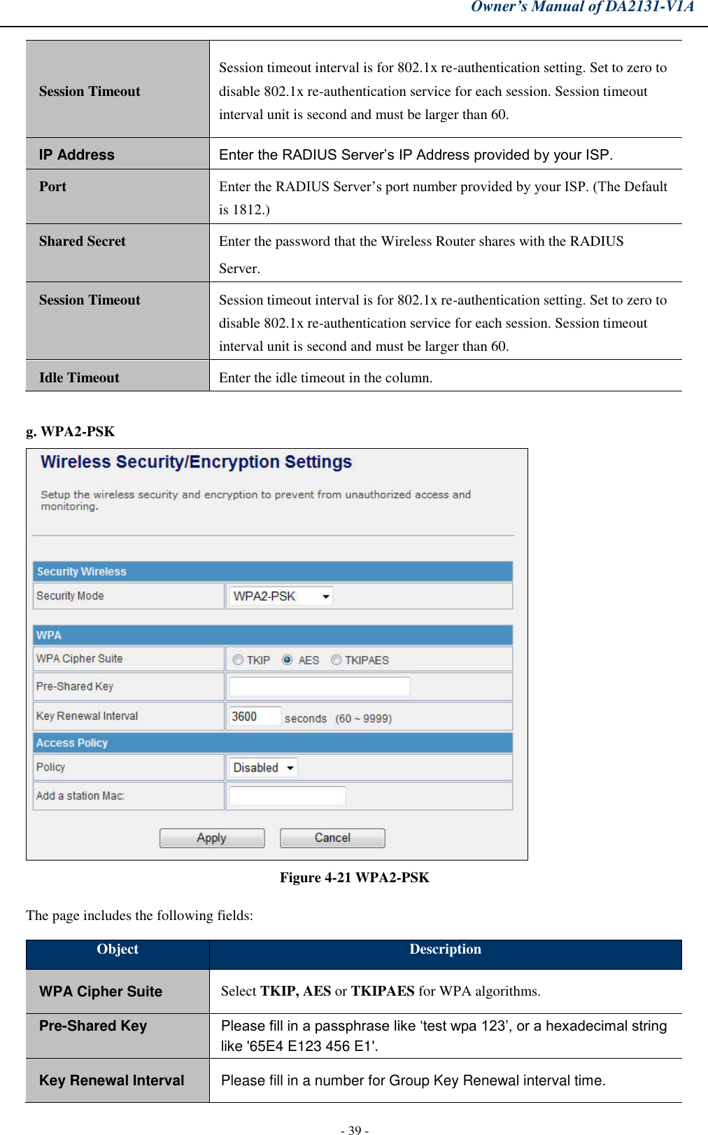
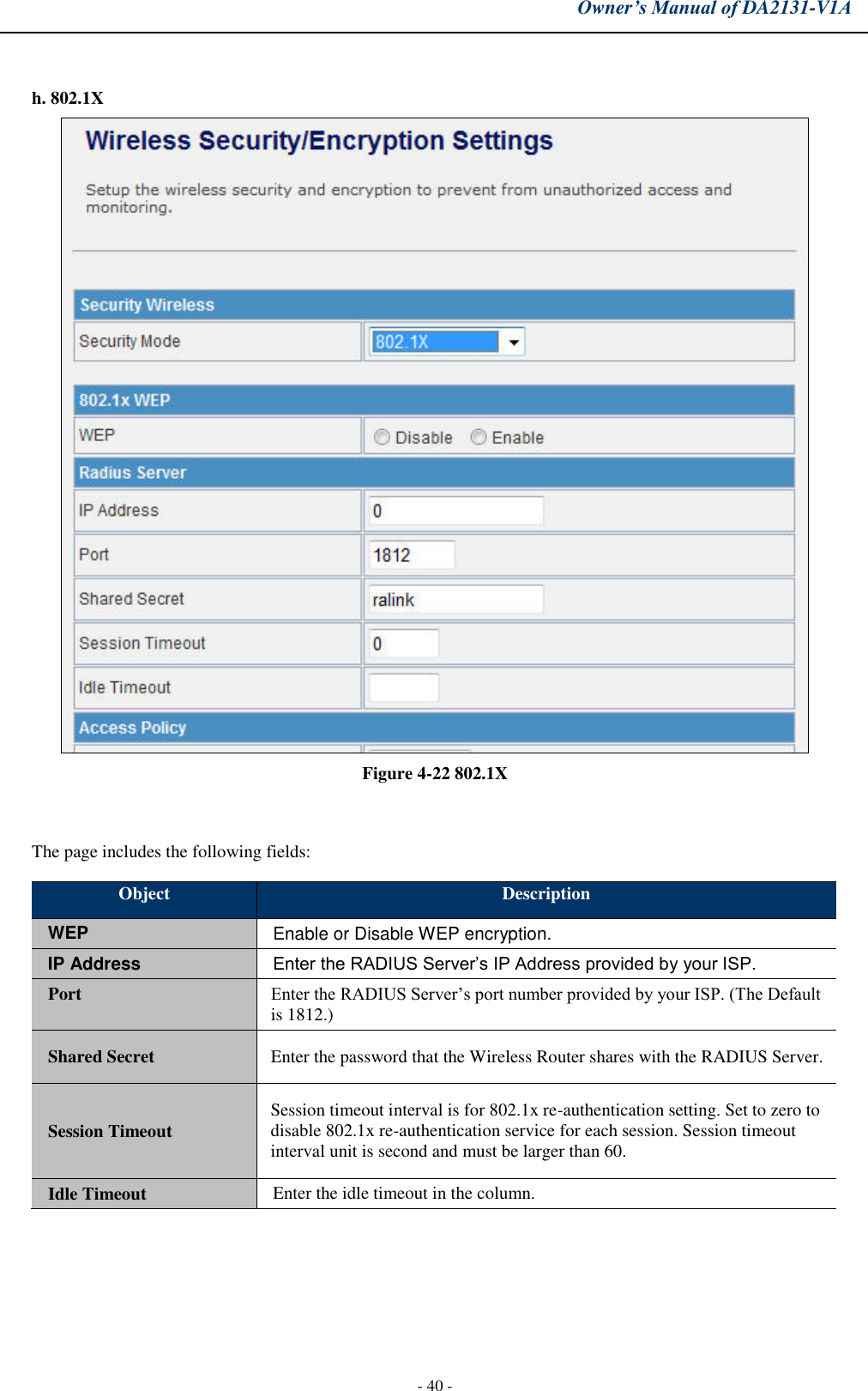
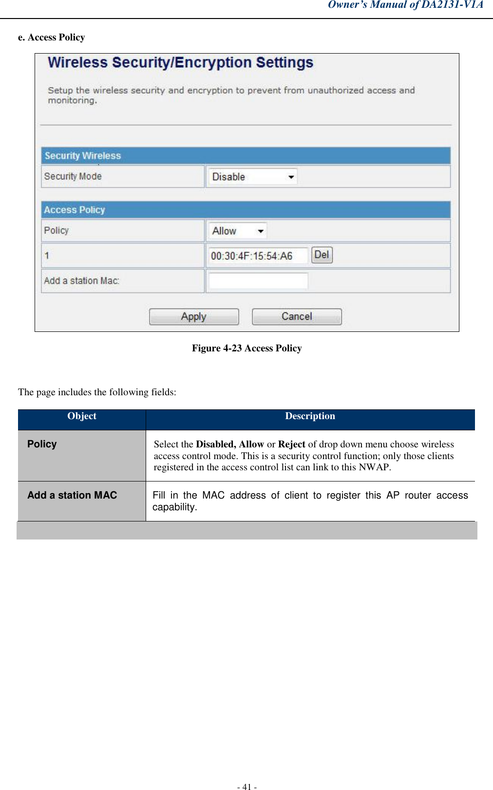
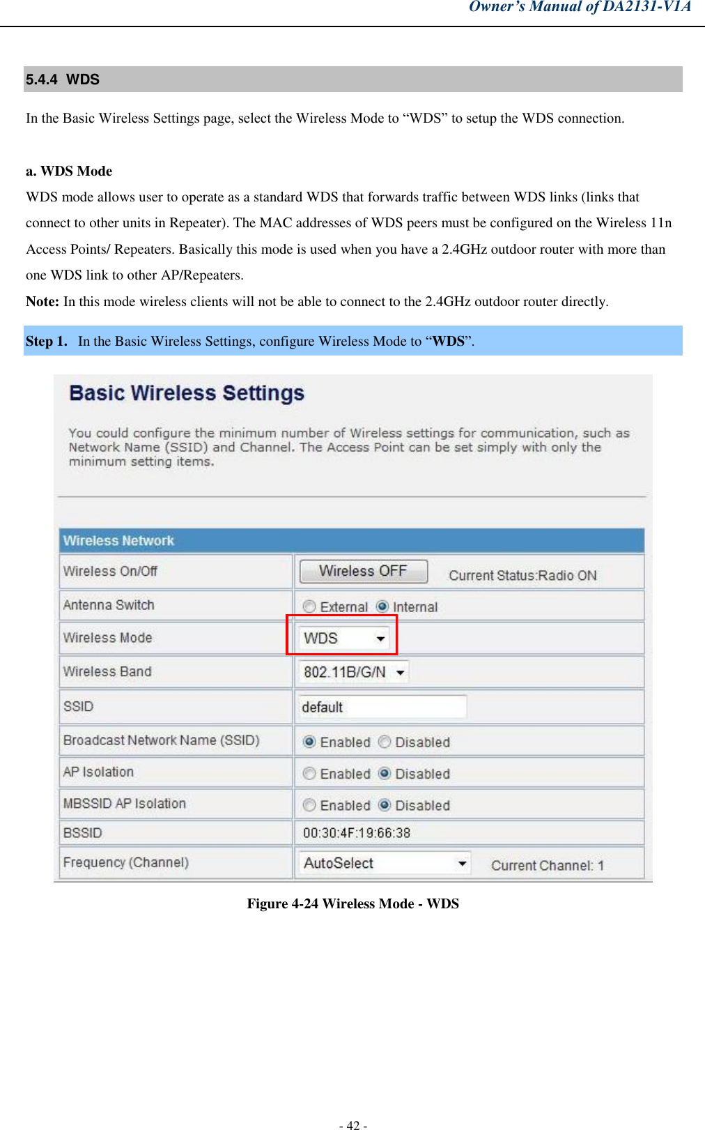
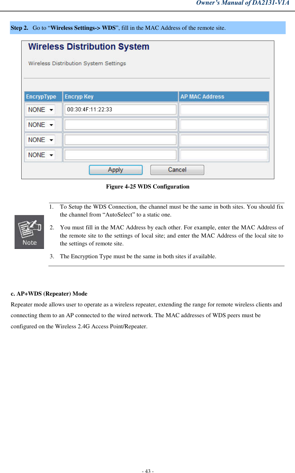
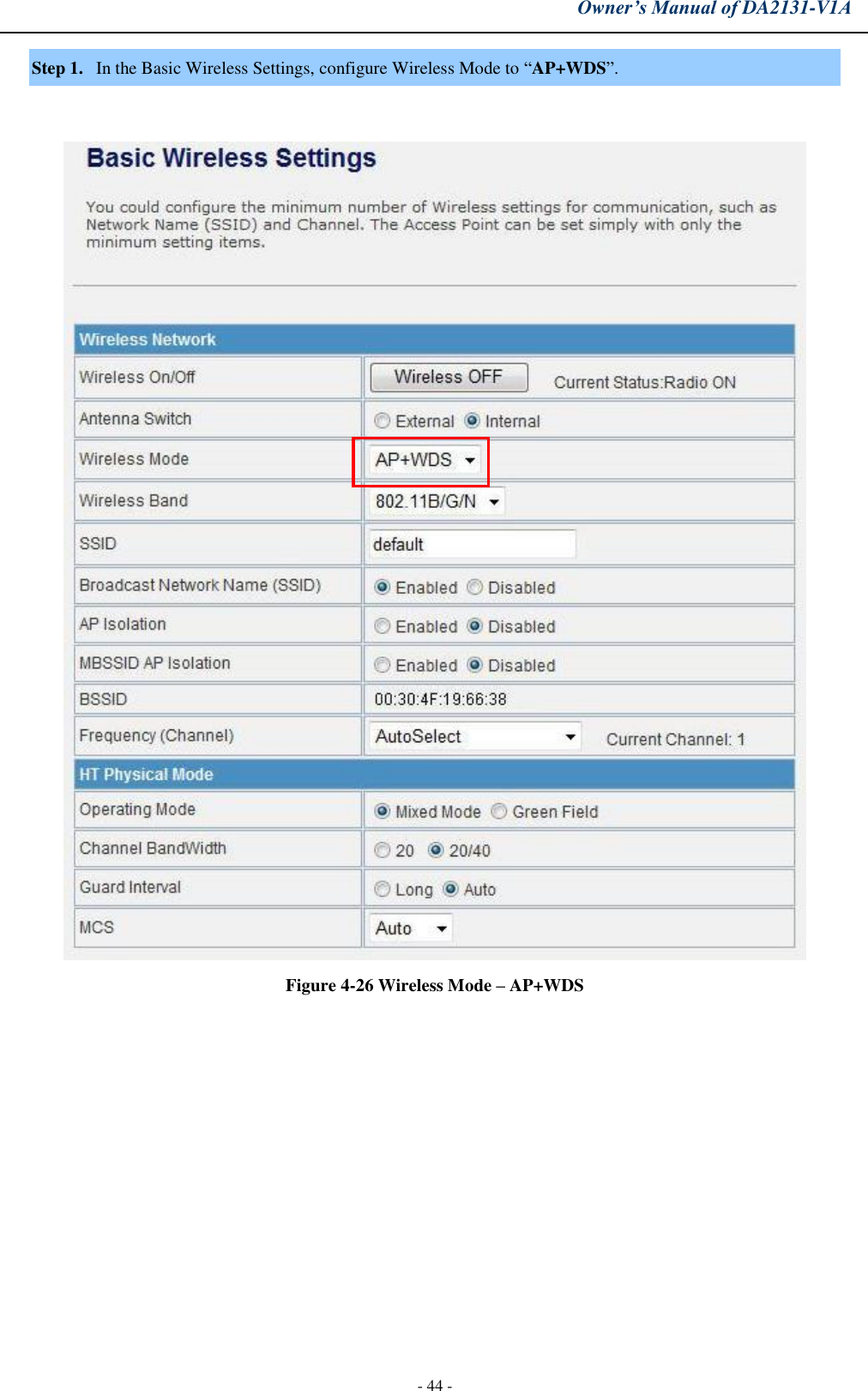
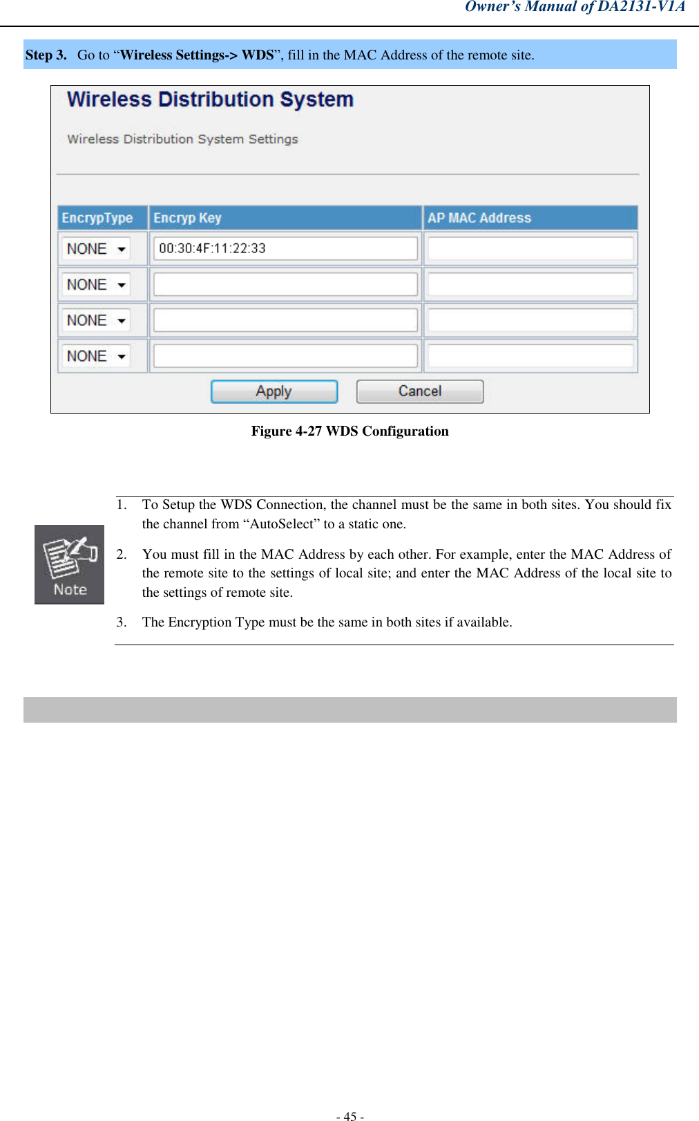
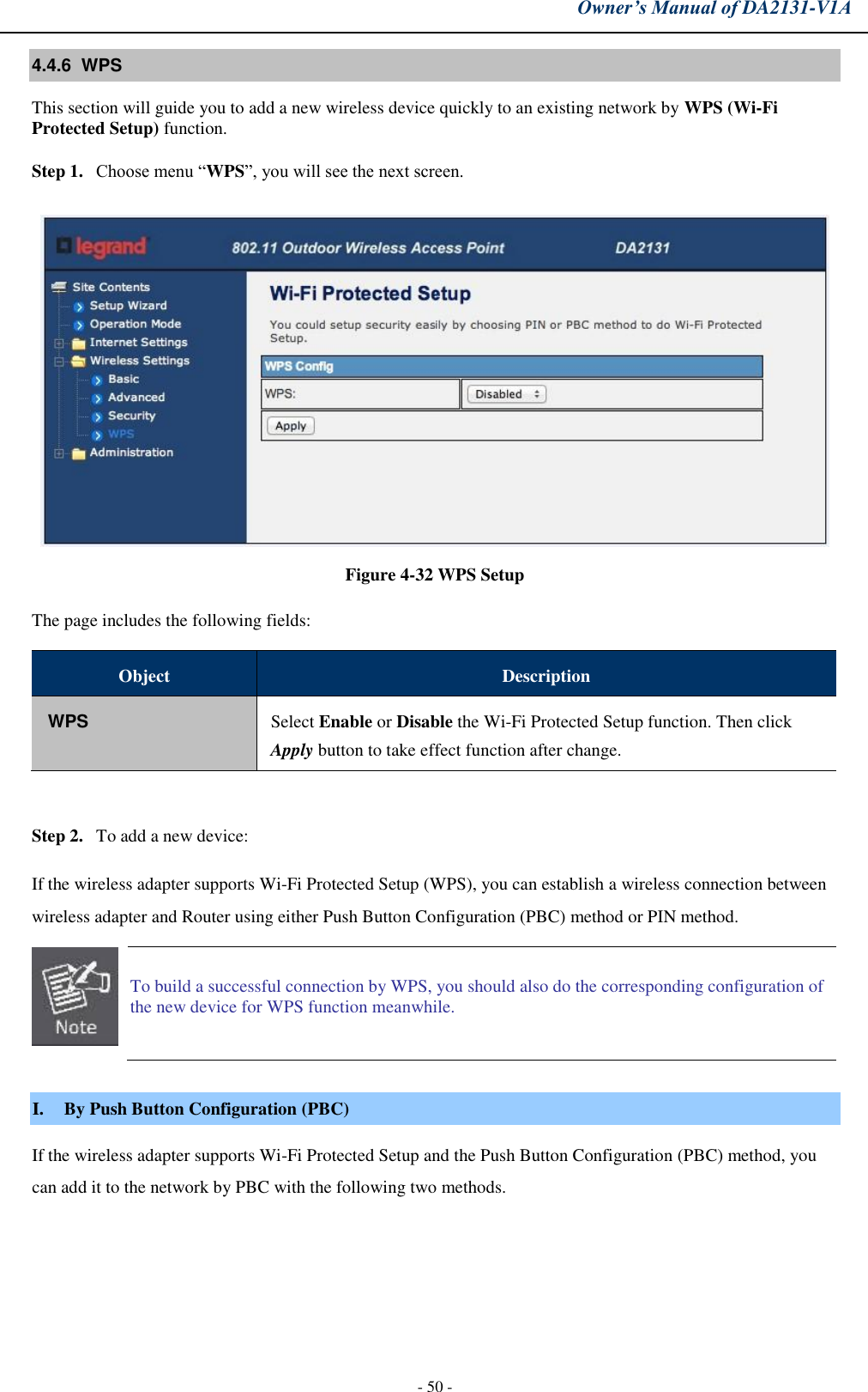
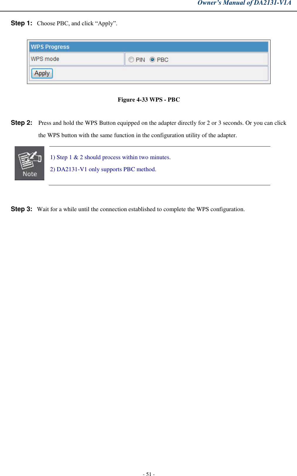
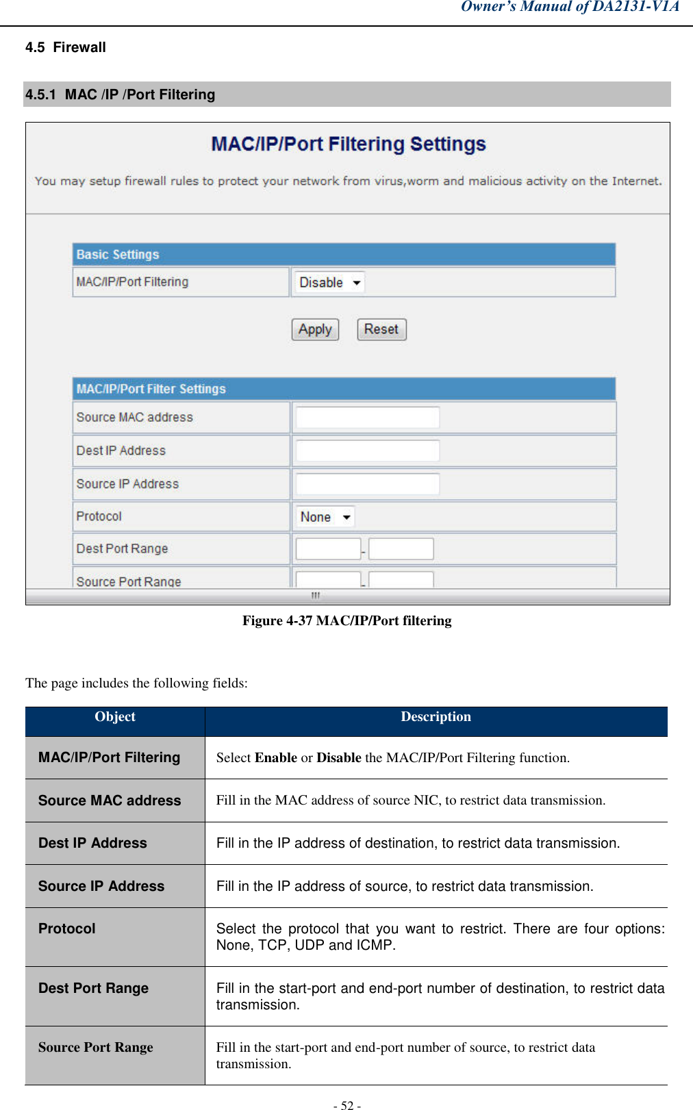
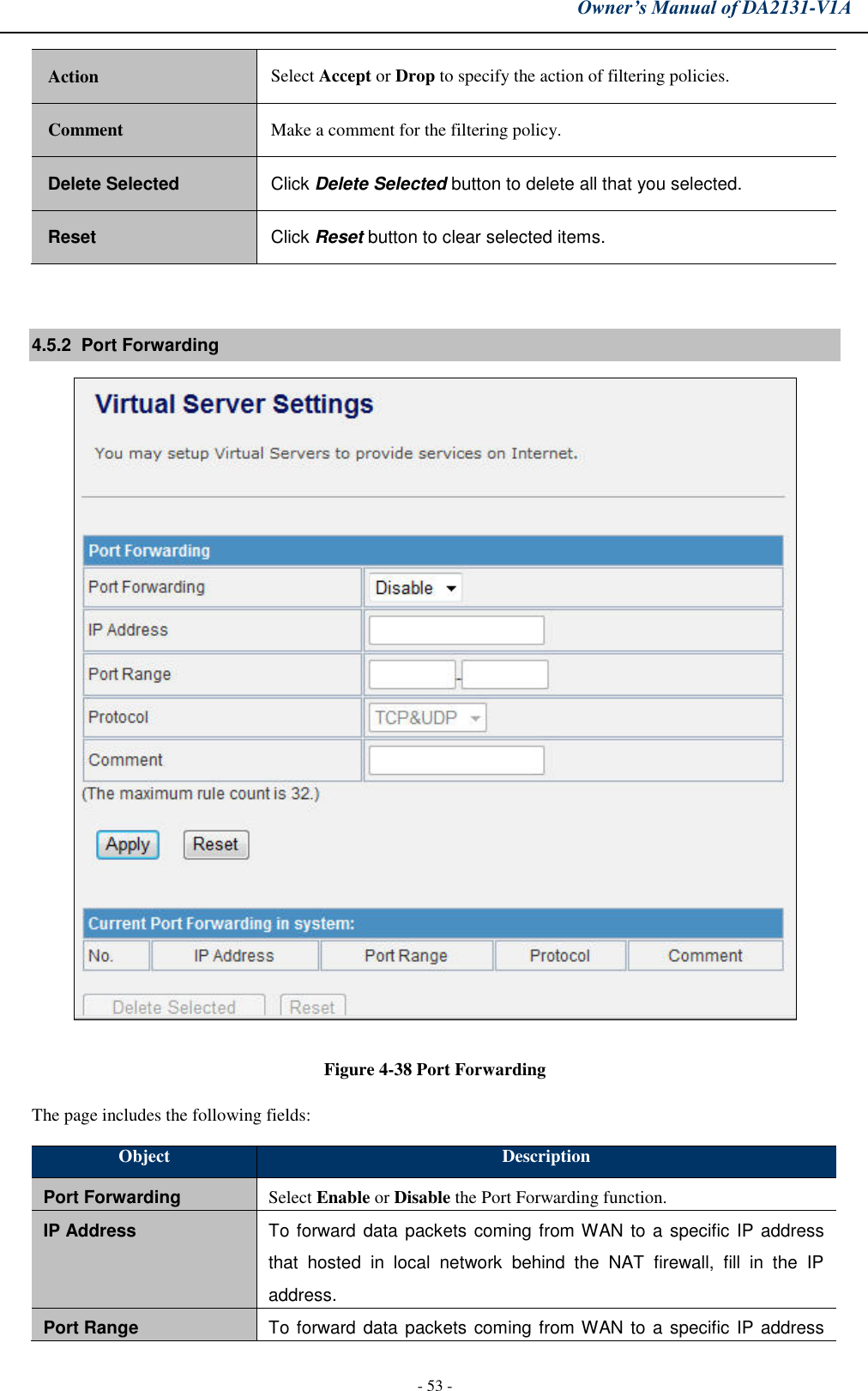
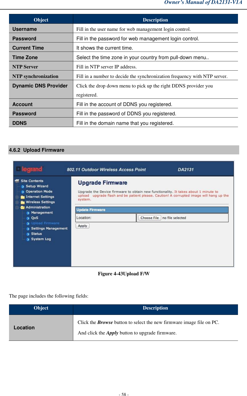
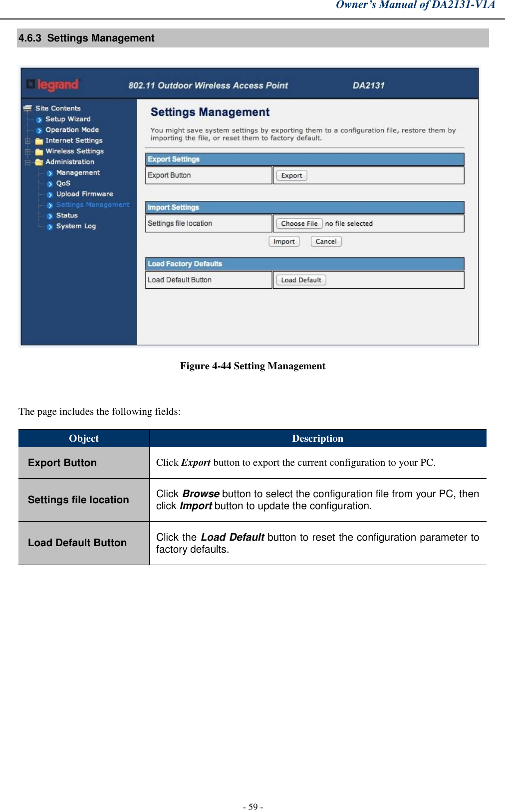
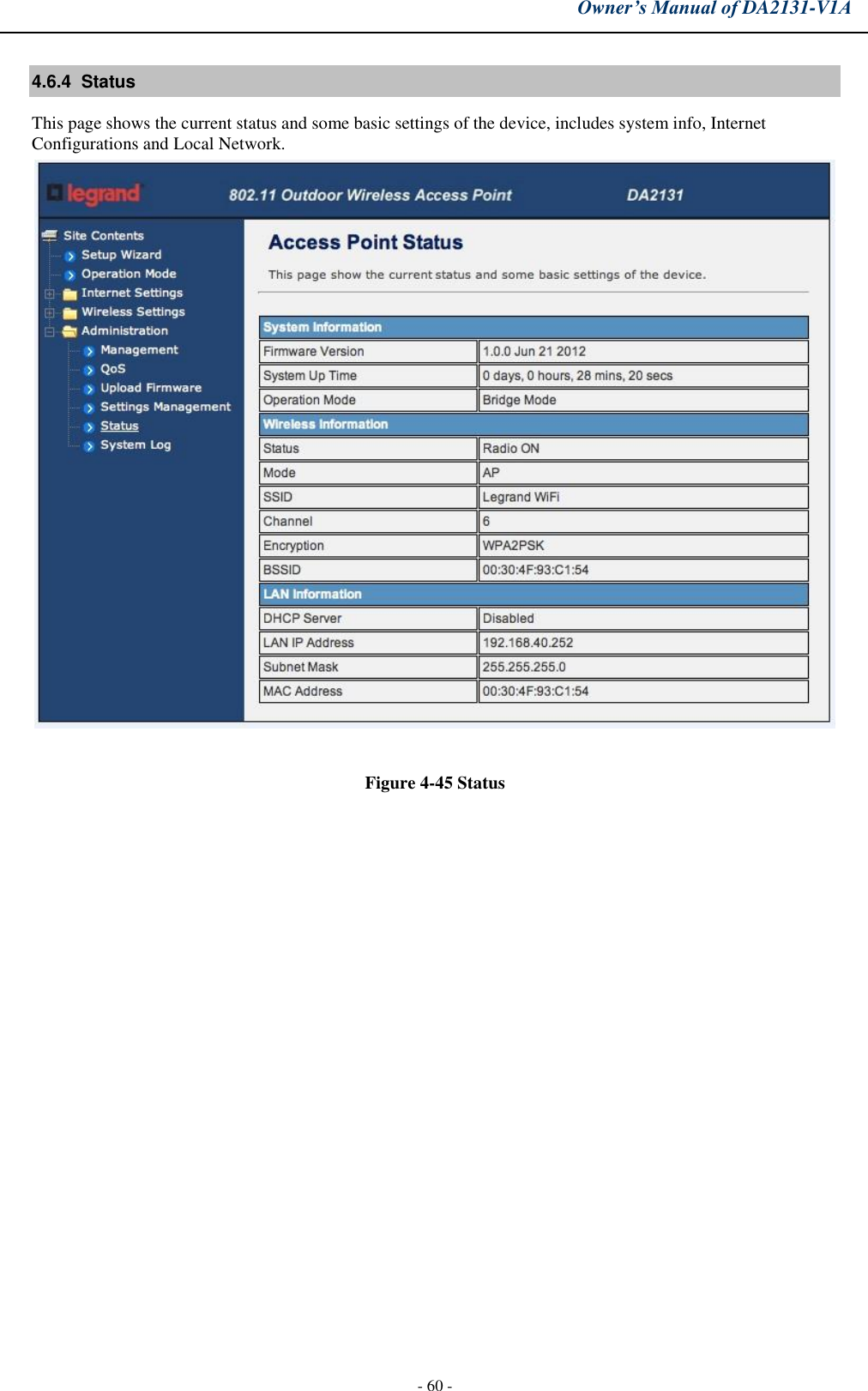
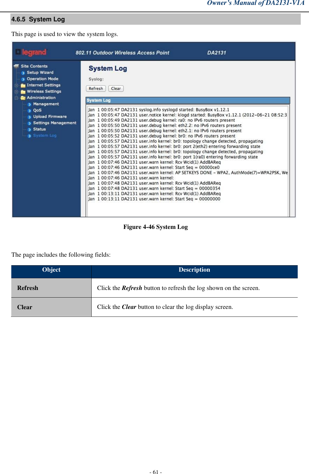
![FCC Radio Frequency Exposure Caution Statement In order to maintain compliance with the FCC RF exposure guidelines, this equipment should be installed and operated with minimum distance 20cm between the radiator and your body. Use only with supplied antenna. Unauthorized antenna, modification, or attachments could damage the transmitter and may violate FCC regulations. Any changes of modifications not expressly approved by the grantee of this device could void the users authority to operate the equipment. Installation and use of this Wireless LAN device must be in strict accordance with the instructions included in the user documentation provided with the product. Any changes or modifications (including the antennas) made to this device that are not expressly approved by the manufacturer may void the user’s authority to operate the equipment. The manufacturer is not responsible for any radio or television interference caused by unauthorized modification of this device, or the substitution or attachment of connecting cables and equipment other than manufacturer specified. It is the responsibility of the user to correct any interference caused by such unauthorized modification, substitution or attachment. Manufacturer and its authorized resellers or distributors will assume no liability for any damage or violation of government regulations arising from failing to comply with these guidelines. This device and its antenna(s) must not be co-located or operating in conjunction with any other antenna or transmitter. Declaration of Conformity (R&TTE directive 1999/5/EC) The following items were completed and are considered relevant and sufficient: • Essential requirements as in [Article 3]• Protection requirements for health and safety as in [Article 3.1a]• Testing for electric safety according to [EN 60950]• Protection requirements for electromagnetic compatibility in [Article 3.1b]• Testing for electromagnetic compatibility in [EN 301 489-1] & [EN 301]• Testing according to [489-17]• Effective use of the radio spectrum as in [Article 3.2]• Testing for radio test suites according to [EN 300 328-2]WARNING: TO PREVENT FIRE OR SHOCK HAZARD, DO NOT EXPOSE THIS PRODUCT TO RAIN OR MOISTURE. THE UNIT MUST NOT BE EXPOSED TO DRIPPING OR SPLASHING WATER. CAUTION: DO NOT OPEN THE UNIT. DO NOT PERFORM ANY SERVICING OTHER THAN THAT CONTAINED IN THE INSTALLATION AND TROUBLESHOOTING INSTRUCTIONS. REFER ALL SERVICING TO QUALIFIED SERVICE PERSONNEL. CAUTION: THIS DEVICE MUST BE INSTALLED AND USED IN STRICT ACCORDANCE WITH THE MANUFACTURER’S INSTRUCTIONS AS DESCRIBED IN THE USER DOCUMENTATION THAT COMES WITH THE PRODUCT. - iii -](https://usermanual.wiki/Pass-and-Seymour-d-b-a-Legrand/DA2131-V1A/User-Guide-2131230-Page-3.png)