Pathway Innovations and Technologies KR0319 Pilot User Manual
Pathway Innovations and Technologies, Inc. Pilot
UserManual.wiki
>
Pathway Innovations and Technologies
>
KR0319 User Manual
User Manual
Navigation menu
Upload a User Manual
Namespaces
Wiki Guide
HTML
PDF
Info
Views
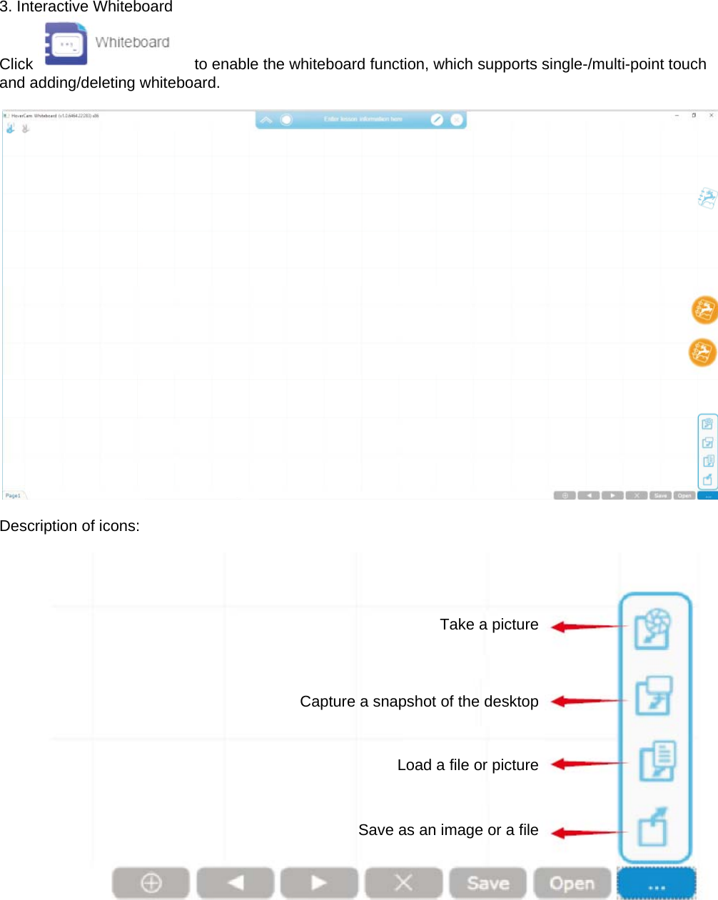
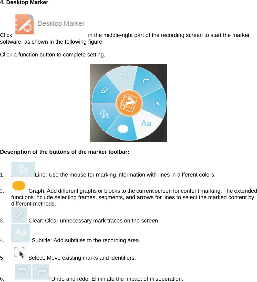
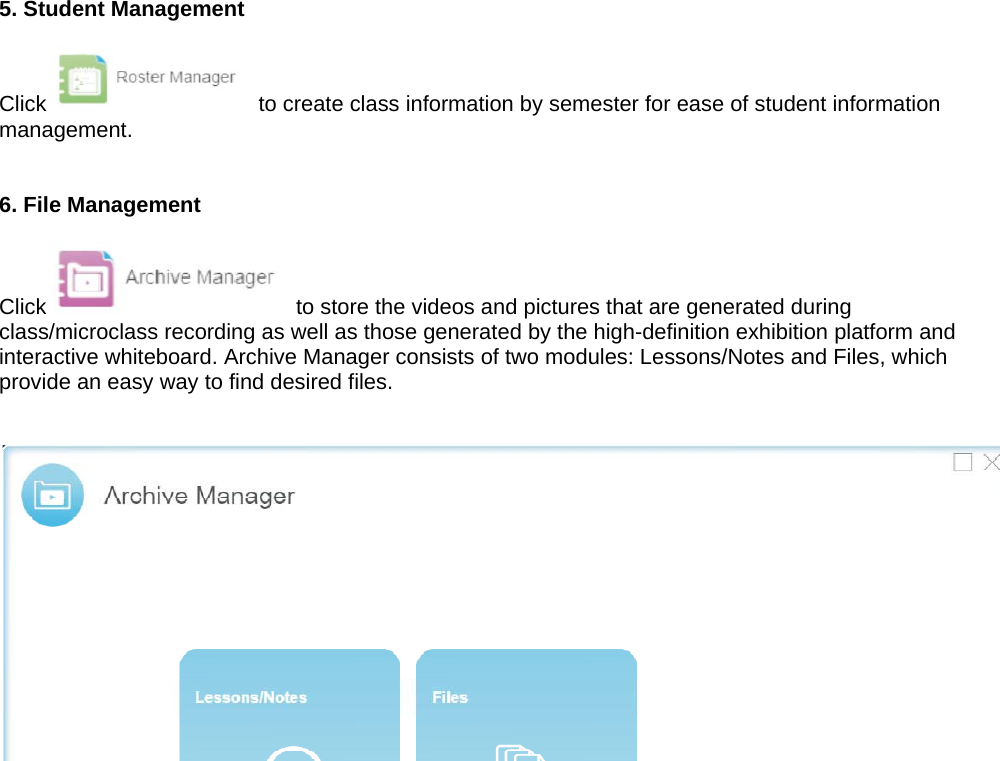
User Manual
Discussion / Help
Navigation