Patton Electronic 3088 Series Users Manual RocketLink G G.SHDSL NTU Getting Started Guide
3088 Series 3088
3088 Series to the manual 6d5d4835-c780-44bc-a7a4-263ca85521fc
2015-02-06
: Patton-Electronic Patton-Electronic-3088-Series-Users-Manual-517225 patton-electronic-3088-series-users-manual-517225 patton-electronic pdf
Open the PDF directly: View PDF ![]() .
.
Page Count: 82
- Summary Table of Contents
- Table of Contents
- List of Figures
- List of Tables
- About this guide
- Chapter 1 General information
- Chapter 2 Configuration
- Introduction
- Software (CLI) configuration
- Hardware (DIP-switch) configuration
- Configuring the DIP switches
- System reset mode
- DIP switch settings
- DIP switch settings for RocketLink-G models 3088/CA and 3088/D
- S1-1 through S1-7: Data Rate (RocketLink-G models 3088/CA and 3088/D)
- S1-8: TX Clock (RocketLink-G models 3088/CA and 3088/D)
- S2-2: Line Probe (Models 3088/CA and D)
- S2-3: Annex A/B (Models 3088/CA and D)
- S2-4 through S2-5: Clock Mode (Models 3088/CA and D)
- S2-6: DTE Loops (RocketLink-G models 3088/CA only)
- DIP switch settings for RocketLink-G models 3088/K and 3088/T
- S1-1 through S1-6: TimeSlots & Data Rate (RocketLink-G Models 3088/K and 3088/T)
- S1-7 and S1-8: Line Build Out (Models 3088/K and 3088/T)
- S2-2 Line Code (Models 3088/K and 3088/T)
- S2-3: Annex A/B (Models 3088/K and 3088/T)
- S2-4 through S2-5: Clock Mode (Models 3088/K and 3088/T))
- S2-6 through S2-8: Line Type (Models 3088/K and 3088/T)
- Console
- Remote Console
- RocketLink Plug ‘n’ Play
- Introduction
- Chapter 3 RocketLink-G installation
- Installation
- Connecting the twisted pair interface
- Connecting the Model 3088/CA (V.35) serial interface
- Connecting the Model 3088/D (X.21) serial interface
- Connecting the Model 3088/K serial interface
- Connect twisted pair (120 ohm) to E1 network
- Connecting dual coaxial cable (75 ohm) to E1 network
- Connecting the Model 3088/T (T1) serial interface
- Connecting power
- Installation
- Chapter 4 Operation
- Chapter 5 Remote console operation
- Chapter 6 Software Upgrade
- Chapter 7 Reset configuration to factory defaults
- Chapter 8 Contacting Patton for assistance
- Appendix A Compliance information
- Appendix B Specifications
- Appendix C Factory default values
- Appendix D Factory replacement parts and accessories
- Appendix E Interface pinouts
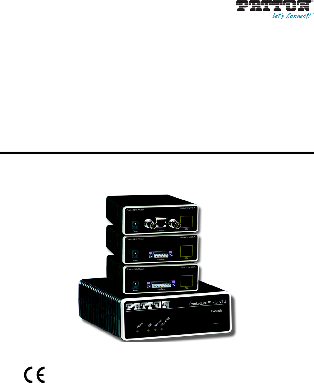
RocketLink-G Model 3088 Series
G.SHDSL NTU with fixed
serial interface
User Manual
Sales Office: +1 (301) 975-1000
Technical Support: +1 (301) 975-1007
E-mail: support@patton.com
WWW: www.patton.com
Part Number: 07M3088-GSG, Rev. J
Revised: February 15, 2012
Important
This is a Class A device and is not intended nor approved for use in a residential environment.
Start Installation
For Quick
Patton Electronics Company, Inc.
7622 Rickenbacker Drive
Gaithersburg, MD 20879 USA
Tel: +1 (301) 975-1000
Fax: +1 (301) 869-9293
Support: +1 (301) 975-1007
Web: www.patton.com
E-mail: support@patton.com
Trademark Statement
The term RocketLink-G is a trademark of Patton Electronics Company. All other
trademarks presented in this document are the property of their respective owners.
Copyright © 2012, Patton Electronics Company. All rights reserved.
The information in this document is subject to change without notice. Patton Elec-
tronics assumes no liability for errors that may appear in this document.
Warranty Information
Patton Electronics warrants all Model 3088 components to be free from defects, and
will—at our option—repair or replace the product should it fail within one year from
the first date of shipment.
This warranty is limited to defects in workmanship or materials, and does not cover
customer damage, abuse or unauthorized modification. If this product fails or does not
perform as warranted, your sole recourse shall be repair or replacement as described
above. Under no condition shall Patton Electronics be liable for any damages incurred
by the use of this product. These damages include, but are not limited to, the follow-
ing: lost profits, lost savings and incidental or consequential damages arising from the
use of or inability to use this product. Patton Electronics specifically disclaims all other
warranties, expressed or implied, and the installation or use of this product shall be
deemed an acceptance of these terms by the user.
Note
Conformity documents of all Patton products can be viewed online at
www.patton.com under the appropriate product page.

3
Summary Table of Contents
1General information...................................................................................................................................... 14
2Configuration................................................................................................................................................ 18
3RocketLink-G installation............................................................................................................................. 41
4Operation ...................................................................................................................................................... 51
5Remote console operation ............................................................................................................................. 55
6Software Upgrade .......................................................................................................................................... 60
7Reset configuration to factory defaults.......................................................................................................... 62
8Contacting Patton for assistance ................................................................................................................... 64
ACompliance information .............................................................................................................................. 67
BSpecifications ................................................................................................................................................ 71
CFactory default values ................................................................................................................................... 75
DFactory replacement parts and accessories .................................................................................................... 78
EInterface pinouts .......................................................................................................................................... 80

4
Table of Contents
Summary Table of Contents ........................................................................................................................... 3
Table of Contents ........................................................................................................................................... 4
List of Figures ................................................................................................................................................. 8
List of Tables .................................................................................................................................................. 9
About this guide ........................................................................................................................................... 10
Audience............................................................................................................................................................... 10
Structure............................................................................................................................................................... 10
Precautions ........................................................................................................................................................... 11
Safety when working with electricity ...............................................................................................................12
.......................................................................................................................................................................13
General observations .......................................................................................................................................13
Typographical conventions used in this document................................................................................................ 13
General conventions .......................................................................................................................................13
1General information...................................................................................................................................... 14
RocketLink-G 3088 overview................................................................................................................................15
Serial interface types ..............................................................................................................................................15
Features.................................................................................................................................................................15
Power input connector ..........................................................................................................................................16
External AC universal power supply ................................................................................................................16
External 48 VDC power supply ......................................................................................................................17
2Configuration................................................................................................................................................ 18
Introduction..........................................................................................................................................................19
Software (CLI) configuration ..........................................................................................................................19
Hardware (DIP-switch) configuration .............................................................................................................19
Configuring the DIP switches .........................................................................................................................22
System reset mode ...........................................................................................................................................23
Software upgrades .....................................................................................................................................23
Configuration reset to factory defaults .......................................................................................................23
DIP switch settings .........................................................................................................................................23
DIP switch settings for RocketLink-G models 3088/CA and 3088/D .............................................................24
S1-1 through S1-7: Data Rate (RocketLink-G models 3088/CA and 3088/D) .........................................25
S1-8: TX Clock (RocketLink-G models 3088/CA and 3088/D) ...............................................................27
S2-2: Line Probe (Models 3088/CA and D) ..............................................................................................27
S2-3: Annex A/B (Models 3088/CA and D) ..............................................................................................27
S2-4 through S2-5: Clock Mode (Models 3088/CA and D) ......................................................................27
X.21 operation. ...................................................................................................................................28
S2-6: DTE Loops (RocketLink-G models 3088/CA only) ........................................................................28
DIP switch settings for RocketLink-G models 3088/K and 3088/T ................................................................29
S1-1 through S1-6: TimeSlots & Data Rate (RocketLink-G Models 3088/K and 3088/T) .......................30
S1-7 and S1-8: Line Build Out (Models 3088/K and 3088/T) ..................................................................31

5
Model 3088 Series User Manual Table of Contents
S2-2 Line Code (Models 3088/K and 3088/T) .........................................................................................31
S2-3: Annex A/B (Models 3088/K and 3088/T) .......................................................................................31
S2-4 through S2-5: Clock Mode (Models 3088/K and 3088/T)) ..............................................................31
S2-6 through S2-8: Line Type (Models 3088/K and 3088/T) ...................................................................32
Console ...........................................................................................................................................................32
Help Commands .......................................................................................................................................35
System Configuration Commands ............................................................................................................36
System Status Commands .........................................................................................................................36
DSL Configuration Commands ................................................................................................................36
DSL Status Command ..............................................................................................................................37
DSL Clear Errcntrs Command ..................................................................................................................37
T1/E1 Configuration Commands .............................................................................................................37
T1/E1 Status Commands ..........................................................................................................................38
Remote Console ..............................................................................................................................................38
Example Command Line Interface Session ................................................................................................38
RocketLink Plug ‘n’ Play .................................................................................................................................39
3RocketLink-G installation............................................................................................................................. 41
Installation ............................................................................................................................................................42
Connecting the twisted pair interface ..............................................................................................................42
Connecting the Model 3088/CA (V.35) serial interface ..................................................................................43
Connecting the Model 3088/CA (V.35) to a “DTE” device ......................................................................43
Connecting the Model 3088/CA (V.35) to a “DCE” device ......................................................................43
Connecting the Model 3088/D (X.21) serial interface ....................................................................................44
Connecting the Model 3088/D (X.21) to a “DCE” or “DTE” device .......................................................44
Opening the Case ......................................................................................................................................45
Connecting the Model 3088/K serial interface ................................................................................................46
Connecting the Model 3088/K to an E1 Network ....................................................................................46
Connect twisted pair (120 ohm) to E1 network ..............................................................................................47
Connecting dual coaxial cable (75 ohm) to E1 network ..................................................................................47
Connecting the Model 3088/T (T1) serial interface ........................................................................................48
Connect Twisted Pair (100 ohm) to T1 Network .....................................................................................48
Connecting power ...........................................................................................................................................49
External AC universal power supply ..........................................................................................................49
DC Power .................................................................................................................................................50
4Operation ...................................................................................................................................................... 51
Introduction..........................................................................................................................................................52
Power-up ........................................................................................................................................................52
LED status monitors .......................................................................................................................................52
Power (Green) ...........................................................................................................................................52
DSL (Green) .............................................................................................................................................52
Link (Green) (Models K and T only) ........................................................................................................52
Term (Green) [Models C and D] ..............................................................................................................53
TM/ER (Red) ...........................................................................................................................................53

6
Model 3088 Series User Manual Table of Contents
LOS (Red) [Models K and T] ...................................................................................................................53
Test modes ......................................................................................................................................................53
Loopbacks .................................................................................................................................................54
Patterns .....................................................................................................................................................54
5Remote console operation ............................................................................................................................. 55
Introduction..........................................................................................................................................................56
Establishing a Remote Console Session ...........................................................................................................56
How to Connect .......................................................................................................................................56
How to Disconnect ...................................................................................................................................57
Differences in Local and Remote Control Session Behavior ......................................................................58
6Software Upgrade .......................................................................................................................................... 60
Introduction..........................................................................................................................................................61
7Reset configuration to factory defaults.......................................................................................................... 62
Introduction..........................................................................................................................................................63
8Contacting Patton for assistance ................................................................................................................... 64
Introduction..........................................................................................................................................................65
Contact information..............................................................................................................................................65
Patton support headquarters in the USA .........................................................................................................65
Alternate Patton support for Europe, Middle East, and Africa (EMEA) ..........................................................65
Warranty Service and Returned Merchandise Authorizations (RMAs)...................................................................65
Warranty coverage ..........................................................................................................................................65
Out-of-warranty service .............................................................................................................................66
Returns for credit ......................................................................................................................................66
Return for credit policy .............................................................................................................................66
RMA numbers ................................................................................................................................................66
Shipping instructions ................................................................................................................................66
ACompliance information .............................................................................................................................. 67
Compliance ...........................................................................................................................................................68
EMC ...............................................................................................................................................................68
Safety ..............................................................................................................................................................68
PSTN Regulatory ............................................................................................................................................68
FCC Part 68 (ACTA) Statement ...........................................................................................................................68
Radio and TV Interference (FCC Part 15) ............................................................................................................69
Industry Canada Notice ........................................................................................................................................69
CE Declaration of Conformity..............................................................................................................................69
Authorized European Representative .....................................................................................................................70
BSpecifications ................................................................................................................................................ 71
Clocking modes.....................................................................................................................................................72
DTE rate...............................................................................................................................................................72
Serial interface .......................................................................................................................................................72
Serial connector.....................................................................................................................................................72
Diagnostics............................................................................................................................................................72

7
Model 3088 Series User Manual Table of Contents
Status LEDs...........................................................................................................................................................72
Power (Green) ...........................................................................................................................................72
DSL (Green) .............................................................................................................................................72
Link (Green) (T1/E1 only) .......................................................................................................................72
Term (Green) ............................................................................................................................................73
TM/ER (Red) ...........................................................................................................................................73
Configuration........................................................................................................................................................73
Power and power supply specifications ..................................................................................................................73
External AC universal power supply ................................................................................................................73
External 48 VDC power supply ......................................................................................................................74
Transmission line ..................................................................................................................................................74
Line coding ...........................................................................................................................................................74
Line rates (DSL line) .............................................................................................................................................74
Line interface.........................................................................................................................................................74
G.SHDSL physical connection..............................................................................................................................74
Environment .........................................................................................................................................................74
CFactory default values ................................................................................................................................... 75
Factory default values for software-configurable parameters...................................................................................76
DFactory replacement parts and accessories .................................................................................................... 78
Factory replacement parts and accessories..............................................................................................................79
EInterface pinouts .......................................................................................................................................... 80
RJ-11 non-shielded DSL port................................................................................................................................81
V.35 interface........................................................................................................................................................81
T1/E1 interface .....................................................................................................................................................81
X.21 interface ........................................................................................................................................................82
RS-232 console interface pin assignments..............................................................................................................82

8
List of Figures
1 RocketLink-G 3088 . . . . . . . . . . . . . . . . . . . . . . . . . . . . . . . . . . . . . . . . . . . . . . . . . . . . . . . . . . . . . . . . . . . . . 15
2 Power connection barrel receptacle 5 VDC diagram . . . . . . . . . . . . . . . . . . . . . . . . . . . . . . . . . . . . . . . . . . . . . 16
3 RocketLink-G (Model 3088/D shown) . . . . . . . . . . . . . . . . . . . . . . . . . . . . . . . . . . . . . . . . . . . . . . . . . . . . . . 19
4 Underside of Model 3088 showing location of DIP switches . . . . . . . . . . . . . . . . . . . . . . . . . . . . . . . . . . . . . . 22
5 Close-up of configuration switches (all sets are identical appearance) . . . . . . . . . . . . . . . . . . . . . . . . . . . . . . . . 23
6 Typical RocketLink Plug ‘n’ Play Application . . . . . . . . . . . . . . . . . . . . . . . . . . . . . . . . . . . . . . . . . . . . . . . . . . 40
7 Model 3088 V.35/X.21 interfaces . . . . . . . . . . . . . . . . . . . . . . . . . . . . . . . . . . . . . . . . . . . . . . . . . . . . . . . . . . . 42
8 Connecting the Model 3088/CA to V.35 Serial DTE . . . . . . . . . . . . . . . . . . . . . . . . . . . . . . . . . . . . . . . . . . . . 43
9 Connecting the Model 3088/CA to V.35 Serial DCE . . . . . . . . . . . . . . . . . . . . . . . . . . . . . . . . . . . . . . . . . . . . 44
10 Connecting the Model 3088/D to X.21 DTE or DCE . . . . . . . . . . . . . . . . . . . . . . . . . . . . . . . . . . . . . . . . . . . 45
11 Opening the 3088 case with a small screwdriver . . . . . . . . . . . . . . . . . . . . . . . . . . . . . . . . . . . . . . . . . . . . . . . . 45
12 Setting the DCE/DTE Strap (X.21 only) . . . . . . . . . . . . . . . . . . . . . . . . . . . . . . . . . . . . . . . . . . . . . . . . . . . . . 46
13 120 Ohm RJ-48C E1 interface . . . . . . . . . . . . . . . . . . . . . . . . . . . . . . . . . . . . . . . . . . . . . . . . . . . . . . . . . . . . . 47
14 RJ-45 cable diagram for E1 connection . . . . . . . . . . . . . . . . . . . . . . . . . . . . . . . . . . . . . . . . . . . . . . . . . . . . . . 47
15 Model 3088/K rear panel . . . . . . . . . . . . . . . . . . . . . . . . . . . . . . . . . . . . . . . . . . . . . . . . . . . . . . . . . . . . . . . . . 48
16 120 Ohm RJ-48C T1 interface . . . . . . . . . . . . . . . . . . . . . . . . . . . . . . . . . . . . . . . . . . . . . . . . . . . . . . . . . . . . . 48
17 RJ-45 cable diagram for T1 connection . . . . . . . . . . . . . . . . . . . . . . . . . . . . . . . . . . . . . . . . . . . . . . . . . . . . . . 49
18 DC Power Supply . . . . . . . . . . . . . . . . . . . . . . . . . . . . . . . . . . . . . . . . . . . . . . . . . . . . . . . . . . . . . . . . . . . . . . . 50
19 Model 3088/CA front panel . . . . . . . . . . . . . . . . . . . . . . . . . . . . . . . . . . . . . . . . . . . . . . . . . . . . . . . . . . . . . . . 52
20 3088/S Model Front Panel . . . . . . . . . . . . . . . . . . . . . . . . . . . . . . . . . . . . . . . . . . . . . . . . . . . . . . . . . . . . . . . . 53
21 Model 3088 Block Diagram . . . . . . . . . . . . . . . . . . . . . . . . . . . . . . . . . . . . . . . . . . . . . . . . . . . . . . . . . . . . . . . 53
22 Local Analog Loopback diagram . . . . . . . . . . . . . . . . . . . . . . . . . . . . . . . . . . . . . . . . . . . . . . . . . . . . . . . . . . . . 54
23 Remote Digital Loopback diagram . . . . . . . . . . . . . . . . . . . . . . . . . . . . . . . . . . . . . . . . . . . . . . . . . . . . . . . . . . 54
24 Remote control session diagram . . . . . . . . . . . . . . . . . . . . . . . . . . . . . . . . . . . . . . . . . . . . . . . . . . . . . . . . . . . . 56
25 Opening a typical remote console session . . . . . . . . . . . . . . . . . . . . . . . . . . . . . . . . . . . . . . . . . . . . . . . . . . . . . 57
26 Remote control session with LAL diagram . . . . . . . . . . . . . . . . . . . . . . . . . . . . . . . . . . . . . . . . . . . . . . . . . . . . 58
27 Power connection barrel receptacle 5 VDC diagram . . . . . . . . . . . . . . . . . . . . . . . . . . . . . . . . . . . . . . . . . . . . . 73

9
List of Tables
1 General conventions . . . . . . . . . . . . . . . . . . . . . . . . . . . . . . . . . . . . . . . . . . . . . . . . . . . . . . . . . . . . . . . . . . . . . 13
2 RocketLink-G configurable parameters . . . . . . . . . . . . . . . . . . . . . . . . . . . . . . . . . . . . . . . . . . . . . . . . . . . . . . . 20
3 Model 3088/CA and 3088/D - S1 DIP-Switch Functions . . . . . . . . . . . . . . . . . . . . . . . . . . . . . . . . . . . . . . . . 24
4 Model 3088/CA and 3088/D - S2 DIP-Switch Functions . . . . . . . . . . . . . . . . . . . . . . . . . . . . . . . . . . . . . . . . 24
5 S1-1 through S1-7 Data Rate DIP switch settings . . . . . . . . . . . . . . . . . . . . . . . . . . . . . . . . . . . . . . . . . . . . . . . 25
6 S1-8 TX Clock DIP switch settings . . . . . . . . . . . . . . . . . . . . . . . . . . . . . . . . . . . . . . . . . . . . . . . . . . . . . . . . . 27
7 S2-2 Line Probe Switch Settings . . . . . . . . . . . . . . . . . . . . . . . . . . . . . . . . . . . . . . . . . . . . . . . . . . . . . . . . . . . . 27
8 S2-3 Annex Type settings . . . . . . . . . . . . . . . . . . . . . . . . . . . . . . . . . . . . . . . . . . . . . . . . . . . . . . . . . . . . . . . . . 27
9 S2-4 and S2-5 Clock Mode Settings . . . . . . . . . . . . . . . . . . . . . . . . . . . . . . . . . . . . . . . . . . . . . . . . . . . . . . . . . 27
10 X.21 Clocking . . . . . . . . . . . . . . . . . . . . . . . . . . . . . . . . . . . . . . . . . . . . . . . . . . . . . . . . . . . . . . . . . . . . . . . . . 28
11 S2-6 V.35 Loopback settings . . . . . . . . . . . . . . . . . . . . . . . . . . . . . . . . . . . . . . . . . . . . . . . . . . . . . . . . . . . . . . 28
12 Model 3088/K and 3088/T S1 DIP-Switch Functions . . . . . . . . . . . . . . . . . . . . . . . . . . . . . . . . . . . . . . . . . . . 29
13 Model 3088/K and 3088/T S2 DIP-Switch Functions . . . . . . . . . . . . . . . . . . . . . . . . . . . . . . . . . . . . . . . . . . . 29
14 S1-1 through S1-6 Timeslots & DSL Data Rate DIP switch settings . . . . . . . . . . . . . . . . . . . . . . . . . . . . . . . . 30
15 S1-7 – S1-8: Line Build Out Settings . . . . . . . . . . . . . . . . . . . . . . . . . . . . . . . . . . . . . . . . . . . . . . . . . . . . . . . . 31
16 S2-2 Line Code Switch Settings . . . . . . . . . . . . . . . . . . . . . . . . . . . . . . . . . . . . . . . . . . . . . . . . . . . . . . . . . . . . 31
17 S2-3 Annex Type settings . . . . . . . . . . . . . . . . . . . . . . . . . . . . . . . . . . . . . . . . . . . . . . . . . . . . . . . . . . . . . . . . . 31
18 S2-4 and S2-5 Clock Mode Settings . . . . . . . . . . . . . . . . . . . . . . . . . . . . . . . . . . . . . . . . . . . . . . . . . . . . . . . . . 31
19 S2-6 through S2-8 Line Type Settings . . . . . . . . . . . . . . . . . . . . . . . . . . . . . . . . . . . . . . . . . . . . . . . . . . . . . . . 32
20 3088/CA and 3088/D . . . . . . . . . . . . . . . . . . . . . . . . . . . . . . . . . . . . . . . . . . . . . . . . . . . . . . . . . . . . . . . . . . . 76
21 3088/K . . . . . . . . . . . . . . . . . . . . . . . . . . . . . . . . . . . . . . . . . . . . . . . . . . . . . . . . . . . . . . . . . . . . . . . . . . . . . . . 76
22 3088/T . . . . . . . . . . . . . . . . . . . . . . . . . . . . . . . . . . . . . . . . . . . . . . . . . . . . . . . . . . . . . . . . . . . . . . . . . . . . . . . 77

10
About this guide
This guide describes installing and operating the Patton Electronics Model 3088 G.SHDSL
RocketLink-G™ NTU.
Audience
This guide is intended for the following users:
•Operators
•Installers
•Maintenance technicians
Structure
This guide contains the following chapters and appendices:
•Chapter 1 on page 14 provides information about NTU features and capabilities
•Chapter 2 on page 18 contains an overview describing NTU operation and applications
•Chapter 3 on page 41 provides hardware installation procedures
•Chapter 4 on page 51 provides quick-start procedures for configuring the RocketLink-G NTU
•Chapter 5 on page 55 describes how to install and operate the RocketLink-G NTU
•Chapter 6 on page 60 describes how to configure the RocketLink-G NTU, save the configuration, reset the
NTU to the factory default condition, and upgrade the system software
•Chapter 7 on page 62 describes the system tools that can be used to diagnose problems with the NTU
•Chapter 8 on page 64 contains information on contacting Patton technical support for assistance
•Appendix A on page 67 contains compliance information for the RocketLink-G NTU
•Appendix B on page 71 contains specifications for the NTU
•Appendix D on page 78 provides cable recommendations
•Appendix E on page 80 describes the NTU’s ports and pin-outs
For best results, read the contents of this guide before you install the NTU.
11
Model 3088 Series User Manual
Precautions
Notes, cautions, and warnings, which have the following meanings, are used throughout this guide to help you
become aware of potential problems. Warnings are intended to prevent safety hazards that could result in per-
sonal injury. Cautions are intended to prevent situations that could result in property damage or
impaired functioning.
Note
A note presents additional information or interesting sidelights.
The shock hazard symbol and WARNING heading indicate a potential electric
shock hazard. Strictly follow the warning instructions to avoid injury caused
by electric shock.
The alert symbol and WARNING heading indicate a potential safety hazard.
Strictly follow the warning instructions to avoid personal injury.
The shock hazard symbol and CAUTION heading indicate a
potential electric shock hazard. Strictly follow the instructions to
avoid property damage caused by electric shock.
The alert symbol and CAUTION heading indicate a potential haz-
ard. Strictly follow the instructions to avoid property damage.
WARNING
WARNING
CAUTION
CAUTION

12
Model 3088 Series User Manual
Safety when working with electricity
•
Do not open the device when the power cord is connected. For systems
without a power switch and without an external power adapter, line volt-
ages are present within the device when the power cord is connected.
•
For devices with an external power adapter, the power adapter shall be a
listed imited Power Source The mains outlet that is utilized to power the
device shall be within 10 feet (3 meters) of the device, shall be easily
accessible, and protected by a circuit breaker in compliance with local reg-
ulatory requirements.
•
For AC powered devices, ensure that the power cable used meets all appli-
cable standards for the country in which it is to be installed.
•
For AC powered devices which have 3 conductor power plugs (L1, L2 &
GND or Hot, Neutral & Safety/Protective Ground), the wall outlet (or
socket) must have an earth ground.
•
For DC powered devices, ensure that the interconnecting cables are rated
for proper voltage, current, anticipated temperature, flammability, and
mechanical serviceability.
•
WAN, LAN & PSTN ports (connections) may have hazardous voltages
present regardless of whether the device is powered ON or OFF. PSTN
relates to interfaces such as telephone lines, FXS, FXO, DSL, xDSL, T1, E1,
ISDN, Voice, etc. These are known as “hazardous network voltages” and
to avoid electric shock use caution when working near these ports. When
disconnecting cables for these ports, detach the far end connection first.
•
Do not work on the device or connect or disconnect cables during periods
of lightning activity.
This device contains no user serviceable parts. This device can only be
repaired by qualified service personnel.
This device is NOT intended nor approved for connection to the PSTN. It is
intended only for connection to customer premise equipment.
In accordance with the requirements of council directive 2002/
96/EC on Waste of Electrical and Electronic Equipment (WEEE),
ensure that at end-of-life you separate this product from other
waste and scrap and deliver to the WEEE collection system in
your country for recycling.
WARNING
WARNING
WARNING
13
Model 3088 Series User Manual
General observations
•Clean the case with a soft slightly moist anti-static cloth
•Place the unit on a flat surface and ensure free air circulation
•Avoid exposing the unit to direct sunlight and other heat sources
•Protect the unit from moisture, vapors, and corrosive liquids
Typographical conventions used in this document
This section describes the typographical conventions and terms used in this guide.
General conventions
The procedures described in this manual use the following text conventions:
Electrostatic Discharge (ESD) can damage equipment and impair
electrical circuitry. It occurs when electronic printed circuit cards
are improperly handled and can result in complete or intermittent
failures. Do the following to prevent ESD:
•
Always follow ESD prevention procedures when removing and
replacing cards.
•
Wear an ESD-preventive wrist strap, ensuring that it makes
good skin contact. Connect the clip to an unpainted surface of
the chassis frame to safely channel unwanted ESD voltages to
ground.
•
To properly guard against ESD damage and shocks, the wrist
strap and cord must operate effectively. If no wrist strap is
available, ground yourself by touching the metal part of the
chassis.
Table 1. General conventions
Convention Meaning
Garamond blue type
Indicates a cross-reference hyperlink that points to a figure, graphic, table, or sec-
tion heading. Clicking on the hyperlink jumps you to the reference. When you
have finished reviewing the reference, click on the Go to Previous View
button in the Adobe® Acrobat® Reader toolbar to return to your starting point.
Futura bold type Commands and keywords are in boldface font.
Futura bold-italic type Parts of commands, which are related to elements already named by the user, are
in boldface italic font.
Italicized Futura type Variables for which you supply values are in italic font
Futura type Indicates the names of fields or windows.
Garamond bold type Indicates the names of command buttons that execute an action.
CAUTION

14
Chapter 1 General information
Chapter contents
RocketLink-G 3088 overview................................................................................................................................15
Serial interface types ..............................................................................................................................................15
Features.................................................................................................................................................................15
Power input connector ..........................................................................................................................................16
External AC universal power supply ................................................................................................................16
External 48 VDC power supply ......................................................................................................................17
RocketLink-G 3088 overview 15
Model 3088 Series User Manual 1 • General information
RocketLink-G 3088 overview
The Patton Electronics Model 3088 G.SHDSL RocketLink provides high speed 2-wire connectivity to ISPs,
PTTs, and enterprise environments using Symmetrical High-data-rate Digital Subscriber Line
(G.SHDSL) technology.
As a symmetric DSL NTU, RocketLink DSL offers the same data rates in both directions over a single pair of
regular twisted pair lines using TC-PAM modulation. Line connection is made with an RJ-45 jack. Standard
versions of Model 3088 are powered by an 100/230 VAC (Universal) supply. The NTU features externally-
accessible DIP switches, loopback diagnostics, SNMP/HTTP remote-management capabilities using Rock-
etLink Plug ‘n’ Play, as well as in-band management.
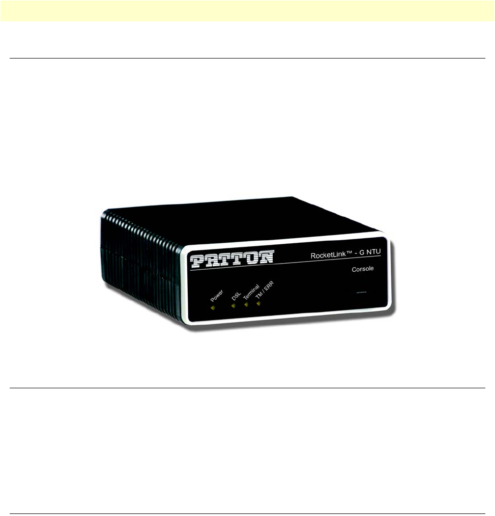
Figure 1. RocketLink-G 3088
Serial interface types
The Model 3088 versions listed below provide the following types of built-in serial interfaces:
•Model 3088/CA provides a V.35 interface on a DB-25 female connector.
•Model 3088/D provides an X.21 interface on a DB-15 female connector.
•Model 3088/T provides a T1/E1 interface on an RJ-48C receptacle.
•Model 3088/K provides a T1/E1 (G.703/G.704) interface on dual BNC connectors and an
RJ-48C receptacle.
Features
•Symmetrical high data-rate DSL (G.SHDSL)
•Data rates up to 4.6 Mbps in 64-kbps intervals for X.21 and V.35 models
•Data rates up to 2.048 Mbps in 64-kbps intervals for T1 and E1 models
•One of the following built-in serial interfaces:
-Serial V.35 (DCE only) — Model 3088/CA
-X.21 (selectable DCE or DTE) — Model 3088/D
-T1/E1 — Model 3088/K
-T1/E1 — Model 3088/T
•RS-232 console port for management and configuration
Power input connector 16
Model 3088 Series User Manual 1 • General information
•Built-in testing and diagnostics
•RocketLink Plug ‘n’ Play for easy installations
•Interoperable with other Patton G.SHDSL modems
•Configurable as remote (CP) units
•Configurable as central (CO) units to operate back-to-back
•Front-panel status indicators
•CE marked
Power input connector
The RocketLink-G comes with an AC or DC power supply. (See section “Power and power supply specifica-
tions” on page 73.)
•The power connection to the NTU is a 2.5 mm barrel receptacle with the center conductor positive
(see figure 2).
•Rated voltage: 5 VDC
Rated current: 1
A
Figure 2. Power connection barrel receptacle 5 VDC diagram
External AC universal power supply
For additional specifications, see section “Power and power supply specifications” on page 73.
•Output from power supply: 5 VDC, 2 A
•Input to power supply: universal input 100–240 VAC 50/60 Hz 0.3A
The external AC adaptor shall be a listed limited power source
that incorporates a disconnect device and shall be positioned
within easy reach of the operator. Ensure that the AC power
cable meets all applicable standards for the country in which it is
to be installed, and that it is connected to a wall outlet which has
earth ground.
5 VDC
CAUTION

Power input connector 17
Model 3088 Series User Manual 1 • General information
External 48 VDC power supply
Refer to section “Power and power supply specifications” on page 73 for additional specifications.
•Input
-Rated voltage: 36–60 VDC
-Rated current: 0.25 A DC
-3-pin locking connector, 3.5 mm pitch
-Transient over-voltage protection, 100VDC at 2 ms
•Output
-Rated voltage: 5 VDC ± 5%, 5W
-Rated current; 1 A DC
-6-inch cable terminated with 2.5 mm barrel plug, center positive
The external DC adaptor shall be a listed limited power source
that incorporates a disconnect device and shall be positioned
within easy reach of the operator. The interconnecting cables
shall be rated for the proper voltage, current, anticipated tem-
perature, flammability, and mechanical serviceability
CAUTION

18
Chapter 2 Configuration
Chapter contents
Introduction..........................................................................................................................................................19
Software (CLI) configuration ..........................................................................................................................19
Hardware (DIP-switch) configuration .............................................................................................................19
Configuring the DIP switches .........................................................................................................................22
System reset mode ...........................................................................................................................................23
Software upgrades .....................................................................................................................................23
Configuration reset to factory defaults .......................................................................................................23
DIP switch settings .........................................................................................................................................23
DIP switch settings for RocketLink-G models 3088/CA and 3088/D .............................................................24
S1-1 through S1-7: Data Rate (RocketLink-G models 3088/CA and 3088/D) .........................................25
S1-8: TX Clock (RocketLink-G models 3088/CA and 3088/D) ...............................................................27
S2-2: Line Probe (Models 3088/CA and D) ..............................................................................................27
S2-3: Annex A/B (Models 3088/CA and D) ..............................................................................................27
S2-4 through S2-5: Clock Mode (Models 3088/CA and D) ......................................................................27
X.21 operation. ................................................................................................................................... 28
S2-6: DTE Loops (RocketLink-G models 3088/CA only) ........................................................................28
DIP switch settings for RocketLink-G models 3088/K and 3088/T ................................................................29
S1-1 through S1-6: TimeSlots & Data Rate (RocketLink-G Models 3088/K and 3088/T) .......................30
S1-7 and S1-8: Line Build Out (Models 3088/K and 3088/T) ..................................................................31
S2-2 Line Code (Models 3088/K and 3088/T) .........................................................................................31
S2-3: Annex A/B (Models 3088/K and 3088/T) .......................................................................................31
S2-4 through S2-5: Clock Mode (Models 3088/K and 3088/T)) ..............................................................31
S2-6 through S2-8: Line Type (Models 3088/K and 3088/T) ...................................................................32
Console ...........................................................................................................................................................32
Help Commands .......................................................................................................................................35
System Configuration Commands ............................................................................................................35
System Status Commands .........................................................................................................................36
DSL Configuration Commands ................................................................................................................36
DSL Status Command ..............................................................................................................................37
DSL Clear Errcntrs Command ..................................................................................................................37
T1/E1 Configuration Commands .............................................................................................................37
T1/E1 Status Commands ..........................................................................................................................38
Remote Console ..............................................................................................................................................38
Example Command Line Interface Session ................................................................................................38
RocketLink Plug ‘n’ Play .................................................................................................................................39
Introduction 19
Model 3088 Series User Manual 2 • Configuration
Introduction
You can configure the RocketLink-G (see figure 3) in one of two ways:
•Software configuration using command line interface (CLI) via the console port
•Hardware configuration via DIP switches
Figure 3. RocketLink-G (Model 3088/D shown)
Software (CLI) configuration
To use software configuration you must set all the DIP switches to the ON position before powering-up the
RocketLink-G. When all the DIP switches are set to ON the RocketLink-G will operate in software-configura-
tion mode. When set for software-configuration mode the RocketLink-G will read any configuration data pre-
viously saved to FLASH memory during system power-up. If no configuration data was previously saved to
FLASH, then the RocketLink-G will load the factory-default configuration from FLASH memory. After
power-up, you may use console commands or the Embedded Operations Channel (EOC) to modify the con-
figuration parameters.
Hardware (DIP-switch) configuration
To use DIP-switch configuration you must first set the DIP switches to a position other than all OFF or all ON
before powering-up the RocketLink-G. When all the DIP switches are set to any position other than all OFF or
all ON the RocketLink-G will operate in hardware (DIP-switch)-configuration mode. In DIP-switch-configu-
ration mode the RocketLink-G will read the DIP-switch settings during system startup and configure itself
according to the switch settings.
Once you power-up the RocketLink-G in DIP-switch mode it will operate in DIP-switch mode until powered-
down. When operating in DIP-switch mode you cannot change any configuration settings:
•Changing the DIP switch settings while the device is running will not modify the operating configuration
because the RocketLink-G only reads the DIP switches during system startup.
•If you attempt to modify the configuration by issuing console commands, the device will not execute your
commands. Instead, the RocketLink-G will respond with a message indicating the device is operating in
DIP-switch-configuration mode.

Introduction 20
Model 3088 Series User Manual 2 • Configuration
•If you attempt to modify any configuration parameters via the EOC (by changing (EOC variables), the
RocketLink-G will not execute your changes.
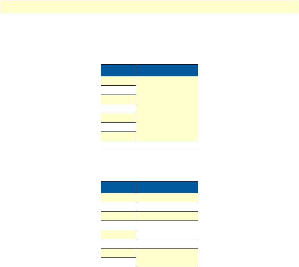
Table 2 lists the Model 3088’s configurable parameters.
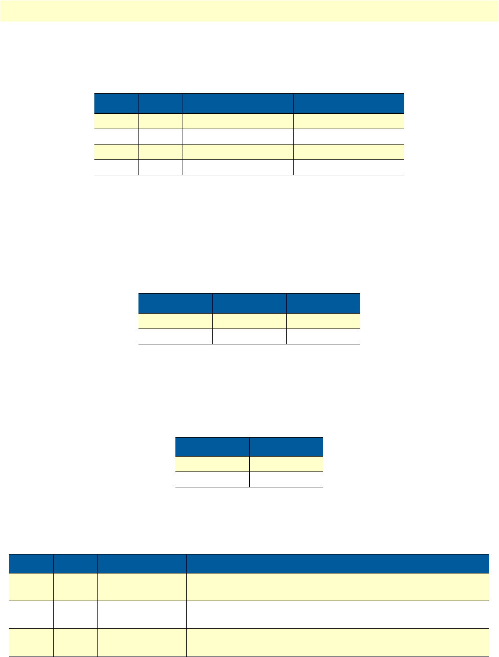
Table 2. RocketLink-G configurable parameters
Parameter Description Possible Values
Password The password used to login to the console. Character strings 1–9
characters long.
Circuit ID The circuit ID used to identify the unit. Character string 1–64
characters long.
Front Panel
Switches
If the device is populated with front panel switches, they can be
used to start and stop test modes. If they are disabled, however,
the front panel switch settings will be ignored.
Enabled or Disabled
DTE Loops
(model C)
The V.35 interface can request LALs and RDLs using its RRDL and
RLAL pins. If DTE loops are disabled, requests for loopbacks on
these pins will be ignored.
Enabled or Disabled
TX Clock
(models C, A & D)
Defines where (V.35 or X.21) serial transmit data is sampled in
relation to the TX clock: on the falling edge (normal) or the rising
edge (inverted) of the TX clock.
Normal or Inverted
DSL Data Rate/
Timeslots
Defines the number of DSL timeslots. The DSL data rate is calculated
by the equation: data rate = DSL timeslots x 64k. This value also
defines the maximum serial/T1/E1 data rate.
1–72
Serial/T1/E1
Timeslots
Defines the total number of serial/T1/E1 timeslots utilized. This value
must be less than or equal to DSL timeslots.
1–72 (V.35)
1–72 (X.21)
1–24 (T1)
1–32 (E1)
Timeslot
Mapping
(models K & T)
Defines T1/E1–to–DSL timeslot mapping. By default defined/utilized
DSL timeslots are mapped to the first n data–bearing timeslots on the
T1/E1 line. Line type determines which timeslots are data–bearing:
T1–Unframed: 1–24
a
T1–SF: 1–24
a
T1–ESF: 1–24
a
E1–Unframed: 0–31
E1–Fractional: 1–31
E1–CRC: 1–31
E1–MF: 1–15,17–31
E1–CRCMF: 1–15,17–31
Line Type
(models K & T)
Defines the framing format of the T1 or E1 line. T1–Unframed
a
T1–SF (D4)
a
T1–ESF
a
E1–Unframed
(Clear Channel
G.703)
E1–Fractional
E1–CRC
E1–Multiframe
E1–CRC & Multiframe

Introduction 21
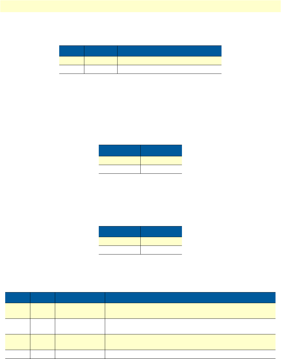
Model 3088 Series User Manual 2 • Configuration
Line Code
(models K & T)
Selects line coding for the T1 or E1 line. AMI
HDB3 (E1 only)
B8ZS (T1 only)
Line Build Out
(models K & T)
Selects wave form used on the T1 or E1 line. Pulse–75 Ohm(E1)
Pulse–120 Ohm (E1)
0.0 dB (T1)
-7.5 dB (T1)
-15.0 dB (T1)
-22.5 dB (T1)
RX Equalizer
(models K & T)
When enabled, this feature removes signal distortion introduced on
the T1 or E1 cable.
Enabled (select for
long–haul link).
Disabled (select for
short–haul link). Long
haul LBO (line build-
out) is defined by
ANSI T1.403).
Pass Framing
(models K & T)
When enabled, the RocketLink-G transparently passes framing infor-
mation (T1 F-bit or E1 TS0) over the DSL link to the remote T1/E1 net-
work.
Enabled or Disabled.
Must always be
enabled for T1.
Pass Alarms
(models K & T)
When enabled, the RocketLink-G passes alarms detected on one T1/
E1 network over the DSL link to the remote T1/E1 network.
Enabled or Disabled
Clock Mode Defines the clock source operation for both DSL and serial/T1/E1
ports as follows. Internal: the on–board oscillator in the 3088 pro-
vides clock for both serial/T1/E1 and DSL lines. External: the
serial/T1/E1interface provides clock for the DSL line. Receive
Recover: the DSL interface provides clock for the serial/T1/
E1 line.
Internal
External
Receive Recover
Annex The G.991.2 Annex. A or B
Line Probe When this special Patton feature is enabled, the 3088 will set the
DSL data rate to the best rate in the 3–36 timeslot range that both
NTUs can support. Enable for rate adaptive applications.
Enabled or Disabled
Loopback The 3088 provides both a local loopback (LAL) and a remote
loopback (RDL). This can be used to troubleshoot problems.
OFF, LAL, or RDL
Pattern The 3088 provides an internal PRBS pattern generator and detec-
tor that can be used to run BER tests without external equipment.
The patterns offered are 511 and 511 with errors.
OFF, 511, or 511E
DSL Error Monitor
Maximum Intervals
The number of errors allowed in an interval before considering
the interval errored. A value of 0 disables the error monitor.
0–255
Table 2. RocketLink-G configurable parameters (Continued)
Parameter Description Possible Values
Introduction 22
Model 3088 Series User Manual 2 • Configuration
Configuring the DIP switches
The Model 3088 is equipped with two sets of DIP switches, which you can use to configure the RocketLink-G for a
broad range of applications. This section describes switch locations and discusses the configuration options available.
Note
By default, the RocketLink-G’s DIP switches are all set to “ON” so the
NTU can be configured via RocketLink Plug ‘n’ Play from a 3096RC. If
that is how you will be configuring the NTU, skip ahead to section “Con-
sole” on page 32. Otherwise, read the following sections to manually config-
ure the DIP switch settings.
The two sets of DIP switches are externally accessible from the underside of the Model 3088 (see figure 4).
Figure 4. Underside of Model 3088 showing location of DIP switches
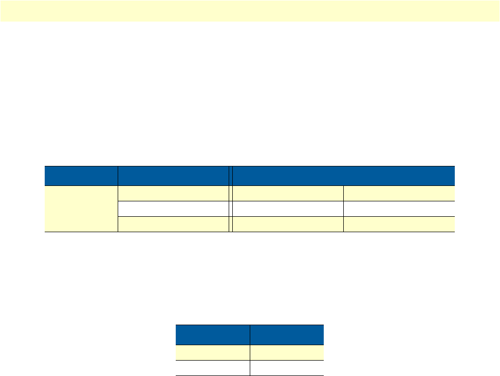
DSL Error Monitor
Interval Time
The length, in seconds, of an interval. 1–255
DSL Error Monitor
Interval Count
The number of errored intervals allowed before restarting the DSL
link.
1–255
DSL Error Monitor
Total Intervals
The number of intervals to inspect before disabling the error mon-
itor.
0–255
DSL Error Monitor
Startup Delay
The length, in seconds, to wait after DSL link comes up before
enabling the error monitor.
0–255
a. For T1 operation, pass framing must be enabled (see Pass Framing parameter for details).
Table 2. RocketLink-G configurable parameters (Continued)
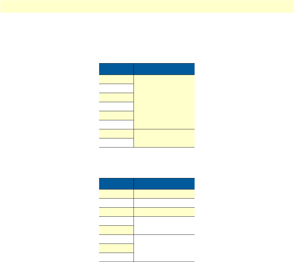
Parameter Description Possible Values
G.703/G.704 T
est Modes
Model 1194E Single Mode Fiber - Quad G.703/G.704 Modem
12345678
ON
S1
12345678
ON
S2
1 2 3 4 5 6 7 8
ON
1 2 3 4 5 6 7 8
ON
S1
S2
3088 C/D Models
G.703/G.704 T
est Modes
Model 1194E Single Mode Fiber - Quad G.703/G.704 Modem
12345678
ON
S1
12345678
ON
S2
1 2 3 4 5 6 7 8
ON
1 2 3 4 5 6 7 8
ON
S1
S2
3088 K/T Models
RocketLink-G NTU
RocketLink-G NTU
Introduction 23
Model 3088 Series User Manual 2 • Configuration
The two sets of DIP switches on the underside of the Model 3088 are referred to as S1 and S2. As shown in
figure 5, DIP switch orientation with respect to ON and OFF positions is consistent for all switches.
Figure 5. Close-up of configuration switches (all sets are identical appearance)
System reset mode
To enter system reset mode, switch all DIP switches to the OFF position and power cycle the unit. You can use
a VT100 emulator configured for 19,200 kbps/1 stop bit/ no parity/ XON-XOFF flow control to access the
console. Upon restart, you will see the message “Reset Mode”.
System reset mode provides two functions:
•Software upgrades
•Configuration reset to factory defaults
Software upgrades
The software is upgraded by waiting for the Reset Mode message. Then, the user can send an Intel HEX file
supplied by Patton. After the VT100 emulator has finished sending this file, the 3088 will respond with a mes-
sage stating how many errors were detected. The user may then set the DIP switches to the desired configura-
tion and power cycle the unit to run the upgraded software.
Configuration reset to factory defaults
To recover from a forgotten password, the user may reset the unit to its factory configuration. After seeing the
Reset Mode message, the user should type the ‘*’ key. This will result in a ‘:’ prompt. At the prompt, the user
should enter the command reset. This will restore the unit to the factory configuration. The unit can then be
restarted with the settings in place.
DIP switch settings
You can configure the 3088 by setting the DIP switches to the desired positions before you power up the Rock-
etLink-G. If the DIP switches are set to anything other than all OFF or all ON, the RocketLink-G will operate
in DIP switch configuration mode. Once the device is powered up and operating in DIP switch configuration
mode, you cannot change configuration by any method until you power it down again.
OFF
ON
1 2 3 4 5 6 7 8
ON
Introduction 24
Model 3088 Series User Manual 2 • Configuration
DIP switch settings for RocketLink-G models 3088/CA and 3088/D
An overview of the RocketLink-G DIP switch functions for Models 3088/CA and 3088/D is provided in
table 3 and table 4. The detailed switch settings are shown in following tables.
Table 3. Model 3088/CA and 3088/D - S1 DIP-Switch Functions
Position Function
S1-1 Data Rate
S1-2
S1-3
S1-4
S1-5
S1-6
S1-7
S1-8 TX Clock
Table 4. Model 3088/CA and 3088/D - S2 DIP-Switch Functions
Position Function
S2-1 Reserved
S2-2 Line Probe
S2-3 Annex
S2-4 Clock Mode
S2-5
S2-6 DTE Loops
S2-7 Reserved
S2-8

Introduction 25
Model 3088 Series User Manual 2 • Configuration
S1-1 through S1-7: Data Rate (RocketLink-G models 3088/CA and 3088/D)
Switches S1-1 through S1-7 define both the DSL data rate and the serial data rate.
Table 5. S1-1 through S1-7 Data Rate DIP switch settings
S1-1 S1-2 S1-3 S1-4 S1-5 S1-6 S1-7 Data Rate (kbps)
OFF ON ON ON ON ON ON 64
ON OFF ON ON ON ON ON 128
OFF OFF ON ON ON ON ON 192
ON ON OFF ON ON ON ON 256
OFF ON OFF ON ON ON ON 320
ON OFF OFF ON ON ON ON 384
OFF OFF OFF ON ON ON ON 448
ON ON ON OFF ON ON ON 512
OFF ON ON OFF ON ON ON 576
ON OFF ON OFF ON ON ON 640
OFF OFF ON OFF ON ON ON 704
ON ON OFF OFF ON ON ON 768
OFF ON OFF OFF ON ON ON 832
ON OFF OFF OFF ON ON ON 896
OFF OFF OFF OFF ON ON ON 960
ON ON ON ON OFF ON ON 1024
OFF ON ON ON OFF ON ON 1088
ON OFF ON ON OFF ON ON 1152
OFF OFF ON ON OFF ON ON 1216
ON ON OFF ON OFF ON ON 1280
OFF ON OFF ON OFF ON ON 1344
ON OFF OFF ON OFF ON ON 1408
OFF OFF OFF ON OFF ON ON 1472
ON ON ON OFF OFF ON ON 1536
OFF ON ON OFF OFF ON ON 1600
ON OFF ON OFF OFF ON ON 1664
OFF OFF ON OFF OFF ON ON 1728
ON ON OFF OFF OFF ON ON 1792
OFF ON OFF OFF OFF ON ON 1856
ON OFF OFF OFF OFF ON ON 1920
OFF OFF OFF OFF OFF ON ON 1984
ON ON ON ON ON OFF ON 2048
OFF ON ON ON ON OFF ON 2112
ON OFF ON ON ON OFF ON 2176
OFF OFF ON ON ON OFF ON 2240
ON ON OFF ON ON OFF ON 2304

Introduction 26
Model 3088 Series User Manual 2 • Configuration
OFF ON OFF ON ON OFF ON 2368
ON OFF OFF ON ON OFF ON 2432
OFF OFF OFF ON ON OFF ON 2496
ON ON ON OFF ON OFF ON 2560
OFF ON ON OFF ON OFF ON 2624
ON OFF ON OFF ON OFF ON 2688
OFF OFF ON OFF ON OFF ON 2752
ON ON OFF OFF ON OFF ON 2816
OFF ON OFF OFF ON OFF ON 2880
ON OFF OFF OFF ON OFF ON 2944
OFF OFF OFF OFF ON OFF ON 3008
ON ON ON ON OFF OFF ON 3072
OFF ON ON ON OFF OFF ON 3136
ON OFF ON ON OFF OFF ON 3200
OFF OFF ON ON OFF OFF ON 3264
ON ON OFF ON OFF OFF ON 3328
OFF ON OFF ON OFF OFF ON 3392
ON OFF OFF ON OFF OFF ON 3456
OFF OFF OFF ON OFF OFF ON 3520
ON ON ON OFF OFF OFF ON 3584
OFF ON ON OFF OFF OFF ON 3648
ON OFF ON OFF OFF OFF ON 3712
OFF OFF ON OFF OFF OFF ON 3776
ON ON OFF OFF OFF OFF ON 3840
OFF ON OFF OFF OFF OFF ON 3904
ON OFF OFF OFF OFF OFF ON 3968
OFF OFF OFF OFF OFF OFF ON 4032
ON ON ON ON ON ON OFF 4096
OFF ON ON ON ON ON OFF 4160
ON OFF ON ON ON ON OFF 4224
OFF OFF ON ON ON ON OFF 4288
ON ON OFF ON ON ON OFF 4352
OFF ON OFF ON ON ON OFF 4416
ON OFF OFF ON ON ON OFF 4480
OFF OFF OFF ON ON ON OFF 4544
ON ON ON OFF ON ON OFF 4608
Table 5. S1-1 through S1-7 Data Rate DIP switch settings (Continued)
S1-1 S1-2 S1-3 S1-4 S1-5 S1-6 S1-7 Data Rate (kbps)
Introduction 27
Model 3088 Series User Manual 2 • Configuration
S1-8: TX Clock (RocketLink-G models 3088/CA and 3088/D)
S2-2: Line Probe (Models 3088/CA and D)
Line probe is a mechanism that determines the highest rate (192K to 2304K) that the DSL link can reliably
support. This takes place during training. The DSL rate will be set to the rate that line probe determines. Note
that both the CO and CPE unit must have line probe enabled for it to take effect.
Line probe could be used to determine the best rate the line will support, and then the user could set the units
for that rate and disable line probe so that the rate won’t change without the user’s knowledge.
S2-3: Annex A/B (Models 3088/CA and D)
Annex A is typically used in North American-like networks, whereas Annex B is typically used in European-
like networks. The different annexes specify different PSD (power spectral density) masks because of the differ-
ence in T1 and E1 PSDs.
S2-4 through S2-5: Clock Mode (Models 3088/CA and D)
The RocketLink-G can operate in one of three clock modes: internal, network, or receive-recover.
Table 6. S1-8 TX Clock DIP switch settings
S1-8 Setting Description
ON Normal TD sampled on falling edge of TX clock.
OFF Inverted TD sampled on rising edge of TX clock.
Table 7. S2-2 Line Probe Switch Settings
S2-2 Line Probe
ON Disabled
OFF Enabled
Table 8. S2-3 Annex Type settings
S2-3 Annex
ON A
OFF B
Table 9. S2-4 and S2-5 Clock Mode Settings
S2-4 S2-5 Clock Mode Description
ON ON Internal The on-board oscillator in the 3088 provides clock for both serial
and DSL lines.
OFF ON Network 3088 uses the RX clock from the serial interface as the clock for the
DSL link.
ON OFF Receive-Recover 3088 uses the RX clock from the DSL line as the clock for the serial
interface.
OFF OFF Reserved
Introduction 28
Model 3088 Series User Manual 2 • Configuration
X.21 operation. There are a few things to note about clock modes and X.21 operation.
-One X.21 modem must be set to Receive-Recover. The other X.21 modem must be set to either Internal or
External/Network clock mode.
-The X.21 modem that is configured as Receive-Recover must be DCE.
-The X.21 modem that is configured as Internal must also be DCE, but if it is an External/Network clock,
then the modem must be configured as DTE.
S2-6: DTE Loops (RocketLink-G models 3088/CA only)
The V.35 interface provides two pins, one to request an LAL and the other to request an RDL. If DTE loops
are enabled, the 3088/CA will start a local loopback or a remote loopback when these pins are asserted. If DTE
loops are disabled, these requests will be ignored.
Table 10. X.21 Clocking
CPE-Side Modem CO-Side Modem
Modem’s
X.21
Orientation
Receive-Recover Internal External/Network
DCE DCE x
DCE xDTE
Table 11. S2-6 V.35 Loopback settings
S2-6 Setting
ON Enabled
OFF Disabled
Introduction 29
Model 3088 Series User Manual 2 • Configuration
DIP switch settings for RocketLink-G models 3088/K and 3088/T
An overview of the RocketLink-G DIP switch functions for Models 3088/K (E1) and 3088/T (T1) is provided
in table 12 and table 13.
Table 12. Model 3088/K and 3088/T S1 DIP-Switch Functions
Position Function
S1-1 Timeslots
S1-2
S1-3
S1-4
S1-5
S1-6
S1-7 Line Build Out
S1-8
Table 13. Model 3088/K and 3088/T S2 DIP-Switch Functions
Position Function
S2-1 Reserved
S2-2 Line Code
S2-3 Annex
S2-4 Clock Mode
S2-5
S2-6 Line Type
S2-7
S2-8

Introduction 30
Model 3088 Series User Manual 2 • Configuration
S1-1 through S1-6: TimeSlots & Data Rate (RocketLink-G Models 3088/K and 3088/T)
Switches S1-1 through S1-6 define the number of timeslots utilized, and thus the data rate, on both the T1/E1
line and the DSL line. G.991.2 specifies G.SHDSL data rates beginning at 192 kbps. In compliance with the
G.991.2 specification, the RocketLink-G will only set the number of DSL timeslots at a value greater than or
equal to 3, regardless of the setting for T1/E1 timeslots
Table 14. S1-1 through S1-6 Timeslots & DSL Data Rate DIP switch settings
S1-1 S1-2 S1-3 S1-4 S1-5 S1-6 Number of Timeslots Data Rate (kbps)
OFF ON ON ON ON ON 164
ON OFF ON ON ON ON 2128
OFF OFF ON ON ON ON 3192
ON ON OFF ON ON ON 4256
OFF ON OFF ON ON ON 5320
ON OFF OFF ON ON ON 6384
OFF OFF OFF ON ON ON 7448
ON ON ON OFF ON ON 8512
OFF ON ON OFF ON ON 9576
ON OFF ON OFF ON ON 10 640
OFF OFF ON OFF ON ON 11 704
ON ON OFF OFF ON ON 12 768
OFF ON OFF OFF ON ON 13 832
ON OFF OFF OFF ON ON 14 896
OFF OFF OFF OFF ON ON 15 960
ON ON ON ON OFF ON 16 1024
OFF ON ON ON OFF ON 17 1088
ON OFF ON ON OFF ON 18 1152
OFF OFF ON ON OFF ON 19 1216
ON ON OFF ON OFF ON 20 1280
OFF ON OFF ON OFF ON 21 1344
ON OFF OFF ON OFF ON 22 1408
OFF OFF OFF ON OFF ON 23 1472
ON ON ON OFF OFF ON 24 1536
OFF ON ON OFF OFF ON 25 1600
ON OFF ON OFF OFF ON 26 1664
OFF OFF ON OFF OFF ON 27 1728
ON ON OFF OFF OFF ON 28 1792
OFF ON OFF OFF OFF ON 29 1856
ON OFF OFF OFF OFF ON 30 1920
OFF OFF OFF OFF OFF ON 31 1984
ON ON ON ON ON OFF 32 2048
Introduction 31
Model 3088 Series User Manual 2 • Configuration
S1-7 and S1-8: Line Build Out (Models 3088/K and 3088/T)
Switches S1-7 and S1-8 define the shape of the waveform on the T1 or E1 line, as shown in table 15.
Note
75 Ohms corresponds to the BNC connectors on Model 3088/K.
120 Ohms corresponds to the T1/E1 (RJ-45) interface on Models 3088/K
and 3088/T.
S2-2 Line Code (Models 3088/K and 3088/T)
Switch S2-2 defines the T1 or E1 network line coding.
S2-3: Annex A/B (Models 3088/K and 3088/T)
Annex A is typically used in North American-like networks, whereas Annex B is typically used in European-
like networks. The different annexes specify different PSD (power spectral density) masks because of the differ-
ence in T1 and E1 PSDs.
S2-4 through S2-5: Clock Mode (Models 3088/K and 3088/T))
The RocketLink-G can operate in one of three clock modes: internal, network, or receive-recover.
Table 15. S1-7 – S1-8: Line Build Out Settings
S1-7 S1-8 Line Build Out (E1) Line Build Out (T1)
ON ON Pulse-75 Ohm 0.0dB
OFF ON Pulse-120 Ohm -7.5 dB
ON OFF Not Applicable -15.0dB
OFF OFF Not Applicable -22.5dB
Table 16. S2-2 Line Code Switch Settings
S2-2 T1 Line Code E1 Line Code
ON AMI AMI
OFF B8ZS HDB3
Table 17. S2-3 Annex Type settings
S2-3 Annex
ON A
OFF B
Table 18. S2-4 and S2-5 Clock Mode Settings
S2-4 S2-5 Clock Mode Description
ON ON Internal The on-board oscillator in the 3088 provides clock for both T1/E1
and DSL lines.
OFF ON Network 3088 uses the RX clock from the T1/E1 interface as the clock for
the DSL link.
ON OFF Receive-Recover 3088 uses the RX clock from the DSL interface as the clock for the
T1/E1 line.
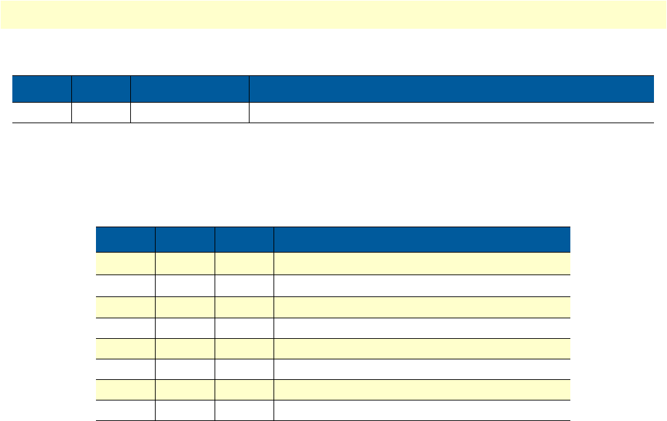
Introduction 32
Model 3088 Series User Manual 2 • Configuration
S2-6 through S2-8: Line Type (Models 3088/K and 3088/T)
The RocketLink-G has two different line types, T1 and E1. T1 has three different settings, and E1 has five dif-
ferent settings.
Console
The 3088 offers a console command line interface. To access the console, use a VT100 emulator configured to
19,200 kbps, 1 stop bit, no parity, and XON-XOFF flow control. Log into the unit using the default pass-
word. No username will be needed.
Note
For software release 2.1.2, log in with the default password patton.
For software release 2.1.3, log in with the default password superuser.
Through the console, the following variables can be configured:
•Password: The password used to login to the console.
•Circuit ID: The circuit ID communicated to other units via EOC. EOC (Embedded Operations Channel)
is an out-of-band channel specified in the G.991.2 standard for SHDSL. We use standard EOC messages
for our remote loopback. The 3088 also supports proprietary EOC messages that allow a 3096RC to con-
figure it.
•Clock Mode: The following options are available:
-Internal: The internal oscillator in the 3088 provides the clock to both the serial/T1/E1 and
DSL interfaces.
-Network: The T1/E1 interface provides the clock for the DSL interface (T1/E1 only).
OFF OFF Reserved
Table 19. S2-6 through S2-8 Line Type Settings
S2-6 S2-7 S2-8 Line Type
ON ON ON T1-Unframed
a
a. For T1 operation, pass framing must be enabled (see Pass Framing param-
eter in
table 2
on page 20 for details).
OFF ON ON T1-SuperFrame
a
ON OFF ON T1-ExtendedSuperFrame
a
OFF OFF ON E1-Unframed (G.703 Clear Channel)
ON ON OFF E1-Structured (G.704)
OFF ON OFF E1-CRC
ON OFF OFF E1-Multiframe
OFF OFF OFF E1-CRC Multiframe
Table 18. S2-4 and S2-5 Clock Mode Settings
S2-4 S2-5 Clock Mode Description

Introduction 33
Model 3088 Series User Manual 2 • Configuration
-External: The serial interface provides the clock for the DSL interface (V.35, X.21). It must be set to DTE
for the X.21 interface.
-Receive Recover: The 3088 recovers the clock from the DSL interface and provides it to the serial/T1/
E1 interface.
•Data Rate: Both the serial/T1/E1 and DSL data rates are set by specifying the number of 64k timeslots.
•Pass Framing: Must be enabled for T1. For E1, the entire TS0 time slot is passed. When E1 is configured
for CAS (Multiframe), the entire TS0 time slot and all of TS16 are both passed.
•Pass Alarms: When Passed Framing is enabled, the alarms are always passed, even if Pass Alarms is disabled.
When Passed Framing is disabled, you can pass alarms by enabling Pass Alarms.
•Rx Equalizer: This can be enabled to remove distortion introduced in the T1/E1 cable.
•Line Type: The following framing formats are available:
-T1-Unframed: Pass Framing must be enabled.
-T1-SF: Superframe (D4) framing.
-T1-ESF: Extended superframe.
-E1-Unframed: G.703 Clear Channel
-E1-Fractional: G.703/G.704 fractional.
-E1-CRC: Includes CRC multiframe.
-E1-Multiframe: Includes channel associated signalling (CAS).
-E1-CRC & Multiframe: Includes CRC and CAS multiframe.
•Line Code: The following line codes are available:
-AMI: Alternate Mark Inversion.
-HDB3: High Density Bipolar 3 (E1 only).
-B8ZS: Bit 8 Zero Substitution (T1 only).
•Line Build Out: The following line build outs are available:
-Pulse-75 (E1 only)
-Pulse-120 (E1 only)
-0.0 dB (T1 only)
--7.5 dB (T1 only)
--15.0 dB (T1 only)
--22.5 dB (T1 only)
•Annex: Either G.991.2 Annex A or Annex B.
•DSL Error Monitor Max Interval Errors: The number of errors allowed in an interval before considering
the interval errored. A value of ‘0’ disables the DSL error monitor.
•DSL Error Monitor Interval Time: The length in seconds of an interval.

Introduction 34
Model 3088 Series User Manual 2 • Configuration
•DSL Error Monitor Interval Count: The number of errored intervals allowed before restarting the DSL
link.
•DSL Error Monitor Total Intervals: The number of intervals to inspect before disabling the error moni-
tor.
•DSL Error Monitor Startup Delay: The length in seconds to wait after the DSL link is established before
starting the error monitor.
•Test Modes: Loopbacks (LAL or RDL) and PRBS (pseudo-random binary sequence) BER tests (511 or
511 with errors)
•Line Probe: Enable or disable Line Probe for rate adaptive applications.
The following status information is available through the command line interface:
•LEDs: Which software controlled LEDs are currently on.
•FPSW Settings: What the front panel switches are set to (if the unit is populated with them).
•Configuration Mode: Whether the 3088 is configured by DIP switches or software.
•DSL Link State: In Progress, Success, Deactivated, or Idle.
•DSL Sync State: Out of Sync, Acquiring Sync, In Sync, or Losing Sync.
Note
DSL Link State vs. DSL Sync State—The DSL link state describes whether
the DSL is training (in progress), linked (success), deactivated (we don’t have
an option to deactivate the modem, so the user should not see this), or idle.
The DSL sync state describes whether no sync words have been found (out
of sync), there are no sync word errors (in sync), or whether we are transi-
tioning from out of sync to in sync (acquiring sync) or vice versa (losing
sync). Typically, when the link is training, the sync state goes from out of
sync to acquiring sync to in sync.
•DSL Actual Rate: The actual rate at which the DSL link is running (minus DSL overhead).
•DSL Line Condition: Good or Poor.
•Noise Margin Ratio: the maximum tolerable increase in external noise power that still allows for BER of
less than 1x 10–
7
.
•DSL Error Counters: The following error counters are available:
-CRC
-LOSW (Loss of Sync Word)
-TX FIFO Full
-TX FIFO Empty
-TX FIFO Slip
-TX Stuff
-RX FIFO Full

Introduction 35
Model 3088 Series User Manual 2 • Configuration
-RX FIFO Empty
-RX FIFO Slip
•T1/E1 Loss of Signal: Active or Inactive.
•T1/E1 Frame Sync: Searching or Found.
•T1/E1 Frame Errors: Yes or No.
•T1/E1 Buffer Slips: Yes or No.
•Alarms: RED, YELLOW, BLUE. Active or Inactive.
•T1/E1 Error Counters: The following error counters are available:
-Line Code Violations
-Path Code Violations
-Errored Seconds
-Severely Errored Seconds
-Severely Errored Frame Seconds
-Unavailable Seconds
-Controlled Slip Seconds
-Line Errored Seconds
-Bursty Errored Seconds
-Degraded Minutes
Help Commands
The following commands are provided to help the user find the correct command:
•help: Lists all the commands that the console recognizes.
•system help: Lists all the commands that start with system that the console recognizes.
•system set help: Lists all the commands that start with system set that the console recognizes.
•system show help: Lists all the commands that start with system show that the console recognizes.
•dsl help: Lists all the commands that start with dsl that the console recognizes.
•dsl set help: Lists all the commands that start with dsl set that the console recognizes.
•dsl show help: Lists all the commands that start with dsl show that the console recognizes.
•dsl show errcntr help: Lists all the commands that start with dsl show errcntr that the console recognizes.
•t1e1 help: Lists all the commands that start with t1e1 that the console recognizes.
•t1e1 set help: Lists all the commands that start with t1e1 set that the console recognizes.
•t1e1 show help: Lists all the commands that start with t1e1 show that the console recognizes.

Introduction 36
Model 3088 Series User Manual 2 • Configuration
System Configuration Commands
The following commands allow the user to configure the system:
•system set password <password>: Sets the system password.
•system set circuitid <circuitid>: Sets the circuit ID.
•system set clockmode <internal|external/network|receiverecover>: Sets the clock mode. Internal clock
mode means the 3088 provides the clock to both the DSL and the serial/T1/E1 interface. External clock
mode means the 3088 uses the serial/T1/E1 transmit clock as its DSL transmit clock (V.35 only). Receive
recover clock mode means that the 3088 uses the DSL receive clock as its DSL transmit clock and as the
serial/T1/E1 receive clock.
Note
X.21 External Clock Mode—The X.21 interface expects the DCE to pro-
vide the clock used for both transmitting data and for sampling receive data.
When the 3088/D is set as a DCE, it may be used in internal or receive
recover clock modes. The DSL generates a clock that is provided to the X.21
interface.
When the 3088/D is a DTE, it may be used in external clock mode. The
X.21 interface needs to provide the clock. This clock is used by the DSL to
sample the serial data and also to update the receive data.
The 3088 is set for either DCE or DTE by flipping the daughter-card. The
3088 is a DCE if DCE points away from the serial interface toward the front
of the 3088. Note that this is different than the 3086/D.
The following commands allow the user to view the current system configuration:
•system show config: Shows the configuration of the entire system, including DSL and serial/T1/E1 lines.
Any changes to the system configuration or the DSL configuration will be lost on the next power cycle unless
the changes are saved. The command system save config is used to save the changes.
System Status Commands
The following commands show system status:
•system show status: Shows the following system status information: LEDs, DSL test mode, front panel
switch settings, DSL link state, and configuration mode.
DSL Configuration Commands
The following commands are used to configure the DSL:
•dsl set timeslots <1–24 (t1) | 32 (e1) | 72 (v.35, x.21)>: Sets the number of timeslots. For T1/E1 NTU’s,
the number of T1/E1 timeslots is set simultaneously. The T1/E1 timeslot mapping will be set to the
default. The data rate is calculated by the equation: data-rate = #timeslots x 64k.
•dsl set annex <a|b>: Set the annex.
•dsl set lineprobe <enabled|disabled>: Enable or disable line probe.
•dsl set loopback <off|lal|rdl>: Start or stop loopbacks.
•dsl set pattern <off|511|511e>: Start or stop PRBS generator and BER meter.

Introduction 37
Model 3088 Series User Manual 2 • Configuration
•DSL Error Monitor
The DSL error monitor inspects intervals to see if they have met the error threshold (maxint). If the error mon-
itor finds a certain number (intcnt) of intervals that meet or exceed the error threshold, it will restart the DSL
link. The error monitor will wait (startdelay) seconds after the DSL link comes up before it begins monitoring
errors. After the startup delay, it will check the number of errors that have occurred during each (inttime) sec-
onds to see if they meet the error threshold. The error monitor inspects (totint) intervals before it stops.
Note
Setting maxint to 0 disables the error monitor and setting totint to 0 causes
the error monitor to run continuously.
The following commands configure the error monitor:
•dsl set errmon maxint <maxint>: Sets the number of errors allowed in an interval causes it to be consid-
ered an errored interval. If this is set to ‘0’, then the error monitor is disabled.
•dsl set errmon inttime <inttime>: Sets the length of each interval.
•dsl set errmon intcnt <intcnt>: Sets the number of errored intervals that causes the DSL link to restart.
•dsl set errmon totint <totint>: Sets the number of intervals to inspect for errors before disabling the error
monitor. If this is set to ‘0’, then the error monitor will run continuously.
•dsl set errmon startdelay <startdelay>: Sets the number of seconds to wait after the DSL link comes up
before the error monitor starts inspecting intervals.
Changing the data rate (dsl set timeslots), the clock mode (system set clockmode), the Annex (dsl set
annex), or Line Probe (dsl set lineprobe), or the DSL error monitor settings will not take effect on the DSL
link until the link restarts. The dsl start command restarts the DSL link.
DSL Status Command
The dsl show status command shows the following DSL status information: link state, sync state, link speed,
error counters, line condition, noise margin, and test mode status.
DSL Clear Errcntrs Command
The dsl clear errcntrs command clears the error counters.
T1/E1 Configuration Commands
t1e1 set linetype <t1-unframed|t1-sf|t1-esf|e1-unframed|e1-fractional|e1-crc|e1-mf|e1-crcmf>
Select the T1 or E1 framing format to use.
t1e1 set linecode <ami|hdb3|b8zs>
Select the line code to use. HDB3 can only be used for E1 line types, and B8ZS can only be used for T1
line types.
Startup Delay Interval 1 Interval 2 …Interval totint
?startdelay⇒?inttime⇒?inttime⇒?inttime⇒?inttime⇒

Introduction 38
Model 3088 Series User Manual 2 • Configuration
t1e1 set lbo <75ohm|120ohm|0.0|7.5|15.0|22.5>
Select the line build out. 75? and 120? can only be use for E1 line types. The others can only be used for T1
line types.
t1e1 set timeslots <1-32>
Specify the number of T1/E1 timeslots to map to DSL timeslots. E1 has a maximum of 32 timeslots and T1
has a maximum of 24 timeslots.
t1e1 set tsmap <tsmap>
Specify the T1/E1 timeslots to map to DSL timeslots. This is a string that can contain ranges (-) and groups (,).
For example, the string 2-4,8-9 will select timeslots 2, 3, 4, 8, and 9.
t1e1 set rxeq <enabled|disabled>
Enable or disable the Rx equalizer. This is usually only enabled for long haul applications.
t1e1 set passframing <enabled|disabled>
Specify whether or not to pass the f-bit transparently in T1 modes. This must be enabled for T1-
Unframed mode.
t1e1 set passalarms <enabled|disabled>
Specify whether to generate alarms on the remote unit when detected on the local unit.
T1/E1 Status Commands
t1e1 show status: Shows the active T1/E1 configuration, loss-of-signal and framing errors, alarms, and perfor-
mance statistics.
Remote Console
Provided that there is a DSL link to a second 3088, a user may login to the first 3088’s console and enter the
remote console command to access the second 3088’s console. Using this remote console feature, the user can
configure and query the status of the second 3088 from a remote location. When the user is finished with the
remote console, the logout command can be used to return to the local console.
Example Command Line Interface Session
password: ******
> system set circuitid “3088 Circuit ID”
> system set timeslots 3
> system set clockmode internal
> dsl set annex b
> dsl set lineprobe disabled
> system save config
> dsl start
> system show status
leds: power: on dsl: on tm/er: off
dsl test mode:
ber status: idle
errors: 0
time: 0
front panel switches: sw1: normal sw2: normal
dsl link state: success
configuration mode: software
> dsl show status
link state: success
sync state: in sync
link speed: 192k
error counters:
crc: 0
losw: 0

Introduction 39
Model 3088 Series User Manual 2 • Configuration
tx fifo full: 0
tx fifo empty: 0
tx fifo slip: 0
tx stuff: 0
rx fifo full: 0
rx fifo empty: 0
rx fifo slip: 0
line condition: good
noise margin: 3.5
> remote console
password: ******
> dsl clear errcntrs
> dsl show errcntrs
crc: 0
losw: 0
tx fifo full: 0
tx fifo empty: 0
tx fifo slip: 0
tx stuff: 0
rx fifo full: 0
rx fifo empty: 0
rx fifo slip: 0
> logout
exiting remote console
> dsl set loopback rdl
> dsl set pattern 511e
> dsl show testmode
ber status: in progress
errors: 42
time: 12
> dsl set pattern off
> dsl set loopback off
> logout
password:
RocketLink Plug ‘n’ Play
The RocketLink Plug ‘n’ Play feature allows ISPs, carriers and PTTs to quickly upgrade the link speed for a
customer without requiring a visit to re-configure the Customer Premise (CP) Model 3088. This feature also
allows service providers to set up all of the configurations at the Central Office (via the ForeFront AIS system)
before installing the stand alone units, saving time spent configuring or re-configuring DIP switches.
Note
RocketLink Plug ’n’ Play is only available when using a ForeFront Model
3096RC running software release 1.5.7 or later. Since the 3096RC is CO,
the RocketLink must be CP, which is the default.
The RocketLink Plug ‘n’ Play feature allows the user to configure the CP unit via the ForeFront Model
3096RC at the Central Office (CO). The stand alone unit at the Customer Premise (CP) site will automati-
cally configure itself to the DTE rate (Bandwidth Allocation) defined at the Model 3096RC. Other configura-
tion parameters may likewise be modified from their default setting.
Follow the instructions below to activate RocketLink Plug ‘n’ Play between CO (Model 3096RC and CP
(Model 3088) units:
•Set the Model 3096RC (CO) to either Internal or External clocking mode as defined by the application.
Introduction 40
Model 3088 Series User Manual 2 • Configuration
•Set the Model 3088 (CP) to “RocketLink Plug-and-Play CP” by setting S1 and S2 DIP switches in the ON
position as described in figure 6.
Figure 6. Typical RocketLink Plug ‘n’ Play Application
When the CO and CP units connect over DSL, the CP will enter a predefined default configuration (Receive
Recovered Clocking). During the negotiation process, the CO unit will configure the DTE rate/line rate on
the CP unit as defined by the settings of the CO unit.
3096RC
(CO)
3088
(CP)
DIP Switches all in ON position
DIP Switches or NMS configured
according to specific application
requirements
DSL Span

41
Chapter 3 RocketLink-G installation
Chapter contents
Installation ............................................................................................................................................................42
Connecting the twisted pair interface ..............................................................................................................42
Connecting the Model 3088/CA (V.35) serial interface ..................................................................................43
Connecting the Model 3088/CA (V.35) to a “DTE” device ......................................................................43
Connecting the Model 3088/CA (V.35) to a “DCE” device ......................................................................43
Connecting the Model 3088/D (X.21) serial interface ....................................................................................44
Connecting the Model 3088/D (X.21) to a “DCE” or “DTE” device .......................................................44
Opening the Case ......................................................................................................................................45
Connecting the Model 3088/K serial interface ................................................................................................46
Connecting the Model 3088/K to an E1 Network ....................................................................................46
Connect twisted pair (120 ohm) to E1 network ..............................................................................................47
Connecting dual coaxial cable (75 ohm) to E1 network ..................................................................................47
Connecting the Model 3088/T (T1) serial interface ........................................................................................48
Connect Twisted Pair (100 ohm) to T1 Network .....................................................................................48
Connecting power ...........................................................................................................................................49
External AC universal power supply ..........................................................................................................49
DC Power .................................................................................................................................................50
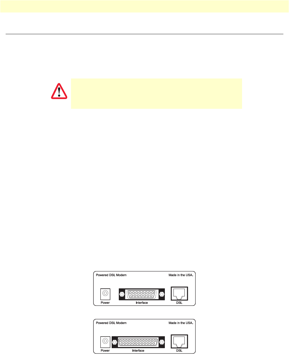
Installation 42
Model 3088 Series User Manual 3 • RocketLink-G installation
Installation
Once the Model 3088 is properly configured, it is ready to connect to the twisted pair interface, to the serial
port, and to the power source. This section tells you how to make these connections.
Connecting the twisted pair interface
The Model 3088 supports communication between two DTE devices as follows:
Using 24 AWG (0.5 mm) wire up to:
•32,000 feet (9.7 km) at 192 kbps
•18,500 feet (5.6 km) at 2.312 Mbps
Using 26 AWG (0.4 mm) wire up to:
•23,000 feet (7 km) at 192 kbps
•13,200 feet (4 km) at 2.312 Mbps
Two things are essential:
1. These units work in pairs. Both units at the end of the twisted pair DSL span must be set for the same
DTE rate—one unit set as CO, the other as CP.
2. To function properly, the Model 3088 needs one twisted pair of metallic wire. This twisted pair must be
unconditioned, dry, metallic wire, between 19 (0.9mm) and 26 AWG (0.4mm) (the higher number
gauges will limit distance). Standard dial-up telephone circuits, or leased circuits that run through signal
equalization equipment, or standard, flat modular telephone type cable, are not acceptable.
The RJ-45 connector on the Model 3088’s twisted pair interface is polarity insensitive and is wired for a two-
wire interface. The signal/pin relationships are shown in figure 7.
\
Figure 7. Model 3088 V.35/X.21 interfaces
The interconnecting cables shall be acceptable for external use
and shall be rated for the proper application with respect to volt-
age, current, anticipated temperature, flammability, and
mechanical serviceability.
CAUTION
3088/D (X.21, female DB-15)
3088/CA (V.35, female DB-25)
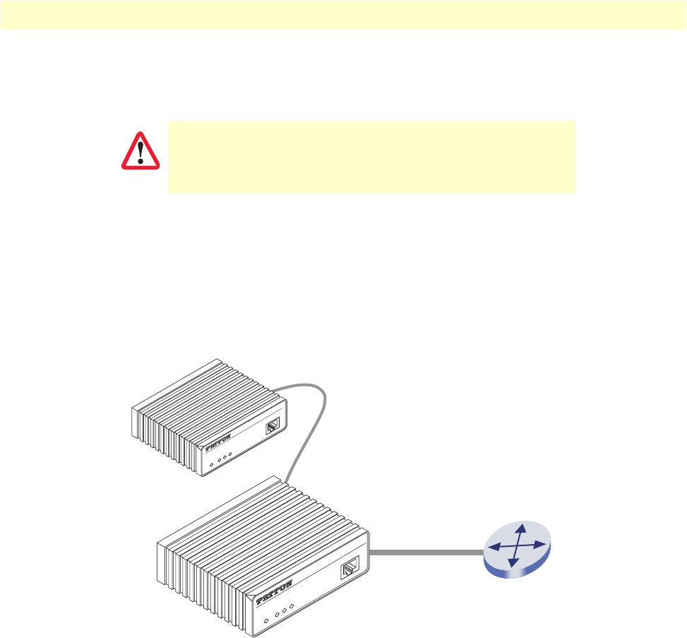
Installation 43
Model 3088 Series User Manual 3 • RocketLink-G installation
Connecting the Model 3088/CA (V.35) serial interface
Model 3088/CA supports V.35 serial port connections. This section describes how to connect the serial ports
to your V.35 equipment.
Connecting the Model 3088/CA (V.35) to a “DTE” device
The Model 3088/CA provides a V.35 DCE (data circuit terminating equipment) interface on an DB-25
female connector. As a DCE, this interface is designed to connect to DTE equipment, such as a router. When
connecting the V.35 interface of the Model 3088/CA to your DTE device, use a V.35 straight-through cable
(see figure 8). Appendix D on page 78 describes pin assignments and signal sources for the Model 3088/CA
V.35 interface. When purchasing or constructing an interface cable, refer to the pin diagrams in Appendix E
on page 80 as a guide.
Figure 8. Connecting the Model 3088/CA to V.35 Serial DTE
Connecting the Model 3088/CA (V.35) to a “DCE” device
The Model 3088/CA provides a V.35 DCE (data circuit terminating equipment) interface on an DB-25
female connector. As a DCE, this interface is designed to connect to DTE equipment, such as a router. How-
ever, connecting the 3088/CA to another DCE device, such as a multiplexer or G.703 E1 NTU, requires a tail-
The interconnecting cables shall be acceptable for external use
and shall be rated for the proper application with respect to volt-
age, current, anticipated temperature, flammability, and
mechanical serviceability.
CAUTION
Straight-Through Cable
DSL Span
ME233A (DCE)
Remote G.SHDSL NTU
V.35 Router (DTE)
DSL
Terminal
TM/ERR
Power
Console
DSL
Terminal
TM/ERR
Power
Console
RocketLink-G NTU
RocketLink-G NTU
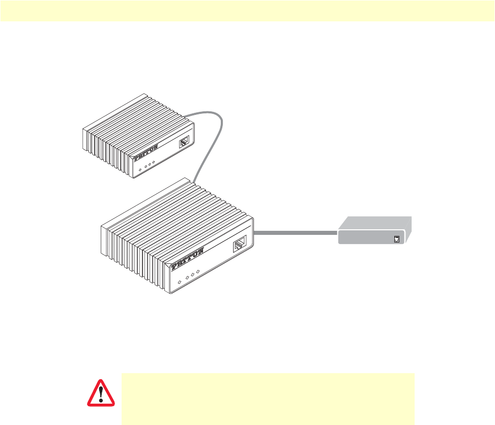
Installation 44
Model 3088 Series User Manual 3 • RocketLink-G installation
circuit cable. When connecting the V.35 interface of the Model 3088/CA to your DCE device (see figure 9),
use a V.35 tail circuit cable. Some applications may also require the installation of a tail-circuit buffer to
account for small differences in clock frequency between the 3088/CA and the V.35 DCE (multiplexer).
Figure 9. Connecting the Model 3088/CA to V.35 Serial DCE
Connecting the Model 3088/D (X.21) serial interface
Model 3088/D supports X.21 serial port connections. This section describes how to connect the serial ports to
your X.21 equipment.
Connecting the Model 3088/D (X.21) to a “DCE” or “DTE” device
The Model 3088/D provides an X.21 interface on a DB-15 female connector. The X.21 interface default con-
figuration is DCE for connection to DTE (data terminal equipment) such as a router. However, the X.21
interface on the Model 3088/D may be configured as DTE (data terminal equipment) for connection to DCE
The interconnecting cables shall be acceptable for external use
and shall be rated for the proper application with respect to volt-
age, current, anticipated temperature, flammability, and
mechanical serviceability.
Tail-circuit cable
DSL Span
Model 3088/CA (DCE)
Remote Model 3088
(DCE)
RocketLink™-G NTU
DSL
Terminal
TM/ERR
Power
Console
RocketLink™-G NTU
DSL
Terminal
TM/ERR
Power
Console
G.703 E1 NTU
CAUTION
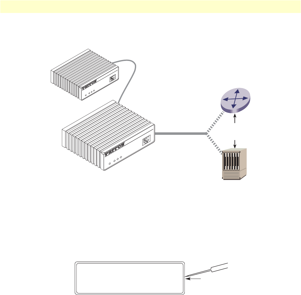
Installation 45
Model 3088 Series User Manual 3 • RocketLink-G installation
such as a modem or multiplexer. When connecting the X.21 interface of the Model 3088/D to your DTE or
DCE device, use an X.21 straight-through cable (See figure 10).
Figure 10. Connecting the Model 3088/D to X.21 DTE or DCE
To change the DCE/DTE orientation from the default position (DCE), you must open the case Model
3088/D case.
Opening the Case
To open the Model 3088/D case, insert a flat head screw driver into an open slot on both sides of the case, as
in figure 11. Twist the screw driver head slightly and the top half of the case will separate from the lower half,
as in figure 11. Be careful not to damage the PC-board mounted components.
Figure 11. Opening the 3088 case with a small screwdriver
Straight-Through 15-pin
D-Sub Cable
Model 3088/D (DCE or DTE)
DSL Span
Remote Model 3088
RocketLink™-G NTU
DSL
Terminal
TM/ERR
Power
Console
RocketLink™-G NTU
DSL
Terminal
TM/ERR
Power
Console
Router (DTE)
OR
Mux (DCE)

Installation 46
Model 3088 Series User Manual 3 • RocketLink-G installation
The DCE/DTE strap is located on the top side of the 3088/D pc board (See figure 12). The arrows on the top
of the strap indicate the configuration of the X.21 port (for example, if the DCE arrows are pointing toward
the DB-15 connector, the X.21 port is wired as a DCE). Change the DCE/DTE orientation by pulling the
strap out of its socket, rotating it 180°, then plugging the strap back into the socket. You will see that the
DCE/DTE arrows now point in the opposite directions, showing the new configuration of the X.21 port. To
close the case, fit the two halves together snugly and snap them back in place.
Figure 12. Setting the DCE/DTE Strap (X.21 only)
Connecting the Model 3088/K serial interface
Connecting the Model 3088/K to an E1 Network
The Model 3088/K supports E1 network connections. This section describes how to connect the network to
your Model 3088/K.
The interconnecting cables shall be acceptable for external use
and shall be rated for the proper application with respect to volt-
age, current, anticipated temperature, flammability, and
mechanical serviceability.
DCE/DTE Strap
DB-15 Connector
DCE
DTE
CAUTION

Installation 47
Model 3088 Series User Manual 3 • RocketLink-G installation
Connect twisted pair (120 ohm) to E1 network
The Model 3088/K is equipped with a single RJ-48C jack for connections to a 120 ohm twisted pair E1 net-
work interface. If your E1 network terminates via RJ-48C, use the diagram below and the table following it to
make the proper connections. The connector pinout and signals are shown in figure 13.
Figure 13. 120 Ohm RJ-48C E1 interface
Use the following connection diagram to connect the 120-ohm E1 network channel.
\
Figure 14. RJ-45 cable diagram for E1 connection
Connecting dual coaxial cable (75 ohm) to E1 network
The Model 3088/K is also equipped with dual female BNCs (TX and RX) for connection to a 75 ohm dual
coax E1 network interface. If your E1 network terminates via dual coaxial cable, use figure 15 to make the
proper connections.
The interconnecting cables shall be acceptable for external use
and shall be rated for the proper application with respect to volt-
age, current, anticipated temperature, flammability, and
mechanical serviceability.
1
2
3
4
5
6
7
8
1
2
3
4
5
6
7
8
(RX) Receive (Ring)
(RX) Receive (Tip)
Shield
(TX) Transmit (Ring)
(TX) Transmit (Tip)
Shield
No connection
No connection
Signal NameRJ-48C Jack
RJ-48C Cable (8-Wire)
E1 (G.703/G.704)
Network signal
3088/K
Signal Pin #
RX (Ring)
RX (Tip)
Shield
TX (Ring)
TX (Tip)
Shield
1
2
3
4
5
6
TX (Ring)
TX (Tip)
Shield
RX (Ring)
RX (Tip)
Shield
CAUTION
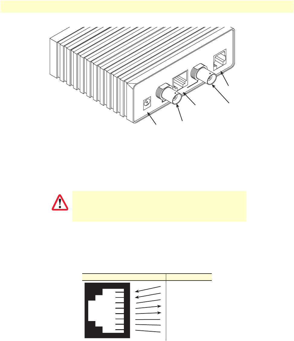
Installation 48
Model 3088 Series User Manual 3 • RocketLink-G installation
Figure 15. Model 3088/K rear panel
Connecting the Model 3088/T (T1) serial interface
The Model 3088/T supports T1 network connections. This section describes how to connect the network to
your Model 3088/T.
Connect Twisted Pair (100 ohm) to T1 Network
The Model 3088/T is equipped with a single RJ-48C jack for connection to a 100 ohm twisted-pair T1 net-
work interface. Use the diagram below and the table following it to make the proper connections. The connec-
tor pinout and signals are shown in figure 16.
Figure 16. 120 Ohm RJ-48C T1 interface
The interconnecting cables shall be acceptable for external use
and shall be rated for the proper application with respect to volt-
age, current, anticipated temperature, flammability, and
mechanical serviceability.
Made in the USA
Power
Power DSL
DSL
TX
Interface
RX
RX (75 Ohm)
(Data from
G.703/G.704
network)
TX (75 Ohm)
(Data to
G.703/G.704
network)
E1 interface
(120 Ohm)
Powered DSL Modem
CAUTION
1
2
3
4
5
6
7
8
1
2
3
4
5
6
7
8
(RX) Receive (Ring)
(RX) Receive (Tip)
Shield
(TX) Transmit (Ring)
(TX) Transmit (Tip)
Shield
No connection
No connection
Signal NameRJ-48C Jack

Installation 49
Model 3088 Series User Manual 3 • RocketLink-G installation
Use the following connection diagram to connect the 120 ohm E1 network channel.
Figure 17. RJ-45 cable diagram for T1 connection
Connecting power
External AC universal power supply
1. Connect the power cord from the AC socket to the IEC-320 power entry connector on the universal input
power supply.
2. Connect the barrel plug to the Power connector on the Model 3088.
Note
The Model 3088 powers up as soon as it is plugged into an AC outlet—there
is no power switch.
The external AC adaptor shall be a listed limited power source
that incorporates a disconnect device and shall be positioned
within easy reach of the operator. Ensure that the AC power
cable meets all applicable standards for the country in which it is
to be installed, and that it is connected to a wall outlet which has
earth ground.
RJ-48C Cable (8-Wire)
T1
Network signal
3088/T
Signal Pin #
RX (Ring)
RX (Tip)
Shield
TX (Ring)
TX (Tip)
Shield
1
2
3
4
5
6
TX (Ring)
TX (Tip)
Shield
RX (Ring)
RX (Tip)
Shield
CAUTION
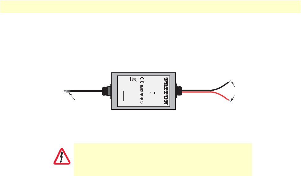
Installation 50
Model 3088 Series User Manual 3 • RocketLink-G installation
DC Power
The 36-60 VDC DC to DC adapter is supplied with the DC version of the Model 3088. The black and red
leads plug into a DC source (nominal 48VDC) and the barrel power connector plugs into the barrel power
supply jack on the 3088. (See Figure 18).
Figure 18. DC Power Supply
There are no user-servicable parts in the power supply section of
the Model 3088/C/D/K/T. Fuse replacement should only be
performed by qualified service personnel. See Chapter 8,
“Con-
tacting Patton for assistance”
on page 64.
To Power
Supply Jack To -48VDC
Source
-Vin
+Vin
SWITCHING POWER SUPPLY
MODEL : SYD1106-0505
INPUT : 36-60V 0.2A MAX
OUTPUT : +5V 1.0A
OUTPUT POWER : 5W MAX
S/N: G01234567890
MADE IN CHINA BY SUNNY
Black lead (-V
)
Red lead (+V)
Barrel power connector
WARNING

51
Chapter 4 Operation
Chapter contents
Introduction..........................................................................................................................................................52
Power-up ........................................................................................................................................................52
LED status monitors .......................................................................................................................................52
Power (Green) ...........................................................................................................................................52
DSL (Green) .............................................................................................................................................52
Link (Green) (Models K and T only) ........................................................................................................52
Term (Green) [Models C and D] ..............................................................................................................53
TM/ER (Red) ...........................................................................................................................................53
LOS (Red) [Models K and T] ...................................................................................................................53
Test modes ......................................................................................................................................................53
Loopbacks .................................................................................................................................................54
Patterns .....................................................................................................................................................54
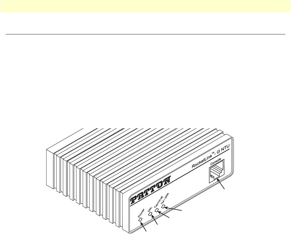
Introduction 52
Model 3088 Series User Manual 4 • Operation
Introduction
Once the Model 3088 is properly configured and installed, it should operate transparently. The following sec-
tions describe power-up, reading the LED status monitors, and using the built-in loopback test modes.
Power-up
To apply power to the Model 3088, first be sure that you have read section “Power input connector” on
page 16, and that the unit is connected to the appropriate power source. Power up the unit.
LED status monitors
There are four LEDs that provide feedback on the state of the unit. Figure 19 shows the location of the front
panel LEDs. Following figure 19 is a description of each LED’s function.
Figure 19. Model 3088/CA front panel
Power (Green)
The Power LED glows solid during normal operation. At startup, during the POST, the LED blinks once
every second. If the POST fails, the unit does not enter normal operation, and the LED blinks once every
0.4 seconds.
DSL (Green)
The DSL LED glows solid while a DSL link is established. While the DSL link is training it blinks once every
second.
Link (Green) (Models K and T only)
The Link LED indicates the status of the T1/E1 link. It is dark when it detects no signal. It blinks once per sec-
ond when it detects signal, but not valid framing. It glows solid when it detects valid framing.
DSL
Terminal
Consol
e
TM / ERR
Power
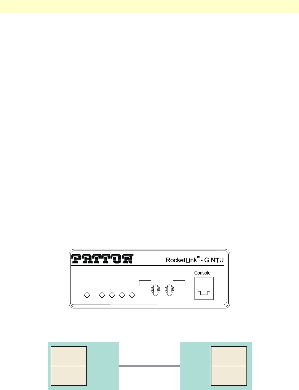
Introduction 53
Model 3088 Series User Manual 4 • Operation
Term (Green) [Models C and D]
The Term LED glows solid under the following circumstances:
•3088/CA with V.35 interface: If the serial interface has asserted DTR
•3088/D with the X.21 interface:
-Configured as DCE: Indicates that the “Control” signals have been asserted.
-Configured as DTE: Indicates that the “Indication” signals have been asserted
TM/ER (Red)
The TM/ER LED is used to indicate that a test mode is in progress or an error has been detected. It blinks
once every second while a test mode is starting. It glows solid while a test mode is in progress. It blinks once if
an error is detected either during a test mode, or in normal DSL operation.
LOS (Red) [Models K and T]
The LOS LED blinks once per second to indicate either framing errors or clock slips. Clock slips are often
caused by a mis-configured clock mode.
Test modes
The 3088 offers test modes in the form of loopbacks, PRBS pattern generators, and combinations of both.
This section discusses how the test modes work. The following 3088 models have toggle switches available on
the front panel for operating test modes:
•3088/CAS/E
•3088/DS/E
•3088/KS/E
•3088/TS/E
Figure 20. 3088/S Model Front Panel
Figure 21 is a block diagram of the Model 3088 with respect to test modes.
Figure 21. Model 3088 Block Diagram
Power
DSL
Link
TM/ERR
LOS
Test Modes
Local –
Normal –
Remote –
– 511E
– Normal
– 511
DSL
Framer
511 Pattern
Generator
511 BER
Meter
DSL
Framer 511 Pattern
Generator
511 BER
Meter
Line
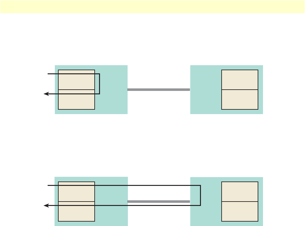
Introduction 54
Model 3088 Series User Manual 4 • Operation
Loopbacks
The 3088 supports both Local Analog Loopbacks (LAL) and Remote Digital Loopbacks (RDL). These can be
initiated either from the optional front panel switches or by the console command dsl set loopback
<off|lal|rdl>. The data path for the LAL is shown in figure 22.
.
Figure 22. Local Analog Loopback diagram
The data received from the serial interface is looped back before going out on the DSL line. Note that this
loopback occurs after the pattern generator/BER meter. This means that running a 511 pattern in conjunction
with an LAL should result in no error detected by the meter.
The data path for the RDL is shown in figure 23.
Figure 23. Remote Digital Loopback diagram
The RDL causes the remote unit to loop the data received from the DSL line back tow the DSL line.
Patterns
The 3088 can generate and detect 511 and 511 with Error patterns. These can be initiated either by the
optional front panel switches or by the console command dsl set pattern <off|511|511e>. When the pattern is
started, the DSL framer uses its internal 511 pattern generator for its DSL TX data instead of the data received
from the serial interface. Also, the framer’s internal BER Meter tries to detect a 511 pattern in the DSL
RX Data.
Because the BER Meter always runs when the pattern generator runs, the meter will detect errors if either the
pattern is not either looped back or the remote unit is not transmitting a 511 pattern.
One point to note is that the way errors are generated in the 511E pattern generates CRC errors. This can
cause the DSL error monitor to restart the link if the thresholds are set low enough.
DSL
Framer
511 Pattern
Generator
511 BER
Meter
DSL
Framer 511 Pattern
Generator
511 BER
Meter
Line
DSL
Framer
511 Pattern
Generator
511 BER
Meter DSL
Framer
511 Pattern
Generator
511 BER
Meter
Line

55
Chapter 5 Remote console operation
Chapter contents
Introduction..........................................................................................................................................................56
Establishing a Remote Console Session ...........................................................................................................56
How to Connect .......................................................................................................................................56
How to Disconnect ...................................................................................................................................57
Differences in Local and Remote Control Session Behavior ......................................................................58
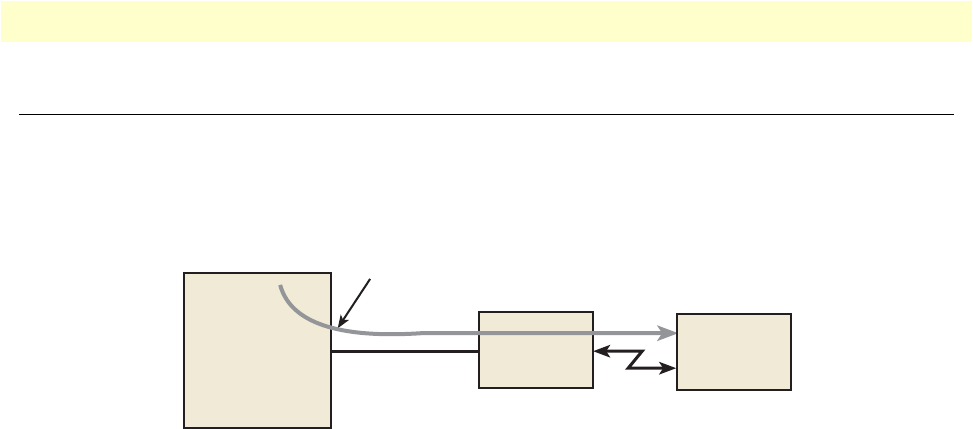
Introduction 56
Model 3088 Series User Manual 5 • Remote console operation
Introduction
The PC user (near-end) may configure and verify status of the remote 3088 (far-end) via a Remote Console
session. The PC user must log onto the 3088 (near-end) unit to establish a remote console session. Once done,
the remote 3088 (far-end) appears as a unit which is locally connected through the RS-232 console port. All
commands are transmitted over the G.SHDSL link in the EOC channel.
Figure 24. Remote control session diagram
Establishing a Remote Console Session
How to Connect
The following steps are to establish a connection to the remote 3088 (far-end) via Remote Console Session
(RCS):
1. Configure a terminal emulation program (e.g., Hyperterminal) on PC (near-end) for 19.2 kbps, 8 data
bits, no parity, 1 stop bit, no flow control. Connect it to the RS-232 console port of the 3088 (near-end).
2. At the password prompt, log in to the near-end Model 3088.
3. Ensure that a DSL link is established. You can verify an established DSL link by using the system show sta-
tus command or by checking that the DSL LED is solid green. Upon executing the show status com-
mand, the dsl link state is shown as success if the DSL link is established.
4. At the command prompt, enter the command remote console.
5. Wait for the message Console: Remote console connection established.
– If a DSL link is not established, or for some other reason the 3088 (far-end) does not respond in a rea-
sonable amount of time, the following message appears: Console: Remote console timed out trying to con-
nect. Enter the command remote console again.
– If 3088 (Far End) already has an active remote console session open, you will see the message Console:
Remote console connection request rejected. This can also happen if the remote 3088 (far-end) has an estab-
lished remote console session with the local 3088 (near-end) which has timed out.
6. Enter the password at the password prompt for the remote console session.
Note
The passwords for a local console session of the 3088 (near-end) and the
remote console session of the 3088 (far-end) should be different for the pur-
pose of security.
7. You should now be logged into the remote 3088 (far-end) via the remote console session. The communi-
cation with the remote 3088 (far-end) is essentially the same as having a local console connection.
RS-232
Remote Console Session (RCS)
DSL
PC
(Near End)
3088
(Near End)
3088
(Far End)
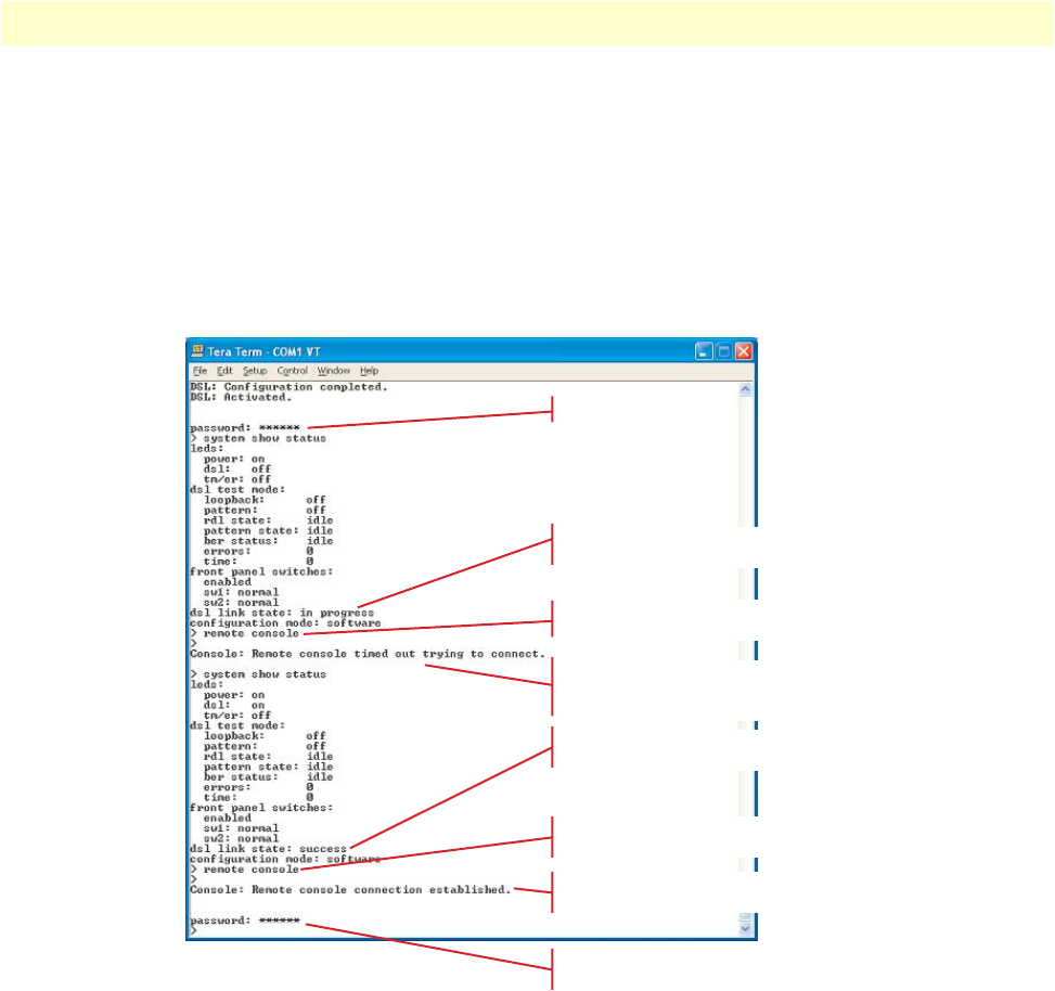
Introduction 57
Model 3088 Series User Manual 5 • Remote console operation
Note
The local or remote 3088 may be CO or CPE, as long as there is one of each.
Either the CO or CPE unit may accept a remote console connection.
Note
With a remote console session open, a user at PC (far-end) is blocked from
using the local console. Upon typing anything, the 3088 (far-end) sends a
message to the PC (far-end) stating Console: Remote console connection is open.
Figure 25 is a screenshot of opening a typical remote console session:
Figure 25. Opening a typical remote console session
How to Disconnect
The remote console session ends under any of the following conditions:
•The user enters the command logout
•A timeout period of 5 minutes elapses since the user has entered a command to the console.
•The DSL link drops.
Log in to 3088 (Near End)
system show status command
shows that DSL link is not up
remote console command requests a
remote console session on 3088 (Far End)
Message informs us that the 3088 (Far End) did not
respond and a remote
console session was not opened
system show status command shows
that the DSL link state is success
remote console command requests a
remote console session on 3088 (Far End)
Message informs us that we are now
connected to the 3088 (Far End) console
We can now enter commands on
the remote console
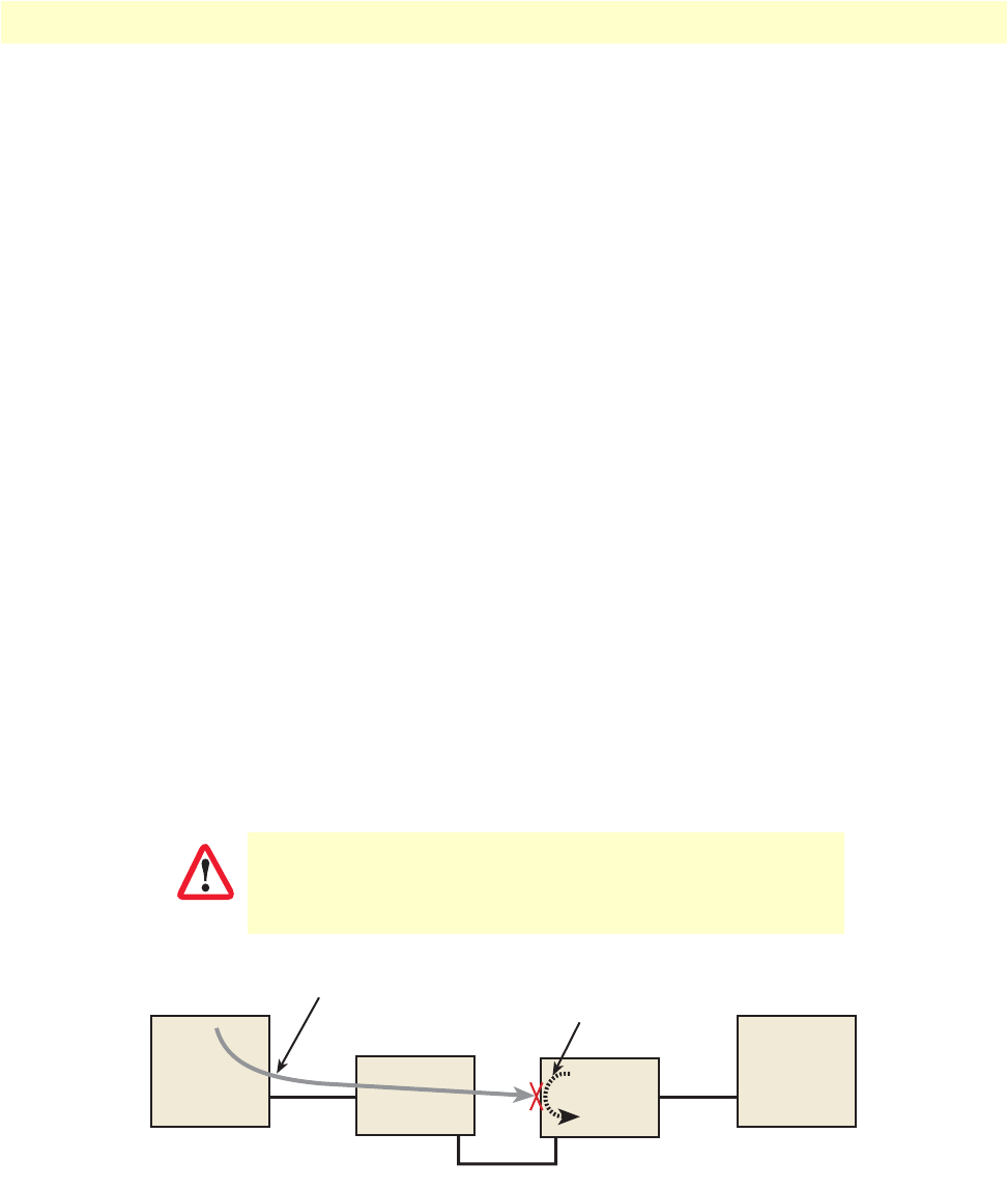
Introduction 58
Model 3088 Series User Manual 5 • Remote console operation
The response upon logging out of the remote console session with the command logout is Console: Remote con-
sole connection lost. The following is what is displayed upon a user’s logging out of a remote console session after
logging in.
> remote console
>
Console: Remote console connection established.
password: ******
> logout
Console: Remote console connection lost.
>
The timeout period is a fixed, non-configurable parameter of 5 minutes. If the remote 3088 (far-end) has
received no command within 5 minutes, it automatically terminates the RCS. Once the RCS is terminated, the
PC (far-end) can establish a local console session if desired. However if the PC (near-end) wishes to re-establish
a RCS, it is able to do so whether or not the PC (far-end) is in an active local session, because the RCS has pri-
ority over a local console session. If the PC (near-end) establishes an RCS while the PC (far-end) is on a local
session, the PC (far-end) is kicked off.
Differences in Local and Remote Control Session Behavior
Since the remote console session communication occurs over the G.SHDSL link’s EOC channel, some com-
mands via the RCS have unusual effects.
•system upgrade: Do not issue this command via an RCS. A system upgrade must be done via the local con-
sole connection. If you should accidentally issue this command over an RCS, the remote 3088 (far-end)
waits indefinitely for input (which is the system upgrade image) from the local console port of the 3088
(far-end). If this command is entered, 3088 (Far End) will have to be power-cycled.
Figure 26. Remote control session with LAL diagram
Do not attempt a software upgrade of the remote unit over the
Remote Control Session.
CAUTION
PC
(Near End) RS-232
Remote Console Session (RCS)
DSL
RS-232
LAL
3088
(Near End)
3088
(Far End)
PC
(Far End)

Introduction 59
Model 3088 Series User Manual 5 • Remote console operation
•dsl set loopback lal: Do not issue this command over the RCS to the far-end 3088. If the far-end goes into
LAL, the near-end and far-end 3088 NTUs can no longer communicate over the RCS.
Do not issue this command to a far-end unit. If you were to do
so, the near-end 3088 would no longer be able to communicate
with the far-end 3088.
CAUTION


Introduction 61
Model 3088 Series User Manual 6 • Software Upgrade
Introduction
The Model 3088 is software upgradeable through the console port. Software images will be available in Intel
Hex file format.
The software upgrade feature is available either by powering up the Model 3088 with all DIP switches set to
the OFF position, or by entering the system upgrade command on the command line interface. The software
upgrade takes approximately 5 minutes to complete. The 3088 will print ‘.’ to the screen while the software
upgrade is in process. When the software upgrade completes, it will print a message stating that it is complete
and the number of errors, if any, that occurred.
Errors may occur during the software upgrade if the image is corrupt or if there is a disruption in the console
port connection. The Model 3088 will print a message to the console port if it encounters any errors. In the
event of an error, the portions of the old image may have been overwritten, and the unit may not be able to
boot into operational mode. However, the unit may still boot into the software upgrade, so a new software
image can still be loaded to bring the unit back to an operational state.
Here is the software upgrade procedure:
1. Obtain the software image Hex file for the 3088.
2. Turn off the Model 3088.
3. Make a note of the current DIP switch settings, then set all DIP switches to the OFF position.
4. Turn on the Model 3088.
5. Configure HyperTerminal for 19.2 kbps, 8 bits, 1 stop bit, no parity, XON-XOFF.
6. Open Model 3088 Console (via HyperTerminal or other terminal emulation program).
>>Transfer
>>Send Text File…
>>Set “Files of Type:” to “All files (*.*)”
>>Select 033252Z.hex
7. When the transfer completes, turn off the Model 3088.
8. Set the DIP switches for the proper configuration.
9. Turn on the Model 3088. It now operates with the upgraded software.


Introduction 63
Model 3088 Series User Manual 7 • Reset configuration to factory defaults
Introduction
The configuration can be reset to factory defaults from the software reset mode. This allows a user to recover
from a forgotten password. To reset to the configuration, follow these steps:
1. Power down the unit.
2. Set all DIP switches to the OFF position.
3. Connect a PC to the Console port.
4. Open a VT100 terminal emulator (such as HyperTerminal). Configure the emulator for 19,200 kbps,
1 stop bit, no parity, X-ON X-OFF flow control.
5. Power up the unit. The terminal should display the following message: Reset Mode.
6. Type the ‘*’ key. You will see a ‘:’ prompt.
7. Type the command reset.
8. When the command completes, the unit has been reset to factory configuration.
9. Set the DIP switches to the desired configuration. Power cycle the unit to begin using the new software.

64
Chapter 8 Contacting Patton for assistance
Chapter contents
Introduction..........................................................................................................................................................65
Contact information..............................................................................................................................................65
Patton support headquarters in the USA .........................................................................................................65
Alternate Patton support for Europe, Middle East, and Africa (EMEA) ..........................................................65
Warranty Service and Returned Merchandise Authorizations (RMAs)...................................................................65
Warranty coverage ..........................................................................................................................................65
Out-of-warranty service .............................................................................................................................66
Returns for credit ......................................................................................................................................66
Return for credit policy .............................................................................................................................66
RMA numbers ................................................................................................................................................66
Shipping instructions ................................................................................................................................66

Introduction 65
Model 3088 Series User Manual 8 • Contacting Patton for assistance
Introduction
This chapter contains the following information:
•“Contact information”—describes how to contact Patton technical support for assistance.
•“Warranty Service and Returned Merchandise Authorizations (RMAs)”—contains information about the
warranty and obtaining a return merchandise authorization (RMA).
Contact information
Patton Electronics offers a wide array of free technical services. If you have questions about any of our other
products we recommend you begin your search for answers by using our technical knowledge base. Here, we
have gathered together many of the more commonly asked questions and compiled them into a searchable
database to help you quickly solve your problems.
Patton support headquarters in the USA
•Online support: available at www.patton.com
•E-mail support: e-mail sent to support@patton.com will be answered within 1 business day
•Telephone support: standard telephone support is available five days a week—from 8:00 am to
5:00 pm EST (1300 to 2200 UTC/GMT)—by calling +1 (301) 975-1007
•Fax: +1 (253) 663-5693
Alternate Patton support for Europe, Middle East, and Africa (EMEA)
•Online support: available at www.patton-inalp.com
•E-mail support: e-mail sent to support@patton-inalp.com will be answered within 1 business day
•Telephone support: standard telephone support is available five days a week—from 8:00 am to
5:00 pm CET (0900 to 1800 UTC/GMT)—by calling +41 (0)31 985 25 55
•Fax: +41 (0)31 985 25 26
Warranty Service and Returned Merchandise Authorizations (RMAs)
Patton Electronics is an ISO-9001 certified manufacturer and our products are carefully tested before ship-
ment. All of our products are backed by a comprehensive warranty program.
Note
If you purchased your equipment from a Patton Electronics reseller, ask your
reseller how you should proceed with warranty service. It is often more con-
venient for you to work with your local reseller to obtain a replacement.
Patton services our products no matter how you acquired them.
Warranty coverage
Our products are under warranty to be free from defects, and we will, at our option, repair or replace the prod-
uct should it fail within one year from the first date of shipment. Our warranty is limited to defects in work-
manship or materials, and does not cover customer damage, lightning or power surge damage, abuse, or
unauthorized modification.

Warranty Service and Returned Merchandise Authorizations (RMAs) 66
Model 3088 Series User Manual 8 • Contacting Patton for assistance
Out-of-warranty service
Patton services what we sell, no matter how you acquired it, including malfunctioning products that are no
longer under warranty. Our products have a flat fee for repairs. Units damaged by lightning or other catastro-
phes may require replacement.
Returns for credit
Customer satisfaction is important to us, therefore any product may be returned with authorization within 30
days from the shipment date for a full credit of the purchase price. If you have ordered the wrong equipment or
you are dissatisfied in any way, please contact us to request an RMA number to accept your return. Patton is
not responsible for equipment returned without a Return Authorization.
Return for credit policy
•Less than 30 days: No Charge. Your credit will be issued upon receipt and inspection of the equipment.
•30 to 60 days: We will add a 20% restocking charge (crediting your account with 80% of the purchase price).
•Over 60 days: Products will be accepted for repairs only.
RMA numbers
RMA numbers are required for all product returns. You can obtain an RMA by doing one of the following:
•Completing a request on the RMA Request page in the Support section at www.patton.com
•By calling +1 (301) 975-1007 and speaking to a Technical Support Engineer
•By sending an e-mail to returns@patton.com
All returned units must have the RMA number clearly visible on the outside of the shipping container. Please use
the original packing material that the device came in or pack the unit securely to avoid damage during shipping.
Shipping instructions
The RMA number should be clearly visible on the address label. Our shipping address is as follows:
Patton Electronics Company
RMA#: xxxx
7622 Rickenbacker Dr.
Gaithersburg, MD 20879-4773 USA
Patton will ship the equipment back to you in the same manner you ship it to us. Patton will pay the return
shipping costs.

67
Appendix A Compliance information
Chapter contents
Compliance ...........................................................................................................................................................68
EMC ...............................................................................................................................................................68
Safety ..............................................................................................................................................................68
PSTN Regulatory ............................................................................................................................................68
FCC Part 68 (ACTA) Statement ...........................................................................................................................68
Radio and TV Interference (FCC Part 15) ............................................................................................................69
Industry Canada Notice ........................................................................................................................................69
CE Declaration of Conformity..............................................................................................................................69
Authorized European Representative .....................................................................................................................70
Compliance 68
Model 3088 Series User Manual A • Compliance information
Compliance
EMC
•FCC Part 15, Class A
•EN55022, Class A
•EN55024
Safety
•UL 60950-1/CSA C22.2 N0. 60950-1
•IEC/EN60950-1 2nd edition
•AS/NZS 60950-1
•GOST-R
PSTN Regulatory
•ACTA TIA/EIA/IS-968 A5
•Industry Canada CS-03
•TBR12 & 13 (K and T models)
•AS/ACIF S016:2001 ( K and T models)
•AS/ACIF S043:2003
•-1979, expires 21.04.2011(3088/T/EUI)
•-1980, expires 21.04.2011(3088/K/EUI)
•-1981, expires 21.04.2011(3088/D/EUI)
•-1982, expires 21.04.2011(3088/CA/EUI)
FCC Part 68 (ACTA) Statement
This equipment complies with Part 68 of FCC rules and the requirements adopted by ACTA. On the bottom
side of this equipment is a label that contains—among other information—a product identifier in the format
US: AAAEQ##TXXXX. If requested, this number must be provided to the telephone company.
The method used to connect this equipment to the premises wiring and telephone network must comply with
the applicable FCC Part 68 rules and requirements adopted by the ACTA.
If this equipment causes harm to the telephone network, the telephone company will notify you in advance
that temporary discontinuance of service may be required. But if advance notice isn’t practical, the telephone
company will notify the customer as soon as possible. Also, you will be advised of your right to file a complaint
with the FCC if you believe it is necessary.
The telephone company may make changes in its facilities, equipment, operations or procedures that could
affect the operation of the equipment. If this happens, the telephone company will provide advance notice in
order for you to make necessary modifications to maintain uninterrupted service.

Radio and TV Interference (FCC Part 15) 69
Model 3088 Series User Manual A • Compliance information
If trouble is experienced with this equipment, for repair or warranty information, please contact our company.
If the equipment is causing harm to the telephone network, the telephone company may request that you dis-
connect the equipment until the problem is resolved.
Connection to party line service is subject to state tariffs. Contact the state public utility commission, public
service commission or corporation commission for information.
Radio and TV Interference (FCC Part 15)
This device generates and uses radio frequency energy, and if not installed and used properly-that is, in strict
accordance with the manufacturer’s instructions-may cause interference to radio and television reception. The
device has been tested and found to comply with the limits for a Class A computing device in accordance with
specifications in Subpart B of Part 15 of FCC rules, which are designed to provide reasonable protection from
such interference in a commercial installation. However, there is no guarantee that interference will not occur
in a particular installation. If the device does cause interference to radio or television reception, which can be
determined by disconnecting the unit, the user is encouraged to try to correct the interference by one or more
of the following measures: moving the computing equipment away from the receiver, re-orienting the receiving
antenna and/or plugging the receiving equipment into a different AC outlet (such that the computing equip-
ment and receiver are on different branches).
Industry Canada Notice
This equipment meets the applicable Industry Canada Terminal Equipment Technical Specifications. This is
confirmed by the registration number. The abbreviation, IC, before the registration number signifies that reg-
istration was performed based on a Declaration of Conformity indicating that Industry Canada technical spec-
ifications were met. It does not imply that Industry Canada approved the equipment.
This Declaration of Conformity means that the equipment meets certain telecommunications network protec-
tive, operational and safety requirements. The Department does not guarantee the equipment will operate to
the user's satisfaction. Before installing this equipment, users should ensure that it is permissible to be con-
nected to the facilities of the local telecommunications company. The equipment must also be installed using
an acceptable method of connection. In some cases, the company’s inside wiring associated with a single line
individual service may be extended by means of a certified connector assembly (telephone extension cord). The
customer should be aware that compliance with the above condition may not prevent degradation of service in
some situations. Repairs to some certified equipment should be made by an authorized maintenance facility
designated by the supplier. Any repairs or alterations made by the user to this equipment, or equipment mal-
functions, may give the telecommunications company cause to request the user to disconnect the equipment.
Users should ensure for their own protection that the ground connections of the power utility, telephone lines
and internal metallic water pipe system, are connected together. This protection may be particularly important
in rural areas.
CE Declaration of Conformity
Patton Electronics, Inc declares that this device is in compliance with the essential requirements and other rel-
evant provisions of Directive 1999/5/EC. The Declaration of Conformity may be obtained from Patton Elec-
tronics, Inc at www.patton.com/certifications.
The safety advice in the documentation accompanying this device shall be obeyed. The conformity to the
above directive is indicated by CE mark on the device.

Authorized European Representative 70
Model 3088 Series User Manual A • Compliance information
Authorized European Representative
D R M Green
European Compliance Services Limited.
Avalon House, Marcham Road
Abingdon,
Oxon OX14 1UD, UK

71
Appendix B Specifications
Chapter contents
Clocking modes.....................................................................................................................................................72
DTE rate...............................................................................................................................................................72
Serial interface .......................................................................................................................................................72
Serial connector.....................................................................................................................................................72
Diagnostics............................................................................................................................................................72
Status LEDs...........................................................................................................................................................72
Power (Green) ...........................................................................................................................................72
DSL (Green) .............................................................................................................................................72
Link (Green) (T1/E1 only) .......................................................................................................................72
Term (Green) ............................................................................................................................................73
TM/ER (Red) ...........................................................................................................................................73
Configuration........................................................................................................................................................73
Power and power supply specifications ..................................................................................................................73
External AC universal power supply ................................................................................................................73
External 48 VDC power supply ......................................................................................................................74
Transmission line ..................................................................................................................................................74
Line coding ...........................................................................................................................................................74
Line rates (DSL line) .............................................................................................................................................74
Line interface.........................................................................................................................................................74
G.SHDSL physical connection..............................................................................................................................74
Environment .........................................................................................................................................................74

Clocking modes 72
Model 3088 Series User Manual B • Specifications
Clocking modes
Internal, external (V.35 only), or receive recovered
DTE rate
All 64k steps from 64 to 4608 kbps
Serial interface
V.35 (Model 3088/CA), DCE orientation;
X.21 (Model 3088/D), DCE or DTE orientation depending on orientation of daughter board mounted on the
mother board.
E1 (Model 3088/K) presents G.703/G.704 interface. Either 75 Ohms (unbalanced) or 120 Ohms (balanced).
Pins 1 & 2 are Receive. Pins 4 & 5 are Transmit.
T1 (Model 3088/T) present T1 interface. Pins 1 & 2 are Receive. Pins 4 & 5 are Transmit.
Serial connector
D-Sub-25 Female (Model 3088/CA)
D-Sub-15 Female (Model 3088/D)
Dual BNC and RJ48C (Model 3088/K), strap selectable
RJ48C connector (Model 3088/T)
Diagnostics
V.52 compliant (511/511E) pattern generator and detector with error injection mode controlled by front-
panel switch. Local and Remote Loopback control either by a front-panel switch or from the DTE interface.
Status LEDs
Power (Green)
The Power LED glows solid during normal operation. At startup, during the POST, the LED blinks once
every second. If the POST fails, the unit does not enter normal operation, and the LED blinks once every
0.4 seconds.
DSL (Green)
The DSL LED glows solid while a DSL link is established. While the DSL link is training it blinks once every
second.
Link (Green) (T1/E1 only)
Solid green indicates valid T1/E1 framing. Flashing indicates signal being received, but the link has not yet
been established.
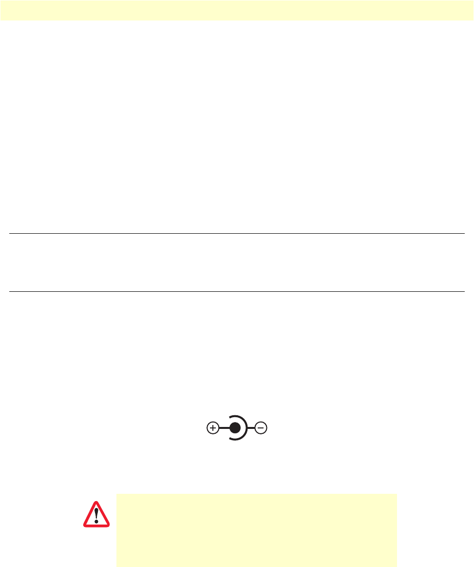
Configuration 73
Model 3088 Series User Manual B • Specifications
Term (Green)
The Term LED glows solid under the following circumstances:
•3088/CA with V.35 interface: If the serial interface has asserted DTR
•3088/D with the X.21 interface:
-Configured as DCE: Indicates that the “Control” signals have been asserted.
-Configured as DTE: Indicates that the “Indication” signals have been asserted
TM/ER (Red)
The Test Mode/Error (TM/ER) LED is used to indicate that a test mode is in progress or an error has been
detected. It blinks once every second while a test mode is starting. It glows solid while a test mode is in
progress. It blinks once if an error is detected either during a test mode, or in normal DSL operation.
Configuration
Configuration is done with either externally accessible DIP switches, CLI or through the EOC (Embedded
Operations Channel) from a Model 3096RC G.SHDSL concentration card.
Power and power supply specifications
The NTU comes with either an AC or DC power supply:
•The supply’s connection to the NTU is a 2.5 mm barrel receptacle with the center conductor positive.
•There is one fuse in the equipment rated at 250V, 500 mA, 2 sec.
•Rated voltage: 5 VDC
•Rated current: 1 A DC
Figure 27. Power connection barrel receptacle 5 VDC diagram
External AC universal power supply
•Output from power supply: 5 VDC, 2A
•Input to power supply: universal input 100–240 VAC 50/60 Hz 0.3A
The external AC adaptor shall be a listed limited power source
that incorporates a disconnect device and shall be positioned
within easy reach of the operator. Ensure that the AC power
cable meets all applicable standards for the country in which it is
to be installed, and that it is connected to a wall outlet which has
earth ground.
5 VDC
CAUTION
Transmission line 74
Model 3088 Series User Manual B • Specifications
External 48 VDC power supply
•Input
-Rated voltage: 36–60 VDC
-Rated current: 0.25 A DC
•Output
-Rated voltage: 5 VDC ± 5%, 5W
-Rated current: 1 A DC
-6-inch cable terminated with 2.5 mm barrel plug, center positive
•Isolation: 500 VDC
•Environment: 0–40°C; 5–95% relative humidity, non-condensing
Transmission line
Single Twisted Pair
Line coding
TC-PAM (Trellis Coded Pulse Amplitude Modulation)
Line rates (DSL line)
All nx64 rates from 64 kbps up to 4.6 Mbps
Line interface
Transformer coupled, 2500 VRMS isolation
G.SHDSL physical connection
RJ-45, 2-wire polarity insensitive pins 4 and 5
Environment
Operating temp: 32–122°F (0–50°C)
Humidity: 5–95% non-condensing
Altitude: 0–15,000 feet (0–4,600 meters)
The external DC adaptor shall be a listed limited power source
that incorporates a disconnect device and shall be positioned
within easy reach of the operator. The interconnecting cables
shall be rated for the proper voltage, current, anticipated tem-
perature, flammability, and mechanical serviceability
CAUTION

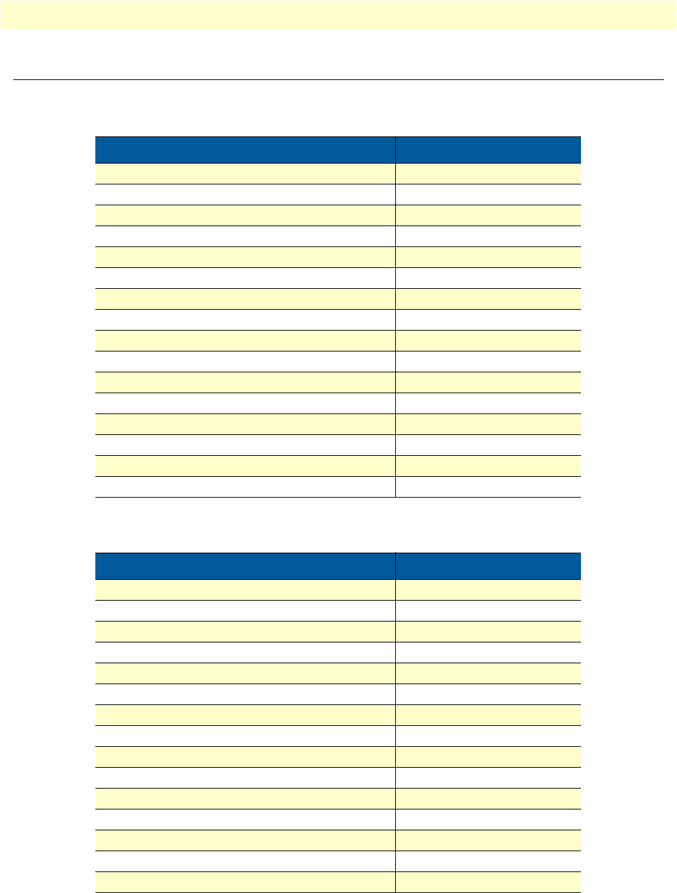
Factory default values for software-configurable parameters 76
Model 3088 Series User Manual C • Factory default values
Factory default values for software-configurable parameters
Table 20. 3088/CA and 3088/D
Parameter Default value
Clock Mode Receive-Recover
DSL Timeslots 31
Serial Timeslots 31
Tx Clock Normal
Circuit ID Patton Model 3088
Password superuser
Front Panel Switches Enabled
Annex B
Line Probe Disabled
Loopback Off
Pattern Off
DSL Error Monitor – Max Errors/Interval 3
DSL Error Monitor – Interval Time 1
DSL Error Monitor – Max Errored Intervals 3
DSL Error Monitor – Total Intervals 10
DSL Error Monitor – Startup Delay 5
Table 21. 3088/K
Parameter Default value
Clock Mode Receive-Recover
DSL Timeslots 31
T1/E1 Timeslots 31
T1/E1 Timeslot Map 1-31
T1/E1 Line Type E1 - Fractional
T1/E1 Line Code HDB3
T1/E1 Line Build Out 75 Ohm
T1/E1 Rx Equalizer Disabled
T1/E1 Pass Framing Disabled
T1/E1 Pass Alarms Disabled
Circuit ID Patton Model 3088
Password superuser
Front Panel Switches Enabled
Annex B
Line Probe Disabled
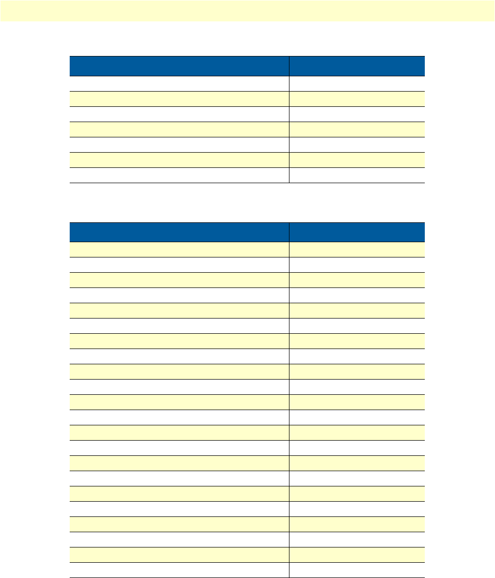
Factory default values for software-configurable parameters 77
Model 3088 Series User Manual C • Factory default values
Loopback Off
Pattern Off
DSL Error Monitor – Max Errors/Interval 3
DSL Error Monitor – Interval Time 1
DSL Error Monitor – Max Errored Intervals 3
DSL Error Monitor – Total Intervals 10
DSL Error Monitor – Startup Delay 5
Table 22. 3088/T
Parameter Default value
Clock Mode Receive-Recover
DSL Timeslots 24
T1/E1 Timeslots 24
T1/E1 Timeslot Map 1-24
T1/E1 Line Type T1 – ESF
T1/E1 Line Code B8ZS
T1/E1 Line Build Out 0.0 dB
T1/E1 Rx Equalizer Disabled
T1/E1 Pass Framing Disabled
T1/E1 Pass Alarms Disabled
Circuit ID Patton Model 3088
Password Superuser
Front Panel Switches Enabled
Annex A
Line Probe Disabled
Loopback Off
Pattern Off
DSL Error Monitor – Max Errors/Interval 3
DSL Error Monitor – Interval Time 1
DSL Error Monitor – Max Errored Intervals 3
DSL Error Monitor – Total Intervals 10
DSL Error Monitor – Startup Delay 5
Table 21. 3088/K (Continued)
Parameter Default value

Factory replacement parts and accessories 79
Model 3088 Series User Manual D • Factory replacement parts and accessories
Factory replacement parts and accessories
Model # Description
08055DCUI 100–240VAC (+5V ±5% reg. DC/2A) Universal Input Adapter
0805EUR European Power Cord CEE 7 (“A”)
0805UK United Kingdom Power Cord (“D”)
0805US American Power Cord (“K”)
0805AUS Australia/New Zealand Power Cord (“C”)
0805DEN Denmark Power Cord (“E”)
0805FR France/Belgium Power Cord (“F”)
0805IN India Power Cord (“G”)
0805IS Israel Power Cord (“H”)
0805JAP Japan Power Cord (“J”)
0805SW Switzerland Power Cord (“L”)
07M3088-UM User Manual
2-34F25M V.35 Gender Changer, M/34 female to DB-25 male
10-25M/35F-1 Cable, DB-25 Male to V.35 Female, 6 feet
10-25M/35M-1 Cable DB-25 Male to V.35 Male, 6 feet

80
Appendix E Interface pinouts
Chapter contents
RJ-11 non-shielded DSL port................................................................................................................................81
V.35 interface........................................................................................................................................................81
T1/E1 interface .....................................................................................................................................................81
X.21 interface ........................................................................................................................................................82
RS-232 console interface pin assignments..............................................................................................................82
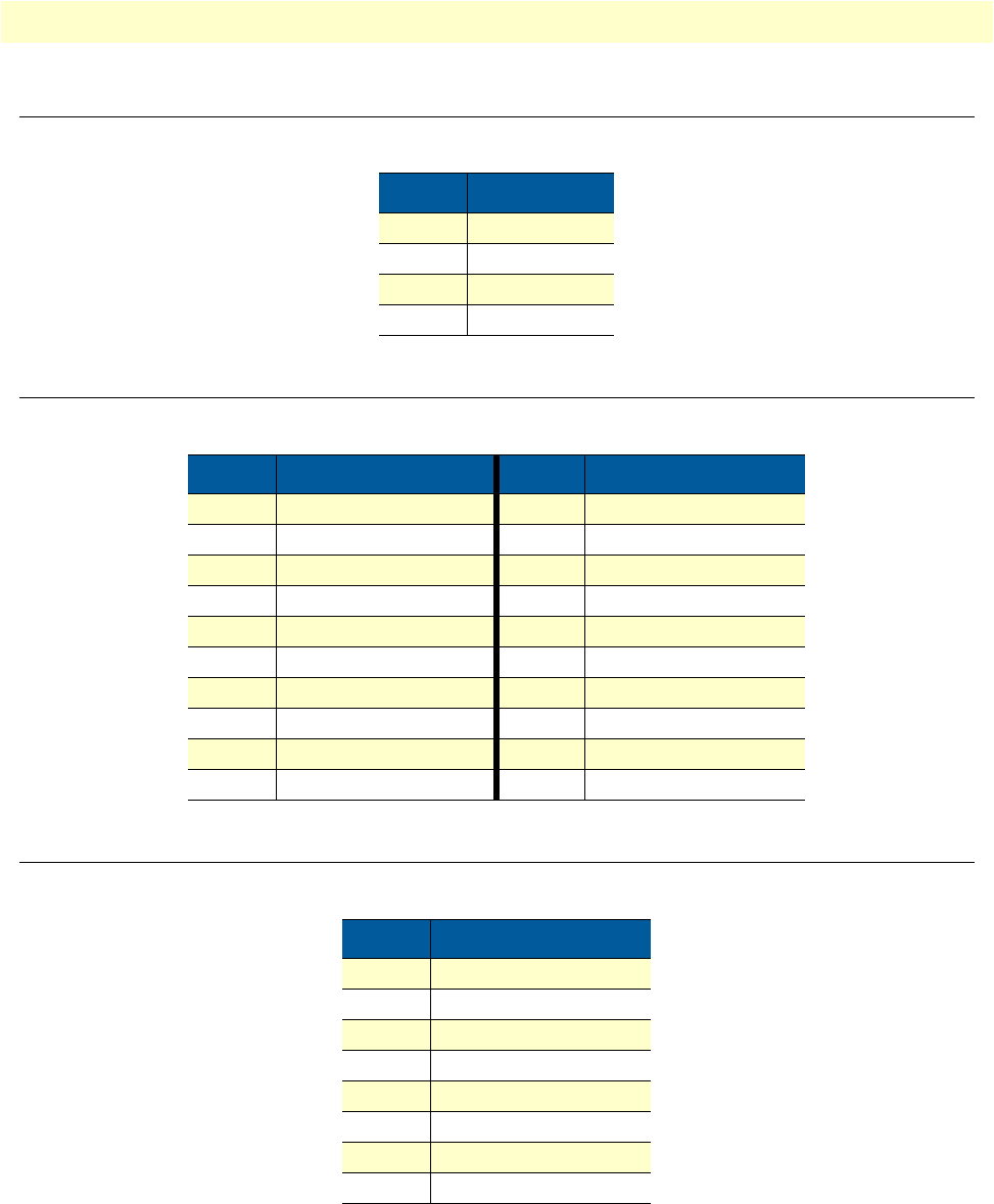
RJ-11 non-shielded DSL port 81
Model 3088 Series User Manual E • Interface pinouts
RJ-11 non-shielded DSL port
Single twisted-pair (TP) for full-duplex transmission. The signals are polarity insensitive.
V. 3 5 i n t e r fa c e
DB-25 female connector (DCE orientation)
T1/E1 interface
RJ-48C female connector
Pin # Signal
1
2Tip
3Ring
4
Pin # Signal Pin # Signal
1Frame Ground 12 TxC-b
2TxD-a 14 TxD-b
3RxD-a 15 TxC-a
4RTS 16 RxD-b
5CTS 17 RxC-a
6DSR 18 LL
7Signal Ground 20 DTR
8CD 21 RL
9RxC-b 24 ExtC-a
11 ExtC-b 25 TM
Pin # Signal
1Receive (Ring)
2Receive (Tip)
3Shield
4Transmit (Ring)
5Transmit (Tip)
6Shield
7No connection
8No connection
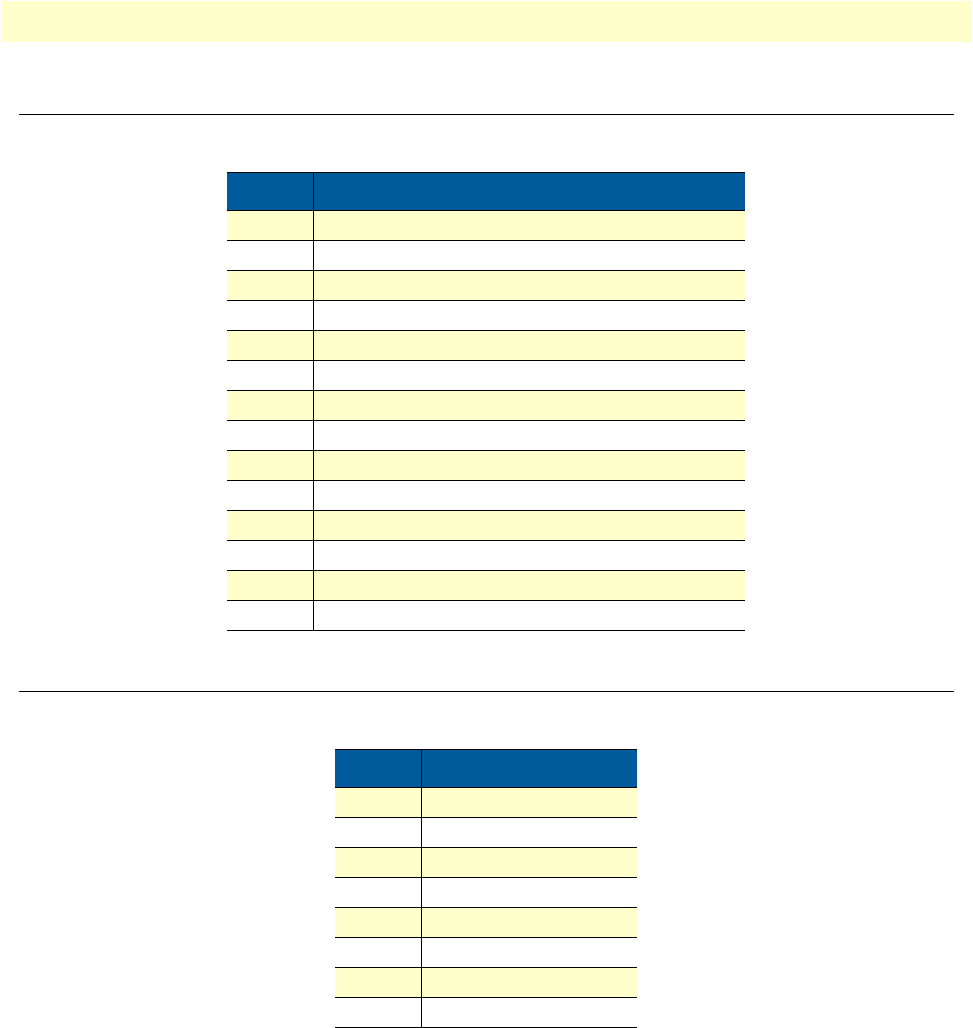
X.21 interface 82
Model 3088 Series User Manual E • Interface pinouts
X.21 interface
D-sub-15 female connector (DTE/DCE orientation).
RS-232 console interface pin assignments
RJ-45 non-shielded connector (EIA-561)
Pin # Signal
1Frame Ground
2T - Transmit Data-A (DTE Source)
3C - Control-A (DTE Source)
4R - Receive Data-A (DCE Source)
5I - Indication-A (DCE Source)
6S - Signal Element Timing-A (DCE Source)
7BT - Byte Timing-A (DCE Source)
8SGND - Signal Ground
9T/ - Transmit Data-B (DTE Source)
10 C/ - Control-B (DTE Source)
11 R/ - Receive Data-B (DCE Source)
12 I/ Indication-B (DCE Source)
13 S/ Signal Element Timing-B (DCE Source)
14 BT/ - Byte Timing-B (DCE Source)
Pin # Signal
1DSR (out)
2CD (out)
3DTR (in)
4Signal Ground
5RD (out)
6TD (in)
7CTS (out)
8RTS (in)
