Patton Electronic Onsite 2800 Users Manual IPLink Series Getting Started Guide
ONSITE 2800 2800
2800 to the manual ceed8fd4-29fe-4714-9583-414b0745a92e
2015-02-06
: Patton-Electronic Patton-Electronic-Onsite-2800-Users-Manual-517244 patton-electronic-onsite-2800-users-manual-517244 patton-electronic pdf
Open the PDF directly: View PDF ![]() .
.
Page Count: 135 [warning: Documents this large are best viewed by clicking the View PDF Link!]
- Summary Table of Contents
- Table of Contents
- List of Figures
- List of Tables
- About this guide
- Chapter 1 General information
- Chapter 2 Hardware installation
- Chapter 3 Getting started with the OnSite Managed VPN Router
- Chapter 4 Serial port configuration
- Introduction
- Serial port configuration task list
- Disabling an interface
- Enabling an interface
- Configuring the encapsulation for Frame Relay
- Enter Frame Relay mode
- Configuring the LMI type
- Configuring the keep-alive interval
- Entering Frame Relay PVC configuration mode
- Configuring the PVC encapsulation type
- Binding the Frame Relay PVC to IP interface
- Enabling a Frame Relay PVC
- Disabling a Frame Relay PVC
- Displaying serial port information
- Displaying Frame Relay information
- Integrated service access
- Chapter 5 T1/E1 port configuration
- Introduction
- T1/E1 port configuration task list
- Enable/Disable T1/E1 port
- Configuring T1/E1 port-type
- Configuring T1/E1 clock-mode
- Configuring T1/E1 line-code
- Configuring T1/E1 framing
- Configuring T1/E1 line-build-out (T1 only)
- Configuring T1/E1 used-connector (E1 only)
- Configuring T1/E1 application mode
- Configuring T1/E1 LOS threshold
- Configuring T1/E1 encapsulation
- Create a Channel-Group
- Configuring Channel-Group Timeslots
- Configuring Channel-Group Encapsulation
- Entering HDLC Configuration Mode
- Configuring HDLC CRC-Type
- Configuring HDLC Encapsulation
- T1/E1 Configuration Examples
- Chapter 6 VPN configuration
- Chapter 7 Access control list configuration
- Introduction
- About access control lists
- Access control list configuration task list
- Mapping out the goals of the access control list
- Creating an access control list profile and enter configuration mode
- Adding a filter rule to the current access control list profile
- Adding an ICMP filter rule to the current access control list profile
- Adding a TCP, UDP or SCTP filter rule to the current access control list profile
- Binding and unbinding an access control list profile to an IP interface
- Displaying an access control list profile
- Debugging an access control list profile
- Examples
- Chapter 8 Link scheduler configuration
- Introduction
- Configuring access control lists
- Configuring quality of service (QoS)
- Quick references
- Link scheduler configuration task list
- Defining the access control list profile
- Creating a service policy profile
- Specifying the handling of traffic-classes
- Defining fair queuing weight
- Defining the bit-rate
- Defining absolute priority
- Defining the maximum queue length
- Specifying the type-of-service (TOS) field
- Specifying the precedence field
- Specifying differentiated services codepoint (DSCP) marking
- Specifying layer 2 marking
- Defining random early detection
- Discarding Excess Load
- Devoting the service policy profile to an interface
- Displaying link arbitration status
- Displaying link scheduling profile information
- Enable statistics gathering
- Chapter 9 LEDs status and monitoring
- Chapter 10 Contacting Patton for assistance
- Appendix A Compliance information
- Appendix B Specifications
- Appendix C Cabling
- Appendix D Port pin-outs
- Appendix E OnSite 2800 Series factory configuration
- Appendix F Installation checklist
OnSite 2800 Series
Managed VPN Router
User Manual
Sales Office: +1 (301) 975-1000
Technical Support: +1 (301) 975-1007
E-mail: support@patton.com
WWW: www.patton.com
Part Number: 07M2800-GS, Rev. F
Revised: February 22, 2012
Important
This is a Class A device and is intended for use in a light industrial environment. It is not intended nor approved for use in an industrial
or residential environment.
Patton Electronics Company, Inc.
7622 Rickenbacker Drive
Gaithersburg, MD 20879 USA
Tel: +1 (301) 975-1000
Fax: +1 (301) 869-9293
Support: +1 (301) 975-1007
URL: www.patton.com
E-Mail: support@patton.com
Trademark Statement
The term OnSite is a trademark of Patton Electronics Company. All other trademarks
presented in this document are the property of their respective owners.
Copyright © 2012, Patton Electronics Company. All rights reserved.
The information in this document is subject to change without notice. Patton Elec-
tronics assumes no liability for errors that may appear in this document.
Warranty Information
The software described in this document is furnished under a license and may be used
or copied only in accordance with the terms of such license.
Patton Electronics warrants all OnSite router components to be free from defects,
and will—at our option—repair or replace the product should it fail within one year
from the first date of the shipment.
This warranty is limited to defects in workmanship or materials, and does not cover
customer damage, abuse or unauthorized modification. If the product fails to perform
as warranted, your sole recourse shall be repair or replacement as described above.
Under no condition shall Patton Electronics be liable for any damages incurred by
the use of this product. These damages include, but are not limited to, the following:
lost profits, lost savings and incidental or consequential damages arising from the use
of or inability to use this product. Patton Electronics specifically disclaims all other
warranties, expressed or implied, and the installation or use of this product shall be
deemed an acceptance of these terms by the user.

3
Summary Table of Contents
1General information...................................................................................................................................... 17
2Hardware installation.................................................................................................................................... 26
3Getting started with the OnSite Managed VPN Router ................................................................................ 38
4Serial port configuration ............................................................................................................................... 44
5T1/E1 port configuration .............................................................................................................................. 58
6VPN configuration ........................................................................................................................................ 67
7Access control list configuration.................................................................................................................... 79
8Link scheduler configuration ........................................................................................................................ 93
9LEDs status and monitoring ....................................................................................................................... 112
10 Contacting Patton for assistance ................................................................................................................. 114
ACompliance information ............................................................................................................................ 117
BSpecifications .............................................................................................................................................. 120
CCabling ....................................................................................................................................................... 124
DPort pin-outs .............................................................................................................................................. 128
EOnSite 2800 Series factory configuration ................................................................................................... 132
FInstallation checklist .................................................................................................................................. 134

4
Table of Contents
Summary Table of Contents ........................................................................................................................... 3
Table of Contents ........................................................................................................................................... 4
List of Figures ............................................................................................................................................... 10
List of Tables ................................................................................................................................................ 11
About this guide ........................................................................................................................................... 12
Audience............................................................................................................................................................... 12
Structure............................................................................................................................................................... 12
Precautions ........................................................................................................................................................... 13
Safety when working with electricity ...............................................................................................................14
General observations .......................................................................................................................................15
Typographical conventions used in this document................................................................................................ 16
General conventions .......................................................................................................................................16
1General information...................................................................................................................................... 17
OnSite Model 2800 Series overview ......................................................................................................................18
OnSite 2800 Series detailed description ..........................................................................................................19
OnSite 2800 Series model codes ................................................................................................................19
Serial WAN models ............................................................................................................................19
Ethernet WAN models .......................................................................................................................20
Model code extensions ..............................................................................................................................21
Ports descriptions ......................................................................................................................................22
Applications overview............................................................................................................................................23
Branch-Office virtual private network over Frame Relay service ......................................................................23
Corporate multi-function virtual private network ...........................................................................................24
2Hardware installation.................................................................................................................................... 26
Planning the installation........................................................................................................................................27
Installation checklist .......................................................................................................................................28
Site log ............................................................................................................................................................29
Network information ......................................................................................................................................29
Network Diagram .....................................................................................................................................29
IP related information .....................................................................................................................................29
Software tools .................................................................................................................................................29
Power source ...................................................................................................................................................29
Location and mounting requirements .............................................................................................................30
Installing the VPN router......................................................................................................................................30
Mounting the VPN router ..............................................................................................................................30
Connecting cables ...........................................................................................................................................30
Installing the Ethernet cable ......................................................................................................................30
Installing the serial WAN cable .................................................................................................................31
Installing the V.35 interface cable .......................................................................................................32
Installing the X.21 interface cable .......................................................................................................33

5
OnSite 2800 Series User Manual Table of Contents
Installing the T1/E1 twisted pair cables ..............................................................................................34
Installing the E1 dual coaxial cables ....................................................................................................35
Connecting to external power source .........................................................................................................36
3Getting started with the OnSite Managed VPN Router ................................................................................ 38
Introduction..........................................................................................................................................................39
1. Configure IP address .........................................................................................................................................40
Power connection and default configuration ...................................................................................................40
Connect with the serial interface .....................................................................................................................40
Login ..............................................................................................................................................................41
Changing the IP address .................................................................................................................................41
2. Connect the OnSite VPN Router to the network..............................................................................................42
3. Load configuration ............................................................................................................................................42
4Serial port configuration ............................................................................................................................... 44
Introduction..........................................................................................................................................................45
Serial port configuration task list ...........................................................................................................................45
Disabling an interface .....................................................................................................................................45
Enabling an interface ......................................................................................................................................46
Configuring the encapsulation for Frame Relay ..............................................................................................47
Enter Frame Relay mode .................................................................................................................................48
Configuring the LMI type ...............................................................................................................................48
Configuring the keep-alive interval .................................................................................................................49
Entering Frame Relay PVC configuration mode .............................................................................................49
Configuring the PVC encapsulation type ........................................................................................................50
Binding the Frame Relay PVC to IP interface .................................................................................................50
Enabling a Frame Relay PVC ..........................................................................................................................52
Disabling a Frame Relay PVC .........................................................................................................................52
Displaying serial port information ...................................................................................................................53
Displaying Frame Relay information ...............................................................................................................54
Integrated service access ..................................................................................................................................55
5T1/E1 port configuration .............................................................................................................................. 58
Introduction..........................................................................................................................................................59
T1/E1 port configuration task list..........................................................................................................................59
Enable/Disable T1/E1 port .............................................................................................................................59
Configuring T1/E1 port-type ..........................................................................................................................60
Configuring T1/E1 clock-mode ......................................................................................................................60
Configuring T1/E1 line-code ..........................................................................................................................60
Configuring T1/E1 framing ............................................................................................................................61
Configuring T1/E1 line-build-out (T1 only) ..................................................................................................61
Configuring T1/E1 used-connector (E1 only) .................................................................................................61
Configuring T1/E1 application mode .............................................................................................................62
Configuring T1/E1 LOS threshold .................................................................................................................62
Configuring T1/E1 encapsulation ...................................................................................................................62
Create a Channel-Group .................................................................................................................................62

6
OnSite 2800 Series User Manual Table of Contents
Configuring Channel-Group Timeslots ..........................................................................................................63
Configuring Channel-Group Encapsulation ...................................................................................................63
Entering HDLC Configuration Mode ............................................................................................................63
Configuring HDLC CRC-Type .....................................................................................................................64
Configuring HDLC Encapsulation .................................................................................................................64
T1/E1 Configuration Examples ......................................................................................................................64
Example 1: Frame Relay without a channel-group ....................................................................................65
Example 2: Framerelay with a channel-group ............................................................................................66
Example 3: PPP without a channel-group .................................................................................................66
Example 4: PPP with a channel-group ......................................................................................................66
6VPN configuration ........................................................................................................................................ 67
Introduction..........................................................................................................................................................68
Authentication ................................................................................................................................................68
Encryption ......................................................................................................................................................68
Transport and tunnel modes ...........................................................................................................................69
VPN configuration task list ...................................................................................................................................69
Creating an IPsec transformation profile .........................................................................................................69
Creating an IPsec policy profile .......................................................................................................................70
Creating/modifying an outgoing ACL profile for IPsec ...................................................................................72
Configuration of an IP interface and the IP router for IPsec ............................................................................73
Displaying IPsec configuration information ....................................................................................................73
Debugging IPsec .............................................................................................................................................74
Sample configurations ...........................................................................................................................................75
IPsec tunnel, DES encryption .........................................................................................................................75
OnSite configuration .................................................................................................................................75
Cisco router configuration ........................................................................................................................76
IPsec tunnel, AES encryption at 256 bit key length, AH authentication with HMAC-SHA1-96 ....................76
OnSite configuration .................................................................................................................................76
Cisco router configuration ........................................................................................................................77
IPsec tunnel, 3DES encryption at 192 bit key length, ESP authentication with HMAC-MD5-96 ..................77
OnSite configuration .................................................................................................................................77
Cisco router configuration ........................................................................................................................77
7Access control list configuration.................................................................................................................... 79
Introduction..........................................................................................................................................................80
About access control lists .......................................................................................................................................80
What access lists do .........................................................................................................................................80
Why you should configure access lists .............................................................................................................80
When to configure access lists .........................................................................................................................81
Features of access control lists .........................................................................................................................81
Access control list configuration task list................................................................................................................82
Mapping out the goals of the access control list ...............................................................................................82
Creating an access control list profile and enter configuration mode ...............................................................83
Adding a filter rule to the current access control list profile .............................................................................83

7
OnSite 2800 Series User Manual Table of Contents
Adding an ICMP filter rule to the current access control list profile ................................................................85
Adding a TCP, UDP or SCTP filter rule to the current access control list profile ...........................................87
Binding and unbinding an access control list profile to an IP interface ............................................................89
Displaying an access control list profile ...........................................................................................................90
Debugging an access control list profile ...........................................................................................................90
Examples ...............................................................................................................................................................92
Denying a specific subnet ................................................................................................................................92
8Link scheduler configuration ........................................................................................................................ 93
Introduction..........................................................................................................................................................94
Configuring access control lists..............................................................................................................................94
Configuring quality of service (QoS) .....................................................................................................................95
Applying scheduling at the bottleneck .............................................................................................................95
Using traffic classes .........................................................................................................................................95
Introduction to Scheduling .............................................................................................................................96
Priority ......................................................................................................................................................96
Weighted fair queuing (WFQ) ..................................................................................................................96
Shaping .....................................................................................................................................................97
Burst tolerant shaping or wfq ....................................................................................................................97
Hierarchy ..................................................................................................................................................97
Quick references....................................................................................................................................................98
Setting the modem rate ...................................................................................................................................98
Command cross reference ...............................................................................................................................99
Link scheduler configuration task list.....................................................................................................................99
Defining the access control list profile ...........................................................................................................100
Packet classification .................................................................................................................................100
Creating an access control list ..................................................................................................................101
Creating a service policy profile .....................................................................................................................102
Specifying the handling of traffic-classes ........................................................................................................104
Defining fair queuing weight ...................................................................................................................104
Defining the bit-rate ...............................................................................................................................105
Defining absolute priority .......................................................................................................................105
Defining the maximum queue length ......................................................................................................105
Specifying the type-of-service (TOS) field ...............................................................................................105
Specifying the precedence field ................................................................................................................106
Specifying differentiated services codepoint (DSCP) marking .................................................................106
Specifying layer 2 marking ......................................................................................................................107
Defining random early detection .............................................................................................................108
Discarding Excess Load ...........................................................................................................................108
Devoting the service policy profile to an interface .........................................................................................109
Displaying link arbitration status ..................................................................................................................110
Displaying link scheduling profile information .............................................................................................110
Enable statistics gathering .............................................................................................................................110
9LEDs status and monitoring ....................................................................................................................... 112

8
OnSite 2800 Series User Manual Table of Contents
Status LEDs.........................................................................................................................................................113
10 Contacting Patton for assistance ................................................................................................................. 114
Introduction........................................................................................................................................................115
Contact information............................................................................................................................................115
Patton Support Headquarters in the USA .....................................................................................................115
Alternate Patton support for Europe, Middle Ease, and Africa (EMEA) ........................................................115
Warranty Service and Returned Merchandise Authorizations (RMAs).................................................................115
Warranty coverage ........................................................................................................................................115
Out-of-warranty service ...........................................................................................................................116
Returns for credit ....................................................................................................................................116
Return for credit policy ...........................................................................................................................116
RMA numbers ..............................................................................................................................................116
Shipping instructions ..............................................................................................................................116
ACompliance information ............................................................................................................................ 117
Compliance .........................................................................................................................................................118
EMC .............................................................................................................................................................118
Safety ............................................................................................................................................................118
PSTN Regulatory ..........................................................................................................................................118
Radio and TV Interference (FCC Part 15) ..........................................................................................................118
CE Declaration of Conformity ............................................................................................................................118
Authorized European Representative ...................................................................................................................119
FCC Part 68 (ACTA) Statement (Model 2803 only)...........................................................................................119
Industry Canada Notice (Model 2803 only)........................................................................................................119
BSpecifications .............................................................................................................................................. 120
Ethernet interfaces...............................................................................................................................................121
Sync serial interface .............................................................................................................................................121
T1/E1 interface (Model 2803 only).....................................................................................................................121
PPP support ........................................................................................................................................................121
IP services............................................................................................................................................................122
Management .......................................................................................................................................................122
Operating environment .......................................................................................................................................122
Operating temperature ..................................................................................................................................122
Operating humidity ......................................................................................................................................122
System.................................................................................................................................................................122
Dimensions .........................................................................................................................................................122
Power supply .......................................................................................................................................................123
Internal AC version .......................................................................................................................................123
12VDC version with External AC Power Adapter
(Models 2802, 2821, 2835) ..........................................................................................................................123
5VDC Version with External Power Adapter (Model 2805) .........................................................................123
CCabling ....................................................................................................................................................... 124
Introduction........................................................................................................................................................125
Serial console.......................................................................................................................................................125

9
OnSite 2800 Series User Manual Table of Contents
Ethernet 10Base-T and 100Base-T......................................................................................................................126
DPort pin-outs .............................................................................................................................................. 128
Introduction........................................................................................................................................................129
Console port, RJ-45, EIA-561 (RS-232)..............................................................................................................129
Ethernet 10Base-T and 100Base-T port ..............................................................................................................130
Sync serial port....................................................................................................................................................130
V.35 serial port .............................................................................................................................................130
X.21 serial port .............................................................................................................................................131
EOnSite 2800 Series factory configuration ................................................................................................... 132
Introduction........................................................................................................................................................133
FInstallation checklist .................................................................................................................................. 134
Introduction........................................................................................................................................................135

10
List of Figures
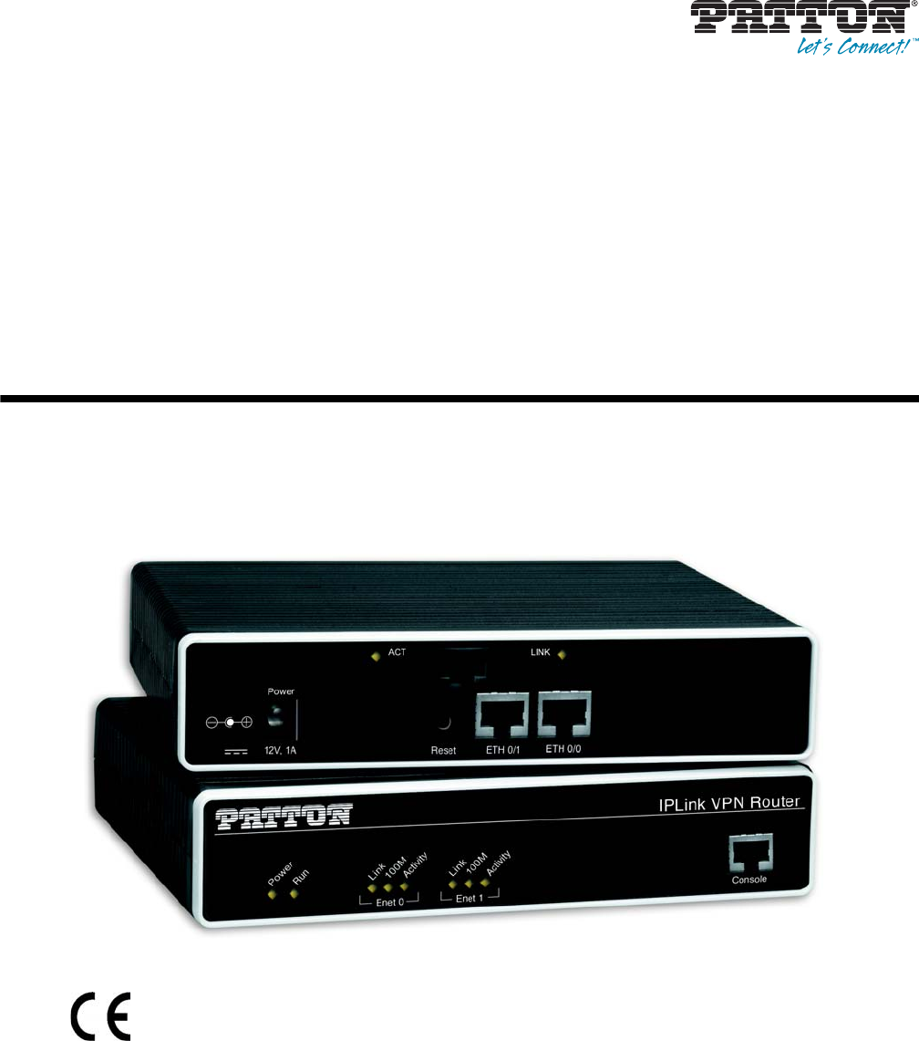
1 OnSite Managed VPN Router (2805 shown) . . . . . . . . . . . . . . . . . . . . . . . . . . . . . . . . . . . . . . . . . . . . . . . . . . 18
2 OnSite 2800 Series X.21, and V.35 connectors . . . . . . . . . . . . . . . . . . . . . . . . . . . . . . . . . . . . . . . . . . . . . . . . 19
3 OnSite 2800 Series 10Base-T Ethernet port connectors . . . . . . . . . . . . . . . . . . . . . . . . . . . . . . . . . . . . . . . . . . 20
4 OnSite 2800 Series power input connectors . . . . . . . . . . . . . . . . . . . . . . . . . . . . . . . . . . . . . . . . . . . . . . . . . . . 21
5 OnSite 2800 Series front panels . . . . . . . . . . . . . . . . . . . . . . . . . . . . . . . . . . . . . . . . . . . . . . . . . . . . . . . . . . . . 22
6 Branch-office virtual private network over a Frame-Relay service network . . . . . . . . . . . . . . . . . . . . . . . . . . . . 23
7 Corporate multi-function virtual private network . . . . . . . . . . . . . . . . . . . . . . . . . . . . . . . . . . . . . . . . . . . . . . . 24
8 Connecting an OnSite 2800 Series device to a hub . . . . . . . . . . . . . . . . . . . . . . . . . . . . . . . . . . . . . . . . . . . . . . 31
9 Rear view of the router showing location of V.35 interface connector . . . . . . . . . . . . . . . . . . . . . . . . . . . . . . . . 32
10 Rear view of the router showing location of X.21 interface connector . . . . . . . . . . . . . . . . . . . . . . . . . . . . . . . . 33
11 Rear panel of 2803K/EUI . . . . . . . . . . . . . . . . . . . . . . . . . . . . . . . . . . . . . . . . . . . . . . . . . . . . . . . . . . . . . . . . . 34
12 Rear panel of 2803T/EUI . . . . . . . . . . . . . . . . . . . . . . . . . . . . . . . . . . . . . . . . . . . . . . . . . . . . . . . . . . . . . . . . . 34
13 Rear panel of 2803K/UI . . . . . . . . . . . . . . . . . . . . . . . . . . . . . . . . . . . . . . . . . . . . . . . . . . . . . . . . . . . . . . . . . . 35
14 Power connector location on rear panel . . . . . . . . . . . . . . . . . . . . . . . . . . . . . . . . . . . . . . . . . . . . . . . . . . . . . . 36
15 VPN Router front panel LEDs and Console port locations (OnSite 2835 shown) . . . . . . . . . . . . . . . . . . . . . . 37
16 Steps for setting up a new OnSite VPN Router . . . . . . . . . . . . . . . . . . . . . . . . . . . . . . . . . . . . . . . . . . . . . . . . 39
17 Connecting to the terminal . . . . . . . . . . . . . . . . . . . . . . . . . . . . . . . . . . . . . . . . . . . . . . . . . . . . . . . . . . . . . . . . 40
18 Connecting the OnSite VPN Router to the network . . . . . . . . . . . . . . . . . . . . . . . . . . . . . . . . . . . . . . . . . . . . 42
19 IP interface wan is bound to PVC 1 on port serial 0 0 . . . . . . . . . . . . . . . . . . . . . . . . . . . . . . . . . . . . . . . . . . . 51
20 Typical Integrated Service Access Scenario with dedicated PVCs . . . . . . . . . . . . . . . . . . . . . . . . . . . . . . . . . . . 55
21 IP Context with logical IP interfaces bound to Ethernet port, serial port PVC 1 and PVC 2 . . . . . . . . . . . . . . 56
22 Using traffic filters to prevent traffic from being routed to a network . . . . . . . . . . . . . . . . . . . . . . . . . . . . . . . . 81
23 Deny a specific subnet on an interface . . . . . . . . . . . . . . . . . . . . . . . . . . . . . . . . . . . . . . . . . . . . . . . . . . . . . . . 92
24 IP context and related elements . . . . . . . . . . . . . . . . . . . . . . . . . . . . . . . . . . . . . . . . . . . . . . . . . . . . . . . . . . . . 95
25 Packet routing in OnSite . . . . . . . . . . . . . . . . . . . . . . . . . . . . . . . . . . . . . . . . . . . . . . . . . . . . . . . . . . . . . . . . . 96
26 Example of Hierarchical Scheduling . . . . . . . . . . . . . . . . . . . . . . . . . . . . . . . . . . . . . . . . . . . . . . . . . . . . . . . . . 98
27 Elements of link scheduler configuration . . . . . . . . . . . . . . . . . . . . . . . . . . . . . . . . . . . . . . . . . . . . . . . . . . . . 100
28 Scenario with Web server regarded as a single source host . . . . . . . . . . . . . . . . . . . . . . . . . . . . . . . . . . . . . . . . 101
29 Structure of a Service-Policy Profile . . . . . . . . . . . . . . . . . . . . . . . . . . . . . . . . . . . . . . . . . . . . . . . . . . . . . . . . 103
30 Using a Service Policy Profile on an IP Interface . . . . . . . . . . . . . . . . . . . . . . . . . . . . . . . . . . . . . . . . . . . . . . . 109
31 Examples of OnSite 2800 Series front panels . . . . . . . . . . . . . . . . . . . . . . . . . . . . . . . . . . . . . . . . . . . . . . . . . 113
32 Connecting a serial terminal . . . . . . . . . . . . . . . . . . . . . . . . . . . . . . . . . . . . . . . . . . . . . . . . . . . . . . . . . . . . . . 125
33 Ethernet cross-over . . . . . . . . . . . . . . . . . . . . . . . . . . . . . . . . . . . . . . . . . . . . . . . . . . . . . . . . . . . . . . . . . . . . . 126
34 Ethernet straight-through . . . . . . . . . . . . . . . . . . . . . . . . . . . . . . . . . . . . . . . . . . . . . . . . . . . . . . . . . . . . . . . . 127
35 EIA-561 (RJ-45 8-pin) port . . . . . . . . . . . . . . . . . . . . . . . . . . . . . . . . . . . . . . . . . . . . . . . . . . . . . . . . . . . . . . 129

11
List of Tables
1 General conventions . . . . . . . . . . . . . . . . . . . . . . . . . . . . . . . . . . . . . . . . . . . . . . . . . . . . . . . . . . . . . . . . . . . . . 16
2 Rear panel ports . . . . . . . . . . . . . . . . . . . . . . . . . . . . . . . . . . . . . . . . . . . . . . . . . . . . . . . . . . . . . . . . . . . . . . . . 22
3 Installation checklist . . . . . . . . . . . . . . . . . . . . . . . . . . . . . . . . . . . . . . . . . . . . . . . . . . . . . . . . . . . . . . . . . . . . . 28
4 Sample site log entries . . . . . . . . . . . . . . . . . . . . . . . . . . . . . . . . . . . . . . . . . . . . . . . . . . . . . . . . . . . . . . . . . . . . 29
5 Ethernet 10/100Base-T (RJ-45) port pin-outs . . . . . . . . . . . . . . . . . . . . . . . . . . . . . . . . . . . . . . . . . . . . . . . . . 31
6 Signal pin-outs for the V.35 interface on the OnSite 2800 . . . . . . . . . . . . . . . . . . . . . . . . . . . . . . . . . . . . . . . . 32
7 Signal pin-outs for the X.21 interface on the OnSite 2800 . . . . . . . . . . . . . . . . . . . . . . . . . . . . . . . . . . . . . . . . 34
8 RJ-48C receptacle . . . . . . . . . . . . . . . . . . . . . . . . . . . . . . . . . . . . . . . . . . . . . . . . . . . . . . . . . . . . . . . . . . . . . . . 34
9 Factory default IP address and network mask configuration . . . . . . . . . . . . . . . . . . . . . . . . . . . . . . . . . . . . . . . 40
10 Command cross reference . . . . . . . . . . . . . . . . . . . . . . . . . . . . . . . . . . . . . . . . . . . . . . . . . . . . . . . . . . . . . . . . . 99
11 TOS values and their meaning . . . . . . . . . . . . . . . . . . . . . . . . . . . . . . . . . . . . . . . . . . . . . . . . . . . . . . . . . . . . 106
12 Traffic control info (TCI) field . . . . . . . . . . . . . . . . . . . . . . . . . . . . . . . . . . . . . . . . . . . . . . . . . . . . . . . . . . . . 107
13 Values defining detail of the queuing statistics . . . . . . . . . . . . . . . . . . . . . . . . . . . . . . . . . . . . . . . . . . . . . . . . 111
14 OnSite LED Indications . . . . . . . . . . . . . . . . . . . . . . . . . . . . . . . . . . . . . . . . . . . . . . . . . . . . . . . . . . . . . . . . . 113
15 RS-232 Console Port . . . . . . . . . . . . . . . . . . . . . . . . . . . . . . . . . . . . . . . . . . . . . . . . . . . . . . . . . . . . . . . . . . . 129
16 RJ-45 socket . . . . . . . . . . . . . . . . . . . . . . . . . . . . . . . . . . . . . . . . . . . . . . . . . . . . . . . . . . . . . . . . . . . . . . . . . . 130
17 V.35 Female DB-25 connector . . . . . . . . . . . . . . . . . . . . . . . . . . . . . . . . . . . . . . . . . . . . . . . . . . . . . . . . . . . . 130
18 X.21 Female DB-15 connector . . . . . . . . . . . . . . . . . . . . . . . . . . . . . . . . . . . . . . . . . . . . . . . . . . . . . . . . . . . . 131
19 Installation checklist . . . . . . . . . . . . . . . . . . . . . . . . . . . . . . . . . . . . . . . . . . . . . . . . . . . . . . . . . . . . . . . . . . . . 135

12
About this guide
This guide describes OnSite VPN router hardware, installation, and configuration.
Audience
This guide is intended for the following users:
•Operators
•Installers
•Maintenance technicians
Structure
This guide contains the following chapters and appendices:
•Chapter 1 on page 17 provides information about router features, capabilities, operation, and applications
•Chapter 2 on page 26 provides hardware installation procedures
•Chapter 3 on page 38 provides quick-start procedures for configuring the OnSite VPN router
•Chapter 4 on page 44 provides an overview of the serial port and describes the tasks involved in its configu-
ration through the OnSite router.
•Chapter 5 on page 58 provides information on T1/E1 port configuration.
•Chapter 6 on page 67 describes how to configure the VPN connections between two OnSite routers or
between an OnSite and a third-party device.
•Chapter 7 on page 79 provides an overview of IP access control lists and describes the tasks involved in their
configuration through the OnSite router.
•Chapter 8 on page 93 describes how to use and configure OnSite quality of service (QoS) features.
•Chapter 9 on page 112 provides LED definitions
•Chapter 10 on page 114 contains information on contacting Patton technical support for assistance
•Appendix A on page 117 contains compliance information
•Appendix B on page 120 contains specifications for the routers
•Appendix C on page 124 provides cable recommendations
•Appendix D on page 128 describes the router’s ports and pin-outs
•Appendix E on page 132 lists the factory configuration settings for the OnSite VPN router
•Appendix F on page 134 provides license information that describes acceptable usage of the software pro-
vided with the OnSite VPN router
For best results, read the contents of this guide before you install the router.

13
OnSite 2800 Series User Manual About this guide
Precautions
Notes, cautions, and warnings, which have the following meanings, are used throughout this guide to help you
become aware of potential problems. Warnings are intended to prevent safety hazards that could result in per-
sonal injury. Cautions are intended to prevent situations that could result in property damage or
impaired functioning.
Note
A note presents additional information or interesting sidelights.
The alert symbol and IMPORTANT heading calls attention to
important information.
The alert symbol and CAUTION heading indicate a potential
hazard. Strictly follow the instructions to avoid
property damage.
The shock hazard symbol and CAUTION heading indicate a
potential electric shock hazard. Strictly follow the instructions to
avoid property damage caused by electric shock.
The alert symbol and WARNING heading indicate a potential safety hazard.
Strictly follow the warning instructions to avoid personal injury.
The shock hazard symbol and WARNING heading indicate a potential electric
shock hazard. Strictly follow the warning instructions to avoid injury caused
by electric shock.
IMPORTANT
CAUTION
CAUTION
WARNING
WARNING

14
OnSite 2800 Series User Manual About this guide
Safety when working with electricity
The OnSite contains no user serviceable parts. The equipment shall be
returned to Patton Electronics for repairs, or repaired by qualified service per-
sonnel. Opening the OnSite case will void the warranty.
Mains Voltage: Do not open the case the when the power cord is attached. For
systems without a power switch, line voltages are present within the power
supply when the power cords are connected. The mains outlet that is utilized
to power the devise shall be within 10 feet (3 meters) of the device, shall be
easily accessible, and protected by a circuit breaker.
For units with an external power adapter, the adapter shall be a listed Lim-
ited Power Source.
For AC powered units, ensure that the power cable used with this device
meets all applicable standards for the country in which it is to be installed,
and that it is connected to a wall outlet which has earth ground.
Hazardous network voltages are present in WAN ports regardless of whether
power to the OnSite is ON or OFF. To avoid electric shock, use caution when
near WAN ports. When detaching cables, detach the end away from the
OnSite first.
Do not work on the system or connect or disconnect cables during periods of
lightning activity.
Before opening the chassis, disconnect the telephone network cables to avoid
contact with telephone line voltages. When detaching the cables, detach the
end away from the OnSite first.
WARNING
WARNING
WARNING
WARNING
WARNING
WARNING
WARNING

15
OnSite 2800 Series User Manual About this guide
General observations
•Clean the case with a soft slightly moist anti-static cloth
•Place the unit on a flat surface and ensure free air circulation
•Avoid exposing the unit to direct sunlight and other heat sources
•Protect the unit from moisture, vapors, and corrosive liquids
The power supply automatically adjusts to accept an input volt-
age from 100 to 240 VAC (50/60 Hz).
Verify that the proper voltage is present before plugging the
power cord into the receptacle. Failure to do so could result in
equipment damage.
The interconnecting cables shall be acceptable for external use
and shall be rated for the proper application with respect to volt-
age, current, anticipated temperature, flammability, and
mechanical serviceability.
In accordance with the requirements of council directive 2002/
96/EC on Waste of Electrical and Electronic Equipment (WEEE),
ensure that at end-of-life you separate this product from other
waste and scrap and deliver to the WEEE collection system in
your country for recycling.
CAUTION
CAUTION

16
OnSite 2800 Series User Manual About this guide
Typographical conventions used in this document
This section describes the typographical conventions and terms used in this guide.
General conventions
The procedures described in this manual use the following text conventions:
Table 1. General conventions
Convention Meaning
Garamond blue type Indicates a cross-reference hyperlink that points to a figure, graphic, table, or sec-
tion heading. Clicking on the hyperlink jumps you to the reference. When you
have finished reviewing the reference, click on the Go to Previous View
button in the Adobe® Acrobat® Reader toolbar to return to your starting point.
Futura bold type Commands and keywords are in boldface font.
Futura bold-italic type Parts of commands, which are related to elements already named by the user, are
in boldface italic font.
Italicized Futura type Variables for which you supply values are in italic font
Futura type
Indicates the names of fields or windows.
Garamond bold type Indicates the names of command buttons that execute an action.
< >
Angle brackets indicate function and keyboard keys, such as <SHIFT>, <CTRL>,
<C>, and so on.
[ ] Elements in square brackets are optional.
{a | b | c} Alternative but required keywords are grouped in braces ({ }) and are separated
by vertical bars ( | )
blue screen Information you enter is in blue screen font.
screen Terminal sessions and information the system displays are in screen font.
node The leading IP address or nodename of an OnSite is substituted with node in
boldface italic font.
2800 The leading 2800 on a command line represents the nodename of the OnSite
#An hash sign at the beginning of a line indicates a comment line.

17
Chapter 1 General information
Chapter contents
OnSite Model 2800 Series overview....................................................................................................................18
OnSite 2800 Series detailed description ........................................................................................................19
OnSite 2800 Series model codes ..............................................................................................................19
Serial WAN models ........................................................................................................................... 19
Ethernet WAN models ....................................................................................................................... 20
Model code extensions .............................................................................................................................21
Ports descriptions .....................................................................................................................................22
Applications overview..........................................................................................................................................23
Branch-Office virtual private network over Frame Relay service .................................................................23
Corporate multi-function virtual private network ..........................................................................................24
OnSite Model 2800 Series overview 18
OnSite 2800 Series User Manual 1 • General information
OnSite Model 2800 Series overview
The OnSite Model 2800 Series Managed VPN Router (see figure 1) delivers secure, optimized communica-
tions across unsecured IP networks between any enterprise headquarters and remote offices, home offices
(RoHo), or mobile users. Patton’s OnSite 2800 family of VPN routers combines an integrated synch-serial
interface for access to the Internet (or any IP network) with full-service IP routing, VPN security via IPSec, and
type-of-service/quality-of-service (ToS/QoS) traffic shaping and prioritization. The built-in V.35 or X.21 serial
interface delivers LAN-to-WAN connectivity without the additional expense of external adapters or
CSU/DSU devices. The Model 2800 Series’ flexible AC or DC power-source options accommodate virtually
any installation environment.
Figure 1. OnSite Managed VPN Router (2805 shown)
Each member of the Model 2800 family provides two 10/100Base-T Ethernet ports and one integrated T1/E1,
V.35, or X.21 synchronous serial WAN port to deliver a managed virtual-private-network (VPN) connection
over the Internet or any unsecured IP network.
OnSite 2800 Series Routers support Frame-Relay and PPP networking with VPN and firewall functionality.
Authentication and firewall services protect against unauthorized users while encryption, and anti-replay capa-
bilities preserve data confidentiality. Patton's powerful CoS and QoS mechanisms provide traffic-shaping and
prioritization to guarantee your mission-critical data is delivered promptly and unimpeded by traffic from
other users on the same LAN. Besides assuring first priority for key information, Patton's advanced QoS tech-
nology enhances the quality and clarity of realtime application such as live voice and video communications
with the main office. These compact VPN Routers support PPP/PPPoE and Frame Relay services over the
serial WAN link.
The OnSite VPN Router performs the following major functions:
•Routed LAN-to-WAN connectivity between two 10/100 Ethernet LAN ports and one V.35, X.21, or syn-
chronous serial WAN port.
•IP Routing with class-of-service/quality-of-service (CoS/QoS) support for Internet or IP-WAN access with
traffic shaping and prioritization.

OnSite Model 2800 Series overview 19
OnSite 2800 Series User Manual 1 • General information
•VPN tunneling for secure traversal of unsecured IP networks
•IPSec payload encryption with authentication header (AH, specified in RFC 2402) and encapsulating secu-
rity payload (ESP, specified in RFC 2406) protects data integrity and confidentiality and prevents unautho-
rized data-replay.
•Firewall capabilities including IP-address and IP-port filtering, access control lists (ACLs), and denial-of-
service (DoS) attack detection.
•Enhanced IP services include domain name service (DNS) resolver and relay, NAT/NAPT, dynamic DNS,
and DHCP server.
OnSite 2800 Series detailed description
The OnSite 2800 Series Managed VPN Router provides secure managed VPN routed networking with 2-port
Ethernet LAN connectivity and serial WAN access via a built-in V.35 or X.21 serial WAN interface
(see figure 2).
Figure 2. OnSite 2800 Series X.21, and V.35 connectors
OnSite 2800 Series model codes
Serial WAN models. The following models come equipped with an integrated V.35 or X.21 serial WAN port
and two 10/100Base-T Ethernet ports (see figure 2):
•OnSite 2821—X.21 WAN interface and two Ethernet ports
•OnSite 2835—V.35 WAN interface and two Ethernet ports
•OnSite 2803—T1/E1 WAN interface and two Ethernet ports
IPLink 2821 X.21 serial WAN port connector
10/100Base-T Ethernet LAN
ports 0/1 and 0/0
IPLink 2835 V.35 serial WAN port connector
10/100Base-T Ethernet LAN
ports 0/1 and 0/0
OnSite Model 2800 Series overview 20
OnSite 2800 Series User Manual 1 • General information
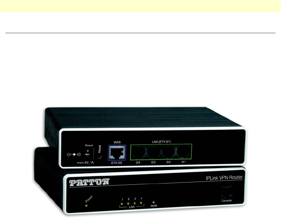
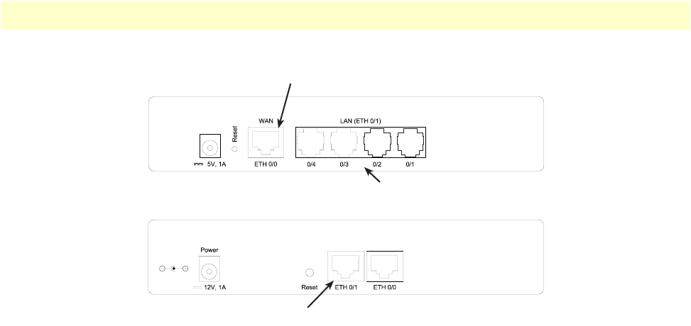
Figure 3. OnSite 2800 Series 10Base-T Ethernet port connectors
Ethernet WAN models. The following models come equipped with 10/100Base-T Ethernet ports only (see
figure 3):
•OnSite 2802—Dual 10/100Base-T Ethernet ports, one for LAN connection and one for connection to
aWAN
•OnSite 2805—Integrated Ethernet switch with four 10/100Base-T Ethernet ports and one 10/100Base-T
Ethernet port for connection to a WAN
•OnSite 2823—Three 10/100 Base-T Ethernet ports with the independent purpose of WAN, LAN, and
DMZ
IPLink 2805 10/100Base-T Ethernet WAN port 0/0
IPLink 2802 10/100Base-T Ethernet ports 0/1 and 0/0
Ethernet LAN ports 0/1 – 0/4
OnSite Model 2800 Series overview 21
OnSite 2800 Series User Manual 1 • General information
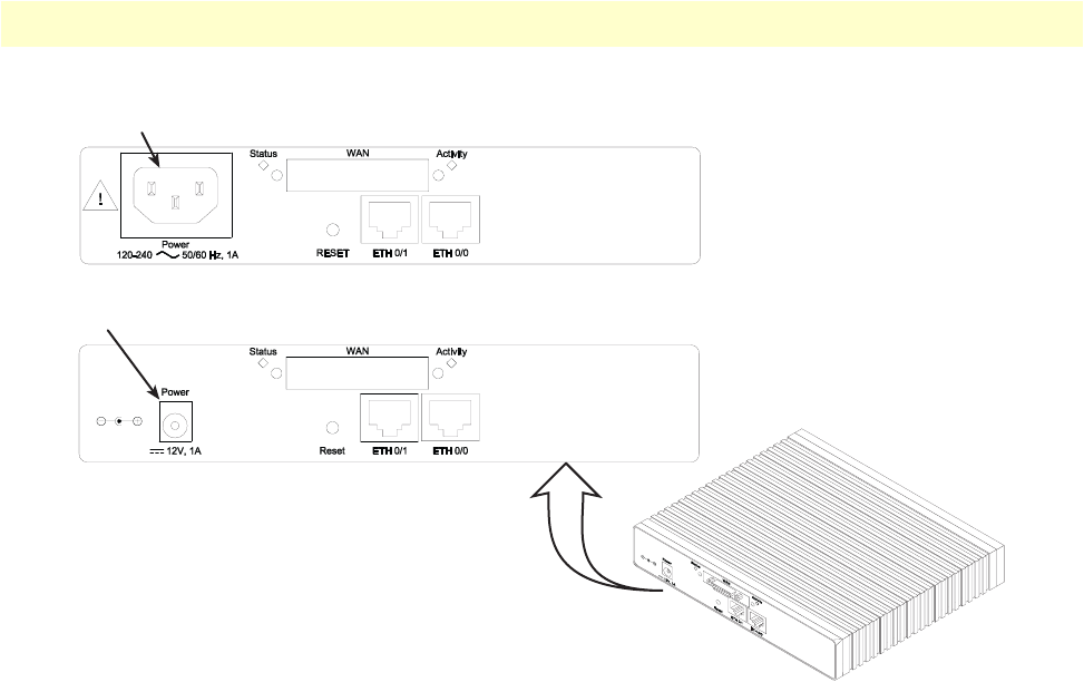
Figure 4. OnSite 2800 Series power input connectors
Model code extensions
A model-code extension indicates the type of power supply the Router model provides. The model-code con-
ventions are:
•UI stands for internal 100–240V AC universal input power supply (see figure 4)
•EUI stands for external 100–240V AC universal input power supply (see figure 4)
For example, the model code 2821/EUI describes an OnSite configured with the following:
•Two 10/100 Base-T Ethernet ports
•X.21 serial WAN data port
•External 120–220 VAC universal input power supply
External power supply connector accepts 12 VDC, 1 A, from external AC adapter (some models accept
+5VDC, see Appendix B, “Specifications” for details)
lnternal power supply connector accepts 100–240 VAC, 50/60 Hz, up to 1 A
OnSite Model 2800 Series overview 22
OnSite 2800 Series User Manual 1 • General information
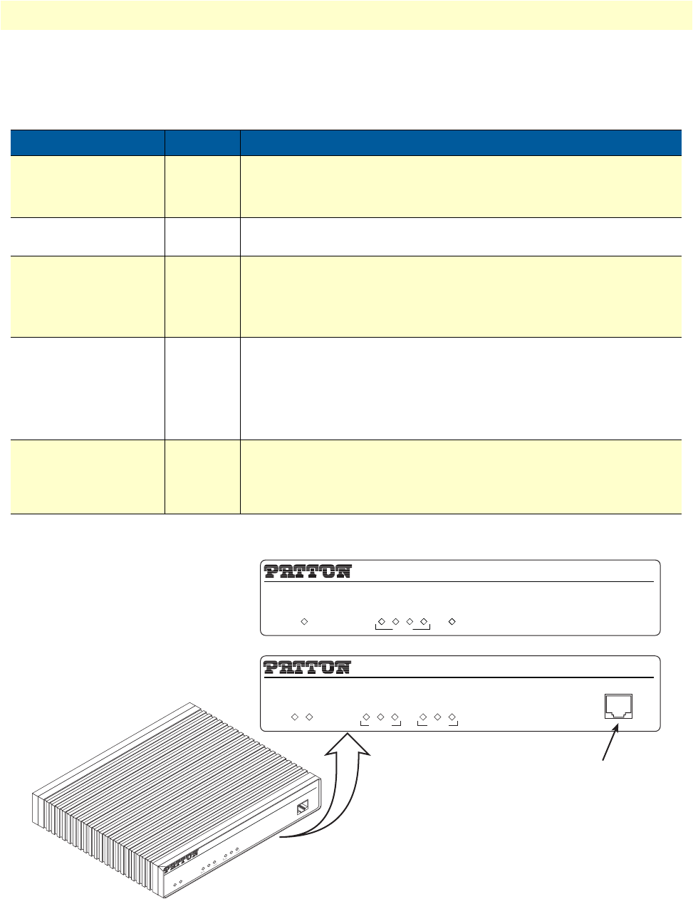
Ports descriptions
The OnSite 2800 Series rear-panel ports are described in table 2.
Figure 5. OnSite 2800 Series front panels
Table 2. Rear panel ports
Port Location Description
10/100 Ethernet
ETH 0/0 (WAN) &
ETH 0/1–0/4 (LAN)
Rear panel RJ-45 connectors (see
figure 2
on page 19 and
figure 3
on page 20)
that connect the router to an Ethernet device (e.g., a cable or DSL
modem, LAN hub or switch).
WAN Rear panel DB-25 or DB-15 receptacle provides a V.35 or X.21 serial interface for
leased-line connection to a WAN at rates up to 2 Mbps.
T1/E1 Rear panel E1
—
G.703/G.704 with HDB3 or AMI encoding. RJ-48C and dual
coaxial connectors.
T1
—
ANSI T1.403 & AT&T TR54016 with AMI coding/D4 framing or
B8ZS coding/ESF framing. RJ-48C connector.
Power Rear panel The router is available in a DC or AC power input version (see
figure 4
on page 21), labeled as follows:
AC version (Internal power supply): 100–240 VAC, 50/60 Hz, 1 A
DC version: +12 V, 1 A (Model 2821, 2802, 2835) or
+5 VDC 1 A (Model 2805)
Console Front panel Used for service and maintenance and available on all OnSite 2800
models except the OnSite 2805, the Console port (see
figure 5
), an RS-
232 RJ-45 connector, connects the router to a serial terminal such as a
PC or ASCII terminal (also called a dumb terminal).
IPLink VPN Router
Link
100M
Activity
Enet 0
IPLink VPN Router
Run
Link
100M
Activity
Enet 1
Power
Console
Link
100M
Activity
Enet 0
Power
Console
IPLink VPN Router
Run
Link
100M
Activity
Enet 1
IPLink 2805
IPLink 2835, 2821, 2802
LAN WAN
1234
Power
Console port
Applications overview 23
OnSite 2800 Series User Manual 1 • General information
Note
For LED descriptions, refer to chapter 9, “LEDs status and monitor-
ing” on page 112.
Applications overview
Patton’s OnSite managed VPN routers deliver the features you need for secure, optimized communication
over non-secured IP networks. Combining VPN tunneling, standard IPSec encryption, and firewall capabili-
ties with Patton’s powerful quality of service technology, OnSite VPN routers deliver private, prioritized net-
working for business, government, and military applications.
Banking, insurance, retail, utilities, railroads, or government, any organization with more than one site can
benefit from the security and traffic-shaping advantages of the OnSite family of VPN routers. As traffic
traverses unsecured networks, VPN tunneling with standard IPSec encryption plus firewall capabilities preserve
data security and integrity. Meanwhile, OnSite’s ToS/Qos traffic-shaping and prioritization prevent critical
information getting blocked or impeded by less important traffic while enhancing the quality of real-time
applications such as voice and video.
OnSite 2800 Series Serial WAN models provide dual 10/100Base-T Ethernet ports with a selection of various
synchronous serial WAN ports: V.35, X.21, or T1/E1. The two Ethernet ports provide full-featured IP routing
plus Ethernet and IP-layer QoS services. The sync-serial port provides WAN access by means of a leased-line
connection to the network. OnSite 2800 Series Ethernet WAN models provide one or four Ethernet LAN ports
in addition to the Ethernet WAN interface. The following sections show some typical applications for the
OnSite 2800 Series.
This chapter describes typical applications for which the OnSite 2800 Series series is uniquely suited.
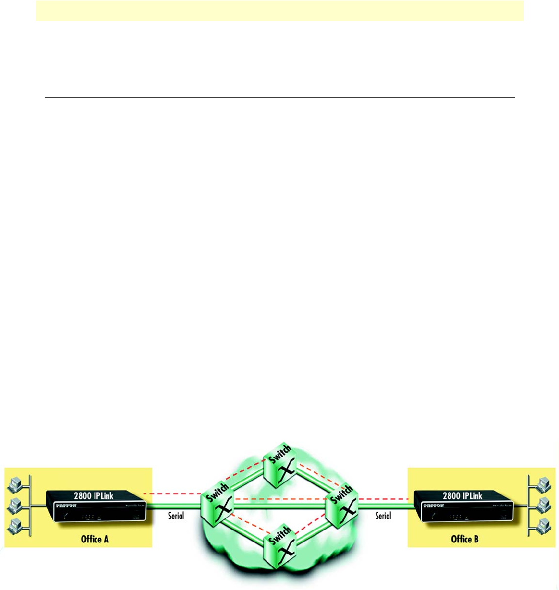
Branch-Office virtual private network over Frame Relay service
Featuring VPN tunneling combined with built-in frame-relay support and a selection of standard serial inter-
faces on-board, the OnSite 2800 Series offers the remote-branch office a secure, private and prioritized net-
work connection to another location over virtually any available network service and any standard WAN
interface.
Figure 6. Branch-office virtual private network over a Frame-Relay service network
Figure 6 shows a branch-to-branch VPN connection through a frame-relay service network as delivered on
serial lines. The OnSite 2800 Series can support a similar scenario with network service delivered via V.35 or

Applications overview 24
OnSite 2800 Series User Manual 1 • General information
X.21 serial interfaces, or an Ethernet WAN interface. For remote sites where PPP service is available, the 2800
Series also supports PPP network access over all the standard WAN interface options mentioned above.
In this specific application, all traffic between the branch and corporate offices is carried in an IPSec tunnel. All
of the IPSec VPN traffic is encapsulated in Frame Relay for transport over the Frame Relay service network.
The serial port is configured for Frame Relay.
To configure this application, you need to configure the following features:
•The serial port with Frame Relay as the encapsulation protocol
•An IPSec VPN between the two endpoints.
See chapter 4 on page 44 to configure the serial port and chapter 6 on page 67 to configure the VPN.
Corporate multi-function virtual private network
The OnSite 2800 Series can deliver both private corporate intranet service and public Internet access to multi-
ple remote sites by leveraging OnSite’s multiple frame-relay PVC support (see figure 7). The enterprise enjoys
the benefits of secure multi-office virtual private networking with QoS for prioritized traffic flow for mission-
critical information.
Figure 7. Corporate multi-function virtual private network

Applications overview 25
OnSite 2800 Series User Manual 1 • General information
In figure 7, the blue pipes represent VPN connections for private traffic within the corporate intranet, while
the green pipes represent the Internet traffic. The red pipe is a Frame Relay PVC transporting Internet traffic
and private corporate traffic over the VPN. Each of the three remote sites is connected with headquarters via an
OnSite VPN router. Each remote site can take advantage of the most convenient and locally available interface
the WAN service can offer, whether X.21, or V.35.
The corporate multi-function application carries two types of traffic between each remote office and corpo-
rate’s central office:
•Private corporate traffic (the intranet/extranet)
•Internet traffic
The service provider offers a Frame Relay network for access, so both the private corporate traffic and the Inter-
net traffic is transported over a Frame Relay PVC with one DLCI. The corporate traffic is transported within
IPSec VPN that is in the Frame Relay PVC. The separation of corporation and Internet traffic is managed by
using an ACL using IP addresses as the watershed.
To configure this application, you must configure the following features:
•A serial Frame Relay link as the WAN service which will carry both private corporate traffic and public
Internet traffic
•An IPSec VPN for private corporate traffic
•An ACL to distinguish between the two types of traffic so only the private corporate traffic is carried over
the VPN.
See chapter 4 on page 44 to configure the serial port, chapter 6 on page 67 to configure the VPN, and chapter
7 on page 79 to configure the ACL. Chapter 8 on page 93 provides more in-depth explanations of scheduling
various types of traffic. Various techniques are also described, including QoS and TOS.

26
Chapter 2 Hardware installation
Chapter contents
Planning the installation.......................................................................................................................................27
Installation checklist ......................................................................................................................................28
Site log ...........................................................................................................................................................29
Network information .....................................................................................................................................29
Network Diagram .....................................................................................................................................29
IP related information ....................................................................................................................................29
Software tools ................................................................................................................................................29
Power source ..................................................................................................................................................29
Location and mounting requirements ............................................................................................................30
Installing the VPN router .....................................................................................................................................30
Mounting the VPN router ..............................................................................................................................30
Connecting cables ..........................................................................................................................................30
Installing the Ethernet cable .....................................................................................................................30
Installing the serial WAN cable ...............................................................................................................31
Installing the V.35 interface cable ..................................................................................................... 32
Installing the X.21 interface cable ..................................................................................................... 33
Installing the T1/E1 twisted pair cables............................................................................................. 34
Installing the E1 dual coaxial cables.................................................................................................. 35
Connecting to external power source .......................................................................................................36

Planning the installation 27
OnSite 2800 Series User Manual 2 • Hardware installation
Planning the installation
Before you start the actual installation, we strongly recommend that you gather all the information you will
need to install and setup the device. See table 3 for an example of what pre-installment checks you might need
to carry out. Completing the pre-installation checks enables you to install and set up your VPN router within
an existing network infrastructure with confidence.
Note
When setting up your VPN router you must consider cable length
limitations, and potential electromagnetic interference (EMI) as
defined by the applicable local and international regulations. Ensure
that your site is properly prepared before beginning installation.
Before installing the VPN Router device, the following tasks should be completed:
•Create a network diagram (see section “Network information” on page 29)
•Gather IP related information (see section “IP related information” on page 29 for more information)
•Install the hardware and software needed to configure the OnSite router. (See section “Software tools”
on page 29)
•Verify power source reliability (see section “Power source” on page 29).
When you finish preparing for your VPN Router installation, go to section “Installing the VPN router” on
page 30 to install the device.
The mains outlet that is utilized to power the equipment must be
within 1 meter (3 feet) of the device and shall be easily accessible.
CAUTION

Planning the installation 28
OnSite 2800 Series User Manual 2 • Hardware installation
Installation checklist
The installation checklist (see table 3) lists the tasks for installing an OnSite 2800 Series VPN Router. Make a
copy of this checklist and mark the entries as you complete each task. For each OnSite 2800 Series VPN
Router, include a copy of the completed checklist in your site log.
Table 3. Installation checklist
Task Verified by Date
Network information available & recorded in site log
Environmental specifications verified
Site power voltages verified
Installation site pre-power check completed
Required tools available
Additional equipment available
All printed documents available
OnSite release & build number verified
Rack, desktop, or wall mounting of chassis completed
Initial electrical connections established
ASCII terminal attached to console port
Cable length limits verified
Initial configuration performed
Initial operation verified
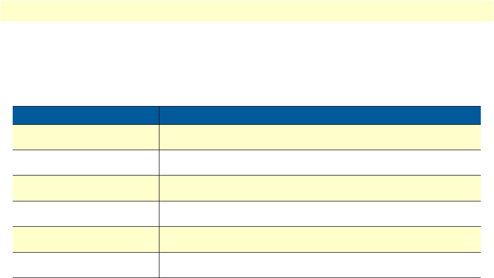
Planning the installation 29
OnSite 2800 Series User Manual 2 • Hardware installation
Site log
Patton recommends that you maintain a site log to record all actions relevant to the system, if you do not
already keep such a log. Site log entries should include information such as listed in table 4.
Network information
When planning your installation there are certain network-connection considerations that you should take into
account. The following sections describe such considerations for several types of network interfaces.
Network Diagram
Draw a network overview diagram that displays all neighboring IP nodes, connected elements and telephony
components.
IP related information
Before you can set up the basic IP connectivity for your OnSite 2800 Series you should have the
following information:
•IP addresses and subnet masks used for Ethernet LAN and WAN ports
•IP addresses and subnet masks used for the V.35 or X.21 serial WAN port
•IP addresses and subnet masks used for the T1/E1 WAN port
•IP addresses of central TFTP Server used for configuration upload and download
•Login and password for PPPoE Access.
Software tools
You will need a PC (or equivalent) with a VT-100 emulation program (e.g. HyperTerminal) to configure the
software on your OnSite VPN Router.
Power source
If you suspect that your AC power is not reliable, for example if room lights flicker often or there is machinery
with large motors nearby, have a qualified professional test the power. Install a power conditioner if necessary.
Table 4. Sample site log entries
Entry Description
Installation Make a copy of the installation checklist and insert it into the site log
Upgrades and maintenance Use the site log to record ongoing maintenance and expansion history
Configuration changes Record all changes and the reasons for them
Maintenance Schedules, requirements, and procedures performed
Comments Notes, and problems
Software Changes and updates to OnSite software

Installing the VPN router 30
OnSite 2800 Series User Manual 2 • Hardware installation
Location and mounting requirements
The OnSite VPN Router is intended to be placed on a desktop or similar sturdy, flat surface that offers easy
access to the cables. Allow sufficient space at the rear of the chassis for cable connections. Additionally, you
should consider the need to access the unit for future upgrades and maintenance.
Installing the VPN router
OnSite VPN Router installation consists of the following:
•Placing the device at the desired installation location (see section “Mounting the VPN router” on page 30)
•Installing the interface and power cables (see section “Connecting cables” on page 30)
When you finish installing the OnSite router, go to chapter 3, “Getting started with the OnSite Managed VPN
Router” on page 38.
Mounting the VPN router
Place the VPN Router on a desktop or similar sturdy, flat surface that offers easy access to the cables. The VPN
Router should be installed in a dry environment with sufficient space to allow air circulation for cooling.
Note
For proper ventilation, leave at least 2 inches (5 cm) to the left, right,
front, and rear of the OnSite VPN Router.
Connecting cables
Installing VPN Router cables takes place in the following order:
1. Installing the 10/100 Ethernet port cable or cables (see section “Installing the Ethernet cable” on page 30)
2. Installing the cables:
a. V.35 or X.21 serial WAN cable (see section “Installing the serial WAN cable” on page 31) or
b. T1/E1 WAN cable (see section “Installing the serial WAN cable” on page 31)
3. Installing the power input (see section “Connecting to external power source” on page 36)
Installing the Ethernet cable
The OnSite 2800 Series has automatic MDX (auto-cross-over) detection and configuration on the Ethernet
ports. Any of the two ports (five on the Model 2805 and three on the Model 2823) can be connected to a host
or hub/switch with a straight-through wired cable (see figure 1). Ethernet devices (10Base-T or 100Base-T) are
Do not work on the system or connect or disconnect cables during periods of
lightning activity.
The interconnecting cables must be acceptable for external use
and must be rated for the proper application with respect to volt-
age, current, anticipated temperature, flammability, and
mechanical serviceability.
WARNING
CAUTION
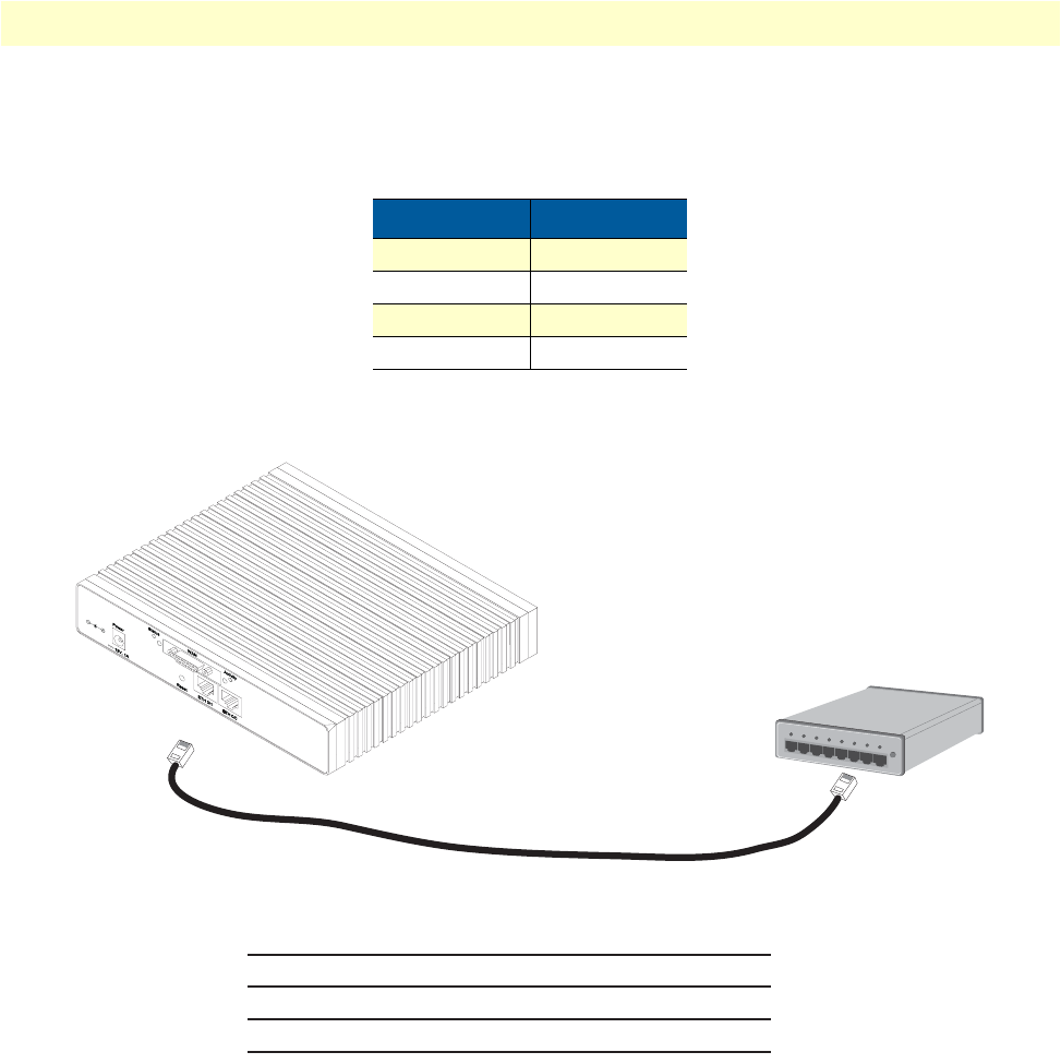
Installing the VPN router 31
OnSite 2800 Series User Manual 2 • Hardware installation
connected to the OnSite’s Ethernet ports (see table 5 for port pin-out listing) via a cable terminated with RJ-45
plugs.
Note
Pins not listed are not used.
Figure 1. Connecting an OnSite 2800 Series device to a hub
Installing the serial WAN cable
The OnSite 2800 Series is available with the following serial interfaces:
•V.35 (DB-25)—Model 2835, see section “Installing the V.35 interface cable” on page 32 for details on
installing the interface cable
•X.21 (DB-15)—Model 2821, see section “Installing the X.21 interface cable” on page 33 for details on
installing the interface cable
•T1/E1 (RJ48C connectors)—Model 2803, see section “Installing the T1/E1 twisted pair cables” on page 34
for details on installing the twisted pair cable
Table 5. Ethernet 10/100Base-T (RJ-45) port pin-outs
Pin Signal
1TX+
2TX-
3RX+
6RX-
Hub
Straight-through cable
RJ-45, male
Tx+
Tx-
Rx+
Rx-
1
2
3
6
RJ-45, male
1 Rx+
2 Rx-
3 Tx+
6 Tx-
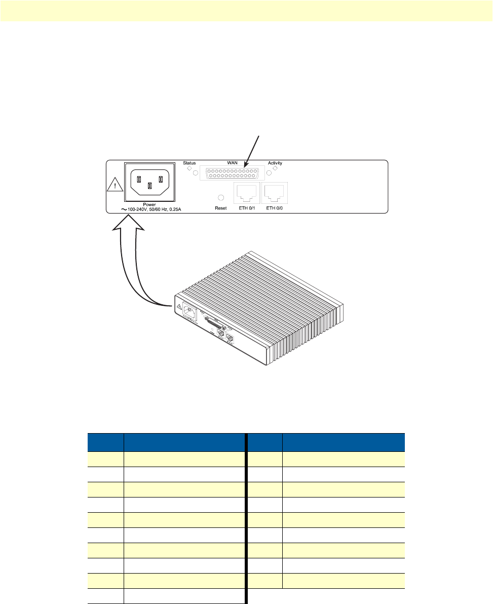
Installing the VPN router 32
OnSite 2800 Series User Manual 2 • Hardware installation
•E1 (Dual coaxial connectos)—Model 2803, see section “Installing the E1 dual coaxial cables” on page 35
for details on installing the coaxial cables
Installing the V.35 interface cable. The OnSite Model 2835 comes with a V.35 interface presented on a DB-
25 female connector (see figure 2).
Figure 2. Rear view of the router showing location of V.35 interface connector
The signal pin-outs for the Model 2835 V.35 interface are shown in table 6.
Table 6. Signal pin-outs for the V.35 interface on the OnSite 2800
Pin Signal Pin Signal
1Frame Ground 12 TXCb
2TXDa 14 TXDb
3RXDa 15 RXCa
4RTS 16 RXDb
5CTS 17 RXCa
6DSR 18 LL
7Signal Ground 20 DTR
8DCD 21 RL
9RXCb 24 EXTCa
11 EXTCb
V.35 serial port connector
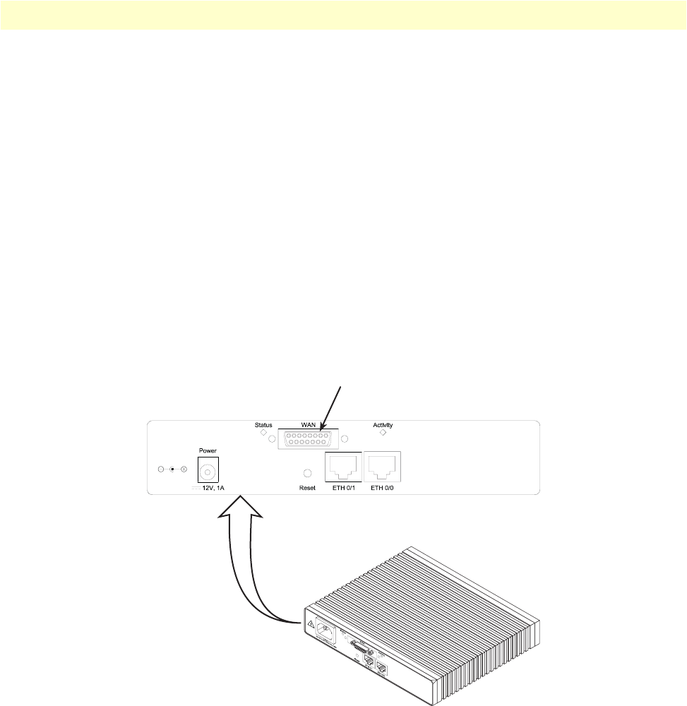
Installing the VPN router 33
OnSite 2800 Series User Manual 2 • Hardware installation
The router’s V.35 interface is wired as a DTE. No DCE configuration is possible. If you are directly connect-
ing the router’s V.35 interface to third-party equipment that cannot be configured as a DCE, you must use a
tail-circuit cable. You can purchase a tail-circuit cable from a datacom-supply vendor. A tail-circuit cable will
cross-over the necessary V.35 signals so that the two DTE interfaces can communicate.
Note
Some third-party equipment will not be able to work properly in
DTE-to-DTE configurations even when using a tail-circuit cable.
Please refer to your third party equipment user manual for informa-
tion on DTE-to DTE operation.
The router’s V.35 interface requires a cable with a male DB-25 connector. Attach the male DB-25/M35 con-
nector of the V.35 cable to the female DB-25 connector on the router. Attach the other end of the cable to the
V.35 connector on local V.35 modem or multiplexer device.
Installing the X.21 interface cable. The OnSite Model 2821 comes with a V.35 interface presented on a DB-
25 female connector (see figure 3).
Figure 3. Rear view of the router showing location of X.21 interface connector
X.21 serial port connector
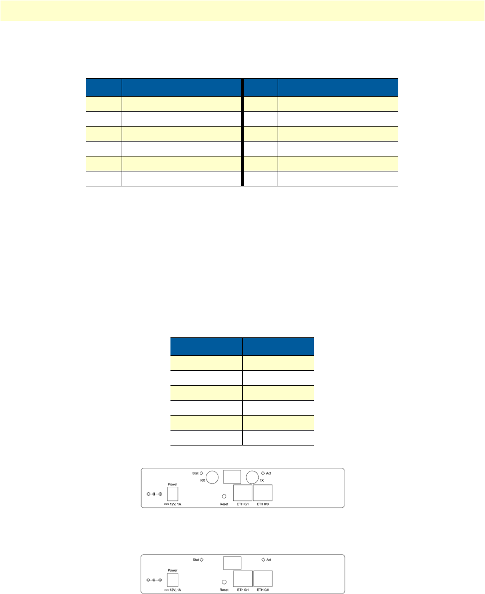
Installing the VPN router 34
OnSite 2800 Series User Manual 2 • Hardware installation
The signal pin-outs for the Model 2821 X.21 interface are shown in table 6.
The the router’s X.21 interface is wired as a DCE. No DTE configuration is possible. The router’s X.21 inter-
face requires a cable with a male DB-15 connector. Attach the male DB-15 connector of the X.21 cable to the
female DB-15 connector on the router. Attach the other end of the cable to the X.21 connector on local
modem or multiplexer device.
Installing the T1/E1 twisted pair cables. The PRI is usually connected to a PBX or switch (local exchange
(LE)). Type and pin-outs of these devices vary depending on the manufacturer. In most cases, a straight-
through RJ-48C to RJ-48C can be used to connect to the PRI (see for E1 RJ-48C pin-out listing) with a PBX.
A cross-over cable is required to connect to an NT1, as illustrated in .
Figure 4. Rear panel of 2803K/EUI
Figure 5. Rear panel of 2803T/EUI
Table 7. Signal pin-outs for the X.21 interface on the OnSite 2800
Pin Signal Pin Signal
1Frame Ground 8Signal Ground
2TXDa 9TXDb
3CNTa 10 CNTb
4RXDa 11 RXDb
5INDa 12 INDb
6SETa 13 SETb
Table 8. RJ-48C receptacle
Pin Signal
1TX tip
2TX ring
3TX shield
4RX tip
5RX ring
6RX shield
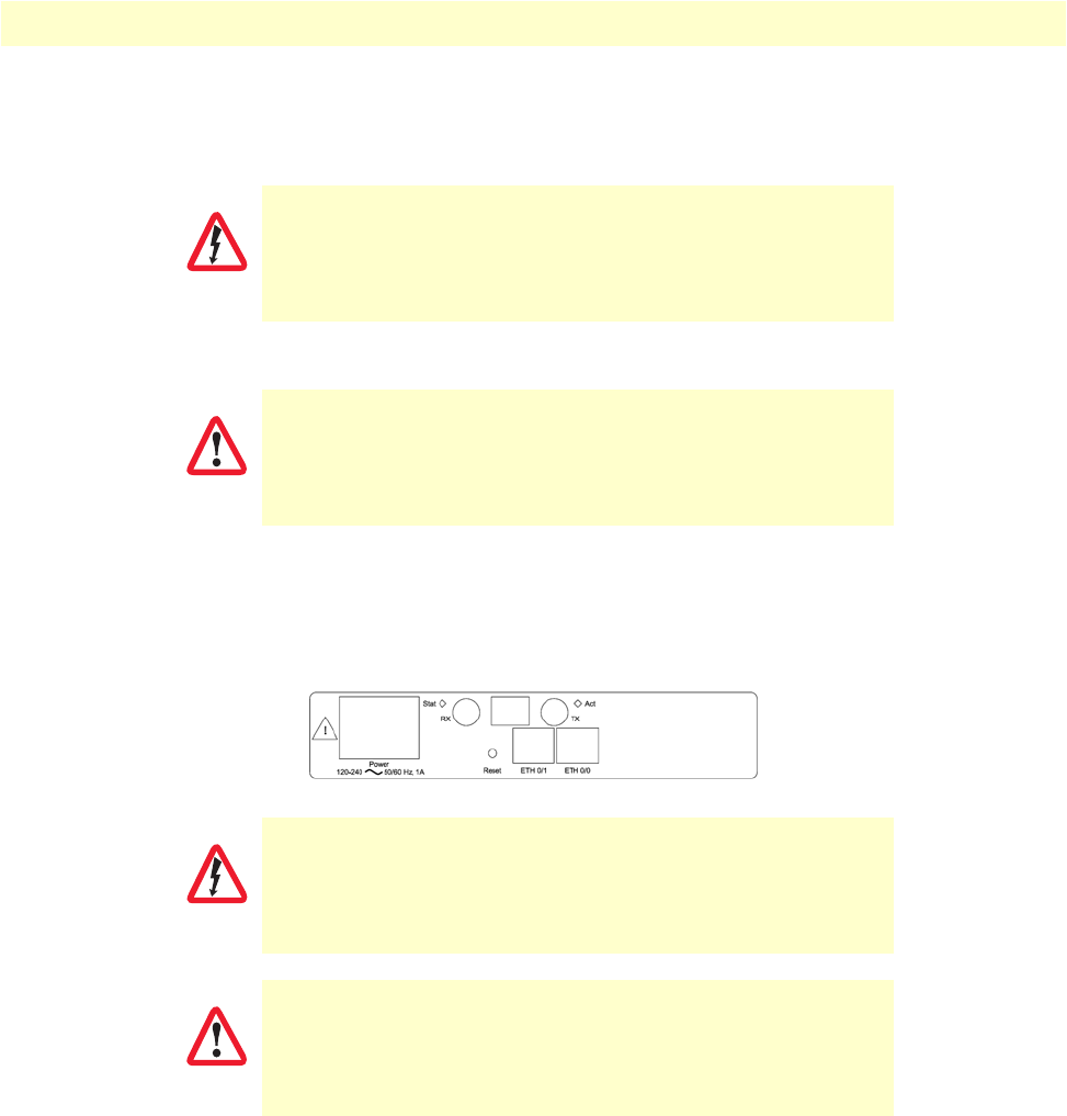
Installing the VPN router 35
OnSite 2800 Series User Manual 2 • Hardware installation
Note
Pins not listed are not used.
Installing the E1 dual coaxial cables. If the PBX or switch connection provides dual coaxial cables for the E1
connection, the transmit cable from the PBX/switch connects to the RX coaxial connector. Similarly, the
receive cable from the PBX/switch connects to the TX coaxial connector.
Figure 6. Rear panel of 2803K/UI
Hazardous network voltages are present in the PRI cables. If you detach the
cable, detach the end away from the OnSite first to avoid possible electric
shock. Network hazardous voltages may be present on the device in the area
of the PRI port, regardless of power being on or off.
To prevent damage to the system, make certain you connect the
PRI cable to the PRI port only and not to any other RJ type recep-
tacle.
WARNING
CAUTION
WARNING
CAUTION
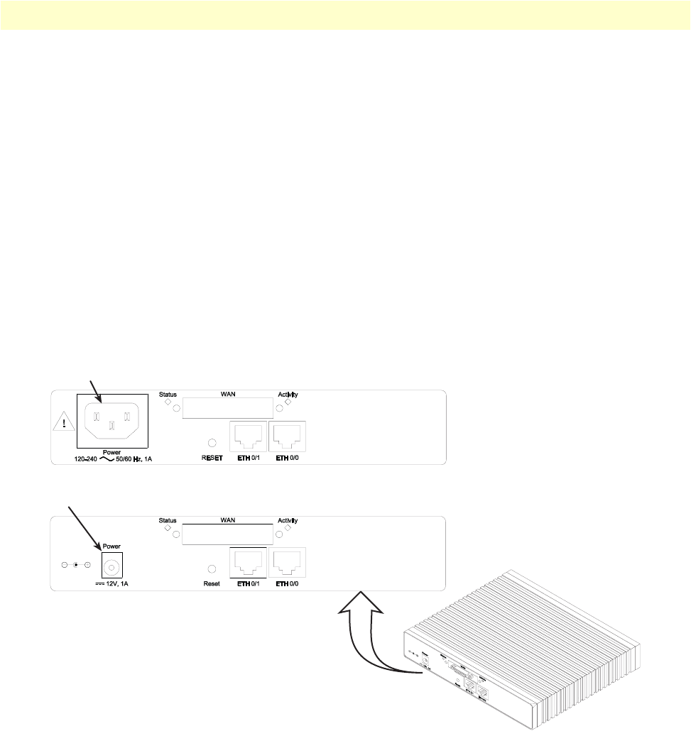
Installing the VPN router 36
OnSite 2800 Series User Manual 2 • Hardware installation
Connecting to external power source
The VPN Router comes with one of the following power supply options as best-suited to the expected installa-
tion environment:
•120/140VAC internal power supply (designated by the model code extension UI)
•120/140VAC external power supply (designated by the model code extension EUI)
•120VAC external power supply (designated by the model code extension E)
This section below describes installing the power cord into the VPN Router. Do the following:
Note
Do not connect the power cord to the power outlet at this time.
1. If your unit is equipped with an internal power supply, go to step 2. Otherwise, insert the barrel type con-
nector end of the AC power cord into the external power supply connector (see figure 7).
2. Insert the female end of the power cord into the internal power supply connector (see figure 7).
Figure 7. Power connector location on rear panel
External power supply connector accepts 12 VDC, 1 A, from external AC adapter (some models accept
+5VDC, see Appendix B, “Specifications” for details)
lnternal power supply connector accepts 100–240 VAC, 50/60 Hz, up to 1 A
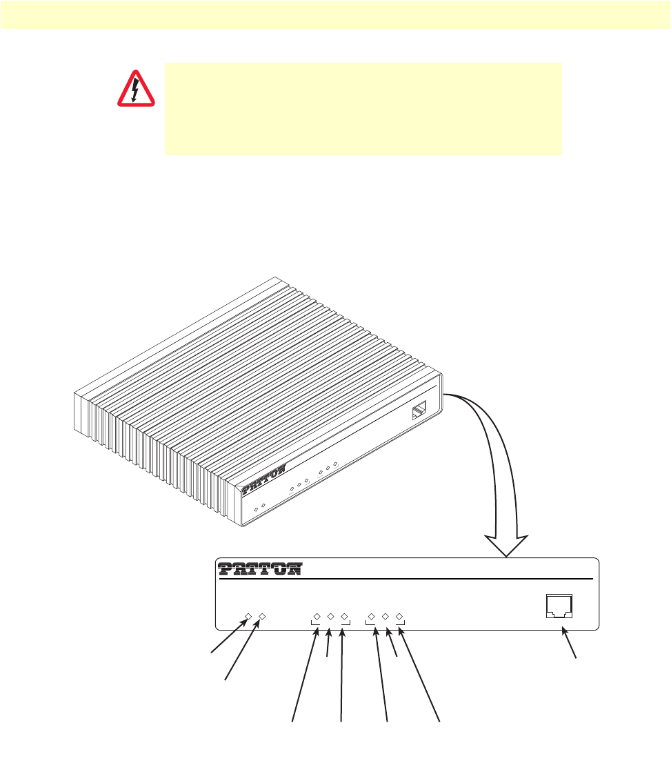
Installing the VPN router 37
OnSite 2800 Series User Manual 2 • Hardware installation
3. Verify that the AC power cord included with your VPN Router is compatible with local standards. If it is
not, refer to chapter 10, “Contacting Patton for assistance” on page 114 to find out how to replace it with
a compatible power cord.
4. Connect the male end of the power cord to an appropriate power outlet.
Figure 8. VPN Router front panel LEDs and Console port locations (OnSite 2835 shown)
5. Verify that the green Power LED is lit (see figure 8).
Congratulations, you have finished installing the OnSite VPN Router! Now go to chapter 3, “Getting started
with the OnSite Managed VPN Router” on page 38.
The UI and EUI power supplies automatically adjust to accept an
input voltage from 100 to 240 VAC (50/60 Hz).
Verify that the proper voltage is present before plugging the
power cord into the receptacle. Failure to do so could result in
equipment damage.
CAUTION
Link
100M
Activity
Enet 0 Console
IPLink VPN Router
Run
Link
100M
Activity
Enet 1
Power
Link
100M
Activity
Enet 0
IPLink VPN Router
Run
Link
100M
Activity
Enet 1
Power
Console
Console
Console
port
Power
Enet 0
Link
Run
Enet 0
100M
Enet 0
Activity Enet 1
Link
Enet 1
100M
Enet 1
Activity

38
Chapter 3 Getting started with the OnSite
Managed VPN Router
Chapter contents
Introduction ..........................................................................................................................................................39
1. Configure IP address ........................................................................................................................................40
Power connection and default configuration .................................................................................................40
Connect with the serial interface ...................................................................................................................40
Login ..............................................................................................................................................................41
Changing the IP address ................................................................................................................................41
2. Connect the OnSite VPN Router to the network..............................................................................................42
3. Load configuration ...........................................................................................................................................42
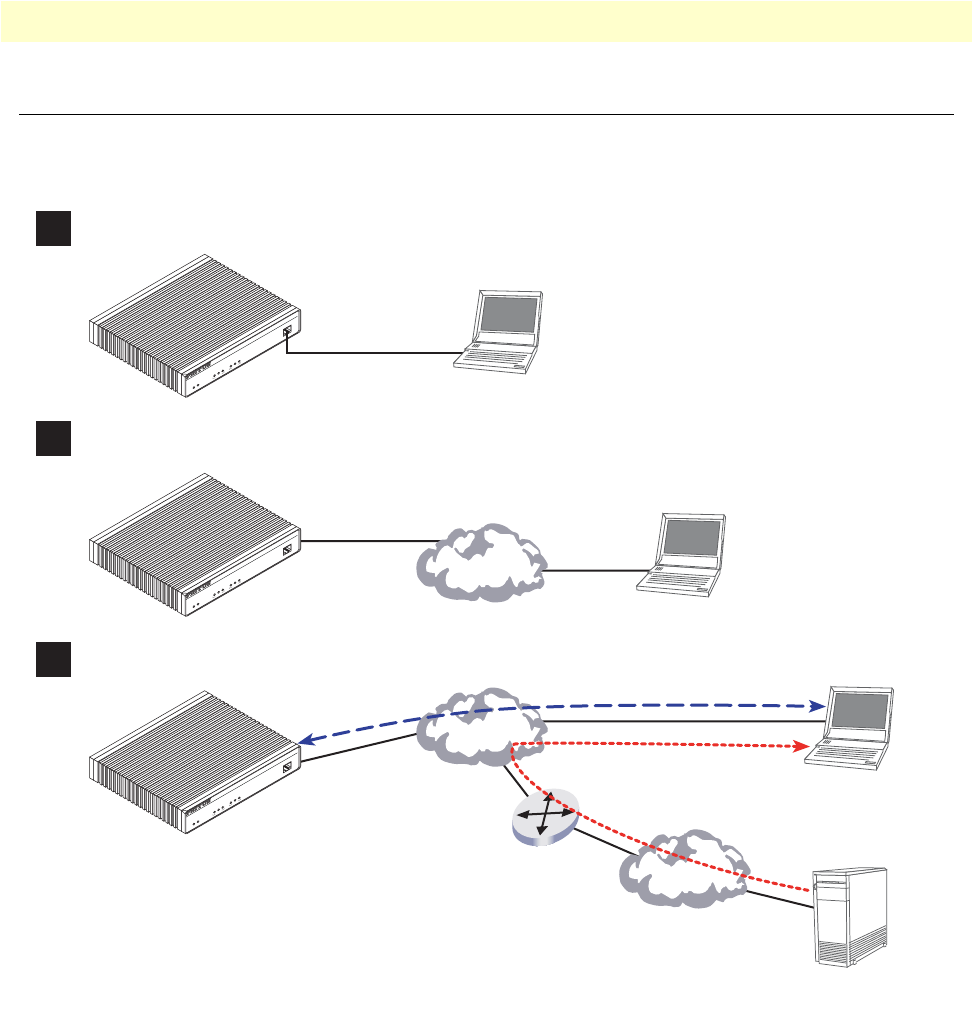
Introduction 39
OnSite 2800 Series User Manual 3 • Getting started with the OnSite Managed VPN Router
Introduction
This chapter leads you through the basic steps to set up a new OnSite VPN Router. Figure 9 show the main
steps for setting up a new OnSite VPN Router.
Figure 9. Steps for setting up a new OnSite VPN Router
Link
100M
Activity
Enet 0
IPLink VPN Router
Run
Link
100M
Activity
Enet 1
Power
Console
1Configure IP address
2Connect the IPLink VPN Router to the network
3Load configuration
Console port
Serial
interface
PC or workstation
with VT-100
emulation terminal
Ethernet interface
ETH0 Network
interface
PC or workstation
or VT-100 emulation
terminal
Network
2. Modify configuration
Network
Internet
3. Load configuration
1. Download configuration example
Patton Web server
with configuration examples
Link
100M
Activity
Enet 0
IPLink VPN Router
Run
Link
100M
Activity
Enet 1
Power
Console
Link
100M
Activity
Enet 0
IPLink VPN Router
Run
Link
100M
Activity
Enet 1
Power
Console
Note You can manually configure the IPLink
Router. You do not have to load a
configuration file.
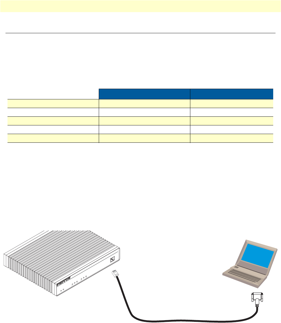
1. Configure IP address 40
OnSite 2800 Series User Manual 3 • Getting started with the OnSite Managed VPN Router
1. Configure IP address
Power connection and default configuration
First the OnSite VPN Router must be connected to the mains power supply with the power cable. Wait until
the
Run
LED stops blinking and lights constantly. Now the OnSite VPN Router is ready.
The factory default configuration for the Ethernet interface IP addresses and network masks are listed in table 9.
All Ethernet interfaces are activated upon power-up.
If these addresses match with those of your network, go to section “2. Connect the OnSite VPN Router to the
network” on page 42. Otherwise, refer to the following sections to change the addresses and network masks.
Connect with the serial interface
The Console port is wired as an EIA-561, RS-232 port. Use the included Model 16F-561 adapter and cable (see
figure 10) between the OnSite VPN Router’s Console port and a PC or workstation’s RS-232 serial interface.
Activate the terminal emulation program on the PC or workstation that supports the serial interface (e.g.
HyperTerm).
Figure 10. Connecting to the terminal
Terminal emulation program settings:
•9600 bps
•no parity
•8 bit
Table 9. Factory default IP address and network mask configuration
IP Address Network Mask
Interface Ethernet 0/0 (ETH0) 172.16.40.1 255.255.0.0
Interface Ethernet 0/1 (ETH1) 192.168.1.1 255.255.255.0
Interface Ethernet 0/2 (ETH2) x.x.x.x x.x.x.x
Interface Ethernet 0/3 (ETH3) x.x.x.x x.x.x.x
Interface Ethernet 0/4 (ETH4) x.x.x.x x.x.x.x
Link
100M
Activity
Enet 0
IPLink VPN Router
Run
Link
100M
Activity
Enet 1
Power
Console
Serial Terminal
Note A Patton Model 16F-561 RJ45 to DB-9 adapter is included with
each IPLink 2800 Series device

1. Configure IP address 41
OnSite 2800 Series User Manual 3 • Getting started with the OnSite Managed VPN Router
•1 stop bit
•No flow control
Login
Accessing your OnSite VPN Router via the local console port (or via a Telnet session) causes the login screen
to display. Type the factory default login: administrator and leave the password empty. Press the Enter key after
the password prompt.
login:administrator
password: <Enter>
172.16.40.1>
After you have successfully logged in you are in the operator execution mode, indicated by > as command line
prompt. With the commands enable and configure you enter the configuration mode.
172.16.40.1>enable
172.16.40.1#configure
172.16.40.1(cfg)#
Changing the IP address
Select the context IP mode to configure an IP interface.
172.16.40.1(cfg)#context ip router
172.16.40.1(ctx-ip)[router]#
Now you can set your IP address and network mask for the interface eth0. Within this example a class C net-
work (172.16.1.0/24) is assumed. The IP address in this example is set to 172.16.1.99 (you should set this to
an unused IP address on your network).
172.16.40.1(ctx-ip)[router]#interface eth0
172.16.40.1(if-ip)[eth0]#ipaddress 172.16.1.99 255.255.255.0
2002-10-29T00:09:40 : LOGINFO : Link down on interface eth0.
2002-10-29T00:09:40 : LOGINFO : Link up on interface eth0.
172.16.1.99(if-ip)[eth0]#
Copy this modified configuration to your new start-up configuration. Upon the next start-up the system will
initialize itself using the modified configuration.
172.16.1.99(if-ip)[eth0]#copy running-config startup-config
172.16.1.99(if-ip)[eth0]#
The OnSite VPN Router can now be connected with your network.
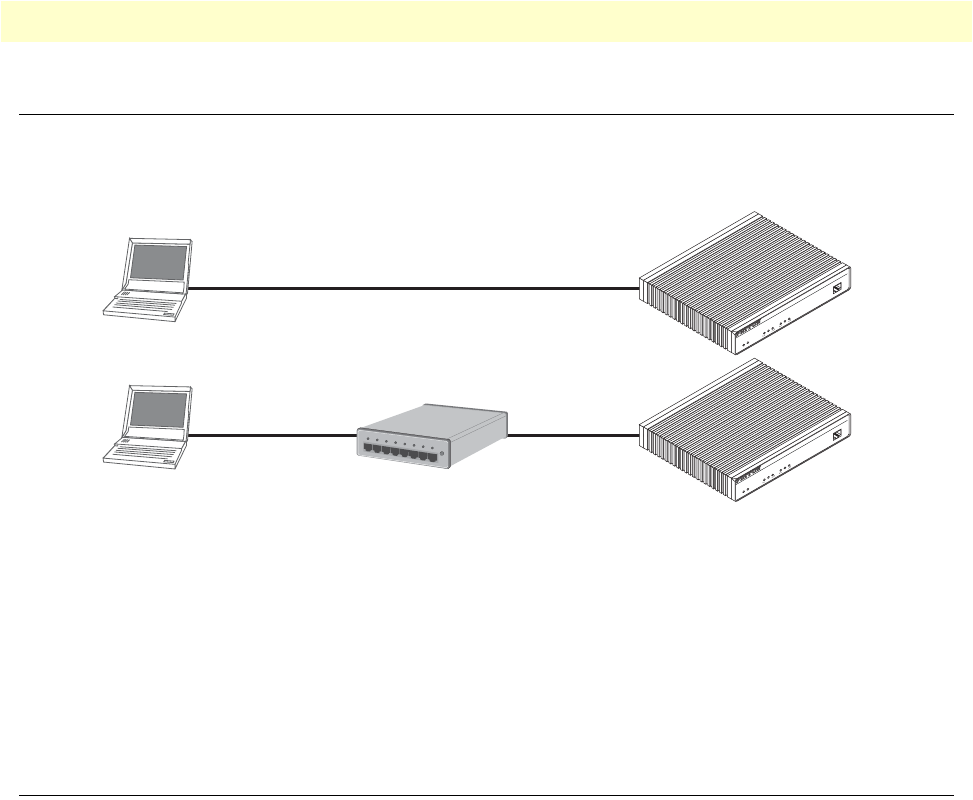
2. Connect the OnSite VPN Router to the network 42
OnSite 2800 Series User Manual 3 • Getting started with the OnSite Managed VPN Router
2. Connect the OnSite VPN Router to the network
Depending whether you connect the OnSite VPN Router to a host directly or via a hub or switch either
straight-through wired or cross-over cables must be used (see figure 11).
Figure 11. Connecting the OnSite VPN Router to the network
You can check the connection with the ping command to another host on the local LAN.
172.16.1.99(if-ip)[eth0]#ping <IP Address of the host>
Respectively from the host: ping 172.16.1.99
Note
To ping outside your local LAN, you will need to configure the
default gateway.
3. Load configuration
Patton provides a collection of configuration templates on the CD-ROM that came with the OnSite device,
one of which may be similar enough to your application that you can use it to speed up configuring the OnSite
router. Simply download the configuration note that matches your application to your PC. Adapt the configu-
ration as described in the configuration note to your network (remember to modify the IP address) and copy
the modified configuration to a TFTP server. The OnSite VPN Router can now load its configuration from
this server.
In this example we assume the TFTP server on the host with the IP address 172.16.1.11 and the configuration
named IPL.cfg in the root directory of the TFTP server.
172.16.1.99(if-ip)[eth0]#copy tftp://172.16.1.11/IPL.cfg startup-config
Download...100%
172.16.1.99(if-ip)[eth0]#
Network
interface ETH 0
Cross-over cable
IPLink Router
Host
Network
interface ETH 0
Straight-through
wired cable
IPLink Router
Host
Hub
Straight-through
wired cable
Link
100M
Activity
Enet 0
IPLink VPN Router
Run
Link
100M
Activity
Enet 1
Power
Console
Link
100M
Activity
Enet 0
IPLink VPN Router
Run
Link
100M
Activity
Enet 1
Power
Console

3. Load configuration 43
OnSite 2800 Series User Manual 3 • Getting started with the OnSite Managed VPN Router
After the OnSite VPN Router has been rebooted the new start up configuration will be activated.
172.16.1.99(if-ip)[eth0]#reload
Running configuration has been changed.
Do you want to copy the 'running-config' to the 'startup-config'?
Press 'yes' to store, 'no' to drop changes : no
Press 'yes' to restart, 'no' to cancel : yes
The system is going down

44
Chapter 4 Serial port configuration
Chapter contents
Introduction..........................................................................................................................................................45
Serial port configuration task list ...........................................................................................................................45
Disabling an interface .....................................................................................................................................45
Enabling an interface ......................................................................................................................................46
Configuring the encapsulation for Frame Relay ..............................................................................................47
Enter Frame Relay mode .................................................................................................................................48
Configuring the LMI type ...............................................................................................................................48
Configuring the keep-alive interval .................................................................................................................49
Entering Frame Relay PVC configuration mode .............................................................................................49
Configuring the PVC encapsulation type ........................................................................................................50
Binding the Frame Relay PVC to IP interface .................................................................................................50
Enabling a Frame Relay PVC ..........................................................................................................................52
Disabling a Frame Relay PVC .........................................................................................................................52
Displaying serial port information ...................................................................................................................53
Displaying Frame Relay information ...............................................................................................................54
Integrated service access ..................................................................................................................................55

Introduction 45
OnSite 2800 Series User Manual 4 • Serial port configuration
Introduction
This chapter provides an overview of the serial port and describes the tasks involved in its configuration
through the OnSite router, it includes the following sections:
•Serial port configuration task list
•Configuration tasks
•Examples
The V.35 standard is recommended for speeds up to 48 kbps, although in practice it is used successfully at 4
Mbps. The X.21 standard is recommended for data interfaces transmitting at rates up to 2 Mbps and is used
primarily in Europe and Japan.
The synchronous serial interface supports full-duplex operation and allows interconnection to various serial
network interface cards or equipment.
The OnSite device supports the Frame Relay protocol on the synchronous serial interface. Frame Relay is an
example of a packet-switched technology. Packet-switched networks enable end stations to dynamically share
the network medium and the available bandwidth. Variable-length packets are used for more efficient and flex-
ible transfers. These packets are then switched between the various network segments until the destination is
reached. Statistical multiplexing techniques control network access in a packet-switched network. The advan-
tage of this technique is that it provides more flexibility and more efficient use of bandwidth.
Serial port configuration task list
Perform the tasks in the following sections to configure a synchronous serial interface:
•Disabling an interface (see page 45)
•Enabling an interface (see page 46)
•Configuring the serial encapsulation type (see page 47)
•Entering Frame Relay mode (see page 48)
•Configuring the LMI type (see page 48)
•Configuring the keep-alive interval (see page 49)
•Entering Frame Relay PVC configuration mode (see page 49)
•Configuring the PVC encapsulation type (see page 50)
•Binding the Frame Relay PVC to IP interface (see page 50)
•Disabling a Frame Relay PVC (see page 52)
•Displaying Frame Relay information (see page 54)
Disabling an interface
Before you replace a compact serial cable or attach your OnSite to other serial equipment, use the shutdown
command to disable the serial interfaces. This prevents anomalies and hardware faults. When you shut down
an interface, it has the state CLOSED in the show port serial command display.

Serial port configuration task list 46
OnSite 2800 Series User Manual 4 • Serial port configuration
Note
Use the no shutdown command to enable the serial interface after
the configuration procedure.
This procedure describes how to shut down a serial interface
Mode: Administrator execution
Example: Disabling an interface
The example shows how to disable the built-in serial interface on slot 0 and port 0 of an OnSite router. Check
that State is set to CLOSED in the command output of show port serial.
2800(cfg)#port serial 0 0
2800(prt-ser)[0/0]#shutdown
2800(prt-ser)[0/0]#show port serial
Serial Interface Configuration
------------------------------
Port : serial 0 0 0
State : CLOSED
Hardware Port : V.35
Transmit Edge : normal
Port Type : DTE
CRC Type : CRC-16
Max Frame Length: 2048
Recv Threshold : 1
Encapsulation :
Enabling an interface
After configuring the serial interface or connecting other serial devices to your OnSite 2000, use the no shut-
down command to enable the serial interfaces again. When you enable an interface, it has the state OPENED
in the show port serial command display.
Note
Use the shutdown command to disable the serial interface for any
software or hardware configuration procedure.
This procedure describes how to enable a serial interface.
Mode: Administrator execution
Step Command Purpose
1node(cfg)#port serial slot port Selects the serial interface on slot and port
2node(prt-ser)[slot/port]#shutdown Shuts the selected interface down
3node(prt-ser)[slot/port]#show port serial Displays the serial interface configuration.
Step Command Purpose
1node(cfg)#port serial slot port Selects the serial interface on slot and port
2node(prt-ser)[slot/port]#no shutdown Enables the interface
3node(prt-ser)[slot/port]#show port serial Displays the serial interface configuration.

Serial port configuration task list 47
OnSite 2800 Series User Manual 4 • Serial port configuration
Example: Enabling an interface
The example shows how to enable the built-in serial interface on slot 0 and port 0 of an OnSite router. Check
that State is set to OPENED in the command output of show port serial.
2800(cfg)#port serial 0 0
2800(prt-ser)[0/0]#no shutdown
2800(prt-ser)[0/0]#show port serial
Serial Interface Configuration
------------------------------
Port : serial 0 0 0
State : OPENED
Hardware Port : V.35
Transmit Edge : normal
Port Type : DTE
CRC Type : CRC-16
Max Frame Length: 2048
Recv Threshold : 1
Encapsulation :
Configuring the encapsulation for Frame Relay
The synchronous serial interface supports the Frame Relay serial encapsulation method.
To set the encapsulation method used by a serial interface, use the encapsulation interface
configuration command.
This procedure describes how to set the encapsulation type of the serial interface for Frame Relay.
Mode: Administrator execution
Example: Configuring the serial encapsulation type
The following example enables Frame Relay encapsulation for the serial interface on slot 0 and port 0 of an
OnSite router. Check that in the command output of show port serial Encapsulation is set to framerelay.
2800(cfg)#port serial 0 0
2800(prt-ser)[0/0]#encapsulation framerelay
2800(prt-ser)[0/0]#show port serial
Serial Interface Configuration
------------------------------
Port : serial 0 0 0
State : CLOSED
Hardware Port : V.35
Step Command Purpose
1node(cfg)#port serial slot port Selects the serial interface on slot and
port.
2node(prt-ser)[slot/port]#[no] encapsulation {
framerelay | ppp }
Sets the encapsulation type for the
selected interface.
3node(prt-ser)[slot/port]#show port serial Displays the serial interface configuration.

Serial port configuration task list 48
OnSite 2800 Series User Manual 4 • Serial port configuration
Transmit Edge : normal
Port Type : DTE
CRC Type : CRC-16
Max Frame Length: 2048
Recv Threshold : 1
Encapsulation : framerelay
Enter Frame Relay mode
This section describes how to configure Frame Relay on the serial interface of an OnSite router, after setting
the basic serial interface parameters according to the previous sections.
This procedure describes how to enter the Frame Relay configuration mode
Mode: Administrator execution
Example: Enter Frame Relay mode
The following example shows how to enter into the Frame Relay configuration mode for the serial interface on
slot 0 and port 0 of an OnSite router.
2800(cfg)#port serial 0 0
2800(prt-ser)[0/0]#framerelay
2800(frm-rel)[0/0]#
Configuring the LMI type
For a Frame Relay network, the line protocol is the periodic exchange of local management interface (LMI)
packets between the OnSite device and the Frame Relay provider equipment. If the OnSite device is attached
to a public data network (PDN), the LMI type must match the type used on the public network.
You can set one of the following three types of LMIs on the OnSite devices:
•ansi for ANSI T1.617 Annex D,
•gof for Group of 4, which is the default for Cisco LMI, and
•itu for ITU-T Q.933 Annex A.
This procedure describes how to set the LMI type.
Mode: Frame Relay
Example: Configuring the LMI type
The following example sets the LMI type to ANSI T1.617 Annex D for Frame Relay over the serial interface
on slot 0 and port 0.
Step Command Purpose
1node(cfg)#port serial slot port Selects the serial interface on slot and port
2node(prt-ser)[slot/port]#framerelay Enters the Frame Relay configuration mode
3node(frm-rel)[slot/port]# Displays the Frame Relay configuration mode prompt
Step Command Purpose
1node(frm-rel)[slot/port]#lmi-type {ansi | gof | itu} Sets the LMI type

Serial port configuration task list 49
OnSite 2800 Series User Manual 4 • Serial port configuration
2800(cfg)#port serial 0 0
2800(prt-ser)[0/0]#framerelay
2800(frm-rel)[0/0]#lmi-type ansi
Configuring the keep-alive interval
A keep-alive interval must be set to configure the LMI. By default, this interval is 10 seconds and, according to
the LMI protocol, must be less than the corresponding interval on the switch. The keep-alive interval in sec-
onds, which is represented by number, has to be in the range from 1 to 3600.
This procedure describes how to set the keep-alive interval
Mode: Frame Relay
To disable keep-alives on networks that do not utilize LMI, use the no keepalive interface
configuration command.
Example: Configuring the keep-alive interval
The following example sets the keepalive interval to 10 seconds for Frame Relay over the serial interface on slot
0 and port 0 of an OnSite router.
2800(cfg)#port serial 0 0
2800(prt-ser)[0/0]#framerelay
2800(frm-rel)[0/0]#keepalive 10
Entering Frame Relay PVC configuration mode
The permanent virtual circuit (PVC) is a virtual circuit that is permanently established. PVCs save bandwidth associ-
ated with circuit establishment and tear down in situations where certain virtual circuits must exist all the time.
The Frame Relay network provides a number of virtual circuits that form the basis for connections between
stations attached to the same Frame Relay network.
The resulting set of interconnected devices forms a private Frame Relay group, which may be either fully inter-
connected with a complete mesh of virtual circuits, or only partially interconnected.
In either case, each virtual circuit is uniquely identified at each Frame Relay interface by a Data Link Connection
Identifier (DLCI). In most circumstances, DLCIs have strictly local significance at each Frame Relay interface.
Assigning a DLCI to a specified Frame Relay sub interface on the OnSite is done in the PVC configuration
mode. The DLCI has to be in the range from 1 to 1022.
Note
A maximum of eight PVCs can be defined.
This procedure describes how to enter the PVC configuration.
Step Command Purpose
1node(frm-rel)[slot/port]#keepalive number Sets the LMI keep-alive interval
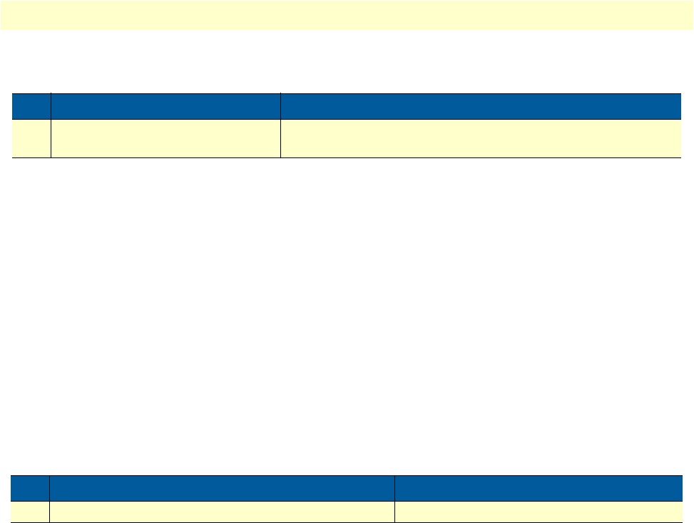
Serial port configuration task list 50
OnSite 2800 Series User Manual 4 • Serial port configuration
Mode: Frame Relay
Example: Entering Frame Relay PVC configuration mode
The following example enters the configuration mode for PVC with the assigned DLCI of 1 for Frame Relay
over the serial interface on slot 0 and port 0 of an OnSite router.
2800(cfg)#port serial 0 0
2800(prt-ser)[0/0]#framerelay
2800(frm-rel)[0/0]#pvc 1
2800(pvc)[1]#
Configuring the PVC encapsulation type
You must use the PVC configuration command encapsulation rfc1490 to set the encapsulation type to com-
ply with the Internet Engineering Task Force (IETF) standard (RFC 1490). Use this keyword when connect-
ing to another vendor’s equipment across a Frame Relay network.
This procedure describes how to set the encapsulation type to comply with RFC 1490
Mode: Frame Relay
Example: Configuring the PVC encapsulation type
The following example sets the encapsulation type to comply with RFC 1490 for PVC with the assigned DLCI
of 1 for Frame Relay over the serial interface on slot 0 and port 0 of an OnSite router.
2800(cfg)#port serial 0 0
2800(prt-ser)[0/0]#framerelay
2800(frm-rel)[0/0]#pvc 1
2800(pvc)[1]#encapsulation rfc1490
Binding the Frame Relay PVC to IP interface
A newly created permanent virtual circuit (PVC) for Frame Relay has to be bound to an IP interface for further
use. The logical IP interface has to be already defined and should be named according to the use of the serial
Step Command Purpose
1node(frm-rel)[slot/port]#pvc dlci Enters the PVC configuration mode by assigning a DLCI number
to be used on the specified sub interface
Step Command Purpose
1node(frm-rel)[slot/port]#encapsulation rfc1490 Sets RFC1490 PVC compliant encapsulation
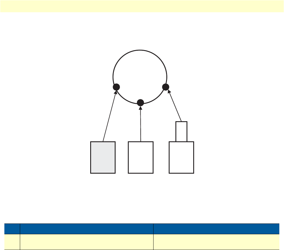
Serial port configuration task list 51
OnSite 2800 Series User Manual 4 • Serial port configuration
Frame Relay PVC. If serial Frame Relay PVC shall be used as WAN access, a suitable name for the logical IP
interface could be wan as in figure 12 below.
Figure 12. IP interface wan is bound to PVC 1 on port serial 0 0
This procedure describes how to bind the Frame Relay PVC DLCI on the serial interface to the logical IP
interface name, which is related to the IP context router.
Mode: PVC
Example: Binding the Frame Relay PVC to IP interface
The following example binds the Frame Relay PVC 1 to the IP interface wan of IP context router to the serial
interface on slot 0 and port 0 of an OnSite router.
2800(cfg)#port serial 0 0
2800(prt-ser)[0/0]#framerelay
2800(frm-rel)[0/0]#pvc 1
2800(pvc)[1]#bind interface wan router
Step Command Purpose
1node(pvc)[dlci]#bind interface name router Binds Frame Relay PVC dlci to the IP interface
name of IP context router
Context
IP
“router”
Port
Ethernet
0 0
Port
Ethernet
0 1
IP
interface
eth0
Port
Serial
0 0
IP
interface
eth1
IP
interface
wan
PVC

Serial port configuration task list 52
OnSite 2800 Series User Manual 4 • Serial port configuration
Enabling a Frame Relay PVC
After binding Framerelay PVC to an ip interface it must be enabled for packet processing. This procedure acti-
vates the PVC by opening the bound ip interface.
This procedure describes how to enable Framerelay PVC for packet processing
Mode: PVC
Example: Disabling a Frame Relay PVC
The following example enables Frame Relay PVC with the DLCI 1 on the serial interface on slot 0 and port 0.
2800(cfg)#port serial 0 0
2800(prt-ser)[0/0]#framerelay
2800(frm-rel)[0/0]#pvc 1
2800(pvc)[1]#no shutdown
Check the PVC 1 status using show running-config and verify that the entry no shutdown occurs in the con-
figuration part responsible for this PVC.
2800(pvc)[1]#show running-config
Running configuration:
#----------------------------------------------------------------#
# #
…
pvc 1
encapsulation rfc1490
bind interface wan router
no shutdown
Disabling a Frame Relay PVC
Frame Relay PVCs can be disabled whenever it is necessary. Be aware that disabling a specific PVC also dis-
ables the related serial interface and vice versa.
This procedure describes how to disable the Frame Relay PVC DLCI on the serial interface.
Mode: PVC
Example: Disabling a Frame Relay PVC
The following example disables Frame Relay PVC 1 on the serial interface on slot 0 and port 0 of an OnSite
router.
2800(cfg)#port serial 0 0
2800(prt-ser)[0/0]#framerelay
Step Command Purpose
1node(pvc)[dlci]#no shutdown Enables the Frame Relay PVC
Step Command Purpose
1node(pvc)[dlci]#shutdown Disables the Frame Relay PVC DLCI.

Serial port configuration task list 53
OnSite 2800 Series User Manual 4 • Serial port configuration
2800(frm-rel)[0/0]#pvc 1
2800(pvc)[1]#shutdown
Check the PVC 1 status by using show running-config and verify that the entry shutdown occurs in the con-
figuration part responsible for this PVC.
2800(pvc)[1]#show running-config
Running configuration:
#----------------------------------------------------------------#
# #
# 2500 #
…
pvc 1
encapsulation rfc1490
bind interface wan router
shutdown
exit
…
Displaying serial port information
The following example shows the commands used to display serial port configuration settings.
HDLC Driver: 0x8496b8
=====================
Slot: 0
Number of Ports: 1
HDLC Driver: 0x8496b8
=====================
Slot: 0
Number of Ports: 1
Port: serial 0 0 0
------------------
State: OPENED
Configuration
Hardware Port: X.21
Port Type: DCE
CRC: CRC-16
Transmit Edge: Normal
Max Frame Length: 1920
Baudrate: 64000 bps
Recv Threshold: 1

Serial port configuration task list 54
OnSite 2800 Series User Manual 4 • Serial port configuration
Displaying Frame Relay information
Since Frame Relay configuration for the serial interface is complex and requires many commands, it is helpful
to list the frame relay configuration on screen.
This procedure describes how to display the Frame Relay configuration settings for the serial interface.
Mode: Port serial
Example: Displaying Frame Relay information
The following example shows the commands used to display Frame Relay configuration settings.
2800>enable
2800#configure
2800(cfg)#show framerelay
Framerelay Configuration:
Port LMI-Type Keepalive Fragmentation
----------------------------------------------------------
serial 0 0 0 ansi 10 disabled
PVC Configuration:
Port DLCI State Fragment Encaps Binding
--------------------------------------------------------------
serial 0 0 0 1 open disabled rfc1490 wan@router
Step Command Purpose
1node(prt-ser)[slot/port]#show framerelay Displays Frame Relay information.

Serial port configuration task list 55
OnSite 2800 Series User Manual 4 • Serial port configuration
Figure 13. Typical Integrated Service Access Scenario with dedicated PVCs
Integrated service access
The example in figure 13 shows a typical integrated service access scenario, where different service providers are
accessed via permanent virtual circuits (PVCs) on Frame Relay over the serial interface of an OnSite router.
The multi service provider (MSP) offers both Internet access and intranet services based on IP. The virtual private
network (VPN) provider offers secure interconnections of local access networks (LAN) via its public wide area
network based on IP. Since both providers are working independently, the OnSite needs a configuration, which
has two dedicated PVCs on Frame Relay. The first PVC, labeled as PVC 1, connects to the MSP access device.
The second PVC, labeled PVC 2, connects to the VPN provider access device on the leased line network.
A OnSite is working as a DTE and accesses the leased line network via a leased line modem connected to the
serial interface. The hardware port protocol V.35 is used on the serial interface on slot 0 and port 0.
Devices accessing the MSP and VPN services are attached to the 100 Mbps Ethernet port 0/0 on the OnSite
router. For that reason, an IP context with three logical IP interfaces bound to Ethernet port 0/0, PVC 1 and
PVC 2 on serial port 0/0 as shown in figure 13 has to be configured for the OnSite router. The IP interfaces are
labeled to represent the function of their configuration. Hence Ethernet port 0/0 is named lan, PVC 1 is
named external since external services are accessed via this PVC, and PVC 2 is named internal to indicate the
private network interconnection via this PVC.
Between the leased line modem and the OnSite router, ANSI T.617 type of LMI packets have to be exchanged.
In addition, the keep-alive interval has to be set to 20 seconds.
Node
2300
IPLink
Router Leased Line
Network
Multi
Service
Provider
Multi
Service
Provider
VPN
Provider
VPN
Provider
Modem
Modem
Internet
V.35
PVC 1
PVC 2
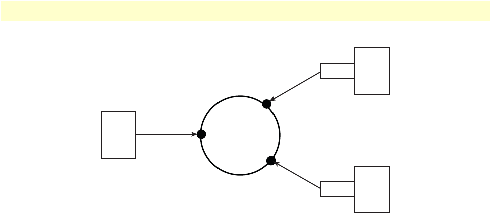
Serial port configuration task list 56
OnSite 2800 Series User Manual 4 • Serial port configuration
Figure 14. IP Context with logical IP interfaces bound to Ethernet port, serial port PVC 1 and PVC 2
The related IP, serial interface and Frame Relay configuration procedure is listed below. Where necessary,
comments are added to the configuration for better understanding.
1. Enter the configuration mode.
2800>enable
2800#configure
…
2. Set up the IP interface configuration first. Be aware that not all of the necessary settings are listed below.
2800(cfg)#context ip router
2800(ctx-ip)[router]#interface external
2800(if-ip)[external]#interface internal
2800(if-ip)[internal]#interface lan
2800(if-ip)[lan]#exit
2800(ctx-ip)[router]#interface internal
2800(if-ip)[internal]#ipaddress 192.168.3.1 255.255.255.0
2800(if-ip)[internal]#interface external
2800(if-ip)[external]#ipaddress 192.168.2.1 255.255.255.0
2800(if-ip)[external]#interface lan
2800(if-ip)[lan]#ipaddress 192.168.1.1 255.255.255.0
…
3. Configure the serial interface settings.
2800(cfg)#port serial 0 0
2800(prt-ser)[0/0]#shutdown
2800(prt-ser)[0/0]#encapsulation framerelay
…
4. Configure the Frame Relay. You must thus change to the Frame Relay configuration mode. Use the ser-
vice-policy profile defined above to give voice priority over data.
2800(prt-ser)[0/0]#framerelay
2800(frm-rel)[0/0]#lmi-type ansi
2800(frm-rel)[0/0]#keepalive 20
…
Context
IP
“router”
192.168.2.1
IP interface
external PVC 1
Port
Serial
0 0
192.168.3.1
Port
Ethernet
0 0
IP interface
lan
192.168.1.1
PVC 2
Port
Serial
0 0
IP interface
external

Serial port configuration task list 57
OnSite 2800 Series User Manual 4 • Serial port configuration
5. Configure the introduced PVCs.
2800(frm-rel)[0/0]#pvc 1
2800(pvc)[1]#encapsulation rfc1490
2800(pvc)[1]#bind interface external router
2800(pvc)[1]#no shutdown
2800(pvc)[1]#pvc 2
2800(pvc)[2]#encapsulation rfc1490
2800(pvc)[2]#bind interface internal router
2800(pvc)[2]#no shutdown
…
6. Check that the Frame Relay settings are correct.
2800(frm-rel)[0/0]#show framerelay
Framerelay Configuration:
Port LMI-Type Keepalive Fragmentation
----------------------------------------------------------
serial 0 0 0 ansi 20 disabled
PVC Configuration:
Port DLCI State Fragment Encaps Binding
--------------------------------------------------------------
serial 0 0 0 1 open disabled rfc1490 external@router
serial 0 0 0 2 open disabled rfc1490 internal@router

58
Chapter 5 T1/E1 port configuration
Chapter contents
Introduction..........................................................................................................................................................59
T1/E1 port configuration task list..........................................................................................................................59
Enable/Disable T1/E1 port .............................................................................................................................59
Configuring T1/E1 port-type ..........................................................................................................................60
Configuring T1/E1 clock-mode ......................................................................................................................60
Configuring T1/E1 line-code ..........................................................................................................................60
Configuring T1/E1 framing ............................................................................................................................61
Configuring T1/E1 line-build-out (T1 only) ..................................................................................................61
Configuring T1/E1 used-connector (E1 only) .................................................................................................61
Configuring T1/E1 application mode .............................................................................................................62
Configuring T1/E1 LOS threshold .................................................................................................................62
Configuring T1/E1 encapsulation ...................................................................................................................62
Create a Channel-Group .................................................................................................................................62
Configuring Channel-Group Timeslots ..........................................................................................................63
Configuring Channel-Group Encapsulation ...................................................................................................63
Entering HDLC Configuration Mode ............................................................................................................63
Configuring HDLC CRC-Type .....................................................................................................................64
Configuring HDLC Encapsulation .................................................................................................................64
T1/E1 Configuration Examples ......................................................................................................................64
Example 1: Frame Relay without a channel-group ....................................................................................65
Example 2: Framerelay with a channel-group ............................................................................................66
Example 3: PPP without a channel-group .................................................................................................66
Example 4: PPP with a channel-group ......................................................................................................66

Introduction 59
OnSite 2800 Series User Manual 5 • T1/E1 port configuration
Introduction
This chapter provides an overview of the T1/E1 WAN port, their characteristics and describes the configura-
tion tasks.
The model 2803 has a T1/E1 WAN port on the rear panel of the unit. The T1 version (Model 2803T) has an
RJ-48C connector, and the E1 version (Model 2803K) offers the user connectivity via either the RJ-48C or
dual coaxial connectors. Both models can be configured for T1 or E1 operation.
The configurable parameters for the T1/E1 port are type (T1 or E1), clock mode (or source) (master or slave),
line code (AMI, HDB3, or B8ZS), framing (CRC-4, ESF, or unframed), line-build-out (for T1 only) and
encapsulation (channelized or HDLC).
A further feature is the creation and configuration of channel-groups.
T1/E1 port configuration task list
This section describes the configuration tasks for the T1/E1 port.
•Enable/Disable T1/E1 port
•Configuring the T1/E1 port type
•Configuring T1/E1 clock mode
•Configuring T1/E1 line code
•Configuring T1/E1 framing
•Configuring T1 line build out (LBO) (T1 only)
•Configuring E1 impedance/connector
•Configuring T1/E1 application mode
•Configuring T1/E1 LOS threshold
•Configuring T1/E1 encapsulation
•Create a Channel-Group
•Configuring channel-group timeslots
•Configuring channel-group encapsulation
•Entering HDLC configuration mode
•Configuration HDLC CRC-type
•Configuring HDLC encapsulation
Enable/Disable T1/E1 port
By default, the T1/E1 port is disabled. The following command is used for enabling or disabling it.

T1/E1 port configuration task list 60
OnSite 2800 Series User Manual 5 • T1/E1 port configuration
Mode: port e1t1 <slot> <port>
Configuring T1/E1 port-type
The T1/E1 Port can either work in T1 or in E1 (G.704) mode. This mode can be changed dynamically as long
as no encapsulation or encapsulation ‘hdlc’ is set. Be aware that changing the port-type also resets the framing
and linecode parameters to the default values of the new port-type. If port-type change is not allowed due to
current configuration, an error message will be issued.
Mode: port e1t1 <slot> <port>
Configuring T1/E1 clock-mode
The T1/E1 Port can either work in clock-master or in clock-slave mode. This setting defines the clock depen-
dency of the internal data processing. In clock-master mode the internal data processing is running on an inde-
pendent clock source. In clock-slave mode the clock source for internal data processing is recovered from the
receive line interface. Be aware that always a port-pair of clock-master and clock-slave are connected together.
In the other case the data transmission will fail due to bit failures.
Mode: port e1t1 <slot> <port>
Configuring T1/E1 line-code
Three different line codes can be selected on the T1/E1 port whereas only ‘ami’ is standardized for E1 and T1.
If the port is running in E1 mode, ‘hdb3’ is also configurable and in T1 mode ‘b8zs’. If a linecode will be
selected that is not standardized for the current port mode, an error message will be advised.
Mode: port e1t1 <slot> <port>
Step Command Purpose
1 [name] (prt-e1t1)[slot/port]# [no]
shutdown
Enable/Disable the T1/E1 port.
Default: shutdown (which is disabled)
Step Command Purpose
1 [name] (prt-e1t1)[slot/port]# port-type
{e1 | t1}
Changes operation mode of the port.
Default: e1
Step Command Purpose
1 [name] (prt-e1t1)[slot/port]# clock {mas-
ter | slave}
Configures the clock-mode of the port.
Default: master
Step Command Purpose
1 [name] (prt-e1t1)[slot/port]# linecode
{ami | b8zs | hdb3}
Configures the line-code of the port.
Default for e1: hdb3
Default for t1: b8zs

T1/E1 port configuration task list 61
OnSite 2800 Series User Manual 5 • T1/E1 port configuration
Configuring T1/E1 framing
Four framing formats are available for selection on the T1/E1 port. Unframed can only be used if the encapsu-
lation is set for hdlc. All other currently available upper layer (encapsulation) protocols do not run in unframed
mode, but in one of the framed modes.
In structured mode, E1 can be configured for crc4 or non-crc4. T1 has a single framed option, esf.
The advantage of the unframed mode (obviously with hdlc encapsulation) is the utilization of the whole link
speed for user data transmission, 2.048MBit/s for E1 and 1.544MBit/s for T1. However note that HDLC has
its own overhead which decreases the actual data rate.
Mode: port e1t1 <slot> <port>
Configuring T1/E1 line-build-out (T1 only)
The line build out configuration is used in long haul applications to prevent cross talk in the far end device.
Mode: port e1t1 <slot> <port>
Configuring T1/E1 used-connector (E1 only)
The E1 WAN port provides several line interface connector types, RJ-48C and dual coaxial BNC connectors.
This command specifies which one is currently in use. Though the signal is always on all available connectors,
the internal impedance matching must be selected for the appropriate interface (RJ-48C = 120 Ohm; BNC =
75 Ohm).
Mode: port e1t1 <slot> <port>
Step Command Purpose
1 [name] (prt-e1t1)[slot/port]# framing
{crc4 | non-crc4 | esf | unframed}
Configures the framing of the port.
E1 mode formats are: crc4, non-crc4, unframed.
T1 mode formats are: esf, unframed.
Default for e1: crc4
Default for t1: esf
Step Command Purpose
1 [name] (prt-e1t1)[slot/port]# line-build-
out {0 | -7.5 | -15 | -22.5}
Specifies the pulse attenuation in dB on the line inter-
face. Default for t1: 0 dB
Step Command Purpose
1 [name] (prt-e1t1)[slot/port]# used-con-
nector {bnc | rj45}
Specifies the currently used connector.
Default for e1: rj45

T1/E1 port configuration task list 62
OnSite 2800 Series User Manual 5 • T1/E1 port configuration
Configuring T1/E1 application mode
The T1/E1 port can be configured to work in either short-haul or in long-haul mode. Short-haul is the default
application and should be used for transmission distances up to 180m/600ft. For transmission distances up to
1800m/6000ft, select the long-haul application.
Mode: port e1t1 <slot> <port>
Configuring T1/E1 LOS threshold
This command takes effect only if the T1/E1 port is configured for long-haul applications. It specifies the sen-
sitivity for Loss Of Signal threshold. A signal suffers more attenuation over long distances than over short dis-
tances. Therefore the LOS-Threshold must be set higher for longer transmission distances. This command has
a default value of -46dB what should be enough for distances up to 1600 m/5250 ft.
Mode: port e1t1 <slot> <port>
Configuring T1/E1 encapsulation
Only ‘hdlc’ encapsulation is available on a T1/E1 port. Once encapsulation is configured as ‘hdlc,’ the ‘hdlc’
submode can be entered for selecting the next encapsulation type like ppp or framerelay. Depending on the
port-type, the encapsulation ‘hdlc’ selects automatically all timeslots of the port for data transmission (1-31 for
e1 and 1-24 for t1).
It is also possible to use the port in channelized mode. In “channelized” mode, the user selects less than the
total number of timeslots for the channel (1-31 for E1, 1 – 24 for T1) is able to configure single or multiple
timeslots for data transmission. To use this feature the encapsulation must be configured for ‘channelized;’
afterwards the channel-group command is used to create the channel-group. In the channel-group configura-
tion mode, the user selects the specific timeslots, and the encapsulation ‘hdlc’ will be available again. Once the
encapsulation of a T1/E1 port is set to ‘channelized’ it is not possible to change the port-type again or to use
the ‘unframed’ framing format.
Mode: port e1t1 <slot> <port>
Create a Channel-Group
If the desired encapsulated channel uses only selected time slots (not the entire T1/E1), then it is necessary to
set up a channel-group. To create a channel-group, set the T1/E1 port’s encapsulation to channelized. (See sec-
Step Command Purpose
1 [name] (prt-e1t1)[slot/port]#application
{long-haul | short-haul}
Specifies the e1/t1 application mode
Default: short-haul
Step Command Purpose
1[ name] (prt-e1t1)[slot/port]#los-thresh-
old {-4dB | -6dB | -8dB … -46dB | -
48dB}
Specifies Loss Of Signal Threshold
Default: -46dB
Step Command Purpose
1 [name] (prt-e1t1)[slot/port]#[no] encapsu-
lation {channelized | hdlc}
Specifies the encapsulation type of the T1/E1 port.
Default: no encapsulation

T1/E1 port configuration task list 63
OnSite 2800 Series User Manual 5 • T1/E1 port configuration
tion “Configuring T1/E1 encapsulation”.) On creating a new channel-group the channel-group configuration
mode is immediately entered. To remove an existing channel-group the ‘no’ form of the command has to
be used.
Mode: port e1t1 <slot> <port>
Configuring Channel-Group Timeslots
The ‘timeslots’ command configures an arbitrary sequence of timeslots for use in data transmission. The syntax
of the command accepts comma-separated groups of timeslots. A group can be a single timeslot or a range of
timeslots. The channel-group timeslots do not have to be contiguous. The ‘no’ form of the command releases
all previously selected timeslots.
Example:
>timeslots 1,4,6 Selects three timeslots (1, 4 an 6)
>timeslots 1,4-6 Selects four timeslots (1, 4, 5 and 6)
>timeslots 1-3,4-6 Selects six timeslots (1, 2, 3, 4, 5 and 6)
Mode: channel-group group-name
Configuring Channel-Group Encapsulation
In the channel-group configuration mode only the encapsulation type ‘hdlc’ is available. For more details see ,
“Configuring T1/E1 encapsulation” on page 62.
Mode: channel-group group-name
Entering HDLC Configuration Mode
The hdlc configuration mode can be entered either from the “port T1/E1” configuration mode or from the
“channel-group” configuration mode. If you cannot enter the hdlc mode, it may be due to an invalid or incom-
plete configuration, and an error message will be issued. In “port T1/E1” configuration mode, you only need
to set the encapsulation for ‘hdlc’ in order to enter the hdlc configuration mode. In “channel-group” configu-
Step Command Purpose
1 [name] (prt-e1t1)[slot/port]#[no] channel-
group group-name
Enters the channel-group configuration mode of
group-name. If the group does not yet exist a new
one will be created. The ‘no’ form of the command
removes an existing channel-group.
Step Command Purpose
1 [name] (ch-grp)[group-name]#[no]
timeslots timeslots
Selects the timeslots to be used.
Default: no timeslots
Step Command Purpose
1 [name] (ch-grp)[group-name]#[no] encap-
sulation hdlc
Specifies the encapsulation type of the channel-
group. Default: no encapsulation

T1/E1 port configuration task list 64
OnSite 2800 Series User Manual 5 • T1/E1 port configuration
ration mode the encapsulation must be set to ‘hdlc’ as well followed by configuring at least one timeslot per the
‘timeslots’ command.
Mode: port e1t1 <slot> <port>
Mode: channel-group <group>
Configuring HDLC CRC-Type
This command specifies the length of the checksum for calculating the CRC of the hdlc-frame. It can be either
a 16-bit or a 32-bit checksum.
Mode: hdlc
Configuring HDLC Encapsulation
The hdlc encapsulation command specifies what kinds of upper layer data are contained in the hdlc frames.
Two encapsulation types are available, framerelay and ppp. Once the hdlc configuration mode has been
entered, the procedure for setting up framerelay or ppp is exactly the same as for an X.21/V.35 serial port. For
that reason, see 4, “Serial port configuration” on page 44 for details about frame relay configuration and the
“OnSite Software Configuration Guide” for details about PPP configuration.
Mode: hdlc
T1/E1 Configuration Examples
Here is a group of four configuration examples.
•Example 1: Frame Relay without a channel-group
•Example 2: Frame Relay with a channel-group
•Example 3: PPP without a channel-group
•Example 4: PPP with a channel-group
Step Command Purpose
1 [name] (prt-e1t1)[slot/port]# hdlc Entering the hdlc configuration mode
Step Command Purpose
1 [name] (ch-grp)[group-name]#hdlc Entering the hdlc configuration mode
Step Command Purpose
1 [name] (hdlc)#crc-type {crc16 | crc32} Selects the checksum-type to be used.
Default: crc16
Step Command Purpose
1 [name] (hdlc)#encapsulation {framere-
lay | ppp}
Specifies the encapsulation type of hdlc.
Default: no encapsulation

T1/E1 port configuration task list 65
OnSite 2800 Series User Manual 5 • T1/E1 port configuration
Example 1: Frame Relay without a channel-group
port e1t1 0 0
port-type e1
framing crc4
encapsulation hdlc
hdlc
encapsulation framerelay
framerelay
lmi-type itu
pvc 100
encapsulation rfc1490
bind interface pvc100 router
no shutdown
port e1t1 0 0
no shutdown

T1/E1 port configuration task list 66
OnSite 2800 Series User Manual 5 • T1/E1 port configuration
Example 2: Framerelay with a channel-group
port e1t1 0 0
port-type e1
framing crc4
encapsulation channelized
channel-group myGroup
timeslots 13-17
encapsulation hdlc
hdlc
encapsulation framerelay
framerelay
lmi-type itu
pvc 100
encapsulation rfc1490
bind interface pvc100 router
no shutdown
port e1t1 0 0
no shutdown
Example 3: PPP without a channel-group
port e1t1 0 0
port-type e1
framing crc4
encapsulation hdlc
hdlc
encapsulation ppp
bind interface myPPP router
port e1t1 0 0
no shutdown
Example 4: PPP with a channel-group
port e1t1 0 0
port-type e1
framing crc4
encapsulation channelized
channel-group yourGroup
timeslots 1,9,16,23
encapsulation hdlc
hdlc
encapsulation ppp
bind interface myPPP router
port e1t1 0 0
no shutdown

67
Chapter 6 VPN configuration
Chapter contents
Introduction..........................................................................................................................................................68
Authentication ................................................................................................................................................68
Encryption ......................................................................................................................................................68
Transport and tunnel modes ...........................................................................................................................69
VPN configuration task list ...................................................................................................................................69
Creating an IPsec transformation profile .........................................................................................................69
Creating an IPsec policy profile .......................................................................................................................70
Creating/modifying an outgoing ACL profile for IPsec ...................................................................................72
Configuration of an IP interface and the IP router for IPsec ............................................................................73
Displaying IPsec configuration information ....................................................................................................73
Debugging IPsec .............................................................................................................................................74
Sample configurations ...........................................................................................................................................75
IPsec tunnel, DES encryption .........................................................................................................................75
OnSite configuration .................................................................................................................................75
Cisco router configuration ........................................................................................................................76
IPsec tunnel, AES encryption at 256 bit key length, AH authentication with HMAC-SHA1-96 ....................76
OnSite configuration .................................................................................................................................76
Cisco router configuration ........................................................................................................................77
IPsec tunnel, 3DES encryption at 192 bit key length, ESP authentication with HMAC-MD5-96 ..................77
OnSite configuration .................................................................................................................................77
Cisco router configuration ........................................................................................................................77

Introduction 68
OnSite 2800 Series User Manual 6 • VPN configuration
Introduction
This chapter describes how to configure the VPN connections between two OnSite routers or between an
OnSite and a third-party device.
A virtual private network (VPN) is a private data network that uses the public telecommunications infrastruc-
ture, maintaining privacy through the use of a tunneling protocol and security procedures.
There are different technologies to implement a VPN. OnSite applies the internet protocol security (IPsec)
Architecture (see RFC 2401). The following sections describe the main building blocks of the IPsec architec-
ture as implemented in OnSite router.
Authentication
Authentication verifies the integrity of data stream and ensures that it is not tampered with while in transit. It
also provides confirmation about data stream origin.
Two authentication protocols are available:
•Authentication header (AH): protects the IP payload, the IP header, and the authentication header itself
•Encapsulating security payload (ESP): protects the IP payload and the ESP header and trailer, but not the
IP header
Two algorithms perform the authentication:
•HMAC-MD5-96: is a combination of the keyed-hashing for message authentication (HMAC) and the message
digest version 5 (MD5) hash algorithm. It requires an authenticator of 128-bit length and calculates a hash
of 96 bits over the packet to be protected (see RFC 2403).
•HMAC-SHA1-96: is a combination of the (HMAC) and the secure hash algorithm version 1 (SHA1). It
requires an authenticator of 160 bit length and calculates a hash of 96 bits over the packet to be protected
(see RFC 2404).
Encryption
Encryption protects the data in transit from unauthorized access. Encapsulating security payload (ESP) is the
protocol to transport encrypted IP packets over IP (see RFC 2406).
The following encryption algorithms are available:
The single DES algorithm no longer offers adequate security because of its short key length (a minimum key
length 100 bits is recommended). The AES algorithm is very efficient and allows the fastest encryption. AES
with a key length of 128 bits is therefore the recommended algorithm.
Key Length [Bit] RFC
DES-CBC (Data Encryption Standard - Cipher Block Chaining) 56 2405
3DES-CBC (Triple Data Encryption Standard - Cipher Block Chaining) 128 or 192
a
a. The 3DES algorithm uses only 112 out of the 128 Bit or 168 out of the 192 Bit as key information. Cisco
only supports 192 Bit keys with 3DES.
1851
AES-CBC (Advanced Encryption Standard - Cipher Block Chaining) 128, 192, or 256 3268

VPN configuration task list 69
OnSite 2800 Series User Manual 6 • VPN configuration
Transport and tunnel modes
The mode determines the payload of the ESP packet and hence the application:
•Transport mode: Encapsulates only the payload of the original IP packet, but not its header, so the IPsec
peers must be at the endpoints of the communications link.
•A secure connection between two hosts is the application of the transport mode.
•Tunnel mode: Encapsulates the payload and the header of the original IP packet. The IPsec peers can be
(edge) routers that are not at the endpoints of the communications link.
A secure connection of the two (private) LANs, a ‘tunnel’, is the application of the tunnel mode.
VPN configuration task list
To configure a VPN connection, perform the following tasks:
•Creating an IPsec transformation profile
•Creating an IPsec policy profile
•Creating/modifying an outgoing ACL profile for IPsec
•Configuration of an IP Interface and the IP router for IPsec
•Displaying IPsec configuration information
•Debugging IPsec
Creating an IPsec transformation profile
The IPsec transformation profile defines which authentication and/or encryption protocols, which authentica-
tion and/or encryption algorithms shall be applied.
Procedure: To create an IPsec transformation profile
Mode: Configure
mac-sha1-96 }Enables authentication and defines the authentication protocol and the hash algorithm
Use no in front of the above commands to delete a profile or a configuration entry.
Example: Create an IPsec transformation profile
The following example defines a profile for AES-encryption at a key length of 128.
2800(cfg)#profile ipsec-transform AES_128
2800(pf-ipstr)[AES_128]#esp-encryption aes-cbc 128
Step Command Purpose
1node(cfg)#profile ipsec-transform name Creates the IPsec transformation profile name
2
optional
node(pf-ipstr)[name]#esp-encryption {
aes-cbc | des-cbc | 3des-cbc } [key-length]
Enables encryption and defines the encryp-
tion algorithm and the key length
3
optional
node(pf-ipstr)[name]#{ ah-authentication
| esp-authentication } {hmac-md5-96 |
hmac-sha1-96 }
Enables authentication and defines the
authentication protocol and the hash algo-
rithm

VPN configuration task list 70
OnSite 2800 Series User Manual 6 • VPN configuration
Creating an IPsec policy profile
The IPsec policy profile supplies the keys for the encryption and/or the authenticators for the authentication,
the security parameters indexes (SPIs), and IP address of the peer of the secured communication. Furthermore,
the profile defines which IPsec transformation profile to apply and whether transport or tunnel mode shall be
most effective.
The SPI identifies a secured communication channel. The IPsec component needs the SPI to select the suitable
key or authenticator. Inbound and outbound channels can have the same SPI, but the channels in the same
direction—inbound or outbound—must have unique SPIs. The SPI is not encrypted and can be monitored.
Procedure: To create an IPsec policy profile

VPN configuration task list 71
OnSite 2800 Series User Manual 6 • VPN configuration
Mode: Configure
Use no in front of the above commands to delete a profile or a configuration entry.
Step Command Purpose
1node(cfg)#profile ipsec-policy-man-
ual name
Creates the IPsec policy profile name
2node(pf-ipstr)[name]#use profile
ipsec-transform name
Selects the IPsec transformation profile to be
applied
3
optional
node(pf-ipstr)[name]#session-key
{ inbound | outbound }
{ ah-aauthentication | esp-
authentication | esp-encryption } key
Sets a key for encryption or an authenticator for
authentication, either for inbound or outbound
direction. The key shall consist of hexadecimal
digits (0..9, A..F); one digit holds 4 Bit of key
information.
The key setting must match definitions in the
respective IPsec transformation profile. In particu-
lar, the length of the key or authenticator must
match the implicit (see section
“Authentication”
on page 68 and
“Encryption”
on page 68) or
explicit specification.
Keys must be available for inbound and out-
bound directions. They can be different for the
two directions. Make sure that the inbound key
of one peer matches the outbound key of the
other peer.
4node(pf-ipstr)[name]#spi
{ inbound | outbound } { ah | esp } spi
Sets the SPI for encryption (esp) or authentication
(ah), either for inbound or outbound direction.
The SPI shall be a decimal figure in the range
1..2
32
–1.
SPIs must be available for encryption and/or
authentication as specified in the respective IPsec
transformation profile.
SPIs must be available for inbound and outbound
directions. They can be identical for the two
directions but must be unique in one direction.
Make sure that the inbound SPI of one peer
matches the outbound SPI of the other peer.
5node(pf-ipstr)[name]#peer ip-address Sets the IP address of the peer
Note The peers of the secured
communication must have
static IP address. DNS reso-
lution is not available yet.
6node(pf-ipstr)[name]#mode
{ tunnel | transport }
Selects tunnel or transport mode

VPN configuration task list 72
OnSite 2800 Series User Manual 6 • VPN configuration
Example: Create an IPsec policy profile
The following example defines a profile for AES-encryption at a key length of 128.
2800(cfg)#profile ipsec-policy-manual ToBurg
2800(pf-ipsma)[ToBurg]#use profile ipsec-transform AES_128
2800(pf-ipsma)[ToBurg]#session-key inbound esp-encryption
1234567890ABCDEF1234567890ABCDEF
2800(pf-ipsma)[ToBurg]#session-key outbound esp-encryption
FEDCBA0987654321FEDCBA0987654321
2800(pf-ipsma)[ToBurg]#spi inbound esp 1111
2800(pf-ipsma)[ToBurg]#spi outbound esp 2222
2800(pf-ipsma)[ToBurg]#peer 200.200.200.1
2800(pf-ipsma)[ToBurg]#mode tunnel
Creating/modifying an outgoing ACL profile for IPsec
An access control list (ACL) profile in the outgoing direction selects which outgoing traffic to encrypt and/or
authenticate, and which IPsec policy profile to use. IPsec does not require an incoming ACL.
Note
Outgoing and incoming IPsec traffic passes an ACL (if available)
twice, once before and once after encryption/authentication. So the
respective ACLs must permit the encrypted/authenticated and the
plain traffic.
For detailed information on how to set-up ACL rules, see chapter 7, “Access control list configuration” on
page 79.
Procedure: To create/modify an outgoing ACL profile for IPsec
Mode: Configure
Note
New entries are appended at the end of an ACL. Since the position in
the list is relevant, you might need to delete the ACL and rewrite it
completely.
Example: Create/modify an ACL profile for IPsec
The following example configures an outgoing ACL profile that interconnects the two private networks
192.168.1/24 and 172.16/16.
2800(cfg)#profile acl VPN_Out
2800(pf-acl)[VPN_Out]#permit ip 192.168.1.0 0.0.0.255 172.16.0.0 0.0.255.255 ipsec-
policy ToBurg
2800(pf-acl)[VPN_Out]#permit ip any any
Step Command Purpose
1node(cfg)#profile acl name Creates or enters the ACL profile name
2node(pf-ipstr)[name]#permit ...
[ ipsec-policy name ]
The expression ‘ipsec-policy name’ appended to a
permit ACL rule activates the IPsec policy profile
name to encrypt/authenticate the traffic identified
by this rule.

VPN configuration task list 73
OnSite 2800 Series User Manual 6 • VPN configuration
Configuration of an IP interface and the IP router for IPsec
The IP interface that provides connectivity to the IPsec peer, must now activate the outgoing ACL profile con-
figured in the previous section. Furthermore, the IP router must have a route for the remote network that
points to the respective IP interface.
Procedure: To activate the outgoing ACL profile and to establish the necessary route
Mode: Configure
Example: Activate outgoing ACL and establish route
The following example configures an outgoing ACL profile that interconnects the two private networks
192.168.1/24 and 172.16/16.
2800(cfg)#context ip router
2800(ctx-ip)[router]#interface WAN
2800(if-ip)[WAN]#use profile acl VPN_Out out
2800(if-ip)[WAN]#context ip router
2800(ctx-ip)[router]#route 172.16.0.0 255.255.0.0 WAN 0
Displaying IPsec configuration information
This section shows how to display and verify the IPsec configuration information.
Procedure: To display IPsec configuration information
Mode: Configure
Step Command Purpose
1node(cfg)#context ip router Enter IP context
2node(ctx-ip)[router]#interface if-name Create/enter the IP interface if-name
3node(if-ip)[if-name]# use profile acl
name out
Activate the outgoing ACL profile name
4node(if-ip)[if-name]#context ip router Enter IP context
5
optional
node(ctx-ip)[router]#route remote-net-
work-address remote-network-mask if-name 0
Creates a route for the remote network that
points the above IP interface if-name
You can omit this setting if the default route
already points to this IP interface or to a next hub
reachable via this IP interface, and if there is no
other route.
Make also sure that the IP router knows how to
reach the peer of the secured communication.
Usually, a default route does this job.
Step Command Purpose
1
optional
node(cfg)#show profile ipsec-trans-
form
Displays all IPsec transformation profiles
2
optional
node(cfg)#show profile ipsec-policy-
manual
Displays all IPsec policy profiles

VPN configuration task list 74
OnSite 2800 Series User Manual 6 • VPN configuration
Example: Display IPsec transformation profiles
2800(cfg)#show profile ipsec-transform
IPSEC transform profiles:
Name: AES_128
ESP Encryption: AES-CBC, Key length: 128
Example: Display IPsec policy profiles
2800(cfg)#show profile ipsec-policy-manual
Manually keyed IPsec policy profiles:
Name: ToBurg, Peer: 200.200.200.1, Mode: tunnel, transform-profile: AES_128
ESP SPI Inbound: 1111, Outbound: 2222
ESP Encryption Key Inbound: 1234567890ABCDEF1234567890ABCDEF
ESP Encryption Key Outbound: FEDCBA0987654321FEDCBA0987654321
Debugging IPsec
A debug monitor and an additional show command are at your disposal to debug IPsec problems.
Procedure: To debug IPsec connections
Mode: Configure
Example: IPsec Debug Output
2800(cfg)#debug ipsec
IPSEC monitor on
23:11:04 ipsec > Could not find security association for inbound ESP packet.
SPI:1201
Example: Display IPsec Security Associations
2800(cfg)#show ipsec security-associations
Active security associations:
Dir Type Policy Mode Udp-Encapsulation
Peer SPI AH SPI ESP AH ESP-Auth ESP-Enc
Bytes (processed/lifetime) Seconds (age/lifetime)
Step Command Purpose
1node(cfg)#debug ipsec Enables IPsec debug monitor
2
optional
node(cfg)#show ipsec security-associ-
ations
Summarizes the configuration information of all
IPsec connections. If an IPsec connection does
not show up, then one or more parameters are
missing in the respective Policy Profile.
The information ‘Bytes (processed)’ supports
debugging because it indicates whether IPsec
packets depart from (‘OUT’) or arrive at (‘IN’) the
OnSite router.

Sample configurations 75
OnSite 2800 Series User Manual 6 • VPN configuration
IN MANUAL ToBurg Tunnel no
200.200.200.1 - 1111 - - AES-CBC 128
3622/unlimited 19047/unlimited
OUT MANUAL ToBurg Tunnel no
200.200.200.1 - 2222 - - AES-CBC 128
2857/unlimited 19047/unlimited
Sample configurations
The following sample configurations establish IPsec connections between an OnSite and a Cisco router. To
interconnect two OnSite routers instead, derive the configuration for the second OnSite by doing the follow-
ing modifications:
•Swap ‘inbound’ and ‘outbound’ settings
•Adjust the ‘peer’ setting
•Swap the private networks in the ACL profiles
•Adjust the IP addresses of the LAN and WAN interfaces
•Adjust the route for the remote network
IPsec tunnel, DES encryption
OnSite configuration
profile ipsec-transform DES
esp-encryption des-cbc 64
profile ipsec-policy-manual VPN_DES
use profile ipsec-transform DES
session-key inbound esp-encryption 1234567890ABCDEF
session-key outbound esp-encryption FEDCBA0987654321
spi inbound esp 1111
spi outbound esp 2222
peer 200.200.200.1
mode tunnel
profile acl VPN_Out
permit ip 192.168.1.0 0.0.0.255 172.16.0.0 0.0.255.255 ipsec-policy VPN_DES
permit ip any any
profile acl VPN_In
permit esp any any
permit ah any any
permit ip 172.16.0.0 0.0.255.255 192.168.1.0 0.0.0.255
deny ip any any
context ip router
interface LAN
ipaddress 192.168.1.1 255.255.255.0
interface WAN

Sample configurations 76
OnSite 2800 Series User Manual 6 • VPN configuration
ipaddress 200.200.200.2 255.255.255.252
use profile acl VPN_In in
use profile acl VPN_Out out
context ip router
route 0.0.0.0 0.0.0.0 200.200.200.1 0
route 172.16.0.0 255.255.0.0 WAN 0
Cisco router configuration
crypto ipsec transform-set DES esp-des
!
crypto map VPN_DES local-address FastEthernet0/1
crypto map VPN_DES 10 ipsec-manual
set peer 200.200.200.2
set session-key inbound esp 2222 cipher FEDCBA0987654321
set session-key outbound esp 1111 cipher 1234567890ABCDEF
set transform-set DES
match address 110
!
access-list 110 permit ip 172.16.0.0 0.0.255.255 192.168.1.0 0.0.0.255
!
interface FastEthernet0/0
ip address 172.16.1.1 255.255.0.0
!
interface FastEthernet0/1
ip address 200.200.200.1 255.255.255.252
crypto map VPN_DES
!
ip route 192.168.1.0 255.255.255.0 FastEthernet0/1
IPsec tunnel, AES
encryption
at 256 bit key length, AH authentication with HMAC-
SHA1-96
OnSite configuration
profile ipsec-transform AES_SHA1
esp-encryption aes-cbc 256
ah-authentication hmac-sha1-96
profile ipsec-policy-manual VPN_AES_SHA1
use profile ipsec-transform AES_SHA1
session-key inbound ah-authentication 1234567890ABCDEF1234567890ABCDEF12345678
session-key outbound ah-authentication FEDCBA0987654321FEDCBA0987654321FEDCBA09
session-key inbound esp-encryption
1234567890ABCDEF1234567890ABCDEF1234567890ABCDEF1234567890ABCDEF
session-key outbound esp-encryption
FEDCBA0987654321FEDCBA0987654321FEDCBA0987654321FEDCBA0987654321
spi inbound ah 3333
spi outbound ah 4444
spi inbound esp 5555
spi outbound esp 6666
peer 200.200.200.1
mode tunnel
...

Sample configurations 77
OnSite 2800 Series User Manual 6 • VPN configuration
Rest of the configuration, see above, just change the name of the IPsec policy pro-
file in the ACL profile ‘VPN_Out’
Cisco router configuration
crypto ipsec transform-set AES_SHA1 ah-sha-hmac esp-aes 256
!
crypto map VPN_AES_SHA1 local-address FastEthernet0/1
crypto map VPN_AES_SHA1 10 ipsec-manual
set peer 200.200.200.2
set session-key inbound esp 6666 cipher
FEDCBA0987654321FEDCBA0987654321FEDCBA0987654321FEDCBA0987654321
set session-key outbound esp 5555 cipher
1234567890ABCDEF1234567890ABCDEF1234567890ABCDEF1234567890ABCDEF
set session-key inbound ah 4444 FEDCBA0987654321FEDCBA0987654321FEDCBA09
set session-key outbound ah 3333 1234567890ABCDEF1234567890ABCDEF12345678
set transform-set AES_SHA1
match address 110
!
...
For the remainder of the configuration (see above), just change the name of the IPsec policy profile in the ACL
profile VPN_Out
IPsec tunnel, 3DES encryption at 192 bit key length, ESP authentication with
HMAC-MD5-96
OnSite configuration
profile ipsec-transform TDES_MD5
esp-encryption 3des-cbc 192
esp-authentication hmac-md5-96
profile ipsec-policy-manual VPN_TDES_MD5
use profile ipsec-transform TDES_MD5
session-key inbound esp-authentication 1234567890ABCDEF1234567890ABCDEF
session-key outbound esp-authentication FEDCBA0987654321FEDCBA0987654321
session-key inbound esp-encryption
1234567890ABCDEF1234567890ABCDEF1234567890ABCDEF
session-key outbound esp-encryption
FEDCBA0987654321FEDCBA0987654321FEDCBA0987654321
spi inbound esp 7777
spi outbound esp 8888
peer 200.200.200.1
mode tunnel
...
For the remainder of the configuration (see above), just change the name of the IPsec policy profile in the ACL
profile VPN_Out
Cisco router configuration
crypto ipsec transform-set 3DES_MD5 esp-3des esp-md5-hmac
!
crypto map VPN_3DES_MD5 local-address FastEthernet0/1
crypto map VPN_3DES_MD5 10 ipsec-manual
set peer 200.200.200.2

Sample configurations 78
OnSite 2800 Series User Manual 6 • VPN configuration
set session-key inbound esp 8888 cipher
FEDCBA0987654321FEDCBA0987654321FEDCBA0987654321 authenticator
FEDCBA0987654321FEDCBA0987654321
set session-key outbound esp 7777 cipher
1234567890ABCDEF1234567890ABCDEF1234567890ABCDEF authenticator
1234567890ABCDEF1234567890ABCDEF
set transform-set 3DES_MD5
match address 110
!
...
For the remainder of the configuration (see above), just change the name of the IPsec policy profile in the ACL
profile VPN_Out.

79
Chapter 7 Access control list configuration
Chapter contents
Introduction..........................................................................................................................................................80
About access control lists .......................................................................................................................................80
What access lists do .........................................................................................................................................80
Why you should configure access lists .............................................................................................................80
When to configure access lists .........................................................................................................................81
Features of access control lists .........................................................................................................................81
Access control list configuration task list................................................................................................................82
Mapping out the goals of the access control list ...............................................................................................82
Creating an access control list profile and enter configuration mode ...............................................................83
Adding a filter rule to the current access control list profile .............................................................................83
Adding an ICMP filter rule to the current access control list profile ................................................................85
Adding a TCP, UDP or SCTP filter rule to the current access control list profile ...........................................87
Binding and unbinding an access control list profile to an IP interface ............................................................89
Displaying an access control list profile ...........................................................................................................90
Debugging an access control list profile ...........................................................................................................90
Examples ...............................................................................................................................................................92
Denying a specific subnet ................................................................................................................................92

Introduction 80
OnSite 2800 Series User Manual 7 • Access control list configuration
Introduction
This chapter provides an overview of IP Access Control Lists and describes the tasks involved in configuring
them through the OnSite router.
This chapter includes the following sections:
•About access control lists
•Access control list configuration task list (see page 82)
•Examples (see page 92)
About access control lists
This section briefly describes what access lists do, why and when you should configure access lists, and basic
versus advanced access lists.
What access lists do
Access lists filter network traffic by controlling whether routed packets are forwarded, dropped or blocked at
the router's interfaces. Your router examines each packet to determine whether to forward or drop the packet,
based on the criteria you specified within the access lists.
Access list criteria could be the source address of the traffic, the destination address of the traffic, the upper-
layer protocol, or other information.
Note
Sophisticated users can sometimes successfully evade or fool basic
access lists because no authentication is required.
Why you should configure access lists
There are many reasons to configure access lists. For example, you can use access lists to restrict contents of
routing updates, or to provide traffic flow control. But one of the most important reasons to configure access
lists is to provide security for your network, and this is the reason explored in this chapter.
You should use access lists to provide a basic level of security for accessing your network. If you do not configure
access lists on your router, all packets passing through the router could be allowed onto all parts of your network.
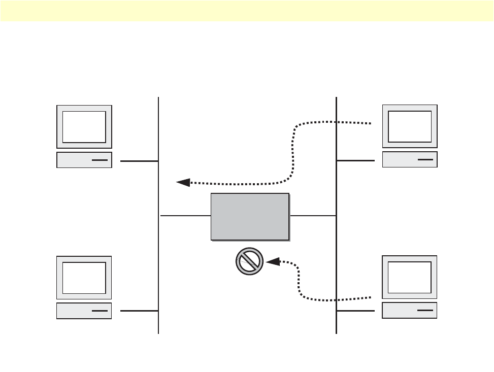
About access control lists 81
OnSite 2800 Series User Manual 7 • Access control list configuration
For example, access lists can allow one host to access a part of your network, and prevent another host from
accessing the same area. In figure 15 host A is allowed to access the Human Resources network and host B is
prevented from accessing the Human Resources network.
Figure 15. Using traffic filters to prevent traffic from being routed to a network
You can also use access lists to decide which types of traffic are forwarded or blocked at the router interfaces.
For example, you can permit e-mail traffic to be routed but at the same time block all Telnet traffic.
When to configure access lists
Access lists should be used in firewall routers, which are often positioned between your internal network and an
external network such as the Internet. You can also use access lists on a router positioned between two parts of
your network, to control traffic entering or exiting a specific part of your internal network.
To provide the security benefits of access lists, you should configure access lists at least on border routers, i.e.
those routers situated at the edges of your networks. This provides a basic buffer from the outside network or
from a less controlled area of your own network into a more sensitive area of your network.
On these routers, you should configure access lists for each network protocol configured on the router interfaces.
You can configure access lists so that inbound traffic or outbound traffic or both are filtered on an interface.
Features of access control lists
The following features apply to all IP access control lists:
•A list may contain multiple entries. The order access of control list entries is significant. Each entry is pro-
cessed in the order it appears in the configuration file. As soon as an entry matches, the corresponding
action is taken and no further processing takes place.
Host A
Host B
Human
Resource
Network
Research &
Development
Network
Node
Node

Access control list configuration task list 82
OnSite 2800 Series User Manual 7 • Access control list configuration
•All access control lists have an implicit deny ip any any at the end. A packet that does not match the criteria
of the first statement is subjected to the criteria of the second statement and so on until the end of the access
control list is reached, at which point the packet is dropped.
•Filter types include IP, Internet Control Message Protocol (ICMP), Transmission Control Protocol (TCP),
User Datagram Protocol (UDP), and Stream Control Transmission Protocol (SCTP).
•An empty access control list is treated as an implicit deny ip any any list.
Note
Two or more administrators should not simultaneously edit the con-
figuration file. This is especially the case with access lists. Doing this
can have unpredictable results.
Once in access control list configuration mode, each command creates a statement in the access control list.
When the access control list is applied, the action performed by each statement is one of the following:
•permit statement causes any packet matching the criteria to be accepted.
•deny statement causes any packet matching the criteria to be dropped.
To delete an entire access control list, enter configuration mode and use the no form of the profile acl com-
mand, naming the access list to be deleted, e.g. no profile acl name. To unbind an access list from the interface
to which it was applied, enter the IP interface mode and use the no form of the access control list command.
Access control list configuration task list
To configure an IP access control list, perform the tasks in the following sections.
•Mapping out the goals of the access control list
•Creating an access control list profile and enter configuration mode (see page 83)
•Adding a filter rule to the current access control list profile (see page 83)
•Adding an ICMP filter rule to the current access control list profile (see page 85)
•Adding a TCP, UDP or SCTP filter rule to the current access control list profile (see page 87)
•Binding and unbinding an access control list profile to an IP interface (see page 89)
•Displaying an access control list profile (see page 90)
•Debugging an access control list profile (see page 90)
Mapping out the goals of the access control list
To create an access control list you must:
•Specify the protocol to be filtered
•Assign a unique name to the access list
•Define packet-filtering criteria
A single access control list can have multiple filtering criteria statements.

Access control list configuration task list 83
OnSite 2800 Series User Manual 7 • Access control list configuration
Before you begin to enter the commands that create and configure the IP access control list, be sure that you
are clear about what you want to achieve with the list. Consider whether it is better to deny specific accesses
and permit all others or to permit specific accesses and deny all others.
Note
Since a single access control list can have multiple filtering criteria
statements, but editing those entries online can be tedious. Therefore,
we recommend editing complex access control lists offline within a
configuration file and downloading the configuration file later via
TFTP to your OnSite device.
Creating an access control list profile and enter configuration mode
This procedure describes how to create an IP access control list and enter access control list configuration mode
Mode: Administrator execution
name is the name by which the access list will be known. Entering this command puts you into access control list
configuration mode where you can enter the individual statements that will make up the access control list.
Use the no form of this command to delete an access control list profile. You cannot delete an access control
list profile if it is currently linked to an interface. When you leave the access control list configuration mode,
the new settings immediately become active.
Example: Create an access control list profile
In the following example the access control list profile named WanRx is created and the shell of the access con-
trol list configuration mode is activated.
2800>enable
2800#configure
2800(cfg)#profile acl WanRx
2800(pf-acl)[WanRx]#
Adding a filter rule to the current access control list profile
The commands permit or deny are used to define an IP filter rule. This procedure describes how to create an
IP access control list entry that permits access
Mode: Profile access control list
This procedure describes how to create an IP access control list entry that denies access
Step Command Purpose
1node(cfg)#profile acl name Creates the access control list profile name and enters the configura-
tion mode for this list
Step Command Purpose
1node(pf-acl)[name]#permit ip {src src-wildcard | any |
host src} {dest dest-wildcard | any | host dest} [cos group]
Creates an IP access of control list
entry that permits access defined
according to the command
options
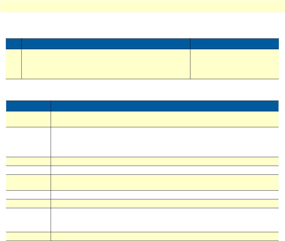
Access control list configuration task list 84
OnSite 2800 Series User Manual 7 • Access control list configuration
Mode: Profile access control list
Where the syntax is:
If you place a deny ip any any rule at the top of an access control list profile, no packets will pass regardless of
the other rules you defined.
Example: Create IP access control list entries
Select the access-list profile named WanRx and create some filter rules for it.
2800(cfg)#profile acl WanRx
2800(pf-acl)[WanRx]#permit ip host 62.1.2.3 host 193.14.2.11 cos Urgent
2800(pf-acl)[WanRx]#permit ip 62.1.2.3 0.0.255.255 host 193.14.2.11
2800(pf-acl)[WanRx]#permit ip 97.123.111.0 0.0.0.255 host 193.14.2.11
2800(pf-acl)[WanRx]#deny ip any any
2800(pf-acl)[WanRx]#exit
2800(cfg)#
Step Command Purpose
1node(pf-acl)[name]#deny ip {src src-wildcard | any | host
src} {dest dest-wildcard | any | host dest} [cos group]
Creates an IP access of control list
entry that denies access defined
according to the command
options
Keyword Meaning
src The source address to be included in the rule. An IP address in dotted-decimal-format,
e.g. 64.231.1.10.
src-wildcard A wildcard for the source address. Expressed in dotted-decimal format this value specifies
which bits are significant for matching. One-bits in the wildcard indicate that the corre-
sponding bits are ignored. An example for a valid wildcard is 0.0.0.255, which speci-
fies a class C network.
any Indicates that IP traffic to or from all IP addresses is to be included in the rule.
host src The address of a single source host.
dest The destination address to be included in the rule. An IP address in dotted-decimal-for-
mat, e.g. 64.231.1.10.
dest-wildcard A wildcard for the destination address. See src-wildcard
host dest The address of a single destination host.
cos Optional. Specifies that packets matched by this rule belong to a certain Class of Service
(CoS). For detailed description of CoS configuration refer to chapter 8,
“Link scheduler
configuration”
on page 93.
group CoS group name.

Access control list configuration task list 85
OnSite 2800 Series User Manual 7 • Access control list configuration
Adding an ICMP filter rule to the current access control list profile
The command permit or deny are used to define an ICMP filter rule. Each ICMP filter rule represents an
ICMP access of control list entry.
This procedure describes how to create an ICMP access control list entry that permits access
Mode: Profile access control list
This procedure describes how to create an ICMP access control list entry that denies access
Mode: Profile access control list
Step Command Purpose
1node(pf-acl)[name]#permit icmp {src src-wildcard | any |
host src} {dest dest-wildcard | any | host dest} [msg name |
type type | type type code code] [cos group]
Creates an ICMP access of con-
trol list entry that permits access
defined according to the com-
mand options
Step Command Purpose
1node(pf-acl)[name]#deny icmp {src src-wildcard |
any | host src} {dest dest-wildcard | any | host dest}
[msg name | type type | type type code code] [cos
group]
Creates an ICMP access of control list
entry that denies access defined accord-
ing to the command options

Access control list configuration task list 86
OnSite 2800 Series User Manual 7 • Access control list configuration
Where the syntax is as following:
If you place a deny ip any any rule at the top of an access-list profile, no packets will pass regardless of the other
rules you defined.
Example: Create ICMP access control list entries
Select the access-list profile named WanRx and create the rules to filter all ICMP echo requests (as used by the
ping command).
2800(cfg)#profile acl WanRx
2800(pf-acl)[WanRx]#deny icmp any any type 8 code 0
2800(pf-acl)[WanRx]#exit
2800(cfg)#
Keyword Meaning
src The source address to be included in the rule. An IP address in dotted-decimal-format, e.g.
64.231.1.10.
src-wildcard A wildcard for the source address. Expressed in dotted-decimal format this value specifies
which bits are significant for matching. One-bits in the wildcard indicate that the corre-
sponding bits are ignored. An example for a valid wildcard is 0.0.0.255, which specifies
a class C network.
any Indicates that IP traffic to or from all IP addresses is to be included in the rule.
host src The address of a single source host.
dest The destination address to be included in the rule. An IP address in dotted-decimal-format,
e.g. 64.231.1.10
dest-wildcard A wildcard for the destination address. See src-wildcard.
host dest The address of a single destination host.
msg name The ICMP message name. The following are valid message names:
administratively-prohibited, alternate-address, conversion-error, dod-host-prohibited, dod-
net-prohibited, echo, echo-reply, general-parameter-problem, host-isolated, host-prece-
dence-unreachable, host-redirect, host-tos-redirect, host-tos-unreachable, host-unknown,
host-unreachable, information-reply, information-request, mask-reply, mask-request, mobile-
redirect, net-redirect, net-tos-redirect, net-tos-unreachable, net-unreachable, network-
unknown, no-room-for-option, option-missing, packet-too-big, parameter-problem, port-
unreachable, precedence-unreachable, protocol-unreachable, reassembly-timeout, redirect,
router-advertisement, router-solicitation, source-quench, source-route-failed, time-exceeded,
timestamp-reply, timestamp-request, traceroute, ttl-exceeded, unreachable
type type The ICMP message type. A number from 0 to 255 (inclusive)
code code The ICMP message code. A number from 0 to 255 (inclusive)
cos Optional. Specifies that packets matched by this rule belong to a certain Class of Service
(CoS). For detailed description of CoS configuration refer to chapter 8,
“Link scheduler
configuration”
on page 93.
group CoS group name.

Access control list configuration task list 87
OnSite 2800 Series User Manual 7 • Access control list configuration
The same effect can also be obtained by using the simpler message name option. See the following example.
2800(cfg)#profile acl WanRx
2800(pf-acl)[WanRX]#deny icmp any any msg echo
2800(pf-acl)[WanRX]#exit
2800(cfg)#
Adding a TCP, UDP or SCTP filter rule to the current access control list profile
The commands permit or deny are used to define a TCP, UDP or SCTP filter rule. Each TCP, UDP or SCTP
filter rule represents a respective access of control list entry.
This procedure describes how to create a TCP, UDP or SCTP access control list entry that permits access
Mode: Profile access control list
This procedure describes how to create a TCP, UDP or SCTP access control list entry that denies access
Mode: Profile access control list
Step Command Purpose
1node(pf-acl)[name]#permit {tcp | udp | sctp} {src src-wild-
card | any | host src} [{eq port | gt port | lt port | range
from to}] {dest dest-wildcard | any | host dest} [{eq port | gt
port | lt port | range from to}] [{cos group | cos-rtp group-
data group-ctrl}]
Creates a TCP, UDP or SCTP
access of control list entry that
permits access defined according
to the command options
Step Command Purpose
1node(pf-acl)[name]#deny {tcp | udp | sctp} {src src-
wildcard | any | host src} [{eq port | gt port | lt port |
range from to}] {dest dest-wildcard | any | host dest} [{eq
port | gt port | lt port | range from to}] [{cos group | cos-
rtp group-data group-ctrl}]
Creates a TCP, UDP or SCTP
access of control list entry that
denies access defined according
to the command options

Access control list configuration task list 88
OnSite 2800 Series User Manual 7 • Access control list configuration
Where the syntax is:
Example: Create TCP or UDP access control list entries
Select the access-list profile named WanRx and create the rules for:
Permitting any TCP traffic to host 193.14.2.10 via port 80, and permitting UDP traffic from host 62.1.2.3 to
host 193.14.2.11 via any port in the range from 1024 to 2048.
2800(cfg)#profile acl WanRx
2800(pf-acl)[WanRx]#permit tcp any host 193.14.2.10 eq 80
2800(pf-acl)[WanRx]#permit udp host 62.1.2.3 host 193.14.2.11 range 1024 2048
2800(pf-acl)[WanRx]#exit
2800(cfg)#
Keyword Meaning
src The source address to be included in the rule. An IP address in dotted-decimal-format,
e.g. 64.231.1.10.
src-wildcard A wildcard for the source address. Expressed in dotted-decimal format this value specifies
which bits are significant for matching. One-bits in the wildcard indicate that the corre-
sponding bits are ignored. An example for a valid wildcard is 0.0.0.255, which speci-
fies a class C network.
any Indicates that IP traffic to or from all IP addresses is to be included in the rule.
host src The address of a single source host.
eq port Optional. Indicates that a packets port must be equal to the specified port in order to
match the rule.
lt port Optional. Indicates that a packets port must be less than the specified port in order to
match the rule.
gt port Optional. Indicates that a packets port must be greater than the specified port in order to
match the rule
range from to Optional. Indicates that a packets port must be equal or greater than the specified from
port and less than the specified to port to match the rule.
dest The destination address to be included in the rule. An IP address in dotted-decimal-for-
mat, e.g. 64.231.1.10.
dest-wildcard A wildcard for the destination address. See src-wildcard.
host dest The address of a single destination host.
cos Optional. Specifies that packets matched by this rule belong to a certain Class of Service
(CoS). For detailed description of CoS configuration refer to chapter 8,
“Link scheduler
configuration”
on page 93.
cos-rtp Optional. Specifies that the rule is intended to filter RTP/RTCP packets. In this mode you
can specify different CoS groups for data packets (even port numbers) and control pack-
ets (odd port numbers). Note: this option is only valid when protocol UDP is selected.
group CoS group name.
group-data CoS group name for RTP data packets. Only valid when the rtp option has been specified
group-ctrl CoS group name for RTCP control packets. Only valid when the rtp option has been spec-
ified.
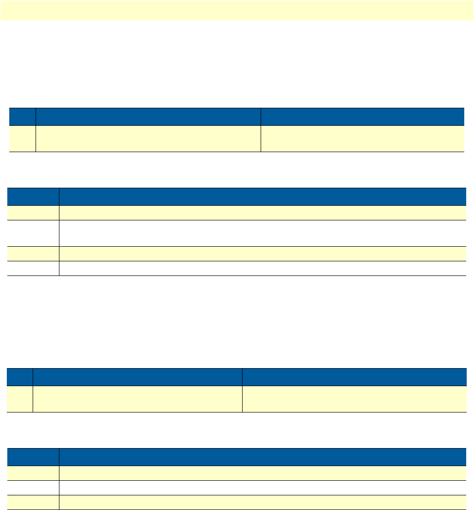
Access control list configuration task list 89
OnSite 2800 Series User Manual 7 • Access control list configuration
Binding and unbinding an access control list profile to an IP interface
The command use is used to bind an access control list profile to an IP interface. This procedure describes how
to bind an access control list profile to incoming packets on an IP interface
Mode: Profile access control list
Where the syntax is:
The no form of the use command is used to unbind an access control list profile from an interface. When
using this form the name of an access control list profile, represented by the name argument above, is not
required. This procedure describes how to unbind an access control list profile to incoming packets on an IP
interface
Mode: Interface
Where the syntax is:
Thus for each IP interface only one incoming and outgoing access control list can be active at the same time.
Example: Bind and unbind an access control list entries to an IP interface
Bind an access control list profile to incoming packets on the interface wan in the IP router context.
2800(cfg)#context ip router
2800(cfg-ip)[router]#interface wan
2800(cfg-if)[wan]#use profile acl WanRx in
Step Command Purpose
1node(if-ip)[if-name]#use profile acl name in Binds access control list profile name to incom-
ing packets on IP interface if-name
Keyword Meaning
if-name The name of the IP interface to which an access control list profile gets bound
name The name of an access control list profile that has already been created using the profile acl
command. This argument must be omitted in the no form
in Specifies that the access control list profile applies to incoming packets on this interface.
out Specifies that the access control list applies to outgoing packets on this interface.
Step Command Purpose
1node(if-ip)[if-name]#no use profile acl in Unbinds access control list profile for incoming pack-
ets on IP interface if-name
Keyword Meaning
if-name The name of the IP interface to which an access control list profile gets bound
in Specifies that the access control list profile applies to incoming packets on this interface.
out Specifies that the access control list applies to outgoing packets on this interface.

Access control list configuration task list 90
OnSite 2800 Series User Manual 7 • Access control list configuration
Unbind an access control list profile from an interface.
2800(cfg)#context ip router
2800(cfg-ip)[router]#interface wan
2800(cfg-if)[wan]#no use profile acl in
Note
When unbinding an access control list profile the name argument is
not required, since only one incoming and outgoing access control
list can be active at the same time on a certain IP interface.
Displaying an access control list profile
The show profile acl command displays the indicated access control list profile. If no specific profile is selected
all installed access control list profiles are shown. If an access control list is linked to an IP interface the number
of matches for each rule is displayed. If the access control list profile is linked to more than one IP interface, it
will be shown for each interface.
This procedure describes how to display a certain access control list profile
Mode: Administrator execution or any other mode, except the operator execution mode
Example: Displaying an access control list entries
The following example shows how to display the access control list profile named WanRx.
2800#show profile acl WanRx
IP access-list WanRx. Linked to router/wan/in.
deny icmp any any msg echo
permit ip 62.1.2.3 0.0.255.255 host 193.14.2.11
permit ip 97.123.111.0 0.0.0.255 host 193.14.2.11
permit tcp any host 193.14.2.10 eq 80
permit udp host 62.1.2.3 host 193.14.2.11 range 1024 2048
deny ip any any
Debugging an access control list profile
The debug acl command is used to debug the access control list profiles during system operation. Use the no
form of this command to disable any debug output.
This procedure describes how to debug the access control list profiles
Mode: Administrator execution or any other mode, except the operator execution
This procedure describes how to activate the debug level of an access control list profiles for a specific interface.
Step Command Purpose
1node#show profile acl name Displays the access control list profile name
Step Command Purpose
1node#debug acl Enables access control list debug monitor
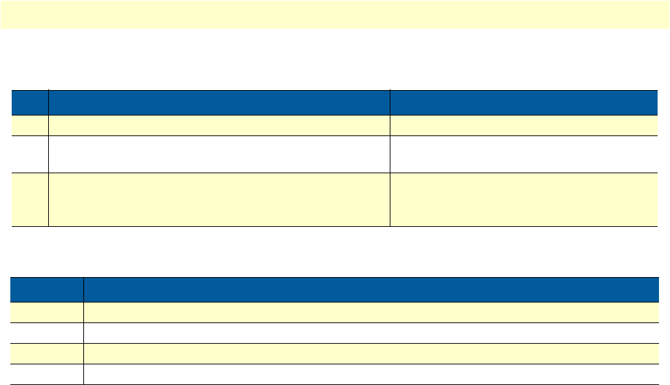
Access control list configuration task list 91
OnSite 2800 Series User Manual 7 • Access control list configuration
Mode: Interface
Where the syntax is:
Example: Debugging access control list profiles
The following example shows how to enable debugging for incoming traffic of access control lists on interface
wan. On level 7 all debug output is shown.
2800(cfg)#context ip router
2800(cfg-ip)[router]#interface wan
2800(cfg-if)[wan]#debug acl in 7
The following example enables the debug monitor for access control lists globally.
2800#debug acl
The following example disables the debug monitor for access control lists globally.
2800#no debug acl
Step Command Purpose
1node(cfg)#context ip router Selects the IP router context
2node(ctx-ip)[router]#interface if-name Selects IP interface if-name for which access
control list profile shall be debugged
3node(if-ip)[if-name]#debug acl {in | out} [level] Enables access control list debug monitor
with a certain debug level for the selected
interface if-name
Keyword Meaning
if-name The name of the IP interface to which an access control list profile gets bound
level The detail level. Level 0 disables all debug output, level 7 shows all debug output.
in Specifies that the settings for incoming packets are to be changed.
out Specifies that the settings for outgoing packets are to be changed.
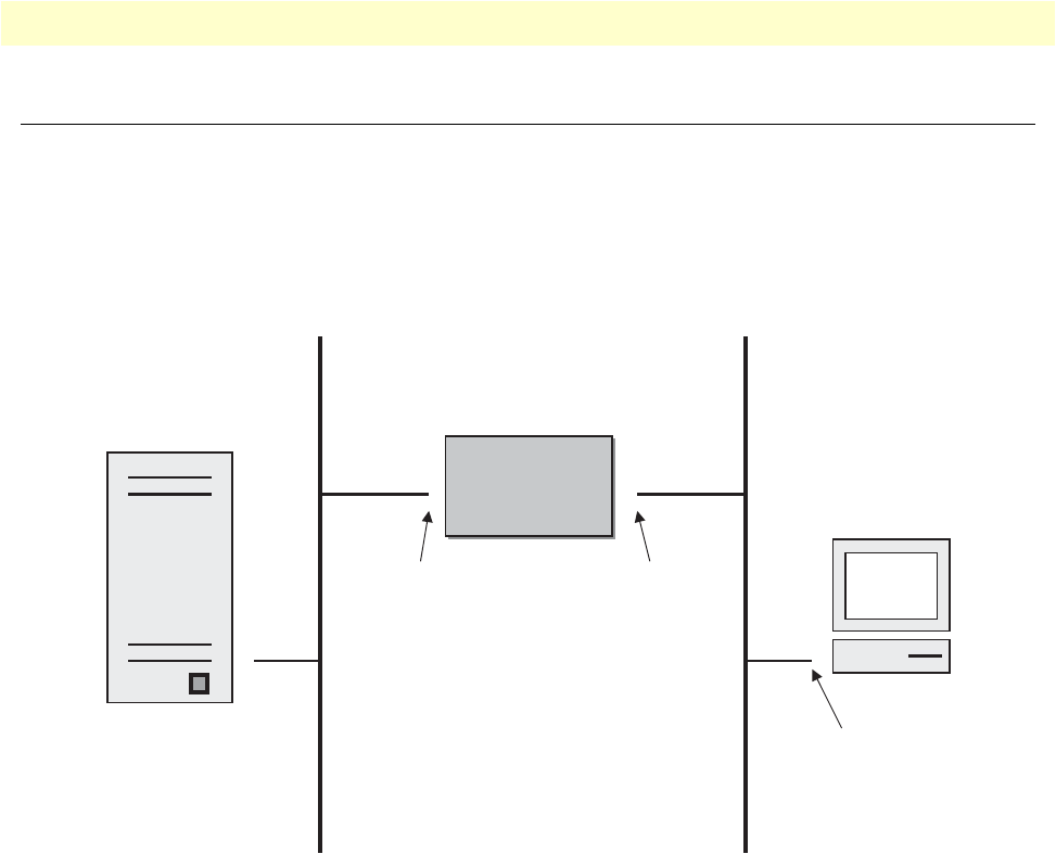
Examples 92
OnSite 2800 Series User Manual 7 • Access control list configuration
Examples
Denying a specific subnet
Figure 16 shows an example in which a server attached to network 172.16.1.0 shall not be accessible from outside
networks connected to IP interface lan of the OnSite device. To prevent access, an incoming filter rule named
Jamming is defined, which blocks any IP traffic from network 172.16.2.0 and has to be bound to IP interface lan.
Figure 16. Deny a specific subnet on an interface
The commands that have to be entered are listed below. The commands access the OnSite device via a Telnet
session running on a host with IP address 172.16.2.13, which accesses the OnSite via IP interface lan.
172.16.2.1>enable
172.16.2.1#configure
172.16.2.1(cfg)#profile acl Jamming
172.16.2.1(pf-acl)[Jamming]#deny ip 172.16.2.0 0.0.0.255 172.16.1.0 0.0.0.255
172.16.2.1(pf-acl)[Jamming]#permit ip any any
172.16.2.1(pf-acl)[Jamming]#exit
172.16.2.1(cfg)#context ip router
172.16.2.1(cfg-ip)[router]#interface lan
172.16.2.1(if-ip)[lan]#use profile acl Jamming in
172.16.2.1(if-ip)[lan]#exit
172.16.2.1(cfg-ip)#copy running-config startup-config
Host
Server
Node
Node
172.16.2.1/24172.16.1.1/24
secure lan
172.16.1.0 172.16.2.0
172.16.2.13/24

93
Chapter 8 Link scheduler configuration
Chapter contents
Introduction..........................................................................................................................................................94
Configuring access control lists..............................................................................................................................94
Configuring quality of service (QoS) .....................................................................................................................95
Applying scheduling at the bottleneck .............................................................................................................95
Using traffic classes .........................................................................................................................................95
Introduction to Scheduling .............................................................................................................................96
Priority ......................................................................................................................................................96
Weighted fair queuing (WFQ) ..................................................................................................................96
Shaping .....................................................................................................................................................97
Burst tolerant shaping or wfq ....................................................................................................................97
Hierarchy ..................................................................................................................................................97
Quick references....................................................................................................................................................98
Setting the modem rate ...................................................................................................................................98
Command cross reference ...............................................................................................................................99
Link scheduler configuration task list.....................................................................................................................99
Defining the access control list profile ...........................................................................................................100
Packet classification .................................................................................................................................100
Creating an access control list ..................................................................................................................101
Creating a service policy profile .....................................................................................................................102
Specifying the handling of traffic-classes ........................................................................................................104
Defining fair queuing weight ...................................................................................................................104
Defining the bit-rate ...............................................................................................................................105
Defining absolute priority .......................................................................................................................105
Defining the maximum queue length ......................................................................................................105
Specifying the type-of-service (TOS) field ...............................................................................................105
Specifying the precedence field ................................................................................................................106
Specifying differentiated services codepoint (DSCP) marking .................................................................106
Specifying layer 2 marking ......................................................................................................................107
Defining random early detection .............................................................................................................108
Discarding Excess Load ...........................................................................................................................108
Devoting the service policy profile to an interface .........................................................................................109
Displaying link arbitration status ..................................................................................................................110
Displaying link scheduling profile information .............................................................................................110
Enable statistics gathering .............................................................................................................................110

Introduction 94
OnSite 2800 Series User Manual 8 • Link scheduler configuration
Introduction
This chapter describes how to use and configure the OnSite Quality of Service (QoS) features. Refer to 7,
“Access control list configuration” on page 79 for more information on the use of access control lists.
This chapter includes the following sections:
•Quick references (see page 98)
•Packet Classification (see page 100)
•Assigning bandwidth to traffic classes (see page 98)
•Link scheduler configuration task list (see page 99)
QoS in networking refers to the capability of the network to provide a better service to selected network traffic.
This chapter shows you how to configure the OnSite router to best use the access link.
In many applications you can gain a lot by applying the minimal configuration found in the quick reference
section, but read sections “Applying scheduling at the bottleneck” and “Using traffic classes” first to under-
stand the paradox of why we apply a rate-limit to reduce delay and what a “traffic-class” means.
Configuring access control lists
Packet filtering helps to control packet movement through the network. Such control can help to limit net-
work traffic and to restrict network use by certain users or devices. To permit or deny packets from crossing
specified interfaces, the OnSite 2800 provides access control lists.
An access control list is a sequential collection of permit and deny conditions that apply to packets on a certain
interface. Access control lists can be configured for all routed network protocols (IP, ICMP, TCP, UDP, and
SCTP) to filter the packets of those protocols as the packets pass through an OnSite 2800. The 2800 tests
packets against the conditions in an access list one by one. The first match determines whether the OnSite
2800 accepts or rejects the packet. Because the OnSite 2800 stops testing conditions after the first match, the
order of the conditions is critical. If no conditions match, the software rejects the address.
For information and examples on how configure access control lists, refer to chapter 7, “Access control list con-
figuration” on page 79.
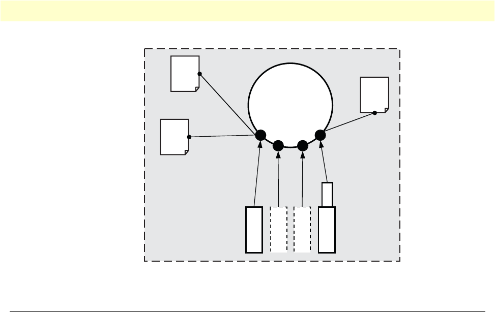
Configuring quality of service (QoS) 95
OnSite 2800 Series User Manual 8 • Link scheduler configuration
Figure 17. IP context and related elements
Configuring quality of service (QoS)
In the OnSite 2800, the link scheduler enables the definition of QoS profiles for network traffic on a certain
interface, as shown in figure 17. QoS refers to the ability of a network to provide improved service to selected
network traffic over various underlying technologies including Frame Relay, Ethernet and 802.x type net-
works, and IP-routed networks. In particular, QoS features provide improved and more predictable network
service by providing the following services:
•Supporting dedicated bandwidth
•Improving loss characteristics
•Avoiding and managing network congestion
•Shaping network traffic
•Setting traffic priorities across the network
Applying scheduling at the bottleneck
When an OnSite acts as an access router, the access link is the point where intelligent use of scarce resources
really makes a difference. Frequently, the access link modem is outside of the OnSite and the queueing would
happen in the modem, which does not distinguish between packet types. To improve QoS, you can configure
the OnSite to send no more data to the Internet than the modem can carry. This keeps the modem’s queue
empty and gives the OnSite control over which packet is sent over the access link at what time.
Using traffic classes
The link scheduler needs to distinguish between different types of packets. We refer to those types as “traffic-
classes”. You can think of the traffic-class as if every packet in the OnSite has a tag attached to it on which the
classification can be noted. The access control list “stage” (ACL) can be used to apply such a traffic-class name
to some type of packet based on its IP-header filtering capabilities. The traffic-class tags exist only inside the
OnSite router, but layer 2 priority bits (802.1pq class-of-service) and IP header type-of-service bits (TOS field)
Serial
PVC
IP
router
bind command
Service
Policy
Profile
Ethernet
use command
bind command
use command
NAPT
Profile
ACL
Profile
Context
Interfaces
Circuit
Ports
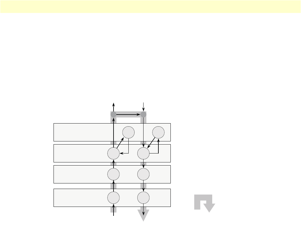
Configuring quality of service (QoS) 96
OnSite 2800 Series User Manual 8 • Link scheduler configuration
can be used to mark a specific packet type for the other network nodes. By default the traffic-class tag is empty.
Refer to figure 18 on page 96 when using the ACL to classify traffic. It illustrates the sequence of processing
stages every routed packet passes. Only stages that have been installed in the data path with a “use profile...”
statement in the corresponding interface configuration are present. Both an input direction ACL on the receiv-
ing interface as well as an output ACL on the transmitting interface can be used to classify a packet for special
handling by the output link scheduler on the transmit interface. But as visible from the figure no ACL can be
used for an input link scheduler.
Figure 18. Packet routing in OnSite
The QoS features in OnSite are a combination of an access control list (used for packet classification) and a ser-
vice-policy profile (used by the link arbiter to define the arbitration mode and the order in which packets of
different classes are served).
Introduction to Scheduling
Scheduling essentially means to determine the order in which packets of the different traffic-classes are served.
The following sections describe the ways this arbitration can be done.
Priority
One way of ordering packets is to give priority to one traffic-class and to serve the other traffic-classes when the
first has nothing to send. OnSite uses the priority scheme to make sure that voice packets generated by the
OnSite will experience as little delay as possible.
Weighted fair queuing (WFQ)
This arbitration method assures a given minimal bandwidth for each source. An example: you specify that traf-
fic-class A gets three times the bandwidth of traffic-class B. So A will get a minimum of 75% and B will get a
minimum of 25% of the bandwidth. But if no class A packets are waiting B will get 100% of the bandwidth.
Link Scheduler
Network address
translation (NAT)
Access control
list (ACL)
IPSec encryption/
decryption
Local applications (CLI, Web Server)
To/from network port (Ethernet, PPPoE,
Frame relay, etc.)
Routing
Sequence of processing stages
passed by a routed packet

Configuring quality of service (QoS) 97
OnSite 2800 Series User Manual 8 • Link scheduler configuration
Each traffic-class is in fact assigned a relative weight, which is used to share the bandwidth among the currently
active classes. Patton recommends that you specify the weight as percent which is best readable.
Shaping
There is another commonly used way to assign bandwidth. It is called shaping and it makes sure that each traf-
fic-class will get just as much bandwidth as configured and not more. This is useful if you have subscribed to a
service that is only available for a limited bandwidth e.g. low delay. When connecting the OnSite to a DiffServ
network shaping might be a required operation.
Burst tolerant shaping or wfq
For weighted fair queuing and shaping there is a variation of the scheduler that allows to specify if a traffic class
may temporarily receive a higher rate as long as the average stays below the limit. This burstiness measure
allows the network to explicitly assign buffers to bursty sources.
When you use shaping on the access link the shaper sometimes has the problem that multiple sources are
scheduled for the same time - and therefore some of them will be served too late. If the rate of every source had
to strictly obey its limit, all following packets would also have to be delayed by the same amount, and further
collisions would reduce the achieved rate even further. To avoid this effect, the OnSite shaper assumes that the
burstiness needed for sources to catch up after collisions is implicitly allowed. Future versions of OnSite might
allow setting the burst rate and bursting size if more control over its behavior is considered necessary.
Burst tolerance has a different effect when used with weighted fair queuing. Think of it as a higher initial rate
when a source device starts transmitting data packets. This allows giving a higher weight to short data transfers.
This feature is sometimes referred to as a service curve.
Hierarchy
An arbiter can either use wfq or shaping to determine which source to serve next. If you want the scheduler to
follow a combination of decision criteria you can combine different schedulers in hierarchy to do a multi-level
arbitration.Hierarchical scheduling is supported in OnSite with service-policy profiles used inside service-pol-
icy profiles.In figure 19 an example of hierarchical scheduling is illustrated. The 1
st
level arbiter Level_1 uses
weighted fair queuing to share the bandwidth among source classes VPN, Web and incorporates the traffic
from the 2
nd
level arbiter Low_Priority, which itself uses shaping to share the bandwidth among source classes
Mail and Default.
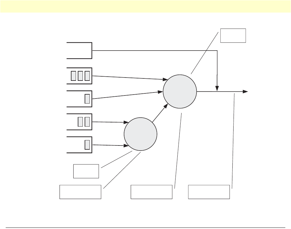
Quick references 98
OnSite 2800 Series User Manual 8 • Link scheduler configuration
Figure 19. Example of Hierarchical Scheduling
Quick references
The following sections provide a minimal “standard” link scheduler configuration for the case where a
(DSL/cable) modem link is shared for all traffic. You will also find a command cross reference list for adminis-
trators familiar with Cisco’s IOS QoS features and having to become acquainted with OnSite QoS configura-
tion.
Setting the modem rate
To match the data multiplexing of different traffic types to the capacity of the access link is the most common
application of the OnSite link scheduler.
1. Create a minimal profile.
profile service-policy modem-512
rate-limit 512 header-length 20 atm-modem
source traffic-class critical_q
priority
2. Apply the profile just created to the interface connected to the modem.
context ip
interface wan
use profile service-policy modem-512 out
Some explanations:
Low_Priority
Level_1
critical_q
VPN
Web
Mail
Default
priority
min. 30%
min. 40%
min. 30%
Define 2nd level
arbiter
Define 1st level
arbiter Use arbiter on
an interface
Mode
WFQ
Mode
Shaper

Link scheduler configuration task list 99
OnSite 2800 Series User Manual 8 • Link scheduler configuration
•“modem-512” is the title of the profile which is referred to when installing the scheduler
•“rate-limit 512” allows no more than 512 kbit/sec to pass which avoids queueing in the modem.
•“header-length 20” specifies how many framing bytes are added by the modem to “pack” the IP packet on
the link. The framing is taken into account by the rate limiter.
•“atm-modem” tells the rate limiter that the access link is ATM based. This option includes the ATM over-
head into the rate limit calculation. Please add 8 bytes to the header-length for AAL5 in this case.
•“source traffic-class” enters a sub-mode where the specific handling for a traffic-class is described. The list of
sources in the service-policy profile tells the arbiter which “traffic sources” to serve.
•“critical_q” is the traffic-class for the higheest priority packet streams that you have selected.
•“priority” means that packet of the source being described are always passed on immediately, packets of
other classes follow later if the rate limit permits.
Command cross reference
Comparing OnSite with the Cisco IOS QoS software command syntax often helps administrators to straight-
forwardly configure OnSite devices. In table 10 the Cisco IOS Release 12.2 QoS commands are in contrast
with the respective OnSite commands.
Link scheduler configuration task list
To configure QoS features, perform the tasks described in the following sections. Depending on your require-
ments some of the tasks are required while other tasks are optional.
•Defining the access control list profile
•Creating a service-policy profile (see page 102)
•Specifying the handling of traffic-classes (see page 104)
•Devoting the service policy profile to an interface (see page 109)
•Displaying link arbitration status (see page 110)
Table 10. Command cross reference
Action IOS command OnSite command
Specifies the name of the policy map or profile
to be created or modified.
policy-map policy-map-
name
profile service-policy
profile-name
Specifies the name of the class map or class to
be created.
class-map class-map-name source traffic-class class-
name
For IOS specifies average or peak bit rate
shaping. for the OnSite assigns the average bit
rate to a source.
shape {average | peak} cir
[bc] [be]
rate bit-rate
For IOS specifies or modifies the bandwidth
allocated for a class belonging to a policy
map. Percent defines the percentage of avail-
able bandwidth to be assigned to the class. for
the OnSite assigns the weight of the selected
source (only used with wfq).
bandwidth {bandwidth-
kbps | percent percent}
share percent-of-bandwidth
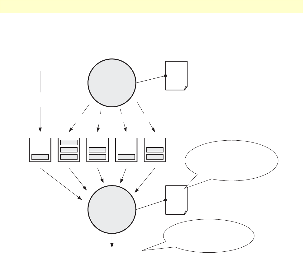
Link scheduler configuration task list 100
OnSite 2800 Series User Manual 8 • Link scheduler configuration
•Displaying link scheduling profile information (see page 110)
•Enable statistics gathering (see page 110)
Figure 20. Elements of link scheduler configuration
Defining the access control list profile
Packet classification
The basis for providing any QoS lies in the ability of a network device to identify and group specific packets.
This identification process is called packet classification. In OnSite access control lists are used for packet classi-
fication.
An access control list in OnSite consists of a series of packet descriptions like “addressed to xyz”. Those descrip-
tions are called rules. For each packet the list of descriptions is sequentially checked and the first rule that
matches decides what happens to the packet. As far as filtering is concerned the rule decides if the packet is dis-
carded (“deny”) or passed on (“permit”). You can also add a traffic-class to the rule and if this rule is the first
matching rule for a packet it is tagged with the traffic-class name.
Packet
Classification
ACL
Profile
Link Arbiter
Different Types (Classes) of Traffic
Predefined
Classes
IP Interface “wan”
Service
Policy
Profile
The service-policy profile
defines the arbitration
mode and order in which
packets of different
classes are served.
This interface is used as
access link and normally
represents the bottleneck
of the system.
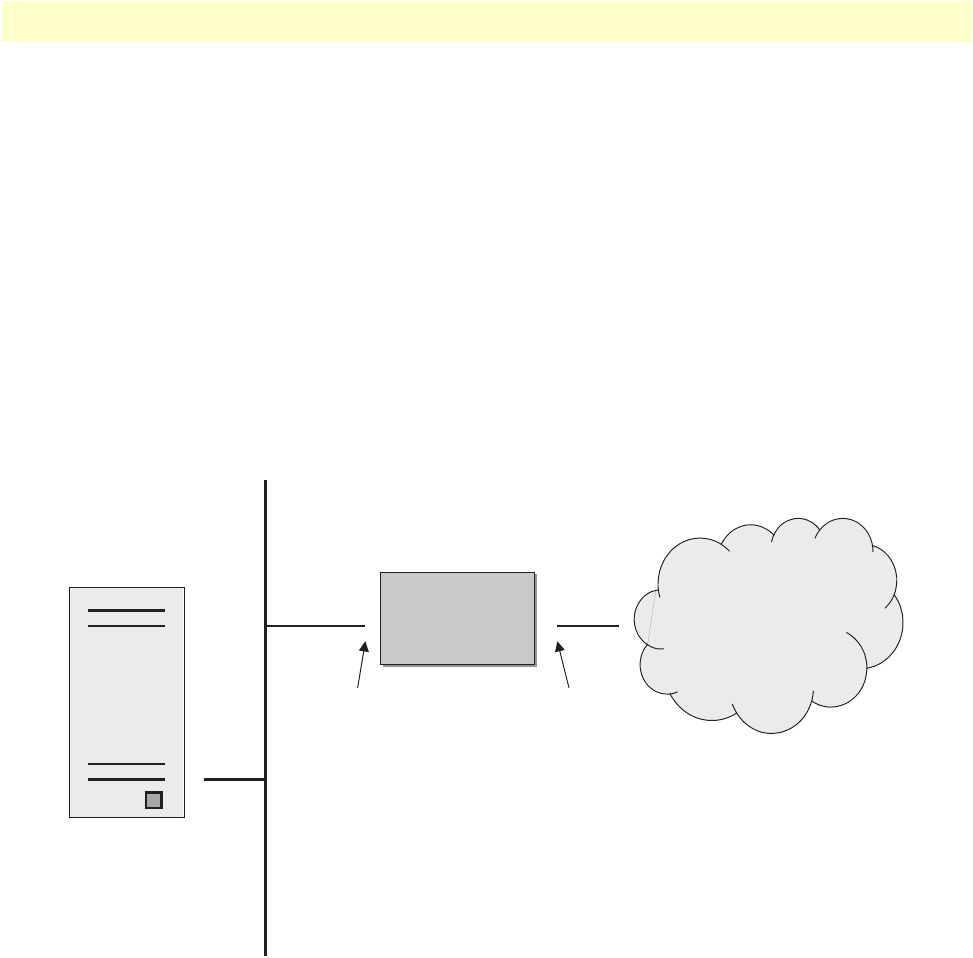
Link scheduler configuration task list 101
OnSite 2800 Series User Manual 8 • Link scheduler configuration
Some types of packets you do not have to tag with ACL. Voice and data packets from of for the OnSite itself
are automatically tagged with predefined traffic-class names: Predefined internal classes for data are:
•local-default—All other packets that originate from the OnSite itself.
•default—All traffic that has not otherwise been labeled.
Creating an access control list
The procedure to create an access control list is described in detail in chapter 7, “Access control list configura-
tion” on page 79.
At this point a simple example is given, that shows the necessary steps to tag any outbound traffic from a Web
server. The scenario is depicted in figure 21. The IP address of the Web server is used as source address in the
permit statement of the IP filter rule for the access control list.
Figure 21. Scenario with Web server regarded as a single source host
A new access control list has to be created. In the example above, the traffic-class that represents outbound
Web related traffic is named Web.
Access control list have an implicit “deny all” entry at the very end, so packets that do not match the first crite-
ria of outbound Web related traffic will be dropped. That is why a second access control list entry—one that
allows all other traffic—is necessary.
This procedure describes creating an access control list for tagging web traffic from the single source host at a
certain IP address.
Web-Server
172.16.1.20/24
Node
Node
17.254.0.91/16172.16.1.1/24
lan wan
172.16.1.0
IP Access
Network

Link scheduler configuration task list 102
OnSite 2800 Series User Manual 8 • Link scheduler configuration
Mode: Configure
Example: Defining the access control list profile
In the example below a new access control list profile named Webserver is created. In addition an IP access con-
trol list entry that permits access for host at IP address 172.16.1.20, and specifies that packets matched by this
rule belong to the traffic-class Web is added. Finally an IP access control list entry that permits IP traffic to or
from all IP addresses is added to the access control list.
2800(cfg)#profile acl Webserver
2800(pf-acl)[Webserv~]#permit ip host 172.16.1.20 any traffic-class Web
2800(pf-acl)[Webserv~]#permit ip any any
After packet classification is done using access control lists, the link arbiter needs rules defining how to handle the
different traffic-classes. For that purpose you create a service-policy profile. The service policy profile defines how
the link arbiter has to share the available bandwidth among several traffic classes on a certain interface.
Creating a service policy profile
The service-policy profile defines how the link scheduler should handle different traffic-classes. The overall
structure of the profile is as follows:
Step Command Purpose
1node(cfg)#profile acl name Creates a new access
control list profile named
name
2node(pf-acl)[name]#permit ip host ip-address any traffic-class
class-name
Creates an IP access con-
trol list entry that permits
access for host at IP
address ip-address, and
specifies that packets
matched by this rule
belong to the traffic-class
class-name.
3node(pf-acl)[name]#permit ip any any Creates an IP access con-
trol list entry that permits
IP traffic to or from all IP
addresses.

Link scheduler configuration task list 103
OnSite 2800 Series User Manual 8 • Link scheduler configuration
Figure 22. Structure of a Service-Policy Profile
The template shown above specifies an arbiter with three inputs which we call “sources”: x, y and “default”.
The traffic-class “default” stands for all other packets that belong neither to traffic-class x nor y. There is no
limit on the number of sources an arbiter can have.
Example: Creating a service policy profile
The following example shows how to create a top service-policy profile named sample. This profile does not
include any hierarchical sub-profiles. The bandwidth of the outbound link is limited to 512 kbps therefore the
interface rate-limit is set to 512. In addition weighted fair queuing (wfq) is used as arbitration scheme among
the source classes.
profile service-policy sample
rate-limit 512
mode wfq
source traffic-class Web
share 30
source traffic-class local-default
share 20
source traffic-class default
queue-limit 40
share 50
The first line specifies the name of the link arbiter profile to configure. On the second line the global band-
width limit is set. The value defining the bandwidth is given in kilobits per second. Each service-policy profile
must have a “rate-limit” except if no scheduling is used i.e. the link scheduler is used for packet marking only
(like setting the TOS byte).
How the bandwidth on an IP interface is shared among the source classes is defined on the third line. The
mode command allows selecting between the weighted fair queuing and shaping arbitration mode. The default
mode is wfq - the command shown above can therefore be omitted.
The following lines configure the source traffic-classes. When using weighted fair queuing (wfq) each user-
specified source traffic-class needs a value specifying its share of the overall bandwidth. For this purpose the
share command is used, which defines the relative weights of the source traffic-classes and policies.
profile service-policy <profile-name>
common settings link rate, arbitratio
n
source traffic-class <x>
settings for class x
source traffic-class <y>
settings for class y
source traffic-class default
settings for all other
traffic-classes not listed
common parameters
bandwidth, packet mark
queue-size, etc.

Link scheduler configuration task list 104
OnSite 2800 Series User Manual 8 • Link scheduler configuration
At a some point the source traffic-class default must be listed. This class must be present, because it defines how
packets, which do not belong to any of the traffic-classes listed in the profile are to be handled. When all listed
“traffic-classes” have “priority” the handling of the remaining traffic is implicitly defined and the “default” sec-
tion can be omitted. Similarly if no scheduling is used i.e. the link scheduler is used for packet marking only
(e.g. setting the TOS byte) the “default” section can also be omitted.
The table below shows the basic syntax of the service-policy profile structure:
Mode: Configure
Specifying the handling of traffic-classes
Several commands are available to specify what happens to a packet of a specific traffic-class.
Defining fair queuing weight
The command share is used with wfq link arbitration to assign the weight to the selected traffic-class. When
defining a number of source classes, the values are relative to each other. It is recommended to split 100—
which can be read as 100%—among all available source classes, e.g. with 20, 30 and 50 as value for the respec-
tive share commands, which represent 20%, 30% and 50%.
Step Command Purpose
1node(cfg)# profile service-policy name Creates a new service policy profile
named name
2node(pf-srvpl)[name]#rate-limit value Limits global interface rate to value in
kbps. Be aware, that the actual rate-
limit on a given interface has to be
defined for reliable operation.
3node(pf-srvpl)[name]#mode {shaper | wfq} Sets the arbitration scheme to mode
shaper or weighted fair queuing (wfq).
If not specified wfq is default.
4node(pf-srvpl)[name]#source {traffic-class | policy}
src-name
Enters source configuration mode for a
traffic-class or a hierarchical lower
level service-policy profile named src-
name.
5node (src)[src-name]… At this point the necessary commands
used to specify the handling of the traf-
fic-class(es) have to be entered.
6node (src)[src-name]exit Leaves the source configuration mode
(optional)
7node(pf-srvpl)[name]#… Repeat steps 4 to 6 for all necessary
source classes or lower level service
policy profiles.
8node(pf-srvpl)[name]#exit Leaves the service-policy profile mode

Link scheduler configuration task list 105
OnSite 2800 Series User Manual 8 • Link scheduler configuration
Mode: Source
Defining the bit-rate
The command rate is used with shaper link arbitration to assign the (average) bit-rate to the selected source.
When enough bandwidth is available each source will exactly receive this bandwidth (but no more), when
overloaded the shaper will behave like a wfq arbiter. Bit-rate specification for shaper (kilobits).
Mode: Source
Defining absolute priority
This command priority can only be applied to classes, but not to lower level polices. The class is given absolute
priority effectively bypassing the link arbiter. Care should be taken, as traffic of this class may block all other
traffic. The packets given “priority” are taken into account by the “rate-limit”. Use the command police to
control the amount of “priority” traffic.
Mode: Source
Defining the maximum queue length
The command queue-limit specifies the maximum number of packets queued for the class name. Excess pack-
ets are dropped. Used in “class” mode—queuing only happens at the leaf of the arbitration hierarchy tree. The
no form of this command reverts the queue-limit to the internal default value, which depends on
your configuration.
Mode: Source
Specifying the type-of-service (TOS) field
The set ip tos command specifies the type-of-service (TOS) field value applied to packets of the class name. TOS
and DSCP markings cannot be used at the same time. The no form of this command disables TOS marking.
Command Purpose
node(src)[name]#share percentage Defines fair queuing weight (relative to other sources) to percent-
age for the selected class or policy name
Command Purpose
node(src)[name]#rate [kilobits |
remaining]
Defines the (average) bit-rate to the selected in kbps kilobits or as
remaining if a second priority source is getting the unused band-
width for the selected class or policy name
Command Purpose
node(src)[name]#priority Defines absolute priority effectively bypassing the link arbiter for the
selected class or policy name
Command Purpose
node(src)[name]#queue-limit
number-of-packets
Defines the maximum number of packets queued for the selected class
or policy name

Link scheduler configuration task list 106
OnSite 2800 Series User Manual 8 • Link scheduler configuration
The type-of-service (TOS) byte in an IP header specifies precedence (priority) and type of service (RFC791,
RFC1349). The precedence field is defined by the first three bits and supports eight levels of priority. The next
four bits—which are set by the set ip tos command—determine the type-of-service (TOS).
Historically those bits had distinct meanings but since they were never consistently applied routers will ignore
them by default. Nevertheless you can configure your routers to handle specific TOS values and OnSite allows
you to inspect the TOS value in the ACL rules and to modify the TOS value with the link scheduler set ip tos
command.
Mode: Source
Specifying the precedence field
The set ip precedence command specifies the precedence marking applied to packets of the class name. Pre-
cedence and DSCP markings cannot be used at the same time.
The type-of-service (TOS) byte in an IP header specifies precedence (priority) and type of service (RFC791,
RFC1349). The precedence field is defined by the first three bits and supports eight levels of priority. The low-
est priority is assigned to 0 and the highest priority is 7.
The no form of this command disables precedence marking.
Mode: Source
Specifying differentiated services codepoint (DSCP) marking
Differentiated services enhancements to the Internet protocol are intended to enable the handling of “traffic-
classes” throughout the Internet. In this context the IP header TOS field is interpreted as something like a
Table 11. TOS values and their meaning
TOS Value OnSite Value Meaning
1000 8Minimize delay.
0100 4Maximize throughput.
0010 2Maximizes reliability.
0001 1Minimize monetary costs.
0000 0All bits are cleared, normal service, “default TOS”.
Command Purpose
node(src)[name]#set ip tos value Defines the type-of-service (TOS) value applied to packets of for the
selected class or policy name. Standard ToT values are 0, 1, 2, 4,
and 8, as given in
table 11
on page 106, but any number from 0 to
15 can be configured.
Command Purpose
node(src)[name]#set ip precedence value Defines the precedence marking value applied to pack-
ets of for the selected class or policy name. The range
for value is from 0 to 7, but only values from 0 to 5
should be used.

Link scheduler configuration task list 107
OnSite 2800 Series User Manual 8 • Link scheduler configuration
“traffic-class” number called. With OnSite you can inspect the DSCP value in the ACL rules and modify the
DSCP value with the link scheduler set ip dscp command.
Note
When configuring service differentiation on the OnSite router,
ensure that codepoint settings are arranged with the service provider.
The command set ip dscp sets the DS field applied to packets of the class name. Additionally shaping may be
needed to make the class conformant. The no form of this command disables packet marking.
Mode: Source
Specifying layer 2 marking
The IEEE ratified the 802.1p standard for traffic prioritization in response to the realization that different traf-
fic classes have different priority needs. This standard defines how network frames are tagged with user priority
levels ranging from 7 (highest priority) to 0 (lowest priority). 802.1p-compliant network infrastructure devices,
such as switches and routers, prioritize traffic delivery according to the user priority tag, giving higher priority
frames precedence over lower priority or non-tagged frames. This means that time-critical data can receive
preferential treatment over non-time-critical data.
Under 802.1p, a 4-byte Tag Control Info (TCI) field is inserted in the Layer 2 header between the Source
Address and the MAC Client Type/Length field of an Ethernet Frame. Table 12 lists the tag components.
802.1p-compliant infrastructure devices read the 3-bit user priority field and route the frame through an inter-
nal buffer/queue mapped to the corresponding user priority level.
The command set layer2 cos specifies the layer 2 marking applied to packets of this class by setting the 3-bit
priority field (802.1p). The no form of this command disables packet marking.
Please note that the Ethernet port must be configured for 802.1Q framing. Standard framing has no class-of-
service field.
Mode: Source
Command Purpose
node(src)[name]#set ip dscp value Defines the Differentiated Services Codepoint value applied to
packets of for the selected class or policy name. The range for
value is from 0 to 63.
Table 12. Traffic control info (TCI) field
Tag Control Field Description
Tagged Frame Type Interpretation Always set to 8100h for Ethernet frames (802.3ac tag format)
3-Bit Priority Field (802.1p) Value from 0 to 7 representing user priority levels (7 is the highest)
Canonical Always set to 0
12-Bit 802.1Q VLAN Identifier VLAN identification number
Command Purpose
node(src)[name]#set layer2 cos value Defines the Class-Of-Service value applied to packets of for the
selected class or policy name. The range for value is from 0 to 7.

Link scheduler configuration task list 108
OnSite 2800 Series User Manual 8 • Link scheduler configuration
Defining random early detection
The command random-detect is used to request random early detection (RED). When a queue carries lots of
TCP transfers that last longer than simple web requests, there is a risk that TCP flow-control might be ineffi-
cient. A burst-tolerance index between 1 and 10 may optionally be specified (exponential filter weight). The no
form of this command reverts the queue to default “tail-drop” behavior.
Mode: Source
Discarding Excess Load
The command police controls traffic arriving in a queue for class name. The value of the first argument aver-
age-kilobits defines the average permitted rate in kbps, the value of the second argument kilobits-ahead defines
the tolerated burst size in kbps ahead of schedule. Excess packets are dropped.
This procedure describes defining discard excess load
Mode: Source
Command Purpose
node(src)[name]#random-detect {burst-tolerance}Defines random early detection (RED) for
queues of for the selected traffic-class or policy
name. The range for the optional value burst-
tolerance is from 1 to 10.
Command Purpose
node(src)[name]#police average-kilobits
burst-size kilobits-ahead
Defines how traffic arriving in a queue for the selected
class or policy name has to be controlled. The value aver-
age-kilobits for average rate permitted is in the range
from 0 to 10000 kbps. The value kilobits-ahead for burst
size tolerated ahead of schedule is in the range from 0 to
10000.
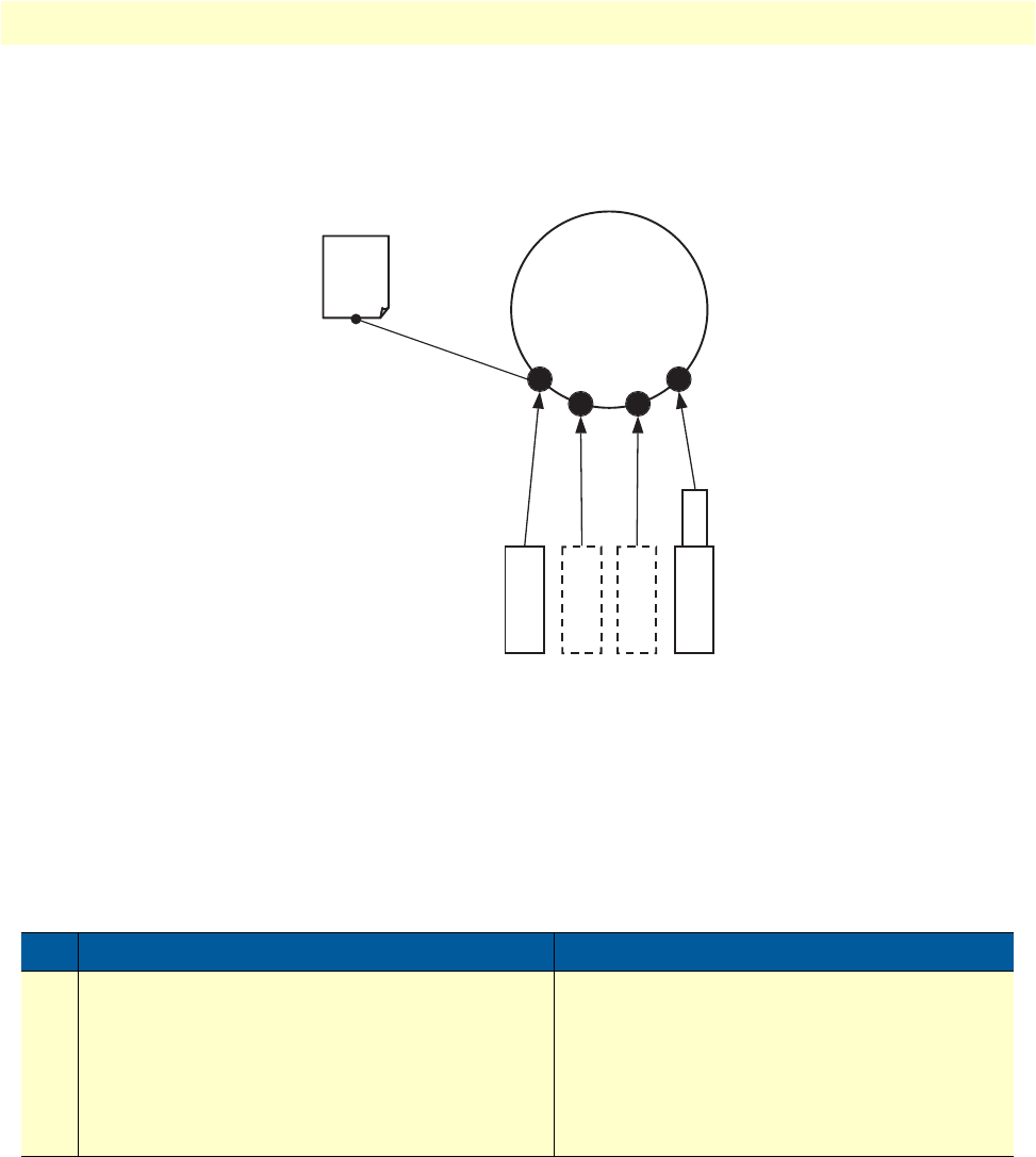
Link scheduler configuration task list 109
OnSite 2800 Series User Manual 8 • Link scheduler configuration
Devoting the service policy profile to an interface
Any service policy profile needs to be bound to a certain IP interface to get activated. According the terminol-
ogy of OnSite a service policy profile is used on a certain IP interface, as shown in figure 23.
Figure 23. Using a Service Policy Profile on an IP Interface
Therefore the use profile service-policy command allows attaching a certain service policy profile to an IP
interface that is defined within the IP context. This command has an optional argument that defines whether
the service policy profile is activated in receive or transmit direction.
Providers may use input shaping to improve downlink voice jitter in the absence of voice support. The default
setting no service-policy sets the interface to FIFO queuing.
Mode: Interface
Example: Devoting the service policy profile to an interface
The following example shows how to attach the service policy profile Voice_Prio to the IP interface wan that is
defined within the IP context for outgoing traffic.
Step Command Purpose
1node(if-ip)[if-name]#use profile service-
policy name {in | out}
Applies the service policy profile name to the
selected interface if-name. Depending on select-
ing the optional in or out argument the service
policy profile is active on the receive or transmit
direction. Be aware that service policy profiles
can only be activated on the transmit direction at
the moment.
Context
IP
“router”
use command
Service
Policy
Profile
bind command
PVC Serial
Ethernet

Link scheduler configuration task list 110
OnSite 2800 Series User Manual 8 • Link scheduler configuration
2800>enable
2800#configure
2800(cfg)#context ip router
2800(ctx-ip)[router]#interface wan
2800(if-ip)[wan]#use profile service-policy Voice_Prio out
Displaying link arbitration status
The show service-policy command displays link arbitration status. This command supports the optional
argument interface that select a certain IP interface. This command is available in the operator mode.
Mode: Operator execution
Example: Displaying link arbitration status
The following example shows how to display link arbitration status information.
2800>show service-policy
available queue statistics
--------------------------
default
- packets in queue: 10
Displaying link scheduling profile information
The show profile service-policy command displays link scheduling profile information of an existing ser-
vice-policy profile. This command is only available in the administrator mode.
Mode: Administrator execution
Example: Displaying link scheduling profile information
The following example shows how to display link scheduling profile information of an existing service-policy
profile VoIP_Layer2_CoS.
2800#show profile service-policy VoIP_Layer2_CoS
VoIP_Layer2_CoS
default (mark layer 2 cos -1)
Enable statistics gathering
Using the debug queue statistics commands enables statistic gathering of link scheduler operations.
Step Command Purpose
1node>show service-policy {interface name}Displays the link arbitration status
Step Command Purpose
1node#show profile service-policy name Displays link scheduling profile information of the
service-policy profile name

Link scheduler configuration task list 111
OnSite 2800 Series User Manual 8 • Link scheduler configuration
The command has optional values (in the range of 1 to 4) that define the level of detail (see table 13).
Note
The debug features offered by OnSite require the CPU resources of
your OnSite router. Therefore do not enable statistic gathering or
other debug features if it is not necessary. Disable any debug feature
after use with the no form of the command.
You can enable queue statistics for all queues of a link scheduler by placing the debug queue statistics com-
mand in the profile header. Queue statistics are reset whenever the configuration is changed or OnSite is
reloaded.
Mode: Source
Example: Enable statistics gathering for all queues of a profile
The following example shows how to enable statistic gathering for all traffic-classes
2800>enable
2800#configure
2800(cfg)#profile service-policy sample
2800(pf-srvpl)[sample]#debug queue statistics 4
Table 13. Values defining detail of the queuing statistics
Optional Value Implication on Command Output
0Statistic gathering is switched off
1Display amount of packets passed (did
not have to wait), queued (arrived ear-
lier than rate permitted) and discarded
(due to overflowing queue)
2Also collects byte counts for the catego-
ries listed above
3Also keeps track of the peek queue
lengths ever reached since the last con-
figuration change or reload
4Adds delay time monitoring
Step Command Purpose
1node(src)[name]#debug queue statistics level Enables statistic gathering for the selected class
or policy name. The optional argument level,
which is in the range from 1 to 4, defines the ver-
bosity of the command output.

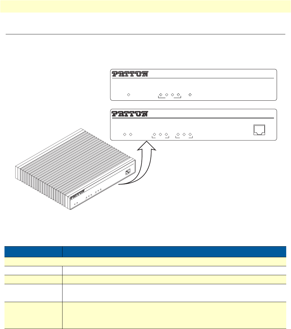
Status LEDs 113
OnSite 2800 Series User Manual 9 • LEDs status and monitoring
Status LEDs
This chapter describes OnSite gateway router front panel LEDs. Figure 24 shows OnSite 2800 Series LEDs.
LED definitions are listed in table 14 on page 113.
Figure 24. Examples of OnSite 2800 Series front panels
Table 14. OnSite LED Indications
LED Description
Note If an error occurs, all LEDs will flash once per second.
Power When lit, indicates power is applied. Off indicates no power applied.
Run When lit, indicates normal operation. Flashes once per second during boot (startup).
Serial • STATUS: Lit when serial link is up.
• ACTIVITY: Flashes when serial data is transmitted or received from the unit.
Ethernet (each port) • Link: Lit when Ethernet link is up.
• 100M: On when 100-Mbps Ethernet is selected.
• Activity: Flashes when data is received or transmitted from the unit to the LAN.
IPLink VPN Router
Link
100M
Activity
Enet 0
IPLink VPN Router
Run
Link
100M
Activity
Enet 1
Power
Console
Link
100M
Activity
Enet 0
Power
Console
IPLink VPN Router
Run
Link
100M
Activity
Enet 1
IPLink 2805
IPLink 2800
LAN WAN
1234
Power

114
Chapter 10 Contacting Patton for assistance
Chapter contents
Introduction........................................................................................................................................................115
Contact information............................................................................................................................................115
Patton Support Headquarters in the USA .....................................................................................................115
Alternate Patton support for Europe, Middle Ease, and Africa (EMEA) ........................................................115
Warranty Service and Returned Merchandise Authorizations (RMAs).................................................................115
Warranty coverage ........................................................................................................................................115
Out-of-warranty service ...........................................................................................................................116
Returns for credit ....................................................................................................................................116
Return for credit policy ...........................................................................................................................116
RMA numbers ..............................................................................................................................................116
Shipping instructions ..............................................................................................................................116

Introduction 115
OnSite 2800 Series User Manual 10 • Contacting Patton for assistance
Introduction
This chapter contains the following information:
•“Contact information”—describes how to contact Patton technical support for assistance.
•“Warranty Service and Returned Merchandise Authorizations (RMAs)”—contains information about the
RAS warranty and obtaining a return merchandise authorization (RMA).
Contact information
Patton Electronics offers a wide array of free technical services. If you have questions about any of our other
products we recommend you begin your search for answers by using our technical knowledge base. Here, we
have gathered together many of the more commonly asked questions and compiled them into a searchable
database to help you quickly solve your problems.
Patton Support Headquarters in the USA
•Online support—available at http://www.patton.com
•E-mail support—e-mail sent to support@patton.com will be answered within 1 business day
•Telephone support—standard telephone support is available five days a week—from 8:00 am to 5:00 pm
EST (1300 to 2200 UTC)—by calling +1 (301) 975-1007
•Fax—+1 (253) 663-5693
Alternate Patton support for Europe, Middle Ease, and Africa (EMEA)
•Online support—available at http://www.patton-inalp.com
•E-mail support—email sent to support@patton-inalp.com will be answered within 1 day
•Telephone support—standard telephone support is available five days a week—from 8:00 am to 5:00 pm
CET (0900 to 1800 UTC/GMT)—by calling +41 (0) 31 985 25 55
•Fax—+41 (0) 31 985 25 26
Warranty Service and Returned Merchandise Authorizations (RMAs)
Patton Electronics is an ISO-9001 certified manufacturer and our products are carefully tested before ship-
ment. All of our products are backed by a comprehensive warranty program.
Note
If you purchased your equipment from a Patton Electronics reseller,
ask your reseller how you should proceed with warranty service. It is
often more convenient for you to work with your local reseller to
obtain a replacement. Patton services our products no matter how
you acquired them.
Warranty coverage
Our products are under warranty to be free from defects, and we will, at our option, repair or replace the prod-
uct should it fail within one year from the first date of shipment. Our warranty is limited to defects in work-
manship or materials, and does not cover customer damage, lightning or power surge damage, abuse, or
unauthorized modification.

Warranty Service and Returned Merchandise Authorizations (RMAs) 116
OnSite 2800 Series User Manual 10 • Contacting Patton for assistance
Out-of-warranty service
Patton services what we sell, no matter how you acquired it, including malfunctioning products that are no
longer under warranty. Our products have a flat fee for repairs. Units damaged by lightning or other catastro-
phes may require replacement.
Returns for credit
Customer satisfaction is important to us, therefore any product may be returned with authorization within 30
days from the shipment date for a full credit of the purchase price. If you have ordered the wrong equipment or
you are dissatisfied in any way, please contact us to request an RMA number to accept your return. Patton is
not responsible for equipment returned without a Return Authorization.
Return for credit policy
•Less than 30 days: No Charge. Your credit will be issued upon receipt and inspection of the equipment.
•30 to 60 days: We will add a 20% restocking charge (crediting your account with 80% of the purchase price).
•Over 60 days: Products will be accepted for repairs only.
RMA numbers
RMA numbers are required for all product returns. You can obtain an RMA by doing one of the following:
•Completing a request on the RMA Request page in the Support section at http://www.patton.com
•By calling +1 (301) 975-1007 and speaking to a Technical Support Engineer
•By sending an e-mail to returns@patton.com
All returned units must have the RMA number clearly visible on the outside of the shipping container. Please use
the original packing material that the device came in or pack the unit securely to avoid damage during shipping.
Shipping instructions
The RMA number should be clearly visible on the address label. Our shipping address is as follows:
Patton Electronics Company
RMA#: xxxx
7622 Rickenbacker Dr.
Gaithersburg, MD 20879-4773 USA
Patton will ship the equipment back to you in the same manner you ship it to us. Patton will pay the return
shipping costs.

117
Appendix A Compliance information
Chapter contents
Compliance .........................................................................................................................................................118
EMC .............................................................................................................................................................118
Safety ............................................................................................................................................................118
PSTN Regulatory ..........................................................................................................................................118
Radio and TV Interference (FCC Part 15) ..........................................................................................................118
CE Declaration of Conformity ............................................................................................................................118
Authorized European Representative ...................................................................................................................119
FCC Part 68 (ACTA) Statement (Model 2803 only)...........................................................................................119
Industry Canada Notice (Model 2803 only)........................................................................................................119

Compliance 118
OnSite 2800 Series User Manual A • Compliance information
Compliance
EMC
•FCC Part 15, Class A
•EN55022, Class A
•EN55024
Safety
•UL 60950-1/CSA C22.2 N0.60950-1
•IEC/EN60950-1
•AS/NZS 60950-1
PSTN Regulatory
•ACTA Part 68 (Model 2803)
•CS03 (Model 2803)
•AS/ACIF S016 (Model 2803)
Radio and TV Interference (FCC Part 15)
The OnSite router generates and uses radio frequency energy, and if not installed and used properly-that is, in
strict accordance with the manufacturer’s instructions-may cause interference to radio and television reception.
The OnSite router have been tested and found to comply with the limits for a Class A computing device in
accordance with specifications in Subpart B of Part 15 of FCC rules, which are designed to provide reasonable
protection from such interference in a commercial installation. However, there is no guarantee that interfer-
ence will not occur in a particular installation. If the OnSite router does cause interference to radio or television
reception, which can be determined by disconnecting the unit, the user is encouraged to try to correct the
interference by one or more of the following measures: moving the computing equipment away from the
receiver, re-orienting the receiving antenna and/or plugging the receiving equipment into a different AC outlet
(such that the computing equipment and receiver are on different branches).
CE Declaration of Conformity
This equipment conforms to the requirements of Council Directive 1999/5/EC on the approximation of the
laws of the member states relating to Radio and Telecommunication Terminal Equipment and the mutual rec-
ognition of their conformity.
The safety advice in the documentation accompanying this product shall be obeyed. The conformity to the
above directive is indicated by the CE sign on the device. The signed Declaration of Conformity can be down-
loaded from the Patton website at www.patton.com/certifications.

Authorized European Representative 119
OnSite 2800 Series User Manual A • Compliance information
Authorized European Representative
D R M Green
European Compliance Services Limited.
Oakdene House, Oak Road
Watchfield,
Swindon, Wilts SN6 8TD, UK
FCC Part 68 (ACTA) Statement (Model 2803 only)
This equipment complies with Part 68 of FCC rules and the requirements adopted by ACTA. On the bottom
side of this equipment is a label that contains—among other information—a product identifier in the format
US: AAAEQ##TXXXX. If requested, this number must be provided to the telephone company.
A plug and jack used to connect this equipment to the premises wiring and telephone network must comply
with the applicable FCC Part 68 rules and requirements adopted by the ACTA.
This equipment uses a Universal Service Order Code (USOC) jack: RJ-11C.
If this equipment causes harm to the telephone network, the telephone company will notify you in advance
that temporary discontinuance of service may be required. But if advance notice isn’t practical, the telephone
company will notify the customer as soon as possible. Also, you will be advised of your right to file a complaint
with the FCC if you believe it is necessary.
The telephone company may make changes in its facilities, equipment, operations or procedures that could
affect the operation of the equipment. If this happens the telephone company will provide advance notice in
order for you to make necessary modifications to maintain uninterrupted service.
If trouble is experienced with this equipment, for repair or warranty information, please contact our company.
If the equipment is causing harm to the telephone network, the telephone company may request that you dis-
connect the equipment until the problem is resolved.
Connection to party line service is subject to state tariffs. Contact the state public utility commission, public
service commission or corporation commission for information.
Industry Canada Notice (Model 2803 only)
This equipment meets the applicable Industry Canada Terminal Equipment Technical Specifications. This is
confirmed by the registration number. The abbreviation, IC, before the registration number signifies that reg-
istration was performed based on a Declaration of conformity indicating that Industry Canada technical speci-
fications were met. It does not imply that Industry Canada approved the equipment.

120
Appendix B Specifications
Chapter contents
Ethernet interfaces...............................................................................................................................................121
Sync serial interface .............................................................................................................................................121
T1/E1 interface (Model 2803 only).....................................................................................................................121
PPP support ........................................................................................................................................................121
IP services............................................................................................................................................................122
Management .......................................................................................................................................................122
Operating environment .......................................................................................................................................122
Operating temperature ..................................................................................................................................122
Operating humidity ......................................................................................................................................122
System.................................................................................................................................................................122
Dimensions .........................................................................................................................................................122
Power supply .......................................................................................................................................................123
Internal AC version .......................................................................................................................................123
12VDC version with External AC Power Adapter
(Models 2802, 2821, 2835) ..........................................................................................................................123
5VDC Version with External Power Adapter (Model 2805) .........................................................................123

Ethernet interfaces 121
OnSite 2800 Series User Manual B • Specifications
Ethernet interfaces
10/100Base-TX Ethernet WAN port
4-port 10/100Base-TX Ethernet LAN switch (Model 2805)
10/100Base-TX Ethernet LAN port (all other models)
All ports full duplex, autosensing, auto-MDIX 10/100 Full Duplex/Autosensing Ethernet RJ-45
Sync serial interface
ITU-T X.21 or V.35 interface
Female DB-15 and DB-25 connectors (receptacles)
DTE orientation. (DCE orientation for X.21 is available from the Patton factory upon special request).
T1/E1 interface (Model 2803 only)
•T1: RJ-48C connector (receptacle)
•E1: RJ-48C connector (receptacle) and dual BNC coaxial connectors (receptacles)
•Line Rate
-1.544 Mbps (T1) in accordance with ANSI T1.403
-2.048 Mbps (E1) in accordance with ITU-T G.703
•Line Coding
-T1 AMI or B8ZS (default), selectable
-E1 AMI or HDB3 (default), selectable
•Clocking is software selectable as Internal or Network Timing source (default)
•T1 Line Build-out
-Transmit: Selectable for 0, -7.5, -15, -22.5 dB
-Receive: Automatic
•Line Framing
-T1 ESF (default) and unframed
-E1 CRC (default), non-CRC-4, and unframed
•Isolation 1,500 Vrms
PPP support
X.21 or V.35 WAN
Frame-Relay (8 PVCs)
RFC1490, FRF.12 fragmentation
LMI, Q.933D, ANSI 617D, Gang of Four

IP services 122
OnSite 2800 Series User Manual B • Specifications
PPP, PAP, CHAP, LCP, IPCP
IP services
IPv4 router; RIPv1, v2 (RFC 1058 and 2453)
Programmable static routes
ICMP redirect (RFC 792); Packet fragmentation
DiffServe/ToS set or queue per header bits
Packet Policing discards excess traffic
802.1p VLAN tagging
IPSEC AH & ESP Modes
Manual Key; IKE optional
AES/DES/3DES Encryption
Management
Industry standard CLI with local console (RJ-45, RS-232) and remote Telnet access
TFTP configuration & firmware loading
SNMP v1 agent (MIB II and private MIB)
Built-in diagnostic tools (trace, debug)
Java™ Applet; HPOV Integration with NNM
Operating environment
Operating temperature
32–104°F (0–40°C)
Operating humidity
5–80% (non condensing)
System
CPU Motorola MPC875 operating at 66 MHz
Memory:
•32 Mbytes SDRAM
•8 Mbytes Flash
Dimensions
7.3W x 1.6H x 6.1D in. (18.5H x 4.1W x 15.5D cm)

Power supply 123
OnSite 2800 Series User Manual B • Specifications
Power supply
Internal AC version
Internal power supply 100–240 VAC, 50/60 Hz, 200 mA
12VDC version with External AC Power Adapter
(Models 2802, 2821, 2835)
Uses external AC Adaptor which provides 12VDC via barrel type connector
AC Adapter Input: 90-264VAC, 47-63Hz
AC Adapter Output: 12 VDC, 1.25A max
Note
Power must be provided by an agency-approved external SELV
source which provides reinforced insulation from the AC mains
power and where the DC connector is the disconnect device. The
source must have a rating of 12 VDC, 1.25 A.
5VDC Version with External Power Adapter (Model 2805)
Uses external AC Adaptor which provides 5VDC via barrel type connector
AC Adapter Input: 100-240VAC, 50-60Hz
AC Adapter Output: 5 VDC, 2A max.
Note
Power must be provided by an agency-approved external SELV
source which provides reinforced insulation from the AC mains
power and where the DC connector is the disconnect device. The
source must have a rating of 5 VDC, 2 A

124
Appendix C Cabling
Chapter contents
Introduction ........................................................................................................................................................125
Serial console .....................................................................................................................................................125
Ethernet 10Base-T and 100Base-T ....................................................................................................................126
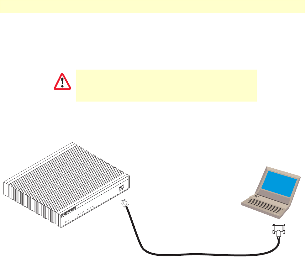
Introduction 125
OnSite 2800 Series User Manual C • Cabling
Introduction
This section provides information on the cables used to connect the OnSite to the existing network infrastruc-
ture and to third party products.
Serial console
The OnSite can be connected to a serial terminal over its serial console port, as depicted in figure 25.
Figure 25. Connecting a serial terminal
Note
See section “Console port, RJ-45, EIA-561 (RS-232)” on page 129
for console port pin-outs.
The interconnecting cables must be acceptable for external use
and must be rated for the proper application with respect to volt-
age, current, anticipated temperature, flammability, and
mechanical serviceability.
CAUTION
Link
100M
Activity
Enet 0
IPLink VPN Router
Run
Link
100M
Activity
Enet 1
Power
Console
Serial Terminal
Note A Patton Model 16F-561 RJ45 to DB-9 adapter is included with
each IPLink 2800 Series device
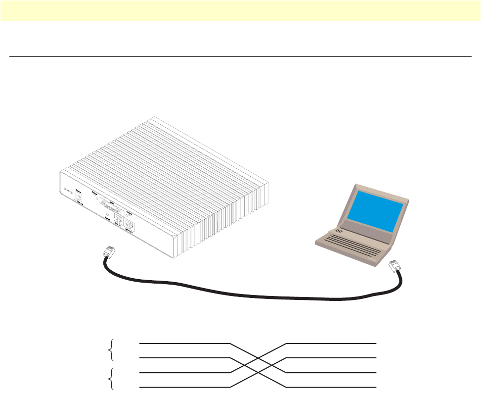
Ethernet 10Base-T and 100Base-T 126
OnSite 2800 Series User Manual C • Cabling
Ethernet 10Base-T and 100Base-T
Ethernet devices (10Base-T/100Base-T) are connected to the OnSite over a cable with RJ-45 plugs. Use a
cross-over cable to a host, or a straight cable to a hub. See figure 26 (host) and figure 27 on page 127 (hub) for
the different connections.
Figure 26. Ethernet cross-over
Host
Cross-over cable
RJ-45, male
Tx+
Tx-
Rx+
Rx-
1
2
3
6
RJ-45, male
1 TX+
2 TX-
3 RX+
6 RX-
Twisted pair 1
Twisted pair 2
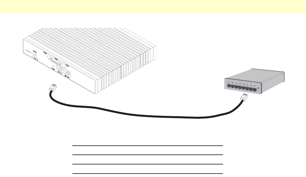
Ethernet 10Base-T and 100Base-T 127
OnSite 2800 Series User Manual C • Cabling
Figure 27. Ethernet straight-through
Hub
Straight-through cable
RJ-45, male
Tx+
Tx-
Rx+
Rx-
1
2
3
6
RJ-45, male
1 Rx+
2 Rx-
3 Tx+
6 Tx-

128
Appendix D Port pin-outs
Chapter contents
Introduction ........................................................................................................................................................129
Console port, RJ-45, EIA-561 (RS-232)............................................................................................................129
Ethernet 10Base-T and 100Base-T port.............................................................................................................130
Sync serial port...................................................................................................................................................130
V.35 serial port ............................................................................................................................................130
X.21 serial port ............................................................................................................................................131
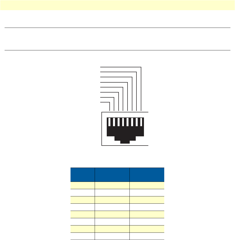
Introduction 129
OnSite 2800 Series User Manual D • Port pin-outs
Introduction
This section provides pin-out information for the ports of the OnSite router.
Console port, RJ-45, EIA-561 (RS-232)
The RS-232 serial console port of the OnSite is configured to operate as a DCE. View the image in figure 28
showing the RJ-45 receptacle with the numerical identification of the pin numbers and functions.
Figure 28. EIA-561 (RJ-45 8-pin) port
Refer to table 15 which tabulates the pin number, signal name and the direction of the signal.
Table 15. RS-232 Console Port
Pin No. Signal Name Signal
Direction
1DSR from OnSite
2CD from OnSite
3DTR to OnSite
4Signal Ground -
5RD from OnSite
6TD to OnSite
7CTS from OnSite
8RTS to OnSite
12345678
8–RTS
7–CTS
6–TD
5–RD
4–SG
3–DTR
2–CD
1–DSR
Ethernet 10Base-T and 100Base-T port 130
OnSite 2800 Series User Manual D • Port pin-outs
Ethernet 10Base-T and 100Base-T port
The Ethernet ports are auto-detect MDI-X.
Note
Pins not listed are not used.
Sync serial port
V. 3 5 s e r i a l po r t
Table 16. RJ-45 socket
Pin Signal Direction
1TX+ from OnSite
2TX- from OnSite
3RX+ to OnSite
6RX- to OnSite
Table 17. V.35 Female DB-25 connector
V.35 Interface Pin-Out
Pin Signal
1Frame Ground
2TD-a
3RD-a
4RTS
5CTS
6DSR
7Signal Ground
8DCD
9RC-b
11 ETC-b
12 TC-b
14 TD-b
15 RC-a
16 RD-b
17 RC-a
18 LL
20 DTR
21 RL
24 ETC-a

Sync serial port 131
OnSite 2800 Series User Manual D • Port pin-outs
X.21 serial port
Note
Pins not labeled are not used.
Table 18. X.21 Female DB-15 connector
X.21 Interface Pin-Out
Pin Signal
1Frame Ground
2TD-a
3CNTRL-a
4RD-a
5IND-a
6SET-a
8Signal Ground
9TD-b
10 CNTRL-b
11 RD-b
12 IND-b
13 SET-b


Introduction 133
OnSite 2800 Series User Manual E • OnSite 2800 Series factory configuration
Introduction
The factory configuration settings for the OnSite 2800 Series devices are as follows:
#----------------------------------------------------------------#
# 2800 Series
# R3.xx BUILDxxxxx
# 2005-01-18T00:00:00
# Factory configuration file
#----------------------------------------------------------------#
profile napt NAPT
profile dhcp-server DHCP
network 192.168.1.0 255.255.255.0
include 192.168.1.10 192.168.1.19
lease 2 hours
default-router 192.168.1.1
context ip router
interface eth0
ipaddress 172.16.40.1 255.255.0.0
use profile napt NAPT
interface eth1
ipaddress 192.168.1.1 255.255.255.0
context ip router
dhcp-server use DHCP
port ethernet 0 0
medium auto
encapsulation ip
bind interface eth0 router
no shutdown
port ethernet 0 1
medium auto
encapsulation ip
bind interface eth1 router
no shutdown


Introduction 135
OnSite 2800 Series User Manual F • Installation checklist
Introduction
This appendix lists the tasks for installing an OnSite 2800 Series Managed VPN Router (see table 19). Make a
copy of this checklist and mark the entries as you complete each task. For each OnSite 2800 Series Router,
include a copy of the completed checklist in your site log.
Table 19. Installation checklist
Task Verified by Date
Network information available & recorded in site log
Environmental specifications verified
Site power voltages verified
Installation site pre-power check completed
Required tools available
Additional equipment available
All printed documents available
OnSite release & build number verified
Rack, desktop, or wall mounting of chassis completed
Initial electrical connections established
ASCII terminal attached to console port
Cable length limits verified
Initial configuration performed
Initial operation verified
