Patton Electronic Rocketlink 3202 Users Manual SmartNode 4900 Series IpChannel Bank Getting Started Guide
2015-02-06
: Patton-Electronic Patton-Electronic-Rocketlink-3202-Users-Manual-517027 patton-electronic-rocketlink-3202-users-manual-517027 patton-electronic pdf
Open the PDF directly: View PDF ![]() .
.
Page Count: 106 [warning: Documents this large are best viewed by clicking the View PDF Link!]
- Summary Table of Contents
- Table of Contents
- List of Figures
- List of Tables
- About this guide
- Chapter 1 General information
- Chapter 2 Applications overview
- Chapter 3 Hardware installation
- Chapter 4 Web configuration
- Chapter 5 Console and Telnet configuration
- Chapter 6 Contacting Patton for assistance
- Appendix A Compliance information
- Appendix B Specifications
- Appendix C Port pin-outs

Patton Electronics Company, Inc.
7622 Rickenbacker Drive
Gaithersburg, MD 20879 USA
Tel: +1 (301) 975-1000
Fax: +1 (301) 869-9293
Support: +1 (301) 975-1007
Web: www.patton.com
E-mail: support@patton.com
Trademark Statement
The term
RocketLink
is a trademark of Patton Electronics Company. All other trade-
marks presented in this document are the property of their respective owners.
Copyright © 2009, Patton Electronics Company. All rights reserved.
The information in this document is subject to change without notice. Patton Elec-
tronics assumes no liability for errors that may appear in this document.
Warranty Information
Patton Electronics warrants all Model 3200 components to be free from defects, and
will—at our option—repair or replace the product should it fail within one year from
the first date of shipment.
This warranty is limited to defects in workmanship or materials, and does not cover
customer damage, abuse or unauthorized modification. If the product fails to perform
as warranted, your sole recourse shall be repair or replacement as described above.
Under no condition shall Patton Electronics be liable for any damages incurred by the
use of this product. These damages include, but are not limited to, the following: lost
profits, lost savings and incidental or consequential damages arising from the use of or
inability to use this product. Patton Electronics specifically disclaims all other warran-
ties, expressed or implied, and the installation or use of this product shall be deemed
an acceptance of these terms by the user.

3
Summary Table of Contents
1General information...................................................................................................................................... 17
2Applications overview.................................................................................................................................... 22
3Hardware installation.................................................................................................................................... 26
4Web configuration ........................................................................................................................................ 32
5Console and Telnet configuration................................................................................................................. 65
6Contacting Patton for assistance ................................................................................................................... 96
ACompliance information .............................................................................................................................. 99
BSpecifications .............................................................................................................................................. 101
CPort pin-outs .............................................................................................................................................. 104

4
Table of Contents
Summary Table of Contents ........................................................................................................................... 3
Table of Contents ........................................................................................................................................... 4
List of Figures ................................................................................................................................................. 9
List of Tables ................................................................................................................................................ 11
About this guide ........................................................................................................................................... 12
Audience............................................................................................................................................................... 12
Structure............................................................................................................................................................... 12
Precautions ........................................................................................................................................................... 13
Safety when working with electricity ...............................................................................................................14
Preventing Electrostatic Discharge Damage ....................................................................................................14
General observations .......................................................................................................................................15
Typographical conventions used in this document................................................................................................ 16
General conventions .......................................................................................................................................16
1General information...................................................................................................................................... 17
Model 3202 overview ............................................................................................................................................18
Model 3202 front panel.........................................................................................................................................19
LED descriptions ............................................................................................................................................19
Model 3202 rear panel...........................................................................................................................................20
Port descriptions .............................................................................................................................................20
Reset button ...................................................................................................................................................21
Ground terminal .............................................................................................................................................21
2Applications overview.................................................................................................................................... 22
Introduction..........................................................................................................................................................23
Typical application ................................................................................................................................................23
Distance charts ......................................................................................................................................................24
Distance Chart 3200 Series (Per Wire Pair) ....................................................................................................24
Distance Chart Model 3202/4W (4 Wire/2 Pair) ............................................................................................24
Distance Chart Model 3202/8W (8 Wire/4 Pair) ............................................................................................25
3Hardware installation.................................................................................................................................... 26
Introduction..........................................................................................................................................................27
Planning the installation........................................................................................................................................27
Network diagram ............................................................................................................................................28
IP related information .....................................................................................................................................28
AC Power Mains .............................................................................................................................................28
Location and mounting requirements .............................................................................................................29
Installing the Model 3202 .....................................................................................................................................29
Unpacking the Model 3202 ............................................................................................................................29
Connecting cables ...........................................................................................................................................29
Grounding the Model 3202 and connecting power .........................................................................................30

5
Model 3202 Getting Started Guide
Table of Contents
Configuring the Model 3202.................................................................................................................................31
Web configuration requirements .....................................................................................................................31
Console configuration requirements ................................................................................................................31
Telnet configuration requirements ..................................................................................................................31
4Web configuration ........................................................................................................................................ 32
Introduction..........................................................................................................................................................34
Setting Up the WMI .............................................................................................................................................34
TCP/IP setup ..................................................................................................................................................34
System Login ..................................................................................................................................................34
Basic Configuration Options .................................................................................................................................35
Operation mode and MGMT port .................................................................................................................35
DHCP server ..................................................................................................................................................36
LAN ...............................................................................................................................................................37
Review and save basic setup changes ...............................................................................................................38
Advanced Configuration Options..........................................................................................................................39
LINE ..............................................................................................................................................................39
Line Type ..................................................................................................................................................39
Annex Type ...............................................................................................................................................39
TCPAM Type ...........................................................................................................................................40
Main Rate .................................................................................................................................................40
SNR Margin .............................................................................................................................................40
Line Probe .................................................................................................................................................40
VLAN .............................................................................................................................................................41
802.1Q Tag-Based VLAN .........................................................................................................................43
Tag-Based VLAN Overview ................................................................................................................43
Configuring 802.1Q VLAN Tagging ..................................................................................................44
Port-Based VLAN .....................................................................................................................................46
Port-Based QinQ ......................................................................................................................................47
Quality of Service (QoS) .................................................................................................................................48
Port Based Priority ....................................................................................................................................49
VLAN Tag Priority ...................................................................................................................................50
WRR Scheduling Configuration Example ..........................................................................................51
IP DSCP Priority ......................................................................................................................................52
Differentiated Services Overview ........................................................................................................52
Configuring DSCP Options ...............................................................................................................54
Rate Control ...................................................................................................................................................55
Status Options.......................................................................................................................................................56
LINE Status ....................................................................................................................................................56
MGMT Status ................................................................................................................................................56
LAN Status .....................................................................................................................................................57
Administration Options.........................................................................................................................................57
Security Administration ..................................................................................................................................57
User Profiles ..............................................................................................................................................58

6
Model 3202 Getting Started Guide
Table of Contents
Remote Management Hosts ......................................................................................................................58
SNMP Administration ....................................................................................................................................59
Community Pool ......................................................................................................................................60
Trap Host Pool .........................................................................................................................................61
Utility Options......................................................................................................................................................61
System Information ........................................................................................................................................61
Configuration Tool .........................................................................................................................................62
Upgrade ..........................................................................................................................................................63
Logout ............................................................................................................................................................63
Restart ............................................................................................................................................................64
5Console and Telnet configuration................................................................................................................. 65
Introduction..........................................................................................................................................................67
Log in to the console interface .........................................................................................................................67
Log in using Telnet .........................................................................................................................................67
Interface commands ........................................................................................................................................67
Window structure ...........................................................................................................................................68
Main Menu Tree...................................................................................................................................................69
Menu tree for authorized users ........................................................................................................................69
Menu tree for unauthorized users ....................................................................................................................70
Enable Command Menu .......................................................................................................................................71
Setup Command Menu.........................................................................................................................................72
G.SHDSL .......................................................................................................................................................72
Mode ........................................................................................................................................................73
Link ..........................................................................................................................................................73
Annex Type ...............................................................................................................................................73
TCPAM Type ...........................................................................................................................................73
Maximum Main Rate ................................................................................................................................73
SNR Margin .............................................................................................................................................73
Line Probe .................................................................................................................................................74
Clear .........................................................................................................................................................74
LAN ...............................................................................................................................................................74
VLAN .............................................................................................................................................................75
Mode ........................................................................................................................................................75
802.1Q VLAN ...................................................................................................................................76
Port-Based VLAN ...............................................................................................................................77
QoS ................................................................................................................................................................78
Mode ........................................................................................................................................................78
Queue Weight ...........................................................................................................................................79
Queue Schedule ........................................................................................................................................79
Port-Based Priority QoS ............................................................................................................................80
VLAN Tag Priority QoS ...........................................................................................................................80
IP DSCP Priority QoS ..............................................................................................................................81
List ............................................................................................................................................................82

7
Model 3202 Getting Started Guide
Table of Contents
Rate ................................................................................................................................................................82
MGMT ..........................................................................................................................................................83
DHCP ............................................................................................................................................................83
DHCP Server ............................................................................................................................................84
DHCP Fixed Host ....................................................................................................................................84
DNS Proxy .....................................................................................................................................................85
Host Name .....................................................................................................................................................85
Factory Default ...............................................................................................................................................85
Status Command Menu ........................................................................................................................................86
G.SHDSL Status ............................................................................................................................................86
Interface Status ...............................................................................................................................................86
Show Command Menu .........................................................................................................................................87
Write Command ...................................................................................................................................................87
Reboot Command.................................................................................................................................................88
Ping Command .....................................................................................................................................................88
Administration Command Menu ..........................................................................................................................89
User Profile .....................................................................................................................................................89
Modify/Add User ......................................................................................................................................89
Security ...........................................................................................................................................................90
Telnet TCP Port .......................................................................................................................................90
Legal IP Address Pool ................................................................................................................................90
SNMP ............................................................................................................................................................91
Community ..............................................................................................................................................91
Trap host ..................................................................................................................................................92
Supervisor Password and ID ...........................................................................................................................93
Supervisor Password ..................................................................................................................................93
Supervisor ID ............................................................................................................................................93
Utility Command Menu........................................................................................................................................94
Upgrade main software ...................................................................................................................................94
Backup system configuration ..........................................................................................................................94
Restore system configuration ...........................................................................................................................94
Exit Command......................................................................................................................................................95
6Contacting Patton for assistance ................................................................................................................... 96
Introduction..........................................................................................................................................................97
Contact information..............................................................................................................................................97
Warranty Service and Returned Merchandise Authorizations (RMAs)...................................................................97
Warranty coverage ..........................................................................................................................................97
Out-of-warranty service .............................................................................................................................98
Returns for credit ......................................................................................................................................98
Return for credit policy .............................................................................................................................98
RMA numbers ................................................................................................................................................98
Shipping instructions ................................................................................................................................98
ACompliance information .............................................................................................................................. 99

8
Model 3202 Getting Started Guide
Table of Contents
Compliance .........................................................................................................................................................100
EMC compliance: .........................................................................................................................................100
Radio and TV interference (FCC Part 15)...........................................................................................................100
CE Declaration of Conformity ............................................................................................................................100
Authorized European Representative ...................................................................................................................100
BSpecifications .............................................................................................................................................. 101
G.SHDSL Connector..........................................................................................................................................102
G.SHDSL Specifications .....................................................................................................................................102
DSL Modulation .................................................................................................................................................102
Ethernet Connector.............................................................................................................................................102
LAN Protocols.....................................................................................................................................................102
VLAN Support....................................................................................................................................................102
QoS Support .......................................................................................................................................................102
Management Connector......................................................................................................................................102
Management Interface.........................................................................................................................................103
Front Panel Indicators .........................................................................................................................................103
Power Supply ......................................................................................................................................................103
Environment .......................................................................................................................................................103
Dimensions .........................................................................................................................................................103
Weight ................................................................................................................................................................103
CPort pin-outs .............................................................................................................................................. 104
Introduction........................................................................................................................................................105
Console port........................................................................................................................................................105
Ethernet ..............................................................................................................................................................106

9
List of Figures
1 Model 3202 . . . . . . . . . . . . . . . . . . . . . . . . . . . . . . . . . . . . . . . . . . . . . . . . . . . . . . . . . . . . . . . . . . . . . . . . . . . 18
2 Model 3202 front panel LEDs . . . . . . . . . . . . . . . . . . . . . . . . . . . . . . . . . . . . . . . . . . . . . . . . . . . . . . . . . . . . . 19
3 Model 3202 rear panel . . . . . . . . . . . . . . . . . . . . . . . . . . . . . . . . . . . . . . . . . . . . . . . . . . . . . . . . . . . . . . . . . . . 20
4 Model 3202 application . . . . . . . . . . . . . . . . . . . . . . . . . . . . . . . . . . . . . . . . . . . . . . . . . . . . . . . . . . . . . . . . . . 23
5 Model 3202 connection diagram . . . . . . . . . . . . . . . . . . . . . . . . . . . . . . . . . . . . . . . . . . . . . . . . . . . . . . . . . . . 28
6 Grounding stud . . . . . . . . . . . . . . . . . . . . . . . . . . . . . . . . . . . . . . . . . . . . . . . . . . . . . . . . . . . . . . . . . . . . . . . . 30
7 System login screen . . . . . . . . . . . . . . . . . . . . . . . . . . . . . . . . . . . . . . . . . . . . . . . . . . . . . . . . . . . . . . . . . . . . . . 34
8 Basic setup flowchart . . . . . . . . . . . . . . . . . . . . . . . . . . . . . . . . . . . . . . . . . . . . . . . . . . . . . . . . . . . . . . . . . . . . 35
9 Operation mode and MGMT port setup page . . . . . . . . . . . . . . . . . . . . . . . . . . . . . . . . . . . . . . . . . . . . . . . . . 35
10 Basic DHCP setup . . . . . . . . . . . . . . . . . . . . . . . . . . . . . . . . . . . . . . . . . . . . . . . . . . . . . . . . . . . . . . . . . . . . . . 37
11 LAN setup page . . . . . . . . . . . . . . . . . . . . . . . . . . . . . . . . . . . . . . . . . . . . . . . . . . . . . . . . . . . . . . . . . . . . . . . . 37
12 Review and save basic setup changes . . . . . . . . . . . . . . . . . . . . . . . . . . . . . . . . . . . . . . . . . . . . . . . . . . . . . . . . . 38
13 LINE page . . . . . . . . . . . . . . . . . . . . . . . . . . . . . . . . . . . . . . . . . . . . . . . . . . . . . . . . . . . . . . . . . . . . . . . . . . . . 39
14 VLAN page . . . . . . . . . . . . . . . . . . . . . . . . . . . . . . . . . . . . . . . . . . . . . . . . . . . . . . . . . . . . . . . . . . . . . . . . . . . . 41
15 VLAN Diagram . . . . . . . . . . . . . . . . . . . . . . . . . . . . . . . . . . . . . . . . . . . . . . . . . . . . . . . . . . . . . . . . . . . . . . . . 42
16 802.1Q Tag-Based VLAN page . . . . . . . . . . . . . . . . . . . . . . . . . . . . . . . . . . . . . . . . . . . . . . . . . . . . . . . . . . . . 43
17 VLAN tag field . . . . . . . . . . . . . . . . . . . . . . . . . . . . . . . . . . . . . . . . . . . . . . . . . . . . . . . . . . . . . . . . . . . . . . . . . 43
18 802.1Q VLAN diagram . . . . . . . . . . . . . . . . . . . . . . . . . . . . . . . . . . . . . . . . . . . . . . . . . . . . . . . . . . . . . . . . . . 44
19 Port-Based VLAN page . . . . . . . . . . . . . . . . . . . . . . . . . . . . . . . . . . . . . . . . . . . . . . . . . . . . . . . . . . . . . . . . . . . 46
20 Port-Based QinQ VLAN page . . . . . . . . . . . . . . . . . . . . . . . . . . . . . . . . . . . . . . . . . . . . . . . . . . . . . . . . . . . . . 47
21 VLAN Tag structure of an Ethernet frame . . . . . . . . . . . . . . . . . . . . . . . . . . . . . . . . . . . . . . . . . . . . . . . . . . . . 47
22 QoS page . . . . . . . . . . . . . . . . . . . . . . . . . . . . . . . . . . . . . . . . . . . . . . . . . . . . . . . . . . . . . . . . . . . . . . . . . . . . . 48
23 QoS - Port Based Priority page . . . . . . . . . . . . . . . . . . . . . . . . . . . . . . . . . . . . . . . . . . . . . . . . . . . . . . . . . . . . . 49
24 QoS - VLAN Tag Priority page . . . . . . . . . . . . . . . . . . . . . . . . . . . . . . . . . . . . . . . . . . . . . . . . . . . . . . . . . . . . 50
25 IEEE 802.1Q Tagged Frame for Ethernet . . . . . . . . . . . . . . . . . . . . . . . . . . . . . . . . . . . . . . . . . . . . . . . . . . . . 50
26 Service by WRR . . . . . . . . . . . . . . . . . . . . . . . . . . . . . . . . . . . . . . . . . . . . . . . . . . . . . . . . . . . . . . . . . . . . . . . . 52
27 Differentiated Services field . . . . . . . . . . . . . . . . . . . . . . . . . . . . . . . . . . . . . . . . . . . . . . . . . . . . . . . . . . . . . . . 52
28 QoS - IP DSCP Priority page . . . . . . . . . . . . . . . . . . . . . . . . . . . . . . . . . . . . . . . . . . . . . . . . . . . . . . . . . . . . . . 54
29 Rate Control page . . . . . . . . . . . . . . . . . . . . . . . . . . . . . . . . . . . . . . . . . . . . . . . . . . . . . . . . . . . . . . . . . . . . . . . 55
30 Rate Control options . . . . . . . . . . . . . . . . . . . . . . . . . . . . . . . . . . . . . . . . . . . . . . . . . . . . . . . . . . . . . . . . . . . . 55
31 LINE Status page (8-wire model shown) . . . . . . . . . . . . . . . . . . . . . . . . . . . . . . . . . . . . . . . . . . . . . . . . . . . . . . 56
32 MGMT Status page . . . . . . . . . . . . . . . . . . . . . . . . . . . . . . . . . . . . . . . . . . . . . . . . . . . . . . . . . . . . . . . . . . . . . 56
33 LAN Status page . . . . . . . . . . . . . . . . . . . . . . . . . . . . . . . . . . . . . . . . . . . . . . . . . . . . . . . . . . . . . . . . . . . . . . . . 57
34 Security Administration page . . . . . . . . . . . . . . . . . . . . . . . . . . . . . . . . . . . . . . . . . . . . . . . . . . . . . . . . . . . . . . 57
35 Model 3202 configuration modes . . . . . . . . . . . . . . . . . . . . . . . . . . . . . . . . . . . . . . . . . . . . . . . . . . . . . . . . . . . 58
36 Remote Management Host section . . . . . . . . . . . . . . . . . . . . . . . . . . . . . . . . . . . . . . . . . . . . . . . . . . . . . . . . . . 58
37 SNMP Administration page . . . . . . . . . . . . . . . . . . . . . . . . . . . . . . . . . . . . . . . . . . . . . . . . . . . . . . . . . . . . . . . 59
38 SNMP community pool configuration . . . . . . . . . . . . . . . . . . . . . . . . . . . . . . . . . . . . . . . . . . . . . . . . . . . . . . . 60
39 Trap host pool configuration . . . . . . . . . . . . . . . . . . . . . . . . . . . . . . . . . . . . . . . . . . . . . . . . . . . . . . . . . . . . . . 61
40 System Information page . . . . . . . . . . . . . . . . . . . . . . . . . . . . . . . . . . . . . . . . . . . . . . . . . . . . . . . . . . . . . . . . . 61
41 Configuration Tool page . . . . . . . . . . . . . . . . . . . . . . . . . . . . . . . . . . . . . . . . . . . . . . . . . . . . . . . . . . . . . . . . . 62
42 Upgrade page . . . . . . . . . . . . . . . . . . . . . . . . . . . . . . . . . . . . . . . . . . . . . . . . . . . . . . . . . . . . . . . . . . . . . . . . . . 63
43 Logout page . . . . . . . . . . . . . . . . . . . . . . . . . . . . . . . . . . . . . . . . . . . . . . . . . . . . . . . . . . . . . . . . . . . . . . . . . . . 63
44 Restart page . . . . . . . . . . . . . . . . . . . . . . . . . . . . . . . . . . . . . . . . . . . . . . . . . . . . . . . . . . . . . . . . . . . . . . . . . . . 64
45 Restart page . . . . . . . . . . . . . . . . . . . . . . . . . . . . . . . . . . . . . . . . . . . . . . . . . . . . . . . . . . . . . . . . . . . . . . . . . . . 64
46 Console/Telnet Menu . . . . . . . . . . . . . . . . . . . . . . . . . . . . . . . . . . . . . . . . . . . . . . . . . . . . . . . . . . . . . . . . . . . . 68
47 Menu tree for authorized users . . . . . . . . . . . . . . . . . . . . . . . . . . . . . . . . . . . . . . . . . . . . . . . . . . . . . . . . . . . . . 69

10
Model 3202 Getting Started Guide
48 Main screen for authorized users . . . . . . . . . . . . . . . . . . . . . . . . . . . . . . . . . . . . . . . . . . . . . . . . . . . . . . . . . . . . 70
49 Main menu for unauthorized users . . . . . . . . . . . . . . . . . . . . . . . . . . . . . . . . . . . . . . . . . . . . . . . . . . . . . . . . . . 70
50 Main screen for unauthorized users . . . . . . . . . . . . . . . . . . . . . . . . . . . . . . . . . . . . . . . . . . . . . . . . . . . . . . . . . . 70
51 G.SHDSL Status . . . . . . . . . . . . . . . . . . . . . . . . . . . . . . . . . . . . . . . . . . . . . . . . . . . . . . . . . . . . . . . . . . . . . . . 86
52 Interface Status . . . . . . . . . . . . . . . . . . . . . . . . . . . . . . . . . . . . . . . . . . . . . . . . . . . . . . . . . . . . . . . . . . . . . . . . . 86
53 System Information . . . . . . . . . . . . . . . . . . . . . . . . . . . . . . . . . . . . . . . . . . . . . . . . . . . . . . . . . . . . . . . . . . . . . 87
54 EIA-561 (RJ-45 8-pin) port . . . . . . . . . . . . . . . . . . . . . . . . . . . . . . . . . . . . . . . . . . . . . . . . . . . . . . . . . . . . . . 105

11
List of Tables
1 General conventions . . . . . . . . . . . . . . . . . . . . . . . . . . . . . . . . . . . . . . . . . . . . . . . . . . . . . . . . . . . . . . . . . . . . . 16
2 Front panel LEDs . . . . . . . . . . . . . . . . . . . . . . . . . . . . . . . . . . . . . . . . . . . . . . . . . . . . . . . . . . . . . . . . . . . . . . . 19
3 Port descriptions . . . . . . . . . . . . . . . . . . . . . . . . . . . . . . . . . . . . . . . . . . . . . . . . . . . . . . . . . . . . . . . . . . . . . . . . 20
4 Distance Chart 3202 Series (Per Wire Pair) . . . . . . . . . . . . . . . . . . . . . . . . . . . . . . . . . . . . . . . . . . . . . . . . . . . 24
5 Distance Chart Model 3202/4W (4 Wire/2 Pair) . . . . . . . . . . . . . . . . . . . . . . . . . . . . . . . . . . . . . . . . . . . . . . . 24
6 Distance Chart Model 3202/8W (8 Wire/4 Pair) . . . . . . . . . . . . . . . . . . . . . . . . . . . . . . . . . . . . . . . . . . . . . . . 25
7 Line Type Chart . . . . . . . . . . . . . . . . . . . . . . . . . . . . . . . . . . . . . . . . . . . . . . . . . . . . . . . . . . . . . . . . . . . . . . . . 39
8 Main Rate Chart . . . . . . . . . . . . . . . . . . . . . . . . . . . . . . . . . . . . . . . . . . . . . . . . . . . . . . . . . . . . . . . . . . . . . . . . 40
9 Reserved Protocol Values . . . . . . . . . . . . . . . . . . . . . . . . . . . . . . . . . . . . . . . . . . . . . . . . . . . . . . . . . . . . . . . . . 48
10 WRR Scheduling Configuration Example Values . . . . . . . . . . . . . . . . . . . . . . . . . . . . . . . . . . . . . . . . . . . . . . . 51
11 VLAN Tag Priority Levels . . . . . . . . . . . . . . . . . . . . . . . . . . . . . . . . . . . . . . . . . . . . . . . . . . . . . . . . . . . . . . . . 51
12 Bits in the DSCP field . . . . . . . . . . . . . . . . . . . . . . . . . . . . . . . . . . . . . . . . . . . . . . . . . . . . . . . . . . . . . . . . . . . 53
13 DSCP Coding . . . . . . . . . . . . . . . . . . . . . . . . . . . . . . . . . . . . . . . . . . . . . . . . . . . . . . . . . . . . . . . . . . . . . . . . . 53
14 Default SNMP Communities . . . . . . . . . . . . . . . . . . . . . . . . . . . . . . . . . . . . . . . . . . . . . . . . . . . . . . . . . . . . . . 60
15 Console settings . . . . . . . . . . . . . . . . . . . . . . . . . . . . . . . . . . . . . . . . . . . . . . . . . . . . . . . . . . . . . . . . . . . . . . . . 67
16 Interface commands . . . . . . . . . . . . . . . . . . . . . . . . . . . . . . . . . . . . . . . . . . . . . . . . . . . . . . . . . . . . . . . . . . . . . 67
17 Enable Command Menu . . . . . . . . . . . . . . . . . . . . . . . . . . . . . . . . . . . . . . . . . . . . . . . . . . . . . . . . . . . . . . . . . 71
18 G.SHDSL Options . . . . . . . . . . . . . . . . . . . . . . . . . . . . . . . . . . . . . . . . . . . . . . . . . . . . . . . . . . . . . . . . . . . . . . 72
19 Line Type Chart . . . . . . . . . . . . . . . . . . . . . . . . . . . . . . . . . . . . . . . . . . . . . . . . . . . . . . . . . . . . . . . . . . . . . . . . 73
20 Main Rate Chart . . . . . . . . . . . . . . . . . . . . . . . . . . . . . . . . . . . . . . . . . . . . . . . . . . . . . . . . . . . . . . . . . . . . . . . . 73
21 LAN Options . . . . . . . . . . . . . . . . . . . . . . . . . . . . . . . . . . . . . . . . . . . . . . . . . . . . . . . . . . . . . . . . . . . . . . . . . . 74
22 VLAN Mode Options . . . . . . . . . . . . . . . . . . . . . . . . . . . . . . . . . . . . . . . . . . . . . . . . . . . . . . . . . . . . . . . . . . . . 75
23 802.1Q VLAN Options . . . . . . . . . . . . . . . . . . . . . . . . . . . . . . . . . . . . . . . . . . . . . . . . . . . . . . . . . . . . . . . . . . 77
24 VLAN Mode Options . . . . . . . . . . . . . . . . . . . . . . . . . . . . . . . . . . . . . . . . . . . . . . . . . . . . . . . . . . . . . . . . . . . . 78
25 Queue Weight Options . . . . . . . . . . . . . . . . . . . . . . . . . . . . . . . . . . . . . . . . . . . . . . . . . . . . . . . . . . . . . . . . . . 79
26 Queue Schedule Types . . . . . . . . . . . . . . . . . . . . . . . . . . . . . . . . . . . . . . . . . . . . . . . . . . . . . . . . . . . . . . . . . . . 79
27 Queue Schedule Options . . . . . . . . . . . . . . . . . . . . . . . . . . . . . . . . . . . . . . . . . . . . . . . . . . . . . . . . . . . . . . . . . 80
28 Port-Based Priority QoS Options . . . . . . . . . . . . . . . . . . . . . . . . . . . . . . . . . . . . . . . . . . . . . . . . . . . . . . . . . . . 80
29 VLAN Tag Priority QoS Options . . . . . . . . . . . . . . . . . . . . . . . . . . . . . . . . . . . . . . . . . . . . . . . . . . . . . . . . . . . 81
30 VLAN Tag Priority Levels . . . . . . . . . . . . . . . . . . . . . . . . . . . . . . . . . . . . . . . . . . . . . . . . . . . . . . . . . . . . . . . . 81
31 Rate Options . . . . . . . . . . . . . . . . . . . . . . . . . . . . . . . . . . . . . . . . . . . . . . . . . . . . . . . . . . . . . . . . . . . . . . . . . . 82
32 IP DSCP Priority QoS Options . . . . . . . . . . . . . . . . . . . . . . . . . . . . . . . . . . . . . . . . . . . . . . . . . . . . . . . . . . . . 82
33 Status Command Menu . . . . . . . . . . . . . . . . . . . . . . . . . . . . . . . . . . . . . . . . . . . . . . . . . . . . . . . . . . . . . . . . . . 86
34 Show Command Menu . . . . . . . . . . . . . . . . . . . . . . . . . . . . . . . . . . . . . . . . . . . . . . . . . . . . . . . . . . . . . . . . . . 87
35 RJ45 socket 10/100Base-T . . . . . . . . . . . . . . . . . . . . . . . . . . . . . . . . . . . . . . . . . . . . . . . . . . . . . . . . . . . . . . . 106
36 RJ45 socket 1000Base-T . . . . . . . . . . . . . . . . . . . . . . . . . . . . . . . . . . . . . . . . . . . . . . . . . . . . . . . . . . . . . . . . . 106

12
About this guide
This guide describes the RocketLink™ Model 3202 hardware, installation and basic configuration.
Audience
This guide is intended for the following users:
•Operators
•Installers
•Maintenance technicians
Structure
This guide contains the following chapters and appendices:
•Chapter 1, “General information” on page 17 provides information about modem features and capabilities
•Chapter 2, “Applications overview” on page 22 describes the typical application for the Model 3202
•Chapter 3, “Hardware installation” on page 26 provides quick start hardware installation procedures
•Chapter 4, “Web configuration” on page 32 describes configuring the Model 3202 via the web interface
•Chapter 5, “Console and Telnet configuration” on page 65 describes configuring the Model 3202 via the
console interface
•Chapter 6, “Contacting Patton for assistance” on page 96 contains information on contacting Patton tech-
nical support for assistance
•Appendix A, “Compliance information” on page 99 contains compliance information for the Model 3202
•Appendix B, “Specifications” on page 101 contains for the specifications for the Model 3202
•Appendix C, “Port pin-outs” on page 104 contains pinouts for the Model 3202 ports
For best results, read the contents of this guide before you install the Model 3202.
13
Model 3202 Getting Started Guide
About this guide
Precautions
Notes, cautions, and warnings, which have the following meanings, are used throughout this guide to help you
become aware of potential problems.
Warnings
are intended to prevent safety hazards that could result in per-
sonal injury.
Cautions
are intended to prevent situations that could result in property damage or
impaired functioning.
Note
A note presents additional information or interesting sidelights.
The alert symbol and IMPORTANT heading calls attention to
important information.
The alert symbol and CAUTION heading indicate a potential
hazard. Strictly follow the instructions to avoid
property damage.
The shock hazard symbol and CAUTION heading indicate a
potential electric shock hazard. Strictly follow the instructions to
avoid property damage caused by electric shock.
The alert symbol and WARNING heading indicate a potential safety hazard.
Strictly follow the warning instructions to avoid personal injury.
The shock hazard symbol and WARNING heading indicate a potential electric
shock hazard. Strictly follow the warning instructions to avoid injury caused
by electric shock.
IMPORTANT
CAUTION
CAUTION
WARNING
WARNING
14
Model 3202 Getting Started Guide
About this guide
Safety when working with electricity
Preventing Electrostatic Discharge Damage
When starting to install interface cards place the interface card on its shielded plastic bag if you lay it on
your bench.
Electrostatic Discharge (ESD) can damage equipment and impair electrical circuitry. It occurs when electronic
The Model 3202 contains no user serviceable parts. The equipment shall be
returned to Patton Electronics for repairs, or repaired by qualified service per-
sonnel. Opening the Model 3202 case will void the warranty.
Mains Voltage: Do not open the case the when the power cord is attached.
Line voltages are present within the power supply when the power cords are
connected. The mains outlet that is utilized to power the device shall be
within 10 feet (3 meters) of the device, shall be easily accessible, and pro-
tected by a circuit breaker.
For AC powered units, ensure that the power cable used meets all applicable
standards for the country in which it is to be installed, and that it is connected
to a wall outlet which has earth ground.
Hazardous network voltages are present in WAN ports regardless of whether
power to the Model 3202 is ON or OFF. To avoid electric shock, use caution
when near WAN ports. When detaching the cables, detach the end away from
the Model 3202 first.
Do not work on the system or connect or disconnect cables during periods of
lightning activity.
In accordance with the requirements of council directive 2002/
96/EC on Waste of Electrical and Electronic Equipment (WEEE),
ensure that at end-of-life you separate this product from other
waste and scrap and deliver to the WEEE collection system in
your country for recycling.
WARNING
WARNING
WARNING
WARNING
WARNING

15
Model 3202 Getting Started Guide
About this guide
printed circuit cards are improperly handled and can result in complete or intermittent failures.
General observations
•C
lean the case with a soft slightly moist anti-static cloth
•Place the unit on a flat surface and ensure free air circulation
•Avoid exposing the unit to direct sunlight and other heat sources
•
Protect the unit from moisture, vapors, and corrosive liquid
s
Always follow ESD prevention procedures when removing and
replacing cards.
Wear an ESD-preventive wrist strap, ensuring that it makes good
skin contact. Connect the clip to an unpainted surface of the
chassis frame to safely channel unwanted ESD voltages
to ground.
To properly guard against ESD damage and shocks, the wrist
strap and cord must operate effectively. If no wrist strap is avail-
able, ground yourself by touching the metal part of the chassis.
CAUTION
16
Model 3202 Getting Started Guide
About this guide
Typographical conventions used in this document
This section describes the typographical conventions and terms used in this guide.
General conventions
The procedures described in this manual use the following text conventions:
Table 1. General conventions
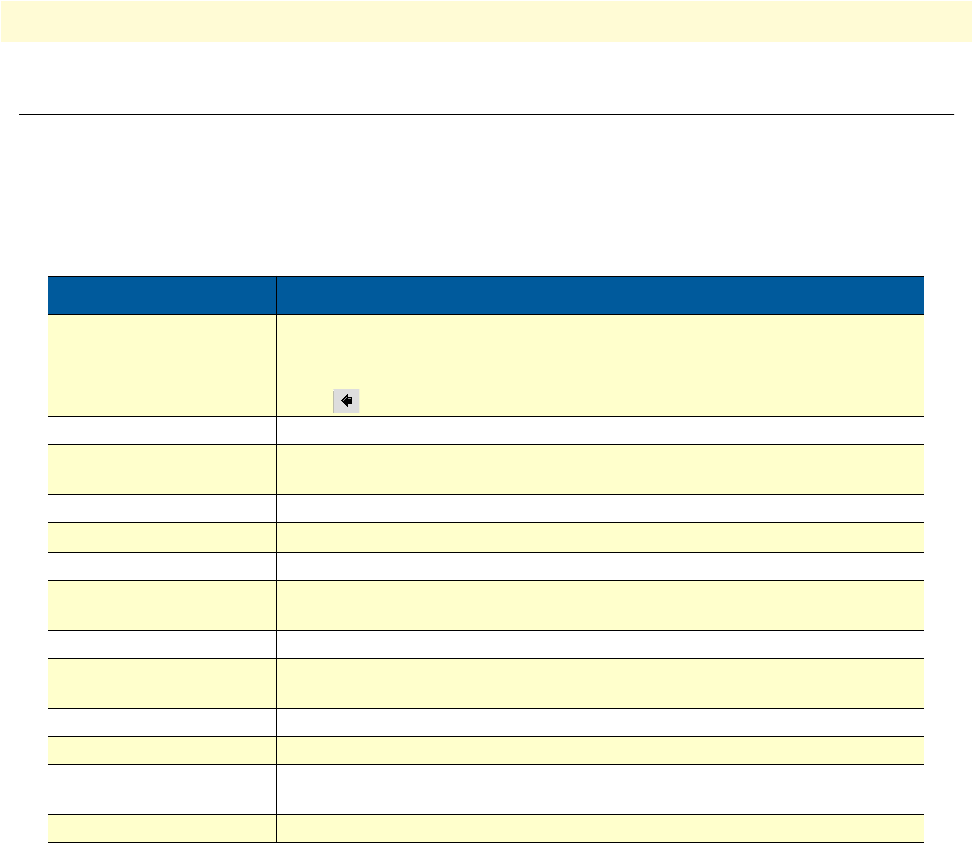
Convention Meaning
Garamond blue type
Indicates a cross-reference hyperlink that points to a figure, graphic, table, or sec-
tion heading. Clicking on the hyperlink jumps you to the reference. When you
have finished reviewing the reference, click on the
Go to Previous View
button in the Adobe® Acrobat® Reader toolbar to return to your starting point.
Futura bold type Commands and keywords are in
boldface
font.
Futura bold-italic type Parts of commands, which are related to elements already named by the user, are
in
boldface italic
font.
Italicized Futura type
Variables for which you supply values are in
italic
font
Futura type
Indicates the names of fields or windows.
Garamond bold type Indicates the names of command buttons that execute an action.
< >
Angle brackets indicate function and keyboard keys, such as <SHIFT>, <CTRL>,
<C>, and so on.
[ ] Elements in square brackets are optional.
{a | b | c} Alternative but required keywords are grouped in braces ({ }) and are separated
by vertical bars ( | )
blue screen Information you enter is in
blue screen
font.
screen Terminal sessions and information the system displays are in
screen font
.
node The leading IP address or nodename of a Model 3202 is substituted with
node
in
boldface italic
font.
# An hash sign at the beginning of a line indicates a comment line.

17
Chapter 1
General information
Chapter contents
Model 3202 overview ............................................................................................................................................18
Model 3202 front panel.........................................................................................................................................19
LED descriptions ............................................................................................................................................19
Model 3202 rear panel...........................................................................................................................................20
Port descriptions .............................................................................................................................................20
Reset button ...................................................................................................................................................21
Ground terminal .............................................................................................................................................21
Model 3202 overview
18
Model 3202 Getting Started Guide
1 • General information
Model 3202 overview
The Patton RocketLink™ Model 3202 simplifies and provides cost effective network extension by utilizing
pre-existing twisted pair infrastructure enables service providers to offer broadband or data backhaul services to
businesses, governments, and various institutions over existing last-mile, copper infrastructure. Today, more
than ever, operators are finding the business case for leveraging their existing copper networks to be highly
attractive from an ROI and initial investment perspective over fiber roll-outs.
The Model 3202 is Ethernet First Mile (EFM) compliant. EFM—also called pure Ethernet—lowers OPEX
and CAPEX by resolving one of the biggest deficiencies in carrier networks, the lack of interworking arrange-
ments among different protocols such as Frame Relay, TDM, ATM, and of course DSL. Using EFM allows for
more efficient and trouble-free networking environments. Service providers can concentrate on providing dif-
ferentiated services instead of concentrating on resolving their latest issue of protocol conversions.
Patton’s 3202 G.SHDSL.bis modem incorporates next-generation G.SHDSL technology with multi-pair
bonding to offer unmatched rate, reach and reliable Ethernet connectivity, providing symmetrical 22.8 Mbps
of bandwidth over 4-pair (8-wire) at distances up to 1.8 miles (2.9 km). The Model 3202 comes standard with
a 4-port fast Ethernet switch with full QoS and CoS features. VLAN (802.1q) capabilities include 4 levels of
priorities, traffic flow control, and rate control. These traffic management and QoS features enable service pro-
viders to provision for differentiated services and/or SLAs.
The Model 3202 is a complete, managed, end-to-end system when used either back-to-back or with a 3rd
party ipDSLAM. The 3202 is the clear and easy choice for mission-critical networking.
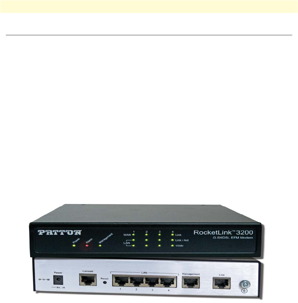
Figure 1. Model 3202
The following base models are available:
•3202/2W/EUI: G.SHDSL 2Base-TL EFM Modem (2-wire), 5.7 Mbps
•3202/4W/EUI: G.SHDSL 2Base-TL EFM Modem (4-wire), 11.4 Mbps
•3202/8W/EUI: G.SHDSL 2Base-TL EFM Modem (8-wire), 22.8 Mbps
Refer to Appendix B, “Specifications” on page 101 for a complete feature description of the Model 3202.
Model 3202 front panel
19
Model 3202 Getting Started Guide
1 • General information
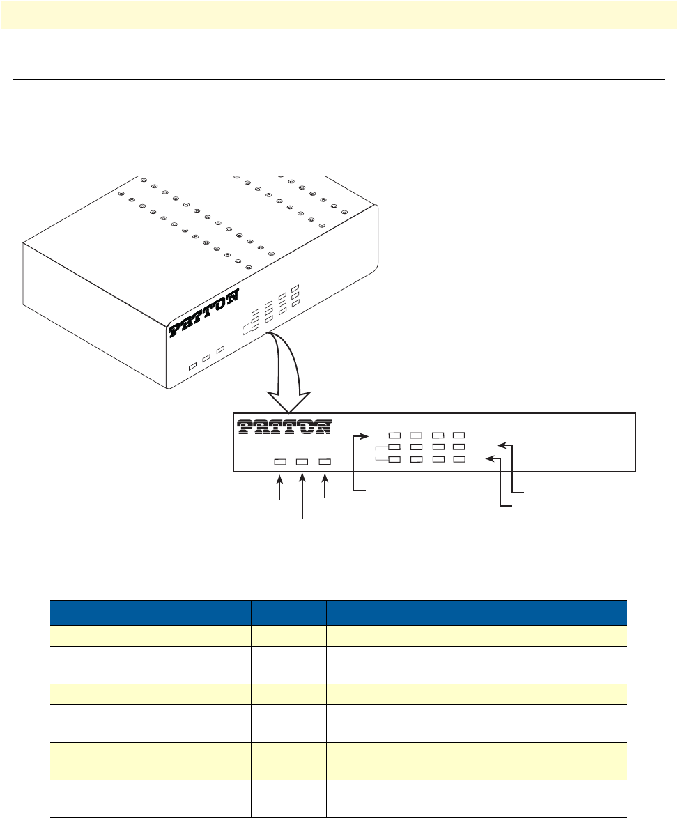
Model 3202 front panel
LED descriptions
The front panel LEDs display the status of the power, system, Ethernet ports, and Line port. Figure 2 shows
the front panel LED indicators and table 2 provides a description of the LED indicators’ behavior.
Figure 2. Model 3202 front panel LEDs
Table 2. Front panel LEDs
LED Condition Description
PWR On Power is applied
ALM On
Blink
DSL LINE connection dropped
DSL LINE self-test
DIAG On Management port is connected
WAN (1-4) LINK On
Blink
DSL LINE is connected
DSL LINE handshake/transmitted/received data
LAN (1-4) LINK/ACT On
Blink
Ethernet is connected
Ethernet link transmitted/received data
LAN (1-4)100M On
Off
LAN port is on 100M mode
LAN port is on 10M mode
Power
RocketLink™ 3200
G.SHDSL EFM Modem
PWR ALM DIAG
WAN
LAN 100M
LINK/ACT
LINK
1 2 3 4
PWRALM DIAG
WAN
LAN 100M
LINK/ACT
LINK
1 2 3 4
RocketLink™ 3200
G.SHDSL EFM Modem
Alarm
Console
WAN(1-4) Line Connection LAN (1-4) Ethernet Link/Activity
LAN (1-4) Ethernet Mode
Model 3202 rear panel 20
Model 3202 Getting Started Guide 1 • General information
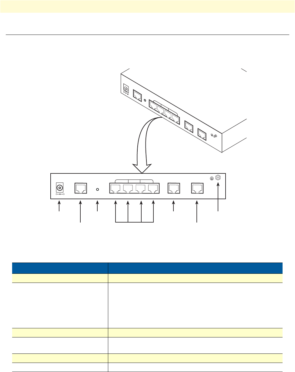
Model 3202 rear panel
Port descriptions
The RocketLink™ Model 3202 rear panel ports are shown in figure 3 and described in table 3.
Figure 3. Model 3202 rear panel
Note For port pinout information, see Appendix C, “Port pin-outs” on
page 104.
Table 3. Port descriptions
Port Description
DC 9V 2A Power adaptor inlet: Input voltage 9VDC 2A
Console (RS-232 control port) Used for service and maintenance, the Console port, an RS-232
RJ-45 connector with EIA-561 pinout, connects the router to a
serial terminal such as a PC or ASCII terminal (also called a dumb
terminal). Asynchronous default data rate 9600 bps, hardware
DSR and DTR signals for external modems are wired directly
together internally
RST Reset button for rebooting or loading factory default settings
LAN (LAN Ethernet Ports 1-4) 10/100Base-Tx full-/half-duplex, RJ-45, auto detection and fall-
back, connects the unit to an Ethernet LAN.
MGMT RJ-45 for management port
LINE G.SHDSL .Bis interface for WAN port (RJ-45)
+-
RST
DC 9V
LAN
MGMT LINE
CONSOLE
1 2 3 4
DC 9V CONSOLE
RST
MGMT LINE
LAN
Power
Console
RS-232 port
Reset button
LAN (1-4)
RJ-45 port
1 2 3 4
Management
RJ-45 port
DSL
RJ-45 port
Ground

Model 3202 rear panel 21
Model 3202 Getting Started Guide 1 • General information
Reset button
•To restart the unit with the current startup configuration—Press for less than 1 second and release the Reset
button. The Model 3202 will restart with the current startup configuration.
•To restart the unit with factory default configuration—Press the Reset button for 5 seconds until the Power
LED starts blinking. The unit will restart with factory default configuration.
•To restart the unit in bootloader mode (to be used only by trained RocketLink technicians)—Start with the
unit powered off. Press and hold the Reset button while applying power to the unit. Release the Reset button
when the Power LED starts blinking so the unit will enter bootloader mode.
Ground terminal
The marked lug or terminal should be connected to the building protective earth bus.The func-
tion of protective earth does not serve the purpose of providing protection against electrical shock,
but instead enhances surge suppression on the DSL lines for installations where suitable bonding
facilities exist.The connector type is M3 machine screw.

22
Chapter 2 Applications overview
Chapter contents
Introduction..........................................................................................................................................................23
Typical application ................................................................................................................................................23
Distance charts ......................................................................................................................................................24
Distance Chart 3200 Series (Per Wire Pair) ....................................................................................................24
Distance Chart Model 3202/4W (4 Wire/2 Pair) ............................................................................................24
Distance Chart Model 3202/8W (8 Wire/4 Pair) ............................................................................................25
Introduction 23
Model 3202 Getting Started Guide 2 • Applications overview
Introduction
The Model 3202 is Ethernet First Mile (EFM) compliant. EFM—also called pure Ethernet—lowers OPEX
and CAPEX by resolving one of the biggest deficiencies in carrier networks, the lack of interworking arrange-
ments among different protocols such as Frame Relay, TDM, ATM, and of course DSL. Using EFM allows for
more efficient and trouble-free networking environments. Service providers can concentrate on providing dif-
ferentiated services instead of concentrating on resolving their latest issue of protocol conversions.
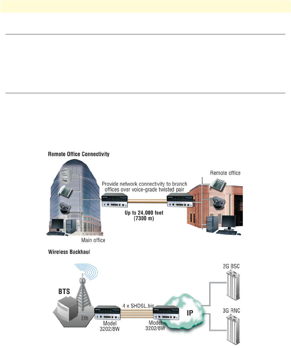
Typical application
The Model 3202 G.SHDSL EFM modems are ideal for delivering remote network access for inter-office con-
nectivity. Businesses can take advantage of the already installed copper infrastructure and pass up to 22.8 Mbps
of symmetrical data reliably at distances of up to 1.8 miles (2.9 km).
Utilize pre-existing copper infrastructure for mobile backhaul to reduce Last Mile transport costs and to con-
nect to new packet-switched networks.
Figure 4. Model 3202 application
Distance charts 24
Model 3202 Getting Started Guide 2 • Applications overview
Distance charts
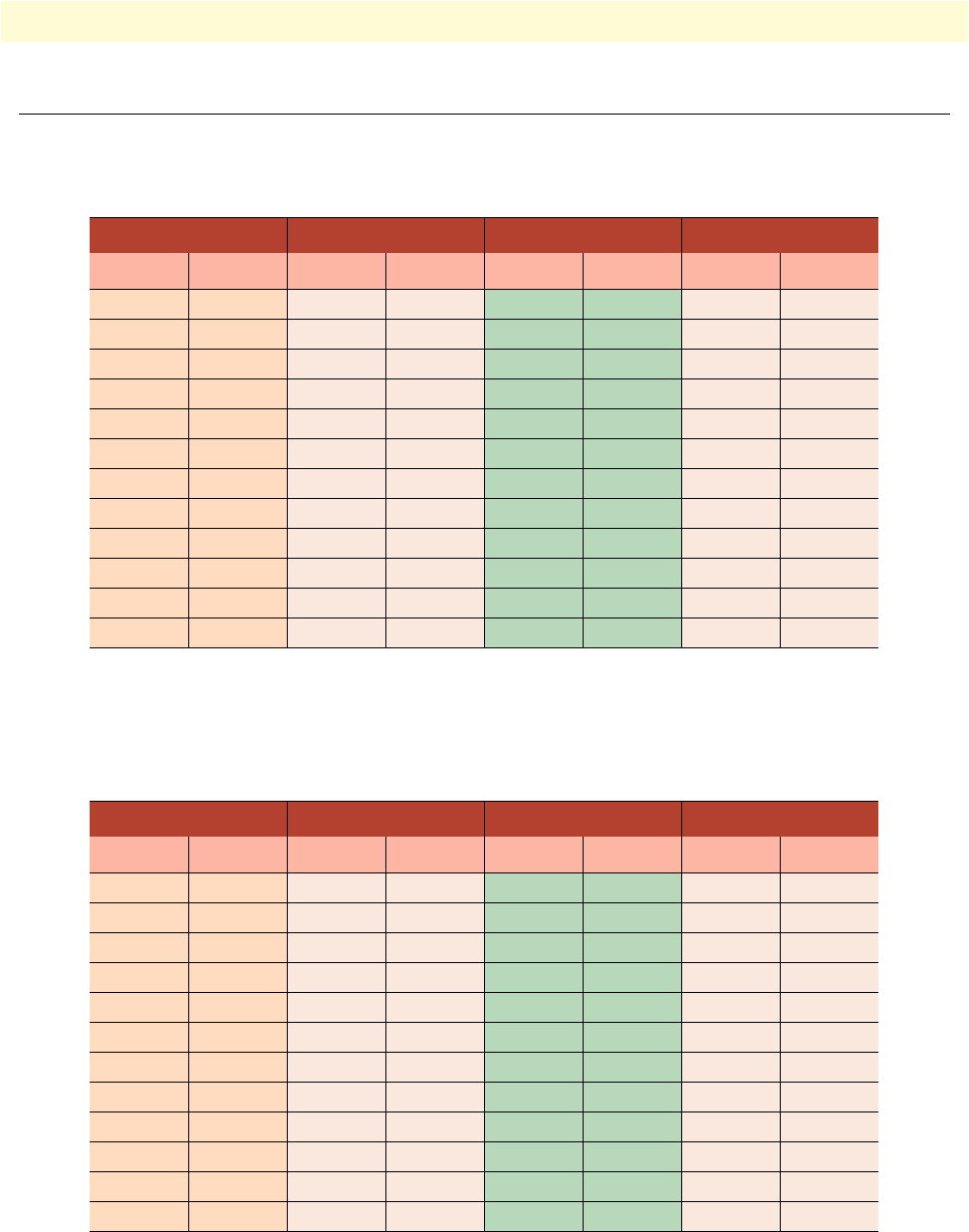
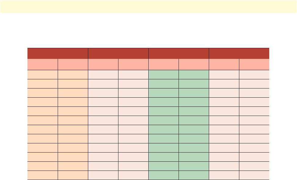
Distance Chart 3200 Series (Per Wire Pair)
Distance Chart Model 3202/4W (4 Wire/2 Pair)
Table 4. Distance Chart 3202 Series (Per Wire Pair)
DSL Line Rate 26 AWG/0.4mm 24 AWG/0.5mm 22 AWG/0.65mm
N kbps kft km kft km kft km
3 192 21.5 6.6 27.2 8.3 34.8 10.6
4 256 19.5 5.9 24.7 7.5 31.5 9.6
8 512 17.5 5.3 22.1 6.7 28.3 8.6
12 768 16.5 5 20.9 6.4 26.7 8.1
16 1024 16 4.9 20.2 6.2 25.9 7.9
20 1280 15 4.6 19 5.8 24.3 7.4
24 1536 14.5 4.4 18.3 5.6 23.5 7.2
32 2048 13.5 4.1 17.1 5.2 21.8 6.6
36 2304 13 4 16.4 5 21 6.4
60 3840 10 3 12.6 3.8 16.2 4.9
72 4608 9.5 2.9 12 3.7 15.4 4.7
89 5696 8.5 2.6 10.8 3.3 13.8 4.2
Table 5. Distance Chart Model 3202/4W (4 Wire/2 Pair)
DSL Line Rate 26 AWG/0.4mm 24 AWG/0.5mm 22 AWG/0.65mm
N kbps kft km kft km kft km
6 512 19.5 5.9 24.7 7.5 31.5 9.6
8 512 19.5 5.9 24.7 7.5 31.5 9.6
16 1024 17.5 5.3 22.1 6.7 28.3 8.6
24 1536 16.5 5 20.9 6.4 26.7 8.1
32 2048 16 4.9 20.2 6.2 25.9 7.9
40 2560 15 4.6 19 5.8 24.3 7.4
48 3072 14.5 4.4 18.3 5.6 23.5 7.2
64 4096 13.5 4.1 17.1 5.2 21.8 6.6
72 4608 13 4 16.4 5 21 6.4
120 7680 10 3 12.6 3.8 16.2 4.9
144 9216 9.5 2.9 12 3.7 15.4 4.7
178 11392 8.5 2.6 10.8 3.3 13.8 4.2
Distance charts 25
Model 3202 Getting Started Guide 2 • Applications overview
Distance Chart Model 3202/8W (8 Wire/4 Pair)
Table 6. Distance Chart Model 3202/8W (8 Wire/4 Pair)
DSL Line Rate 26 AWG/0.4mm 24 AWG/0.5mm 22 AWG/0.65mm
N kbps kft km kft km kft km
12 768 21.5 6.6 27.2 8.3 34.8 10.6
16 1024 19.5 5.9 24.7 7.5 31.5 9.6
32 2048 17.5 5.3 22.1 6.7 28.3 8.6
48 3072 16.5 5 20.9 6.4 26.7 8.1
64 4096 16 4.9 20.2 6.2 25.9 7.9
80 5120 15 4.6 19 5.8 24.3 7.4
96 6144 14.5 4.4 18.3 5.6 23.5 7.2
128 8192 13.5 4.1 17.1 5.2 21.8 6.6
144 9216 13 4 16.4 5 21 6.4
240 15360 10 3 12.6 3.8 16.2 4.9
288 18432 9.5 2.9 12 3.7 15.4 4.7
356 22784 8.5 2.6 10.8 3.3 13.8 4.2

26
Chapter 3 Hardware installation
Chapter contents
Introduction..........................................................................................................................................................27
Planning the installation........................................................................................................................................27
Network diagram ............................................................................................................................................28
IP related information .....................................................................................................................................28
AC Power Mains .............................................................................................................................................28
Location and mounting requirements .............................................................................................................29
Installing the Model 3202 .....................................................................................................................................29
Unpacking the Model 3202 ............................................................................................................................29
Connecting cables ...........................................................................................................................................29
Grounding the Model 3202 and connecting power .........................................................................................30
Configuring the Model 3202.................................................................................................................................31
Web configuration requirements .....................................................................................................................31
Console configuration requirements ................................................................................................................31
Telnet configuration requirements ..................................................................................................................31

Introduction 27
Model 3202 Getting Started Guide 3 • Hardware installation
Introduction
This chapter contains information for planning the installation of the Model 3202 with the following installa-
tion procedures:
•“Unpacking the Model 3202” on page 29 lists the contents of the shipping box
•“Connecting cables” on page 29 describes how to install the port cables
•“Grounding the Model 3202 and connecting power” on page 30 describes how to ground and connect the
power source
Planning the installation
Before beginning the actual installation, we strongly recommend that you gather all the information you will
need to install and set up the device.
•Create a network diagram
•Gather IP related information
•Install the hardware and software needed to configure the Model 3202
•Verify power source reliability
When you finish preparing for your installation, go to section “Installing the Model 3202” on page 29 to
install the device.
Planning the installation 28
Model 3202 Getting Started Guide 3 • Hardware installation
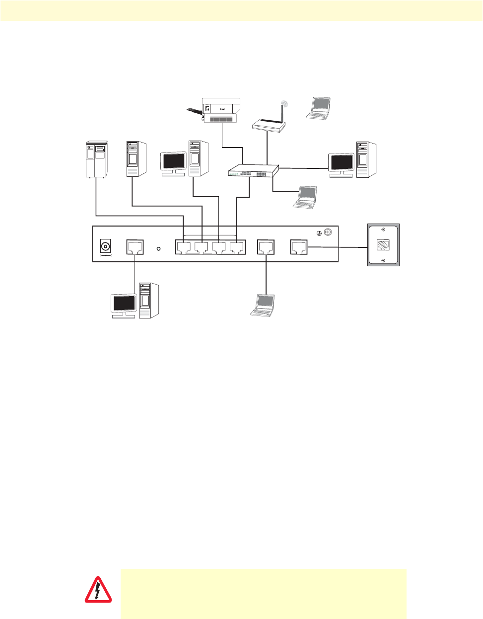
Network diagram
Draw a network overview diagram that displays all neighboring IP nodes, connected elements and
telephony components. Figure 5 shows possible network connections to the Model 3202.
Figure 5. Model 3202 connection diagram
IP related information
Before you can set up the basic IP connectivity for your Model 3202 series you should have the following
information:
•IP addresses used for Ethernet LAN and WAN ports
•Subnet mask used for Ethernet LAN and WAN ports
You will need a PC (or equivalent) with a VT-100 emulation program (e.g. HyperTerminal) to configure the
software on your Model 3202.
AC Power Mains
If you suspect that your AC power is not reliable, for example if room lights flicker often or there is machinery
with large motors nearby, have a qualified professional test the power. Install a power conditioner if necessary.
Refer to “Grounding the Model 3202 and connecting power” on page 30.
The mains outlet that is utilized to power the equipment must be within
1 foot (3 meters) of the device and shall be easily accessible.
+-
DC 9V CONSOLE
RST
MGMT LINE
LAN
Desktop PC Laptop computer
LAN
Printer
Switch
Notebook
Notebook
Desktop PC
Desktop PC
ServerRAID Drive
WAP
WARNING
Installing the Model 3202 29
Model 3202 Getting Started Guide 3 • Hardware installation
Note When setting up your Model 3202 you must consider cable-length
limitations and potential electromagnetic interference (EMI) as
defined by the applicable local and international regulations. Ensure
that your site is properly prepared before beginning installation.
Location and mounting requirements
The Model 3202 is intended to be placed on a desktop or similar sturdy, flat surface that offers easy access to
the cables. Additionally, you should consider the need to access the unit for future upgrades and maintenance.
This completes the planning phase for installation. The next section begins the installation procedures.
Installing the Model 3202
Unpacking the Model 3202
Inspect the shipping carton for external damage. Note any damage before removing the container contents.
Report any equipment damage to the shipping carrier immediately for claim purposes. Save all packing mate-
rial in case you need to return an item to the factory for servicing.
The Model 3202 comes with the following items:
•Model 3202 Quick Start Guide
•Model 3202
•An RJ-45-to-RJ-45 cable for use with the console and Ethernet ports
•A DB-9-to-RJ-45 (EIA-561) adapter for connecting a PC’s serial port to the Model 3202 console port
•CD-ROM containing product literature and the Model 3202 Getting Started Guide
Note Power cables are shipped separately from the Model 3202
Connecting cables
1. Connect the Ethernet cable to the MGMT port. Model 3202 supports audi-MDIX switching so you may
use a crossover or straight-through cable.
2. Connect one end of a phone cable to the LINE port and the other end of the cable to a wall jack.
The Interconnecting cables must be acceptable for external use
and must be rated for the proper application with respect to volt-
age, current, anticipated temperature, flammability, and
mechanical serviceability.
Do not work on the system or connect or disconnect cables during periods of
lightning activity.
CAUTION
WARNING
Installing the Model 3202 30
Model 3202 Getting Started Guide 3 • Hardware installation
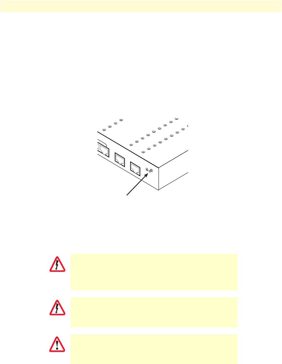
Grounding the Model 3202 and connecting power
In connecting to the power source, it is important to establish a good grounding connection first, then the
power connection. Do the following:
1. Assemble a ground wire using #10 AWG wire with green-colored insulation and two ring terminals. Make
the wire long enough to reach one of the following earth ground sources:
– The building ground rod (generally located at the site’s main service entrance)
– A sprinkler system pipe
– A cold-water pipe
– Building structural steel
Figure 6. Grounding stud
2. Install the grounding wire between the grounding stud (see figure 6) and the grounding source.
3. Connect the power adapter to the DC 9V port on the Model 3202, and then connect to the power source.
Mains Voltage: Do not open the case the when the power cord is attached.
Line voltages are present within the power supply when the power cords are
connected. The mains outlet that is utilized to power the device shall be
within 10 feet (3 meters) of the device, shall be easily accessible, and pro-
tected by a circuit breaker.
The Model 3202 is not shipped with power cables. For AC powered units,
ensure that the power cable used meets all applicable standards for the coun-
try in which it is to be installed, and that it is connected to a wall outlet which
has earth ground.
The power supply automatically adjusts to accept an input volt-
age from 100 to 240 VAC(50/60 Hz).
MGMT LINE
4
Grounding stud
WARNING
WARNING
IMPORTANT

Configuring the Model 3202 31
Model 3202 Getting Started Guide 3 • Hardware installation
Configuring the Model 3202
There are three different ways you can configure the Model 3202: the serial console, Telnet, or a web browser.
Web configuration requirements
Make sure that the PC you use for configuration has an Ethernet adapter and TCP/IP installed.
The Model 3202 provides a browser interface that allows you to configure and manage the modem. After you
set up the IP address for the 3202, you can access the modem's Web interface applications directly in your
browser by entering the IP address. You can then use your Web browser to manage and configure the unit from
a PC.
Note For detailed information on configuring the Model 3202 through the
Web interface, see Chapter 4, “Web configuration” on page 32.
Console configuration requirements
To configure the Model 3202 through the serial console, you can directly connect a terminal or a PC equipped
with a terminal-emulation program (such as Hyper Terminal) to the modem's console port.
Use the supplied serial cable (RJ-45 to DB9F) to connect the Model 3202 to a PC. After marking the connec-
tion, configure the terminal-emulation program to use the following parameters:
•9600 bps
•8 data bits
•no parity
•1 stop bit
Note For detailed information on configuring the Model 3202 through the
serial console, see Chapter 5, “Console and Telnet configuration” on
page 65.
Telnet configuration requirements
Make sure that the PC you use for configuration has an Ethernet adapter and TCP/IP installed. The Model
3202 supports Telnet for remote configuration. The command is “telnet 192.168.1.1” . When prompted for
the username and password for remote login, use admin for username and admin for password. All display
screens are the same as serial console configuration.
The default IP address is 192.168.1.1, but you may change the IP address for your application.
Note For detailed information on configuring the Model 3202 through
Telnet, see Chapter 5, “Console and Telnet configuration” on
page 65.

32
Chapter 4 Web configuration
Chapter contents
Introduction..........................................................................................................................................................34
Setting Up the WMI .............................................................................................................................................34
TCP/IP setup ..................................................................................................................................................34
System Login ..................................................................................................................................................34
Basic Configuration Options .................................................................................................................................35
Operation mode and MGMT port .................................................................................................................35
DHCP server ..................................................................................................................................................36
LAN ...............................................................................................................................................................37
Review and save basic setup changes ...............................................................................................................38
Advanced Configuration Options..........................................................................................................................39
LINE ..............................................................................................................................................................39
Line Type ..................................................................................................................................................39
Annex Type ...............................................................................................................................................39
TCPAM Type ...........................................................................................................................................40
Main Rate .................................................................................................................................................40
SNR Margin .............................................................................................................................................40
Line Probe .................................................................................................................................................40
VLAN .............................................................................................................................................................41
802.1Q Tag-Based VLAN .........................................................................................................................43
Tag-Based VLAN Overview ................................................................................................................ 43
Configuring 802.1Q VLAN Tagging .................................................................................................. 44
Port-Based VLAN .....................................................................................................................................46
Port-Based QinQ ......................................................................................................................................47
Quality of Service (QoS) .................................................................................................................................48
Port Based Priority ....................................................................................................................................49
VLAN Tag Priority ...................................................................................................................................50
WRR Scheduling Configuration Example ........................................................................................... 51
IP DSCP Priority ......................................................................................................................................52
Differentiated Services Overview ......................................................................................................... 52
Configuring DSCP Options................................................................................................................ 54
Rate Control ...................................................................................................................................................55
Status Options.......................................................................................................................................................56
LINE Status ....................................................................................................................................................56
MGMT Status ................................................................................................................................................56
LAN Status .....................................................................................................................................................57
Administration Options.........................................................................................................................................57
Security Administration ..................................................................................................................................57
User Profiles ..............................................................................................................................................58
Remote Management Hosts ......................................................................................................................58

33
Model 3202 Getting Started Guide 4 • Web configuration
SNMP Administration ....................................................................................................................................59
Community Pool ......................................................................................................................................60
Trap Host Pool .........................................................................................................................................61
Utility Options......................................................................................................................................................61
System Information ........................................................................................................................................61
Configuration Tool .........................................................................................................................................62
Upgrade ..........................................................................................................................................................63
Logout ............................................................................................................................................................63
Restart ............................................................................................................................................................64

Introduction 34
Model 3202 Getting Started Guide 4 • Web configuration
Introduction
The Model 3202 provides a browser interface that allows you to configure and manage the modem. Make sure
that the PC you use for configuration has an Ethernet adapter and TCP/IP installed. After you set up the IP
address for the 3202, you can access the modem's Web interface applications directly in your browser by enter-
ing the IP address. You can then use your Web browser to manage and configure the unit from a PC.
Setting Up the WMI
This section introduces the configuration and functions of the Web Management Interface (WMI). The WMI
is an HTML-based management interface that allows you to easily set-up and manage the Model 3202.
The Model 3202 offers all monitoring and management features that allow users to manage this Model 3202
form anywhere on the network through a standard browser such as Internet Explorer.
TCP/IP setup
When DHCP is enabled, the Model 3202 acts as a DHCP server in your network. The Model 3202 will auto-
matically assign IP address for the management port connection.
To set up TCP/IP on a Windows PC:
1. Click the Start button. Select the Control Panel.
2. Double-click on the Network icon.
3. In the Configuration window, select the TCP/IP protocol line that has been associated with your network
card and then click the property icon.
4. Click on the IP address tab and select Obtain IP address automatically. Click OK.
System Login
You may use a web browser such as Internet Explorer on your PC to connect the Model 3202. Type “http://”
and the IP address like as “http://192.168.1.1”.
The default IP address and sub net-mask of the MGMT port of the Model 3202 are 192.168.1.1 and
255.255.255.0. If DHCP is disabled, your PC can set the same net-mask such as 192.168.1.x where x is a
number from 2 to 254.
Type the default User name root and default Password root and then click OK. For system security, you should
change the user name and password after initial onfiguration.
Figure 7. System login screen
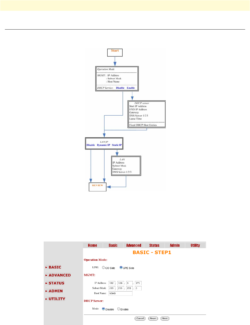
Basic Configuration Options 35
Model 3202 Getting Started Guide 4 • Web configuration
Basic Configuration Options
This section contains information for setting up the operation mode and MGMT port IP, DHCP server, and
LAN via the WMI. Figure 8 shows a flowchart demonstrating basic setup via the WMI for the Model 3202.
Figure 8. Basic setup flowchart
Operation mode and MGMT port
To configure the operation mode and MGMT port in the WMI:
1. From the main menu, click Basic to display the basic installation page.
Figure 9. Operation mode and MGMT port setup page

Basic Configuration Options 36
Model 3202 Getting Started Guide 4 • Web configuration
2. For Operation Mode, select the radio button for CPE (Customer Premises Equipment) or CO (Central
Office). When the unit is connecting with an EFM DSLAM, select CPE as the operation mode. When
using a “LAN to LAN” connection, one side must be set as CO and the other side must be set as CPE.
3. Enter information for the MGMT port. The Model 3202 requires an IP address to be managed over the
network. The factory default IP address is 192.168.1.1. The subnet mask specifies the network number
portion of an IP address. The factory default subnet mask is 255.255.255.0 . You can configure another IP
address and a different subnet mask for management purposes.
–IP: 192.168.1.1
–Subnet Mask: 255.255.255.0
–Host Name: SOHO
Some ISP providers require the Host Name as identification. You may check with your ISP to see if your
Internet service has been configured with a host name. In most cases, you can ignore this field.
4. Select an option for Trigger DHCP Service. If you don't need the DHCP service, select Disable.
5. Click Next to commit your changes and continue to the DHCP Server page (see “DHCP server” on
page 36).
DHCP server
Dynamic Host Configuration Protocol (DHCP) is a communication protocol that allows network adminis-
trators to manage and automate the assignment of Internet Protocol (IP) addresses in an organization's net-
work. Each machine that can connect to the Internet needs a unique IP address. When an organization sets up
the users with a connection to the Internet, an IP address must be assigned to each machine.
Without DHCP, the IP address must be entered manually at each computer. If computers move to another
location in another part of the network, a new IP address must be entered. DHCP lets a network administrator
supervise and distribute IP addresses from a central point and automatically sends a new IP address when a
computer is plugged into a different place in the network. The embedded DHCP server assigns network con-
figuration information to 253 users (max) accessing the Internet in the same time. For example, if the LAN IP
address is 192.168.0.1, the IP range of the LAN is 192.168.0.2 to 192.168.0.254.
To set up the DHCP Server for the Model 3202:
1. Click on Basic from the main menu, set up the Operation Mode and MGMT port, then click Next to
reach the DHCP Server page.
2. The DHCP server assigns the IP from the Start IP Address to the End IP Address. The legal IP address
range is from 0 to 255, but 0 is reserved as the network name and 255 is reserved for broadcast. This
implies that the legal IP address range is from 1 to 254. That means you cannot assign an IP greater than
254 or less than 1.
3. A Lease Time of 72 hours indicates that the DHCP server will reassign IP information every 72 hours.,
which is the default value for the Model 3202. You can set up the Lease Time for a range from 1 to 720
hours according to your application.
4. If you assign a fixed IP address to a device while using DHCP, you must enter the device's MAC address in
the Table of Fixed DHCP Host Entries.
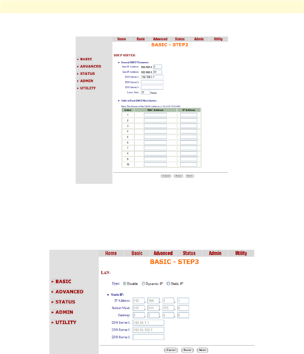
Basic Configuration Options 37
Model 3202 Getting Started Guide 4 • Web configuration
5. Click Next to commit your changes and continue to the LAN page (see “LAN” on page 37).
Figure 10. Basic DHCP setup
LAN
To configure LAN settings through the WMI:
1. Click on Basic from the main menu. Set up the Operation Mode and MGMT port, then click Next. Set
up the DHCP Server, then click Next to reach the LAN page.
Figure 11. LAN setup page
2. Choose an option for the LAN Type. If you select Disable or Dynamic IP, click Next at the bottom of the
screen to save your changes. If you select Static IP, you can enter information for IP, Subnet Mask, Gate-
way and DNS Server's IP.
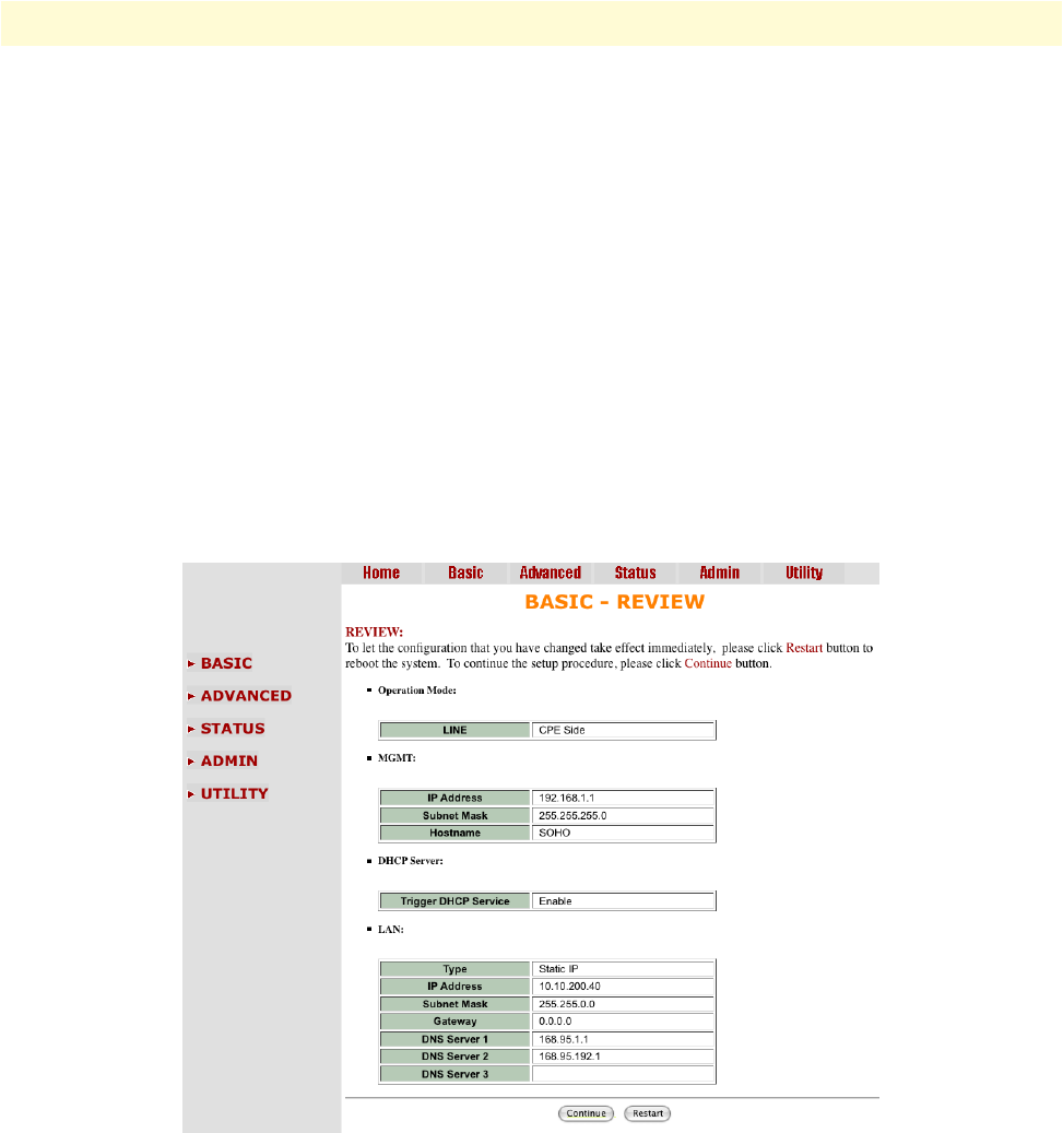
Basic Configuration Options 38
Model 3202 Getting Started Guide 4 • Web configuration
3. If you select Static IP as the LAN Type, enter details in the Static IP section. The default values for Static
IP are:
–IP Address: 192.168.2.1
–Subnet Mask: 255.255.255.0
–Gateway: 0.0.0.0
–DNS Server 1: 168.95.1.1
–DNS Server 2: 168.95.192.1
4. Click Next to commit your changes and continue to the Review page (see “Review and save basic setup
changes” on page 38).
Review and save basic setup changes
1. Once you have entered information on the pages for Operation Mode and MGMT Port, DHCP Server,
and LAN, the Basic Setup Review page will display to confirm your changes.
Figure 12. Review and save basic setup changes
2. Look over the Review page to confirm the desired settings.
3. Click Restart to reboot the Model 3202 with the new settings.
4. Click Continue to configure other options.
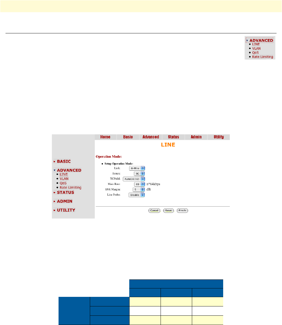
Advanced Configuration Options 39
Model 3202 Getting Started Guide 4 • Web configuration
Advanced Configuration Options
This section contains information for setting up advanced options for the Model 3202 via the
WMI. Advanced setup contains Model 3202 EFM, VLAN, QoS and Rate Control parameters.
Note The advanced functions are only for advanced users to setup
advanced functions. The incorrect advanced settings will affect the
performance of the Model 3202 or cause system errors and isconnec-
tion.
LINE
Click on LINE under Advanced on the main menu to reach the LINE advanced configuration page. You can
setup the Line Type (number of wires), Annex Type, TCPAM Type, Main Rate, SNR Margin, and Line Probe
settings for LINE parameters.
Figure 13. LINE page
Line Type
Select the line type for your model from the Link drop-down list. Line type means how many wires you want
to use on the DSL connection. For example, you can select 2-wire, 4-wire or 8-wire line type for the 8-wire
model.
Annex Type
Select the appropriate Annex type from the drop-down list. Annex AF describes the transmission and perfor-
mance requirements for North America. Annex BG describes performance and transmission requirements for
Europe.
Table 7. Line Type Chart
Line Type
2-wire 4-wire 8-wire
Model
Type
2-wire model •
4-wire model • •
8-wire model •••
Advanced Configuration Options 40
Model 3202 Getting Started Guide 4 • Web configuration
TCPAM Type
TCPAM (Trellis Coded Pulse Amplitude Modulation) is the standard used for line coding. Select the TCPAM
type from the drop-down list. Auto is the default option for TCPAM. You can also manually set the TCPAM
type.
Main Rate
Select the DSL rate for your model from the Main Rate drop-down list. The main rate is the multiple of
64kbps, 128kbps, or 256kpbs- depending on your model type. Use Table 8 to determine the best main rate for
your model.
SNR Margin
Select the desired SNR Margin value from the drop-down list. SNR margin is an index of line connection
quality. You can see the actual SNR margin in STATUS. You will experience better line connection quality for
larger SNR margin values.
For example, if you set the SNR margin is 5, the DSL connection will drop and reconnect when the SNR mar-
gin is lower than 5. On the other hand, the device will reduce the line rate and reconnect for better line con-
nection quality. You may select the SNR margin from the range -10 to 21.
Line Probe
For adaptive mode applications, set the Line Probe to Enable. The Model 3202 will adapt the data rate accord-
ing to the line status. The screen will prompt the parameters that will be written in NVRAM. Check the
parameters before writing in NVRAM.
For all other applications, set the Line Probe to Disable.
Click Restart to reboot the Model 3202 with the new settings. Click Continue to configure other options.
Table 8. Main Rate Chart
Model Type Multiple TCPAM-16
= 3–60
TCPAM-32
= 12–89
TCPAM-64
= 90–177
2-wire model 64 192–3840 768–5696 5760-11328
4-wire model 128 384–7680 1536–11392 11520-22656
8-wire model 256 768–15360 3072–22784 23040-45312
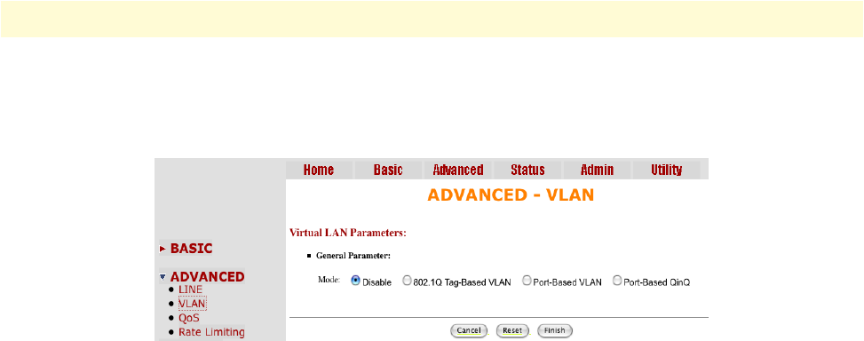
Advanced Configuration Options 41
Model 3202 Getting Started Guide 4 • Web configuration
VLAN
Click on VLAN under Advanced on the main menu to reach the VLAN advanced configuration page.
Figure 14. VLAN page
VLAN (Virtual Local Area Network) allows a physical network to be partitioned into multiple logical net-
works. Devices on a logical network belong to one group. A device can belong to more than one group. With
VLAN, a device cannot directly talk to or hear from devices that are not in the same group.
With MTU (Multi-Tenant Unit) applications, VLAN is vital in providing isolation and security among the
subscribers. When properly configured, VLAN prevents one subscriber from accessing the network resources
of another on the same LAN.
VLAN also increases network performance by limiting broadcasts to a smaller and more manageable logical
broadcast domain. In traditional switched environments, all broadcast packets go to each every individual port.
With VLAN, all broadcasts are confined to a specific broadcast domain.
You can select from two types of VLAN: 802.1Q Tag-Based VLAN and Port-Based VLAN. The VLAN Setup
screen changes depending on whether you choose 802.1Q Tag-Based VLAN type or Port Based VLAN type.
The IEEE 802.1Q defines the operation of VLAN bridges that permit the definition, operation, and adminis-
tration of VLAN topologies within a bridged LAN infrastructure.
Figure 15 on page 42 shows a diagram of possible VLAN connections.
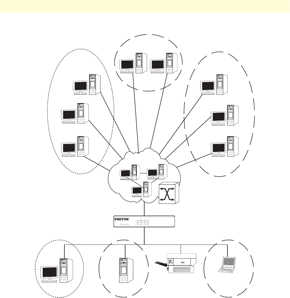
Advanced Configuration Options 42
Model 3202 Getting Started Guide 4 • Web configuration
Figure 15. VLAN Diagram
VID 20
VID 30VID 10
PWRALMDIAG
WAN
LAN100M
LINK/ACT
LINK
1 2 3 4
RocketLink™ 3200
G.SHDSL EFM Modem
VID 10 VID 20 VID 30
LAN3
LAN1
LAN2
LAN4
RocketLink Model 3202
EFM G.SHDSL Modem
Backbone
WAN5
WAN4
WAN6
WAN7
WAN8
WAN3
WAN2
WAN1
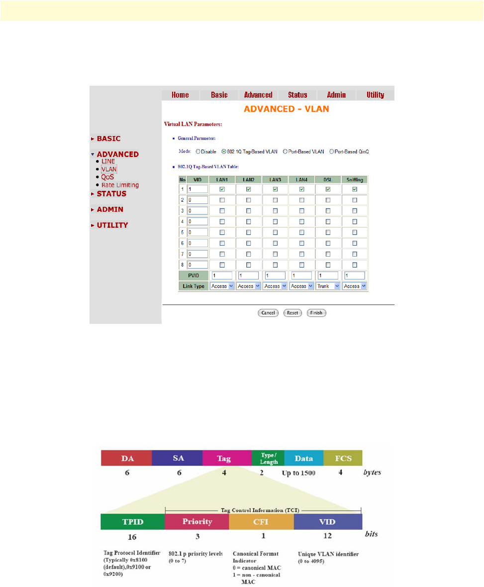
Advanced Configuration Options 43
Model 3202 Getting Started Guide 4 • Web configuration
802.1Q Tag-Based VLAN
Click on VLAN under Advanced on the main menu to reach the VLAN advanced configuration page. Then,
select the radio button for 802.1Q Tag-Based VLAN to display the configuration options.
Figure 16. 802.1Q Tag-Based VLAN page
•VID (Virtual LAN ID): A number to identify the VLAN segment. Select from 1 to 4094.
•PVID (Port VID): An untagged member of the default VLAN. Select from 1 to 4094.
•Link Type: Select from Access or Trunk. Access means the port can receive or send untagged packets. Trunk
means that the port can receive or send tagged packets.
Tag-Based VLAN Overview. Figure 17 shows the breakdown of the VLAN tag field.
Figure 17. VLAN tag field
The Tag Control Information (TCI) section of a VLAN tag includes information on the user Priority level,
the Canonical Format Indicator (CFI) and VLAN ID (VID).
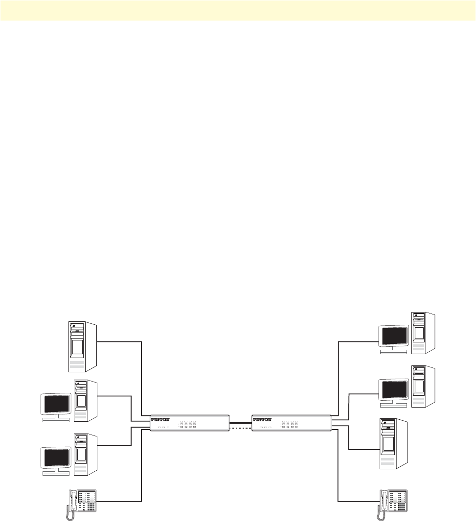
Advanced Configuration Options 44
Model 3202 Getting Started Guide 4 • Web configuration
•Tag Protocol Identifier (TPID) is a defined value of 8100 in hex. When a frame has the EtherType equal to
8100, this frame carries the tag IEEE 802.1Q / 802.1P.
•User Priority defines the priority level for different classes of traffic. There are 8 possible priority levels, with
0 being the lowest priority level and 7 being the highest level. IEEE 802.1P defines the operation for these
3 user priority bits.
•Canonical Format Indicator (CFI) is always set to zero for Ethernet switches. CFI is used for compatibility
reasons between an Ethernet-type network and Token Ring-type network. If a frame received at an Ethernet
port has a CFI set to 1, then that frame should not be forwarded as it is to an untagged port.
•VLAN ID (VID) is the unique identification number of the VLAN, which is used by the standard 802.1Q.
It has 12 bits and allows the identification of 4096 (212) VLANs. Of the 4096 possible VIDs, a VID of 0 is
used to identify priority frames and the value 4095 (FFF) is reserved, so the maximum possible VLAN con-
figurations are 4,094.
The Model 3202 initially configures one VLAN by default, VID=1. A port such as LAN1–4, DSL or sniffing
can have only one Port VID (PVID), but can have as many VID groups as the Model 3202 has memory in its
VLAN table to store them.
Ports in the same VLAN group share the same frame broadcast domin thus increase network performance
through reduced boardcast traffic. You can modify VLAN groups at any time by adding, moving or changing
ports without any re-cabling.
Figure 18. 802.1Q VLAN diagram
Configuring 802.1Q VLAN Tagging. Before enabling VLANs for the Model 3202, you must first assign each
port to the VLAN group(s) in which it will participate. By default all ports are assigned to VLAN1 as untagged
ports. Add a port as a tagged port if you want it to carry traffic for one or more VLANs, and any intermediate
network devices or the host at the other end of the connection supports VLANs. Then, assign ports on the
other VLAN-aware network devices along the path that will carry this traffic to the same VLAN(s), either man-
SERVER
RocketLink Model 3202
Modem connection
LAN1
LAN2
LAN3
LAN4
LAN1
LAN2
LAN3
LAN4
SERVER
VOIP VOIP
802.1Q VLAN
STU-C STU-R
PWR ALM DIAG
WAN
LAN 100M
LINK/ACT
LINK
1 2 3 4
RocketLink™ 3200
G.SHDSL EFM Modem
PWR ALM DIAG
WAN
LAN 100M
LINK/ACT
LINK
1 2 3 4
RocketLink™ 3200
G.SHDSL EFM Modem
123
45 6
7 8 9
*0#
123
45 6
7 8 9
*0#

Advanced Configuration Options 45
Model 3202 Getting Started Guide 4 • Web configuration
ually or dynamically using Generic VLAN Routing Protocol (GVRP). However, if you want a port on this
Model 3202 to participate in one or more VLANs, but none of the intermediate network devices nor the host
at the other end of the connection supports VLANs, then you should add this port to the VLAN as an
untagged port.
Note VLAN-tagged frames can pass through VLAN-aware or VLAN-
unaware network inter-connection devices, but the VLAN tags
should be stripped off before passing it on to any end-node host that
does not support VLAN tagging.
•VLAN Classification - When the Model 3202 receives a frame, it classifies the frame in one of two ways. If
the frame is untagged, the Model 3202 assigns the frame to an associated VLAN (based on the default
VLAN ID of the receiving port). But if the frame is tagged, the Model 3202 uses the tagged VLAN ID to
identify the port broadcast domain of the frame.
•Port Overlapping - You can use port overlapping to allow access to commonly shared network resources
among different VLAN groups, such as file servers or printers.
•Untagged VLANs - Untagged (or static) VLANs are typically used to reduce broadcast traffic and to
increase security. A group of network users assigned to a VLAN form a broadcast domain that is separate
from other VLANs configured on the Model 3202. Packets are forwarded only between ports that are desig-
nated for the same VLAN. Untagged VLANs can be used to manually isolate user groups or subnets.
•Port VID (PVID) - A PVID is a VLAN ID assigned to untagged frames received on the interface. (Default:
1). If an interface is not a member of VLAN 1 and you assign its PVID to this VLAN, the interface will
automatically be added to VLAN 1 as an untagged member. For all other VLANs, an interface must first be
configured as an untagged member before you can assign its PVID to that group.
•Link Type - The Link Type determines the types of frames the port can accept. Access means the port can
only receive or send untagged frame types. Trunk means that the port can only receive or send tagged frame
types.
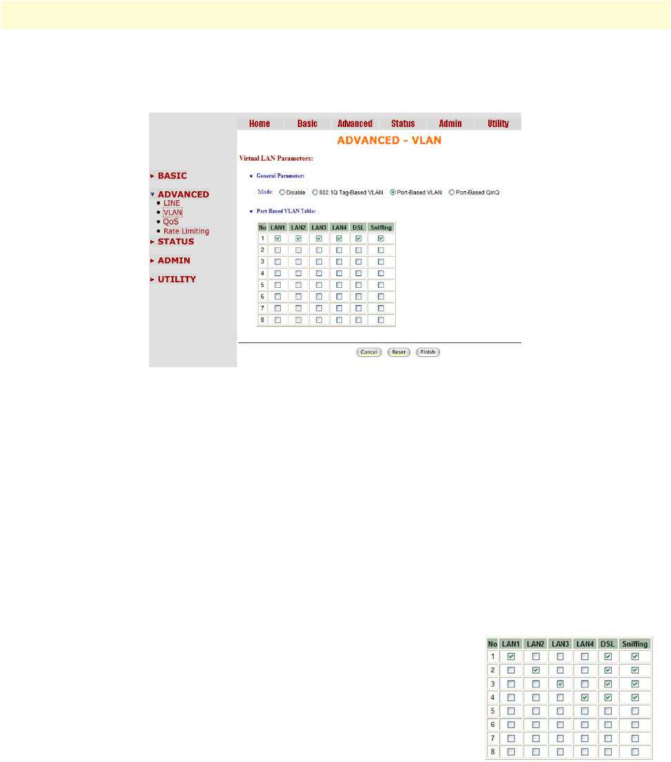
Advanced Configuration Options 46
Model 3202 Getting Started Guide 4 • Web configuration
Port-Based VLAN
Click on VLAN under Advanced on the main menu to reach the VLAN advanced configuration page. Then,
select the radio button for Port-Based VLAN to display the configuration options.
Figure 19. Port-Based VLAN page
Port-Based VLANs are VLANs where the packet forwarding decision is based on the destination MAC address
and its associated port. When using the port-based VLAN, the port is assigned to a specific VLAN indepen-
dent of the user or system attached to the port. This means all users attached to the port should be members in
the same VLAN. The network administrator typically performs the VLAN assignment. The port configuration
is static and cannot be automatically changed to another VLAN without manual reconfiguration.
As with other VLAN approaches, the packets forwarded using this method do not leak into other VLAN
domains on the network. After a port has been assigned to a VLAN, the port cannot send to or receive from
devices in another VLAN.
The default setting for port-based VLANs (shown in Figure 19) is that all of ports are connected so that all
ports can communicate with each other. Essentially, there are no virtual LANs. This option is the most flexible
but the least secure.
If you click the LAN1 to LAN4 only with DSL and Sniffing (as shown here),
there are port isolation means that each LAN’s port can only communicate
with management port and cannot communicate with each other. This option
is the most limiting but also the most secure.
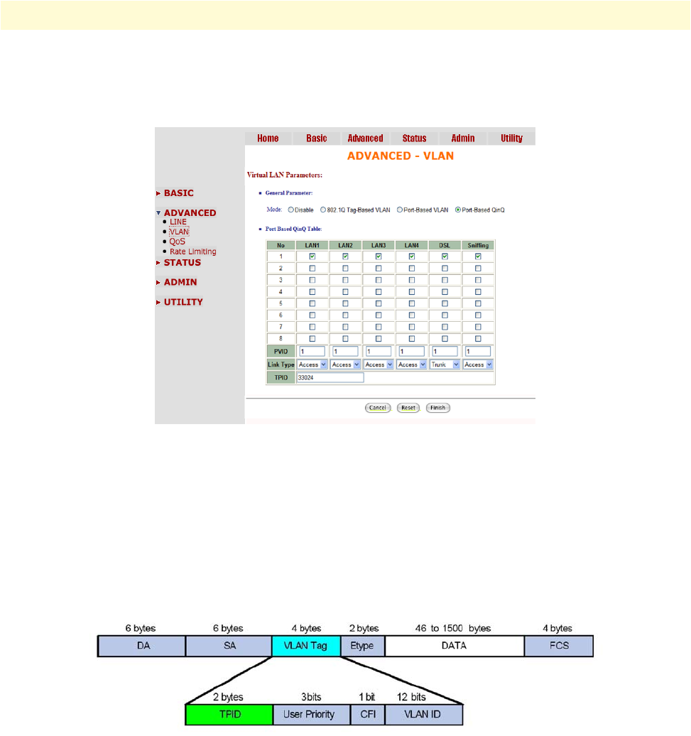
Advanced Configuration Options 47
Model 3202 Getting Started Guide 4 • Web configuration
Port-Based QinQ
Click on VLAN under Advanced on the main menu to reach the VLAN advanced configuration page. Then,
select the radio button for Port-Based QinQ to display the configuration options.
Figure 20. Port-Based QinQ VLAN page
•PVID (Port VID): An untagged member of the default VLAN. Select from 1 to 4094.
•TPID (Tag Protocol Identifier): Enter 33024 for IEEE802.1Q .
•Link Type: Select from Access or Trunk. Access means the port can receive or send untagged packets. Trunk
means that the port can receive or send tagged packets.
A VLAN tag uses the tag protocol identifier (TPID) field to identify the protocol type of the tag. The value of
this field, as defined in IEEE 802.1Q, is 0x8100 (33024).
Figure 21. VLAN Tag structure of an Ethernet frame
On devices of different vendors, the TPID of the outer VLAN tag of QinQ frames may have different default
values. You can set or modify this TPID value, so that the QinQ frames, when arriving at the public network,
carries the TPID value of a specific vendor to allow interoperation with devices of that vendor.
The TPID in an Ethernet frame has the same position with the protocol type field in a frame without a VLAN
tag. To avoid chaotic packet forwarding and receiving, you cannot set the TPID value to any of the values in
table 9 on page 48.
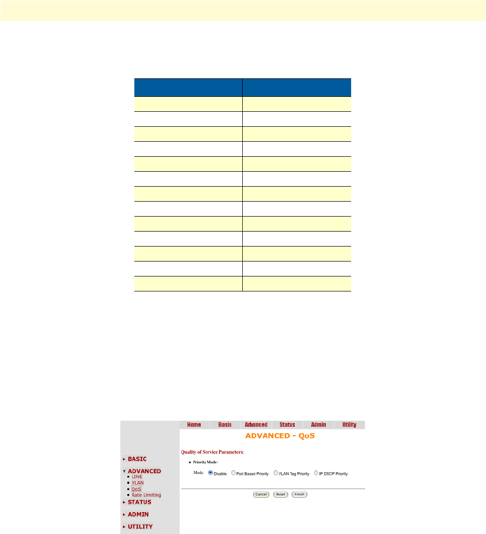
Advanced Configuration Options 48
Model 3202 Getting Started Guide 4 • Web configuration
Quality of Service (QoS)
Quality of Service (QoS) refers to both a network's ability to deliver data with minimum delay, and the net-
working methods used to control the use of bandwidth. Without QoS, all traffic date is equally likely to be
dropped when the network is congested. This can cause a reduction in network performance and mark the net-
work inadequate for time-critical application such as video-on-demand.
Click on QoS under Advanced on the main menu to reach the QoS advanced configuration page.
Figure 22. QoS page
QoS (Quality of Service) is used to decide which devices can get priorities to pass though the Model 3202 once
the bandwidth is exhausted or fully saturated.
There are three types of QoS priority modes: Port Based Priority, VLAN Tag Priority and IP DSCP Priority.
You can also disable the QoS function.
Table 9. Reserved Protocol Values
Protocol Type Value
ARP 0x0806
PUP 0x0200
RARP 0x8035
IP 0x0800
IPv6 0x86DD
PPPoE 0x8863/0x8864
MPLS 0x8847/0x8848
IPX/SPX 0x8137
IS-IS 0x8000
LACP 0x8809
802.1x 0x888E
Cluster 0x88A7
Reserved 0xFFFD/0xFFFE/0xFFFF
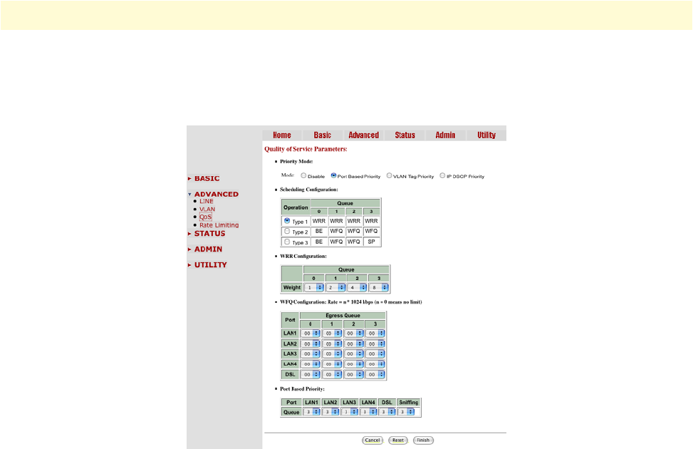
Advanced Configuration Options 49
Model 3202 Getting Started Guide 4 • Web configuration
Port Based Priority
Click on QoS under Advanced on the main menu to reach the QoS advanced configuration page. Then, select
the radio button for Port Based Priority to display the configuration options.
Figure 23. QoS - Port Based Priority page
In the Port Based Priority table, select the ports that the port-based priority rule should be applied. There six
ports to choose from: LAN1, LAN2, LAN3, LAN4, DSL and Sniffing.
In the Scheduling Configuration section, you can set up the Queue type from type 0 to type 3. Each Queue
type can setu p the queue Weight from 1 to 15.
The Queuing method is used to configure queuing algorithms for outgoing traffic. Queuing algorithms allows
the Model 3202 to maintain separate queues for packets from each individual source or flow and prevent a
source from monopolizing the bandwidth.
The Queue types are Weight Round Robin (WRR), Best Effort (BE), and Strictly Priority (SP).
•WRR services on a rotating basis and is activated only when a port has more traffic than it can handle. A
queue is a given an amount of bandwidth irrespective of the incoming traffic on that port. The queue then
moves to the back of the list. The next queue is given an equal amount of bandwidth, and then moves to the
end of the list, and so on, depending on the number of queues being used, This works in a looping fashion
until a queue is empty.
•BE is used for data applications or any non-classified traffic. This would include e-mail, Internet browsing,
data back-up etc. The BE class is for traffic that can afford to wait and not affect the overall outcome of the
data application.
•SP services queues based on priority only. As traffic comes into the Model 3202, traffic on the highest prior-
ity queue, Q3 is transmitted first. When that queue empties, traffic on the next highest-priority queue, Q2
transmitted until Q2 empties, and then traffic is transmitted on Q1 and so on. If higher priority queues
never empty, then traffic on lower priority never gets sent. The SP class is typically for video applications
that require a fixed amount of bandwidth to be considered good quality.
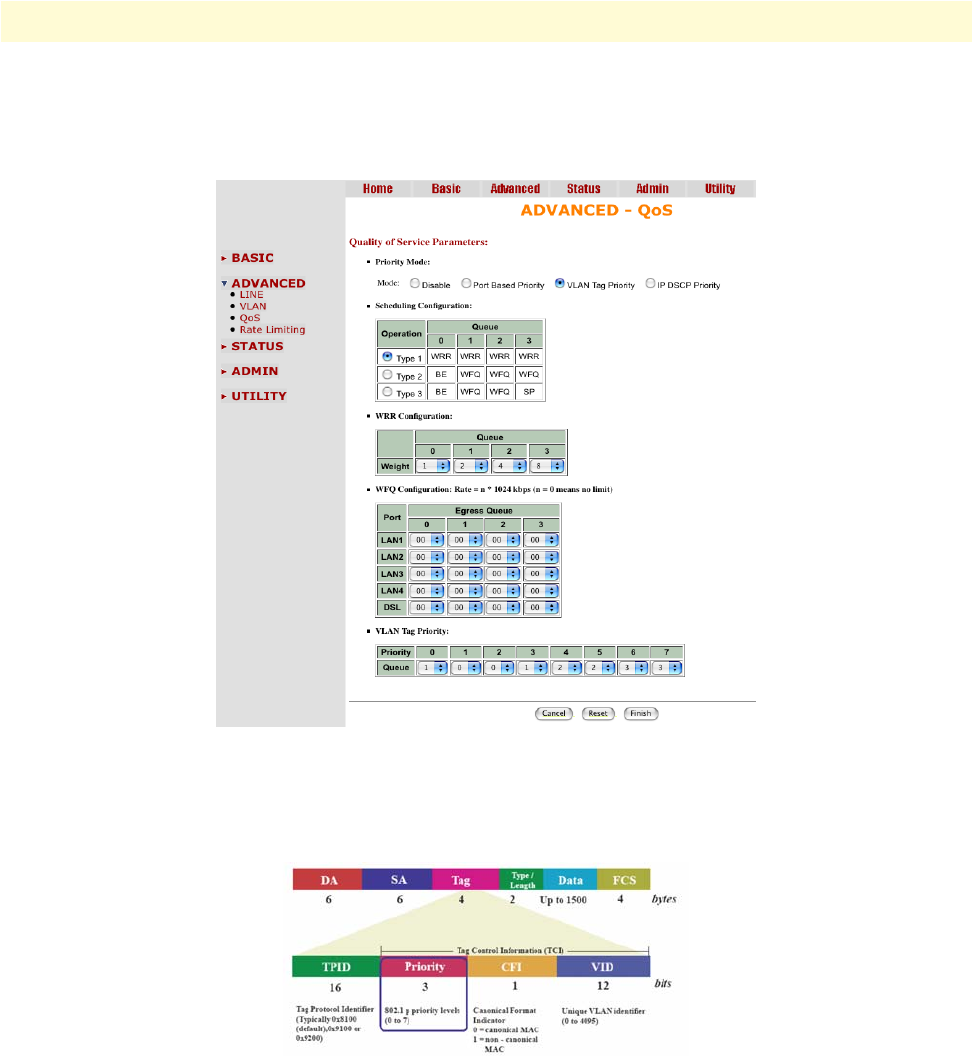
Advanced Configuration Options 50
Model 3202 Getting Started Guide 4 • Web configuration
VLAN Tag Priority
Click on QoS under Advanced on the main menu to reach the QoS advanced configuration page. Then, select
the radio button for VLAN Tag Priority to display the configuration options.
Figure 24. QoS - VLAN Tag Priority page
VLAN Tag Priority uses the tag field information which has been inserted into an Ethernet frame. If a port has
an 802.1Q-compliant device attached (such as this modem), these tagged frames can carry VLAN membership
information.
Figure 25. IEEE 802.1Q Tagged Frame for Ethernet
Priority defines the user priority level for different classes of traffic. There are 8 possible priority levels, with 0
being the lowest priority level and 7 being the highest level. Each Priority level can be set queue from 0 to 3.
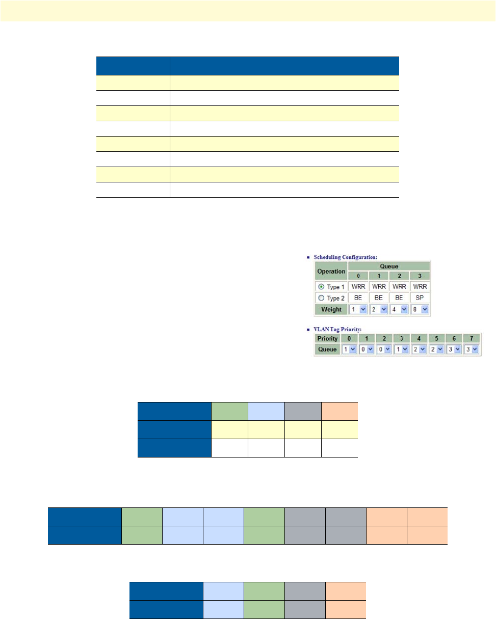
Advanced Configuration Options 51
Model 3202 Getting Started Guide 4 • Web configuration
In the Scheduling Configuration table, you can set up the type of QoS operation from 1 to 3. You can also set
up the Queue Weight from 1 to 15.
WRR Scheduling Configuration Example. For example, you
can set the Model 3202 use Weighted Round-Robin (WRR) queu-
ing that specifies a relative weight of each queue. WRR uses a pre-
defined relative weight for each queue that determines the
percentage of service time to services each queue before moving on
to the next queue. This prevents the head-of-line blocking that can
occur with strict priority queuing.
For this example, set up the WRR (Type 1) to share bandwidth by using scheduling weights 1, 2, 4 and 8 for
queues 0 through 3 respectively.
According to above two tables, we can get the mapping QoS values to Egress Queues as the following:ely.
Table 10. VLAN Tag Priority Levels
Priority Level Traffic Type
0 (default) Best Effort
1Background
2Spare
3Excellent Effort
4Controlled Load
5Video, less than 100 milliseconds latency and jitter
6Voice, less than 10 milliseconds latency and jitter
7Network Control
Table 11. WRR Scheduling Configuration Example Values
Queue 0123
Type 1 WRR WRR WRR WRR
Weight 1248
Priority 01234567
Queue 10012233
Priority 0123
Queue 1,2 0,3 4,5 6,7
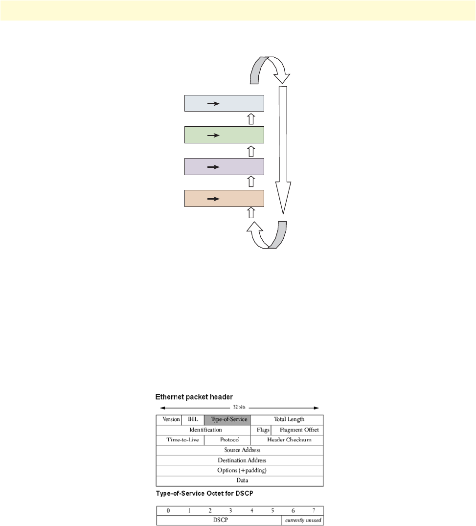
Advanced Configuration Options 52
Model 3202 Getting Started Guide 4 • Web configuration
Figure 26. Service by WRR
IP DSCP Priority
Differentiated Services Overview. Differentiated Services (DiffServ) is a class of service (CoS) model that
enhances best-effort Internet services by differentiating traffic by users, service requirements and other criteria.
Packets are specifically marked, allowing network nodes to provide different levels of service, as appropriate for
video playback, voice calls or other delay-sensitive applications, via priority queuing or bandwidth allocation.
DiffServ defines a new DS (Differentiated Services) field to replace the Type of Service (ToS) field in the IP
header. The DS field contains a 2-bits unused field and 6-bits DSCP field which can define up to 64 service
levels. Figure 27 shows the DS field:
Figure 27. Differentiated Services field
The DSCP value used to identify 64 levels (26=64) of service determines the forwarding behavior that each
packet gets across the DiffServ network. Based on the marking rule different kinds of traffic can be marked for
different priorities of forwarding. Resources can then be allocated according to the DSCP values and the con-
figured policies. Table 12 shows how the bits are used in the DSCP field.
6,7 Queue 3
4,5 Queue 24,5 Queue 2
4,5 Queue 20,3 Queue 1
4,5 Queue 21,2 Queue 0
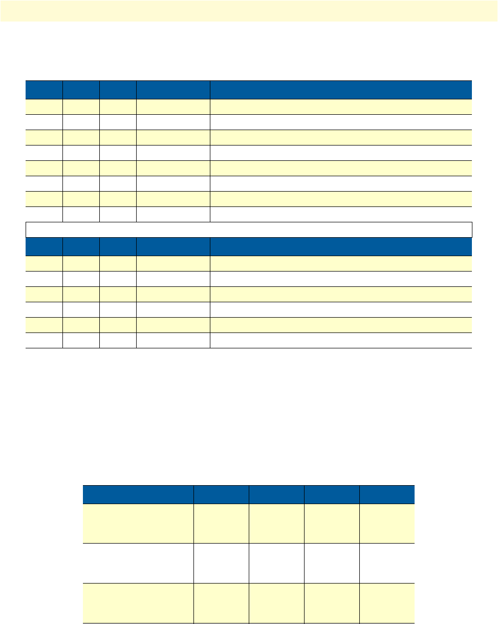
Advanced Configuration Options 53
Model 3202 Getting Started Guide 4 • Web configuration
The standardized DiffServ field of the packet is marked with a value so that the packet receives a particular for-
warding treatment at each network node. RFC 2597 defines the assured forwarding (AF) classes. There are
four AF classes, AF1x through AF4x. Within each class, there are three drop probabilities. Depending on a
given network's policy, packets can be selected for a PHB based on required throughput, delay, jitter, loss, or
according to priority of access to network services. Classes 1 through 4 are referred to as AF classes.
Table 13 illustrates the DSCP coding for specifying the AF class with the probability. Bits 0, 1, and 2 define the
class; bits 3 and 4 specify the drop probability; bit 5 is always 0.
Table 12. Bits in the DSCP field
Bit 0 Bit 1 Bit 2 Precedence Usage
1 1 1 7 Stays the same (link layer and routing protocol keep alive)
1 1 0 6 Stays the same(used for IP routing Protocols)
1 0 1 5 Express Forwarding (EF)
1 0 0 4 Class 4
0 1 1 3 Class 3
0 1 0 2 Class 2
0 0 1 1 Class 1
0 0 0 0 Best effort
Bit 3 Bit 4 Bit 5 Usage Meaning
0 – – Delay Normal
1 – – Delay Low
– 0 – Throughput Normal
– 1 – Throughput High
– – 0 Reliability Normal
– – 1 Reliability High
Table 13. DSCP Coding
Class 1 Class 2 Class 3 Class 4
Low Drop 001010
AF11
DSCP 10
010010
AF21
DSCP 18
011010
AF31
DSCP 26
100010
AF41
DSCP 34
Medium Drop 001100
AF12
DSCP 12
010100
AF22
DSCP 20
011100
AF32
DSCP 28
100100
AF42
DSCP 36
High Drop 001110
AF13
DSCP 14
010110
AF23
DSCP 22
011110
AF33
DSCP 30
100110
AF43
DSCP 38
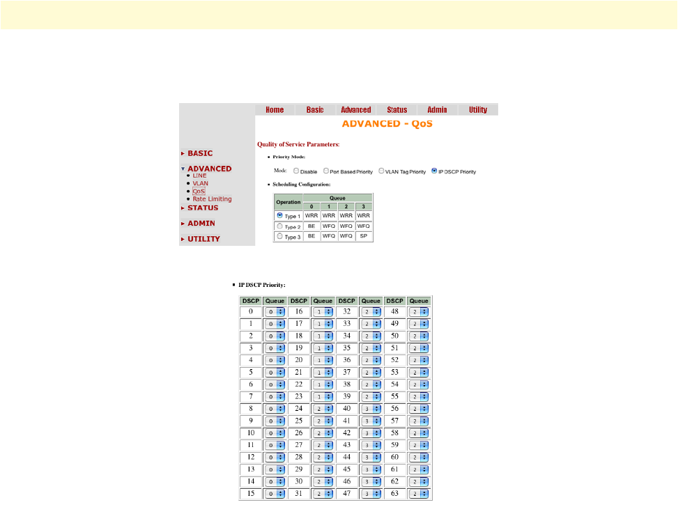
Advanced Configuration Options 54
Model 3202 Getting Started Guide 4 • Web configuration
Configuring DSCP Options. Click on QoS under Advanced on the main menu to reach the QoS advanced
configuration page. Then, select the radio button for IP DSCP Priority to display the configuration options.
Figure 28. QoS - IP DSCP Priority page
Each DSCP value (from 0 to 63) is mapped to a Queue value (from 0 to 3) from the drop-down list The num-
ber 0 represents the lowest priority and number 3 represents the highest priority and according various queuing
strategies to tailor performance to requirements.
If you want to save the changes, click Finish. After you click Finish, review page will display for you to confirm
your changes. To let the configuration that you have changed take effect, click Restart to reboot system. If you
want to continue the setup procedure, click Continue.
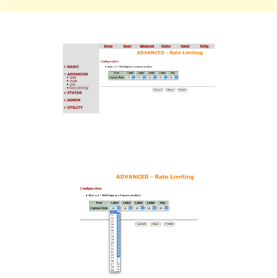
Advanced Configuration Options 55
Model 3202 Getting Started Guide 4 • Web configuration
Rate Control
Click on Rate Control under Advanced on the main menu to reach the Rate Control configuration page.
Figure 29. Rate Control page
Limiting bandwidth to specific users and ports helps control network congestion, ensure high performance,
create efficient networks, and prevent a small number of users from monopolizing network bandwidth.
Rate control can be used to intelligently manage bandwidth allocation in the networking. It can prevent one
user or device from dominating the available network bandwidth, and it allows IT managers to allocate greater
bandwidth to the departments and applications that need it.
Figure 30. Rate Control options
You can set up the date rates limit on each port. The date rates are: No limit, 128K, 256K, 512K, 1M and
2M. The default setting is No limit on each ports.
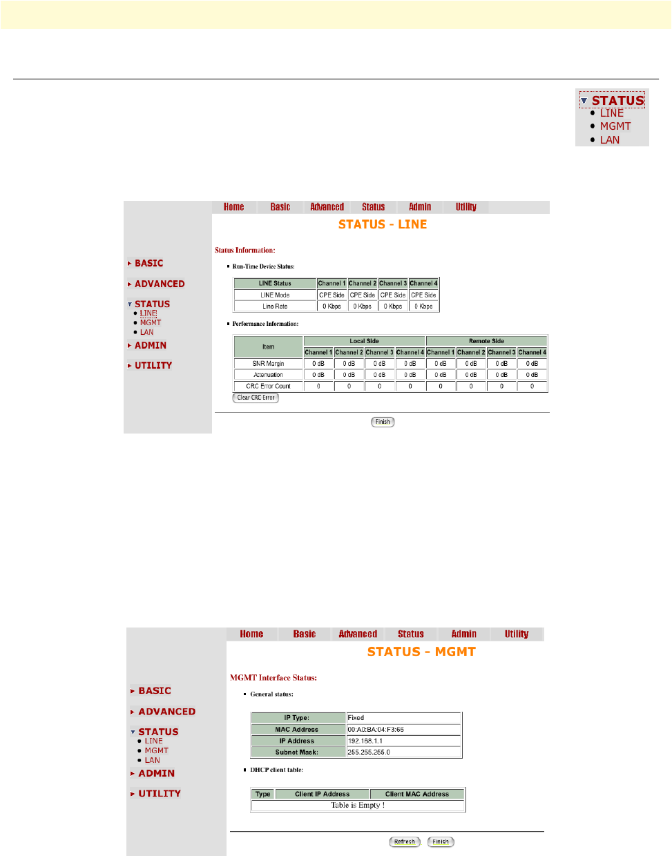
Status Options 56
Model 3202 Getting Started Guide 4 • Web configuration
Status Options
This section contains information for monitoring status options for the Model 3202 via the
WMI. The Status menu contains LINE, MGMT, and LAN parameters.
LINE Status
The LINE Status includes information for the run-time device status, mode, Bitrate and Performance infor-
mation such as SNR margin, atteunation and CRC error count.
Figure 31. LINE Status page (8-wire model shown)
If two Model 3202s have been linked together, you can view their run-time line rate status and performance
information from this screen. If you want to clear the performance data, click Clear CRC Error.
Note CPE side's line rate according to the setting of CO side.
MGMT Status
The MGMT Status page displays information about the MGMT port interface. You can view the general sta-
tus of the MGMT interface and DHCP client table.
Figure 32. MGMT Status page
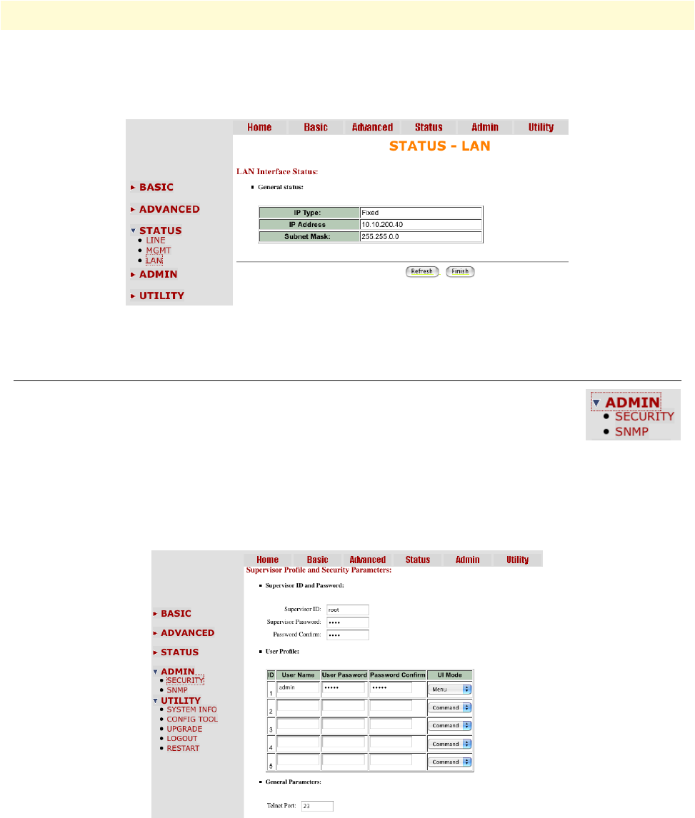
Administration Options 57
Model 3202 Getting Started Guide 4 • Web configuration
LAN Status
The LAN Status page displays information about a LAN port. The system will allow you to select which LAN
port to view.
Figure 33. LAN Status page
Administration Options
This section allows you to conifugre administration options for Security and Simple Network
Management Protocol (SNMP).
Security Administration
For system security, you should change the default user name and password during initial setup. Otherwise,
unauthorized persons can access the Model 3202 and change the parameters. Click Security in the Adminis-
tration menu to set up the parameters.
Figure 34. Security Administration page
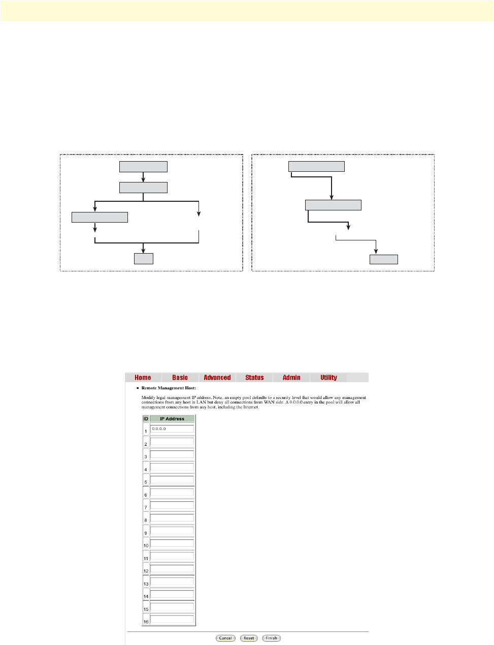
Administration Options 58
Model 3202 Getting Started Guide 4 • Web configuration
User Profiles
For better security, change the Supervisor ID and Supervisor Password for the Model 3202. If you don't set
them, all users will be able to access the Model 3202 using the default Supervisor ID and Supervisor Password
,which is root.
You can authorize five legal users to access the Model 3202 via telnet or console only. There are two UI modes,
menu driven mode and command mode to configure the Model 3202. The default user name and Password
are admin. There are two UI modes, the WMI and the Telnet/Console mode to set up the Model 3202.
Figure 35. Model 3202 configuration modes
Remote Management Hosts
The Remote Management Host section of the Security Administration page enables you to set up the legal IP
addresses from which authorized persons can configure the Model 3202. This is the most secure way for the
network administrator to set up the legal address of configuration.
Figure 36. Remote Management Host section
Telnet Console Mode Web Browser Mode
User Name
Password
Exit
Supervisor Password
All functions are available
Only available functions:
Ping, View Status, Configuration
Supervisor ID
Supervisor Password
Logout
All functions are available
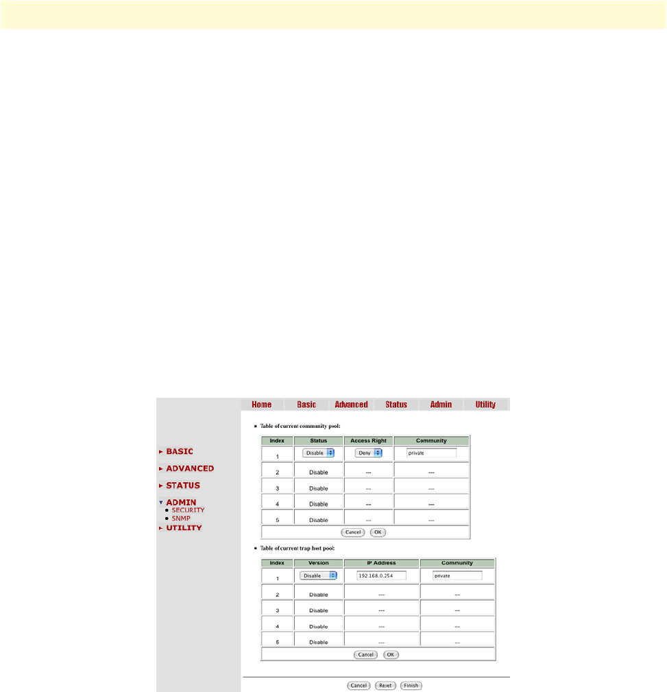
Administration Options 59
Model 3202 Getting Started Guide 4 • Web configuration
A configuration of 0.0.0.0 will allow all hosts on Internet or LAN to access the Model 3202. If you leave the
trusted host list completely blank, you will block all PCs on the WAN from accessing the Model 3202. On the
other hand, only PCs in the LAN can access the Model 3202. If you type the exact IP address in the filed, only
that host can access the Model 3202.
Click Finish to commit your changes. The browser will prompt the configured parameters and check it before
writing into NVRAM. Press Restart to reboot the Model 3202 with the new settings. Click Continue to con-
figure other options.
SNMP Administration
Simple Network Management Protocol (SNMP) provides for the exchange of messages between a network
management client and a network management agent for remote management of network nodes. These mes-
sages contain requests to get and set variables that exist in network nodes in order to obtain statistics, set con-
figuration parameters, and monitor network events. SNMP communications can occur over the LAN or WAN
connection.
The Model 3202 can generate SNMP traps to indicate alarm conditions, and it relies on SNMP community
strings to implement SNMP security. This Model 3202 support both MIB I and MIB II.
Click SNMP in the Administration menu to set up the parameters.
Figure 37. SNMP Administration page
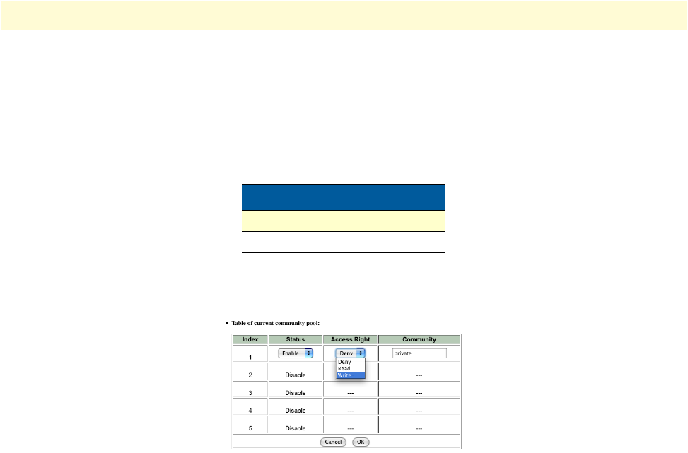
Administration Options 60
Model 3202 Getting Started Guide 4 • Web configuration
Community Pool
An SNMP community is a group of devices and management stations running SNMP. It helps define where
information is sent. The community name is used to identify the group. A SNMP device or agent may belong
to more than one community. It will not request information from management stations that do not belong to
one of its communities.
Click Modify to set up community pools.
Figure 38. SNMP community pool configuration
In the table of the current community pool, you can set up access:
•Status: Enable–Turn on the SNMP function; Disable–Turn off the SNMP function
•Access Right: Deny–Restrict all access; Read–Read-only access; Write–Read/write access
•Community: The password for write access.
After configuring the community pool, click Finish. The browser will prompt the configured parameters and
check it before writing into NVRAM. Press Restart to reboot the Model 3202 with the new settings. Click
Continue to configure other options.
Table 14. Default SNMP Communities
Access Right Community
Read public
Write private
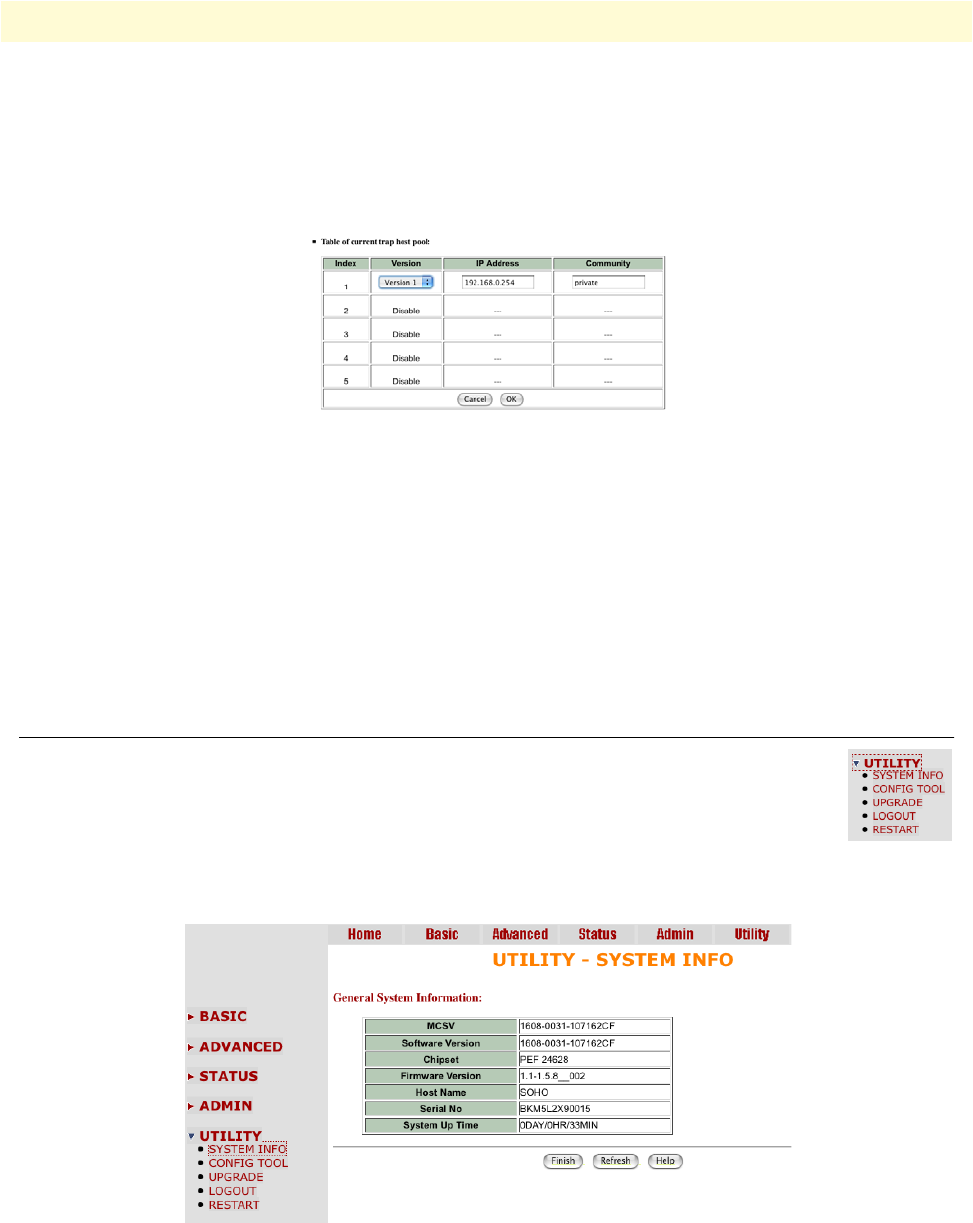
Utility Options 61
Model 3202 Getting Started Guide 4 • Web configuration
Trap Host Pool
In the table of current trap host pool, you can set up the trap host. SNMP trap is an informational message
sent from an SNMP agent to a manager. It is a management station (SNMP application) that receives traps. If
you don’t define a trap host pool, then no traps are issued.
Click Modify to set up the trap host pool.
Figure 39. Trap host pool configuration
•Version: Select version for trap host. (Version 1 is for SNMPv1; Version 2 for SNMPv2; Disable–Turn off )
•IP Address: Enter the trap host IP address
•Community: Enter the community password.
Click OK to finish the setup. The browser will prompt the configured parameters and check it before writing
into NVRAM. Press Restart to reboot the Model 3202 with the new settings. Click Continue to configure
other options.
Utility Options
This section allows you to manage utility options for the Model 3202, including system infor-
mation, the configuration tool, upgrade information, log out of the system, and restart the sys-
tem.
System Information
To review system information, click System Info in the Utility menu.
Figure 40. System Information page
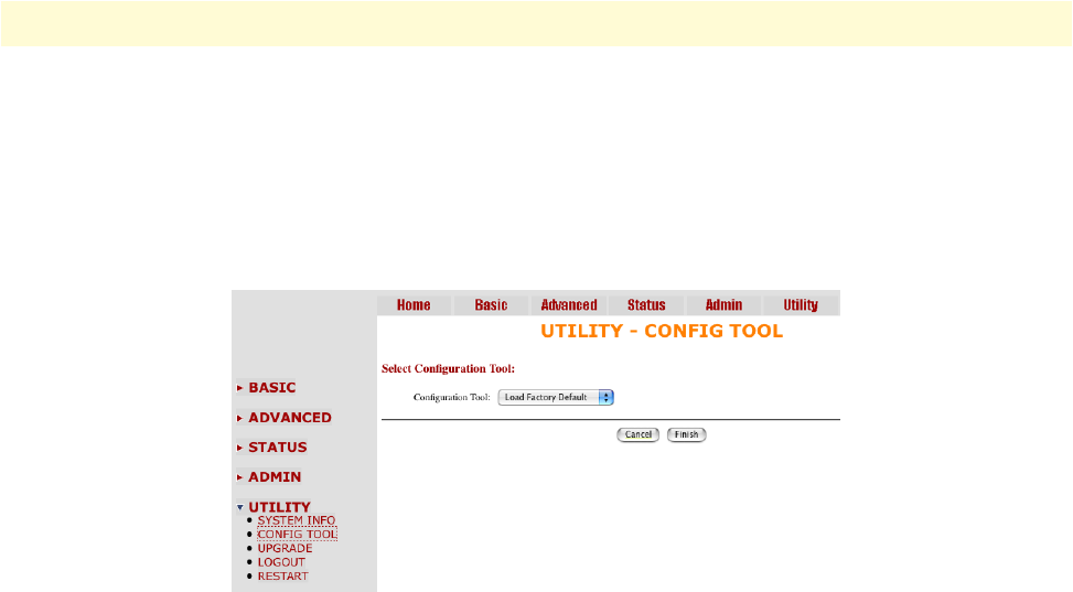
Utility Options 62
Model 3202 Getting Started Guide 4 • Web configuration
You can check the MCSV, Software Version, Chipset, Firmware Version, Host Name and System Up Time.
The System Up Time item let you know how long the Model 3202 has been running since powering up.
Configuration Tool
The configuration tool has three options: Load Factory Default, Restore Configuration, and Backup Config-
uration. Click Config Tool in the Utility menu.
Figure 41. Configuration Tool page
Select the desired configuration function, then click Finish.
•Load Factory Default: The system will load the factory default parameters for the Model 3202.
Note This option will change all of the settings back to factory default. You
will lose all of your current settings.
•Restore Configuration: Use this option to recover the backup configuration easily. Click Finish after select-
ing Restore Configuration. Browse to the backup file then click Finish again. The Model 3202 will auto-
matically restore the saved configuration.
•Backup Configuration: After you configure the Model 3202 with your desired settings, you can use the
Backup Configuration option to save your Model 3202 parameters in the PC. Select the Backup Configu-
ration and then click Finish. Browse to the backup directory, and click Finish again. The Model 3202 will
automatically save the configuration.
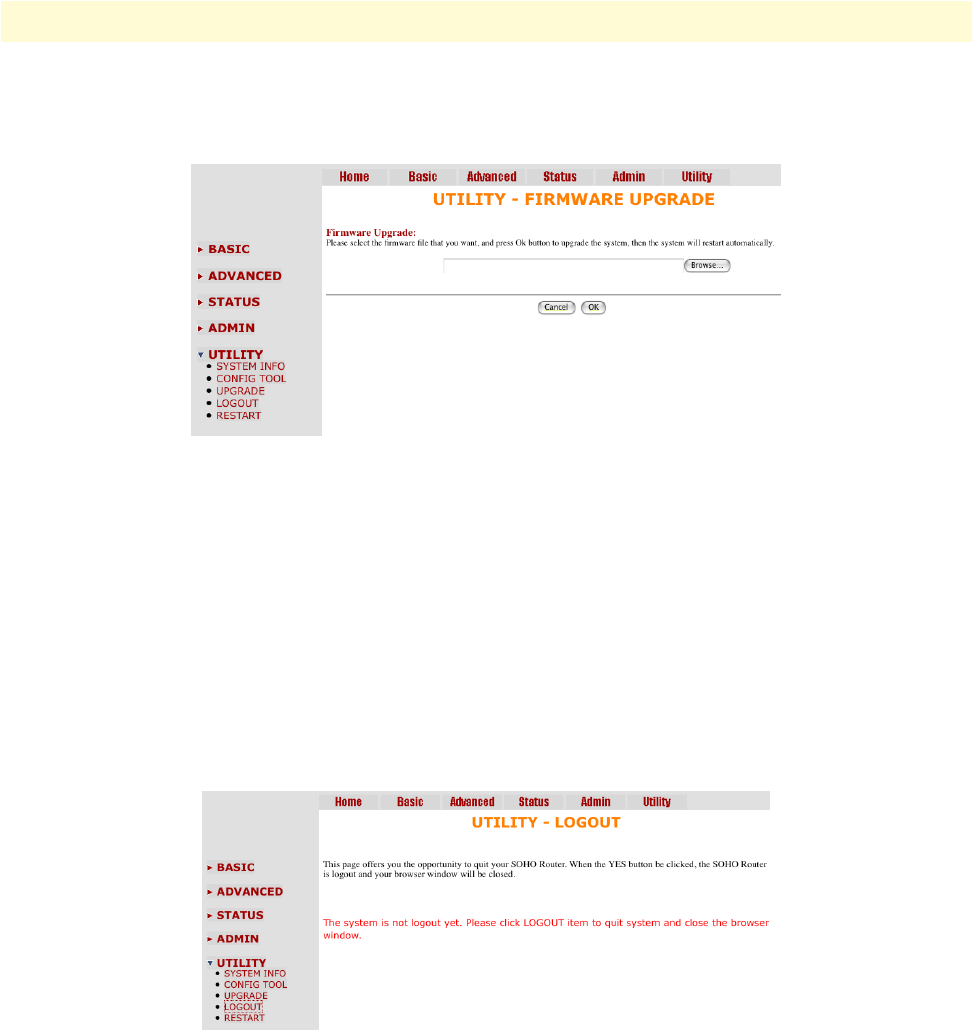
Utility Options 63
Model 3202 Getting Started Guide 4 • Web configuration
Upgrade
You can update the firmware of Model 3202 using the Upgrade function. Click Upgrade in the Utility menu.
Figure 42. Upgrade page
Type the path and file name of the Firmware file you wish to upload to the Model 3202 in text box. Or, you
can also click Browse to locate the file. Click OK to begin the upgrade process. The system will reboot auto-
matically after finishing. (Firmware upgrades will only take effect after the system reboots).
After the firmware upgrade process is complete, click System Info in the Utility menu to verify your current
firmware version number.
Logout
To exit the Model 3202 Web Management Interface securely, click Logout in the Utility menu. You have to
log in with your password again after you log out. This is recommended after you finish a management session
for security reasons.
Figure 43. Logout page
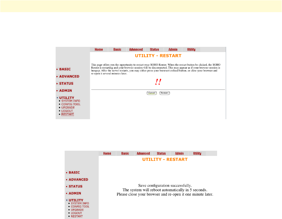
Utility Options 64
Model 3202 Getting Started Guide 4 • Web configuration
Restart
To reboot the Model 3202, click Restart in the Utility menu, then click the Restart button.
Figure 44. Restart page
The following screen displays:
Figure 45. Restart page

65
Chapter 5 Console and Telnet configuration
Chapter contents
Introduction..........................................................................................................................................................67
Log in to the console interface .........................................................................................................................67
Log in using Telnet .........................................................................................................................................67
Interface commands ........................................................................................................................................67
Window structure ...........................................................................................................................................68
Main Menu Tree...................................................................................................................................................69
Menu tree for authorized users ........................................................................................................................69
Menu tree for unauthorized users ....................................................................................................................70
Enable Command Menu .......................................................................................................................................71
Setup Command Menu.........................................................................................................................................72
G.SHDSL .......................................................................................................................................................72
Mode ........................................................................................................................................................73
Link ..........................................................................................................................................................73
Annex Type ...............................................................................................................................................73
TCPAM Type ...........................................................................................................................................73
Maximum Main Rate ................................................................................................................................73
SNR Margin .............................................................................................................................................73
Line Probe .................................................................................................................................................74
Clear .........................................................................................................................................................74
LAN ...............................................................................................................................................................74
VLAN .............................................................................................................................................................75
Mode ........................................................................................................................................................75
802.1Q VLAN.................................................................................................................................... 76
Port-Based VLAN ............................................................................................................................... 77
QoS ................................................................................................................................................................78
Mode ........................................................................................................................................................78
Queue Weight ...........................................................................................................................................79
Queue Schedule ........................................................................................................................................79
Port-Based Priority QoS ............................................................................................................................80
VLAN Tag Priority QoS ...........................................................................................................................80
IP DSCP Priority QoS ..............................................................................................................................81
List ............................................................................................................................................................82
Rate ................................................................................................................................................................82
MGMT ..........................................................................................................................................................83
DHCP ............................................................................................................................................................83
DHCP Server ............................................................................................................................................84
DHCP Fixed Host ....................................................................................................................................84
DNS Proxy .....................................................................................................................................................85
Host Name .....................................................................................................................................................85

66
Model 3202 Getting Started Guide 5 • Console and Telnet configuration
Factory Default ...............................................................................................................................................85
Status Command Menu ........................................................................................................................................86
G.SHDSL Status ............................................................................................................................................86
Interface Status ...............................................................................................................................................86
Show Command Menu .........................................................................................................................................87
Write Command ...................................................................................................................................................87
Reboot Command.................................................................................................................................................88
Ping Command .....................................................................................................................................................88
Administration Command Menu ..........................................................................................................................89
User Profile .....................................................................................................................................................89
Modify/Add User ......................................................................................................................................89
Security ...........................................................................................................................................................90
Telnet TCP Port .......................................................................................................................................90
Legal IP Address Pool ................................................................................................................................90
SNMP ............................................................................................................................................................91
Community ..............................................................................................................................................91
Trap host ..................................................................................................................................................92
Supervisor Password and ID ...........................................................................................................................93
Supervisor Password ..................................................................................................................................93
Supervisor ID ............................................................................................................................................93
Utility Command Menu........................................................................................................................................94
Upgrade main software ...................................................................................................................................94
Backup system configuration ..........................................................................................................................94
Restore system configuration ...........................................................................................................................94
Exit Command......................................................................................................................................................95
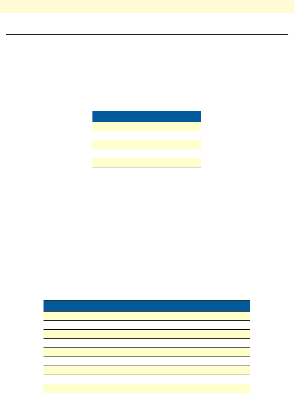
Introduction 67
Model 3202 Getting Started Guide 5 • Console and Telnet configuration
Introduction
This chapter provides information for configuring the Model 3202 by using the serial console with Telnet.
Log in to the console interface
The console port is a RJ-48C connector that provides a connection to a PC for monitoring and configuring
the Model 3202. Use the supplied serial cable with a female DB-9 connector to connect to the serial port of
PC, and connect the RJ-48C module jack connector to the Model 3202's console port. Start your terminal
emulation program (such as Hyper Terminal) and configure the communication parameters. Use the settings
shown in Table 15 to log into the console:
After you enter the settings for the console, press the spacebar until the login screen appears. When you see the
login screen, you can log on to the Model 3202. Enter admin for both the User Name and Password.
Log in using Telnet
The Model 3202 also supports Telnet for remote management. Connect the Ethernet cable to the MGMT
port of Model 3202 to your computer. The MGMT LED on the front panel of the Model 3202 will light up.
Start your Telnet client with VT100 terminal emulation and connect to the management IP of the Model
3202. Wait for the login prompt to display. Enter your user name and password. When you see the login
screen, you can log on to the Model 3202. Enter admin for both the User Name and Password.
Note The default IP address is 192.168.1.1. The line command is “telnet
192.168.1.1” in DOS mode.
Interface commands
Before changing the configuration, familiarize yourself with the operations list in the following table:
Table 15. Console settings
Parameter Value
Baud rate 9600
Data Bits 8
Parity Check None
Stop Bits 1
Flow-control None
Table 16. Interface commands
Keystroke Description
[UP] or I Move to the field above in the same level menu.
[DOWN] or K Move to field below in the same level menu.
[LEFT] or J Move back to the previous menu.
[RIGHT], L or [ENTER] Move forward to the submenu.
[HOME] or U Move to the first field.
[END] or O Move to the last field.
[TAB] Choose another parameter.
Ctrl + C Quit configuring the item.
Ctrl +Q Access help.
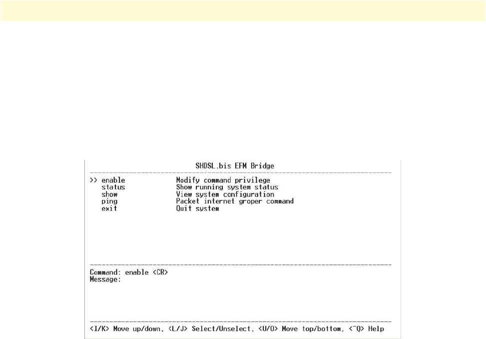
Introduction 68
Model 3202 Getting Started Guide 5 • Console and Telnet configuration
The Model 3202 uses a menu-driven interface for serial console and Telnet management. This interface dis-
plays all available commands for configuring the modem.
The following figure shows an example of the menu-driven interface. In the menu, scroll up/down by pressing
the I / K keys. Select one command by pressing the L key. Go back to a higher level of the menu by pressing
the J key. You can also scroll to the top/bottom with the U/O keys.
For example, to show the system information, log on to the Model 3202. Press the K key twice and select the
show command with the L key. Select the system command in the submenu. The system will display general
information. You may also use the Enter key to select a command.
Figure 46. Console/Telnet Menu
Window structure
From top to bottom, the window is divided into four parts:
•Product name: G.SHDSL EFM Bridge
•Menu field: The menu tree prompts on this field. Symbol “>>” indicates the cursor place.
•Configuration field: Configure the parameters in this field. < parameter > indicates the parameters you can
choose and < more…> indicates that there are more options in the submenu.
•Footer: Operation commands for help
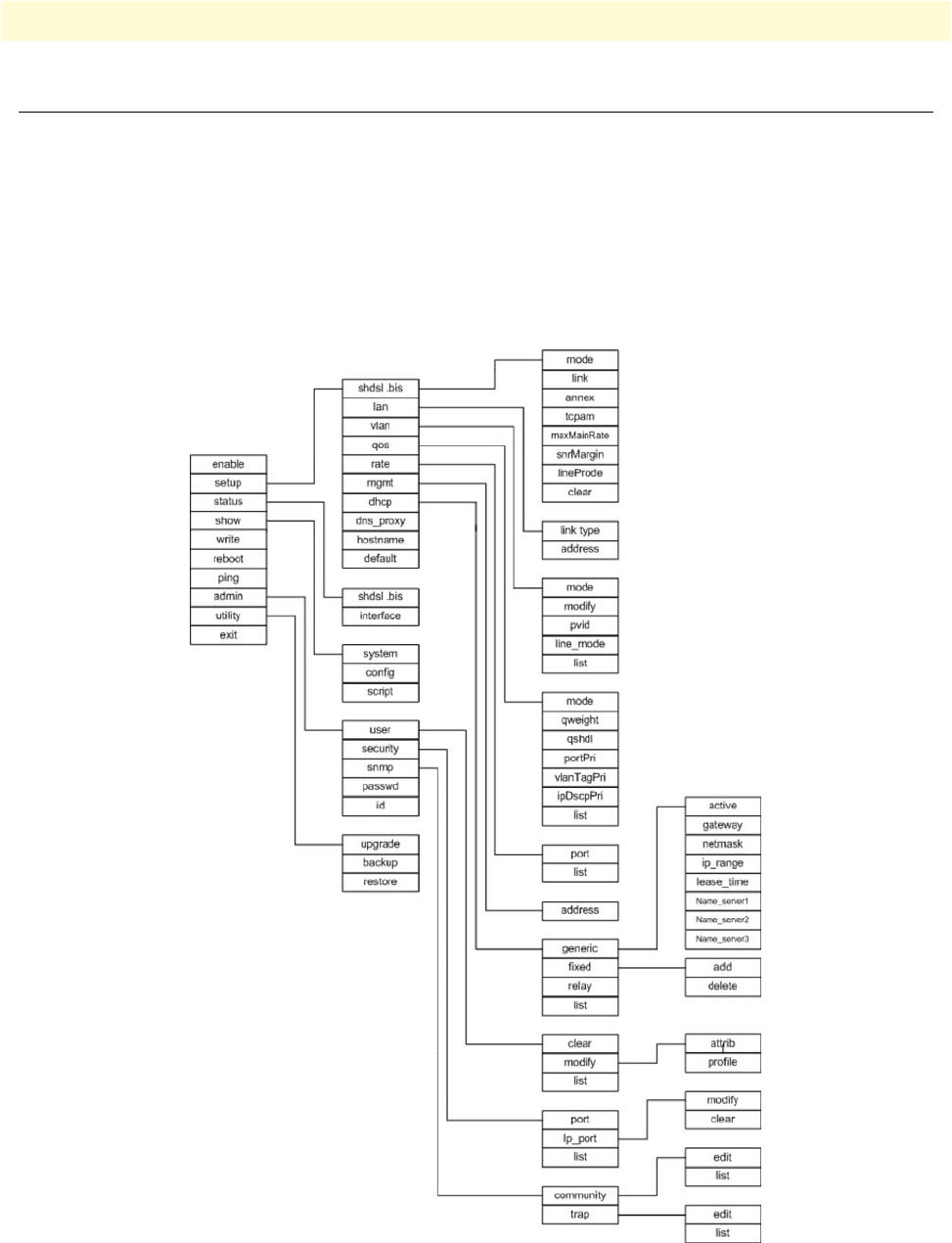
Main Menu Tree 69
Model 3202 Getting Started Guide 5 • Console and Telnet configuration
Main Menu Tree
The commands available in the main menu tree depend on if you have logged in using a supervisor password
(authorized user) or not (unauthorized user). An authorized user can access all of the configuration commands
in the subdirectories using the enable command. Unauthorized users cannot change any configurations but
can view the status and information for the Model 3202. They may also use the ping command to check the
Model 3202’s connection.
Menu tree for authorized users
Authorized users may log into the Model 3202 with a supervisor password to obtain access to all of the config-
uration commands.
Figure 47. Menu tree for authorized users
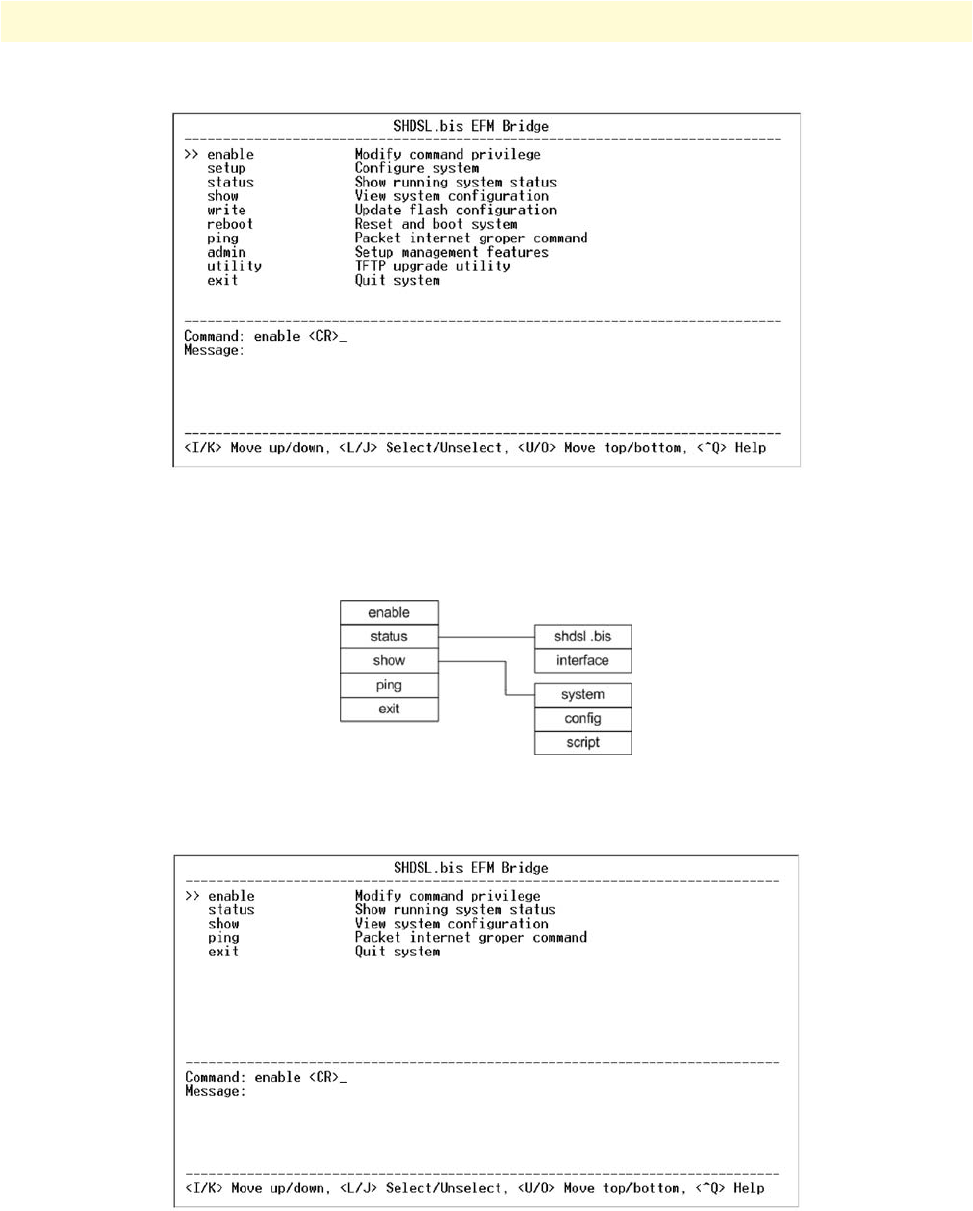
Main Menu Tree 70
Model 3202 Getting Started Guide 5 • Console and Telnet configuration
Figure 48. Main screen for authorized users
Menu tree for unauthorized users
Unauthorized users may access the following configuration commands for the Model 3202.
Figure 49. Main menu for unauthorized users
Figure 50. Main screen for unauthorized users
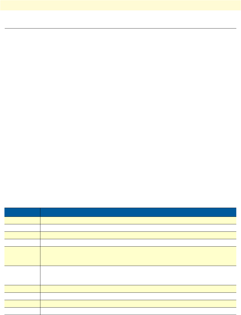
Enable Command Menu 71
Model 3202 Getting Started Guide 5 • Console and Telnet configuration
Enable Command Menu
The enable command menu lists commands for setting up the Model 3202. Move the cursor “ >>” to enable
and press Enter. Type the supervisor password, which is root.
----------------------------------------------------------------------
Command: enable <CR>
Message: Please input the following information.
Supervisor password: ****
----------------------------------------------------------------------
In the enable sub menu, you can set up management features and upgrade software, back up the system config-
uration and restore the system configuration via utility tools.
To save your changes, you must write the new configuration to NVRAM and reboot the Model 3202 to work
with the new settings.
When you first log in to the Model 3202 with the supervisor password, the main menu displays:
Table 17 explains the commands available in the main menu:
>>
enable Modify command privilege
setup Configure system
status Show running system status
show View system configuration
write Update flash configuration
reboot Reset and boot system
ping Packet internet groper command
admin Setup management features
utility TFTP upgrade utility
exit Quit system
Table 17. Enable Command Menu
Command Description
enable Change the configuration and write changes to nonvolatile RAM (NVRAM).
setup Initially configure the Model 3202.
status View the status of the Model 3202
show Show the system and configuration
write Update flash configuration. After you have completed all desired changes, make sure to
write the new configuration to NVRAM. Use the write command to save your changes
and reboot the system or all of your changes will not take effect.
reboot Reset and reboot system. After you have completed all desired changes, make sure to write
the new configuration to NVRAM. Use the reboot command to restart the system or all of
your changes will not take effect.
ping Check the connection to the Model 3202
admin Set up advanced management features
utility Upgrade software and backup/restore the current configuration
exit Log out of the system

Setup Command Menu 72
Model 3202 Getting Started Guide 5 • Console and Telnet configuration
Setup Command Menu
The setup command menu lists commands for initially configuring the Model 3202. Move the cursor “ >>” to
setup in the main menu and press Enter.
When you enter the setup command, the following menu displays:
G.SHDSL
The g.shdsl command menu lists commands for setting up the DSL port. Move the cursor “ >>” to g.shdsl in
the setup menu and press Enter. The following menu displays:
Table 18 shows the options available within the g.shdsl command menu:
>>
g.shdsl Configure g.shdsl parameters
lan Configure LAN interface profile
vlan Configure virtual LAN parameters
qos Configure Quality of Service parameters
rate Configure Rate Control parameters
mgmt Configure management interface profile
dhcp Configure DHCP parameters
dns_proxy Configure DNS proxy parameters
hostname Configure local host name
default Restore factory default settings
>>
mode Configure g.shdsl mode
link Configure g.shdsl link
annex Configure g.shdsl annex type
tcpam Configure g.shdsl TCPAM type
maxMainRate Configure g.shdsl max main data rate
snrMargin Configure g.shdsl SNR margin
lineProbe Configure g.shdsl line probe
clear Clear current CRC error count
Table 18. G.SHDSL Options
Menu Options
Mode STU-C STU-R
Link Type 2-wire 4-wire 8-wire
Annex AF BG
TCPAM Auto TCPAM-16 TCPAM-32 TCPAM-64
Max Main Rate (3–177)
SNR Margin (-10–21)
Line Probe Disable Enable
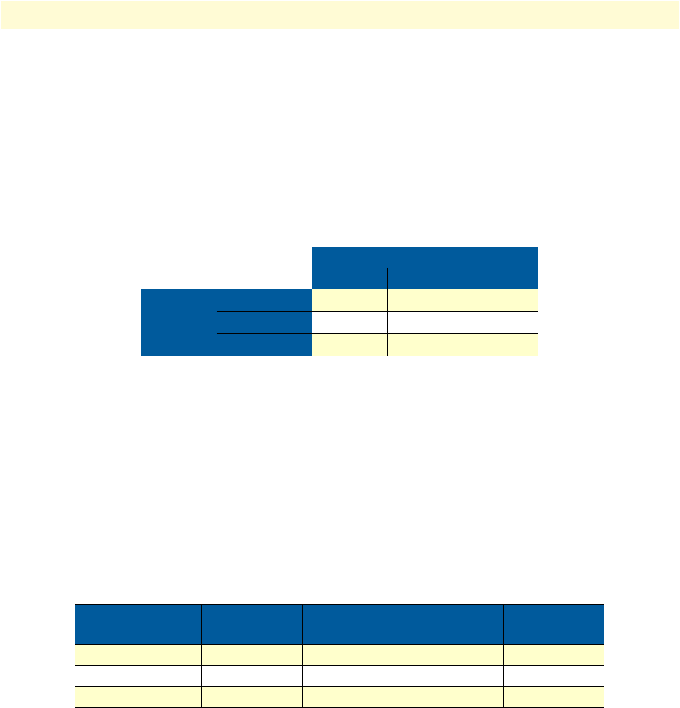
Setup Command Menu 73
Model 3202 Getting Started Guide 5 • Console and Telnet configuration
Mode
There are two types of G.SHDSL mode:
•STU-C: Central Office (CO) terminal
•STU-R: Customer Premise Equipment (CPE)
Link
Select the line type for your model. Line type means how many wires you want to use on the DSL connection.
For example, you can select 2-wire, 4-wire or 8-wire line type for the 8-wire model.
Annex Type
Enter the appropriate Annex type. Annex AF describes the transmission and performance requirements for
North America. Annex BG describes performance and transmission requirements for Europe.
TCPAM Type
TCPAM (Trellis Coded Pulse Amplitude Modulation) is the standard used for line coding. Select the TCPAM
type. Auto is the default option for TCPAM.
Maximum Main Rate
Select the DSL rate for your model. The main rate is the multiple of 64kbps, 128kbps, or 256kpbs- depending
on your model type. Use Table 20 to determine the best main rate for your model.
SNR Margin
SNR margin is an index of line connection quality. Generally, you won’t need to change the SNR Margin. You
can view the actual SNR margin in status command menu.You will experience better line connection quality
for larger SNR margin values.
For example, if you set the SNR margin ias 5, the DSL connection will drop and reconnect when the SNR
margin is lower than 5. On the other hand, the device will reduce the line rate and reconnect for better line
connection quality. You may select the SNR margin from the range -10 to 21.
Table 19. Line Type Chart
Line Type
2-wire 4-wire 8-wire
Model
Type
2-wire model •
4-wire model • •
8-wire model •••
Table 20. Main Rate Chart
Model Type Multiple TCPAM-16
= 3–60
TCPAM-32
= 12–89
TCPAM-64
= 90–177
2-wire model 64 192–3840 768–5696 5760-11328
4-wire model 128 384–7680 1536–11392 11520-22656
8-wire model 256 768–15360 3072–22784 23040-45312

Setup Command Menu 74
Model 3202 Getting Started Guide 5 • Console and Telnet configuration
Line Probe
For adaptive mode applications, set the Line Probe to Enable. The Model 3202 will adapt the data rate accord-
ing to the line status. For all other applications, set the Line Probe to Disable.
Clear
Use the clear command to reset the CRC error count.
LAN
The lan command menu lists commands for setting up the LAN ports. Move the cursor “ >>” to lan in the
setup menu and press Enter.
-----------------------------------------------------------------------------
Command: setup lan <1~1>
Message: Please input the following information.
Interface number <1~1>: 1
-----------------------------------------------------------------------------
The default interface number is 1.
You can configure the Link type, LAN IP address and subnet mask for the LAN interface.
Table 21 shows the options available within the lan command menu:
-----------------------------------------------------------------------------
Command: setup lan 1 link_type <Disable|Dynamic|Static>
Message: Please input the following information.
Link type (TAB Select) <Disable>:
-----------------------------------------------------------------------------
Select the lan 1 link_type as Disable, Dynamic or Static. Then, select address from the lan menu:
-----------------------------------------------------------------------------
Command: setup lan 1 address <ip> <netmask>
Message: Please input the following information.
IP address (ENTER for default) <192.168.2.1>:
Subnet mask (ENTER for default) <255.255.255.0>:
-----------------------------------------------------------------------------
Set the LAN IP address and subnet mask. The default IP Address is 192.168.2.1 and the default subnet mask
is 255.255.255.0.
>>
link_type Configure Link type
address LAN address and subnet mask
Table 21. LAN Options
Menu Options
Link Type Disable Dynamic Static
IP Address
Subnet Mask

Setup Command Menu 75
Model 3202 Getting Started Guide 5 • Console and Telnet configuration
VLAN
Virtual LAN (VLAN) is defined as a group of devices on one or more LANs that are configured so that they
can communicate as if they were attached to the same wire, when in fact they are located on a number of dif-
ferent LAN segments. Because VLAN is based on logical instead of physical connections, it is extremely flexi-
ble.
You can setup the Virtual LAN (VLAN) parameters in VLAN command. The Model 3202 supports VLAN-
to-PVC only for bridge mode operation, i.e., the VLAN spreads over both the CO and CPE sides, where there
is no layer 3 routing involved. The unit supports up to 8 active VLANs with shared VLAN learning (SVL)
bridge out of 4096 possible VLANs specified in IEEE 802.1Q.
The vlan command menu lists commands for setting up the DSL port. Move the cursor “ >>” to vlan in the
setup menu and press Enter. The following menu displays:
To activate the VLAN function, move the cursor “ >> “ to mode and press Enter. The products support two
types of VLAN: 802.1Q and Port-Based.
802.1Q defines the operation of VLAN bridges that permit the definition, operation, and administration of
VLAN topologies within a bridged LAN infrastructure. Port-Based VLANs are VLANs where the packet for-
warding decision is based on the destination MAC address and its associated port.
Mode
You can choose from two types of VLANs: 802.1Q Tag-Based VLAN or Port Based VLAN. If you are not
going to use the VLAN function, set this option to Disable.
-----------------------------------------------------------------------------
Command: setup vlan mode <Disable|8021Q|Port>
Message: Please input the following information.
Trigger VLAN function (TAB Select) <Disable>:
-----------------------------------------------------------------------------
Table 22 shows the options available within the VLAN mode command menu:
>>
mode Trigger virtual LAN function
modify Modify virtual LAN table
pvid Modify port default VID
link_mode Modify port link type
list Show VLAN configuration
Table 22. VLAN Mode Options
Menu Options
VLAN Mode Disable 802.1Q Tag VLAN Port-Based VLAN

Setup Command Menu 76
Model 3202 Getting Started Guide 5 • Console and Telnet configuration
802.1Q VLAN. To modify the VLAN rule, move the cursor to modify and press Enter.
-----------------------------------------------------------------------------
Command: setup vlan modify <1~8> <0~4094> <string>
Message: Please input the following information.
VLAN table entry index <1~8>: 1
VID value (ENTER for default) <1>: 10
VLAN port membership (ENTER for default) <111111>:
-----------------------------------------------------------------------------
The VLAN Port membership ris represented with 1 or 0. VLAN port membership is a 6-digit binary number
in which bit 0 to bits 5 represent LAN1 to LAN4, DSL and Sniffing ports respectively.
For example: [
setup vlan modify 1 10 111111
] means use index as 1 , VID = 10 and all six ports are the same
membership (VLAN ID=10).
Use the pvid command to change the member port to untagged members:
-----------------------------------------------------------------------------
Command: setup vlan pvid <1~6> <1~4094>
Message: Please input the following information.
Port index <1~6>:
VID value (ENTER for default) <1>:
-----------------------------------------------------------------------------
PVID (Port VID) is an untagged member from 1 to 4094 for the default VLAN.
For example:
[ set vlan pvid 1 100]
[ set vlan pvid 2 100]
[ set vlan pvid 3 100]
[ set vlan pvid 4 100]
[ set vlan pvid 5 100]
[ set vlan pvid 6 100]
This example shows that all untagged members of all ports all have the same membership (VLAN ID=100).
To modify the link type of the port, move the cursor to link_mode and press Enter. There are two types of link:
access and trunk. A Trunk link will send the tagged packet form the port. An Access link will send an
untagged packet from the port. The port index 1 to 4 represents LAN ports. Index 5 represents DSL, and
index 6 represents Sniffing.
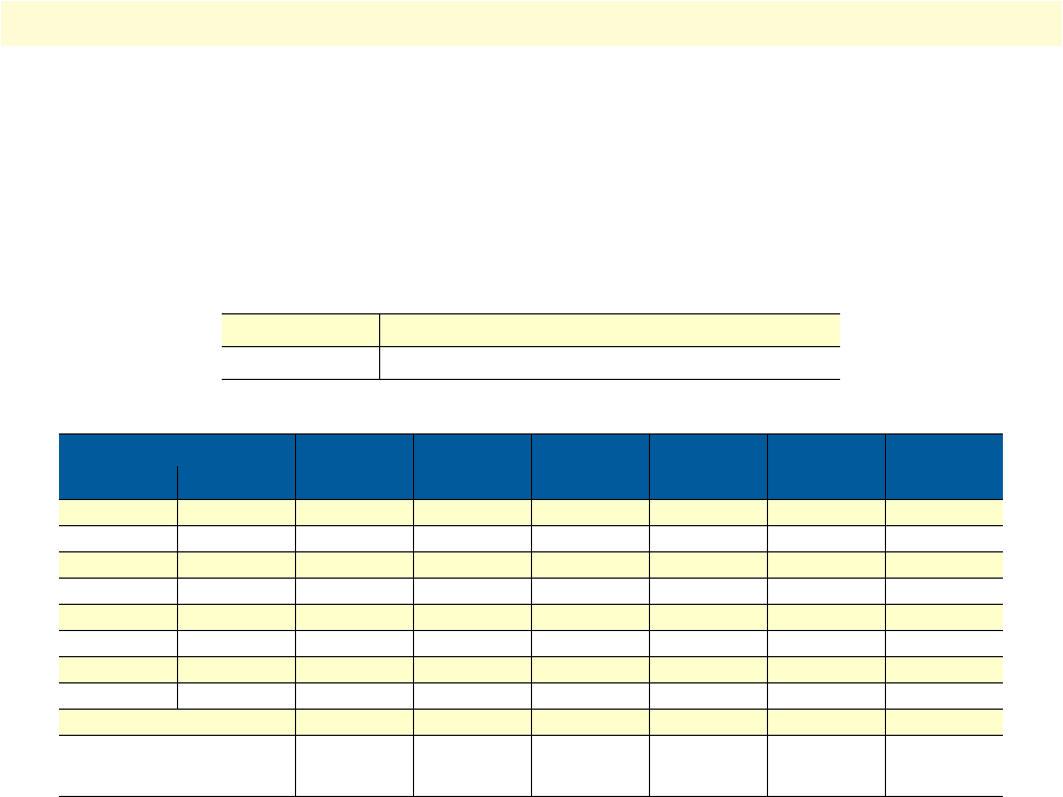
Setup Command Menu 77
Model 3202 Getting Started Guide 5 • Console and Telnet configuration
-----------------------------------------------------------------------------
Command: setup vlan link_mode <1~6> <Access|Trunk>
Message: Please input the following information.
Port index <1~6>: 1
Port link type (TAB Select) <Access>:
-----------------------------------------------------------------------------
Table 23 shows the options available within the 802.1Q Tag VLAN command menu:
Port-Based VLAN. With port-based VLAN, the port is assigned to a specific VLAN independent of the user
or system attached to the port. This means all users attached to the port should be members in the same
VLAN. The network administrator typically performs the VLAN assignment. The port configuration is static
and cannot be automatically changed to another VLAN without manual reconfiguration.
You can set up Port-Based VLAN using the method for 802.11Q. However, VID , PVID or link type do not
matter for Port-Based VLAN. Use the list command to check the status of the VLAN.
-----------------------------------------------------------------------------
Virtual LAN Parameter
VLAN Mode : Port-Based VLAN
Virtual LAN Table
No LAN1 LAN2 LAN3 LAN4 DSL Sniffing
-- ---- ---- ---- ---- ---- --------
1 1 1 1 1 1 1
2 - - - - - -
3 - - - - - -
4 - - - - - -
5 - - - - - -
6 - - - - - -
7 - - - - - -
8 - - - - - -
-----------------------------------------------------------------------------
Access The port can receive or send untagged packets.
Trunk The port can receive or send tagged packets.
Table 23. 802.1Q VLAN Options
1 2 3 4 5 6
No. VID LAN1 LAN2 LAN3 LAN4 DSL Sniffing
1
2
3
4
5
6
7
8
PVID
Link Type Access
Trunk
Access
Trunk
Access
Trunk
Access
Trunk
Access
Trunk
Access
Trunk

Setup Command Menu 78
Model 3202 Getting Started Guide 5 • Console and Telnet configuration
QoS
Quality of Service (QoS) refers to both a network's ability to deliver data with minimum delay, and the net-
working methods used to control the use of bandwidth. Without QoS, all traffic date is equally likely to be
dropped when the network is congested. This can cause a reduction in network performance and mark the net-
work inadequate for a time-critical application such as video-on-demand.
The qos command menu lists commands for managing traffic. Move the cursor “ >>” to qos in the setup menu
and press Enter. The following menu displays:
Mode
You can choose from three types of QoS: Port-Based, VLAN Tag, and IP DSCP. If you are not going to use
the QoS function, set this option to Disable.
-----------------------------------------------------------------------------
Command: setup qos mode <Disable|PortBased|VlanTag|IpDscp>
Message: Please input the following information.
Trigger qoS function (TAB Select) <Disable>:
-----------------------------------------------------------------------------
Table 24 shows the options available within the QoS mode command menu:
>>
mode Trigger Quality of Service function
qweight Modify queue weight
qSchdl Modify queue schedule type
portPri Modify port priority
vlanTagPri Modify VLAN TAG priority
ipDscpPri Modify IP DSCP priority
list Show QoS configuration
Table 24. VLAN Mode Options
Menu Options
QoS Mode Disable Port-Based VLAN Tag IP DSCP
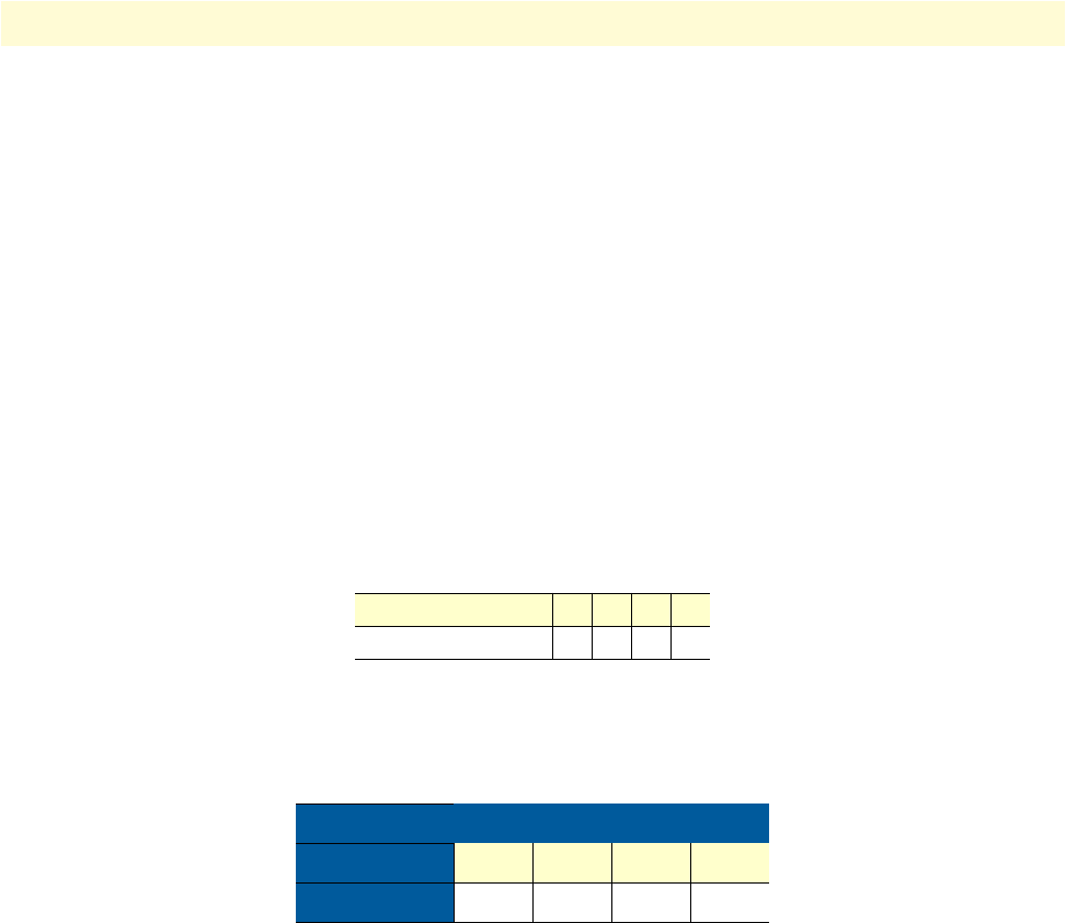
Setup Command Menu 79
Model 3202 Getting Started Guide 5 • Console and Telnet configuration
Queue Weight
This setting configures the weight value for each queue.
-----------------------------------------------------------------------------
Command: setup qos qweight <0~3> <1~15>
Message: Please input the following information.
Queue index <0~3>: 0
Weight value (ENTER for default) <1>: 1
-----------------------------------------------------------------------------
For example, the default values are shown below:
[ setup qos qweight 0 1]
[ setup qos qweight 1 2]
[ setup qos qweight 2 4]
[ setup qos qweight 3 8]
Queue Schedule
There are two types of queue schedule. Select from Type 1 or Type 2. Table explains the schedule types:
-----------------------------------------------------------------------------
Command: setup qos qSchdl <Type1|Type2|>
Message: Please input the following information.
Operation type (TAB Select) <Type1>: Type1
-----------------------------------------------------------------------------
The Queue types are Weight Round Robin (WRR), Best Effort (BE), and Strictly Priority (SP).
•WRR services on a rotating basis and is activated only when a port has more traffic than it can handle. A
queue is a given an amount of bandwidth irrespective of the incoming traffic on that port. The queue then
moves to the back of the list. The next queue is given an equal amount of bandwidth, and then moves to the
end of the list, and so on, depending on the number of queues being used, This works in a looping fashion
until a queue is empty.
•BE is used for data applications or any non-classified traffic. This would include e-mail, Internet browsing,
data back-up etc. The BE class is for traffic that can afford to wait and not affect the overall outcome of the
data application.
Table 25. Queue Weight Options
QoS Mode 0 1 2 3
Weight Value
Table 26. Queue Schedule Types
Queue 0 1 2 3
Type 1 WRR WRR WRR WRR
Type 2 BE BE BE SP
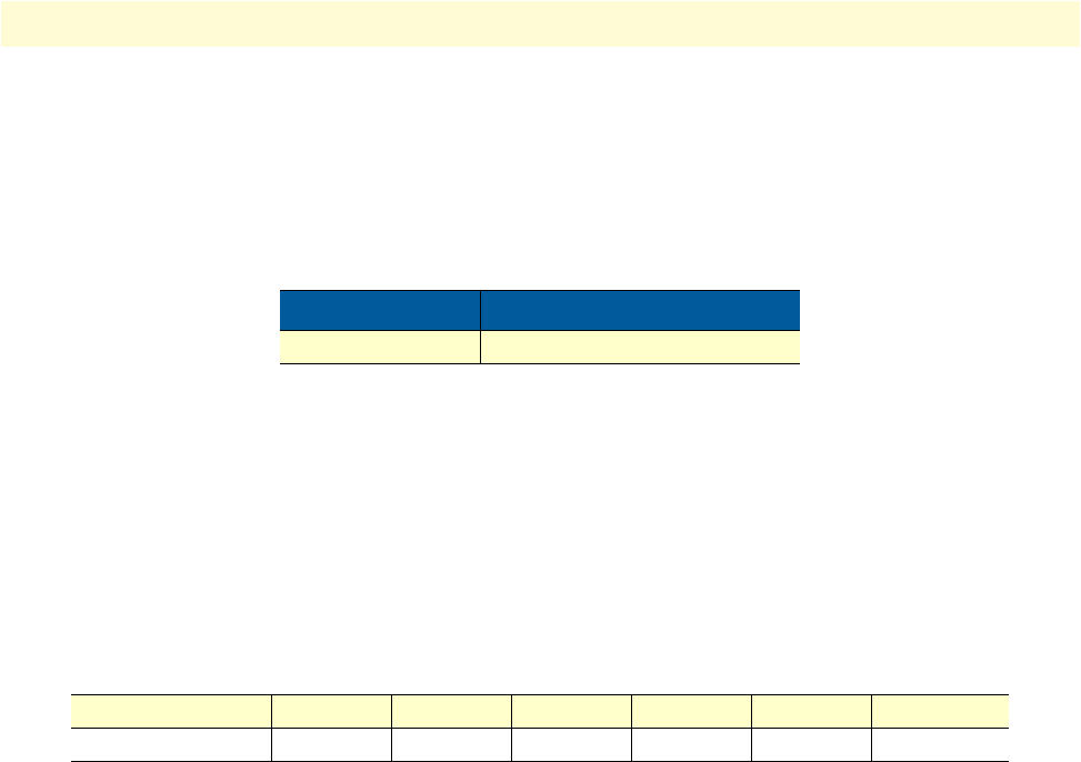
Setup Command Menu 80
Model 3202 Getting Started Guide 5 • Console and Telnet configuration
•SP services queues based on priority only. As traffic comes into the Model 3202, traffic on the highest prior-
ity queue, Q3 is transmitted first. When that queue empties, traffic on the next highest-priority queue, Q2
transmitted until Q2 empties, and then traffic is transmitted on Q1 and so on. If higher priority queues
never empty, then traffic on lower priority never gets sent. The SP class is typically for video applications
that require a fixed amount of bandwidth to be considered good quality.
Port-Based Priority QoS
-----------------------------------------------------------------------------
Command: setup qos portPri <1~6> <0~3>
Message: Please input the following information.
Port index <1~6>: 1
Queue index (ENTER for default) <3>: 3
-----------------------------------------------------------------------------
Set up the queue value (0, 1, 2 or 3) on each port.
VLAN Tag Priority QoS
----------------------------------------------------------------------------
Command: setup qos vlanTagPri <0~7> <0~3>
Message: Please input the following information.
VLAN TAG index <0~7>: 0
Queue index (ENTER for default) <1>: 1
-----------------------------------------------------------------------------
Set up the queue index (0, 1, 2 or 3) on Priority VLAN Tag.
VLAN Tag Priority uses the tag field information which has been inserted into an Ethernet frame. If a port has
an 802.1Q-compliant device attached (such as this modem), these tagged frames can carry VLAN membership
information.
Priority defines the user priority level for different classes of traffic. There are 8 possible priority levels, with 0
being the lowest priority level and 7 being the highest level. Each Priority level can be set queue from 0 to 3.
Table 27. Queue Schedule Options
Menu Options
Queue Schedule Type 1 Type 2
Table 28. Port-Based Priority QoS Options
Port 1 (LAN1) 2 (LAN2) 3 (LAN3) 4 (LAN4) 5 (DSL) 6 (Sniffing)
Queue Index
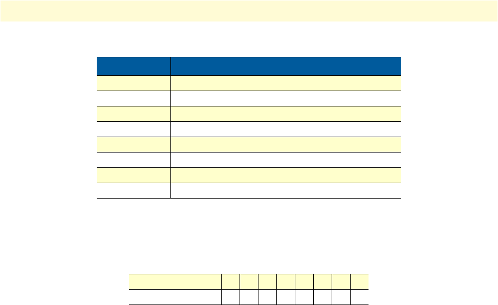
Setup Command Menu 81
Model 3202 Getting Started Guide 5 • Console and Telnet configuration
For example, you can set the Model 3202 to use Weighted Round-Robin (WRR) queuing (Type 1) that speci-
fies a relative weight of each queue. WRR uses a predefined relative weight for each queue that determines the
percentage of s time to services for each queue before moving on to the next queue.
IP DSCP Priority QoS
Differentiated Services (DiffServ) is a class of service (CoS) model that enhances best-effort Internet services by
differentiating traffic by users, service requirements and other criteria. Packets are specifically marked, allowing
network nodes to provide different levels of service, as appropriate for video playback, voice calls or other
delay-sensitive applications, via priority queuing or bandwidth allocation.
The DSCP value used to identify 64 levels (26=64) of service determines the forwarding behavior that each
packet gets across the DiffServ network. Based on the marking rule different kinds of traffic can be marked for
different priorities of forwarding. Resources can then be allocated according to the DSCP values and the con-
figured policies.
Set up queue index (0, 1, 2 or 3) on each DSCP:
-----------------------------------------------------------------------------
Command: setup qos ipDscpPri <0~63> <0~3>
Message: Please input the following information.
IP DSCP index <0~63>: 0
Queue index (ENTER for default) <0>:
-----------------------------------------------------------------------------
Table 29. VLAN Tag Priority Levels
Priority Level Traffic Type
0 (default) Best Effort
1Background
2Spare
3Excellent Effort
4Controlled Load
5Video, less than 100 milliseconds latency and jitter
6Voice, less than 10 milliseconds latency and jitter
7Network Control
Table 30. VLAN Tag Priority QoS Options
VLAN Tag Index 0 1 2 3 4 5 6 7
Queue Index
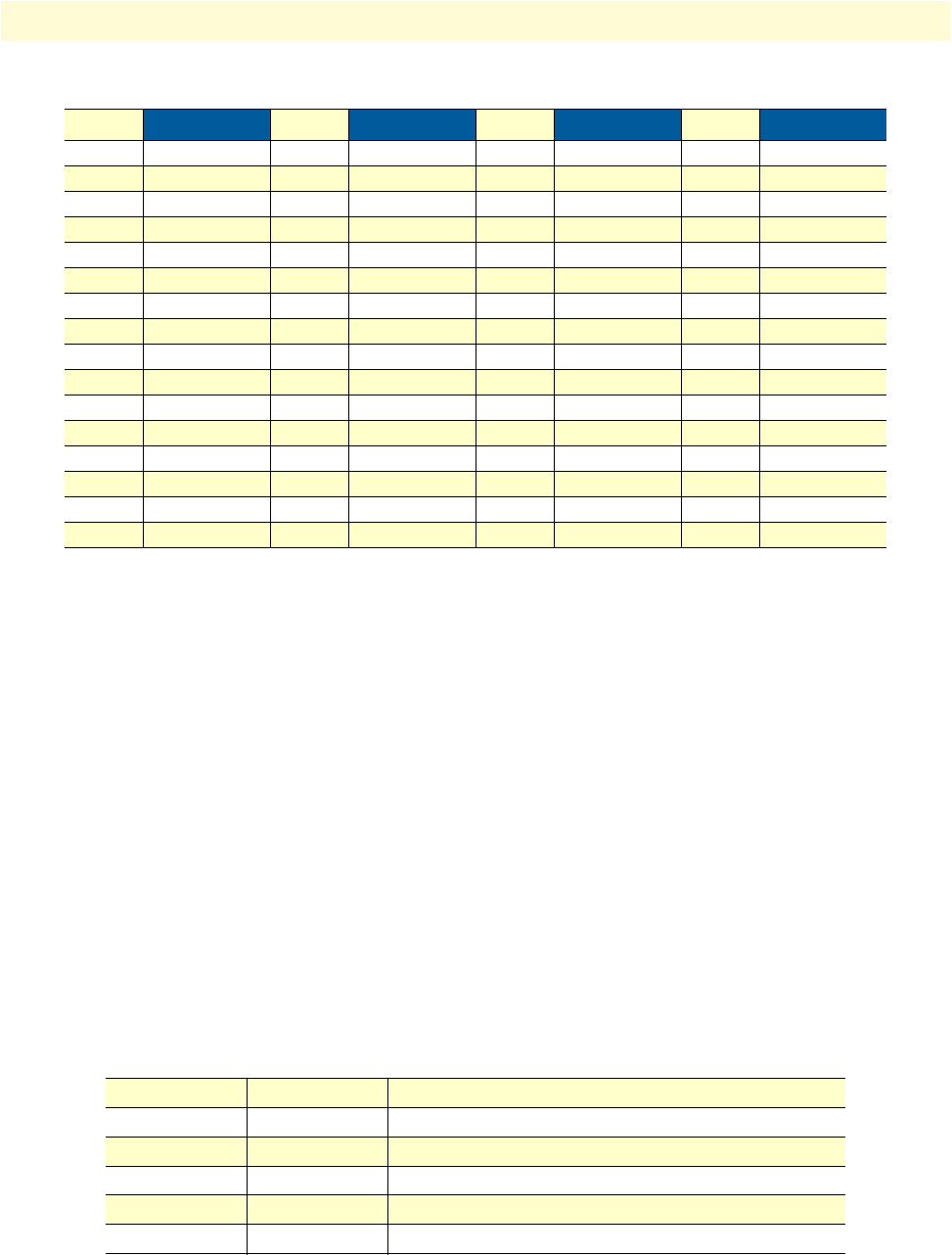
Setup Command Menu 82
Model 3202 Getting Started Guide 5 • Console and Telnet configuration
List
Use the list command to view the QoS settings.
Rate
The rate command menu lists commands for setting the port rate. Move the cursor “ >>” to rate in the setup
menu and press Enter. The following menu displays:
Select the port you want to modify, then set up the data rate.
-----------------------------------------------------------------------------
Command: setup rate port <1~6> <no_limit|128K|256K|512K|1M|2M>
Message: Please input the following information.
Port index <1~6>: 1
rate (TAB Select) <no_limit>:
-----------------------------------------------------------------------------
Table 32 shows the options available to set up the data rate:
Table 31. IP DSCP Priority QoS Options
DSCP Queue Index DSCP Queue Index DSCP Queue Index DSCP Queue Index
0 16 32 48
1 17 33 49
2 18 34 50
3 19 35 51
4 20 36 52
5 21 37 53
6 22 38 54
7 23 39 55
8 24 40 56
9 25 41 57
10 26 42 58
11 27 43 59
12 28 44 60
13 29 45 61
14 30 46 62
15 31 47 63
>>
port Modify port rate
list Show Rate Control configuration
Table 32. Rate Options
Port 1 LAN1 No Limit 128K 256K 512K 1M
Port 2 LAN2 No Limit 128K 256K 512K 1M
Port 3 LAN3 No Limit 128K 256K 512K 1M
Port 4 LAN4 No Limit 128K 256K 512K 1M
Port 5 DSL No Limit 128K 256K 512K 1M
Port 6 Sniffing No Limit 128K 256K 512K 1M

Setup Command Menu 83
Model 3202 Getting Started Guide 5 • Console and Telnet configuration
MGMT
The mgmt command menu lists commands for configuring the IP address and subnet mask for the MGMT
port. Move the cursor “ >>” to mgmt in the setup menu and press Enter. The following menu displays:
----------------------------------------------------------------------
Command: setup mgmt <1~1> <more...>
Message: Please input the following information.
Interface number <1~1>:
----------------------------------------------------------------------
The Model 3202 only has one MGMT interface. The default interface number is 1. The default IP address and
subnet mask are 196.168.1.1 and 255.255.255.0 .
----------------------------------------------------------------------
Command: setup mgmt 1 address <ip> <netmask>
Message: Please input the following information.
IP address (ENTER for default) <192.168.1.1>:
Subnet mask (ENTER for default) <255.255.255.0>:
----------------------------------------------------------------------
DHCP
Dynamic Host Configuration Protocol (DHCP) is a communication protocol that allows network adminis-
trators to manage and automate the assignment of Internet Protocol (IP) addresses in an organization's net-
work. Each machine that can connect to the Internet needs a unique IP address. When an organization sets up
the users with a connection to the Internet, an IP address must be assigned to each machine.
Without DHCP, the IP address must be entered manually at each computer. If computers move to another
location in another part of the network, a new IP address must be entered. DHCP lets a network administrator
supervise and distribute IP addresses from a central point and automatically sends a new IP address when a
computer is plugged into a different place in the network.
>>
address MGMT IP address and subnet mask

Setup Command Menu 84
Model 3202 Getting Started Guide 5 • Console and Telnet configuration
DHCP Server
The dhcp command menu lists commands for configuring DHCP settings. Move the cursor “ >>” to dhcp in
the setup menu and press Enter. The following menu displays:
The generic command menu lists commands for configuring general DHCP settings. Move the cursor “ >>” to
generic in the dhcp menu and press Enter. The following menu displays:
DHCP Fixed Host
The dhcp command menu lists commands for configuring DHCP settings. Move the cursor “ >>” to dhcp in
the setup menu and press Enter. The following menu displays:
The fixed command menu lists commands for configuring a Fixed Host IP Address list. Move the cursor “ >>”
to fixed in the dhcp menu and press Enter. The following menu displays:
When using the fixed host entry function, you must enter the MAC address and IP address at the same time.
You can configure up to 10 maximum fixed host IP addresses.
Use the list command to view the DHCP configuration.
>>
generic DHCP server generic parameters
fixed DHCP server fixed host IP list
list Show DHCP configuration
>>
active Trigger DHCP server function
gateway Default gateway for DHCP client
netmask Subnet mask for DHCP client
ip_range Dynamic assigned IP address range
lease_time Configure max lease time
name_server1 Domain name server1
name_server2 Domain name server2
name_server3 Domain name server3
generic DHCP server generic parameters
>>
fixed DHCP server fixed host IP list
list Show DHCP configuration
>>
add Add a fixed host entry
delete Delete a fixed host entry

Setup Command Menu 85
Model 3202 Getting Started Guide 5 • Console and Telnet configuration
DNS Proxy
The dns_proxy command allows you to set up three DNS servers for the Model 3202. Move the cursor “ >>”
to dns_proxy in the setup menu and press Enter.
----------------------------------------------------------------------
Command: setup dns_proxy <IP> [IP] [IP]
Message: Please input the following information.
DNS server 1 (ENTER for default) <168.95.1.1>: 10.0.10.1
DNS server 2: 10.10.10.1
DNS server 3:
----------------------------------------------------------------------
Host Name
A Host Name is a unique name that attaches a host to a network. The hostname is used to identify a particular
host in various forms of electronic communication. Some ISP providers require the Host Name as identifica-
tion. You may check with your ISP to see if your Internet service has been configured with a host name. In
most cases, you can ignore this field.
Move the cursor “ >>” to hostname in the setup menu and press Enter. The host name cannot use spaces and
cannot have more than 15 characters.
----------------------------------------------------------------------
Command: setup hostname <name>
Message: Please input the following information.
Local hostname (ENTER for default) <SOHO>: test
----------------------------------------------------------------------
Factory Default
If you want to restore factory default settings for the Model 3202, move the cursor “ >>” to default in the
setup menu and press Enter.
----------------------------------------------------------------------
Command: setup default <name>
Message: Please input the following information.
Are you sure? (Y/N): y
----------------------------------------------------------------------
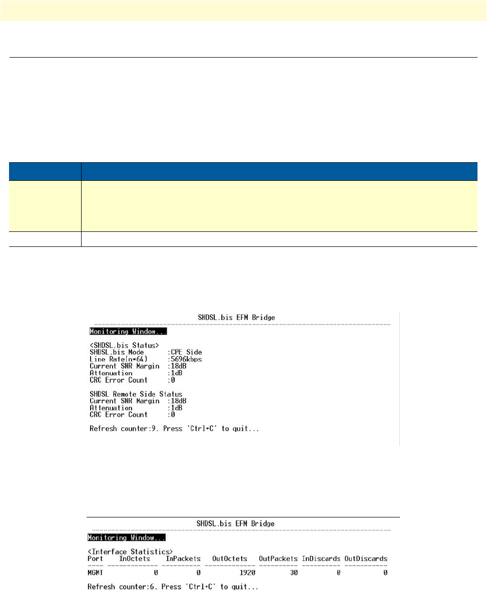
Status Command Menu 86
Model 3202 Getting Started Guide 5 • Console and Telnet configuration
Status Command Menu
The status command menu lists commands for viewing the system status of interfaces on the Model 3202.
Move the cursor “ >>” to status in the main menu and press Enter.
When you enter the status command, the following menu displays:
G.SHDSL Status
The g.shdsl command shows the status of the DSL port. Move the cursor “ >>” to g.shdsl in the status menu
and press Enter. The G.SHDSL status includes mode, line rate, SNR margin, attenuation, and CRC error
count of the local side modem, and SNR margin, attenuation and CRC error count of the remote side modem.
Figure 51. G.SHDSL Status
Interface Status
To view the status of the MGMT interface, move the cursor “ >>” to interface in the status menu and press
Enter.
Figure 52. Interface Status
>>
g.shdsl Show g.shdsl status
interface Show interface statistics status
Table 33. Status Command Menu
Command Description
g.shdsl The G.SHDSL status includes mode, line rate, SNR margin, attenuation, and CRC error
count of the local side modem, and SNR margin, attenuation and CRC error count of
remote side modem. The modem can access remote side information via EOC (embedded
operation channel).
interface Use the interface command to view the statistic status of the MGMT interface.
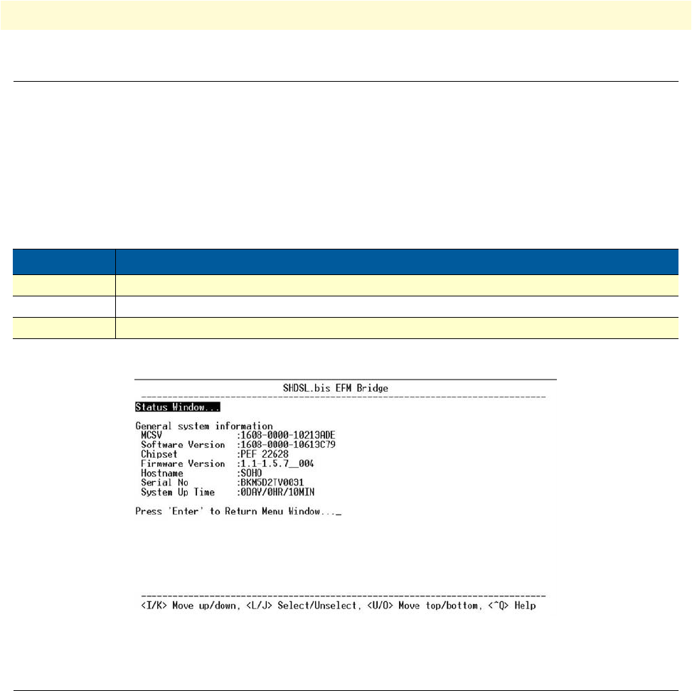
Show Command Menu 87
Model 3202 Getting Started Guide 5 • Console and Telnet configuration
Show Command Menu
The show command menu lists commands for viewing system and configuration information for the Model
3202. Move the cursor “ >>” to show in the main menu and press Enter.
When you enter the show command, the following menu displays:
Move the cursor “ >>” to system in the show menu and press Enter.
Figure 53. System Information
Write Command
The write command saves all new configuration changes to Flash on the Model 3202. You must use the write
command and reboot the modem for new configuration changes to tak effect. Move the cursor “ >>” to write
in the main menu and press Enter.
----------------------------------------------------------------------
Command: write <CR>
Message: Please input the following information.
Are you sure? (y/n): y
----------------------------------------------------------------------
>>
system Show general information
config Show all configuration
script Show all configuration in command script
Table 34. Show Command Menu
Command Description
system Displays general system information
config Displays detailed configuration information
script Displays configuration information in command script

Reboot Command 88
Model 3202 Getting Started Guide 5 • Console and Telnet configuration
Reboot Command
The reboot command restarts the Model 3202. Move the cursor “ >>” to reboot in the main menu and press
Enter.
----------------------------------------------------------------------
Command: reboot <CR>
Message: Please input the following information.
Do you want to reboot? (y/n): y
----------------------------------------------------------------------
Type “y” to begin the reboot process.
Ping Command
The ping command checks the connection of the Model 3202 to the network. Move the cursor “ >>” to ping
in the main menu and press Enter.
The ping command sends an echo request packet to an address, and then waits for reply. The ping output can
help you evaluate path-to-host reliability, delays over the path, and whether the host can be reached or is func-
tioning correctly.
----------------------------------------------------------------------
Command: ping <ip> [1~65534|-t] [1~1999]
Message: Please input the following information.
IP address <IP> : 10.0.0.1
Number of ping request packets to send (TAB select): -t
Data size [1~1999]: 32
----------------------------------------------------------------------
There are 3 parameters for the ping command:
•IP address: Enter the IP address that you want to ping.
•Number of ping request packed to send: Use the TAB key to select the following options.
-Default: Sends 4 packets only
-1~65534: Sets the number of ping request packets from 1 to 65534
--t : Results run continuously until you press the Ctrl key to stop the process
•Data Size: Select from 1 to 1999

Administration Command Menu 89
Model 3202 Getting Started Guide 5 • Console and Telnet configuration
Administration Command Menu
The admin command menu lists commands for modifying user profiles, Telnet access, Simple Network Man-
agement Protocol (SNMP), and supervisor information (username and password). Move the cursor “ >>” to
admin in the main menu and press Enter.
When you enter the admin command, the following menu displays:
User Profile
The user command menu lists commands to clear, modify, and list user profiles. You can create up to 5 user
profiles to access the Model 3202 vis the console port. However, users with supervisor privleges have access to
changing the configuration of the Model 3202.
Move the cursor “ >>” to user in the admin menu and press Enter. The following menu displays:
Use the clear command to delete a user. Use the list command to show information for a user profile. Use the
modify command to edit user information or add a new user to a user profile.
Modify/Add User
To modify a user profile or add a new user, move the cursor “ >>” to modify in the user menu and press Enter.
Select the profile number for the user profile you want to modify.
----------------------------------------------------------------------
Command: admin user modify <1~5> <more...>
Message: Please input the following information.
Legal access user profile number <1~5> : 2
----------------------------------------------------------------------
The modify menu displays:
Move the cursor “ >>” to attrib in the modify menu and press Enter.
-----------------------------------------------------------------------------
Command: admin user modify 2 attrib <Command|Menu>
Message: Please input the following information.
User interface (TAB Select) <Menu>:
-----------------------------------------------------------------------------
>>
user Manage user profile
security Setup system security
snmp Configure SNMP parameter
passwd Change supervisor password
id Change supervisor ID
>>
clear Clear the user profile
modify Modify the user profile
list List the user profile
>>
attrib UI mode
profile User name and password

Administration Command Menu 90
Model 3202 Getting Started Guide 5 • Console and Telnet configuration
There are two UI modes for setting up the Model 3202, command and menu mode. The menu mode uses a
menu-driven interface. The command mode uses line commands. (Command mode is not covered in this
manual).
Move the cursor “ >>” to profile in the modify menu and press Enter.
-----------------------------------------------------------------------------
Command: admin user modify 2 profile <name> <pass_conf>
Message: Please input the following information.
Legal user name (ENTER for default) <test>:
Input the old Access password: ****
Input the new Access password: ****
Re-type Access password: *****
-----------------------------------------------------------------------------
Enter the user name and set up the new access password. You must enter the new assess password twice for con-
firmation.
Use the list command to view information for each user profile, including user name and UI mode.
Security
The security command menu lists commands to configure sixteen legal IP addresses for Telnet access and the
Telnet port number. Move the cursor “ >>” to security in the admin menu and press Enter. The following
menu displays:
Telnet TCP Port
To set up the Telnet TCP port, move the cursor “ >>” to port in the security menu and press Enter. You can
select a port number from 1 to 65534. The default number is 23.
-----------------------------------------------------------------------------
Command: admin security port <1~65534>
Message: Please input the following information.
Telnet Listening TCP Port (ENTER for default) <23>:
-----------------------------------------------------------------------------
Legal IP Address Pool
The default legal address is 0.0.0.0. (on entry number 1). This means that there are no IP address restrictions
for accessing the MOdel 3202 via Telnet. To change the legal IP address pool, move the cursor “ >>” to ip_pool
in the security menu and press Enter. Select modify to set up the IP address pool.
>>
port Configure telnet TCP port
ip_pool Legal IP address pool
list Show security profile

Administration Command Menu 91
Model 3202 Getting Started Guide 5 • Console and Telnet configuration
-----------------------------------------------------------------------------
Command: admin security ip_pool modify <1~16> <ip>
Message: Please input the following information.
Client address pool entry number <1~16>: 1
Client IP address (ENTER for default) <0.0.0.0>:
-----------------------------------------------------------------------------
You can configure up to sixteen entries for legal address pools. Use the clear command to remove a legal client
IP address from any pool entry number. Use the list command to view information for all of the security pro-
files, including the Telnet TCP port and the legal IP addresses.
SNMP
Simple Network Management Protocol (SNMP) provides the exchange of messages between a network man-
agement client and a network management agent for remote management of network nodes. These messages
contain requests to get and set variables that exist in network nodes in order to obtain statistics, set configura-
tion parameters, and monitor network events. SNMP communications can occur over the LAN or WAN con-
nection.
The Model 3202 can generate SNMP traps to indicate alarm conditions, and it relies on SNMP community
strings to implement SNMP security. This Model 3202 support both MIB I and MIB II.
The snmp command menu lists commands for configuring SNMP communities and traps. Move the cursor “
>>” to snmp in the admin menu and press Enter. The following menu displays:
Community
To set up SNMP communities, move the cursor “ >>” to community in the snmp menu and press Enter. You
can configure five community entries.
----------------------------------------------------------------------
Command: admin snmp community <1~5> <more...>
Message: Please input the following information.
Community entry number <1~5> : 2
----------------------------------------------------------------------
The following menu displays:
Select edit and press Enter.
>>
community Configure community parameter
trap Configure trap host parameter
>>
edit Edit community entry
list Show community configuration
Administration Command Menu 92
Model 3202 Getting Started Guide 5 • Console and Telnet configuration
-----------------------------------------------------------------------------
Command: ... 2 edit <Disable|Enable> <string> <Read_Only|Read_Write|Denied>
Message: Please input the following information.
Validate (TAB Select) <Enable>: Enable
Community (ENTER for default) <private>:
Access right (TAB Select) <Denied>:
-----------------------------------------------------------------------------
You can set up the following options:
•Validate: Set to Enable or Disable.
•Community: Enter the desired password for community access.
•Access right: Set to Read only, Read Write or Denied.
Use the list command to view all SNMP community pool entries. You can also confgiure five SNMP trap
entries.
Trap host
To set up SNMP traps, move the cursor “ >>” to trap in the snmp menu and press Enter. You can configure
five trap entries.
----------------------------------------------------------------------
Command: admin snmp trap <1~5> <more...>
Message: Please input the following information.
Trap host entry number <1~5> : 2
----------------------------------------------------------------------
The following menu displays:
Select edit and press Enter.
-----------------------------------------------------------------------------
Command: admin snmp trap 1 edit <Disable|1|2> <ip> <string>
Message: Please input the following information.
Version (TAB Select) <Disable>:
Trap host IP address (ENTER for default) <192.168.0.254>:
Community (ENTER for default) <private>:
-----------------------------------------------------------------------------
Read_Only Users have read-only access to the community
Read_Write Users have read and write access to the community
Denied There is no access to the community
>>
edit Edit trap host parameter
list Show trap configuration
Administration Command Menu 93
Model 3202 Getting Started Guide 5 • Console and Telnet configuration
You can set up the following options:
•Version: Set to Disable, Version 1 or Version 2.
•Trap host IP address: Enter the dtrap host IP address.
•Community: Enter the community password.
Use the list command to view all SNMP trap host entries.
Supervisor Password and ID
The supervisor ID and password is the last option in the security command menu, but it is the most important
menu item. Users who access the Model 3202 via a web browser or console/Telnet must use the supervisor ID
and password to configure the Model 3202. You should change the supervisor ID and password after initial
configuration.
Supervisor Password
To change the supervisor password, move the cursor “ >>” to passwd in the security menu and press Enter.
The default password is root.
----------------------------------------------------------------------
Command: admin passwd <pass_conf>
Message: Please input the following information.
Input old Supervisor password: ****
Input new Supervisor password: ********
Re-type Supervisor password: ********
----------------------------------------------------------------------
Supervisor ID
To change the supervisor ID, move the cursor “ >>” to id in the security menu and press Enter.
The default ID is root.
-----------------------------------------------------------------------------
Command: admin id <name>
Message: Please input the following information.
Legal user name (ENTER for default) <root>:
-----------------------------------------------------------------------------
Figure 35 on page 58 shows a flowchart of user access functions using the web browser or console/Telnet.
ID Password
Web Browser • •
Telnet/Console •

Utility Command Menu 94
Model 3202 Getting Started Guide 5 • Console and Telnet configuration
Utility Command Menu
Model 3202 has three utility tools embedded in the firmware: upgrade, backup and restore. You can update
the new firmware via TFTP upgrade tools, backup the configuration via the TFTP backup tool and restore the
configuration via the TFTP restore tool. To upgrade the firmware, you must have the new firmware file named
*.bin that will be supported by supplier. Also, you must have your own TFTP server. For backup and restore
operations, you must also have your own TFTP server to backup and restore the configuration files.
Move the cursor “ >>” to utility in the main menu and press Enter. The following menu displays:
Upgrade main software
To upgrade the Model 3202 firmware, move the cursor “ >>” to upgrade in the utility menu and press Enter.
Type the TFTP server IP address and name of the upgraded firmware file.
-----------------------------------------------------------------------------
Command: utility upgrade <ip> <file>
Message: Please input the following information.
TFTP server IP address (ENTER for default) <192.168.0.2>:
Upgrade filename (ENTER for default) <default.bin>:
-----------------------------------------------------------------------------
Backup system configuration
To backup the current system configuration, move the cursor “ >>” to backup in the utility menu and press
Enter. Type the TFTP server IP address and name for the backup file.
-----------------------------------------------------------------------------
Command: utility backup <ip> <file>
Message: Please input the following information.
TFTP server IP address (ENTER for default) <192.168.0.2>:
Upgrade filename (ENTER for default) <default.bin>:
-----------------------------------------------------------------------------
Restore system configuration
To restore a saved configuration file, move the cursor “ >>” to restore in the utility menu and press Enter. Type
the TFTP server IP address and name of the system configuration file you want to restore to the Model 3202.
-----------------------------------------------------------------------------
Command: utility restore <ip> <file>
Message: Please input the following information.
TFTP server IP address (ENTER for default) <192.168.0.2>:
Upgrade filename (ENTER for default) <default.bin>:
-----------------------------------------------------------------------------
>>
upgrade Upgrade main software
backup Backup system configuration
restore Restore system configuration

Exit Command 95
Model 3202 Getting Started Guide 5 • Console and Telnet configuration
Exit Command
To log out of the system without saving your changes, move the cursor “ >>” to exit in the main menu and
press Enter.
-------------------------------------------------------------------------
Command: exit <CR>
Message: Please input the following information.
Do you want to disconnect? (y/n): y
-------------------------------------------------------------------------
Press “y” to exit the system. A confirmation screen displays:
------------------------------------------------------------------
Connection closed...
Press SPACE key to enter console mode configuration!
------------------------------------------------------------------
enable Modify command privilege
setup Configure system
status Show running system status
show View system configuration
write Update flash configuration
reboot Reset and boot system
ping Packet internet groper command
admin Setup management features
utility TFTP upgrade utility
>>
exit Quit system

96
Chapter 6 Contacting Patton for assistance
Chapter contents
Introduction..........................................................................................................................................................97
Contact information..............................................................................................................................................97
Warranty Service and Returned Merchandise Authorizations (RMAs)...................................................................97
Warranty coverage ..........................................................................................................................................97
Out-of-warranty service .............................................................................................................................98
Returns for credit ......................................................................................................................................98
Return for credit policy .............................................................................................................................98
RMA numbers ................................................................................................................................................98
Shipping instructions ................................................................................................................................98

Introduction 97
Model 3202 Getting Started Guide 6 • Contacting Patton for assistance
Introduction
This chapter contains the following information:
•“Contact information”—describes how to contact Patton technical support for assistance.
•“Warranty Service and Returned Merchandise Authorizations (RMAs)”—contains information about the
Model 3202 warranty and obtaining a return merchandise authorization (RMA).
Contact information
Patton Electronics offers a wide array of free technical services. If you have questions about any of our other
products we recommend you begin your search for answers by using our technical knowledge base. Here, we
have gathered together many of the more commonly asked questions and compiled them into a searchable
database to help you quickly solve your problems:
Patton support headquarters in the USA
•Online support—available at www.patton.com
•E-mail support—e-mail sent to support@patton.com will be answered within 1 business day
•Telephone support—standard telephone support is available five days a week—from 8:00 am to 5:00 pm
EST (1300 to 2200 UTC)—by calling +1 (301) 975-1007
Alternate Patton support for Europe, Middle East, and Africa (EMEA)
•Online support: available at www.patton-inalp.com
•E-mail support: e-mail sent to support@patton-inalp.com will be answered within 1 business day
•Telephone support: standard telephone support is available five days a week-from 8:00 am to 5:00 pm CET
(0900 to 1800 UTC/GMT) by calling +41 (0)31 985 25 55
•Fax: +41 (0)31 985 25 26
Warranty Service and Returned Merchandise Authorizations (RMAs)
Patton Electronics is an ISO-9001 certified manufacturer and our products are carefully tested before ship-
ment. All of our products are backed by a comprehensive warranty program.
Note If you purchased your equipment from a Patton Electronics reseller,
ask your reseller how you should proceed with warranty service. It is
often more convenient for you to work with your local reseller to
obtain a replacement. Patton services our products no matter how
you acquired them.
Warranty coverage
Our products are under warranty to be free from defects, and we will, at our option, repair or replace the prod-
uct should it fail within one year from the first date of shipment. Our warranty is limited to defects in work-
manship or materials, and does not cover customer damage, lightning or power surge damage, abuse, or
unauthorized modification.

Warranty Service and Returned Merchandise Authorizations (RMAs) 98
Model 3202 Getting Started Guide 6 • Contacting Patton for assistance
Out-of-warranty service
Patton services what we sell, no matter how you acquired it, including malfunctioning products that are no
longer under warranty. Our products have a flat fee for repairs. Units damaged by lightning or other catastro-
phes may require replacement.
Returns for credit
Customer satisfaction is important to us, therefore any product may be returned with authorization within 30
days from the shipment date for a full credit of the purchase price. If you have ordered the wrong equipment or
you are dissatisfied in any way, please contact us to request an RMA number to accept your return. Patton is
not responsible for equipment returned without a Return Authorization.
Return for credit policy
•Less than 30 days: No Charge. Your credit will be issued upon receipt and inspection of the equipment.
•30 to 60 days: We will add a 20% restocking charge (crediting your account with 80% of the purchase price).
•Over 60 days: Products will be accepted for repairs only.
RMA numbers
RMA numbers are required for all product returns. You can obtain an RMA by doing one of the following:
•Completing a request on the RMA Request page in the Support section at www.patton.com
•By calling +1 (301) 975-1007 and speaking to a Technical Support Engineer
•By sending an e-mail to returns@patton.com
All returned units must have the RMA number clearly visible on the outside of the shipping container. Please use
the original packing material that the device came in or pack the unit securely to avoid damage during shipping.
Shipping instructions
The RMA number should be clearly visible on the address label. Our shipping address is as follows:
Patton Electronics Company
RMA#: xxxx
7622 Rickenbacker Dr.
Gaithersburg, MD 20879-4773 USA
Patton will ship the equipment back to you in the same manner you ship it to us. Patton will pay the return
shipping costs.

99
Appendix A Compliance information
Chapter contents
Compliance .........................................................................................................................................................100
EMC compliance: .........................................................................................................................................100
Radio and TV interference (FCC Part 15)...........................................................................................................100
CE Declaration of Conformity ............................................................................................................................100
Authorized European Representative ...................................................................................................................100

Compliance 100
Model 3202 Getting Started Guide A • Compliance information
Compliance
EMC compliance:
•FCC Part 15, Class A
•EN55022, Class A
•EN55024
Radio and TV interference (FCC Part 15)
This equipment generates and uses radio frequency energy, and if not installed and used properly—that is, in
strict accordance with the manufacturer's instructions—may cause interference to radio and television recep-
tion. This equipment has been tested and found to comply with the limits for a Class A computing device in
accordance with the specifications in Subpart B of Part 15 of FCC rules, which are designed to provide reason-
able protection from such interference in a commercial installation. However, there is no guarantee that inter-
ference will not occur in a particular installation. If the equipment causes interference to radio or television
reception, which can be determined by disconnecting the cables, try to correct the interference by one or more
of the following measures: moving the computing equipment away from the receiver, re-orienting the receiving
antenna, and/or plugging the receiving equipment into a different AC outlet (such that the computing equip-
ment and receiver are on different branches).
CE Declaration of Conformity
We certify that the apparatus described above conforms to the requirements of Council Directive
2004/108/EC on the approximation of the laws of the member states relating to electromagnetic compatibil-
ity; and Council Directive 2006/95/EC on the approximation of the laws of the member states relating to elec-
trical equipment designed for use within certain voltage limits.
The safety advice in the documentation accompanying this product shall be obeyed. The conformity to the
above directive is indicated by the CE sign on the device.
Authorized European Representative
D R M Green
European Compliance Services Limited.
Oakdene House, Oak Road,
Watchfield,
Swindon, Wilts SN6 8TD, UK

101
Appendix B Specifications
Chapter contents
G.SHDSL Connector..........................................................................................................................................102
G.SHDSL Specifications .....................................................................................................................................102
DSL Modulation .................................................................................................................................................102
Ethernet Connector.............................................................................................................................................102
LAN Protocols.....................................................................................................................................................102
VLAN Support....................................................................................................................................................102
QoS Support .......................................................................................................................................................102
Management Connector......................................................................................................................................102
Management Interface.........................................................................................................................................103
Front Panel Indicators .........................................................................................................................................103
Power Supply ......................................................................................................................................................103
Environment .......................................................................................................................................................103
Dimensions .........................................................................................................................................................103
Weight ................................................................................................................................................................103

G.SHDSL Connector 102
Model 3202 Getting Started Guide B • Specifications
G.SHDSL Connector
Shielded RJ-45
G.SHDSL Specifications
ITU-T G.991.2.(2004)
2Base-TL
EFM Bonding (IEEE 802.3ah PAF)
DSL Modulation
TC-PAM 32
TC-PAM 16
Ethernet Connector
4 x 8-position shielded RJ-45
Auto-sensing 10/100Base-TX with half or full-duplex operation
LAN Protocols
802.1d Transparent Bridging
2K MAC address learning bridge
VLAN Support
IEEE 802.1q VLAN Tagging
Port Based VLAN, up to 4K VLANs
VLAN Stacking (Q-in-Q)
QoS Support
Rate limiting rule-based/port-based
Traffic classification based on port/802.1p/DSCP (Differentiated Services Code Point )
WRR (Weighted Round Robin)/SPQ (Strict Priority Queing) scheduling algorithm
Management Connector
WEB: Shielded RJ-45
Console: Shielded RJ-45
Management Interface 103
Model 3202 Getting Started Guide B • Specifications
Management Interface
Web based GUI
CLI for local and console access; password protected;
SNMP v1/v2 (RFC 1157/1901/1905) agent and MIB (RFC 1213/1493)
EFM OAM (IEEE 802.3af)
Software upgradeable via web-browser/TFTP
Front Panel Indicators
Power, Alarm, Diagnostic, WAN Link (x4), Ethernet Link (x4), Ethernet 100M (x4)
Power Supply
AC: Universal Input (UI)—100–240 VAC (50~60Hz); Output–9VDC 2A
Environment
Operating Temperature: 0–50°C
Storage Temperature: -40- 85° C
Dimensions
7.67L x 1.89W x 6.61D in. (195L x 48H x 168D mm)
Weight
2.86 lbs (1300 g) without power supply

104
Appendix C Port pin-outs
Chapter contents
Introduction........................................................................................................................................................105
Console port........................................................................................................................................................105
Ethernet ..............................................................................................................................................................106
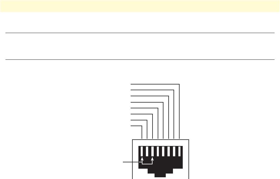
Introduction 105
Model 3202 Getting Started Guide C • Port pin-outs
Introduction
This section provides pin-out information for the ports of the Model 3202.
Console port
Configuration settings: 9600 bps, 8 bits, no parity, 1 stop bit, no flow control
Figure 54. EIA-561 (RJ-45 8-pin) port
Note N/C means no internal electrical connection.
12345678
8–RTS (N/C)
7–CTS (N/C)
6–TD
5–RD
4–SG
3–DTR
2–CD (N/C)
1–DSR
Pins 1 & 3 are
connected together
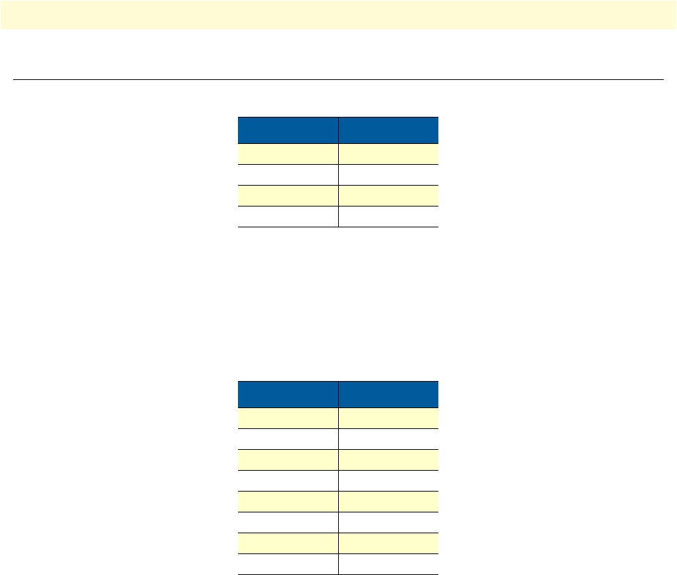
Ethernet 106
Model 3202 Getting Started Guide C • Port pin-outs
Ethernet
Note Pins not listed are not used.
Table 35. RJ45 socket 10/100Base-T
Pin Signal
1 TX+
2 TX-
3 RX+
6 RX-
Table 36. RJ45 socket 1000Base-T
Pin Signal
1 TRD0+
2 TRD0-
3 TRD1+
6 TRD1-
4 TRD2+
5 TRD2-
7 TRD3+
8 TRD3-
