Paxar 9474 Users Manual Corel Ventura 9474PMCV.CHP
9474 to the manual 04abc459-39eb-4a8b-856f-ca1a6baf534a
2015-02-06
: Paxar Paxar-9474-Users-Manual-517389 paxar-9474-users-manual-517389 paxar pdf
Open the PDF directly: View PDF ![]() .
.
Page Count: 96
Monarch
9474 Printer
TC9474PM 1/98 ©1998 Monarch Marking Systems, Inc. All rights reserved.

Each product and program carries a respective written warranty, the only
warranty on which the customer can rely. Monarch reserves the right to make
changes in the product, the programs, and their availability at any time and
without notice. Although Monarch has made every effort to provide complete
and accurate information in this manual, Monarch shall not be liable for any
omissions or inaccuracies. Any update will be incorporated in a later edition of
this manual.
©1997 Monarch Marking Systems, Inc. All rights reserved. No part of this
publication may be reproduced, transmitted, stored in a retrieval system, or
translated into any language in any form by any means, without the prior
written permission of Monarch Marking Systems, Inc.
WARNING
This equipment has been tested and found to comply with the limits for a Class A digital
device, pursuant to Part 15 of the FCC Rules. These limits are designed to provide
reasonable protection against harmful interference when the equipment is operated in a
commercial environment. This equipment generates, uses, and can radiate radio frequency
energy and, if not installed and used in accordance with the instruction manual, may cause
harmful interference to radio communications. Operation of this equipment in a residential
area is likely to cause harmful interference in which case the user will be required to correct
the interference at his own expense.
CANADIAN D.O.C. WARNING
This digital apparatus does not exceed the Class A limits for radio noise emissions from
digital apparatus set out in the Radio Interference Regulations of the Canadian Department
of Communications.
Le présent appareil numérique n’émet pas de bruits radioélectriques dépassant les limites
applicables aux appareils numériques de la classe A prescrites dans le Réglement sur le
brouillage radioélectrique édicte par le ministère des Communications du Canada.
Trademarks
MONARCH is a registered trademark of Monarch Marking Systems, Inc.
920, 924, 925 and 9474 are trademarks of Monarch Marking Systems, Inc.
Monarch Marking Systems
P.O. Box 608
Dayton, Ohio 45401

Table of Contents
INTRODUCTION. . . . . . . . . . . . . . . . . . . . . . . . . . . . . . . . . . . . . . . . . . . . . . . . . . . . . . . . 1-1
COMMUNICATION REQUIREMENTS. . . . . . . . . . . . . . . . . . . . . . . . . . . . . . . . . . . . . . . 2-1
Input Characteristics. . . . . . . . . . . . . . . . . . . . . . . . . . . . . . . . . . . . . . . . . . . . . . 2-2
Data Flow Control . . . . . . . . . . . . . . . . . . . . . . . . . . . . . . . . . . . . . . . . 2-2
Setting Communication Values. . . . . . . . . . . . . . . . . . . . . . . . . . . . . . . . . . . . . . 2-3
Cable Interface . . . . . . . . . . . . . . . . . . . . . . . . . . . . . . . . . . . . . . . . . . . . . . . . . . 2-5
MESSAGE STRUCTURES . . . . . . . . . . . . . . . . . . . . . . . . . . . . . . . . . . . . . . . . . . . . . . . 3-1
Creating Online Data Streams . . . . . . . . . . . . . . . . . . . . . . . . . . . . . . . . . . . . . . 3-2
Transmitting Online Data Streams . . . . . . . . . . . . . . . . . . . . . . . . . . . . . . . . . . . 3-2
Error Notification. . . . . . . . . . . . . . . . . . . . . . . . . . . . . . . . . . . . . . . . . . . . . . . . . 3-3
Data Transmission Errors. . . . . . . . . . . . . . . . . . . . . . . . . . . . . . . . . . . 3-3
Incorrect Data Errors . . . . . . . . . . . . . . . . . . . . . . . . . . . . . . . . . . . . . . 3-3
Monetary Symbols . . . . . . . . . . . . . . . . . . . . . . . . . . . . . . . . . . . . . . . . . . . . . . . 3-4
Commands . . . . . . . . . . . . . . . . . . . . . . . . . . . . . . . . . . . . . . . . . . . . . . . . . . . . . 3-4
Programming Conventions . . . . . . . . . . . . . . . . . . . . . . . . . . . . . . . . . 3-5
Standard Syntax Guidelines. . . . . . . . . . . . . . . . . . . . . . . . . . . . . . . . . . . . . . . . 3-5
Standard Syntax Guidelines for Batches . . . . . . . . . . . . . . . . . . . . . . . . . . . . . . 3-6
Format Data . . . . . . . . . . . . . . . . . . . . . . . . . . . . . . . . . . . . . . . . . . . . . . . . . . . . 3-7
Example . . . . . . . . . . . . . . . . . . . . . . . . . . . . . . . . . . . . . . . . . . . . . . . . 3-8
Format Header Record . . . . . . . . . . . . . . . . . . . . . . . . . . . . . . . . . . . . 3-8
Text Field Record . . . . . . . . . . . . . . . . . . . . . . . . . . . . . . . . . . . . . . . . . . . . . . . . 3-9
Bar Code Field Record. . . . . . . . . . . . . . . . . . . . . . . . . . . . . . . . . . . . . . . . . . . 3-12
Line Field . . . . . . . . . . . . . . . . . . . . . . . . . . . . . . . . . . . . . . . . . . . . . . . . . . . . . 3-16
Batch Data . . . . . . . . . . . . . . . . . . . . . . . . . . . . . . . . . . . . . . . . . . . . . . . . . . . . 3-19
Batch Header Record . . . . . . . . . . . . . . . . . . . . . . . . . . . . . . . . . . . . 3-19
Entering Print Data for Fields. . . . . . . . . . . . . . . . . . . . . . . . . . . . . . . 3-21
i

Using Multiple Batches with One Format . . . . . . . . . . . . . . . . . . . . . 3-23
Using Previously Defined Print Data. . . . . . . . . . . . . . . . . . . . . . . . . 3-23
Batch Separators. . . . . . . . . . . . . . . . . . . . . . . . . . . . . . . . . . . . . . . . 3-24
USING GRAPHICS . . . . . . . . . . . . . . . . . . . . . . . . . . . . . . . . . . . . . . . . . . . . . . . . . . . . . 4-1
Defining Graphic Image Data . . . . . . . . . . . . . . . . . . . . . . . . . . . . . . . . . . . . . . 4-2
Example . . . . . . . . . . . . . . . . . . . . . . . . . . . . . . . . . . . . . . . . . . . . . . . 4-5
Placing the Image in a Format. . . . . . . . . . . . . . . . . . . . . . . . . . . . . . . . . . . . . . 4-6
Clear Image Buffer. . . . . . . . . . . . . . . . . . . . . . . . . . . . . . . . . . . . . . . . . . . . . . . 4-8
Field. . . . . . . . . . . . . . . . . . . . . . . . . . . . . . . . . . . . . . . . . . . . . . . . . . . 4-8
Compressing the Data Stream . . . . . . . . . . . . . . . . . . . . . . . . . . . . . . 4-8
QUICK REFERENCES . . . . . . . . . . . . . . . . . . . . . . . . . . . . . . . . . . . . . . . . . . . . . . . . . . 5-1
Text Font Sizes . . . . . . . . . . . . . . . . . . . . . . . . . . . . . . . . . . . . . . . . . . . . . . . . . . 5-1
Fonts . . . . . . . . . . . . . . . . . . . . . . . . . . . . . . . . . . . . . . . . . . . . . . . . . . 5-1
Parallel Characters . . . . . . . . . . . . . . . . . . . . . . . . . . . . . . . . . . . . . . . 5-2
Rotated Characters . . . . . . . . . . . . . . . . . . . . . . . . . . . . . . . . . . . . . . . 5-2
Character Width (in Dots) . . . . . . . . . . . . . . . . . . . . . . . . . . . . . . . . . . . . . . . . . 5-2
Parallel Character Width (in Dots). . . . . . . . . . . . . . . . . . . . . . . . . . . . 5-3
Bar Codes . . . . . . . . . . . . . . . . . . . . . . . . . . . . . . . . . . . . . . . . . . . . . . 5-3
Bar Code Densities . . . . . . . . . . . . . . . . . . . . . . . . . . . . . . . . . . . . . . . 5-4
Bar Code Densities . . . . . . . . . . . . . . . . . . . . . . . . . . . . . . . . . . . . . . . 5-4
Line Width . . . . . . . . . . . . . . . . . . . . . . . . . . . . . . . . . . . . . . . . . . . . . . . . . . . . . 5-5
Special Characters. . . . . . . . . . . . . . . . . . . . . . . . . . . . . . . . . . . . . . . . . . . . . . . 5-6
Code 128 Function Codes . . . . . . . . . . . . . . . . . . . . . . . . . . . . . . . . . . . . . . . . . 5-6
ASCII Characters. . . . . . . . . . . . . . . . . . . . . . . . . . . . . . . . . . . . . . . . . . . . . . . . 5-7
Printable Characters by Font . . . . . . . . . . . . . . . . . . . . . . . . . . . . . . . 5-8
English/Metric Conversion. . . . . . . . . . . . . . . . . . . . . . . . . . . . . . . . . . . . . . . . . 5-9
ERROR MESSAGES . . . . . . . . . . . . . . . . . . . . . . . . . . . . . . . . . . . . . . . . . . . . . . . . . . . . 6-1
Diagnostic Messages. . . . . . . . . . . . . . . . . . . . . . . . . . . . . . . . . . . . . . . . . . . . . 6-2
Startup Messages . . . . . . . . . . . . . . . . . . . . . . . . . . . . . . . . . . . . . . . . . . . . . . . 6-2
Operation Messages . . . . . . . . . . . . . . . . . . . . . . . . . . . . . . . . . . . . . . . . . . . . . 6-4
ii

Printer Errors . . . . . . . . . . . . . . . . . . . . . . . . . . . . . . . . . . . . . . . . . . . . . . . . . . . 6-5
General Warnings . . . . . . . . . . . . . . . . . . . . . . . . . . . . . . . . . . . . . . . . 6-5
General Errors . . . . . . . . . . . . . . . . . . . . . . . . . . . . . . . . . . . . . . . . . . . 6-5
Communication Errors . . . . . . . . . . . . . . . . . . . . . . . . . . . . . . . . . . . . . 6-8
Offline Messages . . . . . . . . . . . . . . . . . . . . . . . . . . . . . . . . . . . . . . . . . . . . . . . . 6-9
Data Entry or Test Print Errors . . . . . . . . . . . . . . . . . . . . . . . . . . . . . . . 6-9
Format Entry Errors . . . . . . . . . . . . . . . . . . . . . . . . . . . . . . . . . . . . . . . . . . . . . 6-11
Online Messages . . . . . . . . . . . . . . . . . . . . . . . . . . . . . . . . . . . . . . . . . . . . . . . 6-13
Online Warnings. . . . . . . . . . . . . . . . . . . . . . . . . . . . . . . . . . . . . . . . . 6-13
Online Communication Errors . . . . . . . . . . . . . . . . . . . . . . . . . . . . . . 6-16
SAMPLE DATA STREAMS . . . . . . . . . . . . . . . . . . . . . . . . . . . . . . . . . . . . . . . . . . . . . . . . A-1
Formats, Text and Bar Code Fields . . . . . . . . . . . . . . . . . . . . . . . . . . . . . . . . . . A-2
Sample Format Data Stream . . . . . . . . . . . . . . . . . . . . . . . . . . . . . . . . A-2
Sample Batch Data Stream . . . . . . . . . . . . . . . . . . . . . . . . . . . . . . . . . A-2
Line Fields . . . . . . . . . . . . . . . . . . . . . . . . . . . . . . . . . . . . . . . . . . . . . . . . . . . . . A-3
Sample Format Data Stream . . . . . . . . . . . . . . . . . . . . . . . . . . . . . . . . A-3
Sample Batch Data Stream . . . . . . . . . . . . . . . . . . . . . . . . . . . . . . . . . A-3
Graphic Images . . . . . . . . . . . . . . . . . . . . . . . . . . . . . . . . . . . . . . . . . . . . . . . . . A-4
Sample Format Data Stream . . . . . . . . . . . . . . . . . . . . . . . . . . . . . . . . A-5
Sample Batch Data Stream . . . . . . . . . . . . . . . . . . . . . . . . . . . . . . . . . A-5
Compressed Graphic Data. . . . . . . . . . . . . . . . . . . . . . . . . . . . . . . . . . . . . . . . . A-6
Sample Compressed Graphic Data Stream . . . . . . . . . . . . . . . . . . . . A-6
Sample Format Data Stream . . . . . . . . . . . . . . . . . . . . . . . . . . . . . . . . A-6
Sample Batch Data Stream . . . . . . . . . . . . . . . . . . . . . . . . . . . . . . . . . A-6
CODE 128 INFORMATION. . . . . . . . . . . . . . . . . . . . . . . . . . . . . . . . . . . . . . . . . . . . . . . . B-1
Bar Code Width . . . . . . . . . . . . . . . . . . . . . . . . . . . . . . . . . . . . . . . . . . . . . . . . . B-2
Quiet Zone . . . . . . . . . . . . . . . . . . . . . . . . . . . . . . . . . . . . . . . . . . . . . . . . . . . . . B-4
Function Codes. . . . . . . . . . . . . . . . . . . . . . . . . . . . . . . . . . . . . . . . . . . . . . . . . . B-5
128 Bar Code Character Sets . . . . . . . . . . . . . . . . . . . . . . . . . . . . . . . . . . . . . . B-6
iii

iv

INTRODUCTION 1
This manual tells you how to enter online formats and batch data
for downloading to a Monarch® 9474 printer.
Refer to your Operator’s Handbook for general setup and
maintenance procedures, an explanation of data entry and batch
control for offline printing, and about creating and entering offline
formats.
Introduction 1-1

The 9474 printer can receive print data online from a host.
During online communication, the host treats the printer as an
RS-232 type printer. For the printer to communicate online, you
will need an RS-232 cable. For mainframe communication, you
may need a protocol converter.
Transmitting data from the host requires communication controls.
See Chapter 2, "Communication Requirements" for more
information.
Three types of data can be transmitted:
Format data The user-designed layout for online formats.
These formats are used by online batches for
printing.
These online formats can also be used
offline. However, formats created offline
cannot be used online.
Batch data Contains the format number and actual data
to be printed on the supply. Batch data is
downloaded to the printer and combined with
a format stored in the printer.
Graphic data Contains the actual pixel data which forms a
graphic image.
Format, batch, and graphic data are stored
when you turn the power off.
Format and graphic data may be sent at any time.
Since batch data is combined with a format for printing, the format
and graphic data for a batch must reside in the printer before
sending the batch.
Each data type has its own data stream structure. See Chapter 3,
"Message Structures" for more information.
1-2 Introduction

COMMUNICATION
REQUIREMENTS
2
To enable communications between the printer and the computer,
the printer communications setup must match the setup for the
host. The options are:
NBaud rate
NParity
NData flow control
NData bits
NStop bits
All online data uses the ASCII (American Standard Code for
Information Interchange) character code for interpretation of bits
as characters.
Communication Requirements 2-1

Input Characteristics
Below are the input characteristics for communications. The
defaults are shown in bold print.
NAsynchronous
NFull duplex
NSelectable options:
Baud rate 110, 300, 600, 1200, 2400, 4800, 9600
Parity No parity, Odd, Even
Data flow Xon/Xoff, Data Terminal Ready (DTR)
Data bits Seven (7) or eight (8)
Stop bits One (1) or two (2)
Modify these communication settings on your printer as necessary
to match the settings on your host. See "Setting Communication
Values" for more information.
There are three main buffers: batch, format, and graphic. The
printer also has a 1024 byte input buffer which holds data until it
is processed into the respective buffer(s).
Data Flow Control
The printer uses Xon/Xoff or data terminal ready (DTR) for data
flow control. DTR flow control is usually required if you are using
an IBM-PC, unless the PC has a special Xon-Xoff program.
In DTR mode, the printer activates DTR when the printer can
accept more data from the host and deactivates when the
printer’s receive buffer is nearly full. In Xon/Xoff Mode, the
printer sends the Xon character when the printer can accept more
data and sends Xoff when the printer buffer is nearly full.
In either mode, once the printer has indicated that its buffer is
nearly full (by sending Xoff or deactivating DTR), up to 134
additional characters may be accepted without losing any data.
2-2 Communication Requirements

The printer does not require any hardware or software signals
from the host system in order to operate.
Flow control characters can be changed
offline through the Printer Configuration mode.
The total number of formats, batches, and graphics is only limited
by the amount of memory available.
Setting Communication Values
To set the communication parameters, follow the instructions
below. For more information on operating the printer, refer to the
Operator’s Handbook.
1. From the main menu, press d to display Printer
Configuration. Press e . You’ll see
Enter password: _ _ _ _ _ _ _ _
Enter the 1-8 character password and press e .
When you first receive the printer, the
password is MANAGER or ONLINE.
2. You’ll see the Configuration Options menu.
Select Config Option:
Define Check Digit Schemes
Press d until you see Host Port Configuration. Press e
to select this option. With each parameter, you can enter a
new selection, or just press e to keep the value that is
displayed.
Communication Requirements 2-3
3. You’ll see the Host Option menu and the first online
parameter.
Select Baud Rate:
2400
Press d or u until you see the baud rate you need, then
press e . You’ll see
Enter Parity: N
N)one, O)dd or E)ven
4. Select the parity you need and press e . You’ll see
Enter Word Length [7-8]: 8
5. Select the word length you need and press e . You’ll see
Enter Stop Bits [1-2]: 1
6. Select the stop bits you need and press e . You’ll see
Enter Start (XON) character:
17
7. Enter a number from 1-127 for XON flow control, or 128 for
DTR flow control. You’ll see
Enter Stop (XOFF) character:
19
8. Enter a number from 1-127 for XOFF flow control, or 128 for
DTR flow control.
2-4 Communication Requirements

If you select DTR control (128) as the XON character, the
printer automatically sets 128 (DTR control) for the XOFF
character.
The Start and Stop characters must be set at 128 (DTR flow
control) for IBM PC equipment.
You’ll see the Configuration Options menu. Press 1 to exit
to the main menu.
Cable Interface
The printer accepts standard RS-232C electrical signal
transmissions when it is connected to a DB-25S connector
configured as Data Terminal Equipment (DTE). For correct
operation, use all defined pins.
For PC null modems, plug the RS-232 cable into:
NA serial (RS-232) port on the host or protocol converter
NThe 25-pin RS-232 connector on your printer. Refer to your
Operator’s Handbook for more information.
The RS-232C cable interface is set up as a terminal device (DTE):
Pin Description
3 Received Data
5 Clear to Send Input
6 Data Set Ready
2 Transmitted data
4 Request to send Output
20 Data Terminal Ready
1 Protective ground Ground
7 Signal ground
All other pins are open.
Communication Requirements 2-5
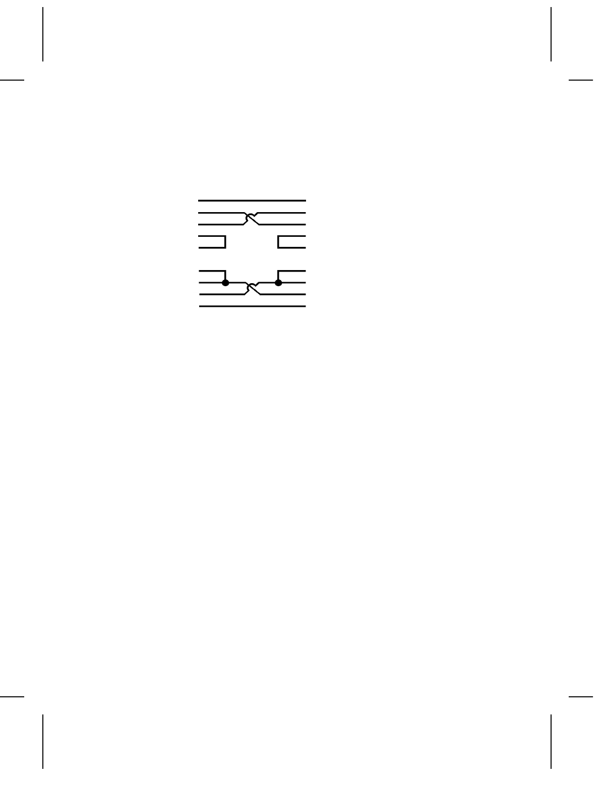
The cable interface for PC null modems is shown below.
9474 PC
FG 1 1 FG
TD 2 2 TD
RD 3 3 RD
RTS 4 4 RTS
CTS 5 5 CTS
DSR 6 6 DSR
CD 8 8 CD
DTR 20 20 DTR
SG 7 7 SG
2-6 Communication Requirements

MESSAGE STRUCTURES 3
This chapter has information and message structures for
NFormats
NBatch Data
Graphic image data is discussed in Chapter 4, "Using Graphics."
Message Structures 3-1

Creating Online Data Streams
Create data streams for your 9474 printer using a standard text
editor, such as EDLIN or TSO.
If you use a word processor to create data streams, make sure to
save the file in text-only or unformatted mode.
Transmitting Online Data Streams
Your printer must be in Online Mode before it will accept data
from your computer.
NSelect Online from the Select Operating Mode menu.
NPress e . You’ll see
Online Mode Ready:
Your printer is now ready to accept data.
Send data to the printer just as you would send any print data to a
printer from your computer.
For example, if you have a file named FORMAT1.DAT on an
MS-DOS system, you could send the data to your printer with
these commands:
MODE COM1:2400,N,8,1,P
MODE LPT1:=COM1
PRINT FORMAT1.DAT
This set of commands would send the file FORMAT1.DAT to a
printer connected to COM1 of an MS-DOS computer.
Format and graphic structures can be sent at any time.
Formats or graphics used by batch data must be sent before the
batch data referencing them. Any batch sent without a previously
defined format is ignored, generating an error.
3-2 Message Structures

Error Notification
Data handling and error checking are resident in the printer. If an
error in transmission occurs, an error is displayed on the printer
keypad display. However, no message is sent to the host and
processing continues until the end of the transmission.
Certain errors may put the printer in offline mode. See Chapter 6,
"Error Messages," for a list of possible messages.
Data Transmission Errors
The printer displays errors that occur during data
transmission. Printer fault errors stop the machine, which will
not resume printing until the operator corrects the error
condition. All these messages take the system offline.
Incorrect Data Errors
The printer pauses when it receives incorrect data from the
host. During the pause, it displays a message and beeps.
After ten seconds, or when the operator presses e, the
printer resumes operation. Normally, the printer loses the
data that caused the error.
If the host or the communications line goes down during
transmission, the printer displays the message
Waiting for command terminator.
Press F1 to abort download.
If you press 1 , the batch or format data that was being sent will
be lost and must be retransmitted.
Message Structures 3-3
Monetary Symbols
The default monetary symbols are the U.S. dollar and cents. The
ASCII characters $ (24 hex) and ^ (5E hex) represent the dollar
and cent symbols.
If you change your printer settings to use international pricing
symbols, these characters will then represent the new symbols.
For monetary selections that don’t have a cent equivalent, the ^
character is changed to a space.
In EBCDIC-based systems a ^ is not
available. Use ~94 to print a cent sign.
Commands
The following command characters are used in 9474 online data
streams.
Command
Character Hex
Value Description
{ 7B Open brace. Command LEADIN character
, 2C Comma. Inter-field separator (IFS)
; 3B Semicolon. Beginning of string character
p 7C Split vertical bar. Command inter-record
separator (IRS)
} 7D Close brace. Command TERMINATOR
character
3-4 Message Structures

Programming Conventions
All online commands from the host follow these rules.
NAll data after the TERMINATOR character ( } ) and before the
next LEADIN character ( { ) is ignored.
NThe hex values 7B, 7C and 7D are reserved as command
delimiters. All data of a value less than 20 hex and greater
than 7E hex is ignored.
NAll data strings (batch data, compressed bit-map images or
format data) begin with a semi-colon (3BH) and end with a
TERMINATOR or inter-record separator (IRS or p (7C hex)).
NAll space characters, except string definitions, are ignored.
NAll strings must be less than 100 characters.
Standard Syntax Guidelines
NA format header must be the first record in your format.
NBegin the format name with the beginning of string
character (;).
NBegin a record with a LEADIN character ({).
NMake sure the length and width in these records match your
supply length and width. Remember, these numbers are in
tenths of millimeters, so 500 equals 50 millimeters or 5
centimeters.
NMake sure the row and column locations in the text, bar code,
or line records are less than the supply length and width.
NAllow enough space to hold all the characters in the field, the
bar code height, or the line end point without running off the
supply.
NField definitions may be sent in any order, regardless of field
location. The last field carries priority over previous fields and
overwrites the previous fields if they overlap when printed.
Message Structures 3-5

NTo print human readable characters for Code 39, Interleaved 2
of 5, Codabar, Code 128 and MSI bar codes, create a
separate text field. However, using this method with UPC or
EAN bar codes may not correctly print the bar code.
NA new format with the same ID number as a previously defined
format overwrites the old format. However, the old format is
not overwritten until all batches queued to use the old format
are completed.
NEnd records with a record separator ( p ).
NEnd the last record in your format with a terminator
character (}).
Standard Syntax Guidelines for Batches
Read the standard syntax guidelines and note the additional items
for batches.
NA batch header must be the first record in your batch.
NFor a batch header record or batch data, make sure the
number in the first parameter matches the number of the
format you are using.
NIf you choose auto-naming (the printer assigns a batch name),
make sure there are no characters or spaces between the
beginning of string character (;) and the record separator ( p ).
NIf the field is an incrementing field, you can enter any type of
characters; however, only the numeric data increments.
NSend the correct format to the printer before sending the
batch. Batch data without a defined format generates an error.
3-6 Message Structures

Format Data
Format data contains the following:
NFormat identification number and name
NSupply size
NOnline field definitions for text, bar code, line and graphic fields
The following offline format elements are not supported online:
NMerged fields
NSub-fields
NTime or date fields
NUser-defined check digits
NFixed characters
NAlphanumeric distinction
NFixed or variable length
NPrice fields
You must supply these elements if you need them in your program.
The message structure used to transmit online format data is
shown below, followed by an example.
{FORMAT ID, LENGTH, WIDTH; FORMAT_NAME p
TEXT FIELD, INCREMENT FLAG, INCREMENT VALUE, ROW,
COLUMN, MULTIPLE, TEXT FONT,
CHARACTER ROTATION, FIELD ROTATION, COLOR p
BARCODE FIELD, INCREMENT FLAG, INCREMENT VALUE,
ROW, COLUMN, DENSITY,BAR CODE FONT,
FIELD ROTATION, HEIGHT, READABLE CHARACTERS p
LINE FIELD, ROW, COLUMN, DIRECTION, STOP,
THICKNESS p
GRAPHIC FIELD, ROW, COLUMN p
.
.}
Message Structures 3-7

Example
This example has three text fields and one bar code field.
{F1,0558,0507;ONLINE p
T00,I,000,0475,0050,1,1,0,0,B p
T01,I,000,0406,0050,1,1,0,0,B p
T02,I,000,0017,0253,1,1,0,0,B p
B00,I,000,0124,0093,1,1,0,0177,1 p }
The format header record (beginning with the Format ID) must
always be the first record in a format data stream.
Spaces can be used in the data stream.
However, if used in a string following a
semi-colon, they will be treated as printable
characters.
Format Header Record
The format header record is constructed as shown below.
Syntax {F##,LENGTH,WIDTH;FORMAT NAME p
Field Contents
F## Must begin with the letter ’F’ to represent the beginning of a
format data stream.
The F is followed by a one or two digit number as the format ID
Values: 0-99
Example: F23 = Format number 23
LENGTH One to four digits to define the supply length in tenths of
millimeters.
Values: 191-2032 (19.1 to 203.2 mm
or 0.75 to 8.0 inches)
Examples: 200 = 20mm
201 = 20.1mm
WIDTH
3-8 Message Structures

One to four digits to define the width of the supply in tenths of
millimeters (across the printhead).
Values: 191-1078 (0.75 to 4.25 inches)
;FORMAT_NAME One to eight-character name assigned by the user. It can
contain any ASCII alphanumeric character, including slash (/),
hyphen (-), space ( ), dollar sign ($), or decimal point (.).
The Format Name is a character string, so it is preceded by a
semicolon (;).
Example {F23, 500, 200;TEXTILES p
The format number is F23, the supply length is 50 millimeters, the
supply width is 20 millimeters, and the format is named
"TEXTILES."
Text Field Record
The text field record is constructed as shown below:
Syntax T##,IFLAG,IVALUE,ROW,COL,MAG,TFONT,C-ROT,
F-ROT,COLOR p
Field Contents
T## Must begin with the letter ‘T’ for a text field.
The T is followed by one or two digits for the field number.
There can be up to 100 fields per format, in any combination
of text, barcode, line, or graphic fields.
Values: 0-99
IFLAG You can set numeric fields to increase or decrease in value as
each ticket is printed.
This parameter consists of one character to define the field as
incremented, decremented, or constant.
Values: I = Increment
D = Decrement
Message Structures 3-9

If the field does not change, define IFLAG as ‘I’ and set
IVALUE to zero (0).
NOTE: Do not select incrementing on fields that contain a
check digit.
IVALUE One to three digits to define the amount by which the value in
the field increases or decreases as each ticket is printed. If
the field does not change, define IFLAG as ‘I’ and set IVALUE
to zero (0).
Values: 0-999
NOTE: The first number in the count sequence must contain
the same number of digits as the highest number to
be counted. For example, to count the numbers 1 to
999, the first number in the sequence must be entered
as 001.
ROW One to four digits to define the row location of the field on the
supply. This is the distance from the the guide edge zero
point at the bottom of the supply and the bottom of the field.
The zero point is 1.5 mm or 0.060 inches from the bottom of
the supply. The bottom of the supply is the edge that exits the
printer first.
This value is measured in tenths of millimeters (TOMMS) and
must be less than the maximum length of the supply.
Values: 0-2032
COL One to four digits to define the column location of the field on
the supply. This is the distance from the guide edge zero
point at the left edge of the supply and the left edge of the
field.
The zero point is 1.5 mm or 0.060 inches from the left edge of
the supply.
The unit of measurement is tenths of millimeters. The range
must be less than the maximum width of the supply.
Values: 0-1016 (0 to 4 inches)
MAG One to two digits as the magnification factor for the font of
text fields.
Values: 1 - 10
3-10 Message Structures

Font magnifications creating greater than 30% black print on a
format may result in lower print quality.
TFONT One digit as the font for the TEXT field. See Chapter 5,
"Quick References," for font samples.
Values: 1Standard
2Reduced
3Bold
5OCR-A
6UPC HR1
7UPC HR2
C-ROT Character rotation. The direction characters point with
respect to the field.
Values: 0 = tops of characters toward top of field
1 = tops of characters toward left of field
F-ROT Field rotation. The direction of the field with respect to the
supply.
Values: 0 = top of field toward top of supply
1 = top of field toward left of supply
2 = top of field toward bottom of supply
3 = top of field toward right of supply
COLOR One character to define the color of a text field.
Values: B = Black characters (42H)
W = White characters on black (57H)
Example T05,I,0,230,30,1,1,0,0,B p
The text field number is T05, the field does not change value with
successive tickets (IFLAG = I, increment value = 0). The field
begins 23 millimeters from the bottom and 3 millimeters from the
left edge of the print area. The font appears at normal size
(magnification = 1) and the Standard font is used (1). The tops of
characters point to the top of the field (character rotation = 0) and
the top of the field points to the top of the supply (rotation = 0).
Characters appear in Black.
Message Structures 3-11

Bar Code Field Record
The bar code field record is constructed as shown below.
Syntax B##,IFLAG,IVALUE,ROW,COL,DENSITY,BFONT,
F-ROT,HEIGHT,HR p
Field Contents
BARCODE Must be the letter ‘B’ for a bar code field.
The B is followed by one or two digits for the field number.
There can be up to 100 fields per format, in any combination
of text, barcode, line, or graphic fields.
Values: 0-99
IFLAG You can set numeric fields to increase or decrease in value as
each ticket is printed.
This parameter consists of one character to define the field as
incremented, decremented, or constant.
Values: I = Increment
D = Decrement
If the field does not change, define IFLAG as ‘I’ and set
IVALUE to zero (0).
NOTE: Do not select incrementing on UPC or EAN bar codes
or fields that contain a check digit.
IVALUE One to three digits to define the amount by which the value in
the field increases or decreases as each ticket is printed. If
the field does not change, define IFLAG as ‘I’ and set IVALUE
to zero (0).
NOTE: The first number in the count sequence must contain
the same number of digits as the highest number to
be counted. For example, to count the numbers 1 to
999, the first number in the sequence must be entered
as 001.
Values: 0-999
ROW One to four digits to define the row location of the field on the
supply. This is the distance from the guide edge zero point at
the bottom of the supply and the bottom of the field.
3-12 Message Structures

The zero point is 1.5 mm or 0.060 inches from the bottom of
the supply. The bottom of the supply is the edge that exits the
printer first.
This value is measured in tenths of millimeters (TOMMS) and
must be less than the maximum length of the supply.
Values: 0-2032
NOTE: The minimum row location for serial bar code fields is
23 (0.09 inches)
COL One to four digits to define the column location of the field on
the supply. This is the distance from the guide edge zero
point at the left edge of the supply and the left edge of the
field.
The zero point is 1.5 mm or 0.060 inches from the left edge of
the supply.
The unit of measurement is tenths of millimeters. The range
must be less than the maximum width of the supply.
Values: 0-1016 (0 to 4 inches)
DENSITY One digit for the bar code density for Interleaved 2 of 5, Code
128, MSI, Code 39, and UPC/EAN bar codes.
Values: 1-5
Some bar codes do not support all 5 values.
For the actual densities for these values, see Chapter 5,
"Quick References."
BFONT One digit indicating which bar code font to use.
Values: 1UPC-A
2UPC-E
3Interleaved 2 of 5
4Code 39
5Codabar
6EAN-8
7EAN-13
8Code 128
9MSI
10 UPC/EAN+2
11 UPC/EAN+5
Message Structures 3-13

F-ROT Field rotation. The direction of the field with respect to the
supply.
Values: 0 = top of field toward top of supply
1 = top of field toward left of supply
2 = top of field toward bottom of supply
3 = top of field toward right of supply
HEIGHT One to four digits for the bar code height in tenths of
millimeters. The value should be less than the length or width
of the supply.
Values: 50-2032 (5.1 to 203.2 mm or 0.2 to 8.0 inches)
HR (Human readable characters) One digit for the location of
human readable characters printed with a UPC or EAN bar
code. If no value is given, no human readable characters are
printed.
Values: 0 = No human readable characters printed
1 = Human readable printed above the bar code
2 = Human readable printed below the bar code
NOTE: Always use the HR parameter to generate the human
readable text for a UPC or EAN bar code. If you
manually insert human readable text, the barcode
may not print accurately.
Example B11,I,1,70,30,1,4,0,120,0 p
The bar code field number is B11, the field increases by 1 with
successive tickets (IFLAG = I, increment value = 1). The field
begins 7 millimeters from the bottom and 3 millimeters from the
left edge of the print area. The bar code density is 6.63
characters per inch (density = 1, code 39), and Code 39 (4) is
used. The top of the field points to the top of the supply (rotation
= 0). The height of the bar code is 12 millimeters and no human
readable characters appear with this bar code (0).
The following special restrictions apply to online bar codes:
UPCA You must send a leading zero, 11 digits of
data and a check digit (13 digits total).
3-14 Message Structures

UPCE The printer automatically prints a leading zero
for this bar code. You must send data and a
check digit (7 digits total).
EAN13 You must send 12 digits of data and a check
digit (13 digits total).
EAN8 You must send 7 digits of data and a check
digit (8 digits total).
NOTE: If the check digit is incorrect or omitted from a
UPC or EAN bar code, the printer will
automatically place the correct check digit in
the bar code.
I 2 of 5 This bar code has no check digit. The printer
automatically prints the start and stop
characters, so only the data must be sent.
The length of the data is variable. If the data
has an odd number of digits, add a leading
zero to make the length even.
Code 39 The start and stop characters must be placed
at the beginning and end of the data before it
is sent to the printer. The start and stop
character is an asterisk (*). The length of the
data is variable.
Codabar The start and stop characters must be placed
at the beginning and end of the data before it
is sent to the printer. The start and stop
characters are a combination of lowercase a,
b, c, or d. The length of this data is variable.
Code 128 You can send characters for Function Codes
1-4 as fixed data when defining a code 128
field and as batch data when printing.
To send the Function Codes, use a tilde (~)
followed by a three digit ASCII code as shown
in the following table.
Message Structures 3-15
For example, to print a string of bar code data
with function code F2 as the fourth character...
123(F2)5678
send this string of characters...
123~1295678
ASCII Code Function Code
~134 F1
~129 F2
~128 F3
~132 F4
Two additional bar codes are supported as extensions to both
UPC and EAN bar codes.
+2 Send exactly two digits for this bar code.
+5 Send exactly six digits (a five-digit bar code and a
one-digit check digit).
Line Field
The message structure below transmits a line field. This data
stream defines the bit map to form a graphic line field. Use the
line field to emphasize data by printing a line or box.
You can have up to 100 line images. The line record can be
placed in a format data stream anywhere following the format
header record. Lines are counted as fields, just like text or bar
code fields. When determining the number of fields in your
format, count each line as a separate field.
Syntax L##, ROW, COLUMN, DIRECTION, STOP,
THICKNESS p
3-16 Message Structures

Field Contents
L## Must begin with the letter ’L’ for a line field.
The L is followed by one or two digits for the field number.
There can be up to 100 fields per format, in any combination
of text, barcode, line, or graphic fields.
Values: 0-99
ROW One to four digits to define the row location of the field on the
supply. This is the distance from the the guide edge zero
point at the bottom of the supply and the bottom of the field.
The zero point is 1.5 mm or 0.060 inches from the bottom of
the supply. The bottom of the supply is the edge that exits the
printer first.
This value is measured in tenths of millimeters (TOMMS) and
must be less than the maximum length of the supply.
Values: 0-2032
COLUMN One to four digits to define the column location of the field on
the supply. This is the distance from the guide edge zero
point at the left edge of the supply and the left edge of the
field.
The zero point is 1.5 mm or 0.060 inches from the left edge of
the supply.
The unit of measurement is tenths of millimeters. The range
must be less than the maximum width of the supply.
Values: 0-1016 (0 to 4 inches)
DIRECTION One digit to define the direction of the line.
Values: 0 = Vertical
1 = Horizontal
STOP One to four digits to define the stop position (Row or Column,
dependent on the DIRECTION setting) for the line.
Values: 1-2032
THICKNESS One or two digits for the line thickness in dots. 1 dot = 1/192
inch
Values: 1-15
Message Structures 3-17
Example L22,400,100,1,190,5 p
The line field number is L22, the line begins 40 millimeters from
the bottom and 10 millimeters from the left edge of the print area.
The line is horizontal (direction = 1) and ends 19 millimeters from
the left edge of the supply. The line is 5 dots thick.
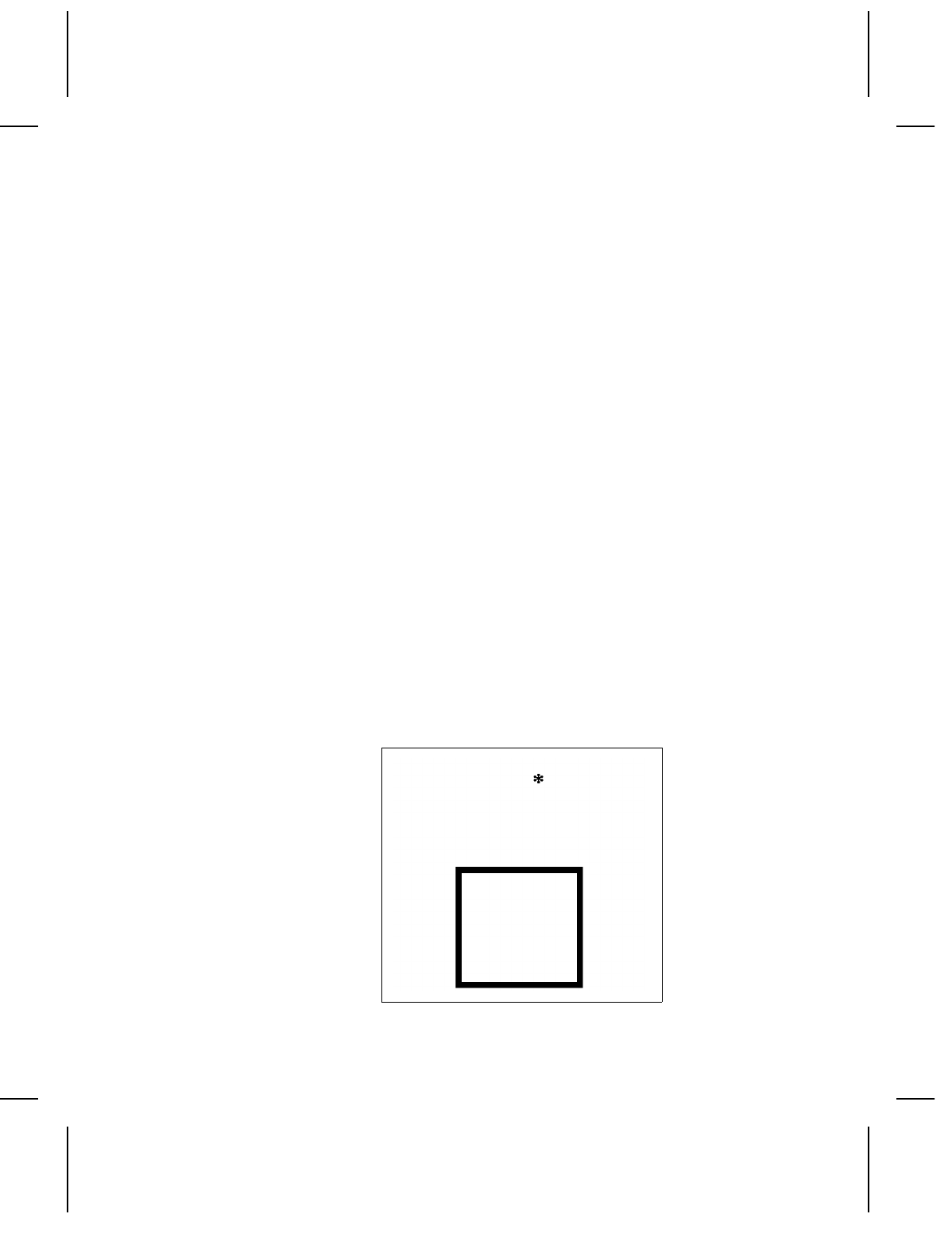
Example
This example draws a simple 1-inch box starting at row 50 and
column 50 on a 2" x 2.5" tag, as shown below.
Format
{F1,635,508;BOX p
L0,50,50,0,304,3 p
L1,50,50,1,304,3 p
L2,50,304,0,304,3 p
L3,304,50,1,316,3 p }
Batch
{B1,1,0,1,1,1,C;BOX.TEST p }
Note that line L3 is longer than the other 3 lines to complete the
box in the upper right corner.
3-18 Message Structures

Batch Data
The batch data stream contains:
NBatch information:
- format number (layout for the print image)
- print quantity
- supply definition
- item description (batch name)
NPrint image:
- field numbers
- data to be printed in each field
The message structure used to provide the printed data for an
online format is shown below. An example follows.
{B##,QUANTITY,CUT,REP,PARTS,0,MODE;BATCH_NAME p
T##;(..print data..) p
B##;(..print data..) p
.
.
.}
Batch Header Record
The batch header is the first record in the batch data stream.
Syntax {B##,QUANTITY,CUT,REP,PARTS,0,MODE;
BATCH_NAME p
Field Contents
B## Must begin with the letter ’B’ to begin a batch data stream.
The B is followed by the one or two digit number that matches
the format number. This is the number at the beginning of the
format record.
Values: 0-99
QUANTITY One to four digits for the quantity to print in a given batch.
Values: 1-9999
CUT/TAKEUP On printers with a knife:
Message Structures 3-19

One digit to control how tickets are cut.
Values: 0 = no cut
1 = cut each ticket in the batch (except last ticket)
2 = cut each ticket in the batch (including
last ticket in batch)
3 = cut between batches
NOTE: Do not use option 2 if your supply is less than 4
inches long (1016 tomms) or more than 8 inches long
(2032 tomms)
When using option 2, the first 0.7 inches of the supply cannot
be used for printing.
On non-knife printers:
On a 9474 with no knife, this parameter controls the backing
paper takeup, instead of the knife.
Values: 0 = print tags with no backing paper.
1 = print labels and take up the backing paper.
REP One to four digits for the supply repetition for cutting, and
increment/decrement field.
Values: 1-9999
PARTS One digit for the number of parts across the supply.
Values: 1-5
RESERVED Enter 0.
MODE One character to define the mode of printing, or batch
separator.
Values: 0 = separator off.
1 = double length separator (use for 924 or 925
stacker). 3 mm extra length tag on 920 stacker.
2 = normal length separator with 3 mm black stripe.
3 = 3 mm extra length tag with 6 mm stripe.
NOTE: If using value 0,1, 2, or 3, do not use a separate
batch separator packet.
3-20 Message Structures

C = Continuous
D = On Demand
If you enter D (On Demand) in the MODE field on a printer
with a knife, the value will default to C (Continuous).
;BATCH_NAME One to eight characters for the name of the batch. A priority
batch name must begin with a decimal. For example:
.SOCKS12.
Each batch should have a unique name, or you can omit the
name for automatic batch naming. If multiple batches are
sent with the same name, all batches are stored with the
same name. If you omit the batch name, the printer will
generate unique names which begin with the letters "AUTO"
and end with a 4-digit number. The 4-digit number is an
increment and can have a value from 1-9999 (example:
AUTO1354, where 1354 equals the increment).
Example {B11,200,2,5,2,0,3; p
The batch prints data using format 11 and prints 200 tickets. The
printer cuts after each ticket is printed, including the last ticket (2)
and each ticket will print 5 times. This is a two-part ticket. The
format prints 2 times horizontally across each ticket. A
double-length separator prints between batches (3). The batch
name is automatically assigned by the printer, because there are
no characters between the semi-colon and the record separator.
Entering Print Data for Fields
Enter the data to print in each field after the batch header record
as shown.
Syntax {B##,QUANTITY,CUT,REP,PARTS,0,MODE;
BATCH_NAME p
T##;print data.. p
B##;print data.. p
.
.
.}
Message Structures 3-21
T## The number of the text field to print (enter the number in place
of ##).
B## The number of the bar code field to print (enter the field
number in place of ##).
;print data p Enter the data you want to print in this field.
This character string begins with a semi-colon (;) and can be
1 to 100 characters long. Place a record separator ( p ) at the
end of this string.
If there is a text field you don’t want to use, enter that field
number and a semi-colon with no print data.
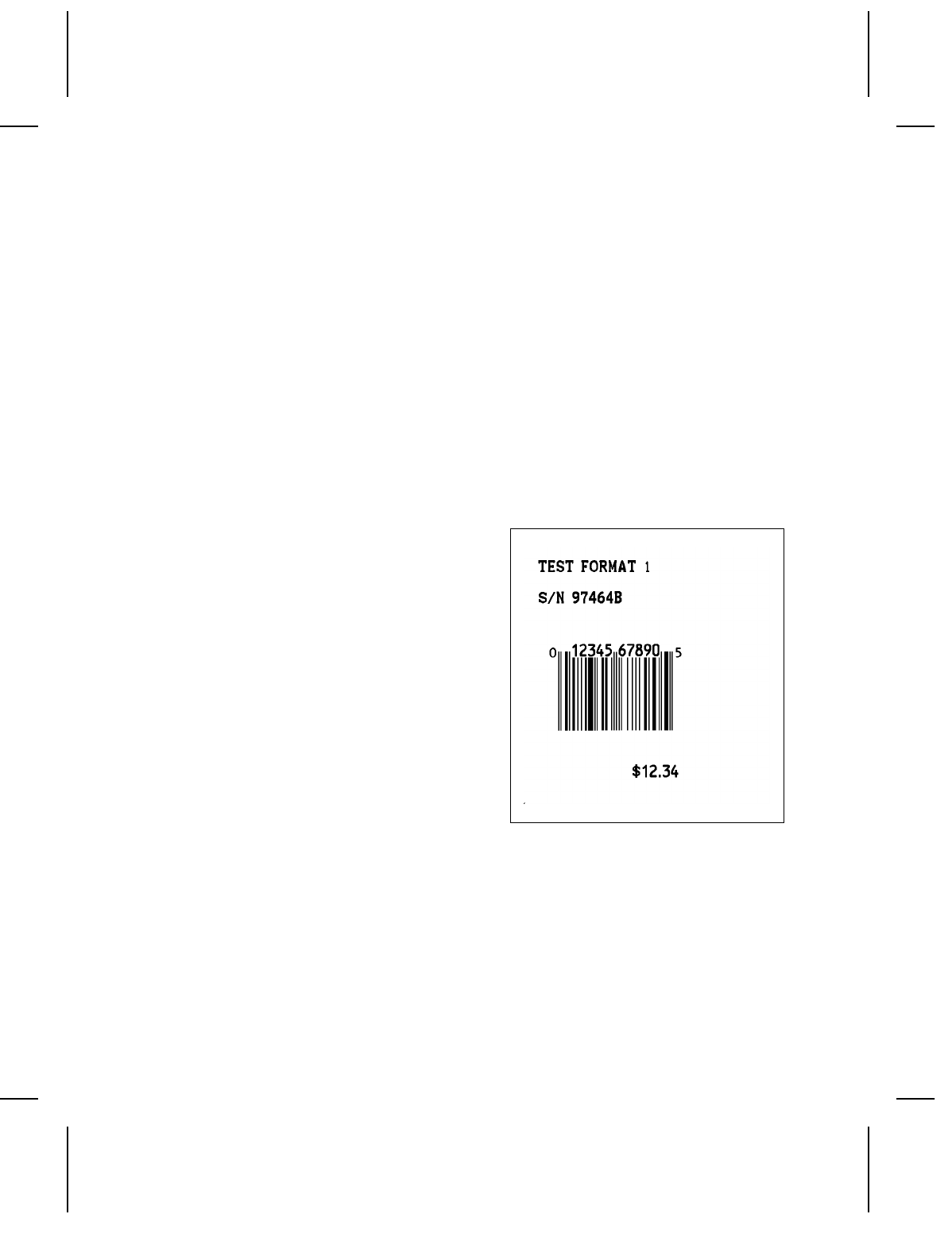
Example
This example contains data to print the label shown below.
{B1,0012,1,01,1,0,C;PTEST p
T00;TEST FORMAT1 p
T01;S/N 97464B p
T02;$12.34 p
B00;0012345678905 p }
The batch prints the phrase
"TEST FORMAT 1" in text field
T00, "S/N 97464B" in text field T01, "$12.34" in text field T02,
and "0012345678905" in bar code field B00.
If consecutive batch data streams use the same format, send only
the changed data fields. See the following section, "Using
Previously Defined Print Data."
3-22 Message Structures

Using Multiple Batches with One Format
You can send multiple batches for any format previously loaded
into the printer. To do so, send the format to the printer, then
send as many batches as you want to print data on that format.
This allows you to send multiple batches without sending a new
format with each batch.
Using Previously Defined Print Data
When sending multiple batches for one format, you can "re-use"
your print data. On consecutive batches, the data in a field does
not change, omit that field from the later batch.
When you leave out any field number that was specified in the
preceding batch, the data used in the preceding batch will print on
following batches until new field data is entered.
For example, batch 1 below prints a date in text field T01. Since
batch 1 and batch 2 are printed on the same day, batch 2 can
leave out field T01. Since T01 was defined in the preceding
batch, it will automatically print in batch 2.
Batch 1: Batch 2:
{ B12,1,0,1,1,0,C; p { B12,1,0,1,1,0,C; p
T01;12/31/90 p T02;Stock #52014
T02;Stock #43768 T03;Sprinkler }
T03;100’ Hose }
If two fields overlap, do NOT use this feature.
If fields overlap, you must send the format
before each batch.
Message Structures 3-23

Batch Separators
This command selects the use of batch separators. A batch
separator is a tag with a wide black line across the top or a
double length tag and is last tag in a batch. Your Operator’s
Handbook shows the type of batch separator used by your printer.
When printing online, add 1 to your batch quantity. The batch
separator does not add a tag to the total number of tags in a
batch. (In offline operation a batch separator increases the batch
count by one tag.)
The command structure is shown below, followed by an example.
If using this batch separator packet, make
sure the batch header "MODE" value is set to
C.
Syntax { S TYPE }
Field Contents
SMust be the letter ‘S’ to identify the batch separator selection.
TYPE A single digit to turn the batch separator selection on or off.
The resulting separator depends on the type of stacker you
are using.
3-24 Message Structures
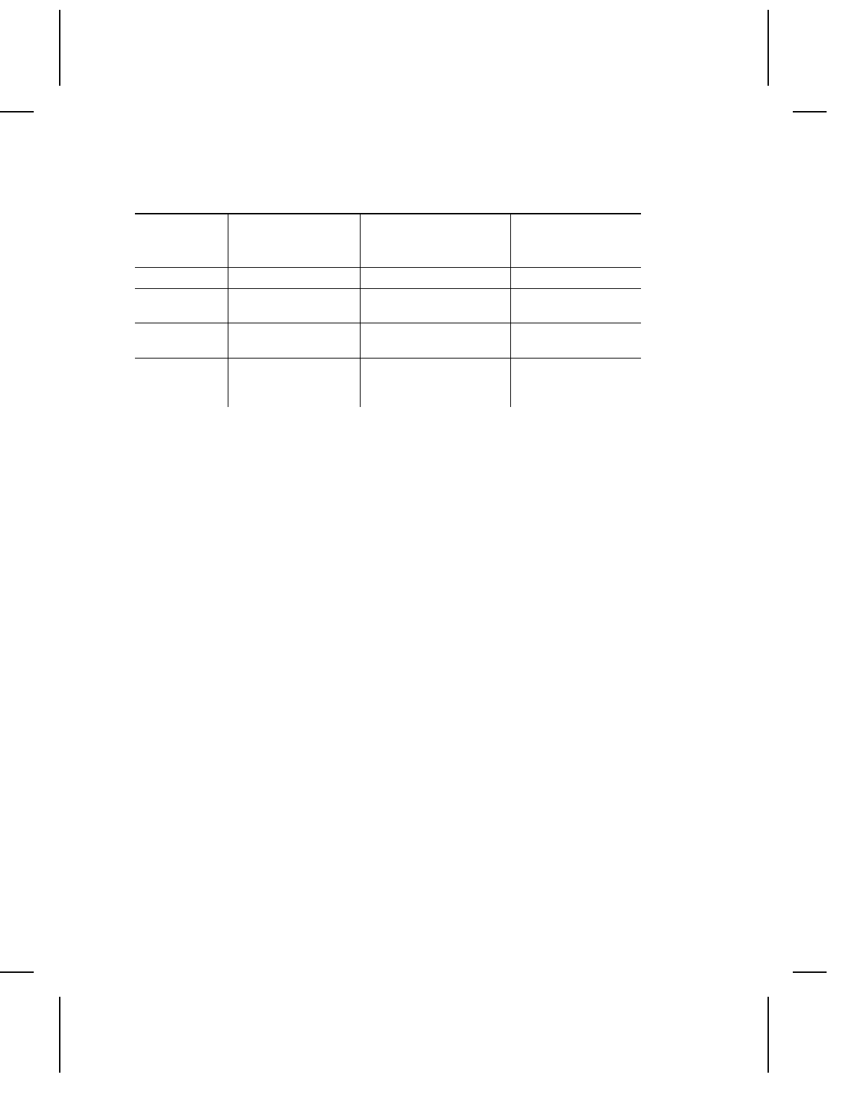
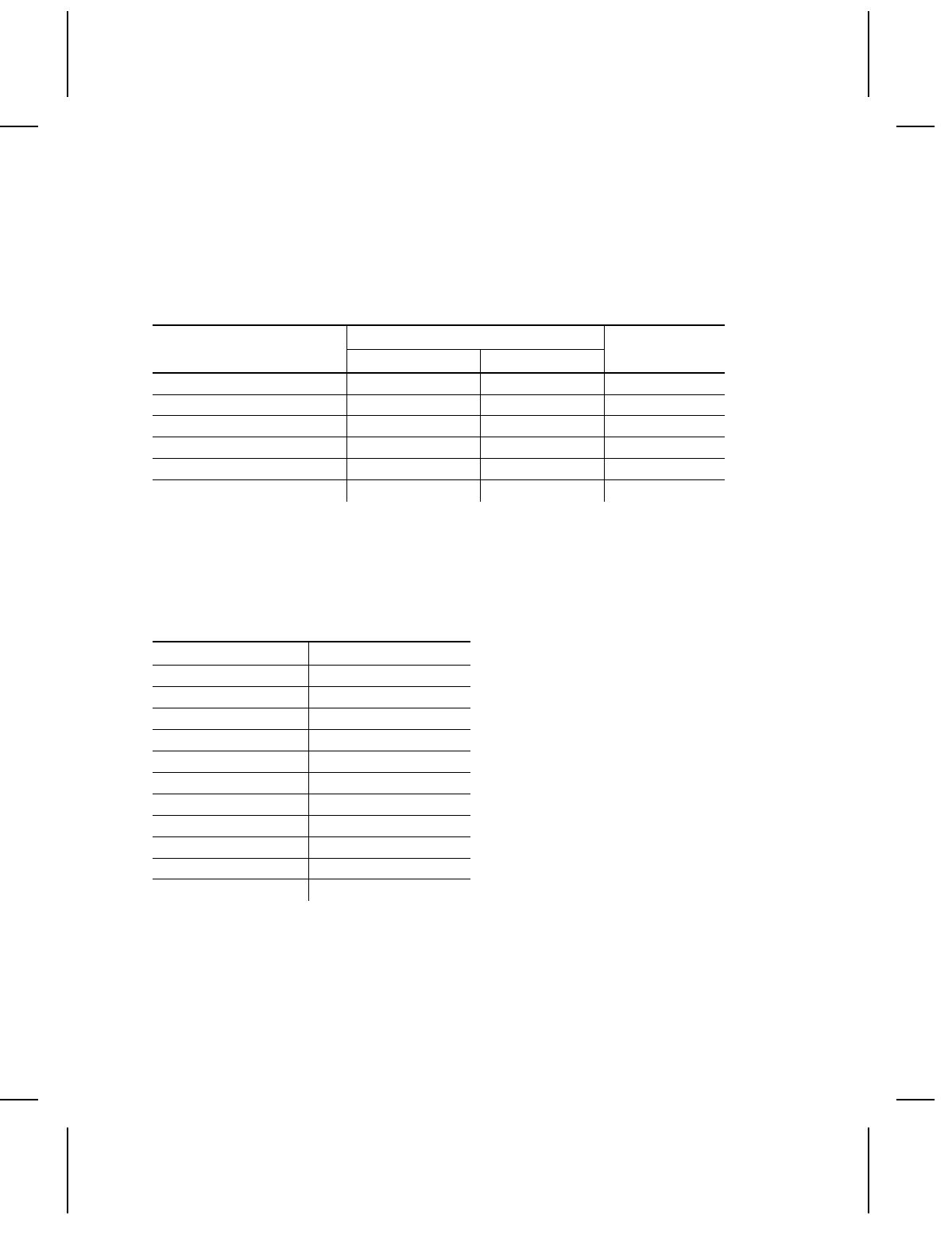
Values 0, 1, 2, or 3 as shown in the table below.
Stacker Type
Data Stream
none 920 924/925
{S0} No separator No separator No separator
{S1} Double length tag
with no stripe
3 mm extra length
tag with 6 mm stripe
Double length tag
with no stripe
{S2} Normal length tag
with 3 mm stripe
Normal length tag
with 3 mm stripe
Normal length tag
with 3 mm stripe
{S3} 3 mm extra length
tag with
6 mm stripe
3 mm extra length
tag with 6 mm stripe
3 mm extra length
tag with 6 mm
stripe
Format data stream.
{F 12, 560, 508;SMALL2IN p
T1, I, 0, 300, 50, 1, 1, 0, 0, B p
T2, I, 0, 200, 50, 1, 1, 0, 0, B p
T3, I, 0, 150, 50, 1, 1, 0, 0, B p
T4, I, 0, 100, 50, 1, 1, 0, 0, B p
T5, I, 0, 050, 50, 1, 1, 0, 0, B p }
Batch data stream.
{S0}
{B 12, 1, 0, 1, 1, 0, C;SMALL2IN p
T1;Separators off. p
T2;Line 2. p
T3;Line 3. p
T4;Line 4. p
T5;Line 5. p }
Message Structures 3-25

Turn batch separator on; print another batch.
{S1}
{B 12, 1, 0, 1, 1, 0, C;SEP.ON p
T1;Separators on. p
T2;Line 2. p
T3;Line 3. p
T4;Line 4. p
T5;Line 5. p }
Turn batch separator off.
{S0}
3-26 Message Structures

USING GRAPHICS 4
There are two stages to printing a graphic:
NCreate the data stream for the graphic image
NPlace the image into a format.
To print a format with a graphic image, transmit data to the printer
in this order:
Graphic data stream to define the graphic image
Format data stream that references the graphic image
Batch data to print the format.
Using Graphics 4-1
Defining Graphic Image Data
Graphic images are created by a series of dots printed in a
specific pattern. This pattern results from a process of turning
dots "ON" or "OFF" on the printhead.
We will use the terms "black dots" to describe a dot that is ON,
and "white dots" for a dot that is OFF.
This section describes how to build a data stream to create this
pattern with your printer.
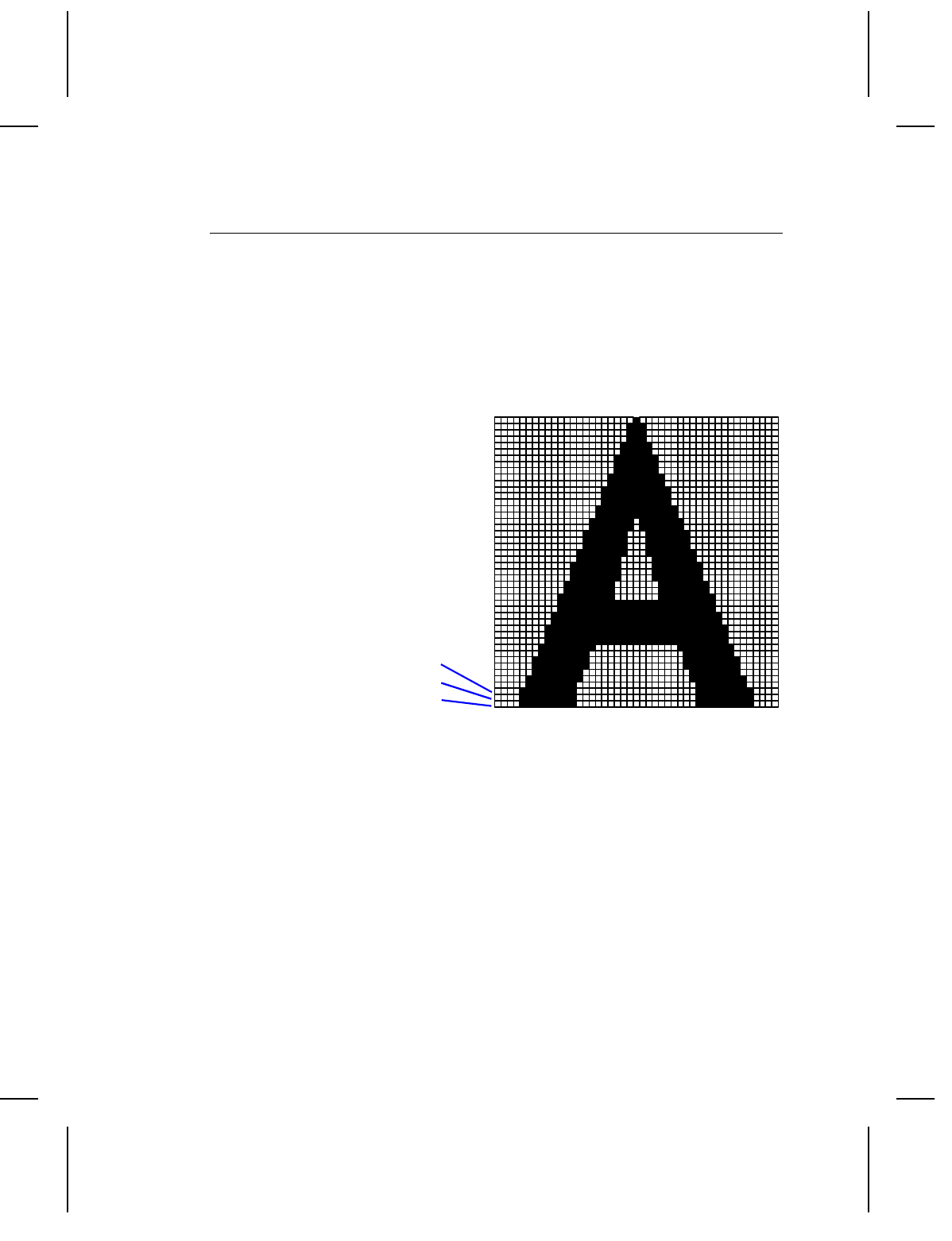
This example shows
how black dots and
white dots form an
image of the letter A.
To create a data stream for this image, start with the bottom row.
Count the number of white dots and black dots, in order of
appearance in each row.
For example, rows 1 through 4 (at the bottom) in the image above
have these dot counts:
Row 1: 4 White, 8 Black, 19 White, 8 Black, 4 White
Row 2: 4 White, 8 Black, 19 White, 8 Black, 4 White
Row 3: 4 White, 8 Black, 19 White, 8 Black, 4 White
Row 4: 5 White, 7 Black, 19 White, 7 Black, 5 White
Row 3
Row 2
Row 1
4-2 Using Graphics
The data stream uses letters to identify dot counts.
NCAPITAL letters represent black dots.
Nlowercase letters represent white dots.
Using the chart below, the data stream for row 1 would be:
Dot count:
Row 1: 4 White, 8 Black, 19 White, 8 Black, 4 White
Data Stream:
dHsHd p
(4 white = d, 8 black = H, 19 white = s)
Use multiple letter codes to indicate strings of same-color dots.
For example: 30 black dots = ZD
9 white dots = ccc
Coding Chart
Black Dots White Dots
#dots Code # dots Code # dots Code # dots Code
1A14N1a14n
2 B 15 O 2 b 15 o
3C16P3c16p
4D17Q4d17q
5E18R5e18r
6F19S6 f19s
7G20T7 g20t
8H21U8h21u
9I22V9i22v
10 J 23 W 10 j 23 w
11 K 24 X 11 k 24 x
12 L 25 Y 12 l 25 y
13 M 26 Z 13 m 26 z
The graphic data stream contains a graphic header record
followed by data streams for each row of dots in the image.
Using Graphics 4-3

Syntax
{G##,0,0,0,0 p
;...dot codes... p
;...dot codes... p
;...dot codes... p
.
.
.}
Field Contents
G## Must begin with the letter ’G’ to identify this as a graphic data
stream.
The G is followed by a one or two digit number to identify the
graphic image. Later you will use this number to insert the
graphic into a format.
Values: 0-99
NOTE: If this graphic is used in offline batch entry, the printer
assigns a name of GPH## where ## is the ID number
assigned here.
ROW Enter 0.
COLUMN Enter 0.
LINES Enter 0.
DOTS Enter 0.
;dot codes The first row of dot codes corresponds to the bottom row of
dots in the image. Essentially, this means you are building
the graphic image upside down in the data stream.
Note that since this record is a character string, it begins with
a semi-colon (;). You can place up to 100 characters in each
row.
Do not put any spaces in the dot code character string.
4-4 Using Graphics

Example
This graphic data stream
generates the letter A from the
grid earlier in this section. The
format and batch data streams to
print a sample tag follow the
graphic data stream.
The graphic is assigned a number
of 1 and it is 46 dots tall.
The graphic data stream uses the
same guidelines for structure and
syntax as the format data stream
does. See "Standard Syntax
Guidelines" in Chapter 3 for more
information.
{G1,0,0,0,0 p
;dHsHd p
;dHsHd p
;dHsHd p
;eGsGe p
;eHqHe p
;fGqGf p
;fHoHf p
;fHoHf p
;gGoGg p
;gHmHg p
;hGMGh p
;hGMGh p
;hGMGh p
;iFMFi p
;iFMFi p
;jEMEj p
;jEMEj p
;jEMEj p
;kHgHk p
;kHgHk p
;lGgGl p
;lHeHl p
;lHeHl p
;mGeGm p
;mGeGm p
;nGcGn p
;nGcGn p
;nGcGn p
;oFcFo p
;oGaGo p
;pFaFp p
;pFAFp p
;qEAEq p
;qEAEq p
;qEAEq p
;rDADr p
;rDADr p
;sCACs p
;sCACs p
;sCACs p
;tBABt p
;tBABt p
;uCu p
;uCu p
;uCu p
;vAv p }
Using Graphics 4-5

Placing the Image in a Format
The message structure below places a graphic field in a format.
You can have up to 100 graphic images. The graphic record can
be placed in a format data stream anywhere following the format
header record.
Graphics are counted as fields, just like text or bar code fields.
When determining the number of fields in your format, count each
graphic as a separate field.
Syntax G##, ROW, COLUMN p
If graphic fields overlap with other fields in the data stream, the
last field in the data stream will dominate.
Field Contents
G## Must begin with the letter ’G’ for a graphic field.
The G is followed by one or two digits for the graphic number.
Enter the number you assigned to the graphic in the graphic
data stream.
Values: 0-99
ROW One to four digits to define the row location of the graphic on
the supply. This is the distance from the the guide edge zero
point at the bottom of the supply and the bottom of the field.
The zero point is 1.5 mm or 0.060 inches from the bottom of
the supply. The bottom of the supply is the edge that exits the
printer first.
This value is measured in tenths of millimeters (TOMMS) and
must be less than the maximum length of the supply.
Values: 0-2032
COLUMN One to four digits to define the column location of the field on
the supply. This is the distance from the guide edge zero
point at the left edge of the supply and the left edge of the
field.
4-6 Using Graphics
The zero point is 1.5 mm or 0.060 inches from the left edge of
the supply.
The unit of measurement is tenths of millimeters. The range
must be less than the maximum width of the supply.
Values: 0-1016 (0 to 4 inches)
The following format data stream uses the graphic data defined
earlier in this chapter. The graphic is inserted 20 mm from the
bottom and 20 mm from the left edge of the supply.
{F11,550,507;LETTER-A p
G1,200,200 p
T0,I,0,400,100,1,1,0,0,B p }
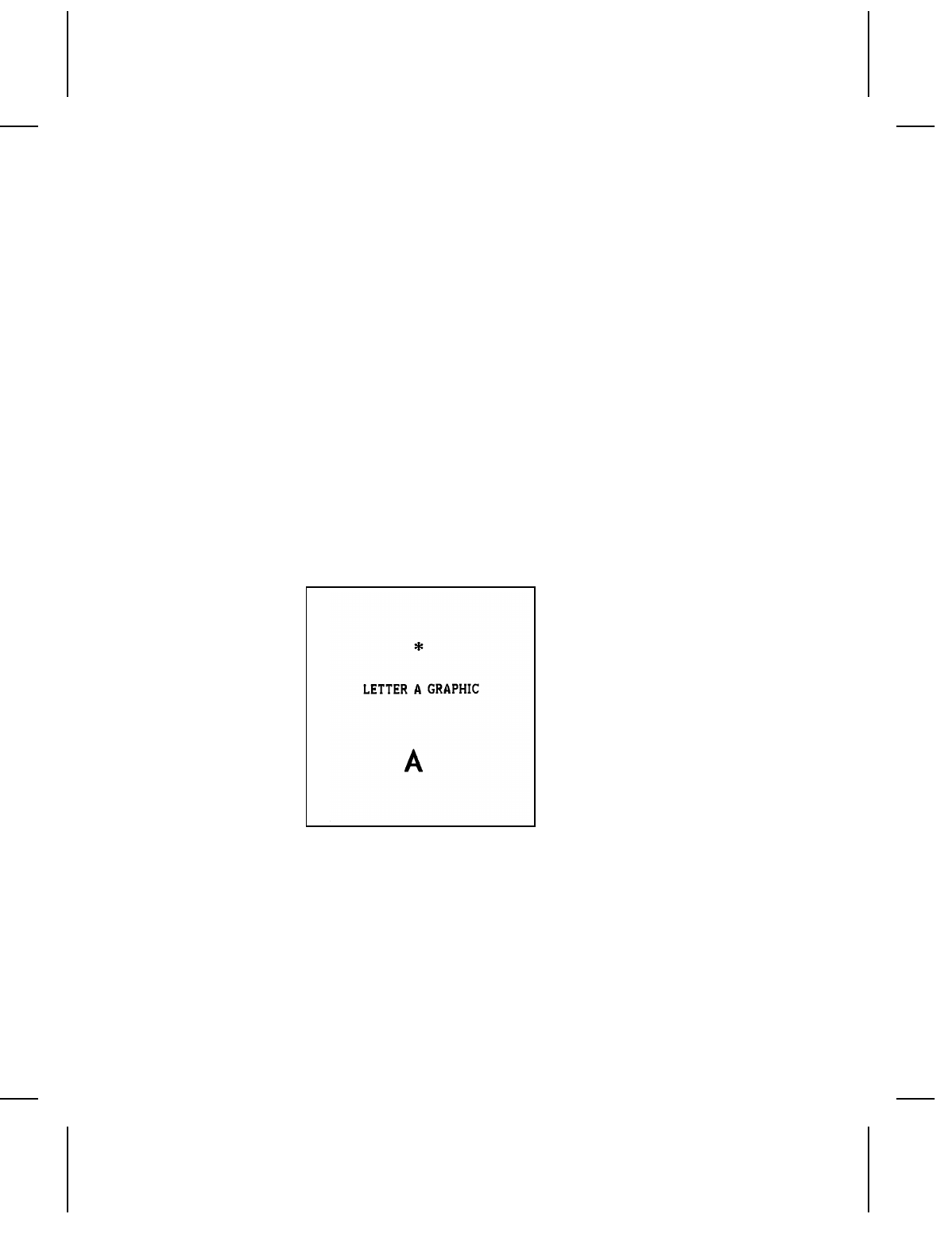
The following batch data stream prints the following tag:
{B11,1,1,1,1,0,C;LETTER-A p
T0;LETTER-A GRAPHIC p }
Example G1,100,40 p
The graphic number 1 is inserted into the format 10 millimeters
from the bottom and 4 millimeters from the left edge of the print
area.
Using Graphics 4-7

Clear Image Buffer
This command clears all or selective graphics from the image
buffer. Once graphic data is sent to the printer, that graphic stays
in memory until a clear image buffer command is sent.
Syntax { C## }
Field Contents
CMust be the letter ‘C’ to identify the clear image buffer
command.
## This optional parameter specifies a particular graphic to be
cleared from memory. It must match the number assigned in
the graphic data stream. If omitted, ALL graphics in memory
will be deleted.
Example {C} Clears all graphics from the printer.
{C4} Clears only graphic number 4.
Compressing the Data Stream
Image data usually consists of a large amount of repetitive data.
Therefore, the printer uses a data compression algorithm for the
graphic message structure. Here’s how it works.
1. Any image is defined as a matrix of cells.
2. Each row of the matrix consists of a series of consecutive ON
(black) or OFF (white) cells. The range is 1-26, represented
by adding either a hex 40 (black) or hex 60 (white). Cells that
print black are represented by the upper case letters ‘A’
through ‘Z’ in the file sent to the printer. Cells that print white
are represented by the lowercase letters ‘a’ through ‘z’ in the
file. Consecutive cells greater than 26 require multiple letters.
Example: 39 consecutive white cells are represented by
the letters ‘zm’ (i.e. ‘z’ produces 26 white
cells followed by ‘m’ or 13 more white cells).
4-8 Using Graphics

3. Each row of the matrix is terminated by the command
inter-record separator, split vertical bar ( p ). However, the last
row of the matrix ends with the TERMINATOR command,
closed brace (}).
4. In addition to compressing consecutive cells, repetitive lines
of compressed row data can be combined. For example, if
twelve rows have the same data (;zm), a number can be
added at the beginning of the line to repeat the line (;12zm).
5. The following example shows how you can compress the
"Letter A" data stream. The long version is on the left. The
compressed version of the same data stream is on the right.
Using Graphics 4-9

Long Version Compressed Version
{G1,0,0,0,0 p {G1,0,0,0,0
p
;dHsHd p ;3dHsHd
p
;dHsHd p ;eGsGe
p
;dHsHd p ;eHqHe
p
;eGsGe p ;fGqGf
p
;eHqHe p ;2fHoHf
p
;fGqGf p ;gGoGg
p
;fHoHf p ;gHmHg
p
;fHoHf p ;3hGMGh
p
;gGoGg p ;2iFMFi
p
;gHmHg p ;3jEMEj
p
;hGMGh p ;2kHgHk
p
;hGMGh p ;lGgGl
p
;hGMGh p ;2lHeHl
p
;iFMFi p ;2mGeGm
p
;iFMFi p ;3nGcGn
p
;jEMEj p ;oFcFo
p
;jEMEj p ;oGaGo
p
;jEMEj p ;pFaFp
p
;kHgHk p ;pFAFp
p
;kHgHk p ;3qEAEq
p
;lGgGl p ;2rDADr
p
;lHeHl p ;3sCACs
p
;lHeHl p ;2tBABt
p
;mGeGm p ;3uCu
p
;mGeGm p ;vAv
p
;nGcGn p }
;nGcGn p
;nGcGn p
;oFcFo p
;oGaGo p
;pFaFp p
;pFAFp p
;qEAEq p
;qEAEq p
;qEAEq p
;rDADr p
;rDADr p
;sCACs p
;sCACs p
;sCACs p
;tBABt p
;tBABt p
;uCu p
;uCu p
;uCu p
;vAv p }
4-10 Using Graphics

QUICK REFERENCES 5
Text Font Sizes
The 9474 fonts are selected in Printer Configuration in offline
mode only. Be sure the fonts selected at the printer are
compatible with the format and batch data you are downloading.
Fonts
The 9474 fonts are proportional (each character takes only as
much space as it needs). Uppercase I is the narrowest character
and results in the most characters per inch. Uppercase M is the
widest and results in the fewest characters per inch. In the
following table uppercase I was used to calculate the most
characters per inch. Uppercase M was used to calculate the
fewest characters per inch.
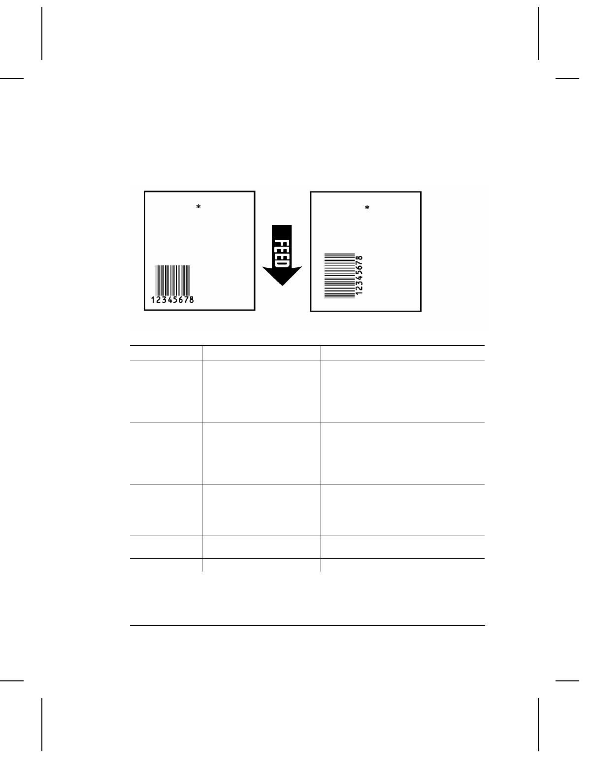
If you rotate the characters (with the top of the characters toward
the left or right side of the stock) you will get the characters per
inch shown in the table labeled "Rotated Characters."
Quick References 5-1
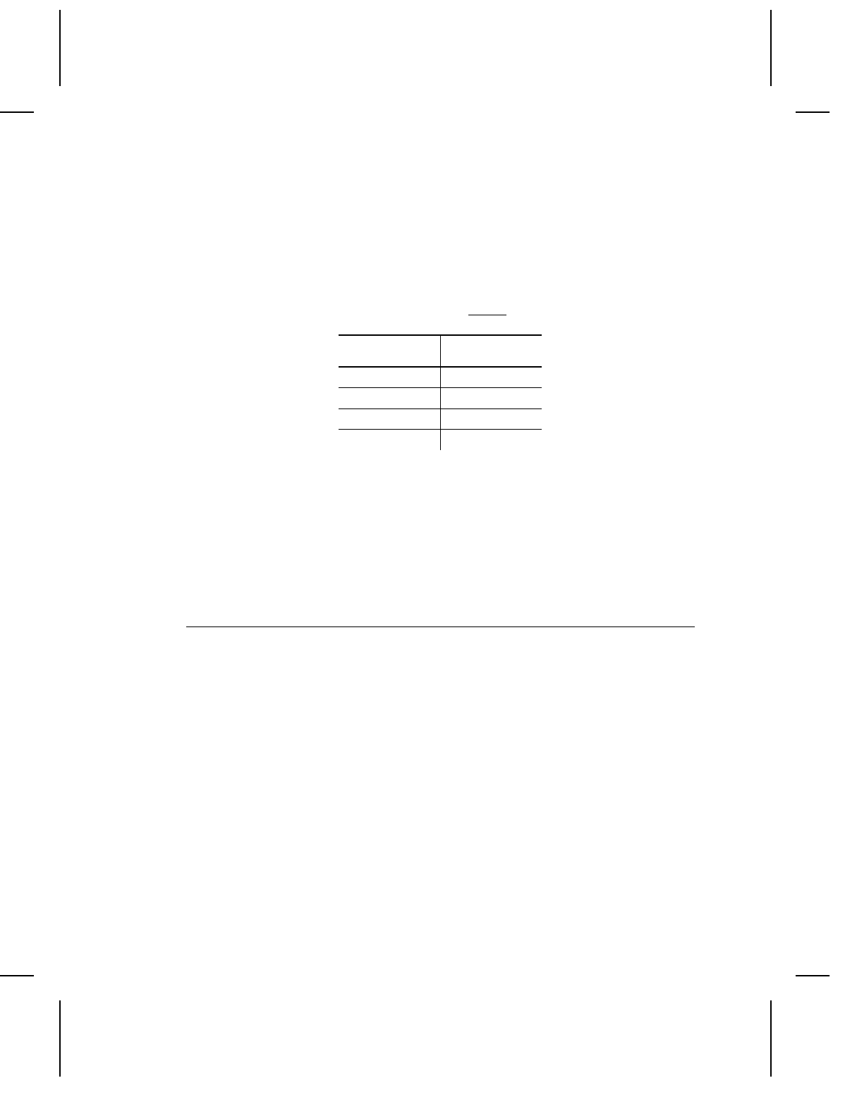
Parallel Characters
Value/Font Characters/Inch Character
Height (in.)
IM
1/Standard 21.3 12.0 0.10
2/Reduced 64.0 24.0 0.07
3/Bold 19.2 7.1 0.20
5/OCR-A 10.1 10.1 0.10
6/UPC HR1 19.2 13.7 0.10
7/UPC HR2 32.0 19.2 0.08
Rotated Characters
Font Characters/Inch
Standard 10
Reduced 14
Bold 5
OCR-A 10
Character Width (in Dots)
The dots per character is the same for all characters. The
examples below show the difference between parallel characters
and serial characters.
Serial Characters
Parallel Characters
5-2 Quick References
Parallel Character Width (in Dots)
The following table shows the character width in dots. Uppercase
I is the narrowest character (fewest dots per character).
Uppercase M is the widest character (most dots per character).
Value/Font Dots Wide ICG*
IM
1/Standard 7 14 2
2/Reduced 2 7 1
3/Bold 7 24 3
5/OCR-A 16 16 3
6/UPC HR1 12 12 2
7/UPC HR2 10 10 1
*Inter-character gap
Bar Codes
The table below lists bar code selections and values.
Value Dots Wide
1UPC-A
2UPC-E
3 Interleaved 2 of 5
4 Code 39
5 Codabar
6EAN-8
7EAN-13
8 Code 128
9MSI
10 UPC/EAN+2
11 UPC/EAN+5
Quick References 5-3
Bar Code Densities
The samples below show the difference between parallel and
serial bar codes.
Bar Code Densities
Value Bar Code Density (Char/in)
1
Code 39
I 2 of 5
Code 128*
MSI
UPC/EAN
6.63
12.02
8.74 (alphanumeric)
17.48 (numeric only)
6.87
80% standard density
2
Code 39
I 2 of 5
Code 128*
MSI
UPC/EAN
3.32
6.87
5.83 (alphanumeric)
11.66 (numeric only)
5.34
120% standard density
3
Code 39
I 2 of 5
Code 128*
MSI
4.01
4.93
4.37 (alphanumeric)
8.74 (numeric only)
4.01
4Code 39
I 2 of 5
not supported
3.01
5Code 39 6.01
*For more information on Code 128, see Appendix B.
Line Width
Serial Bar Code
Parallel Bar Code
5-4 Quick References
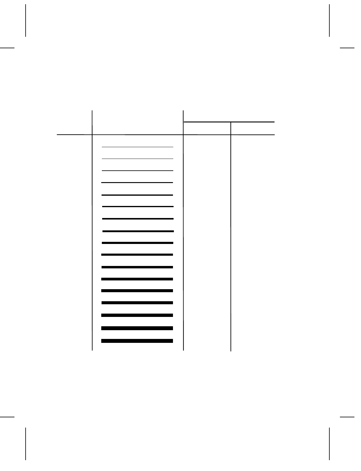
The following table shows the horizontal and vertical line widths.
Line Width
Line
Number Appearance Inches MM
1 .005 .13
2 .010 .26
3 .015 .40
4 .021 .53
5 .026 .66
6 .031 .79
7 .036 .92
8.0421.06
9.0461.16
10 .052 1.32
11 .057 1.44
12 .062 1.57
13 .067 1.70
14 .072 1.82
15 .078 1.98
Quick References 5-5
Special Characters
The following table shows the ASCII code for special characters
available in the standard font.
ASCII Code Symbol Description
~128 Hashed box
~129 Pound or Lira
~130 Yen
~131 Kronna
~132 Deutsche mark
~133 Markka
~134 Schilling
~135 Half sign
~136 Rupee
Code 128 Function Codes
The following table shows the ASCII code for the Code 128
function codes.
ASCII Code Function Code
~134 F1
~129 F2
~128 F3
~132 F4
5-6 Quick References
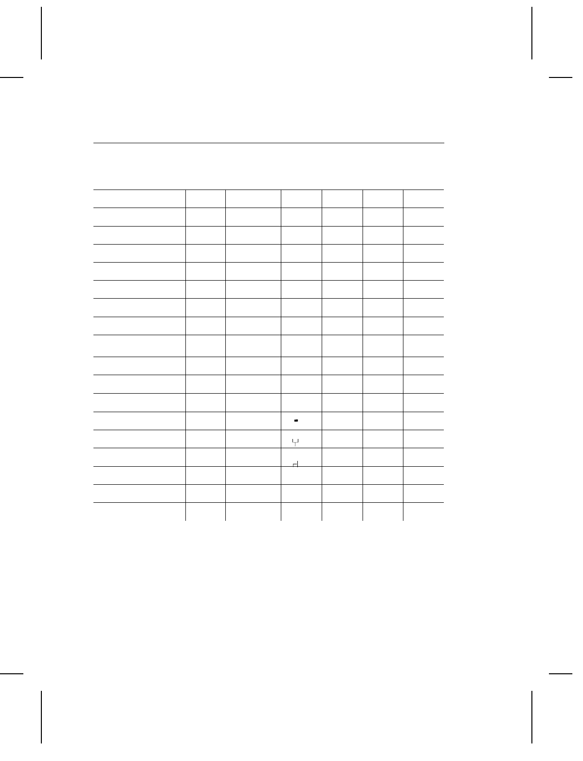
ASCII Characters
The following table shows the characters available in each font.
HR1 and HR2 are human readable fonts for bar codes.
Character Std Reduced OCRA Bold HR1 HR2
yes yes no no no no
# yes yes nononono
$ yes yes yes yes no no
% yes yes nononono
^ ¢ ¢ no¢nono
& yes yes nononono
* yes no no no no
( yes yes no yes no no
) yes yes no yes no no
[ [ yes nononono
] ] yes nononono
‘(grave) yes yes no no no no
{ yes yes nononono
} yes yes nononono
~yesyes
∫no no no
,(comma) yes yes ¬no no no
" yes yes yes no no no
— yes yes yes yes yes no
= yes yes nononono
_(underscore) yes yes no no no
+yes yes yes no no no
. yes yes yes no no
/ yes yes yes yes no no
’(apostrophe) yes yes no no no
: yes yes no yes no no
; yes yes nononono
yes yes yes no no no
yes yes yes no no no
? yes yes nononono
\yesyes¥¥nono
| no no nononono
0-9 yes yes yes yes yes yes
A-Z yes yes yes yes no HN*
a-z yes yes no no no no
yes = what you enter is what prints.
no = character does not exist in this font; nothing prints.
* Uppercase H and N are the only alphabetic characters that print in the Human Readable
fonts. All other characters are numeric.
Printable Characters by Font
Quick References 5-7
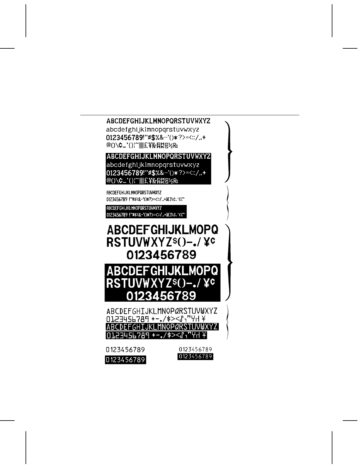
Following are the printable characters (not at actual size). Human
Readable 1 and Human Readable 2 are not available offline.
English/Metric Conversion
Standard
Reduced
Bold
OCR-A
Human
Readable (HR2)
Human Readable
(HR1)
5-8 Quick References

Inches TOMM Inches TOMM Inches TOMM Inches TOMM
- - 0.060 15 0.075 19 0.100 25
0.125 31 0.150 38 0.175 44 0.200 50
0.225 57 0.250 63 0.275 70 0.300 76
0.325 82 0.350 89 0.375 95 0.400 101
0.425 108 0.450 114 0.475 121 0.500 127
0.525 133 0.550 140 0.575 146 0.600 152
0.625 159 0.650 165 0.675 171 0.700 178
0.725 184 0.750 191 0.775 197 0.800 203
0.825 209 0.850 216 0.875 222 0.900 228
0.925 235 0.950 241 0.975 247 1.000 254
1.025 260 1.050 267 1.075 273 1.100 279
1.125 286 1.150 292 1.175 298 1.200 305
1.225 311 1.250 317 1.275 324 1.300 330
1.325 336 1.350 343 1.375 349 1.400 356
1.425 362 1.450 368 1.475 375 1.500 381
1.525 387 1.550 394 1.575 400 1.600 406
1.625 413 1.650 419 1.675 425 1.700 432
1.725 438 1.750 445 1.775 450 1.800 457
1.825 463 1.850 470 1.875 476 1.900 483
1.925 489 1.950 495 1.975 502 2.000 508
2.025 514 2.050 520 2.075 527 2.100 533
2.125 540 2.150 546 2.175 552 2.200 558
2.225 565 2.250 571 2.275 578 2.300 584
2.325 590 2.350 597 2.375 603 2.400 609
2.425 616 2.450 622 2.475 628 2.500 635
2.525 641 2.550 648 2.575 654 2.600 660
2.625 667 2.650 673 2.675 679 2.700 686
2.725 692 2.750 698 2.775 705 2.800 711
2.825 717 2.850 724 2.875 730 2.900 736
2.925 743 2.950 749 2.975 755 3.000 762
3.025 768 3.050 775 3.075 781 3.100 787
3.125 794 3.150 800 3.175 806 3.200 813
3.225 819 3.250 825 3.275 832 3.300 838
3.325 844 3.350 850 3.375 857 3.400 863
3.425 869 3.450 876 3.475 882 3.500 889
Inches TOMM Inches TOMM Inches TOMM Inches TOMM
3.525 895 3.550 902 3.575 908 3.600 914
3.625 921 3.650 927 3.675 933 3.700 939
3.725 946 3.750 952 3.775 959 3.800 965
3.825 971 3.850 978 3.875 984 3.900 990
3.925 996 3.950 1003 3.975 1009 4.000 1016
4.025 1022 4.050 1028 4.075 1035 4.100 1041
4.125 1048 4.150 1054 4.175 1060 4.200 1067
4.225 1073 4.250 1079 4.275 1086 4.300 1092
Quick References 5-9
4.325 1099 4.350 1105 4.375 1111 4.400 1118
4.425 1124 4.450 1130 4.475 1137 4.500 1143
4.525 1149 4.550 1156 4.575 1162 4.600 1168
4.625 1175 4.650 1181 4.675 1187 4.700 1194
4.725 1200 4.750 1206 4.775 1212 4.800 1219
4.825 1225 4.850 1232 4.875 1238 4.900 1245
4.925 1251 4.950 1257 4.975 1263 5.000 1270
5.025 1276 5.050 1283 5.075 1289 5.100 1295
5.125 1302 5.150 1308 5.175 1314 5.200 1321
5.225 1327 5.250 1333 5.275 1340 5.300 1346
5.325 1352 5.350 1359 5.375 1365 5.400 1371
5.425 1378 5.450 1384 5.475 1390 5.500 1397
5.525 1403 5.550 1409 5.575 1416 5.600 1422
5.625 1429 5.650 1435 5.675 1441 5.700 1448
5.725 1454 5.750 1460 5.775 1467 5.800 1473
5.825 1479 5.850 1486 5.875 1492 5.900 1499
5.925 1505 6.950 1511 5.975 1518 6.000 1524
6.025 1530 6.050 1537 6.075 1543 6.100 1549
6.125 1556 6.150 1562 6.175 1568 6.200 1575
6.225 1581 6.250 1588 6.275 1594 6.300 1600
6.325 1606 6.350 1613 6.375 1619 6.400 1626
6.425 1632 6.450 1638 6.475 1644 6.500 1651
TOMM = Tenths of millimeters
5-10 Quick References

ERROR MESSAGES 6
This chapter provides explanations of your printer’s errors. There
are four types of errors:
Ndiagnostic
Nstartup
Noperation
Noffline
If you have problems loading supplies or performing maintenance,
refer to the Operator’s Handbook. If you have a problem you can’t
solve, contact your Monarch service representative.
Before you call...
NSelect Version from the main menu and press e . The
screen displays information about the software installed in
your machine.
NWrite down the information and give it to the service
representative when you call.
Error Messages 6-1

Diagnostic Messages
These messages appear if the printer fails internal testing. If the
printer stops at one of these messages, turn the power off. Then
turn it on again. If the problem persists, call Monarch Service.
Message
Error - Turn power off
Wait 10 seconds, then turn on
Head test failure
RAM read/write failure.
ROM checksum failure.
Startup Messages
The printer displays the following messages when you turn the
power on. Messages are listed in the order they appear.
If the printer stops at one of these messages, turn the power off.
Wait at least 10 seconds, then turn it on again. If the problem
persists, call Monarch Service.
Message Description/Action
Copyright (c) 1988-89
Monarch Marking (Model 94##)
A copyright statement for
the software.
Select Supply Type: B
A)lign, B)lack Mark or D)ie Cut
Press e if you are
using black mark or
aperture supplies.
Type D and press e if
you are using die cut
supplies.
Type A and press e
to calibrate the printer.
6-2 Error Messages

Message Description/Action
Enter new date: 01/01/89
(MM/DD/YY)
Press e to keep the
date shown or to skip the
prompt.
Enter a new date in the
format shown in
parentheses and
press e .
Service Required: XXX
dayton:(800)231-7700 Press ENTER.
Preventative maintenance
message that is displayed
when the counter reaches
three million inches. This
message is displayed
every time the printer is
powered up until the
counter is reset by a
service technician.
Enter new time: 00:01:04
(HH:MM:SS)
Press e to keep the
time shown or to skip the
prompt.
Type new time and press
e . Enter the time in
the format shown in
parentheses and
press e .
"Head test failure"
message appears.
Check for visible print
problems. Continue
printing or call Service.
If the print problem is in a
bar code, call Monarch
Service. You can check
the quality of your bar
code if you have a bar
code verifier.
Error Messages 6-3

Operation Messages
There are two kinds of operation messages:
NError messages
NWarning messages
The messages use the following formats:
ERROR: (function)
Error description text.
WARNING: (function)
Warning message text.
Function indicates the part of the program
where the error originated, such as Batch
Control or Format Entry.
Warning and error messages can be:
Informative
messages
The printer displays an informative message
for several seconds, then resumes operating.
An informative message is usually displayed
for 3 seconds in offline operation and for 10
seconds in online operation.
Or ...
Failure
messages
The printer displays a failure message and
stops operating until the operator presses
e.
6-4 Error Messages

Printer Errors
These messages occur during online or offline operation.
General Warnings
These warning messages are listed in alphabetical order.
Message Description/Action
Demand is not
available.
You tried to change the print mode in Printer
Options. On Demand printing is not available
on a printer with a knife.
Load supply and
press ENTER.
The next batch to print needs a different
supply than what is loaded.
Load the right supply and press e .
Printing suspended
until exit.
While printing, you have selected Batch
Control to check the print queue. Printing will
resume when you exit Batch Control.
Unassigned
memory recovered.
You turned the printer off before it completed
the task in progress. You see this message
when you turn the printer back on.
Check all stored items (formats, batches,
passwords, graphic files, etc.) for missing or
bad data before continuing.
General Errors
These messages are listed in alphabetical order.
Message Description/Action
Access denied. You entered an invalid password.
Error Messages 6-5

Message Description/Action
Cannot cancel. You cannot cancel the batch in its current
state. You can only cancel a batch that has a
status of P (Print) or I (Image). (You can use
delete if you want to remove a batch with any
other status.)
Cannot delete. You cannot delete the batch in its current
state. You can only delete a batch that has a
status of Q (Queue). (You can use cancel if
you want to remove a batch with a P or I
status.)
Duplicate cost
code character.
A character appears more than once in the
Entered Char portion of your cost code.
Type the cost code again, without repeating
any characters.
Field ## bad
font/barcode.
The font or barcode for the field number
shown (##) is not defined properly.
Check the field definition in Format Entry and
correct the field.
Field ## invalid
data.
The data includes characters not available in
the character set specified for this field.
Check the field definition in Format Entry for
the valid font.
Field ## graphic
missing.
You have requested a graphic that is not
available; the file has not been downloaded
from the host.
Download the graphic file and request the
graphic again or request another graphic.
6-6 Error Messages

Message Description/Action
Field ## extends
off tag.
The field you are defining does not fit on the
tag.
Change the field location, rotation, or font
size so it fits on the tag.
Head open. The ribbon is improperly positioned.
Reposition the cassette or ribbon loading
device so it is firmly seated. Close the print
head.
Hot head. The print head is too hot to operate. This is
normally due to continual printing of formats
with a lot of printed data (more than 30% of
the tag contains print).
Let the printer cool before continuing.
Insufficient
memory.
There is not enough memory available for the
item you are trying to store.
Delete formats or batches to free memory.
Knife jam. The knife is jammed or blocked, or you are
attempting to cut supply that is smaller than
1.2 inches.
Clear the knife, then try to print again. If
supply is too small, press 1 to override the
message and load the correct supply before
attempting to print.
Merge assimilation
error.
You have made an error in defining a merge
field.
Enter the merge field again to correct it.
No batches to
examine.
Batch Control is available only when there are
batches in the print queue.
Error Messages 6-7

Message Description/Action
No formats
available to print.
You cannot enter Data Entry mode until a
format is defined.
Ribbon problem. The ribbon cassette is depleted or jammed.
The ribbon may be broken. Check the ribbon
and reload or replace it if necessary.
Stacker Fault. The stacker is full or the stacker track is
jammed. Empty the stacker before trying to
print again.
Supply problem. There is a problem with the feed mechanism.
Reload the supply if necessary.
The 9474 will also display this
message if the backing paper takup reel is
full, the printer is out of stock, or the stock is
the incorrect size for the format that was
loaded.
Communication Errors
The following errors are caused by communication problems in
the printer.
Message Description/Action
All comm
channels busy.
Software Error. Call Monarch Service.
Invalid comm
channel.
Software Error. Call Monarch Service.
Invalid file type. Software Error. Call Monarch Service.
Receive buffer full. The host did not stop transmission after it
received an XOFF character or after DTR
went inactive. Check communication setup at
the host.
6-8 Error Messages

Message Description/Action
Receive framing
error.
Host communication protocol doesn’t match
machine. Check communication setup at the
host.
Receive overrun
error.
Host communication protocol doesn’t match
machine. Check communication setup at the
host.
Receive parity
error.
Host communication protocol doesn’t match
machine. Check communication setup at the
host.
Offline Messages
Data Entry or Test Print Errors
The following errors occur during data entry or test printing. The
messages are listed in alphabetical order.
Message Description/Action
CD verify failed. You entered an incorrect check digit in a field
that requires a check digit.
Improper field
length.
You are trying to enter an invalid number of
characters in a Fixed or Optional/Fixed field.
A Fixed field requires exactly the number of
characters shown by the dashes on the
screen. An Optional/Fixed field requires
either the exact number of characters shown
by the dashes on the screen, or 0 characters.
Enter the correct number of characters for the
field.
Error Messages 6-9

Message Description/Action
Invalid cost code
character(s).
You are trying to enter characters in a cost
code field (in Data Entry) that are not defined
in the cost code. Check your data to be sure
it is correct, then enter the data again.
Machine busy. You are trying to print a test tag, but the print
queue is not empty. The print queue must be
empty to perform a test print. Wait until all
batches have printed, then try again to print
the test tag.
Must be all digits. You are trying to enter non-numeric
characters in a UPC, I 2 of 5, EAN, or MSI
bar code field. You can only enter numeric
data for these fields. Check your data to be
sure it is correct, then enter the data again.
Must be an even
# of characters.
You are trying to enter an odd number of
characters for an I 2 of 5 bar code field.
Check your bar code data to be sure it is
correct, then enter the data again.
No fields defined. You are trying to print a test tag, but you have
no fields defined. You must define at least
one field before you can test a format.
Price CD verify
failed.
You entered incorrect data in a UPC or EAN
bar code field. Check your data to be sure it
is correct, then enter the data again.
Typing mismatch. You are trying to enter data for a Verify field
(you must enter the same data twice), but
your entries do not match. Check your data
to be sure it is correct, then enter the data
again.
6-10 Error Messages

Format Entry Errors
Message Description/Action
CD scheme not
defined.
You selected a check digit scheme number in
Format Entry that is not defined. Define the
check digit scheme in Printer Configuration.
Cannot save
format.
You have not completed any field definitions
for this format.
Format in use.
Cannot delete.
You are trying to delete a format used by a
batch that is printing or waiting to print. Be
sure you are trying to delete the right format.
Wait until the batch that uses the format has
printed, then delete the format.
Format in use.
Cannot modify.
You are trying to modify a format used by a
batch that is printing or waiting to print. Be
sure you are trying to modify the right format.
Wait until the batch that uses the format has
printed, then modify the format.
I 2 of 5 requires
even # of digits
You are trying to define the field length for an
I 2 of 5 barcode as an odd number. Define
the field length as an even number of
characters.
Improper field
length.
You are trying to define a field length as
greater than 30 characters or as 0 characters.
All fields must be 1-30 characters (except
merge fields, which may not exceed 26
characters). Re-define the field length
correctly.
Incompatible field
for merge.
You tried to use a line field or a graphic field
in a merged field. You cannot use these field
types as part of a merged field.
Error Messages 6-11

Message Description/Action
Incompatible field
for sub.
You tried to use a line field or a graphic field
in a subfield. You cannot use these field
types as part of a subfield.
Invalid barcode
height.
You tried to define a bar code height as less
than 0.20 inch. Bar codes must be at least
0.20 inch (5.08 mm or 38 dots) in height.
Invalid field
reference.
You are trying to define a subfield or a
merged field. You have chosen a link with a
field number greater than the subfield or
merged field. Choose a link with a field
number less than the merged field.
Invalid
magnification
value.
You entered a font magnification value that is
outside the valid range of 1-10.
Invalid supply
length
The specified supply length is longer or
shorter than the printer can print.
Invalid supply
width.
The specified supply width is wider or
narrower than the printer can print.
Invalid thickness
value.
You are defining a line field. You entered a
value for the line width that is outside the
valid range of 1-15.
Merge field limit
is 26 chars.
You are trying to define a merged field with a
field length of more than 26 characters.
Scheme # uses
# marked chars.
You are defining a check digit field and you
have selected a check digit scheme (#). The
number of characters you marked is wrong for
the scheme you chose. Be sure you have
selected the right check digit scheme, then
mark the characters again.
6-12 Error Messages

Message Description/Action
Scheme # uses
# CD(s).
You are defining a check digit field and you
have selected a check digit scheme (#). The
number of characters you marked is wrong for
the scheme you chose. Be sure you have
selected the right check digit scheme, then
mark the check digits again.
Stop location
out of range.
You are defining a line field, and have given a
stop location that is off the tag. Check your
format and enter the correct stop location.
Sub/merge
requires this field.
You are trying to delete a field that is part of a
subfield or a merged field. Be sure you are
trying to delete the right field. Remove the
field you want to delete from the subfield or
merged field. Then try to delete the field
again.
Vertical/Horizontal
out of range.
You entered a field location in Format Entry
that is outside the dimensions of the format.
Check the location of the field you are
defining to be sure it fits on the tag, then
enter the location again.
Online Messages
The following messages occur during online communication when
the transmitted data contains errors. To recover from the error,
correct the data, then re-transmit it.
Online Warnings
Message Description/Action
Column > format
width.
The column definition for a field location is
greater than the format width definition.
Error Messages 6-13

Message Description/Action
Column > head
width.
The column definition for a field location is
greater than the width of the printhead.
Data string
too long.
The data string length exceeds 30 characters.
Format for batch
not found.
The format for the batch being sent has not
been downloaded.
Graphic not found. The graphic specified for a field has not been
downloaded.
Identifier
out-of-range.
The format, batch, line, or graphic identifiers
are out of range.
Invalid barcode
field.
Insufficient or incorrect data was used to
create a barcode field.
Invalid command. An unknown command was received.
Invalid cut value. The cut value is not 0 or 1.
Invalid data field. A field specified to receive data does not
exist on the format. The batch is not created.
Invalid incr/decr
value.
The increment/decrement value is outside
the valid range of 0-999.
Invalid label length. The specified supply length is longer or
shorter than the printer can print.
Invalid label width The specified supply width is wider or
narrower than the printer can print.
Invalid number of
parts value.
The number of parts value is outside the valid
range of 1-5.
6-14 Error Messages

Message Description/Action
Invalid orientation
value.
The line or character orientation value is not
0 or 1.
Invalid separator
value.
The batch separator value is outside the valid
range of 0-3.
Invalid text field. Insufficient or incorrect data was used to
create a text field.
Invalid thickness
value.
The line thickness value is outside the valid
range of 1-15.
Name descriptor
too long.
The format or batch name is longer than 8
characters.
No field to create
format.
The format you are sending contains no fields.
Qnty/Mult
out-of-range.
The print quantity or print multiple is outside
the valid range of 1-4 digits.
Row > format
length.
The row definition for a field location is
greater than the format length.
Row > stock
length.
The row definition for a field location is
greater than the supply length.
Stop location
out-of-range.
The stop location for a line field is off the tag
or the stop location is the same as the start
location.
Error Messages 6-15

Online Communication Errors
These errors are caused by communication problems between the
host computer and the printer during online operation.
Message Description/Action
All comm
channels busy.
Software Error. Call Monarch Service.
Invalid comm
channel.
Software Error. Call Monarch Service.
Invalid file type. Software Error. Call Monarch Service.
Receive buffer full. The host did not stop transmission after it
received an XOFF character or after DTR
went inactive. Check communication setup at
the host.
Receive framing
error.
Host communication protocol doesn’t match
machine. Check communication setup at the
host.
Receive overrun
error.
Host communication protocol doesn’t match
machine. Check communication setup at the
host.
Receive parity
error.
Host communication protocol doesn’t match
machine. Check communication setup at the
host.
Waiting for
command
terminator. Press
F1 to abort
download.
No data is being received from the host.
Check to see if the host or the
communications line is down. Press 1 to
discontinue communications (the batch or
format data will be lost and must be
retransmitted).
6-16 Error Messages

SAMPLE DATA STREAMS A
This appendix contains sample data streams for formats, batches,
and graphics. The illustrations show the tags that are printed from
these data streams.
Sample Data Streams A-1
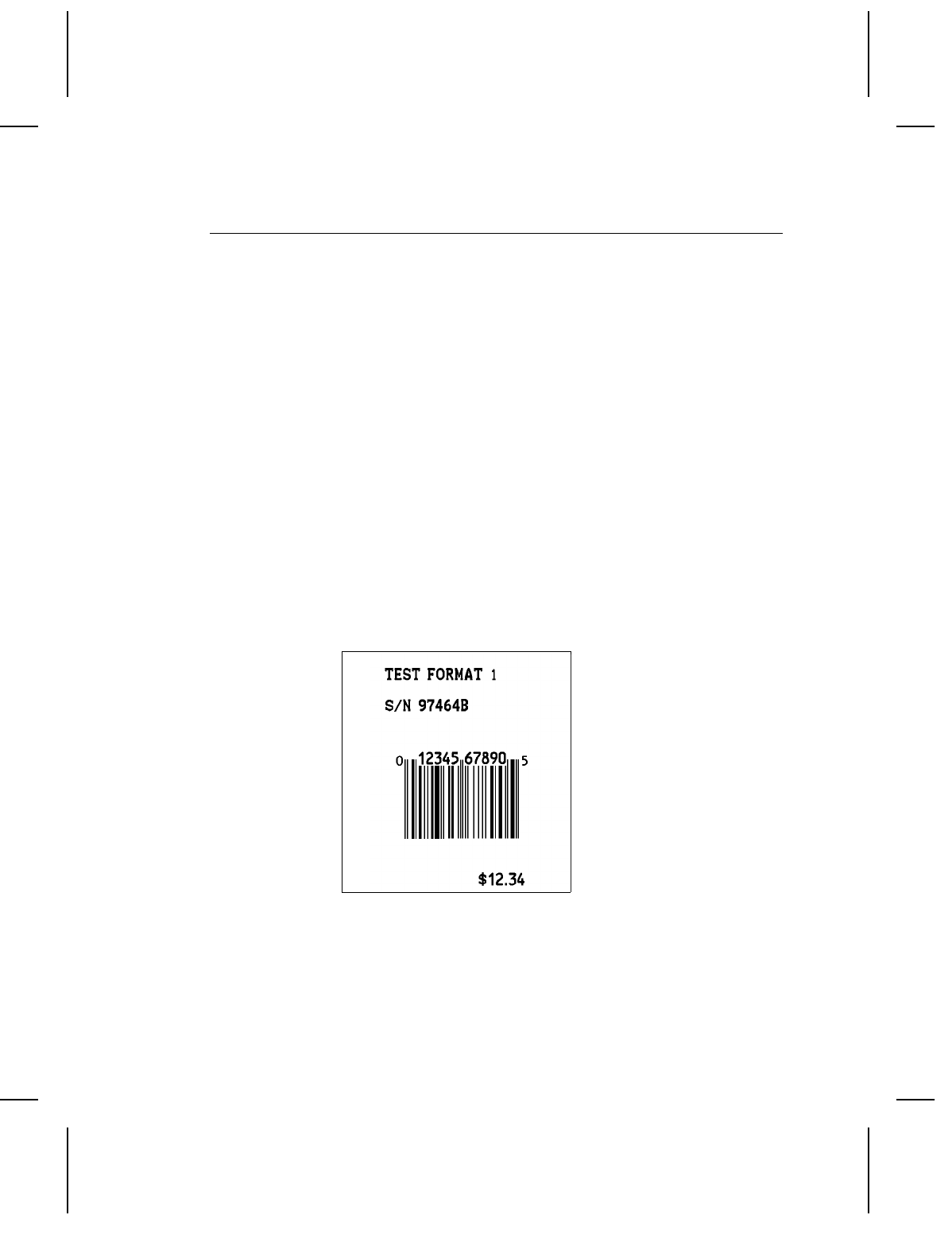
Formats, Text and Bar Code Fields
This example shows a standard format with three text and one bar
code field.
Sample Format Data Stream
{F1,0550,0507;ONLINE p
T00,I,000,0475,0050,1,1,0,0,B p
T01,I,000,0406,0050,1,1,0,0,B p
T02,I,000,0017,0253,1,1,0,0,B p
B00,I,000,0124,0093,1,1,0,0177,1 p }
Sample Batch Data Stream
{B1,2,3,1,1,0,c;BATCH1 p
T00;TEST FORMAT 1 p
T01;S/N 97464B p
T02;$12.34 p
B00;0012345678905 p }
A-2 Sample Data Streams
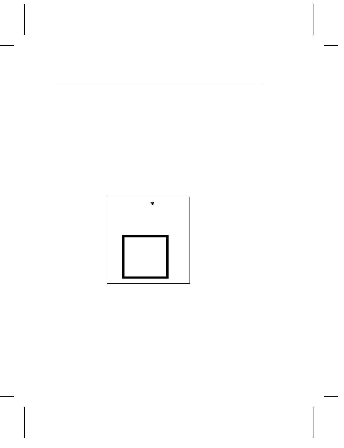
Line Fields
This example shows how to use line fields to create a box.
Sample Format Data Stream
{F2,0550,0507;BOX p
L0,50,50,0,304,10 p
L1,50,50,1,304,10 p
L2,50,304,0,304,10 p
L4,304,50,1,316,10 p }
Sample Batch Data Stream
{B2,1,0,1,1,1,C;BOXTEST p }
Sample Data Streams A-3

Graphic Images
This Graphic data stream precedes the format that uses it.
Sample Graphic Data
Stream
{G3,0,0,0,0 p
;dHsHd p
;dHsHd p
;dHsHd p
;eGsGe p
;eHqHe p
;fGqGf p
;fHoHf p
;fHoHf p
;gGoGg p
;gHmHg p
;hGMGh p
;hGMGh p
;hGMGh p
;iFMFi p
;iFMFi p
;jEMEj p
;jEMEj p
;jEMEj p
;kHgHk p
;kHgHk p
;lGgGl p
;lHeHl p
;lHeHl p
;mGeGm p
;mGeGm p
;nGcGn p
;nGcGn p
;nGcGn p
;oFcFo p
;oGaGo p
;pFaFp p
;pFAFp p
;qEAEq p
;qEAEq p
;qEAEq p
;rDADr p
;rDADr p
;sCACs p
;sCACs p
;sCACs p
;tBABt p
A-4 Sample Data Streams
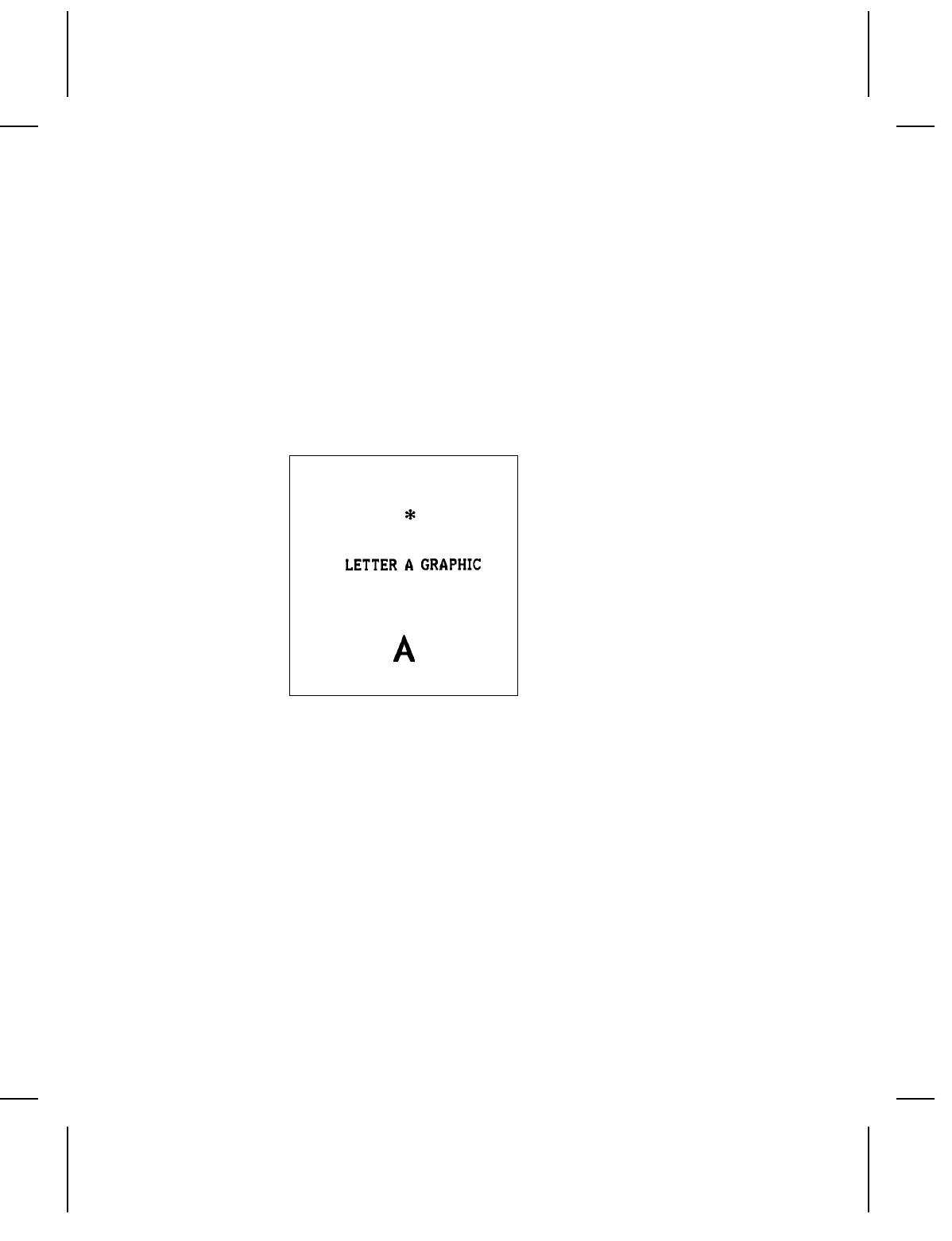
Sample Format Data Stream
{F3,0550,0507;GRAPHIC p
T0,I,0,400,100,1,1,0,0,B p
G3,200,200 p }
Sample Batch Data Stream
{B3,1,1,1,1,0,1;LETTER-A p
T0;LETTER A GRAPHIC p }
Sample Data Streams A-5
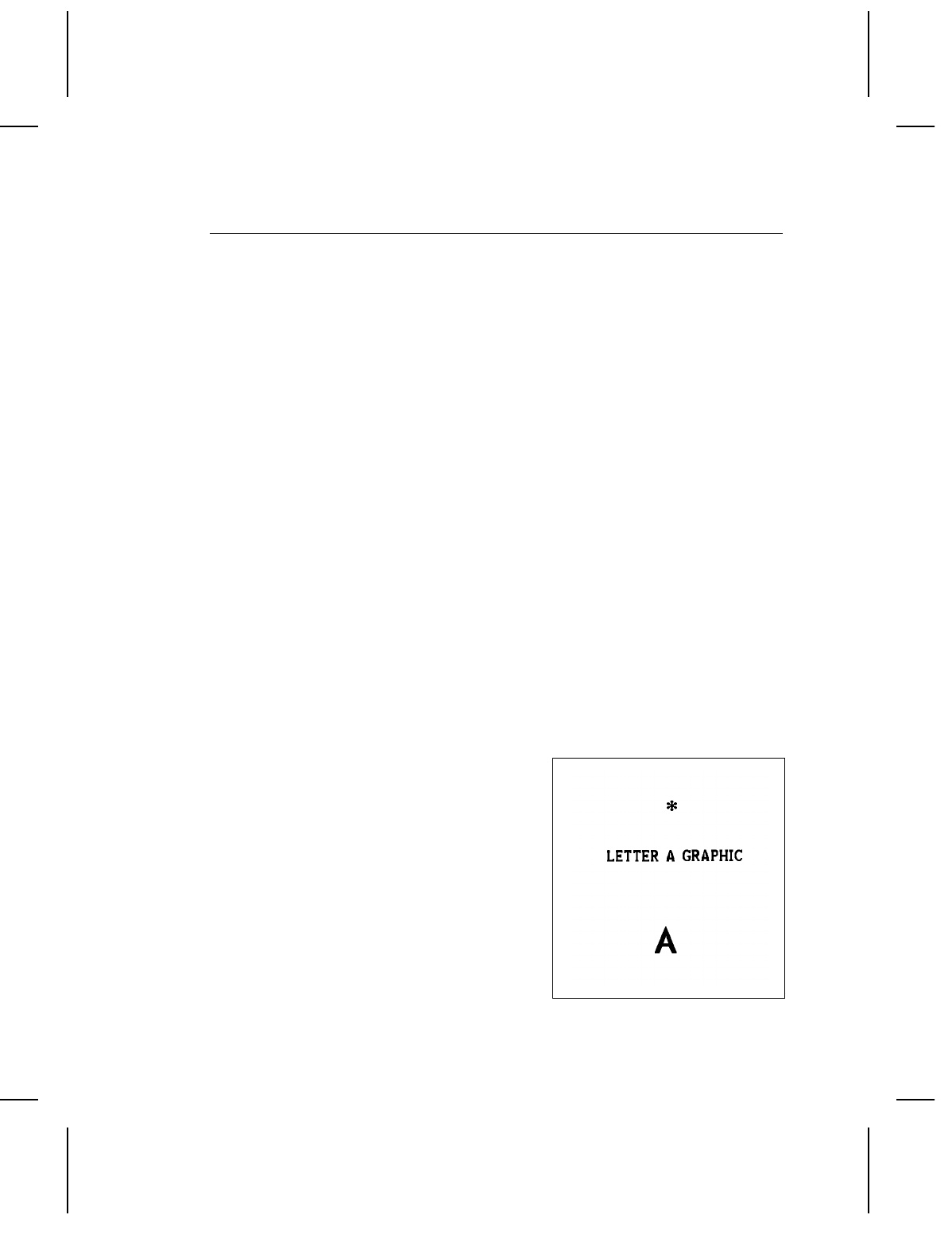
Compressed Graphic Data
This example shows the same graphic data stream in compressed
format.
Sample Compressed Graphic Data Stream
{G3,0,0,0,0 p
;3dHsHd p
;eGsGe p
;eHqHe p
;fGqGf p
;2fHoHf p
;gGoGg p
;gHmHg p
;3hGMGh p
;2iFMFi p
;3jEMEj p
;2kHgHk p
;lGgGl p
;2lHeHl p
;2mGeGm p
;3nGcGn p
;oFcFo p
;oGaGo p
;pFaFp p
;pFAFp p
;3qEAEq p
;2rDADr p
;3sCACs p
;2tBABt p
;3uCu p
;vAv p }
Sample Format Data Stream
{F3,0550,0507;GRAPHIC p
T0,I,0,400,100,1,1,0,0,B p
G3,200,200 p }
Sample Batch Data Stream
{B3,1,1,1,1,0,1;LETTER-A p
T0;LETTER A GRAPHIC p }
A-6 Sample Data Streams

CODE 128 INFORMATION B
The 128 bar code is divided into 3 character sets (Code A, Code
B, and Code C). Depending on the character set used, the same
bar pattern can be one of three characters. Table 1, at the end of
this appendix, lists the characters in each character set.
Code A contains upper case letters (A-Z), special
characters, and control characters. Code A
does not have lower case letters.
Code B contains upper and lower case alphanumeric
characters and special characters. Code B
does not have control characters.
Code C character set contains pairs of numbers. In
code C, each bar pattern represents a pair of
numbers, ranging from 00 to 99.
When the data contains at least four numbers in a row, 128
switches to code C, then prints one bar pattern for each pair of
numbers. This doubles the numeric data per inch.
Therefore, it may be better to pad numeric data with a zero if it
has an odd number of characters. The bar codes below show the
difference between an odd number of numeric characters and an
even number of numeric characters. Do this only if your system
can ignore leading zeros.
Bar Code 1
Data = 1234567
Bar Code 2
Data = 01234567
Code 128 Information B-1

Bar Code 2 is not as wide as Bar Code 1 because all of its
characters are printed with bar symbols from code C.
Only 6 of Bar Code 1’s characters are printed in code C. The
other character has to be printed in code B. Whenever 128
switches from one character set to another, it adds bar patterns
that tell a scanner to switch character sets. These extra bar
patterns cause wider bar codes.
Bar Code Width
The width of a Code 128 bar code is determined this way:
NIf there are four or more numbers in a row, an even number of
them print in code C.
NIf there are four or more numbers in a row with an odd quantity
(e.g., 7 numbers in a row), one of them prints in code B.
NAll other alphanumeric characters are printed in code B.
The printer determines which character set to use based on the
data. No external control of character set selection is required.
For a given quantity of data, the widest bar code will be the one
that switches character set most often. Suppose your data has
14 characters (8 numeric + 6 alphabetic).
The bar code for data arranged like this:
Bar code 1
Data = 1234ABC5678DEF
is wider than data
arranged like this:
Bar code 2
Data = 12345678ABCDEF
B-2 Code 128 Information

Here’s why bar code 1 is wider:
NThe 8 numbers in each example appear in groups of four or
more, and they appear in even-numbered quantities,
therefore, all 8 numbers will use code C.
NThe 6 alphabetic characters will use code B.
Look at the example again. This time, data is underlined when
the character set changes.
The bar code for data arranged like this:
Bar code 1
Data = 1234ABC5678DEF
is wider than data arranged
like this:
Bar code 2
Data = 12345678ABCDEF
This shows that bar code width varies depending on how data is
arranged. Separating numeric and alphabetic characters reduces
the number of character set changes. Fewer character set
changes reduce bar code width.
Code 128 Information B-3
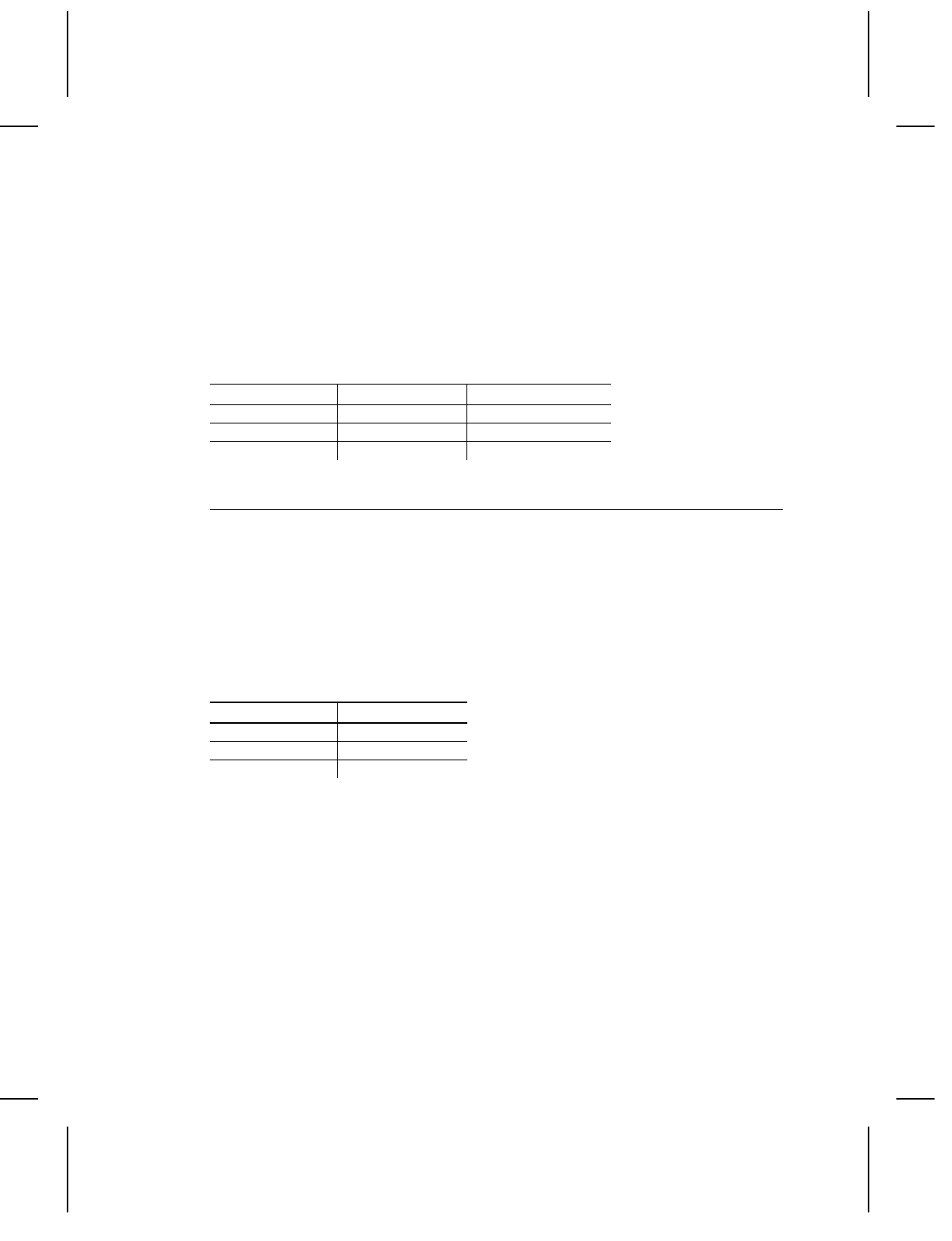
The table below shows the characters per inch for Code 128. The
table shows the values for numeric data, and for alphanumeric
data at each of the three densities available on the printer. The
characters per inch for your bar code will be somewhere between
these two values, depending on the mixture of numeric and
alphabetic characters. For a precise calculation of the width of
your bar code, refer to the specification for the Code 128 bar
code.
Density Numeric Data Alpha-numeric Data
1 17.48 8.74
2 11.66 5.83
3 8.74 4.37
Quiet Zone
When you estimate the area you’ll need for the bar code,
remember to add the length of the quiet zone. The quiet zone is
an area of white space required at the beginning and end of each
bar code. The minimum size of the quiet zone is 0.10, or 10
times the width of the narrowest bar code element, whichever is
greater. The tables below show the minimum size of the quiet
zone at each density. For wand scanning, the quiet zone should
be 0.25 to 0.35 inch.
Density Quiet Zone
10.10 inch
20.15 inch
30.20 inch
B-4 Code 128 Information

Function Codes
Code 128 has four function codes (f1-f4). These special
characters can be entered as:
Nfixed characters when defining a code 128 field (Format Entry)
Ndata when printing a batch (Data Entry).
Enter the special 128 function codes as follows:
to select this
Press these keys function code
F2 then 1 f1
F2 then 2 f2
F2 then 3 f3
F2 then 4 f4
The function code is displayed as F1, F2, F3, or F4.
Code 128 Information B-5

128 Bar Code Character Sets
Any of the following characters can be used in online
communication with the printer by sending the character’s
standard decimal value. To enter specific characters from the
keyboard, refer to "Using the Keyboard" in Chapter 4 of the
Operator’s Handbook.
Values listed on the chart are for reference only; they are not
decimal values.
Code Code Code Bar Pattern
ValueABCBSBSBS
0 S SP 00 212222
1 ! ! 01 222122
2 " " 02 222221
3 # # 03 121223
4 $ $ 04 121322
5 % % 05 131222
6 & & 06 122213
7 ’ ’ 07 122312
8 ( ( 08 132212
9 ) ) 09 221213
10 * * 10 221312
11 + + 11 231213
12 , , 12 112232
13 - - 13 122132
14 . . 14 122231
15 / / 15 113222
16 0 0 16 123122
17 1 1 17 123221
18 2 2 18 223211
19 3 3 19 221132
20 4 4 20 221231
21 5 5 21 213212
22 6 6 22 223112
B-6 Code 128 Information

Code Code Code Bar Pattern
ValueABCBSBSBS
23 7 7 23 312131
24 8 8 24 311222
25 9 9 25 321122
26 : : 26 321221
27 ; ; 27 312212
28 28 322112
29 = = 29 322211
30 30 212123
31 ? ? 31 212321
32 @ @ 32 232121
33 A A 33 111323
34 B B 34 131123
35 C C 35 131321
36 D D 36 112313
37 E E 37 132113
38 F F 38 132311
39 G G 39 211313
40 H H 40 231113
41 I I 41 231311
42 J J 42 112133
43 K K 43 112331
44 L L 44 132131
45 M M 45 113123
46 N N 46 113321
47 O O 47 133121
48 P P 48 313121
49 Q Q 49 211331
50 R R 50 231131
51 S S 51 213113
52 T T 52 213311
53 U U 53 213131
54 V V 54 311123
55 W W 55 311321
56 X X 56 331121
57 Y Y 57 312113
58 Z Z 58 312311
59 [ [ 59 332111
60 \ \ 60 314111
61 ] ] 61 221411
62 ^ ^ 62 431111
63 _ _ 63 111224
64 NUL ’ 64 11142
65 SOH a 65 121124
66 STX b 66 121421
Code 128 Information B-7

Code Code Code Bar Pattern
ValueABCBSBSBS
67 ETX c 67 141122
68 EOT d 68 141221
69 ENQ e 69 112214
70 ACK f 70 112412
71 BEL g 71 122114
72 BS h 72 122411
73 HT i 73 142112
74 LF j 74 142211
75 VT k 75 241211
76 FF l 76 221114
77 CR m 77 413111
78 SO n 78 241112
79 SI o 79 134111
80 DLE p 80 111242
81 DC1 q 81 121142
82 DC2 r 82 121241
83 DC3 s 83 114212
84 DC4 t 84 124112
85 NAK u 85 124211
86 SYN v 86 411212
87 ETB w 87 421112
88 CAN x 88 421211
89 EM y 89 212141
90 SUB z 90 214121
91 ESC { 91 412121
92 FS | 92 111143
93 GS } 93 111341
94 RS ~ 94 131141
95 US DEL 95 114113
96 FNC3 FNC3 96 114311
97 FNC2 FNC2 97 111113
98 SHIFT SHIFT 98 411311
99 CODE CCODE C99 113141
100 CODE BFNC4 CODE B 114131
101 FNC 4 CODE ACODE A 311141
102 FNC1 FNC1 FNC1 411131
BSBSBSB
STOP 2331112
B-8 Code 128 Information

Index
A
ASCII codes 5-6 - 5-7
B
bar code
densities 5-3 - 5-4
extensions 3-15
human readable characters 3-14
restrictions 3-5, 3-15
supported codes 5-3
bar code field record 3-12 - 3-13
example 3-14
bar code field syntax 3-14
bar code record syntax 3-12 - 3-13
batch
multiple batch per format 3-22
print data 3-21
sending data 3-6
using previously defined data 3-22
batch data 1-2, 3-19
batch data syntax 3-21
batch header record 3-19 - 3-20
example 3-21
batch header syntax 3-19 - 3-21
batch separator syntax 3-24
batch separators 3-24
baud rate 2-1
boxes, creating with lines 3-18
buffer, input 2-1
C
cable interface 2-5
character codes 5-6 - 5-7
characters,flow control 2-2
code 128
function codes 3-15
restrictions 3-15
code 128, function codes 5-6 - 5-7
coding chart, graphics 4-3
command characters3-4
commands 3-4
communication requirements 2-1
communication values, setting 2-3 - 2-4
Configuration Options menu 2-3 - 2-4
consecutive batches 3-22
creating data streams 3-1 - 3-2
D
data bits 2-1
data errors 3-3
data flow control 2-2
data stream
programming conventions3-4
data streams
creating 3-1
transmitting 3-1 - 3-2
data types 1-2
default settings 2-1
density, bar code 5-3 - 5-4
dot patterns 4-1 - 4-5
DTR 2-2
E
entering print data 3-21
error
messages 6-1
extended bar codes 3-15
F
flow control 2-1 - 2-2
font sizes 5-1 - 5-3
Index-1

Font, printable characters 5-8
format
ID numbers 3-5
using graphics 4-6
format data 1-2
format header record3-8
format syntax 3-8
function codes 5-6 - 5-7
function codes, code 128 3-15
G
graphic data record
example 4-5, 4-7
syntax checklist 4-7
graphic data syntax 4-5, 4-7
graphics
clearing the image buffer 4-8
coding chart 4-3
compressing the data stream 4-8
creating the image 4-1 - 4-3
data stream 4-3
order of transm ission 4-1
placing in a format 4-6
steps to printing 4-1
syntax 4-4 - 4-6
H
Host port configuration 2-3 - 2-4
human readable characters,bar
codes 3-14
I
input buffer 2-1
input characteristics 2-1
international pricing symbols 3-4
introduction 1-1
L
line
thickness 5-5
line field record 3-16 - 3-18
example 3-18
line field syntax 3-18
line record syntax 3-16 - 3-18
line width
9420/9440 5-5
9425 5-5
9445 5-5
9474 5-5
lines
creating boxes 3-18
examples 3-18
M
messages
diagnostic 6-2
error 6-1
startup 6-2
monetary symbols 3-4
multiple batches per format 3-22
O
offline formats 1-2
Online
Host port configuration 2-3 - 2-4
online bar codes
special restrictions 3-14
online formats 1-2
order of transmission 3-5
overlapping fields 3-5
P
parity 2-1
pricing symbols 3-4
Printable characters, font 5-8
programming conventions 3-4
R
Index-2

restrictions
bar codes 3-5, 3-15
RS-232 interface 2-5
S
sending batch data 3-6
sending data
order 3-5
setting communication values 2-3 - 2-4
special characters 5-6 - 5-7
special restrictions
online bar codes 3-14
stop bits 2-1
symbols 5-6 - 5-7
syntax
bar code field 3-12 - 3-14
batch data 3-21
batch header 3-19 - 3-21
batch separator 3-24
format 3-8
format header 3-9
graphic data 4-5, 4-7
graphics 4-4 - 4-6, 4-8
line field 3-16 - 3-18
text field 3-9 - 3-11
T
text field record 3-9 - 3-11
example 3-11
text field syntax 3-11
text fonts
character width 5-2
parallel character widths 5-3
sizes 5-1
text record syntax 3-9 - 3-11
transmission errors 3-3
transmitting data streams 3-1 - 3-2
types of data 1-2
U
using graphics 4-1, 4-3 - 4-6, 4-8
using previously defined data 3-22
X
Xon/Xoff 2-2
Index-3

Index-4