Paxton Access 313110 Long Range Reader User Manual INSTRUCTION Long range reader
Paxton Access Ltd Long Range Reader INSTRUCTION Long range reader
Manual
Ins-30060-US Long range reader
21/01/2008
What is Hands Free?
A long range reader can read Paxton hands free tokens up to a maximum of 5 yards. The system comprises of a
long range reader with an integral hands free interface and hands free tokens (keycard or keyfob). The system
operates by using the eld being transmitted by the reader to wake up the token which then communicates with
the interface.
Existing Switch2 or Net2 control units, can be used without modication. Standard Paxton tokens/keyfobs can
be used with this reader but at their normal read range (see table on back page)
Hands free tokens also include a standard proximity ID chip and can therefore be presented to any Paxton
LED indications
The unit has a single high intensity LED array that displays RED or GREEN indications.
Steady RED - Waiting for card ( IDLE state )
Flashing GREEN - Access Granted ( or held unlocked )
Flashing RED - User Access Denied
If an error condition exists ( ACU powered off, Cable break, etc) the LED will show a steady RED indication.
Layout
Technical Support
Technical help is available: Monday - Friday from 5am - 11pm PST / 8am - 2am EST
Saturday from 7am - 11am PST / 10am - 2pm EST
Documentation on all Paxton Access products can be found on our web site - http://www.paxton-access.com/
1 800 672 PAXT support@paxton.co.uk
12v
Red LED
Amber LED
Green LED
Data/D0
Net2 Control Unit
Clock/D1
Media Detect
0V
Entry
12v
Red LED
Amber LED
Green LED
Data/D0
Clock/D1
Media Detect
0V
Entry
Green LED
Exit/Entry
0V
12V
Net2Air Interface
Reader
Red 12v dc
Brown
Keypad 2 Reader 2
Orange
Green
Yellow
Blue
Mauve
Black/White
Brown
Yellow
Orange
+12V
0V
N.C.-
N.O.-
Com
N.C.-
N.O.-
Com
Alarm Output
0V
Contact
0V
Exit
0V
Tamper
PSU
RX
TX
Relay 1
Relay 2
Exit
Contact
Tamper
PSU
OK
5V
12V
Red
Brown
Orange
Green
Yellow
Blue
Mauve
Black/White
Brown
Yellow
Orange
Networkj
CAT5 Cable coding
White/Green
Green
White/Orange
Orange
1
2
3
4
Screen or spare cores
from network cable
Seriel number
241821
TestID: 012345678901
z-14401
3
24898 00000
4
PowerRelay 1Relay 2
Inputs
12Vdc
Power Supply
Not Connected
Not Connected
Not Connected
Reader 1 Keypad1
Caution: For 12V d.c readers only. For
connection of old 5v readers, refer to
instructions
12v
Red LED
Amber LED
Green LED
Data/D0
Net2 Control Unit
Clock/D1
Media Detect
0V
Entry
12v
Red LED
Amber LED
Green LED
Data/D0
Clock/D1
Media Detect
0V
Entry
Green LED
Exit/Entry
0V
12V
Net2Air Interface
Reader
Red 12v dc
Brown
Keypad 2 Reader 2
Orange
Green
Yellow
Blue
Mauve
Black/White
Brown
Yellow
Orange
+12V
0V
N.C.-
N.O.-
Com
N.C.-
N.O.-
Com
Alarm Output
0V
Contact
0V
Exit
0V
Tamper
PSU
RX
TX
Relay 1
Relay 2
Exit
Contact
Tamper
PSU
OK
5V
12V
Red
Brown
Orange
Green
Yellow
Blue
Mauve
Black/White
Brown
Yellow
Orange
Networkj
CAT5 Cable coding
White/Green
Green
White/Orange
Orange
1
2
3
4
Screen or spare cores
from network cable
Seriel number
241821
TestID: 012345678901
z-14401
3
24898 00000
4
PowerRelay 1Relay 2
Inputs
12Vdc
Power Supply
Not Connected
Not Connected
Not Connected
Reader 1 Keypad1
Caution: For 12V d.c readers only. For
connection of old 5v readers, refer to
instructions
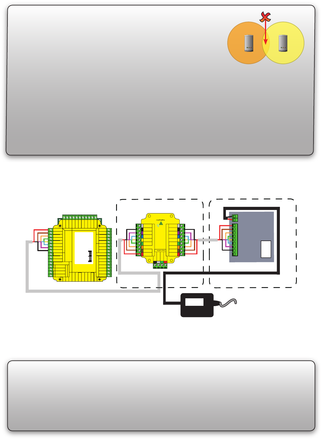
Wiring
It is important to run an appropriate power cable to the reader that is capable of carrying a current of 1A.
A data cable must be run from the control unit to the reader interface. The recommended cable for this is Belden
9540; a 10 core overall screened cable with a maximum cable length of 100 yards. Spare cores should be used
to double up on the power wires (Red/Black) to the interface.
The reader requires a higher current (up to 1A) than can be supplied by the ACU reader port and so an
independent 12V DC power feed must be provided. As per the wiring diagram, the spare outputs on the Paxton
2A boxed power supply can be used for this purpose.
Before you install
Read in, read out
When using in and out readers, users may be picked up by both readers as they move through the door which
will effect the reliability of any Roll Call or Antipassback application. Ensure that sufcient spacing is provided
between these readers for optimum range and reliability.
Positioning readers
For maximum read range the Hands Free reader eld should not be
overlapped by the eld from other interference sources at or around 125KHz.
These include Loop readers, non Paxton readers, etc.
Readers should not positioned so that their active elds overlap.
(see table on back page for typical hand free read ranges)
For optimum keyfob battery life please choose your reader location carefully to avoid placing it within hands free
range of work stations, rest or smoking areas.
NOTE: Each long range reader requires a dedicated ACU reader port.
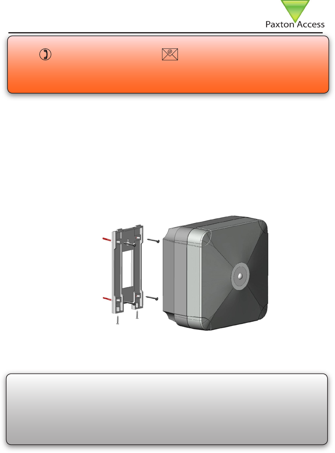
To achieve the maximum range for the device, the interface PCB has been mounted upside down to position the
internal aerial away from other reader components.
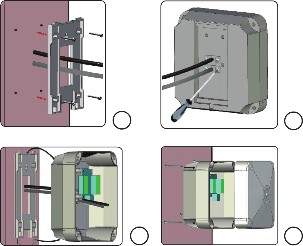
Fitting
1
2
3
4
Determine the position of the reader and mark and drill holes for the xing screws and cable access.
Fix the mounting plate to the post with the locating hooks at the top. (Fig 1)
Feed the cables for power and data thorough the mounting plate and into the rear section of the reader leaving
enough slack to allow easy connection to the circuit boards later in the installation.
Tighten the weatherproof cable glands at the rear of the reader. (Fig 2)
Hang the rear reader section on the mounting plate and secure with two screws. (Fig 3)
Complete the wiring of the reader as shown in this instruction.
Join the front section to the rear section with the Allen screws provided. (Fig 4)
NOTE: It may be necessary to briey remove the reader from its mounting plate if access to the Allen screws is
limited by the post or wall.
The long range reader consists of a reader module mounted inside the front half of the housing and a hands free
interface mounted inside the rear half. An interconnect cable is supplied that connects the two sections together.
Two 5 yard cables for data and power are provided. These enter the module at the rear through two compression
glands. If longer cables are required, refer to the previous section for further details.
12
34
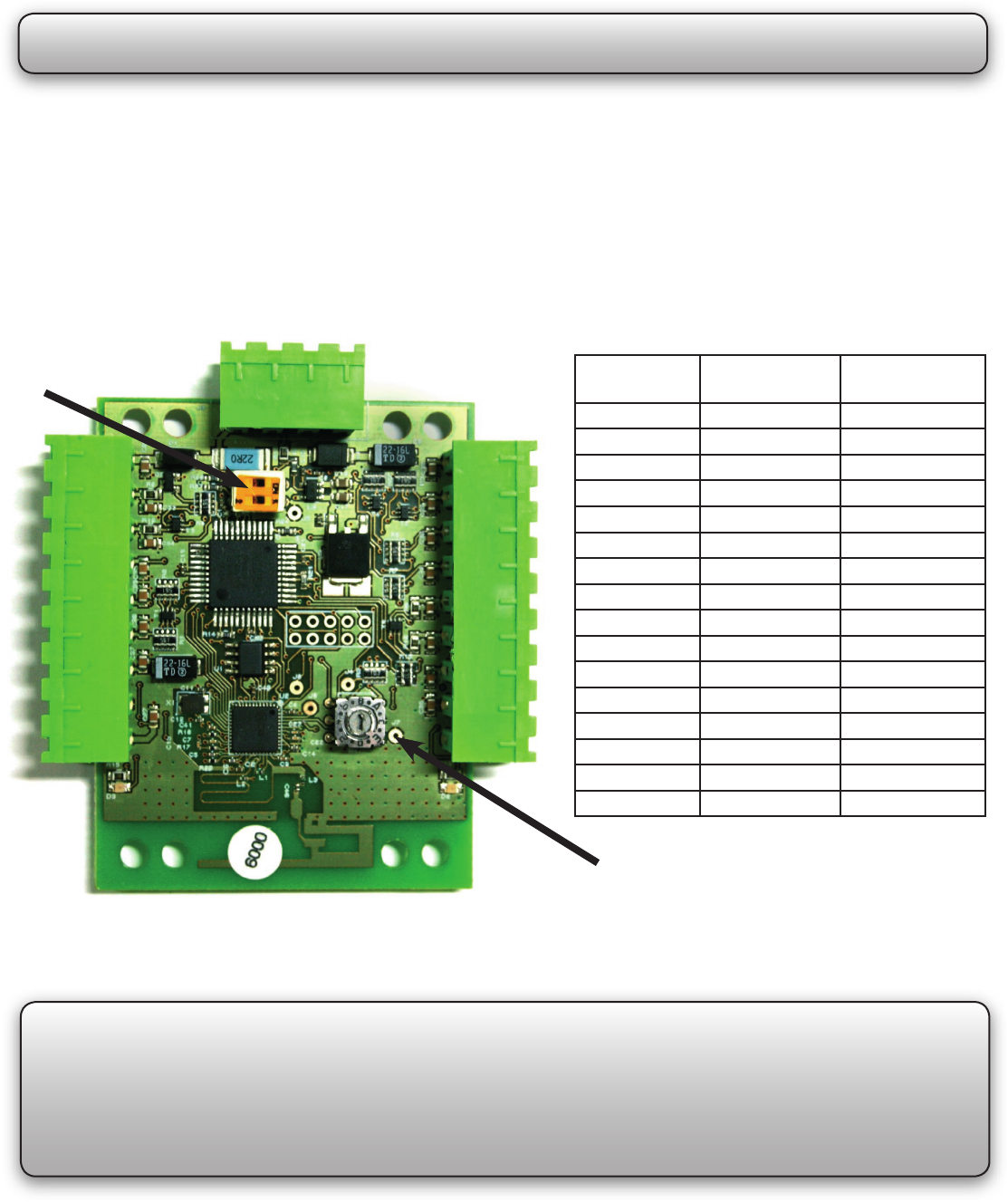
Changing frequency channel
If you are experiencing problems with the range or reliability this may be due to poor reader positioning, adjacent
interfering 125KHz or 2.4 GHz equipment, e.g. an adjacent wireless PC network. Please refer to the ‘Before you
install’ information regarding unit locations. If you are still unable to improve the system performance then you
may try an alternative 2.4 GHz channel using Switch 1. Power cycle the unit after any changes.
The system has 16 different channels available. The unit is set to channel 4 as this frequency is normally clear of
other device transmissions. This can be changed using a small at blade screwdriver. Take care not to contact the
circuit board with the screwdriver blade as this may damage components.
0 2.405 11
1 2.41 12
2 2.415 13
3 2.42 14
4 2.425 15
5 2.43 16
6 2.435 17
7 2.44 18
8 2.445 19
9 2.45 20
A 2.455 21
B 2.46 22
C 2.465 23
D 2.47 24
E 2.475 25
F 2.48 26
SW1. Rotate the switch to select an
alternate channel.
All hands free tokens automatically congure themselves to use
the new channel. No conguration of the token is required.
GHz
Switch
position
The switch should initially be set to the
default position ‘4’
IEEE 802.15.4
channel
Keycard conguration
The switch SW2 is used to select which button on a Keycard is active for this interface.
Please refer to instruction sheet ins-30037-US for switch conguration supplied with the keycard.
SW2
The unit must be power cycled if the switch position is changed to recongure the settings.
Conguration

11V DC 14V DC
1 A
119 kHz 140 kHz
2.405 GHz 2.480 GHz
600 µs
Belden 9540
100 yds
3 inch 1
1/2 inch 1/2 inch
16 ft
6 ft
P200 8 ft
P75 5 ft
P50 4 ft
P38 3 ft
- 20 °C + 55 °C
8
1/2 inch 8
1/2 inch 4
3/4 inch
Specications
Voltage
Clock and data bit period
Carrier frequency
Operating temperature
Electrical
Environment
Dimensions
Min Max
Width Height Depth
Current
P200E metal mount
Cable type for extensions
Cable length between ACU and reader
Read range with Hands Free token
System Specication
Waterproof
Additional power supply required
Outdoor Use
Button conrmation input Yes
Yes
Long range reader
Min
Min
Min
Max
Max
Max
Token Keyfob Watchprox
Read Range
Long range reader
Using an entry conrmation button
Where two door readers may pick up the same hands free token, a push to make button can be used to conrm
an entry request for the specic door. Where tted, the button LED will ash for 5 seconds after the hands free
token has been recognised and must be pressed to unlock the door.
To enable the use of an entry conrmation button do the following steps:
1. Power down the interface board
2. Power up the interface board
3. Press and hold the entry conrmation button for a minumum of 3 seconds within 60 seconds of power up.
To disable the use of the button repeat the above process.
FCC Compliance
This device complies with Part 15 of the FCC Rules. Operation is subject to the following two conditions: (1) this
device may not cause harmful interference, and (2) this device must accept any interference received, including
interference that may cause undesired operation.
Changes or modications not expressly approved by the party responsible for compliance
could void the user’s authority to operate the equipment.