Paxton Access 345220 PROXIMITY P50M HID READER User Manual
Paxton Access Ltd PROXIMITY P50M HID READER
User Manual
PAGE 1
Ins-40158-US PROXIMITY P50M HIDTM reader - UL
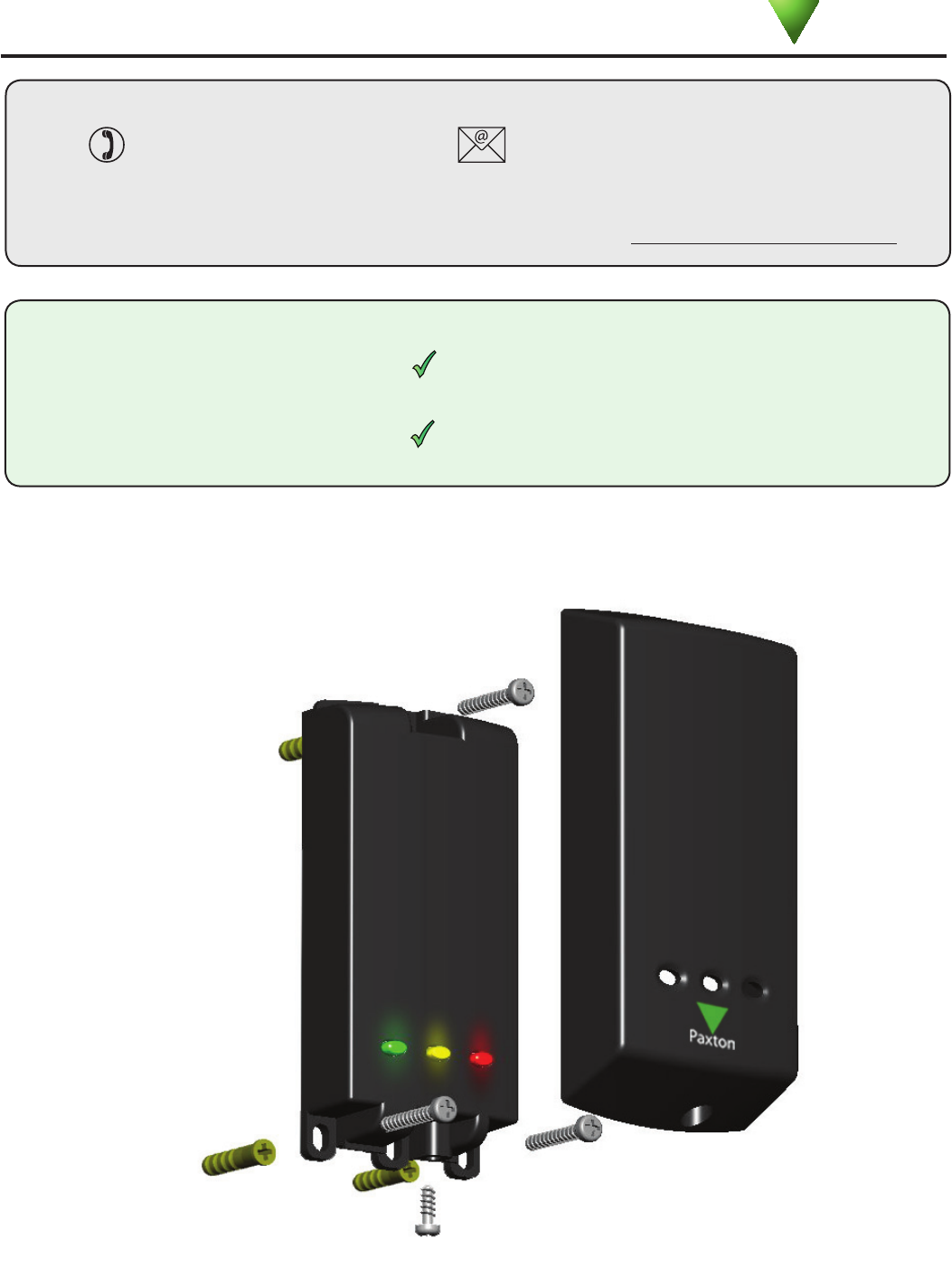
Mounting
Technical Support
Technical help is available: Monday - Friday from 02:00 AM - 8:00 PM (EST)
1.800.672.7298 support@paxton-access.com
Documentation on all Paxton products can be found on our web site - http://www.paxton-access.com/
Paxton
Readers mounted together
between readers
12 inches
Suitability
Security sensitive doors
Wet environments
06/08/2011
PAGE 2
Cable extensions
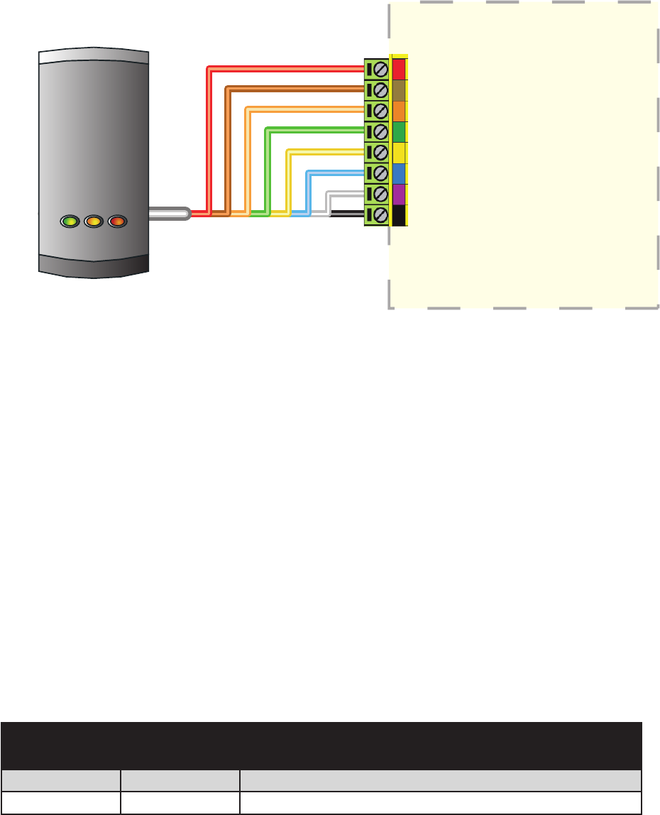
Wiring
Wiring methods shall be in accordance with the National Electrical Code (ANSI/NFPA70), local codes,
and the authorities having jurisdiction.
Use Max length Type
Reader 500 feet Belden 9540, 9538, Alpha 1298C (22AWG) or equivalent
Cable Specication
Token type and conguration
The reader will recognise 125kHz proximity tokens in HIDTM format to produce a Wiegand output (26 to 50 bit) or
EM4100 tokens to produce an ABA Track2 Clock and Data output.
The conguration of the reader is done automatically when the reader detects the rst token presented. It will scan
the token and match the reader to the format discovered.
The reader defaults to HIDTM settings after 3 minutes of the initial powering up if no EM4100 token has been
presented. If you require EM4100 operation, power cycle the reader and present an EM4100 token within 3 minutes.
Once in HIDTM or EM4100 mode, the reader will remain in that format.
Connection to a control
unit reader port
+12V DC
Red LED
Amber LED
Green LED
Clock/data1
Data/data0
Not required
0V

PAGE 3
Unit installation / test
Following the completed installation of this equipment, no further maintenance or testing is required.
It is advisable to ensure that any third party backup power supplies or recovery procedures are checked regularly
to ensure that the operation of the Paxton system is not compromised.
Maintenance
Part Description
345-220-US PROXIMITY P50M HIDTM reader
Fitting Kit (5) Cable clips
(3) No. 6 x 3/4 woodscrew - zinc
(3) Wall plugs 22mm
(1) 8mm x 3mm pan head self tapping screw - zinc
(2) Backbox screws
Parts List
FCC Compliance
This device complies with Part 15 of the FCC Rules. Operation is subject to the following two conditions:
(1) this device may not cause harmful interference, and (2) this device must accept any interference received,
including interference that may cause undesired operation. Changes or modications not expressly approved by
the party responsible for compliance could void the user's authority to operate the equipment.
When choosing a location for the reader, ensure that it is at least 12 inches from other readers. This will include
readers mounted on the other side of the same wall as the radio signal will cause interference and reduce the read
range. Mounting the reader on metal surfaces will reduce the read range.
Standard Unit - Drill a hole in the surface for the rear data cable. Secure the unit to the surface with three screws
as per tting diagram on page 1. Suitable screws and xings are provided for installing the unit to a wall. Ensure
the data cable has free access at the rear.
A choice of black and white covers are also provided. Hook the required cover over the top of the reader, press
home at the bottom and secure with the single xing screw.
The reader will beep and all the LED's should display after powering on the control unit. Presenting a user card to
the reader will cause the LED's to briey change to a single Green or Red LED.
Check the following FAQs section for assistance if any problems are encountered.

PAGE 4
1 - Readers/Keypads not working.
Q- Software settings - Conrm that the settings of the reader or keypad are correct.
Q- Connections - Check the wiring and integrity of the connectors. If possible, test this reader on the other port.
Q- Extended cable - Belden 9538/9540 should be used up to a maximum of 500 feet. Twisted pair alarm cable should
Q not be used. To conrm that an extended reader cable is not at fault, wire the reader directly to the port.
Q- Supply voltage - Conrm that the voltage is within specication. (see table)
Q- User token - Conrm that the user token used for testing is OK by presenting it to a known working reader.
Q- Interference - Conrm whether the reader works when tested 'in hand' and not mounted on the wall.
Q PROXIMITY readers should not be mounted back to back or close to other RF devices.
2 - Readers / Keypads - Extending cable.
QOnly Belden CR9538 / 9540 or a UL equivalent can be used for cable extensions. The maximum run is 500 feet.
3 - Net2 - Using a door reader as a desktop reader.
QIt is possible to congure a door reader to operate as a desktop reader:
Q1 - Select the doors menu in the left hand Net2 pane.
Q2 - Click on the door you wish to change the reader to act as a desktop reader.
Q3 - Under the relevant reader tab, change the reader operating mode to 'Desktop Reader'.
Q4 - The PC displays 'Would you like to accept desktop reader events from this reader at the PC?' ; click 'Yes'
Q Now when you present a blank or existing token to that reader it will allow you to add this new token or edit
Q the existing one.
NOTE:QRemember to return the operating mode to the original setting once the cards have been read
Q or users will not be able to gain access through the reader.
Q KP Reader - Ensure that Keypad type is set to 'None', otherwise the Desktop reader option will not be available.
4 - Net2. What to do if a user has no access - Check the reader LED's when a card is shown.
Q- No LED's - the reader has no power.
Q- No change in display - try the card on a known working reader. If there is still no response, replace the card.
Q- Green LED ashing when a card is presented; check relay 1 LED to check for activity and also the lock wiring.
Q- Red LED is ashing when a card is presented; check the validity of the user at the PC.
Q Check user's access level and ensure they should have access by clicking on Current Validity.
Q Check the 'Valid Until' date and conrm this has not expired.
Q- Reinstate the ACU from the doors screen. Select the ACU's you wish to reinstate and then click OK.
Here is the list of topics about this product that receive the most technical support inquiries.
We list them here to help you speed up the installation and trouble shooting process.
Technical Help
12V DC
130 mA
115 kHz 135 kHz
-35 °C ( -31 °F ) +66 °C ( + 151 °F )
IPX7
10 feet
1 3/4 inch 4 inch 3/4 inch
3 inch 2 inch Not Compatible
Voltage
Carrier frequency
Specications
Operating temperatures - all items
Electrical
Environment
Dimensions
Min Max
Width Height Depth
Current
Cable length
Read Range Token Keyfob Hands Free Token
Waterproof
Min Max
Outdoor Use