Paxton Access 654943 Net2 nano 1 door access control unit User Manual INSTRUCTION Net2 nano control unit
Paxton Access Ltd Net2 nano 1 door access control unit INSTRUCTION Net2 nano control unit
User Manual
r
e
daeR
:n
o
i
t
u
a
Cy
l
n
o
s
r
e
d
a
erC
D
V2
1
r
o
F
12V
Red LED
Amber LED
Green LED
Data/D0
Clock/D1
Media Detect
0V
Entry
12V
12V Lock
0V
0V
N.C.
N.O.
COM
Alarm
12V
Green LED
Exit
0V
Contact
0V
0V
Tamper
PSU
0V
n
o
t
t
u
B
t
i
x
Ey
al
e
Rk
co
L
s
t
u
p
t
u
O
s
t
u
p
n
I
r
e
w
o
P
t
c
atn
oC
repmaT/USP
Net2 nano
http://paxton.info/107
123456
0889
12345126
Ins-30075-US Net2 nano control unit
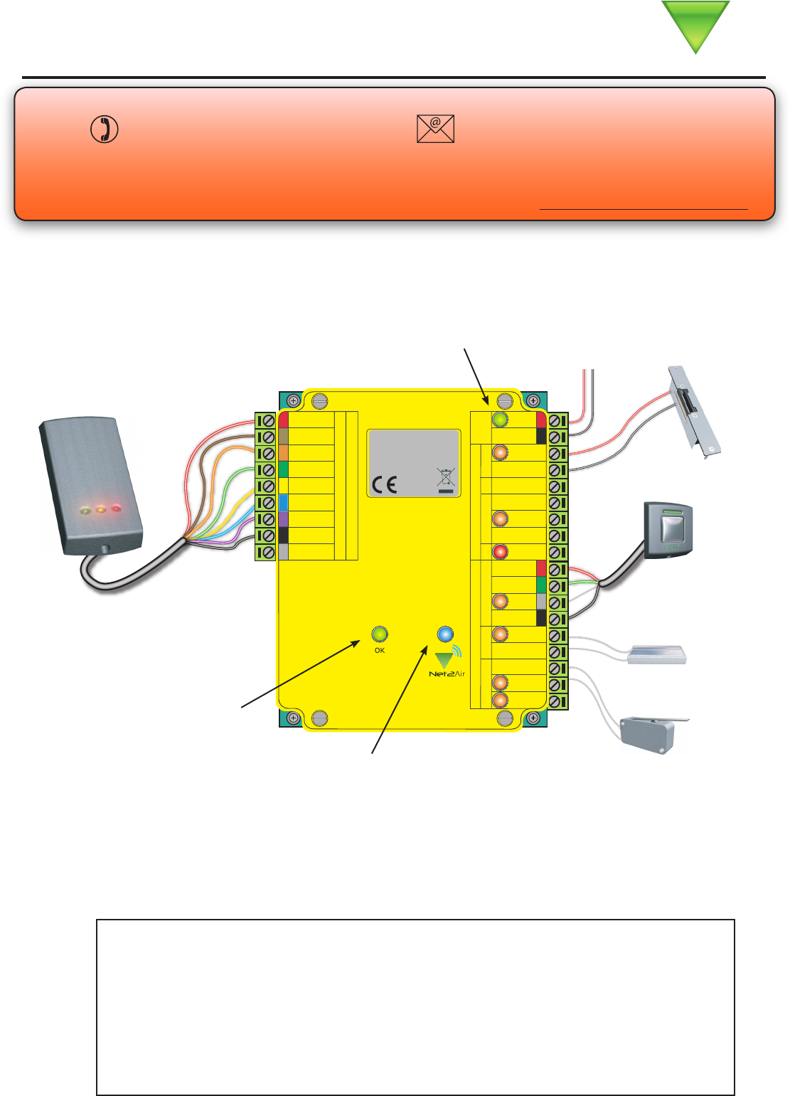
Exit button
(push to make)
Reader/keypad
Tamper switch
(optional)
Door contact switch
(held closed by door)
Paxton Access
05/03/2009
Technical Support
Technical help is available: Monday - Friday from 12:00 AM - 5:00 PM (PST)
Saturday from 1:00 AM - 5:00 AM (PST)
1.800.672.PAXT support@paxton.co.uk
To 12V DC
power supply
This is the heartbeat of the
system and should pulse
regularly. This indicates that
the processor is functioning.
Net2Air wireless activity (Tx/Rx) - Blue
12V (Green) - Power LED.
Lock (Orange) - The 12V lock output is energised.
Relay (Orange) - The relay is energised - (NO/COM contacts are closed).
Alarm (Red) - 12V Alarm output is active.
Exit (Orange) - The exit button contacts are closed.
Contact (Orange) - The door contacts are closed.
Tamper (Orange) - The tamper contacts are closed.
PSU (Orange) - The PSU contacts are closed.
Net2Air (Blue) - Net2Air interface Tx/Rx activity.
OK (Green ash) - The internal software is running.
LED indications
Documentation on all Paxton Access products can be found on our web site - http://www.paxton-access.com/
Net2 nano is a wireless based 1 door access control unit. It is recommended that a Net2Air
site surveyor is used to determine the best position for the bridge and units.
Diagnostic LEDs
This unit requires a Net2Air bridge (USB or Ethernet) to communicate
with the controlling PC running Net2 v4.14 or later software.
*
not connected
*
Lock release
NOTE: A new unit requires approximately 30 seconds after initial power up to self congure.
During this time the OK LED will not be ashing.
The unit will not operate until this operation has completed.
Control unit installation
Wire the components to the Access Control Unit (ACU) as shown on the rst page. This will include:
- Reader/Keypad
- Electric Lock
- Power supply
- Any other optional components
Press the exit button or in the absence of an exit button short the 0V and exit terminals to test the relay function.
The Relay LED will come on and the lock should release.
The access control unit connects to the Net2 software running on the PC using Paxton Access’ Net2Air proprietary
wireless technology. The Net2Air USB bridge enables communication from the Net2 software to the Paxton Access
nano family of products.
Radio signals do not always behave as you might expect. For example, a mobile phone that displays a full signal
on one part of the site will lose signal completely only a few metres away. These problems can be addressed by
using the Net2 site surveyor kit. (690-200-US)
See also: XAN1095 - Net2 nano - How does it work? < http://paxton.info/974 >
X AN1096 - How to plan a Net2 nano installation < http://paxton.info/975 >
X Ins-30096-US - Net2Air site surveyor < http://paxton.info/1193 >
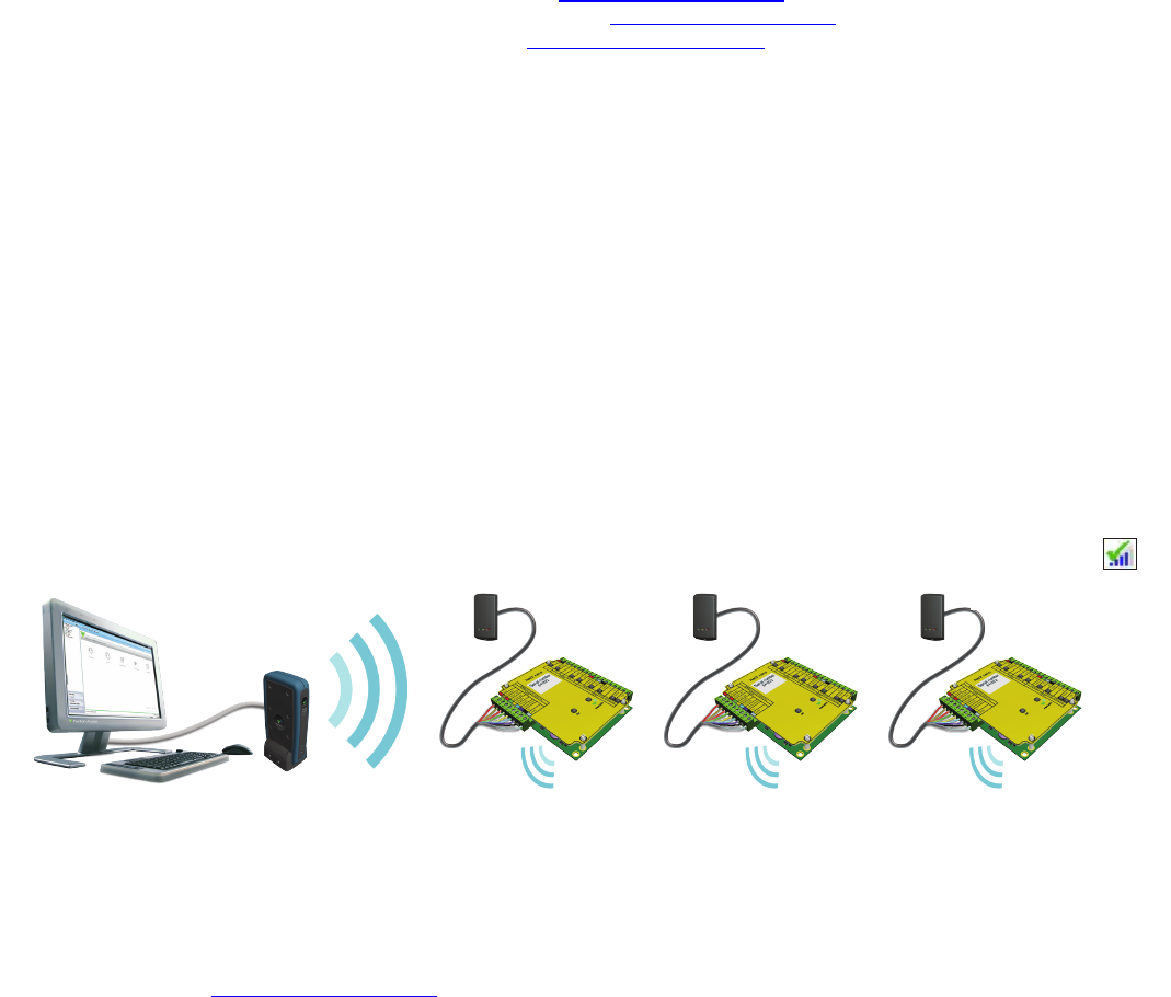
Data transfer with wireless technology requires far more control and error checking than with a hard wired data
line connection. Net2 classic runs with a server that originates and controls all the communications on the data
line. This would not be efcient in a wireless environment.
We therefore give the Nano controller the active role. Each Nano is always active and transmits data bursts
(including a regular Heartbeat) every few seconds. The Net2 server then acts upon these requests for service.
The PC requires at least one Net2Air bridge to communicate with a Nano. This can be a local Net2Air USB bridge
(only one per system) and/or multiple Net2Air Ethernet bridge units connected to the PC via a TCP/IP connection.
Net2 nano PC / server operation
Net2Air wireless communication
PC Installation
The current specication for compatible PC hardware, network and operating systems is available on our website
at the following link: http://paxton.info/720
There is NO Net2 nano detection function. It is recognised that there could be security issues if the wireless
units were detectable from outside the site. During installation, a nano unit makes a permanent one-to-one link
with a Net2Air bridge and is then enrolled into the Net2 database.
The wireless Net2 nano is fully compatible with the hard wired Net2 range but there are several important
differences that need to be understood before installing the equipment. The most important of these being the
location of the units and their bridge components.
These principles are therefore explained rst before we move on to the Net2 nano unit itself.
The readers default indication has all the LEDs on. Access granted is denoted with a single ashing Green LED,
Access Denied is a single ashing Red LED.
NOTE: A Net2 nano ACU or a Hands free interface cannot be installed in a Metal cabinet as this would block
the RF signal used for the Net2Air wireless technology.
Reader
Control unit
Net2 Server
An entry is then made on the Doors screen and a special icon is used to denote the wireless connection.
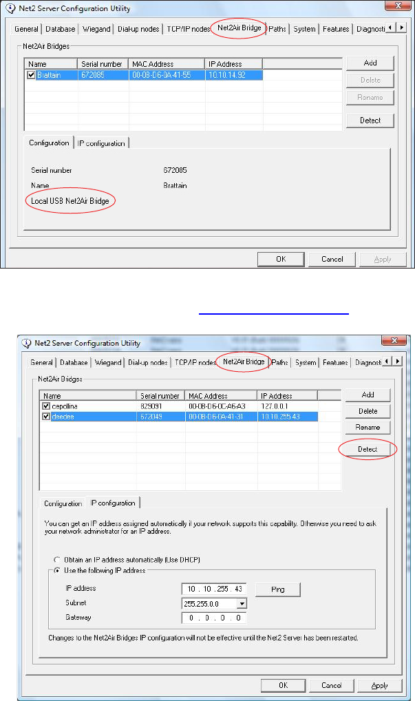
Once all the ACUs have been tested and the Net2 nano powered up, the Net2Air bridges need to be congured.
A USB Net2Air bridge will be registered by the Net2 software automatically. This displays in the Net2 Server
Conguration Utility/Net2Air bridge as a xed IP entry.
Software installation
To register an Ethernet Net2Air bridge, click on Detect and setup the IP addresses as required.
See also:X Ins-30085-US Net2Air Ethernet bridge < http://paxton.info/1192 >
Radio frequency
If you are experiencing problems with the range or reliability this may be due to poor nano / bridge positioning.
The unit is set to channel 11 (2.405 GHz) as this frequency is normally clear of other device transmissions.
Technical support can advise if you are concerned about interference from adjacent radio based (WiFi) equipment.
This product is not suitable for retail sale. All warranties are invalid if this product is not installed by a competent person.
A Nano must rst bind to a Net2Air bridge before it will enrol itself onto the Net2 system. The term ‘bind’ is used
to denote the xed relationship between a Nano and its bridge.
Create a user record in the database and assign a Net2 token to the user. If you are not using PROXIMITY tokens
you should still create the user record and assign a token number (Not a PIN) of your choice. These records can
be deleted after the installation is complete.
Connect a PROXIMITY reader to the Nano and then present the same user token previously assigned. (If you are
enrolling a Keypad only unit, enter the token number on the keypad followed by * ) The Nano will then transmit
this token number and will be looking for a response from a bridge.
If more than one bridge replies, the Nano checks the signal strength and selects the strongest bridge to
communicate with. The Net2 software conrms that this token number is in the database and if so registers this
Net2 nano/bridge as a permanent binding.
In future, if this bridge connection should fail, the Nano will NOT automatically select another bridge. You must
click Detect on the doors screen to call all the Nanos currently enrolled on the database. They will then establish
new links with the available bridges and each one will bind with the strongest signal.
Enrolling a Net2 nano
Software Conguration
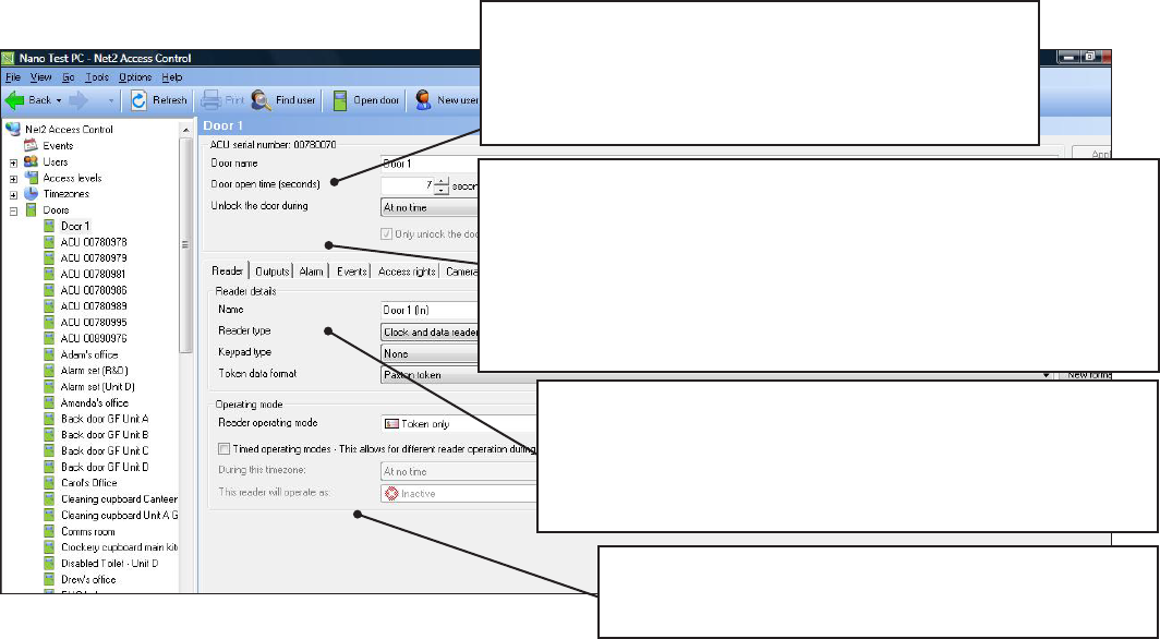
Reader: Settings for the Reader and Keypad.
Outputs: Lock, Relay, Alarm. - Selects these outputs to be
used by the Lock, Bell or Alarm functions.
Alarm: Congures the settings for the different alarm types.
Codes: Valid keypad codes can be viewed, added and removed
(This tab is only displayed when a keypad is tted)
Events: Shows the events for this control unit only.
Access Rights: Lists users who have access through this door.
Name: Each reader can be named individually if required.
Reader type: Set the reader type, if applicable.
Keypad type: Set the keypad type, if applicable.
Token data format: Select the type of cards being used
on the system. (New formats can be created).
Reader operating mode: Set the operating mode.
Timed operating modes: A different operating
mode can be congured within a time window.
Door name: Name the ACU.
Door open time: Set the door open time.
Unlock the Door during: Permanently unlocks the
door while this time zone is active. - Should be set
to ‘At No Time’ for normal user operation.
Delete / Reset the Net2 nano
The Nano controller holds the address information for the bridge that it has bound with. It will therefore never
communicate with any other bridge. This can cause problems if the unit is to be used in another location.
1. If the unit is in full communication with the Net2 system you can Delete the unit on the Doors screen and
remove it from the database. This will also clear the bridge information from the Nano and return it to its factory
settings. If a valid card is presented while it is still in range of the bridge, it will rebind.
2. If the unit is not in communication with its bridge, it can be given a hardware reset by linking Orange/Mauve
on the reader port and power cycle the unit. This will clear its bridge address information.
This device complies with Part 15 of the FCC Rules. Operation is subject to the following two conditions:
(1) this device may not cause harmful interference, and (2) this device must accept any interference received, including interference that
may cause undesired operation. Changes or modications not expressly approved by the party responsible for compliance could void the
user’s authority to operate the equipment.
FCC Compliance
This equipment must not be co-located with any other transmitter and must be used at a distance in excess of 20cm to the user.
The party that incorporates this equipment into another host device is responsible for verication of the emissions produced by the
nal product and must adhere to the limits specied in FCC Part 15.
Furthermore, a label must be applied to the exterior of the nal product referring to this enclosed module, which states : “Contains
Transmitter Module FCC ID: USE654943” or “Contains FCC ID: USE654943”.

1 - ACU fails to enrol onto the PC (WIRELESS PROBLEMS)
QThe Net2 Nano must be in range of a Net2Air bridge. This can be checked with a Site Surveyor. Detailed advice
Qcan be found on the website as follows:-
QXAN1095 - Net2 nano - How does it work? < http://paxton.info/974 >
QXAN1096 - How to plan a Net2 nano installation < http://paxton.info/975 >
QXIns-30096-US - Net2Air site surveyor < http://paxton.info/1193 >
2 - Readers/Keypads not working
Q- Software settings - Conrm that the settings of the reader or keypad are correct.
Q- Connections - Check the wiring and integrity of the connectors. If possible, test this reader on the other unit.
Q- Cable - Belden 9540 should be used to extend the reader cable (Max 100 yds). Twisted pair alarm cable should
Q not be used. To conrm that an extended reader cable is not at fault, wire the reader direct into the reader port.
Q- Supply voltage - conrm that the reader has sufcient voltage.
Q- User token - Conrm that the user token used for testing is OK by presenting it to a known working reader.
Q- Interference - Conrm whether the reader works when tested ‘in hand’ and not mounted on the wall. Ensure
Q that readers are not mounted back to back or there is no interference from other local RF devices.
3 - Why are some of the Net2 features (e.g. Fire alarm integration) not available on Net2 nano?
QWireless communication is not suitable for saftey critical applications.
4 - Net2Air - What does this mean?
QNet2Air is a term used to describe the wireless communication protocol used by Paxton Access products in much
Qthe same way as Bluetooth. The Net2Air protocol is not open, only Paxton Access products can use this technology.
QThe Net2Air protocol is based on the standard known as IEEE 802.15.4. It operates at 2.4GHz and can co-exist
Qwith wireless LAN networks and other devices using this frequency such as DECT phones. All Paxton Access
Qproducts employ AES128 encryption technology to ensure that all communication remains secure.
Here is the list of topics about this product that receive the most technical support inquiries.
We list them here to help you speed up the installation and trouble shooting process.
1 10,000
1 10,000
1 250
1 64
1 sec 99,999 sec
1 50
1 1
1 1
1 2
1 2
1 10
1 50
30 yds Typical 10 yds
60 days
6,000
11V DC 14.5V DC
120 mA
24V DC
2 A
1.1 A
1 A
500 mA
2.405 GHz
0°C (32°F) 55°C (131°F)
4 1/8 in 3 1/4 in 5/8 in
7 in 7 in 1 5/8 in
Voltage
Relay switchable current
Relay switchable voltage
Operating temperature - Battery limits
Electrical
Environment
Dimensions
PCB Current (depending on activity)
Features
Waterproof
Min
Width Height
Max
Min Max
Depth
Min Max
Number of PINS
Access Levels
Time Zones
Alarm output current
Maximum door open time
Doors per ACU
Reader ports per ACU
Readers per port
Keypads per port
ACUs per Net2Air bridge
Data retention after total power loss
Events stored in ACU with no server connection
Number of Cards
Number of Codes
Specications
No
Reader port output current
Control Unit
Plastic Housing
Net2Air bridge (data lines) per system
Net2Air wireless range to ACU
Dedicated lock output current
Carrier frequency