Paxton Access 746284 Easyprox nano User Manual INSTRUCTION Easyprox nano
Paxton Access Ltd Easyprox nano INSTRUCTION Easyprox nano
User Manual
Page 1
09/07/2009
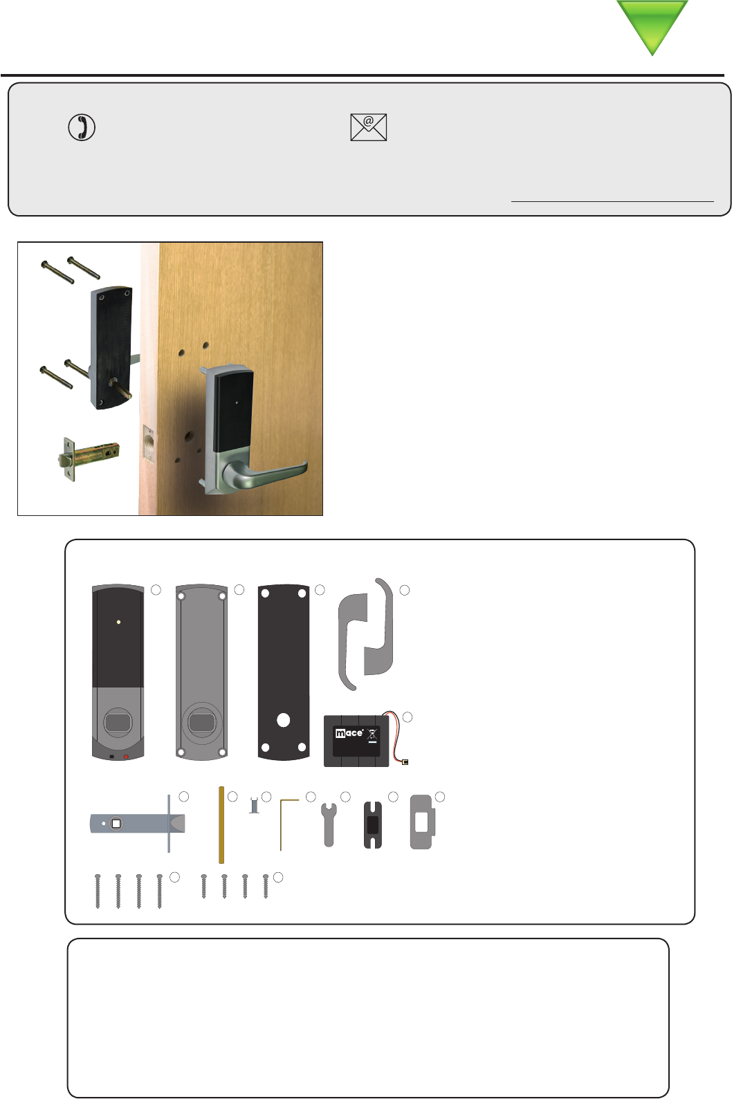
Parts list
Tools List
Power Drill
Drill bits 3/8”, 1”.
Philips screwdriver
Hacksaw for cutting bolts
Hammer / Mallet
Chisel 1 inch
Stanley knife
Adhesive tape
Pencil
Tape measure
8mm spanner (supplied)
2mm Allen key (supplied)
1) Front Lock Assembly
2) Rear Lock Assembly
3) Rubber Escutcheon x2
4) Left and Right Handles
5) Battery Pack
6) Tubular Mortice Lock
7) Square Drive Bar
8) 8 mm Conversion Sleeve
9) 2 mm Allen Key
10) 8 mm Spanner
11) Strike Plate Backbox
12) Strike Plate
13) Long Mounting Screws x4
14) Short Mounting Screws x4
This unit is for Indoor use only.
Technical Support
Technical help is available: Monday - Friday from 12:00 AM - 5:00 PM (PST)
Saturday from 1:00 AM - 5:00 AM (PST)
1.800.672.PAXT support@paxton-access.com
Ins-30107-US Easyprox nano
Documentation on all Paxton Access products can be found on our web site - http://www.paxton-access.com/
This access control unit uses wireless communication.
It is recommended that a Net2Air site surveyor is used to
determine the best position for the Net2Air bridge and Nano
control units.
This unit requires a Net2Air bridge (USB or Ethernet) to
communicate with the controlling PC running Net2 v4.14 or
later software.
ONLY
Paxton Access
4HIS BATTERY PACK IS TO BE REPLACED
WITH 0AXTON !CCESS PART NUMBER
Paxton Access
4HISBATTERYPACKISTOBE
REPLACEDWITH0AXTON!CCESS
PARTNUMBER 746-003ONLY
6
4HISBATTERYPACKISTOBE
REPLACEDWITH0AXTON!CCESS
PARTNUMBER ***-*** ONLY
6
Paxton Access
Page 2
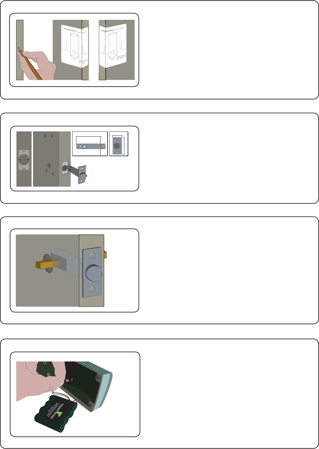
Decide on the lock height and mark this on the door.
Fold the template along one dotted line and tape it to
the door with the ‘Centreline of Latch’ at the required
height. Mark the 4 x 3/8”and 1 x 1” holes. Remove the
template, fold along the other dotted line and apply it
to the other side of the door at the same height. Mark
the holes as before.
Remove the access plate at the rear of the unit by
removing the top standoff screws. Push the battery
pack lead onto the white power plug.
Fit the battery pack into the unit and replace and
secure the access plate.
Installing the hardware
Step 1 - Marking out
Step 2 - Drilling
Step 3 - Fitting the latch
Step 4 - Fitting the battery pack
Drill a 1” hole in the door edge at least 3” deep to
accept the latch.
Drill the 4 x 3/8” holes for the mounting screws and
a 1” hole for the square bar. To ensure accuracy
you should drill these holes from both sides of the
door towards the centre. This also avoids the risk of
damaging the door face when the drill breaks through.
Slide in the latch and draw around the faceplate.
Remove the latch and score the outline with a Stanley
knife to avoid splitting the wood when chiselling.
Chisel a rebate allowing a ush t for the latch. Re-t
the latch with the plunger facing away from the door
frame and secure with two latch screws.
Cut the square bar to length (Door thickness + 3/4”)
and slide into the latch.
Page 3
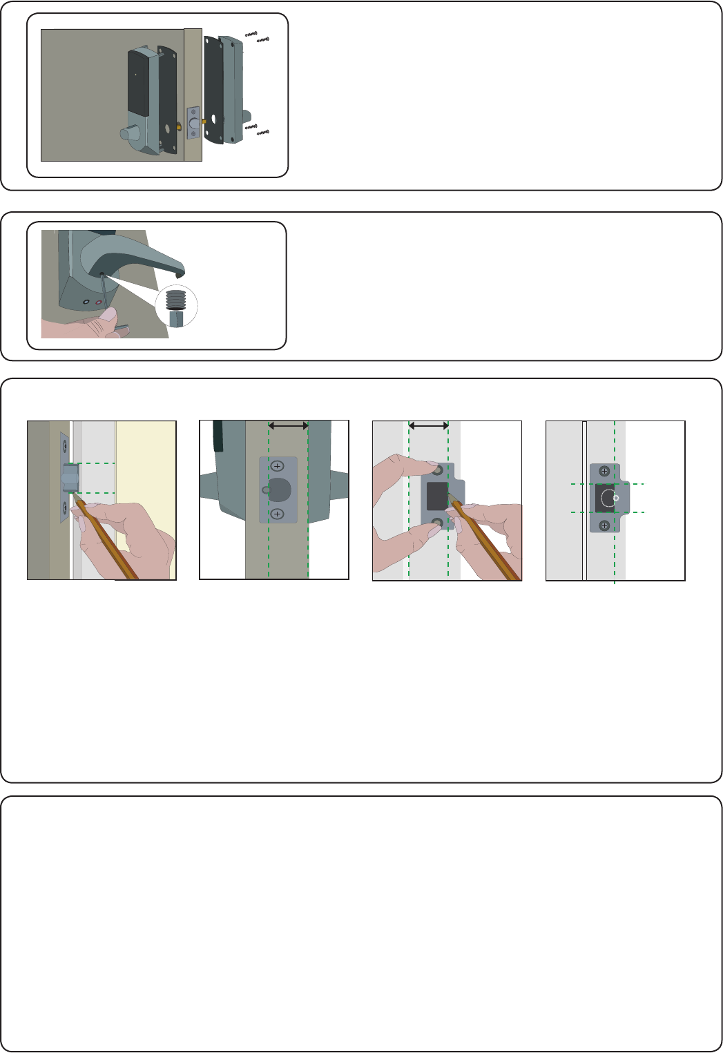
Fig A Fig B Fig C Fig D
Step 5 - Mounting on the door
Step 6 - Fitting the handles
Step 7 - Marking out the strike plate
Step 8 - Fitting the strike plate
Select the short (doors thinner than 1 3/4”) or long mounting
screws and cut to length if required.
(door thickness + 3/16”)
Fit the rubber escutcheons to the front and back plates.
Present the front and rear lock assembly to the door, locating
the square drive in its recess and join the two parts together
with 4 mounting screws.
Fit the two handles, positioning the screw holes to the
underside and secure with the grub screws provided.
Check the operation of the lock - See Commissioning checks.
Fig A - Vertical position of the strike plate - Close the door and mark the top and bottom position of the
latch horizontally across the frame.
Fig B - Horizontal position of the strike plate - Measure the distance from the back edge of the door to
the at face of the latch. (NOT the plunger.)
Fig C - Mark this distance on the frame to show how far back the plate needs to be to hold the door closed.
Fig D - Position the strike plate within these guide lines. Mark the positions of the xing screws and draw
around the ‘cut-out’ in the strike plate.
Chisel out a 5/8” aperture to receive the latch bolt.
Fix the strike plate with one latch screw to the surface of the frame.
FROM THE INSIDE: Gently close the door and check that the latch enters the aperture easily with no
additional ‘play’ in the frame. Slight adjustment can be made by moving the plate slightly. When satised,
draw around the outline of the strike plate, remove it. Score around the outline and then cut the rebate to
enable the strike plate to lie ush with the surface.
Fix the strike plate using two latch screws and check the lock operation. Remove the strike plate and
increase the aperture to accept the strike plate backbox. Now re-x the strike plate and check the operation
of the ‘anti-shim’ plunger and the door.
The unit is now fully operational and should be enrolled as soon as possible to preserve battery life.

Page 4
The current specication for compatible PC hardware, network and operating systems is available on our website
at the following link: http://paxton.info/720
There is NO Net2 Easyprox nano detection function. It is recognised that there could be security issues
if the wireless units were detectable from outside the site. During installation, a Nano unit makes a permanent
link with a Net2Air bridge which will then only talk to registered units. The Server conguration utility also has
an ‘ Enable commissioning’ mode which can be turned off to inhibit Nano units being added.
An entry is then made on the Doors screen and a special icon is used to denote the wireless connection.
With the product xed securely to the door:
1) Extend the door open time by changing this door’s settings on the Net2 PC. Set ‘ Door open time’ to 20
seconds and then present a user card at the door. Before each check, present a user card to unlock the door.
2) Check that the handles are running smoothly, this is best done by depressing the handle all the way to the
bottom and then releasing it as slowly as possible, if the handle is left behind at any point it is likely that the
product has not been installed squarely enough. Check the handle on both sides of the door.
3) If your nger is able to leave the handle, remove the Easyprox from the door (or slacken the four xing
screws) and see if the problem goes away. If it does, then the installation onto the door is at fault and the drilling
of the mounting holes should be checked for alignment.
4) Once the install has successfully passed this test return the door to normal operation by changing the PC
setting for this door back to its previous door open time (default 3 seconds) and present a user card.
This test conrms the correct and free operation of the mechanical lock and also ensures that the electronic
circuits will shut down correctly preserving battery life.
Commissioning checks
An Easyprox nano must rst bind to a Net2Air bridge before it will enroll itself onto the Net2 system. The term
‘bind’ is used to denote the xed relationship between a Nano and its bridge.
1. Create a user record in the database and assign a Net2 token to the user. This record can be deleted after
the installation is complete.
2. You must now wake up the Easyprox nano. This can be achieved by either raising your hand to be detected
by the PIR or moving the handle.
3. Present the same user token to the Easyprox nano which will then transmit the token number and wait for a
response from a bridge.
The software has the ‘Enable commissioning mode’ set as a default. If this has been turned off in the Server
conguration utility, it must be enabled for this process to succeed.
If more than one bridge replies, the Easyprox nano checks the signal strength and selects the strongest bridge
to communicate with. The Net2 software conrms that the token number is in the database and if so registers
this Nano/bridge as a permanent binding.
Enrolling an Easyprox nano
The Net2 software should be loaded on the controlling PC and at least one Net2Air bridge congured to
communicate with the Net2 nano unit.
Full documentation is supplied with the Net2Air bridge unit and also from the website as follows:
XAN1051 - Installing Net2 software < http://paxton.info/1520 >
XIns-30084-US Net2Air USB bridge < http://paxton.info/1453 >
XIns-30085-US Net2Air Ethernet bridge < http://paxton.info/1192 >
Software installation
The Blue LED will now ash for several minutes while its software is updated to match the current Net2 version.
Page 5
Wireless Net2Air activity is signalled by a Blue LED. This will ash each time the Easyprox nano
communicates with the Net2 software.
Presenting a valid user card to the unit will cause the LED to ash Green briey and the handle will then
engage. The unit will beep during this time to advise the user that access has been permitted.
The external handle is only engaged once access has been granted. The inside handle is always engaged.
Normal Operation - LED Indications
A button on the inside allows the internal handle to be held in the unlocked position.
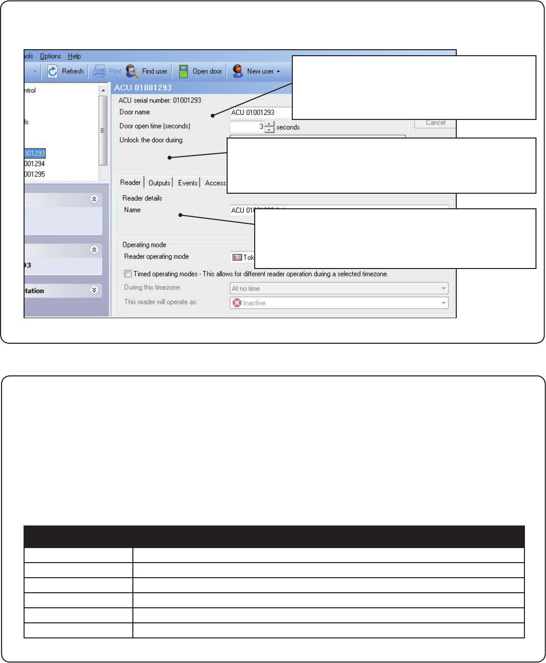
Software conguration
Name: Each reader can be named individually if required.
Reader operating mode: Set the operating mode.
Timed operating modes: A different operating mode can
be congured within a time window.
Reader: Local settings for the reader.
Output: Congures the lock for timed release or toggle mode.
Events: Shows the events for this control unit only.
Access Rights: Lists users who have access through this door.
Door name: Name the ACU.
Door open time: Set the door open time.
Unlock the Door during: Permanently unlocks
the door while this time zone is active. - Should
be set to ‘At No Time’ for normal user operation.
Blue
Green ash + beep
Red ash + low beep
Red ash 3 times
Amber constant ashing
Red constant ashing
Indicates wireless communication with the Net2 software
A valid user card has been presented and the handle is engaged
An invalid user card has been presented - No access granted
Activity has been sensed but no user card has been presented
A valid user card has been presented - the handle is not horizontal and so the latch cannot release
The handle is being held down - The latch cannot relock
LED indications

Page 6
Easyprox nano reset
The Easyprox nano holds the address information for the bridge that it has bound with. It will therefore never
communicate with any other bridge. This can cause problems if the unit is to be used in another location.
The unit requires a hardware reset to clear its bridge information. This is achieved as follows:
1. Remove the unit from the door by removing the 4 mounting screws on the rear lock assembly.
2. Remove the access plate at the rear of the front lock assembly (top two standoff screws).
3. Locate the reset push button at the lower right corner of the circuit board.
4. Hold the button down and wake up the unit by briey depressing the handle. The unit will give a single beep.
5. Push the reset button 4 more times and the unit will beep 5 times and display an AMBER LED.
6. Replace the access plate.
7. Enrol the unit - as above.
8. Ret the lock to the door with the 4 mounting screws.
The access control unit connects to the Net2 software running on the PC using Paxton Access’ Net2Air proprietary
wireless technology. A Net2Air bridge enables communication from the Net2 software to the Paxton Access nano
family of products.
Radio signals do not always behave as you might expect. For example, a mobile phone that displays a full signal
on one part of the site will lose signal completely only a few feet away. These problems can be addressed by using
the Net2 site surveyor kit. (690-200-US)
See also: XAN1095 - Net2 nano - How does it work? < http://paxton.info/974 >
X AN1096 - How to plan a Net2 nano installation < http://paxton.info/975 >
X Ins-30096-US - Net2Air site surveyor < http://paxton.info/1193 >
The Easyprox nano is a standalone unit and stays in a sleep mode while there is no activity. The Net2 server
cannot wake up the unit. If the PIR is activated or the handle moved, it powers up the reader circuits in readiness
for a token read. Should nothing occur within 3 seconds, the unit will go back to sleep.
If a token is read, then the Easyprox nano moves into full operation. The token number is checked against the
stored database and access is granted or denied as per a standard Net2 control unit.
The Easyprox nano now sends this data via its Net2Air bridge connection to the Net2 server software and the
blue LED will ash to indicate this activity. If any updates need to be sent to the unit, including changes to the
user data, these are now transmitted back. The unit will then go back to sleep again waiting for further activity.
After 1 hour of inactivity, the unit will send a heartbeat to the Net2 PC which responds with any updates, as
above. This keeps the Easyprox nano units updated even when there is no activity at the door. The 1 hour delay
is mitigated by the vastly increased battery life in each unit and the fact that any user activity (card read or
handle use) will also cause an immediate update to be made. It therefore follows that a new user may need to
trigger an update before being given access through a door.
Easyprox nano / server operation
Net2Air wireless communication
Radio frequency
The unit is set to channel 11 (2.405 GHz) as this frequency is normally clear of other device transmissions.
Technical Support can advise if you are concerned about interference from adjacent radio based (WiFi) equipment.
Some of the Net2 features (e.g. Fire alarm integration, Anti-passback) are not available on Nano products as
wireless communication is not suitable for data critical applications.
During the 1 hour sleep period, any changes at the PC will not be received. If an immediate card
update is required, the unit must be woken up by means of a user card or by briey depressing the
handle to initiate a data transfer.
To preserve battery life, a door held unlocked by a timezone will ignore the wakeup function. It will
check for updates, reducing in frequency from 1 minute to 1 hour while the door remains unlocked.
Page 7
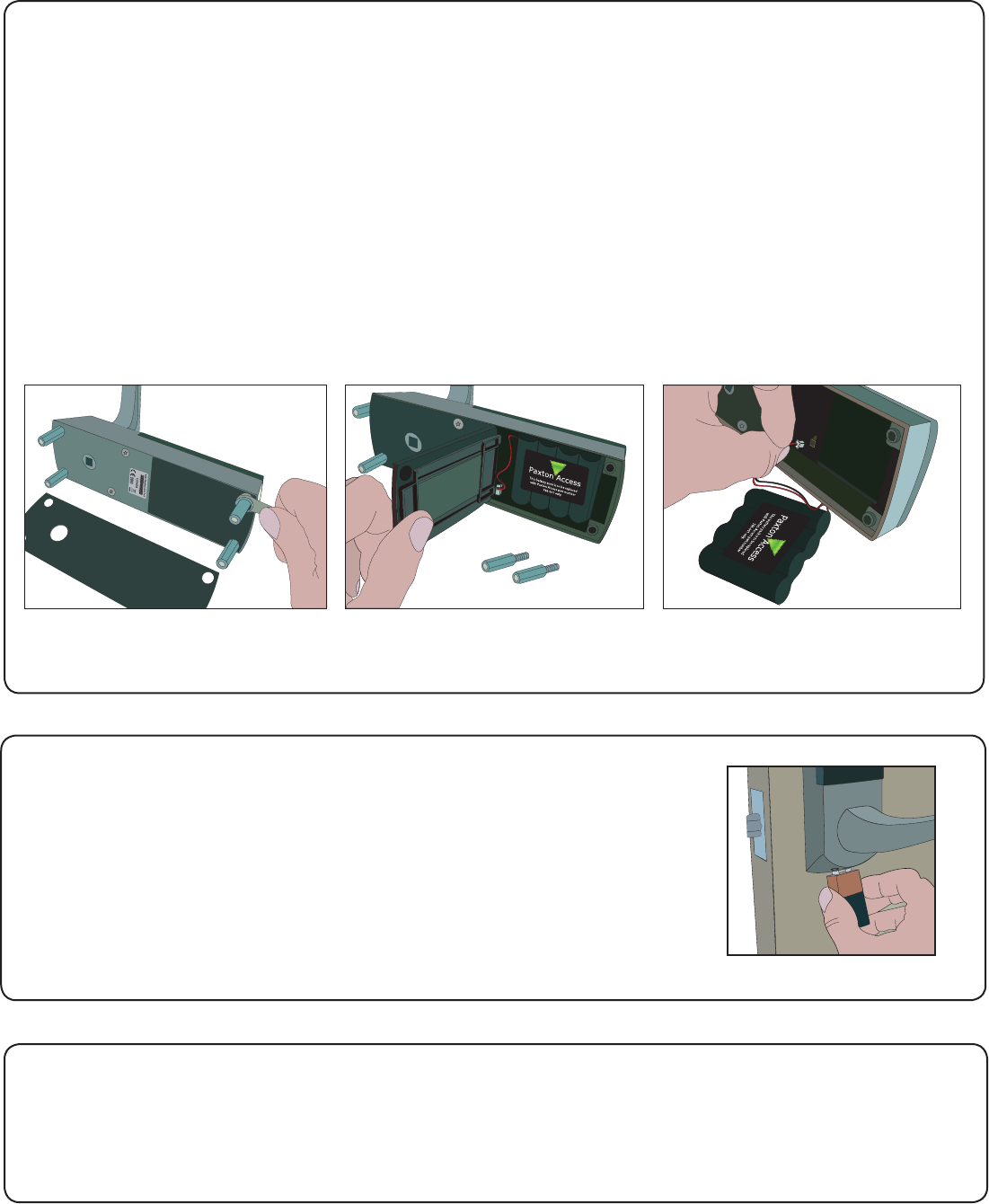
Battery replacement
1. Remove the unit from the door by removing the 4 securing screws on the rear lock assembly.
2. Remove the top two standoff screws - Fig 1.
3. Remove the access plate to reveal the battery pack. - Fig 2.
4. Unplug the lead and replace the pack with a new Paxton Access battery pack. - Fig 3.
(The unit will retain its settings and should not be manually reset).
5. Ret the access plate and secure.
6. Ret the unit to the door.
Fig 1 Fig 2 Fig 3
Recovery from a at battery
Should the battery pack become discharged, the unit will no longer function -
this could be in the locked or unlocked state. The application of an external PP3
9V battery will allow the circuitry to operate as normal.
This allows the door to be opened with a valid user card giving access to the lock
allowing the battery pack to be replaced.
+ve-ve
When the battery voltage falls below 4V, the user will see a delay between the card being read and access being
granted. This delay provides a warning that the battery pack should be replaced.
The warning delay starts at 5 seconds, increasing up to 25 seconds as the battery discharges with use.
Low battery warning
Alarm sounder
The alarm is activated when the door fails to re-lock itself. The alarm will sound for 60 seconds during which time
the unit will try to lock the door once every 10 seconds. After 60 seconds the unit will then shut down. When
the unit is woken up, it will immediately try to lock the door. If it fails, the alarm cycle will start again. Failure to
relock will substantially reduce battery life.

Page 8
10,000
250
64
1 sec 99,999 sec
10
100
20 yds
4,096
2 inch 1 inch
0 °C (-32 °F) +55 °C (+131 °F)
2 3/8 inch 7 5/8 inch 1 inch
6 inch 7 5/8 inch 2 7/8 inch
Operating temperature - Battery limits
Environment
Dimensions
Features
Waterproof
Min
Width Height
Max
Depth
Min Max
Access Levels
Time Zones
Maximum door open time
ACU’s per Net2Air bridge - Recommended
Events stored in ACU with no server connection
Number of Cards
Specications
No
Net2Air bridge (data lines) per system
Net2Air wireless range to ACU
30,000 operations up to 3 years
Paxton Battery Pack
Low
Reader/Keypad module (Required space on Door)
Total outside dimensions (includes handle clearence)
Battery type - High capacity (746-003)
Typical Battery Life
Vandal resistance
Read Range Keyfob
Token
This product is not suitable for retail sale. All warranties are invalid if this product is not installed by a competent person.
Use site surveyor
FCC Compliance
This device complies with Part 15 of the FCC Rules. Operation is subject to the following two conditions:
(1) this device may not cause harmful interference, and (2) this device must accept any interference
received, including interference that may cause undesired operation. Changes or modications not expressly
approved by the party responsible for compliance could void the user’s authority to operate the equipment.