Paxton Access 746583 Easyprox Compact Keypad User Manual INSTRUCTION Easyprox compact keypad
Paxton Access Ltd Easyprox Compact Keypad INSTRUCTION Easyprox compact keypad
Users Manual
11/12/2008
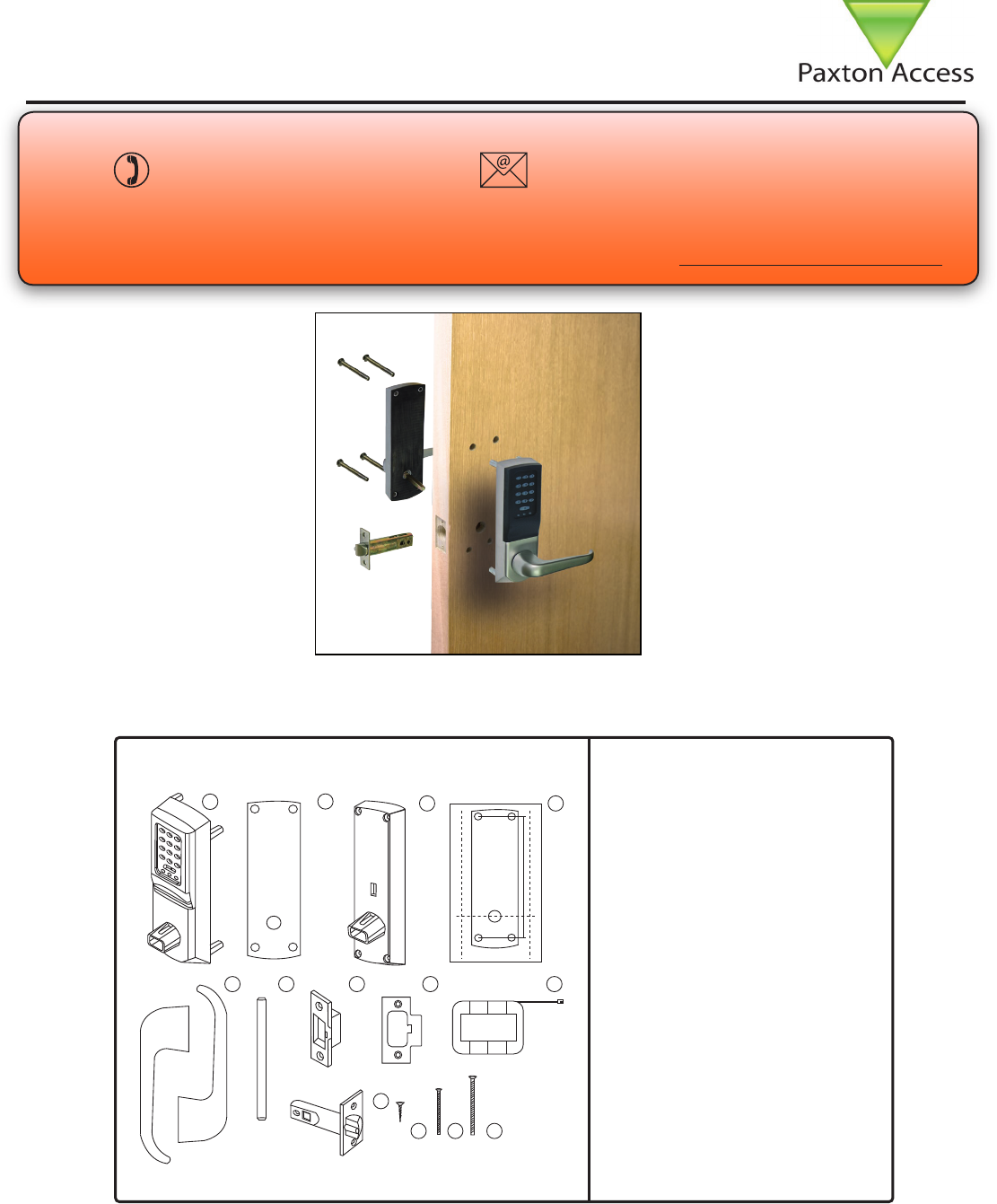
Layout
Parts list
Tools List
Power Drill
Drill bits 10mm, 25mm.
Philips screwdriver
Hacksaw for cutting bolts
Hammer / Mallet
Chisel 25mm
Stanley knife
Adhesive tape
Pencil
Tape measure
8mm spanner (supplied)
2mm Allen key (supplied)
1) Front Lock Assembly
2) Rubber Escutcheon x2
3) Rear Lock Assembly
4) Ins-30067 - Easyprox Template
5) Left and Right Handles
6) Square Drive
7) Strike Plate Backbox
8) Strike Plate
9) Battery Pack
10) Tubular Mortice Latch
11) Latch Screws x4
12) Short Fixing Screws x4
13) Long Fixing Screws x4
This unit is for Indoor use only.
Technical Support
Technical help is available: Monday - Friday from 5am - 5pm PST / 8am - 8pm EST
1 800 672 PAXT support@paxton.co.uk
Ins-30100-US Easyprox compact keypad
Documentation on all Paxton Access products can be found on our web site - http://www.paxton-access.com/
NOTE: All dimensions are shown in millimetres to maintain accuracy.
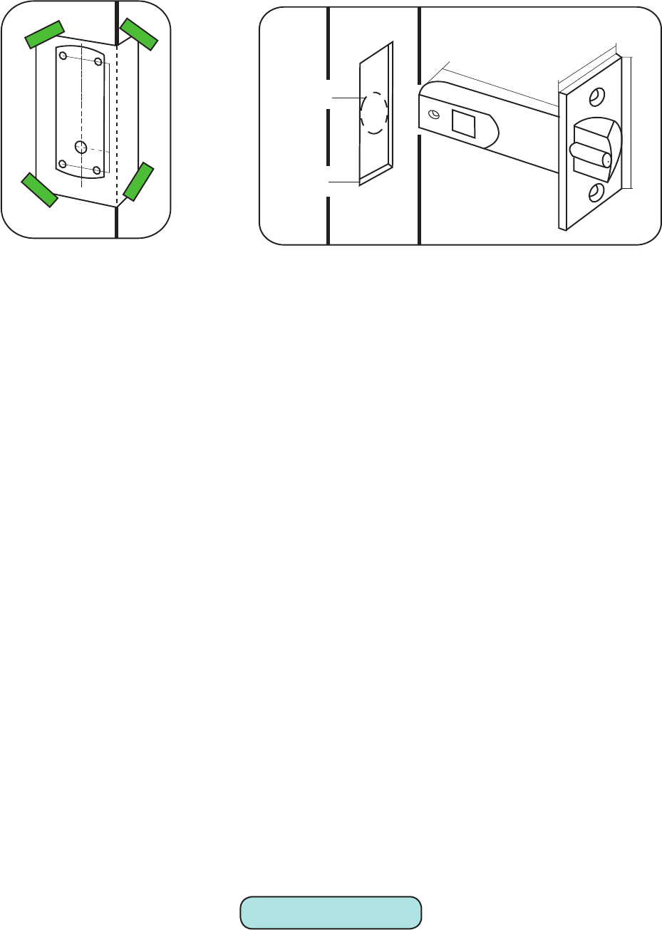
Fitting the latch
Step 1
Decide on the height of the latch and mark a line on the edge of the door and about 80mm across both faces. Fold
the template along one of the dotted lines (right or left). Tape it to the door, the latch centre line positioned on the
height mark. (Diagram A).
Mark the 4 x 10mm holes and 1 x 25mm holes. Remove the template and apply it to the other side of the door,
again aligning it with the height line. Mark the holes as before.
Step 2
Drill the 25mm hole on the centre line of the door edge at least 80mm deep to accept the latch.
Step 3
Drill the 4 x 10 mm holes for the xings and one 25mm hole for the square drive. To ensure accuracy you should
drill these holes from both sides of the door towards the centre. This also avoids the risk of damaging the door face
when the drill breaks through.
Step 4
Put the latch into the hole and draw around the edge of the faceplate. Remove the latch and score the outline with
a Stanley knife to avoid splitting the wood when chiselling. Chisel a 3.5mm rebate allowing a ush t for the latch.
(See diagram B).
Step 5
Re-t the latch with the plunger facing away from the door frame and secure with two latch screws.
NOTE. This plunger protects against the manipulation or ‘shimming’ of the latch with a credit card, etc.
Step 6
Cut the square drive to length ( Door thickness +20mm) and slide into the latch.
Step 7
Accurately measure the thickness of the door. (20mm minimum - 60mm max) For doors between 40mm to 45mm
and 55mm to 60mm thick the supplied securing screws (long or short) can be used without adjustment.
For doors outside of this range the long screws should be cut to length of approximately Door thickness + 5 mm.
Diagram A - Drilling template taped to door
25mm
57mm
80mm
3.5mm
25mm
Power up and Initialise
Diagram B - Latch dimensions
Step 8
With reference to ‘Battery Replacement’ remove the access plate at the rear of the unit by removing the top
standoff screws. (Fig 1) Take the battery pack and connect the lead to the white plug. (Fig 3) - The unit will
click twice and then commence to beep regularly.
Step 9
The unit must now be enrolled. Please refer to ‘Initialising a new System’.
The unit will stop beeping and is now active.
15mm
2.5mm
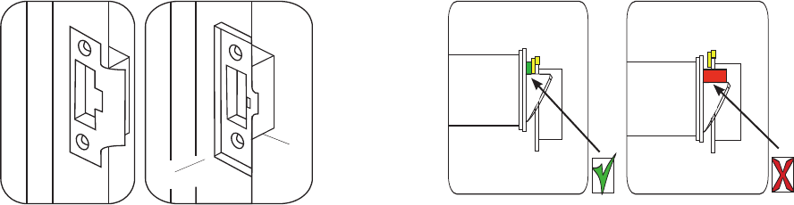
Diagram C - Strike plate and backbox Diagram D - Strike plate position - Anti-shim plunger
Fitting the strike plate and backbox
Step 10
Fit the battery pack into the unit. Replace the access plate and secure with the standoff screws.
Step 11
Fit the rubber escutcheons to front plate and the back plate. Present the front and rear lock assembly to the door,
locating the square drive in its recess and secure the two parts of the lock together with the xing screws. Fit the
two handles positioning the screw holes to the underside and secure with the grub screws provided.
Step 12
Check the operation of the lock by using the inside lever to check that the latch moves freely. If required, loosen
the xing screws and adjust the position of the lock assemblies until the lever handle and latch are all moving
freely. Tighten the xing screws.
Step 13
To determine the vertical position of the plate - Close the door against the frame and mark the top and bottom of
the latch where it touches the frame. - Transfer these lines horizontally across the frame rebate.
Step 14
To determine the horizontal position of the plate - Measure the distance from the back edge of the door to the at
face of the latch. (NOT the plunger.) Mark this distance on the frame to show how far back the plate needs to be
to hold the door closed.
Step 15
Position the strike plate so that the ‘cut-out’ lines up with the lines made in Steps 13 and 14. Mark the positions
of the xing screws and draw around the ‘cut-out’ in the strike plate. Chisel out a 15mm aperture to receive the
latch bolt. (Diagram C)
Step 16
Fix the strike plate with one latch screw to the surface of the frame.
FROM THE INSIDE: Gently close the door and check that the latch enters the aperture easily with no additional
‘play’ in the frame.
Slight adjustment can be made by moving the plate slightly. When satised, draw around the outline of the strike
plate, remove it. Score around the outline and then cut the rebate to enable the strike plate to lie ush with the
surface.
Step 17
Fix the strike plate using two latch screws and check the lock operation. Remove the strike plate and increase the
aperture to accept the strike plate back box. Now re-x the strike plate and check the operation of the ‘anti-shim’
plunger and the door. (Diagram D)
Step 18
The unit is now fully operational - See following pages for programming instructions and LED indications.
FCC Compliance
This device complies with Part 15 of the FCC Rules. Operation is subject to the following two conditions:
(1) this device may not cause harmful interference, and (2) this device must accept any interference received,
including interference that may cause undesired operation. Changes or modications not expressly approved by
the party responsible for compliance could void the user’s authority to operate the equipment.
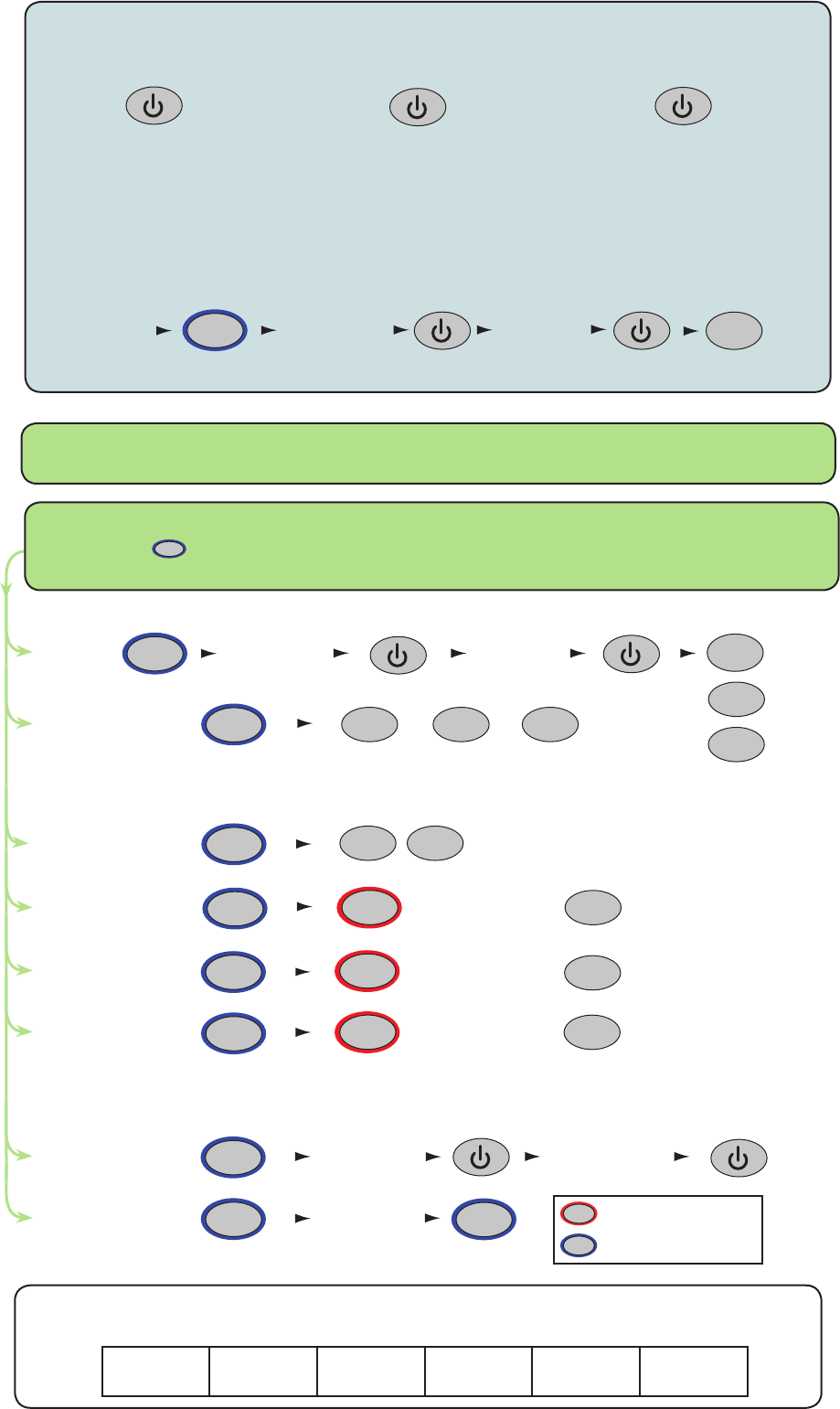
This box can be used to write down the Programming Code for future reference.
Ensure that this information is stored in a secure place.
Choose a 6 digit Programming Code and load this into the unit as follows:
IMPORTANT NOTE: Do not set the Programming Code to 123456
The programming code must not contain the same string of digits as the user code.
The default user code is 1234 - therefore the programming code must not be set to 123456
6 digit Programming
Code
The factory User Code is now set to 1234
6 digit Programming
Code
You can now set up the user codes and features using the programming chart.
Example: - Setting a user code to unlock the door under Normal condition
Enter user code
4-8 digits
Re-enter
user code 4
8
Enter 6 digit
Programming
Code
Hold for 3 secs Normal
X
Single or multiple
codes
Silent operation
20 wrong keystrokes
= 60 second lockout
Door open time
(seconds)
Change
Programming Code
Set a
user code
Data Reset (except
Programming code)
OR
One code only Multiple codes allowed
Silent
Beep on
OFF ON
Enter time in seconds
(default = 05, max = 60)
Enter user code
4-8 digits
Re-enter
user code
Enter 6 digit
Programming
Code
= Delete
= Normal
= Toggle
Enter 6 digit
Programming
Code
Re-enter 6 digit
Programming
Code
6
OR
OR
X
2
4
6
OR
OR
2
2
2
2
3
4
5
6
9
8
6
6
9
START - Enter the 6 digit Programming Code and hold down a function key
----- for 3 seconds. - The unit beeps and the LED ashes faster.
Continue the key sequence to set the option - The keypad returns to operating mode.
= default setting
= Hold down for 3 secs
1
Card
plus
PIN
Card
or
Code
Card
plus
code
23
OR OR
1
Combined Card &
Keypad modes
INITIALISING A NEW SYSTEM
TOUCHLOCK MODE
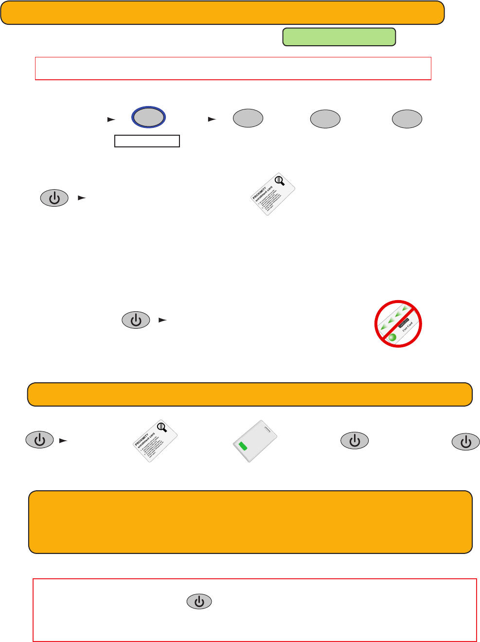
All tokens will now be validated.
Tokens can now be issued to users
Present the enrolment card
To bar a user:
The user card is now barred
Present/swipe user’s shadow card
Adding an additional Proximity card pack. You need to be in possession of a valid enrolment
card for this system. Present this enrolment card to the reader and the Amber LED will ash
with the Green & Red LEDs off. Present the Enrolment card from the new card pack. The reader
will beep and all LEDS will be lit. The additional cards will now be valid. Repeat this with each
reader and with any additional card packs. Any valid enrolment card can be used to add further
packs. If an incorrect enrolment card is used to start the process, the Red LED will be lit and the
reader will produce a squeak sound as it rejects the card.
PROXIMITY with TOUCHLOCK mode
(i) The unit must rst be initialised in TOUCHLOCK mode: See TOUCHLOCK section
IMPORTANT NOTE: Do not set the Programming Code to 123456
(ii) Before enrolling a card pack, set up the required operating mode, as follows:
(iii) Now present enrolment card
Card plus PIN. A card requires a 4 digit PIN to be assigned to it before it will work, as follows:
Present
enrolment card
Present
user card Enter PIN Re-Enter PIN
Card plus Code. User gains access by presenting a valid token and then entering a valid code.
Card or Code. User gains access by presenting a valid token or entering a valid code.
See Touchlock programming - Option 8 to set codes. (4 digits) - Option 2 to enable multiple codes.
1
Card plus PIN Card or CodeCard plus code
23
OR OR
Enter 6 digit
Programming
Code
Hold for 3 secs
1
Flashing Amber LED Flashing Yellow/Green LED Flashing Yellow/Green (faster) LED
IMPORTANT: Before presenting a PROXIMITY card to the reader, you must rst press
the POWER - - key or briey depress the handle.
The reader is then active for 2 seconds and will ash all the LEDS during this period.
This is to ensure maximum battery life.
A user can be re-validated by showing the enrolment card followed by the user
card or re-entered if used in Card+PIN mode.
Issuing tokens
1. Across each double page there are ‘pairs’ of cards - a ‘User card’ and a corresponding ‘Shadow card’.
2. Write the name of the user on the shadow card.
3. Issue the matching user card to the user.
4. Keep the card pack containing the shadow cards in a safe place.
1
2
3
4
Bar a user
1. When a card is lost or stolen it is important to bar the card from your system to avoid unauthorized access.
2. To bar a card or token take it’s corresponding shadow card from the card pack.
3. Swipe the shadow card through the reader. This will remove the lost card or token from your system.
4. A barred card can re-validated by swiping the enrolment card followed by the user card through the reader.
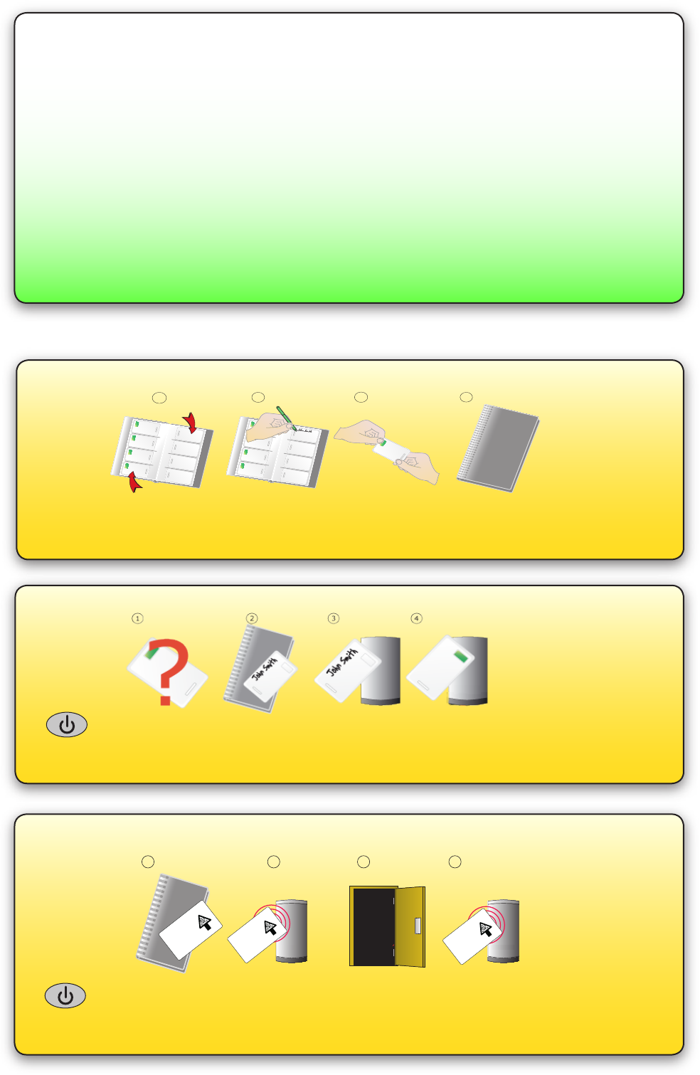
Door held open
A button on the inside allows the internal handle to be held in the unlocked position.
NOTE: The Fail Open release card has the same function as a door held open card.
1. Take the fail open release function card from the starter pack
2. Present the card to the reader. The reader will beep for about a second
3. The door is now set to be permanently open.
4. To relock the door, present the card again, the reader will bleep once.
1 2 3 4
BEEP!
BEEP!
Fail open release card
This card is used with
systems where a fail open
electric release is used for
safe operation in the event of
a fire. Swipe the card through
the reader to drive a fail open
release or maglock. Swipe
the card again to revert to fail
closed operation.
Fail open release card
This card is used with
systems where a fail open
electric release is used for
safe operation in the event of
a fire. Swipe the card through
the reader to drive a fail open
release or maglock. Swipe
the card again to revert to fail
closed operation.
Fail open release card
This card is used with
systems where a fail open
electric release is used for
safe operation in the event of
a fire. Swipe the card through
the reader to drive a fail open
release or maglock. Swipe
the card again to revert to fail
closed operation.
The external handle is free to move and is only engaged once access has been granted.
The inside handle is always engaged.
When access has been granted, the unit will ash the Green LED and the handle will
then engage. The unit will beep during this time to advise the user that access has been
permitted. This default time (4 seconds) can be changed with the ‘door open time’ card.
Presenting an invalid or barred card will ash the Red LED and sound a low tone. Access is
denied.
ALARMS - The handle must be horizontal to operate the latch. If it is not horizontal when a
valid card is presented, the LED will ash Amber until the handle is again horizontal when
the latch will then release.
Normal Operation - LED Indications
Enrolment Card - must be presented when the system is
rst powered on
1. Take the enrolment card from the new pack of user cards
2. Present the enrolment card to the reader
3. The reader will beep as the enrolment card is acknowledged
4. All cards in the pack are now valid. The enrolment card can now be returned to it’s pack.
Door open time
1. Take the door open time function card from the starter pack.
2. Present the card to the reader. The reader will start beeping.
3. Wait for the required period you wish the door to remain open.
4. Present the card again at the end of the period to set the open time. The beeping will stop.
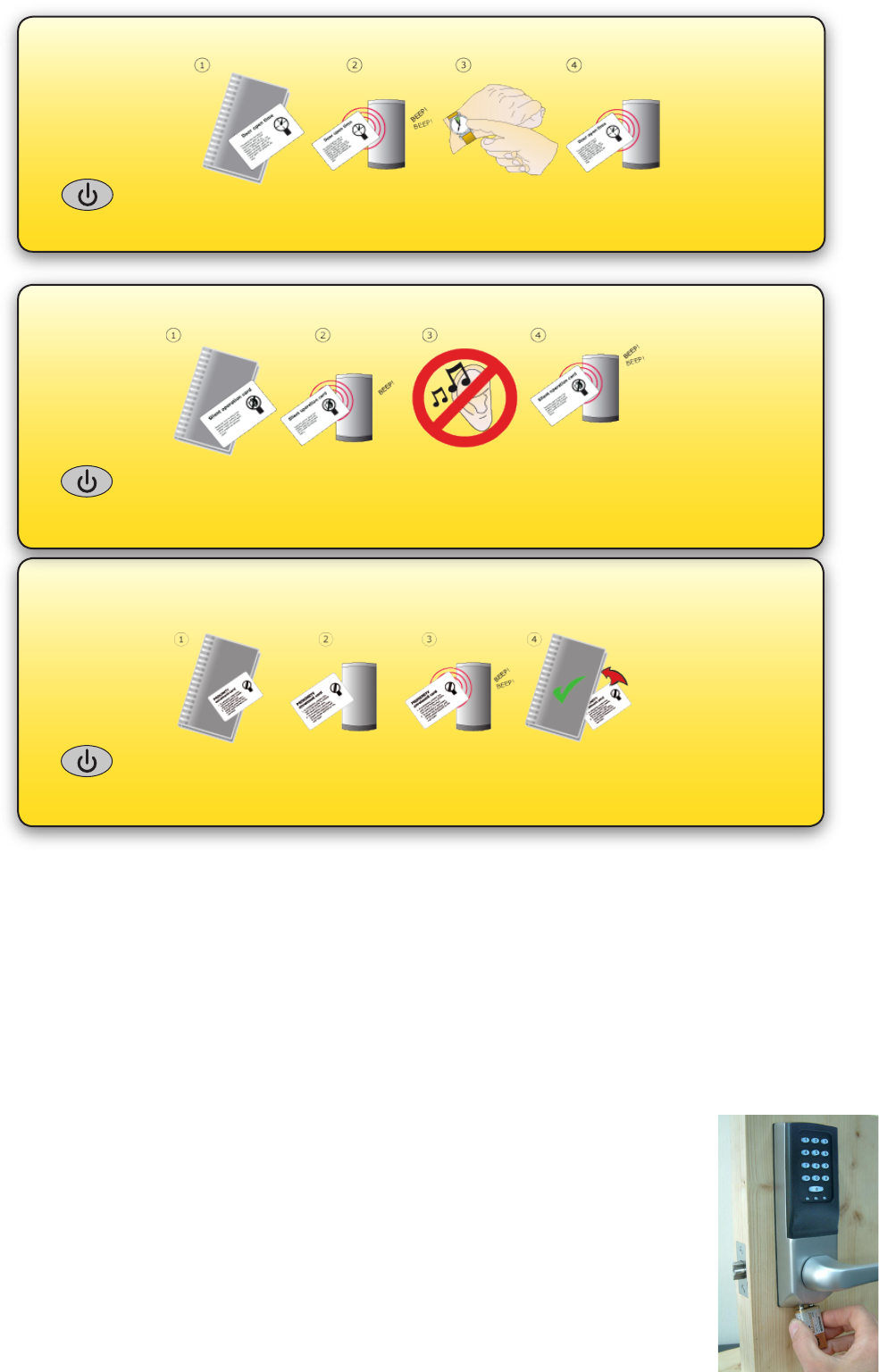
When the battery has discharged to within the 3.5-4V minimum operating threshold, the user will experience a
delay between the card being read and access being granted. This delay acts as a warning that the battery pack is
low and should be replaced.
As an example; the initial delay will be 5 seconds. The user will present their card as normal and the green LED
will ash slowly for the 5 second delay, after which access is granted normally.
The delay will increase in increments up to 25 seconds as the battery continues to discharge.
Low battery warning
Silent operation card
1. Take the silent operation function card from the starter pack
2. Present the card to the reader. The reader will beep
3. The reader is now in silent operation mode
4. Present the card again to disable silent operation mode. The reader will beep twice.
Recovery from a at battery
Should the battery pack become discharged, the unit will no longer function and the
door mechanism will then fail to operate - this could be in the locked or unlocked state.
There is provision on the underside of the lock to apply an external PP3 9V battery that
will provide voltage to allow the circuitry to operate as normal. The +ve terminal is the
Right of the pair.
NOTE: This does not release the lock directly but allows the door to be opened with a
valid user card. Once the door is open, access to the lock will allow the internal battery
pack to be replaced. +ve-ve
The system will also accept colour zone function cards
110,000
1100
1 sec 60 sec
1 3
0 °C (32 °F) 55 °C (131 °F)
50 mm 30 mm 10 mm
60 mm 194 mm 30 mm
150 mm 194 mm 72 mm
Specications
Min Max
Min Max
Environment
Dimensions
Features
Waterproof
Width Height Depth
Door open time
Number of Packs
Silent operation
Number of Users
Access levels (Colour Zones)
Operating temperature - Battery limits
Yes
No
Battery Type
Typical Battery Life 30,000 operations up to 5 years
Paxton Battery Pack
Full System Reset
1. Remove the unit from the door by removing the 4 securing screws on the rear lock assembly.
(see layout on rst page)
2. Remove the access plate at the rear of the front lock assembly. (top two standoff screws).
3. Locate the reset button at the lower right corner of the circuit board.
4. While holding down the reset button, press the Power button once on the main keypad.
- The unit will beep 2 times.
5. Immediately, press and release the reset button 4 more times - The unit will beep to conrm each press
- the unit will then produce a series of 5 rapid beeps and display a ashing GREEN LED.
6. Remove and replace the battery plug. - Press the Power button and the unit will start to beep and
display ashing GREEN AND RED LEDs - RE-ENROLL and test the unit.
7. Replace the access plate.
8. Ret the lock to the door with the 4 xing screws.
< OR >
1. Present Enrolment card.
2. Present Door open time card twice.
3. Present Enrolment card.
4. Present Door open time card twice.
5. WAIT FOR 5 SECONDS!
This function should only be used to clear all the stored user
information from the unit. The unit is returned to its Factory
settings and will require initialising again (See: Enrolment Card)
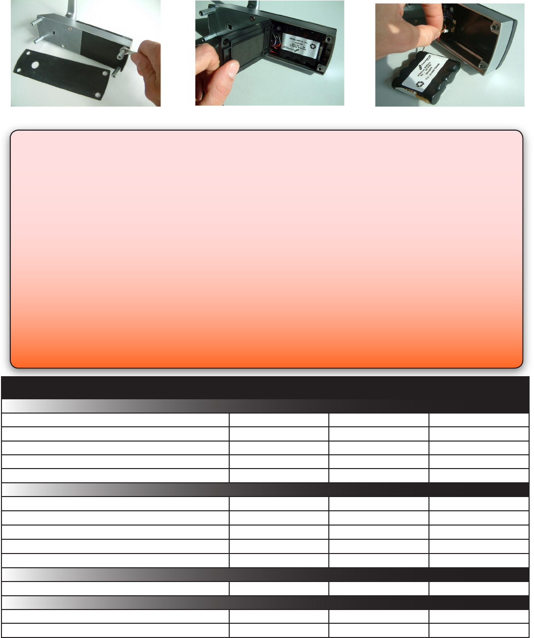
Battery replacement
1. Remove the unit from the door by removing the 4 securing screws on the rear lock assembly.
(see Layout on front page)
2. Remove the top two standoff screws - Fig 1
3. Remove the access plate to reveal the battery pack. - Fig 2
4. Unplug the lead and replace the pack with a new Paxton Access battery pack. - Fig 3.
(NOTE: The unit will retain its settings and should not be manually reset)
5. Ret the access plate and secure.
6. Ret the unit to the door
Fig 1 Fig 2 Fig 3
Read Range Keyfob
Token Watchprox
Vandal resistance Low
Reader/Keypad module (Required space on Door)
Total outside dimensions (includes handle clearence)