Paxton Access WR01 Wireless Reader Module User Manual INSTRUCTION Wireless reader module
Paxton Access Ltd Wireless Reader Module INSTRUCTION Wireless reader module
User Manual
19/12/2008
Cable extensions
Readers can be extended using Belden CR9540 10-core overall screened cable. The maximum length is 100 yards.
Technical Support
Technical help is available: Monday - Friday from 5am - 5pm PST / 8am - 8pm EST
1 800 672 PAXT support@paxton-access.co.uk
Ins-30095-US Wireless reader modules
Documentation on all Paxton Access products can be found on our web site - http://www.paxton-access.com/
The Net2Air wireless reader modules consist of two parts. The ACU module and the Remote module. The ACU
module is plugged into the reader port of the control unit. The Remote module is located at the distant location
and contains a reader port and a lock relay that replicates the switching of the ACU’s own relay.
A 12V DC power supply is required for the remote module. This may also be used for lock power.
This module repeats the basic input and output functions of the ACU.
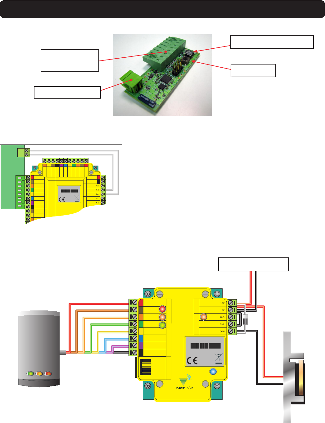
The unit has a reader port (8 way plug and RJ45), power input and relay connection. Mount the unit and then
wire in the remote equipment (reader, lock, etc). A suitable 12V DC power supply is also required.
LED indications
Red Red reader LED
Amber Amber reader LED
Green Green reader LED
Amber Relay activated (COM / NO contacts closed)
Blue Net2Air network activity (Transmit or Receive)
Green PCB Power
This module plugs directly into the reader port on the ACU. If the relay position is also to be repeated by the
remote module a VOLT FREE loop connection should be made between the relay condition input and the COM
and NO contacts on the controller relay. (See Wiring section)
ACU module
LED indications
Blue Net2Air network activity (Transmit or Receive)
Amber Mode - The system is unlocked to allow a remote module to be registered.
Green A token has been presented at the remote module.
Remote Module
Operation
NOTE: The module provides the power for this detection circuit. No voltage or diode should be connected at the
ACU control relay or either PCB may be damaged.
The typical range in an ofce environment is 5 yards. Where there is clear ‘line of sight’ across an open space,
(warehouse roof void, car park, etc) a range of 30 yards is possible. (See Wireless limitations)
12V dc
Red LED
Amber LED
Reader Reader RJ45
PowerRelay
Green LED
Data
Clock
Media Detect
Network
0V
Wireless reader module
PLACE SERIAL
NUMBER
LABEL HERE
HTTPPAXTONINFO
0889
Wiring
ACU Module
Remote Module
Reader port plug
connection
Screen or spare cores from
network cable
K
R1
r
e
da
e
d
a
p
y
e1
R le ay 2 R le ay 1
Keypad 2 Reader 2
stupnI P ewo r
Net2 classic
Red 12V dc
Red LED
Amber LED
Green LED
Data/D0
Clock/D1
Media Detect
0V out
Load
Data
Clock
Rc
d
V
2
1
d
e
RDE
L
d
e
DE
L
r
e
b
m
A
DE
L
n
e
e
r
G
0
D
/
a
t
a
D
1
D
/
k
c
o
l
C
t
c
e
t
e
D
a
i
d
e
M
t
u
o
V
0
d
a
o
L
a
t
a
D
k
c
o
l
C
+12V
0V
F
:
no
i
t
u
aC r
o y
l
no
s
r
e
da
e
r
c.
d
V
2
1.F
t
c
e
r
ro
c
r
o
n
o
i
t
c
e
n
n
o
c fo f
e
r
s
r
e
d
a
e
r
V
5
d
lo r
eo
t
s
no
i
t
c
u
r
t
s
n
i
PLACE SERIAL
NUMBER
LABEL HERE
HTTPPAXTONINFO<
0889
Wire the relay condition input across the COM / NO of the relay
to be monitored. This will vary with ACU style.
NANO - Do NOT use the powered Lock connection on this ACU.
The module monitors volt free relay connections.
The lock is wired across 12V and COM. A 0V link is then required to complete the circuit. This will be wired from 0v
to NO or NC depending on lock type (Fail Open / Fail Closed)
A diode is supplied which should be tted across 12V and COM (Silver end to 12V ) to protect the relay contacts.
Reader
Fail closed release
12V DC power supply
Relay condition input
Radio Frequency Selector
Mode Button

Power up the remote unit and the 3 LED’s on the reader (repeated next to the reader port on the module) will
cycle showing that no ACU module is currently paired with this unit. The Blue network LED will ash indicating
that the module is looking for an ACU module to pair with.
Plug in the ACU module and power up the controller. the Blue LED will start to ash, indicating that it is searching
for remote modules.
Press the button on the ACU module to turn on the Mode LED (Amber). This unlocks the system to register any
remote module that is not already paired. When this is successful, the remote module reader LED’s will stop
cycling and display a steady indication.
To secure the system, the button on the ACU module should be pressed once again to turn off the Mode LED. This
will also happen automatically after 10 minutes.
Installation
Multiple unit installation
One ACU module is able to register up to 7 remote modules. Each module should be powered up in turn and will
be registered automatically by the ACU module, providing that you have set the Mode LED to be on.
DO NOT alter the rotary switch setting unless there is radio interference. (See later notes). This switch is used to
alter the radio frequency used by Net2Air and is NOT a unit selection switch.
Loss of signal
Loss of power
Wireless limitations
The system uses a 5 second heartbeat to conrm that the two modules are still paired successfully. If this check
fails, the reader LEDS will cycle while it tries to re-establish the link. If this is a regular occurrence, the modules
may need to be re-sited to rectify this situation.
If there is a power failure at either module, they will automatically re-establish communication once the power has
been restored. The relay in the remote module will RELOCK while there is no communication taking place.
All wireless communication will be inuenced by the ‘Multi path’ effect. In essence it is one radio signal being split
into several signals each time it is reected by an object. These signals arrive at slightly different times at the
receiver which then has difculty in determining the content of the original data.
Floors, ceilings, desks, shelving etc will all contribute to these reections and so the following general rules should
be adopted to reduce this effect to a minimum.
- In an ofce environment, you should mount the modules mid way between the desk height and the ceiling. This
will minimise the reections from either surface. With higher ceilings, mounting a module one arms length above
head height is a good guide. This keeps the signal above human trafc and also avoids surface reections.
- Avoid corner or ‘dead end’ locations as the signal will be reected by the multiple surfaces.
- Where possible, mount module pairs on walls that are facing each other as this maximises the ‘line of sight’ that
can be achieved.
Fixed obstructions. These will be walls, racking, cabinets, etc. They are often made of metal or have a metal
reinforcement that will block the data signal.
Moveable obstructions. These include storage bins, vehicles, people, etc. You need to be aware of this if trafc
levels vary on a daily basis. Again we are trying to maintain a clear line of sight between the two radio modules.
Compatible with hands free tokens
Where hands free operation is also required, the hands free interface must be installed between the P series
reader and the wireless remote module. (for wiring, see instructions included with the hands free interface)
During installation, allow the hands free interface to upgrade the P series reader to hands free operation. Once this
has been done, any further LED indications will be as per this document.
Microwave ovens, bluetooth and wi- networks, halogen display lighting and other high enegy devices can all
interfere with wireless communication. Try to mount these modules away from such sources.
-20 °C (-4 °F) +55 °C (+131 °F)
30 yards
9V DC 14V DC
600 mA
500 mA
2.4 GHz
600 µs
4 3/4 inch 4 3/4 inch 1 1/2 inch
2 3/4 inch 1 1/2 inch 1/2 inch
Voltage
Clock and data bit period
Carrier frequency
Specifications
Operating temperature
Electrical
Environment
Dimensions
Min Max
Width Height Depth
Waterproof
Max
Min
No
This product is not suitable for retail sale. All warranties are invalid if
this product is not installed by a competent person.
Further information on how to purchase Installer Tools is available at: http://paxton.info/841
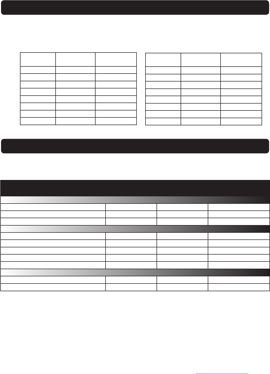
The radio frequency channel used for the Net2Air transmissions can be changed on the ACU module by means
of a rotary switch. This does NOT need to be changed where multiple units are in use on the same site. It
provides alternative channels where RF interference is suspected as causing difculties in maintaining a reliable
radio signal.
0 2.405 11
1 2.41 12
2 2.415 13
3 2.42 14
4 2.425 15
5 2.43 16
6 2.435 17
7 2.44 18
GHz
Switch
position
IEEE 802.15.4
channel
Radio frequency
Either unit can be cleared of its network settings should it be needed in another location. Hold down the PCB
push button while powering up the unit.
Data Reset
8 2.445 19
9 2.45 20
A 2.455 21
B 2.46 22
C 2.465 23
D 2.47 24
E 2.475 25
GHz
Switch
position
IEEE 802.15.4
channel
Distance between modules
Current - Remote Module
Current - ACU Module
Remote Module in Housing
ACU Module
FCC Compliance
This device complies with Part 15 of the FCC Rules. Operation is subject to the following two conditions: (1) this
device may not cause harmful interference, and (2) this device must accept any interference received, including
interference that may cause undesired operation. Changes or modications not expressly approved by the party
responsible for compliance could void the user’s authority to operate the equipment.